PJM Generation Interconnection Request Queue #A55 Lakewood 230kV Facilities Study Report
|
|
|
- Isabella Hamilton
- 6 years ago
- Views:
Transcription
1 PJM Generation Interconnection Request Queue #A55 Lakewood 230kV Facilities Study Report September 2001
2 Table of Contents DESCRIPTION PAGE 1.0 Introduction Description of Facilities Included in Study Facility Study Results Whitpain 230kV CB Replacements Project Overview 10 Appendix A (Project Milestone Schedule/Overall Schedule) 13 Appendix B (Alternative Arrangements) 19 Appendix C (Existing and Proposed 1 Line) 22 Appendix D (Lakewood Technical Work Scope) 26 Appendix E (Interconnection Installation) 32 2
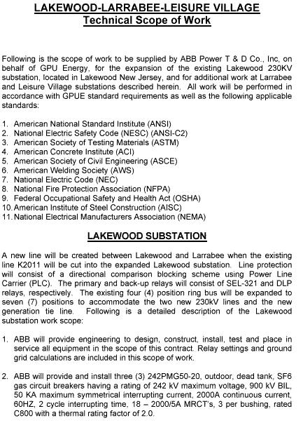
3 1. Introduction 1.1. Project Description This project involves modifying GPU Energy s existing 230 kv Lakewood CoGen substation. This substation is located at 123 Energy Way in Lakewood, New Jersey. The substation is adjacent to the 236 MW dispatchable Lakewood CoGen combined cycle power plant. The substation expansion is required to facilitate the export and transmission of an additional 500 MW of plant generation to be constructed at the site. The existing substation presently ties Con Ed Development s 236 MW generation power capacities to the GPU transmission system. Con Ed Development is planning to install an additional 500MW of generation capacity adjacent to the existing power plant facility. The new generating facility consists of three simple cycle GE 7FA combustion turbine generators. The initial combustion turbine is scheduled for operation in August A facility impact study identified the need to expand the existing substation to accommodate two additional 230kV lines into the existing GPU substation. The substation modification will provide enhanced power paths and increased reliability for exporting and transmitting the additional power. The existing four-breaker ring bus requires expansion to a seven-breaker ring configuration in order to accommodate a new 500 MW generation connection and (2) transmission line connections. Splitting the existing 230 kv K2011 line will create the two new transmission line terminal connections at the Lakewood CoGen substation. The K2011 line presently interconnects the GPU Larrabee station and the GPU Leisure Village station traversing the same corridor with the Z2026 line from Larrabee to Lakewood CoGen and the U2021 line from Leisure Village to Lakewood CoGen. The new line created from Lakewood CoGen to Larrabee will retain the designation K The new line created from Lakewood CoGen to Leisure Village will be designated D In addition to the work required at Lakewood three 230kV circuit breakers at Larrabee substation need to be replaced because their short circuit interrupting capability will be exceeded by installation of the Lakewood (Ocean Peaking Power) generation. The project will also be allocated cost for the replacement of two over-dutied 230kV circuit breakers at Whitpain substation as explained in section Project Milestone Schedule See appendix A. 3
4 1.3. Changes from the Impact Study Since the initiation of the Facilities Study projects A38, A42 and A43 have withdrawn from the Generation Interconnection queue. This has resulted in a reduction in the network upgrades required for the Lakewood (Ocean Peaking Power) project. Specifically the replacement of a wave trap on the I1023 line at Raritan River and the need to replace the W1037E 230kV circuit breaker at Raritan River. Scope of GPU Energy Work 2. Description of Facilities Included in Study 2.1. Rearrangement of Existing 230 kv Transmission Line (K2011) The K2011 line will be cut and the two ends (Larrabee and Leisure Village) will be terminated in the expanded portion of the substation ring bus Substation Expansion The existing 230 kv, four-breaker ring bus will be expanded to accept the two new lines created by cutting and intercepting the K2011 line. The station expansion will also accommodate a new 230 kv short transmission line from the new generating plant. The resulting substation expansion will be configured into a seven-breaker ring. The ring bus will be designed for a maximum current rating of 2,000 amperes and a short circuit rating of 50 kaic Protection Systems GPU is in the process of installing 230 kv breakers on the U2021 and D2030 lines at Leisure Village, and a directional comparison-blocking scheme utilizing Power Line Carrier (PLC) for relay communication between Leisure Village and Larrabee as well as between Lakewood and Leisure Village. The in service date is June 1, 2001 for this work. These modifications will create a Lakewood CoGen to Leisure Village circuit in place of the existing Lakewood CoGen to Manitou circuit. Once circuit K2011 is cut into the Lakewood CoGen substation, the section of line between Lakewood CoGen and Leisure Village will retain the frequencies being presently used on the existing Larrabee-Leisure Village circuit for the directional comparison blocking scheme. The new relays to be installed at the Lakewood CoGen station will match the relays GPU is in the process of installing at Leisure Village A new line will be created between Lakewood CoGen and Larrabee when the existing K2011 line is cut into the expanded Lakewood substation. This line will 4
5 be protected with a directional comparison-blocking scheme using PLC. A frequency of 92Khz has been chosen for this new line. The primary and back-up relays will consist of SEL-321 and DLP relays for primary and backup protection, respectively. Shortening of the line between Larrabee and the Lakewood CoGen site when K is cut into the new ring bus at Lakewood CoGen will necessitate relay replacement of the existing electromechanical line relays used for the K-2011 line protection at the Larrabee substation. The new line protection scheme will consist of SEL-321 and DLP relays for primary and backup protection, respectively. The following CT ratio changes will be required at Larrabee, in conjunction with the replacement of 230kV breakers BG. GK and K4 : a) Breakers "GK" and "BG" CTs associated with G-1021 Line Relays, presently used as bus differential relays: Connect the current transformers on the new circuit breakers 1200/5 to match the ratios used on the capacitor 3 and 4 circuit breakers. b) Breakers "K4" and "GK" CTs associated with K-2011 Line Relays: Since a 2000/5 CT ratio will be required for the "K4" breaker to handle the 796 MVA load capability specified by the GPUE Transmission Planning group, CTs on both the "K4" and "GK" breaker will be connected to a 2000/5 ratio for the K-2011 line relays. c) 230kV breakers "K4" and "4R" and 34.5kV breakers "4A" and "4B" CTs associated with Bank 4 differential HU relays: To meet load requirements, the CTs on the 230 kv "K4" and "4R" circuit breakers will be connected using a 2000/5 CT ratio. Since these CTs are used in the differential scheme for Bank 4, a set of auxiliary CTs with a ratio of 10/5 which are already installed on the 34.5 kv side of the differential circuit but presently not in use will be connected to the HU/T4 differential relays. The CT ratios on the 34.5 kv BK4A and BK4B circuit breakers will be changed to 1500/5 that will effectively change the overall ratio associated with the differential inputs from the 34.5 kv BK4A and BK4B circuit breakers to 3000/5. The relay settings will be revised as required. d) Breakers "RZ", "4R", and Bank 8 CTs associated with R-1032 Line Relays: To meet load requirements, the CT ratios on the CTs on the 230 kv "RZ" and "4R" circuit breakers used for the R-1032 line relays must be changed from 1200/5 to 2000/5. This change will also require that a set of auxiliary CTs with a 1.66/1 ratio be installed on the Bank 8 CTs used for 5
6 the R-1032 line protection to match the 2000/5 ratio for the line relays. The relay settings will be revised as required. e) Breakers "RZ", "ZD", and Bank 3 CTs associated with Z-2026 Line Relays: To meet load requirements, the CT ratios on the CTs on the 230 kv "RZ" and "ZD" circuit breakers used for the Z-2026 line relays must be changed from 1200/5 to 2000/5. This change will also require that a set of auxiliary CTs with a 1.66/1 ratio be installed on the Bank 3 CTs used for the Z-2026 line protection to match the 2000/5 ratio used for the line relays. The relay settings will be revised as required. 3. Facility Study Results kV Circuit Rearrangement - The K2011 line, running in the transmission corridor adjacent to the existing substation, will be cut and brought into the station to enhance the capacity and reliability of power export from the station. The line rearrangement is needed as part the transmission infrastructure improvements to accommodate the planned increased capacity of the power plant. - The K2011 line is an existing transmission line that connects the GPU Larrabee station to the GPU Leisure Village station. This line shares the same structures and therefore traverses the same corridor as the Lakewood CoGen to Leisure Village Line (U2021) and the Lakewood CoGen to Larrabee Line (Z2026). - Existing circuit Z-2026 presently terminates at a position protected by breakers ZA and ZB, while circuit U-2021 is terminated between breakers UA and UB. - The existing K2011 line will be cut in the vicinity of the Lakewood CoGen Plant and two line terminals created. In order to avoid crossing any 230kV lines, circuit Z-2026 will be relocated to a new bus position (see proposed alternate B one line in Appendix C). The position vacated by circuit Z-2026 between breakers ZA and ZB will be used for the new Lakewood-Leisure Village line (D-2030). - Two options were proposed for connection to the station (see Appendix B). Option B was selected to prevent the loss of two Larrabee lines in case of a stuck breaker operation during a line fault. - The length of the Leisure Village to Lakewood CoGen Line is approximately 4 miles. The length of the Larrabee to Lakewood CoGen line is approximately 12 miles. - There are no environmental impacts or considerations relative to the line work proposed. Existing Rights-of-Way and transmission corridors will be utilized. 6
7 - The existing line and the taps to the station expansion are rated 230 kv, AC, and consists of double circuit overhead tower and pole line construction. - The new taps to the station will be accomplished via inter-built tapered tubular poles that match existing construction. Tension spans will be utilized from the tap poles to A-Frame or H-Frame dead end towers inside the station area. - The line and shield conductor size will match existing construction wherever practical and feasible Lakewood 230 kv CoGen Substation Modifications - The purpose of the expansion is to provide the necessary capacity and reliability for the proposed 500 MW power plant expansion. - The existing substation is configured as a four-breaker ring bus. There are two position dedicated to two line terminals, Z 2026 and U2021. There are two positions dedicated to the existing power plant generation power path connections. The ring will be expanded to a seven-breaker ring bus configuration. This configuration will accommodate the two new line terminals created by breaking the K2011 line with the installation of two positions in the ring. The third position created on the ring will be dedicated to the power path connection from the new power plant. - Consultations with the Town of Lakewood Building Department revealed that a construction permit is the only permit required by the Town. - Discussion with the Town of Lakewood Zoning Department indicate the Town may waive the formal zoning review since the substation expansion was indicated in the original zoning board plan submission. - Electrical design will be based on a nominal voltage of 230 kv and a nominal current rating of 2,000 amperes. Rigid bus and strain bus will be used in the design for the station expansion. The short circuit interrupting rating will be designed for 50 kaic. Present worst-case short circuit levels are on the order of 32 kaic for three phase bolted faults and 36 kaic for single line to ground faults. Gas circuit breakers will be used for the three additional circuit breakers. Refer to Appendix D for a full description of the technical work scope. - The civil and structural design will be based on existing design parameters. Existing structure types and material will be used as is appropriate. New foundation design will model existing conditions, as is feasible. Soil boring logs have been reviewed and indicate a soil bearing pressure of 3,000 lbs. would be suitable for design. The size and type of the foundations will match existing conditions as is feasible. - The fence, gates and access roads will be modified to accommodate the larger substation. 7
8 - A topographic survey, including existing benchmarks has been completed. - A new control building extension/expansion will be constructed adjacent to the existing control building. The building will include the new relay protection, SCADA and communications as well as a new DC power plant Leisure Village Substation Modifications - There is no requirement for any system upgrades at Leisure Village directly attributable to the Lakewood generation addition. The extent of the required work is related to line relay testing during testing and commissioning of circuits U-2021 and D-2030 protection schematics Larrabee Substation Modifications - The protection of the new Lakewood-Larrabee line will consist of a directional comparison-blocking scheme via PLC. The only requirements at Larrabee will be to re-tune the carrier frequency to 92Khz, and the replacement of the carrier set with one having the same 92Khz frequency. Breakers K4, GK and BG will be replaced to address increased short circuit duty resulting from the additional generation at Lakewood. These SF6 gas breakers will be nominally rated 230kV, 3000A. Scope of PECO Work 4.0. Whitpain 230V CB Replacements 4.1 Purpose and Necessity The Impact Study analysis for project A55, as well as all other Queue A projects, used a short circuit analysis methodology that screened for potential overdutied circuit breakers at locations where a project had a contribution equal to or greater than 3% of the circuit breaker s rating. This 3% threshold was used to determine when a project had a cost allocation responsibility for an overdutied circuit breaker. When Queue A Impact Studies were being performed, it was recognized that a particular circuit breaker s rating could be exceeded by the aggregate impact of a number of projects where no single project was found to contribute a short circuit current increase equal to 3% or more of that circuit breaker s rating. The term creepers was used to designate the small group of overdutied circuit breakers which would not be identified in any Queue A impact study but would ultimately be determined when a comprehensive short circuit analysis was performed for the Regional Transmission Expansion Plan. The possible existence of creepers, and allocation of cost assignment to Queue A projects for upgrade of creepers, was communicated publicly at TEAC meetings for Queue A projects. 8
9 Results from the recently completed comprehensive short circuit analysis for the Queue A Regional Transmission Plan determined that creeper overdutied circuit breakers were found to exist. Those that are of concern to the Lakewood (A55) project are at Whitpain 230kV substation for which analysis determined that Project A55 has cost allocation responsibility. According to the most current information, the cost allocation (based on relative short circuit current contribution of short circuit contribution to the affected circuit breakers after 100% of rating is exceeded) is as follows: Whitpain CB #115 Cost ($250,000 est.) 13.9% - Project A30 $ 34, % - Project A36 $ 17, % - Project A55 $ 20, % - Project A59 $177,050 Whitpain CB #225 Cost ($250,000 est.) 3.0% - Project A29 $ 7, % - Project A30 $ 37, % - Project A55 $ 21, % - Project A59 $182, Material List A detailed material list can be provided upon request upon completion of final design. 4.3 Cost Estimate The total cost estimate for the A55 Lakewood Project share of the breaker replacement is $20, 843 plus $21,604 for a total of $42,447. This is direct material cost. 4.4 Engineering Design Schedule, and Equipment Procurement and Construction Schedule Not established at this point in time. PJM is currently developing a procedure for the timing requirements associated with the replacement of creeper overdutied circuit breakers. The issues which will be addressed by the procedure include; (1) Providing certainty for full Capacity Interconnection Rights (CIRs) to the Interconnection Customer, and (2) Minimizing the possibility that a circuit breaker is replaced too far in advance of actual need or when not required. 9
10 Based on the information available at this time, the interconnection of project A55 will result in the need for circuit breaker replacements at Whitpain 230kV substation. The cost allocation for project A55 may vary from the percent listed above to potentially 100% if other projects withdraw their Generator Interconnection Request. Other projects in Queues B and C may also be assigned some cost responsibility to reduce the cost allocation to project A55. Therefore, Project A55 must provide security for its allocated cost. Additional security may be required in the future if the cost allocation to the Lakewood Project increases. 5.0 Project Overview 5.1. Total Cost of Facilities & Allocated Cost to Project Developer 10
11 GPU ENERGY OCEAN PEAKING POWER INTERCONNECTION ESTIMATED COSTS (FERC BREAKOUT, GPU FACILITIES) ATTACHMENT FACILITIES Direct Indirect Carrying Total Cost Cost Cost Cost Labor $ 567,091 $ - See $ 567,091 Materials $ 527,909 $ - Note $ 527,909 Total ABB & GPUE $ 1,095,000 $ - Below $ 1,095,000 $ 1,095,000 LOCAL UPGRADES Direct Indirect Carrying Total Cost Cost Cost Cost Labor $ - $ - See $ - Materials $ - $ - Note $ - Total ABB & GPUE $ - $ - Below $ - $ - NETWORK UPGRADES Direct Indirect Carrying Total Cost Cost Cost Cost Labor $ 1,590,627 $ 30,999 See $ 1,621,626 Materials $ 1,596,359 $ 8,611 Note $ 1,604,970 Total ABB & GPUE $ 3,186,986 $ 39,610 Below $ 3,226,596 $ 3,226,596 ALL FACILITIES Direct Indirect Carrying Total Cost Cost Cost Cost Labor $ 2,157,719 $ 30,999 See $ 2,188,718 Materials $ 2,124,267 $ 8,611 Note $ 2,132,878 Total ABB & GPUE $ 4,281,986 $ 39,610 Below $ 4,321,596 $ 4,321,596 $ 4,321,596 Note: Developer shall reimburse Jersey Central Power & Light Company d/b/a GPU Energy for depreciation, taxes, return, and ongoing operations and maintenance expenses by way of a series of payments over twenty-five years. The basis for these charges is the FERC Fixed Charge Worksheet for Jersey Central Power & Light Company, as filed with the FERC under Docket ER The actual payments shall be based upon GPU Energy's actual investment in this project, which is likely to differ from the estimates shown in this exhibit. GPU Energy shall impose no Carrying Cost upon the Developer, other than the Return component provided under the FERC Fixed Charge Worksheet described above. 11
12 The Costs for the breaker replacement at Whitpain 230kV substation is $42,447, all of which are direct equipment costs Summary of Construction Schedules & Overall Construction Schedule for Facilities See Appendix A Comparison of Facilities Construction Schedule with Project Developers Milestone schedule Con Ed Development required ready for service date is April 30, Although it would have been preferable to complete the 230 kv bus expansion work by November 30, 2001, this will not be possible due the time involved with the permit requirements. 5.4 Interconnection Customers Milestone Schedule Initial energization April 2002 Unit #1 commercial operation August 2002 Unit #2 commercial operation October 2002 Unit #3 commercial operation To be determined 12
13 APPENDIX A PROJECT MILESTONE SCHEDULES 13
14 Lakewood 14
15 Lakewood 15
16 INTERCONNECTION INSTALLATION SCHEDULE OF WORK (Limited to Lakewood Substation) This Schedule of Work is limited to GPU Energy Attachment Facilities, GPU Energy Local Upgrades and GPU Energy Network Upgrades at Lakewood Substation. It excludes GPU Energy Additional Facilities that may be required to be installed at the Larrabee substation and the Raritan River substation. Task Name Estimated Days Required to Complete Task (See Note 1) Site Mobilization 11 Civil Construction 38 Install Conduit & Cable Trench 49 Grounding Installation 90 Install New Building Addition 92 Structural Steel Erection 104 Control Cable Installation 124 Bus & Switch Installation 178 Receive & Install Breakers 136 Replace DC Battery & Charger 136 Control & Protection Installation 181 Install RTU 195 Testing & Commissioning 249 Project Completion Deadline 250 Note 1: Estimated Days are measured from date when GPU Energy receives all local and state building permits necessary to commence construction. 16
17 Larrabee Replace Circuit Breakers K4 and GK at Larrabee. (Duration: 16 days. Start: Mon 05/25/02. Finish: 06/15/02) 1. With the newly formed transmission pathways established between Larrabee and Leisure Village feeding through the expanded ring bus at the Lakewood Cogen facility, the existing K2011 line will be taken out of service by opening breakers K4 and GK at Larrabee, and breaker K at Leisure Village. 2. ABB will mobilize crews at Larrabee for the breaker replacement phase of the project. Breakers K4, GK and BG will be replaced as part of the overall project scope. 3. Breakers K4 and GK at Larrabee will be isolated by their respective disconnect switches. These breakers will be disconnected and removed from service. The new 3000A circuit breakers will be installed on existing foundations. All breaker leads and connectors will be replaced. Junction boxes will be installed at each breaker location in order to utilize existing breaker control cables. 4. ABB will replace the existing K2011 line relays at Larabee with SEL-321 (Primary) and GE- DLP (Backup) protection according to GPU Energy standards. ABB will also replace the existing carrier set, and retune the line tuners during this step. 5. Breaker BG at Larrabee will remain in service until breakers K4 and GK are replaced, fully tested and returned to service, so as to avoid an outage on the G1021 line to Atlantic Substation. It is anticipated that it will take approximately 3 weeks to replace these two circuit breakers,install the new line relays, test and recommission the system. Replace Circuit Breaker BG at Larrabee. (Duration: 10 days. Start: Mon 06/15/02. Finish: 06/26/02) 1. At Larrabee Substation, ABB will replace breaker BG with another new 3000 A circuit breaker, along with the breaker leads and connectors. This will cause an outage on the capacitor banks, and a brief outage of the B1042 line, by opening breaker HB. All relaying will remain unchanged for the G1021 line. ABB will provide settings for all relays, and commission the new breaker BG as well as perform functional testing. Once functional testing is complete, breaker BG may be placed back in service. It is anticipated that it will take approximately 2 weeks to replace this circuit breaker. 17
18 Change CT Ratios of RZ and 4R at Larrabee. (Duration: 2 days. Start: 06/29/02. Finish: 07/01/02) 1. ABB will request that 230 kv Breakers RZ and 4R at Larrabee associated with Bank #8 and Bank #12 be opened. During this outage, to meet load requirements, the CT ratios of these breakers will be changed from 1200/5 to 2000/5. This change will also require a set of auxiliary CTs with a 1.66/1 ratio to be installed on the Bank #8 CTs used for R1032 line protection to match the 2000/5 ratio for the line relays. It is anticipated that this outage will take approximately 3 days. Change CT Ratios of Units K4 and 4R at Larrabee. (Duration: 4 days. Start: 07/02/02. Finish: 07/06/02) 1. Finally, ABB will request that 230 kv Breakers K4 and 4R at Larrabee associated with Bank #4 be opened. During this outage, ABB will change the CT ratios on both these breakers to 2000/5. Since these CTs are used in the differential scheme for Bank #4, a set of auxiliary CTs with a ratio of 10/5 which are already installed on the 34.5 kv side of the differential circuit but presently not in use will be connected to the HU/T4 differential relays. The CT ratios on the 34.5 kv breakers BK4A and BK4B will be changed to 1500/5, which will effectively change the overall ratio associated with the differential inputs from the 34.5 kv breakers BK4A and BK4B to 3000/5. 18
19 APPENDIX B ALTERNATIVE ARRANGEMENTS 19
20 20
21 21
22 APPENDIX C EXISTING AND PROPOSED ONE LINE DIAGRAMS 22
23 23
24 24
25 Larrabee 230kV Substation Breaker Replacement to Bank 9 to Atlantic to Bank 4 to Bank 3 to Bank 8 to Smithburg ZO RZ 4R HD K4 to Smithburg HB BG GK to Lakewood to Lakewood to Bank 7 to Cookstown 230 kv new 25
26 APPENDIX D LAKEWOOD TECHNICAL WORK SCOPE 26
27 27
28 28
29 29
30 30
31 31
32 APPENDIX E GPU ENERGY INTERCONNECTION INSTALLATION SCOPE AND SCHEDULE OF WORK 32
33 INTERCONNECTION INSTALLATION SCOPE OF WORK Services to be performed by GPU Energy: GPU Energy will provide all materials, equipment, tools, engineering, drafting, labor, supervision, project management, civil work, electrical construction, and testing needed to design, furnish and install the GPU Energy Interconnection. Additional items for interconnection and reinforcement may be identified, the interconnection configuration may change, and the actual costs may materially differ from the estimated costs shown below. In addition, Con Ed Development will pay for all actual costs incurred by the GPU Energy. Estimated Company Additional Item Project Description Facilities Cost 1 Company Attachment Facilities... $ 1,095,000 a. Provide and install an additional 230kV bus position to the existing four (4) ring bus at Lakewood Substation. 2 Company Local Upgrades... $ 0 a. No Company Local Upgrades have been identified. 3 Company Network Upgrades... $ 3,226,596 To alleviate 34.5kV circuit overloads $ 2,274,696 a. Provide and install two (2) additional bus positions to the existing 230kV 4 position ring bus at Lakewood Substation to accommodate two (2) new 230kV lines at Larrabee substation. b. Cut the existing Larrabee Leisure Village line K-2011 and route into expanded Lakewood 230kV ring bus. Relocate Larrabee Lakewood line Z-2026 from existing ring bus position to a new 230kV bus position to prevent the need to cross any lines. c. Upgrade the CT ratios at Larrabee substation on several breakers around the ring bus and install auxiliary CTs as required. Re-set and calibrate relays as required. d. Replace the existing electromechanical relays at Larrabee substation associated with the Lakewood line K Replace existing carrier set, re-tune the wave trap to a new frequency of 92kZ. 33
34 To alleviate circuit breaker short circuit duty problems at Larrabee $ 951,900 e. Replace existing 230kV, 2000A breakers BG, GK and K4 at Larrabee substation with 3000A breakers Total... $ 4,321,596 34
Elbert County 500 MW Generation Addition Interconnection Feasibility Study Report OASIS POSTING # GI
 Executive Summary Elbert County 500 MW Generation Addition Interconnection Feasibility Study Report OASIS POSTING # GI-2003-2 Xcel Energy Transmission Planning January 2004 This Interconnection Feasibility
Feasibility Study. Shaw Environmental, Inc. 12MW Landfill Gas Generation Interconnection. J.E.D. Solid Waste Management Facility. Holopaw Substation
 Feasibility Study Shaw Environmental, Inc. 12MW Landfill Gas Generation Interconnection J.E.D. Solid Waste Management Facility Holopaw Substation September 2013 1 of 12 Table of Contents GENERAL... 3 SHORT
Transmission and Distribution Substation Projects. Operating Company: Entergy Gulf States - Texas. Customer: PID # 202
 Transmission and Distribution Substation Projects Operating Company: Entergy Gulf States - Texas Customer: PID # 202 Funding Project Number: F4PPGS0386 Facility Study for PID # 202: Study for 146 MW Revision
Generation Interconnection Facilities Study For
 Generation Interconnection Facilities Study For Prepared for: Prepared by: SCE&G Transmission Planning May 27, 2015 TABLE OF CONTENTS General Discussion... Page 3 Generator Interconnection Specifications...
Interconnection Feasibility Study Report Request # GI Draft Report 600 MW Wind Generating Facility Missile Site 230 kv Substation, Colorado
 Executive Summary Interconnection Feasibility Study Report Request # GI-2016-6 Draft Report 600 MW Wind Generating Facility Missile Site 230 kv Substation, Colorado Public Service Company of Colorado Transmission
Memorandum. This memorandum requires Board action. EXECUTIVE SUMMARY
 California Independent System Operator Memorandum To: ISO Operations (MRTU) Committee From: Armando J. Perez, Director of Grid Planning cc: ISO Board of Governors ISO Officers Date: April 29, 2005 Re:
Interconnection Feasibility Study Report GIP-023-FEAS-R1. Generator Interconnection Request # MW Wind Generating Facility Inverness (L6549), NS
, NS") Interconnection Feasibility Study Report GIP-023-FEAS-R1 Generator Interconnection Request # 23 100 MW Wind Generating Facility Inverness (L6549), NS February 16, 2006 Control Centre Operations Nova Scotia
Interconnection Feasibility Study Report GIP-023-FEAS-R1 Generator Interconnection Request # 23 100 MW Wind Generating Facility Inverness (L6549), NS February 16, 2006 Control Centre Operations Nova Scotia
Interconnection Process for Generation Systems
 Interconnection Process for Generation Systems I. INTRODUCTION...1 II. GENERAL INFORMATION...2 A. Definitions...2 B. Nodak Electric Cooperative, Inc. Generation Interconnection Contacts...3 C. Engineering
Generation Interconnection Feasibility Study For XXXXXXXXXXXXXXXXXXXXXX MW generator at new Western Refinary Substation
 Generation Interconnection Feasibility Study For XXXXXXXXXXXXXXXXXXXXXX 131-250 MW generator at new Western Refinary Substation System Planning Section April, 2005 TABLE OF CONTENT 1 EXECUTIVE SUMMARY
Interconnection System Impact Study Report Request # GI
 Executive Summary Interconnection System Impact Study Report Request # GI-2008-23 34 MW Solar Generation Ranch at Hartsel, Colorado Public Service Company of Colorado Transmission Planning August 19, 2010
Generator Interconnection Facilities Study For SCE&G Two Combustion Turbine Generators at Hagood
 Generator Interconnection Facilities Study For SCE&G Two Combustion Turbine Generators at Hagood Prepared for: SCE&G Fossil/Hydro June 30, 2008 Prepared by: SCE&G Transmission Planning Table of Contents
High Lonesome Mesa 100 MW Wind Generation Project (OASIS #IA-PNM ) Interconnection Facility Study. Final Report November 2, 2007
 Interconnection Facility Study. Final Report November 2, 2007") High Lonesome Mesa 100 MW Wind Generation Project (OASIS #IA-PNM-2006-02) Interconnection Facility Study Final Report November 2, 2007 Prepared by: Public Service Company of New Mexico Electric Services
High Lonesome Mesa 100 MW Wind Generation Project (OASIS #IA-PNM-2006-02) Interconnection Facility Study Final Report November 2, 2007 Prepared by: Public Service Company of New Mexico Electric Services
Interconnection Feasibility Study Report GIP-226-FEAS-R3
 Interconnection Feasibility Study Report GIP-226-FEAS-R3 System Interconnection Request #226 70 MW Wind Generating Facility Kings County (L-6013) 2010 07 21 Control Centre Operations Nova Scotia Power
100 MW Wind Generation Project
 A subsidiary of Pinnacle West Capital Corporation 100 MW Wind Generation Project CUSTOMER FINAL Feasibility Study Results By Transmission Planning, APS December 21, 2007 Executive Summary This Feasibility
Reliability Analysis Update
 Reliability Analysis Update Transmission Expansion Advisory Committee October 11, 2018 Proposal Window Exclusion Definitions The following definitions explain the basis for excluding flowgates and/or projects
Wheeler Ridge Junction Substation Project Description and Functional Specifications for Competitive Solicitation
 Wheeler Ridge Junction Substation Project Description and Functional Specifications for Competitive Solicitation 1. Description In the 2013-2014 Transmission Planning Cycle, the ISO approved the construction
ISO Rules Part 500 Facilities Division 502 Technical Requirements Section Interconnected Electric System Protection Requirements
 Applicability 1 Section 502.3 applies to: the legal owner of a generating unit directly connected to the transmission system with a maximum authorized real power rating greater than 18 MW; the legal owner
BEFORE THE NEW JERSEY BOARD OF PUBLIC UTILITIES
 EXHIBIT JC-2 BEFORE THE NEW JERSEY BOARD OF PUBLIC UTILITIES IN THE MATTER OF THE PETITION OF JERSEY CENTRAL POWER & LIGHT COMPANY PURSUANT TO N.J.S.A. 40:55D-19 FOR A DETERMINATION THAT THE OCEANVIEW
TABLE OF CONTENTS FIGURES: MAP EXHIBITS: TABLES:
 TransWest Express Transmission Project TABLE OF CONTENTS 7.0 DESIGN OPTIONS... 7-1 7.1 OVERVIEW OF DESIGN OPTIONS... 7-1 7.2 DESIGN OPTIONS PURPOSE AND NEED AND DESIGN CHARACTERISTICS... 7-4 7.2.1 Design
FIRSTENERGY S PROPOSED SOLUTION AND REQUEST FOR CONSTRUCTION DESIGNATION
 PJM RTEP - Artificial Island Area FIRSTENERGY S PROPOSED SOLUTION AND REQUEST FOR CONSTRUCTION DESIGNATION Part 1 Report REDACTED VERSION FirstEnergy Corp. Energy Delivery, Transmission Planning and Protection
PJM Generator Interconnection R81 Emilie (Fords Mill) MW Impact Study Re-Study
 MW Impact Study Re-Study") PJM Generator Interconnection R81 Emilie (Fords Mill) 100.9 MW Impact Study Re-Study August 2008 DMS # 498781 General Queue R81 Emilie (Fords Mills) is a Fairless Energy, LLC request to obtain an additional
PJM Generator Interconnection R81 Emilie (Fords Mill) 100.9 MW Impact Study Re-Study August 2008 DMS # 498781 General Queue R81 Emilie (Fords Mills) is a Fairless Energy, LLC request to obtain an additional
PID 274 Feasibility Study Report 13.7 MW Distribution Inter-Connection Buras Substation
 PID 274 Feasibility Study Report 13.7 MW Distribution Inter-Connection Buras Substation Prepared by: Entergy Services, Inc. T & D Planning L-ENT-17A 639 Loyola Avenue New Orleans, LA 70113 Rev Issue Date
The Long-Range Transmission Plan
 The Long-Range Transmission Plan 2015 2025 Matt Koenig Presentation to ESPWG / TPAS October 29 th, 2015 Long-Range Transmission Plan Driver of the Plan is to maintain local reliability 10-year planning
The Energy Queensland Group Notice of no non-network options
 The Energy Queensland Group Notice of no non-network options 24 September 2018 MCE Mount Crosby East Establish new substation to replace Mount Crosby Substation (SSMTC) Page 1 of 1 DISCLAIMER While care
Q0044 interconnection at
 Generation Interconnection Feasibility Study Report for Q0044 interconnection at Utah County Utah on PacifiCorp s Transmission System (138 kv Transmission System) September 15, 2004 Page 1 1.0 Description
TEN YEAR PLANNING GUIDE SHASTA LAKE ELECTRIC UTILITY
 TEN YEAR PLANNING GUIDE SHASTA LAKE ELECTRIC UTILITY 2011-2020 P+ PowerPlus Engineering A Department of STAR Energy Services, LLC TEN YEAR PLANNING GUIDE 2011-2020 SHASTA LAKE ELECTRIC UTILITY CITY OF
Schedules 1 to 4, Lot B: Extension of the Lessos Substation
 1.0 LIGHTNING ARRESTORS 1.1 ZNO lightning arrester, 192 kv rated voltage, 10 ka nominal discharge current 2.0 CAPACITIVE VOLTAGE TRANSFORMER ea. 45 2.1 220 kv capacitive voltage transformer 220/ 3 / 0.11/
CUSTOMER/ TWIN ARROWS PROJECT
 A subsidiary of Pinnacle West Capital Corporation CUSTOMER/ TWIN ARROWS PROJECT V1 Facility Study Report APS Contract 52149 Prepared by: Arizona Public Service Company Transmission & Distribution Asset
GENERATOR INTERCONNECTION FACILITIES STUDY FOR DAN RIVER STEAM PLANT COMBINED CYCLE PROJECT With BIOMASS CONVERSION IN PLACE ROCKINGHAM COUNTY, NC
 GENERATOR INTERCONNECTION FACILITIES STUDY FOR DAN RIVER STEAM PLANT COMBINED CYCLE PROJECT With BIOMASS CONVERSION IN PLACE ROCKINGHAM COUNTY, NC Prepared by: Fred Kimsey Geno Price Roger Hurst Steve
Interconnection Feasibility Study Report GIP-157-FEAS-R2
 Interconnection Feasibility Study Report GIP-157-FEAS-R2 System Interconnection Request #157 100.5 MW Wind Generating Facility Guysborough County (L-6515) 2009 09 14 Control Centre Operations Nova Scotia
FINAL FACILITY STUDY. 230/69/13.8 kv Transformer Addition(s) at Badwater Substation 2009 T1. September 10, 2010
 at Badwater Substation 2009 T1. September 10, 2010") FINAL FACILITY STUDY 230/69/13.8 kv Transformer Addition(s) at Badwater Substation 2009 T1 September 10, 2010 I. Introduction This is a revised facility study performed for Transmission Queue Request 2009
FINAL FACILITY STUDY 230/69/13.8 kv Transformer Addition(s) at Badwater Substation 2009 T1 September 10, 2010 I. Introduction This is a revised facility study performed for Transmission Queue Request 2009
Sub-Regional RTEP Committee PJM South
 Sub-Regional RTEP Committee PJM South SRRTEP - South December 1, 2016 www.pjm.com PJM Baseline Project B2185 Update Problem: NERC Category B Violation (DVP Analysis) The 2017 summer base case indicates
Sub Regional RTEP Committee Western Region ATSI
 Sub Regional RTEP Committee Western Region ATSI February 20, 2019 1 ATSI Needs Stakeholders must submit any comments within 10 days of this meeting in order to provide time necessary to consider these
Interconnection Feasibility Study Report GIP-222-FEAS-R3
 Interconnection Feasibility Study Report GIP-222-FEAS-R3 System Interconnection Request #222 48 MW Steam Generating Facility Pictou County (53N) 2010 07 30 Control Centre Operations Nova Scotia Power Inc.
Feasibility Study Report
 Generator Interconnection Request Feasibility Study Report For: Customer --- Service Location: Rutherford County Total Output: 79.2 MW Commercial Operation Date: 9/1/2014 In-Service Date (if given): 9/1/2014
Umatilla Electric Cooperative Net Metering Rules
 Umatilla Electric Cooperative Net Metering Rules Version: July 2017 Umatilla Electric Cooperative NET METERING RULES Rule 0005 Scope and Applicability of Net Metering Facility Rules (1) Rule 0010 through
PJM Generator Interconnection Request Queue #R60 Robison Park-Convoy 345kV Impact Study September 2008
 PJM enerator Interconnection Request Queue #R60 Robison Park-Convoy 345kV Impact Study 504744 September 2008 PJM Interconnection 2008. All rights reserved R60 Robison Park-Convoy 345kV Impact Study eneral
LLC FACILITIES STUDY TRANSMISSION SERVICE REQUEST
 Cleco Power LLC FACILITIES STUDY TRANSMISSION SERVICE REQUEST OASIS 71956063 0 Rev Issue Date Description of Revision Table of Contents 1. Purpose...3 2. System Impact Study Conclusions...3 2.1 The Pineville
Chapter 6 Generator-Voltage System
 Chapter 6 Generator-Voltage System 6-1. General The generator-voltage system described in this chapter includes the leads and associated equipment between the generator terminals and the low-voltage terminals
Feasibility Study Report
 Report For: Fresh Air Energy II, LLC ( Customer ) Queue #: Service Location: Chester County, SC Total Output Requested By Customer: 74.5 MW Commercial Operation Date Requested By Customer: 1/7/2019 Feasibility
INTERCONNECTION FACILITIES STUDY REPORT
 INTERCONNECTION FACILITIES STUDY REPORT Interconnection Request No. TI-12-0217 8 MW Hydropower Generating Facility POI on the Dallas Creek to South Canal 115kV Line in SW Colorado FINAL REPORT February
TRANSMISSION PLANNING CRITERIA
 CONSOLIDATED EDISON COMPANY OF NEW YORK, INC. 4 IRVING PLACE NEW YORK, NY 10003-3502 Effective Date: TRANSMISSION PLANNING CRITERIA PURPOSE This specification describes Con Edison s Criteria for assessing
Interconnection Feasibility Study Report GIP-084-FEAS-R2
 Interconnection Feasibility Study Report GIP-084-FEAS-R2 System Interconnection Request #84 50 MW Wind Generating Facility Pictou County (L-7004) August 17, 2007 Control Centre Operations Nova Scotia Power
2015 Grid of the Future Symposium
 21, rue d Artois, F-75008 PARIS CIGRE US National Committee http ://www.cigre.org 2015 Grid of the Future Symposium Flexibility in Wind Power Interconnection Utilizing Scalable Power Flow Control P. JENNINGS,
Transmission Competitive Solicitation Questions Log Question / Answer Matrix Harry Allen to Eldorado 2015
 No. Comment Submitted ISO Response Date Q&A Posted 1 Will the ISO consider proposals that are not within the impedance range specified? Yes. However, the benefits estimated and studies performed by the
REQUIREMENTS FOR PARALLEL OPERATION FOR CUSTOMERS WITH GENERATION NOT EXCEEDING 50 kw
 REQUIREMENTS FOR PARALLEL OPERATION FOR CUSTOMERS WITH GENERATION NOT EXCEEDG 50 kw FOREWARD Requirements for Parallel Operations for Customers with Generation Not Exceeding 50 kw is intended to be used
Dunvegan Hydroelectric Project. For Glacier Power Limited. Preliminary Interconnection Study
 ` Dunvegan Hydroelectric Project For Glacier Power Limited Preliminary Interconnection Study Prepared by Pung Toy, P. Eng. and Ata Rehman, P. Eng. September 24, 2004 Table of Contents Table of Contents...
Case 13-M Edic to New Scotland 345 kv Transmission Line and Hurley Avenue PARs Project (ED-NS/HA) Article VII Filing ED-NS/HA
 Article VII Filing ED-NS/HA") Submission of Indicated New York Transmission Owners For Authority to Construct and Operate Electric Transmission Facilities in Multiple Counties in New York Case 13-M-0457 Edic to New Scotland 345 kv
Submission of Indicated New York Transmission Owners For Authority to Construct and Operate Electric Transmission Facilities in Multiple Counties in New York Case 13-M-0457 Edic to New Scotland 345 kv
XXXXXXXXXXXXXXXXXXXX GENERATION INTERCONNECTION FACILITIES STUDY SHORT CIRCUIT ANALYSIS FOR PROPOSED GENERATION AT NEWMAN 115 kv BUS
 XXXXXXXXXXXXXXXXXXXX GENERATION INTERCONNECTION FACILITIES STUDY SHORT CIRCUIT ANALYSIS FOR PROPOSED GENERATION AT NEWMAN 115 kv BUS El Paso Electric Company System Operations Department System Planning
Guide. Services Document No: GD-1401 v1.0. Issue Date: Title: WIND ISLANDING. Previous Date: N/A. Author: Heather Andrew.
 Guide Department: Interconnection Services Document No: GD-1401 v1.0 Title: WIND ISLANDING Issue Date: 11-24-2014 Previous Date: N/A Contents 1 PURPOSE... 2 2 SCOPE AND APPLICABILITY... 2 3 ROLES AND RESPONSIBILITIES...
ABB POWER SYSTEMS CONSULTING
 ABB POWER SYSTEMS CONSULTING DOMINION VIRGINIA POWER Offshore Wind Interconnection Study 2011-E7406-1 R1 Summary Report Prepared for: DOMINION VIRGINIA POWER Report No.: 2011-E7406-1 R1 Date: 29 February
FACILITIES STUDY PID 287 GENERATOR INTERCONNECTION
 TRANSMISSION LINE & SUBSTATION PROJECTS COMPANY: ENTERGY SERVICES, INC. CUSTOMER: PID 287 FACILITIES STUDY EJO # F4PPTX0093 PID 287 GENERATOR INTERCONNECTION Revision: 0 Rev Issue Date Description of Revision
Burns & McDonnell ISU Senior Design Project 2010/2011
 Burns & McDonnell ISU Senior Design Project 2010/2011 STATION DATA BY BTJ DATE 02/04/2013 SHEET 1 OF 10 PROTECTION AND MEASUREMENTS EQUIPMENT SPECIFICATIONS PROJECT SCOPE New substation installaton. Add
A member-consumer with a QF facility shall not participate in the Cooperative s electric heat rate program.
 Electric Tariff _2nd Revised Sheet No. 72 Filed with Iowa Utilities Board Cancels _1st Sheet No. _72 Cooperative is a member of Central Iowa Power Cooperative (CIPCO), a generation and transmission cooperative
Overview of State Distributed Generation Interconnection Rules
 Overview of State Distributed Generation Interconnection Rules Presentation to EPA CHP Webinar Series June 26, 2008 Wayne Shirley Director The Regulatory Assistance Project 50 State Street, Suite 3 Montpelier,
A REPORT TO THE BOARD OF COMMISSIONERS OF PUBLIC UTILITIES. Electrical. Mechanical. Civil. Protection & Control. Transmission & Distribution
 A REPORT TO THE BOARD OF COMMISSIONERS OF PUBLIC UTILITIES Electrical.1_ UFSS#p A:_. DAVID/ IC, L re Mechanical Civil Protection & Control an LAND& 4^ Transmission & Distribution Telecontrol System Planning
Rate Schedules. Effective 1/1/2019
 Rate Schedules 2019 Effective 1/1/2019 SUMMARY OF RATE SCHEDULES REVISIONS FOR RATES EFFECTIVE JANUARY 1, 2019 (1) Rate component changes for Residential and Heating Service rate schedules. (2) General
MILLIGAN SOLAR PROJECT
 February 16, 2009 Page 1 of 18 A subsidiary of Pinnacle West Capital Corporation MILLIGAN SOLAR PROJECT FINAL Feasibility Study Report APS Contract 52115 Prepared by: Arizona Public Service Company Transmission
APPENDIX I: Description and Functional Specifications for Transmission Facilities Eligible for Competitive Solicitation
 APPENDIX I: Description and Functional Specifications for Transmission Facilities Eligible for Competitive Solicitation Intentionally left blank F1 Description and Functional Specifications of Proposed
PJM Generator Interconnection #P11 Kewanee 138 kv. Facilities Study Report
 PJM Generator Interconnection #P11 Kewanee 138 kv Facilities Study Report Revised April 14, 2011 Docs #594165v3 Page 1 A. FACILITIES STUDY INTRODUCTION 1. PROJECT DESCRIPTION The developer, Bishop Hill,
Sub Regional RTEP Committee Mid-Atlantic
 Sub Regional RTEP Committee Mid-Atlantic July 26, 2016 Reliability Analysis Update MetEd Transmission Zone N-1 First Energy Planning Criteria (FERC Form 715): The North Boyertown West Boyertown 69 kv is
Generator Interconnection System Impact Study For
 Generator Interconnection System Impact Study For Prepared for: January 15, 2015 Prepared by: SCE&G Transmission Planning Table of Contents General Discussion... Page 3 I. Generator Interconnection Specifications...
Fund and 2015 revenue bonds Est. State and Local Taxes: $2,810,000
 PORT OF SEATTLE MEMORANDUM COMMISSION AGENDA Item No. 6b ACTION ITEM Date of Meeting August 4, 2015 DATE: TO: FROM: Dave Soike, Director, Aviation Facilities and Capital Programs Wayne Grotheer, Director,
Functional Specification Revision History
 Functional Specification Revision History Revision Description of Revision Author Date B0 For comments Yale Zhou January 26, 2016 B1 Updated as per comments Yale Zhou February 1, 2016 Final issuance Yale
2015 WDC Disturbance and Protection Standards Overview
 NERC Update 2015 WDC Disturbance and Protection Standards Overview Rich Bauer Senior Manager Reliability Risk Management / Event Analysis IEEE PSRC meeting Denver, Co May 12, 2016 2 System Protection and
Project #148. Generation Interconnection System Impact Study Report
 Project #148 Generation Interconnection System Impact Study Report June 05, 2012 Electric Transmission Planning Table of Contents Table of Contents... 2 Executive Summary... 3 Energy Resource Interconnection
INTERCONNECTION STANDARDS FOR PARALLEL OPERATION OF SMALL-SIZE GENERATING FACILITIES KILOWATTS IN THE STATE OF NEW JERSEY
 INTERCONNECTION STANDARDS FOR PARALLEL OPERATION OF SMALL-SIZE GENERATING FACILITIES 10-100 KILOWATTS IN THE STATE OF NEW JERSEY January 1, 2005 Rockland Electric Company 390 West Route 59 Spring Valley,
New Jersey State Report
 New Jersey State Report July 2017 Table of Contents 1. Planning Generation Portfolio Analysis Transmission Analysis Load Forecast 2. Markets Capacity Market Results Market Analysis 3. Operations Emissions
III. Substation Bus Configurations & Substation Design Recommendations
 III. Substation Bus Configurations & Substation Design Recommendations 1.0 Introduction Pre-existing conditions, electrical arrangements or the criticality of the existing facility may limit this flexibility,
Review of Electric Utility Hurricane Preparedness and Restoration Actions ORLANDO UTILITIES COMMISSION RESPONSES TO STAFF'S SECOND DATA REQUEST
 BEFORE THE FLORIDA PUBLIC SERVICE COMMISSION In re: Staff's Second Data Request on OUC' s Review of Electric Utility Hurricane Preparedness and Restoration Actions Docket No. 20170215-EU Filed: January
Diane Lindsey CenterPoint Energy SWEDE 2010
 Diane Lindsey CenterPoint Energy SWEDE 2010 Agenda Background Pre Hurricane Ike Dredge Evaluation Aftermath of Hurricane Ike in 2008 Temporary West Galveston Mobile Substation Post Hurricane Ike Dredge
Rogers Road to Clubhouse 230kV New Transmission Line April 1, 2016
 New Transmission Line April 1, 2016 The enclosed information is proprietary to PSE&G and is provided solely for your use. It should not be copied, reproduced, or shared with others without PSE&G s prior
Bohn to Kettle River Transmission Project
 April 2012 Why are you receiving this project information package? New transmission facilities are needed in the Fort McMurray area. ATCO Electric has been directed by the Alberta Electric System Operator
15 Nelson-Marlborough Regional Plan
 15 Nelson-Marlborough Regional Plan 15.1 Regional overview 15.2 Nelson-Marlborough transmission system 15.3 Nelson-Marlborough demand 15.4 Nelson-Marlborough generation 15.5 Nelson-Marlborough significant
Michigan Thumb Loop Transmission Line Project
 Michigan Thumb Loop Transmission Line Project ITC Holdings Corp. Simon Whitelocke VP., Regulatory and External Affairs October 30, 2013 What is Transmission? The electric transmission system is the network
DFO STATEMENT OF NEED REPORT
 APPENDIX E DFO STATEMENT OF NEED REPORT Table of Contents 1.0 Executive Summary... 1 2.0 Description of the Area... 2 2.1 Geographic Study Area... 2 2.2 2016 System Configuration... 2 3.0 Area Loading
Interconnection Feasibility Study Report Request # GI
 A. Executive Summary Interconnection Feasibility Study Report Request # GI-2011-04 587 MW Combined Cycle 2x1 Generators Cherokee Station, Denver, Colorado Public Service Company of Colorado Transmission
Wisconsin Public Utility Institute. June 28, Minimum Distribution Charges. Larry Vogt. Director, Rates Mississippi Power
 Wisconsin Public Utility Institute June 28, 2017 Minimum Distribution Charges Larry Vogt Director, Rates Mississippi Power 1 Costs of Service vs. Cost Recovery Residential Service Example Assuming that
Exelon Energy Delivery Interconnection Guidelines for Generators 2 MVA or less
 Exelon Energy Delivery Interconnection Guidelines for Generators 2 MVA or less Original: October 31, 2006 Table of Contents: INTRODUCTION and SCOPE... 3 DEFINITIONS... 3 QUALIFICATIONS FOR AN EXPEDITED
Alberta Electric System Operator Needs Identification Document Application. Mowat 2033S Substation
 Decision 21781-D01-2016 Alberta Electric System Operator Needs Identification Document Application Facility Applications September 7, 2016 Alberta Utilities Commission Decision 21781-D01-2016: Alberta
Falcon-Midway 115 kv Line Uprate Project Report
 Falcon-Midway 115 kv Line Uprate Project Report 12/1/2008 1 Background The function of this project is to uprate the 26.7 miles of Tri-State s 115 kv line between Midway and Falcon substations from 50
PUBLIC SERVICE ELECTRIC AND GAS COMPANY Sixth Revised Sheet No. 73 Superseding B.P.U.N.J. No. 15 ELECTRIC Fifth Revised Sheet No.
 PUBLIC SERVICE ELECTRIC AND GAS COMPANY Sixth Revised Sheet No. 73 B.P.U.N.J. No. 15 ELECTRIC Fifth Revised Sheet No. 73 COMMERCIAL AND INDUSTRIAL ENERGY PRICING (CIEP) STANDBY FEE APPLICABLE TO: All kilowatthour
Reasonableness Test RT 015 /11 Salisbury Substation 11kV Feeders
 Reasonableness Test RT 015 /11 Salisbury Substation 11kV Feeders Reasonableness Test: Salisbury Substation 11kV Feeders DISCLAIMER The purpose of this document is to inform customers, Interested Parties,
Appendix 6.7 January 23, 2015 SURPLUS ENERGY PROGRAM PROPOSED TERMS AND CONDITIONS
 Appendix 6.7 SUR ENERGY PROGRAM PROPOSED TERMS AND CONDITIONS SUR ENERGY PROGRAM INDUSTRIAL LOAD - OPTION 1 TABLE OF CONTENTS Page No. Eligibility...1 Reference Demand...1 Billing...2 Interruptions...3
Updated Transmission Expansion Plan for the Puget Sound Area to Support Winter South-to-North Transfers
 Updated Transmission Expansion Plan for the Puget Sound Area to Support Winter South-to-North Transfers Puget Sound Area Study Team Bonneville Power Administration, Puget Sound Energy, Seattle City Light,
JEA Distributed Generation Policy Effective April 1, 2018
 Summary This JEA Distributed Generation Policy is intended to facilitate generation from customer-owned renewable and non-renewable energy generation systems interconnecting to the JEA electric grid. The
PJM Sub Regional RTEP Committee Mid-Atlantic January 22, Esam Khadr, Sr. Director Electric Delivery Planning, PSE&G
 PJM Sub Regional RTEP Committee Mid-Atlantic January 22, 2016 Esam Khadr, Sr. Director Electric Delivery Planning, PSE&G PSE&G System Characteristics New Jersey utility characterized by densely populated
Supplemental Report on the NCTPC Collaborative Transmission Plan
 Supplemental Report on the NCTPC 2007-2017 Collaborative Transmission Plan May 16, 2008 1 Table of Contents I. Executive Summary...1 II. Richmond-Fort Bragg Woodruff Street 230 kv Line...2 II.A. Need for
EL PASO ELECTRIC COMPANY (EPE) FACILITIES STUDY FOR PROPOSED HVDC TERMINAL INTERCONNECTION AT NEW ARTESIA 345 KV BUS
 FACILITIES STUDY FOR PROPOSED HVDC TERMINAL INTERCONNECTION AT NEW ARTESIA 345 KV BUS") EL PASO ELECTRIC COMPANY (EPE) FACILITIES STUDY FOR PROPOSED HVDC TERMINAL INTERCONNECTION AT NEW ARTESIA 345 KV BUS El Paso Electric Company System Operations Department System Planning Section May 2004
EL PASO ELECTRIC COMPANY (EPE) FACILITIES STUDY FOR PROPOSED HVDC TERMINAL INTERCONNECTION AT NEW ARTESIA 345 KV BUS El Paso Electric Company System Operations Department System Planning Section May 2004
SECTION 1 DESCRIPTION OF THE PROPOSED PROJECT
 SECTION 1 DESCRIPTION OF THE PROPOSED PROJECT Supplemental Municipal Consultation Filing The Interstate Reliability Project 1. DESCRIPTION OF THE PROPOSED PROJECT The Connecticut Light and Power Company
SPN High Value Project PO Route. RIIO-ED1 Investment Justification Reinforcement for PO Route Network: SPN
 SPN High Value Project PO Route RIIO-ED1 Investment Justification Reinforcement for PO Route Network: SPN Document History Version Date Details Originator V0.1 20/06/2013 Initial version Chris Winch V0.2
Designated Entity Pre-Qualification Materials. Exelon Corporation
 Designated Entity Pre-Qualification Materials By Exelon Corporation On behalf of its affiliates Baltimore Gas and Electric Company, Commonwealth Edison Company, PECO Energy Company and Exelon Transmission
MICHIGAN ELECTRIC UTILITY
 MICHIGAN ELECTRIC UTILITY Generator Interconnection Requirements Category 5 Projects with Aggregate Generator Output Greater Than 2 MW August 3, 2009 Page 1 of 39 Introduction Category 5 Greater than 2MW
Substation Lightning Protection. Document Number: 1-11-FR-11
 Substation Lightning Protection Document Number: 1-11-FR-11 VERSION 1.0 June 2018 This functional requirements document is in line with the organisation's 1-11-ACS-11 Substation Lightning Protection Asset
SPP Notification to Construct
 February 19, 2014 SPP Notification to Construct Mr. Mo Awad Westar Energy, Inc. P.O. Box 889 Topeka, KS 66601 RE: Notification to Construct Approved Reliability Network Upgrades Dear Mr. Awad, Pursuant
XXXX. Knob Hill Wind Farm Project. Interconnection System Impact Study
 XXXX Knob Hill Wind Farm Project Report No. August 2010 British Columbia Hydro and Power Authority British Columbia Hydro and Power Authority 2010. All rights reserved.. DISCLAIMER OF WARRANTY, LIMITATION
Feasibility Study for the Q MW Solar Project
 Feasibility Study for the Q171 74.5 MW Solar Project August 2018 Bulk Transmission Planning, Florida i This document and any attachments hereto ( document ) is made available by Duke Energy Florida, LLC
Generation Interconnection Feasibility Study Report. For. PJM Generation Interconnection Request Queue Position Y Linden 138 kv & 230 kv
 Generation Interconnection Feasibility Study Report For PJM Generation Interconnection Request Queue Position Y3-051 Linden 138 kv & 230 kv September / 2013 PJM Interconnection 2013. All rights reserved.
Feasibility Study for the Q MW Solar Project
 Feasibility Study for the Q174 74.5 MW Solar Project August 2018 Bulk Transmission Planning, Florida i This document and any attachments hereto ( document ) is made available by Duke Energy Florida, LLC
TOLTEC POWER PARTNERSHIP TOLTEC POWER PROJECT INTERCONNECTION STUDY SYSTEM IMPACT STUDY
 TOLTEC POWER PARTNERSHIP TOLTEC POWER PROJECT INTERCONNECTION STUDY SYSTEM IMPACT STUDY January 7, 2002 Prepared by Jorge Chacon (Consultant) Tucson Electric Power Company Ed Beck ii EXECUTIVE SUMMARY