TEST REPORT DIN V VDE V
|
|
|
- Rudolf Shaw
- 6 years ago
- Views:
Transcription
1 Test Report issued under the responsibility of: TEST REORT DIN V VDE V Report Number....: EFSH IE-01-L21 Date of issue...: Total number of pages pages Testing Laboratory... : Address... : Applicant s name... : Address... : Test specification: Eurofins roduct Testing Service (Shanghai) Co., Ltd. No. 395, West Jiangchang Road, Jing an District, Shanghai, China Zhejiang BLD Solar Technology CO., LTD. Standard... : DIN VDE : Test procedure... : Non-standard test method..: Test Report Form No.... : Test Report Form(s) Originator... : Qinggang Industrial Zone, Yuhuan, , Zhejiang rovince,.r.china Test report N/A Eurofins Shanghai Master TRF... : Dated Test item description... : Trade Mark... : V Grid-tied Inverter Manufacturer... : Model/Type reference... : Zhejiang BLD Solar Technology CO., LTD. Qinggang Industrial Zone, Yuhuan, , Zhejiang rovince,.r.china BLD-3K-TL3; BLD-3.5K-TL3; BLD-4K-TL3; BLD-5K-TL3
2 age 2 of 26 Ratings... : I65, Class I; BLD-3K-TL3 Input MT: Vd.c, 550Vd.c, max, 15Ax2 max; Output 230V 50Hz, max. 15A, max.3000w BLD-3.5K-TL3 Input MT: Vd.c, 550Vd.c, max, 15Ax2, max; Output 230V 50Hz, max. 16A, max.3680w BLD-4K-TL3 Input MT: Vd.c, 550Vd.c, max, 15Ax2, max; Output 230V 50Hz, max. 21A, max.4200w BLD-5K-TL3 Input MT: Vd.c, 550Vd.c, max, 15Ax2, max; Output 230V 50Hz, max. 24A, max.4600w
3


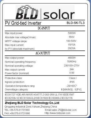
4 age 4 of 26 Copy of marking plate: Rating label:

5 age 5 of 26 Cautioning label:
6 age 6 of 26 Test item particulars... : Classification of installation and use... : Class I Supply Connection... : Input: Connector Output: Connector rotection against ingress of water...: I65 Mass of equipment [kg]... : Max. 19Kg for BLD-3K-TL3;BLD-3.5K-TL3; BLD-4K- TL3; BLD-5K-TL3 ossible test case verdicts: - test case does not apply to the test object... : N/A - test object does meet the requirement... : (ass) - test object does not meet the requirement... : F (Fail) Testing... : Date of receipt of test item... : Date (s) of performance of tests... : to General remarks: The test results presented in this report relate only to the object tested. This report shall not be reproduced, except in full, without the written approval of the Issuing testing laboratory. "(see Enclosure #)" refers to additional information appended to the report. "(see appended table)" refers to a table appended to the report. Throughout this report a comma / point is used as the decimal separator. Determination of the test result includes consideration of measurement uncertainty from the test equipment and methods. All tests were performed and the most unfavourable test results are recorded. Name and address of factory (ies): Zhejiang BLD Solar Technology CO., LTD. Qinggang Industrial Zone, Yuhuan, , Zhejiang rovince,.r.china General product information: The roduct was tested to the standard DIN VDE : The Solar converter converts DC voltage into AC voltage. The grid type inverters type BLD-3K-TL3; BLD-3.5K-TL3; BLD-4K-TL3 and BLD-5K-TL3 are single-phase solar-power inverters. They are responsible for converting the direct current generated by photovoltaic panels into single phase 230V, 50 Hz alternative current for deliver into the electrical power distribution grid. The inverter only operates when it is connected to the electrical utility grid and cannot operate as a standalone unit or in case of AC grid disruption. Between the inverter and AC grid there has to be a 20A circuit breaker for models BLD-3K-TL3 and BLD- 3.5K-TL3; Between the inverter and AC grid there has to be a 25A circuit breaker for models BLD-4K-TL3; Between the inverter and AC grid there has to be a 32A circuit breaker for model BLD-5K-TL3. The safety of the unit relies on the branch circuit of building installation. If used on a branch circuit greater

7 age 7 of 26 than this, additional testing may be necessary. The unit is approved for TN mains connections and IEC overvoltage category III. The equipment has been evaluated for use in a ollution Degree III (reduction to pollution degree II because of enclosure I 65.) and overvoltage category III environment and a maximum altitude of 2000m according to IEC The unit is specified for outdoor and indoor (unconditioned) use. The input and output are protected by Varistors to Earth. The unit is providing EMC filtering at the output toward mains. The unit does not provide galvanic separation from input to output (transformer-less type). The output is switched off redundant by the high power switching bridge and a dual Switch relays. This assures that the opening of the output circuit will also operate in case of one error. The anti-islanding function in this unit is carried out by the frequency-shifting method. The internal control is redundant built. It consists of two Microcontrollers Main CU (U2) and Slave CU (U8). The Main CU (U2) control the relays by switching signals, sample the V voltage, current and the bus voltage, measures AC voltage that before and after the relays, grid frequency, AC current with injected DC and the array insulation resistance to ground. In addition it tests the current sensors and the RCMU circuit before each start up. The Slave Main CU (U8) is using for sample the single phase grid voltage and current, detect inverter internal and heatsink s temperature, communicate and compare sample signals deviation with Main CU (U8) each other, it also can switch off the relays independently. The unit provides dual Switch relays in single phase inverter.the relays are tested before each start up. In addition the power bridge can be stopped by both CU, alarm an error code in display panel, another redundant relay provides basic insulation maintained between the V array and the mains. All the relays are tested before each start up. Block diagrams Models BLD-3K-TL3; BLD-3.5K-TL3 and BLD-4K-TL3,BLD-5K-TL3 Model difference: The models BLD-3K-TL3; BLD-3.5K-TL3 and BLD-4K-TL3 are identical with model BLD-5K-TL3 in hardware and just derated power by software; The product was tested on: hardware version: V1.00 software version: V1.00
8 age 8 of 26 DIN V VDE V Clause Requirement - Test Result - Remark Verdict 4 Requirements The following requirements applied to integrated and separated safety disconnect device. The disconnection device must disconnect the generator unit from the grid on the AC side with two switches in series due to - Voltage-and/or frequency change of low voltage network - DC current feed-in into the low voltage network - Unintended island operation - Intended island operation with standby network generator. 4.1 Functional safety The safety of the functions of automatic disconnection device defined in 4.3 to 4.6 and 4.8, if applicable, shall be ensured under all operation conditions. It can be installed as independent device or integrated parts of generation system and must be disconnect in single fault condition and indicate the fault condition Single fault safety The disconnection device must fulfill the requirement of single fault safety according to VDE-AR-N 4105: , A Disconnection device The disconnection device must comply with DIN EN (VDE ): , in case of integration in a V converter and VDE-AR-N 4105: , 6.4 in other cases. 4.2 Connection condition The connection, which reconnect after a network fault and reconnect after short interruption, shall comply with VDE-AR-N 4105: , Voltage monitoring Voltage decrease U< The disconnection due to a voltage decrease must comply with VDE-AR-N 4105: , and Voltage increase U>> The disconnection due to a voltage increase must comply with VDE-AR-N 4105: , and Slow voltage increase U> The disconnection due to a slow voltage increase (10- minute-mean-value) must comply with VDE-AR-N 4105: , and Frequency monitoring
9 age 9 of 26 DIN V VDE V Clause Requirement - Test Result - Remark Verdict The disconnection due to a frequency decrease or a frequency increase must comply with VDE-AR-N 4105: , und DC current monitoring A DC current feed into the low voltage network due to a disorder system operation must activate the disconnection within 0.2s. For this, the disorder itself or a measured DC component of current of more than 1A can be regarded as disconnection criterion. 4.6 Detection of islanding operation The disconnection due to the detection of a unintended islanding operation must comply with VDE-AR-N 4105: , and Marking A generation with automatic disconnection device must include with visible specification VDE It can be done through - Rating plate or - Issue on the brochure of disconnection or - A separate labelling 4.8 Requirement for the integrated disconnection device in photovoltaic converter The requirement of DIN EN (VDE ): , 4.8 for the residual current monitoring and for the isolation monitoring of V generators must be complied. See safety report: EFSH IE-01- L02 5 General requirements The limits of radio interference shall comply with DIN EN (VDE ). The interference immunity are tested according to DIN EN (VDE ) See EMC report: ACWE-E Type test General If not specified in other cases, the following tests are applied for integrated and separated disconnection device. A separate disconnection device is tested together with a suitable input feeder Here it is to ensure, that the disconnection signal generate not from input feeder but from the disconnection device. 6.1 Functional safety The test on single fault safety and fault detection with followed disconnection shall comply with DIN V DIN VDE V (VDE V ): , Voltage monitoring (Translator note: (should be related to 4.2: Connection condition)) The tests of connection are re-connection shall comply with DIN V DIN VDE V (VDE V ): , and Voltage monitoring
10 age 10 of 26 DIN V VDE V Clause Requirement - Test Result - Remark Verdict The test of voltage monitoring shall comply with DIN VDE V (VDE V ): , Frequency monitoring The test of frequency monitoring shall comply with DIN VDE V (VDE V ): , DC current monitoring The test of disconnection due to DC current feed in is done optionally according to a) or b): a) In the measurement device of disconnection device (e.g. current transducer, resistor), a DC current of 1A is impressed. The disconnection must be done within 0.2s. b) Through fault simulation and by means of measurement, it is determined whether a disordered system operation with a DC component of feed in current of more than 1A will lead to disconnection within 0.2s. 6.6 Detection of island operation The test on disconnection due to unintended islanding operation shall comply with DIN VDE V (VDE V ): , roduction test Before shipment of automatic disconnection device, each manufacturer shall undertake the production test in sense of safety related parameter. 8 Installation specifications Initial and repeated test of automatic disconnection device besides the production test can be waived. If the automatic disconnection device is installed as independent device, it shall not used in TN-C system. It is accepted for TN-C-S system in the case.
11 age 11 of Functional safety ambient temperature ( C) : 25 No. test component test fuse fuse current fault voltage No. time No. (A) (V) result Model: BLD-5K-TL3 1 R121 OC min - < 3A Can not start, fault 2 C88 SC min - < 3A Can not start, fault 3 C89 SC min - < 3A No abnormal phenomenon observed 4 R144 SC/OC min - < 3A Can not start, fault 5 C93 SC min - < 3A Can not start, fault 6 R143 OC min - < 3A No abnormal phenomenon observed 7 R140 OC min - < 3A Can not start, fault 8 R187 SC/OC min - < 3A Can not start, fault 9 R76 SC min - < 3A Can not start, no hazard 10 R76 OC min - < 3A Normal work, current monitor value double, no hazard 11 R81 OC min - < 3A No abnormal phenomenon observed 12 R87 SC/OC min - < 3A Can not start, fault 13 C61 SC min - < 3A Can not start, no hazard 14 RY2 SC min - < 3A Can not start, fault 15 R92 OC min - < 3A Can not start, fault 16 C64 SC min - < 3A Can not start, fault 17 C62 SC min - < 3A No abnormal phenomenon observed 18 R101 OC min - < 3A No abnormal phenomenon observed 19 R106 SC min - < 3A Can not start, fault 20 R115 OC min - < 3A Can not start, fault 21 R46 OC min - < 3A Can not start, no hazard 22 C44 SC min - < 3A Can not start, no hazard 23 R45 OC min - < 3A No abnormal phenomenon observed 24 TX1,TX2 SC min - < 3A Can not start, no hazard 25 C40 SC min - < 3A Can not start, no hazard 26 D10 SC min - < 3A Can not start, no hazard 27 R59 OC min - < 3A Can not start, no hazard 28 C17 SC min - < 3A Can not start, no hazard
12 age 12 of C20 SC min - < 3A Can not start, fault 30 R30 SC/OC min - < 3A No abnormal phenomenon observed 31 R33 SC min - < 3A Can not start, fault 32 R2 SC/OC min - < 3A Can not start, no hazard 33 R148 OC min - < 3A Can not start, no hazard 34 L-N output Overload min - < 3A The max. deliver output power was limited to 5212VA by the inverter itself, not possible to overload, no excessive temperature rise, no hazard 35 L-N SC min - < 3A Inverter shutdown due to loss of grid voltage, short circuit peak current < 200A 36 L to earth SC min - < 3A External circuit breaker open, Inverter shutdown due to loss of grid voltage, short circuit peak current < 200A 37 N to earth SC min - < 3A External circuit breaker open, Inverter shutdown due to loss of grid voltage, short circuit peak current < 200A 38 DC input Reverse polarity hours - < 3A Feed in max. V array short circuit current, until steady state, no excessive temp. rise; no hazard 39 CB SC Refer to above, component single fault test 40 Transform er SC Refer to item 24 & 67 supplementary information SC : short-circuit OC : open-circuit See technical documentation Disconnection switch The interface switch consists of two electrical break devices connected in series and is therefore designed with redundancy. Functional safety for the test for single-fault tolerance and fault finding with subsequent disconnection for the entire functional chain. An all-pole galvanic break device is provided. For synchronous machines, the break device for synchronisation is designed three pole instead of four pole.
13 age 13 of Setting values of the NS protection: Connecting conditions and synchronisation Model: BLD-5K-TL3 Setting Treconnection 60s [s]: Setting f< [Hz]: Setting f> [Hz]: Setting V< [V]: 60s 47,5Hz 51,5Hz 184V Setting V>> [V]: 264,5V fist Reset time: Limit: Connecting conditions for frequencies: a) <47,45 Hz No reconnection No resetting allowed Switch to: b) 47,45 Hz 79,7s 60 s c) >50,10 Hz No reconnection No resetting allowed Switch to: d) 50,10 Hz 70,0s 60 s Connecting conditions for voltages: e) <84% No reconnection No resetting allowed Switch to: f) 84% 70,1s 60 s g) >111 % No reconnection No resetting allowed Switch to: h) 111% 70,0s 60 s
14 age 14 of Setting values of the NS protection: Short interruption Model: BLD-5K-TL3 Setting T disconnection 5s [s]: Setting T reconnection 60s [s]: Setting V< [V]: 60s 60s 184V Step 1: Step 2: Step [V to V] 230 V to 177,1 V 230 V to 177,1 V Jump Duration [s]: 2 s 4 s Limit [s]: 5 s 60 s Reconnection Time [s]: 14,3s 74,4s Test: After providing evidence of a short interruption the network voltage is reduced from the nominal voltage with a surge of 77% U n. A surge to the nominal voltage takes place after 2 s. After providing evidence of a short interruption the network voltage is reduced from the nominal voltage with a surge of 77% U n. A surge to the nominal voltage takes place after 4 s. A short interruption is characterised by exceeding or not reaching the NS protection settings for the network frequency and/or network voltage for a maximum period of 3 seconds. A ramp of 10% n is not necessary after short interruptions. Limit values: Short interruption 2 s Reset time 5 s Short interruption 3 s Reset time 60 s 4.3 Voltage control Model: BLD-5K-TL3 Integrated NS protection three phase 30kVA (phase to neutral) Setting values of the NS protection: Operating time of the monitoring device: L to N: Setting U< [V]: 184 Setting U>> [V]: 264,5 Setting T disconnection [ms] 120 Under voltage: Over voltage: Step [V to V]: 230,0 V to 177,1 V 230,0 V to 271,4 V Limit [V]: 184,0 V 264,5 V Measurement [V:] 182,1 182,1 182,1 264,5 264,5 264,5 Limit [ms]: 200 ms 200 ms Disconnection time [ms]: 145,8 140,0 142,1 147,0 145,0 143,8 Test: The voltages per phase conductor are measured, into which current is fed between the line conductor and the neutral conductor. To measure the disconnection time a surge of 77%n is taken from the nominal voltage and of 118%n from the nominal voltage for undervoltage and undervoltage.
15 age 15 of 26 The permitted tolerance between setting value and trip value of the voltage may not exceed ± 1% of Un. Limit values: Voltage drop protection U<0,8 Un 200 ms Rise-in voltage protection U>>1,15 Un 200 ms 4.3 Measuring the rise-in voltage protection as a running 10-minute mean value Model: BLD-5K-TL3 Disconnection time: Limit: The voltage is set to 100% Un and held for 600 s. Thereafter the voltage is set to 112% Un. Disconnection must take place within 600 s. a) b) c) hase 1: 549,6s hase 2: - hase 3: s The voltage is set to U n for 600 s and then to 108% U n for 600 s. No disconnection should take place. hase 1: No disconnection hase 2: - hase 3: - The voltage is set to 106 % U n and held for 600 s. Thereafter the voltage is set to 114 % U n. *The disconnection should last for half the period as in oint a) hase 1: 310,6s hase 2: - hase 3: - Disconnection should not take place. 300 s Test: a) This test serves as proof of the measurement accuracy and the maximum set time. b) This test serves as proof of the measurement accuracy. c) This test serves as proof of the correct formation of the 10 minute running mean value. The permitted tolerance between setting value and trip value of the voltage may not exceed ± 1 % of U n. Limit values: Rise-in voltage protection U>1,1 U n after a max. 600 s, the switch off after 200 ms. If only one integrated NS protection is used for the power generation systems 30kVA, the value of the risein voltage protection U> of 1,1 U n may not be changed.
16 age 16 of Setting values of the NS protection: Frequency measurement Model: BLD-5K-TL3 Operating time of the monitoring device Setting f< [Hz]: 47,5 Setting f>[hz]: 51,5 Setting T disconnection [ms] 120 Under frequency Over frequency Ramp [Hz to Hz]: 48,00 Hz -> 47,00 Hz 51,00 Hz -> 52,00 Hz Limit [Hz]: 47,50 Hz 51,50 Hz Measurement [Hz]: 47,50 47,50 47,50 51,51 51,51 51,51 Limit [ms]: 200 ms 200 ms Disconnection time [ms]: 65,8 65,8 65,8 60,4 60,4 60,4 The measuring is performed at a continuous change of frequency of 1 Hz/s. The trip value was determined manually by reducing the frequency in 10 mhz steps. When the trip value is known (e.g. 47,50 Hz), the grid simulator is programmed to run from e.g. 48,00 Hz to 47,00 Hz with 1 Hz/s. The disconnection time is calculated by the measured time minus the 500 ms from 48,00 Hz to 47,50 Hz. The setting value and the trip value of the frequency may not vary by more than ±0.1 % f n. For frequencies of between 47,5 Hz and 51,5 Hz (±0,1% f n ) automatic disconnection from the network as a result of a deviation in frequency is not permitted. Limit values: Frequency decrease protectionf<47,5 Hz Frequency increase protectionf<51,5 Hz 200 ms 200 ms
17 age 17 of TABLE: Monitoring the DC current Model BLD-5K-TL3 V Input 1 V Input L1-N Trip value measured (ma) Trip time measured (ms) A - 1 A Measured 1A 79,0 81,0 93,5 92,5 70,5 80,0 Trip limit 1A 200 ms Reconnection time measured 60,0s Reconnection time limited > 30 s 4.6 Test condition: Disconnection limit: Output power Osc. parameter Test of the resonance circuit Model: BLD-5K-TL3 Frequency: 50+/-0,01 Hz UN = 230+/-1% Vac RLC consumes inverter real power within +/-3% Distortion factor of chokes <3% Quality Q>2 5 s 25% 50% 100% - 5% 0,160s 0,420s 0,320s - 4% 0,455s 0,425s 0,330s - 3% 0,265s 0,440s 0,340s - 2% 0,405s 0,200s 0,305s - 1% 0,360s 0,365s 0,305s 0% 0,295s 0,300s 0,322s +1% 0,255s 0,285s 0,305s +2% 0,235s 0,240s 0,295s +3% 0,225s 0,255s 0,297s +4% 0,225s 0,240s 0,237s +5% 0,245s 0,245s 0,277s arameter at 0% L= mh R=Ω 102,8 51,38 25,69 64,53 32,27 16,13 C=μF 99,00 197,00 395,00 Test: The capacitors and the chokes of the resonant circuit were adjusted in order to reach a quality of >2. QC+QL=-Q,WR. The resistors of the resonant circuit consumed the real power of the inverter (WR) within +/-3%. Limit values: Quality factorq> 2 Disconnectiont 5 s

18 age 18 of 26 Appendix 1: -Enclosure-Bottom -Enclosure-Bottom

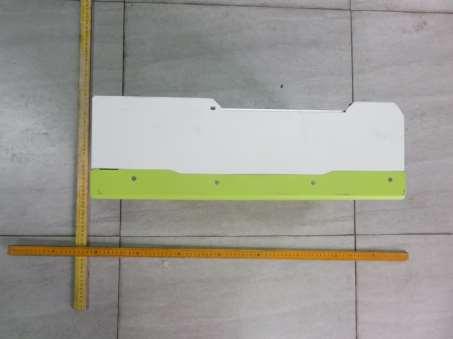
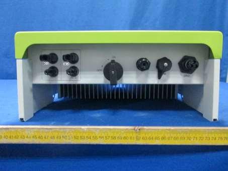
19 age 19 of 26 -Enclosure-side1 -Enclosure-side2

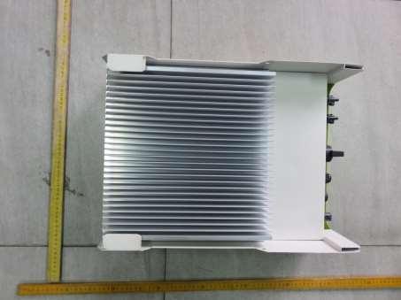
20 age 20 of 26 -Enclosure-Top -Enclosure-Rear
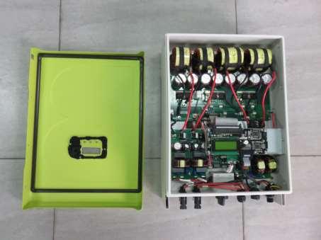
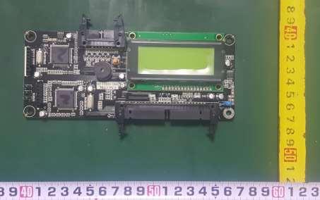
21 age 21 of 26 -Enclosure-Internal -Main board- Components side


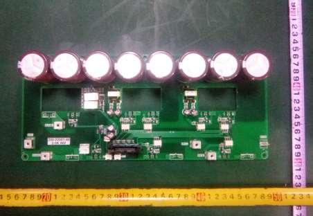
22 age 22 of 26 - Main board-solder side I/O board- Components side

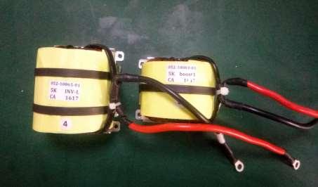
23 age 23 of 26 -I/O board-solder side -Choke
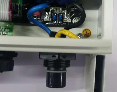
24 age 24 of 26 -Enclosure-Front -Display board- Components side


25 age 25 of 26 - Display board-solder side - communication board- Components side

26 age 26 of 26 - communication board-solder side ************************************************* End of Report********************************************
TEST REPORT DIN V VDE V
 Test Report issued under the responsibility of: TEST REORT DIN V VDE V 0126-1-1 Report Number....: EFSH16041203-IE-01-L12 Date of issue...: 2016-11-28 Total number of pages... 25 pages Testing Laboratory...
AS/NZS AS/NZS
 TEST REORT AS/NZS 4777.2 AS/NZS 4777.3 Grid connection of energy systems via inverters Grid protection requirements Report reference number... : 13TH0287-AS/NZS 4777_0 Date of issue......: 2014-01-22 Total
ZHEJIANG MAXGE ELECTRIC TECHNOLOGY CO., LTD. Address... :
 Test Report issued under the responsibility of: TEST REORT IEC 60898-1 Circuit-breakers for over current protection for household and similar installations art 1 - Circuit-breakers for a.c. operation Report
Dycon D1532SM. EN50131/PD6662 Grade 3, 12V 2A Power Supply. Technical Description Installation and Operating Manual DYCON POWER SOLUTIONS LTD
 Dycon D1532SM EN50131/PD6662 Grade 3, 12V 2A Power Supply Technical Description Installation and Operating Manual DYCON POWER SOLUTIONS LTD Tel: +44 (0)1443 471 900 Unit A Cwm Cynon Business Park Mountain
TEST REPORT IEC Information technology equipment Safety Part 1: General requirements
 Test Report issued under the responsibility of: TEST REPORT IEC 60950-1 Information technology equipment Safety Part 1: General requirements Report Number.... : 1510050STO-001 Date of issue... : 26 October
Certificate of Conformity self-generation unit
 Seite 1 von 7 Certificate of Conformity self-generation unit Manufacturer / applicant: SMA Solar Technology AG Sonnenallee1 34266 Niestetal Germany Type of power generation unit: Active power (nominal
DEVICE STATE/BYPASSED FAILURE OVERLOAD
 Technical specifications Type 5. 7. Control electronics Rated values Terminal Rated control supply voltage A1A2 V AC 115 230 115 230 Tolerance % -15+10-15+10 Rated control supply STANDBY ma 15 15 Rated
TEST REPORT IEC Information technology equipment Safety Part 1: General requirements
 Test Report issued under the responsibility of: TEST REPORT IEC 60950-1 Information technology equipment Safety Part 1: General requirements Report Number.... : 31282706.003 Date of issue... : 22 nd March,
Dycon D2430 EN54-4 Fire Alarm Power Supply Series
 Dycon D2430 EN54-4 Fire Alarm Power Supply Series Technical Description Installation and Operating Manual Construction Product Regulation 0359-CPR-00434 Page 1 of 14 Contents 1. General... 3 1.1 Product
TEST REPORT IEC Low-voltage switchgear and control gear Part 7-4: Ancillary equipment PCB terminal blocks for copper conductors
 r Test Report issued under the responsibility of: TEST REORT Low-voltage switchgear and control gear art 7-4: Ancillary equipment CB terminal blocks for copper s Report Number.... : 2169331.75 Date of
RE-PR3-E-86&105 3-Phase Panel Mount 86 and 105kW
 Page 1 of 6 3-Phase Panel Mount 86 and 105kW Features: Benefits: 0-10Vdc, 0-5Vdc, 4-20mA or manual via potentiometer control input Over temperature protection with auto reset Enclosed panel mounting Efficient
Test Result No.1. Lead (Pb) % ND See comment if > % Cadmium (Cd) % ND Mercury (Hg) % ND
 % ND See comment if > % Cadmium (Cd) % ND Mercury (Hg) % ND") Reference No.: WTF16F0961094C age 2 of 5 Test Results: Test Item(s) Unit Test Result No.1 MDL Maximum Allowable Limit Lead (b) % ND 0.0002 See comment if > 0.004 % Cadmium (Cd) % ND 0.0002 0.002 Mercury
Reference No.: WTF16F0961094C age 2 of 5 Test Results: Test Item(s) Unit Test Result No.1 MDL Maximum Allowable Limit Lead (b) % ND 0.0002 See comment if > 0.004 % Cadmium (Cd) % ND 0.0002 0.002 Mercury
Increased requirements on external DC-breakers for transformerless PV inverters in Australia
 Increased requirements on external DC-breakers for transformerless PV inverters in Australia Are the requirements also expedient for PV plants with transformerless SMA PV inverters? Content The standard
Manual. BlueSolar Grid Inverter 1500 / / / / / 230
 Manual EN BlueSolar Grid Inverter 1500 / 230 2000 / 230 2800 / 230 4000 / 230 5000 / 230 Before you start This manual contains important information regarding installation and safe operation of this unit.
TEST REPORT IEC Information technology equipment Safety Part 1: General requirements
 Test Report issued under the responsibility of: TEST REPORT IEC 60950-1 Information technology equipment Safety Part 1: General requirements Report Number.... : 221868-CI3-2 CB DE1-56824 Date of issue...
LVD TEST REPORT EN : 2006+A12: MEASUREMENT AND TEST REPORT For. Ingtron Enterprise Co., Ltd.
 LVD TEST REORT EN 60950-1: 2006+A12: 2011 MEASUREMENT AND TEST REORT For Ingtron Enterprise Co., Ltd. No. 211-1, Qingfeng Road, Qingxi Town, Dongguan City, Guangdong, China Model: reference page 2 Feb.
TEST REPORT IEC Information technology equipment Safety Part 1: General requirements
 Test Report issued under the responsibility of: TEST REPORT IEC 60950-1 Information technology equipment Safety Part 1: General requirements Report Number.... : 207809-CI3-3 CB DE1-9640/A2 Date of issue...
Manual for Inverter system type PCI05
 - 1- Manual for Inverter system type PCI05 SAFETY INSTRUCTIONS This manual must be read before installation, use or work on the product. This product contains dangerous voltages that when touched can cause
TANZANIA BUREAU OF STANDARDS
 EDC 5 (5235) P3 Mini-Grid Systems DRAFT TANZANIA STANDARD (Draft for comments only) Part 2: Application of Inverters TANZANIA BUREAU OF STANDARDS TBS 2017 First Edition 2017 T able of content 1 2 3 4 5
TEST REPORT IEC Information technology equipment Safety Part 1: General requirements
 Test Report issued under the responsibility of: TEST REPORT IEC 60950-1 Information technology equipment Safety Part 1: General requirements Report Number.... : 1510053STO-001 Date of issue... : 2 November
Page 2 of 6. Summary of testing The clause 17 and clause 29 are considered and check on the appliance.
 12012453 003 age 2 of 6 Summary of testing The clause 17 and clause 29 are considered and check on the appliance. Test items particulars Serial umber... : rototype samples Additional information... : (.A.)...
Application. Battery. Public Grid GS HYBRID INVERTER
 GS HYBRID SOLAR INVERTER Feed from Solar and Power, Grid backup, Build-in Transfer Switch / Solar Charger/ AC Charger, 500W~3kW, Pure Sine Wave Output GSH-15XX and GSH-30XX are the ideal solutions for
World Class Power Solutions. Rectifiers. For Stationary Battery Systems in Nuclear Power Plants
 World Class Power Solutions Rectifiers For Stationary Battery Systems in Nuclear Power Plants General 2 1.1 Application Electronically controlled rectifier assemblies are used in conjunction with suitable
Phoenix Inverter
 Manual EN Handleiding NL Manuel FR Anleitung DE Manual ES Appendix Phoenix Inverter 12 250 12 375 12 500 12 800 24 250 24 375 24 500 24 800 48 250 48 375 48 500 48 800 1. Safety instructions WARNING: ELECTRIC
Date Issued: 10 August 2009 Status: ISSUED Review Date: 10 August 2011 Ref: NS5.3 DISTRIBUTED GENERATION TECHNICAL REQUIREMENTS TABLE OF CONTENTS
 Date Issued: 10 August 2009 Status: ISSUED Review Date: 10 August 2011 Ref: NS5.3 DISTRIBUTED GENERATION TECHNICAL REQUIREMENTS TABLE OF CONTENTS 1. PURPOSE AND SCOPE OF THIS DOCUMENT... 3 2. DEFINITIONS...
Emergency lighting units EM converterled
 EM converter EM converter BASIC icd/imh 250 V BASIC series Product description lighting Driver for manual testing For self-contained emergency lighting For modules with a forward voltage of 50 250 V ow
8 Troubleshooting and Maintenance
 8 Troubleshooting and Maintenance 8.1 Troubleshooting 8.1.1 Troubleshooting of LED Indicators See Tab. 7-4 State Descriptions of LED Indicators for the definition. Fault Type LED indicators and LCD screen
Industrial Power Supplies
 , Features Switch Mode Power Supplies for DIN-rail Mounting 6 Power Ranges with 2, 3, 6, 12, 20 and 24 A Current (24 VDC Models) Selectable 115/ 230 VAC Input Very low Ripple and Noise EMI complies with
Emergency lighting units EM converterled
 EM converter EM converter BASIC icd 50 V BASIC series Product description lighting Driver for manual testing For self-contained emergency lighting For modules with a forward voltage of 10 54 V SEV for
TEST REPORT IEC Information technology equipment Safety Part 1: General requirements
 Test Report issued under the responsibility of: TEST REPORT IEC 60950-1 Information technology equipment Safety Part 1: General requirements Report Number.... : 16059155 001 Date of issue... : Apr.24,
Emergency lighting units EM converterled. EM converterled BASIC 50 V BASIC series
 BASIC 50 V BASIC series Product description lighting Driver for manual testing For self-contained emergency lighting For modules with a forward voltage of 10 52 V SEV for output voltage < 60 V DC ow profile
Page 2 of 23 UNT150420C11
 Page 2 of 23 UNT150420C11 United Nations, Recommendations on the Transport of Dangerous Goods, Manual of Test and Criteria (Rev. 5 th, Amendment 2), Section 38.3 Report Reference No.... : Compiled by...
SPECIFICATIONS UPS Triple Output 13.6VDC/213W, 48VDC/153W, 48VDC/39W
 Page 1 / 7 Full operation without need of battery Two independent 48Vdc outputs for switching and control Local monitoring with 8 LEDs Remote monitoring with 4 alarm relays Monitoring and configuration
INTERCONNECTION STANDARDS FOR PARALLEL OPERATION OF SMALL-SIZE GENERATING FACILITIES KILOWATTS IN THE STATE OF NEW JERSEY
 INTERCONNECTION STANDARDS FOR PARALLEL OPERATION OF SMALL-SIZE GENERATING FACILITIES 10-100 KILOWATTS IN THE STATE OF NEW JERSEY January 1, 2005 Rockland Electric Company 390 West Route 59 Spring Valley,
TEST REPORT IEC Part 1: General requirements for basic safety and essential performance
 jhćmtc Test Report issued under the responsibility of: TEST REPORT IEC 60601-1 Part 1: General requirements for basic safety and essential performance Report Number.... : T223-0128/16 Date of issue...
Output Current Input Current Reflected Ripple. VDC VDC ma ma(typ.) ma(typ.) ma(typ.) VDC μf %
 ma(typ.) ma(typ.) VDC μf %") FEATURES Industrial Standard Quarter Brick Package Wide Input Range 43-101VDC & 66-1VDC Excellent Efficiency up to 92% I/O Isolation 3000VAC with Reinforced Insulation Operating Ambient Temp. Range - C
FEATURES Industrial Standard Quarter Brick Package Wide Input Range 43-101VDC & 66-1VDC Excellent Efficiency up to 92% I/O Isolation 3000VAC with Reinforced Insulation Operating Ambient Temp. Range - C
Testing Laboratory...: TÜV Rheinland Taiwan Ltd., Taichung Laboratory. Address...: 10F, No.219, Min Chuan Road, Taichung 403, Taiwan.
 11009797 002 age 1 of 11 TEST REORT Flat non-rewirable two-pole plugs, 2.5 A 250 V, with cord, for the connection of class II - equipment for household and similar purposes Report Reference No....: 11009797
EPS/ELA-Series User Manual EPS/ELA 250W
 EPS/ELA-Series User Manual EPS/ELA 250W EPS Stromversorgung GmbH Tel: +49 (0)821 570451 0 Index 3 Page: 1 Table of contents: Page 1. Features of ELA-Series... 3 1.1 Basic Functions... 3 1.2 Options...
Emergency lighting units EM converterled
 EM converter EM converter BASIC MH/iFePO4 250 V BASIC series Product description Self contained emergency lighting Driver for manual testing For modules with a forward voltage of 50 250 V ow profile casing
Emergency lighting units EM converterled. EM converterled BASIC 200 V BASIC series
 EM converter EM converter BASIC 200 V BASIC series Product description lighting Driver for manual testing For modules with a forward voltage of 50 200 V ow profile casing (21 x 30 mm cross-section) For
.3 Section Waste Management and Disposal.
 Issued 2005/06/01 Section 16261 Uninterruptible Power Systems Static Page 1 of 10 PART 1 GENERAL 1.1 RELATED SECTIONS.1 Section 01330 Submittal Procedures..2 Section 01780 Closeout Submittals..3 Section
Application Engineering
 Application Engineering February, 2009 Copeland Digital Compressor Controller Introduction The Digital Compressor Controller is the electronics interface between the Copeland Scroll Digital Compressor
Matrix APAX. 380V-415V 50Hz TECHNICAL REFERENCE MANUAL
 Matrix APAX 380V-415V 50Hz TECHNICAL REFERENCE MANUAL WARNING High Voltage! Only a qualified electrician can carry out the electrical installation of this filter. Quick Reference ❶ Performance Data Pages
Emergency lighting units EM converterled. EM converterled BASIC 90 V BASIC series
 BASIC 90 V BASIC series Product description lighting Driver for manual testing For self-contained emergency lighting For modules with a forward voltage of 40 97 V SEV for output voltage < 120 V DC ow profile
Emergency lighting units EM converterled
 BASIC MH/iFePO4 250 V BASIC series Product description Self contained emergency lighting Driver for manual testing For modules with a forward voltage of 50 250 V ow profile casing (21 x 30 mm cross-section)
9.1.4 Troubleshooting of Faults in LCD Screen
 User Manual 9 and Maintenance 9.1.2 Arc Detection Self-test An auto-test circuit is included in the module design of the inverter s AFDI function. If a DC arc fault is detected, the corresponding fault
STOREDGE TM. SolarEdge Single Phase StorEdge TM Solutions for North America SolarEdge StorEdge Solutions Benefits:
 SolarEdge Single Phase StorEdge TM Solutions for North America 12-25 STOREDGE TM SolarEdge StorEdge Solutions Benefits: More Energy - DC-coupled architecture stores PV power directly to the battery without
020: 2013 CEB SPECIFICATION MINIATURE CIRCUIT BREAKER (MCB)
") 020: 2013 CEB SPECIFICATION MINIATURE CIRCUIT BREAKER (MCB) CEYLON ELECTRICITY BOARD SRI LANKA Telephone: +94 11 232 0953 Fax: +94 11 232 3935 CONTENTS Page 1.0 Scope 3 2.0 System Parameters 3 3.0 Service
020: 2013 CEB SPECIFICATION MINIATURE CIRCUIT BREAKER (MCB) CEYLON ELECTRICITY BOARD SRI LANKA Telephone: +94 11 232 0953 Fax: +94 11 232 3935 CONTENTS Page 1.0 Scope 3 2.0 System Parameters 3 3.0 Service
RE-PR1-F 1-Phase Din-Rail Mount 1.5, 3 & 6kW
 Page 1 of 5 RE-PR1-F 1-Phase Din-Rail Mount 1.5, 3 & Features: Benefits: 0-10Vdc or 0-5Vdc control input Over temperature protection with auto reset Din-rail mounting Efficient electronic switching No
Eaton 93PS 8-40kW UPS Technical Specification Manufacturer s declaration in accordance with IEC
 Manufacturer s declaration in accordance with 8- Frame Model catalogue reference 93PS-XX(20)-YY- 93PS-XX(40)-YY- Number of power modules (UPM) 1 1 or 2 Number of internal batteries 0 to 2 x 32 blocks 0
SINAMICS SM150. 4/2 Overview. 4/2 Benefits. 4/2 Design. 4/6 Function. 4/8 Selection and ordering data. 4/8 Options
 /2 Overview /2 Benefits /2 Design /6 Function /8 Selection and ordering data /8 Options Technical data /1 General technical data /15 Control properties /15 Ambient conditions /16 Installation conditions
R series solar charger inverter 1000W to 6000W
 R series solar charger inverter 1000W to 6000W User s Manual Table of Contents: Figures of Unit......3 Line mode specification...3 Inverte mode specification......4 AC charge mode specification..5 Solar
Test Report issued under the responsibility of: Report Reference No... : AS9-7 Date of issue... : Total number of pages...
 Test Report issued under the responsibility of: TEST REORT EHA-DACH Testing Regulation Supplemental requirements for granting the international quality label for heat pumps Testing of Air/Water Heat umps
Emergency lighting units EM converterled
 BASIC MH/iFePO4 90 V BASIC series Product description Self contained emergency lighting Driver for manual testing For modules with a forward voltage of 40 97 V SEV for output voltage < 120 V DC ow profile
ABB PV + Storage REACT-3.6/4.6-TL 3.6 to 4.6 kw
 SOLAR INVERTERS ABB PV + Storage REACT-3.6/4.6-TL 3.6 to 4.6 kw REACT stores and allows to make the most of the energy produced by a residential photovoltaic system. 01 01 REACT-3.6/4.6-TL PV + Storage
CP Automatic capacitor bank
 CP 254 - Automatic capacitor bank STE-CP254_V2_général.doc Page 1 CP 254 - General presentation CP 254 is a range of MV capacitor banks designed to be used in electrical networks up to 36kV. The capacitor
TEST REPORT IEC Information technology equipment Safety Part 1: General requirements
 Test Report issued under the responsibility of: TEST REPORT IEC 60950-1 Information technology equipment Safety Part 1: General requirements Report Number.... : 207809-CI3-2 CB DE1-49619/A2/B1/M2 Date
MERU Solar Off-Grid Inverters
 1 kva / 2 kva Off-Grid Solar Inverters with LCD and LED displays 24 / 48 VDC battery versions for 1 kva and 48 VDC for 2 kva Pure sine wave with highest efficiency Fully configurable (PV / Grid priority
MAKING MODERN LIVING POSSIBLE. UniLynx Indoor Installation Manual. ULX 1800i ULX 3000i ULX 3600i ULX 5400i SOLAR INVERTERS
 MAKING MODERN LIVING POSSIBLE UniLynx Indoor Installation Manual ULX 1800i ULX 3000i ULX 3600i ULX 5400i SOLAR INVERTERS Contents Contents 1. Introduction 2 Introduction 2 Installation Sequence 2 Important
TEST REPORT IEC Connectors Safety requirements and tests
 IECEE OD-2020-F1:2017 IEC 2017 Ed.1.0 TRF Template 2017-05-17 Test Report issued under the responsibility of: TEST REORT Connectors Safety requirements and tests Report Number... : 250150-TL6-1 Date of
Technical Data Sheets
 GE Digital Energy Power Quality Technical Data Sheets Digital Energy Uninterruptible Power Supply SG-CE Series 60 80 100 120 kva PurePulse 400 Vac CE Series 1 SG-CE Series 100-120 kva PurePulse SG-CE Series
ABB PV + Storage REACT-3.6/4.6-TL 3.6 to 4.6 kw
 Solar inverters ABB PV + Storage REACT-3.6/4.6-TL 3.6 to 4.6 kw REACT stores and allows you to make the most of the energy produced by your photovoltaic system. REACT is an innovative photovoltaic inverter,
SLOVAK UNIVERSITY OF TECHNOLOGY Faculty of Material Science and Technology in Trnava ELECTRICAL ENGINEERING AND ELECTRONICS.
 SLOVAK UNIVERSITY OF TECHNOLOGY Faculty of Material Science and Technology in Trnava ELECTRICAL ENGINEERING AND ELECTRONICS Róbert Riedlmajer TRNAVA 2007 Unit 14 - Fundamentals of power system protection
Installation Couplers intended for permanent connection in fixed installation
 Test Report issued under the responsibility of: TEST REORT Installation Couplers intended for permanent connection in fixed installation Report Reference No....: 2167493.50-DCC Date of issue...: 2013-11-26
SYSDrive Frequency Inverter
 SYSDrive Frequency Inverter T V/f control T PID control T Standard LED, optional LCD operator T Fieldbus options: DeviceNet T 7 configurable digital inputs T 3 configurable digital outputs T Low audible
Technical Specifications. Sentinel PRO 700 VA up to 3000 VA 1000 VA ER-2200 VA ER-3300 VA ER
 Technical Specifications Sentinel PRO 700 VA up to 3000 VA 1000 VA ER-2200 VA ER-3300 VA ER Sentinel PRO CONTENTS 1. GENERAL DESCRIPTION... 2 1.1. Main features of the UPS unit... 3 1.2. Standard Versions...
Application Engineering
 Application Engineering March 2011 Copeland Digital Compressor Controller Introduction The Digital Compressor Controller is the electronics interface between the Copeland Scroll Digital compressor or the
TEST REPORT IEC Connectors Safety requirements and tests
 IECEE OD-2020-F1:2017 IEC 2017 Ed.1.0 TRF Template 2017-05-17 Test Report issued under the responsibility of: TEST REORT Connectors Safety requirements and tests Report Number... : 249955-TL6-1 Date of
Regenerative DC Common Bus Supply
 Regenerative DC Common Bus Supply The Regenerative DC Common Bus Supply supplies both motoring and regenerative current to the DC bus of one or more AC drives without the need of rectifier front end in
CP-250E-60/72-208/240-MC4 Microinverter with Modular Trunk Cable
 CP-250E-60/72-208/240-MC4 Microinverter with Modular Trunk Cable Chilicon Power Aug 2016 1 CONTENTS CP-250E Microinverter System... 3 The CP-100 Cortex Gateway... 3 Important Safety Information... 4 Inverter
TOWER MAXI T SINGLE CONVERSION ON LINE UPS SYSTEMS
 INSTRUCTION MANUAL TOWER MAXI T SINGLE CONVERSION ON LINE UPS SYSTEMS September 2000 TOWER UPS DISTRIBUTION (PTY) LTD 1 1. INTRODUCTION T A B L E O F C O N T E N T S 1.1 General Description... 3 1.2 Features...
Amendment to Test Report
 Test Report issued under the responsibility of www.nemko.com Amendment to Test Report This Amendment is valid only together with the main Test Report Report No.... : 277779 Main Report No.... : 246847
ABB central inverters ULTRA-750/1100/ kW to 1560kW
 Solar inverters ABB central inverters ULTRA-750/1100/1500 750kW to 1560kW * ABB s utility-scale ULTRA inverters combine high efficiency with a wide input voltage range and multiple maximum power point
Output Current Input Current Reflected Ripple. Efficiency (typ.) (Range) VDC VDC ma ma(typ.) ma(typ.) ma(typ.) VDC μf % MTQZ50-72S05
 (Range) VDC VDC ma ma(typ.) ma(typ.) ma(typ.) VDC μf % MTQZ50-72S05") Doc. EC-0094 FEATURES Industrial Standard Quarter Brick Package Wide Input Range 43-101VDC & 66-1VDC Excellent Efficiency up to 92% I/O Isolation 3000VAC with Reinforced Insulation Operating Ambient Temp.
Doc. EC-0094 FEATURES Industrial Standard Quarter Brick Package Wide Input Range 43-101VDC & 66-1VDC Excellent Efficiency up to 92% I/O Isolation 3000VAC with Reinforced Insulation Operating Ambient Temp.
Annex I Tested by (name + signature)...: Approved by (name + signature)...: Date of issue... : 22/11/2012. TUV RHEINLAND ITALIA S.r.l.
...: Approved by (name + signature)...: Date of issue... : 22/11/2012. TUV RHEINLAND ITALIA S.r.l.") TEST REORT Rotating electrical machines art 5: Degrees of protection provided by the integral design of rotating electrical machines (I code) Classification Report Reference No....: 28105442 002 Annex
TEST REORT Rotating electrical machines art 5: Degrees of protection provided by the integral design of rotating electrical machines (I code) Classification Report Reference No....: 28105442 002 Annex
TEST REPORT IEC Information technology equipment Safety Part 1: General requirements
 Test Report issued under the responsibility of: TEST REPORT IEC 60950-1 Information technology equipment Safety Part 1: General requirements Report Number... : 30581696.032 Date of issue... : 14 July 2015
Emergency lighting units EM converterled. EM converterled ST 50 V SELFTEST series
 ST 50 V SEFTEST series Product description lighting Driver with self-test function For self-contained emergency lighting For modules with a forward voltage of 10 52 V SEV for output voltage < 60 V DC ow
University of Houston Master Construction Specifications Insert Project Name SECTION ELECTRONIC VARIABLE SPEED DRIVES PART 1 - GENERAL
 SECTION 23 04 10 ELECTRONIC VARIABLE SPEED DRIVES PART 1 - GENERAL 1.1 RELATED DOCUMENTS: A. The Conditions of the Contract and applicable requirements of Division 1, "General Requirements", and Section
Regenerative Utility Simulator for Grid-Tied Inverters
 Regenerative Utility Simulator for Grid-Tied Inverters AMETEK s RS & MX Series with the SNK Option provides the solution Testing of grid-tied inverters used in solar energy systems is emerging as a major
Certificate of Conformity self-generation unit
 Seite 1 von 7 Certificate of Conformity self-generation unit Manufacturer / applicant: Type of power generation unit: SMA Solar Technology AG Sonnenallee 1 34266 Niestetal Germany Grid-tied photovoltaic
Certificate of Conformity self-generation unit
 Seite 1 von 7 Certificate of Conformity self-generation unit Manufacturer / applicant: Type of power generation unit: SMA Solar Technology AG Sonnenallee 1 34266 Niestetal Germany Grid-tied photovoltaic
RVS-AX Instruction Manual
 RVS-AX Analog Soft Starter 8-170A, 220-600V Instruction Manual Ver. 10/11/2009 2 Table of Content RVS-AX Instruction Manual 1. TABLE OF CONTENT 1. Table of Content...2 2. Safety & Warnings...3 2.1 Safety...3
Output Current Input Current Over Load VDC VDC ma ma(typ.) ma(typ.) VDC μf %
 ma(typ.) VDC μf %") Doc. EC-0093 FEATURES Industrial Standard 2"x1" Package Ultra-wide Input Range 9-36VDC, 18-75VDC, 40-160VDC I/O Isolation 3000VAC with Reinforced Insulation Operating Ambient Temp. Range -40 C to +88 C
Doc. EC-0093 FEATURES Industrial Standard 2"x1" Package Ultra-wide Input Range 9-36VDC, 18-75VDC, 40-160VDC I/O Isolation 3000VAC with Reinforced Insulation Operating Ambient Temp. Range -40 C to +88 C
Retrofit to Single phase / Three phase PV system Micro-grid, UPS, Peak shift, Pure off-grid retrofitting etc multi-working
 Retrofit to Single phase / Three phase PV system Micro-grid, UPS, Peak shift, Pure off-grid retrofitting etc multi-working mode for choice. Automatic, Zero Hybrid Switch Built-in Smart management control
Technical Data Sheets
 GE Consumer & Industrial Technical Data Sheets Digital Energy Uninterruptible Power Supply SG-CE Series 160 200 250 300 kva PurePulse TM 400 Vac CE Series 1 Date of issue: 15.02.2007 SGSE160-200S1UPS01
SolarMax 50TS/80TS/100TS/300TS. Ready for the future.
 SolarMax 50TS/80TS/100TS/300TS Ready for the future. Ready for the future. Sputnik Engineering commissioned the first SolarMax PV central inverter in 1992. Since then thousands of central inverters have
INSTALLATION INSTRUCTIONS FOR SYMCOM'S MODEL 777-HVR-SP ELECTRONIC OVERLOAD RELAY
 CONNECTIONS INSTALLATION INSTRUCTIONS FOR SYMCOM'S MODEL 777-HVR-SP ELECTRONIC OVERLOAD RELAY BE SURE POWER IS DISCONNECTED PRIOR TO INSTALLATION!! FOLLOW NATIONAL, STATE AND LOCAL CODES! READ THESE INSTRUCTIONS
Sola/Hevi-Duty S3K Series Mini-Tower UPS
 Sola/Hevi-Duty S3K Series Mini-Tower UPS GUIDE SPECIFICATIONS 700VA to 1600VA 120V models Single - Phase Uninterruptible Power Supply Systems 1.1 SUMMARY 1.0 GENERAL This specification defines the electrical
AC MODULE P72PCS-300W
 AC MODULE P72PCS-300W Features Industry leading module power output warranty International quality, safety and performance certifications High-reliability with guaranteed 0/+5 Wp peak power Manufacturing
User Manual Rittal PMC UPS 6kVA
 User Manual Rittal PMC UPS 6kVA Germany Rittal GmbH & Co. KG Auf dem Stützelberg D-35745 Herborn Tel.: ++49-27 72-5 05-0 Fax: ++49-27 72-5 05-23 19 Internet: www.rittal.de 26 Contents 1. Introduction...
EON Model EL3 Three Phase Centralized Emergency Lighting Inverter. General Specification 10KW 33KW Systems
 EON Model EL3 Three Phase Centralized Emergency Lighting Inverter General Specification 10KW 33KW Systems 1.0 GENERAL This specification defines the electrical and mechanical characteristics and requirements
Page 2 of 39 Report No. CTI PA Testing location:
 age 2 of 39 Report No. CTI A 2841-2 Tests performed (name of test and test clause): according to :2009: 5 - Interface characteristics, 6 Information, 7 - Service conditions, 10.2.3.3 - Verification of
SolarMax MT series The all-rounder for trade and industry
 SolarMax MT series The all-rounder for trade and industry All good things come in three phases. We have been developing and producing transformerless inverters for over 20 years. Our engineers have effectively
ELECTRICAL POWER, DIRECT CURRENT, SPACE VEHICLE DESIGN REQUIREMENTS
 MIL-STD-1539 (USAF) 1 AUGUST 1973 MILITARY STANDARD ELECTRICAL POWER, DIRECT CURRENT, SPACE VEHICLE DESIGN REQUIREMENTS FSC 1810 Electrical Power, Direct Current, Space Vehicle Design Requirements MIL-STD-1539
Lexium integrated drives
 Description ILp for CANopen, PROFIBUS DP, RS ILE with brushless DC motor Description ILE comprise control electronics with a fieldbus interface for CANopen DS, PROFIBUS DP or RS and a brushless DC motor.
013 : 2009 CEB SPECIFICATION MOULDED CASE CIRCUIT BREAKERS
 013 : 2009 CEB SPECIFICATION MOULDED CASE CIRCUIT BREAKERS FOR OVERHEAD NETWOKS CEYLON ELECTRICITY BOARD SRI LANKA Specification for MOULDED CASE CIRCUIT BREAKERS FOR OVERHEAD NETWOKS CEB Specification
Emergency lighting units EM converterled. EM converterled ST 90 V SELFTEST series
 ST 90 V SEFTEST series Product description lighting Driver with self-test function For self-contained emergency lighting For modules with a forward voltage of 40 97 V SEV for output voltage < 120 V DC
Phoenix DX Sensorless AC Vector Drive. 3 HP to 3500 HP
 Phoenix DX Sensorless AC Vector Drive 3 HP to 3500 HP Standard Features: * PRECISE CONTROL OF MOTOR SPEED AND TORQUE * BI-DIRECTIONAL FLYCATCHER (CATCH SPINNING MOTOR) * EASY TO USE, SIMPLE SETUP * POWER
PPS20 COMMUNICATIONS POWER SUPPLY AND BATTERY MANAGEMENT SYSTEM
 PPS20 COMMUNICATIONS POWER SUPPLY AND BATTERY MANAGEMENT SYSTEM 2 Table of Contents Introduction:... 3 1.0: Operation Principles:... 3 1.1: Stand alone supply... 3 1.2: Backed up supply:... 3 1.3: Battery
XP600/1100/2000 INSTALLATION AND OPERATION MANUAL
 7317 Jack Newell Blvd North Fort Worth, Texas 76118-71 817-595-4969 voice, 817-595-129 fax 8-886-4683 toll free website wwwexeltechcom Manufacturer of UL Listed Products Copyright 21 Exeltech Inc All rights