Unit III A.C. Machines Explain the construction of induction motor. General principle Construction Stator:
|
|
|
- Sarah Rice
- 6 years ago
- Views:
Transcription
1 Unit III A.C. Machines - Principle of operation of 3-phase Induction Motor Torque, slips characteristics- Speed control methods Single-phase Induction motor starting methods Principle of operation of Alternators. 1. Explain the construction of induction motor. General principle The conversion of electric power into mechanical power takes place in the rotating part of an electric motor. In dc motors the electrical power is conducted directly to the armature (i.e., rotating part) through brushes and commutator. Hence in this sense. a dc motor can be called a conduction motor. But in ac motors the rotor receives electric power, not by conduction but by induction.this is in the same way as the secondary of a 2 - winding transformer receives its power from the primary that is why such motors are known as induction motors. In fact an induction motor can be treated as a rotating transformer i.e., one in which primary winding is stationary but the secondary is free to rotate. Construction An induction motor consists essentially of 2 main parts (1) Stator and (2) Rotor Stator: The stator of the induction motor consists of a stationary frame and laminated steel core. The outermost part of the motor is called frame. The laminated core is bolted together with the frame and its inner periphery has slots cut in to accommodate 3 phase stator winding wound for specific number of poles. The exact number of poles for which the stator winding is wound is being determined by the requirements of speed. Greater the number of poles, lesser the speed and vice versa.
2 Fig.1.Stator of Induction motor The stator windings, when supplied with 3-phase currents produce a magnetic flux which is of constant magnitude, but which revolves at synchronous speed. The revolving magnetic flux induces an emf in the rotor by mutual induction. Rotor: 3ɸ induction motors are classified according to its rotor construction as 2 types, Squirrel-cage induction motor Wound-rotor or slip ring or phase wound induction motor Squirrel Cage Rotor: Almost 90% of Induction motors are squirrel - cage type because this type of rotor has the simplest and most rugged in construction imaginable and is almost indestructible. The rotor consists of a cylindrical laminated core with parallel slots for carrying rotor conductors which it should be noted clearly, are not wires but consist of heavy bars of copper, aluminium or alloys. One bar is placed in each slot, rather the bars are inserted from the end when semi-closed slots are used. The rotor bars are brazed or electrically welded or bolted to heavy and stout short circuiting end rings, thus giving us, what is so picturesquely called, a squirrel construction.

3 It should be noted that the rotor bars are permanently short circuited on themselves, hence it is not possible to add any external resistance in series with the rotor circuit for starting purposes. As shown in Fig.2. the rotor bars are slightly inclined to the shaft axis due to the skew provided while stacking the rotor stampings. This is useful in 2 ways. It helps the motor to run quietly by reducing magnetic hum. It helps in reducing the locking tendency of the rotor. i.e.the tendency of the rotor teeth to remain under the stator teeth due to direct magnetic attraction between the two. Fig.2.Squirrel Cage rotor Slip-Ring Rotor: Fig.3. External resistance connection
4 Phase wound rotor is also made of steel laminations. This type of rotor is provided with 3- phase, double layer, distributed winding consisting of coils as used in alternators. The rotor is wound for as many poles as the number of stator poles and is always wound 3- phase even when the stator is wound two phase. The 3 phases are started internally. The other 3 winding terminals are brought out and connected to 3 insulated slip rings mounted on-the shaft with brushes resting on them.these 3 brushes are further externally connected to a 3 - phase star connected rheostat. This makes possible the introduction of additional resistance in the rotor circuit during the starting period for increasing the starting torque of the motor and for changing its speed torque/current characteristics. When running under normal conditions, the slip - rings are automatically short - circuited by means of a metal collar, which is pushed along the shaft and connects all the rings together. Next the brushes are automatically lifted from the slip rings to reduce the frictional losses and the wear and tear. Hence, it is seen that under normal running conditions, the wound rotor is short - circuited on itself just like the squirrel cage rotor. The other parts include the following: l. Cast iron frame 2. High quality low loss silicon steel laminated stator & rotor core 3. Stator and rotor windings 4. Shafts and bearings 5. Fans 6. Slip ring and slip ring enclosures and 7. Air gap. Advantages Cheap Simple and rugged in construction. High efficiency, as frictional losses are reduced due to the absence of brushes. Works at a reasonable and good power factor. Requires less maintenance. Does not require extra starting devices. Disadvantages For an induction motor, speed decreases with increase in load. Its speed can' t be varied without sacrificing some of its efficiency
5 2. Explain the production of rotating magnetic field in three phase induction motor. Principle of operation The Principle when current carrying conductors are present within a magnetic field, the conductors experience a force which causes them to effect torque on the shaft. Production of rotating magnetic field: When stationary coils, wound for 3phases, are supplied by a 3ɸ supply, a uniformly rotating magnetic flux of constant value is produced. The direction of rotation of the field depends upon the phase sequence of the supply and the speed of rotation is given by the equation. Where, f= Supply frequency in Hz. P= No.of poles N s =120f/P N s = Synchronous speed of the rotating magnetic field in rpm. When 3ɸ windings displaced in space by are fed by 3ɸ currents, displaced in time by they produce resultant magnetic flux, which rotates in space as if actual magnetic poles were being rotated mechanically. The flux is assumed sinusoidal due to 3ɸ windings. Let Maximum value of flux due to any one of the three phases be ɸ m. the resultant flux ɸ r at any instant is given by the vector sum of the individual fluxes, ɸ 1, ɸ 2 and ɸ 3 due to 3 phases. We will consider values of ɸ r, at 4 instants l/6 the time period apart corresponding to points marked 0,1, 2, and 3 in Fig.5.
6 Fig.5.(a) and (b) Case (i) θ = 0 0, point 0 The vector for ϕ 2 in Fig.6 (a) is drawn in a direction opposite to the direction assumed positive in Fig.5(b). Fig.6.(a)
7 Case (ii) θ = 60 0, point 1 Fig.6.(b) Case (iii) θ = 120 0, point 2 The resultant vector has further rotated clockwise through an angle of 60 0
8 Fig.6.(c) Case (iv) θ = 180 0, point 3 Fig.6.(d) Therefore, ɸ r = 1.5ɸ m again and has rotated clockwise through an additional angle 60. Hence, we conclude that, The resultant flux is of constant value = 3/2 ɸ m i.e., 1.5 times the maximum value the flux due to any phase The resultant flux rotates around the stator at synchronous speed N s = 120 f/p
9 3. Draw and explain the torque slip characteristics of three phase induction motor. Slip The difference between the synchronous speed N s and the actual speed N of the rotor is known as slip. Though it may be expressed in so many revolutions/second, yet it is usual to express it as a percentage of the synchronous speed. Actually, the term slip is descriptive of the way in which the rotor slips back from synchronism. % slip S N S N 100 N S Sometimes, N s N is called the slip speed. Obviously, rotor (or motor) speed is N = N s (1 s). It may be kept in mind that revolving flux is rotating synchronously, relative to the stator (i.e. stationary space) but at slip speed relative to the rotor. Torque-Slip Characteristics As the induction motor is located from no load to full load, its speed decreases hence slip increases. Due to the increased load, motor has to produce more torque to satisfy load demand. The torque ultimately depends on slip as explained earlier. The behaviour of motor can be easily judged by sketching a curve obtained by plotting torque produced against slip of induction motor. The curve obtained by plotting torque against slip from s = 1 (at start) to s = 0 (at synchronous speed) is called torque-slip characteristics of the induction motor. It is very interesting to study the nature of torque-slip characteristics. We have seen that for a constant supply voltage, E 2 is also constant. So we can write torque equations as, Now to judge the nature of torque-slip characteristics let us divide the slip range (s = 0 to s = 1) into two parts and analyse them independently. i) Low slip region : In low slip region, 's' is very very small. Due to this, the term (s X 2 ) 2 is so small as compared to R 2 2 that it can be neglected.
10 Hence in low slip region torque is directly proportional to slip. So as load increases, speed decreases, increasing the slip. This increases the torque which satisfies the load demand. Hence the graph is straight line in nature. At N = N S, s = 0 hence T = 0. As no torque is generated at N = N S, motor stops if it tries to achieve the synchronous speed. Torque increases linearly in this region, of low slip values. ii) High slip region : In this region, slip is high i.e. slip value is approaching to 1. Here it can be assumed that the term R 2 2 is very very small as compared to (s X 2 ) 2. Hence neglecting from the denominator, we get So in high slip region torque is inversely proportional to the slip. Hence its nature is like rectangular hyperbola. Now when load increases, load demand increases but speed decreases. As speed decreases, slip increases. In high slip region as T 1/s, torque decreases as slip increases. But torque must increases to satisfy the load demand. As torque decreases, due to extra loading effect, speed further decreases and slip further increases. Again torque decreases as T 1/s hence same load acts as an extra load due to reduction in torque produced. Hence speed further drops. Eventually motor comes to standstill condition. The motor can not continue to rotate at any point in this high slip region. Hence this region is called unstable region of operation. So torque - slip characteristics has two parts, 1. Straight line called stable region of operation 2. Rectangular hyperbola called unstable region of operation. In low slip region, as load increases, slip increases and torque also increases linearly. Every motor has its own limit to produce a torque. The maximum torque, the motor can produces as load increases is Tm which occurs at s = s m. So linear behaviour continues till s = s m. If load is increased beyond this limit, motor slip acts dominantly pushing motor into high slip region. Due to unstable conditions, motor comes to standstill condition at such a load. Hence i.e. maximum torque which motor can produce is also called breakdown torque or pull out torque. So range s = 0 to s = s m is called low slip region, known as stable region of operation. Motor always operates at a point in this region. And range s = s m to s = 1 is called high slip
11 region which is rectangular hyperbola, called unstable region of operation. Motor can not continue to rotate at any point in this region. At s = 1, N = 0 i.e. start, motor produces a torque called starting torque denoted as T st. The entire torque - slip characteristics is shown in the below Fig. Full load torque Fig. Torque slip characteristics When the load on the motor increases, the torque produced increases as speed decreases and slip increases. The increases torque demand is satisfied by drawing motor current from the supply. The load which motor can drive safely while operating continuously and due to such load, the current drawn is also within safe limits is called full load condition of motor. When current increases, due to heat produced the temperature rise. The safe limit of current is that which when drawn for continuous operation of motor, produces a temperature rise well within the limits. Such a full load point is shown on the torque-slip characteristics torque as T F.L. The interesting thing is that the load on the motor can be increased beyond point C till maximum torque condition. But due to high current and hence high temperature rise there is possibility of damage of winding insulation, if motor is operated for longer time duration in this region i.e. from point C to B. But motor can be used to drive loads more than full load, producing torque upto maximum torque for short duration of time. Generally full load torque is less than the maximum torque. So region OC upto full load condition allows motor operation continuously and safely from the temperature point pf view. While region CB is possible to achieve in practice but only for short duration of time and not for continuous operation of motor. This is the difference between
12 full load torque and the maximum or breakdown torque. The breakdown torque is also called stalling torque. Therefore, T Full load < T m Generating and Braking Region When the slip lies in the region 0 and 1 i.e. when 0 s 1, the machine runs as a motor which is the normal operation. The rotation of rotor is in the direction of rotating field which is developed by stator currents. In this region it takes electrical power from supply lines and supplies mechanical power output. The rotor speed and corresponding torque are in same direction. When the slip is greater than 1, the machine works in the braking mode. The motor is rotated in opposite direction to that of rotating field. In practice two of the stator terminals are interchanged which changes the phase sequence which in turn reverses the direction of rotation of magnetic field. The motor comes to quick stop under the influence of counter torque which produces braking action. This method by which the motor comes to rest is known as plugging. Only care is taken that the stator must be disconnected from the supply to avoid the rotor to rotate in other direction To run the induction machine as a generator, its slip must be less than zero i.e. negative. The negative slip indicates that the rotor is running at a speed above the synchronous speed. When running as a generator it takes mechanical energy and supplies electrical energy from the stator. Thus the negative slip, generation action takes place and nature of torque - slip characteristics reverses in this generating region. The fig. shows the complete torque - slip characteristics showing motoring, generating and the braking region. Fig. Regions of torque - slip characteristics
13 4. Discuss in detail the various methods by which speed control of induction motor is achieved in stator side. Speed control A three phase induction motor is practically a constant speed machine, more or less like a dc shunt motor. However, there is one difference of practical importance between the two whereas dc shunt motors can be made to run at any speed within wide limits, with good efficiency and speed regulation, merely by manipulating a simple field rheostat, the same is not possible with induction motors. In their case, speed reduction is accompanied by a corresponding loss of efficiency and good speed regulation. The equation for rotor (motor) speed N of a 3-phase induction motor is, Different methods of speed control may be grouped under 2 main headings. Control from Stator Side: 1. By changing the applied voltage 2. By changing the supply frequency 3. By changing the number of stator poles Control from Rotor Side: l. Rotor rheostat control 2. By operating 2 motors in concatenation or cascade 3. By injection of emf in the rotor circuit Control from Stator Side: (i) By changing the applied voltage: Fig.Speed control by supply voltage variation
14 It is seen that the electro-magnetic torque of a polyphase induction motor is proportional to square of the supply voltage [T V 2 ]. The torque-speed characteristics of a 3 phase induction motor for varying supply voltage Advantages: are shown in Fig. from which it can be observed that for a given load, the speed of the motor can be varied within a smalf range by this method. 1. Cheap 2. Easy method Disadvantages: Applications: fan type loads. 1. A large change in voltage is required for a relatively small change in speed. 2. A large change in voltage will result in a large change in the flux density thereby seriously disturbing the magnetic conditions of the motor. 3. The developed torque reduces greatly with the reduction in supply voltage. 4. The range of speed control is very limited in the downward direction i.e.,from rated speed to lower speeds. Application of this method is restricted to very small motors, particularly to those driving (ii) By changing the number of stator poles: This method ef speed control provides change in speed at 2 or 4 discrete levels by changing the number of poles of the rotating magnetic field. The squirrel cage rotor can adjust itself to the rotating. magnetic field for different poles whereas the slip ring rotor is to be wound for the same number of poles as that of the stator winding. Hence this method of speed control is applicable only for SCIM. We know that N s = 120f/P, from this equation it becomes evident that the synchronous speed (and hence the running speed) of an induction motor could also be changed by changing lhe number of stator poles. The number of stator poles can be changed by, (a) Multiple stator winding (b) Method of consequent poles
15 (a)multiple stator winding The stator has 2 or more entirely independent windings with different number of poles the same slot and only one winding is energised at a time. For example, a 36 slot stator may have two, 3ϕ windings with 4 and 6 poles respectively with a supply frequency of 50Hz, 4 pole winding will give N s = (120 50)/4 = 1500 rpm and the 6 pole winding will give N s = (120 50)/6 =1000 rpm. Hence the motor can be operated at two different speed Demerits Application 1. Such a machine tends to be more costly 2. Less efficient and hence used only when absolutely necessary Elevator motor, traction motor, motors for machine tools (b) Method of consequent poles Fig. Multiple Stator winding In this method, the number of poles can he changed in the ratio 2: 1 by change in the connection of coils. The below figure shows 4 coils of one phase of a stator winding with alternate coils in series and terminals X 1, Y 1, X 2, Y 2 brought out as shown. If these terminals are connected in the order X 1 Y 1 X 2 Y 2, there will be a total of 4 poles giving a synchronous speed of 1500 rpm. If these terminals are connected in the order X 1, Y 1, X 2, Y 2 all the 4 coils will magnetise in the same direction and form N poles (directions of instantaneous current flow in coils are the same). For completion of magnetic circuit, consequent poles of opposite polarity (i.e., S) will be formed in between the N poles giving a total of 8 poles and a synchronous speed of 750 rpm. It is also possible to connect these coils in parallel for the low and high speeds.
16 Fig.Coils of one phase of a stator winding with alternate coils in series (iii) By changing the supply frequency The synchronous speed (and hence the running speed) of the induction motor can be changed by changing the supply frequency, f as per the equation,n s = l20f/p However, this method could only be used in cases where the induction motor happens to be the only load on the generatorsin this case, the supply frequency could be controlled by controlling the speed of the prime movers of the generators. Limitations l. The range over which the motor speed may be varied is limited by the economical speeds of the prime mover. 2. This method is rarely used. Application Electrically driven ships.
17 5. Discuss in detail the various methods by which speed control of induction motor is achieved in rotor side. Control from Rotor Side (i) Rotor Rheostat Control Fig. Rotor rheostat control In this method, which is applicable to slip ring motors alone the motor speed is reduced by introducing an external resistance in the rotor circuit. For this purpose, the rotor starter may be used provided it is continuously rated, this method is in fact similiar to the armature rheostat control method of dc shunt motors. Near synchronous speed (i.e., for very small slip value)t s/r 2. It is obvious that for a given torque, slip can be increased i.e., speed can be decreased by increasing the rotor resistance R 2 Disadvantages With increase in rotor resistance, I 2 R losses also increase, which decrease the operating efficiency of the motor. In fact, the loss is directly proportional to the reduction in the speed. Double dependence of speed, not only on R 2, but on load as well. Because of the waste fullness of this method, it is used where speed changes are needed for short periods only. (ii) Cascade / Concatenation / Tandem operation This method requires 2 motors, the first of which must have a wound rotor. It should also have a one-to-one voltage ratio. So that in addition to cascading, each motor may be run from the supply mains separately. That is, at standstill with rotor circuit open, the voltage across the sliprings should be equal to that across the stator terminals. The stators of both motors should be wound for the same voltage. The second motor may be of the squirrel cage type or have a wound rotor with external resistance. The rotor shafts are directly coupled, so that both run at the same speed.
18 Fig.Cascade /Concatenation /Tandem operation The stator of the first motor A is connected to the 3ϕ supply. Then the rotor of the first motor is connected to the stator of the second motor B. The starting resistance is connected to the rotor circuit of the second motor. In cascade method, there are 4 ways to obtain different speeds by the combination of the motors. Motor 1 may be run separately from the supply, Synchronous speed, N SA = 120f/P A [for motor A] Where, f= supply frequency P A = no. of stator poles of the motor A Motor 2 may be allowed to run separately from the supply, Synchronous speed of motor B, N SB = 120f/P B [for motor B] Where, P B = no. of stator poles of the motor B Cumulative Cascade Motor A and motor B are allowed to operate in cumulative cascade. In this, the stator fields of the motor A and B are having the phase rotation in the same direction. The synchronous speed of the cascade is
19 Differential Cascade In this case, the rotating magnetic fields of motors A and B are in opposite direction i.e, the phase rotation of stator field of A and B are opposing. This reversal of phase rotation is obtained by inter-changing any of its 2 leads. In this case, the synchronous speed obtained is, (iii) Injecting an emf in the rotor circuit In this method, the speed is controlled by Injecting a voltage in the rotor circuit. It being of course, necessary for the injected voltage to have the same as frequency as the slip frequency. There is however no restriction as to the phase of the injected emf. When we insert a voltage which is in phase oeposition to the induced rotor emf it amounts to increasing the rotor resistance, whereas inserting a voltage which is in phase with the induced rotor emf is equivalent to decreasing its resistance. Hence, by changing the phase of the injected emf and hence the rotor resistance, the speed can be controlled. (a) Kramer System Fig. Kramer system This scheme is used in the case of large motors of 4000 kw or above. It consists of rotary converter C which converts the low slip frequency ac power into dc power, which is used to drive dc shunt motor D, mechanically coupled to the main motor M.
20 The main motor is coupled to the shaft of the dc shunt motor D. The slip rings of M are connected to those of the rotary converter C. The dc output of C is used to drive D. Both C and D are excited from the dc bus bars or from an exciter. There's a field regulator which governs the back emf E b of D and hence the dc potential at the commutator of C which further controls the slip ring voltage and therefore the speed of M. Advantages Any speed, within the working range, can be obtained instead of only 2 or 3. If the rotary converter is over excited, it will take a leading current which compensates for the lagging current drawn by main motor M and hence improves the pf of the system. (b) Scherbius scheme In this case, the slip energy is not converted into de and then fed to a de motor, rather it is fed directly to a special 3-phase ac commutator motor called a scherbius machine. The polyphase winding of machine C is supplied with the low-frequency output of machine M through a regulating transformer (RT). The commutator motor C is a variable speed motor and its speed (and hence that of M) is controlled by either varying the tapping on RT or by adjusting the position of brushes on C. Fig.Scherbius scheme
21 6. Explain the working principle of single phase induction motor with circuit diagram and phasor diagram. Single phase induction motors Single phase motors are fractional kw motors, which are used for a number of applications such as ceiling fans, mixers, portable drilling machines refrigerators, hair dryers, sewing machines, vacuum cleaners etc. It has very much lower efficiency and lower pf compared to 3ϕ induction motors. Also, it weighs more, occupies more space and costs more per rated output compared to 3ϕ motors. Single phase induction motors are classified as, (a) Split-phase motors (b) Capacitor motors (c) Shaded pole motors Construction: Fig.Plain single phase induction motor Constructionally, this motor is more or less similiar to a polyphase induction motor except that 1. Its stator is provided with a single phase winding. 2. A centrifugal switch is used in some types of motors in order to cut out a winding used only for starting purposes It has distributed stator winding and a squirrel cage rotor. When fed from a single-phase supply its stator winding produces a flux / field which is only alternating.i.e. one which alternates along
22 one space axis only. It is not a synchronously revolving/rotating flux, as in the case of a 2 or a 3 phase stator winding fed from a 2 or 3phase supply. Now alternating or pulsating flux acting on a stationary squirrel cage rotor can't produce rotation (only a revolving flux can). That's why a single-phase motor is not self starting. However, if the rotor of such a machine is given an initial start by hand (or by small motor) or otherwise in either direction, then immediately a torque arises and the motor accelerates to its final speed. This peculiar behaviour of the motor has been explained below with the help of double -field revolving theory. Double-field Revolving Theory: This theory makes use of the idea that an alternating uni-axial quantity can be represented by 2 oppositely - rotating vectors of half magnitude. Accordingly, an alternating sinusoidal flux can be represented by 2 revolving fluxes, each equal to half the value of the alternating flux and each rotating synchronously in opposite direction. As shown in Fig.(a) let the alternating flux have a maximum value of ϕ m. Its component fluxes A and B will each be equal to ϕ m /2, revolving in anticlockwise and clockwise directions respectively. After some time, when A and B would have rotated through angel +θ and θ in fig.(b).the resultant flux would be = 2 ϕ m /2 cos 2θ/2 = ϕ m cosθ After a quarter cycle of rotation, fluxes A and B will be oppositely directed as shown in Fig.(c) so that the resultant flux will be zero [Fig.(d)]. After half a cycle, fluxes A and B will have a resultant of -2 ϕ m /2 = - ϕ m. After 3 quarters of a cycle, again the resultant is zero, as shown in Fig.(e). and so on.
23 If we plot the values of resultant flux against θ between limits θ = 0 0 to θ = 360, then a curve similiar to the one shown in Fig.(f) is obtained. That is why an alternating flux can be looked upon as composed of 2 revolving fluxes, each of half the value and revolving synchronously in opposite directions. Making Single-phase Induction Motor Self-starting As discussed above, a single-phase induction motor is not self-starting. To overcome this drawback and make the motor self-starting, it is temporarily converted into a two-phase motor during starting period. For this purpose, the stator of a single-phase motor is provided with an extra winding, known as starting (or auxiliary) winding, in addition to the main or running winding. The two windings are spaced 90 0 electrically apart and are connected in parallel across the single-phase supply as shown in Fig. lt is so arranged that the phase-difference between the currents in the two stator windings is very large (ideal value being 90 0 ). Hence. the motor behaves liken two phase motor. These two currents produce a revolving flux and hence make the motor self-starting.
24 7. Explain detail about the starting of 1 phase induction motor. Starting Methods for Single-Phase Induction Motors Single-phase induction motor inherently has no starting torque, and it must be started by an auxiliary winding, by being displaced in phase position from the main winding, or by some similar device. Once started by auxiliary means, the motor will continue to run. Thus, nearly all single-phase induction motors are actually two-phase motors, with the main winding in the direct axis adapted to carry most or all of the current in operation, and an auxiliary winding in the quadrature axis with a different number of turns adapted to provide the necessary starting torque. The various forms of a single-phase induction motor are grouped into three principal types, depending on how they are started. 1. Split-phase or resistance-split-phase motors Split-phase motors have two stator windings (i) a main winding and (ii) an auxiliary winding with their axes displaced 90 (electrical) in space. R The auxiliary winding has a higher X ratio than the main winding. The motor is equivalent to an unbalanced two-phase motor. The rotating stator field produced by the unbalanced two-phase winding currents causes the motor to start. The auxiliary winding is disconnected by a centrifugal switch or relay when the motor comes up to about 75% of the synchronous speed. (a) (b) Figure: Split-phase motor. (a) Schematic diagram. (b) Phasor diagram at starting.
25 2.Capacitor motors (C) Figure: Split-phase motor. (c) Typical torque speed (or slip) characteristic. Capacitor motors have a capacitor in series with the auxiliary winding and come in three varieties:(i) capacitor start, (ii) two-value capacitor, and (iii) permanent-split capacitor. The first two use a centrifugal switch or relay to open the circuit or reduce the size of the starting capacitor when the motor comes up to speed. A two-value-capacitor motor, with one value for starting and one for running, can be designed for optimum starting and running performance; the starting capacitor is disconnected after the motor starts. The relevant schematic diagrams and torque speed characteristics are shown in Figures i,ii, and iii. Motors in which the auxiliary winding and the capacitor are not cut out during the normal running conditions operate, in effect, as unbalanced two-phase induction motors. (a) (b)
26 (c) Figure(i): Capacitor-start motor. (a) Schematic diagram. (b) Phasor diagram at starting. (c) Typical torque speed characteristic Fig ii: Two-value-capacitor motor (a) Schematic diagram. (b) Typical torque speed characteristic
27 (a) (b) Fig.iii: Permanent-split-capacitor motor(a) Schematic diagram. (b) Typical torque speed characteristic. 3. Shaded-pole motors The auxiliary winding consists of one short-circuited copper straps (shading bands) wound on a portion of the pole and displaced from the center of each pole, as shown in Fig.iv(a). Induced currents in the shading coil cause the flux in the shaded portion of the pole to lag the flux in the other portion in time. The result is then like a rotating field moving in the direction from the unshaded to the shaded portion of the pole. A low starting torque is produced. A typical torque-speed characteristic is shown in Fig.iv(b). Shaded-pole motors have a rather low efficiency. (a) (b) Fig.iv: Shaded-pole motor. (a) Schematic diagram. (b) Typical torque speed characteristic.
28 8. Explain the construction and working principle of alternator. Alternator The machine which produces 3 phase power from mechanical power is called an Alternator or Synchronous generator. An alternator works on the same fundamental principle of electromagnetic induction as a dc generator i.e., when the flux linking a conductor changes, an EMF is induced in the conductor. Like a DC generator, an alternator also has an armature winding and a field winding. But there is one important difference between the two. In a DC generator, the armature winding is placed on the rotor in order to provide a way of converting alternating voltage generated in the winding to a direct voltage at the terminals through the use of a rotating commutator. The field poles are placed on the stationary part of the machine. Construction In any alternator standard construction consists of armature winding mounted on a stationary element called stator and field winding on a rotating element called rotor. The frequency of output ac voltage of a synchronous generator is directly proportional to the rotor speed. To maintain the frequency constant, the rotor must always move at synchronous speed. An alternator has 3 phase winding on the stator and a dc field winding on the rotor Stator It is the stationary part of the machine and is built up of sheet-steel laminations having slots on its inner periphery. A 3 phase winding is placed in these slots and serves as the armature winding of the alternator.
29 Rotor The rotor carries a field winding which is supplied with direct current through slip rings by a separate dc source. Rotor construction is of two types, namely, 1. Salient (or) projecting pole type 2. Non-salient pole (or) cylindrical type. Salient pole type The rotor of this type is used almost entirely for slow and moderate speed alternators, since it is least expensive. Salient poles cannot be employed in high speed generators on account of very high peripheral speed and the difficulty of obtaining sufficient mechanical strength. The salient poles are made of thick steel laminations riveted together and are fixed to rotor by a dove-tail joint. The pole faces are usually provided with slots for damper windings. These dampers are useful in preventing hunting. The pole faces are so shaped that the radial air gap length increases from the pole centre to the pole tips so that the flux distribution over the armature is sinusoidal and waveform of generated emf is sinusoidal. The field coils are placed on the pole-pieces and connected in series. The ends of the field windings are connected to a dc source through slip-rings carrying brushes and mounted on the shaft of the field structure. The salient-pole field structure has the following special features, i) They have large diameter and short axial length. ii) The pole shoes cover about 2/3 of pole pitch. iii) Poles are laminated in order to reduce eddy current losses. iv) They are employed with hydraulic turbines or diesel engines. The speed is from120 to 400 rpm.
30 Fig. Salient pole rotor Fig. Smooth cylindrical rotor Smooth cylindrical or non-salient pole type The rotors of this type are used in very high speed alternators driven by steam Turbines. To reduce the peripheral velocity, diameter of the rotor is reduced and axial length is increased. Such rotors have two or four poles. It consists of cylindrical steel forging which is suitably fabricated mechanically and treated thermally. The forging has radial slots in which the field copper, usually in strip form is placed. The coils are held in place by steel or bronze wedges and the coil ends are fastened by metal rings. The slots over certain portions of the core are omitted to form pole faces. The regions forming the poles are usually left unslotted as shown in figure. The non salient pole field structure has the following special features, i) They are of small diameter and of very long axial length. ii) Less windage loss. iii) The speed employed is from 1000 to 3000 rpm iv) Better in dynamic balancing and quieter in operation.

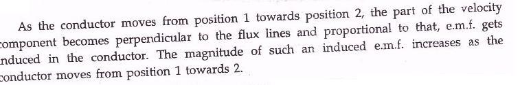
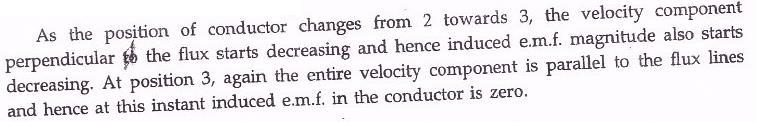
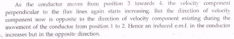
31 Working principle of an Alternator
32
Single Phase Induction Motors
 Single Phase Induction Motors Prof. T. H. Panchal Asst. Professor Department of Electrical Engineering Institute of Technology Nirma University, Ahmedabad Introduction As the name suggests, these motors
Electrical Machines -II
 Objective Type Questions: 1. Basically induction machine was invented by (a) Thomas Alva Edison (b) Fleming (c) Nikola Tesla (d) Michel Faraday Electrical Machines -II 2. What will be the amplitude and
DEPARTMENT OF ELECTRICAL AND ELECTRONICS ENGINEERING
 DEPARTMENT OF ELECTRICAL AND ELECTRONICS ENGINEERING QUESTION BANK 16EET41 SYNCHRONOUS AND INDUCTION MACHINES UNIT I SYNCHRONOUS GENERATOR 1. Why the stator core is laminated? 2. Define voltage regulation
EEE3441 Electrical Machines Department of Electrical Engineering. Lecture. Introduction to Electrical Machines
 Department of Electrical Engineering Lecture Introduction to Electrical Machines 1 In this Lecture Induction motors and synchronous machines are introduced Production of rotating magnetic field Three-phase
Part- A Objective Questions (10X1=10 Marks)
") Dr. Mahalingam College of Engineering and Technology, Pollachi-3 (An Autonomous Institution) CCET 3(2016Regulation) Name of Programme: B.E. (EEE) Course Code&Course Title: 16EET41 & Synchronous & Induction
Dr. Mahalingam College of Engineering and Technology, Pollachi-3 (An Autonomous Institution) CCET 3(2016Regulation) Name of Programme: B.E. (EEE) Course Code&Course Title: 16EET41 & Synchronous & Induction
10. Starting Method for Induction Motors
 10. Starting Method for Induction Motors A 3-phase induction motor is theoretically self starting. The stator of an induction motor consists of 3-phase windings, which when connected to a 3-phase supply
Stator rheostat, Autotransformer Star to Delta starter and rotor resistance starter.
 UNIT-IV 1.What are the types of starters? Stator rheostat, Autotransformer Star to Delta starter and rotor resistance starter. 2. List out the methods of speed control of cage type 3-phase induction motor?
Electrical Machines-I (EE-241) For S.E (EE)
 For S.E (EE)") PRACTICAL WORK BOOK For Academic Session 2013 Electrical Machines-I (EE-241) For S.E (EE) Name: Roll Number: Class: Batch: Department : Semester/Term: NED University of Engineer ing & Technology Electrical
PRACTICAL WORK BOOK For Academic Session 2013 Electrical Machines-I (EE-241) For S.E (EE) Name: Roll Number: Class: Batch: Department : Semester/Term: NED University of Engineer ing & Technology Electrical
2. Draw the speed-torque characteristics of dc shunt motor and series motor. (May2013) (May 2014)
 (May 2014)") UNIT 2 - DRIVE MOTOR CHARACTERISTICS PART A 1. What is meant by mechanical characteristics? A curve is drawn between speed-torque. This characteristic is called mechanical characteristics. 2. Draw the
UNIT 2 - DRIVE MOTOR CHARACTERISTICS PART A 1. What is meant by mechanical characteristics? A curve is drawn between speed-torque. This characteristic is called mechanical characteristics. 2. Draw the
Principles of Electrical Engineering
 D.C GENERATORS Principle of operation of D.C machines, types of D.C Generators, e.m.f equation of D.C Generator, O.C.C of a D.C Shunt Generator, Load characteristics of D.C.Generators GENERATOR PRINCIPLE:
INDUCTION MOTOR. There is no physical electrical connection to the secondary winding, its current is induced
 INDUCTION MOTOR INTRODUCTION An induction motor is an alternating current motor in which the primary winding on one member (usually the stator) is connected to the power source and a secondary winding
2014 ELECTRICAL TECHNOLOGY
 SET - 1 II B. Tech I Semester Regular Examinations, March 2014 ELECTRICAL TECHNOLOGY (Com. to ECE, EIE, BME) Time: 3 hours Max. Marks: 75 Answer any FIVE Questions All Questions carry Equal Marks ~~~~~~~~~~~~~~~~~~~~~~~~~~
Institute of Technology, Nirma University B. Tech. Sem. V: Electrical Engineering 2EE305: ELECTRICAL MACHINES II. Handout: AC Commutator Motors
 Institute of Technology, Nirma University B. Tech. Sem. V: Electrical Engineering 2EE305: ELECTRICAL MACHINES II Handout: AC Commutator Motors Prepared by: Prof. T. H. Panchal Learning Objective: Introduction
EE6351 ELECTRIC DRIVES AND CONTROL UNIT-1 INTRODUTION
 EE6351 ELECTRIC DRIVES AND CONTROL UNIT-1 INTRODUTION 1. What is meant by drive and electric drive? Machines employed for motion control are called drives and may employ any one of the prime movers for
ESO 210 Introduction to Electrical Engineering
 ESO 210 Introduction to Electrical Engineering Lectures-37 Polyphase (3-phase) Induction Motor 2 Determination of Induction Machine Parameters Three tests are needed to determine the parameters in an induction
UNIT 2. INTRODUCTION TO DC GENERATOR (Part 1) OBJECTIVES. General Objective
 OBJECTIVES. General Objective") DC GENERATOR (Part 1) E2063/ Unit 2/ 1 UNIT 2 INTRODUCTION TO DC GENERATOR (Part 1) OBJECTIVES General Objective : To apply the basic principle of DC generator, construction principle and types of DC generator.
DC GENERATOR (Part 1) E2063/ Unit 2/ 1 UNIT 2 INTRODUCTION TO DC GENERATOR (Part 1) OBJECTIVES General Objective : To apply the basic principle of DC generator, construction principle and types of DC generator.
DEPARTMENT OF EI ELECTRICAL MACHINE ASSIGNMENT 1
 It is the mark of an educated mind to be able to entertain a thought without accepting it. DEPARTMENT OF EI ELECTRICAL MACHINE ASSIGNMENT 1 1. Explain the Basic concepts of rotating machine. 2. With help
14 Single- Phase A.C. Motors I
 Lectures 14-15, Page 1 14 Single- Phase A.C. Motors I There exists a very large market for single-phase, fractional horsepower motors (up to about 1 kw) particularly for domestic use. Like many large volume
Electrical Machines II. Week 5-6: Induction Motor Construction, theory of operation, rotating magnetic field and equivalent circuit
 Electrical Machines II Week 5-6: Induction Motor Construction, theory of operation, rotating magnetic field and equivalent circuit Asynchronous (Induction) Motor: industrial construction Two types of induction
INTRODUCTION Principle
 DC Generators INTRODUCTION A generator is a machine that converts mechanical energy into electrical energy by using the principle of magnetic induction. Principle Whenever a conductor is moved within a
Unit III-Three Phase Induction Motor:
 INTRODUCTION Unit III-Three Phase Induction Motor: The three phase induction motor runs on three phase AC supply. It is an ac motor. The power is transferred by means of induction. So it is also called
Regulation: R16 Course & Branch: B.Tech EEE
 SIDDHARTH GROUP OF INSTITUTIONS :: PUTTUR Siddharth Nagar, Narayanavanam Road 517583 QUESTION BANK (Descriptive) Subject with Code : Electrical Machines-II (16EE215) Regulation: R16 Course & Branch: B.Tech
Single Phase Induction Motor. Dr. Sanjay Jain Department Of EE/EX
 Single Phase Induction Motor Dr. Sanjay Jain Department Of EE/EX Application :- The single-phase induction machine is the most frequently used motor for refrigerators, washing machines, clocks, drills,
Lecture 20: Stator Control - Stator Voltage and Frequency Control
 Lecture 20: Stator Control - Stator Voltage and Frequency Control Speed Control from Stator Side 1. V / f control or frequency control - Whenever three phase supply is given to three phase induction motor
Dev Bhoomi Institute Of Technology LABORATORY Department of Electrical And Electronics Engg. Electro-mechanical Energy Conversion II
 REV. NO. : REV. DATE : PAGE: 1 Electro-mechanical Energy Conversion II 1. To perform no load and blocked rotor tests on a three phase squirrel cage induction motor and determine equivalent circuit. 2.
The Wound-Rotor Induction Motor Part I
 Experiment 1 The Wound-Rotor Induction Motor Part I OBJECTIVE To examine the construction of the three-phase wound-rotor induction motor. To understand exciting current, synchronous speed and slip in a
ELECTRICAL MAINTENANCE
 ELECTRICAL MAINTENANCE II PRACTICAL JOURNAL DATA 1 EXPERIMENT NO. 1 AIM: TO FIND VOLTAGE RATIO OF A GIVEN TRANSFORMER. CIRCUIT DIAGRAM: OBSERVATION TABLE: Sr.No. 1 2 3 4 Primary Voltage (V 1 ) Secondary
CHAPTER THREE DC MOTOR OVERVIEW AND MATHEMATICAL MODEL
 CHAPTER THREE DC MOTOR OVERVIEW AND MATHEMATICAL MODEL 3.1 Introduction Almost every mechanical movement that we see around us is accomplished by an electric motor. Electric machines are a means of converting
Induction machine characteristics and operation. Induction Machines
 Induction Machines 1.1 Introduction: An essential feature of the operation of the synchronous machine is that the rotor runs at the same speed as the rotating magnetic field produced by the stator winding.
(d) None of the above.
 None of the above.") Dr. Mahalingam College of Engineering and Technology, Pollachi-3 (An Autonomous Institution affiliated to Anna niversity) CCET II (2016 Regulation) Name of Programme: B.E. (EEE) Course Code & Course Title:
Dr. Mahalingam College of Engineering and Technology, Pollachi-3 (An Autonomous Institution affiliated to Anna niversity) CCET II (2016 Regulation) Name of Programme: B.E. (EEE) Course Code & Course Title:
Unit-II Synchronous Motor
 Unit-II Synchronous Motor CONSTRUCTION OF THREE PHASE SYNCHRONOUS MOTOR PRINCIPLE OF OPERATION Prepared By P.Priyadharshini Ap/EEE - 1 - Note: 1. The average torque exerted on the rotor of synchronous
SIDDHARTH GROUP OF INSTITUTIONS :: PUTTUR
 SIDDHARTH GROUP OF INSTITUTIONS :: PUTTUR Siddharth Nagar, Narayanavanam Road 517583 QUESTION BANK (DESCRIPTIVE) Subject with Code : ET(16EE212) Year & Sem: II-B.Tech & II-Sem UNIT I DC GENERATORS Course
FATIMA MICHAEL COLLEGE OF ENGINEERING & TECHNOLOGY Senkottai Village, Madurai Sivagangai Main Road, Madurai
 Department of Mechanical Engineering QUESTION BANK SUBJECT NAME: ELECTRICAL DRIVES AND CONTROL YEAR / SEM: II / III UNIT I INTRODUCTION PART-A (2 MARKS) 1. Define Drives 2. Define Electric Drives. 3. What
2 Principles of d.c. machines
 2 Principles of d.c. machines D.C. machines are the electro mechanical energy converters which work from a d.c. source and generate mechanical power or convert mechanical power into a d.c. power. These
ST. ANNE S COLLEGE OF ENGINEERING AND TECHNOLOGY 9001:2015 CERTIFIED INSTITUTION) ANGUCHETTYPALAYAM, PANRUTI
 ANGUCHETTYPALAYAM, PANRUTI") ST. ANNE S COLLEGE OF ENGINEERING AND TECHNOLOGY (AN ISO 9001:2015 CERTIFIED INSTITUTION) ANGUCHETTYPALAYAM, PANRUTI 607 110. EE6504 ELECTRICAL MACHINES - II UNIT I SYNCHRONOUS GENERATOR PART A 1. What
ST. ANNE S COLLEGE OF ENGINEERING AND TECHNOLOGY (AN ISO 9001:2015 CERTIFIED INSTITUTION) ANGUCHETTYPALAYAM, PANRUTI 607 110. EE6504 ELECTRICAL MACHINES - II UNIT I SYNCHRONOUS GENERATOR PART A 1. What
Unit-IV. 1. Explain the operation, characteristics and application of DC and AC servo motor.
 Unit-IV Special Machines - Servo motor DC and AC servomotors; stepper motors variable reluctance and permanent magnet stepper motors; single phase synchronous motor reluctance motor and hysteresis motor
 VALLIAMMAI ENGINEERING COLLEGE MECHANICAL ENGINEERING ANNA UNIVERSITY CHENNAI II YEAR MECH / III SEMESTER EE6351 - ELECTRICAL DRIVES AND CONTROL (REGULATION 2013) UNIT I INTRODUCTION PART-A (2 MARKS) 1.
VALLIAMMAI ENGINEERING COLLEGE
 VALLIAMMAI ENGINEERING COLLEGE SRM Nagar, Kattankulathur 603 203. DEPARTMENT OF ELECTRICAL AND ELECTRONICS ENGINEERING Question Bank EE6401 ELECTRICAL MACHINES I UNIT I: MAGNETIC CIRCUITS AND MAGNETIC
 EE6401 ELECTRICAL MACHINES I UNIT I: MAGNETIC CIRCUITS AND MAGNETIC MATERIALS PART: A 1. Define EMF and MMF. 2. Name the main magnetic quantities with their symbols having the following units: Webers,
 APGENCO/APTRANSCO Assistant Engineer Electrical Previous Question Papers Q.1 The two windings of a transformer is conductively linked. inductively linked. not linked at all. electrically linked. Q.2 A
VIII. Three-phase Induction Machines (Asynchronous Machines) Induction Machines
 Induction Machines") VIII. Three-phase Induction Machines (Asynchronous Machines) Induction Machines 1 Introduction Three-phase induction motors are the most common and frequently encountered machines in industry simple design,
VIII. Three-phase Induction Machines (Asynchronous Machines) Induction Machines 1 Introduction Three-phase induction motors are the most common and frequently encountered machines in industry simple design,
SSC-JE STAFF SELECTION COMMISSION ELECTRICAL ENGINEERING STUDY MATERIAL ELECTRICAL MACHINES
 1 SSC-JE STAFF SELECTION COMMISSION ELECTRICAL ENGINEERING STUDY MATERIAL 28-B/7, Jia Sarai, Near IIT, Hauz Khas, New Delhi-110016. Ph. 011-26514888. www.engineersinstitute.com 2 CONTENT 1. : DC MACHINE,
DC CIRCUITS ELECTROMAGNETISM
 DC CIRCUITS 1. State and Explain Ohm s Law. Write in brief about the limitations of Ohm s Law. 2. State and explain Kirchhoff s laws. 3. Write in brief about disadvantages of series circuit and advantages
Sub:EE6604/DESIGN OF ELECTRICAL MACHINES Unit V SYNCHRONOUS MACHINES. 2. What are the two type of poles used in salient pole machines?
 SRI VIDYA COLLEGE OF ENGINEERING & TECHNOLOGY DEPARTMENT OF EEEE QUESTION BANK Sub:EE6604/DESIGN OF ELECTRICAL MACHINES Unit V SYNCHRONOUS MACHINES 1. Name the two types of synchronous machines. 1. Salient
St.MARTIN S ENGINEERING COLLEGE Dhulapally, Secunderabad
 St.MARTIN S ENGINEERING COLLEGE Dhulapally, Secunderabad-500 014 Subject: STATIC DRIVES Class : EEE III TUTORIAL QUESTION BANK Group I QUESTION BANK ON SHORT ANSWER QUESTION UNIT-I 1 What is meant by electrical
Pretest Module 21 Unit 4 Single-Phase Motors
 Pretest Module 21 Unit 4 Single-Phase Motors 1. What are the four main components of a single-phase motor? Rotor, stator, centrifugal switch, end bells and bearings 2. How is a rotating field created in
Pretest Module 21 Units 1-4 AC Generators & Three-Phase Motors
 Pretest Module 21 Units 1-4 AC Generators & Three-Phase Motors 1. What are the two main parts of a three-phase motor? Stator and Rotor 2. Which part of a three-phase squirrel-cage induction motor is a
SHRI ANGALAMMAN COLLEGE OF ENGINEERING AND TECHNOLOGY (An ISO 9001:2008 Certified Institution) SIRUGANOOR, TIRUCHIRAPPALLI
 SIRUGANOOR, TIRUCHIRAPPALLI") SHRI ANGALAMMAN COLLEGE OF ENGINEERING AND TECHNOLOGY (An ISO 9001:2008 Certified Institution) SIRUGANOOR, TIRUCHIRAPPALLI 621 105 DEPARTMENT OF ELECTRICAL AND ELECTRONICS ENGINEERING EE1205 - ELECTRICAL
SHRI ANGALAMMAN COLLEGE OF ENGINEERING AND TECHNOLOGY (An ISO 9001:2008 Certified Institution) SIRUGANOOR, TIRUCHIRAPPALLI 621 105 DEPARTMENT OF ELECTRICAL AND ELECTRONICS ENGINEERING EE1205 - ELECTRICAL
QUESTION BANK SPECIAL ELECTRICAL MACHINES
 SEVENTH SEMESTER EEE QUESTION BANK SPECIAL ELECTRICAL MACHINES TWO MARK QUESTIONS 1. What is a synchronous reluctance 2. What are the types of rotor in synchronous reluctance 3. Mention some applications
2-marks question bank UNIT I - TRANSFORMERS UNIT II: AC MACHINES
 2-marks question bank UNIT I - TRANSFORMERS 1. What is all day efficiency? 2. What are the applications of auto transformers? 3. Why transformer rating is expressed in KVA? 4. Does transformer draw any
COLLEGE OF ENGINEERING DEPARTMENT OF ELECTRICAL AND ELECTRONICS ENGINEERING QUESTION BANK SUBJECT CODE & NAME : EE 1001 SPECIAL ELECTRICAL MACHINES
 KINGS COLLEGE OF ENGINEERING DEPARTMENT OF ELECTRICAL AND ELECTRONICS ENGINEERING QUESTION BANK SUBJECT CODE & NAME : EE 1001 SPECIAL ELECTRICAL MACHINES YEAR / SEM : IV / VII UNIT I SYNCHRONOUS RELUCTANCE
PHY 152 (ELECTRICITY AND MAGNETISM)
") PHY 152 (ELECTRICITY AND MAGNETISM) ELECTRIC MOTORS (AC & DC) ELECTRIC GENERATORS (AC & DC) AIMS Students should be able to Describe the principle of magnetic induction as it applies to DC and AC generators.
PHY 152 (ELECTRICITY AND MAGNETISM) ELECTRIC MOTORS (AC & DC) ELECTRIC GENERATORS (AC & DC) AIMS Students should be able to Describe the principle of magnetic induction as it applies to DC and AC generators.
AE105 PRINCIPLES OF ELECTRICAL ENGINEERING JUNE 2014
 Q.2 a. Explain in detail eddy current losses in a magnetic material. Explain the factors on which it depends. How it can be reduced? IETE 1 b. A magnetic circuit with a single air gap is shown in given
A Practical Guide to Free Energy Devices
 A Practical Guide to Free Energy Devices Part PatD20: Last updated: 26th September 2006 Author: Patrick J. Kelly This patent covers a device which is claimed to have a greater output power than the input
II/IV B.Tech(Regular) DEGREE EXAMINATION. Electronics & Instrumentation Engineering
 DEGREE EXAMINATION. Electronics & Instrumentation Engineering") SCHME OF EVALUTION II/IV B.Tech(Regular) DEGREE EXAMINATION JUNE,2016 EI ET 403 Electrical Technology Electronics & Instrumentation Engineering Max.Marks :60 marks -----------------------------------------------------------------------------------------------------------
SCHME OF EVALUTION II/IV B.Tech(Regular) DEGREE EXAMINATION JUNE,2016 EI ET 403 Electrical Technology Electronics & Instrumentation Engineering Max.Marks :60 marks -----------------------------------------------------------------------------------------------------------
EE6401 ELECTRICAL MACHINES I UNIT I: MAGNETIC CIRCUITS AND MAGNETIC MATERIALS PART: A 1. Define EMF and MMF. 2. Name the main magnetic quantities
 EE6401 ELECTRICAL MACHINES I UNIT I: MAGNETIC CIRCUITS AND MAGNETIC MATERIALS PART: A 1. Define EMF and MMF. 2. Name the main magnetic quantities with their symbols having the following units: Webers,
ECE 325 Electric Energy System Components 6 Three Phase Induction Motors. Instructor: Kai Sun Fall 2016
 ECE 325 Electric Energy System Components 6 Three Phase Induction Motors Instructor: Kai Sun Fall 2016 1 Content (Materials are from Chapters 13-15) Components and basic principles Selection and application
Page 1. Design meeting 18/03/2008. By Mohamed KOUJILI
 Page 1 Design meeting 18/03/2008 By Mohamed KOUJILI I. INTRODUCTION II. III. IV. CONSTRUCTION AND OPERATING PRINCIPLE 1. Stator 2. Rotor 3. Hall sensor 4. Theory of operation TORQUE/SPEED CHARACTERISTICS
UNIT-1 Drive Characteristics
 UNIT-1 Drive Characteristics DEFINITION: Systems employed for motion control are called as DRIVES Drives may employ any of the prime movers such as diesel or petrol engine, gas or steam turbines, steam
To study the constructional features of ammeter, voltmeter, wattmeter and energymeter.
 Experiment o. 1 AME OF THE EXPERIMET To study the constructional features of ammeter, voltmeter, wattmeter and energymeter. OBJECTIVE 1. To be conversant with the constructional detail and working of common
Electrical Theory. Generator Theory. PJM State & Member Training Dept. PJM /22/2018
 Electrical Theory Generator Theory PJM State & Member Training Dept. PJM 2018 Objectives The student will be able to: Describe the process of electromagnetic induction Identify the major components of
GROUP OF INSTITUTIONS :: PUTTUR UNIT I SINGLE PHASE TRANSFORMERS
 SIDDHARTH GROUP OF INSTITUTIONS :: PUTTUR Siddharth Nagar, Narayanavanam Road 517583 QUESTION BANK (Descriptive) Subject with Code : Electrical Machines-II (16EE215) Course & Branch: B.Tech EEE Regulation:
Synchronous Motor Drives
 UNIT V SYNCHRONOUS MOTOR DRIVES 5.1 Introduction Synchronous motor is an AC motor which rotates at synchronous speed at all loads. Construction of the stator of synchronous motor is similar to the stator
Synchronous Generators I. Spring 2013
 Synchronous Generators I Spring 2013 Construction of synchronous machines In a synchronous generator, a DC current is applied to the rotor winding producing a rotor magnetic field. The rotor is then turned
DHANALAKSHMI COLLEGE OF ENGINEERING MANIMANGALAM. TAMBARAM, CHENNAI B.E. ELECTRICAL AND ELECTRONICS ENGINEERING
 DHANALAKSHMI COLLEGE OF ENGINEERING MANIMANGALAM. TAMBARAM, CHENNAI B.E. ELECTRICAL AND ELECTRONICS ENGINEERING V SEMESTER EE2305 ELECTRICAL MACHINES II LABORATORY LABORATORY MANUAL 1 CONTENT S. No. Name
Most home and business appliances operate on single-phase AC power. For this reason, singlephase AC motors are in widespread use.
 Chapter 5 Most home and business appliances operate on single-phase AC power. For this reason, singlephase AC motors are in widespread use. A single-phase induction motor is larger in size, for the same
Date: Name: ID: LABORATORY EXPERIMENT NO. 8 INDUCTION MOTOR/GENERATOR 8-1
 Date: Name: ID: LABORATORY EXPERIMENT NO. 8 INDUCTION MOTOR/GENERATOR 8-1 OBJECT 1. To determine the general performance of a squirrel motors 2. To observe the characteristics of induction generators.
Single-Phase AC Induction Squirrel Cage Motors. Permanent Magnet Series Wound Shunt Wound Compound Wound Squirrel Cage. Induction.
 FAN ENGINEERING Information and Recommendations for the Engineer Twin City Fan FE-1100 Single-Phase AC Induction Squirrel Cage Motors Introduction It is with the electric motor where a method of converting
SYLLABUS 1. SYNCHRONOUS GENERATOR 9 2. SYNCHRONOUS MOTOR 8
 SYLLABUS 1. SYNCHRONOUS GENERATOR 9 Constructional details Types of rotors emf equation Synchronous reactance Armature reaction Voltage regulation EMF, MMF, ZPF and A.S.A methods Synchronizing and parallel
UNIT-I ALTERNATORS PART-A
 UNIT-I ALTERNATORS 1. What principle is used in Alternators? 2. What are the requirements of an alternator? 3. Mention the types of alternator rotor. 4. What is hunting in alternators? 5. What are the
BELT-DRIVEN ALTERNATORS
 CHAPTER 13 BELT-DRIVEN ALTERNATORS INTRODUCTION A generator is a machine that converts mechanical energy into electrical energy using the principle of magnetic induction. This principle is based on the
CHAPTER 6 INTRODUCTION TO MOTORS AND GENERATORS
 CHAPTER 6 INTRODUCTION TO MOTORS AND GENERATORS Objective Describe the necessary conditions for motor and generator operation. Calculate the force on a conductor carrying current in the presence of the
INSTITUTE OF AERONAUTICAL ENGINEERING Dundigal, Hyderabad
 INSTITUTE OF AERONAUTICAL ENGINEERING Dundigal, Hyderabad - 500 043 MECHANICAL ENGINEERING ASSIGNMENT Name : Electrical and Electronics Engineering Code : A40203 Class : II B. Tech I Semester Branch :
Fachpraktikum Elektrische Maschinen. Theory of Induction Machines
 Fachpraktikum Elektrische Maschinen Theory of Induction Machines Prepared by Arda Tüysüz January 2013 Fundamentals Induction machines (also known as asynchronous machines) are by far the most common type
MAGNETIC EFFECTS OF ELECTRIC CURRENT
 MAGNETIC EFFECTS OF ELECTRIC CURRENT It is observed that when a compass is brought near a current carrying conductor the needle of compass gets deflected because of flow of electricity. This shows that
Synchronous Generators I. EE 340 Spring 2011
 Synchronous Generators I EE 340 Spring 2011 Construction of synchronous machines In a synchronous generator, a DC current is applied to the rotor winding producing a rotor magnetic field. The rotor is
AC MOTOR TYPES. DESCRIBE how torque is produced in a single-phase AC motor. EXPLAIN why an AC synchronous motor does not have starting torque.
 Various types of AC motors are used for specific applications. By matching the type of motor to the appropriate application, increased equipment performance can be obtained. EO 1.5 EO 1.6 EO 1.7 EO 1.8
Question 2: Around the bar magnet draw its magnetic fields. Answer:
 Chapter 13: Magnetic Effects of Electric Current Question 1: What is the reason behind the compass needle is deflected when it is brought close to the bar magnet? Compass needles work as a small bar magnet;
Contents. Review of Electric Circuitd. Preface ;
 Preface ; Chapter 1 Review of Electric Circuitd 1.1 Introduction, 1 1.2 Direct Circuit Current, 1 1.2.1 Voltage, 3 1.2.2 Power, 3 1.2.3 Ohm's Law, 5 1.2.4 KirchhofTs Laws, 5 1.2.4.1 Kirchhoff s Current
AC Motors vs DC Motors. DC Motors. DC Motor Classification ... Prof. Dr. M. Zahurul Haq
 AC Motors vs DC Motors DC Motors Prof. Dr. M. Zahurul Haq http://teacher.buet.ac.bd/zahurul/ Department of Mechanical Engineering Bangladesh University of Engineering & Technology ME 6401: Advanced Mechatronics
Chapter 3.2: Electric Motors
 Part I: Objective type questions and answers Chapter 3.2: Electric Motors 1. The synchronous speed of a motor with 6 poles and operating at 50 Hz frequency is. a) 1500 b) 1000 c) 3000 d) 750 2. The efficiency
Short Term Course On Hydropower Development Engineering (Electrical) for Teachers of Polytechnics in Uttarakhand L33-2
 for Teachers of Polytechnics in Uttarakhand L33-2") Short Term Course On Hydropower Development Engineering (Electrical) for Teachers of Polytechnics in Uttarakhand ( July 14-18, 2007) Lecture on L33-2 By S.N.Singh Senior Scientific officer ALTERNATE HYDRO
Short Term Course On Hydropower Development Engineering (Electrical) for Teachers of Polytechnics in Uttarakhand ( July 14-18, 2007) Lecture on L33-2 By S.N.Singh Senior Scientific officer ALTERNATE HYDRO
R07 SET - 1
 R07 SET - 1 II B. Tech II Semester Supplementary Examinations April/May 2013 ELECTRICAL MACHINES - II (Electrical and Electronics Engineering) Time: 3 hours Max. Marks: 80 Answer any FIVE Questions All
Module 9. DC Machines. Version 2 EE IIT, Kharagpur
 Module 9 DC Machines Lesson 38 D.C Generators Contents 38 D.C Generators (Lesson-38) 4 38.1 Goals of the lesson.. 4 38.2 Generator types & characteristics.... 4 38.2.1 Characteristics of a separately excited
PI Electrical Equipment - Course PI 30.2 MOTORS
 Electrical Equipment - Course PI 30.2 MOTORS OBJECTIVES On completion of this module the student will be able to: 1. Briefly explain, in writing, "shaft rotation" as an interaction of stator and rotor
5. LINEAR MOTORS 5.1 INTRODUCTION
 5.1 INTRODUCTION 5. LINEAR MOTORS Linear Electric Motors belong to the group of Special electrical machines that convert electrical energy into mechanical energy of translator motion. Linear Electric motors
INSTITUTE OF AERONAUTICAL ENGINEERING (Autonomous) Dundigal, Hyderabad DEPARTMENT OF ELECTRICAL AND ELECTRONICS ENGINEERING
 Dundigal, Hyderabad DEPARTMENT OF ELECTRICAL AND ELECTRONICS ENGINEERING") Course Name Course Code Class Branch INSTITUTE OF AERONAUTICAL ENGINEERING (Autonomous) Dundigal, Hyderabad - 500 0 DEPARTMENT OF ELECTRICAL AND ELECTRONICS ENGINEERING : Static Drives : A60225 : III -
Course Name Course Code Class Branch INSTITUTE OF AERONAUTICAL ENGINEERING (Autonomous) Dundigal, Hyderabad - 500 0 DEPARTMENT OF ELECTRICAL AND ELECTRONICS ENGINEERING : Static Drives : A60225 : III -
Chapter 7: DC Motors and Transmissions. 7.1: Basic Definitions and Concepts
 Chapter 7: DC Motors and Transmissions Electric motors are one of the most common types of actuators found in robotics. Using them effectively will allow your robot to take action based on the direction
Basic Motor Theory. Introduction
 Basic Motor Theory Introduction It has been said that if the Ancient Romans, with their advanced civilization and knowledge of the sciences, had been able to develop a steam motor, the course of history
UNIT I SYNCHRONOUS GENERATOR PART-A
 1. What is an alternator? UNIT I SYNCHRONOUS GENERATOR PART-A An alternator or AC generator is a synchronous machine which converts mechanical energy into electrical energy and produces alternating emf.
Lab Electrical Power Engineering I
 INSTITUT FÜR ELEKTRISCHE MASCHINEN RHEINISCH-WESTFÄLISCHE TECHNISCHE HOCHSCHULE AACHEN Lab Electrical Power Engineering I Test 3: Induction machine with squirrel cage rotor and slip ring rotor 1 Experiment
ST.ANNE S COLLEGE OF ENGINEERING AND TECHNOLOGY ANGUCHETTYPALAYAM, PANRUTI
 ST.ANNE S COLLEGE OF ENGINEERING AND TECHNOLOGY ANGUCHETTYPALAYAM, PANRUTI 607106. QUESTION BANK DECEMBER 2017 - JUNE 2018 / EVEN SEMESTER BRANCH: EEE YR/SEM: II/IV BATCH: 2016-2020 SUB CODE/NAME: EE6401
Circuit Diagram For Speed Control Of Slip Ring Induction Motor
 Circuit Diagram For Speed Control Of Slip Ring Induction Motor A wound-rotor motor is a type of induction motor where the rotor windings are Compared to a squirrel-cage rotor, the rotor of the slip ring
G PULLAIAH COLLEGE OF ENGINEERING & TECHNOLOGY DEPARTMENT OF ELECTRICAL & ELECTRONICS ENGINEERING
 G PULLAIAH COLLEGE OF ENGINEERING & TECHNOLOGY DEPARTMENT OF ELECTRICAL & ELECTRONICS ENGINEERING ENERGY AUDITING AND DEMAND SIDE MANAGEMENT (15A02706) UNIT-2 ENERGY EFFICIENT MOTORS AND POWER FACTOR IMPROVEMENT
Electrical Machines I Week 1: Overview, Construction and EMF equation
 Electrical Machines I Week 1: Overview, Construction and EMF equation Course Contents Definition of the magnetic terms, magnetic materials and the B-H curve. Magnetic circuits principles. Electromechanical
DC MOTOR. Prashant Ambadekar
 DC MOTOR Prashant Ambadekar Electric Motor: The input is electrical energy (from the supply source), and the output is mechanical energy (to the load). Electric Generator: The Input is mechanical energy
Almost 200 years ago, Faraday looked for evidence that a magnetic field would induce an electric current with this apparatus:
 Chapter 21 Electromagnetic Induction and Faraday s Law Chapter 21 Induced EMF Faraday s Law of Induction; Lenz s Law EMF Induced in a Moving Conductor Changing Magnetic Flux Produces an E Field Inductance
SPH3U UNIVERSITY PHYSICS
 SPH3U UNIVERSITY PHYSICS ELECTRICITY & MAGNETISM L (P.599-604) The large-scale production of electrical energy that we have today is possible because of electromagnetic induction. The electric generator,
TWO MARK QUESTIONS-ANSWERS
 TWO MARK QUESTIONS-ANSWERS DEPARTMENT: MECH SEMESTER : III SUBJECT CODE: ME2205 SUBJECT NAME: ELECTRIC DRIVES & CONTROL 1. Define Drive and Electric Drive. Drive: A particular system employed for motion
Short questions and answers. EE1251 Electrical Machines II
 Short questions and answers EE1251 Electrical Machines II 1. Why almost all large size Synchronous machines are constructed with rotating field system type? The following are the principal advantages of