T5S4P3 Synchronous Condensers Application. Mr. Marco Schenone Mr. Sandro Tuscano Mr. Alessandro Oldrati
|
|
|
- Steven Riley
- 6 years ago
- Views:
Transcription


1 Mr. Marco Schenone Mr. Sandro Tuscano Mr. Alessandro Oldrati 1
, in cooperation with")
2 Introduction Ansaldo Energia has recently completed the manufacture, installation and commissioning of two synchronous condenser sets for Terna Rete Italia in the preexisting substation of Codrongianos (Sardinia - Italy), in cooperation with ABB. 2
3 Introduction The synchronous condensers are connected to the EHV/HV grid of Sardinia (part of the Italian national grid) to increase the network s short-circuit power and inertia. This is particularly important for a grid like the one in Sardinia, where conventional generation plants fired by fossil fuels have been supplemented by significant capacity from renewable sources (wind and photovoltaic in particular). In addition, the links between Sardinian, Italian and Corsican grids, which use High Voltage Direct Current (HVDC) submarine cables, create the need for a continuous local supply of variable reactive power. At the instance of Terna the synchronous condensers have been made able to be remotely controlled by Terna substation located in Rondissone (Piedmont north of Italy) during the normal operation. 3
4 The supplied system The supplied system consists of two synchronous condenser sets, each mainly made up of: 250 MVAr synchronous condenser (SC) and relevant auxiliary systems 330 MVA step-up transformer for connection to EHV grid MV circuit breaker between SC and step-up transformer unit and auxiliary transformers MV and LV distribution panels protection, command, control and monitoring systems. These sets are not completely independent, because they have some common equipment, like the control system and the closed circuit cooling water system. 4

5 The synchronous condensers The two synchronous condensers are based on well proven standardized 2-pole air cooled turbogenerator design WY23Z-109RR, normally coupled to gas turbine in power plants, with some adjustments, which involve its auxiliary systems as well, introduced to satisfy the special operating conditions. 5
 and rotor opposite")
6 The synchronous condensers The main characteristics of this type of generator in standard version are: cylindrical rotor with 2 poles closed circuit cooling with 4 air-to-water coolers incorporated into the housing self-ventilating air cooling system for stator and rotor slip ring housing for static excitation class F insulation system for stator (resin rich technology) and rotor opposite collector end shaft grounding device and collector end bearing double insulation. 6
7 The synchronous condensers Main data Unit Value Rated power MVAr 250 Rated power factor - 0 over-excited Max. reactive power in under-excitation at rated voltage MVAr 125 Rated current / voltage A / kv 7597 / 19 Voltage variation range (continuous; exceptional) (*) % ± 5; ± 8 Rated frequency / speed Hz / rpm 50 / 3000 Frequency variation range (continuous; exceptional) (*) % ±2; -5 / +3 Max combined V/f variation (continuous; exceptional) (*) p.u. 1.05; 1.08 Phase number / Phase connection - 3/STAR Excitation current / voltage (at 110 C) at rated load A / V 1557 / 376 Cooling water / primary coolant rated temperature C 35 / 40 Ambient temperature range C / m a.s.l Site altitude m a.s.l. 315 Short circuit ratio Inertia moment (J) kg m (*) refer to figure on page 9 7
8 The synchronous condensers Voltage/frequency operation range 8

9 The synchronous condensers Peculiarities and auxiliary systems Some peculiarities, related to the lack of coupling to any turbine, has been added for the synchronous condensers with respect to the standard design: collector end thrust bearing phonic wheel, speed sensors and keyphasor on collector end of rotor. Moreover, the following main auxiliary systems, derived from the experience on gas turbines, have been adapted in size and characteristics in order to satisfy the project conditions: closed circuit cooling water system ventilation system lubrication/jacking oil system excitation system static frequency converters (SFCs). 9

10 The synchronous condensers Closed circuit cooling water system 10

11 The synchronous condensers Ventilation system 11

12 The synchronous condensers Lubrication/jacking oil system 12
13 Control philosophy The plant of synchronous condensers (ICS) is managed by a distributed control system (SC-ICS) which allows command, control and supervision of all equipment, power components and auxiliary systems. The command of these components is possible from three different levels: level 1 Local Peripheral : MV / LV local boards and control panels; level 2 Local Centralized : stations of SC-ICS with human-machine interface (HMI) in the local control room of synchronous condensers and in the control room of SA.Co.I. (Sardinia-Corsica-Italy) HVDC-LCC link, located in Codrongianos substation. level 3 Remote : remote control stations of SCCT (Terna Control and Conduction System) with HMI, located in Rondissone substation. These three levels are mutually exclusive, because the permission to command given to a specific level inhibits other levels from operating. 13
14 Control philosophy The normal operation is managed at level 3 Remote, in which the availability of macro-commands and main information on the plant conditions is exclusively present, in order to simplify the work of operators and face adequately the constraints of exchanging data between SCCT in Rondissone and SC-ICS in Codrongianos via IEC protocol. The local SC-ICS permits the management of all operative conditions at levels 2 and 3, included the start-up and the stop of a single unit or both of them. Since the plant is functionally divided in different systems and subsystems, for all of them a start-up sequence and a stop sequence have been arranged; moreover each system is managed by automatic logics during normal operation and in case of malfunctions. In order to simplify the management of units on the part of operators both from level 2 and 3, a main start-up sequence and a main stop sequence of the single unit have been arranged: these main sequences activate progressively the sequences of single systems to perform all possible transitions among the different states of the condensers. 14
15 Control philosophy From STILL to READY From READY to CONNECTED STILL UNIT READY UNIT CONNECTED UNIT From READY to STILL From CONNECTED to READY Still unit : the synchronous condenser (SC) is still and disconnected from the grid, its dedicated auxiliary systems are still, the auxiliary systems in common with the other unit can be in operation. Ready unit : the SC is disconnected from the grid, its dedicated auxiliary systems and the auxiliary systems in common with the other unit are in operation. This is the condition of operational rest in which the condenser is maintained in order to be put into service quickly and reliably. Connected unit : the synchronous condenser is connected to the grid. 15
16 Malfunctions In case of malfunctions, the logics in the SC-ICS automatically disconnect the unit from the grid in the following ways, depending on the type of protection activated: mechanical trip : disconnection from the grid and consequent electrical braking by means of SFC up to the complete stop of the unit; electrical trip (electrical problem inside the condenser): disconnection from the grid and consequent natural inertial slowing down to the complete stop of the unit; electrical disconnection (electrical problem outside the condenser): disconnection from the grid and consequent electrical braking by means of SFC up to the turning gear speed. 16
 is used to accelerate (or")

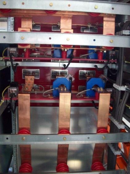
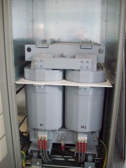
17 Starting system A Static Frequency Converter (SFC) is used to accelerate (or brake) the condenser, by driving the rotating machine as a synchronous motor kva 2250 kw 17

18 Starting data By turning on the thyristors at the right time, the inverter is able to anticipate (or delay) the stator magnetic field and to accelerate (or brake) the rotor, that in the meantime must be supplied by the excitation system. The SFC controls the excitation system by a field current reference signal and regulates the stator voltage at 1500 V, after an initial ramp. The SFC is able to start the condenser from zero speed or to grab the condenser at higher speed, also next to the rated speed of 3000 rpm. The SFC size of 2250 kw allows to reach the final speed value within 7 minutes, starting from zero speed. 18

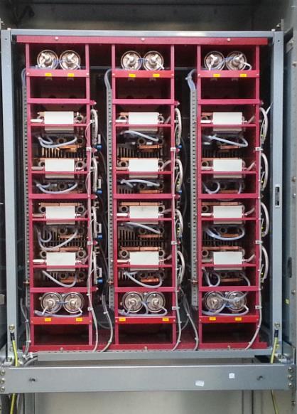


19 Main SFC circuit 19
20 Overspeed The control of the static starter has a speed regulator, that brings the condenser frequency over the actual grid frequency, to allow the synchrocheck to close the main circuit breaker during the natural speed fall down. The maximum speed reached by the SFC must allow to synchronize the unit at the higher grid frequency of 51,5 Hz (1.03 p.u.), that is an exceptional condition foreseen less than 10 times per year: in this case the maximum peak speed of the condenser can arrive at about 53 Hz. In order to avoid stressing the condenser rotor with unnecessary overspeed at each starting, the final SFC frequency is not a fixed value, but it is calculated each time on the base of the actual grid frequency. 20

21 Synchronization At the maximum speed the SFC is switched off, while the excitation system takes the lead and performs a ramp to increase the condenser voltage from 1500 V to the actual value of the grid voltage: this ramp takes about 4 seconds. In the meanwhile the speed is passively slowing down. When the speed and the voltage fulfill the synchronizing criteria, the main circuit breaker closing command is given. Legend: Violet trace = stator voltage Green trace = frequency Yellow trace = active power max ΔV 2% max Δf 1 % max Δ angle 40 deg 21
22 Consecutive starting attempts Since the condenser is not equipped with a flywheel for additional inertia (that would give additional time during the slowing down), the time available to align the vector of the condenser voltage to the grid after the voltage ramp is quite short (about 8 seconds), so during this time there are only one or two chances to get the synchronizing conditions. For this reason, in case of failed parallel the automatic sequence will try immediately another attempt, by activating again the static starter when the condenser speed has dropped to about 2900 rpm. After the third consecutive starting attempt, the SFC is switched off and the speed goes down naturally to 0 rpm, without electrical braking; further starting commands are up to the operator. The statistics observed during the commissioning and first operation show that the chance to fail the parallel at the first attempt is very unlikely. 22

23 Electrical braking Green = speed Grey = stator voltage Black = SFC DC current Red = excitation current The absence of a mechanical brake leads the condenser to slow down in about half an hour, by only mechanical friction. For this reason, the electrical braking is normally carried out in the automatic shutdown sequences by means of the SFC, with energy recovery to the grid. In this way the condenser can be stopped in about 4 minutes. 23
, by a set of disconnecting switches and the relevant logics. This solution guarantees a 100% redundancy.")
24 Crossed starting Unlike the excitation system, the SFC internal components are not redundant, but the complete starting system of each unit can also start the other condenser (crossed starting), by a set of disconnecting switches and the relevant logics. This solution guarantees a 100% redundancy. 24

25 Turning gear function As the condenser is not equipped with a mechanical turning gear, the static starter takes care of this duty. To avoid bending of the rotor, especially during the cooling phase after shut down, suitable cycles of periodical turning are accomplished by the logics of the control system and the static starter. For example, a typical cycle is 2 hours of rotation at 120 rpm every 12 hours. In case of starting after a long maintenance stop without periodical turning, at least 20 minutes rotation is requested before starting the synchronization sequence, to avoid anomalous vibrations during ramp up. 25
26 SFC tasks - Priority policy The following tasks can be requested to each SFC: Start condenser 1 Start condenser 2 Brake condenser 1 Brake condenser 2 Turning gear for condenser 1 Turning gear for condenser 2 Simultaneous operations of the 2 SFCs are allowed, until no crossed operation is involved. To handle all possible situation of simultaneous requests, the following priority order is assigned (from the highest to the lowest priority): 1) Braking command for mechanical trip 2) Starting command 3) Braking command, except in the case of mechanical trip 4) Turning gear function If the same operation is requested simultaneously to the same SFC for the two condensers, the priority is given to the command that first comes. 26
27 Condenser operative modes The synchronous condenser connected to the grid can operate in the following modes, that can be chosen by the operator at level 2 and 3, acting on the AVR (Automatic Voltage Regulator) of the excitation system: Control of the stator voltage Control of the reactive power Control by ASRV (Automatic System for Regulating Voltage). In the first two operative modes the voltage at the stator terminals of the SC or the reactive power exchanged by the SC are maintained constant by the AVR, that receives UP and DOWN commands from the SC-ICS to change the setpoint reference. In the ASRV mode, which is the default regulation, the AVR adjusts the voltage at the stator terminals on the basis of the reactive power reference coming from the System Operator. Alternatively the ASRV can regulate the voltage at the HV busbar. The ASRV (included in the SC-ICS) also balances the reactive power between the two condensers. 27
28 Conclusion On completion of testing, the first condenser was connected to the grid on September 28, 2014, bringing this event forward 4 months with respect to the initial scheduled date: this result was obtained also thanks to the choice of using a standardized turbogenerator as condenser. The second condenser was connected to the grid on December 4, During the commissioning and the first months of operation the 2 condensers were controlled from level 2 by Ansaldo Energia and ABB personnel, with a gradual handover to the level 3 in charge of Terna personnel. Nowadays the plant is in full operation controlled at level 3 and the condensers are actively supporting the local network. An event occurred on November 11th 2014 is worth to be mentioned: due to a grid fault, 70% of the Sardinian power production was lost in about 1 minute and SC1 operated at its maximum reactive power in under-excitation, avoiding the complete black-out in the island. 28
29 Thanks for Your attention 29
GE Energy. Variable Frequency Transformers Grid Inter-tie
 GE Energy Variable Frequency Transformers Grid Inter-tie Variable Frequency Transformers GE Energy revolutionizes the world of transmission solutions with its new Variable Frequency Transformer (VFT).
Dead bus synchronizing. Applications
 Dead bus synchronizing White paper TN004 Author: Florian Blazak Head of special projects Engineering department The synchronization of generators in a powerplant can be done by two different ways: - The
Standby Power Systems
 Source: Power Quality in Electrical Systems Chapter 13 Standby Power Systems The term standby power systems describes the equipment interposed between the utility power source and the electrical load to
Modular Standardized Electrical and Control Solutions for Fast Track Projects
 Modular Standardized Electrical and Control Solutions for Supporting fast track projects ABB is the leading supplier of electrical and control equipment for power plants. The company offers a comprehensive
Document Code: 1 (8) Issuing date: Status:
 Issuing date: Status:") Document Code: 1 (8) Project : MULTI FUEL CFB BOILER SIMULATOR Author: Approved: Employer: JJA Document title: SYSTEM DESCRIPTION TURBINE CONTROL Submitted for: Employer reference: Other information: Document
Document Code: 1 (8) Project : MULTI FUEL CFB BOILER SIMULATOR Author: Approved: Employer: JJA Document title: SYSTEM DESCRIPTION TURBINE CONTROL Submitted for: Employer reference: Other information: Document
ABB Wind Power Solution
 Feng Li, Wind ISI, CNABB, November, 2016 ABB Wind Power Solution November 13, 2016 Slide 1 ABB deliveries from A to Z into the wind industry Wind power generation, transmission and integration, control
SINAMICS SM150. 4/2 Overview. 4/2 Benefits. 4/2 Design. 4/6 Function. 4/8 Selection and ordering data. 4/8 Options
 /2 Overview /2 Benefits /2 Design /6 Function /8 Selection and ordering data /8 Options Technical data /1 General technical data /15 Control properties /15 Ambient conditions /16 Installation conditions
BRUSHLESS EXCITERS FOR TURBINE GENERATORS
 BRUSHLESS EXCITERS FOR TURBINE GENERATORS Economical, Manpower Saving Exciters Based on State-of-the-Art Technology. Mitsubishi Electrical manufactures brushless exciters for all types of turbine generator,
Unit Protection System for Pumped-Storage Power Stations
 Unit Protection System for Pumped-Storage Power Stations 1. Introduction In many power systems, pumped-storage power stations are used in addition to run-of-river power stations. These power stations serve
The behavior of the cycloconverter fed gearless drive under abnormal electrical conditions
 Mining The behavior of the cycloconverter fed gearless drive under abnormal electrical conditions Reprint Authors: Kurt Tischler Siemens AG, Mining Technologies, Erlangen, Germany Reprint: WORKSHOP SAG
SINAMICS GM150 IGCT version
 /2 Overview /2 Benefits /2 Design /6 Function /8 Selection and ordering data /8 Options Technical data /14 General technical data /15 Control properties /15 Ambient conditions /16 Installation conditions
Static frequency converter couples US paper mill s 25-Hz and 60-Hz electricity grids
 Static frequency converter couples US paper mill s 2-Hz and 0-Hz electricity grids Before 0 Hz was adopted as the standard frequency for electricity distribution in the USA, power companies across the
Variable frequency transformer for asynchronous power transfer
 Variable frequency transformer for asynchronous power transfer by Einar Larsen, Richard Piwko and Donald McLaren, GE Energy A new power transmission technology has been developed. The variable frequency
Islanding of 24-bus IEEE Reliability Test System
 Islanding of 24-bus IEEE Reliability Test System Paul Trodden February 14, 211 List of Figures 1 24-bus IEEE RTS, with line (3,24) tripped and buses 3,24 and line (3,9) uncertain....................................
The 1,400-MW Kii-Channel HVDC System
 The 1,4-MW Kii-Channel HVDC System The 1,4-MW Kii-Channel HVDC System 114 Hiroyuki Nakao Masahiro Hirose Takehisa Sakai Naoki Kawamura Hiroaki Miyata Makoto Kadowaki Takahiro Oomori Akihiko Watanabe OVERVIEW:
Islanding of 24-bus IEEE Reliability Test System
 Islanding of 24-bus IEEE Reliability Test System Paul Trodden February 17, 211 List of Figures 1 24-bus IEEE RTS, with line (3,24) tripped and buses 3,24 and line (3,9) uncertain....................................
ELECTRIC MACHINES EUROLAB 0.3 kw
 index SINGLE-PHASE MOTORS SPLIT-PHASE MOTOR DL 30130 CAPACITOR MOTOR DL 30140 UNIVERSAL MOTOR DL 30150 REPULSION MOTOR DL 30170 THREE PHASE ASYNCHRONOUS MOTORS SQUIRREL CAGE THREE PHASE ASYNCHRONOUS MOTOR
CHAPTER 5 FAULT AND HARMONIC ANALYSIS USING PV ARRAY BASED STATCOM
 106 CHAPTER 5 FAULT AND HARMONIC ANALYSIS USING PV ARRAY BASED STATCOM 5.1 INTRODUCTION Inherent characteristics of renewable energy resources cause technical issues not encountered with conventional thermal,
Control System for a Diesel Generator and UPS
 Control System for a Diesel Generator and UPS I. INTRODUCTION In recent years demand in the continuity of power supply in the local distributed areas is steadily increasing. Nowadays, more and more consumers
World s Largest Air-cooled Turbogenerator in operation
 Titre de la diapositive! Paragraphe World s Largest Air-cooled Turbogenerator in operation Yves Sabater Table of content! Turbogenerators cooling technologies State of the art! 400 MVA air-cooled generator
Date Issued: 10 August 2009 Status: ISSUED Review Date: 10 August 2011 Ref: NS5.3 DISTRIBUTED GENERATION TECHNICAL REQUIREMENTS TABLE OF CONTENTS
 Date Issued: 10 August 2009 Status: ISSUED Review Date: 10 August 2011 Ref: NS5.3 DISTRIBUTED GENERATION TECHNICAL REQUIREMENTS TABLE OF CONTENTS 1. PURPOSE AND SCOPE OF THIS DOCUMENT... 3 2. DEFINITIONS...
Small Electrical Systems (Microgrids)
") ELG4126: Microgrids Small Electrical Systems (Microgrids) A microgrid is a localized, scalable, and sustainable power grid consisting of an aggregation of electrical and thermal loads and corresponding
ELG4126: Microgrids Small Electrical Systems (Microgrids) A microgrid is a localized, scalable, and sustainable power grid consisting of an aggregation of electrical and thermal loads and corresponding
BHARAT ALUMINIUM COMPANY LTD. SPECIFICATIONS FOR SYNCHRONOUS GENERATOR GENERAL Make : Jinan Power Equipment Factory Type : WX2
 BHARAT ALUMINIUM COMPANY LTD. SPECIFICATIONS FOR SYNCHRONOUS GENERATOR 1.00.00 GENERAL 1.01.00 Make : Jinan Power Equipment Factory 1.02.00 Type : WX21Z-073LLT 1.03.00 Reference Standard : GB/T7064-2002
Synchronous condenser solutions siemens.com/energy/facts
 The stable way Synchronous condenser solutions siemens.com/energy/facts Bringing grids in line with new requirements bitte PSD-Datei von der Retusche liefern, da hier Tonwertabrisse 2 Global climate change
Double earth fault in a PSP during back to back launching sequence
 Double earth fault in a PSP during back to back launching sequence Jean-Louis DROMMI EDF Hydro Engineering Center, France Pump Storage Scheme, back to back launching Electricité de France Hydro Department
Excitation systems for high power synchronous generators with redundant configurations
 Excitation systems for high power synchronous generators with redundant configurations Zvonimir Jurin, Blaženka Brkljač, Marin Kolić KONČAR Elektronika i informatika Fallerovo šetalište 22, Zagreb, Croatia
Life Needs Power, Hannover Messe 2017 Inertia in Future Electrical Power Systems Challenges and Solutions Dr. Ervin Spahic
 Life Needs Power, Hannover Messe 2017 Inertia in Future Electrical Power Systems Challenges and Solutions Dr. Ervin Spahic siemens.com/energy-management Motivation Challenge of reduced synchronous generators
Surabaya Seminar Ferdinand Sibarani, Surabaya, 30 th October Power Quality
 Surabaya Seminar 2014 Ferdinand Sibarani, Surabaya, 30 th October 2014 Power Quality Content 1. Power quality problems 2. ABB s low voltage (LV) solution PCS100 AVC (Active Voltage Conditioner) PCS100
Research on Transient Stability of Large Scale Onshore Wind Power Transmission via LCC HVDC
 Research on Transient Stability of Large Scale Onshore Wind Power Transmission via LCC HVDC Rong Cai, Mats Andersson, Hailian Xie Corporate Research, Power and Control ABB (China) Ltd. Beijing, China rong.cai@cn.abb.com,
Wang Bin & Michael Ho, TIIAE Power management system
 Wang Bin & Michael Ho, TIIAE 2011 Power management system Content Introduction System configuration Functionality Reference Summary Live demonstration Q & A ABB Group September 5, 2011 Slide 2 Content
Guidelines for connection of generators:
 Guidelines for connection of generators: Greater than 30 kva, and not greater than 10 MW, to the Western Power distribution network January, 2017. EDM 32419002 / DM 13529244 Page 1 of 14 Contents 1 INTRODUCTION...
TECHNICAL SPECIFICATION
 We reserve all rights in this document and in the information contained therein. Reproduction, use or disclosure to third parties without express authority is strictly forbidden. Copyright 212 ABB TECHNICAL
ABB POWER SYSTEMS CONSULTING
 ABB POWER SYSTEMS CONSULTING DOMINION VIRGINIA POWER Offshore Wind Interconnection Study 2011-E7406-1 R1 Summary Report Prepared for: DOMINION VIRGINIA POWER Report No.: 2011-E7406-1 R1 Date: 29 February
Global VPI Insulated Indirectly Hydrogen-Cooled Turbine Generator for Single-Shaft Type Combined Cycle Power Generation Facilities
 Global VPI Insulated Indirectly Hydrogen-Cooled Turbine Generator for Single-Shaft Type Combined Cycle Power Generation Facilities YAMAZAKI Masaru NIIKURA Hitoshi TANIFUJI Satoshi ABSTRACT Fuji Electric
9. Examples of hydro energy conversion
 9. Examples of hydro energy conversion VATech Hydro, Austria Prof. A. Binder 9/1 Variable speed pump storage power plant Prof. A. Binder 9/2 Conventional pump storage power plant with synchronous motor-generators
TECHNICAL SPECIFICATION
 We reserve all rights in this document and in the information contained therein. Reproduction, use or disclosure to third parties without express authority is strictly forbidden. Copyright 212 ABB TECHNICAL
KONČAR Group. Research and Development
 production program 2 KONČAR Group KONČAR Group consists of 20 companies and has around 4000 employees. Annual sales account for more than 300 million euros, with almost half the amount in exports. KONČAR
Basics of Paralleling
 Basics of Paralleling Revised: February 1, 2017 2017 Cummins All Rights Reserved Course Objectives Participants will be able to: Discuss basic paralleling control functions to gain a better understanding
Ukujima Photovoltaic Park 400 MW Stable Integration of a 400MW Photovoltaic Farm into the Japanese Power System Challenges and Chances
 Ukujima Photovoltaic Park 400 MW Stable Integration of a 400MW Photovoltaic Farm into the Japanese Power System Challenges and Chances 29 Juli 2014 Page 1 Characteristics of the Project Parameter Detail
Case Study on On EHV Circuit Breaker Flashover NTPC-SINGRAULI
 Case Study on On EHV Circuit Breaker Flashover AUTHORS: B. K. SINGH (AGM-ELECT) S.C.SINGH (SUPDT-ELECT) MANOJ SHARMA (Dy SUPDT-ELECT) ANAND PANDEY (ENGR-ELECT) BREAKER-FLASHOVER There has been a rising
Connection of Power Generating Modules to DNO Distribution Networks in accordance with EREC G99
 Connection of Power Generating Modules to DNO Distribution Networks in accordance with EREC G99 Version 2, January 2019 www.energynetworks.org 2 Introduction Connection of Power Generating Modules to DNO
ELECTRIC MACHINES UNILAB 1 kw
 index SINGLE-PHASE MOTORS SPLIT PHASE MOTOR DL 1028 CAPACITOR MOTOR DL 1028C UNIVERSAL MOTOR DL 1029 REPULSION MOTOR DL 1029R THREE-PHASE ASYNCHRONOUS MOTORS SQUIRREL CAGE THREE PHASE ASYNCHRONOUS MOTOR
825-P Modular Protection System for motors Specification Guide
 Specification Guide 1.0 General 1.01 The motor protection relay shall have a current operating range of 0.5 and 5000 amperes. 1.02 The motor protection relay shall provide current measurement-based protection
Advanced controls of PV for microgrid applications
 1 Advanced controls of PV for microgrid applications Paper Number: 14PESGM2590 Vijay Bhavaraju Corporate Research & Technology Eaton Corporation Menomonee Falls, WI 2 What is a Microgrid? Diesel Storage
PJM Generator Interconnection Request Queue #R60 Robison Park-Convoy 345kV Impact Study September 2008
 PJM enerator Interconnection Request Queue #R60 Robison Park-Convoy 345kV Impact Study 504744 September 2008 PJM Interconnection 2008. All rights reserved R60 Robison Park-Convoy 345kV Impact Study eneral
Aswan high dam - Distributed control system AUTOMATION
 Aswan high dam - Distributed control system AUTOMATION Power System Overview Aswan High Dam (AHD) -Hydro Power Plant was erected and commissioned in 1972. At the time it was the world's greatest, as well
DG SYNCHRONIZING &AMF PANEL
 A 80, Sector 80, Phase 2, Noida 201305, Utter Pradesh, India DG SYNCHRONIZING &AMF PANEL Clients Bharat Petroleum Corp.Ltd PROJECT- DG Synchronization panel with AMF function. Design BY:- Errection By
Asynchronous generators
 Asynchronous generators Contents Product description 13/2 Overview of technical data 13/3 Motor selection data Series G4.R on the basis of Premium Efficiency IE3 13/4 Series GE.R on the basis of High Efficiency
paralleling de supplies, generators. these precautions.
 Electrical Equipment - Course 230.2 GENERATORS: PART 4 PARALLELNG AND SYNCHRONZNG 1. OBJECTVE The student must be able to: 1. Explain how de systems are paralleled. 2. Explain how the following sys terns
Contact us. Catalog Low voltage generators for diesel and gas engines Industrial Marine applications - series Standard series
 Contact us Catalog Low voltage generators for diesel and gas engines Industrial Marine applications - series Standard series We provide motors and generators, services and expertise to save energy and
INTERCONNECTION STANDARDS FOR PARALLEL OPERATION OF SMALL-SIZE GENERATING FACILITIES KILOWATTS IN THE STATE OF NEW JERSEY
 INTERCONNECTION STANDARDS FOR PARALLEL OPERATION OF SMALL-SIZE GENERATING FACILITIES 10-100 KILOWATTS IN THE STATE OF NEW JERSEY January 1, 2005 Rockland Electric Company 390 West Route 59 Spring Valley,
Expanding Application of FRENIC-Lift Series for Elevators
 Expanding Application of FRENIC-Lift Series for Elevators Tetsuya Nomura Hiroyuki Yonezawa 1. Introduction In recent years the elevator industry has been transitioning from geared elevators that use standard
Technical Guide No. 7. Dimensioning of a Drive system
 Technical Guide No. 7 Dimensioning of a Drive system 2 Technical Guide No.7 - Dimensioning of a Drive system Contents 1. Introduction... 5 2. Drive system... 6 3. General description of a dimensioning
Grid Stability Analysis for High Penetration Solar Photovoltaics
 Grid Stability Analysis for High Penetration Solar Photovoltaics Ajit Kumar K Asst. Manager Solar Business Unit Larsen & Toubro Construction, Chennai Co Authors Dr. M. P. Selvan Asst. Professor Department
Welcome to ABB machinery drives training. This training module will introduce you to the ACS850-04, the ABB machinery drive module.
 Welcome to ABB machinery drives training. This training module will introduce you to the ACS850-04, the ABB machinery drive module. 1 Upon the completion of this module, you will be able to describe the
MGE TM Galaxy TM 7000 GFC
 MGE TM Galaxy TM 7000 GFC Grid Frequency Converter (GFC) for Shore Connection solution 500 kva Performance 3 Phase Power Protection with high adaptability to meet the unique requirements of Shore Connection
CIGRE US National Committee 2013 Grid of the Future Symposium. Facilitating Bulk Wind Power Integration Using LCC HVDC
 CIGRE US National Committee 2013 Grid of the Future Symposium Facilitating Bulk Wind Power Integration Using LCC HVDC Introduction Many states in US need to meet their renewable energy mandate Wind energy
ELECTRIC MACHINES EUROLAB 0.3 kw
 index SINGLE-PHASE MOTORS SPLIT-PHASE MOTOR DL 30130 CAPACITOR MOTOR DL 30140 UNIVERSAL MOTOR DL 30150 REPULSION MOTOR DL 30170 THREE PHASE ASYNCHRONOUS MOTORS SQUIRREL CAGE THREE PHASE ASYNCHRONOUS MOTOR
More power for railway lines Maximum efficiency with proven system behavior
 TECHNOLOGY NOTE - RAIL SFC LIGHT More power for railway lines Maximum efficiency with proven system behavior For more than 40 years, ABB has been the reference in static frequency converters (SFC) for
Synchronous Condenser Conversions at FirstEnergy Eastlake Plant. C.R. SLATTERY FirstEnergy Corporation. J.M. FOGARTY General Electric Company USA
 21, rue d Artois, F-75008 PARIS CIGRE US National Committee http : //www.cigre.org 2015 Grid of the Future Symposium Synchronous Condenser Conversions at FirstEnergy Eastlake Plant C.R. SLATTERY FirstEnergy
Regulation: R16 Course & Branch: B.Tech EEE
 SIDDHARTH GROUP OF INSTITUTIONS :: PUTTUR Siddharth Nagar, Narayanavanam Road 517583 QUESTION BANK (Descriptive) Subject with Code : Electrical Machines-II (16EE215) Regulation: R16 Course & Branch: B.Tech
Doubly fed electric machine
 Doubly fed electric machine Doubly fed electric machines are electric motors or electric generators that have windings on both stationary and rotating parts, where both windings transfer significant power
PSNH INTERCONNECTION REQUEST
 PSNH INTERCONNECTION REQUEST Send the completed Interconnection Request and required attachments to: Public Service of New Hampshire Attn: Michael Motta, Senior Engineer Supplemental Energy Sources P.
Connection of Power Generating Modules to DNO Distribution Networks in accordance with EREC G99
 Connection of Power Generating Modules to DNO Distribution Networks in accordance with EREC G99 Version 1 August 2018 www.energynetworks.org 2 Introduction Connection of Power Generating Modules to DNO
RTDS Training course of IEPG
 RTDS Training course of IEPG DAY 4 : Modelling wind turbine type 3 and type 4 COORDINATOR: DR. IR. J.L. RUEDA TORRES RESPONSIBLE FOR LAB INSTRUCTIONS: DR.IR DA WANG February 28, 2018 Preamble Due to the
R07 SET - 1
 R07 SET - 1 II B. Tech II Semester Supplementary Examinations April/May 2013 ELECTRICAL MACHINES - II (Electrical and Electronics Engineering) Time: 3 hours Max. Marks: 80 Answer any FIVE Questions All
Principles of iers (intelligent
 Principles of iers (intelligent Energy Recovery System) Chapter 4 Table of Contents............... 4 1 Principles of the iers....................................... 4 2 Enabling Intelligent Energy Recovery
SHORT-STOP. Electronic Motor Brake Type G. Instructions and Setup Manual
 Electronic Motor Brake Type G Instructions and Setup Manual Table of Contents Table of Contents Electronic Motor Brake Type G... 1 1. INTRODUCTION... 2 2. DESCRIPTION AND APPLICATIONS... 2 3. SAFETY NOTES...
Extended requirements on turbogenerators
 , Siemens AG, Mülheim/Ruhr, Germany Extended requirements on turbogenerators due to changed operational regimes siemens.com Table of Content Evaluation of current operation regimes Extended requirements
Reference catalogue
 12 / 2011 Reference catalogue 2011-2012 Slip-ring induction motors High voltage motors Competent Service From stock Quality Engaging Three-phase motors Know-How Gear motors Guidance Reliability DC motors
Compact Energy Storage Module. Modular Systems, EPDS. Product overview
 Compact Energy Storage Module Modular Systems, EPDS Product overview ABB Power Products in energy storage Portfolio coverage Stationary Application Focus ESM Load leveling Spinning reserve ESM Behind-the-meter
Excitation system is of Static Silicon Excitation System, including excitation transformer, thyristors, and AVR.
 Turbo - Generator Type: QF Series 1. General The generator is a two pole, cylindrical rotor type synchronous machine, directly coupled with steam turbine. It has a closed-circuit cooling system to cool
Prepared. FUNCTION 3 Start up 3 Continuous operation 3 Shut down 3 Stand still 3
 1(5) TABLE OF CONTENTS TABLE OF CONTENTS 1 PURPOSE OF THE SYSTEM 2 GENERAL DESCRIPTION OF THE SYSTEM 2 MAIN COMPONENTS 2 FUNCTION 3 Start up 3 Continuous operation 3 Shut down 3 Stand still 3 DISTURBANCES
Scheme - I. Sample Question Paper
 Program Name Program Code Course Title Sample Question Paper : Diploma in Industrial Electronics : IE : Electrical Machines and Transformers Max. Marks : 70 Time : 3 Hrs. Q1. ATTEMPT ANY FIVE OF THE FOLLOWING.
Outdoor vacuum breaker for railway applications - FSK II
 Outdoor vacuum breaker for railway applications - FSK II Single or two-pole outdoor vacuum breaker with magnetic actuator 27.5 kv - 250 kv BIL - 1250 A. 2000 A - 25.0 ka - 50/60 Hz 27.5 kv - 200 kv BIL
TURBO GENERATORS BEST QUALITY FOR THERMAL POWER PLANTS
 TURBO GENERATORS BEST QUALITY FOR THERMAL POWER PLANTS 1 2 Turbo generators with top modern standards International technology group ANDRITZ is a globally leading supplier of plants, equipment, and services
Electrical Systems - Course 135 COMPOSITE ELECTRICAL PROTECTIVE SCHEMES: PART II
 135 05-1 Electrical Systems - Course 135 COMPOSITE ELECTRICAL PROTECTIVE SCHEMES: PART II TURBINE-GENERATOR: rhipping AND ALARM CIRCUITS i.o' I titrodljction Following on from Lessons 135.03-1 and 135.04-1,
Standards, Procedures and Policies for Grid Connection
 Standards, Procedures and Policies for Grid Connection CONTENTS 1 INTRODUCTION 1 2 EMBEDDED GENERATION 1 2.1.1 OUTLINE OF EMBEDDED GENERATION 1 2.1.2 CHANGES IN EMBEDDED GENERATION 1 2.1.3 ASPECTS OF EMBEDDED
If any further information is required for CHELCO to fulfill its reporting requirements, please let us know.
 c o January 20, 2009 l'v1a rk Futrell Public Utility Supervisor Florida Public Service Commission 2540 Shumard Oak Boulevard Tallahassee, Florida 32399-0850 Dear Mr. Futrell, The documents accompanying
MODEL 520 REMOTE START ENGINE MANAGEMENT SYSTEM
 MODEL 520 REMOTE START ENGINE MANAGEMENT SYSTEM DSE 520 ISSUE 4 4/4/02 MR 1 TABLE OF CONTENTS Section Page INTRODUCTION... 4 CLARIFICATION OF NOTATION USED WITHIN THIS PUBLICATION.... 4 1. OPERATION...
AIR INSULATED EXTENDABLE SWITCHGEAR UP TO 12KV GUIDE
 AIR INSULATED EXTENDABLE SWITCHGEAR UP TO 12KV GUIDE Certificate Number FM35831 APPLICATION Typical Uses and Classification The MSGair switchgear is used in transformer and switching substations mainly
Electrical Drives I. Week 11: Three phase Induction Motor Starting
 Electrical Drives I Week 11: Three phase Induction otor Starting Starting Problem Definition: ' I r Rs Vs 2 R ' r S 2 Xeq At S=0 and S=1, thus the current can be determined as: ' I r st Vs 2 ' Rs Rr Xeq
Power Conditioning of Microgrids and Co-Generation Systems
 Power Conditioning of Microgrids and Co-Generation Systems Nothing protects quite like Piller piller.com Content 1 Introduction 3 2 Basic requirements of a stable isolated network 3 3 Requirements for
FINHRM FINHRM5 FINHRMA FINHRMAC
 HARMONIC FILTERS Power quality is a significant concern for manufacturing and power generation facilities. This is due to harmonic disturbance and reactive power, which is produced by unbalanced loads,
Make : BHEL / Siemens Type : THDF 115/ Reference Standard : IEC 60034
 B. GENERATOR AND ACCESSORIES 1.00.00 General 1.01.00 Make : BHEL / Siemens 1.02.00 Type : THDF 115/67 1.03.00 Reference Standard : IEC 60034 1.04.00 Enclosure and degree of protection : Generator:IP54
GROUP OF INSTITUTIONS :: PUTTUR UNIT I SINGLE PHASE TRANSFORMERS
 SIDDHARTH GROUP OF INSTITUTIONS :: PUTTUR Siddharth Nagar, Narayanavanam Road 517583 QUESTION BANK (Descriptive) Subject with Code : Electrical Machines-II (16EE215) Course & Branch: B.Tech EEE Regulation:
LM 6000 PC Technical Description
 LM 6000 PC Technical Description Table of Contents Table of Contents... 1 1. Unit s Identity... 2 1.1 Gas Turbines Electronic Controls System... 2 1.2 Main Equipment Technical Data... 2 2. Technical Description
Standardmotoren Standard motors
 Standardmotoren Standard motors Contents Product description 2/2 Overview of technical data 2/5 2 Series W4.R for Premium Efficiency IE3 2/6 Series WE.R for High Efficiency IE2 2/14 Series K2.R for Standard
Regulatory frameworks for Dynamically Positioned vessels operating in closed bustie mode: the grey zone
 Regulatory frameworks for Dynamically Positioned vessels operating in closed bustie mode: the grey zone Abstract For many years the design of DP vessels operating in closed bustie mode has been evaluated
AGN Unbalanced Loads
 Application Guidance Notes: Technical Information from Cummins Generator Technologies AGN 017 - Unbalanced Loads There will inevitably be some applications where a Generating Set is supplying power to
APPLICATION GUIDE. Pure easiness for a wide range of applications ACS580 general purpose drives
 APPLICATION GUIDE Pure easiness for a wide range of applications ACS580 general purpose drives 2 APPLICATION GUIDE ACS580 PURE EASINESS FOR MANY PURPOSES Table of contents 3 Pure easiness for many applications
Generators for the age of variable power generation
 6 ABB REVIEW SERVICE AND RELIABILITY SERVICE AND RELIABILITY Generators for the age of variable power generation Grid-support plants are subject to frequent starts and stops, and rapid load cycling. Improving
NORTH CAROLINA INTERCONNECTION REQUEST APPLICATION FORM. Utility: Duke Energy Progress
 NORTH CAROLINA INTERCONNECTION REQUEST APPLICATION FORM ATTACHMENT 2 Utility: Duke Energy Progress Designated Utility Contact: Attention: Customer Owned Generation Mail Code ST13A E-Mail Address: Customerownedgeneration@duke-energy.com
Full-Scale Medium-Voltage Converters for Wind Power Generators up to 7 MVA
 Full-Scale Medium-Voltage Converters for Wind Power Generators up to 7 MVA Philippe Maibach, Alexander Faulstich, Markus Eichler, Stephen Dewar ABB Switzerland Ltd CH-5300 Turgi, Switzerland Phone: +41
COMPARISON OF DIFFERENT METHODS FOR EXCITATION OF SYNCHRONOUS MACHINES
 Maszyny Elektryczne Zeszyty Problemowe Nr 3/2015 (107) 89 Stefan Schmuelling, Christian Kreischer TU Dortmund University, Chair of Energy Conversion Marek Gołȩbiowski Rzeszow University of Technology,
INTRODUCTION. I.1 - Historical review.
 INTRODUCTION. I.1 - Historical review. The history of electrical motors goes back as far as 1820, when Hans Christian Oersted discovered the magnetic effect of an electric current. One year later, Michael
Softstarters. Softstarters Type SSM Medium voltage ,800V 1
 Medium voltage 2300 13,800V 1 Description Fused disconnect switch with blown fuse indicators and door safety interlocks rated for load break/fault make with automatic grounding arm Inline isolation vacuum
SPS-AC Line. for PolySilicon Production
 for PolySilicon Production SPS-AC Power Supply Founded in 1950 to design and manufacture High Power Converters, FRIEM continued to develop its know-how in energy conversion particularly for the electrochemical
Turbogenerators. With Top Performance for Steam and Gas Applications. Specifically tailored 4-pole Synchronous Turbogenerators
 Turbogenerators With Top Performance for Steam and Gas Applications Specifically tailored 4-pole Synchronous Turbogenerators siemens.com / automation 2 Top Performance Turbogenerators for Steam and Gas
Application Note. First trip test. A circuit breaker spends most of its lifetime conducting current without any
 Application Note First trip test A circuit breaker spends most of its lifetime conducting current without any operation. Once the protective relay detects a problem, the breaker that was idle for maybe