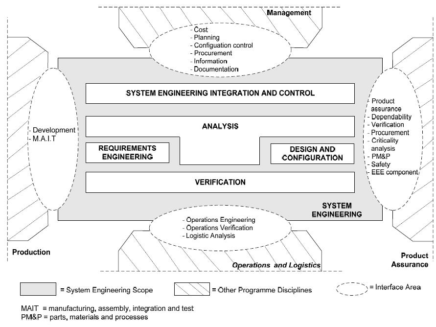
Satellite Engineering PROBA Familly
|
|
|
- Evan Moore
- 6 years ago
- Views:
Transcription

1 Satellite Engineering PROBA Familly Julien Tallineau A presentation to: ULg 12/12/2012 Copyright QinetiQ Limited 2012 QinetiQ Proprietary 1
2 0 TABLE OF CONTENT 1. Introduction 2. PROBA Approach 3. PROBA Satellites 4. PROBA Case Study 5. Conclusions 2

3 1 INTRODUCTION 3

4 1 INTRODUCTION Mandatory Usefull 4
5 1 INTRODUCTION 5
6 1 INTRODUCTION 6
7 1 INTRODUCTION Satellite Engineering 1. Customer Need (Scientist) 2. Creation of System Requirements 3. Phase 0 (CDF Study) 4. Phase A (Feasibility Study) 5. Phase B (Preliminary Design) 6. Phase C (Final Design) 7. Phase D (Manufacturing / Testing) 8. Phase E (Launch / Commissionning/Operations) 9. Phase F (De-orbiting) 7
 2.")
 4.")
8 1 INTRODUCTION Satellite Engineering 1. Customer Need (Scientist) 2. Creation of System Requirements 3. Phase 0 (CDF Study) 4. Phase A (Feasibility Study) 8
9 1 INTRODUCTION Satellite Engineering 5. Phase B (Preliminary Design) Detailed System Analysis Preliminary Subsystem Analysis Trade-offs 6. Phase C (Final Design) Detailed Subsystem Analysis Procurement Qualification testing 9

10 1 INTRODUCTION Satellite Engineering 7. Phase D Manufacturing Acceptance Testing Requirement Verification Shipment to Launch site 10

11 1 INTRODUCTION Satellite Engineering 8. Phase E Launch Commissionning Operations 9. Phase F (De-orbiting/End of Life) None in this case 11

12 2 PROBA APPROACH 12

 Missions In")


13 2 PROBA APPROACH PROBA Philosophy PRoject for On-Board Autonomy (PROBA) Missions In Orbit Demonstration Earth Observation PROBA-1 PROBA-2 Developed under ESA TEC department PROBA-V PROBA-ALTIUS 13

14 2 PROBA APPROACH LightSat Approach In-Orbit Demonstration (IOD) aiming at - Demonstrating new techniques that could lead to new space system - Reduced cost Drastic reduction of the number of requirements Keep the system as simple as possible with only limited inter-dependencies Results rather than paper oriented reviews Accept higher level of risk 14
15 2 PROBA APPROACH Satellite Engineering Tools 1. Requirement Management Tool (DOORS) 2. Mission Analysis Tool (MATLAB) Orbit propagator (J2, Drag, Third Body, SRP) Attitude Control (Magnetic, Nadir, Sun, Target) Incoming fluxes Ground Stations Visibility In orbit Maintainance (To be developed) In orbit Manoeuvering (To be developed) Formation Flying/Rendez vous (To be developed) 15
 IRON-CAD allows for fast iteration PRO-E is similar to CATIA 3.")
16 2 PROBA APPROACH Satellite Engineering Tools 1. Thermal Analysis Tool (ESATAN-TMS) 2. Configuration Tool (IRON-CAD/PRO-E) IRON-CAD allows for fast iteration PRO-E is similar to CATIA 3. Structural Analysis Tool (NASTRAN) 16

17 3 PROBA SATELLITES PROBA 1 PROBA 2 PROBA V 17

18 3 PROBA - 1 PROBA 1 Mission 18


19 3 PROBA - 1 Mission 1. In-orbit demonstration and evaluation of new hardware/software spacecraft technologies and onboard operational autonomy 2. Obrital Parameter 3. Injection Parameter 19
20 3 PROBA - 1 Mission 1. RAAN selected for 10:00 Local Time Descending Node. 20

21 3 PROBA - 1 Mission 1. Launcher is PSLV Nominal separation rate of 2 per sec. Worst Case separation rate of 8 per sec. Inclination accuracy of 0.2 Altitude accuracy of 35km 2. Radiations of 9 krad for 3 years mission Solar maximum is considered 3.5mm of Aluminium considered 21
 30% of all orbits have contact with the ground station (duration > 0 minutes) 21.")
22 3 PROBA - 1 Mission 1. Ground segment visibility (REDU) 30% of all orbits have contact with the ground station (duration > 0 minutes) more than 6 minutes 10.88% more than 8 minutes The longest time between two passes over the ground station is 11hr 44 min 22
23 3 PROBA - 1 Mission 1. Scenario Launch and Early Operation Phase (LEOP) Boot after separation De-tumbling First Ground Contact + AOCS/GPS switched ON Commissioning (two months) Low Autonomy Nominal Operations High Autonomy 23

24 3 PROBA - 1 Satellite Design - Configuration 1. Single H Structure 2. High Unit Density 3. Body Mounted Solar Panel 4. Cut out in panels: Star-Trackers Instruments 24

25 3 PROBA - 1 Satellite Design - Structure 1. Honeycomb panels Aluminium core Aluminium edge Alumiunium facesheet (Primary structure) CFRP facesheet (Secondary structure) 25
26 3 PROBA - 1 Satellite Design - Mechanics 1. Spacecraft Mass = 95 kg 2. Balance Mass of 2.5kg for CoG Location Requirement 26
 in Sun and on Battery in Eclipse Rely on both Battery and SA")
27 3 PROBA - 1 Satellite Design - Power 1. Power budget approach could be: Rely on Solar Array (SA) in Sun and on Battery in Eclipse Rely on both Battery and SA when available. 2. Power budget is positive, independently of the scenario. 27
 Flux margin of 7dB (@max rate = 1Mbps) Flux margin of - 2dB (@min rate = 250kbps) Telemetry Recovery margin of")
28 3 PROBA - 1 Satellite Design RF COM 1. Downlink (S-Band) Flux margin of 7dB (@max rate = 1Mbps) Flux margin of - 2dB (@min rate = 250kbps) Telemetry Recovery margin of 8dB 2. Uplink (S-Band) Carrier Recovery margin of 26dB Telecommand Recovery margin of 17dB 28

29 3 PROBA - 1 Satellite Design Thermal 1. Passive thermal control Thermal Blankets + MLI Black paint (internal panel+electronic box) 29
30 3 PROBA - 1 Satellite Design Data & memory 1. One Image sequence can be stored before next downlink Mass Memory size = 1Gbit Image sequence size = 5 image x 19 spectral lines x 742 spatial lines x 9 kbit/line = 665 Mbit. 2. Data downlinked = 1140Mbit every 12 hours Max data rate Time 1300sec (Total Ground Visibility) 30


31 3 PROBA - 1 Magnetometer (2) (4) GPS RXWheel Rection Magnetotorquer Star-Tracker (3) (4) Measure continuously Takes pictures of starsn the Earth Magnetic and catalog. Zit with field Compare its internat 000satellite km where determine27 itselve the North is. Nthe Compute orientation/position km N km Z Magnetic Coil Align itself to Magnetic lines Accelerates or decelerates while momentum conservation implies the Z PROBA to rotate the other way. determination Position Orientation/Manoeuvre determination Position Orientation/Manoeuvre Orientation/Position
32 3 PROBA - 1 Satellite Design AOCS 1. Guidance = determination of the desired path of travel from the satellite's current location to a designated target 2. Navigation = determination of the satellite s location, velocity and attitude 3. Control Head Head GPS Receiver Star Tracker (2) Magnetometers (2) AOCS Software - Navigation - Guidance - Control Reaction Wheels (4) Magnetotorquers (4) = manipulation of the forces needed to track guidance commands while maintaining satellite stability 32
 Inertial")


33 3 PROBA - 1 Satellite Design AOCS ( Pointing Modes) Inertial Pointing Earth Pointing Point and Stare Scanning Modes Inertial pointing Sun Pointing Utilisation: Astronomy Solar Physics On-track Off-track Utilisation: Earth Observation Telecommunications Space Weather On-track Off-track Utilisation: High Resolution Imaging Elevation Modeling Disaster Monitoring Motion compensation Multiple scans 33
34 3 PROBA - 1 Satellite Design AOCS 1. Specifications Errors at 95% confidence level Absolute Pointing Error (APE) Relative Pointing Error (RPE) Absolute Measurement Error (AME) 100 arcsec 5 arcsec over 10 s 10 arcsec 2. AOCS SW Modes Quiscient Magnetic Celestial Terrestrial Quiscient Mode - No AOCS - Most units are OFF 34
35 3 PROBA - 1 Satellite Design AOCS 1. Specifications Errors at 95% confidence level Absolute Pointing Error (APE) Relative Pointing Error (RPE) Absolute Measurement Error (AME) 100 arcsec 5 arcsec over 10 s 10 arcsec 2. AOCS SW Modes Quiscient Magnetic Celestial Terrestrial Magnetic Mode - Sensor: magnetometer - Actuator: magnetotorquers + 1 RW stby (momentum bias) - Guidance: No - Navigation: No - Control: Bdot Algorithms (Kinetic Energy Dumping) 35
36 3 PROBA - 1 Satellite Design AOCS 1. Specifications Errors at 95% confidence level Absolute Pointing Error (APE) Relative Pointing Error (RPE) Absolute Measurement Error (AME) 100 arcsec 5 arcsec over 10 s 10 arcsec 2. AOCS SW Modes Quiscient Magnetic Celestial Terrestrial Celestial Mode - Sensor: Star-tracker + Magnetic mode sensors - Actuator: Reaction Wheels + Magnetic mode actuatord - Guidance: Sun pointing, Inertial pointing - Navigation: Attitude and Orbit evaluator (Kalman Filter) - Control: State feedback, PID, angular momentum control 36
37 3 PROBA - 1 Satellite Design AOCS 1. Specifications Errors at 95% confidence level Absolute Pointing Error (APE) Relative Pointing Error (RPE) Absolute Measurement Error (AME) 100 arcsec 5 arcsec over 10 s 10 arcsec 2. AOCS SW Modes Quiscient Magnetic Celestial Terrestrial Terrestrial Mode - Sensor: GPS + celestial mode sensors - Actuator: celestial mode actuators - Guidance: Nadir, Fixed-target pointing, Imaging scans - Navigation: Same as Celestial mode - Control: Same as Celestial mode 37


38 3 PROBA - 1 Launched on the 22/10/2001 from India 38
39 3 PROBA - 1 LEOP Activities 1. Rotating Energy is dissipitated progressively using the magneto-torquers. 1,4E-02 Square angular rate (rad/sec) 2 1,2E-02 1,0E-02 8,0E-03 6,0E-03 4,0E-03 2,0E-03 Five hours to detumble! 0,0E+00 0,00 1,00 2,00 3,00 4,00 5,00 6,00 39


40 3 PROBA - 1 Normal Operations Activities Ile de Ré, France 40


41 3 PROBA - 1 Normal Operations Activities Etna eruption, Sicily,

42 3 PROBA - 1 Normal Operations Activities North Sentinel Island India,

43 3 PROBA - 1 Normal Operations Activities Palm Island Dubai 43

44 3 PROBA - 2 PROBA 2 Mission 44

45 3 PROBA - 2 Mission 1. In orbit Demonstration, PROBA-2 aimed at technological innovation. Altogether, 17 new technological developments and four scientific experiments are being flown on Proba Orbital Parameter RAAN selected for 6:00 AM Local Time Ascending Node 45


46 3 PROBA - 2 Mission 1. RAAN selected for 6:00 AM Local Time Ascending Node 46


47 3 PROBA - 2 Mission 1. Launcher is Rockot Worst Case separation rate of 8 per sec. Inclination accuracy of 0.05 Altitude accuracy of 12km RAAN accuracy of 3.75 ( 15min LT) 2. Injected via the Breeze upper stage 47

48 3 PROBA - 2 Mission 48


49 3 PROBA - 2 Mission 1. Ground segment visibility REDU KIROUNA 49
 Nominal Operations 2.")
50 3 PROBA - 2 Mission 1. Scenario LEOP Commissioning (three months) Nominal Operations 2. Spacecraft Modes Separation Safe Observation Stand-by 50
51 3 PROBA - 2 Mission 51


52 3 PROBA - 2 Satellite Design - Configuration 1. Single H Structure 2. Sun Shield Standard STR Bepi-Colombo STR 3. High Unit Density 4. Deployable Solar Panel (x2) 52


")
53 3 PROBA - 1 Satellite Design - Mechanics 1. Spacecraft Mass = kg 2. CoG Choice Folded Configuration (LV requirement) Deployed Configuration (GNC requirement) NB: LV I/F Ring Mass included 53
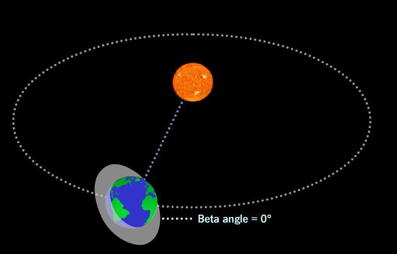
54 3 PROBA - 2 Satellite Design - Power 1. Power budget is positive, independently of the mode Observation (w/o TX Observation with TX Safe mode with TX (worst Beta-angle). Definition Beta Angle = angle between the Sun-Earth vector and the orbital plane. 54


55 3 PROBA - 2 Satellite Design - Power 55
56 3 PROBA - 2 Satellite Design - Power 56


57 3 PROBA - 2 Satellite Design Power 1. Battery DoD (Ah) in function of time 2. Non Regulated bus 28V 57
58 3 PROBA - 2 Satellite Design - Power 1. Power budget while de-tumbling! 2. Trade-off between: Performance (GNC) Time (LEOP schedule) Battery Discharge (Higher DoD) 58

59 3 PROBA - 2 Satellite Design RF COM 59

60 3 PROBA - 2 Satellite Design Thermal 1. Passive thermal control Thermal Blankets + MLI + Chotherm Black paint (internal panel+electronic box) 60

61 3 PROBA - 2 Satellite Design Data & Processing 1. Processing budget shows how busy is the processor with all the units + instruments. On Software Verification Facility On S/C during System Validation Test 5 61
 15W for heater (x2) 50s Isp (min)")
62 3 PROBA - 2 Satellite Design AOCS 1. Low power resistojet (Xenon) 15W for heater (x2) 50s Isp (min) 20mN Thrust Total V = 2m/s 62


63 3 PROBA - 2 Satellite Design AOCS 1. Sensors 2 Star-tracker 2 GPS RX 2 Magnetor-Meter 2. Actuators 4 Reaction Wheels 3 dual-coil magneto-torquer 63

64 4 CASE STUDY: PROBA-3 The Mission Phase A Phase B 64

65 3 PROBA - 3 Mission 1. The PROBA-3 mission will provide an opportunity to validate and develop The Metrology and Actuation techniques / technologies The Guidance strategies and Navigation and Control algorithms necessary for formation flying. 2. One mission, two spacecrafts: Coronagraph S/C (CSC) Occulter SC (OSC) 65
66 3 PROBA - 3 Mission 1. High Elliptical Orbit (HEO) with 20 hours period Low perturbation in Apogee Low AoP drift (fixed above REDU) Limited Eclipse duration Radition Issue Stringent Constraint on RF Link Delta-V issue. Parameter Value Orbit type HEO Perigee altitude 600km Apogee altitude 60530km Inclination 59 Eccentricity AoP 188 RAAN 173 Epoch Jan


67 3 PROBA - 3 Possible Launchers 1. PSLV Launcher Low Cost Heritage from PROBA-1 Reduced Volume 2. Falcon 9 Launcher High Cost Higher Performance Large Volume No Heritage PSLV Falcon 9 67
68 3 PROBA - 3 Which one of the two shall you design your Spacecraft for? 68
69 3 PROBA - 3 Which one of the two shall you design your Spacecraft for? ANSWER = The Two! But it is up to ESA + Delegates to decide the mission budget 69
70 3 PROBA - 3 What would you put in your spacecraft? 70
71 3 PROBA - 3 What would you put in your spacecraft? Subsystem Design Structure Aluminium/CFRP/Invar/Titanium? Thermal Passive/Active? Mechanism Body Mounted/Deployable SA? Power Large/Small SA? Large/Small Battery? GNC RF Payload Sensor? Actuator? High/Low Gain COM Antenna? High/Low Gain FF Antenna? What do you need to perform the mission? 71
72 3 PROBA - 3 Welcome in Phase A! 72


73 3 PROBA 3 Phase A Outcome of Phase A is our STARTING POINT 1. Configuration 2. Mass 3. Power 4. Avionics 5. Thermal 6. Propulsion 7. Link & Data 8. Payload 73


74 3 PROBA 3 Phase A Coronagraph Satellite Overview 1. Twelve subsystems 2. Five entities 74


75 3 PROBA 3 Phase A Coronagraph Satellite Overview 1. From Top 2. From Bottom 75


76 3 PROBA 3 Phase A Coronagraph Satellite Overview 1. From Back Left 2. From Back Right 76


77 3 PROBA 3 Phase A Coronagraph Satellite Overview 1. From Front 2. From Inside 77
. Current estimate: 376.44kg 2.")
78 3 PROBA 3 Phase A Coronagraph Satellite Overview 1. Mass Budget Total CSC dry mass including I/F ring with L/V shall be less than 360kg (with margins). Current estimate: kg 2. Power Budget Total CSC maximum power consumption shall be less than 294W (with margins) Current estimate: W 78
79 3 PROBA 3 Phase A Coronagraph Satellite Overview 1. Avionics Centrilized around Advance Data & Power Management System (ADPMS) Support of Interface Electronics See block diagram 79
80 3 PROBA 3 Phase A Coronagraph Satellite Overview 1. Thermal Solar array temperature range (-169 C to +79 C). Battery operational temperature range: -10 C minimum operational temperature +40 C maximum operational temperature Star Tracker detector maximum operational temperature Current prediction: 40 C Required: 15 C 80
 2x4 thrusters to raise orbit")
 Performance")
81 3 PROBA 3 Phase A Coronagraph Satellite Overview 1. Propulsion System (HPGP) 2x4 thrusters to raise orbit Constrains Pre-warming needs 64W (=2x4x8W) during 30 min Propellant needs to be kept above 10 C (Always) Performance Isp = 202 EoL Thrust = 1N 81


82 3 PROBA 3 Phase A Coronagraph Satellite Overview 1. Propulsion System (Cold Gas) Siwteen thruster for GNC and FF Performance 82
83 3 PROBA 3 Phase A Coronagraph Satellite Overview 1. GNC Sensors 6 Sun Acquisition Sensors 2x3 Gyros 2x3 Acceleromter 3 Star Trackers Head + 2x1 Electronics 2x1 GPS 3. GNC FF Omni-directional RF Sensor (FFRF) Coarse Lateral Sensor Fine Formation Sensor 2. GNC Actuators 3+1 Reaction Wheels Cold Gas thrusters 83
84 3 PROBA 3 Phase A Coronagraph Satellite Overview 1. Link Budget The CSC shall be able to downlink data at a symbol rates of 256ksps and 2Msps using REDU-3 Ground Station The CSC shall be able to receive TC data at a symbol rates of 64ksps using REDU-3 Ground Station Current estimation: Downlink not closed for 2Msps (@apogee) Uplink not closed for 64ksps (@apogee) 84
85 Daily Coverage Percentage 3 PROBA 3 Phase A Coronagraph Satellite Overview 1. Data Budget The CSC shall be able to downlink 8.5Gbit of data per day Current estimate Min rate (256ksps) 100,00% 90,00% Coverage Percentage Needed for Downlink of CORONAGRAPH data (8.5GBit/Daily) Max rate (2Msps) 80,00% 70,00% 60,00% 50,00% 40,00% 30,00% 20,00% 10,00% 0,00% COR Altitude (1000 km) Redu Coverage Redu+Santiago+Perth Coverage Needed Coverage Percentage Low Rate DL (8.5GBit Data/24h) Needed Coverage Percentage High Rate DL (8.5GBit Data/24h) 85

86 3 PROBA 3 Phase A SUMMARY 1. Satellite is too heavy 2. Satellite is too power consuming 3. Satellite is too hot or too cold 4. Satellite is too far to close its downlink and uplink 5. Satellite is too far to downlink its science data 6. Satellite is too un-protected wrt radiations (20krad under 2mm Al) 86
87 3 PROBA - 3 What can we do? 87

88 3 PROBA 3 Phase A ANSWER 1. Mass & Power reduction exercise 2. Perform a detailed thermal analysis Active control Electronics Location Radiator size 3. Review Operation concept for U/D link 4. Increase Satellite Shielding + MINIMIZE THE COST! 88
89 3 PROBA - 3 Welcome in Phase B! 89

90 3 PROBA 3 Phase B Mass reduction 1. Who are the biggest contributors? Structure Formation Flying Propulsion System Payload 90
91 3 PROBA - 3 What can we do? 91
92 3 PROBA 3 Phase B Mass reduction 1. Structure Shield the spacecraft with outer panels! Remove materials in the Bottom Board! Remove two panels while re-arranging structure Shorten the satellite Consider LV I/F ring as part of system mass margin 3. Payload Replace the FFRF Shorten Payload 4. Other Direct Injection! 2. GNC & Propulsion Remove the Accelerometer Remove Cold Gas Propulsion System (Transfer to OSC) Include 2x4 additional HPGP thruster for 6DoF 92
 Honeycomb Al-Al-Al (Primary & Secondary Structure ) Honeycomb CFRP-Al-CFRP (Solar Cells")
93 3 PROBA 3 Phase B Mass reduction results 1. Structure has been reinforced (corner bracket) Honeycomb Al-Al-Al (Primary & Secondary Structure ) Honeycomb CFRP-Al-CFRP (Solar Cells accommodation) 2. Satellite has better shielding 3. Mass has decreased to 318kg See Mass Budget 93
94 3 PROBA 3 Phase B Power reduction 1. Who are the biggest contributors? Thermal control = 91W (due to propellant thermal constraint) Propulsion (HPGP) = 128W (16x8W after the mass reduction) Payload = 40W (pre-warming) Reaction Wheel = 42W (when 3 accelerating + 1 constant speed) 2. Still to be included within the 294W 30% 43% 13% 13% 99% STR / Gyro / GPS / RF systems / On-Board Computer / Propulsion Electronics / 94
95 3 PROBA 3 Phase B Power reduction 1. Who are the biggest contributors? Thermal control = 91W (due to propellant thermal constraint) Propulsion (HPGP) = 128W (16x8W after the mass reduction) Payload = 40W (pre-warming) Reaction Wheel = 42W (when 3 accelerating + 1 constant speed) 2. Still to be included within the 294W 30% 43% 13% 13% 99% STR / Gyro / GPS / RF systems / On-Board Computer / Propulsion Electronics / What would do a good system engineer? 95
96 3 PROBA 3 Phase B Power reduction 1. Thermal Control Satellite wrapped into MLI Electronics as close as possible to cold points 2. Propulsion Only half of thruster pre-warmed + duty cycle Only less than half the power is given at the same time (longer pre-warming!) 3. Payload Longer pre-warming 4. GNC FFRF removed 96
97 3 PROBA 3 Phase B Power reduction 1. Thermal Control reduced to 75W (instead of 91W) 2. Propulsion reduced to 33,6W (instead of 128W) 3. Payload reduced to 10W (instead of 40W) 97
98 3 PROBA 3 Phase B Power reduction 1. Thermal Control reduced to 75W (instead of 91W) 2. Propulsion reduced to 33,6W (instead of 128W) 3. Payload reduced to 10W (instead of 40W) What is the next step? 98
99 3 PROBA 3 Phase B Electrical Architecture 1. Power Generation & Storage Solar Array Battery 2. Power Conditioning Distribution Unit ADPMS 3. Connections Safe & Arm Umbilical Connection 99
100 3 PROBA 3 Phase B Solar Array Design 1. Main components Cells Series (TBD) String Parallel (TBD) 6xSection (TBD strings) 2. Secondary components Shunt Selection Dump Resistor 100
101 3 PROBA 3 Phase B Solar Array Design 1. Main components How can we calculate this? Cells Series (TBD) String Parallel (TBD) 6xSection (TBD strings) 2. Secondary components Shunt Selection Dump Resistor 101
102 3 PROBA 3 Phase B Solar Array Design (3G28%) 1. Evaluate the degradation? Coverglass thickness Degradation of Electrical Parameters Degradation of Temp. Coefficient 102
 1.")


103 3 PROBA 3 Phase B Solar Array Design (3G28%) 1. Evaluate the degradation? Coverglass thickness Degradation of Electrical Parameters Degradation of Temp. Coefficient 103

104 3 PROBA 3 Phase B Solar Array Design 2. Evaluate the number of cells? Max battery voltage to be provided (29.4V) Compute all voltage drop Compute number of cells (MPP) 18 Cells / Strings 104
105 3 PROBA 3 Phase B Solar Array Design 3. Evaluate the number of strings? Max current allowed by ADPMS (12A) Compute string current EoL ( di/dt < 0) Minimum Solar Cste (di/dc > 0) Operating temperature (di/dt>0 but du/dt<<0) Operating point 105
 Compute string current EoL ( di/dt < 0) Minimum Solar Cste (di/dc > 0) Operating temperature")
106 3 PROBA 3 Phase B Solar Array Design 3. Evaluate the number of strings? Max current allowed by ADPMS (12A) Compute string current EoL ( di/dt < 0) Minimum Solar Cste (di/dc > 0) Operating temperature (di/dt>0 but du/dt<<0) Operating point 23 (+1) Strings 106
107 3 PROBA 3 Phase B Solar Array Design 4. Evaluate the Power available? Power = Current * Voltage 1 String Failure Tolerance 107

108 3 PROBA 3 Phase B Solar Array Design 4. Evaluate the Power available? Power = Current * Voltage 1 String Failure Tolerance 108
109 3 PROBA - 3 What if GNC has a failure? 109
110 3 PROBA - 3 What if GNC has a failure? ANSWER = Need to be taken into account if pointing accuracy of SUN POINTING is decreased! 110
111 3 PROBA 3 Phase B Battery Design 1. Main components Cells Series (TBD) String Parallel (TBD) 2. Secondary components Internat heaters Thermistors 111
112 3 PROBA 3 Phase B Battery Design 1. Main components How can we calculate this? Cells Series (TBD) String Parallel (TBD) 2. Secondary components Internat heaters Thermistors 112
 7 Cells / String Cells characteristics (4.2V EoC) 4.2 4.1 4.0 3.9 3.8 3.7 3.6 3.5 3.4 3.3 3.2 3.1 3.0 2.9 2.8 2.7 2.6 2.")
113 Cell Level EMF (V) 3 PROBA 3 Phase B Battery Design 1. Evaluate the number of cells? Nominal non regulated bus voltage (28V) 7 Cells / String Cells characteristics (4.2V EoC) State of Charge (%) Discharge EMF Charge EMF 113
 Detumbling (200W /")
114 3 PROBA 3 Phase B Battery Design 2. Evaluate the number of strings? Approach decision Battery for both Sun & Eclipse Battery for Eclipse only Check Power Budget (Wst Case) Detumbling (200W / 1hr) Eclipse (240W / 30min) Long Eclipse (190W / 3.5hrs) 114
115 3 PROBA 3 Phase B Battery Design 2. Evaluate the number of strings? Capacity used = Power * Time Capacity required = Capacity Used *(1+DoD) Capacity of 1 string = Nb Cells *Capacity Cell One String Failure Tolerance Scenario Used Capacity (Wh) Detumbling 200 Eclipse 120 Long Eclipse 665 Scenario DoD choice Required Capacity (Wh) Detumbling 20% 240 Eclipse 20% 148 Long Eclipse 60% (+1) Strings Parameter Value Nb Cells 7 Capacity Cell 5,4 Wh Capacity 1 string 37,8 Wh 115
116 3 PROBA 3 Phase B U/D Operational Concept Problems 1. Downlink not closed at apogee at Max Rate 2. Uplink not closed at apogee at Max Rate 3. Data not able to be downlinked below 50kkm at max rate (coverage) 4. Data not able to be downlinked at min rate (coverage) See Link Budget 116
117 3 PROBA - 3 What can we do? 117
118 3 PROBA 3 Phase B U/D Operational Concept Solutions 1. Use more Ground Segment 2. Use more Space Segment 3. Use one/several high gain Space Segment 4. Use variable data rate Low Rate (Uplink & Downlink) when at apogee High rate (Uplink & Downlink) when at perigee 118
119 3 PROBA 3 Phase B U/D Operational Concept Solutions 1. Use more Ground Segment What is the consequence? 2. Use more Space Segment 3. Use one/several high gain Space Segment 4. Use variable data rate What is the consequence? Low Rate (Uplink & Downlink) when at apogee High rate (Uplink & Downlink) when at perigee 119

120 3 PROBA - 3 Results! 120
121 3 PROBA 3 Phase B Updated Block Diagram 121

122 3 PROBA 3 Phase B Updated Configuration 122

123 3 PROBA 3 Phase B Updated Configuration 123

124 3 PROBA 3 Phase B Updated Configuration 124

125 3 PROBA 3 Phase B Final Stack Configuration 1. Occulter Spacecraft 2. Coronagraph Spacecraft 125

126 3 PROBA - 3 How would you now further reduce the cost? 126
127 3 PROBA - 3 How would you now reduce the cost? ANSWER = Increase the risk! 127

128 4 CONCLUSION 128
129 4 Conclusion Satellite System Engineering 1. Follows the Project Life Cycle Starts with Mission Concept Prepares System Requirements Proposes System Designs based on Trade-Offs (Technical + Programmatics) Manufacture the S/C Verify Requirements (Review of Design / Analysis / Test) Launch it! 2. Iterative Multi-disciplinary approach + Massive Communication 129

130 4 Conclusion QinetiQ Space 1. Proposes Fast Learning Curve on Satellite Systems 2. Offers possibility to built international network quickly 3. Provides opportunity to be known at the European Space Agency 130
131 131
Satellite Engineering PROBA Family
 Satellite Engineering PROBA Family Julien Tallineau A presentation to: ULg 09/12/2013 Ir. Julien Tallineau Satellite System Engineer Tel: +32 3 250 14 14 (general) Tel: +32 3 250 43 43 (direct) Fax:+32
Satellite Engineering PROBA Family
 Satellite Engineering PROBA Family Ir. Julien Tallineau Business Development Manager Tel: +32 3 250 14 14 (general) Tel: +32 3 250 43 43 (direct) Fax:+32 3 253 14 64 Julien.tallineau@qinetiq.be Presentation
Formation Flying Experiments on the Orion-Emerald Mission. Introduction
 Formation Flying Experiments on the Orion-Emerald Mission Philip Ferguson Jonathan P. How Space Systems Lab Massachusetts Institute of Technology Present updated Orion mission operations Goals & timelines
CALL FOR IDEAS FOR THE RE-USE OF THE MARS EXPRESS PLATFORM PLATFORM CAPABILITIES. D. McCoy
 Mars Express Reuse: Call for Ideas CALL FOR IDEAS FOR THE RE-USE OF THE MARS EXPRESS PLATFORM PLATFORM CAPABILITIES D. McCoy PARIS 23 MARCH 2001 page 1 Mars Express Reuse: Call for Ideas PRESENTATION CONTENTS
Baseline Concepts of the Kayser-Threde Team
 Kayser-Threde GmbH Space Industrial Applications e.deorbit Mission Phase A Baseline Concepts of the Kayser-Threde Team 6 May 2014, Conference Centre Leeuwenhorst, The Netherlands Agenda Introduction Target
Preliminary Design of the Electrical Power Subsystem for the European Student Moon Orbiter Mission
 Preliminary Design of the Electrical Power Subsystem for the European Student Moon Orbiter Mission Steve Ulrich Jean-François Veilleux François Landry Corbin Picture courtesy of ESA Presentation Outline
Michael J. Cully Director of Civil and Commercial Space Swales Aerospace Beltsville, Maryland
 SSC03-IX-7 I-CONE FOR RAPID RESPONSE AND LOW COST ACCESS TO SPACE 1 Director of Civil and Commercial Space Swales Aerospace Beltsville, Maryland Peter Alea Manager of Thermal Products Swales Aerospace
Results of the Airbus DS led e.deorbit Phase B1 ESA study. Dr.-Ing. Stéphane Estable ESA Clean Space Industrial Days, October 2017
 Results of the Airbus DS led e.deorbit Phase B1 ESA study Dr.-Ing. Stéphane Estable ESA Clean Space Industrial Days, 24-26 October 2017 2 e.deorbit Mission Final rendezvous and capture phase Phase B1 Team
OLEV AN ON-ORBIT SERVICING PROGRAM FOR COMMERCIAL SPACECRAFTS IN GEO
 Von der Erde ins All. Und zurück. Intelligente Lösungen für Industrie und Wissenschaft. From Earth to Space. And back. Intelligent solutions for industry and science. E a r t h S p a c e & F u t u r e
OMOTENASHI. (Outstanding MOon exploration TEchnologies demonstrated by NAno Semi-Hard Impactor)
") SLS EM-1 secondary payload OMOTENASHI (Outstanding MOon exploration TEchnologies demonstrated by NAno Semi-Hard Impactor) The smallest moon lander launched by the most powerful rocket in the world * Omotenashi
SLS EM-1 secondary payload OMOTENASHI (Outstanding MOon exploration TEchnologies demonstrated by NAno Semi-Hard Impactor) The smallest moon lander launched by the most powerful rocket in the world * Omotenashi
EPIC Workshop 2017 SES Perspective on Electric Propulsion
 EPIC Workshop 2017 SES Perspective on Electric Propulsion PRESENTED BY Eric Kruch PRESENTED ON 24 October 2017 SES Proprietary SES Perspective on Electric Propulsion Agenda 1 Electric propulsion at SES
Palamede, more than a microsatellite. Workshop on University Micro Satellites in Italy Rome, July 27, 2005
 Palamede, more than a microsatellite The Palamede Team (represented by Franco Bernelli and Roberto Armellin) Workshop on University Micro Satellites in Italy Rome, July 27, 2005 Outline Mission and educational
THE KOREASAT5 PROGRAM
 THE KOREASAT5 PROGRAM - Design, AI&T, Launch and Operation KT CORPORTION Contents I. Introduction II. Design III. Assembly, Integration and Test (AI&T) IV. Launch V. Operation VI. Q & A THE KOREASAT 5
EPIC Gap analysis and results
 EPIC Gap analysis and results PSA Consortium Workshop Stockholm 11/02/2015 EPIC Gap Analysis and results/ Content Content: Scope Process Missions Analysis (i.e GEO (OR + SK)) Gaps results Gap analysis
The GHOST of a Chance for SmallSat s (GH2 Orbital Space Transfer) Vehicle
 Vehicle") The GHOST of a Chance for SmallSat s (GH2 Orbital Space Transfer) Vehicle Dr. Gerard (Jake) Szatkowski United launch Alliance Project Mngr. SmallSat Accommodations Bernard Kutter United launch Alliance
The GHOST of a Chance for SmallSat s (GH2 Orbital Space Transfer) Vehicle Dr. Gerard (Jake) Szatkowski United launch Alliance Project Mngr. SmallSat Accommodations Bernard Kutter United launch Alliance
The DoD Space Test Program Standard Interface Vehicle (ESPA) Class Program
 Class Program") The DoD Space Test Program Standard Interface Vehicle (ESPA) Class Program Mr. Mike Marlow STP-SIV Program Manager Co-Authors Lt Col Randy Ripley Capt Chris Badgett Ms. Hallie Walden 20 th Annual AIAA/USU
The DoD Space Test Program Standard Interface Vehicle (ESPA) Class Program Mr. Mike Marlow STP-SIV Program Manager Co-Authors Lt Col Randy Ripley Capt Chris Badgett Ms. Hallie Walden 20 th Annual AIAA/USU
FlexCore Low-Cost Attitude Determination and Control Enabling High-Performance Small Spacecraft
 FlexCore Low-Cost Attitude Determination and Control Enabling High-Performance Small Spacecraft Dan Hegel Director, Advanced Development Blue Canyon Technologies hegel@bluecanyontech.com BCT Overview BCT
Lunette: A Global Network of Small Lunar Landers
 Lunette: A Global Network of Small Lunar Landers Leon Alkalai and John O. Elliott Jet Propulsion Laboratory California Institute of Technology LEAG/ILEWG 2008 October 30, 2008 Baseline Mission Initial
System Testing by Flight Operators the Rosetta Experience
 European Space Operations Center System Testing by Flight Operators the Rosetta Experience E. Montagnon, P. Ferri, L. O Rourke, A. Accomazzo, I. Tanco, J. Morales, M. Sweeney Spaceops 2004, Montréal, Canada,
ANTENNA SCAN MECHANISM FOR AN INTER SATELLITE LINK OF A CONSTELLATION PROGRAM
 ANTENNA SCAN MECHANISM FOR AN INTER SATELLITE LINK OF A CONSTELLATION PROGRAM Ingo Köker, AIRBUS DS GmbH, ingo.koeker@airbus.com Frank Härtel, AIRBUS DS GmbH, frank.haertel@airbus.com Abstract For a constellation
ORBITAL EXPRESS Space Operations Architecture Program 17 th Annual AIAA/USU Conference on Small Satellites August 12, 2003
 ORBITAL EXPRESS Space Operations Architecture Program 17 th Annual AIAA/USU Conference on Small Satellites August 12, 2003 Major James Shoemaker, USAF, Ph.D. DARPA Orbital Express Space Operations Program
Adrestia. A mission for humanity, designed in Delft. Challenge the future
 Adrestia A mission for humanity, designed in Delft 1 Adrestia Vision Statement: To inspire humanity by taking the next step towards setting a footprint on Mars Mission Statement Our goal is to design an
ASTRIUM. Lunar Lander Concept for LIFE. Hansjürgen Günther TOB 11. Bremen, 23/
 Lunar Lander Concept for LIFE Hansjürgen Günther TOB 11 Bremen, 23/24.11.2006 This document is the property of EADS SPACE. It shall not be communicated to third parties without prior written agreement.its
First results and next steps in Kazakhstan Earth Observation missions in cooperation with SSTL
 First results and next steps in Kazakhstan Earth Observation missions in cooperation with SSTL M.Moldabekov (1), M.Nurguzhin (2), V.Ten (3), S.Murushkin (3), H.Lambert (3), A.da Silva Curiel (4), D.King
SMARTSat. Shape Memory Alloy Research Technology Satellite. Allison Barnard Alicia Broederdorf. Texas A&M University Space Engineering Institute
 SMARTSat Shape Memory Alloy Research Technology Satellite Allison Barnard Alicia Broederdorf Texas A&M University Space Engineering Institute Outline Introduction / Mission Objectives Systems Overview
European Lunar Lander: System Engineering Approach
 human spaceflight & operations European Lunar Lander: System Engineering Approach SECESA, 17 Oct. 2012 ESA Lunar Lander Office European Lunar Lander Mission Objectives: Preparing for Future Exploration
USA FALCON 1. Fax: (310) Telephone: (310) Fax: (310) Telephone: (310) Fax: (310)
 Telephone: (310) Fax: (310) Telephone: (310) Fax: (310)") 1. IDENTIFICATION 1.1 Name FALCON 1 1.2 Classification Family : FALCON Series : FALCON 1 Version : FALCON 1 Category : SPACE LAUNCH VEHICLE Class : Small Launch Vehicle (SLV) Type : Expendable Launch Vehicle
1. IDENTIFICATION 1.1 Name FALCON 1 1.2 Classification Family : FALCON Series : FALCON 1 Version : FALCON 1 Category : SPACE LAUNCH VEHICLE Class : Small Launch Vehicle (SLV) Type : Expendable Launch Vehicle
Thinking Outside the Cube
 CHANGING THE ECONOMICS OF SPACE Thinking Outside the Cube 34 th Space Symposium Colorado Springs Monday 16 th April 2018 Anita Bernie a.bernie@sstl.co.uk Commercial in Confidence. SSTL 2017 SpaceNews Home
The European Lunar Lander Mission
 The European Lunar Lander Mission Alain Pradier ASTRA Noordwijk, 12 th April 2011 European Space Agency Objectives Programme Objective PREPARATION FOR FUTURE HUMAN EXPLORATION Lunar Lander Mission Objective
Rocket 101. IPSL Space Policy & Law Course. Andrew Ratcliffe. Head of Launch Systems Chief Engineers Team
 Rocket 101 IPSL Space Policy & Law Course Andrew Ratcliffe Head of Launch Systems Chief Engineers Team Contents Background Rocket Science Basics Anatomy of a Launch Vehicle Where to Launch? Future of Access
Thinking Outside the Cube
 Thinking Outside the Cube Anita Bernie 1, Alex da Silva Curiel 1, Nikki Antoniou 1, Luis Gomes 1, Rob Goddard 1, Jonathan Friend 1, Sir Martin Sweeting 2 1) Surrey Satellite Technology Ltd., Tycho House,
On the feasibility of a fast track return to Mars
 On the feasibility of a fast track return to Mars Mars Lander(s) 2011 Mars Demonstration Landers (MDL) Page 1 Technology Demonstrators SMART 1 SMART 2 LISA PF Solar Electric Propulsion Drag Free Control
In-Space Demonstration of HighPerformance Green Propulsion (HPGP) and its Impact on Small Satellites
 and its Impact on Small Satellites") In-Space Demonstration of HighPerformance Green Propulsion (HPGP) and its Impact on Small Satellites Ben Crowe and Kjell Anflo 25 th Annual AIAA/Utah State University Conference on Small Satellites 10th
In-Space Demonstration of HighPerformance Green Propulsion (HPGP) and its Impact on Small Satellites Ben Crowe and Kjell Anflo 25 th Annual AIAA/Utah State University Conference on Small Satellites 10th
Exomars Orbiter Module Bus OMB
 Exomars Orbiter Module Bus OMB TAS-F 23rd Sept 2010 Exomars Industrial day- Turin 1 Exomars OMB definition Exomars OMB will: serve as a carrier to deliver the EDM at the right landing latitude in the 2016
r bulletin 96 november 1998 Figure 1. Overall ATV configuration (ESA/D. Ducros)
") r bulletin 96 november 1998 Figure 1. Overall ATV configuration (ESA/D. Ducros) atv The Automated Transfer Vehicle P. Amadieu Head of ATV/CTV Projects Division, ESA Directorate of Manned Spaceflight and
r bulletin 96 november 1998 Figure 1. Overall ATV configuration (ESA/D. Ducros) atv The Automated Transfer Vehicle P. Amadieu Head of ATV/CTV Projects Division, ESA Directorate of Manned Spaceflight and
EuLISA. <Chemical Propulsion> Internal Final Presentation ESTEC, 8 July Prepared by the ICPA / CDF* Team. (*) ESTEC Concurrent Design Facility
 ESTEC Concurrent Design Facility") EuLISA Internal Final Presentation ESTEC, 8 July 2011 Prepared by the ICPA / CDF* Team (*) ESTEC Concurrent Design Facility Option 1 First table in MA presentation: Delta-v budget
EuLISA Internal Final Presentation ESTEC, 8 July 2011 Prepared by the ICPA / CDF* Team (*) ESTEC Concurrent Design Facility Option 1 First table in MA presentation: Delta-v budget
SOYUZ-IKAR-FREGAT 1. IDENTIFICATION. 1.1 Name. 1.2 Classification Family : SOYUZ Series : SOYUZ Version : SOYUZ-IKAR SOYUZ-FREGAT
 1. IDENTIFICATION 1.1 Name 1.2 Classification Family : SOYUZ Series : SOYUZ Version : SOYUZ-IKAR SOYUZ-FREGAT Category : SPACE LAUNCH VEHICLE Class : Medium Launch Vehicle (MLV) Type : Expendable Launch
LUNAR INDUSTRIAL RESEARCH BASE. Yuzhnoye SDO proprietary
 LUNAR INDUSTRIAL RESEARCH BASE DESCRIPTION Lunar Industrial Research Base is one of global, expensive, scientific and labor intensive projects which is to be implemented by the humanity to meet the needs
1 Evaluation of Power Control System for Micro and Nano Satellites by Hardware-in-the-Loop Simulator
 1 Evaluation of Power Control System for Micro and Nano Satellites by Hardware-in-the-Loop Simulator Yuji Sakamoto, Toshinori Kuwahara, et al. Tohoku University, Japan 16 AUG 2012 Small Satellite Conference
Super Squadron technical paper for. International Aerial Robotics Competition Team Reconnaissance. C. Aasish (M.
 Super Squadron technical paper for International Aerial Robotics Competition 2017 Team Reconnaissance C. Aasish (M.Tech Avionics) S. Jayadeep (B.Tech Avionics) N. Gowri (B.Tech Aerospace) ABSTRACT The
The Common Spacecraft Bus and Lunar Commercialization
 The Common Spacecraft Bus and Lunar Commercialization Alex MacDonald NASA Ames Research Center alex.macdonald@balliol.ox.ac.uk Will Marshall NASA Ames Research Center william.s.marshall@nasa.gov Summary
INTERNATIONAL LUNAR NETWORK ANCHOR NODES AND ROBOTIC LUNAR LANDER PROJECT UPDATE
 INTERNATIONAL LUNAR NETWORK ANCHOR NODES AND ROBOTIC LUNAR LANDER PROJECT UPDATE NASA/ Barbara Cohen Julie Bassler Greg Chavers Monica Hammond Larry Hill Danny Harris Todd Holloway Brian Mulac JHU/APL
QinetiQ Electric Propulsion
 QinetiQ Electric Propulsion Gridded Ion Thruster developments Kevin Hall EPIC Madrid, Spain 24 th & 25 th October, 2017 QinetiQ Introduction QinetiQ employs over 6,000 experts in the fields of defence,
Pathfinder Technology Demonstrator
 Demonstrating Advanced Technologies for Advanced Missions CubeSat Developer s Workshop April 26 th, 2017 NASA Space Technology Mission Directorate NASA Small Spacecraft Technology Program NASA Ames Research
THE FIRST IN-SPACE DEMONSTRATION OF A GREEN PROPULSION SYSTEM
 THE FIRST IN-SPACE DEMONSTRATION OF A GREEN PROPULSION SYSTEM Presented by: Mathias Persson, CEO ECAPS, Solna, Sweden SSC10-XI-2 Copyright 2010 ECAPS - 1 - Outline 1. Introduction 2. Objectives 3. PRISMA
NEXT Exploration Science and Technology Mission. Relevance for Lunar Exploration
 NEXT Exploration Science and Technology Mission Relevance for Lunar Exploration Alain Pradier & the NEXT mission team ILEWG Meeting, 23 rd September 2007, Sorrento AURORA PROGRAMME Ministerial Council
Spacecraft Power Systems
 Spacecraft Power Systems The Generation and Storage of Electrical Power D. B. Kanipe Aero 401 February 9, 2016 Power Systems Batteries Solar Cells + Batteries Fuel Cells RTG Nuclear Reactors? Functions
Solely EP based Orbit Control System on Small GEO Satellite
 Solely EP based Orbit Control System on Small GEO Satellite IEPC-2007-274 30 th International Electric Propulsion Conference, Florence, Italy H. Lübberstedt *, Th. Miesner, A. Winkler OHB-System AG, D-28359
Europa Lander. Mission Concept Update 3/29/2017
 Europa Lander Mission Concept Update 3/29/2017 2017 California Institute of Technology. Government sponsorship acknowledged. 1 Viable Lander/Carrier Mission Concept Cruise/Jovian Tour Jupiter orbit insertion
ELECTRIC PROPULSION MISSION TO GEO USING SOYUZ/FREGAT LAUNCH VEHICLE M.S. Konstantinov *, G.G. Fedotov *, V.G. Petukhov ±, G.A.
 ELECTRIC PROPULSION MISSION TO GEO USING SOYUZ/FREGAT LAUNCH VEHICLE M.S. Konstantinov *, G.G. Fedotov *, V.G. Petukhov ±, G.A. Popov * Moscow Aviation Institute, Moscow, Russia ± Khrunichev State Research
Bi-Axial Solar Array Drive Mechanism: Design, Build and Environmental Testing
 Bi-Axial Solar Array Drive Mechanism: Design, Build and Environmental Testing Noémy Scheidegger*, Mark Ferris* and Nigel Phillips * Abstract The development of the Bi-Axial Solar Array Drive Mechanism
The SHuttle Expendable Rocket for Payload Augmentation (SHERPA)
") The SHuttle Expendable Rocket for Payload Augmentation (SHERPA) Aaron Rogers, Paul Gloyer, Randall Carlson, Steve Buckley SSC03-II-2 August 12 th, 2003 Overview Introduction Mission Requirements Description
The SHuttle Expendable Rocket for Payload Augmentation (SHERPA) Aaron Rogers, Paul Gloyer, Randall Carlson, Steve Buckley SSC03-II-2 August 12 th, 2003 Overview Introduction Mission Requirements Description
THE FALCON I LAUNCH VEHICLE Making Access to Space More Affordable, Reliable and Pleasant
 18 th Annual AIAA/USU Conference on Small Satellites SSC04-X-7 THE FALCON I LAUNCH VEHICLE Making Access to Space More Affordable, Reliable and Pleasant Hans Koenigsmann, Elon Musk, Gwynne Shotwell, Anne
SMALLSAT PROPULSION. Pete Smith, Roland McLellan Marotta UK Ltd, Cheltenham, and Dave Gibbon SSTL, Guildford, UK.
 SMALLSAT PROPULSION Pete Smith, Roland McLellan Marotta UK Ltd, Cheltenham, and Dave Gibbon SSTL, Guildford, UK. ABSTRACT This paper presents an overview of the components, systems and technologies used
Pre-Launch Procedures
 Pre-Launch Procedures Integration and test phase This phase of operations takes place about 3 months before launch, at the TsSKB-Progress factory in Samara, where Foton and its launch vehicle are built.
The Mars Express Mission A Continuing Challenge. Erhard Rabenau, NOVA Space Associates Ltd Mars Express Senior Mission Planner
 The Mars Express Mission A Continuing Challenge Erhard Rabenau, NOVA Space Associates Ltd Mars Express Senior Mission Planner Mars Society, Munich, 13 October, 2012 The Mars Express Mission - a First in
Upper Stage Evolution
 Upper Stage Evolution Mark Wilkins Atlas Product Line VP United Launch Alliance AIAA_JPC080309 Copyright 2009 United Launch Alliance, LLC. All Rights Reserved. EELV Sustainment Through 2030 ULA s Evolution
Seminar 12! The Future of Space Flight! Spacecraft Power & Thermal Control!
 Seminar 12! The Future of Space Flight! Spacecraft Power & Thermal Control! Robert Stengel! FRS 112, From the Earth to the Moon! Princeton University, 2015! " NASA s Strategic Direction! Rationales and
NASA s Choice to Resupply the Space Station
 RELIABILITY SpaceX is based on the philosophy that through simplicity, reliability and low-cost can go hand-in-hand. By eliminating the traditional layers of management internally, and sub-contractors
The Falcon 1 Flight 3 - Jumpstart Mission Integration Summary and Flight Results. AIAA/USU Conference on Small Satellites, 2008 Paper SSC08-IX-6
 The Falcon 1 Flight 3 - Jumpstart Mission Integration Summary and Flight Results Aug. 13, 2008 AIAA/USU Conference on Small Satellites, 2008 Paper SSC08-IX-6 Founded with the singular goal of providing
Deployment and Flight Test of Inflatable Membrane Aeroshell using Large Scientific Balloon
 1 Deployment and Flight Test of Inflatable Membrane Aeroshell using Large Scientific Balloon Kazuhiko Yamada, Takashi Abe (JAXA/ISAS) Kojiro Suzuki, Naohiko Honma, Yasunori Nagata, Masashi Koyama (The
Cal Poly CubeSat Workshop 2014
 Cal Poly CubeSat Workshop 2014 866.204.1707 www.spaceflightservices.com info@spaceflightservices.com hhh @spaceflightinc 1 Spaceflight Business Model Our Model Arrange launch opportunities for secondary
Canisterized Satellite Dispenser (CSD) As A Standard For Integrating and Dispensing Hosted Payloads on Large Spacecraft and Launch Vehicles
 As A Standard For Integrating and Dispensing Hosted Payloads on Large Spacecraft and Launch Vehicles") Canisterized Satellite Dispenser (CSD) As A Standard For Integrating and Dispensing Hosted Payloads on Large Spacecraft and Launch Vehicles Ryan Hevner, Ryan Williams and (Presented by) Walter Holemans
Canisterized Satellite Dispenser (CSD) As A Standard For Integrating and Dispensing Hosted Payloads on Large Spacecraft and Launch Vehicles Ryan Hevner, Ryan Williams and (Presented by) Walter Holemans
SAFT VES16 SOLUTION FOR SMALL GEO
 SAFT VES16 SOLUTION FOR SMALL GEO Emmanuel Bonneau (1), Stéphane Remy (1) (1) Saft, Space and Defence Division, Rue Georges Leclanché 86060 Poitiers France, Email: emmanuel.bonneau@saftbatteries.com, stephane.remy@saftbatteries.com
NASA Glenn Research Center Intelligent Power System Control Development for Deep Space Exploration
 National Aeronautics and Space Administration NASA Glenn Research Center Intelligent Power System Control Development for Deep Space Exploration Anne M. McNelis NASA Glenn Research Center Presentation
H-IIA Launch Vehicle Upgrade Development
 26 H-IIA Launch Vehicle Upgrade Development - Upper Stage Enhancement to Extend the Lifetime of Satellites - MAYUKI NIITSU *1 MASAAKI YASUI *2 KOJI SHIMURA *3 JUN YABANA *4 YOSHICHIKA TANABE *5 KEITARO
Development of a Low Cost Suborbital Rocket for Small Satellite Testing and In-Space Experiments
 Development of a Low Cost Suborbital Rocket for Small Satellite Testing and In-Space Experiments Würzburg, 2015-09-15 (extended presentation) Dr.-Ing. Peter H. Weuta Dipl.-Ing. Neil Jaschinski WEPA-Technologies
Lunar Science and Infrastructure with the Future Lunar Lander
 ICEUM9 Sorrento Lunar Science and Infrastructure with the Future Lunar Lander Session 9: Next steps for Robotic Landers, Rovers and Outposts ICEUM9 Sorrento, Oct. 26, 2007 Hansjürgen Günther 26/10/2007
The 1 N HPGP thruster is designed for attitude and orbit control of small-sized satellites. FLIGHT-PROVEN. High Performance Green Propulsion.
 The 1 N HPGP thruster is designed for attitude and orbit control of small-sized satellites. FLIGHT-PROVEN. High Performance Green Propulsion. Increased performance and reduced mission costs. Compared to
The 1 N HPGP thruster is designed for attitude and orbit control of small-sized satellites. FLIGHT-PROVEN.
 The 1 N HPGP thruster is designed for attitude and orbit control of small-sized satellites. FLIGHT-PROVEN. High Performance Green Propulsion. Increased performance and reduced mission costs. Compared to
CHAPTER 2 GENERAL DESCRIPTION TO LM-2E
 GENERAL DESCRIPTION TO LM-2E 2.1 Summary Long March 2E (LM-2E) is developed based on the mature technologies of LM-2C. China Academy of Launch Vehicle Technology (CALT) started the conceptual design of
Challenges of Designing the MarsNEXT Network
 Challenges of Designing the MarsNEXT Network IPPW-6, Atlanta, June 26 th, 2008 Kelly Geelen kelly.geelen@astrium.eads.net Outline Background Mission Synopsis Science Objectives and Payload Suite Entry,
Eliminating the Need for Payload-specific Coupled Loads Analysis
 Eliminating the Need for Payload-specific Coupled Loads Analysis Tom Sarafin and Seth Kovnat Instar Engineering and Consulting, Inc. 6901 S. Pierce St., Suite 200, Littleton, CO 80128; 303-973-2316 tom.sarafin@instarengineering.com
A NOVEL IN-FLIGHT SPACE BATTERY HEALTH ASSESSMENT SYSTEM Brandon Buergler (1), François Bausier (1)
, François Bausier (1)") A NOVEL IN-FLIGHT SPACE BATTERY HEALTH ASSESSMENT SYSTEM Brandon Buergler (1), François Bausier (1) (1) ESA-ESTEC, Keplerlaan 1, 2200 AG Noordwijk, NL, Email: brandon.buergler@esa.int, francois.bausier@esa.int
A NOVEL IN-FLIGHT SPACE BATTERY HEALTH ASSESSMENT SYSTEM Brandon Buergler (1), François Bausier (1) (1) ESA-ESTEC, Keplerlaan 1, 2200 AG Noordwijk, NL, Email: brandon.buergler@esa.int, francois.bausier@esa.int
NASA USLI PRELIMINARY DESIGN REVIEW. University of California, Davis SpaceED Rockets Team
 NASA USLI 2012-13 PRELIMINARY DESIGN REVIEW University of California, Davis SpaceED Rockets Team OUTLINE School Information Launch Vehicle Summary Motor Selection Mission Performance and Predictions Structures
Electric propulsion as game changer for CubeSat: mission analysis with LOTOS
 Electric propulsion as game changer for CubeSat: mission analysis with LOTOS Space Tech Expo Europe 24 October 2017, Bremen (DE) Francesco Cremaschi, Sven Schäff Astos Solutions GmbH, Stuttgart service@astos.de
Mars Express Bus: Simplified User Manual
 Issue : Draft Rev. : 01 Date : 09/04/01 Page : i Title Mars Express Bus: Simplified User Manual Name and Function Date Signature Prepared by MARS EXPRESS team 04/01 Verified by Approved by Authorized by
Innovating the future of disaster relief
 Innovating the future of disaster relief American Helicopter Society International 33rd Annual Student Design Competition Graduate Student Team Submission VEHICLE OVERVIEW FOUR VIEW DRAWING INTERNAL COMPONENTS
High Performance Green Propulsion (HPGP): A Flight-Proven Capability and Cost Game-Changer for Small and Secondary Satellites Aaron Dinardi
: A Flight-Proven Capability and Cost Game-Changer for Small and Secondary Satellites Aaron Dinardi") High Performance Green Propulsion (HPGP): A Flight-Proven Capability and Cost Game-Changer for Small and Secondary Satellites Aaron Dinardi 26 th AIAA/USU Small Satellite Conference 14 August 2012 Outline
High Performance Green Propulsion (HPGP): A Flight-Proven Capability and Cost Game-Changer for Small and Secondary Satellites Aaron Dinardi 26 th AIAA/USU Small Satellite Conference 14 August 2012 Outline
Power System for the ALEXIS Satellite. Bob Dill Greg Huffman Astronautics Turnbridge LN Reston, VA (703)
") 1 1.0 NTRODUCTON Power System for the ALEXS Satellite Bob Dill Greg Huffman Astronautics 11519 Turnbridge LN Reston, VA 22094 (703) - 787-9121 ALEXS is a 250 bm satellite being built for the Department
1 1.0 NTRODUCTON Power System for the ALEXS Satellite Bob Dill Greg Huffman Astronautics 11519 Turnbridge LN Reston, VA 22094 (703) - 787-9121 ALEXS is a 250 bm satellite being built for the Department
NASA-GSFC Nano-Satellite Technology Development
 NASA-GSFC Nano-Satellite Technology Development Project Fonnulation Manager NASA-GSFC, Code 740, Greenbelt, Maryland 20771 301-286-6880 Peter.Panetta@gsfc.nasa.gov Harry Culver, John Gagosian, Michael
POWER CONTROL SYSTEM FOR THE AGILE SATELLITE
 POWER CONTROL SYSTEM FOR THE AGILE SATELLITE G. Ebale (1), A. Lamantia (1), M. La Bella (1) (1) Blu Electronic s.r.l. via Gallarate,150. 20151 Milano (Italy), Email: giorgio.ebale@bluelectronic.it; antonio.lamantia@bluelectronic.it;
CHAPTER 6 ENVIRONMENTAL CONDITIONS
 ENVIRONMENTAL CONDITIONS 6.1 Summary This chapter introduces the natural environment of launch site, thermal environment during SC operation, thermal and mechanical environments (vibration, shock & noise)
Presentation Outline. # Title # Title
 CDR Presentation 1 Presentation Outline # Title # Title 3 4 5 6 7 8 9 10 11 12 13 14 15 16 17 18 19 20 21 22 23 24 25 26 Team Introduction Vehicle Overview Vehicle Dimensions Upper Body Section Payload
Case Study. Architectural Flexibility in Commercial Communication Satellite Fleets. Reference
 Case Study Architectural Flexibility in Commercial Communication Satellite Fleets Reference Value-at-Risk Analysis for Real Options in Complex Engineered Systems, Hassan, R., de Neufville, R., de Weck,
SmallSats, Iodine Propulsion Technology, Applications to Low-Cost Lunar Missions, and the iodine Satellite (isat) Project.
 Project.") SmallSats, Iodine Propulsion Technology, Applications to Low-Cost Lunar Missions, and the iodine Satellite (isat) Project. Presented to Lunar Exploration Analysis Group (LEAG) October 23, 2014 The SmallSat
SmallSats, Iodine Propulsion Technology, Applications to Low-Cost Lunar Missions, and the iodine Satellite (isat) Project. Presented to Lunar Exploration Analysis Group (LEAG) October 23, 2014 The SmallSat
SPARTAN. Date: All rights reserved 2011, Thales Alenia Space. Business Unit Space Infrastructures & Transportation
 SPARTAN Date: Business Unit Space Infrastructures & Transportation February the 17 2011 All rights reserved 2011, Thales Alenia Space Project Overview 2 From 3 rd Fp7 Space Call Grant Agreement n. 262837
Validation System (EVS)
") Presentation of the Astrium EGSE Validation System (EVS) Compiled Clive Catley Introduction document is the property of Astrium. It shall not be communicated to third Its content shall not be disclosed.
Presentation of the Astrium EGSE Validation System (EVS) Compiled Clive Catley Introduction document is the property of Astrium. It shall not be communicated to third Its content shall not be disclosed.
Spinning-in of Terrestrial Microsystems and Technologies to Space Robotics: Results and Roadmaps
 National Technical University of Athens Mechanical Engineering Department Control Systems Laboratory http://csl-ep.mech.ntua.gr Spinning-in of Terrestrial Microsystems and Technologies to Space Robotics:
SPACE LOW DISTURBANCE TECHNOLOGY LOW DISTURBANCE TECHNOLOGY
 SPACE LOW DISTURBANCE TECHNOLOGY LOW DISTURBANCE TECHNOLOGY ONE MOOG For more than 60 years, Moog Space has been developing control solutions to meet the demanding requirements of our customers and the
PAYLOAD USER S GUIDE
 PEREGRINE LUNAR LANDER PAYLOAD USER S GUIDE Version 2.4 May 2018 2515 Liberty Avenue Pittsburgh, PA 15222 Phone 412.682.3282 www.astrobotic.com contact@astrobotic.com T A B L E O F C O N T E N T S ABOUT
Auburn University. Project Wall-Eagle FRR
 Auburn University Project Wall-Eagle FRR Rocket Design Rocket Model Mass Estimates Booster Section Mass(lb.) Estimated Upper Section Mass(lb.) Actual Component Mass(lb.) Estimated Mass(lb.) Actual Component
Georgia Tech NASA Critical Design Review Teleconference Presented By: Georgia Tech Team ARES
 Georgia Tech NASA Critical Design Review Teleconference Presented By: Georgia Tech Team ARES 1 Agenda 1. Team Overview (1 Min) 2. 3. 4. 5. 6. 7. Changes Since Proposal (1 Min) Educational Outreach (1 Min)
SPACE PROPULSION SIZING PROGRAM (SPSP)
") SPACE PROPULSION SIZING PROGRAM (SPSP) Version 9 Let us create vessels and sails adjusted to the heavenly ether, and there will be plenty of people unafraid of the empty wastes. - Johannes Kepler in a
SPACE PROPULSION SIZING PROGRAM (SPSP) Version 9 Let us create vessels and sails adjusted to the heavenly ether, and there will be plenty of people unafraid of the empty wastes. - Johannes Kepler in a
Solar Electric Propulsion Benefits for NASA and On-Orbit Satellite Servicing
 Solar Electric Propulsion Benefits for NASA and On-Orbit Satellite Servicing Therese Griebel NASA Glenn Research Center 1 Overview Current developments in technology that could meet NASA, DOD and commercial
Initial Concept Review Team Alpha ALUM Rover (Astronaut Lunar Utility Mobile Rover) Friday, October 30, GMT
 Friday, October 30, GMT") Initial Concept Review Team Alpha ALUM Rover (Astronaut Lunar Utility Mobile Rover) Friday, October 30, 2009 1830-2030 GMT Rover Requirements/Capabilities Performance Requirements Keep up with an astronaut
Initial Concept Review Team Alpha ALUM Rover (Astronaut Lunar Utility Mobile Rover) Friday, October 30, 2009 1830-2030 GMT Rover Requirements/Capabilities Performance Requirements Keep up with an astronaut
AMBR* Engine for Science Missions
 AMBR* Engine for Science Missions NASA In Space Propulsion Technology (ISPT) Program *Advanced Material Bipropellant Rocket (AMBR) April 2010 AMBR Status Information Outline Overview Objectives Benefits
AMSAT-NA FOX Satellite Program
 AMSAT-NA FOX Satellite Program Review, Status, and Future JERRY BUXTON, NØJY, AUTHOR AMSAT VP-ENGINEERING Review FOX-1 - WHY IT IS, WHAT IT IS Fox Development Strategy Take advantage of large and growing
What do we Know? Concepts
 What do we Know? 2012-2013 Concepts Scale: The solar array is about 6 km long. Perspective View Conventional end-fire transmitter 500 m diameter with Earth-tracking reflector; eliminates rotary joint electrical
ITT ISSUE DATE. Selected Bidder - Name of Contractor. Issuing Company ITT Title AO Number STATUS
 Selected Bidder Name of Airbus Defence and Space SAS (FR) C1x Subsystems C11 Structure Shielding and Thermal Subsystem AO60156 06/11/2015 Awarded EADS CASA Espacio CASA (ES) C111 MGSE Batch 1 : TDM mockup