BMW i. Freude am Fahren. Wallbox PURE. Installation instruction
|
|
|
- Alyson Banks
- 6 years ago
- Views:
Transcription

1 BMW i Freude am Fahren Wallbox PURE Installation instruction
2 Imprint Bestellnummer Wallbox Pure Type T2 (32 A, 7.4 kw) Publisher Bayerische Motorenwerke Aktiengesellschaft Munich, Germany Internet: Date of issue: 02/2014 Copyright 2014 BMW AG Munich This documentation contains information protected by copyright. All rights reserved, especially the right of reproduction and distribution. No part of this documentation may be reproduced in any form (photocopying, scanning or any other procedures) or processed, copied or distributed using electronic systems without the written consent of Bayerische Motorenwerke Aktiengesellschaft. Contraventions are liable to compensation. 2
3 General safety information Installation instructions to be retained for future use. Visit our website at to download the charging station Owner's Manual. Please Note This charging station should be installed, serviced and maintained only by qualified personnel. A qualified person is one who has skills and knowledge related to the design and the operation of electrical installations, and has received safety training to recognize and avoid the hazards involved. All pertinent regional, national and local safety regulations must be observed when installing and using the charging station. BMW cannot be held responsible for failure to follow the instructions given in these installation instructions. Follow installation instruction to avoid EMC problem. Information for use The charging station is designed for a domestic use only. This charging station is designed for charging an electric vehicle indoors, or outdoors with a shelter. DANGER HAZARD OF ELECTRIC SHOCK, SHORT CIRCUIT OR OVERHEATING To prevent overheating, only use a supply cable with a cross-section suitable for the rated current used by the charging station. Do not install the charging station if any damage is observed while unpacking or handling. Before charging vehicles from other manufacturers, trained and qualified personnel must always check the electrical installation to insure that it meets the specifications/requirements of the vehicle being charged. If the charging cable is damaged, it must be replaced by the manufacturer, its service agent or similarly qualified persons in order to avoid any hazard. Failure to follow these instructions will result in death or serious injury. 3

4 Scope of delivery DANGER HAZARD OF ELECTRIC SHOCK, EXPLOSION, OR ARC FLASH Turn off all power supplying this equipment before working on the equipment. Always use an appropriate voltage detection device to confirm the absence of voltage. Failure to follow these instructions will result in death or serious injury. 4

5 Description LED status indicator Connector block Stop/Start button Cable duct to E-module Vehicle connector Key locking system Charging cable Storage compartment Contactor 5


6 Installation positions BMW I3 BMW I8 Preferred position Alternative position NOTICE DAMAGE TO CHARGING STATION The charging station can be installed indoors or outdoors, protected from inclement weather conditions. When manipulating and wall-mounting the cables, put the cover on and protect the charging station to prevent dust from entering. Failure to follow these instructions can result in equipment damage. 6
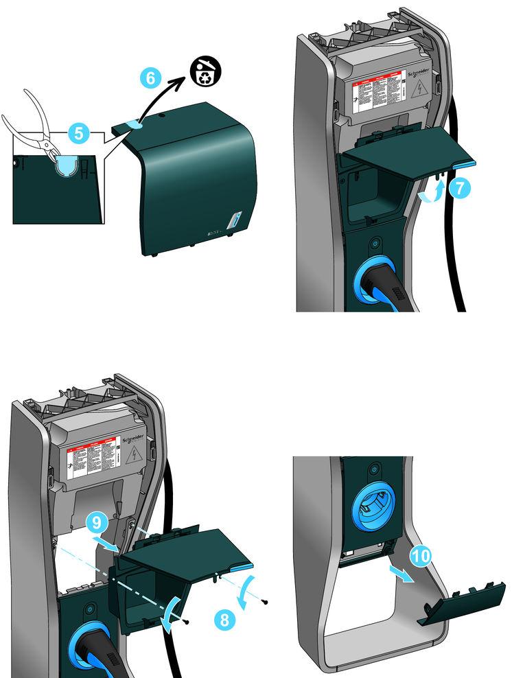
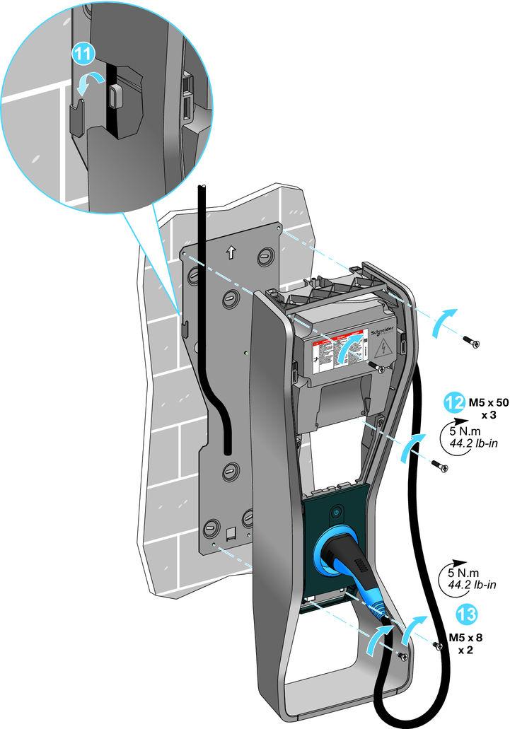
7 Preparation and mounting 7

8 The fixing screws must be supplied by the installer and selected according to the charging station weight and the wall type. 8
9 9
10 10
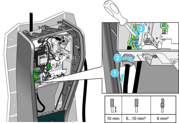
11 Wiring DANGER HAZARD OF ELECTRIC SHOCK, EXPLOSION, OR ARC FLASH The instalation must be protected by a circuit breaker and a Residual Current Device 30 ma Class A, installed in the switchboard. Systems that automatically reset the Residual Current Device are prohibited. An undervoltage remote tripping auxiliary associated with the circuit breaker can be added as an optional protection. Those electrical protections and the supply cable must be used only for the charging station and must be compliant with the electrical installation standard in force. Do not commission nor use the charging station if the measured earthing resistance is higher than the threshold specified by the local regulation in force. Failure to follow these instructions will result in death or serious injury. NOTICE DAMAGE TO CHARGING STATION Do not touch the electronic boards, use Electrostatic Discharge Devices before working inside the charging station.. A Surge Protection Device should be connected close to the charging station according to the Keraunic level of the installation area (*). The Surge Protection Device should be connected between the circuit breaker and the charging station, close to the charging station. Failure to follow these instructions can result in equipment damage. 11
12 Wiring diagram (TN-C earthing system forbiden, to be replaced by TN-C-S) Q1 : main circuit breaker Q2 : circuit breaker: rating 40 A (recommended) - C curve Residual Current Device: rating 30 ma A type (A Si type recommended) U : undervoltage remote tripping auxiliary (optional additional protection) F1 : surge protection device (*) type 2 Up = 1.5 kv (*) (*) For Russia, Australia and New-Zealand, the Surge Protection Device is mandatory. Derating option The charging station has a factory-set rated current of 20 A (rated power of 4.6 kw under 230 V). The electrical installation must be able to supply the required current. If the existing feeder in the switchboard or the supply cable is not compliant with the rated current, the feeder must be upgraded or the supply cable must be replaced. The factory setting can be modified to decrease the rated current if the electrical installation cannotsupply enough current or cannot be modified. However, this will increase the charging time! The rated current decrease must only be determined and performed by a trained electrician. Please contact the Wallbox Installation Service. 12
13 -L-N 13


14 Undervoltage remote tripping auxiliary (optional) 14

15 Type plate and safety label Remove the safety label and the warning label sheet and attach to the marked location. in the corresponding language from the supplied 15

16 Key locking system 16

17 Commissioning Ready for charging - Continuously illuminated Charging - Flashes Charging process halted via the Stop/Start button - Continuously illuminated Error - Flashes 17
18 Lighting behaviour of the LED indicator LED status Key locking system Vehicle connected or notconnected Wallbox Pure status Waiting for vehicle connection Charging halted by vehicle Waiting for the charging process Charging Charging halted by user Charging disabled Error 18
19 Charging the vehicle Starting the charging process Step Procedure Note 1 Turn the key to the "unlocked" position. 2 The LED indicator must be illuminated in solid blue. If not, please refer to the Troubleshooting section. Vehicle is unplugged. A solid blue light from the LED indicator means that the Wallbox Pure is waiting to begin charging. 3 Connect the charging cable to the charge point on the vehicle: The LED indicator is illuminated in solid blue if charging has not yet started. A vehicle timer can delay the start of charging. The vehicle performs an initialisation procedure: The indicator on the vehicle s charge point flashes orange. The vehicle indicates that it is not ready for charging in the following situations: The battery is already charged. 4 Charging starts as soon as the vehicle is ready for charging: The LED indicator then flashes blue. The battery temperature is too high. The vehicle s charging management system has interrupted the charging process. The vehicle starts the charging process: The indicator on the vehicle s charge point flashes blue. 19
20 Completing the charging process Step Procedure Note 1a Vehicle is connected and charging: The LED indicator flashes blue. The indicator on the vehicle's charge point flashes blue. 1b The LED indicator must be illuminated in solid blue. If not, please refer to the Troubleshooting section. Vehicle is connected and charging is complete: The LED indicator is illuminated in solid blue. 2a Ending the charging process: Press the Stop/Start button. The LED indicator is illuminated in solid green. If not, please refer to the Troubleshooting section. Pressing the Stop/Start button again restarts the charging process. The LED indicator flashes blue as soon as charging actually begins. The vehicle ends the charging process: The indicator on the vehicle's charge point is illuminated in white. 2b Charging halted by vehicle: The LED indicator is illuminated in solid blue. Possible reason: The vehicle interrupts the charging process because a timer was programmed: The indicator on the vehicle's charge point is illuminated in white Disconnect the charging cable from the vehicle: The LED indicator is illuminated in solid blue. If not, please refer to the Troubleshooting section. The vehicle interrupts the charging process because the battery is fully charged: The indicator on the vehicle's charge point flashes green. To release the plug lock: Open the vehicle using the remote control.
21 Troubleshooting DANGER HAZARD OF ELECTRIC SHOCK, EXPLOSION, OR ARC FLASH Repairs must only be performed by qualified personnel. Failure to follow these instructions will result in death or serious injury. 21
22 LED Status Cause Actions Electronics or contactor Trip the circuit breaker. Check the contactor connections. Reset the circuit breaker. If the error code persists, contact customer service. Trip the circuit breaker. Check the charging cable connections to the electronics. Reset the circuit breaker. If the error code persists, contact customer service. Trip the circuit breaker. Check the connections inside the Wallbox Pure. Reset the circuit breaker. If the error code persists, contact customer service. Trip the circuit breaker. Check the charging cable connections to the electronics. Reset the circuit breaker. If the error code persists, contact customer service. Trip the circuit breaker. Check the protective earth ground connection inside the Wallbox Pure (green and yellow cable). Reset the circuit breaker. If the error code persists, contact customer service. Cable connection Charging over-current Control circuit Car protective earth ground 22
23 Characteristics Technical data Reference standard: IEC Ed 2.0, IEC Ed 1.0, IEC Ed 2.0, IEC Ed 1.0. Power supply: 220 V V 1~. Output voltage: 0-30 V (pilot signal), 230 V AC (charging voltage), 32 A (charging current). Degree of protection IP54 for electrical parts in use, IP3X for housing parts. Operating temperature: -30 C to +50 C. Storage temperature: -40 C to +80 C. Application: Indoors or outdoors (with weather protection). Cable length: 4 m. Made in France. Declaration of Conformity The complete CE Declaration of Conformity (Low Voltage Directive LVD and Electromagnetic Compatibility Directive EMC) can be found on the following website of the manufacturer: 23
24 Mehr über BMW HRB Freude am Fahren 02/2014 (Z/Z) 1.0
BMW i. Freude am Fahren. Wallbox Pure
 BMW i Freude am Fahren Wallbox Pure 2 Wallbox Pure Owner's manual Imprint 5 Your Wallbox Pure advantages 6 Safety and warranty information 7 Operating elements and indicators 9 Charging the vehicle 12
BMW i. Freude am Fahren. BMW i Wallbox Plus. Instructions for use
 BMW i Freude am Fahren BMW i Wallbox Plus Instructions for use 5 EN BMW i Wallbox Plus Instructions for use BMW i Wallbox Plus Instructions for use INFORMATION Safety information Intended use About this
BMW i. Freude am Fahren. BMW i Wallbox Plus. Owner's manual
 BMW i Freude am Fahren BMW i Wallbox Plus Owner's manual BMW i Wallbox Plus Owner's manual 5 EN BMW i Wallbox Plus Owner's manual Contents INFORMATION 10 Safety information 10 Intended use 11 About this
BMW i. Freude am Fahren. BMW i Wallbox Plus. Instructions for use
 BMW i Freude am Fahren BMW i Wallbox Plus Instructions for use 5 EN BMW i Wallbox Plus Instructions for use BMW i Wallbox Plus Instructions for use INFORMATION Safety information Intended use About this
EVlink Parking EVF1 - EVW1
 EVlink Parking EVF1 - EVW1 Parking Charging Stations User Manual 07/2013 EVF1ppppppp EVW1ppppppp DOCA0063EN-01 www.schneider-electric.com This document contains general descriptions and/or general technical
BMW i Wallbox Connect
 BMW i Freude am Fahren BMW i Wallbox Connect Instructions for use 5 EN BMW i Wallbox Connect Instructions for use BMW i Wallbox Connect Instructions for use INFORMATION Safety information Intended use
INSTRUCTION & INSTALLATION
 INSTRUCTION & INSTALLATION MANUAL MODELS: CCL-eHOME T1C16 CCL-eHOME T1C32 CCL-eHOME T2C16 CCL-eHOME T2C32 WALLBOX ehome SERIES WALLBOX ehome Instruction and Installation manual This document is copyrighted,
c-go 24V/6A 24V/8A 24V/12A
 c-go 24V/6A 24V/8A 24V/12A Battery charger GB Instruction manual 1 Index 1. Product description... 2 2. Safety advices... 3 3. Quick start guide... 4 4. Operation... 4 5. Problem solving... 6 6. Specifications...
KeContact P20. User manual
 KeContact P20 User manual Comments to this manual In this manual you will find warnings against possible dangerous situations. The used symbols apply to the following meanings:!! WARNING! Indicates a potentially
ATS22D88Q soft starter-ats22-control 220V-power 230V (22kW)/ V(45kW)
/ V(45kW)") Product datasheet Characteristics ATS22D88Q soft starter-ats22-control 220V-power 230V (22kW)/400...440V(45kW) Complementary Assembly style Function available Supply voltage limits Main Range of product
Product datasheet Characteristics ATS22D88Q soft starter-ats22-control 220V-power 230V (22kW)/400...440V(45kW) Complementary Assembly style Function available Supply voltage limits Main Range of product
Sinewave Inverters. Jazz 700VA and 1000VA. User s manual
 Sinewave Inverters Jazz 700VA and 1000VA User s manual 1 Warranty RIPEnergy is not manufacturer of these units. All technical information s, data s and dimension s rely on information s given by the manufacturer.
DEVICE STATE/BYPASSED FAILURE OVERLOAD
 Technical specifications Type 5. 7. Control electronics Rated values Terminal Rated control supply voltage A1A2 V AC 115 230 115 230 Tolerance % -15+10-15+10 Rated control supply STANDBY ma 15 15 Rated
Sinewave Inverters. SWING 150VA and 300VA. User s manual
 Sinewave Inverters SWING 150VA and 300VA User s manual 1 Warranty RIPEnergy is not manufacturer of these units. All technical information s, data s and dimension s rely on information s given by the manufacturer.
HV-Angle Valve (Series 264) HV-InlineValve (Series 265) with electromagnetic actuator single acting with closing spring (NC)
 HV-InlineValve (Series 265) with electromagnetic actuator single acting with closing spring (NC)") HV-Angle Valve (Series 264) HV-InlineValve (Series 265) with electromagnetic actuator single acting with closing spring (NC) This manual is valid for the valve ordering number(s): 26... 26428 -K A 61 A..
HV-Angle Valve (Series 264) HV-InlineValve (Series 265) with electromagnetic actuator single acting with closing spring (NC) This manual is valid for the valve ordering number(s): 26... 26428 -K A 61 A..
MODVAR Low voltage reactive power compensation modules Installation manual
 MODVAR Low voltage reactive power compensation modules Installation manual MODVAR Low voltage reactive power compensation modules Before installation, read this manual carefully and keep at the disposal
Freedom egen System End-of- Line Functional Checklist
 U Freedom egen System End-of- Line Functional Checklist 976-0361-01-01 Rev A April 2018 DANGER RISK OF FIRE, ELECTRIC SHOCK, EXPLOSION, AND ARC FLASH This checklist is in addition to, and incorporates
Operating manual. High-voltage testing adapter VAS 6558A/30. Operating manual. Customer documentation Revision: 00 Version: 07/2018
 CAR-connect GmbH info@car-connect.cc www.car-connect.cc Page 1 of 12 Imprint Title: of high-voltage testing adapter Manufacturer: Copyright: CAR-connect GmbH Am Egelingsberg 8 D-38542 Leiferde Phone:+49
ZE motor-protective relay Overload monitoring of EEx e motors
 Building Automation Industrial Automation Systems Hardware and Engineering ZE motor-protective relay Overload monitoring of EEx e motors 0/0 AWB300-5GB A Think future. Switch to green. All brand and product
Altivar Regenerative Unit
 Altivar Regenerative Unit User Manual 11/2016 NVE88423-10/2016 www.schneider-electric.com The information provided in this documentation contains general descriptions and/or technical characteristics of
Quick Start Guide TS 910
 Quick Start Guide TS 910 DANGER HAZARD OF ELECTRICAL SHOCK, EXPLOSION, OR ARC FLASH Read and understand this quick start guide before installing and operating the transfer switch The installer is responsible
Operating instructions. FreeCon Contactless Power Contactless power transmission IE-CL240W-PP-BASE IE-CL240W-PP-REMOTE
 Operating instructions FreeCon Contactless Power Contactless power transmission IE-CL240W-PP-BASE 1547440000 IE-CL240W-PP-REMOTE 1547450000 Technical service: freecon.contactless@weidmueller.com Weidmüller
User s Manual. Automatic Switch-Mode Battery Charger
 User s Manual Automatic Switch-Mode Battery Charger IMPORTANT Read, understand, and follow these safety rules and operating instructions before using this battery charger. Only authorized and trained service
FLÄKTGROUP PM-MOTOR WITH INTEGRATED FC 106 FREQUENCY CONVERTER
 FLÄKTGROUP PM-MOTOR WITH INTEGRATED FC 106 FREQUENCY CONVERTER INSTALLATION AND MAINTENANCE INSTRUCTIONS Risk of electric shock: Motor terminals may still be live if the impeller is rotating, even when
Quick Start Guide TS 910 & TS 920
 Quick Start Guide TS 910 & TS 920 DANGER HAZARD OF ELECTRICAL SHOCK, EXPLOSION, OR ARC FLASH Read and understand this quick start guide before installing and operating the transfer switch The installer
Switching DC Power Supply
 99 Washington Street Melrose, MA 02176 Phone 781-665-1400 Toll Free 1-800-517-8431 Visit us at www.testequipmentdepot.com Model 1693, 1694 Switching DC Power Supply INSTRUCTION MANUAL 1 Safety Summary
Galaxy VM. Battery Breaker Box Installation 09/
 Galaxy VM Battery Breaker Box Installation 09/2016 www.schneider-electric.com Legal Information The Schneider Electric brand and any registered trademarks of Schneider Electric Industries SAS referred
INSTALLATION GUIDE AND USER MANUAL
 Electric Vehicle Charging Station INSTALLATION GUIDE AND USER MANUAL Model: 30A EVoCharge EVSE Model Number: EV072-300-001A Product Safety Certification: UL and cul Listed Description: SAE J1772 AC Level
Sinewave Inverters. SWING pro 200VA and 350VA. User s manual
 Sinewave Inverters SWING pro 200VA and 350VA User s manual 1 Warranty RIPEnergy is not manufacturer of these units. All technical information s, data s and dimension s rely on information s given by the
ACC Series Power Conditioner OPERATION & INSTALLATION MANUAL
 ACC Series Power Conditioner OPERATION & INSTALLATION MANUAL PHASETEC digital power conditioners are designed to safely operate electrical equipment in the harshest power quality environments. With a wide
Galaxy 300 Battery Breaker Kit G3HTBKIT1
 Installation 990 5739 001 03/2016 990 5739 001 Galaxy 300 Battery Breaker Kit G3HTBKIT1 What s in This Document Important Safety Instructions SAVE THESE INSTRUCTIONS...1 Safety Precautions...2 Specifications...4
XP600/1100/2000 INSTALLATION AND OPERATION MANUAL
 7317 Jack Newell Blvd North Fort Worth, Texas 76118-71 817-595-4969 voice, 817-595-129 fax 8-886-4683 toll free website wwwexeltechcom Manufacturer of UL Listed Products Copyright 21 Exeltech Inc All rights
READ AND SAVE THESE INSTRUCTIONS. Installation manual. DCC Charge controller for electric vehicle DCC-9, DCC-10. V2-6 Avril 2017.
 READ AND SAVE THESE INSTRUCTIONS Installation manual DCC Charge controller for electric vehicle DCC-9, DCC-10 Manufactured by Designed by V2-6 Avril 2017 Patent Pending Table of contents ABOUT THIS MANUAL
 www.ic-electronic.com Soft starter with integrated Motor Protection, Current and Voltage control Single phase controlled with internal by-pass ated operational Voltage 230VAC Frequency 45... 65Hz Self
1.1 Caution Statements
 USER MANUAL 1.1 Caution Statements Caution Statements cannot cover every potential cause of equipment damage but can highlight common causes of damage. It is the installer's responsibility to read and
Easy Start. 364 (3 ton) Soft Starter 368 (6 ton) Soft Starter. Installation Manual
 Soft Starter 368 (6 ton) Soft Starter. Installation Manual") Easy Start 364 (3 ton) Soft Starter 368 (6 ton) Soft Starter Installation Manual Micro Air Corporation Phone (609) 259-2636 124 Route 526. www.microair.net Allentown NJ 08501 Fax (609) 259-6601 Retrofit
Easy Start 364 (3 ton) Soft Starter 368 (6 ton) Soft Starter Installation Manual Micro Air Corporation Phone (609) 259-2636 124 Route 526. www.microair.net Allentown NJ 08501 Fax (609) 259-6601 Retrofit
Domestic Water Supply Pressure Pumps
 Domestic Water Supply Pressure Pumps Bianco Domestic Water Supply Pressure Pumps BIA-MULTI900PC BIA-MULTI1300 Instruction manual Safety precautions The symbol together with one of the following words Danger
User Manual. Solar Charge Controller 3KW
 User Manual Solar Charge Controller 3KW 1 CONTENTS 1 ABOUT THIS MANUAL... 3 1.1 Purpose... 3 1.2 Scope... 3 1.3 SAFETY INSTRUCTIONS... 3 2 INTRODUCTION... 4 2.1 Features... 4 2.2 Product Overview... 5
MCset kv Medium voltage equipment
 Maintenance Guide PE90014 PE90006 MCset 1-2 - 3 17.5 kv Medium voltage equipment Air-insulated switchboards Metal-enclosed switchgear with moving parts PE90007 PE90008 PE90009 PE90007 Maintenance Guide
Galaxy Receiving and Unpacking 09/
 Galaxy 5500 20 120 kva 400 V Receiving and Unpacking 09/2015 www.schneider-electric.com Legal Information The Schneider Electric brand and any registered trademarks of Schneider Electric Industries SAS
GHA. Gas-Insulated Switchgear. Gas-Insulated Switchgear. Switchgear extension and replacement of a panel
 Gas-Insulated Switchgear GHA Gas-Insulated Switchgear Switchgear extension and replacement of a panel During this work, essential parts of the switchgear remain in operation No. AGS 535 066-01 Edition
These devices meet the requirements of OSHA 29 CFR (b)(1)(ii) and OSHA 29 CFR (a) (2)(ii)(G). Airpax LEL series
(1)(ii) and OSHA 29 CFR (a) (2)(ii)(G). Airpax LEL series") PGFM Series GFCI Ground Fault Protection Sensing Module INTRODUCTION The LineGard PGFM GFCI Sensing Module is a ground fault or equipment leakage sensing device designed and manufactured by North Shore
PGFM Series GFCI Ground Fault Protection Sensing Module INTRODUCTION The LineGard PGFM GFCI Sensing Module is a ground fault or equipment leakage sensing device designed and manufactured by North Shore
INSTALLATION GUIDE AND USER MANUAL
 Electric Vehicle Charging Station INSTALLATION GUIDE AND USER MANUAL SAE J1772 AC Level 2 EVSE Model: 30A EVoCharge EVSE Wall Mount P/N: EV072-300-001A Version 2.0 IMPORTANT Read this manual thoroughly
VD4 Installation and service instructions kv A ka
 Medium voltage products VD4 Installation and service instructions 12... 36 kv - 630... 3150 A - 16... 50 ka Index For your safety! 1 I. Introduction 2 II. Programme for environmental protection 2 1. Packing
Safety technique. Emergency Stop Module BH 5928, BI 5928
 Safety technique Emergency Stop Module BH 5928, BI 5928 with time delay safemaster 0226419 Function diagram According to EU directive for machines 98/37/EG According to IEC/E 60 204, E 954-1 Safety category
HANGKAI GROUP HOYMILES MICRO-INVERTER MI-250
 HANGKAI GROUP HOYMILES MICRO-INVERTER MI-250 TECHNICAL MANUAL CONTENTS INTRODUCTION... 3 SAFETY... 4 SYMBOL ILLUSTRATION... 4 INSTALLATION WARNINGS... 6 PREPARE FOR INSTALLING... 7 TRANSPORT AND INSPECT...
Battery Charger. Series EASY Charger. User s manual
 Battery Charger Series EASY Charger User s manual 1 Warranty RIPEnergy is not manufacturer of these units. All technical information s, data s and dimensions rely on information s given by the manufacturer.
Wilo-Control SC-Fire Jockey
 Pioneering for You Wilo-Control SC-Fire Jockey de en fr Einbau- und Betriebsanleitung Installation and operating instructions Notice de montage et de mise en service nl Inbouw- en bedieningsvoorschriften
Thyristor power controller TE10A. Burst-firing Single-cycle Advanced Single-cycle
 Thyristor power controller TE10A Burst-firing Single-cycle Advanced Single-cycle Control of short-wave infrared elements and loads of constant resistance up to 20kW User Manual Copyright Eurotherm Automation
Ultra Sine Inverter (US) Generation 4 (G4) User Guide
 Generation 4 (G4) User Guide") IBS Intelligent Battery System GmbH Seestrasse 24, CH-3600 Thun, Schweiz Tel: +41 33 221 06 16 Fax: +41 33 221 06 17 E-Mail: info@ibs-tech.ch Ultra Sine Inverter (US) Generation 4 (G4) User Guide IBS-USG4_en_v2.0.3.doc
IBS Intelligent Battery System GmbH Seestrasse 24, CH-3600 Thun, Schweiz Tel: +41 33 221 06 16 Fax: +41 33 221 06 17 E-Mail: info@ibs-tech.ch Ultra Sine Inverter (US) Generation 4 (G4) User Guide IBS-USG4_en_v2.0.3.doc
Oil-free piston compressors KK and piston vacuum pumps KV
 Oil-free piston compressors KK and piston vacuum pumps KV Installation and Operating Instructions 0678106030L02 1707V003 Contents Important information 1 About this document 2 1.1 Warnings and symbols
Operating instructions. sonnenprotect for operators. KD-337 Part no Version X00.
 Operating instructions for operators sonnenprotect 1300 KD-337 Part no. 22010 Version X00 info@sonnenbatterie.de www.sonnenbatterie.de EN IMPORTANT Read this documentation carefully before operation. Retain
VADA - V60-J PRODUCT OVERVIEW CONSTRUCTION MOTOR USAGE LIMITATIONS WARRANTY
 PRODUCT OVERVIEW The VADA series of self priming jet pumps combine the functional benefits of centrifugal pumps and the practical and qualitative benefits of self-priming pumps. The Venturi system the
Operating instructions
 Operating instructions Digital tank contents indicator DTA 10 DTA 10 DTA 10 0 4.0 m fuel oil 0 3.5 m water Read instructions before using device! Observe all safety information! Keep instructions for future
HIB Enclosed Inverter User Guide
 HIB Enclosed Inverter User Guide (0.75kW~22kW) V1.2.0 Contents 1 Safety information...1 2 Technical Data...2 3 Motor Connection...4 4 Operation...5 5 Single phase circuit diagram...7 6 Three phase circuit
Accessories for power generation plants in Italy SMA GRID GATE
 Accessories for power generation plants in Italy SMA GRID GATE Installation Manual GridGate-11-IA-en-12 Version 1.2 EN SMA Solar Technology AG Table of Contents Table of Contents 1 Information on this
BODAS Pressure sensor PR3 series 10
 BODAS Pressure sensor PR3 series 10 RE 95155 Edition: 04.2014 Replaces: 12.2013 Measurement ranges to 25, 50, 160, 200, 250, 400, 600 bar Ratiometric output signal 0.5 to 4.5 V with 5 V supply voltage
Product Overview. Product Identification. Amps One CT Two CTs Three CTs
 AH06 (optional mounting bracket for small, medium, and large CTs) DANGER HAZARD OF ELECTRIC SHOCK, EXPLOSION, OR ARC FLASH Follow safe electrical work practices. See NFPA 70E in the USA, or applicable
SOLAR LIGHTING CONTROLLER SUNLIGHT MODELS INCLUDED IN THIS MANUAL SL-10 SL-10-24V SL-20 SL-20-24V
 SOLAR LIGHTING CONTROLLER OPERATOR S MANUAL SUNLIGHT MODELS INCLUDED IN THIS MANUAL SL-10 SL-10-24V SL-20 SL-20-24V 10A / 12V 10A / 24V 20A / 12V 20A / 24V 1098 Washington Crossing Road Washington Crossing,
Operations Manual Pika Harbor Smart Battery
 Operations Manual Pika Harbor Smart Battery Harbor Flex / Harbor Plus Part of the Pika Energy Island M00017-02 Harbor Smart Battery Serial Number: RCP Number: We are committed to quality and constant improvement.
Galaxy VX Battery Breaker Trip Board (GVXBBTB) and Battery Breaker Capacitor Board (GVXBBCB)
 and Battery Breaker Capacitor Board (GVXBBCB)") Installation 990 91076 001 12/2017 Galaxy VX Battery Breaker Trip Board (GVXBBTB) and The battery breaker trip board is the interface from the battery bank to the UPS battery auxiliary inputs/outputs and
Installation 990 91076 001 12/2017 Galaxy VX Battery Breaker Trip Board (GVXBBTB) and The battery breaker trip board is the interface from the battery bank to the UPS battery auxiliary inputs/outputs and
DIAGNOSTIC POWER SUPPLY WSC 720. user guide. 12 V/24 V lead acid batteries ah
 DIAGNOSTIC POWER SUPPLY WSC 720 user guide 12 V/24 V lead acid batteries 40-500 ah gb 1 Thank you for choosing this charger from Exide Technologies Your WSC720 is a quality product from Exide Technologies.
Operating Instructions for PAC800 Battery Charger
 Operating Instructions for PAC800 Battery Charger General Safety The charger may only be used for the specified battery types. This battery charger is supplied with pre-set charging curves that are adapted
WOOOM INSTRUCTION MANUAL
 WOOOM INSTRUCTION MANUAL Thank you very much for choosing the Wooom chair from Klöber! Please read this instruction manual carefully before using the chair. Please download the Wooom app to your device
Smart 110 with built-in flashlight for 6 240Ah lead-acid batteries
 USER GUIDE Battery Charger Smart 110 with built-in flashlight for 6 240Ah lead-acid batteries Please read this user guide carefully before using the charger Use protective eyewear when handling batteries
RE-PR3-E-86&105 3-Phase Panel Mount 86 and 105kW
 Page 1 of 6 3-Phase Panel Mount 86 and 105kW Features: Benefits: 0-10Vdc, 0-5Vdc, 4-20mA or manual via potentiometer control input Over temperature protection with auto reset Enclosed panel mounting Efficient
ALIEM USER MANUAL R. Bocconi. REV. DATE Checked and Approved R. T.
 ALIEM USER MANUAL 2 19-04-2018 R. Bocconi REV. DATE Checked and Approved R. T. PAGE INTENTIONALLY LEFT BLANK 2 ALIEM 1000 USER'S MANUAL Version 2 dated 19-04-2018 1 INTRODUCTION ALIEM 1000 is an emergency
Maintenance Bypass Switch
 Part. LE09522AA-08/16-01 GF 3 109 53 Maintenance Bypass Switch Installation Manual 3 109 53 Maintenance Bypass Switch EN FR ENGLISH 3 2 3 109 53 Maintenance Bypass Switch Index 1 Introduction 4 1.1 Overview
Operating instructions and spare parts list. LM01 Level sensor. Translation of the original operating instructions
 En Operating instructions and spare parts list LM01 Level sensor Translation of the original operating instructions Documentation LM01 Level sensor Copyright 2005 Gema Switzerland GmbH All rights reserved.
Battery Charger Series EASY Charger
 Battery Charger Series EASY Charger User s manual 1 Warranty RIPEnergy is not manufacturer of these units. All technical information s, data s and dimensions rely on information s given by the manufacturer.
Accessories for Wind Power Inverter WINDY BOY PROTECTION BOX 400 / 500 / 600
 Accessories for Wind Power Inverter WINDY BOY PROTECTION BOX 400 / 500 / 600 Installation Guide WBP-Box-IEN103320 IMEN-WBP-BOX Version 2.0 EN SMA Solar Technology AG Table of Contents Table of Contents
XMLRM01G1P25 Pressure sensors XMLR -1 bar - G 1/4-24VDC ma - PNP - M12
 Characteristics Pressure sensors XMLR -1 bar - G 1/4-24VDC - 4..20 ma - PNP - M12 Complementary Current consumption Electrical connection Type of output signal Analogue output function Discrete output
Operator Manual. Transfer Switch. RSS100 and RSS Cummins Inc. All rights reserved. English
 Operator Manual Transfer Switch RSS100 and RSS200 English 8-2007 962 0134 Table of Contents SECTION TITLE PAGE SAFETY PRECAUTIONS................................................... ii 1. INTRODUCTION.........................................................
Drive Unit e-drive1. Installation instructions 04/2014. English translation of the original German installation instructions
 Drive Unit e-drive1 Installation instructions 04/2014 English translation of the original German installation instructions Contents Foreword... 3 Availability... 3 Structural features in the text... 3
User Manual Solar Charge Controller 3KW
 User Manual Solar Charge Controller 3KW Version: 1.3 CONTENTS 1 ABOUT THIS MANUAL... 1 1.1 Purpose... 1 1.2 Scope... 1 1.3 SAFETY INSTRUCTIONS... 1 2 INTRODUCTION... 2 2.1 Features... 2 2.2 Product Overview...
Bosch Smart Home. Door/Window Contact Instruction Manual
 Bosch Smart Home Door/Window Contact Instruction Manual Start making your home smart! Please be sure to install the Bosch Smart Home Controller first. Please ensure that you have a Bosch Smart Home Controller
Model C230 Pump Controller
 MANUAL Model C230 Earthsafe Systems, Inc. 7553 S. Madison Willowbrook, IL 60527 T: (630) 794-5100 F: (630) 794-5106 info@earthsafe.com www.earthsafe.com March 1, 2010 The information contained herein is
Power thyristor units. 460 series. Control of single-phase resistive and inductive loads. User Manual
 Power thyristor units 460 series Control of single-phase resistive and inductive loads User Manual Copyright Eurotherm Automation 1996 All rights reserved. All reproduction or transmission in any form
Sinewave Inverter. HIPHOP pro 1500 HIPHOP pro User s manual
 Sinewave Inverter HIPHOP pro 1500 HIPHOP pro 2000 User s manual 1 Warranty RIPEnergy is not manufacturer of these units. All technical information s, data s and dimension s rely on information s given
Three-Phase Soft Starters
 Submittal Data English Language/IP Units 04/14 Contact Information: Hyper Engineering, Pty. Ltd. 4 / 14 Ralph Black Dr Wollongong Nth, NSW 2500 AUSTRALIA www.hypereng.com sales@hypereng.com (+61) 2 4229
Installation manual wall-mounted distributor
 EN Installation manual wall-mounted distributor EN 60003233 Issue 11.2016 2016-14-11 Table of contents 1 About this manual 3 1.1 Structure of the warnings 3 1.2 Symbols used 4 1.3 Signal words used 4 2
CALTRAP INSTALLATION AND OPERATIONS MANUAL
 INSTALLATION AND OPERATIONS MANUAL NOTE Please read this entire installation and operations manual before energizing the. Safety Considerations: Installing and servicing capacitor equipment can be hazardous.
Installation Instructions Electric Heaters 5 20 kw
 Small Packaged Products 2 to 5 Tons Accessory Electric Heaters Cancels: IIK 564A-24-2 IIK 564A-24- -02 Installation Instructions Electric Heaters 5 20 kw NOTE: Read the entire instruction manual before
Rental Industry Safety Tester Safe Check 5s
 Rental Industry Safety Tester Safe Check 5s Feb 2006 2006 Clare Instruments Inc. Issue 2.0 Firmware Version : 1.2a Limited Warranty & Limitation of Liability Clare Instruments Inc, guarantees this product
Installation Guide Smart-UPS On-Line SRT1000/1500 UXI-NCLI, SRT1000/1500 UXI-LI, Tower/Rack-Mount
 Installation Guide Smart-UPS On-Line SRT1000/1500 UXI-NCLI, SRT1000/1500 UXI-LI, Tower/Rack-Mount Important Safety Messages Read the instructions carefully to become familiar with the equipment before
Electric vehicle charging system
 TECHNICAL REFERENCE (ICS 43.120) TECHNICAL REFERENCE FOR Electric vehicle charging system Published by SPRING Singapore 2 Bukit Merah Central Singapore 159835 SPRING Singapore Website: www.spring.gov.sg
Installation manual portable distributors
 EN Installation manual portable distributors EN 60003206 Issue 11.2016 15/11/2016 Table of contents 1 About this manual 3 1.1 Structure of the warnings 3 1.2 Symbols used 4 1.3 Signal words used 4 2 Intended
Instruction manual. Type 3AH35-MA vacuum circuit breaker magnetic-actuator operator module.
 Instruction manual Type 3AH35-MA vacuum circuit breaker magnetic-actuator operator module Installation operation maintenance E50001-F710-K378-V6-4A00 www.usa.siemens.com/sdv7 Hazardous voltages and stored
MULTI FUNCTION POWER PAK PLUS
 MULTI FUNCTION JUMP START UP TO V8 PETROL & DIESEL 600A PEAK CURRENT RECHARGE USB POWER TOOLS TABLETS LAPTOPS MOBILE PHONES RECHARGE DEVICES ON-SITE VEHICLE JUMP STARTER KP1404 ED2 (June 15) Table of Contents
SubDrive Inline Constant pressure controller Additional information for Australia, NZ TOLL FREE HELP 1300 FRANKLIN
 SubDrive Inline 1100 Constant pressure controller Additional information for Australia, NZ 1 TOLL FREE HELP 1300 FRANKLIN ! WARNING Serious or fatal electrical shock may result from failure to connect
QF(26) - Series Miniature Circuit Breakers - Low Rating (5-63 A)
 - Series Miniature Circuit Breakers - Low Rating (5-63 A)") QF(26) - Series Miniature Circuit Breakers - Low Rating (5-63 A) Dual Mount 1 pole Dual Mount 2 pole Dual Mount 3 + N Features AC circuit breaker Hydraulic-magnetic technology % rating capability, independent
QF(26) - Series Miniature Circuit Breakers - Low Rating (5-63 A) Dual Mount 1 pole Dual Mount 2 pole Dual Mount 3 + N Features AC circuit breaker Hydraulic-magnetic technology % rating capability, independent
Single & Three-Phase Soft Starters
 Submittal Data English Language/IP Units 11/13 Contact Information: Hyper Engineering, Pty. Ltd. 9000 Conservation Way Fort Wayne, IN 46809 www.hypereng.com sales@hypereng.com (877) 304-0724 Model Nomenclature
c-go 12V/10A 12V/20A Power supply and battery charger Instruction manual
 c-go 12V/10A 12V/20A Power supply and battery charger GB Instruction manual 1 Index 1. Product description... 2 2. Safety advices... 3 3. Mounting and installation... 4 4. Operation... 5 5. Problem solving...
POWER SUPPLY UNIT FOR 3 KW MAGNETRON TECHNICAL NOTE
 POWER SUPPLY UNIT FOR 3 KW MAGNETRON TECHNICAL NOTE (Issue April 2004) CE Declaration of Conformity Dichiarazione di Conformità CE Manufacturer s Name: Nome del Costruttore: Manufacturer s Address: Indirizzo
Inverter / Charger Accessory for Steca Solarix PLI Phase / Parallel Kit. Installation and operating instructions Z01 17.
 Inverter / Charger Accessory for Steca Solarix PLI 5000-48 3-Phase / Parallel Kit Installation and operating instructions GB Z01 17.31 Table of Contents About this Manual... 2 Purpose... 2 Scope... 2 Keywords
GENERAL INFORMATION. INSTRUCTIONS FOR 500A Lithium Jump Starter
 INSTRUCTIONS FOR 500A Lithium Jump Starter Stock No.15067 Part No.LJS136 IMPORTANT: PLEASE READ THESE INSTRUCTIONS CAREFULLY TO ENSURE THE SAFE AND EFFECTIVE USE OF THIS PRODUCT. GENERAL INFORMATION These
Installation Instructions Electric Heaters 5 20 kw
 Small Packaged Products to 5 Tons Accessory Electric Heaters Cancels: IIK 564A--1 IIK 564A-- 11-01 Installation Instructions Electric Heaters 5 0 kw NOTE: Read the entire instruction manual before starting
Language specific user manuals are available on
 User Manual WEB Charger for LiFePO 4 Batteries EN User Manual Language specific user manuals are available on www.mascot.no/downloads/usermanuals Bruksanvisning Käyttöohjeet Bedienungsanleitung Mode d
Installation Instructions
 NOTE: Read the entire instruction manual before starting the installation. This symbol indicates a change since the last issue. SAFETY CONSIDERATIONS Installing and servicing air conditioning equipment
Table of Contents 文管中心 發行章
 ST600-XXX Series Pure Sine Wave Power Inverter User s Manual Table of Contents 1. Important Safety Instructions 1-1 General Safety Precautions 1 1-2 Battery Precautions. 1 2. Basic Descriptions 2-1 Mechanical
KD LV Motor Protection Relay
 1. Protection Features KD LV Motor Protection Relay Overload (for both cyclic and sustained overload conditions) Locked rotor by vectorial stall Running stall / jam Single phasing / Unbalance Earth leakage