dx 3 protection that meets your requirements GloBal SpecialiSt IN electrical AND DIgITAl BUIlDINg INFrASTrUCTUreS catalogue pages inside
|
|
|
- Francis Lane
- 6 years ago
- Views:
Transcription


1 dx 3 protection that meets your requirements catalogue pages inside GloBal SpecialiSt IN electrical AND DIgITAl BUIlDINg INFrASTrUCTUreS


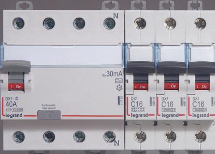
2 the new dx 3 legrand offer offers you leading-edge technical features with its new DX 3 range of modular circuit breakers. This range, up to 125 A, is suitable for all residential, commercial and industrial applications which require high performance, selectivity and back-up combination of devices. In this document, discover the innovations of this new range which will enable you to build more reliable, higher performance and more economical distribution boards. protection/breaking 2-3 A clear, comprehensive offer for all types of application 4-5 Performance that meets your requirements 6-7 Clear identification of each circuit


3 control 8-9 Impeccable quality easy, safe connection More comfortable buildings and energy savings measurement Protection tailored to your requirements Choose your distribution Measurement at the heart of energy efficiency Perfect control of your installation easy operation and maintenance Catalogue pages DX 3 New modular protection 1

4 Legrand, a clear, comprehensive offer for all types of application The new DX³ circuit breakers can be integrated in a wide range of products, providing exceptional technical and economic performance levels The variety of functions and range of characteristics offered will enable you to equip all your distribution boards. The very high levels of coordination between the various ranges of DX³ modular circuit breakers or between DX³ modular circuit breakers and DPX³ MCCBs enable the cost of the installation to be optimised. Measurement Protection/Breaking control All functions on DIN rail 2


5 Each breaking capacity has its own power solution Perfect complementarity for your distribution boards up to A and 100 ka breaking capacity. DX 3 DPX 3 DPX DMX 3 In ka ka 25 ka 36 ka 50 ka 65/75 ka 100 ka DMX 3 DMX 3 DMX DPX DPX DPX DPX DPX3 DPX 3 DPX 3 DPX 3 DPX 3 63 DX 3 DX DX 3 DX 3 DX 3 DX 3 New modular protection 3


6 performance that meets your requirements The DX 3 range is designed to meet the efficiency, safety and compliance requirements with which new electrical installations must comply. Nominal current, breaking capacity, number of poles, tripping curve, discrimination: the electrical characteristics of the new DX³ circuit breakers have been designed to meet the needs of all types of installations, from residential buildings to the largest industrial sites, including commercial buildings of all sizes. Compact: 10 to 32 A 4-pole DX³ rcbo only 4 modules, protected neutral. 4


7 DX 3 performance A comprehensive, uniform range up to 125 A nominal current and 50 ka breaking capacity in a compact unit (1 or 1.5 modules/pole). Breaking capacity Curve B ka C D ka B C D 25 ka 36 ka 50 ka C D C C D DX³ circuit breakers are limitation class 3 : they limit the shortcircuit power in the cables and can prolong the installation s life by avoiding damage to the cables resulting from the stresses caused by the power flowing through them. The products never work at the limit of their capacity The information in the table applies to 1P, 3P and 4P circuit breakers. For further information on the number of modules per pole, please refer to the catalogue pages. 1 module per pole 1.5 module per pole THe Xl Pro CAlCUl AND Xl Pro 3 software include the whole DX 3 range for building perfect distribution boards. 125 A Main distribution board Secondary board 40 A The tripping characteristics are calculated and adjusted to ensure correct discrimination between the different protection levels in order to improve ease of use. CoNTINUITY of SerVICe: optimum DISCrIMINATIoN The excellent discrimination between DX³ circuit breakers and with DPX or DPX³ MCCBs ensures optimum continuity of service for your installations. DX 3 protection/breaking 5


8 clear identification of each circuit At the head of distribution boards, at the head of rows or to protect outgoing lines up to 125 A. There is always a DX 3 solution Quick identification of devices and circuits is a guarantee of efficiency not only for installation but also for operation and maintenance. legrand has always taken great care with the marking and ease of identification of its circuit breakers. The DX³ range includes new enhancements so that your distribution boards are even easier to use. 6


9 Technical labelling area Innovative labelholder: Improved opening Enhanced dust protection Label remains firmly in place during transport Identification Dual identification of the breaking capacity and clear marking for easier maintenance Black handle: circuit breakers grey handle: switches Breaking capacity 16 ka 25 ka 36 ka 50 ka Curve limitation class 3 (on concerned ratings and breaking capacities) rating Breaking capacity according to IeC STATe of THe CIrCUIT BreAKer Can be identified quickly via the colour marking on the handle: I-on/red o-off/green DX 3 protection/breaking 7


10 dx 3 impeccable QuaLity legrand pays particular attention to how these devices perform: each of them is set and checked individually on the production lines Isolating switches, rcds, circuit breakers, rcbos, add-on modules, control and signalling auxiliaries: the guarantee of finding the function you need with a uniform appearance and optimised dimensions. CerTIFICATIoN of legrand S FACTorIeS: ISo 9001 for quality ISo for environmental protection 8

.")
 (see page 12).")

11 DX³ ProDUCTS Are CerTIFIeD IN ACCorDANCe with INTerNATIoNAl ProDUCT STANDArDS. Approvals, such as VDe, which are universally recognised for the rigour of their requirements, are renewed annually. All DX 3 circuit breakers can be used with an add-on module (see page 10). The DX 3 control and signalling auxiliaries are common to all the protection devices irrespective of their size (1 or 1.5 modules per pole) (see page 12). CoPYTrACer, THe FIgHT AgAINST CoUNTerFeITINg Copytracer is a unique registration number that is marked on some of our products. The number is stored in a database. go to the website: DX 3 protection/breaking 9


12 protection tailored to your requirements with the DX 3 add-on modules The new DX³ add-on modules have a wide range of features to meet the most stringent requirements for the protection of people. like the new DX³ circuit breakers, they offer high performance levels and incorporate innovative solutions for installation and operation. Tripping on residual current faults is signalled by a yellow indicator 125 A add-on modules have automatic connection tap-off terminals for auxiliary circuits Sealable terminal shield included on the whole range High-capacity terminals and integrated insulating shields Version FIXeD ADJUSTABle Sensitivity 30 ma 300 ma ma Time delay Instantaneous Instantaneous ms Max. current 63 A 125 A 63 A 125 A 63 A 125 A AC type A type Hpi 4P 2P 3P 4P A single mounting principle for all DX³ add-on modules It has never been so quick and safe to fit an add-on module. The exclusive legrand system, common to the whole DX³ range, makes the assembly extremely strong and provides guaranteed safety. 10


13 DX 3 25kA T t 0,5A DX 3 25kA 30mA -25 0,3A 60ms T 1 n=1a 1 =1A 0 t 0,5A 150ms DX 3 30mA -25 0,3A 60ms T 1 =1A 1 n=1a 0 t 0,5A 150ms Maximum continuity of service DX³ adjustable add-on modules can provide discrimination up to 3 levels by adjusting their sensitivity. They enable those parts of the installation that are not affected by a fault to remain operational, while ensuring total safety of people. 4P A ADD-oN MoDUle adjustable version easy to access settings on the front panel with sealable transparent cover 0,3A 0,5A 1 n=1a 1A 30mA 60ms 150ms 0 t Ma63 Ma63 Ma63 FIT THe CIrCUIT BreAKer and the add-on module lock THe CoMBINATIoN TogeTHer TIgHTeN THe TerMINAlS and fit the terminal shield DX 3 protection/breaking 11
14 Perfect control of your installation The DX³ range has a selection of electrical auxiliaries for monitoring and controlling circuits remotely Auxiliary contacts and fault signal contacts, shunt trips, undervoltage releases, motorised controls and automatic reclosers 12


 The")


 just as easily as auxiliaries.")


15 THe AUXIlIArIeS FIT FIrMlY without the need for any tools and ensure the whole assembly is robust THe ACCeSSIBIlITY of THe TerMINAlS and the visibility of the screw heads make the installer s work easier Marking of auxiliaries (characteristics, connection, mounting) The fault signal contacts have a test button The colour code of the indicators on the signalling auxiliaries is the same as that of the remote indicators DX³ circuit breakers take up to 3 auxiliaries including one control auxiliary DX³ motorised controls can be used with 1 module per pole devices (circuit breakers, rcbos and rccbs) just as easily as auxiliaries. optimised SPACe IN THe DISTrIBUTIoN BoArD legrand motorised controls are the most compact on the market: 1 module wide. They save a great deal of space inside the distribution board. DX 3 protection/breaking 13
16 easy, safe connection Safety is prioritised with the innovative features of the DX 3 products The quality and hold of the connections are vital for the safety of distribution boards. This is why legrand, with its wealth of experience and expertise, has broken new ground again with terminals with a loosening compensation system and retractable insulating shields. 1 MoDUle/Pole Terminal capacity : In 63 A 35 mm² 1,5 MoDUleS/Pole Terminal capacity : In 63 A 50 mm² In 80 A 70 mm² 14


")


17 wire guide FlAP ensures the wire is in the correct position rising ClAMP TerMINAlS ensure a high quality, durable connection reliable CoNNeCTIoNS Compensation for the effect of loosening to ensure excellent hold over time and consistent contact (In 80 A) Temperature rise -20% 1 module/pole 1,5 modules/pole Clamping screw for flat or pozidrive screwdriver. Tightening torques higher than those recommended by the standard The use of an Allen key makes it easier to tighten to the required torque (In 80 A) retractable INSUlATINg SHIelDS with the integrated retractable insulating shields, no additional accessories are needed to isolate the connections on all breaking capacities and high ratings of the 1.5 modules/pole (In 63 A) circuit breakers. DX 3 protection/breaking 15


18 choose your distribution A wide range of distribution devices is available for your modular rows From the simple supply busbar to the HX³ 125 A plug-in distribution block, whether they have conventional screw connections or more innovative automatic terminal connections, or plug in directly, Legrand quality is always there. STANDARD DISTRIBUTION Supply busbars DX³ 1 module/pole devices up to 63 A can be connected to supply busbars via the top or the bottom. STANDARD DISTRIBUTION Modular distribution blocks The 40 to 250 A modular distribution blocks are totally universal, making them suitable for all types of distribution board. Four-pole distribution For three-phase horizontal distribution in a single action. to the other rows 16


19 OPTIMISED DISTRIBUTION VX 3 63 and 125 A, vertical distribution blocks with automatic terminals - Significant space saving due to their vertical installation beside the rows - Time saving as there is less wiring with the IP 2x automatic terminals for flexible or rigid wires. Mounting in Legrand enclosures: Plexo³, XL³125, 160, 3 to 6 rows SUPPLY BUSBARS, AN IDEAL ADDITION In addition to 4-pole vertical distribution blocks with automatic terminals, supply busbars power the devices in each row via the head of row protection device. DX 3 PROTECTION/BREAKING 17


20 choose your distribution (continued) Legrand optimised distribution has been designed for maximum safety and for ease of installation and maintenance of distribution boards Wiring and tedious tightening operations are minimised, and the risks of poor contact and short-circuits are reduced while mounting time is optimised. OPTIMISED DISTRIBUTION HX A horizontal distribution blocks with automatic terminals Horizontal 4-pole distribution for XL³ 160 to 4000 enclosures: - Freedom to mix 1P, 1P+N, 2P, 3P and 4P devices on the same row - Space saving: installed between the rows - Time saving: less wiring, IP 2x automatic terminals for flexible or rigid wires Fixing lugs for mounting on rails. Mounting also possible on solid plate 18


.")

21 DISTRIBUTION BLOCK SUPPLY VIA THE POWER SUPPLY MODULE PROVIDED 2 1 CONNECTION MODULES Set of 4 connection modules (L1, L2, L3, N) for 1 module/pole devices OPTIMISED DISTRIBUTION HX A horizontal distribution blocks with plug-in connection Horizontal 4-pole distribution for XL³ 160 to 4000 enclosures: - Optimised design: freedom to mix 1P, 1P+N, 2P, 3P and 4P devices on the same row - Optimised installation: automatic connection with no wiring or clamping - Safe connection and disconnection of devices, even when the distribution block is powered-up (due to the IP xxb insulation of the distribution block and the integral connection modules in the devices). DISTRIBUTION BLOCK SUPPLY VIA THE MAIN DEVICE EASY CONNECTION Circuit breakers with plug-in terminals are fixed onto the distribution block with no need for any tool. The phase to be connected is determined by the choice of connector. The distribution block can be supplied via the power supply module provided or via the head of row device. DX 3 PROTECTION/BREAKING 19
22 easy operation and maintenance When designing the DX³ range, Legrand did not forget about users and maintenance engineers As well as the already wellknown functions such as the double clip which enables maintenance to be carried out on the module, new features such as the labelling area, automatic connection tap-off terminals and status indicators have been added to make day-to-day use of distribution boards even easier. 20


23 EASY TAP-OFF CONNECTION FROM 80 A The IP 2x automatic tap-off terminals can be used to connect an auxiliary circuit or a measuring device safely INCREASED SAFETY The DX³ range guarantees IP2x protection. There is no risk of contact with live parts, even when the faceplate is open. LOCKING IN OPEN POSITION for 1.5 module per pole devices using a single Colring cable tie THE DOUBLE CLIP enables a device to be replaced without disconnecting the whole row DX 3 PROTECTION/BREAKING 21
24 More comfortable buildings and energy Savings The Legrand modular control and monitoring devices are a perfect addition to the range of DX³ protection devices With the same design, they integrate perfectly in your distribution boards. Power contactors, pulse operated latching relays, pushbuttons, indicators, timers, programmers, etc. With the selection of functions available it is simple to improve the safety, efficiency and comfort of installations and meet energy requirements. 22


25 SUPPLY BUSBAR INSERTION There is a position on the top of the control devices for inserting the supply busbar LIGHT SENSITIVE SWITCH to switch lighting on automatically when the natural light decreases 16 A TO 63 A LEGRAND POWER CONTACTORS are available with 24 VAC or 230 VAC coil TIMER to switch off of lighting automatically after an adjustable period of 0.5 s to 10 min - 1 to 4 x 16 A outputs - 24-hour, 7-day or annual programming - Programming direct or from a PC with a transfer key ENERGY SAVINGS WITH TIMERS In order to optimise power consumption, Legrand electronic timers can be used to assign operating periods, for example for heating or lighting. DX 3 CONTROL 23


26 measurement at the Heart of energy efficiency A project to optimise quality and energy efficiency must include measurement Measurement upstream, to identify the critical points and ensure optimum targeting of the actions to be taken. Downstream to monitor the effects and control any drift. Legrand EMDX³ measurement control units and electricity meters will naturally have a place in distribution boards. EMDX 3 measurement control units All the essential parameters of the installation on DIN rail or on the door : - Dual tariff metering - Active and reactive energy - Operating time - Power factor - Harmonic distortion - Programmable alarms EMDX³ UNIT ON DIN RAIL EMDX³ UNIT ON DOOR EMDX³ units on doors provide a large size display and their capacity can be increased with extension modules. 24


 sheets.")
, supervision")


27 ECO-DESIGN A VOLUNTARY APPROACH The Legrand group has been taking environmental problems into account since This approach is based on international standards for the objective measurement of the environmental impacts of products in terms of both consumption of resources and pollution. Legrand publishes these reports in the form of PEP (Product Environmental Profile) sheets. Remote supervision and viewing With the Legrand communication interfaces (RS 485, IP), supervision software and Web servers, measurements can be centralised and displayed remotely on a PC, tablet or smartphone. EMDX 3 electricity meter on DIN rail EMDX³ meters installed in secondary distribution boards can be used to monitor consumption per building, per floor and per application. DISPLAY OF 32 MEASUREMENT POINTS ON TABLET COMPUTERS AND WEB SERVERS DX 3 MEASUREMENT 25


28 RCDs and RCBOs P. 28 DX³-ID 2-pole RCDs from 16 to 100 A MCBs P. 32 DX³ ka MCBs from 1 to 63 A Add-on modules P. 38 DX³ 2-pole add-on modules for 1 module/pole MCBs Auxiliaires, remote control and accessories P. 40 Signalling auxiliaires Other control functions P. 49 CX 3 power contactors DIN RAIL equipment EMDX³ electrical energy meters & measuring units P. 58 EMDX³ electrical energy meters DISCOVER THE PRODUCTS DX 3 - ID RCDs (p. 28) DX 3 RCBOs (p. 30) 26
29 P. 28 DX³-ID 4-pole RCDs from 25 to 100 A P. 30 DX single pole RCBOs from 10 to 45 A P. 30 DX ka single pole + neutral RCBOs from 3 to 63 A P. 31 DX ka 2 and 4-pole RCBOs from 10 to 63 A P. 34 DX ka MCBs from 1 to 125 A P. 36 DX 3 25 ka MCBs from 2 to 125 A P. 37 DX 3 36 ka MCBs from 10 to 80 A P. 37 DX 3 50 ka MCBs from 10 to 63 A P. 38 DX³ 3-pole add-on modules for 1 module/pole MCBs P. 38 DX³ 4-pole add-on modules for 1 module/pole MCBs P. 39 DX³ 2 and 4-pole add-on modules for 1.5 modules/pole MCBs P. 40 Current shunt trips and undervoltage releases P. 40 Motorised controls P. 41 STOP&GO automatic resetting P. 52 Pulse operated latching relays P. 54 Programmable time switches P. 56 Electronic time-lag switches P. 57 Light sensitive witches P. 58 EMDX³ DIN rail mounting multi-function measuring units P. 59 EMDX³ door mounting multi-function measuring units P. 60 Current transformers DX 3 MCBs (p. 32) EMDX³ multi-function mesauring units (p. 59)
30 RCDs - DX 3 -ID residual current devices 16 A to 100 A - AC, A and Hpi types Auxiliaries, accessories and remote control p. 40 Dimensions see e-catalogue Technical characteristics p. 29 Conform to IEC AC type?: detect AC component faults A type M: detect AC and DC component faults Hpi type (High immunity) M H: detect AC and DC component faults Enhanced immunity to unwanted tripping in disturbed environments Can be equipped with DX 3 auxiliaries and accessories (p. 40) Pack Cat.Nos 2-pole V± AC Type? 10 ma Nominal rating In (A) Number of modules AC Type? 30 ma AC Type? 100 ma AC Type? 300 ma AC Type? 100 ma selective AC Type? 300 ma selective A Type M 10 ma A Type M 30 ma A Type M 300 ma Hpi Type M H 30 ma Pack Cat.Nos 4-pole V± - neutral on right-hand side AC Type? 30 ma Nominal rating In (A) Number of modules AC Type? 100 ma AC Type? 300 ma AC Type? 500 ma AC Type? 300 ma selective A Type M 30 ma A Type M 100 ma A Type M 300 ma
 flexible Connection at top and bottom 50 35 4 117 90 Dimensions see e-catalogue Conform to IEC 61008-1 AC type?")
31 RCDs - DX 3 -ID - residual current devices 16 A to 100 A - AC, A and Hpi types (continued) RCDs DX 3 -ID technical characteristics n DX 3 -ID - RCDs (residual current devices) Connection cross-section RCDs rigid Cable (mm 2 ) flexible Connection at top and bottom Dimensions see e-catalogue Conform to IEC AC type?: detect AC component faults A type M: detect AC and DC component faults Hpi type (High immunity) M H: detect AC and DC component faults Enhanced immunity to unwanted tripping in disturbed environments Can be equipped with DX 3 auxiliaries and accessories (p. 40) Pack Cat.Nos 4-pole V± - neutral on right-hand side (continued) Nominal rating In (A) Number of modules A Type M 500 ma A Type M 300 ma selective n AC type? - Standard applications AC type RCDs detect AC residual currents In the majority of cases (standard applications), they are used for AC current detection at 50/60 Hz n A type M - Specific applications: dedicated lines In addition to the characteristics of AC type RCDs, A type RCDs also detect DC residual currents They are used whenever fault currents are not sinusoidal They are particularly suitable for the following specific applications (hobs, washing machines ) or materials that may produce DC fault currents, speed drives with frequency inverters, etc. n Hpi type M H - Special applications Type Hpi RCDs are devices which offer additional immunity to unwanted tripping which significantly exceeds the level required by the standard They are also able to detect AC and DC residual currents (A type) Operation between - 25 C and + 40 C They are used in special applications where: Loss of information is potentially damaging, e.g. power supply lines for computer equipment (banks, equipment on military bases, flight reservation centres, etc.) Loss of operation is potentially damaging (automated machinery, medical equipment, freezer cable, etc.) They are also used: On sites where there is an increased risk of lightning strikes On sites where cables are subject to high levels of interference (use of fluorescents, etc.) On sites where very long cables are used For detailed dimensions, see e-catalogue 29

32 RCBOs DX TM residual current circuit breakers from 10 A to 45 A AC type RCBOs DX ka - residual current circuit breakers from 3 A to 63 A AC, A and Hpi types Dimensions see e-catalogue Technical characteristics p. 42 Breaking capacity: IEC for single pole AC type?: detect AC component faults Pack Cat.Nos Single pole VA Blue neutral leads AC Type? 30 ma C curve Nominal rating In (A) Number of modules Dimensions see e-catalogue Technical characteristics p. 42 Conform to IEC Breaking capacity: IEC ka / IEC for single pole + neutral, 2 and 4-pole AC type?: detect AC component faults A type M: detect AC and DC component faults Hpi type (High immunity) M H: detect AC and DC component faults Enhanced immunity to unwanted tripping in disturbed environments Can be equipped with DX 3 auxiliaries and accessories (p. 40) Pack Cat.Nos Single pole + neutral VA Neutral on right-hand side AC Type? 10 ma C curve Nominal rating In (A) Number of modules AC Type? 30 ma AC Type? 300 ma A Type M 10 ma A Type M 30 ma Hpi Type M H 30 ma

33 RCBOs DX ka residual current circuit breakers from 3 A to 63 A - AC, A and Hpi types (continued) Dimensions see e-catalogue Technical characteristics p. 42 Breaking capacity: IEC ka / IEC for single pole + neutral, 2 and 4-pole AC type?: detect AC component faults A type M: detect AC and DC component faults Hpi type (High immunity) M H: detect AC and DC component faults Enhanced immunity to unwanted tripping in disturbed environments Can be equipped with DX 3 auxiliaries and accessories (p. 40) Pack Cat.Nos 2-pole VA AC Type? 10 ma C curve Nominal rating In (A) Number of modules AC Type? 30 ma AC Type? 300 ma Pack Cat.Nos 4-pole VA AC Type? 30 ma C curve Nominal rating In (A) Number of modules AC Type? 300 ma A Type M 30 ma A Type M 300 ma For detailed dimensions, see e-catalogue 31
 Pack Cat.")
34 MCBs DX ka thermal magnetic circuit breakers from 1 A to 63 A Dimensions see e-catalogue Technical characteristics p. 42 Conform to IEC Breaking capacity IEC VA 10 ka - IEC VA Can be equipped with DX 3 auxiliaries and accessories (p. 40) Pack Cat.Nos MCBs DX ka - B curve Single pole 230/400 VA B curve NominaI rating In (A) Number of modules pole 230/400 VA pole 400 VA pole 400 VA Pack Cat.Nos MCBs DX ka - C curve Single pole 230/400 VA C curve NominaI rating In (A) Number of modules pole 230/400 VA pole 400 VA pole 400 VA
 Pack Cat.")

35 MCBs DX ka - thermal magnetic circuit breakers from 1 A to 63 A (continued) AUXILIARIES AND REMOTE CONTROL Dimensions see e-catalogue Technical characteristics p. 42 Conform to IEC Breaking capacity IEC VA 10 ka - IEC VA Can be equipped with DX 3 auxiliaries and accessories (p. 40) Pack Cat.Nos MCBs DX ka - D curve Single pole 230/400 VA D curve Nominal rating In (A) Number of modules pole 230/400 VA pole 400 VA pole 400 VA Common auxiliaries and motorised controls for DX 3 MCBs, RCBOs andrcds DISCOVER THE RANGES Perfect fitting on protection devices Easy to access and visible terminals Allow insertion of supply busbars SIGNALLING AUXILIAIRIES, P. 40 CURRENT SHUNT TRIPS, P. 40 MORE INFORMATION UNDERVOLTAGE RELEASES, P. 40 MOTORISED CONTROLS, P. 40 E-CATALOGUE QR-CODE 33
36 MCBs DX kaa thermal magnetic circuit breakers from 1 A to 125 A Dimensions see e-catalogue Technical characteristics p. 42 Conform to IEC Breaking capacity IEC VA 16 ka - IEC VA Can be equipped with DX 3 auxiliaries and accessories (p. 40) Pack Cat.Nos MCBs DX ka - B curve Single pole 230/400 VA B curve Nominal rating In (A) Number of modules pole 230/400 VA pole 400 VA Pack Cat.Nos MCBs DX ka - B curve (continued) 4-pole 400 VA B curve Nominal rating In (A) Number of modules

37 MCBs DX ka thermal magnetic circuit breakers from 1 A to 125 A (continued) Auxiliaries and accessories p. 40 Dimensions see e-catalogue Technical characteristics p. 42 Conform to IEC Breaking capacity IEC VA 16 ka - IEC VA Can be equipped with DX 3 auxiliaries and accessories (p. 40) Pack Cat.Nos MCBs DX ka - C curve Single pole 230/400 VA C curve Nominal rating In (A) Number of modules pole 230/400 VA pole 400 VA Pack Cat.Nos MCBs DX ka - C curve (continued) 4-pole 400 VA C curve Nominal rating In (A) Number of modules MCBs DX ka - D curve 3-pole 400 VA D curve Nominal rating In (A) Number of modules For detailed dimensions, see e-catalogue 35
 Pack Cat.")

38 MCBs DX 3-25 ka thermal magnetic MCBs from 2 A to 125 A Orange marking = 25 ka Dimensions see e-catalogue Technical characteristics p. 42 Breaking capacity: 25 ka - IEC VA Can be equipped with DX 3 auxiliaries and accessories (p. 40) Pack Cat.Nos MCBs DX 3-25 ka - C curve Single pole 230/400 VA C curve Nominal rating In (A) Number of modules pole - 230/400 V± pole V± pole V± Pack Cat.Nos MCBs DX 3-25 ka - D curve Single pole 230/400 VA D curve Nominal rating In (A) Number of modules pole - 230/400 V± pole V± pole V± DX 3-25 ka Z curve MCBs, please consult us 36
39 MCBs DX 3-36 ka thermal magnetic MCBs from 10 A to 80 A MCBs DX 3-50 ka thermal magnetic MCBs from 10 A to 63 A Red marking = 25 ka Violet marking = 25 ka Dimensions see e-catalogue Technical characteristics p. 42 Breaking capacity: 36 ka - IEC VA Can be equipped with DX 3 auxiliaries and accessories (p. 40) Pack Cat.Nos MCBs DX 3-36 ka - C curve 2-pole - 230/400 VA C curve Nominal rating In (A) Number of modules pole V± pole V± Dimensions see e-catalogue Technical characteristics p. 42 Breaking capacity: 50 ka - IEC VA Can be equipped with DX 3 auxiliaries and accessories (p. 40) Pack Cat.Nos MCBs DX 3-50 ka - D curve Single pole 230/400 VA C curve D curve Nominal rating In (A) Number of modules pole - 230/400 V± pole V± pole V± For detailed dimensions, see e-catalogue 37
40 Add-on modules DX 3 for 1 module/pole DX 3 MCBs Dimensions see e-catalogue Technical characteristics p. 43 Conform to IEC AC type?: detect AC components faults A type M: detect AC and DC component faults Hpi type M H: detect faults with AC and DC components, increased immunity to false tripping For mounting on the right-hand side of 1 module per pole DX 3 MCBs Pack Cat.Nos 2-pole VA AC Type? 30 ma Nominal rating In (A) Number of modules AC Type? 300 ma AC Type? 300 ma selective AC Type? 1000 ma selective A Type M 30 ma A Type M 300 ma Hpi Type M H 30 ma pole VA AC Type? 30 ma Nominal rating In (A) Number of modules AC Type? 300 ma AC Type? 300 ma selective A Type M 30 ma A Type M 300 ma Hpi Type M H 30 ma Pack Cat.Nos 4-pole VA AC Type? 30 ma Nominal rating In (A) Number of modules AC Type? 300 ma AC Type? 300 ma selective AC Type? 1000 ma selective A Type M 30 ma A Type M 300 ma A Type M 300 ma selective Hpi Type M H 30 ma Hpi Type M H 300 ma selective

41 Add-on modules DX 3 for 1.5 module/pole DX 3 MCBs Add-on modules DX 3 n Compatibility MCBs/add-on modules Breaking capacity Curve Number of poles Add-on module for 1 module/pole MCBs Add-on module for 1.5 module/pole MCBs 6000 / 10 ka B, C, D 2P, 3P, 4P All range / 16 ka B, C, D 2P, 3P, 4P In 63 A In 80 A 25 ka B, C, Z D 3P, 4P In 25 A In 32 A 2P In 32 A In 40 A 3P, 4P In 10 A In 12,5 A 2P In 25 A In 32 A 50 ka B, C, D 2P, 3P, 4P All range Dimensions see e-catalogue Technical characteristics p. 43 Conform to IEC AC type?: detect AC components faults Hpi type M H: detect faults with AC and DC components, increased immunity to false tripping For mounting on the right-hand side of 1.5 module per pole DX 3 MCBs Pack Cat.Nos 2-pole VA AC Type? 30 ma Nominal rating In (A) Number of modules AC Type? 300 ma Hpi Type M H 30 ma Hpi Type M H 300 ma Hpi Type M H adjustable from 300 to 1000 ma pole VA Hpi Type M H 30 ma Nominal rating In (A) Number of modules Hpi Type M H 300 ma Hpi Type M H adjustable from 300 to 1000 ma pole VA AC Type? 30 ma Nominal rating In (A) Number of modules AC Type? 300 ma Hpi Type M H 30 ma Hpi Type M H 300 ma Hpi Type M H adjustable from 300 to 1000 ma n Adjustable add-on modules, Hpi type Easy to access settings on front panel with sealable transparent cover Sensitivity: 300, 500 and 1000 ma Time delay: instantaneous, selective (60 ms) or delayed (150 ms) For detailed dimensions, see e-catalogue 39
42 Auxiliaries, remote control and accessories DX Technical characteristics p. 42 Pack Cat.Nos Auxiliaries Mounted on the left-hand side of the devices Possible configuration per device: 3 auxiliaries including 1 control auxiliary Auxiliaries common to MCBs, RCBOs RCDs and isolating switches Allow insertion of the supply busbar Signalling auxiliaries Auxiliary changeover switch, 6 A VA Indicates the position of the contacts of the MCB, RCD or isolating switch Fault signalling changeover switch, 6 A VA Indicates opening on a fault Auxiliary changeover switch, 6 A VA Can be changed to a fault signalling changeover switch Auxiliary changeover switch + fault signalling changeover switch, 6 A VA Can be changed to 2 auxiliary changeover switches No. of modules 0.5 Current shunt trips Used for remote tripping of an MCB, RCD, RCBO or isolating switch at the supply end to 48 VA/= to 415 VA 1 Undervoltage releases Time delay adjustable from 0 to 300 ms to 48 VA/= VA 1 Stand-alone release for N/C push-button Used for positive safety tripping on the control circuit via an N/C push-button Prevents the device with which it is used tripping if there is no supply voltage, while retaining the possibility of tripping via the control circuit for 60 hours minimum Not suitable for the supply circuits of moving machinery (e.g.: machine tools) Stand-alone release, 230 VA supplied with battery Replacement battery for release Cat.No Pack Cat.Nos Motorised controls For mounting on the left-hand side of 1 module/pole MCBs, RCBOs and RCDs Enable the products with which they are used to be opened and closed remotely Take one control auxiliary and one signalling auxiliary The signalling auxiliary must be placed between the remote control and the control auxiliary Standard Control voltage No. of modules VA 1 With integrated automatic resetting Automatically resets the product with which it is used, thus ensuring continuity of service VA/ = VA 2 Accessories Padlocking Support for one Ø5 or Ø6 mm padlock for DX 3 MCBs and RCDs or isolating switches Ø6 shackle type padlock Ø5 shackle type padlock Sealable screw cover - 4 separable poles For DX 3 MCBs, 1 module per pole For DX 3 MCBs, 1.5 module per pole Insulating shields For DX 3 MCBs, 1 module per pole Pole insulating shield (set of 6) Spacing units with feedthrough module Aluminium terminals mm mm 2 for 1.5 module/pole MCBs Terminal shields For 1.5 module/pole products (set of 2) 40

 Check the condition of the installation before resetting Indicate any permanent fault (residual current or short-circuit fault) Take one control auxiliary and one signalling auxiliary")
43 STOP&GO automatic resetting for DX 3 STOP&GO automatic resetting for DX Pack Cat.Nos STOP&GO automatic resetting For mounting on the left-hand side of 2 module Ph+N or 2P RCDs, MCBs, RCBOs 63 A Automatically reset the device with which they are used in the event of false tripping after a transient fault (e.g. : lightning) Check the condition of the installation before resetting Indicate any permanent fault (residual current or short-circuit fault) Take one control auxiliary and one signalling auxiliary Standard Control voltage No. of modules VA 2 Self-test unit With periodic testing of the residual current device with which it is used (sensitivity 30 ma or less) VA 2 n Operating principle Temporarily electrical disturbances and other external events can cause unwanted tripping of different devices protecting electrical installation STOP&GO verifies automatically the state of the installation, before resetting and launches a visual and audible alarm signal in case of permanent fault detection (short-circuit or residual current) After verifying the state of the installation, STOP&GO automatic resets the associated protection device in order to immediatly re-establish power supply and avoid unwanted consequences STOP&GO does not protect the installation against lightning strikes For an efficient protection against lightning, use voltage surge protectors The Autotest version is specially suitable for installations equipped with residual current protection devices (RCD's and RCBOs) STOP&GO periodically does an automatic test of the functionning of residual current protection devices. The manual test is no longer needed Installation without STOP&GO Installation with STOP&GO Mains fault due to temporarily electrical disturbances Electrical devices are not powered anymore STOP&GO automatic resets the associated protection device in order to immediatly re-establish power supply Alarm Heating Swimming pool Refrigerator Access control Freezer Aquarium Watering 41
44 Performance of MCBs and auxiliaries n Breaking capacity in IT neutral earthing system MCB single pole breaking capacity at 400 V according to IEC DX ka 1P/2P/3P/4P 4 ka DX 3 25 ka 1P/2P/3P/4P 6.25 ka DX 3 36 ka 2P/3P/4P 9 ka DX 3 50 ka 1P/2P/3P/4P 12.5 ka n Breaking capacity in the event of short-circuit to earth and insulation voltage 1P/2P/3P/4P 230/400 VA MCBs DX ka DX 3 25 ka DX 3 36 ka DX 3 50 ka Icn A A A A Ui 500 V 500 V 500 V 500 V Icn 1: Breaking capacity on 1 pole for multipole MCBs in the event of short-circuit to earth Ui: Rated insulation voltage n Terminal connection cross-sections (mm 2 ) Copper cable Rigid Flexible DX ka DX ka DX 3 80 to 125 A A (C curve) DX 3 25 ka 16 A (D curve) 63 A DX 3 36 ka, DX 3 50 ka and add-on modules Auxiliaries n MCB tripping curves t (time) n Technical characteristics of auxiliaries Max. connection cross-section: 2.5 mm 2 Operating temperature: - 25 C to + 70 C Shunt trips C VA 6A R Ph N Nominal voltage (Un) - 12 to 48 V± and = to 415 V± and 110 to 125 V= V Equipped with a signalling contact which indicates tripping of the shunt trip and automatically breaks the coil. Min. and max. voltage: 0.7 to 1.1 Un Tripping time: less than 20 ms Power consumption: at 1.1 x 48 V = 121 VA at 1.1 x 415 V = 127 VA Impedance: 12 to 48 V = 23 Ω 110 to 415 V = 1640 Ω Consumption Umin. Umax. 12 to 48 V 522 ma 2610 ma 110 to 415 V 69 ma 259 ma Undervoltage releases Pull-in voltage 0.55 Un Tripping time: 100 to 400 ms ± 10% (adjustable) Power consumption: 24 VA and = : 0.1 VA 48 VA and = : 0.2 VA 230 V± : 1 VA Nominal voltage: 24 and 48 VA and = U 230 V± 1 h Thermal (low overcurrent: slow tripping) A1 A2 N/- Ph/+ Stand-alone releases for N/C push-buttons Min. and max. operating voltage: 196 to 250 V± Power consumption: 1.4 VA MA 0,01 s Z B C D Magnetic (high overcurrent: fast tripping) U E1 A1 1 A2 2 n... 1: On request ,3 1,45 B C D x In (rating) Thermal tripping for an ambient temperature 30 C In = nominal current (rating) of MCB Curves Magnetic threshold settings Z (1) 2.4 to 3.6 In B 3 to 5 In C 5 to 10 In D 10 to 14 In (10 to 20 acc. to the stds) MA (1) 12 to 14 In N L 230VA Signalling auxiliaries Umin.: 24 V± / = and Imin.: 5 ma 42
45 n Performance of add-on modules AC type? - Standard applications Detection of Hz AC residual currents Average residual current performance curves 1 t(s) A type M - Specific applications: dedicated lines In addition to the characteristics of AC type add-on modules, A type add-on modules also detect residual currents with DC components. They are used whenever the fault currents are not sinusoidal. They are particularly suitable for the following dedicated line applications: On circuits where class 1 equipment may produce fault currents with DC components, such as variable speed drives with frequency inverter, etc. 0,5 10mA 30mA 300mA 1A Hpi type M H - Special applications Hpi add-on modules, with additional immunity to false tripping, which is much higher than the level required by the standard, detect residual currents with AC and DC components (A type), operate between - 25 C and + 40 C, and are used in the following special cases: - When loss of data would be detrimental, such as computer equipment power supply lines (banks, military instrumentation, airline reservation centres, etc.) - When loss of operation would be detrimental (automated machines, medical instrumentation, freezer lines, etc.) In places where there is a high risk of lightning strikes - On sites with lines subject to considerable interference (use of fluorescent lights, etc) - On sites with very long lines 0,1 0,05 0, I (ma) 10 4 A, AC and Hpi selective types (s) Hpi type A or AC types instantaneous Special case of continuity of service In certain locations where no staff are present and in which continuity of service is particularly important, false tripping of MCBs is not permitted (isolated telephone/tv or radio substations, pumping stations, etc.) Combining an Hpi RCBO with a motorised control and a STOP & GO recloser provides optimum continuity of service n Residual current breaking capacity of DX 3 add-on modules I m according to EN AC, A and Hpi add-on modules DX 3 add-on modules used with an MCB DX 3 (1 mod./pole) 25 ka 25 A (B, C, Z curves) 25 ka 10 A (D, MA curves) I m 6000 A DX 3 (1.5 mod./pole) ka (80 to 125 A) 25 ka 32 A (B, C, Z curves) 25 ka 12.5 A (D, MA curves) 36 ka 50 ka A 43
46 Selectivity tables MCBs/MCBs (in A) Upstream MCB DX ka / DX ka B curve DX ka / DX ka Downstream MCB In (A) DX ka B & C curve DX ka B & C curve DX ka D curve DX 3 25 ka B & C curve DX 3 25 ka D curve DX 3 36 ka C curve DX 3 50 ka B & C curve DX 3 50 ka D curve T T T T T T T T T T: total selectivity, up to downstream circuit breaker breaking capacity according to IEC The magnetic threshold and the nominal rating of the downstream MCB must always be inferior to the ones of the upstream MCB C curve 44
47 DX 3 25 ka / DX 3 36 ka / DX 3 50 ka DX 3 25 ka / DX 3 36 ka / DX 3 50 ka C curve D curve T T T T T T T T T T T T T T T T T T
48 Back up between MCCBs and MCBs (in ka) n In 3 phases networks + N 400/415 V according to IEC MCBs/MCCBs upstream DX ka B, C and D curves DX 3 25 ka B, C and D curves DX 3 50 ka C and D curves DPX-E 125 DPX 125 DPX ka 25 ka 36 ka 25 ka 36 ka 50 ka MCBs downstream 10 to 125 A 10 to 125 A 10 to 63 A 16 to 125 A 16 to 125 A 16 to 125 A 63 to 160 A 63 to 160 A 40 to 160 A DX ka B, C and D curves DX ka B, C and D curves DX 3 25 ka B and C curve DX 3 25 ka D curves DX 3 36 ka C curve DX 3 50 ka C and D curves 20 A 16 ka 25 ka 50 ka 16 ka 25 ka 25 ka 25 ka 25 ka 25 ka 25 A 16 ka 25 ka 50 ka 16 ka 25 ka 25 ka 25 ka 25 ka 25 ka 32 A 16 ka 25 ka 50 ka 16 ka 25 ka 25 ka 25 ka 25 ka 25 ka 40 A 16 ka 25 ka 50 ka 16 ka 25 ka 25 ka 25 ka 25 ka 25 ka 50 A 16 ka 25 ka 50 ka 16 ka 25 ka 25 ka 25 ka 25 ka 25 ka 63 A ka 25 ka 25 ka 20 ka 20 ka 20 ka 20 A - 25 ka 50 ka 16 ka 25 ka 25 ka 25 ka 25 ka 25 ka 25 A - 25 ka 50 ka 16 ka 25 ka 25 ka 25 ka 25 ka 25 ka 32 A - 25 ka 50 ka 16 ka 25 ka 25 ka 25 ka 25 ka 25 ka 40 A - 25 ka 50 ka 16 ka 25 ka 25 ka 25 ka 25 ka 25 ka 50 A - 25 ka 50 ka 16 ka 25 ka 25 ka 25 ka 25 ka 25 ka 63 A ka 25 ka 25 ka 20 ka 20 ka 20 ka 80 et 100 A ka 20 ka 20 ka 20 ka 20 ka 20 ka 125 A ka 20 ka 20 ka 20 ka 25 A ka ka - 30 ka 30 ka 32 to 50 A ka ka - 30 ka 30 ka 63 to 80 A ka - 30 ka 30 ka 100 et 125 A ka - 30 ka 30 ka 10 A ka ka - 30 ka 30 ka 16 to 63 A ka ka - 30 ka 30 ka 10 to 50 A ka A A to 63 A n In 3 phases networks + N 230/240 V according to IEC MCBs/MCCBs upstream DX ka B, C and D curves DX 3 25 ka B, C and D curves DX 3 50 ka C curves DX 3 50 ka D curves 25 ka 36 ka MCBs downstream 32 A 40 to 125 A 32 A 40 to 125 A 32 A 40 to 63 A 32 A 40 to 63 A 16 to 125 A 16 to 125 A DPX A 32 ka 25 ka 50 ka 25 ka 50 ka 50 ka 50 ka 50 ka 35 ka 40 ka DX ka B, C and D curves 25 to 40 A - 25 ka - 25 ka - 50 ka - 50 ka 35 ka 40 ka 50 A - 25 ka - 25 ka ka 25 ka 63 A - 25 ka - 25 ka ka 25 ka 20 A ka 32 ka 70 ka 70 ka 70 ka 70 ka 35 ka 40 ka DX kA B, C and D curves 25 to 40 A ka - 70 ka - 70 ka 35 ka 40 ka 50 et 63 A ka ka 35 ka 80 to 125 A ka 35 ka DX 3 25kA B and C curves DX 3 25kA D curves 25 A ka 50 ka 70 ka 70 ka to 125 A ka 50 ka - 70 ka A ka 50 ka 70 ka 70 ka to 63 A ka 50 ka 70 ka 70 ka to 50 A ka 72 ka DX 3 36 ka C curve 63 A A DX 3 50kA C and D curves 4 to 63 A TT or TN neutral earthing systems: for a 230/400 V supply in order to determine the breaking capacity of a 2 P MCB used as L + N (230 V) downstream a 2 P or 4 P circuit breaker use values indicated in the table for 230/240 V 46
49 DPX 250 ER DPX 250 DPX-H 250 DPX 630 DPX-H 630 DPX 1250 and DPX-H 1250 and ka 36 ka 50 ka 36 ka 70 ka 36 ka 70 ka 50 ka and 70 ka 100 to 250 A 100 to 250 A 100 to 250 A 40 to 250 A 40 to 250 A 160 to 630 A 160 to 630 A 630 to 1600 A 25 ka 25 ka 25 ka 25 ka 25 ka 25 ka 25 ka 25 ka 25 ka 25 ka 25 ka 25 ka 25 ka 25 ka 25 ka 20 ka 25 ka 25 ka 25 ka 25 ka 25 ka 25 ka 25 ka 15 ka 25 ka 25 ka 25 ka 25 ka 25 ka 20 ka 20 ka 15 ka 25 ka 25 ka 25 ka 25 ka 25 ka 16 ka 16 ka 12,5 ka 20 ka 20 ka 20 ka 20 ka 20 ka 16 ka 16 ka 12,5 ka 25 ka 25 ka 25 ka 25 ka 25 ka 25 ka 25 ka 25 ka 25 ka 25 ka 25 ka 25 ka 25 ka 25 ka 25 ka 20 ka 25 ka 25 ka 25 ka 25 ka 25 ka 25 ka 25 ka 16 ka 25 ka 25 ka 25 ka 25 ka 25 ka 20 ka 20 ka 16 ka 25 ka 25 ka 25 ka 25 ka 25 ka 20 ka 20 ka 16 ka 20 ka 20 ka 20 ka 20 ka 20 ka 20 ka 20 ka 16 ka 20 ka 20 ka 20 ka 20 ka 20 ka 20 ka 20 ka 16 ka 20 ka 20 ka 20 ka 16 ka 16 ka 16 ka 16 ka 16 ka - 30 ka 30 ka 30 ka 30 ka 30 ka 30 ka 30 ka - 30 ka 30 ka 36 ka 36 ka 36 ka 36 ka 36 ka - 30 ka 30 ka 36 ka 36 ka 36 ka 36 ka 36 ka - 30 ka 30 ka 36 ka 36 ka 30 ka 30 ka 30 ka - 30 ka 30 ka 30 ka 30 ka 30 ka 30 ka 30 ka - 30 ka 30 ka 36 ka 36 ka 36 ka 36 ka 36 ka ka - 50 ka - 50 ka 50 ka ka - 50 ka - 50 ka 50 ka ka - 50 ka - 36 ka 36 ka ka - 70 ka 70 ka DPX 160 DPX 250 ER DPX 250 DPX-H 250 DPX 630 DPX-H 630 DPX 1250 and DPX-H 1250 and ka 36 ka 50 ka 25 ka 36 ka 50 ka 36 ka 70 ka 36 ka 70 ka 50 ka + 70 ka 63 to 160 A 63 to 160 A 40 to 160 A 100 to 250 A 100 to 250 A 100 to 250 A 40 to 250 A 40 to 250 A 160 to 630 A 160 to 630 A 630 to 1600 A 40 ka 50 ka 50 ka 40 ka 50 ka 50 ka 50 ka 50 ka 50 ka 50 ka 50 ka 40 ka 50 ka 50 ka 40 ka 50 ka 50 ka 50 ka 50 ka 50 ka 50 ka 50 ka 36 ka 36 ka 36 ka 36 ka 36 ka 36 ka 50 ka 50 ka 30 ka 30 ka 25 ka 30 ka 30 ka 30 ka 30 ka 30 ka 30 ka 50 ka 50 ka 30 ka 30 ka 25 ka 40 ka 50 ka 50 ka 40 ka 50 ka 50 ka 50 ka 50 ka 50 ka 50 ka 50 ka 40 ka 50 ka 50 ka 40 ka 50 ka 50 ka 50 ka 50 ka 50 ka 50 ka 50 ka 36 ka 36 ka 36 ka 36 ka 36 ka 36 ka 50 ka 50 ka 36 ka 36 ka 36 ka 36 ka 36 ka 36 ka 36 ka 36 ka 36 ka 50 ka 50 ka 32 ka 32 ka 32 ka ka ka 55 ka 60 ka 55 ka 60 ka 50 ka ka ka 55 ka 60 ka 55 ka 60 ka 50 ka ka ka 55 ka 60 ka 55 ka 60 ka 50 ka ka ka 55 ka 60 ka 55 ka 60 ka 50 ka ka - 75 ka 75 ka ka - 75 ka 75 ka ka - 75 ka 75 ka ka ka 120 ka 47
50 Protection of DC circuits n Protection of DC circuits DX and DX MCBs (1P/2P/3P/4P - In 63 A) designed for use in 230/400 V± supplies, can also be used in DC circuits In this case, the following deratings and precautions must be taken into account 1 - Protection against short-circuits Max. magnetic tripping threshold: multiplied by 1.4 Example: For a C curve MCB for which the AC tripping threshold is between 5 and 10 In, the DC tripping threshold will be between 7 and 14 In 2 - Protection against overloads The time/current thermal tripping curve is the same as for AC 3 - Operating voltage Max. operating voltage: 80 V per pole (60 V for single-pole + N MCBs) For voltages higher than this value, several poles must be wired in series 4 - Breaking capacity Example: for a 110 V voltage, use a 2-pole MCB and connect the 2 poles in series 4000 A for a single pole MCB at max. voltage (80 V= per pole) For other voltages, the breaking capacities are as follows: U - (1) U-Isc max U=0 1: Only if isolation required + - Ics (1) DX voltage single-pole 2P 3P 4P Acc. to 48 V 6 ka 6 ka IEC Icu 110 V 6 ka 6 ka 230 V 10 ka 110 V 100 % 100 % 48 V 100 % 100 % 230 V 100 % Ics (1) DX voltage single-pole 2P 3P 4P Acc. to 48 V 10 ka 10 ka IEC Icu 110 V 10 ka 10 ka 230 V 15 ka 110 V 100 % 100 % 48 V 100 % 100 % 230 V 100 % 1: As a % of Icu 5 - Distribution of breaking poles To choose the MCB and determine the pole distribution necessary for breaking on each of the polarities, it is necessary to know how the installation is earthed Supply with one polarity earthed: Place all the poles necessary for breaking on the other polarity If isolation is required, an additional pole must be added on the earthed polarity MCB (U-Isc max.) Example: circuit earthed via the negative polarity / U = 110 V= / Isc = 10 ka / In = 32 A Protect the positive polarity using an MCB capable of breaking 10 ka at 110 V (DX P 32 A with 2 poles on the positive polarity) For isolation, use a DX P 32 A with 2 poles on the positive polarity and one pole on the negative polarity DX voltage single-pole 2P 3P 4P Acc. to 48 V 10 ka 10 ka IEC Icu 110 V 10 ka 10 ka 230 V 15 ka If isolation required + + DX-H A 32 2P A 2P - Network earthed via a middle point: Place on each polarity the number of poles necessary for max. Isc breaking at half voltage + (1) U-Isc max. U/2 U/2-Isc max. U/2 (1) - U/2-Isc max. 1: MCB (U/2-Isc max.) Example: circuit earthed via a middle point / U = 230 V= / Isxc = 6 ka / In = 10 A Protect each polarity using an MCB capable of breaking 6 ka at half voltage, i.e. 115 V (DX P 10 A with 2 poles on each polarity) DX voltage single-pole 2P 3P 4P Acc. to 48 V 6 ka 6 ka IEC Icu 110 V 6 ka 6 ka 230 V 10 ka + DX 10 A DX P A 4P Isolated earth supply: Distribute the poles necessary for breaking over the 2 polarities to provide protection in the event of a double earth fault (particularly if there are a number of circuits in parallel) + (1) U U-Isc max. - (1) DX-H A 323P A 3P U-Isc max. - 1 st earth fault: I = O 2 sd earth fault: U and I Isc max. 1: MCB (U-Isc max.) Example: isolated earth circuit / U = 48 V= / Isc = 4,5 ka / In = 40 A Protect the installation with an MCB capable of breaking 4.5 ka at 48 V and protect each polarity (DX MCB 2P 40 A with one pole on each polarity) DX voltage single-pole 2P 3P 4P Acc. to 48 V 6 ka 6 ka IEC Icu 110 V 6 ka 6 ka 230 V 10 ka - + DX A 2P - 48
51 Power contactors CX 3 with handle from 16 A to 63 A Dimensions see e-catalogue Technical charcteristics p. 51 Conform to IEC/EN Space for power supply busbar on top (up to 25 A) Pack Cat.Nos Power contactors with 24 V± coil and handle Manual override for test and repair function, carried out via the handle Permanent ON or OFF without automatic reset 2-pole V± I max Connection Type of contact Number of modules A 2 N/O A 230V 2 N/O A 2 N/O 2 4-pole V± A 4 N/O A 230V 4 N/O A 4 N/O 3 Low noise power contactors with 230 V± coil and handle 2-pole V± I max Connection Type of contact Number of modules A 2 N/O A 230V 2 N/O A 2 N/O 2 4-pole V± A 4 N/O A 230V 4 N/O A 4 N/O 2 Pack Cat.Nos Power contactors with 230 V± coil and handle Manual override for test and repair function, carried out via the handle Permanent ON or OFF without automatic closing of the contactor 2-pole V± I max Connection Type of contact Number of modules A 2 N/O A 230V 2 N/O A 2 N/O A 230V 2 N/C 2 3-pole 400 VA A 3 N/O A 230V 3 N/O 3 4-pole 400 VA A 4 N/O A 230V 4 N/O A 4 N/O A 230V 4 N/C 3 1: Handle can be accessed after removing blanking plate 49
52 Power contactors CX 3 without handle from 16 A to 63 A Auxiliaries for contactors CX Dimensions see e-catalogue Technical characteristics p. 51 Conform to IEC/EN Space for power supply busbar on top (up to 25 A) Pack Cat.Nos Power contactors with 24 V± coil I max A A 2-pole V± 4-pole V± A Connection 24V 24V 24V Type of Number contact of modules N/C + N/O 1 2 N/O 1 4 N/O 2 Pack Cat.Nos Signalling auxiliaries for contactors Auxiliary changeover switch Used to signal the position status of the contacts on the product to which it is connected For 1 module contactors 16 A to 25 A Maximum 2 auxiliary devices per contactor Fitted on left-hand side of contactor Number I max Voltage Contact of modules A 250 VA N/C + N/O 0.5 For 2 module contactors 25 A Maximum 2 auxiliary devices per contactor Fitted on left-hand side of contactor A 250 VA N/C + N/O 0.5 For 40 and 63 A contactors Maximum 1 auxiliary device per contactor Fitted on left-hand side of contactor A 250 VA N/C + N/O A 24V 2 N/C + 2 N/O 2 I max A Power contactors with 230 V± coil 2-pole V± Connection 230V Type of contact N/C + N/O 1 Number of modules A 2 N/O A 230V 2 N/O A 230V 2 N/C 1 4-pole V± A 4 N/O A 230V 4 N/O A A 230V 230V 4 N/C 2 2 N/C + 2 N/O 2 For detailed dimensions, see e-catalogue 50
53 Power contactors CX 3 n Technical characteristics Rated impulse withstand voltage (Uimp): 4 kv Mechanical endurance (no. of operating cycles): 10 6 cycles Operating temperatures: - 25 C to + 40 C Storage temperatures: - 40 C to + 70 C Contactor protection against short circuits according to standard EN 61095, conditional short-circuit current: - Iq = 6 ka for 16 to 25 A contactors - Iq = 3 ka for 40 to 63 A contactors Circuit breaker or gg fuse rated: 16 A for 16 A rating 40 A for 40 A rating 25 A for 25 A rating 63 A for 63 A rating Consumption of a contactor control coil Coil voltage Current Type of contact 40 A and 63 A power contactors Coil voltage 24 VA 230 VA Current 16 A and 25 A NC + NO 2 NO 40 A and 63 A 40 A and 63 A Type of contact 2 NO 4 NO 16 A and 25 A power contactors 24 VA 230 VA low noise 230 VA 25 A 25 A 16 A and 25 A 4 NO 2 NO 40 A and 63 A 2 NO 2 NC NC + NO 2 NO 2 NC 40 A and 63 A 3 NO 4 NO 4 NC Dimensions 2 mod. 3 mod. 2 mod. 3 mod. Holding current 250 ma 270 ma 15 ma 30 ma Inrush current 1750 ma 1500 ma 150 ma 200 ma 16 A and 25 A 2 NC + 2 NO 4 NO 4 NC Dimensions 1 mod. 2 mod. 1 mod. 1 mod. 2 mod. Holding current 200 ma 300 ma 12 ma 20 ma 20 ma Inrush current 970 ma 2500 ma 60 ma 90 ma 200 ma Recommendations Insert a spacing module (Cat.No p. 40): - every two contactors when the ambient temperature is below 40 C - every contactor when the ambient temperature is between 40 and 60 C Contactor rating 40 C 50 C 60 C Ie = 16 A 16 A 14 A 12 A Ie = 25 A 25 A 22 A 20 A Ie = 40 A 40 A 36 A 32 A Ie = 63 A 63 A 57 A 50 A Max. connection cross-section in mm 2 Conductor type Ratings 25 A Ratings 40 & 63 A Rigid 6 2 or 2 x or 2 x 10 2 Flexible 6 2 or 2 x or 2 x 10 2 Flexible with single end cap Flexible with double end cap 2 x x 16 2 n Contactor selection charts Incandescent lamps Tungsten and halogen filaments 230 VA Nominal wattage 40 W 60 W 75 W 100 W 150 W 200 W 500 W 1000 W 16 A A A A ELV halogen bulbs with ferromagnetic ballast ELV halogen bulbs with electronic ballast Nominal wattage 20 W 35 W 50 W 75 W 100 W 150 W 20 W 35 W 50 W 75 W 100 W 150 W 16 A A A A n Contactor selection charts (continued) Fluorescent tubes with ferromagnetic ballast Nominal wattage Single parallel compensated fluorescent Fluorescent tubes with electronic ballast Single fluorescent Double fluorescent Nominal wattage 18 W 30 W 36 W 58 W 2 x 18 W 2 x 36 W 2 x 58 W 16 A A A A Triple fluorescent (series compensated) Double series compensated fluorescent 18 W 20 W 36 W 58 W 115 W 2 x 20 W 2 x 36 W 2 x 40 W 2 x 58 W 2 x 140 W 16 A A A A Quadruple series compensated fluorescent Compact fluorescent with built-in starter Nominal wattage 4 x 18 W 7 W 10 W 18 W 26 W 16 A A A A Quadruple fluorescent (series compensated) Nominal wattage 3 x 14 W 3 x 18 W 4 x 14 W 4 x 18 W 16 A A A A Compact fluorescent with built-in electronic power supply Nominal wattage 7 W 11 W 15 W 20 W 23 W 16 A A A A Discharge lamps with compensation Metal halogenide High pressure sodium vapour Low pressure sodium vapour Nominal wattage 35 W 70 W 100 W 150 W 250 W 400 W 18 W 35 W 55 W 90 W 135 W 180 W 16 A A A A High pressure mercury vapour Nominal wattage 70 W 150 W 250 W 400 W 1000 W 50 W 80 W 125 W 250 W 400 W 16 A A A A High pressure mixed Nominal wattage 100 W 160 W 250 W 400 W 16 A A A A
54 Pulse operated latching relays Dimensions see e-catalogue Pack Cat.Nos Noiseless pulse operated latching relay Conform to standard EN Single pole - 16 A V± Control voltage Type of contact Connection Number of modules V 1 N/O 1 Delayed noiseless pulse operated latching relay Conform to standard EN Single pole - 16 A V± Control voltage Type of contact Connection Number of modules V 1 N/O 1 Standard pulse operated latching relays Conform to standard EN Maximum 2 auxiliary devices per latching relay Single pole - 16 A V± Control voltage Type of contact Connection V 1 N/O V 1 N/O V 1 N/O 1 Number of modules 2-pole - 16 A V± V 2 N/O V 2 N/O V 2 N/O 1 4-pole - 16 A V± Can be used for 3-pole assembly V 4 N/O V 4 N/O 2 Surface mounting pulse operated latching relays 10 A VA - 50/60 Hz Suitable for new installations or retrofitting of existing ones Compatible with electronic ballasts and fluocompact lamps Mounting on plate or in flush-mounting boxes Ø67 mm Equipped with automatic terminals for flexible or rigid wires (max. 2.5 mm) Power : min. 7 W / max W IP 20 - IK 04 Dimensions: 49 x 46 x 26 mm Maximum current when used with illuminated push-buttons : 50 ma Noiseless Single pole Single pole with timer Enables energy savings by switching off lighting after a specified period Time delay adjustment from 1 to 60 min. Switch-off pre-warning function (can be disabled) Pack Cat.Nos Signalling auxiliary Fitted on left-hand side of latching relay (equipped or not with control auxiliary) Maximum 2 auxiliaries per latching relay Used to signal the status of the contacts on the associated product Auxiliary changeover switch Number I max. Voltage Contact of modules A 250 VA N/C + N/O 0.5 Control auxiliary Fitted on left-hand side of latching relay Maximum 1 control auxiliary per latching relay Compatible with signalling auxiliary Cat.No Auxiliary device for centralized control For a centralized control of different latching relays from one single point Number of modules For latching relays 24 V± to 48 V± For latching relays 230 V± 0.5 Auxiliary device for general centralized control For simultanous control of different 1 groups of latching relays, already fitted with auxiliary device for centralised control 230 VA Cat.No Auxiliary device for maintained contact Allows the control of a latching relay via one maintained contact (i.e. time switches) 0.5 Compensator module Used to control 230 V± - 50 Hz pulse operated latching relays via illuminated push-buttons without malfunctions Connects to the terminals of the pulse operated latching relay coil Compensation: - 1 compensator module for a total consumption of 3 to 6 ma (example: 6 to 11 illuminated push-buttons consuming 0.55 ma each) - 2 compensators modules for a total consumption of 6 to 9 ma (example: 12 to 17 illuminated pushbuttons with consuming 0.5 ma each) Number of modules Impedance compensator for 230 V± 1 pulse operated latching relays 52
55 Pulse operated latching relays n Schemas Signalling with auxiliary Cat.No N L Cat.No Centralized control at one point using auxiliary devices Cat.Nos and N L ON OFF Cat.No Cat.No ON n Technical characteristics Power consumption Cat.Nos Control voltage Nominal current VA 12 VA 24 VA 24 VA 48 VA 230 VA 230 VA Connection 1 N/O 1 N/O Number of modules 16 A 16 A 16 A 16 A 16 A 16 A 16 A 1 N/O 2 N/O 4 N/O 2 N/O 1 N/O 2 N/O 4 N/O Holding ma 280 ma 570 ma 170 ma 30 ma 50 ma Inrush ma 1200 ma 2500 ma 700 ma 130 ma 250 ma Connection cross section mm 2 Type of conductors Cross section Rigid 1 x 6 mm 2 or 2 x 2.5 mm 2 Flexible 1 x 6 mm 2 or 2 x 2.5 mm 2 Flexible with single ferrule 6 mm 2 Flexible with double ferrule 2 x 4 mm 2 ON Cross reference list old range/new range OFF Old range Cat.No New range Cat.No Designation N L Cat.No A - 12 V - 1 N/O A - 24 V - 1 N/O A V - 1 N/O ON A - 24 V - 2 N/O Cat.No A - 48 V - 2 N/O A V - 2 N/O ON A V - 4 N/O OFF Auxiliary changeover switch Use only non illuminated push-buttons Control via maintained contact using auxiliary device Cat.No and time switch N L Auxiliary devices for centralized control 24 VA - 48 VA Auxiliary devices for centralized control 230 VA Compensation module Auxiliary device for general centralized control Auxiliary device for maintained contact Cat.No
 or permanent (forced switching ON or OFF) override on output Pack Cat.")
56 Programmable time switches with digital display Dimensions see e-catalogue For switching an electric circuit (lighting, heating) ON or OFF at selected times during a pre-programmed time period Temporary (automatic return) or permanent (forced switching ON or OFF) override on output Pack Cat.Nos Standard - daily or weekly programme with 6 years clock working reserve Compatible with alternative renewable energy systems such us photovoltaic panels Automatic summer/winter changeover Clock precision: ± 1 sec per day Minimum programme setting: 1 min 28 programmes Power supply 120/230 V± - 50/60 Hz output 16 A V± µ cos ϕ = 1 per 1 inverter contact Low consumption: 0.1 W Number of modules 1 Multiple functions - daily or weekly programme with 6 years clock working reserve Programme settings: on daily or weekly basis 15 languages A programme consists of a on and off time and their assignement to certain days Option to suspend the programme for a specific period to set-up with start and date Minimum programme setting: 1 s. High precision clock: ± 0.1 sec per day Particularly suited to irregular cycles: - security installations (access point, alarms, etc.), - industrial installations (pump stations, etc.) Programmed directly on keypad, or using program transfer key Cat.No Additional functions including random (irregular cycles), hour counters Power supply 230 V± - 50/60 Hz output 16 A V± 56 programmes µ cos ϕ = 1 per 1 inverter contact 84 impulses max output 16 A V± 2 x 28 programmes µ cos ϕ = 1 per 2 inverters contacts Power supply 120 V± - 50/60 Hz output 16 A V± 56 programmes µ cos ϕ = 1 per 1 inverter contact 84 impulses max. Number of modules 2 Power supply 24 V± - 50/60 Hz output 16 A - 24 V± 2 56 programmes µ cos ϕ = 1 per 1 inverter contact 84 impulses max. Programming transfer key Can be used to store programme settings made: - Directly on a multifunction and multi-programme time switch Cat.Nos /33/41 (loading on device) - with the programming software installed on a PC running Windows (loading on data loader) 2 2 Pack Cat.Nos Multiple functions annual program Annual programme Number of modules High precision clock: ± 0.2 sec per day For programming periods throughout the year 28 programmes per channel possible: - weekly / astronomical programmes - yearly programmes - exceptional programmes Manual override (switch on and off) for every channel on the front of the switch Programmed directly on keypad, or using programme transfer key supplied outputs V± - 50/60 Hz outputs - 120/230 V± - 50/60 Hz 6 Battery Working reserve 5 years for Cat.No Programming software Can be used to create, save and transfer program settings for multifunction and multi-program time switches, Cat.Nos , /32/33/41 and Data is transferred to the program transfer key Cat.No , using the data loader connected to the USB port of the PC Kit comprising software on CD-ROM, data loader and transfer key Windows Vista compatible For outdoor illuminations Astronomical For autonomous control of outdoor illuminations Automatic programming: simply initialise the products for the location with no need to install a photoelectric cell Programmed directly on keypad, or using programme transfer key Cat.No High precision clock: ± 0.2 sec per day Power supply 230 V± - 50/60 Hz output 16 A V± 28 programmes output 16 A V± 2 x 14 programmes Number of modules
57 1 3 OFF OFF 2 4 OFF OFF Programmable time switches with analogue dial Programmable time switches with analogue and digital dial n Diagrams Cat.Nos /90/94 Cat.Nos /13/95 N L N L A Dimensions see e-catalogue U1 U Programmed via captive segment 1-module device: min. 1 segment 3-module device: min. 2 segments Power supply: 230 V± - 50/60 Hz 3-position override switch "ON-AUTO-OFF" on front panel Manual changeover to summer/winter time 1 outlet 16 A V± - µ cos ϕ = 1 Pack Cat.Nos Daily programme 1 segment = 15 minutes Accuracy: ± 5 minutes Vertical dial Minimum switching time: 15 minutes N/O contact Number of modules Without working reserve With 100 h working reserve 1 Horizontal dial Minimum switching time: 15 minutes Changeover switch Without working reserve With 100 h working reserve 3 Cat.No L N V/230V 50/60Hz R6a -20T 16A 230V xxx=1 L N S Cat.Nos /32/33 N L ON AUTO ON AUTO ON AUTO ON AUTO 16A 230V xxx=1 Output Weekly programme 1 segment = 2 hours Accuracy: ± 30 minutes Vertical dial Minimum switching time: 2 hours N/O contact With 100 h working reserve 1 Number of modules Cat.No Cat.No Horizontal dial Minimum switching time: 4 hours Changeover switch With 100 h working reserve 3 L N L N Output closing and breaking times are calculated based on the date, the actual time when the device was switched and on geographical coordinates of the actual location n Technical characteristics Cat.Nos Prog. time Min. programme settings Working reserve Summer/ winter time Outputs 16 A Nb of prog. Nb of modules d 1 min 6 years auto h/7 d 1 s 6 years auto h/7 d 1 s 6 years auto h/7 d 1 s 6 years auto h/7 d 1 s 6 years auto 2 2 x 28 2 Min. switching Working time reserve 16 A output via contact Nb of modules Cat.Nos Programme Segment N/O Chang. S h 15 min 30 min without h 15 min 30 min 100 h h 15 min 15 min without h 15 min 15 min 100 h d 2 h 2 h 100 h d 2 h 4 h 100 h
58 Electronic time-lag switches Electronic time-lag switches n Multi-function time-lag switch 4-wire Space for supply busbar Dimensions see e-catalogue Designed for supply busbar compatibility Power supply: 230 V± - 50/60 Hz Switches a lighting circuit for a specific time Self-protection in the event of blocked pushbutton 230 V± 3-wire N L V ± and = Pack Cat.Nos Time-lag switch Numbers of modules Resettable V± - 50/60 Hz Timing adjustable from 0.5 sec to 10 min Manual override contact Output 16 A V± - μ cos ϕ = W incandescent/halogen 2000 W halogen V± 1000 VA fluo - series compensated 120 VA fluo - parallel compensated 14 μf 100 VA compact fluorescent 1000 W energy saving lamp automatic 3-wire or 4-wire connection Multi-function time-lag switch Resettable 230 V± - 50/60 Hz Timing adjustable from 0.5 sec to 12 min Operation with 3 or 4 wires a utomatically recognised by the time-lag switch - Inputs for separate control V (presence detection, lighting control by door entry system etc.) - Switch-off pre-warning function, display of time-lag end - Long duration function (1 hour) and manual switch-off Output 16 A V± - μ cos ϕ = W incandescent/halogen 2000 W halogen 230 V± 1000 VA fluo - parallel compensated 100 μf 2000 VA compact fluorescent 500 W halogen lamp + ferromagnetic transformer 2000 W halogen lamp + electronic transformer - Specially suited to energy saving lamps 1000 W energy saving lamp Numbers of modules 1 Automatic staircase time-lag switch for wall mounting 230 V - 50 Hz Switches a lighting circuit during a determined period Controlled by illuminated push-button 50 ma max 3 wire connection Output : 1 contact Contact rating 10 A V± - cos ϕ = 1 Type of delay Type adjustable Electronic 0.5 to 10 min. Resettable 230 V± N L V ± and = Multi-function time-lag switch: lighting control by door entry system 230 V± N L V ± and = Switch-off pre-warning function 100% 0% 0.5 s...12mn. 5 s. 0.3 s. 0.3 s. 20 s. For fluorescent and energy saving lamps the switch-off period is longer than 0.3 s, because of re-starting time required by the lamps 56
59 Light sensitive switches Light sensitive switches n Standard light sensitive switch (Cat.No ) Switch "ON" and "OFF" defined by a light level threshold N L Livrée avec Photoelectric l'appareil cell (supplied) cellule photo-électrique m maxi Dimensions see e-catalogue Can be used to switch a lighting circuit "ON" and "OFF" based on light conditions (nightfall, daybreak) Supplied with photoelectric cell housed in Plexo weatherproof box Power supply: 230 V± - 50/60 Hz Pack Cat.Nos Standard Output 16 A V± - μ cos ϕ = W incandescent 2000 W series compensated fluorescent 1000 W parallel compensated fluorescent 70 μf 1000 W energy-saving bulb 2000 W halogen bulb + ferromagnetic transformer 2000 W halogen bulb + electronic transformer Automatic timer response Adjustable from 1 to lux Number of modules: 1 Supplied with photoelectric cell Cat.No Replacement photoelectric cell for use with standard light sensitive switch Cat.No IP 55 - IK07 Programmable with weekly time switch Output 10 A V± - µ cos ϕ = W incandescent 2000 VA fluo serie compensated Timer response: 60 sec Adjustable from 2 to lux 8 possible programmes (off periods during the night) Numbers of modules 2 n Programmable light sensitive switch (Cat.No ) Controls lighting according to the time and light level Minimum switching interval: 1 minute Working reserve: 100 hrs Manual switch: override/programme/stop Automatic changeover to summer/winter time Temporary override with automatic return to programme 230 V N L 50 m max. Photoelectric cell (supplied) 57

60 EMDX 3 electrical energy meters 4 rail mounting EMDX 3 multi-function measuring units 4 rail mounting Technical characteristics p. 61 Technical characteristics p. 61 Measure the electricity consumed by a single-phase or three-phase circuit downstream of the electricity distribution metering Display electricity consumption in kwh, as well as other values such as current, active energy, reactive energy and power (depending on the catalogue number) Conform to standards IEC /23, IEC and IEC MID compliance ensures accuracy of the metering with a view to recharging for the electricity used Pack Cat.Nos Single-phase meters Non-MID MID compliant Direct connection A - 1 module Pulse output A - 2 modules Pulse output A - 2 modules Pulse output A - 2 modules RS 485 output Three-phase meters Non-MID MID compliant Direct connection A - 4 modules Pulse output A - 4 modules RS 485 output Connection with CT A - 4 modules pulse output A - 4 modules RS 485 and pulse output Concentrator For collecting and transmitting measurements taken by 7 universal pulse electricity meters Also collects data from other meters (gas meters, water meters, etc.) RS485 output 4 modules Conform to standards: - IEC IEC class 0.5 S - IEC class 2 Pack Cat.Nos EMDX 3 modular For mounting on 2 rail Width: 4 modules LCD display Measurement of currents, voltages, active, reactive and apparent power and internal temperature Dual tariff metering: - Active energy consumed - Reactive energy consumed - Operating time - Power factor THD voltages and currents up to order 51 Programmable alarms on all functions Outputs for controlling wiring devices, alarm feedback and pulse feedback EMDX 3 pulse unit Data transmission via pulses EMDX 3 RS 485 unit Data transmission via RS 485 communication interface and pulses 58

61 EMDX 3 multi-function measuring units for mounting on door or solid faceplate Current transformers (CT) p. 60 Technical characteristics p. 61 Conform to standards: - IEC IEC class 0.5 S - IEC class 2 Pack Cat.Nos EMDX 3 - Access Multi-function measuring unit For mounting on door or solid faceplate Dimensions: 96 x 96 x 60 mm LCD display Measurement of currents, voltages, active, reactive and apparent power, internal temperature and power factor Metering: - Active energy consumed or produced - Reactive energy consumed or produced - Operating time - Pulses THD voltages and currents up to order 51 Programmable alarms on all functions Can take 2 optional modules Modules for EMDX 3 - Access multi-function measuring unit RS485 communication module MODBUS link output module Can be assigned to pulse feedback, alarm feedback or control of wiring devices EMDX 3 - Premium Multi-function measuring units For mounting on door or solid faceplate Dimensions: 96 x 96 x 60 mm LCD display Measurement of currents, voltages, active, reactive and apparent power, internal temperature and power factor Metering: - Active energy consumed or produced - Reactive energy consumed or produced - Operating time - Pulses Individual harmonics up to order 63 Programmable alarms on all functions Can take 4 optional modules Pack Cat.Nos EMDX 3 - Premium (continued) Modules for EMDX 3 - Premium multi-function measuring units RS 485 communication module MODBUS link Storage module Storage of active and reactive power over 62 days, the last 10 alarms and the average voltage and frequency values over 60 days max Module with 2 inputs/2 outputs Up to 3 modules, i.e. 6 inputs/6 outputs, can be installed Outputs can be assigned to monitoring mode, remote control or timed remote control Temperature module Indication of the internal temperature and possibility of connecting 3 sensors for measuring the external temperature Communication and supervision Web servers Enable remote viewing, via a web browser on PCs, smartphones, web viewers, tablet computers such as ipads, Archos, etc., of values collected on electricity meters and multi-function measuring units For 32 metering points (meters or multi-function measuring units) For an unlimited number of metering points (meters or multi-function measuring units) Legrand software dedicated to measurement For displaying the values collected from electricity meters or multi-function measuring units on a PC connected to the network For 32 metering points (supplied on CD) For an unlimited number of metering points (supplied on CD) IP converter For RS 485 / Ethernet conversion for connecting electricity meters and multi-function measuring units to an IP network 59
62 Current transformers CT Current transformers CT n Current transformers (CT) Technical characteristics Degree of protection: IP 20 Operating frequency : 50/60 Hz Dimensions Single-phase CTs Cat.Nos /34/36 for 16 x 12.5 mm bar and Ø21 mm cable Fixing on EN rail Pack Cat.Nos Single-phase current transformers (CT) Used with ammeters, electricity meters or multi-function measuring units Provide a 0 to 5 A current at the secondary, proportional to the primary current For fixing on plates, EN rail Cat.Nos /34/36, or bars Secondary connected by terminals or lugs Precision class 1% For 16 x 12.5 mm bar and Ø21 mm cable Transformation ratio Output (VA) / / /5 5.5 For 20.5 x 12.5 and 30 x 10.5 mm bar and Ø23 mm cable /5 11 For 40.5 x 10.5 mm bar and Ø35 mm cable /5 12 For 65 x 32 mm bar / / /5 20 For 84 x 34 mm bar /5 15 For 127 x 38 mm bar / /5 20 For 127 x 54 mm bar / /5 50 Three-phase current transformers (CT) Used with ammeters, electricity meters or multi-function measuring units Provide a 0 to 5 A current at the secondary, proportional to the primary current For fixing directly on bars Secondary connected by terminals or lugs Precision class 1% For three 20.5 x 5.5 mm bars Transformation ratio Output (VA) /5 3 For three 30.5 x 5.5 mm bars /5 4 47,5 65 Cat.No for 20.5 x 12.5 and 30 x 10.5 mm bar and Ø23 mm cable Cat.No for 40.5 x 10.5 mm bar and Ø35 mm cable Fixing on EN rail or on plate D A B C 45 Cat.Nos A B C D Ø Fixing centres on plate x x 45 Cat.Nos /77/78 for 65 x 32 mm bar Cat.No for 84 x 34 mm bar Fixing on bar D A B C Cat.Nos A B C D /77/ Cat.Nos /46 for 127 x 38 mm bar Cat.Nos and for 127 x 54 mm bar Fixing on bar Cat.Nos A B / / Three-phase CT Cat.No for three 20.5 x 5.5 mm bars Cat.No for three 30.5 x 5.5 mm bars Fixing on bar 56 C B Cat.Nos A B C Determination of the max. distance between CT and meter Cat.Nos A A Max. power of CT Meter consump. (W) Max. loss in capac. (VA) Max. distance bet. CT & meter (m) Wiring 2.5 mm 2 Wiring 4 mm 2 Wiring 6 mm / B
63 EMDX 3 electrical energy meters 4 rail mounting n Technical characteristics Single-phase meters Cat.Nos /72/77/78/79/81 LCD display: 7 digits Resolution: 0.1 kwh Maximum indication: kwh Metrological LED: 1 Wh/pulse (Cat.No : 0.5 Wh/pulse) Accuracy (EN ): class 1 Reference voltage Un: 230 V-240 V Reference frequency: Hz Pulse output: 1 pulse/10 Wh (Cat.No : 2 pulse/wh) Three-phase meters Cat.Nos /74/80/82/83/84/85/86 LCD display: 8 digits Resolution: 0.01 kwh (1) Maximum indication: kwh (1) Metrological LED: 0.1 Wh/pulse or 1 Wh/pulse Active energy accuracy (EN ): class 1 Reactive energy accuracy (EN ): class 2 Reference voltage Un: - Single-phase: V - Three-phase: 230(400)-240(415) V Operating limit range (EN , EN ): - Single-phase: 110 to 254 V - Three-phase: 110(190) to 254(440) V Pulse output: 1 pulse/10 Wh Cat.Nos Number of modules Connection Direct Via a current transformer Single-phase Three-phase Max. current 32 A 36 A 63 A 63 A 63 A 63 A 63 A 63 A 63 A 63 A 5 A (CT) Metering and measurement Communication MID compliant Operating conditions Total active energy Total reactive energy Partial active energy (reset) Partial reactive energy (reset) Active power Reactive power Apparent power Current Voltage Frequency Power factor Time-of-use Average active power Max. average active power value Dual tariff Pulse output RS 485 interface Reference temperature 23 C ± 2 C Operating temperature -20 to +55 C -10 to +45 C -5 to +55 C Storage temperature -40 to +70 C -25 to +70 C -25 to +70 C Consumption 8 VA 4 VA per phase 1 VA per phase Heat dissipation 6.5 W 6 W 4 W 5 A (CT) 5 A (CT) 5 A (CT) n Interfacing with IP communication network Pulse electricity meters RS 485 electricity meters Concentrator Cat.No Connects up to 7 pulse electricity meters RS Fieldbus RS 485/IP converter Cat.No IP network - Communication bus 1: For direct connection meters If connected via transformers, the resolution and maximum indication depend on the transformation ratios of these transformers 61
64 EMDX 3 multi-function measuring units n Technical characteristics Cat.Nos / Connection Current measurement terminals 4 mm 2 6 mm 2 6 mm 2 Other terminals 2.5 mm mm mm 2 Protection index Front cover IP 51 IP 52 IP 52 Casing IP 20 IP 30 IP 30 Weight 205/215 g 400 g 400 g Display Backlit LCD Backlit LCD Backlit LCD Measurements 3P+N, 3P, 2P, 1P+N 3P+N, 3P, 2P, 1P+N 3P+N, 3P, 2P, 1P+N Voltage measurement Current measurement Power measurement Frequency measurement Direct From a PT Phase/phase 50 to 520 VA 50 to 500 VA 18 to 700 VA Phase/neutral 28 to 300 VA 28 to 289 VA 11 to 404 VA Primary kv Secondary , 100, 110, 115, 120, 173, 190 VA Permanent overload between phases 760 VA 800 VA 760 VA Update period 1 s 1 s 1 s From a CT Primary 5 to 9999 A 9999 A 9995 A Secondary 5 A 5 A 1 or 5 A Minimum measurement 5 ma 5 ma 10 ma Input consumption < 0.6 VA < 0.6 VA < 0.3 VA Display 0 to 9999 A 1 to 11 ka 0 to 11 ka Permanent overload 6 A 6 A 10 A Intermittent overload 60 A/1 s A/0.5 s 10 In/1 s 10 In/1 s Update period 1 s 1 s 1 s Max. CT x PT ratio Total 0 to 9999 kw/kvar/kva 0 to 11 MW/Mvar/MVA 0 to 8000 MW/Mvar/MVA Update period 1 s 1 s 1 s Measurement range 45.0 to 65.0 Hz 45.0 to 65.0 Hz 45.0 to 65.0 Hz Update period 1 s 1 s 1 s 50/60 Hz 200 to 277 VA ±15% 110 to 400 VA ±10% 110 to 400 VA ±10% Auxiliary power supply DC to 350 V= ±20% 120 to 350 V= ±20% Consumption < 5 VA < 10 VA < 10 VA Operating temperature -10 C to +55 C -10 C to +55 C -10 C to +55 C Storage temperature -20 C to +70 C -20 C to +85 C -20 C to +85 C n Flush-mounting dimensions Cat.Nos /69 n Fixing on door Cat.Nos / ,8-0, ,8-0, n Fitting modules Cat.Nos /69 62
65 n Connection solutions Unbalanced three-phase network (3 or 4-wire) n Wiring example of communication network I1 I2 I3 S1 S2 S1 S2 S1 S2 V1 V2 V3 VN AUX Measure Software unlimited 2 S1 P1 S1 P1 S1 P1 (3-wire) 1 2 L1 (R) L2 (S) L3 (T) N Web server Cat.Nos /79 IP protocol - Ethernet BUS Legrand software Cat.Nos /89 I1 I2 I3 S1 S2 S1 S2 S1 S2 V1 V2 V3 VN AUX I1 I2 I3 S1 S2 S1 S2 S1 S2 V1 V2 V3 VN AUX IP converter RS485/IP Cat.No S1 P1 S1 P1 L1 (R) L2 (S) L3 (T) S1 P1 S1 P1 L1 (R) L2 (S) L3 (T) Balanced three-phase network (3 or 4-wire) I1 I2 I3 S1 S2 S1 S2 S1 S2 V1 V2 V3 VN AUX Energy meters Cat.No RS 485 fieldbus S1 P1 L1 (R) L2 (S) L3 (T) N Multi-function measuring unit Cat.No Single-phase network (2-wire) Two-phase network (2-wire) I1 I2 I3 S1 S2 S1 S2 S1 S2 V1 V2 V3 VN AUX I1 I2 I3 S1 S2 S1 S2 S1 S2 V1 V2 V3 VN AUX 2 2 S1 P1 2 1 L1 (R) N S1 P1 2 1 L1 (R) L2 (S) EDMX 3 Access multi-function measuring unit Cat.No Communication module Cat.No a Auxiliary power supply: VAC/ VDC b Fuse: 0.5 A gg/bs 88 2A gg/0.5 A class CC EDMX 3 Premium multi-function measuring unit Cat.No Communication module Cat.No
66 Catalogue number index Cat.Nos Page No Pack Cat.Nos Page No Pack Cat.Nos Page No Pack Cat.Nos Page No Pack Cat.Nos Page No Pack Cat.Nos Page No Pack
67 Cat.Nos Page No Pack Cat.Nos Page No Pack Cat.Nos Page No Pack Cat.Nos Page No Pack Cat.Nos Page No Pack Cat.Nos Page No Pack


68 FOLLOW US ALSO ON World Headquarters and International Department Limoges Cedex - France Tel. : + 33 (0) Fax: + 33 (0) EXB September 2012
New DX 3 High rating & breaking capacity
 New High rating & breaking capacity a new range OF MOduLar CirCuiT BrEakErs up TO 125 a T new dx³ MCBs AN ENHANCED range for HIgH-pErforMANCE INstALLAtIoNs DX³ : the new Legrand MCBs with dx³, Legrand
Get detailed information on many digital or printed supports, or contact your Area Commercial Manager
 The RX 3 and DX-E ranges provide essential functions for the protection requirements of people and property in residential and small commercial buildings Two breaking capacities, 4500 and 6000 (IEC 60898-1)
COMPLETE SOLUTIONS FOR POWER PROTECTION
 COMPLETE SOLUTIONS FOR POWER PROTECTION GLOBAL SPECIALIST IN ELECTRICAL AND DIGITAL BUILDING INFRASTRUCTURES Modular protection P. 8 RX 3 MCBs 63 A 4500 & 6000 P. 18 DX 3 -IS isolating switches P. 9 RX
NEW TX³ RANGE PROTECTION YOU CAN RELY ON
 TX³ NEW RANGE TRUSTED PROTECTION FOR YOUR INSTALLATIONS GLOBAL SPECIALIST IN ELECTRICAL AND DIGITAL BUILDING INFRASTRUCTURES NEW TX³ RANGE PROTECTION YOU CAN RELY ON Designed to meet the requirements of
DPX moulded case circuit breakers
 BREAKING AND PROTECTION DEVICES 10 / 2011 DPX moulded case circuit breakers DPX moulded case circuit breakers offer optimum solutions for the protection requirements of commercial and industrial installations.
MCBs and RCDs LR TM 6000
 MCBs and RCDs LR TM 6000 thermal magnetic MCBs from 6 A to 63 A B and C curves residual current devices from 25 A to 63 A AC and A types ± ± ± ± MCBs Single pole 230/400 V± Single pole neutral 230 V± (1)
CABINETS AND ENCLOSURES. XL³ 400 and XL³ 800 GLOBAL SPECIALIST IN ELECTRICAL AND DIGITAL BUILDING INFRASTRUCTURES
 O S O O CABINETS AND ENCLOSURES XL³ 400 and XL³ 800 GLOBAL SPECIALIST IN ELECTRICAL AND DIGITAL BUILDING INFRASTRUCTURES II With its extensive ranges, the Legrand offer meets your quality standards and
Introduction. Legrand, a clear, comprehensive offer for all types of application. DX 3, a complete solution
 THE GLOBAL SPECIALIST IN ELECTRICAL AND DIGITAL BUILDING INFRASTRUCTURES 2-3 Introduction 4-5 Legrand, a clear, comprehensive offer for all types of application 6-7 DX 3, a complete solution 8-9 Easy,
XL 3 -N SimPly, EfficiEnt And SAfE. 3 - PHASE distribution boards up to 250 A
 XL 3 -N 125 250 SimPly, EfficiEnt And SAfE 3 - PHASE distribution boards up to 250 A the global specialist in ElEctricAl And digital building infrastructures Xl 3 -n Comprehensive and reliable range for
WORKSHOP SPECIFICATIONS
 WORKSHOP SPECIFICATIONS DPX 3 160 & 250 MOULDED CASE CIRCUIT BREAKERS THE GLOBAL SPECIALIST IN ELECTRICAL AND DIGITAL BUILDING INFRASTRUCTURES DPX 3 RANGE Not only do DPX³ 160 and DPX 3 250 MCCBs provide
DX³ 4-pole RCBO 6000 A/10 ka
 87045 LIMOGES Cedex Telephone number: +33 (0)5 55 06 87 87 Fax: +33 (0)5 55 06 88 88 DX³ 4-pole RCBO CONTENTS PAGE 1. Description, use... 1 2. Range... 1 3. Overall dimensions... 1 4. Preparation - Connection...
DX³ RCBO 4500/6 ka Phase + Neutral, neutral on left
 87045 LIMOGES Cedex Telephone number: +33 5 55 06 87 87 Fax: +33 5 55 06 88 88 DX³ RCBO 4500/6 ka CONTENTS PAGE 1. Description, use... 1 2. Range... 1 3. Overall dimensions... 1 4. Preparation Connection...
DX³ RCBO 6000 A Phase + Neutral, neutral right side
 87045 LIMOGES Cedex Téléphone : 05 55 06 87 87 Télécopie : 05 55 06 88 88 DX³ RCBO 6000 A CONTENTS PAGE 1. Description, use... 1 2. Range... 1 3. Overall dimensions... 1 4. Preparation Connection... 1
DX³ RCCBs - ID 4P up to 100 A
 87045 LIMOGES Cedex Telephone number: +33 (0)5 55 06 87 87 Fax: +33 (0)5 55 06 88 88 DX³ s - ID CONTENTS PAGE 1. Description, use... 1 2. Range... 1 3. Overall dimensions... 1 4. Preparation - Connection...
TX³ RCCBs 2P up to 100 A
 87045 LIMOGES Cedex Telephone number: +33 (0)5 55 06 87 87 Fax: +33 (0)5 55 06 88 88 TX³ RCCBs CONTENTS PAGE 1. Description, use... 1 2. Range... 1 3. Overall dimensions... 1 4. Preparation - Connection...
MULTI 9 System Catalog IEC Rated C60N/H/L Circuit Breakers
 IEC Rated C60N/H/L Circuit Breakers Standard Features Fast Closing Allows increased withstand to the high inrush currents of some loads Trip-free mechanism: Contacts cannot be held in the on position when
Phase + Neutral, neutral on right side
 87045 LIMOGES Cedex Telephone number: +33 5 55 06 87 87 Fax: +33 5 55 06 88 88 DX 3 MCB 6000 A / 10 ka Cat.. N (s): 4 074 67 / 68 / 69 / 70 / 71 / 72 / 73 / 74 / 75 / 76 / 77 / 78 / 79 ; 4 077 33 / 34
Phase + Neutral, neutral on left side
 87045 LIMOGES Cedex Téléphone : 05 55 06 87 87 Télécopie : 05 55 06 88 88 DX 3 MCB 10000 A / 16 ka CONTENTS PAGE 1. Description, use...1 2. Range...1 3. Overall dimensions...1 4. Preparation - Connection...1
87045 LIMOGES Cedex. 2. PRODUCT RANGE (continued) 1. DESCRIPTION - USE. Breaking capacity : Symbol : Technology : 3. OVERALL DIMENSIONS
 1. DESCRIPTION - USE. Breaking capacity : Symbol : Technology : 3. OVERALL DIMENSIONS") 87045 LIMOGES Cedex Phone : + 33 5 55 06 87 87 Fax : + 33 5 55 06 88 88 R.C.B.O. DX 6000 A Phase + Neutral,, neutral on right side Cat. n (s) : 077 31 077 44-077 77 077 84 078 79 079 01-083 95 084 06 084
87045 LIMOGES Cedex Phone : + 33 5 55 06 87 87 Fax : + 33 5 55 06 88 88 R.C.B.O. DX 6000 A Phase + Neutral,, neutral on right side Cat. n (s) : 077 31 077 44-077 77 077 84 078 79 079 01-083 95 084 06 084
DNX 3 MCB 4500 A / 6 ka Phase + Neutral, neutral on left side
 87045 LIMOGES Cedex Telephone number: +33 (0)5 55 06 87 87 Fax: +33 (0)5 55 06 88 88 DNX 3 MCB 4500 A / 6 ka CONTENTS PAGE 1. Description, use... 1 2. Range... 1 3. Overall dimensions... 1 4. Preparation
Essential equipment for all your requirements
 NEW CTX CONTACTORS Essential equipment for all your requirements 9 A TO 310 A THREE-POLE INDUSTRIAL CONTACTORS CTX three-pole industrial contactors, a sense of family The new range of CTX contactors provides
(1,5 modules per pole)
") 87045 LIMOGES Cedex Telephone: +33 5 55 06 87 87 FAX: +33 5 55 06 88 88 DX 3 MCB 36kA, 80A CONTENTS PAGES 1. Description - Use... 1 2. Range... 1 3. Overall dimensions... 1 4. Preparation - Connection...
87045 LIMOGES Cedex Telephone: +33 5 55 06 87 87 FAX: +33 5 55 06 88 88 DX 3 MCB 36kA, 80A CONTENTS PAGES 1. Description - Use... 1 2. Range... 1 3. Overall dimensions... 1 4. Preparation - Connection...
, , PREPARATION - CONNECTION. Mounting:. On symmetrical EN rail or DIN 35 rail
 87045 LIMOGES Cedex Telephone number: +33 (0)5 55 06 87 87 Fax: +33 (0)5 55 06 88 88 DX 3 4500 A / 6 ka CONTENTS PAGES 1. Description, use...1 2. Range...1 3. Overall dimensions...1 4. Preparation - Connection...1
LEXIC Curv LIMOGES Cedex. Cats N (s) : /68/87/88, /48, /84/85, /76/77/95/96/97, /71/72 1.
 : /68/87/88, /48, /84/85, /76/77/95/96/97, /71/72 1.") 87045 LIMOGES Cedex Téléphone : 05 55 06 87 87 Télécopie : 05 55 06 88 88 LEXIC MCB s DX-H 80A, 100A, 125A Curv urves B and C CONTENTS PAGES 1. Description, use...1 2. Range...1 3. Overall dimensions...1
87045 LIMOGES Cedex Téléphone : 05 55 06 87 87 Télécopie : 05 55 06 88 88 LEXIC MCB s DX-H 80A, 100A, 125A Curv urves B and C CONTENTS PAGES 1. Description, use...1 2. Range...1 3. Overall dimensions...1
DX³ RCBO 6000 / 10 ka Phase + Neutral, neutral on left
 87045 LIMOGES Cedex Téléphone : 05 55 06 87 87 Télécopie : 05 55 06 88 88 DX³ RCBO 6000 / 10 ka CONTENTS PAGE 1. Description, use... 1 2. Range... 1 3. Overall dimensions... 1 4. Preparation Connection...
Cat. N (s) : /65/66/83/84, /94/95/96/99, /01/02/06/07/11/12/13/14. Pollution degree : C / + 40 C. .
 : /65/66/83/84, /94/95/96/99, /01/02/06/07/11/12/13/14. Pollution degree : C / + 40 C. .") 87045 LIMOGES Cedex Telephone : (+33) 05 55 06 87 87 Fax : (+ 33) 05 55 06 88 88 R.C.C.B. s 0090 00/01/02/06/07/11/12/13/14 0/01/02/06/07/11/12/13/14/18/19/23/24/25/26/ /18/19/23/24/25/26/45/46 45/46 0090
87045 LIMOGES Cedex Telephone : (+33) 05 55 06 87 87 Fax : (+ 33) 05 55 06 88 88 R.C.C.B. s 0090 00/01/02/06/07/11/12/13/14 0/01/02/06/07/11/12/13/14/18/19/23/24/25/26/ /18/19/23/24/25/26/45/46 45/46 0090
Equipment model: auxiliary control. Pack Cat.Nos 10/16 A V± P + T shuttered module module
 transformers and buzzers and bells socket outlets and special supports 042 25 042 52 041 07 042 80 042 85 Pack Cat.Nos Bell transformers dconform to IEC / EN 61558-2-8 Protected against overloads and short
up to 63 A (1 module per pole)
") 87045 LIMOGES Cedex Telephone: +33 5 55 06 87 87 FAX: +33 5 55 06 88 88 Direct current MCB DX 3 16kA, up to 63 A (1 module per pole) CONTENTS PAGE 1. Description - Use... 1 2. Range... 1 3. Overall dimensions...
87045 LIMOGES Cedex Telephone: +33 5 55 06 87 87 FAX: +33 5 55 06 88 88 Direct current MCB DX 3 16kA, up to 63 A (1 module per pole) CONTENTS PAGE 1. Description - Use... 1 2. Range... 1 3. Overall dimensions...
DX³ RCBO 6000A Phase + Neutral, neutral on right
 87045 LIMOGES Cedex Telephone number: +33 5 55 06 87 87 Fax: +33 5 55 06 88 88 DX³ RCBO 6000A CONTENTS PAGE 1. Description, use... 1 2. Range... 1 3. Overall dimensions... 1 4. Preparation Connection...
Power protection solutions
 Power protection solutions DMX A.C.Bs UP TO 4000 A In high power installations, the role of the main enclosure is to: - House protection devices and provide for their connection - Provide management and
R.C.B.O. SP / 1 module
 87045 LIMOGES Cedex - France Telephone : (+33) 5 55 06 87 87 Fax : (+33) 5 55 06 88 88 R.C.B.O. SP / 1 module 6064 04 6064 64 05 6064 10 6064 11 6064 12 CONTENTS PAGES 1. Description, use... 1 2. Range...
Relax... you re in safe hands CONSUMER UNITS / PRODUCT GUIDE.
 Relax... you re in safe hands CONSUMER UNITS / PRODUCT GUIDE Distributor : LEGRAND ELECTRIC LIMITED Great King Street North, Birmingham, B19 2LF Tel : 0870 608 9000 Fax : 0870 608 9004 CONSUMER UNIT BRO.10.05.??K
and other modular devices for low voltage installation
 Technical catalogue System and other modular devices for low voltage installation 2CSC400002D0204 SUMMARY Introduction Miniature Circuit-Breakers Residual Current Devices Auxiliary elements and accessories
New DMX 3. Efficient protection up to A AIR CIRCUIT BREAKERS PRODUCT GUIDE
 New DMX 3 Efficient protection up to 4 000 A AIR CIRCUIT BREAKERS PRODUCT GUIDE NEW DMX 3 ACBs UP TO 4 000 A EFFICIENT PROTECTION AND CONTROL FOR ALL TYPE OF BUILDINGS 02 Electrical panel equipped with
DX³ RCBO 6000A Phase + Neutral, neutral on left
 87045 LIMOGES Cedex Telephone number: +33 (0)5 55 06 87 87 Fax: +33 (0)5 55 06 88 88 DX³ RCBO 6000A CONTENTS PAGE 1. Description, use... 1 2. Range... 1 3. Overall dimensions... 1 4. Preparation Connection...
DSE201 Compact design with enhanced protection
 DSE201 Compact design with enhanced protection The best of safety DSE201 6 ka: the highest level of reliability The 1P+N electronic residual current circuit-breakers with overcurrent protection (RCBOs)
ATyS d M Remotely operated Transfer Switching Equipment from 40 to 160 A
 ATyS d M Remotely operated Transfer Switching Equipment Transfer switches new The solution for > Applications with an external ATS/AMF controller > Building Management Systems (BMS) atys-md_002_b_1_cat
Btdin RCBO 6000A up to 63A (2P)
") Index Pages 1. Descripton... 2 2. Product range... 2 3. Overall dimensions... 2 4. Fixing Connection... 3 5. Generl characteristics.... 4-29 6. Compliance - Approvals... 30 7. Curves... 30-34 8.Auxiliaries-
Index Pages 1. Descripton... 2 2. Product range... 2 3. Overall dimensions... 2 4. Fixing Connection... 3 5. Generl characteristics.... 4-29 6. Compliance - Approvals... 30 7. Curves... 30-34 8.Auxiliaries-
DPX 1600 Electronic release
 87045 LIMOGES Cedex Phone :+33 05 55 06 87 87 Fax :+33 05 55 06 88 88 DPX 1600 CONTENTS PAGES 1. USE 1 2. RANGE 1 3. DIMENSIONS 1 3. DIMENSIONS (NEXT) 2 4. OVERVIEW 2 5. CONNECTION 2 6. ELECTRICAL AND
Breaking and protection devices
 Power guide: A complete set of technical documentation Breaking and protection devices 01 Sustainable development 08 Protection against external disturbances 02 Power balance and choice of power supply
Domae. The right solution for distribution boards
 Domae The right solution for distribution boards Guaranteed quality and adapted solutions Domae : SIRIM approved The quality marks prove product conformity to their reference standard. They guarantee:
Btdin-RS RCBO 2p Phase + Neutral, neutral on right
 Viale Borri 231, 21100 Varese - Italy RCBO 2p CONTENTS PAGE 1. Description, use... 1 2. Range... 1 3. Overall dimensions... 1 4. Preparation Connection... 1 5. General characteristics... 2 6. Compliance
DNX 3 MCB 4500 A / 6 ka Phase + Neutral, neutral on left side
 87045 LIMOGES Cedex Téléphone : 05 55 06 87 87 Télécopie : 05 55 06 88 88 DNX 3 MCB 4500 A / 6 ka CONTENTS PAGE 1. Description, use... 1 2. Range... 1 3. Overall dimensions... 1 4. Preparation - Connection...
Btdin RCD Add-on modules 125A for MCBs 1,5 modules per pole
 Index Pages 1. Descripton... 2 2. Product range... 2 3. Overall dimensions... 2 4. Fixing Connection... 3 5. Generl characteristics... 4 6. Compliance - Approvals... 6 7. Curves... 7 8. Auxiliares and
DPX 160 Thermal magnetic and trip-free switches DPX-I 160
 87045 LIMOGES Cedex Phone : +33 05 55 06 87 87 FAX : +33 05 55 06 88 88 DPX 160 CONTENTS PAGES 1. USE 1 2. RANGE 1 3. DIMENSIONS 1 3. DIMENSIONS (NEXT) 2 4. OVERVIEW 2 5. CONNECTION 2 6. ELECTRICAL AND
Residual Current Circuit-breaker (RCCB) FH 200 Series
 FH 200 Series") Residual Current Circuit-breaker (RCCB) FH 200 Series Bi-directional cylindrical terminal ensure higher safety of connecting operations, making them easier. Test pushbutton to verify the correct functioning
Residual Current Circuit-breaker (RCCB) FH 200 Series Bi-directional cylindrical terminal ensure higher safety of connecting operations, making them easier. Test pushbutton to verify the correct functioning
Cat N 3. OVERALL DIMENSIONS
 Cat N Motor driven remote control module 87045 LIMOGES Cedex - FRANCE Telephone : + 33 5 55 06 87 87 Fax: + 33 5 55 06 88 88 Cat N : : 4 062 91 CONTENTS PAGE 1. Description - Use...1 2. Product range...1
schneider-electric.com/sg K60 Circuit Breakers The affordable way to stay safe from electrocution and electrical overloads schneider-electric.
 K0 Circuit Breakers The affordable way to stay safe from electrocution and electrical overloads Overview K0 Circuit Breaker Technical Specification MCB RCCB K0 Circuit Breaker K0N K0H ID K Number of poles
DPX 630 Electronic release
 87045 LIMOGES Cedex Phone :+33 05 55 06 87 87 Fax :+33 05 55 06 88 88 DPX 630 CONTENTS PAGES 1. USE 1 2. RANGE 1 3. DIMENSIONS 1 4. OVERVIEW 2 5. CONNECTION 2 6. ELECTRICAL AND MECHANICAL CHARACTERISTICS
Vistop TM isolating switches 63 to 160A
 DX 3 - IS main switches 16 to 125A Vistop TM isolating switches 63 to 160A 225 15 225 18 4 064 00 4 064 59 Pack Cat. No. Main switches AC 22 A category as per EN607-3 Grey handle Accept 1 signalling auxiliary
Multi 9 TM. Catalogue 2017 Multistandard protection for OEM. schneider-electric.com
 Multi 9 TM Catalogue 207 Multistandard protection for OEM schneider-electric.com Green Premium TM Endorsing industry eco-friendly products Schneider Electric s Green Premium ecolabel is committed to offering
DS201 - DS202C New residual current circuit-breakers with overcurrent protection (RCBOs)
") DS201 - DS202C New residual circuit-breakers with over protection (RCBOs) New residual circuit-breakers with over protection (RCBOs) - DS201 - DS202C 1P+N and 2P in two modules. Complete protection To
DS201 - DS202C New residual circuit-breakers with over protection (RCBOs) New residual circuit-breakers with over protection (RCBOs) - DS201 - DS202C 1P+N and 2P in two modules. Complete protection To
CPG.0 Single busbar gas-insulated cubicles
 MV Switchgear Primary Distribution CPG.0 Single busbar gas-insulated cubicles Up to 36 kv CPG System The quality of products designed, manufactured and installed by Ormazabal is underpinned by the implementation
workshop specifications Plexo³ IP 65 cabinets
 workshop specifications Plexo³ IP 65 THE GLOBL SPECILIST IN ELECTRICL ND DIGITL BUILDING INFRSTRUCTURES With their IP 65 weatherproof protection and optimised dimensions, Plexo³, from 2 to 4 x 18 modules,
RX 3 MCB 4500 A Phase + Neutral, neutral on left side
 87045 LIMOGES Cedex Téléphone : 05 55 06 87 87 Télécopie : 05 55 06 88 88 RX 3 MCB 4500 A CONTENTS PAGE 1. Description, use... 1 2. Range... 1 3. Overall dimensions... 1 4. Preparation - Connection...
Technical Journal September 2012
 Technical Journal September 2012 Earth leakage protection in polluted low voltage network In present day irrespective of the application be it in process industry or in IT industry, Pollution of electrical
DPX 630 Thermal magnetic and trip-free switches DPX-I 630
 87045 LIMOGES Cedex Phone :+33 05 55 06 87 87 Fax :+33 05 55 06 88 88 DPX 630 CONTENTS PAGES 1. USE 1 2. RANGE 1 3. DIMENSIONS 1 4. OVERVIEW 2 5. CONNECTION 2 6. ELECTRICAL AND MECHANICAL CHARACTERISTICS
The effective choice The benefits of a product with the highest quality standards
 The effective choice The benefits of a product with the highest quality standards Compact size for easy installation in small spaces and retrofitting of already existing facilities. Terminals designed
Greater protection UNDERSTANDING THE 17TH EDITION CONSUMER UNITS / PRODUCT GUIDE
 Greater protection UNDERSTANDING THE 17TH EDITION CONSUMER UNITS / PRODUCT GUIDE Summary of changes Simplifying the 17 th Edition Understanding new regulations is never easy... that s why we ve tried to
GJL 100 A Molded Case Circuit Breaker GJL 75 A Motor Circuit Protector
 GJL 100 A Molded Case Circuit Breaker GJL 75 A Motor Circuit Protector Catalog 0500CT9702R409 2009 Class 525/580 CONTENTS Description............................................. Page General Characteristics...................................
Low Voltage A GE Power Controls Company. General catalogue
 Low Voltage A GE Power Controls Company General catalogue this is a blanc page Miniature circuit breakers A Miniature circuit breakers AC miniature circuit breakers Benefits of the new MCB s A 3 The AEG
Miniature Circuit-Breakers (MCBs)
") Product Overview Miniature Circuit-Breakers (MCBs) Design Tripping characteristics Rated current I n Rated breaking capacity Power supply company product range 5SP3 E 16 - A Standard product range 5SQ2
Product Overview Miniature Circuit-Breakers (MCBs) Design Tripping characteristics Rated current I n Rated breaking capacity Power supply company product range 5SP3 E 16 - A Standard product range 5SQ2
01 Spectra Plus - Introduction
 01 Spectra Plus - Introduction Standard features Conforming to IS13947-2/EN60947 2 Compact dimensions Available in 3P & 4P High performance microprocessor protection release Wide overload setting from
Selection Guide Motor Control Device Solutions
 Selection Guide Motor Control Device Solutions Expect more and get it from c3controls. Our portfolio of Motor Control Devices consists of worldclass products designed and manufactured to meet your requirements
DPX Thermal magnetic and trip-free switches DPX 3 -I 630
 87045 LIMOGES Cedex Phone :+33 05 55 06 87 87 Fax :+33 05 55 06 88 88 DPX 3 630 CONTENTS PAGES 1. USE 1 2. RANGE 1 3. DIMENSIONS 1 4. OVERVIEW 2 5. ELECTRICAL AND MECHANICAL CHARACTERISTICS 2 6. CONFORMITY
Control Circuit Protection
 Contents 5SJ4 Branch Circuit Protectors 5SY4 Supplementary Protectors 5SY6 Supplementary Protectors 16/19 5SJ4 Page Selection and ordering data 1-pole up to 63A 16/4 1-pole, 2-pole, 16/5 3-pole, 240VAC
RX 3 M.C.B A up to 63 A
 87045 LIMOGES Cedex Telephone: +33 5 55 06 87 87 FAX: +33 5 55 06 88 88 RX 3 M.C.B. 6000 A up to 63 A Cat. N (s): 4 197 49 to 4 199 23 CONTENTS PAGES 1. Description, use... 1 2. Range... 1 3. Overall dimensions...
DX 3 MCBs. Choice of DX 3 MCBs for capacitor banks. Technical data
 Specifications IS/IEC 60898-1 2002 Number of poles SP, SPN, DP, TP, TPN, FP Characteristics C & D Curve Breaking capacity 10 ka 0.5 A to 63 A as per IS/IEC 60898-1 2002 16 ka for 0.5 A to 25 A as per IEC
Circuit breakers. Panorama. PB111746_30.eps PB111749_30.eps
 Protection Circuit breakers Panorama PB76_0.eps PB79_0.eps PB75_0.eps PB75_0.eps PB757_0.eps PB758_0.eps Circuit breakers C60 N0 Performance Number of poles P P P P P + N P + N Width (module 9 mm) 6 8
3 - Protection components Motor circuit-breakers
 Contents 0 - Protection components Motor circuit-breakers protection components for the motor protection Thermal-magnetic motor circuit-breakers Selection guide..............................................page
DMX 3 -I 2500 switch disconnectors
 8704 LIMOGES Cedex Telephone : 0 0 87 87 Fax : 0 0 88 88 DMX 3 200 circuit breakers DMX 3 -I 200 switch disconnectors References: 0 28 20 / 21 / 22 / 23 / 24 / 2 / 2 / 30 / 31/ 32/ 33/ 34 / 3 / 3 / 40
DPX Thermal magnetic and trip-free switches DPX 3 -I 160
 87045 LIMOGES Cedex Phone :+33 05 55 06 87 87 Fax :+33 05 55 06 88 88 DPX 3 160 CONTENTS PAGES 1. USE 1 2. RANGE 1 3. DIMENSIONS 1 4. OVERVIEW 2 5. ELECTRICAL AND MECHANICAL CHARACTERISTICS 3 6. CONFORMITY
Instantaneous tripping TYPE B, C, D TYPE B, C TYPE B, C, D TYPE B, C IEC RCCB TYPE C IEC61008 RCBO 25, 40, 63A. IEC61009 Isolating Switch
 Features (1) All models fully comply with IEC regulations (2) Units can be mounted on a standard 35mm IEC rail (3) Residual current circuit breakers use an original Mitsubishi Electric IC securing reliable
PRICE LIST THE GLOBAL SPECIALIST IN ELECTRICAL AND DIGITAL BUILDING INFRASTRUCTURES
 PRICE LIST THE GLOBAL SPECIALIST IN ELECTRICAL AND DIGITAL BUILDING INFRASTRUCTURES APRIL 2015 Ui690V Uimp6kV 50 60Hz Ics=50%Icu Ue Icu [VAC] [ka] 220 240 380 415 440 460 480 550 600 NEMA-ABI 240 (HIC)
Data sheet. CI-TI TM Contactors and Motor Starters Circuit Breakers CTI B1427
 Data sheet CI-TI TM Contactors and Motor Starters Circuit Breakers November 2002 DKACT.PD.C00.L2.02 520B1427 Introduction Circuit breakers/manual motor starters cover the power ranges 0.09-12.5 kw This
QUALITY ASSURANCE & DOCUMENTATION
 QUALITY ASSURANCE & DOCUMENTATION RTECK IMPORTED PRODUCT STATEMENT Rteck has sourced most product from a large and reputable Chinese product manufacturer who specialise in the manufacture of modular electrical
Enclosed changeover switches Automatic operation ATSE * - Automatic equipment from 40 to 3200 A Integrated products
 ATSE * - Automatic equipment from 40 to 3200 A Integrated products & solutions The solution for > High Rise Buildings. > Data centres. > Energy production. > Healthcare buildings. > Banking and Insurances.
Miniature Circuit-Breakers (MCBs)
") Product overview Miniature Circuit-Breakers (MCBs) Design Tripping characteristic Rated currents I n Rated breaking capacity Power supply company product range 5SP3 E 16 - A Standard product range 5SX2
Product overview Miniature Circuit-Breakers (MCBs) Design Tripping characteristic Rated currents I n Rated breaking capacity Power supply company product range 5SP3 E 16 - A Standard product range 5SX2
xboard safety, reliability effectively combining and performance safety, reliability and performance in commercial and industrial applications
 xboard commercial and industrial panelboards xboard effectively combining safety, reliability and performance safety, reliability and performance in commercial and industrial applications NEW xboard (xdb)
MINIATURE CIRCUIT BREAKERS RCBO s & DIN RAIL MOUNTED FUSE HOLDERS
 MINIATURE CIRCUIT BREAKERS RCBO s & DIN RAIL MOUNTED FUSE HOLDERS MANUFACTURED IN THE EU EUROPEAN QUALITY 1, 2 & 3 POLE MCB s TRIPPING CURVES C & D CURRENT RATINGS 1AMP TO 63AMPS 10KA BREAKING CAPACITY
FUSOMAT Visible breaking and tripping fuse switches from 250 to 1250 A
 Fuse protection The solution for > Motor load break > Protection of industrial cabinet > Electrical distribution fusom_063_b_1_cat Strong points > Tripping upon overload > High breaking capacity > Improved
Wall mounted switchgear
 Contents Safepact 2... pages /2 to / Enclosed MCCBs 6 to 60A... page /2 Enclosed switch disconnectors 100 to 60A... page / Earth leakage.... page /4 Auxiliaries and accessories... page /5 Enclosed Interpact...page
RX 3 M.C.B A up to 63 A
 87045 LIMOGES Cedex Telephone: +33 5 55 06 87 87 FAX: +33 5 55 06 88 88 RX 3 M.C.B. 6000 A up to 63 A CONTENTS PAGES 1. Description, use... 1 2. Range... 1 3. Overall dimensions... 1 4. Preparation - Connection...
FUSERBLOC CD. The universal Fuse Combination Switch FROM 20 TO 1250 A. Industrial Switching & Protection Systems
 FUSERBLOC CD The universal Fuse Combination Switch FROM 20 TO 1250 A SOCOMEC GROUP SWITCHING PROTECTION & UPS Industrial Switching & Protection Systems SWITCHING FUSERBLOC CD THE UNIVERSAL FUSE COMBINATION
Short form catalogue. Motor protection & control
 Short form catalogue Star Series Motor protection & control Motor Protection and Control up to 25 HP / 600 VAC Overview...2 Contactors and Overload Relays...11 4-pole Contactors...41 Control Relays...59
Residential and light commercial. invicta. panelboards
 Residential and light commercial invicta panelboards Your simple energy distribution solution As an industry leader in power distribution, we strive to create innovative products that make installations
Specification for 70mm pole pitch Air circuit breaker up to 1600 A
 Specification for 70mm pole pitch Air circuit breaker up to 1600 A Protective device for low voltage electrical installation Last update :2011-07-08-1 - Table of contents: 1 General...3 2 Compliance with
Residual current devices
 Residual devices FH00 Plus of range /30 Technical features table /3 Ordering information /34 Technical details /37 DS01 and DS0C Plus of range /38 Technical features table /40 Ordering information DS01
ATyS t M - ATyS g M Automatic Transfer Switching Equipment from 40 to 160 A
 TyS t M - TyS g M utomatic Transfer Switching Equipment Transfer switches new The solution for > High Rise uildings > Data centre > Healthcare buildings TyS g M I-0-II P atys-mg_001_b_1_cat Function TyS
XL Distribution enclosures WORKSHOP SPECIFICATIONS
 800 Distribution enclosures WORKSHOP SPECIFICATIONS With its extensive ranges, the Legrand offer meets your quality standards and provides real freedom and simplicity of installation together with acknowledged
Page. Circuit-Breakers M4 2 for motor protection. Auxiliary contacts 3 Signalling switch Auxiliary releases
 Circuit Breakers M4 Page Circuit-Breakers M4 2 for motor protection Auxiliary contacts 3 Signalling switch Auxiliary releases Insulated 3-pole busbar system 4 Terminal block DIN-rail adapters 5 Busbar
price list IN ELECTRICAL AND DIGITAL BUILDING INFRASTRUCTURES
 price list THE GLOBAL SPECIALIST IN ELECTRICAL AND DIGITAL BUILDING INFRASTRUCTURES APRIL 2014 P. 07 P. 08 DMX3 ACB from 630 A to 2500 A Fixed version Draw-out version P. 13 cat.a Ui690V Uimp6kV 50 60Hz
Index. Manual Motor Starters 1. Auxiliary Contact Blocks 1. Trip Alarm Auxiliary 1. Switch. Shunt Release 1. Under-voltage Release 2.
 Index Index Page Manual Motor Starters 1 Auxiliary Contact Blocks 1 Trip Alarm Auxiliary 1 Switch Shunt Release 1 Under-voltage Release 2 Accessories 2 Busbar Connectors 2 Enclosures 2 Leistung, kw C mv
Power System Solutions (PSS)
") About Power System Solutions mission The Power System Solutions Mission Statement To achieve customer satisfaction by providing innovative solutions to improve upon power quality, energy efficiency, and
About Power System Solutions mission The Power System Solutions Mission Statement To achieve customer satisfaction by providing innovative solutions to improve upon power quality, energy efficiency, and
BETA Switching Switches and Light Indicators
 Siemens AG 2008 BETA Switching /2 Product overview /3 5TE8 control switches / 5TE4 pushbuttons /2 5TE5 light indicators /5 5TE8 ON/OFF switches /22 5TE9 busbars /24 5TE switch disconnectors Siemens ET
RESIDUAL CURRENT CIRCUIT BREAKER
 Quality Features Mid Trip - Different knob position to indicate whether the device is Switched OFF by a fault or Switched OFF manually Inscription Window - Ensures circuit identification and hence reduces
Residual Current Protective Devices / Arc Fault Detection Devices (AFDDs)
") Introduction Overview Devices Page Application Standards Used in / Personnel, material and fire protection, as well as protection against direct contact. SIGRES with active condensation protection for
Introduction Overview Devices Page Application Standards Used in / Personnel, material and fire protection, as well as protection against direct contact. SIGRES with active condensation protection for
Components for EEx e Panels
 Circuit Interrupters / Motor Switches 8006/3 8543/1 8543/2 8548/2 40 A 63 A 80 A 1 160 A 500 V 660 V 500 V 01766E00 No. of poles 12 poles Isolator features Switching capacity 400 V, AC3 11 kw 22 kw 37
MINIATURE CIRCUIT BREAKER
 Technical Article MINIATURE CIRCUIT BREAKER T 146 PURCHASE he Spaceage MCB protects wires and cables automatically against overload and short-circuits in domestic, commercial and industrial installations.
Contents. Acti 9 MCBs, RCCB. ic60h circuit breakers (curve B, C, D)... pages 2/2 to 2/4. ic60h and ic60h2 RCB0 10, 30 and 100 ma...
... pages 2/2 to 2/4. ic60h and ic60h2 RCB0 10, 30 and 100 ma...") Contents Acti 9 MCBs, RCCB ic60h circuit breakers (curve B, C, D)... pages / to /4 ic60h and ic60h RCB0 10, 30 and 100 ma.... pages /5 to /8 Vigi ic60 add-on residual current devices.... pages /9 to /1
Contents Acti 9 MCBs, RCCB ic60h circuit breakers (curve B, C, D)... pages / to /4 ic60h and ic60h RCB0 10, 30 and 100 ma.... pages /5 to /8 Vigi ic60 add-on residual current devices.... pages /9 to /1