Joseph Lookup Senior Thesis 2005 Wegmans Fairfax. Section 2.0. Electrical Depth
|
|
|
- Shavonne Holt
- 5 years ago
- Views:
Transcription
1 Section 2.0 Electrical Depth
2 2.0 Electrical Depth 2.1 Introduction The electrical distribution system was analyzed to determine if any improvements could be made, to analyze its capabilities, to verify code compliance, and to make any needed adjustments to accommodate the new lighting design. The safety guidelines for the power distribution design were obtained from the National Electric Code 2002, published by the National Fire Protection Association. Most of the calculation methods were obtained from the Electrical Systems in Buildings, by S. David Hughes. Specifications for the electrical equipment used in the design were obtained from manufacturers data. Appendix A-2 has a complete list of all electrical specifications referencing the equipment used. 2.2 Emergency Power Study Overview/ Existing Emergency Generation System The main tenant of the building, Wegmans Food Markets decided it was crucial for this large supply of standby power to maintain operation during a time of utility power failure. With a large amount of refrigeration equipment and essential computers that are crucial to the operations of the store, the store would have to shut it doors completely without some sort of emergency power. Power failure could generate millions of losses from the store being closed, but also losses in spoiled food, and potential security issues. The first part of the electrical study focused on analyzing the emergency standby power. After some analysis, it was determined that the existing emergency power system could supply the entire building except for a large air-conditioning load (AC-1). The existing emergency system consisted of two 900kW, 480/277V generators connected in parallel which is switched on from an automatic transfer switch when utility power is lost from Dominion Virginia Power Company. The generator power is routed to a 480/277V emergency distribution switchboard with 3200 amp mounted main circuit breaker. The switchboard feeds three branches which each has an automatic transfer switch (ATS). The first branch feeds the life safety loads (lighting and elevators), the second branch feeds critical computers and other crucial receptacle loads. The third branch feeds the remaining power on the distribution system with the exception of air-conditioning load AC-1 which, is shed by the automatic transfer system. Each ATS has a bypass /isolation switch, which provides a safe and convenient means for manually bypassing and isolating the ATS for maintenance and repair. The second branch also includes an uninterruptible power supply to critical computer loads.
3 2.2.2 Existing Emergency Generation One-Line Figure 2.1 Existing Emergency Power One-Line
4
5 2.3 Emergency Power Redesign Overview First, an engineering analysis was done to determine which loads would be truly essential for Wegmans to maintain operations for the grocery part of the building during power failure. After this, a schematic was developed and three separate branches were created to supply different loads throughout the building. After an analysis of what loads are truly essential, I developed new emergency power panels. It was determined that I would maintain three (3) emergency generations feeds, but the loads in these branches would be significantly changed in an attempt to downsize the emergency generation power, however, still providing equal reliability to crucial loads in the existing system. The first emergency power branch serves the life safety (EM. Lighting/Elevators), the second branch feeds the critical computer loads, and the third branch supply s power to the refrigeration equipment New Emergency Generation Panel Boards Although I am decreasing the size of the emergency system, it is important for the emergency system to be designed with adequate capacity and a rating to safely carry the entire connected load to the emergency system at one time. Loads on each new branch were calculated to determine the size of the new emergency generation distribution system and from that the necessary generator size was determined. The KW and KVA loads for lighting and receptacle was calculated by using the given amperes and voltage of each system. To find the KVA and KW for the mechanical equipment the horsepower ratings were used to estimate their loads to size the generators.
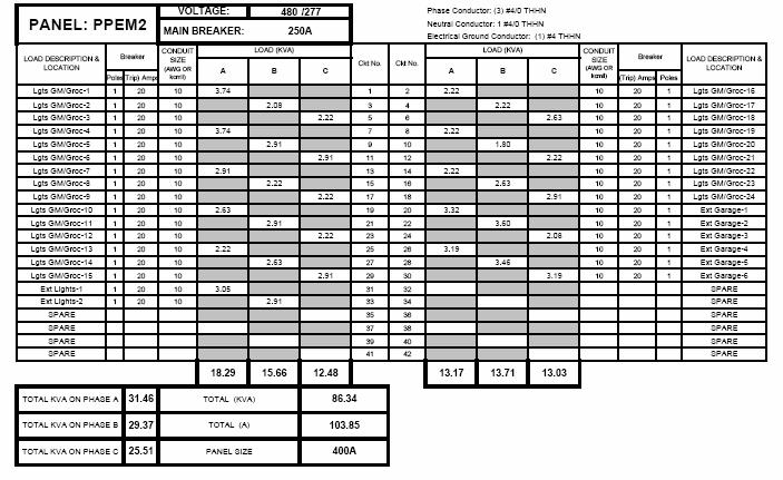
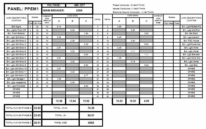
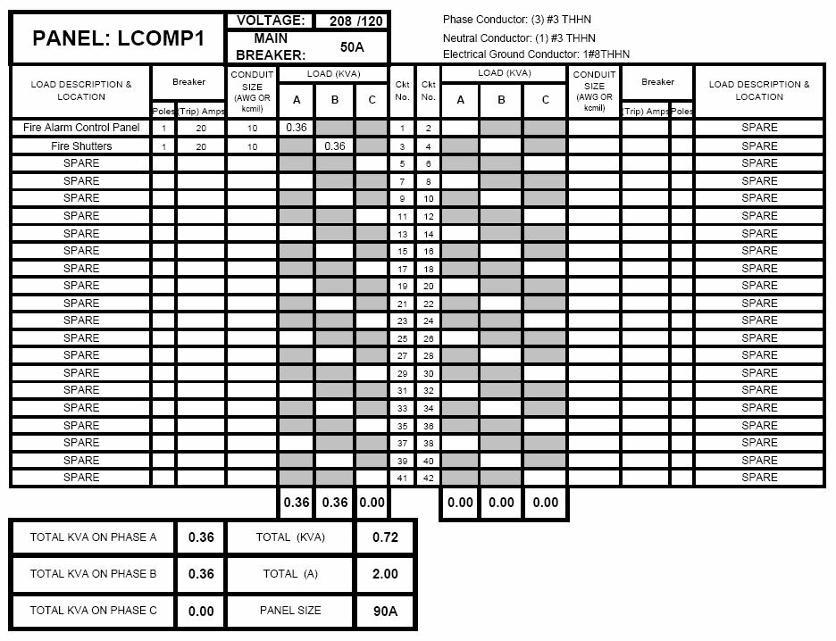
6 New Emergency Lighting Panels: Panel Voltage KVA Demand Spare KVA I j Total KVA I (Amps) PPEM PPEM LVEM Panel Panel Breaker Conductor Size Conduit Size (in) Panel Size (Amps) PPEM1 250A, 3P (4) #4/0 THHN PPEM2 250,3P (4) #4/0 THHN LVEM1 50A, 3P (4) #4THHN 1 90 New Emergency Lighting Transformer: xtformer Side xtformer KVA Voltage I pri (Amps) Ipri x 1.25 (Amps) TEM1 Primary TEM1 Secondary xtformer Side Breaker Used Wire size (Awg or kcmil) Conduit Size (in) TEM1 Primary 50A, 3P (4) #8 THHN 0.75 TEM1 Secondary 100A, 3P (4) #4 THHN 1.00
7
8

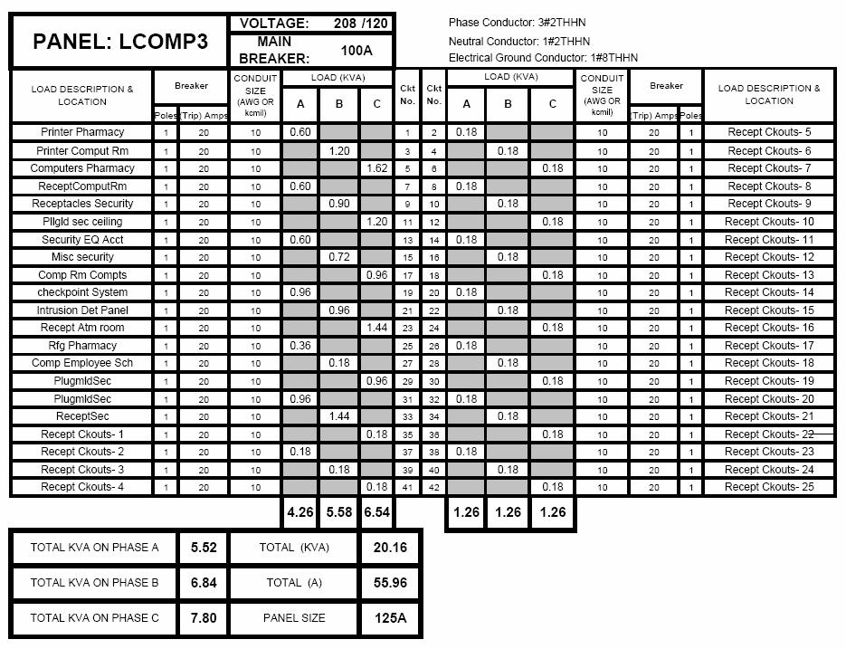
9 New Computer Power Panels: Panel Voltage KVA Demand Spare KVA i j Total KVA I (Amps) PPCOMP LVCOMP LVCOMP LCOMP
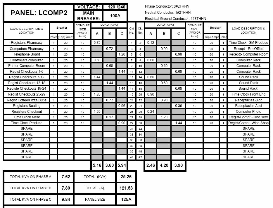
10 Panel Panel Breaker Conductor Size Conduit Size (in) Panel Size (Amps) PPCOMP1 400A, 3P (4) #500 THHN LVCOMP1 50A, 3P (4) # 3 THHN LVCOMP2 100A, 3P (4) #2 THHN LCOMP3 100A, 3P (4) #2 THHN UPS for LCOMP2: UPS Voltage KVA I (Amps) Breaker Conductor Size Conduit Size (in) A, 3P (4) #2 THHN 1.25
11 New Computer Power Panels Transformers: xtformer Side xtformer KVA Voltage I pri (Amps) Ipri x 1.25 (Amps) COMP1 Primary COMP1 Secondary COMP2 Primary COMP2 Secondary COMP3 Primary COMP3 Secondary xtformer Side Breaker Used Wire size (Awg or kcmil) Conduit Size (in) COMP1 Primary 100A, 3P (4) #3 THHN 1.25 COMP1 Secondary 100A, 3P (4) #3 THHN 1.25 COMP2 Primary 100A, 3P (4) #3 THHN 1.25 COMP2 Secondary 250A, 3P (4) #4/0 THHN 2 COMP3 Primary 100A, 3P (4) #3THHN 1.25 COMP3 Secondary 250A, 3P (4) #4/0 THHN 2
12
13
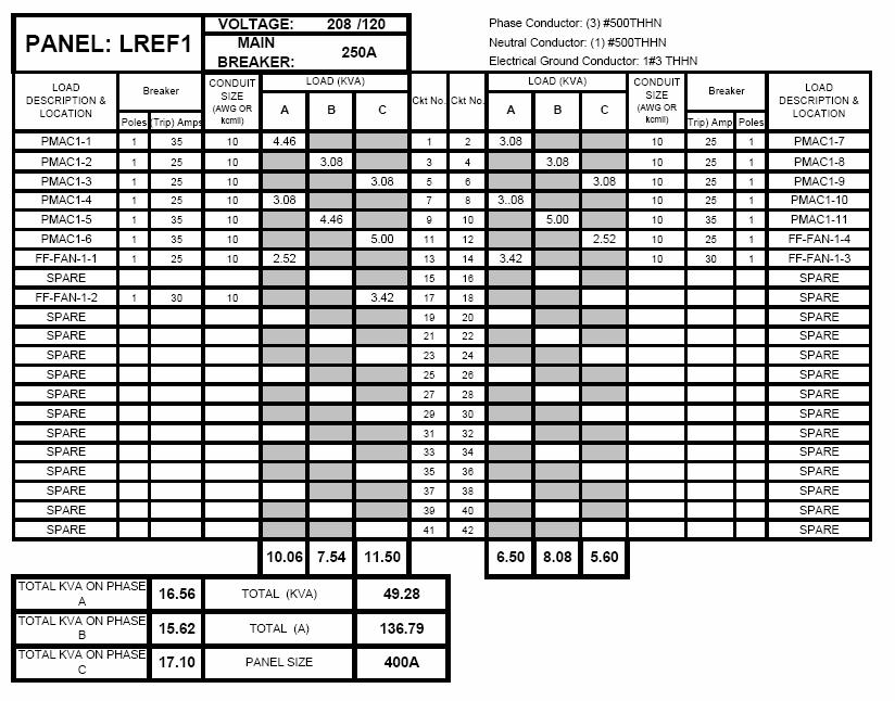
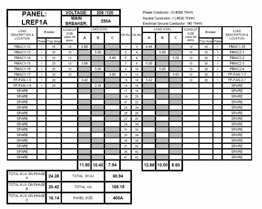
14 New Refrigeration and Elevator Power Panels: Panel Voltage KVA Demand Spare KVA i j Total KVA I (Amps) PPREF LREF LREF1A LREF Panel Panel Breaker Conductor Size Conduit Size (in) Panel Size (Amps) PPREF1 600A, 3P 2 sets of (4) #300 THHN LREF1 250A, 3P (4) #500 THHN LREF1A 250A, 3P (4) #500 THHN LREF2 250A, 3P (4) #500 THHN New Refrigeration and Elevator Power Panels Transformers: xtformer Side xtformer KVA Voltage I pri (Amps) Ipri x 1.25 (Amps) PPREF1 Primary PPREF1 Secondary PPREF2 Primary PPREF2 Secondary Side Breaker Used Wire size (Awg or kcmil) Conduit Size (in) Primary 250A, 3P (4) #250 THHN 2.25 Secondary 600A, 3P 2 sets of (4) #300THHN 3" Primary 250A, 3P (4) #4/0 THHN 2" Secondary 400, 3P (4) #500 THHN 3"
15
16
17
18 2.3.3 Generator Sizing: The loads on each of the 3 three newly created emergency branches were summed to determine the necessary generator size. The KW and KVA loads for lighting and receptacles were simply calculated from the given ampacity and the rated voltage. A power factor of 0.9 was assumed for the lighting and receptacle loads. All mechanical and refrigeration equipment was sized from their specified ampacity or horsepower to estimate their KVA and KW. All mechanical equipment was assumed to have a power factor of 0.8. To determine the generator size, I used a method described to me by my electrical consultant John Reese. Sizing the generator starts with sizing the loads for the life safety branch (emergency lighting), the loads were totaled for RKVA and starting KVA. After this, the emergency Computer panels start up, and then the starting load is added to the running load of the life safety branch. Then, the mechanical and refrigeration equipment is started last on the emergency distribution system and added the running RKVA of the previous two branches. After power factors were applied and safety factors were added to the capacity, a total demand KVA was compiled and that total KVA was converted to KW. Assumptions: 0.9 PF for Life Safety (Emergency Branches) 0.9 PF for Computer Branch 0.8 PF for Mechanical Equipment 600% of motor full-load Generator Sizing Emergency Branch Loads SKVA RKVA SKW RKW Total KVA Total KW Life Safety (Emergency Lighting) Computer Branch Mechanical/Refrigeration Branch
19 Total KVA Total KW Critical Condition % Growth Design Emergency Power Redesign Conclusion: The redesign of the emergency distribution system accomplished its goals of creating a more simplified, less expensive system. This study started because of Wegmans desire to create a new standard for their emergency distribution system. My study first evaluated what loads were crucial and what loads are not crucial to maintaining operations as close to normal as possible in their main grocery space. From this a detailed list of essential and optional desired power loads for the sized down emergency generation system was found. The vast majority of loads were emergency lighting, computer, and refrigeration loads. The final solution was a single 500kw generator. The redesigned emergency system cannot nearly back-up the entire building like the existing system but a value engineering analysis shows that the decrease in initials cost and maintenance could provide more bang for its buck. Selecting a scaled back approach and basically only keeping critical loads and loads which only allows the grocery portion of the building to operate as normal, the new sized down emergency system provides an alternative to the expensive existing system. The owner would have to make a decision based on whether spending this much additional costs would return profits through being able to keep the entire building open during a power failure. Price Breakdown: Existing System (Twin 900KW w/interlocking system): $486,000 New System (Single 500KW): $105,000
20 2.4 Fault Current Analysis: Fault current analysis allows us to predict the maximum available current at various points in the electrical system. A fault current analysis was done with the assistance of the Electrical Designer s Reference Program. AIC ratings were given for each panel picked on the critical path which was chosen to travel from the MDP all the way to the end of the paths at LCOMP1, LCOMP2, and LCOMP3. These critical paths were chosen due to the distance of the Panels from the MDP and distance the ampacity has to travel. It is mandatory that all equipment be properly rated for interrupting or withstanding the maximum available fault current at each point in the distribution system. To insure that all applicable electrical equipment is adequately rated to withstand or interrupt the available fault current, the magnitude of the maximum possible fault current must be determined for each point in the electrical distribution system Panel Isc AIC Rating MDP 60,143 65,000 PPCOMP1 47,648 54,000 LLCOMP1 17,900 20,000 LLCOMP2 8,051 10,000 LLCOMP3 6,264 10,000
Recommended Procedures
 Selective Coordination Study Recommended Procedures The following steps are recommended when conducting a selective coordination study.. One-Line Diagram Obtain the electrical system one-line diagram that
University of California, San Diego Cal (IT) 2 Technical Assignment #2. Brian Smith
 2 Technical Assignment #2. Brian Smith") University of California, San Diego Cal (IT) 2 Technical Assignment #2 Brian Smith Advisor: Dr. Moeck 31 October 2005 Brian Smith Lighting/Electrical Option University of California, San Diego Cal (IT)
University of California, San Diego Cal (IT) 2 Technical Assignment #2 Brian Smith Advisor: Dr. Moeck 31 October 2005 Brian Smith Lighting/Electrical Option University of California, San Diego Cal (IT)
CHAPTER V RESIDENTIAL WIRING
 CHAPTER V RESIDENTIAL WIRING 5.1. THE SERVICE ENTRANCE Buildings and other structures receive the electrical energy through the service entrance. In residential wiring, the electric company supply this
Electrical Depth. Mark W. Miller Sibley memorial Hospital Grand Oaks Washington, DC CURRENT SYSTEM
 CURRENT SYSTEM The current electrical system can best be described as star; one main switchboard that feeds to the main distribution panel, which then feeds the other panels. The normal power is provided
2000 Cooper Bussmann, Inc. Page 1 of 9 10/04/00
 DO YOU KNOW THE FACTS ABOUT SINGLE-POLE INTERRUPTING RATINGS? YOU MAY BE IN TROUBLE! Typical plant electrical systems use three-phase distribution schemes. As an industry practice, short-circuit calculations
Customer Requirements Downtown Secondary Network Service
 Application This standard describes the limitations and requirements for receiving service from the Tacoma Power secondary network system within the City of Tacoma downtown core area. In This Standard
Design considerations for generator set mounted paralleling breakers
 Our energy working for you. Design considerations for generator set mounted paralleling breakers White Paper Hassan Obeid, Application Group Cummins Power Generation Cummins Power Systems has been delivering
Gregory Wolfe 2004 Senior Thesis Lighting / Electrical
 Electrical Depth The current electrical one-line diagram for the is a radial system with one switchboard with 21 panelboards off it. However, by redesigning the lighting systems in the gathering space,
Electrical Design/Build Guide
 2017 Electrical Design/Build Guide Based on the 2017 National Electrical Code Copyright Durand & Associates 1986-2016 60 C Copper Ampacity 4 - Wire Fill - (Non-Current Carrying Neutral) 4 or 5 - Parallel
DESIGN GUIDELINES LOW VOLTAGE SWITCHGEAR PAGE 1 of 5
 DESIGN GUIDELINES LOW VOLTAGE SWITCHGEAR PAGE 1 of 5 1.1. APPLICABLE PUBLICATIONS 1.1.1. Publications listed below (including amendments, addenda, revisions, supplements, and errata), form a part of this
Pretest Module 24 Three-phase Service Entrance
 Pretest Module 24 Three-phase Service Entrance 1. What is the most widely used three-phase service entrance system? 2. What are the three most common voltage combinations for three-phase, four-wire systems?
Quick Start Guide TS 910 & TS 920
 Quick Start Guide TS 910 & TS 920 DANGER HAZARD OF ELECTRICAL SHOCK, EXPLOSION, OR ARC FLASH Read and understand this quick start guide before installing and operating the transfer switch The installer
PART A General Conductor Requirements
 PART A General Conductor Requirements 6.1 Conductor Insulation Property Table 310.13 of the NEC provides information on conductor properties such as permitted use, maximum operating temperature, and other
Quick Start Guide TS 910
 Quick Start Guide TS 910 DANGER HAZARD OF ELECTRICAL SHOCK, EXPLOSION, OR ARC FLASH Read and understand this quick start guide before installing and operating the transfer switch The installer is responsible
Data Bulletin. Wire Temperature Ratings and Terminations INTRODUCTION WHY ARE TEMPERATURE RATINGS IMPORTANT?
 Data Bulletin March 2002 Lexington, KY, USA Wire Temperature Ratings and Terminations INTRODUCTION WHY ARE TEMPERATURE RATINGS IMPORTANT? Table 1: Insulation Type Figure 1: Figure 2: Ampacity of a 1/0
Selective Coordination Enforcement:
 Selective Coordination Enforcement: Overcurrent Protective Device Basics by Tim Crnko The Basics of Selective Coordination Merely having a higher ampere overcurrent protective device (OCPD) feeding a lower
Spring Test 7 due 05/03/2013
 Spring Test 7 due 05/03/2013 Multiple Choice Identify the choice that best completes the statement or answers the question. 1. A raceway contains two 3-phase, 3-wire circuits that supply 38 ampere continuous
9/16/2010. Chapter , The McGraw-Hill Companies, Inc. TRANSMISSION SYSTEMS. 2010, The McGraw-Hill Companies, Inc.
 Chapter 3 TRANSMISSION SYSTEMS 1 Transmitting large amounts of electric energy over long distances is accomplished most efficiently by using high-voltages. Without transformers the widespread distribution
10 Commercial, Industrial, Agricultural Services
 10 Commercial, Industrial, Agricultural Services This section describes the Power Company requirements for commercial, industrial, and agricultural services. This section covers single phase and three
90.2 Scope. The installation of electrical conductors, equipment and raceways for:
 NEC Generator Primer Rules on the installation of generators and transfer switches 1 90.2 Scope The installation of electrical conductors, equipment and raceways for: public and private premises Conductors
Circuit Concepts (Residential)
") Youth Explore Trades Skills Circuit Concepts (Residential) Description This Activity Plan will allow students to understand how electrical circuits work in a home. Students will also gain knowledge of
Youth Explore Trades Skills Circuit Concepts (Residential) Description This Activity Plan will allow students to understand how electrical circuits work in a home. Students will also gain knowledge of
Corrections most seen on plan review October 18, 2017 David Rankin Seattle Department of Construction and Inspections
 Corrections most seen on plan review October 18, 2017 David Rankin Seattle Department of Construction and Inspections One-Line / Riser Diagrams Drawings are not reviewed prior to submission. Because of
Power Quality and Protective Device Coordination: Problems & Solutions Part 1 Undersizing of Utility Main Service Transformers
 Power Quality and Protective Device Coordination: Problems & Solutions Part 1 Undersizing of Main Service s INTRODUCTION by Robert E. Fuhr, P.E. The use of electronic equipment has dramatically increased
Electrical Depth. Josh Kreutzberger Lighting/Electrical
 Electrical Depth Electrical Introduction The current power distribution system provides the building with power; however, an alternative design solution was analyzed. This analysis was done in order to
External Hard Drive: A DFMA Redesign
 University of New Mexico External Hard Drive: A DFMA Redesign ME586: Design for Manufacturability Solomon Ezeiruaku 4-23-2013 1 EXECUTIVE SUMMARY The following document serves to illustrate the effects
UNIVERSITY OF WASHINGTON Facilities Services Design Guide. Electrical. Switchboards. Basis of Design. Design Evaluation
 Basis of Design This section applies to the design relating to low voltage switchboards. Design Criteria UW Class N1 facilities main switchboards shall be rear accessible. The main, tie and feeder breakers
Appendix C. Design Calculations for Electrical Design. Chapter 9 Electrical Design Edition SPU Design Standards and Guidelines 9C-i
 AppC_Ch9-DesignClac_8.9.10 Chapter 9 Electrical Design Appendix C Design Calculations for Electrical Design 2010 Edition SPU Design Standards and Guidelines 9C-i Appendix C Design Calculations 9C-ii 2010
Equipment Protection. Transformers 600V or Less
 Equipment s or Less The requirements of 450.3 cover only transformer protection. In practice, other components must be considered in applying circuit overcurrent protection. For circuits with transformers,
MECKLENBURG COUNTY. Land Use and Environmental Service Agency Code Enforcement 2/8/12 ELECTRICAL CONSISTENCY MEETING. Code Consistency Questions
 MECKLENBURG COUNTY Land Use and Environmental Service Agency Code Enforcement 2/8/12 ELECTRICAL CONSISTENCY MEETING Code Consistency Questions 1. I am inspecting a building addition. They have a 480V to
ABB POWER SYSTEMS CONSULTING
 ABB POWER SYSTEMS CONSULTING DOMINION VIRGINIA POWER Offshore Wind Interconnection Study 2011-E7406-1 R1 Summary Report Prepared for: DOMINION VIRGINIA POWER Report No.: 2011-E7406-1 R1 Date: 29 February
RT Series Step Down Transformer for RT Series UPS 6-10kVA UL Input Vac Output Vac User Guide
 RT Series Step Down Transformer for RT Series UPS 6-10kVA UL Input 208-240 Vac Output 208-120 Vac User Guide UNLESS SPECIFICALLY AGREED TO IN WRITING, SELLER (A) MAKES NO WARRANTY AS TO THE ACCURACY, SUFFICIENCY
8300 Series Installation Guidelines
 1-800-443-4859 8300 Series Installation Guidelines WARNING: RISK OF ELECTRICAL SHOCK OR BURNS. THIS CONVERTER ASSEMBLY SHOULD BE INSTALLED BY A QUALIFIED ELECTRICIAN OR CERTIFIED RV TECHNICIAN. IMPROPER
400/230 Volt 60Hz UPS Power
 olt 60Hz Power Using ual Voltage standby generation and in one Nothing protects quite like Piller www.piller.com Contents 1 Abstract...3 2 Introduction...4 3 Alternative Power istribution...6 4 Integrating
Service Entrance Methods
 Service Section Typical switchboards consist of a service section, also referred to as the main section, and one or more distribution sections. The service section can be fed directly from the utility
An advisory circular may also include technical information that is relevant to the rule standards or requirements.
 Revision 0 Electrical Load Analysis 2 August 2016 General Civil Aviation Authority advisory circulars contain guidance and information about standards, practices, and procedures that the Director has found
CHILLER MODEL NO. YS SOLID STATE STARTER, MODEL NO. SSS, L B OPTIONAL FACTORY INSTALLED DISCONNECT SWITCH AMPS OR
 WIRING DIAGRAMS CONTRACTOR ORDER NO. JCI CONTRACT NO. JCI ORDER NO. Supersedes: 160.80-PW4 (1099) Form: 160.80-PW4 (215) FIELD CONNECTIONS ROTARY SCREW CHILLER WITH GRAPHIC CONTROL CENTER AND YORK MOD
Grounding Of Standby & Emergency Power Systems
 July / August 2007 ELECTRICAL LINE 53 Grounding Of Standby & Emergency Power Systems By Andrew Cochran Power continuity is essential in many industrial and commercial installations where a trip out due
Suggestion on How to Use
 Suggestion on How to Use Industry Trainers are encouraged to use this material in their sessions Download both the PowerPoint file (.ppt) and script file (.pdf) Print the script file (.pdf) and read the
Mar H: SUPPLEMENTAL PARALLELING GEAR (16315-H)
") 2101 Commonwealth Blvd, Suite B Ann Arbor, MI 48105-5759 www.med.umich.edu/facilities/plan/ 263010-H: SUPPLEMENTAL PARALLELING GEAR (16315-H) Related Sections Basis Guideline: N/A For an explanation of
2101 Commonwealth Blvd, Suite B Ann Arbor, MI 48105-5759 www.med.umich.edu/facilities/plan/ 263010-H: SUPPLEMENTAL PARALLELING GEAR (16315-H) Related Sections Basis Guideline: N/A For an explanation of
Installing a Downstream Distribution Panelboard
 Job Sheet 5 Installing a Downstream Distribution Panelboard OBJECTIVE To install a downstream distribution panelboard (DDP) on the Mobile Workstation. To mechanically and electrically connect the DDP to
Reliable Power Distribution Design for Water and Wastewater Facilities By Van Wagner, P.E., Schneider Electric Water Wastewater Competency Center
 Schneider Electric February, 2009 Reliable Power Distribution Design for Water and Wastewater Facilities By Van Wagner, P.E., Schneider Electric Water Wastewater Competency Center Introduction Reliable
Low Voltage Momentary Short Circuit Analysis Report Per Unit Method - IEEE Standards 141, 242
 Low Voltage Momentary Short Circuit Analysis Report Prepared By: Dan Laws Company: Dolphins Software Utility Co.: XFMR Type: Delta to Wye 1000 kva, 3Ø, 60Hz Voltages: 13,200V pri / 480V sec Impedance:
Applying Interrupting Rating: Circuit Breakers
 The professional engineer must be qualified by primarily working in the design or maintenance of electrical installations. Documents on the selection shall be stamped and available to all necessary parties.
Applying Interrupting Rating: Circuit Breakers
 Series Rating: Protecting Circuit Breakers Generally, a circuit breaker should not be applied where the available shortcircuit current at its line side terminals exceeds the circuit breaker s interrupting
PID 274 Feasibility Study Report 13.7 MW Distribution Inter-Connection Buras Substation
 PID 274 Feasibility Study Report 13.7 MW Distribution Inter-Connection Buras Substation Prepared by: Entergy Services, Inc. T & D Planning L-ENT-17A 639 Loyola Avenue New Orleans, LA 70113 Rev Issue Date
Section SWITCHBOARDS. Introduction. Part 1 - General. Related Work
 Section 16435 - SWITCHBOARDS Introduction Part 1 - General Related Work Section 16070 Seismic Anchorage and Restraint Section 16075 Electrical Identification Section 16080 Power Distribution Acceptance
RU SERIES UPGRADE TempAssure Compatible
 RU SERIES UPGRADE TempAssure Compatible This converter section has been designed as a converter section replacement in the following MagneTek or Parallax Power Supply series products and models with DC
Understanding National Electric Code (NEC) tap rules How do they apply to circuit breaker terminals?
 tap rules How do they apply to circuit breaker terminals?") White paper Understanding National Electric Code (NEC) tap rules How do they apply to circuit breaker terminals? Darryl Moser, Business Development Manager, DEM Sales, ABB, Electrification Products Division
White paper Understanding National Electric Code (NEC) tap rules How do they apply to circuit breaker terminals? Darryl Moser, Business Development Manager, DEM Sales, ABB, Electrification Products Division
POWERING THE WAY Rental Power Planner. 877.YOUR.PWR ( ) holtcat.com. Your Business Powered Anywhere.
 holtcat.com. Your Business Powered Anywhere.") POWERING THE WAY Rental Power Planner holtcat.com Your Business Powered Anywhere. PLANNING FOR TEMPORARY POWER: A Critical Management Duty As a facility manager, you know better than anyone that electrical
POWERING THE WAY Rental Power Planner holtcat.com Your Business Powered Anywhere. PLANNING FOR TEMPORARY POWER: A Critical Management Duty As a facility manager, you know better than anyone that electrical
Code Calculations. for an Off-Grid PV System
 Code Calculations for an Off-Grid PV System John Wiles Sponsored by the Photovoltaic Systems Assistance Center, Sandia National Laboratories Judy LaPointe s home is on its way to becoming a finished, off-grid
INTERCONNECTION STANDARDS FOR PARALLEL OPERATION OF SMALL-SIZE GENERATING FACILITIES KILOWATTS IN THE STATE OF NEW JERSEY
 INTERCONNECTION STANDARDS FOR PARALLEL OPERATION OF SMALL-SIZE GENERATING FACILITIES 10-100 KILOWATTS IN THE STATE OF NEW JERSEY January 1, 2005 Rockland Electric Company 390 West Route 59 Spring Valley,
UNDERSTANDING ELECTRICAL EQUIPMENT AND CONDITIONS OF INCREASED RISK
 UNDERSTANDING ELECTRICAL EQUIPMENT AND CONDITIONS OF INCREASED RISK 5 October 2017 John A. Weber Principal Electrical Engineer, Hartford Steam Boiler Inspection and Insurance Company Electrical Power Transmission
Thomas R. Proctor High School
 System Overview Thomas R. Proctor High School has been upgraded from an existing radial electrical system to an expanded radial system. The new system incorporates two separate substations, one located
Renewable Energy Systems 14
 Renewable Energy Systems 14 Buchla, Kissell, Floyd Chapter Outline The Electric Power Grid 14 Buchla, Kissell, Floyd 14-1 THREE-PHASE AC 14-2 THREE-PHASE TRANSFORMERS 14-3 GRID OVERVIEW 14-4 SMART GRID
Electric Drive Vehicle Infrastructure Training. Instructor s Manual. National Alternative Fuels Training Consortium
 Electric Drive Vehicle Infrastructure Training Instructor s Manual National Alternative Fuels Training Consortium Part 4: : Service Panel to Receptacle Overview of Service Panel The role of the service
Standby Electric Generators for Alaskan Residences. Advice & Installation
 Standby Electric Generators for Alaskan Residences Advice & Installation 452-1151 1-800-770-GVEA www.gvea.com Use of this publication is not a substitute for the use of sound judgement by the user. This
Shippensburg University
 Shippensburg University 1871 Old Main Drive Shippensburg, PA 17257 SUPPLEMENT 1 Electrical Coordination Study Professional: Entech Engineering, Inc. 4 South Fourth Street P.O. Box 32 Reading, PA 19603
Overcurrent Protection According to the 2011 NEC
 Overcurrent Protection According to the 2011 NEC Utah Electrical License This course will cover overcurrent protection according to the 2011 NEC. The key sections of Article 240 will be discussed. Overcurrent
Advanced Guide To Understanding Assembly Short-Circuit Current Rating WITH ENGINEERING SOLUTIONS AND OVERCURRENT PROTECTION DEVICES TO ENHANCE SCCR
 Advanced Guide To Understanding Assembly Short-Circuit Current Rating WITH ENGINEERING SOLUTIONS AND OVERCURRENT PROTECTION DEVICES TO ENHANCE SCCR Assembly Short-Circuit Current Ratings What Is A Short-Circuit
Selective Coordination Requirements
 Selective Coordination Requirements Background Selective coordination of all upstream overcurrent protective devices in the supplying circuit paths is required by the NEC for a limited number of specific
TRANSMISSION SYSTEMS
 TRANSMISSION SYSTEMS Transmitting large amounts of electric energy over long distances is accomplished most efficiently by using high-voltages. Without transformers the widespread distribution of electric
RESIDENTIAL GUIDELINE FOR ELECTRICAL VEHICLE (EV) CHARGER INSTALLATION
 CHARGER INSTALLATION") RESIDENTIAL GUIDELINE FOR ELECTRICAL VEHICLE (EV) CHARGER INSTALLATION The purpose of this guideline is to assist homeowners and contractors in streamlining the permitting and installation process for
RESIDENTIAL GUIDELINE FOR ELECTRICAL VEHICLE (EV) CHARGER INSTALLATION The purpose of this guideline is to assist homeowners and contractors in streamlining the permitting and installation process for
Chapter 6 Generator-Voltage System
 Chapter 6 Generator-Voltage System 6-1. General The generator-voltage system described in this chapter includes the leads and associated equipment between the generator terminals and the low-voltage terminals
2018 Consultant s Handbook Division 26 Electrical 2413 Switchboards
 1 General 1.1 Switchboards shall be U.L. listed and labeled. 1.2 Each switchboard shall have its own main disconnecting means unless it is located in the same room as its source of origin. In most cases
Copyright 2003 Advanced Power Technologies, Inc.
 Overview of the Standard for Interconnecting Distributed Resources with Electric Power Systems, IEEE 1547 and it s potential impact on operation of the Distributed Generation (DG) systems and on the design
IEEE Guide for the Design of Low Voltage AC and DC Auxiliary Systems for Substations
 1 IEEE1818-2017 Guide for the Design of Low Voltage AC and DC Auxiliary Systems for Substations Sponsored by the IEEE Substations Committee Presented By Joe Gravelle Organization of the Guide 1. Scope
Wegmans Fairfax Joseph B. Lookup Electrical System Existing Conditions Report & Building Load Summary Report. Appendix Tech Assignment # 2
 Wegmans Fairfax Joseph B. Lookup Electrical System Existing Conditions Report & Building Load Summary Report Appendix Tech Assignment # 2 I Wegmans Fairfax Joseph B. Lookup Electrical System Existing Conditions
MDS2 Series. Modular Distribution Systems. Introduction 8-Position Configuration Decision Tables
 MDS2 Series Modular Distribution Systems Introduction 8-Position Configuration Decision Tables 207 208 209 MDS2 Series Modular Distribution Systems INTRODUCTION Sensata Technologies provides circuit-on-demand
Now - Up To 400A Mains!
 Quik-Spec Family Specification has never been easier or faster for the distribution products you need to achieve selective coordination, and improve electrical system safety and performance Quik-Spec Coordination
Standby Power Systems
 Source: Power Quality in Electrical Systems Chapter 13 Standby Power Systems The term standby power systems describes the equipment interposed between the utility power source and the electrical load to
Electrical Design Guide. This page is intentionally blank.
 Revision: 00 Page 4 of 153 This page is intentionally blank. Revision: 00 Page 5 of 153 TABLE OF CONTENTS 1 Introduction... 11 1.1 Scope of the Standard... 11 1.2 Application... 11 1.3 Definitions... 12
EON Model EL3 Three Phase Centralized Emergency Lighting Inverter. General Specification 10KW 33KW Systems
 EON Model EL3 Three Phase Centralized Emergency Lighting Inverter General Specification 10KW 33KW Systems 1.0 GENERAL This specification defines the electrical and mechanical characteristics and requirements
Overcurrent Protection (2014 NEC) (Homestudy)
 (Homestudy)") Overcurrent Protection (2014 NEC) (Homestudy) Oregon Electrical License The key sections of Article 240 will be discussed. Overcurrent protection for panelboards, appliances, motors, motor compressors,
Overcurrent Protection (2014 NEC) (Homestudy) Oregon Electrical License The key sections of Article 240 will be discussed. Overcurrent protection for panelboards, appliances, motors, motor compressors,
Quick Connection Panel (QCP) Installation Guide
 Installation Guide") Quick Connection Panel (QCP) Installation Guide DANGER HAZARD OF ELECTRICAL SHOCK, EXPLOSION, OR ARC FLASH Read this document first. The installer is responsible for compliance with National Electrical
Quick Connection Panel (QCP) Installation Guide DANGER HAZARD OF ELECTRICAL SHOCK, EXPLOSION, OR ARC FLASH Read this document first. The installer is responsible for compliance with National Electrical
CLIF NOTES SERIES (Competent Leveraging of Information and Facts) ELECTRICAL
 ELECTRICAL") CLIF NOTES SERIES (Competent Leveraging of Information and Facts) ELECTRICAL What basic information do you need to know about electrical systems in buildings and why? The Capital Partners Electrical CLIF
CLIF NOTES SERIES (Competent Leveraging of Information and Facts) ELECTRICAL What basic information do you need to know about electrical systems in buildings and why? The Capital Partners Electrical CLIF
This is intended to provide uniform application of the codes by the plan check staff and to help the public apply the codes correctly.
 SUPPLEMENTAL CORRECTION SHEET FOR SOLAR PHOTOVOLTAIC SYSTEMS (ELEC) This is intended to provide uniform application of the codes by the plan check staff and to help the public apply the codes correctly.
Engineering Dependable Protection
 Electrical Distribution System Engineering Dependable Protection Engineering Dependable Protection - Part II "Selective Coordination of Overcurrent Protective Devices" Table of Contents Page Basic Considerations
Electrical Tech Note 106
 Electrical Tech Note 106 Biosystems & Agricultural Engineering Department Michigan State University Master Exam Study Guide and Sample Questions 1 Based on the 2014 NEC, Part 8 of PA 230, PA 407, and the
www. ElectricalPartManuals. com Engineering Dependable Protection
 Electrical Distribution System Engineering Dependable Protection Engineering Dependable Protection - Part II "Selective Coordination of Overcurrent Protective Devices" Table of Contents Page Basic Considerations
Fuseology. Fuse Holders, Fuse Blocks, Power Distribution Blocks & Surge Suppression. Optima Fuse Holders & Overcurrent Protection Modules.
 Fuseology Fuse Holders, Fuse Blocks, Power Distribution Blocks & Surge Suppression Optima Fuse Holders & Overcurrent Protection Modules Compact, full-featured modules that deliver Type 2 coordinated protection,
WARNING. Instructions for Combination Bypass Isolation and Transfer Switches Amps I.L A FILE APPLICATION SAFETY PRACTICES
 FILE 29-900 Instructions for Combination Bypass Isolation and Transfer Switches 100-1000 Amps APPLICATION The Cutler-Hammer combination Bypass Isolation and Transfer Switches are listed under Underwriters
Design Standards NEMA
 Design Standards Although several organizations are involved in establishing standards for the design, construction, and application of motor control centers, the primary standards are established by UL,
Going the Distance - Solving Power Reach Issues With Diverse DAS Solutions
 GE Critical Power Going the Distance - Solving Power Reach Issues With Diverse DAS Solutions Paul Smith Technical Marketing Manager GE Critical Power Paul Smith (214) 385-9070 Paul.D.Smith@GE.com Terrell
The Reliable Choice. Field Pocket Guide
 The Reliable Choice Field Pocket Guide Allowable Ampacities of STABILOY Brand XHHW-2 and Copper 75 C (167 F) 90 C (194 F) 75 C (167 F) 90 C (194 F) Conductor Size (AWG or kcmil) Types RHW, THHW, THW, THWN,
MODULAR THREE-PHASE AND SINGLE-PHASE UPS SYSTEM
 MODULAR THREE-PHASE AND SINGLE-PHASE UPS SYSTEM PowerLine DPA 20 120 kva Full power for industrial applications PowerLine DPA 20 120 kva Full power for industrial applications 2 ABB UPS SYSTEMS POWERLINE
3.6 KVA IsoG2. INSTALLATION INSTRUCTIONS & OWNER S MANUAL Model 93-ISOG26-A LT ISOG26 1. Issue 1 Print 3 SHORELINE ISOLATION TRANSFORMER
 3.6 KVA IsoG2 SHORELINE ISOLATION TRANSFORMER INSTALLATION INSTRUCTIONS & OWNER S MANUAL Model 93-ISOG26-A 1 Issue 1 Print 3 Contents INTRODUCING... THE 3.6 KVA IsoG2............................................................
Load Side PV Connections
 Perspectives on PV Load Side PV Connections 705.12(D) in the 2014 NEC by John Wiles Through the exceptional efforts of the members of NFPA NEC Code-Making Panel 4 working with the proposals and comments
Permitting, Installation and Inspection Residential EV Chargers Be aware that there are different types of Electric Vehicle (EV) Chargers.
 Chargers.") Be aware that there are different types of Electric Vehicle (EV) Chargers. There are 2 basic types of EV chargers for home use (Level 1 and Level 2). Level 1 Chargers are smaller units that plug directly
Be aware that there are different types of Electric Vehicle (EV) Chargers. There are 2 basic types of EV chargers for home use (Level 1 and Level 2). Level 1 Chargers are smaller units that plug directly
.3 Section Waste Management and Disposal.
 Issued 2005/06/01 Section 16261 Uninterruptible Power Systems Static Page 1 of 10 PART 1 GENERAL 1.1 RELATED SECTIONS.1 Section 01330 Submittal Procedures..2 Section 01780 Closeout Submittals..3 Section
City of Perris Development Services Building & Safety
 Western Riverside County Code Uniformity Program City of Perris Development Services Building & Safety Residential Electric Vehicle (EV) Charger Guidelines PHONE NUMBER 951-943-5003 Inspection Request
AMENDMENT ELECTRIC SERVICE MANUAL 2014
 AMENDMENT (Pages 20,43,50,72,74,,76,78,83,86,99) ELECTRIC SERVICE MANUAL 2014 Effective April 1, 2015 18-7 6.0 SERVICE AND SERVICE ENTRANCES (General), Continued Conductor Sizing It is recommended that
NEC REQUIREMENTS FOR GENERATORS
 PROFESSIONAL DEVELOPMENT SEMINAR SERIES NEC REQUIREMENTS FOR GENERATORS (Based on NEC 2005 with limited 2008 commentary) AIA certified Continuing Education Units (CEU) Available GPS-140 National Electric
TESCO THE EASTERN SPECIALTY COMPANY Date: 05/04/15 Canal Street and Jefferson Avenue Bristol, PA 19007
 Table of Contents DESCRIPTION PAGE 1.1 Cat. 1044A (What it is)... 2 1.2 Selector Switches... 2 1.3 Leads... 2 CURRENT TRANSFORMERS 2.1 Tests... 2 2.2 Function of Catalog 1044A... 3 2.3 Internal C.T. Defects...
Electric & Gas Service Requirements (Greenbook) Overview
 Overview") INTRODUCTION The Greenbook contents and standard documents are updated regularly to provide users with the most current information possible. In conjunction with this effort, the 2016 Greenbook was reviewed
INTRODUCTION The Greenbook contents and standard documents are updated regularly to provide users with the most current information possible. In conjunction with this effort, the 2016 Greenbook was reviewed
ECET Distribution System Protection. Overcurrent Protection
 ECET 4520 Industrial Distribution Systems, Illumination, and the NEC Distribution System Protection Overcurrent Protection One of the most important aspects of distribution system design is system protection.
SUPPLEMENTAL CORRECTION SHEET FOR SOLAR PHOTOVOLTAIC SYSTEMS - ELECTRICAL
 SUPPLEMENTAL CORRECTION SHEET FOR SOLAR PHOTOVOLTAIC SYSTEMS - ELECTRICAL This is intended to provide uniform application of the codes by the plan check staff and to help the public apply the codes correctly.
ADVANCED CALCULATIONS
 ADVANCED CALCULATIONS 101. Why is it permissible in some cases to fuse a #14 AWG motor conductor with a 60 amp breaker when normally a #14 AWG should only be fused at 15 amps? a) the motor can't start
PDI PowerWave 2 Bus System
 1 GENERAL 1.1 Summary This specification covers the electrical characteristics and general requirements for a continuous opening, low voltage, vertical or horizontal power busway distribution system. System
A. Submit manufacturer's literature and technical data before starting work.
 SECTION 16425 SWITCHBOARD PART 1 GENERAL 1.01 SUMMARY A. Related Section: 1. 16450 - Grounding. 1.02 SUBMITTALS A. Submit manufacturer's literature and technical data before starting work. B. Submit Shop
FIELD CONNECTIONS FOR YK CHILLER (STYLE G) OPTIVIEW CONTROL CENTER WITH REMOTE MEDIUM VOLTAGE SSS
 OPTIVIEW CONTROL CENTER WITH REMOTE MEDIUM VOLTAGE SSS") Supersedes: 160.75-PW2 (508) Form 160.75-PW2 (311) FIELD CONNECTIONS FOR YK CHILLER (STYLE G) OPTIVIEW CONTROL CENTER WITH REMOTE MEDIUM VOLTAGE SSS WIRING DIAGRAM CONTRACTOR ORDER NO. YORK CONTRACT NO.
Supersedes: 160.75-PW2 (508) Form 160.75-PW2 (311) FIELD CONNECTIONS FOR YK CHILLER (STYLE G) OPTIVIEW CONTROL CENTER WITH REMOTE MEDIUM VOLTAGE SSS WIRING DIAGRAM CONTRACTOR ORDER NO. YORK CONTRACT NO.