BMS SV 24S for 2S-24S LiPo, LiFe & LiTO&others Low power consumption High accuracy 2.8 TFT LCD display Programmable
|
|
|
- Erika Lamb
- 5 years ago
- Views:
Transcription

1 BMS SV 24S for 2S-24S LiPo, LiFe & LiTO&others Low power consumption High accuracy 2.8 TFT LCD display Programmable Thanks for your purchasing the for your vehicle. Read the ENTIRE instruction manual to become familiar with the features/functions of the device before operating.
, displayed with TFT color LCD.")
2 is designed special for LiPo,LiFe and LiTo battery pack applied to storage energy system and Electrical Vehicle including EV,E-Motorcycle,E-Scooter so on. The unit can measure or detect the battery voltage, cell voltage, charge & discharge current, battery temperature, and battery SOC(State of Charge), displayed with TFT color LCD. Safety Notes Please read the entire manual completely before using, to make sure you can use this device better and more safely. 1. Ensure the BMS program and settings match your battery pack, otherwise the battery will be damaged and a dangerous situation may arise, especially for Lithium batteries, which may cause fire. 2. For storage energy system application and for Electrical vehicle application will have many differences, please adjust those key parameters carefully, or contact us for more details. 3. Do not allow water, moisture, metal wires or other conductive material into the device. 4. Never charge or discharge any battery having evidence of leaking, expansion/swelling, damaged outer cover or case, color-change or distortion. 5. Do not try to charge non-rechargeable dry cells. 6. Do not mix batteries of different types, different capacities or from different manufacturers. 7. Do not exceed the battery manufacturer s suggested maximum charge and discharge rates. 8. Carefully follow the battery pack manufacturer s recommendations and safety advice. Warning 1. External power supply and battery charger don t have a common ground 2. Current shunt don t contact to any mental including BMS mental case 3. BMS case don t contact to any mental 4. Current shunt must connected to Battery pack negative 5. Prevent BMS from vibrating violently to make sure BMS case don t contact to battery pack negative 6. If power BMS by battery pack, the total current driven charge and discharge relay must be less than 1A, the charge controller and discharge controller voltage is battery pack voltage, so the relay coil voltage must be accordance with battery voltage. Copyright any units or individual extract and copy parts or entire contents of this manual, and transmission in any form is illegal and strictly prohibited. The product described in this manual, may include copyright software ownership belonged to SV green and its licensee, except getting the permission from relevant rights holders, otherwise any copy, distribute, modify, excerpt, decompile, disassemble, decrypt, reverse engineering, lease, transfer, sub-license, as well as other acts of infringement of software copyright is strictly prohibited, but apart from the restrictions prohibited by applicable law.
3 Special Features 1. The uses advanced ADC measurement technology, high accuracy, high voltage and high current detection circuit. The maximum voltage measurements tolerance is within 5mV at up to 24S LiPo battery (102V) 2. Support regenerative braking, during braking operation can charge the batter pack and the discharge power (Wh) will decrease to response to the braking power. 3. Charge/discharge current up to 600A. Bigger current can be customized A per cell balance current is very useful for large capacity battery pack, the feature can resume all cell voltage balance status at the shortest time. Over temperature protection make sure the system safety during balance. 5. calculate and display the charge and discharge power (Wh), generally the battery rated power is rated voltage multiply rated battery capacity. 6. TFT LCD screen provides rich information including current, voltage, power, capacity, battery status, SOC and temperature and so on. 7. features a maximal safety protection, within the range parameters can be setup, will alarm and cutoff charge or discharge according to users setup, out of range of parameters, and trigged absolute maximum ratings will force to cutoff charge or discharge 8. pow..er consumption by draw current from all cells or external power supply. 9. Dual power design, the unit can be powered by all cells or external power supply. 10. Detect cell count at any time, and compare with the count detected when switch on first time. If it is not uniformity, the device will alarm and cutoff charge or discharge according to users setup, the feature can prevent any cell connection from loosing. 11. Sound alarm and LED alarm will be triggered when any warning events happened, and then wait several seconds cut off or Don't cut off charge or discharge. The delay time can be programmed. 12. Charge relay and discharge relay are controlled independently. 13. Two temperature sensors monitor battery temperature on different position. 14. Supports upgrading the firmware program by USB port. 15. provide users the maximal flexibility, key parameters can be programmed. 16. display battery SOC or called battery gauge similar with car dashboard. Cell count, battery pack voltage and battery gauge (%) is displayed simultaneously. 17. In case that the battery pack need not be charged and discharged, Press STOP button enter into sleep mode to save energy consumption, at this mode, Charge and Discharge is forbidden, and LCD back light is off. Press any key to resume normal work mode. 18. LCD back light ON time can be programmed to save energy, when it is OFF, press any key to resume ON. Protection functions 1. Cell count error protection 2. Over charge protection 3. Under voltage protection 4. Over current protection when charge or discharge 5. Over temperature protection 6. Over differential cell voltage protection 7. Over differential battery temperature protection 8. Under SOC protection
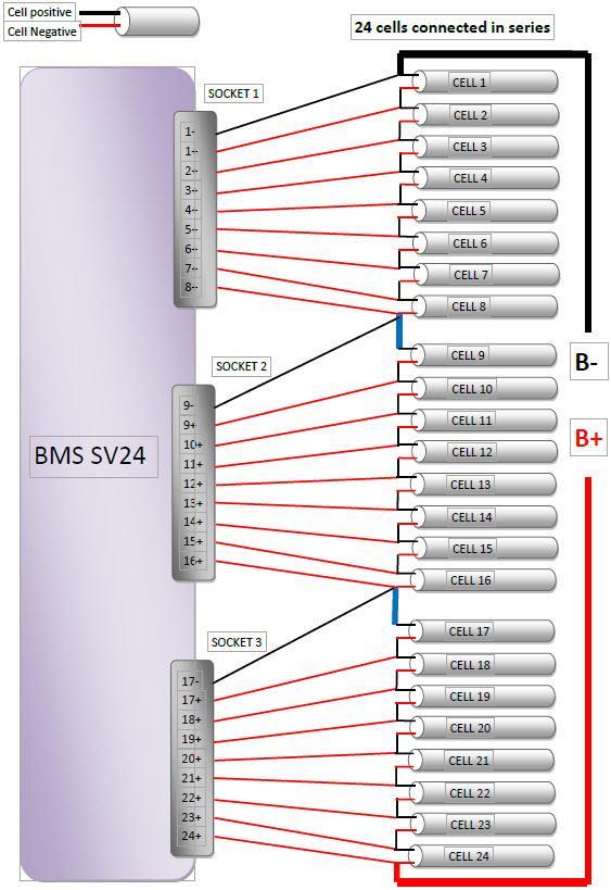
4 Interface Power Selector Battery Pack External Power External power Charge Controller Discharge Controller Temperature Sensor 1 Temperature Sensor 2 COM1 Current Sense USB Socket 1 Cell 1- Cell 1+ Cell 2+ Cell 3+ Cell 4+ Cell 5+ Cell 6+ Cell 7+ Cell 8+ Socket 2 Cell 9- Cell 9+ Cell 10+ Cell 11+ Cell 12+ Cell 13+ Cell 14+ Cell 15+ Cell 16+ Socket 3 Cell 17- Cell 17+ Cell 18+ Cell 19+ Cell 20+ Cell 21+ Cell 22+ Cell 23+ Cell 24+ COM2 BMS24 main module LCD Beeper COM2 USB STOP DOWN UP SET/START BMS24 display module
5 Power Selector External power port Charge controller Discharge controller COM1 COM2 Temperature sensor LED 1) Beeper 1) Current sense USB Socket 1 Socket 2 Socket 3 Alternate External power supply or battery pack to power. If select battery, the battery pack must be 8S to 24S LiFe or LiPo or LiTO. But if power by external power supply, can do 2S-24S LiPo or LiFe battery pack. The main input supply Vin voltage range is 15V to 60V External power input, the voltage should be 15V to 60V, 1A minimum, the current depends on the relay coil, the connector is 5.5*2.1 DC jack, Charge controller, turn on or turn off charge circuit, generally connect to relay or DC contactor. When any cell voltage is over setup, it will make relay OPEN to turn off the charger, otherwise will output Vin power the coil to close the relay. The relay must be form OPEN. Discharge controller, turn on or turn off discharge circuit, generally connect to relay or DC contactor. When any cell voltage is under setup, it will make the relay OPEN to turn off the motor or other load, otherwise will output Vin power the coil to close the relay. The relay must be form OPEN. The COM1 port (black connector) is connected to external device such as Charger. If connect to Charger, can control charge current to shorten charge time The COM2 (gray connector) port is connected to main unit and display module by gray spring wire Two temperature sensors monitor the battery temperature, the sensor must tie to battery surface or gap of cells where the temperature should be the highest during charge or discharge. The temperature range is -20 to 150 Connect to high light LED, the LED will flash when any warning event happened Connect to beeper or others to alarm. It will output 12V 25mA max. Connect to single current shunt. Charge current and discharge current can be measured simultaneously. Connect to PC update the firmware by Charger UpdateTool.exe Connect to 2S to 8S battery, Connect to 9S to 16S battery. for over 8S battery, please connect 8S battery to socket 1 and then connect to socket 2, such as 8S + 2S for 10S and 8S +5S for 13S Connect to 17S to 24S battery. for over 16S battery, please connect 8S battery to socket 1 and second 8S to socket 2, then connect other cells to socket 3, such as 8S + 8S + 6S for 22S Note: 1) On the BMS display module Absolute maximum or Minimum ratings LiPo 4.35V Larger than the absolute maximum voltage, Maximal cell voltage LiFe 3.90V LiTO 2.80V will force to cut off charge LiPo 2.50V Less than the absolute minimum voltage, BMS Minimum cell voltage LiFe 2.00V LiTO 1.50V SV24S will force to cut off discharge Battery temperature LiPo& LiFe&LiTO 80 Over the temperature, will force to cutoff the charge and discharge


6 Program Setup 1. Press SET/START button for 3 seconds enter into Program Setup interface. 2. Press UP or DOWN button select the item, press SET/START shortly make the value flash, and press UP or DOWN change the value. Press SET/START button shortly confirm the change. After finish all setup, press SET/START for 3 seconds quit the setup menu. 3. When quit setup mode, will record all parameters till next change.
7 NOTE: Please keep the default setup unless for special purpose. Parameters Min. Type Max. Step unit Charge Protection LiPo V Over Charge Protection(P) Voltage LiFe V LiTO V LiPo V Over Charge Release(R) Voltage LiFe V LiTO V Over Charge current A Discharge Protection LiPo V Over Discharge Protection(P) Voltage LiFe V LiTO V LiPo V Over discharge Release(R) Voltage LiFe V LiTO V Over Discharge current A SOC--- Battery gauge % Temperature Protection Battery Temperature Difference(Diff) of battery Temperature(Temp) Voltage balance Protection Difference(Diff) of cell voltage mv Others Temperature Unit Key Beeper ON OFF LCD Back-Light time (1) min Cut-Off Delay Time (2) Second Current Calibration (3) A Temperature Alarm (4) ON OFF Cell Empty Voltage (5) V Cell Full Voltage (5) V Default settings Press SET/START restore all parameters to default value before delivery Balance Parameter setup: Press SET/START to setup and press for 3 seconds quit setup Balance Start Voltage (6) LiFe V LiPo V LiTO V Balance Stop Diff Voltage (7) mv Balance in Charge Balance in Discharge Balance (8) ON means Balance start during charge, OFF disable. ON means Balance start during discharge, OFF disable. ON enable Balance, and OFF forbid balance at any situation

8 NOTES: 1. Always on means the LCD back-light will be ON forever. 2. NO means will not cut off charge or discharge but alarm by LED flash and Beeper Sound. Cut-Off Delay Time is very important and difference for different battery capacity and application, please carefully test and make a correct decision, for EV, you can select NO to control the EV car by manual NOT controlled by, but when cell voltage and temperature trigger the absolute maximum or minimum ratings, the will force to cut off charge or discharge to make sure the battery safety, and prevent battery pack from explode or fire. 3. Current Calibration is not recommended unless use new current shunt. Voltage and current is calibrated before delivery. 4. Temperature Alarm OFF means battery temperature and Difference of battery Temperature is unable. 5. Cell Empty Voltage and Cell Full Voltage is to set up cell voltage bar graph, the value should be as same as Over Charge Protection(P) Voltage and Over Discharge Protection(P) Voltage 6. Setup the battery staring voltage, when minimum cell voltage over the setup, balance will start automatically 7. Setup the minimum cell difference, when difference of cell voltage under setup, stop balance automatically 8. Balance switcher, default Balance is OFF, a) If balance switcher is OFF, the BMS don t balance at any situation. b) If balance switcher is ON, balance will start in battery in storage c) If balance switcher is ON, and Balance in charger is ON, balance will start when battery in charge d) If balance switcher is ON, and Balance in discharger is ON, balance will start when battery in discharge e) Balance current is 1.2A max. per cell, Balancer can resume cell voltage balanced status at the shortest time, it is based on 1.2A balance current per cell, balancing accuracy is 8mV. Balance can be operated in charge or in discharge or in both, the feature can be setup on program setup menu. The balance function is unable before delivery, after the BMS display each cell voltage, please enter into program setup menu to enable balance. Although balance current per cell is larger than other brand BMS, Charger BMS SV24 use temperature protection prevent BMS from overheating.

9 Operating guideline 1. Connect Beeper, LED, and Current Sensor to main module, and then connect relay Controller and temperature sensor too. 2. Connect main module to display module by COM2 port 3. Connect the battery to, keep the cell polarity correct. The detailed connection diagram is as the following typical connection drawings. 4. Move the power selector turn on the device. 5. BMS24S will initialize the beeper and LED, beeper sounds once time, then display BMS24S and version, the battery type and cell count interface is displayed. Three battery pack connect to the BMS24S. Press SET/START button to run the BMS24S. After started, battery type and cell count will not be changed unless power off BMS24s. Each cell voltage and other data are displayed correctly. if cell voltage is not displayed correctly, Please check the battery connection Press SET/START button for 3 seconds enter into Program Setup interface, modify Over Charge Current (50A default) and Over Discharge Current (300A default) according to your application. If need balance in Charge or in Discharge, please modify the Balance set on Program Menu. the balance function is off before delivery SOC battery gauge dashboard will be displayed first, as following. Press UP/DOWN button alter other interface. STORAGE is battery status, maybe CHARGE or DISCHARGE (1) Cell count and battery type SOC battery gauge, display 0% lose temperature sensor Battery pack voltage Highest cell voltage Lowest cell voltage Difference of cell voltage Battery temperature Charge or discharge current Charge or discharge power Notes When charge or discharge current less than 1.0A, battery status will be STORAGE.


10 6. The following interface is cell voltage bar graph, the highest and the lowest cell voltage is displayed in RED column. 7. The third interface display all information including all cell voltage. The highest and the lowest cell voltage is displayed in RED text. Difference of cell voltage and difference of battery temperature is displayed. When any warning events triggered, will go to the interface and display error information. Such as if the battery connection break down, the cell count and ERROR will be displayed in turn. If the cell voltage over the setup value, the cell voltage and HIGH will be displayed in turn. 8. When any warning events triggered, Press UP or DOWN, you can check the cell voltage triggered warning events (over charger or over discharge), the voltage will be recorded till next warning.
11 Specifications 1. Battery range: 2S-24S LiPo & LiFe, LTO battery pack on, 2S-16S LiPo & LiFe, LTO battery pack on 2. Accurate scope of the cell voltage: -8mV/+8mV on BMS24T, -5mV/+5mV on BMS SV16S 3. Cell Voltage display range: 0.10~4.99V 4. The voltage of external power:15-60v 5. Balance current:1.2a per cell 6. Temperature display range:-20 ~150, 7. SOC indicator: RED 0~15% of SOC YELLOW 16~35% of SOC GREEN 36~100% of SOC 8. Main module Size: (L W T, mm) or (L W T, inch) 9. Main module weight: 420g excluding accessories 10. Display module size: (L W T, mm) or (L W T, inch) 11. Main module weight: 130g excluding accessories 12. Warning LED: 2.0V, 20mA 13. Warning beeper: 12V, 25mA 14. Package: AL alloy case


12 Current shunt and Current Sensor Specifications Please use correct current shunt according to actual maximal charge and discharge current, singe shunt is enough for, 75mV or less shunt is suggested. Charger can provide all kinds of shunt. All cell voltage and current are calibrated before delivery. The 300A and 600A 75mV specification is as below. 300A shunt weight: 230g 600A shunt weight: 530g Current sensor wire

13 Current Calibration Press SET/START 3 seconds enter into Program Setup and find the Current Calibration, you can calibrate the current to improve the measure accuracy. If use new current shunt, the current must be calibrated again. 1. Turn off charge and discharge, make the current blink, press UP/DOWN modify the value to zero, shortly press SET/START button finish 0A calibration. 2. Connect the current shunt as following calibrate charge current Charger output Positive Battery positive Charge current Calibration Battery negative Charger output Negative To BMS 3. Shortly press SET/START make the current blink and increase the current to new value (up to 125A, it must be less than current shunt, it is better to make it equal to your charge current, the key is the current must be accurate), turn on charger and charge battery at the current, 3 seconds later, press SET/START save the charge current calibration. 4. Connect the current shunt as following calibrate discharge current Discharge current Calibration Load Positive Load Negative Battery positive Battery negative To BMS 5. Press SET/START again and decrease the calibration current to new value (up to -125A, it must be less than current shunt, it is better to make it equal to your motor current, the key is the current must be accurate) turn on motor and discharge battery at the current, 3 seconds later, press SET/START/ save the discharge calibration. 6. Turn off motor, Press SET/START for 3 seconds quit Program Setup, current calibration is finished.
14

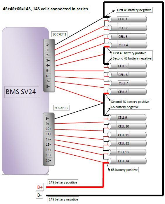
15 Typical Connection There are 3 sockets connecting to battery pack, socket 1 is for 2S-8S, socket 2 for 9S~16S, and socket 3 for 17-24S battery. 1. 6S battery connect to the socket 1 directly, but external power supply is essential, it is as following. 2. For over 8S battery pack, connect 8S to socket 1 and then socket 2 separately. Take 12S battery sample as following:
16
17

18 Heavy RED wires are positive of battery pack (B+/B24+), charger and load such as motor, and heavy black wire is negative of battery pack(b-/b1-), charger and load. Warning Before connect the relay to charge or discharge controller, please confirm the coil of relay voltage. The BMS controller will output Vin to power the coil, if the BMS24 will be powered by external power supply, Vin is external power supply output voltage, if powered by battery pack, Vin will be battery pack voltage. If the Vin is not correct on driving coil, please use voltage regulator to power coil.
19 Charge relay and discharge relay lectotype for If is powered by battery pack, the following items should be considered on using relay. 1. Battery pack voltage range should be accordance with relay coil drive voltage scope. When battery pack is fully charged, the pack voltage is the highest and when the battery is discharge to flat, the pack voltage is the lowest. The relay controller voltage on BMS is battery pack voltage for 8S-16S, and the controller voltage is 16S battery pack voltage for 17S-24S. If controller voltage is not suitable, a buck or boost regulator is essential, the simplest method is use a resistance to decrease the controller voltage to fit with coil voltage. The relay controller can provide 1A current max. 2. Relay DC current should be over 1.2 times as charge or discharge current. If discharge current is 100A, 120A relay for discharge is suitable. 3. If BMS24 is powered by external power supply, the external voltage should be accordance with relay coil drive voltage. Charger + B+ Laod + B+ Coil Charge controller Coil Discharge controller 4. For solid state relay, the driven voltage (+VDC, -VDC), adequate Heats Sink and rated load current is very important, please pay attention to its wire connection.


20 Accessory USB data cable Battery connection XHR-9PIN, 600mm Temperature sensor, 600mm Relay controller wire 600mm Warning LED, 300mm Warning Beeper, 300mm Current sensor wire, 600mm Communication wire (3 meters)
21 Related parts The following device is related with MODEL DESCRIPTION COMMENTS BMS SV16 For 2S-16S, balance is not available. BMSSV16S For 2S-16S, 1.2A balance current per cell AC102 AC charger for 4S-24S battery pack 1-25A charge, 1800W max.


22 Total solution on E-Vehicle application If use SV charger102, the charge relay can be ignored, can communicate with charger by Serial communication port & cable link, when any cell over charged, BMS will send signal to charger, the charger will decrease charge current till the cell voltage under safe value. If use other brand charger, only make the relay OPEN, if charge current is big such as over 10A, the relay will open and close repeatedly. The relay life will be shortened and charge time will be longer. SV charger102 and BMS24S save a relay cost and shorten the charge time. NOTE Charger decrease charge current according to Over Charge Protection(P) Voltage on BMS setup, so please setup the charge terminal voltage setup in accordance with Over Charge Protection(P) Voltage on BMS.


23 Version History Software Version Description V1.05 Released first time V1.06 Fix press STOP enter into sleep mode, and Beeper & LED warning. V1.07 Support LTO battery, model is V1.1 Negative temperature can be measured. V1.13 (Hardware V2.2) Add display module, improve voltage bar graph display Warranty and Service and current Sensor to be free of defects in material and workmanship. This warranty is effective for 12 months from date of purchase. If within the warranty period the customer is not satisfied with the products performance resulting from a manufacturing defect, the accessory will be replaced or repaired. Your selling dealer is your first point of contact for warranty issues. Return postage costs are the responsibility of the user in all cases. Please submit copy of original receipt with the return. Damage due to physical shock (dropping on the floor, etc.), inappropriate power supply (unstable output voltage and insufficient power, etc.), water, moisture, and humidity are specifically NOT covered by warranty. By
BMS24. Thanks for your purchasing the BMS24 for your vehicle.
 BMS24 for 2S-24S LiPo & LiFe Low power consumption High accuracy 2.8 TFT LCD display Programmable Thanks for your purchasing the BMS24 for your vehicle. Read the ENTIRE instruction manual to become familiar
BMS16T BMS24T. Thanks for your purchasing the BMS16T or BMS24T for your vehicle.
 BMS16T BMS24T for 2S-16S or 2S-24S LiPo, LiFe & LiTO Low power consumption High accuracy 2.8 TFT LCD display Programmable Thanks for your purchasing the BMS16T or BMS24T for your vehicle. Read the ENTIRE
BMS16. Thanks for your purchasing the BMS16 for your vehicle.
 BMS16 BMS for 2S-16S LiPo & LiFe Low power consumption High accuracy 2.8 TFT LCD display Programmable Thanks for your purchasing the BMS16 for your vehicle. Read the ENTIRE instruction manual to become
BM16LP. Thanks for your purchasing the cell monitor for your vehicle.
 BM16LP 8S-16S LiPo CELL Monitor Low power consumption High accuracy TFT LCD display Programmable Thanks for your purchasing the cell monitor for your vehicle. Read the ENTIRE instruction manual to become
5006B 5008B 50010B for up to 10S LiPo & LiFe 5mV voltage accuracy 500W charge power 1.3A balance current 2.8 TFT LCD display
 5006B 5008B 50010B for up to 10S LiPo & LiFe 5mV voltage accuracy 500W charge power 1.3A balance current 2.8 TFT LCD display Thanks for your purchasing the 500W CHARGER for your RC. Read the ENTIRE instruction
C4012B for up to 12S LiPo & LiFe & LiTo 5mV voltage accuracy 1500W charge power at AC 500W charge power at DC 1.2A balance current 2.
 C4012B for up to 12S LiPo & LiFe & LiTo 5mV voltage accuracy 1500W charge power at AC 500W charge power at DC 1.2A balance current 2.8 TFT LCD display Thanks for your purchasing the 1500W CHARGER for your
C10325 v1.1. Thanks for your purchasing the intelligent and powerful charger.
 PFC programmable charger 90V~265VAC Input Thanks for your purchasing the intelligent and powerful charger. Read the ENTIRE instruction manual to become familiar with the features/functions of the device
BMS8. Thanks for your purchasing the intelligent BMS8. Read the ENTIRE instruction manual to become familiar with the features/functions of the device
 For 3S~8S LiPo & LiFePO4 Thanks for your purchasing the intelligent Read the ENTIRE instruction manual to become familiar with the features/functions of the device before operating. Feel free to send an
Operating Instructions BPH 35W CHARGER
 Operating Instructions BPH 35W CHARGER Microprocessor controlled high performance Charger / Discharger/ Balancer / Cell Monitor for LiPo & LiFe battery packs. Charge current up to 4.0A, 35W, for 2-4 LiPo
Operating Instructions CHARGERY 680B
 Operating Instructions CHARGERY 680B Synchronous Rectification and microprocessor controlled high performance rapid Charger/Balancer for LiPo, LiFe battery packs with cell balancer. Charge current up to
INTRODUCTION. Specifications. Operating voltage range:
 INTRODUCTION INTRODUCTION Thank you for purchasing the EcoPower Electron 65 AC Charger. This product is a fast charger with a high performance microprocessor and specialized operating software. Please
Instruction Manual BALANCE CHARGER/DISCHARGER FOR NICD/NIMH/LITHIUM/PB BATTERIES
 X6+ AC/DC CHARGER For Sales and support in the USA please contact: Neutronics 11421 West Bernardo Ct San Diego, California 92127 Phone: 858 674 2250 Web: www.neumotors.com E-mail: sales@neutronics.com
Begin to Use The New ESC: Before use the new ESC please carefully check every connections are correct or not. Yellow motor wire B Blue motor wire A
 HIMOTO ZTW Brushless Electronic Speed Control for car or truck Thank you for purchasing ZTW Brushless Electronic Speed Controller(ESC). The ZTW electronic speed control (ESC) is specifically designed for
Operating Instructions 680B. 8A 6CELLs 150W. 1 to 6 LiPo and LiFe batteries Balance charger. Chargery Power Co., Ltd.
 Operating Instructions 8A 6CELLs 150W 1 to 6 LiPo and LiFe batteries Balance charger Chargery Power Co., Ltd. Head Office Add: Room 20B, Haihui Building, Nanhai Avenue, NanShan, ShenZhen, China Zip code:
Features: Enhanced throttle response, excellent acceleration, linearity and driveability
 120A/150A ESC X-Car 120A/150A Series Sensored/Sensorless Brushless ESC for 1:8 scale Car or Truck Thank you for purchasing the X-Car Brushless Electronic Speed Controller (ESC). The X-Car 1:8 Scale 120A/150A
INSTALLATION USER MANUAL
 INSTALLATION & USER MANUAL DYNAMIC LOAD MANAGEMENT -PREMIUM- This document is copyrighted, 2016 by Circontrol, S.A. All rights are reserved. Circontrol, S.A. reserves the right to make improvements to
Model 1:8 Beast-ZTWSS120A 1:8 Beast-ZTWSS150A. PN#Model Cont.Current 120A 150A. Burst Current 760A 1080A
 Alien Power System BEAST Series Sensored/Sensorless Brushless ESC for 1:8 scale Car or Truck Thank you for purchasing the Alien Power System Brushless Electronic Speed Controller (ESC). The Alien Power
Lithium Power Supply
 Lithium Power Supply User Manual LPS 1200W-60Ah LPS 1500W-100Ah LPS 2500W-100Ah Compact lithium battery based power supply - for easy acces to 230V and 12V energy, everywhere! V1.1 Safety Instructions
HYPERION EOS0606i-B USER S MANUAL Visit for the newest manuals and news
 HYPERION EOS0606i-B USER S MANUAL Visit http://media.hyperion.hk/dn/eos for the newest manuals and news EOS 0606i Special Features (rev B ) *Powerful, yet compact and portable with wide support for battery
User Manual. Solar Charge Controller 3KW
 User Manual Solar Charge Controller 3KW 1 CONTENTS 1 ABOUT THIS MANUAL... 3 1.1 Purpose... 3 1.2 Scope... 3 1.3 SAFETY INSTRUCTIONS... 3 2 INTRODUCTION... 4 2.1 Features... 4 2.2 Product Overview... 5
Super Brain 989 The Pinnacle of Performance with Power to Spare User s Manual Model Rectifier Corporation
 Super Brain 989 The Pinnacle of Performance with Power to Spare User s Manual Temperature sensor jack Sensor included Model Rectifier Corporation Please read this entire manual including all Safety Cautions,
All specifications and figures are subject to change without notice. Printed in China Instruction Manual
 All specifications and figures are subject to change without notice. Printed in China 2009 Instruction Manual WARNING AND SAFETY NOTES The beep to confirm users' operation sounds every time a button is
:43 1/13 Victron & BYD B-Box
 2018-11-04 15:43 1/13 Victron & BYD B-Box Victron & BYD B-Box The combination of Victron products with BYD B-Box lithium batteries (2.5, 5.0, 7.5, 10.0 and 12.8 models) has been tested and certified by
User Manual Solar Charge Controller 3KW
 User Manual Solar Charge Controller 3KW Version: 1.3 CONTENTS 1 ABOUT THIS MANUAL... 1 1.1 Purpose... 1 1.2 Scope... 1 1.3 SAFETY INSTRUCTIONS... 1 2 INTRODUCTION... 2 2.1 Features... 2 2.2 Product Overview...
Battery Fuel Gauge Specification
 Battery Fuel Gauge Specification Model Number: EJ-FG09 Doc No: SPE-FG-0068 Version: 01 Date: 2014-02-18 Prepared Checked Approved Sara Jess John Manufacturer reserves the right to alter or amend the approval
Instruction of connection and programming of the VECTOR controller
 Instruction of connection and programming of the VECTOR controller 1. Connection of wiring 1.1.VECTOR Connection diagram Fig. 1 VECTOR Diagram of connection to the vehicle wiring. 1.2.Connection of wiring
Operating Instructions CHARGERY C650. Microprocessor controlled high performance rapid charger for LiPo battery packs with cell balancer.
 Operating Instructions CHARGERY C650 Microprocessor controlled high performance rapid charger for LiPo battery packs with cell balancer. Charge current up to 8A, 100W, for 1-6 LiPo cells 8 Chargery Power
SmartON / SmartON+ Installation and Use Manual
 SmartON / SmartON+ Installation and Use Manual Rev. Date Ver. Ver. Notes document document SmartON SmartViewII 1.0 06/04/2007 3.08 2.30 Pre-release 1.01 10/04/2007 3.08 2.30 Release 1.02 04/10/2007 3.09
βeta 20A AUTO 12V/24V SOLAR CHARGE CONTROLLER WITH REMOTE METER
 βeta 20A AUTO 12V/24V SOLAR CHARGE CONTROLLER WITH REMOTE METER USER MANUAL βeta 20A AUTO 12V/24V SOLAR CHARGE CONTROLLER WITH REMOTE METER (OPTIONAL) CHARACTERISTICS LCD display: all systems parameters
Turnigy FATBOY 8. User s Guide. Copyright 2012 Hobby King 01/18/2012
 Turnigy FATBOY 8 User s Guide Copyright 2012 Hobby King 01/18/2012 This Turnigy product manufactured in Singapore by LEO Energy Pte Ltd, www.revolectrix.com Contents Contents... 2 About FATBOY 8... 4 Using
UP100AC INSTRUCTION MANUAL
 UP100AC AC/DC Charger INSTRUCTION MANUAL 100W 10A TABLE OF CONTENTS Introduction... 2 Special Features... 4 Warning and Safety Notes... 6 Lithium Battery Connection Diagram... 10 Operation Diagram - Homepage...
l The Battery Tester is designed for measuring the l AC four-terminal method to measure the internal
 Certificate of Calibration We hereby certify that this product has been calibrated and found to be in accordance with the applicable SPECIFICATIONS and STANDARDS. Accuracies of the standard equipment used
Elite Power Solutions Automatic Battery Control (ABC) Operation Manual
 Operation Manual") Elite Power Solutions Automatic Battery Control (ABC) Operation Manual Elite Power Solutions 335 E Warner Rd. STE 3 Chandler, AZ 85225 www.elitepowersolutions.com ABC Operation Manual Page 1 Table of Contents
Elite Power Solutions Automatic Battery Control (ABC) Operation Manual Elite Power Solutions 335 E Warner Rd. STE 3 Chandler, AZ 85225 www.elitepowersolutions.com ABC Operation Manual Page 1 Table of Contents
HYPERION EOS 5i. User s Manual. Power, with Ease
 HYPERION EOS 5i User s Manual Power, with Ease HYPERION EOS 5i - User s Manual Please read the following instructions carefully, to insure safety and convenience EOS 5i Special Features *Powerful, yet
Intelligent Pulse Charger/Discharger KP-100W6 USER S MANUAL
 Intelligent Pulse Charger/Discharger KP-100W6 USER S MANUAL 1. Features... 1 2. Specifications... 1 3. Unit Exterior & Accessories... 2 4. Operation Intro.. 3 5. Lithium battery balance charging information...
INDEX PRODUCT CONTAINS
 FOREWORD INDEX FOREWORD p PRODUCT CONTAINS p OPTIONAL ACCESSORIES p3 SPECIFICATION p3 FEATURES p WARNING and NOTES p BATTERIES and MAX CURRENT p6- p8 /DIS LIPO BATTERY p9- /DIS LIFE BATTERY p3-6 /DIS LIIO
DLS-TP400 USER S MANUAL
 DLS-TP400 USER S MANUAL TPMS CONTENTS Safety Precautions...... 2 Packing List... 3 Standard Tools and Accessories... 4 Display Desktop Base Installation... 5 Cigarette Lighter Bracket Installation... 6
Cellpro 4s Gold Charger
 Cellpro 4s Gold Charger Model LIPOCH4S04-GOLD, for use with LiPo, Li-Ion and A123 battery packs with node connectors Automatic and manual charging at up to 4A with cell balancing and overcharge protection
BMS-LiFePower. 123SmartBMS. Instruction manual
 BMS-LiFePower 123SmartBMS Instruction manual Index Introduction...2 Keep the batteries in perfect condition...2 Package contains (12 Volt, 4 cells)...3 Specs...3 Placing the cell modules...4 Mounting the
DMR Series User Guide
 1 INTRODUCTION DMR Series User Guide This manual provides instructions on incorporating your Castle Creations DMR (Dedicated Multi-Rotor) ESCs into your aircraft, from wiring and mounting your ESCs to
INDEX PRODUCT CONTAINS
 INDEX FOREWORD PRODUCT CONTAINS OPTIONAL ACCESSORIES SPECIFICATION FEATURES WARNING and NOTES ERIES and MAX CHARGE CURRENT SYSTEM SETTING CHARGE/ LIPO ERY CHARGE/ LIFE ERY CHARGE/ LIIO ERY CHARGE/ NIMH
Overview of operation modes
 Overview of operation modes There are three main operation modes available. Any of the modes can be selected at any time. The three main modes are: manual, automatic and mappable modes 1 to 4. The MapDCCD
NPS Series. Pallet Jack Scale Operator s Guide (V1611)
") NPS Series Pallet Jack Scale Operator s Guide (V1611) Anyload Transducer Co. Ltd Website: www.anyload.com Email: info@anyload.com Fax: +1 866 612 9088 North America Toll Free: 1-855-ANYLOAD (269 5623)
NPS Series Pallet Jack Scale Operator s Guide (V1611) Anyload Transducer Co. Ltd Website: www.anyload.com Email: info@anyload.com Fax: +1 866 612 9088 North America Toll Free: 1-855-ANYLOAD (269 5623)
D&D Motor Systems, Inc.
 D&D Motor Systems, Inc. Programmable Regen Controller Manual & Schematics BE ADVISED, D&D Motor Systems, Inc. does not design and manufacture controllers. We provide them as an extension to our existing
Fuel Level FL1. FL1 - User s manual. Rev Revision#2.0, 28/11/2014 For firmware version 1.2
 Fuel Level FL1 Revision#2.0, 28/11/2014 For firmware version 1.2 FL1 - User s manual Page intentionally left blank SECTIONS MECHANICAL INSTALLATION ELECTRICAL INSTALLATION OPERATING INSTRUCTIONS INSTRUMENT
Rover Series. Rover 20A 40A Maximum Power Point Tracking Solar Charge Controller
 Rover Series Rover 20A 40A Maximum Power Point Tracking Solar Charge Controller 0 2775 E. Philadelphia St., Ontario, CA 91761 1-800-330-8678 Version 1.5 Important Safety Instructions Please save these
MODEL 520 REMOTE START ENGINE MANAGEMENT SYSTEM
 MODEL 520 REMOTE START ENGINE MANAGEMENT SYSTEM DSE 520 ISSUE 4 4/4/02 MR 1 TABLE OF CONTENTS Section Page INTRODUCTION... 4 CLARIFICATION OF NOTATION USED WITHIN THIS PUBLICATION.... 4 1. OPERATION...
Intelligent Digital Balance Charger
 SURE CHARGE 2000 www.racers-edge.com Intelligent Digital Balance Charger INTRODUCTION Thank you for purchasing the SureCharge 2000 LiPo Balance Charger by Racers Edge. This is a rapid charger with a high
IV. PROOF OF PURCHASE: A warranty claim must be accompanied by proof of the date of purchase.
 PD9100 / 9200 SERIES POWER CONVERTER OWNERS MANUAL PROGRESSIVE DYNAMICS, INC. POWER CONVERTER LIMITED WARRANTY I. LIMITED WARRANTY: Progressive Dynamics, Inc. warrants its power converter to be free from
Relay Retrofit Program Cutting Tool Safety Guide
 Relay Retrofit Program Cutting Tool Safety Guide Copyright This document and parts thereof must not be reproduced or copied without written permission from ABB, and the contents thereof must not be imparted
INSTRUCTIONS SPECIAL FEATURES
 INSTRUCTIONS Discharge Termination: auto-cut based on individual cell voltages 2.75V per cell in Quick-Balance Mode 3.0V per cell in Interface Mode with separate discharger Discharge Current: 120mA per
LS1024BP/ LS2024BP. Solar Charge Controller USER MANUAL
 EPSOLAR LS1024BP/ LS2024BP Solar Charge Controller USER MANUAL Thank you very much for selecting our product! This manual offers important information and suggestions with respect to installation, use
Lingenfelter NCC-002 Nitrous Control Center Quick Setup Guide
 Introduction: Lingenfelter NCC-002 Nitrous Control Center Quick Setup Guide The NCC-002 is capable of controlling two stages of progressive nitrous and fuel. If the NCC-002 is configured only for nitrous,
PF3100 TROUBLESHOOTING SOLUTIONS TO COMMON PROBLEMS. v1.1 Revised Nov 29, 2016
 PF3100 TROUBLESHOOTING SOLUTIONS TO COMMON PROBLEMS v1.1 Revised Table of Contents 1 Common Alarms and Warnings... 1 2 Common Issues... 6 2.1 Communication problems... 6 2.1.1 Controller communication
When you finish the running, power off the receiver BEFORE turning off the transmitter.
 Thanks for purchasing Turnigy AQUASTAR ESC speed controllers. Turnigy AQUASTAR ESC are specifically developed to supply stable and strong power for r/c model boats beyond you expected. Please read the
Where There is Miboxer There is Power. User Manual. Model No.: C2-6000
 Where There is Miboxer There is Power User Manual Model No.: C2-6000 Introduction C2-6000 is a highly advanced battery charger, that includes a power bank function. The charger automatically adapts the
Kelly KDC Series/PM Motor Controller User s Manual
 Kelly KDC Series/PM Motor Controller User s Manual KDC48600 KDC48601 KDC48602 KDC48603 KDC72600 KDC72601 KDC72602 KDC72603 KDC72800 KDC72801 KDC72802 KDC72803 KDC12602 KDC12603 Rev.3.3 May 2011 Contents
EBIKE DIAGNOSIS FLOWS
 EBIKE DIAGSIS FLOWS 1 SUMMARY Check Tool Instructions 2 Display and Controller check tool 3 Display Holder check tool 7 Motor check tool 8 Battery check tool 9 Torque Sensor check tool 12 Customized controller
Cellpro 4s Charger. Features. Precautions
 12 Cellpro 4s Charger Model LIPOCH4S03-A123, for use with LiPo, Li-Ion and A123 battery packs with node connectors Automatic and manual charging at up to 3A with cell balancing and overcharge protection
User's Manual. Intelligent Charger/Discharger X6-Plus
 Intelligent Charger/Discharger X6-Plus User's Manual 1 INDEX Specifications........2 System Features...... 2 Warnings... 2 X6-Plus charger layout....3 General Setup & Notes...... 4 Li-Po, Li-Ion, Li-Mn,
Tyre Pressure Monitoring System TyrePal Solar. Innovative safety solutions for your peace of mind
 SOLAR Tyre Pressure Monitoring System TyrePal Solar Innovative safety solutions for your peace of mind TyrePal, Wheel Solutions Ltd, Unit 2 Upper Keys Business Park, Keys Park Road, Hednesford, Cannock,
OWNERS MANUAL GPS RENTAL. All PowaKaddy electric trolleys have been awarded the Quiet Mark by the Noise Abatement Society
 OWNERS MANUAL GPS RENTAL All PowaKaddy electric trolleys have been awarded the Quiet Mark by the Noise Abatement Society Thank you for purchasing the new PowaKaddy FW5s GPS Rental Cart. Please read these
HGM1780. Automatic Genset Controller USER MANUAL. Smartgen Technology
 HGM1780 Automatic Genset Controller USER MANUAL Smartgen Technology Smartgen Technology Co., Ltd No. 28 Jinsuo Road Zhengzhou Henan Province P. R. China Tel: 0086-371-67988888/67981888 0086-371-67991553/67992951
Silvertel. Ag Features. Multi-Stage Charging. Battery Reversal Protection. Reduced Power Consumption. Wide DC or AC Input Voltage Range
 Silvertel V1.1 October 2012 Pb 1 Features Multi-Stage Charging Battery Reversal Protection Reduced Power Consumption Wide DC or AC Input Voltage Range High Efficiency DC-DC Converter Programmable Charge
XK3190- A7. Weighing indicator USER MANUAL
 XK3190- A7 Weighing indicator USER MANUAL Directory Chapter 1. Main Specification......,,...2 Chapter 2 Installation...,...3 Front and Back View of Indicator...,..3 Connecting Loadcell to Indicator...,...4
LITHIUM IRON PHOSPHATE BATTERY Multi-application - LiFePO4 Power
 LITHIUM IRON PHOSPHATE BATTERY Multi-application - LiFePO4 Power Issued Date > 2017-07-26 Issued Version > V00 1. General Information This specification defines the performance of rechargeable LiFePO4
LITHIUM IRON PHOSPHATE BATTERY Multi-application - LiFePO4 Power
 LITHIUM IRON PHOSPHATE BATTERY Multi-application - LiFePO4 Power Issued Date > 2017-04-19 Issued Version > V00 1. General Information This specification defines the performance of rechargeable LiFePO4
User Manual. BMS123 Smart
 User Manual BMS123 Smart Introduction After the introduction of affordable LiFePO4 batteries, off-grid solutions became available for wide public. It is vital that such batteries are charged very carefully.
An ISO 9001:2008 Registered Company
 An ISO 9001:2008 Registered Company Introduction Engine Monitor System 2009-2018 Ford E Series (EMS501-D) 2008-2010 Ford F250-550 6.2L, 6.8L (EMS506-D) 2011-2016 Ford F250-550 6.2L, 6.8L (EMS507-D) 2017
INSTALLATION INFORMATION
 INSTALLATION INFORMATION BMS ZE6000i-PCBT.xxxx / ver. 2 Programmable battery management system for Lithium Ion battery cells, for up to 32 round or prismatic cells, 10 to 400Ah NOTE: This installation
TPMS TP200 USER S MANUAL
 TPMS TP200 USER S MANUAL V6.03.21 CONTENTS Packing List... 2 Standard Tools and Accessories... 3 Display Power On... 4 Installation of tire sensors... 5 Driving checking... 6 USB charging Socket... 6 Display
Warnings and Safety Tips
 Warnings and Safety Tips The following safety tips are essentially important. Please strictly follow the manual s instructions in operation to guarantee safety. Improper operation or incorrect working
Phosphate-base Lithium-ion Battery Pack Model:LFP V 1350Ah Product Specifications Lithium Energy Solution 1/8
 Phosphate-base Lithium-ion Battery Pack Model:LFP1350-48 48V 1350Ah Product Specifications Lithium Energy Solution 1/8 1. Product overview LFP1350-48 Products are mainly for customized development of high
Instructions Manual Control Unit RCU205
 Instructions Manual Control Unit RCU205 1 / 8 Instructions Manual 2 / 8 1. Introduction RCU 205 RCU device main field application is the load limitation in elevators. The measurement accuracy is higher
ENGLISH SAFETY INSTRUCTIONS. Recommendations for safe operation. Operator safety. General warnings
 Safety and use instructions LifeSpeed iq TM - 3-phase chargers ENGLISH SAFETY INSTRUCTIONS GOALS OF THIS MANUAL This manual is aimed at any authorized personnel wanting to use a 3-phase LifeSpeed iq TM
SK-10. Features. Solar Charge Controller User Manual. Important Safety Information
 SK-10 Solar Charge Controller User Manual 12V/24V 10Amp Dear Users: Thank you for selecting our product. Please read this manual carefully before you use this product. This product is of cutting edge design,
MoistureMatch A next generation grain tester
 MoistureMatch A next generation grain tester A next generation moisture tester incorporating new and unique technology. Finally, a portable tester that will more accurately match and track with the commercial
Multi-Rotor Series User Guide
 1 INTRODUCTION Multi-Rotor Series User Guide This manual provides instructions on incorporating your Castle Creations Multi-Rotor ESCs into your aircraft, from wiring and mounting your ESCs to configuring
LS1024BP/ LS2024BP. Solar Charge Controller USER MANUAL
 EPSOLAR LS1024BP/ LS2024BP Solar Charge Controller USER MANUAL Thank you very much for selecting our product! This manual offers important information and suggestions with respect to installation, use
Weighing Scale IDS-802. User Manual
 Weighing Scale IDS-802 User Manual A. MAIN SPECIFICATION Model: Capacity: Accuracy: Display: IDS-802 Weighing scale 3kgx0.1g,6kgx0.2g,15kgx0.5g,30kgx1g Grade III, n=30,000 Single 6 digits LCD with Blue
CAN-Translator. User s guide
 User s guide The interface translating CAN-bus information USER GUIDE CAN-TRANSLATOR DEVICE DESCRIPTION Button (searching) - the button, that starts car searching mode or enables LED diode flashing (which
OPERATING MANUAL Digital Diesel Control Remote control panel for WhisperPower generator sets
 Art. nr. 40200261 OPERATING MANUAL Digital Diesel Control Remote control panel for WhisperPower generator sets WHISPERPOWER BV Kelvinlaan 82 9207 JB Drachten Netherlands Tel.: +31-512-571550 Fax.: +31-512-571599
Instruction manual DENVER DBO
 Instruction manual DENVER DBO-6500 www.facebook.dk/denver-electronics Before operating this vehicle, read all the instructions for safe assembly and operations. User s manual can guide you through the
Manual. EN Appendix. Lynx Ion BMS 400A / 1000A
 Manual EN Appendix Lynx Ion BMS 400A / 1000A 1. SAFETY INSTRUCTIONS 1.1 In general Please read the documentation supplied with this product first, so that you are familiar with the safety signs en directions
Instruction of Solar Charge Controller. User s Manual
 Instruction of Solar Charge Controller User s Manual 12V/24V 30A Dear Users: Thank you for selecting our product. Please read this manual carefully before you use this product. The controller is for off-grid
UP120AC INSTRUCTION MANUAL
 UP0AC INSTRUCTION MANUAL x0w A TABLE OF CONTENTS Introduction... Special Features... 4 Warning and Safety Notes... 6 Lithium Battery Connection Diagram... 0 Operation Diagram - Homepage... Operation Diagram
USER MANUAL BRUSHLESS SPEED CONTROLLER S5-RTR ESC S5A-RTR ESC RC CARS & TRUCKS
 USER MANUAL BRUSHLESS SPEED CONTROLLER S5-RTR ESC S5A-RTR ESC RC CARS & TRUCKS Declaration Thanks for purchasing our Electronic Speed Controller (ESC). High power system for RC model can be very dangerous,
MCC Automatic Start-Stop Microcomputer Charger Control
 MCC Automatic Start-Stop Microcomputer Charger Control Installation & Operation Instructions Warning: Read ALL the instructions before starting. If anything is not clear, call your dealer or contact Arrgh!!
ITCEMS950 Idle Timer Controller - Engine Monitor Shutdown Isuzu NPR 6.0L Gasoline Engine
 Introduction An ISO 9001:2008 Registered Company ITCEMS950 Idle Timer Controller - Engine Monitor Shutdown 2014-2016 Isuzu NPR 6.0L Gasoline Engine Contact InterMotive for additional vehicle applications
Cellpro Revolution 4s Charger
 12 Cellpro Revolution 4s Charger Model LIPOCH4S04-A123, for use with LiPo, Li-Ion and A123 battery packs with node connectors 4 Amp model for automatic and manual charging with cell balancing and overcharge
Installation Guide Smart-UPS On-Line SRT1000/1500 UXI-NCLI, SRT1000/1500 UXI-LI, Tower/Rack-Mount
 Installation Guide Smart-UPS On-Line SRT1000/1500 UXI-NCLI, SRT1000/1500 UXI-LI, Tower/Rack-Mount Important Safety Messages Read the instructions carefully to become familiar with the equipment before
Silvertel. Ag Features. Multi-Stage Charging. Battery Reversal Protection. Reduced Power Consumption. Wide DC or AC Input Voltage Range
 Silvertel V1.3 October 2009 Datasheet Intelligent Pb 1 Features Multi-Stage Charging Battery Reversal Protection Reduced Power Consumption Wide DC or AC Input Voltage Range High Efficiency DC-DC Converter
Breath Alcohol Tester
 Breath Alcohol Tester Advanced fuel cell sensor Personal & professional use alcohol tester DA-8000 Instruction Manual DA-8000 Fuel cell ( Electrochemical) accuracy 4-digit LCD display with a backlit User
User's Manual. MV100 Rechargeable Battery Model. Yokogawa Electric Corporation. IM MV100-41E 1st Edition
 User's Manual MV100 Rechargeable Battery Model Yokogawa Electric Corporation 1st Edition Thank you for purchasing the MV100 Rechargeable Battery Model. This user s manual describes the rechargeable batteries.
LiFePO4 Battery Specification
 LiFePO4 Battery Specification Model: TB-BL12100F-M115A TOPBAND NEW ENERGY CO.,LTD Address: Topband Industrial Park,Liyuan Industrial Zone,Shiyan,Bao'an,Shenzhen, China,518108. Web:www.topband.com.cn Registered
Jupio Intelli Charger JBC0051 INSTRUCTION MANUAL. Thank you for purchasing this outstanding Jupio quality product!
 INSTRUCTION MANUAL Thank you for purchasing this outstanding Jupio quality product! Important Safety Instructions: 1. Before using the Jupio Intelli Charger, read these instructions carefully. 2. The charger
U10 Jump Starter. User Manual
 U10 Jump Starter User Manual Thank you for choosing Suaoki. Suaoki U10 is a 3-in-1 device, functioning as a jump starter to boost flat car battery, as a portable power bank to charge your electronic devices
Whad 0.8, 1, 1.5 kva. Manuel d installation Installation manual. Part. LE05733AA-07/12-01 GF
 Manuel d installation Installation manual Part. LE05733AA-07/12-01 GF Index 1 Introduction 18 2 Conditions for use 19 3 Installation 20 4 Visual and acoustic warning signals 22 5 ups diagnostic software
Cirtix series Brushless Speed Controller manual For RS1/RS A/ Page - 1 -
 RS1/RS20602010A/100524 Page - 1 - Thank you for purchasing the Speed Passion Cirtix series electronic speed controller (ESC). High power systems for RC models can be very dangerous, so we strongly suggest