MotoEV Bubble Car Owners Manual
|
|
|
- Lillian Berry
- 5 years ago
- Views:
Transcription


")


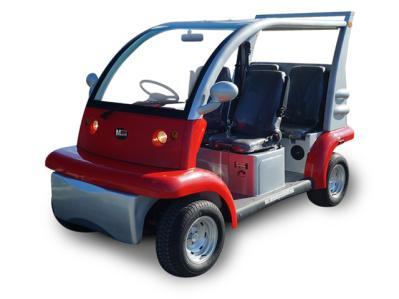


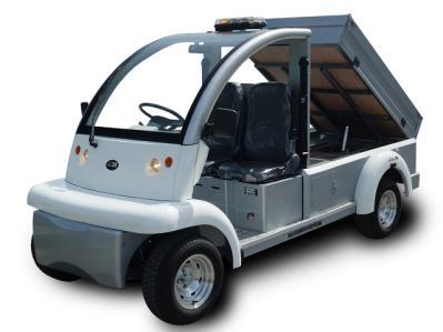
1 58 West 9 th Street Atlantic Beach, FL (904) CustomerSupport@MotoElectricVehicles.com MotoEV Bubble Car Owners Manual Pictures for Reference: 1


2 INDEX 1. Overview Page 3 2. Operating Instructions Page 5 3. Controls Page 6 4. Operation Page Maintenance Page Main Trouble and troubleshooting Page Lubrication Page Periodic Maintenance Charts Page Storage Page END OF DOCUMENT Page 24 2


3 1. Overview WARNING! Please make sure you have checked with the local authorities on where your new low speed vehicle can be used! Moto Electric Vehicles is not responsible for knowing you local laws; please make sure you look into this before using your new vehicle! IMPORTANT LABELS SAFETY LABEL Read carefully and understand the contents on the safety label attached on the vehicle. Safety labels on 03 style vehicle Safety label on 02 style vehicle Label content of the safety labels Fig. 1 3


4 Fig.2 \ Fig.3 4


5 Vehicle Information (Name Plate) The name plate is at the lower part of the dashboard as in the below picture: Chassis number of the vehicle: See Picture below to view the Chassis Number: 2. Operating Instructions The MotoEV Bubble Car has a very simple design for operation. Please carefully read the below operation procedures to have a successful experience with the vehicle! BEFORE OPERATING: ALWAYS read this first before you start driving the vehicle. ONLY authorized people should drive this vehicle. DO NOT OPERATE WHEN SITTING IN THE PASSENGER SEAT. Drive the vehicle ONLY in areas where the vehicle is allowed by law or local regulations and under safe conditions. DO NOT overload the vehicle! If this vehicle is overloaded the motor could become overloaded as well resulting in failure. DO NOT climb any slope over 20% grades. 5

6 Do not operate this vehicle in sand or mud, this will damage the motor. WHILE OPERATING THE VEHICLE Keep your entire body inside the vehicle, keep seated and hold on while the vehicle is moving. Do not start the vehicle until all occupants are securely seated. Keep your hands on the steering wheel and your eyes on road. Always back up slowly, and watch behind the vehicle carefully. Avoid starting or stopping suddenly. Avoid turning the steering wheel too sharply at higher speed. 3. Controls 1) Schematic Figure of controls (Please note there was a Chassis Design Change Made in We have listed the SE and LE dash controls for reference. Please Follow the Chassis Design Below that matches your vehicle) LE DESIGN (2012 AND AFTER) 6


7 SE DESIGN (2012 AND BEFORE) 2) Functions of Controls Power key The power key is used to switch on the electrical system of the vehicle. To engage the motor and start the vehicle, Insert the key and turn it clockwise to the ON position, at the same time, the 12V accessory system (including the headlight, 7


, a Buzzer will activate which warns pedestrians and vehicles behind the")


8 turn signal, taillight, brake light and horns) will be engaged too. To switch the power off, turn the key counterclockwise to OFF position. CAUTION! When the Key is on ON position, the key cannot be pulled out. Don t try to pull out the Key when it s on ON position! Forward/reverse switch This is a three-position switch: Up Position: Forward Middle Position: Neutral Down Position: Reverse WARNING! This switch must be fully pressed into the proper position. If not, the electrical system/motor could become faulty. NOTE: When the F/R Switch is in the Down Position (Reverse), a Buzzer will activate which warns pedestrians and vehicles behind the vehicle. Accelerator pedal The accelerator pedal is used to control the speed when driving. When pressing down the accelerator pedal, the vehicle will start to move. Letting off the accelerator pedal will cause the vehicle to slow down. Please note regenerative braking is included on this vehicle. Regenerative Braking will activate when the driver takes his/her foot off the accelerator pedal. Service Brake pedal The service brake pedal is used in braking. SE DESIGN LE DESIGN Parking Brake Pedal The parking brake pedal is used in when the vehicle is being parked. The parking brake should be engaged into parking position whenever the vehicle is left unattended. How to engage and disengage the parking brake? 8


9 LE To engage the parking brake Fig. 1 Step down the parking brake pedal by foot until it s hooked Fig 2. Step down upper section of the parking pedal by foot until it s hooked. SE To disengage the parking brake, Fig. 1 Step down the parking brake pedal to the end until the parking brake pedal is unhooked. Fig. 2 Step down lower section of the parking to the end until parking brake pedal is unhooked. WARNING! Please always disengage the parking brake pedal before you drive the vehicle. Failure to do this can cause damage to the braking system of the vehicle. Steering wheel The steering wheel is used to control the driving direction. Please avoid any sudden movements which can cause the vehicle to flip. TOW/RUN SWITCH (available for Curtis 1268 controller) Before operating the vehicle, make sure the TOW/RUN switch is on RUN position. Make sure the TOW/RUN switch is on the TOW position if towing the vehicle. The TOW/RUN switch is located under the dashboard as showed below picture. LE SE NOTE: When the TOW/RUN switch is on the RUN position, the vehicle will beep if towing the vehicle. TURN THE VEHICLE TO TOW MODE RIGHT AWAY IF YOU HEAR THIS BEEP COMBINATION SWITCH: Combination switch includes a left lever and a right lever: the left lever of the switch is used to switch on/off the lighting system including the headlights, front turn signals, rear turn signals, and the taillights; the right lever is used to control the wiper and horn. *NOTE: The Combination Switch is NON Canceling, please return the Turn Signal Stick to the Neutral Position when done turning! 9
 Turn the top button to power on the headlights and taillights; and turn back to power off the headlights and taillights.")


10 LE SE Left lever: It s used to control the lights including headlights, taillights and turning lights. 1) Turn the top button to power on the headlights and taillights; and turn back to power off the headlights and taillights. 2) Push the lever up to engage the right turning lights 3) Push the lever down to engage the left turning lights Right lever It s used to control the wiper and horn Wiper switch: This switch is used to control windshield wiper. LE SE Horn Switch: Press the top button of the lever to activate the horn. Emergency Light Switch the emergency light switch is located near the digital dashboard. Press the button down to turn the Emergency Flashers on. Turn the Button to the upper position to shut it off. DIGITAL DASHBOARD: 10
.")
 Disengage the parking brake pedal. CAUTION!")
11 LE SE Speedometer / Odometer--- Speedometer- Shows the current speed of the vehicle Odometer- Show the current distance the vehicle has traveled. Amperemeter Indicate the current running through the vehicle at the current time. Battery Power Meter There are 10 divisions on the meter (from 0 to 1). The meter will decline from the top to the bottom as the battery discharges. When the battery is too low, the red indicator light will flash, reminding you to recharge the battery. NOTE: please refer to your Battery Charger Owner s Manual to know how to recharge the batteries. 4. Operation STARTING: a) Disengage the parking brake pedal. CAUTION! Failure to disengage the parking brake when driving the vehicle will cause motor the burn up! 11
12 b) With the Forward/Reverse switch on the Neutral position, turn the power key to ON position. CAUTION! The car will not run if if the F/R Switch is not in the neutral position when an AC Motor is installed. Please make sure to start the vehicle in the Neutral Position to have a successful experience. c) Press the Forward/Reverse switch to lock the vehicle into the desired position. WARNING! Do not shift from Forward to Reverse or from Reverse to Forward when the car is moving. d) Step down on the acceleration pedal slowly; the vehicle will start to move. STOPPING: To stop the vehicle, gradually press down the brake pedal. When the vehicle has come to a stop, apply the parking brake pedal and turn the power key to the OFF position and press the F/R switch to the Neutral position. CAUTION: When on an incline, do not use the accelerator pedal to stop the vehicle. Please use the brake to avoid any damage to the batteries and motor. PLEASE WEAR SAFETY BELTS AT ALL TIMES IF PROVIDED 5. Maintenance Users should perform regular maintenance to the vehicle to keep the performance at an acceptable manner. MAINTENANCE OF BATTERY NOTE: Our Vehicles are equipped with deep-cycle flooded lead-acid batteries. If your vehicle is equipped with other types of batteries (AGM or Sealed Gel Batteries), please follow the maintenance instructions by the battery manufacturer. The below maintenance instructions relate to deep-cycle flooded lead-acid batteries. WARNING! Battery electrolyte is extremely poisonous and may cause severe burns and injury. Always wear protective clothing, gloves, and goggles when doing battery maintenance. KEEP OUT THE REACH OF CHILDREN. 1) Cleaning a. The Exterior of al the batteries should be kept clean. The Battery Cables and Battery terminals should also be cleaned on a constant basis. When cleaning, please make sure all battery vent caps 12
13 are tightly in place. Clean the top of the battery with a cloth or brush. Baking Soda and Water can be used along with a cloth. When cleaning the batteries please make sure the cleaning solution doesn t gets inside the batteries. This should be done every week. b. Cleaning the battery cable clamps (ends of the battery cable) is important! Use a bristle brush to remove any corrosion present. After cleaning, the ends should have a metallic shine to it. Constantly check for corrosion when inspecting the battery cables. c. Reconnect the clamps to the terminals of the batteries and thinly coat them with petroleum jelly (Vaseline) to prevent corrosion. WARNING! Before you disconnect any battery cable from any terminal on the battery, please always remove the power by disconnecting the main battery cable from the controller. 2) Checking the terminals and nuts The connection of the battery should always be kept in good condition. Please check the battery cables every week and make sure the battery cable terminal/nut has not come loose. Checking the battery cable nuts will prevent the cables from burning. If any burnt cables are present, replacement is needed. 3) Recharging a. Moto Electric Vehicles recommends plugging in your vehicle every time the vehicle is not being used. The Lead Acid Batteries do not have a memory so the end user does not have to fully discharge the vehicle to then charge it. When the vehicle is not in use, plug the vehicle in. The vehicle should be charged daily. b. If the vehicle is not going to be used daily it is best to leave the charger plugged in. Moto Electric Vehicles uses a smart charger that will turn itself on/off. c. When the vehicle is in motion, the driver will notice the battery fuel gauge will adjust and start to diminish. It is the driver s responsibility to monitor this gauge on the dash. When the battery charge is starting to get to the bottom of the gauge, it is best to get to an outlet and charge the vehicle. Brining the charge extremely low is not good for the batteries and can cause issues with the charger charging the batteries. WARNING! During recharging, the vehicle should be parked in a well-ventilated area with the battery filling caps tightly secured. When charging, keep the vehicle away from any fumes or fire to prevent explosion. Moto Electric Vehicles is not responsible for the location of the vehicle and where the end user decides to charge the vehicle. 5) WATERING Flooded batteries need distilled water. Watering must be done at the right time and in the right manner. If done in the wrong manner, the battery s performance and longevity will suffer. Distilled water should always be added after fully charging the vehicle. Prior to charging, there should be enough water to cover the plates in the batteries. If the battery has been discharged (partially or fully), the water level should be above the plates. NOTE: Depending on the local climate, charging methods, and application, etc., Trojan recommends that the end user checks the batteries once a month. 13
14 Important things to remember: 1. Do not expose the plates in the batteries to the air. Keep the Fluid Caps on the batteries at ALL times. 2. Do not fill the water to the top of the cell tube. This will cause the acid to flow outside of the battery, causing it corrode the terminals, leading to a failure of the battery. 3. Do not use water with a high mineral content. Use distilled or demonized water only. CAUTION: The electrolyte is a solution of acid and water so skin contact should be avoided. Step by step watering procedure: 1. Open the vent caps and look inside the filling wells. 2. Check electrolyte level; the minimum level is at the top of the plates. 3. If necessary add just enough water to cover the plates. 4. Put batteries on a complete charge before adding water (refer to the Charging section). 5. Once charging is completed, open the vent caps and look inside the fill wells. 6. Add water until the electrolyte level is 1/8" below the bottom of the fill well. 7. A piece of rubber can be used safely as a dipstick to help determine this level. 8. Clean, replace, and tighten all vent caps. WARNING! Never add acid into the battery. 6) TESTING Visual inspection alone is not sufficient to determine the overall health of the battery. Both open-circuit voltage and specific gravity readings can give a good indication of the battery's charge level, life span, and health. Routine voltage and gravity checks will not only show the state of charge but also help spot signs of improper care, such as undercharging and over-watering, and possibly even locate a bad or weak battery. The following steps outline how to properly perform routine voltage and specific gravity testing on batteries. I. Specific Gravity Test (Flooded batteries only) 1. Do not add water. 2. Fill and drain the hydrometer 2 to 4 times before pulling out a sample. 3. There should be enough sample electrolyte in the hydrometer to completely support the float. 4. Take a reading, record, and return the electrolyte back to the cell. 5. To check another cell, repeat the 3 steps above. 6. Check all cells in the battery. 7. Replace the vent caps and wipe off any electrolyte that might have been spilled. 8. Correct the readings to 80 o F: Add.004 to readings for every 10 o above 80o F, Subtract.004 for every 10 o below 80 o F. 9. Compare the readings. 10. Check the state of charge using Table 1. 14
 on a complete charge. 3. Take specific gravity readings again. If any specific gravity readings still register low then follow the steps below. 1. Check voltage level(s). 2.")
15 The readings should be at or above the factory specification of / If any specific gravity readings register low, then follow the steps below. 1. Check and record voltage level(s). 2. Put battery(s) on a complete charge. 3. Take specific gravity readings again. If any specific gravity readings still register low then follow the steps below. 1. Check voltage level(s). 2. Perform equalization charge. Refer to the Equalizing section for the proper procedure. 3. Take specific gravity readings again. If any specific gravity reading still registers lower than the factory specification of /-.007 then one or more of the following conditions may exist: 1. The battery is old and approaching the end of its life. 2. The battery was left in a state of discharge too long. 3. Electrolyte was lost due to spillage or overflow. 4. A weak or bad cell is developing. 5. Battery was watered excessively previous to testing. Batteries in conditions 1-4 should be taken to a specialist for further evaluation or retired from service. II. Open-Circuit Voltage Test For accurate voltage readings, batteries must remain idle (no charging, no discharging) for at least 6 hrs, preferably 24 hrs. 1. Disconnect all loads from the batteries. 2. Measure the voltage by a DC voltmeter. 3. Check the state of charge with Table Charge the battery if it registers 0% to 70% charged. If the battery value is lower than that in Table 1, the following conditions may exist: 1. The battery was left in a state of discharge too long. 2. The battery has a bad cell. Batteries in these conditions should be taken to a specialist for further evaluation or retired from service. 15
16 TABLE 1. State of charge as related to specific gravity and open circuit voltage Percentage of Charge Specific Gravity Corrected to 80 o F Open-Circuit Voltage 6V 8V 12V 24V 36V 48V ) Battery installation WARNING! When working with the battery, DO NOT put wrenches or any other metal objects across the battery terminals, otherwise, an arc can occur, and it may cause explosion of the battery and physical injury. Batteries should be installed or replaced only by a qualified electrician. 8) BATTERY CHARGING FOR CHARGING INSTRUCTIONS, PLEASE VISIT THE CHARGING MANUAL: CLICK HERE Common Mistakes with Charging: Dedicated 20 AMP Outlet is needed to Charge the Vehicle. Please make sure the Outlet is not shared with any other devise. The Vehicle should be the only devise plugged in Heavy Duty Extension Cords are to be used with these chargers. Please do not use a low rated gauge cord. Do not leave the vehicle unplugged for long periods of time. This will cause the charger to not recognize the battery pack. If this happens, a force charge cycle will need to be done. DO NOT OPEN THE CHARGER FOR ANY REASON, THIS WILL VOID THE WARRANTY DO NOT CUT THE PLUG ADAPTER FOR ANY REASON, THIS WILL VOID THE WARRANTY 16
17 DO NOT REMOVE THE YELLOW WARRANTY LABEL, THIS WILL VOID THE WARRANTY. Maintenance of the Traction DC Motor 1) For DC motors, the carbon brush should be checked every 6 months to see if there has been any excessive wear. If it is not replaced in time before it is worn out, it will damage the motor badly. 2) Removal of mud, sand and other clinging objects shall be done frequently to facilitate the heat-radiation. 3) Periodically use low pressure air to remove the dust from the carbon brush and the commutator. Periodically check the connections of the carbon brush and the commutator. Main malfunction and possible reason of DC motor Item Symptoms Possible Causes 1 All copper plates turn black. The pressure of brush is incorrect. 2 The commutating copper turns black in a certain order and in groups. 3 The commutating copper turns black. 4 The brush wears out, changes colors and breaks. Short circuit happens between the commutating copper or among the armature coil; poor welding or disconnection happens between the commutating copper and the armature coil. The central line of the commutator deviates or its surface is not round and not smooth. The motor vibrates; the clearance between the brush and its holder is too big; the clearance between the brush and commutator is too big; the mica between the different commentators extrudes; the brush is made from the wrong materials; the brush type is wrong. 5 Sparking From Motor The motor is over-loaded; the commutator is not clean, not round or not smooth; mica or some commutator extrude; the brush is not grounded properly; the brush is big in pressure; the brush is not the right type; the brush is jammed in the brush holder; the brush holder became loose or is vibrating; the polarity and sequence of magnetic poles is wrong. 6 The brush and its wires get hot. Big sparks from the brush; poor contact between brush and soft wires; small section area of soft wires. 7 The brush is noisy The surface of the commutator is not smooth. Caution: Only a Qualified Electrician Can Change And Adjust The Carbon Brush And Commutator. Maintenance of the Traction AC Motor 17
18 If your vehicle is equipped with AC motor, then the motor is maintenance free! Maintenance of the Controller: CAUTION Only a qualified electrician is allowed to do the maintenance for the controller. WARNING! Do not open the controller for any reason. Moto Electric Vehicles does not sell internal components for the controller. If the controller becomes faulty, a new controller is needed. Opening the controller will void the warranty on the controller. CLEANING It is recommended to keep the controller clean at all times. The fault history should be checked and cleared periodically. Please use the following cleaning procedure for routine maintenance: 1) Turn the power key to the OFF position. 2) Remove power by disconnecting the battery. 3) Discharge the capacitors in the controller by connecting a load (such as a contactor coil or a horn) across the controller s B+ and B- terminals. 4) Remove any dirt or corrosion from the connector areas. The controller should be wiped clean with moist rag. Dry it before reconnecting the battery. The controller should not be subjected to pressured water flow from either a standard hose or a power washer. 5) Make sure the connections are tight, but do not over tighten them. Faulty History File The handheld programmer (to be ordered separately) can be used to access the controller s fault history file. The programmer will read out all the faults the controller has experienced since the last time the history file was cleared. Faults such as contactor faults may be the result of loose wires; contractor wiring should be carefully checked. Faults such as over temperature may be caused by operator habits or by overloading. After a problem has been diagnosed and corrected, it is a good idea to clear the fault history file. This allows the controller to accumulate a new file of faults. Please note that the Curtis brand of controllers have a flashing light on the outside of the controller. These flashing lights can be translated to fault codes if a hand held is not present. Please look up the model of controller your cart has online for the service manual. The controller service manual will container the fault code readings. Trouble-Shooting Guide (For Series System): Symptoms The vehicle cannot be started. Possible Causes A. The controller has no power; a. There is something wrong with the battery or wire connections. b the fuse of the power connection is burnt; c the resistance for pre-charging is broken. 18
19 The vehicle can only move forward and cannot be reversed, or vice versa The vehicle can only run at slow speed B. No signal is transmitted to the controller: a. The power key is damaged or its wiring might be disconnected. b. There is something wrong with acceleration pedal c. The polarity diode is broken or has short cut. d. The green wire connecting the acceleration pedal and the controller KSI is disconnected; C. The contacting point of the contactor is stuck. D. The controller of the motor is damaged. a. The switch is damaged. b. The inserts on the commutators is loose. c. The commutators are damaged. a. Insufficient Battery; b. Handbrake is engaged or brake shoe is faulty. c. Accelerator Defect; d. Controller Defect Trouble Shooting Guide (For SEPEX System) Please refer to Troubleshooting Chart of Curtis SEPEX controller. Please contact your local dealer or a qualified electrician to work on the problems related to the motor, controller or electrical system of the vehicle when you are not able to fix them. Maintenance of Rear Axle: 1) Clean any dust or debris daily that can cause any harm to the rear axle. 2) Make sure all the connections are in good condition and tight. 3) Periodically check the gear oil in the rear end; if low please add gear oil. 4) Check to see if there is any play in the connection/ gear units. Please note a small bit of play is okay. 5) Check the brake drum on the rear of the cart. If the temperature if hot to the touch or a burning smell is present, please adjust the brake right away. 6) Check if the breather valve to ensure an oil leak is not present. 7) Check the parking brake cables to make sure they are intact. If not, replace immediately. 6. Main Trouble and troubleshooting Symptom(s) Possible cause(s) Troubleshooting The axle housing gear or bearing are damaged and there is too much noise when driving the vehicle. 1. The gear oil is low/wrong gear oil was used 2.The bearing is not adjusted properly 3. Adjust the brake shoe pin shim or the interval. 4.The gear between axle 1 and 2 is not a tight fit 19 Add Gear Oil or Replace Gear Oil Adjust Bearing Adjust or replace Adjust accordingly
20 5. The final drive is too noisy: Check to see if the gear is damaged. Replace the gear Low Braking Force 6.Axle 1 strikes strongly 7.The rear axle is out of shape(check if it is over loaded) 1. There is an interval between the brake shoes and drum. 2. There is oil or dirt on the Brake Shoes or Drum 3.There is air in brake pipes 4. The brake pipe leaks. Adjust or replace Replace the rear axle Adjust the interval Remove Debris from Component. Check and Make Sure the Wheel Cylinder is not Faulty. Bleed the Brakes Repair the leakage or change the brake pipe 5. The brake shoes are worn. Replace Brake Shoes The brake is Sticking/Stuck 6. The brake cable is too long or is stuck. 1.The brake pedal cannot disengage smoothly 2.The brake shoe is out of line 3.The is a blockage at the transmission Adjust the brake cable or Replace Replace Refit or replace Refit or replace Oil Leaks 1.The Oil Seal is damaged 2.Too much Oil Replace a new one Adjust the oil level Wheel Replacement WARNING! Before doing anything to the wheel and tire, please make sure the power key is positioned to the OFF position. Protect your face and eyes from escaping air when removing the valve core. Be sure the mounting/demounting machine is anchored to floor. Wear safety equipment when mounting/demounting the wheel and tire. To remove a wheel on the vehicle: (Jack Not Included) 1) Use a jack to lift the vehicle. Loosen Wheel Nuts and Remove the wheel from the Hub. 20
 in 20ft.lbs.(30Nm) increments following the cross sequence pattern 3) Remove the jack.")
21 To install a wheel on the vehicle: 1) Use a jack to lift the vehicle. Put the wheel onto the wheel hub and add lug nuts. 2) Finger tighten the lug nuts, then tighten lug nuts to 50-85ft.lbs.(70-115Nm) in 20ft.lbs.(30Nm) increments following the cross sequence pattern 3) Remove the jack. If the tire is flat, remove the wheel and inflate the tire to the maximum recommended pressure for the tire. Immerse the tire in water to locate the leak and mark with chalk. Place tire plug according to the manufacturer s specifications. Brake Adjustment 1 step down on the brake pedal with a force of 66 lbs or so, keeping the vehicle at a speed of 2/3 its max speed 2The clearance for the brake plate is self-adjusting. Under a force of around 44 lbs, the parking brake handle should be fixed in one gear from 5 to 10 ratchets. When the parking brake handle is released completely, the brake function will stop. 3 Inspect and/or change the brake shoes. Add lubrication into the brake bearing periodically if needed. Before you operate the vehicle, please press down on the brake pedal several times to make sure the brakes are functioning properly. 7. Lubrication 1 Use 901 car brake oil DOT3 as brake oil; 2 Use 1L of 90GL hypoid gear oil for the rear axle; 3 Lubrication points (use butter): a. steering gears; b. middle shaft; c. horizontal bars; d. steering ball joints; e. bearings; 21


22 Rear End Steering Gear Middle shaft 8. Periodic Maintenance Charts Regular maintenance is required for the best performance and safe operation of this vehicle. WARNING! Make sure to turn off the power key and apply the parking brake when doing maintenance. If the owner is not comfortable doing the maintenance; a local dealer should be consulted to do the work. 1D per day 1W per week 1M per month 1Q per quarter 1Y per year item Descriptions 1D 1W 1M 1Q 1Y Battery 1. Check the liquid level. Please add the distilled Y water if necessary. 2. Charge the battery Y 3. Tighten the nut on the battery cable Y 4. Check to see if the batteries are severely Y discharged. (the battery power meter flashing) 22
23 Charger Controller Motor Chassis and body 5. Check the liquid density of the battery, standard Y density should be 1.277±0.007g/ cm 3 (80 o F. or 25 ) when the battery is fully charged. 6. Check if the battery is charged fully Y 7. Clean the surface of battery Y 8. Observe the charging status, check if the charger Y plug becomes hot. 9. Clean the surface of the charger. Do not get any Y water inside the charger. 10. Check if all terminals are tightened properly. Y Please do this with the power off. 11. Clean the surface of the controller. Y 12. Check if the solenoid is working properly, Y checking the connections. 13. Check to make sure the motor is not too hot. Y Check to make sure water didn t enter the motor. 14. Check if the carbon brush should be replaced. Y 15. Check if the accelerator pedal works well and Y doesn t stick. 16. Check if the brake drum and the brake shoes Y should be replaced or not. 17. Check if the hand brake functions well. Y (Applicable for vehicle with hand brake). 18. Check for leaks at the brake fluid Y tank.(applicable for vehicle with hydraulic brake). 19. Check to see if the brake fluid needs to be filled. Y (Applicable for vehicle with hydraulic brake). 20. Check the air pressure inside the tire. Check for Y any wearing of the tire. 21. Check the shocks for any oil leaks or noise. Y 22. Check for any oil leaks at the rear end. Y 23. Add the lubricant inside the wheel hubs and Y steering system. 24. Adjust the toe-in of the front end Y 25. Clean the body and seat Y 9. Storage Please follow the steps as below when the vehicle is stored. 1. Check the liquid level inside the batteries; recharge the vehicle fully before storing the vehicle. WARNING! Please keep your vehicle s charger plugged in at all times. We use a smart charger that will turn on/off when a charge is needed. Not plugging in your vehicle for a long period of time will result in low voltage and failure of the batteries. 23
24 2. Turn the power key to the OFF position, remove the key, and store the key in a safe place. 3. Move the tow switch into the TOW position. (Switch located under Dash) 4. Check the tire pressure to make sure all the tire s pressure is set to the recommended pressure. 5. Clean the exterior of the vehicle and apply a rust inhibitor. 6. Cover the vehicle with a breathable cover and store it in a dry, safe and well-ventilated place. 7. If you plan to not use the vehicle within 30 days, please make sure to monitor the liquid levels in the batteries and keep the charger plugged in! 58 West 9 th Street Atlantic Beach, FL (904) CustomerSupport@MotoElectricVehicles.com 24
citecar Bubble Buddy Owner s Manual
 citecar Bubble Buddy Owner s Manual Sold and Distributed by citecar LLC www.citecarev.com Phone: (866) 542-8677 Fax: (843) 556-4080 1 Preface Thanks for purchasing our electric vehicle. This manual contains
Owner s Manual and Service Guide
 Owner s Manual and Service Guide C Series: AC48-2-AC-UB-L-D and AC48-2-AC-UB-S-D Thanks for buying the Star EV C-Series. For better use, please read through this manual before operating this vehicle to
Operation Manual for Electric Golf Car
 Operation Manual for Electric Golf Car Thanks for purchasing our electric golf cars. This manual contains information for proper operation and maintenance and care of your golf car. A thorough understanding
Proper Torque Values for Connection Hardware. 90 to 100 in-lbs
 Introduction Trojan Battery Company has been manufacturing lead-acid batteries for more than three generations. Our experience has shown that the key factor to achieving optimum performance and long battery
citecar Street Legal Golf Cart Owner s Manual Sport Edition
 citecar Street Legal Golf Cart Owner s Manual Sport Edition Sold and Distributed by citecar LLC www.citecarev.com Phone: (866) 542-8677 Fax: (843) 556-4080 1 Preface Thanks for purchasing a citecar electric
citecar Street Legal Golf Cart Owner s Manual
 citecar Street Legal Golf Cart Owner s Manual Sold and Distributed by citecar LLC www.citecarev.com Phone: (866) 542-8677 Fax: (843) 556-4080 1 Preface Thanks for purchasing a citecar electric vehicle.
Owner s Manual and Service Guide
 Owner s Manual and Service Guide Roadster-2+2, Roadster-4+2, Roadster-6+2 August 2014 Table of Contents Specifications 2 Operation Vehicle layout 3 Dashboard 3 Switches 4 Pedals 5 Charging 5 Cigarette
Owner s Manual and Service Guide
 Owner s Manual and Service Guide Roadster: Roadster 2+2-AC and Roadster 4+2-AC Thanks for buying the Star EV Roadster. This manual contains information you will need for proper operation, maintenance,
15Amp Intelligent Battery Charger Suitable for SLA, Gel, Maintenance Free, AGM, Deep Cycle batteries
 15Amp Intelligent Battery Charger Suitable for SLA, Gel, Maintenance Free, AGM, Deep Cycle batteries MB-3622 READ THESE INSTRUCTIONS BEFORE USE AND RETAIN FOR FUTURE REFERENCE! 1 CAUTION! When working
Deep Cycle Battery Safety. First. Battery Handling, Maintenance & Test Procedures
 Deep Cycle Battery Safety. First. Battery Handling, Maintenance & Test Procedures Crown deep cycle batteries employ a low-maintenance design. They do require periodic maintenance and effective charging
Cargo Truck. Owners Manual
 .. Cargo Truck Owners Manual 1 Preface Thank you for choosing PET Cargo Truck manufactured by Wooking Electric Vehicles Co., Ltd. Please read this manual carefully before using the product to enjoy optimized
Owner s Manual and Service Guide
 Owner s Manual and Service Guide ACcel-2-DC and ACcel-2-AC May 2014 Notes: Only authorized persons should be allowed to operate the vehicle. It is recommended that the only persons allowed to operate the
Automatic Battery Charger Switching mode with Micro-controlled Input: Vac / Output: 12Volt DC
 Automatic Battery Charger Switching mode with Micro-controlled Input:100-140Vac / Output: 12Volt DC User s Manual and Important Safety Information Model: #20085 (SW121080-06) FEATURES Congratulations on
ACCUSENSE CHARGE SERIES ON/OFF BOARD FULLY AUTOMATIC BATTERY CHARGER
 ACCUSENSE CHARGE SERIES ON/OFF BOARD FULLY AUTOMATIC BATTERY CHARGER SPECIFICATIONS: *Photo for reference only* Part number 8890439 Mode Select: Selects Battery Type Refer to Section 6. IMPORTANT: READ
Service Manual. Extractor Model XR28QP. For The. For: Troubleshooting Adjustments
 Service Manual For The X Ride 28 Rider Extractor Model XR28QP For: Training Troubleshooting Adjustments Contents 1 Cautions ------------------------------------------------------------------------------
Car Battery Charger Instructions for Use
 BATTERY CHARGER 12Volt 4Amp FOR INDOOR USE ONLY Power Details: Input: 230-240Vac; 50Hz; 52W Output: 12V DC; 2.8A Maximum Charge Rate: 4A RMS Read these instructions before operating this car battery charger
User Manuel. Titan Hummer XL
 User Manuel Titan Hummer XL Dear User, Tzora Active Systems Ltd. thanks you for choosing the Titan Hummer-XL and wishes you safe and enjoyable journeys. For proper operation and to maintain the scooter
Operator Manual. The most important component is you. This operator manual. has information for. all models of series. B plus some options and
 Operator Manual This operator manual has information for all models of series B plus some options and accessories. Some of the illustrations and information may not apply to your truck. The most important
SERVICE INFORMATION BATTERY/CHARGING SYSTEM XL CHARGING SYSTEM INSPECTION 15-5 REGULATOR/RECTIFIER 15-6 ALTERNATOR 15-7
 15. BATTERY/CHARGING SYSTEM SERVICE INFORMATION 15-1 TROUBLESHOOTING 15-2 BATTERY 15-3 CHARGING SYSTEM INSPECTION 15-5 REGULATOR/RECTIFIER 15-6 ALTERNATOR 15-7 SERVICE INFORMATION GENERAL t The battery
QSSE, QSSEX INDUSTRIAL Battery Chargers
 C O R P O R A T IO N O P E R A T I N G I N S T R U C T I O N S QSSE, QSSEX INDUSTRIAL Battery Chargers INTRODUCTION The QSE line are electronically controlled float chargers. The batteries are brought
Sport Ice 240E Elektro. Operation Manual
 Sport Ice 240E Elektro Operation Manual Small Machines. Big Performance. Great Ice. 1 Introduction: The Sport Ice 240E Elektro is a compact ice resurfacing machine designed to be used on small ice surfaces.
MP V 8A Electronic Smart Charger. Instruction and Information Manual
 MP7428 12V 8A Electronic Smart Charger Instruction and Information Manual In order to ensure correct and safe usage of your battery charger, you should read these instructions carefully. Please retain
ELECTRIC PALLET TRUCK
 π H-3405 ELECTRIC PALLET TRUCK 1-800-295-5510 uline.com GENERAL SAFETY GUIDELINES WARNING! Do not operate this truck unless you have been trained to use it, authorized to do so and have checked it is in
AIR COMPRESSOR OPERATING INSTRUCTION AND PARTS LIST
 AIR COMPRESSOR OPERATING INSTRUCTION AND PARTS LIST BELT TYPE IMPORTANT PLEASE MAKE CERTAIN THAT THE PERSON WHO IS TO USE THIS EQUIPMENT CAREFULLY READS AND UNDERSTANDS THESE INSTRUCTIONS BEFORE STARTING
BRAKE SYSTEM Return To Main Table of Contents
 BRAKE SYSTEM Return To Main Table of Contents GENERAL... 2 BRAKE PEDAL... 10 MASTER CYLINDER... 13 BRAKE BOOSTER... 16 BRAKE LINE... 18 PROPORTIONING VALVE... 19 FRONT DISC BRAKE... 20 REAR DRUM BRAKE...
User s Manual. Automatic Switch-Mode Battery Charger
 User s Manual Automatic Switch-Mode Battery Charger IMPORTANT Read, understand, and follow these safety rules and operating instructions before using this battery charger. Only authorized and trained service
QPET, QPETXU Battery Chargers
 C O R P O R A T IO N O P E R A T I N G I N S T R U C T I O N S QPET, QPETXU Battery Chargers INTRODUCTION: The QPET line of chargers are designed for general purpose deep cycle batteries. They are an electronically
Towing and Road Service Guide For The 2010 Lexus HS250H. Quality and Education Services AAA Automotive 1000 AAA Drive Heathrow, FL 32746
 Towing and Road Service Guide For The 2010 Lexus HS250H Quality and Education Services AAA Automotive 1000 AAA Drive Heathrow, FL 32746 October 7, 2009 Index General Vehicle Information Major Component
PowerLevel s e r i e s
 Owner s Manual Hydraulic Leveling CONTENTS Introduction Operation Control Panel Automatic Leveling Manual Leveling Retracting Jacks Remote Operation Care & Maintenance Troubleshooting Error Codes 1 2 2
OBE, OBEXU, ON BOARD Battery Chargers
 C O R P O R A T IO N O P E R A T I N G I N S T R U C T I O N S OBE, OBEXU, ON BOARD Battery Chargers INTRODUCTION: These chargers are designed for the permanent installation on battery powered vehicles
Today, we re going to talk about battery safety. We ll discuss all the key issues associated with using batteries safely, including battery hazards,
 Today, we re going to talk about battery safety. We ll discuss all the key issues associated with using batteries safely, including battery hazards, battery charging, and battery maintenance. Although
CHAPTER 10 ELECTRIC SYSTEM
 CHAPTER 10 ELECTRIC SYSTEM 1. ELECTRIC SYSTEM ELECTRIC SYSTEM 1.1 WIRING DIAGRAM CK20-USA 196WA00A S196-WOO Jul. 2003 10-3 CK20(M) CHAPTER 10 CK20-EU 196WA51A 10-4 S196-WOO Jul. 2003 ELECTRIC SYSTEM 1.2
HIGH FREQUENCY AUTOMATIC BATTERY CHARGER
 HIGH FREQUENCY AUTOMATIC BATTERY CHARGER MODEL NO: HFBC12 PART NO: 6267000 OPERATION & MAINTENANCE INSTRUCTIONS LS0814 INTRODUCTION Thank you for purchasing this CLARKE High Frequency Automatic Battery
Automatic Battery Charger Switching mode with Micro-controlled Input: Vac / Output: 12Volt DC
 Automatic Battery Charger Switching mode with Micro-controlled Input:220-260Vac / Output: 12Volt DC User s Manual and Important Safety Information Model: OC-SW121080 / OC-SW121160 / OC-SW121210 FEATURES
Operator Manual. This operator manual has. information for all models. of series M plus some. options and accessories. Some of the illustrations
 M S E R I E Operator Manual S This operator manual has information for all models of series M plus some options and accessories. Some of the illustrations and information may not The most apply to your
Motive Power. Network Power. Chargers. Bloc Batteries. Accessories. Service
 The Eternity Technologies range is built using only the highest quality and most efficient production processes at our state-of-the-art manufacturing centre in the UAE. It is this innovation, modern design
Troubleshooting the Transmission Hydraulic System
 Testing and Adjusting IT28F INTEGRATED TOOLCARRIER POWER TRAIN Testing And Adjusting Introduction Reference: For Specifications with illustrations, refer to SENR5974, IT28F Integrated Toolcarrier Power
Automatic Battery Charger Switching mode with Micro-controlled Input: Vac / Output: 12Volt DC
 Automatic Battery Charger Switching mode with Micro-controlled Input:220-260Vac / Output: 12Volt DC User s Manual and Important Safety Information Model: OC-SW121080 / OC-SW121160 / OC-SW121210 FEATURES
SBC / 2140 / Stage Battery Charger User Manual
 SBC - 2130 / 2140 / 2150 3 Stage Battery Charger User Manual Keep this manual in a safe place for quick reference at all times. This manual contains important safety and operation instructions for correct
Motive Power. Network Power. Chargers. Bloc Batteries. Accessories. Service
 The Eternity Technologies range is built using only the highest quality and most efficient production processes at our state-of-the-art manufacturing centre in the UAE. It is this innovation, modern design
7 Stage Automatic Smart Battery Charger (FOR CHARGING 12V / 24V AGM, GEL,SLA AND WET BATTERIES) USER MANUAL
 USER MANUAL") 7 Stage Automatic Smart Battery Charger Desulphuration& Maintainer (FOR CHARGING 12V / 24V AGM, GEL,SLA AND WET BATTERIES) USER MANUAL THIS MANUAL CONTAINS IMPORTANT SAFETY AND OPERATING INSTRUCTIONS 1
7 Stage Automatic Smart Battery Charger Desulphuration& Maintainer (FOR CHARGING 12V / 24V AGM, GEL,SLA AND WET BATTERIES) USER MANUAL THIS MANUAL CONTAINS IMPORTANT SAFETY AND OPERATING INSTRUCTIONS 1
Electric motor testing
 Electric motor testing MOTOR (MODELS EJ4-4001 AND EJ8-4001A) 23 GENERAL INFORMATION The vehicle is equipped with a 48-volt DC, shunt-wound, reversible traction motor. The shunt-wound motor is designed
BC12M248 7 Stage Automatic Smart Battery Charger, Desulfator & Maintainer 12V, 2 / 4 / 8A FOR AGM, GEL AND WET BATTERIES USER MANUAL
 BC12M248 7 Stage Automatic Smart Battery Charger, Desulfator & Maintainer 12V, 2 / 4 / 8A FOR AGM, GEL AND WET BATTERIES USER MANUAL THIS MANUAL CONTAINS IMPORTANT SAFETY AND OPERATING INSTRUCTIONS 1 IMPORTANT
Models: SP3, SPSS3 Automatic Battery Charger
 OWNERS MANUAL Models: SP3, SPSS3 Automatic Battery Charger PLEASE SAVE THIS OWNERS MANUAL AND READ BEFORE EACH USE. This manual will explain how to use the charger safely and effectively. Please read and
Maxx-Mini Lift MMLE-50D Service Manual
 Maxx-Mini Lift MMLE-50D Service Manual LIFT PRODUCTS INC PO BOX 349 ELM GROVE WI 53122 262-521-5720 FAX 262-521-5725 Toll Free 877-543-8776 Model: MMLE-50D S/N Customer REGISTRATION INFORMATION (To validate
SP6. Automatic Battery Charger. Model
 Model SP6 Automatic Battery Charger OWNERS MANUAL PLEASE SAVE THIS OWNERS MANUAL AND READ BEFORE EACH USE. This manual will explain how to use the charger safely and effectively. Please read and follow
WEBER CARBURETOR TROUBLESHOOTING GUIDE
 This guide is to help pinpoint problems by diagnosing engine symptoms associated with specific vehicle operating conditions. The chart will guide you step by step to help correct these problems. For successful
8 Step Fully Automatic Intelligent BATTERY CHARGER 12V 5A USER S MANUAL. Charges & Maintains. Flooded (WET), MF, VRLA, AGM, GEL & Calcium batteries
, MF, VRLA, AGM, GEL & Calcium batteries") 8 Step Fully Automatic Intelligent BATTERY CHARGER 12V 5A Charges & Maintains Flooded (WET), MF, VRLA, AGM, GEL & Calcium batteries USER S MANUAL 5 User s Manual And Guide To Professional Battery Charging
8 Step Fully Automatic Intelligent BATTERY CHARGER 12V 5A Charges & Maintains Flooded (WET), MF, VRLA, AGM, GEL & Calcium batteries USER S MANUAL 5 User s Manual And Guide To Professional Battery Charging
Towing and Road Service Guide For The Lexus CT200h. Quality and Education Services AAA Automotive 1000 AAA Drive Heathrow, FL 32746
 Towing and Road Service Guide For The Lexus CT200h Quality and Education Services AAA Automotive 1000 AAA Drive Heathrow, FL 32746 January 4 th, 2011 1 Index General Vehicle Information Major Component
FULLY AUTOMATIC SCR BATTERY CHARGER
 *35589* FULLY AUTOMATIC SCR BATTERY CHARGER FEATURES Microprocessor controlled charge circuit monitors battery state of charge and automatically turns charger off when the batteries reach full charge.
NILFISK BA 500 Service Manual
 NILFISK BA 500 Service Manual Model 66324400 12/94 Form Number 043023 TABLE OF CONTENTS Batteries...21 Brush Drive Belt Adjustment Or Replacement...7 Brush Drive Motor - Carbon brush Inspection... 8 Brush
ivacuum 34 Operating instructions (ENG) CV34X Read these instructions before using the machine T 02/09/12
 CV34X Read these instructions before using the machine T 02/09/12") ivacuum 34 Operating instructions (ENG) MODELS: CV34 10125650 CV34X 10125790 Read these instructions before using the machine. 86347810-T 02/09/12 Machine Data/Overview OVERVIEW The Chariot ivacuum 34
ivacuum 34 Operating instructions (ENG) MODELS: CV34 10125650 CV34X 10125790 Read these instructions before using the machine. 86347810-T 02/09/12 Machine Data/Overview OVERVIEW The Chariot ivacuum 34
ANTI-LOCK BRAKE SYSTEM
 ANTI-LOCK BRAKE SYSTEM 1993 Mitsubishi Diamante 1993 BRAKES Mitsubishi - Anti-Lock Brake System Diamante DESCRIPTION The Anti-Lock BRAKE SYSTEM (ABS) is designed to prevent wheel lock-up during heavy braking.
EnergyCell FLA Series. Owner s Manual
 Series Owner s Manual About OutBack Power Technologies OutBack Power Technologies is a leader in advanced energy conversion technology. OutBack products include true sine wave inverter/chargers, maximum
Light condition and operation Windshield glass condition Wiper blade condition Paint condition and corrosion Fluid leaks Door and hood lock condition
 GENERAL CHECKS Engine Compartment The following should be checked regularly: Engine oil level and condition Transmission fluid level and condition Brake fluid level Clutch fluid level Engine coolant level
WARRANTY WILL BE VOID If These Steps are Not Performed Before Installing The Control STEPS TO PERFORM BEFORE CONTROL INSTALLATION
 Curtis 1268-5411 This sheet is provided to aid in the installation of your remanufactured CURTIS controller. Upon installation, you may encounter problems that may, or may not, be due to a faulty controller.
STARTING/CHARGING SYSTEMS Brought to you by Eris Studios NOT FOR RESALE
 STARTING/CHARGING SYSTEMS General Description 1. General Description A: SPECIFICATION Vehicle model Starter Generator Item Specification Type Reduction type Model 428000-5760 Manufacturer DENSO Voltage
BATTERY CHARGER-STARTER
 BATTERY CHARGER-STARTER MODEL NO: WBC240 & WBC400 PART NO: 6261505 & 6261515 OPERATION & MAINTENANCE INSTRUCTIONS GC0116 INTRODUCTION Thank you for purchasing this CLARKE Battery Charger/Starter. Please
1.CONTENTS 1. Contents Control location Before riding Safe riding Driving Use genuine spare parts Use
 1.CONTENTS 1. Contents... 1 2. Control location... 3 3. Before riding... 4 4. Safe riding... 4 5. Driving... 5 6. Use genuine spare parts... 5 7. Use of each component... 6 Gauges... 6 Operation of ignition
CONTENT. 3. Maintenance
 CONTENT Foreword -------------------------------------------------------------------------------------------- 1 1. The performance, technical parameters and structure of Go Kart--------------------------------------------2
AUTOMATIC BATTERY CHARGER AUTOMATISCHES BATTERIELADEGERÄT CHARGEUR DE BATTERIE AUTOMATIQUE AUTOMATISCHE ACCULADER 12A RMS (8A DC) MCH12A
 MCH12A") AUTOMATIC BATTERY CHARGER AUTOMATISCHES BATTERIELADEGERÄT CHARGEUR DE BATTERIE AUTOMATIQUE AUTOMATISCHE ACCULADER 12A RMS (8A DC) MCH12A Suitable for all type of 12V lead acid, sealed, leisure and gel
AUTOMATIC BATTERY CHARGER AUTOMATISCHES BATTERIELADEGERÄT CHARGEUR DE BATTERIE AUTOMATIQUE AUTOMATISCHE ACCULADER 12A RMS (8A DC) MCH12A Suitable for all type of 12V lead acid, sealed, leisure and gel
OBAE, OBAEXU, ON BOARD Battery Chargers
 C O R P O R A T IO N O P E R A T I N G I N S T R U C T I O N S OBAE, OBAEXU, ON BOARD Battery Chargers INTRODUCTION: The OBAE line of chargers are designed for the permanent installation on battery powered
CORPORATION REPAIR MANUAL HWH SPACEMAKER ROOM EXTENSION SYSTEM NO LEVELING SYSTEM FOR NATIONAL RV NON-MOTORIZED VEHICLES
 HWH R CORPORATION REPAIR MANUAL HWH SPACEMAKER SYSTEM NO LEVELING SYSTEM FOR NATIONAL RV NON-MOTORIZED VEHICLES FEATURING: DUAL CYLINDER "RAIL" (WITH RACK SENSING VALVE) SINGLE CYLINDER DUAL CYLINDER "RAIL"
SECTION 5 MAINTENANCE
 SECTION 5 Maintenance requirements................................ 166 General maintenance..................................... 167 Does your vehicle need repairing?......................... 170 Scheduled
OWNERS MANUAL Models: XP400, XP500, XP750C INSTANT POWER Jump Starter and DC Power Source
 OWNERS MANUAL Models: XP400, XP500, XP750C INSTANT POWER Jump Starter and DC Power Source XP400 XP500 XP750C PLEASE SAVE THIS OWNER S MANUAL AND READ BEFORE EACH USE. This manual will explain how to use
IMPORTANT SAFETY INSTRUCTIONS
 1163714 1.5 AMP 12VOLT TRICKLE 1.5 AUTOMATIC AMP AUTOMATIC TRICKLE 1.5 AMP AUTOMATIC 12V12VOLT BATTERY CHARGER IMPORTANT SAFETY INSTRUCTIONS 1. SAVE THESE INSTRUCTIONS This product offers a wide range
SECTION 6 3 SERVICE PROCEDURES AND SPECIFICATIONS. Chassis
 SERVICE PROCEDURES AND SPECIFICATIONS Chassis SECTION 6 3 Specifications........................................... 208 Checking brake fluid...................................... 210 Checking power steering
12 amp RMS Battery Charger
 12 amp RMS Battery Charger 83-5000-12 If faults cannot be remedied, contact the Helpline on 020 8391 6767 helpline@hilka.co.uk Manufactured under license by Hilka Pro Imports GUARANTEE This product is
COLLECTOR 37 USER MANUAL
 COLLECTOR 37 USER MANUAL A B E F C D H 2 G ENGLISH INTRODUCTION POWERBOSS,Inc. leaders in the production of sweeping machines, are pleased to welcome you as an owner of the Collector 37 sweeper machine.
Towing and Road Service Guide For The Lexus ES300h. Quality and Education Services AAA Automotive 1000 AAA Drive Heathrow, FL 32746
 Towing and Road Service Guide For The Lexus ES300h Quality and Education Services AAA Automotive 1000 AAA Drive Heathrow, FL 32746 September 7, 2012 1 Index General Vehicle Information Major Component
Battery. Charger Model: Save Important Safety Instructions
 Owner's Manual Battery Charger Model: SS-51A-PE, 10 Amp Fully Automatic Battery Charger For 12 Volt Marine Deep Cycle & Automotive Batteries Save Important Safety Instructions Read Rules for Safe Operation
Owner and Operating Manual for
 Owner and Operating Manual for 120VAC Manual Control 12VDC Solar Battery Manual Control 120VAC Remote Control 12VDC Solar Battery Remote Control GEN2 Remote Versions Only Boat Lifts Please read this manual
PSJ-2212, PSJ-3612, PSJ-4424
 Model: PSJ-2212, PSJ-3612, PSJ-4424 Jump Starter and DC Power Source OWNER S MANUAL PSJ-2212 PLEASE SAVE THIS OWNER S MANUAL AND READ BEFORE EACH USE. This manual will explain how to use your jump starter
Starting and Charging
 The Starting and Charging System is a critical system in your vehicle. The Starting system provides the ability to crank the engine electrically from the drivers position. The first car with electric starting
Retriever 4600 OPERATOR MANUAL Advance MODEL
 Retriever 4600 OPERATOR MANUAL Advance MODEL 56416000 9/97 revised 7/00 Form Number 56041389 TABLE OF CONTENTS Page Introduction...2 Parts and Service...2 Nameplate...2 Uncrating the Machine...2 Cautions
Typical Install Instructions
 Typical Install Instructions Read & understand all steps of these instructions before beginning this installation. WEBER Conversion Kit, VW T-1/2, up to 1835cc 32 / 36 DFEV Weber Carburetor These instructions
12 VOLT 30 AMP DIGITAL SOLAR CHARGE CONTROLLER
 12 VOLT 30 AMP DIGITAL SOLAR CHARGE CONTROLLER User s Manual Congratulations on your Coleman solar product purchase. This product is designed to the highest technical specifications and standards. It will
Model: SE-4020-CA Automatic Battery Charger
 OWNERS MANUAL Model: SE-4020-CA Automatic Battery Charger PLEASE SAVE THIS OWNERS MANUAL AND READ BEFORE EACH USE. This manual will explain how to use the battery charger safely and effectively. Please
ELECTRICAL BATTERY/STARTING/CHARGING SYSTEMS DIAGNOSTICS
 Z ELECTRICAL 8A - 1 ELECTRICAL GROUP INDEX page AUDIO SYSTEMS... 8F BATTERY/STARTER/GENERATOR SERVICE... 8B BATTERY/STARTING/CHARGING SYSTEMS DIAGNOSTICS... 8A CHIME WARNING/REMINDER SYSTEM... 8U HORNS...
Operation Guide. Operation Guide. Winnebago Hydraulic Leveling Systems by Kwikee. Introduction. Table of Content WARNINGS
 Operation Guide 05/07 Kwikee #1422192 Rev. 0F Table of Content Page Introduction 1 Safety Information 1 Operation 2 Control Panel 3 Manual Leveling 3 Automatic Leveling 3 Remote Operation 4 Stabilizing
Electric Car User Manual
 Electric Car User Manual The owner s manual contains important safety information as well as assembly, use and maintenance instructions. The Ride-on Car must be assembled by an adult who has read and understands
SRT OPERATIONS MANUAL
 MAINTENANCE SECTION PAGE # VEHICLE DAILY INSPECTION.......................................1 P.M. INSPECTION #1.................................................3 P.M. INSPECTION #2.................................................6
FUM-24xxCBP Series 3 Stage Battery Charger User Manual
 FUM-24xxCBP Series 3 Stage Battery Charger User Manual Keep this manual in a safe place for quick reference at all times. This manual contains important safety and operation instructions for correct use
Turbo M Series onboard charger
 Turbo M Series onboard charger Operation Manual Model # Output Bank Max. Output Turbo M106 1 6 Amps Turbo M108 1 8 Amps Turbo M208 2 8 Amps Turbo M212 2 12 Amps Turbo M220 2 20 Amps Turbo M230 2 30 Amps
17. BATTERY/CHARGING SYSTEM
 17 17 BATTERY/CHARGING SYSTEM CHARGING SYSTEM LAYOUT/CHARGING CIRCUIT ----------- 17-1 SERVICE INFORMATION------------------------------------------------ 17-2 TROUBLESHOOTING-----------------------------------------------------
PW Operator Manual PW This operator manual. has information for all. models of series PW plus some options. and accessories.
 Operator Manual PW 3000 S E R I E S This operator manual has information for all models of series PW 3000 plus some options and accessories. Some The most of the illustrations and important component information
BATTERY BOOSTER/CHARGER MODEL NO: DIGICAR 900
 BATTERY BOOSTER/CHARGER MODEL NO: DIGICAR 900 PART NO: 6261205 OPERATION & MAINTENANCE INSTRUCTIONS LS0715 INTRODUCTION Thank you for purchasing this CLARKE Battery booster / charger which is suitable
24 Volt - 3/8" Cordless Impact Wrench
 24 Volt - 3/8" Cordless Impact Wrench INSTRUCTION MANUAL Item # 3994040 IMPORTANT SAFETY INSTRUCTIONS WARNING: When using electrical equipment such as this, basic safety precautions should always be followed
User Manual GRX- 950 and GRX- 950 Li
 User Manual GRX- 950 and GRX- 950 Li Page 1 of 17 TABLE OF CONTENTS INTRODUCTION 3 BASIC SET- UP 4 TURNING ON YOUR GRX- 950 7 PRECAUTIONS 8 FREE WHEEL MODE 9 GENERAL BATTERY CARE 10 BATTERY INFORMATION
STARTING & CHARGING SYSTEM SECTIONSC CONTENTS IDX
 STARTING & CHARGING SYSTEM SECTIONSC GI MA EM LC EC CONTENTS FE PRECAUTIONS...2 Supplemental Restraint System (SRS) AIR BAG and SEAT BELT PRE-TENSIONER...2 Wiring Diagrams and Trouble Diagnosis...2 BATTERY...3
before serial number 2214
 before serial number 2214 Contents Page Safety Rules... 3 Pre-operational & Safety Inspection... 4 Operating Instructions... 6 Transport... 12 Maintenance & Routine Service... 12 Specifications... 14 SAFETY
EW-54. Owners Manual.
 EW-54 Owners Manual www.electricwheelstore.com Dear consumers, Foreword Welcome to the big family of Electric Wheels, and thank you for your choice of Electric Wheels electric tricycle! The electric tricycle
O P E R A T I N G I N S T R U C T I O N S
 O P E R A T I N G I N S T R U C T I O N S Select-A-Charge Battery Chargers models: SCP, SCPX, SCS, SCSX, SCX For Industrial Use: Designed for gel, wet cell, AGM, and Lithium Ion batteries (Lithium ion
ELECTRIC PALLET TRUCK
 π H-2302 ELECTRIC PALLET TRUCK 1-800-295-5510 uline.com OPERATING INSTRUCTIONS SAFETY GUIDELINES WARNING! Do not operate this truck unless you have been trained to use it, authorized to do so and have
INSTALLATION & OPERATION MANUAL
 INSTALLATION & OPERATION MANUAL PRE-ASSEMBLED PRIMARY & BATTERY BACK-UP SUMP PUMP SYSTEM 5030CVSPBUSS, 5033CVSPBUSS www.aymcdonald.com A.Y. McDonald BBU Manual Revised 8-13 3210-479 Rev. A 12 This pump
#9040 FUEL TANK SWEEPER
 #9040 FUEL TANK SWEEPER INSTRUCTION MANUAL FILTERS AND REMOVES FINE BIO-CONTAMINANTS, ALGAE, ETC. SWEEPING PROCESS REMOVES LARGE CONTAMINANTS FROM OIL TANKS SUCH AS RUST, WATER, CRUDE AND DIRT CIRCULATES
Lbs Kgs Ft M
 Installation Instructions for 92600 ATV Winch 3000 lb. Rated Pull SPECIFICATIONS Rated line pull: 3000 lbs. (1360kgs) single line Motor: Permanent magnetic DC 12V with 1.2 hp. /0.9kw output Gear: Differential
SCC-MPPT Solar Charge Controller
 Table 4: Alarm point for low battery voltage table Model Alarm point SCC-MPPT-300 10.5 V SCC-MPPT-600 21.0 V Table 5: Charging hour table for reference Battery Capacity To 90% capacity @ 25A charging current
TUFF TORQ TRANSAXLE. Tuff Torq Hydrostatic Transaxle. Transaxle Removal Tuff Torq
 Tuff Torq Hydrostatic Transaxle Internal Service 3. Disconnect the cotter pin and the washer to the brake rod (Figure 63). Internal service information is contained in the Tuff Torq KGIA Transaxle Service
WARNING. Electric Recovery Winch. General Safety Precautions
 1 Electric Recovery Winch Thanks for purchasing a WINCH. This manual covers operation and maintenance of the winch. All information in this publication is based on the latest production information available