2.1 Introduction. Chapter 2 Alternatives Considered
|
|
|
- Cleopatra Glenn
- 5 years ago
- Views:
Transcription
 for an approximately 18-mile extension of the Link light rail system, from")

1 Chapter 2 Alternatives Considered 2.1 Introduction This chapter describes the alternatives and how they were developed for study in this Final Environmental Impact Statement (EIS). The 2008 Draft EIS evaluated a No Build Alternative and 19 build alternatives within five segments (Segments A to E) for an approximately 18-mile extension of the Link light rail system, from Downtown Seattle to Redmond across the Interstate 90 (I-90) bridge. Since the 2008 Draft EIS was published, the Sound Transit Board has reviewed public and agency comments; added five additional alternatives and some design options to existing alternatives, most of which were analyzed in the 2010 Supplemental Draft EIS (SDEIS); and identified and refined the preferred alternatives for each segment. In response to the SDEIS, additional design options have been included and analyzed in this Final EIS. The alternatives described here meet the East Link Project purpose and need and include alternatives reviewed as part of the environmental review process as well as those eliminated from consideration. The evaluation processes that were used comply with guidelines of the National Environmental Policy Act (NEPA); the Washington State Environmental Policy Act (SEPA); and the Safe, Accountable, Flexible, and Efficient Transportation Equity Act A Legacy for Users (SAFETEA-LU). The proposed project consists of constructing and operating an approximately 18-mile light rail system known as East Link. This system would connect with Sound Transit s Central Link at the International District/Chinatown, and it then would travel east across Lake Washington via I 90 to Mercer Island, Downtown Bellevue, and Bel-Red/Overlake, terminating in Downtown Redmond. Exhibit 2-1 shows the five project segments and the 24 alternative routes with the proposed stations that are considered for detailed environmental review in this Final EIS. A No Build Alternative is also included to describe how the transportation system would operate if the proposed project were not built, thus serving to compare effects of the build alternatives. EXHIBIT 2-1 East Link Project Segments and Alternatives East Link Project Final EIS 2-1
2 The remainder of this chapter is organized into the following subsections: 2.2 Alternative Development and Public Scoping Process 2.3 Project Alternatives 2.4 Overview of Construction Approach 2.5 Environmental Commitments 2.6 Estimated Projects Costs and Funding 2.7 Next Steps and Schedule 2.2 Alternative Development and Public Scoping Process As stated in Chapter 1, the East Link Project and the alternatives considered in this document build on the conclusions of previous planning, studies, and public involvement processes dating back to the mid-1960s. In particular, the Sound Transit Board made the following major decisions after extensive evaluation and review with agencies and the public before beginning this EIS process: Regional high-capacity transit (HCT) to the Eastside via I 90 is necessary. Light rail is the selected HCT technology for the I-90/East Corridor connecting Seattle, Mercer Island, Bellevue, Overlake, and Redmond. Sound Transit s light rail alternatives development process for this Final EIS included the following steps: Identifying feasible alternatives Obtaining scoping comments on alternatives Conducting a detailed evaluation of refined alternatives Receiving input on the Draft EIS and SDEIS alternatives and responding with modifications and new alternatives for analysis For evaluation purposes, the East Link study area was divided into five segments along distinct geographic boundaries (see Exhibit 2-1). The five segments are as follows: Segment A, Interstate-90, travels from the Downtown Seattle Transit Tunnel (where the East Link Project would connect to the Central Link light rail system) to South Bellevue, where I 90 touches land in Bellevue. Segment B, South Bellevue, travels from where I 90 touches land in Bellevue to SE 6th Street, including the south boundary of Surrey Downs Park. Segment C, Downtown Bellevue, travels from SE 6th Street north to NE 12th Street, encompassing Downtown Bellevue and the area east of I-405 to the former BNSF Railway corridor. Segment D, Bel-Red/Overlake, travels from Downtown Bellevue (from the former BNSF Railway corridor or NE 12th Street) to the Overlake Transit Center at the intersection of NE 40th Street and State Route 520 (SR 520). Segment E, Downtown Redmond, travels from the Overlake Transit Center to Downtown Redmond, with three potential project terminus locations. The alternative evaluation process was also informed by an Inter-Agency Team that included the Washington State Department of Transportation (WSDOT); U.S. Army Corps of Engineers (USACE); Federal Transit Administration (FTA); Federal Highway Administration (FHWA); Cities of Seattle, Mercer Island, Bellevue, and Redmond; and King County. In addition, Sound Transit attended and presented information about East Link at neighborhood organizations, stakeholder gatherings, and upon request, city council and other board meetings. Refer to Appendix B for more detail Criteria for Evaluation The Sound Transit evaluation criteria were designed to satisfy the following project planning goals and supporting objectives as directed in the East Link Project purpose and need (see Chapter 1): Transportation goal: Improve transit mobility in the East Link corridor. Maximize East Link ridership. Improve the quality of transit service. Increase transit accessibility. Environmental goal: Preserve environmental quality. Minimize potential adverse operating impacts on the natural and built environments. Minimize potential adverse construction impacts on the natural and built environments. Land use goal: Support regional and local land use goals and objectives. Support adopted land use and transportation plans. 2-2 East Link Project Final EIS
3 Implementation goal: Minimize risk. Design system to reduce construction risk. Enhance stakeholder and community support. Financial goal: Provide a financially feasible solution. Build a system within project budget. Build a system that can be operated and maintained with available revenue. Build a system that is cost-effective Draft EIS Alternatives Identification To identify the most promising alternatives to propose during the public scoping process, Sound Transit developed 36 preliminary alternatives for the East Corridor between Seattle and the East Link growth centers of Bellevue, Overlake, and Downtown Redmond. In developing the preliminary alternatives, Sound Transit reviewed past planning studies in the corridor and consulted with state, federal, and local agencies in the corridor. Segment A included only the Interstate 90 Alternative (A1). Of the 35 alternatives in Segments B through E, Sound Transit, in consultation with the Inter-Agency Team, eliminated 9 alternatives based on the initial analysis because of ridership, cost, construction risk, and environmental impacts. Sound Transit recorded this process in East Link Alternatives Evaluation Report, Seattle to Bellevue to Redmond (Sound Transit, 2006c). Sound Transit advanced 27 alternatives and 5 potential maintenance facility locations for further evaluation. Sound Transit summarized the results of the evaluation in Sound Transit Board Briefing Book, Light Rail Alternatives (Sound Transit, 2006b), which was presented to the Sound Transit Board and posted on the project website ( This evaluation highlighted the results in the five comparative areas for all alternatives: Ridership: Additional systemwide boardings from adding East Link to Central Link were calculated. Environmental Impacts: Impacts were compared for relocations and impacts associated with parks, historic properties, traffic, noise, visual resources, ecology, and removal of parking and lanes, and construction disturbances on adjacent properties. Markets Served: Markets served are potential station areas with concentrations of employees and/or residents. Construction Risk: Risks were compared against an average risk of geologic and utilities constraints. Cost: The lowest cost alternatives in each segment were compared. Four maintenance facility sites were identified in Segment D and one in Segment E using the criteria of compatible land use zoning, relatively flat areas of approximately 15 acres, and convenient access to the light rail vehicles and tracks NEPA and SEPA Scoping Process The FTA and Sound Transit held a public scoping and comment period to officially initiate the NEPA and SEPA EIS process. The scoping period took place from September 1 to October 2, Sound Transit invited city and county agencies; affected tribes; regional, state, and federal agencies; interest groups; businesses; affected communities; individuals; and the public to comment on the proposed routes and stations, the environmental resources to be evaluated, and the project s preliminary Purpose and Need Statement. The public and agencies were asked to identify areas of concern, opportunities, and stakeholder interests to be further addressed in the subsequent EIS. During the scoping period, Sound Transit hosted four public scoping meetings and one scoping meeting for agencies and tribes. The public meetings were held in Seattle, Mercer Island, Bellevue, and Redmond. Oral and written comments were accepted. In addition, the public submitted comments directly by mail and . Details of the scoping and outreach activities can be found in Section B.4 of Appendix B, Public Involvement and Agency Coordination. Following this process, on December 14, 2006, the Sound Transit Board identified the alternatives to be evaluated in the Draft EIS. In December 2008, Sound Transit, WSDOT, and FTA published the East Link Project Draft EIS, which evaluated a No Build Alternative and 19 build alternatives Supplemental Draft EIS Alternative Identification After the 2008 Draft EIS was published, the Sound Transit Board reviewed public and agency comments, developed and evaluated new alternatives and design modifications, identified the preferred alternatives for each segment, and then revised the preferred alternatives while directing staff to include more alternatives for study. After the 2008 Draft EIS was published, the City of Bellevue proposed multiple new alternatives and design modifications. Sound Transit East Link Project Final EIS 2-3
4 has considered each of them, and some of the alternatives have been evaluated in joint studies with the City of Bellevue or other technical reviews. New alternatives were added to Segments B and C, and design modifications to alternatives previously studied in the Draft EIS were added in Segments B, C, D, and E. Sound Transit published the SDEIS in November 2010 to review the new alternatives and design modifications to existing alternatives that could result in substantial impacts not disclosed in the 2008 Draft EIS. To help develop the SDEIS, Sound Transit received input through the public process associated with three studies for project elements in Bellevue: the Downtown Bellevue Light Rail Alternatives Concept Design Report (Sound Transit and City of Bellevue, 2010a); the 112th Avenue Design Options Concept Design Report (Sound Transit and City of Bellevue, 2010b); and the Evaluation of Hospital Options (Sound Transit and City of Bellevue, 2010c). Sound Transit and the City of Bellevue cooperatively developed each study. Each study can be found in Appendix K of this Final EIS or found at Additionally, these studies are summarized in Appendix B, Public Involvement and Agency Coordination. The City of Redmond also held workshops and community outreach meetings that helped further define modifications to Segment D and E alternatives. The Downtown Bellevue Concept Design Report explored new at-grade and grade-separated alternatives in Downtown Bellevue, emphasizing traffic flow and cost trade-offs. The report evaluated six alternatives: two from the 2008 Draft EIS and four new alternatives; all new downtown alternatives studied were included in the SDEIS. Next, the Hospital and the 112th Avenue Design Options were explored with extensive public involvement from the community and interested stakeholders. This process reviewed three new locations for the Hospital, with optional access points to the hospital district, in addition to the one from the 2008 Draft EIS; the location from the 2008 Draft EIS was chosen to be carried forward. Along 112th Avenue SE, six at-grade and retained-cut profiles traveling in the center and on the east and west sides of 112th Avenue SE were studied. Information from the study and input from the community led the Sound Transit Board to identify the preferred alternative as the west side-running alignment along 112th Avenue SE north of SE 6th Street, which was considered in the SDEIS. In July 2010, the City of Bellevue requested that the Sound Transit Board consider new modifications to the BNSF Alternative (B7) and the Preferred 110th NE Tunnel Alternative (C9T), including a new South Bellevue adjacent to I-90 and a NE 2nd Street portal for the Preferred Alternative C9T tunnel. After the SDEIS was published, the City initiated a conceptual design and screening-level evaluation of these options or modifications to Alternative B7, referred to as B7- Revised ( B7R). A brief description of these options is provided following Segment C in Section of this chapter, and the results of the City s study are summarized in Section 7.6 of Chapter 7. The City of Bellevue s B7-Revised Interim Analysis Report (May 2011) can be found in Appendix K of this Final EIS Alternatives Eliminated Alternatives Eliminated During Screening After reviewing evaluation results and public and agency comments, the Sound Transit Board in December 2006 identified the alternatives to be analyzed in the Draft EIS. The Board eliminated eight alternatives and one maintenance facility site from further consideration, leaving 19 alternatives and 4 maintenance sites for review in the Draft EIS. The process of elimination is discussed below. Segment B In Segment B, three alternatives were eliminated, two of which traveled east along the south edge of Mercer Slough Nature Park and then turned north along the east boundary of the park adjacent to 118th Avenue SE. North of the park, the two alternatives diverged to follow different roadways. Sound Transit eliminated these alternatives because they would result in the highest environmental impacts along the Mercer Slough Nature Park and wetland areas, without providing any additional benefit compared to a remaining parallel alternative with lesser park impacts. The third alternative eliminated in Segment B had unnecessary out-of direction travel, resulting in higher costs and inefficiencies, without higher ridership than other alternatives in Segment B. This alternative traveled east, across the south edge of the Mercer Slough Nature Park, paralleling north of I-90, and turned north inside the former BNSF Railway corridor. This alternative then transitioned to parallel I-405, where the former BNSF Railway corridor continues east across I-405. At SE 8th Street, this alternative returned west to 112th Avenue SE, where it continued north. Segment C In Segment C, two alternatives were eliminated because of lack of available right-of-way at NE 7th Street. One alternative traveled along 110th Avenue NE and turned to cross over I-405 at approximately NE 7th Street, where there was thought to be 2-4 East Link Project Final EIS
5 inadequate separation between Meydenbauer Center and the newly constructed The Shops at Bravern. The other alternative followed 112th Avenue and transitioned to 110th Avenue NE via NE 4th Street before turning east at NE 7th Street. Again, there would be inadequate separation between Meydenbauer Center and the Shops at Bravern. Segment D Two alternatives in Segment D were found to result in excessive impacts along Bel-Red Road. One alternative traveled the length of Bel-Red Road from 124th to 152nd Avenue NE. The other traveled along NE 16th Street, a new planned roadway, then merged onto Bel- Red Road at 140th Avenue NE and continued to 152nd Avenue NE. Placing light rail in the median and widening the Bel-Red Road right-of-way would result in higher impacts on adjacent uses and greater construction and other environmental impacts. None of the remaining alternatives would travel along Bel- Red Road. Segment E Only one alternative was eliminated in Segment E. Segment E alternatives diverge from the same route at the SR 520 interchange with West Lake Sammamish Parkway. The alternative that was eliminated followed the south side of Bear Creek Parkway and traveled along several minor arterials up to the Bear Creek Park-and-Ride. This alternative was eliminated because it would have excessive impacts on ecosystems, parks, and traffic compared with other alternatives in Segment E. In addition, the Bear Creek Park-and-Ride location would present circulation and accessibility constraints related to adding a large terminus parking garage. Maintenance Facilities Five maintenance facility sites were considered, and only one, located near 136th Street NE in Segment D, was eliminated. Its location would have high environmental impacts and would limit transitoriented development potential near a potential station Alternatives Eliminated after the Draft EIS and SDEIS Comments on the 2008 Draft EIS resulted in a number of suggestions of new or previously studied alternatives, most of which have been eliminated from consideration for engineering, cost, and/or environmental issues. Specific responses to each letter and the suggestions are provided in Appendix J, Public and Agency Comments and Responses. The 112th Avenue Light Rail Options Concept Design Report evaluated six alternatives for connecting Preferred 112th SE Modified Alternative (B2M) with either Preferred 108th NE At-Grade Alternative (C11A) or Preferred 110th NE Tunnel Alternative (C9T), with a portal at either Main Street or NE 2nd Street. Those alternatives that were not carried forward were eliminated primarily due to noise, transportation, and/or construction impacts; cost; and/or community input. Sound Transit reviewed four Hospital options with the City of Bellevue and decided to carry forward the original alternative location based on criteria of optimizing station spacing, visibility, accessibility, and cost. The City of Bellevue also requested that Sound Transit examine two design modifications to the route east of the Bellevue Transit Center and east of I-405: (1) moving the route along NE 6th Street further south and (2) crossing underneath NE 8th Street east of I-405 before entering the Hospital. Both requests would affect the Preferred Alternatives C11A and C9T routes similarly. Shifting the route to the south side of NE 6th Street is not evaluated further because it would not reduce costs and would result in greater impacts on Bellevue City Hall and the King County Metro site redevelopment (located on the vacant lot next to the city hall building); it would require longer span structures over I-405 and 116th Avenue NE; and it would acquire an additional office building. Crossing underneath NE 8th Street is not evaluated further because it would increase costs by adding a tunnel and would push the Hospital location further north near NE 12th Street. This station location would have less desirable access, as demonstrated in the Evaluation of Hospital Options study and, due to the tunnel, would be approximately 30 feet below grade, resulting in higher cost and lower accessibility to riders. Comments on the 2010 SDEIS resulted in a number of suggested modifications to existing alternatives in order to avoid impacts to specific properties; these have not been included in the Final EIS because they generally would result in greater impacts to different properties, including parks, and potentially would increase other impact categories, such as noise, visual, and traffic. The East Link Project Final EIS addresses each suggestion in the response to comments (Appendix J). 2.3 Project Alternatives Following the alternatives evaluation process, Sound Transit identified a No Build Alternative, 24 build alternatives, and 4 maintenance facility alternatives to East Link Project Final EIS 2-5
6 carry forward to analyze in this Final EIS. This section describes each of these alternatives and the key project components that help to distinguish the alternatives. The Preferred Alternative is called out in italics to indicate the current preference identified by the Sound Transit Board. Identifying a Preferred Alternative in this Final EIS is a statement of the Board s current intent based on the input and analysis to date; it is not a final decision. Exhibit 2-2 illustrates the preferred alternatives in all segments: Segment A: Preferred Interstate 90 Alternative (A1) Segment B: Preferred 112th SE Modified Alternative (B2M) Segment C: Preferred 108th NE At-Grade Alternative (C11A) and Preferred 110th NE Tunnel Alternative (C9T) Segment D: Preferred NE 16th At-Grade Alternative (D2A) Segment E: Preferred Marymoor Alternative (E2) Sound Transit 2 Plan (ST2) provides funding for an atgrade or elevated alternative in Downtown Bellevue (Segment C); the Sound Transit Board would require additional funding sources in order to select a tunnel alternative in this segment. The Sound Transit Board identified two preferred alternatives in Segment C in April 2010: Preferred 108th NE At-Grade Alternative (C11A) and Preferred 110th NE Tunnel Alternative (C9T). Preferred Tunnel Alternative C9T is preferred based on a term sheet (a preliminary agreement) executed between Sound Transit and the City of Bellevue related to finding additional funding sources and scope reductions that would reduce the affordability gap for this tunnel alternative. Preferred Alternative C11A is preferred if additional funding and scope reductions cannot be found to afford the tunnel. Environmental review and preliminary engineering are funded for the portion of the East Link Project from the Overlake Transit Center to Downtown Redmond. While the final length and configuration of the constructed project would depend on project funding, final project design, track profiles, and project costs, this Final EIS covers the entire Seattle to Redmond East Link Project corridor. A separately bound document, Appendix G1, provides the detailed design drawings for each alternative. The East Link Project might be constructed in phases, depending on available funding and other factors. Sound Transit anticipates that any station including and east of the Hospital could be considered an interim terminus station. The minimum planned project would be to open East Link from Seattle to the Hospital in Bellevue (Segments A through C) No Build Alternative The No Build Alternative represents the transportation system and environment as they would exist without the proposed project. The No Build Alternative provides a baseline condition for comparing impacts of the build alternatives and includes two future transportation forecast years, 2020 and The No Build Alternative includes a variety of projects, funding packages, and proposals in the central Puget Sound region. The projects primarily consist of funded or committed roadway and transit actions by state, regional, and local agencies combined with other projects that are considered likely to be implemented based on approval and committed funding. The No Build Alternative includes completing the express bus, high-occupancy vehicle (HOV), and Transportation System Management projects described in Sound Move (Sound Transit, 1996) and also includes the Rapid Ride and other transit enhancements in the King County TransitNow Program (King County Metro, 2006). Table 2-1 summarizes roadway and transit projects that are included in the No Build Alternative. Appendix H1, Transportation Technical Report (Appendix A), details major projects assumed as part of this No Build Alternative. For the transportation analysis, there are two No Build Alternatives related to implementing the I 90 Two- Way Transit and HOV Operations Project (also referred to as the R-8A Project). The two variations in the No Build Alternative lie in implementing the I 90 Two-Way Transit and HOV Operations Project from Bellevue to Mercer Island to Seattle. Exhibit 2-3 illustrates how that project has been separated into three stages for funding purposes and describes what is included in each phase. The East Link Project would dedicate the I-90 center roadway for light rail use as stipulated in the 1976 Memorandum Agreement (and as amended in 2004; WSDOT, 2004) among Seattle, Mercer Island, Bellevue, King County Metro, and WSDOT. Today, the reversible center roadway is dedicated as HOV lanes traveling in the peak direction (Exhibit 2-4), and the outer roadways are general-purpose lanes. HOV lanes are being built on the outer roadways in three stages (Exhibit 2-5) so that HOVs can travel in both directions any time of the day. Funding for Stage 3 of the I-90 Two-Way Transit and HOV Operations Project is included in ST2. With ST2 approved, Sound Transit intends to work with WSDOT to complete Stage 3 and then close the center roadway for light rail conversion. 2-6 East Link Project Final EIS
7 To Lynnwood ¾À 908 ¾À 202 E2, Marymoor K i r k l a n d Downtown Redmond University of Washington SE Redmond R e d m o n d Lake Union ¾À 520 D2A, NE 16th At-Grade Overlake Transit Center Overlake Village Elliot Bay ¾À 99 International District/ Chinatown S e a t t l e Lake Washington A1, Interstate 90 M e d i n a C9T, 110th NE Tunnel C11A, 108th NE At-Grade C l y d e H i l l Bellevue Transit Center 108th SE 8th Hospital ¾À th 130th B e l l e v u e Lake Sammamish Rainier Mercer Island South Bellevue M e r c e r I s l a n d B2M, 112th SE To Sea-Tac Airport City Limits East Link Light Rail Alternatives East Link Segment Route Profile At-Grade Elevated Retained-Cut Retained-Fill Tunnel Link Light Rail Link Alignment and s N Mile Web/East_Link_Proj_Area_Alts_DEIS_ gr Exhibit 2-2 East Link Preferred Alternative East Link Project
/ transportation facility plans Comprehensive plans and transportation plans Puget Sound Regional Council Destination 2030")
8 TABLE 2-1 Components of No Build Alternative Roadway Project/Program Horizon Year Nickel Funding Package X X Approved 2003 Transportation Partnership Funding Package I-90 Two-Way Transit and HOV Operations Project Local Agencies Capital improvement plans (CIPs)/ transportation facility plans Comprehensive plans and transportation plans Puget Sound Regional Council Destination 2030 (including SR 520 between I-405 and Montlake Boulevard) Transit Sound Transit X X Approved 2005 Comments X X Stages 1 and 2, and with and without Stage 3 (see Exhibit 2-2) X X Typically 6-year (or near-term) funding commitments X X Typically 15- to 20-year list of funded and unfunded projects; funded projects included as part of CIP/transportation facility plan lists X Selected projects included Sound Move Program X X Approved 1996 ST2 Program X a X Approved November 2008; the package of projects is projected to be built by 2023 King County Metro Service Implementation Plans X X Transit Service Integration Plan X X Prepared for East Link Project Transit Now Plan X X Approved 2006 a Not all projects identified in this program are expected to be built by The Transportation Technical Report in Appendix H1 contains the project list by horizon year. EXHIBIT 2-3 Stages for Implementation of I-90 Two-way Transit and HOV Operations Project Alternative 2-8 East Link Project Final EIS

.")

9 EXHIBIT 2-4 I-90 Existing Conditions and No Build Alternative with I-90 Two-Way Transit and HOV Operations Project Stages 1 and 2 only In other words, the center roadway might close in order to construct the light rail project immediately after the HOV lanes on the outer roadway are completed, and the new HOV lanes in the outer roadway would never operate in conjunction with the center roadway. As a result, the No Build Alternative was analyzed with and without Stage 3 completion. Without Stage 3, HOV and transit travel between Mercer Island and Seattle would be restricted to the center reversible lanes in the peak direction only (i.e., westbound in the morning and eastbound in the evening). If Stage 3 were implemented, however, and began operating in conjunction with the center roadway before East Link construction begins, then both outer lanes of I-90 and the center reversible lanes would be available to transit and HOV. This variation in the lane configuration would only influence vehicle movements on I-90 and connecting transportation facilities Build Alternatives Light rail is a conventional term for urban electric rail systems that have the flexibility to operate along an exclusive right-of-way at ground level, on elevated EXHIBIT 2-5 I-90 No Build Alternative with I-90 Two-Way Transit and HOV Operations Project Stages 1, 2, and 3 structures, in subways, or in streets. Sound Transit plans for light rail consist of electrically powered, lowfloor, low-platform trains of up to four cars, with a total length of approximately 380 feet (90 feet per car, 96.5 feet per car with couplers), running on steel rails. The vehicles can carry as many as 200 passengers per car in the typical light rail car shown in Exhibit 2-6. East Link light rail would operate at speeds up to 55 miles per hour (mph) in a dedicated right-of-way and would generally not be constrained by congestion or accidents. The dedicated right-of-way might be in public roadway or in existing railroad or acquired right-of-way. The build alternatives are made up of a range of light rail routes and stations, with and without adjoining park-and-ride facilities. Maintenance facility alternatives are evaluated separately from the alternative routes and stations. Each build alternative is designed as a double-track rail system to accommodate planned project operational needs for uninterrupted light rail movement. The length of the entire East Link Project would vary between 17 and 19 miles, with up to 19 stations, depending on how the alternatives are combined. This section describes the EXHIBIT 2-6 Typical Light Rail Car East Link Project Final EIS 2-9
10 alternative routes and stations by segment. The alternatives have been developed to a conceptual engineering level of design (i.e., approximately 5 percent). Section describes the maintenance facilities, and detailed drawings are included in Appendix G1, Conceptual Design Drawings Components of Alternatives This section describes key components, such as the rail and station profile, to assist the reader in the understanding the alternatives. Other aspects of the project, including capital equipment and project operations, are described in Section 2.4. The proposed route and station alternatives vary in profile as traveling at-grade (sometimes a retained cut or a retained fill), in an elevated configuration, or in a tunnel. Maximum allowable grades for light rail are typically 5 to 6 percent. Because of the conditions along the corridor, the East Link Project is largely elevated or at-grade; however, tunnel alternatives were also considered in Downtown Bellevue (Segment C). At-grade operation is typically less costly, although each profile type has usefulness, as discussed in the following subsections. At-Grade Profile Light rail operating at-grade is best suited in areas where the grade is 5 to 6 percent or less and where there is adequate room within reserved street rightsof-way or off-street corridors. At-grade operation works well with a moderate number of riders and train frequencies as often as every 4 minutes. Where located within a street right-of-way, East Link at-grade routes travel either in the median or along the side of existing roadways (Exhibit 2-7) and operate through intersections with advance signal detection and prioritization. Retained Cuts and Retained Fills A variation of the at-grade profile is a retained cut or a retained fill. With a retained cut the trackway is cut into the ground with a retaining wall on one or both sides (Exhibit 2-8). With a retained fill the trackway is built up above the ground surface with a retaining wall on one or both sides. Exhibits 2-9 and 2-10 show possible retained fill profiles. Portions of the routes might involve retained cut or retained fill to meet train operation grade requirements or to separate the grade under heavily traveled roadways. Elevated Profile Light rail on elevated structures works well where the system must be grade-separated to cross over geographic or physical barriers and accommodate higher train frequencies and where at-grade trackway might not be appropriate for a surface corridor. Transitions between at-grade and elevated profiles are typically compacted fill support. An elevated profile must have a minimum clearance of about 16.5 feet near roadways, but topography and other consideration might result in a profile as high as 50 feet or more. Pier supports are typically approximately 10 feet by 10 feet square at the ground, although the support structure below the ground might be wider. Just as for at-grade routes, the elevated guideway can travel either in the median of existing roadways (Exhibit 2-11), along the side of the roadway (Exhibit 2-12), or in off-street corridors. Tunnels Tunnels might be used where slopes are steep (more than 5 to 6 percent), physical barriers must be crossed, right-of-way is inadequate for at-grade or elevated profiles, the density of homes and businesses is high, and/or ridership and resulting train frequencies would be so high as to make street-level operations impractical. They are also appropriate where major ridership areas cannot be served in another way. There are substantially greater costs and risks with building tunnels. The two most common construction methods are cut-and-cover or bored tunnels. Cut-andcover construction is built from the surface while bored (or mined) tunnels are constructed with no surface disturbance beyond entering and exiting the tunnel portals. The bored method is typically the most expensive. A cut-and-cover box and bored tunnel are shown in Exhibits 2-13 and s s are designed according to the alternative profile. Depending on the location, stations can be designed with center or side platforms. Center platforms allow passengers to access trains going in opposite directions from the same platform. Side platforms, much like a sidewalk on either side of a roadway, require the riders to cross over or under the tracks to access trains in the opposite direction. A station is typically 400 feet long to accommodate a four-car train but varies in width depending on the location of the platform and the profile. East Link stations would include pedestrian, bicycle, and bus access (with one exception) and may include paratransit access. All stations are Americans with Disabilities Act (ADA) accessible. In some cases, automotive access including park-and-ride lots and automobile drop off would be provided. Exhibit 2-15 illustrates four typical station designs: at-grade, elevated side platform, elevated center platform, and a tunnel station. The size of each station is determined by the site-specific access and parking requirements East Link Project Final EIS


11 EXHIBIT 2-7 At-Grade Center-Running EXHIBIT 2-8 Retained Cut EXHIBIT 2-9 Retained Fill, Center-Running EXHIBIT 2-10 Retained Fill, Side-Running EXHIBIT 2-11 Elevated Center-Running EXHIBIT 2-12 Elevated Side-Running East Link Project Final EIS 2-11


12 EXHIBIT 2-13 Cut-and-Cover Tunnel EXHIBIT 2-14 Bored Tunnel EXHIBIT 2-15 Typical Designs 2-12 East Link Project Final EIS
13 East Link stations would be designed to meet all local and federal accessibility requirements. At-grade stations would have passenger access walkways and ramps. Any elevated or tunnel station would be furnished with stairs, elevators, and, in some cases, escalators. Each station would have ticket vending machines, closed-circuit television, public address, emergency phones, and variable message signage. Additionally, tunnel stations would have systems that monitor and control ventilation and fire/life/safety functions. Interim Termini The East Link Project might be constructed in phases, depending on available funding and other factors. Sound Transit anticipates that any station including and east of the Hospital could be considered an interim terminus station. The minimum planned project would be to open East Link from Seattle to the Hospital in Bellevue (Segments A through C). If the East Link Project were built in phases, a station in Segment C or D would be selected as the interim terminus station. The Hospital or Ashwood/Hospital in Segment C or any Segment D station could serve as an interim terminus. The Overlake Transit Center in Segment D is identified as an interim terminus in ST2, because funding for constructing Segment E is not included in the plan. With any interim terminus station, a storage or tail track could be built beyond the station. The preferred location is a storage track in the former BNSF Railway north of the Hospital. If such a feature were built at an interim terminus station, then the project might also include parking for operators and office and storage space for light maintenance activities, such as cleaning interiors of vehicles. Railbanked Corridors Several of the build alternatives would use portions of the former BNSF Railway corridor. In 2008, the BNSF Railway Company filed a Notice of Interim Trail Use or Abandonment (NITU) with the Surface Transportation Board. This filing railbanked the right-of-way for interim trail use and keeps the rightof-way available for the reactivation of freight rail service. In addition to being the trail sponsor under the NITU, King County owns a trail easement over the former BNSF Railway right-of-way. In 2009, the Port of Seattle acquired the former BNSF Railway right-ofway from Snohomish to north Renton, including a spur from Woodinville to Redmond. The Port entered into a Memorandum of Understanding (MOU) with King County, the City of Redmond, Sound Transit, Puget Sound Energy, and the Cascade Water Alliance with regard to the Port s sale to the other parties of the Numbering of East Link Alternatives East Link Project alternatives are designated by either two or three characters: the segment letter (A, B, C, D, E), the number of the alternative, and, sometimes, a descriptive indicator consisting of A for at-grade, E for elevated, or T for tunnel. The letter M signifies modified from a previous Draft EIS alternative. For example, B2M indicates the second alternative in Segment B, and that it has been modified since the 2008 Draft EIS. C9A indicates the ninth alternative in Segment in C, and that it is an at-grade profile. A break in the numeric sequencing for the alternatives indicates that a previous alternative was eliminated in the alternative development process (see Section 2.2.5). former BNSF Railway right-of-way within King County. Sound Transit is in the process of acquiring 1.1 miles of this corridor in Segments C and D as well as an easement in other portions of the corridor potentially used by East Link. Sound Transit and the Puget Sound Regional Council (PSRC) have studied the feasibility of commuter rail service in the former BNSF Railway corridor. This study, published by Sound Transit in 2008, found that operating commuter/passenger rail in the former BNSF Railway corridor is feasible although a variety of capital improvements would be needed to accommodate higher speeds and to improve the safety of the track, structures, and roadway crossings in the corridor. The study also determined that a pedestrian/bicycle trail could also fit within the existing right-of-way throughout much of the corridor; however, in some locations, property acquisition would be required to accommodate commuter/passenger rail and a trail. Sound Transit is working with the MOU parties to plan for using the former BNSF Railway corridor while protecting the interim trail use and possible reactivation for freight rail. The corridor can accommodate both the trail (or a reactivated freight rail service) and the light rail route in most places, with some areas requiring a small right-of-way acquisition Description of Alternatives The route and station alternatives are described below, and their characteristics are summarized in Tables 2-2 and 2-3. Exhibits 2-16 to 2-20 show the alternatives by segment. The four maintenance facility alternative sites located in Segments D and E are described in Section and in Exhibits 2-19 and The alternatives are designated by letters and numbers that describe their location and nature, as described in the text box on this page. The types of tunnels for each alternative are discussed in Section 2.4.6, and stations are listed in the following alternative descriptions and summarized in Table 2-3. East Link Project Final EIS 2-13
14 TABLE 2-2 Characteristics of Light Rail Alternatives Alternative Segment Length (miles) a Segment Travel Time (minutes: seconds) a Number of s s Segment A, Interstate 90 Preferred Interstate 90 Alternative (A1) Rainier, Mercer Island Segment B, South Bellevue Preferred 112th SE Modified Alternative (B2M) To C11A South Bellevue To C9T South Bellevue, SE 8th b Bellevue Way Alternative (B1) South Bellevue 112th SE At-Grade Alternative (B2A) South Bellevue, SE 8th 112th SE Elevated Alternative (B2E) South Bellevue, SE 8th 112th SE Bypass Alternative (B3) 2.3 to South Bellevue BNSF Alternative (B7) th Segment C, Downtown Bellevue Preferred 108th NE At-Grade Alternative (C11A) 2.0 to to th, Bellevue Transit Center, Hospital Preferred 110th NE Tunnel Alternative (C9T) b 1.7 to to 3 East Main, Bellevue Transit Center, Hospital Bellevue Way Tunnel Alternative (C1T) Old Bellevue, Bellevue Transit Center, Hospital 106th NE Tunnel Alternative (C2T) 2.1 to to 3 East Main, Bellevue Transit Center, Hospital 108th NE Tunnel Alternative (C3T) 1.8 to to 3 East Main, Bellevue Transit Center, Ashwood/Hospital Couplet Alternative (C4A) 1.6 to to 11 2 to 3 East Main, Bellevue Transit Center, Ashwood/Hospital 112th NE Elevated Alternative (C7E) 1.4 to to 3 East Main, Bellevue Transit Center, Ashwood/Hospital 110th NE Elevated Alternative (C8E) 1.6 to to 3 East Main, Bellevue Transit Center, Ashwood/Hospital 110th NE At-Grade Alternative (C9A) to 9 2 to 3 East Main, Bellevue Transit Center, Hospital 114th NE Elevated Alternative (C14E) Bellevue Transit Center, Hospital Segment D, Bel-Red/Overlake Preferred NE 16th At-Grade Alternative (D2A) 3.3 to to 10 3 to 4 120th, 130th, Overlake Village, Overlake Transit Center NE 16th Elevated Alternative (D2E) 3.4 to to 4 120th, 130th, Overlake Village, Overlake Transit Center NE 20th Alternative (D3) 3.5 to to 4 120th, 130th, Overlake Village, Overlake Transit Center SR 520 Alternative (D5) Overlake Village, Overlake Transit Center Segment E, Downtown Redmond Preferred Marymoor Alternative (E2) 3.7 to to 3 SE Redmond, Downtown Redmond (Redmond Town Center, Redmond Transit Center) c Redmond Way Alternative (E1) Redmond Town Center, SE Redmond Leary Way Alternative (E4) Redmond Town Center, SE Redmond a Ranges are due to variation in length of connections from previous segment and design options considered. b Preferred Alternative C9T includes a design option (C9T - East Main Design Option) that, when connecting to Preferred Alternative B2M only, would have an East Main and eliminate Preferred Alternative B2M s SE 8th. c Preferred Alternative E2 includes a design option that would eliminate the Downtown Redmond and instead would have both the Redmond Town Center and the Redmond Transit Center s East Link Project Final EIS
15 H _TB SEA_East_LInk_DEIS_Maps/05-08/Seg_A_All_v4_ gr To University of Washington E MADISON ST NE 12TH ST NE 6TH ST 92ND AVE NE NE 8TH ST 100TH AVE NE B E L L E V U E 2-7 SEATTLE TUNNEL Segment A 1ST AVE S 4TH AVE S S SPOKANE ST BOREN AVE International District/ Chinatown AIRPORT WAY S S E A T T L E E CHERRY ST E YESLER WAY S JACKSON ST JUDKINS PARK AND PLAYFIELD BEACON AVE S 23RD AVE RAINIER AVE S Mt. Baker Tunnel Rainier SAM SMITH PARK LAKE WASHINGTON BLVD M L KING LAKE WASHINGTON BLVD I-90 Floating Bridge Lake Washington A1 I-90 Parks on the LID MERCER ISLAND PARK LID 72ND AVE SE W MERCER WAY 76TH AVE SE 77TH AVE SE Mercer Island 80TH SE Mercer Island Park & Ride LUTHER BURBANK PARK UPPER LUTHER BURBANK PARK SE 40TH ST SE 36TH ST M E R C E R I S L A N D GALLAGHER HILL OS E MERCER WAY MAIN ST Segment B Segment A BELLEVUE WAY SE JR WAY S To Sea-Tac Airport ISLAND CREST WY Preferred Alternative At-Grade Route Tunnel Route Other Alternatives At-Grade Route Tunnel Route A B Traction Power Substation Segment Limit Segment Limit Central Adjacent Link Alignment Segment and Central Link Alignment and N SCALE Mile Exhibit 2-16 Segment A, Interstate 90 East Link Project DRAFT For internal discussion only. Not reviewed or approved by or on behalf of any party.
16 123RD AVE SE H _TB SEA_East_Link_DEIS_Fall08/2-14_SegB_All_v5_ _fall08. gr Date: August 7, 2007 File Path: \\Bianca\Proj\SoundTransit\341526\GIS\MapDocuments\2007_06_DEIS\SpecialRequest\KickOff_0814\ALTERNATIVE_SegmentB_B1.mxd B1 104TH AVE SE BELLEVUE WAY SE B E L L E V U E Segment B, South Bellevue Preferred Alternative B2M 112th SE to C9T B2M 112th SE to C11A Other Alternatives B1 Bellevue Way B2A 112th SE At-Grade B2E 112th SE Elevated B3 112th SE Bypass B3 114th SE Design Option B7 BNSF SE 25TH ST Segment C Segment B B E A U X A R T S 108TH AVE SE 108TH AVE SE King County District Court House B2A B3 B2A B2E B3!!!!!!!!!!!!!!!!! BELLEVUE WAY SE B1 SURREY DOWNS PARK SE 8th B2A B2M to C11A B3 Mercer Slough West South Bellevue B2A B2E B3 112TH AVE SE SE 6TH ST B2E SE B2M to C9T B2M Frederick Winters House Mercer Slough East South Bellevue Park & Ride 8TH B3 Wilburton Park & Ride ST B3 114th Design Option MERCER SLOUGH NATURE PARK 118th B7 MERCER SLOUGH NATURE PARK B7 118TH AVE SE BNSF LAKE HILLS CONNECTOR RD 0 BNSF Kelsey Creek BNSF A B At-Grade Elevated Retained-Cut Traction Power Substation Segment Limit Profiles of non-preferred alternatives shown in gray. SCALE Mile Lake Washington Segment B Segment A B1 B2A B2E B3 B7 113TH AVE SE Mercer Slough East B2M B7 B1 MERCER SLOUGH NATURE PARK Preferred Alternatives At-Grade Route Elevated Route Retained-Cut Route Retained-Fill Route OtherAlternatives At-Grade Route Elevated Route Retained-Cut Route Retained-Fill Route A B Traction Power Substation New and/or Expanded Park-and-Ride Lot Segment Limit Adjacent Segment Source: City of Bellevue (2005) and King County (2006). Exhibit 2-17 Segment B, South Bellevue East Link Project 2-7 DRAFT For internal discussion only. Not reviewed or approved by or on behalf of any party.
17 108TH AVE SE 106TH AVE SE 112TH AVE NE H _TB SEA_East_Link_DEIS_Fall08/2-15_SegC_All_v3_ _fall08. gr July 30, 2007 File Path: \\bianca\proj\soundtransit\341526\gis\mapdocuments\2007_06_deis\specialrequest\kickoff_0814\alternative_segmentc_c1t.mxd Segment C, Downtown Bellevue Preferred Alternatives C9T 110th NE Tunnel C11A 108th NE At Grade Other Alternatives C1T Bellevue Way Tunnel C2T 106th NE Tunnel C3T 108th NE Tunnel C4A Couplet C7E 112th NE Elevated C8E 110th NE Elevated C9A 110th NE At Grade C14E 114th NE Elevated B E L L E V U E C1T DOWNTOWN PARK For C1T BELLEVUE WAY NE Old Bellevue NE 6TH ST NE 4TH ST C2T NE 2ND ST MAIN ST 108TH AVE NE For C1T C2T C4AC3T C4A C11A For C8E C8E C11A Bellevue Transit Center C3T C4A C9A For C3T C4A McCORMICK PARK ASHWOOD PARK 110TH AVE NE NE 12TH ST NE 10TH ST NE 8TH ST C7E For C1T C4AC2T Bellevue C7E Transit Center 112TH AVE NE For C8E C9T C8E C9T For C3T, C4A C7E, C8E Ashwood/ Hospital C9T C11A 114TH AVE NE For C8E Sturtevant Creek For C3T C3T C4A C7E C7E C8E NE 4TH ST C14E C1T C2T C9A C14E CONNECTORS 116TH AVE NE Segment D Segment C C1T C2T C9A C14E C9T C11A Hospital BNSF NE 12TH ST Lake Bellevue NE 8TH ST B C At-Grade Elevated Retained-Cut Retained-Fill Traction Power Substation Segment Limit Profiles of non-preferred alternatives shown in gray. C1T from B1 BELLEVUE WAY SE Segment C Segment B 108th C4A, C7E, 9A For from B2A C4A For C9T C1T East Main C2T, C3T Design Option C3T from B2A C2T from B2A King County For District C1T Court House C2T C3T C9T from B2M C11A from B2M SURREY C2T, C3T, C4A, C7E, C9A from B2E C2T, C3T, C4A, C7E, C8E, C9A, C9T, C11A, C14E from B3 East Main For C1T, C2T C3T, C4Alocation C7E, associated C8E with C8E only SE 6TH ST 116TH AVE SE C2T, C3T, C4A, C7E, C8E, C9A, C9T, C11A, C14E from B3 114th Design Option or B7 0 BNSF SCALE Mile DOWNS PARK Preferred Alternative At-Grade Route Elevated Route Retained-Cut Route Retained-Fill Route Tunnel Other Alternatives At-Grade Elevated Retained-Cut Retained-Fill Tunnel B C Traction Staging Power Area Substation Segment Limit Adjacent Segment New and/or Expanded Park-and-Ride Lot Segment Limit Source: City of Bellevue (2005) and King County (2006). Exhibit 2-18 Segment C, Downtown Bellevue East Link Project 2-7 DRAFT For internal discussion only. Not reviewed or approved by or on behalf of any party.
18 130TH AVE NE 2-7 BNSF 116TH AVE NE Storage Track CONNECTORS 120TH AVE NE 120th th Design Option 124TH AVE NE D5 NORTHUP WY Goff Segment D, Bel-Red/Overlake Preferred Alternative D2A NE 16th At-Grade Other Alternatives D2A 120th Design Option D2A NE 24th Design Option D2E NE 16th Elevated D3 NE 20th D5 SR 520 Creek B E L L E V U E MF3 134TH AVE NE VIEWPOINT PARK NE 24TH ST Valley Creek D2E D5 Sears Creek At-Grade Elevated Retained-Cut Retained-Fill Traction Power Substation C D Segment Limit GOLDSMITH Profiles NEIGHBORHOOD of non-preferred PARK alternatives shown in gray. D2A NE 24th Design Option NE 20TH ST Segment E Segment D D2E "Overlake Park & Ride!!!! R E D M O N D Overlake Village D5 151ST PL NE Overlake Transit Center 152ND AVE NE 520 D2A D2E D3 D5 Overlake Village NE 40TH ST! Overlake Transit Center 156TH AVE NE Segment D Segment C From C3T, C4A C7E, C8E MF1 NE 12TH ST MF2 120TH AVE From C1T, C2T D2A 120th NE West Tributary of Kelsey Creek D3 124TH AVE NE D2E D2A 130th 132ND AVE NE NE 16TH ST BEL-RED RD 136TH PL NE Kelsey Creek 140TH AVE NE HIGHLAND PARK & COMMUNITY CENTER Kelsey Creek 148TH AVE NE D3 Preferred Alternative At-Grade Route Elevated Route Retained-Cut Route Retained-Fill Route Other Alternatives At-Grade Route Elevated Route Retained-Cut Route Traction Power Substation New and/or Expanded Park-and-Ride Lot Maintenance Facility and Access Track C D Segment Limit SCALE 0 Source: City of Bellevue (2005), City of Redmond (2005), and King County (2006) Mile Exhibit 2-19 Segment D, Bel-Red/Overlake East Link Project
19 !! H _TB SEA_East_Link_DEIS_Fall08/2-17_SegE_All_v2_ _fall08. gr Date: August 6, 2007 File Path: \\Bianca\Proj\SoundTransit\341526\GIS\MapDocuments\2007_06_DEIS\SpecialRequest\KickOff_0814\ALTERNATIVE_SegmentE_E4.mxd OLD REDMOND RD SAMMAMISH RIVER TRAIL SITE E1 NE 85TH ST THE EDGE SKATE PARK Redmond Transit Center E1 BNSF LUKE McREDMOND LANDING DUDLEY CARTER PARK E2 161ST AVE NE LEARY WAY NE Redmond Transit Center NE 83RD ST E2 RTC Design Option 202 REDMOND- WOODINVILLE RD NE Downtown Redmond E4 166TH AVE NE Redmond Town Center BEAR CREEK PKWY TOWN CENTER OPEN SPACE Bear Creek R E D M O N D NE 80TH ST E2 E1 E4 NE REDMOND WAY SE Redmond AVONDALE RD NE 202 Bear Creek NE UNION HILL RD NE 76TH ST Bear Creek Park & Ride E2 152ND AVE NE NE 60TH ST E1 E4 W LK SAMMAMISH PKWY NE NE 85TH ST THE EDGE SKATE PARK Redmond Transit Center BNSF Sammamish River E1 161ST AVE NE LEARY WAY NE E2 Redmond Transit Center NE 83RD ST E2 RTC Design Option E4 202 REDMOND- WOODINVILLE RD NE 166TH AVE NE Redmond Town Center MF5 for E1 MARYMOOR PARK MF5 for E2 and E4 E1 E4 Segment E, Downtown Redmond Preferred Alternative E2 Marymoor NE 51ST ST Other Alternatives E2 Redmond Transit Center Design Option E1 Redmond Way E4 Leary Way Segment E Segment D 520!! 156TH AVE NE NE 40TH ST BEL-RED RD 172ND AVE NE B C Lake Sammamish At-Grade Elevated Retained-Cut Traction Power Substation Segment Limit 0 SCALE 0.25 Mile Profiles of non-preferred alternatives shown in gray. Preferred Alternative At-Grade Route Elevated Route Retained-Cut Route Other Alternatives At-Grade Route Elevated Route Retained-Cut Route D E Traction Power Substation New and/or Expanded Park-and-Ride Lot Segment Limit Segment Limit Adjacent Segment Maintenance Facility and Access Track Source: King County (2006). Exhibit 2-20 Segment E, Downtown Redmond East Link Project 2-7 DRAFT For internal discussion only. Not reviewed or approved by or on behalf of any party.
20 TABLE 2-3 Characteristics of s Name Associated Alternative Location Segment A, Interstate 90 Rainier Preferred Alternative A1 Mercer Island Preferred Alternative A1 Segment B, South Bellevue South Bellevue SE 8th 118th Preferred Alternative B2M and Alternatives B1, B2A, B2E, B3, and B3-114th Extension Design Option Alternative B2A and B2E and Preferred Alternative B2M to C9T Alternative B7 Segment C, Downtown Bellevue Between Rainier and 23rd Avenues South on I-90 Between 77th and 80th Avenues SE on I-90 Along Bellevue Way at existing park-and-ride SE 8th Street and 112th Avenue SE 118th Avenue SE south of SE 8th Street Profile Existing Parking Spaces Park-and-Ride Lot Total Parking Spaces (Configuration) At-grade None None At-grade At-grade or elevated At-grade, retained cut, or elevated elevated 520 None None Approximately 1,400 (surface and 4- to 5- story structure) None 1,030 (4-story structure) Old Bellevue Alternative C1T Bellevue Way and Main Street Tunnel None None Bellevue Transit Center Hospital b Ashwood/ Hospital b East Main a 108th Preferred Alternatives C11A and C9T and Alternatives C1T, C2T, C3T, C4A, C7E, C8E, C9A, and C14E Preferred Alternatives C11A and C9T and Alternatives C1T, C2T, C9A, and C14E Alternatives C3T, C4A, C7E, and C8E Preferred Alternative C9T and Alternatives C9A, C2T, C3T, C4A, C7E, C8E, and C9A Preferred Alternative C11A Segment D, Bel-Red/Overlake 120th b 130th b Overlake Village b Overlake Transit Center b Preferred Alternative D2A and Alternatives D2E and D3 Preferred Alternative D2A and Alternatives D2E and D3 Preferred Alternative D2A and Alternatives D2E, D3, and D5 Preferred Alternative D2A and Alternatives D2E, D3, and D5 Segment E, Downtown Redmond Downtown Redmond Preferred Alternative E2 On or near NE 6th Street at the Bellevue Transit Center NE 8th Street and former BNSF Railway Tunnel, atgrade, or elevated None None Elevated None None Over I-405 on NE 12th Street Elevated None None East of 112th Avenue SE south of Main Street 108th Avenue SE south of Main Street Approximately NE 15th Street at 122nd Avenue NE Approximately NE 15th Street at 130th Avenue NE Depending on the alternative, on or near 152nd Avenue NE and near SR 520 or NE 24th Street NE 40th Street and 156th Avenue NE Former BNSF Railway west of Leary Way Elevated or retained cut None None Retained cut None None At-grade or elevated At-grade or elevated At-grade or retained cut None None 300 (surface) (D2A only) 300 (surface) At-grade (3-story structure) At-grade None None 2-20 East Link Project Final EIS
21 TABLE 2-3 CONTINUED Characteristics of s Park-and-Ride Lot Name Associated Alternative Location Redmond Town Center b SE Redmond Redmond Transit Center Alternatives E2 - Redmond Transit Center Design Option, E1, and E4 Preferred Alternative E2 and Alternatives E2 - Redmond Transit Center Design Option, E1, and E4 Alternative E2 - Redmond Transit Center Design Option Former BNSF Railway at approximately 166th Avenue NE Southeast of the SR 202 and Redmond Way SR 520 interchange 161st Avenue NE at NE 83rd Street Profile Existing Parking Spaces Total Parking Spaces (Configuration) At-grade None None At-grade or elevated None 1,400 (5-story structure) At-grade Note: Italicized alternatives signify Preferred Alternatives. a This indicates if connecting from Alternative B3, B3-114th Extension Design Option, or B7 for Preferred Alternative C9T or Alternative C2T, C3T, C4A, C7E, C8E, or C9A. Also, this indicates connecting from Preferred Alternative B2M for Preferred Alternative C9T as a design option, which would replace the SE 8th on Preferred Alternative B2M. b Could serve as an interim terminus station for phasing East Link Project development. Three hundred stalls would be provided at either the 130th or the 120th, but not at both. Segment A: Interstate 90, Preferred Interstate 90 Alternative (A1) This segment has one alternative, Preferred Interstate 90 Alternative (A1), which crosses Lake Washington and connects Seattle and Mercer Island with Segment B, South Bellevue. This alternative has two stations, one in Seattle and one on Mercer Island. Additional information on the proposed stations is provided in Table 2-3. Preferred Alternative A1 begins in the Downtown Seattle Transit Tunnel at the International District/Chinatown where it connects to the Central Link light rail system. From there, the alternative enters the D2 Bridge and Roadway. The D2 Roadway is a ramp between Downtown Seattle and Rainier Avenue providing HOV access to I 90. Two potential operational options exist for this section of the D2 Roadway; the preferred option is where the roadway would operate as a joint light rail/bus facility with embedded track. The other option would operate light rail exclusively on the D2 Roadway. In both options, nontransit HOV automobiles would be prohibited. The existing Rainier Avenue bus flyer stop would remain on I 90 for either scenario. Joint operations would allow buses to bypass congestion in the I-90 general-purpose lanes during peak periods. Gates and other security devices would prevent nontransit vehicles from entering this segment of the D2 Roadway. Should a vehicle enter the bus queuing area, provisions would be made for the vehicle to exit back into the westbound I-90 mainline lanes (at the Rainier Avenue interchange) or turn around (at 5th Avenue) to leave the area. Preferred Alternative A1 proceeds in the I 90 center roadway to the Rainier east of the existing Rainier Valley Bus Stop. Pedestrian access to the Rainier is from Rainier Avenue South via a new retained-cut ramp and from 23rd Avenue South via elevators and escalators/stairs. Preferred Alternative A1 then passes through the Mount Baker Tunnel, travels in an exclusive right-of-way in the center roadway on the floating bridge and continues to the Mercer Island located between 77th and 80th Avenues SE by the existing Mercer Island Park-and- Ride (see Exhibit 2-21 for plan view of East Link on the I-90 bridge). The preferred pedestrian access is from both 77th and 80th Avenues SE. There is an option (not preferred) to construct access from 80th Avenue EXHIBIT 2-21 I-90 with Preferred Alternative A1 East Link Project Final EIS 2-21
22 SE along with a new pedestrian bridge over the eastbound lanes of I 90 to the station with direct connection from the Mercer Island Sculpture Garden and Town Center Shopping district (approximately 78th Avenue SE). A portion of the center roadway on the floating bridge would be dedicated to a WSDOT maintenance road to allow continued access to the bridge pontoon hatches. Both the I-90 tunnels and the floating bridge would require modifications to incorporate light rail. Modifications to the tunnels would include adding wall dividers, drainage, and ventilation. To equalize weight on the bridge from installing steel rail, concrete barriers along the south side would be replaced with cable railing, and/or the concrete surface might be made thinner by removing the upper layers. Finally, to accommodate movement of the floating bridge in relation to the fixed approach bridge structure at both ends, a specialized rail expansion joint would be installed on the bridge. From the Mercer Island to Segment B, Preferred Alternative A1 continues along the I 90 center roadway in exclusive right-of-way. Converting the center roadway to light rail would close the existing ramps that connect the center roadway to the westbound and eastbound general-purpose lanes near the Rainier Avenue South interchange on the west and the East Channel bridge on the east. In addition, the ramps connecting both 77th Avenue SE and Island Crest Way to the center roadway would be closed. Preferred Alternative A1 would relocate the planned eastbound HOV off-ramp to Mercer Island from 77th Avenue SE to Island Crest Way by connecting the existing eastbound center roadway off-ramp to Island Crest Way with the future eastbound HOV lane, which is part of the I-90 Two-Way Transit and HOV Operations Project. A second option would leave the planned eastbound HOV off-ramp to Mercer Island at 77th Avenue SE. Finally, a third option removes the eastbound HOV off-ramp to Mercer Island altogether. The eastbound I-90 general purpose ramp to 77th Avenue SE and the ramp from Island Crest Way to the westbound I-90 general-purpose lanes would remain open with the project. Four traction power substations (TPSS) are planned for Segment A, two on the Seattle side and two on Mercer Island. The first TPSS on the Seattle side is located along the D2 Roadway near the intersection of South Norman Street and Poplar Place South. The second TPSS is located at the west end of the I-90 floating bridge. On Mercer Island, the first TPSS is located at the east end of the I-90 floating bridge, adjacent to a WSDOT maintenance facility. The second TPSS on Mercer Island is located near the Shorewood Drive crossing of I-90 (see Exhibit 2-16). I-90 Floating Bridge Design Considerations Preferred Alternative A1 has several design considerations regarding the compatibility of light rail with the I-90 floating bridge. The Washington State Legislature Joint Transportation Committee commissioned an independent review team (IRT) to evaluate the bridge analysis. Specific concerns (described below) involve the expansion joints between the approach bridges and the transition spans and between the transition spans and the floating bridge, the additional weight of rail and trains on the bridge pontoons, stray electrical currents, seismic upgrades, installation of light rail components on the bridge, and bridge maintenance changes. The IRT concluded that all issues identified as potentially affecting feasibility can be addressed through project design measures. Expansion Joints The I-90 floating bridge includes land-based fixed spans connected by transition spans to the floating midsection of the bridge. The existing traffic expansion joints between the fixed and floating portions of the bridge allow for bridge movements, and the new light rail expansion joints would also need to accommodate these movements. Because this would be the first known example of rail operation on a floating bridge, Sound Transit compared the anticipated movement on the I-90 bridge with the movements of modern passenger rail suspension bridges, since suspension bridges have flexibility in slight up-down and sideways movements, just as water movements have on the floating bridge. This comparison demonstrates that it is feasible to design a light rail track system to accommodate the movements of the I-90 floating bridge. Sound Transit developed a conceptual design for the track expansion joints and will further develop plans for early design and prototyping of the joint, with continued coordination with WSDOT during the design. Additional East Link Weight WSDOT and Sound Transit conducted load testing in September Results of the load test confirmed previous findings that the bridge can be structurally retrofitted to carry the loads associated with the light rail system in addition to general roadway traffic. The additional weight would not change the bridge s ability to remain safe during storm events. Stray Currents Stray electrical current from light rail operation could corrode the steel bridge components. The project would include up to three layers of protection: isolating the rail by constructing special insulating systems, installing a stray current collector mat, and 2-22 East Link Project Final EIS
23 potentially upgrading the cathodic protection system. Additionally, the project would place a monitoring system on the bridge to monitor stray current levels. Seismic Upgrade Sound Transit would improve the earthquake resistance of the structures in the corridor used by light rail. Structures assumed to be retrofitted include the columns, bridge seats and restrainers for the light rail portions of the D2 Roadway, Rainier Avenue South overcrossing, approach spans to the floating bridge, and the East Channel bridge, using the currently known FHWA/American Association of State Highway Transportation Officials (AASHTO) policies, consistent with WSDOT s own practices for retrofitting existing structures. Retrofits might involve in-water work to improve the earthquake resistance of the floating bridge approach spans and East Channel bridge. The floating bridge is generally not vulnerable to seismic events due to the dampening effect of the lake water. Light Rail Installation The rails are typically attached to a bridge by placing them on concrete plinth blocks. These, the overhead catenary poles, and other pieces of rail equipment are normally attached to a bridge deck with mechanical attachments. However, the bridge deck has a dense fabric of reinforcing steel and post-tensioning cable. Therefore, if mechanical attachments are used, it is important to locate this steel to avoid damaging it. Sound Transit has demonstrated that it can locate the steel using the proven method of ground-penetrating radar. Sound Transit would work with WSDOT to determine the most appropriate method for attaching the rail components on the bridge. Bridge Maintenance Some maintenance procedures might change with light rail on the bridge. Sound Transit would work with WSDOT to make sure that the bridge can continue to be maintained satisfactorily. Segment B: South Bellevue Alternatives Segment B has six alternatives that connect to Downtown Bellevue in Segment C. The alternatives in Segment B have one or two stations at three possible locations: the South Bellevue, the SE 8th, and the 118th. Exhibit 2-17 shows the locations and overall features of the six alternatives, Exhibits 2-22 to 2-28 show details of each alternative, and Table 2-3 provides additional information on the proposed stations. EXHIBIT 2-22 Preferred 112th SE Modified Alternative (B2M) to C11A EXHIBIT 2-23 Preferred 112th SE Modified Alternative (B2M) to C9T East Link Project Final EIS 2-23
 EXHIBIT 2-27 112th SE Bypass Alternative (B3) 2-24 East Link Project")
24 EXHIBIT 2-24 Bellevue Way Alternative (B1) EXHIBIT th SE At-Grade Alternative (B2A) EXHIBIT th SE Elevated Alternative (B2E) EXHIBIT th SE Bypass Alternative (B3) 2-24 East Link Project Final EIS

25 110th NE Tunnel Alternative (C9T). The following describes the two variations: When connecting to Preferred Alternative C11A, Preferred Alternative B2M transitions from a retained cut to at-grade on the east side of 112th Avenue SE. South of SE 15th Street, Preferred Alternative B2M crosses the northbound lanes of 112th Avenue SE at a gated crossing and continues north in the center of 112th Avenue SE at-grade until reaching Segment C at SE 6th Street. This variation does not have a SE 8th (Exhibit 2-23). When connecting to Preferred Alternative C9T, Preferred Alternative B2M transitions from retained cut to at-grade on the east side of 112th Avenue SE to the at-grade SE 8th north of SE 8th Street. If an East Main is selected for C9T, this station would not be built. From there, Preferred Alternative B2M remains at-grade until reaching Segment C at SE 6th Street (Exhibit 2-23). This variation of Preferred Alternative B2M has a gated crossing (preferred) or an option to close the Bellefield Office Park entrance at SE 15th Street. EXHIBIT 2-28 BNSF Alternative (B7) The Sound Transit Board identified Preferred 112th SE Modified Alternative (B2M) as the Preferred Alternative in Segment B. This alternative was selected based on technical analysis and input from the community. Preferred 112th SE Modified Alternative (B2M) Preferred Alternative B2M (see Exhibits 2-22 and 2-23) is elevated in the I-90 center roadway, crosses over westbound I-90, and continues elevated on the east side of Bellevue Way SE to the South Bellevue, located at the current South Bellevue Park-and-Ride; this alternative also maintains the westbound and eastbound I-90 HOV direct access ramps. The South Bellevue includes a parking structure with up to five levels built on the site of the existing South Bellevue Park-and-Ride; however, only three stories would be visible above Bellevue Way SE. After leaving the station, the route transitions to a retained cut on the east side of Bellevue Way within Mercer Slough Nature Park to the intersection of Bellevue Way SE and 112th Avenue SE. In front of the Winters House the route is in a lidded retained cut approximately 170 feet long. From this point, Preferred Alternative B2M has two variations that connect to one of the Segment C Preferred Alternatives: one provides a connection to the Preferred 108th NE At-Grade Alternative (C11A) and one connects with the Preferred For both variations of Preferred Alternative B2M, a TPSS is located on the east side of Bellevue Way at SE 30th Street, near the Sweylocken boat launch. Bellevue Way Alternative (B1) The Bellevue Way Alternative (B1) (see Exhibit 2-24) travels within the I 90 center roadway and continues in the Bellevue Way SE HOV direct-access ramp under the westbound lanes of I 90 onto Bellevue Way atgrade to the South Bellevue and Park-and Ride; use of the westbound and eastbound HOV access ramps would be eliminated. Alternative B1 travels in the median of Bellevue Way SE up to Segment C at SE 6th Street. The South Bellevue includes a four-story parking structure; however, only about two stories appear above the grade of Bellevue Way. To maintain two travel lanes in either direction with light rail in the median, the stretch of Bellevue Way from north of the South Bellevue up to SE 6th Street would generally be widened to the west. However, north of the 112th Avenue SE intersection, the widening of Bellevue Way might fluctuate to either side in some locations. There are two TPSSs for B1, one under I 90 where I 90 touches Bellevue and the other near SE 8th Street. 112th SE At-Grade Alternative (B2A) The 112th SE At-Grade Alternative (B2A) (see Exhibit 2-25) is elevated in the I 90 center roadway, crosses over westbound I 90, and touches down on the east side of Bellevue Way in an elevated profile. With this alternative, the westbound ramp would be East Link Project Final EIS 2-25
26 maintained and the eastbound I 90 HOV ramp would either be closed or be kept open by reconstructing the ramp and making other interchange modifications. An elevated station would be located at the South Bellevue Park-and-Ride, with additional parking as provided Alternative B1. After leaving the station, Alternative B2A transitions to at-grade in the median of Bellevue Way, turning into the median of 112th Avenue SE and extending to SE 6th Street. Additional right-of-way would be required along the east side of Bellevue Way SE, both north and south of the Winters House, as well as across from the Winters House on the west side of the road. Also, 112th Avenue SE would be widened to the east and west within existing right-of-way to maintain existing travel lanes. The profile of the SE 8th on 112th Avenue SE depends on which alternative it connects with in Segment C: a retained-cut station if connecting with the tunnel alternatives or an at-grade station if connecting with at-grade and elevated alternatives. There are two TPSSs for Alternative B2A, one under I 90 where I 90 touches Bellevue and the other at the SE 8th. 112th SE Elevated Alternative (B2E) The 112th SE Elevated Alternative (B2E) (see Exhibit 2-26) is the same as Alternative B2A up to the South Bellevue and Park-and-Ride. After the station, Alternative B2E crosses to the west side of Bellevue Way SE until just south of the Bellevue Way SE/112th Avenue SE intersection, where the alternative crosses over to continue along the east side of 112th Avenue SE to SE 6th Street. The SE 8th is elevated for Alternative B2E. Most of the additional right-of-way would be required along the west side of Bellevue Way SE north of the South Bellevue and on the east side of 112th Avenue SE just south and north of SE 8th Street. There are two TPSSs for Alternative B2E, one under I 90 where I 90 touches Bellevue and the other at the SE 8th. 112th SE Bypass Alternative (B3) The 112th SE Bypass Alternative (B3) (see Exhibit 2-27) follows the same route as Alternatives B2A and B2E to the South Bellevue Park-and-Ride. North of the parkand-ride, Alternative B3 mimics Alternative B2A in profile and right-of-way requirements, except that it becomes elevated along 112th Avenue SE, south of SE 8th Street, and then turns northeast in new right-ofway behind commercial buildings and up to SE 6th Street; this alternative does not include a SE 8th. There are two TPSSs for Alternative B3, one under I 90 where I 90 touches Bellevue and the other north of SE 8th Street. The Alternative B3-114th Extension Design Option (Exhibit 2-27) is a design option to Alternative B3 that crosses the northbound lanes of 112th Avenue SE at a gated crossing north of the SE 15th Street intersection, then crosses Bellefield Office Park at-grade, transitions from at-grade to elevated structure, and extends the route at SE 8th Street farther east to 114th Avenue SE, then north along the east side of 114th Avenue SE. The extension travels through the Wilburton Park-and- Ride and then crosses 114th Avenue SE to connect to Segment C. BNSF Alternative (B7) The BNSF Alternative (B7) (see Exhibit 2-28) is elevated in the I 90 center roadway similar to Alternatives B2A, B2E, and B3, except that it crosses over westbound I-90 and the HOV off-ramp near Bellevue Way SE and moves to the north side of I 90. It continues eastbound elevated across Mercer Slough in a new 30-foot right-of-way until it turns north inside the former BNSF Railway corridor. As with Alternatives B2A, B2E, and B3, the eastbound I 90 HOV ramp would be closed or reconstructed and the westbound ramp would be retained with this alternative. When inside the former BNSF Railway right-of-way, Alternative B7 transitions to at-grade until the former BNSF Railway corridor turns east over I-405, at which point Alternative B7 becomes elevated, veers west, and crosses 118th Avenue SE to the 118th south of SE 8th Street. Automobile and pedestrian access to the 118th would be from 118th Avenue SE. This location is proposed as a new four-story park-and-ride structure that would replace the existing Wilburton Park-and-Ride. Alternative B7 continues northward, adjacent to the I-405 right-of-way, up to SE 6th Street. There are two TPSSs for Alternative B7, one under I 90 where I 90 touches Bellevue and the other at the 118th. After the 2008 Draft EIS was published, the I-405 South Bellevue Widening Project removed the Wilburton Tunnel over I-405 and widened I-405 to the west near the Alternative B7 alignment. This widening changed the topography near the alignment for approximately 500 feet, which changed this part of the alternative from at-grade to elevated; the alternative s horizontal alignment, however, was not changed. The I-405 South Bellevue Widening Project also constructed sound walls between I-405 and some residences along 118th Avenue SE. As described earlier, the former BNSF Railway corridor is railbanked. Exhibit 2-29 depicts a conceptual cross-section of the former BNSF Railway corridor showing an at-grade light rail route and a 2-26 East Link Project Final EIS

 and the 114th NE Elevated (C14E) Alternatives connect only with Alternatives B3 (including the B3-114th Extension Design Option) and B7.")
27 EXHIBIT 2-29 At-Grade Track with Planned Trail in Former BNSF Railway Corridor (looking north) future pedestrian/bicycle trail or rail use, which would be constructed by others. Segment C: Downtown Bellevue This segment has ten alternatives through Downtown Bellevue, crossing I-405 to connect with Segment D at NE 12th Street. The Segment C alternatives connect with most of the Segment B alternatives, although the Bellevue Way Tunnel Alternative (C1T) connects only with the Bellevue Way Alternative (B1), and the 110th NE Elevated (C8E) and the 114th NE Elevated (C14E) Alternatives connect only with Alternatives B3 (including the B3-114th Extension Design Option) and B7. Each alternative in this segment has two or three stations at six possible locations: Old Bellevue, 108th, Bellevue Transit Center, Hospital, Ashwood/Hospital, and East Main stations. Exhibit 2-18 shows the locations and overall features of the ten alternatives, and Exhibits 2-30 to 2-41 show details of each alternative. Additional information on the proposed stations is provided in Table 2-3. As discussed previously, the Sound Transit Board identified two preferred alternatives in Segment C in April and July 2010: Preferred 108th NE At-Grade Alternative (C11A) and Preferred 110th NE Tunnel Alternative (C9T). Preferred Alternative C11A is at-grade in Downtown Bellevue, while Preferred Alternative C9T is in a tunnel in Downtown Bellevue. Preferred Alternative C9T is preferred based on a term sheet (a preliminary agreement) executed between Sound Transit and the City of Bellevue related to finding additional funding sources and scope reductions that would decrease the affordability gap between Preferred Alternative C11A and this tunnel alternative. Preferred Alternative C11A is preferred if additional funding and scope reductions cannot be found to afford the tunnel. EXHIBIT 2-30 Preferred 108th NE At-Grade Alternative (C11A) In the following descriptions of alternatives, the connectors are described where applicable, then the mainline portion of the alternative is described. The descriptions of the connectors end at the common point where the mainline description continues. Preferred 108th NE At-Grade Alternative (C11A) Preferred Alternative C11A (see Exhibit 2-30) travels from Segment B at-grade north along 108th Avenue NE, turns east at NE 6th Street, and crosses over I-405 to connect with the Segment D alternatives. Connectors from Segment B: From Preferred Alternative B2M, Preferred Alternative C11A transitions from center-running on 112th Avenue SE to side-running on the west side, crossing the southbound lanes south of SE 6th Street. It continues north from SE 6th Street, remaining at-grade along the west side of 112th Ave SE, transitioning from an at-grade profile to retained fill on the west side of 112th Avenue SE, and then becomes elevated to cross SE 1st Place and turns west. Preferred Alternative C11A then travels on the south side of Main Street in a retained fill to the 108th between 108th and 110th Avenues. East Link Project Final EIS 2-27

28 From Alternatives B3, B3-114th Extension Design Option, and B7, the connectors are elevated and converge to a single route just north of SE 6th Street. The connector then heads northwest, crossing over 112th Avenue SE to travel along the south side of Main Street to the 108th. From the 108th, Preferred Alternative C11A turns north at-grade, crossing Main Street to the center of 108th Avenue NE. At NE 6th Street, Preferred Alternative C11A turns east along the center of NE 6th Street to the at-grade Bellevue Transit Center, located at the existing Bellevue Transit Center between 108th and 110th Avenues NE. Preferred Alternative C11A then crosses 110th Avenue NE at-grade and transitions to a retained fill and then to an elevated profile between 110th and 112th Avenues NE before crossing 112th Avenue NE. Preferred Alternative C11A transitions from center-running on NE 6th Street between 110th and 112th Avenues NE to the north side of NE 6th Street before crossing I-405 and 116th Avenue NE. Preferred Alternative C11A then turns north along the former BNSF Railway corridor to cross NE 8th Street and reach the elevated Hospital before connecting with Segment D alternatives from the former BNSF Railway corridor. The Hospital would not preclude the development of a pedestrian or trail connection over NE 8th Street that would be designed and constructed by others. There is only one TPSS for Preferred Alternative C11A, located near the intersection of Main Street and 112th Avenue SE. Preferred 110th NE Tunnel Alternative (C9T) Preferred Alternative C9T (see Exhibit 2-31) travels from Segment B in a tunnel north along 110th Avenue NE, turns east at NE 6th Street, and crosses over I-405 to connect with the Segment D alternatives. Connectors from Segment B: From Preferred Alternative B2M, Preferred Alternative C9T begins on the east side of 112th Avenue SE at SE 6th Street and then transitions to the west side of 112th Avenue SE at SE 6th Street. Preferred Alternative C9T then travels at-grade on the west side of 112th Avenue SE before turning west at Main Street to enter the tunnel portal on Main Street. This connector requires realigning SE 4th Street through Surrey Downs Park to connect to 112th Avenue SE farther south, forming a four-way intersection at SE 6th Street. From Alternatives B3, B3-114th Extension Design Option, and B7, the connectors are elevated and converge to a single route just north of SE 6th Street. The connector then heads northwest to the EXHIBIT 2-31 Preferred 110th NE Tunnel Alternative (C9T) elevated East Main south of Main Street. The connector then crosses over 112th Avenue SE to travel along the south side of Main Street and enter the tunnel portal on Main Street. From the tunnel portal on Main Street, Preferred Alternative C9T continues on the south side of Main Street before turning north under 110th Avenue NE. Preferred Alternative C9T includes the Bellevue Transit Center at NE 4th Street. From this station, Preferred Alternative C9T continues north to NE 6th Street, where it turns east and transitions to an elevated profile in the center of NE 6th Street, and then swings to the north side of NE 6th Street to cross 112th Avenue NE, I-405, and 116th Avenue NE. Preferred Alternative C9T then turns north along the former BNSF Railway corridor to cross NE 8th Street and reach the elevated Hospital ; it then connects with Segment D alternatives from the former BNSF Railway corridor. The Hospital would not preclude development of a pedestrian or trail connection over NE 8th Street that would be designed and constructed by others. There is only one TPSS for Preferred Alternative C9T, located near the intersection of Main Street and 112th Avenue SE East Link Project Final EIS
. This design option would only be implemented with a connection to Preferred Alternative B2M.")
 The Bellevue Way Tunnel Alternative (C1T) (see Exhibit 2-32) continues at-grade in the median of Bellevue Way SE from Alternative B1, then transitions to a")
29 Preferred Alternative C9T also has a design option, Alternative C9T East Main Design Option, which would include an at-grade station just south of the intersection of 112th Avenue SE and Main Street on the west side of 112th Avenue SE (see Exhibit 2-31). This design option would only be implemented with a connection to Preferred Alternative B2M. Under this configuration, the SE 8th on Preferred Alternative B2M would not be built. Bellevue Way Tunnel Alternative (C1T) The Bellevue Way Tunnel Alternative (C1T) (see Exhibit 2-32) continues at-grade in the median of Bellevue Way SE from Alternative B1, then transitions to a tunnel in a retained cut from approximately SE 4th Street to SE 2nd Street. C1T continues in a tunnel to the underground Old Bellevue between Main Street and NE 2nd Street. The alternative turns east at NE 6th Street under the Bellevue Arts Museum to an underground station at the Bellevue Transit Center. Alternative C1T exits the tunnel after 110th Avenue NE in an elevated profile in the median of NE 6th and crosses 112th Avenue NE, I-405, and 116th Avenue NE before turning north inside the former BNSF Railway corridor. The Hospital is elevated just north of NE 8th Street. Alternative C1T then descends to an atgrade profile to cross under NE 12th Street, where it connects to Segment D alternatives. The Hospital could include development of a pedestrian or trail connection over NE 8th Street that would be designed and constructed by others. There is only one TPSS for Alternative C1T, located under the elevated guideway near NE 8th Street. 106th NE Tunnel Alternative (C2T) The 106th NE Tunnel Alternative (C2T) (see Exhibit 2-33) travels from Segment B in a tunnel under 106th Avenue NE, turns east at NE 6th Street, and crosses over I-405 to connect with the Segment D alternatives. Connectors from Segment B: From Alternative B2A, Alternative C2T transitions into a retained cut, then into a tunnel in the median of 112th Avenue SE before turning northwest under the Surrey Downs Park, on the District Court House side, and travels diagonally to connect to 106th Avenue NE at Main Street. From Alternative B2E, elevated on the east side of 112th Avenue, the connector turns west at Main Street and descends into a tunnel west of 112th Avenue SE along the south side of Main Street, where it turns to align under 106th Avenue NE. From Alternatives B3 and B7, the connector converges in new right-of-way just south of Main Street to the retained-cut East Main. From there, the connector turns west at Main Street and EXHIBIT 2-32 Bellevue Way Tunnel Alternative (C1T) East Link Project Final EIS 2-29 EXHIBIT th NE Tunnel Alternative (C2T)

30 descends into a tunnel under 112th Avenue SE along the south side of Main Street, where it turns under a small retail complex to align under 106th Avenue NE. North of Main Street, Alternative C2T continues under 106th Avenue NE in a tunnel and turns east under NE 6th Street to the underground Bellevue Transit Center. From this point eastward, the Alternative C2T route is identical to Alternative C1T as it connects to Segment D alternatives. There is only one TPSS for Alternative C2T, located under the elevated guideway near NE 8th Street. 108th NE Tunnel Alternative (C3T) The 108th NE Tunnel Alternative (C3T) (see Exhibit 2-34) travels from Segment B in a tunnel under 108th Avenue NE, turns east at NE 12th Street, and crosses I-405 to connect with the Segment D alternatives. Connectors from Segment B: From Alternative B2A, Alternative C3T transitions into a retained cut, then tunnels in the median of 112th Avenue SE before turning northwest under the Surrey Downs Park/District Court House site and diagonally to where it connects to 108th Avenue NE at Main Street. From Alternative B2E, elevated on the east side of 112th Avenue, the connector turns west at Main Street and descends into a tunnel west of 112th Avenue SE along the south side of Main Street, where it turns in an easement under 108th Avenue NE. From Alternatives B3 and B7, the connectors converge into a new right-of-way west of I-405; then, south of Main Street, the connector descends into a retained-cut to East Main. From there, the connector turns west at Main Street and descends into a tunnel under 112th Avenue SE along the south side of Main Street, where it turns under 108th Avenue NE. North of Main Street, Alternative C3T continues along 108th Avenue NE in a tunnel to the underground Bellevue Transit Center. The alternative continues north until turning east onto the north side of NE 12th Street. The exit portal is at approximately 110th Avenue NE, and then the guideway transitions to an elevated profile to cross over 112th Avenue NE and I-405 with the Ashwood/Hospital located just east of I-405. There is only one TPSS for Alternative C3T, located at the Ashwood/Hospital east of I-405 and north of NE 12th Street. Couplet Alternative (C4A) The Couplet Alternative (C4A) (see Exhibit 2-35) travels from Segment B at-grade with a northbound track on 110th Avenue NE and southbound track on 108th Avenue NE. It turns east at NE 12th Street and crosses I-405 to connect with the Segment D alternatives. Connectors from Segment B: From Alternative B2A, the connector transitions from an at-grade to elevated profile on the east side of 112th Avenue. The connector turns west at Main Street and returns at-grade along the south side of the road, with single tracks to 110th and 108th Avenues NE. EXHIBIT th NE Tunnel Alternative (C3T) From Alternative B2E, elevated on the east side of 112th Avenue, the connector is the same as Alternative B2A East Link Project Final EIS


31 EXHIBIT 2-36 C4A, At-Grade, Side Running on 110th and 108th Avenue NE EXHIBIT 2-35 Couplet Alternative (C4A) From Alternatives B3 and B7, the connectors converge just south of Main Street to the elevated East Main. From there, the connector turns west at Main Street, crosses over 112th Avenue SE, and descends to an at-grade profile along the south side of Main Street, with tracks to 110th and 108th Avenues NE. Between Main Street and NE 12th Street, Alternative C4A is an at-grade couplet using 110th and 108th Avenues NE. The northbound track on 110th Avenue NE would remove one lane of traffic and 110th would become one-way in the southbound direction (Exhibit 2-36). The southbound track on 108th Avenue NE would remove one lane of traffic and assumes that 108th would become one way in the northbound direction. Under Alternative C4A, the light rail would run counterflow to automobile traffic on 108th and 110th Avenues NE, which would improve visibility with automobiles and provide protected movement through the intersection. Operating light rail vehicles in the opposite direction as automobile traffic would also allow two-way bus service in a joint-use lane between NE 4th and NE 8th Streets in Downtown Bellevue. The Bellevue Transit Center would be on 108th and 110th Avenues NE south of NE 6th Street. The couplet would combine into a double track going east north of NE 12th Street in an elevated profile to cross over 112th Avenue NE and I-405, with the Ashwood/Hospital located just east of I-405. There would be only one TPSS for Alternative C4A, located at the Ashwood/Hospital east of I-405 and north of NE 12th Street. 112th NE Elevated Alternative (C7E) The 112th NE Elevated Alternative (C7E) (see Exhibit 2-37) travels from Segment B, elevated along 112th Avenue, turns east at NE 12th Street, and crosses I-405 to connect with the Segment D alternatives. Connectors from Segment B: From Alternative B2A, an at-grade to elevated profile on the east side of 112th Avenue SE, the connector crosses Main Street. From Alternative B2E, elevated on the east side of 112th Avenue SE, the connector is the same as Alternative B2A. From Alternatives B3 and B7, the connectors converge just south of Main Street to an elevated East Main. From there, the connector turns northwest along the east side of 112th Avenue SE and crosses Main Street. East Link Project Final EIS 2-31

 The 110th NE Elevated Alternative (C8E) (see Exhibit 2-38) travels from Segment B adjacent to 114th Avenue/I-405, turns west at NE 2nd Street and north elevated")
32 North of Main Street, Alternative C7E is an elevated profile along the east side of 112th Avenue SE, with the Bellevue Transit Center south of NE 6th Street and a pedestrian overpass connecting to the Bellevue Transit Center. Alternative C7E continues elevated, turning east at NE 12th Street to cross over 112th Avenue SE and I-405, with the Ashwood/Hospital located just east of I-405. There is only one TPSS for Alternative C7E, located at the Ashwood/Hospital east of I-405 and north of NE 12th Street. 110th NE Elevated Alternative (C8E) The 110th NE Elevated Alternative (C8E) (see Exhibit 2-38) travels from Segment B adjacent to 114th Avenue/I-405, turns west at NE 2nd Street and north elevated along 110th Avenue NE, turns east at NE 12th Street, and crosses I-405 to connect with the Segment D alternatives. Connectors from Segment B: From Alternatives B3 and B7, the connectors converge just south of Main Street to the elevated East Main. From there, the connectors continue north over Main Street adjacent to I- 405/114th Avenue. North of Main Street, Alternative C8E is an elevated profile adjacent to 114th Avenue NE/ I-405, turning west at NE 2nd Street, crossing over 112th Avenue NE, and turning north at 110th Avenue NE to the median of the road and to an elevated Bellevue Transit Center station south of NE 6th Street. Alternative C8E continues elevated in the median of 110th Avenue NE, turning east at NE 12th Street to cross over 112th Avenue NE and I-405, with the Ashwood/Hospital located over I-405. There is only one TPSS for C8E, located under the elevated guideway after the I-405 crossing, north of NE 12th Street. 110th NE At-Grade Alternative (C9A) 110th NE At-Grade Alternative (C9A) (see Exhibit 2-39) travels from Segment B at-grade north along 110th Avenue NE, turns east at NE 6th Street, and crosses over I-405 to connect with the Segment D alternatives. EXHIBIT th NE Elevated Alternative (C7E) Connectors from Segment B: From Alternative B2A, Alternative C9A begins atgrade in the center of 112th Avenue SE and transitions to retained fill just north of SE 6th Street. The alternative then transitions to elevated and curves slightly to the east side of 112th Avenue SE before turning west and crossing over 112th Avenue SE and transitioning to at-grade along Main Street. This connector requires widening 112th Avenue SE to the east for EXHIBIT th NE Elevated Alternative (C8E) 2-32 East Link Project Final EIS


33 northbound traffic where the profile is at-grade and transitioning to elevated. Once the connector is elevated, northbound traffic travels under the elevated portions before 112th Avenue SE rejoins the original alignment. From Alternatives B3, B3-114th Extension Design Option, and B7, the connectors are elevated and converge to a single route just north of SE 6th Street. The connector then heads northwest to the elevated East Main south of Main Street. The connector then crosses over 112th Avenue SE to travel west along the south side of Main Street. Alternative C9A heads west on the south side of Main Street at-grade before turning north in the center of 110th Avenue NE and traveling at-grade in the center of the street to NE 6th Street, where it turns east to a Bellevue Transit Center located between 110th and 112th Avenues NE. From the station, this alternative travels east in an elevated profile over 112th Avenue NE, I-405, and 116th Avenue NE. Alternative C9A then turns north along the former BNSF Railway corridor to cross NE 8th Street and reach the elevated Hospital, then connects with Segment D alternatives from the former BNSF Railway corridor. The Hospital could include development of a pedestrian or trail connection over NE 8th Street that would be designed and constructed by others. There is only one TPSS for Alternative C9A, located near the Hospital. 114th NE Elevated Alternative (C14E) The 114th NE Elevated Alternative (C14E) (see Exhibit 2-40) travels from Segment B adjacent to 114th Avenue/I-405, turns east to cross I-405 between NE 6th Street and NE 8th Street, and connects with the Segment D alternatives. Connectors from Segment B: From Alternatives B3, B3-114th Extension Design Option, and B7, the connectors are elevated and converge to a single route just north of SE 6th Street. The connector then heads north, crossing over Main Street just west of and adjacent to I-405/114th Avenue NE. This alternative does not include the East Main. North of Main Street, Alternative C14E is elevated the entire distance and crosses over I-405 beginning at NE 6th Street. The Bellevue Transit Center is located on an elevated structure above 114th Avenue NE, between NE 4th and 6th Streets, east of the existing Bellevue Transit Center. To provide better access from the existing Bellevue Transit Center, a moving sidewalk connects the station to City Hall Plaza, located across the street from the Bellevue East Link Project Final EIS 2-33 EXHIBIT th NE At-Grade Alternative (C9A) EXHIBIT th NE Elevated Alternative (C14E)

34 Transit Center. Under Alternative C14E, a 200-space underground parking structure could be implemented by others as part of a larger development project on nearby property. After crossing I-405, Alternative C14E crosses 116th Avenue NE in an elevated profile and then turns north in the former BNSF Railway corridor to an elevated Hospital. The Hospital could include development of a pedestrian or trail connection over NE 8th Street that would be designed and constructed by others. There is only one TPSS for Alternative C14E, located near the Hospital. Interim Termini in Segment C The East Link Project might be constructed in phases, depending on available funding or other factors. In Segment C, an interim terminus might be located at the Hospital or Ashwood/Hospital, depending on the alternative selected. However, operational plans might require constructing a maintenance facility. The closest of the proposed maintenance facility alternative sites is in Segment D, so an access track and maintenance facility would be built beyond Segment C under this phasing scenario. In addition, an interim terminus would require storage tracks up to 850 feet beyond the station platform for temporary layover of a four-car train. The preferred location for these storage tracks would be an extension within the former BNSF Railway corridor, north of the Hospital. City of Bellevue s Proposed B7-Revised (B7R) In response to the Draft EIS and the SDEIS, the City of Bellevue developed conceptual designs for modifications to Alternative B7 connecting to Preferred Alternative C9T and referred to this set of modifications as B7R (see Exhibit 2-41). The City of Bellevue also commissioned a preliminary study of the B7R modifications (City of Bellevue s B7R Interim Analysis Report [2011] in Appendix K). While the City s study was not as detailed as the environmental work prepared by Sound Transit (and in some areas it used different methodologies), information from the study is included and discussed in Chapter 7 for purposes of comparison. The B7R is compared with the combination of Alternative B7 and Preferred Alternative C9T in Chapter 7. The B7R, studied by the City of Bellevue, follows the same general route as Alternative B7 and Preferred Alternative C9T except the route between the East Main and the Bellevue Transit Center is different than C9T. B7R has a light rail station (referred to as the A2 ) located adjacent to and north of I-90 over the I-90/Bellevue Way SE interchange, with a pedestrian walkway to a new EXHIBIT 2-41 City of Bellevue Proposed B7/C9T Revised (B7R) parking garage and transit center on the west side of Bellevue Way SE in the Enatai neighborhood (Exhibit 2-41). The A2 replaces the 118th of Alternative B7, and the South Bellevue Park-and-Ride Lot is assumed to be closed. Roadway access to the A2 parking garage and transit center would be from Bellevue Way SE and 113th Avenue SE and would require a new overpass over Bellevue Way SE. B7R modifies the Preferred Alternative C9T route by crossing under Main Street north of the East Main and then enters a tunnel north of Main Street that turns west at NE 2nd Street and connects to the Bellevue Transit Center, as opposed to Preferred Alternative C9T, which enters a tunnel portal at the southwest corner of Main Street and 112th Avenue. B7R includes East Main and Bellevue Transit Center s. While not studied by the City of Bellevue, the extension north to the Hospital is assumed to be the same as with Preferred Alternative C9T East Link Project Final EIS
35 Segment D: Downtown Bellevue to Overlake Transit Center There are four alternatives in Segment D, which serve both the City of Bellevue s Bel-Red Corridor and Redmond s Overlake Village planning areas. All Segment D alternatives begin with connections from either the north side of NE 12th Street across 116th Avenue NE or from the former BNSF Railway corridor coming from NE 6th Street. These are referred to below as connections from NE 12th or former BNSF. Segment D alternatives have between two and four stations at four possible locations: the 120th, 130th, Overlake Village, and Overlake Transit Center stations. Preferred NE 16th At-Grade (D2A), NE 16th Elevated (D2E), and NE 20th (D3) Alternatives have the option of building either the 120th or the 130th, or building both stations. Exhibit 2-19 shows the locations and overall features of the Segment D alternatives, and Exhibits 2-42 to 2-45 show details of each alternative. Additional information on the proposed stations is provided in Table 2-3. The Sound Transit Board identified the Preferred NE 16th At-Grade Alternative (D2A) as the preferred alternative in Segment D. Preferred NE 16th At-Grade Alternative (D2A) Preferred Alternative D2A (see Exhibit 2-42) travels parallel to and north of a new NE 15th Street corridor east from the former BNSF Railway corridor in a mixed at-grade, retained-cut, and elevated profile. Preferred Alternative D2A leaves the former BNSF Railway corridor at-grade and then transitions to a retained cut under 120th Avenue NE to a retained-cut 120th. After leaving the 120th, the route continues in a retained cut under 124th Avenue NE before transitioning to an elevated profile over the West Tributary of Kelsey Creek and then returns to the at-grade 130th. This alternative would also construct a surface park-and-ride lot at either the 120th or the 130th, but not at both stations. Preferred Alternative D2A continues at-grade on NE 16th Street, turns north at 136th Place NE, and crosses NE 20th Street at-grade until it transitions to an elevated structure along the south side of SR 520. This alternative then continues northeast to the Overlake Village west of 152nd Avenue NE, next to SR 520, and transitions to a retained-cut profile after the station until reaching the retained-cut Overlake Transit Center, which includes a proposed four-story parking structure. Two bicycle/pedestrian bridges connecting to the north side of SR 520 are being considered and would be funded by others at the Overlake Village and Overlake Transit Center s. From the Overlake Transit Center, the route descends into a retained-cut profile on the east side of SR 520 and crosses under NE 40th Street before connecting with all Segment E alternatives. Any station on Preferred Alternative D2A might serve as an interim terminus, which would include tracks north of the station for train storage and turnback operations. However, the preferred location for these storage tracks would be in the former BNSF Railway corridor north of the Segment C/D break. If such a feature were built at an interim terminus station, then the project might also include parking for operators, and office/storage space for light maintenance activities such as cleaning interiors of vehicles. Preferred Alternative D2A also includes two design options (as shown in Exhibit 2-42). The Alternative D2A - 120th Design Option follows the same horizontal alignment between 120th and 124th Avenues NE, but it is at-grade instead of in a retained cut, with an at-grade 120th, then transitions to elevated over 124th Avenue NE. The Alternative D2A - NE 24th Design Option leaves the SR 520 corridor at NE 24th Street and runs elevated along the north side of NE 24th Street. After crossing 148th Avenue NE, D2A - NE 24th Design Option turns north, then becomes at-grade along the west side of 152nd Avenue NE to the Overlake Village, then continues north to rejoin the SR 520 right-of-way. There are three TPSSs for Preferred Alternative D2A: one near the 120th, one located under the elevated guideway at NE 24th Street, and a third at the Overlake Transit Center. NE 16th Elevated Alternative (D2E) The NE 16th Elevated Alternative (D2E) (see Exhibit 2-43) is approximately an elevated version of Preferred Alternative D2A until 132nd Avenue NE, where Alternative D2E crosses to the south side of NE 16th Street, requiring street widening, then transitions to the west side of 136th Place NE, also requiring about 10 feet of street widening. Just north of NE 20th Street, D2E has a similar route to the Alternative D2A - NE 24th Design Option, except D2E remains on the south side of NE 24th Street before turning north along the west side of 152nd Avenue NE. There are two TPSSs for D2E: one located under the elevated guideway north of NE 20th Street and another at the Overlake Transit Center. NE 20th Alternative (D3) The NE 20th Alternative (D3) (see Exhibit 2-44) follows approximately the same route as Preferred Alternative D2A until Alternative D3 approaches NE 20th Street, where it turns east into the median of NE 20th Street atgrade, requiring widening on either side of the road, then into a retained cut east of 140th Avenue NE. East Link Project Final EIS 2-35

 EXHIBIT 2-43 NE")
")
 2-36")
36 EXHIBIT 2-42 Preferred Alternative D2A EXHIBIT 2-44 NE 20th Alternative (D3) EXHIBIT 2-43 NE 16th Elevated Alternative (D2E) EXHIBIT 2-45 SR 520 Alternative (D5) 2-36 East Link Project Final EIS

37 Alternative D3 remains in a retained-cut profile, heading north at 152nd Avenue NE, and transitions to an atgrade center-running route just south of NE 24th Street. 152nd Avenue NE would be widened to the east and west. The alternative continues north to Overlake Village and then is similar to the D2A - NE 24th Design Option profile and station descriptions, except that D3 is in the median of 152nd Avenue NE and the Overlake Village is closer to NE 24th Street. There are two TPSSs for Alternative D3: one located adjacent to the route at the intersection of 136th Place NE and NE 20th Street, and another at the Overlake Transit Center. SR 520 Alternative (D5) The SR 520 Alternative (D5) (see Exhibit 2-45) is elevated from the north side of NE 12th Street, or at-grade in the former BNSF Railway corridor, turns east at approximately NE 20th Street, crosses Northup Way, and continues east on the south side of SR 520. The alternative crosses over NE 24th Street and then transitions into a retained-cut profile under 148th Avenue NE and then into the retained cut/at-grade station at the Overlake Village behind the Safeway store or at the Overlake Village at NE 25th Street along the west side of 152nd Avenue NE. From 152nd Avenue NE, Alternative D5 is similar to the D2A - NE 24th Design Option, going to Segment E. There are two TPSSs for Alternative D5: one located under the elevated guideway east of 140th Avenue NE and another at the Overlake Transit Center. Interim Termini in Segment D Depending on available funding, buildout of the selected alternative in Segment D may have an interim terminus at any of the proposed stations. This would include access tracks to connect with a maintenance facility within Segment D, if one is constructed. In addition, an interim terminus would require storage tracks up to 850 feet beyond the terminus station platform for temporary layover of a four-car train. Segment E: Overlake Transit Center to Downtown Redmond Three alternatives are considered for Segment E. All Segment E alternatives follow one route from Segment D along the south side of SR 520 until they split into three different routes accessing Downtown Redmond. From the Overlake Transit Center, all Segment E alternatives follow the south side of SR 520 and under NE 40th Street, NE 51st Street, and NE 60th Street in a retained-cut profile. The three alternatives split into three different routes at the SR 520 interchange with West Lake Sammamish Parkway. The Preferred Marymoor Alternative (E2) crosses the interchange to continue east along the south side of SR 520. Alternatives in this segment have either two or three stations at these potential locations: Redmond Town Center, SE Redmond, Downtown Redmond, and Redmond Transit Center. Exhibit 2-20 shows the locations and overall features of the Segment E alternatives, and Exhibits 2-46 to 2-48 show details of each alternative and the design option. Additional information on the proposed stations is provided in Table 2-3. The Sound Transit Board identified Preferred Marymoor Alternative (E2) as the preferred alternative in Segment E. Preferred Marymoor Alternative (E2) Preferred Marymoor Alternative (E2) (Exhibit 2-46) travels parallel to and east of SR 520 in a combination of retained-cut and at-grade profiles and transitions to an elevated profile on the south side of SR 520 on a new bridge over the Sammamish River. Preferred Alternative E2 then descends to at-grade, straddling the SR 520 right-of-way and Marymoor Park property line to the SE Redmond on the south side of the SR 520 and SR 202 interchange. This station includes a park-and-ride with a structured parking garage. After the SE Redmond, Preferred Alternative E2 turns northwest, goes under the SR 520 and SR 202 interchange, and enters the former BNSF Railway corridor elevated over Bear Creek. Preferred Alternative EXHIBIT 2-46 Preferred Marymoor Alternative (E2) East Link Project Final EIS 2-37
38 EXHIBIT 2-47 Redmond Way Alternative (E1) E2 then becomes at-grade to cross 170th Avenue NE and continue in the former BNSF Railway corridor to the Downtown Redmond and terminates northwest of Leary Way. An 800-foot-long tail track extends past the station for train layovers and turnbacks. This tail track includes a maintenance building and an employee parking lot with approximately 20 parking stalls. There are two TPSSs for Preferred Alternative E2: one located under the elevated guideway near the West Lake Sammamish Parkway/SR 520 interchange and another along the former BNSF Railway corridor near 166th Avenue NE. The alignment of Preferred Alternative E2 in Downtown Redmond as shown in Appendix G1 (Conceptual Design Drawings) and the City of Redmond s Central Connector Master Plan, to be adopted in June 2011, are not entirely consistent primarily because of City plans for utility upgrades and the regional trail extension in the former BNSF Railway corridor and NE 76th Street rights-of-way. When funding is available to advance the design work for Segment E, Sound Transit will work with the City of Redmond to adjust the design within the BNSF and NE 76th Street right-of-way to accommodate the potential for future EXHIBIT 2-48 Leary Way Alternative (E4) freight/commuter rail, local and regional utilities, the trail, and automobile traffic on NE 76th Street as well as East Link light rail. Preferred Alternative E2 also has a design option, Alternative E2 - Redmond Transit Center Design Option, that has a station at Redmond Town Center, after which the route would turn north on 161st Avenue NE in the center of the roadway, with a terminus station at the Redmond Transit Center. An 800-foot-long tail track extends past the station for train layovers (see Exhibit 2-46). Redmond Way Alternative (E1) The Redmond Way Alternative (E1) becomes elevated and crosses north over SR 520 (see Exhibit 2-47), follows the northwest side of West Lake Sammamish Parkway, and turns northeast on the south side of Redmond Way in a new bridge structure over the Sammamish River. Alternative E1 continues along Redmond Way and turns southeast into an at-grade profile in the former BNSF Railway corridor to Redmond Town Center at NE 76th Street, then transitions to an elevated structure over Bear Creek and the SR 520/SR 202 interchange to the terminus, SE Redmond. This station includes a four-story park-and-ride facility in the industrial park adjacent to the former BNSF Railway corridor. An 800-foot-long tail track extends past the station for train layovers East Link Project Final EIS
 The Leary Way Alternative (E4) (see Exhibit 2-48) crosses north over SR 520 and is elevated on the northwest side of West Lake Sammamish Parkway, and then turns northeast")
39 There are two TPSSs for E1: one located under the elevated guideway adjacent to West Lake Sammamish Parkway and another at the SE Redmond. Leary Way Alternative (E4) The Leary Way Alternative (E4) (see Exhibit 2-48) crosses north over SR 520 and is elevated on the northwest side of West Lake Sammamish Parkway, and then turns northeast along the south side of Leary Way, crossing the Sammamish River on a new bridge structure. The alternative then transitions to an atgrade profile south of Bear Creek Parkway and turns southeast in the former BNSF Railway corridor to the Redmond Town Center between 164th Avenue NE and 166th Avenue NE. The alternative continues along the former BNSF Railway corridor, crosses over Bear Creek on a bridge, and then transitions into a retained-cut profile under SR 520 before terminating in an at-grade profile at the SE Redmond. The SE Redmond terminus station includes a fourstory park-and-ride facility in the industrial park adjacent to the former BNSF Railway corridor. A 1,600-foot-long tail track extends past the station for train layovers. There are two TPSSs for Alternative E4: one located adjacent to the route before approaching West Lake Sammamish Parkway and another at the SE Redmond. Interim Termini in Segment E In Segment E, either the SE Redmond or the Downtown Redmond for Preferred Alternative E2 or the Redmond Town Center for Alternatives E1 or E4 could become an interim terminus. Remaining stations in Segment E are considered to be the final terminus station for East Link Maintenance Facility Alternatives Sound Transit s Link Operations and Maintenance Facility is located south of Downtown Seattle. A second storage and light maintenance facility would be needed with full buildout of the East Link Project. A second light rail storage and light maintenance facility was funded as part of ST2 to support systemwide expansion, with funding contributions from the King County and Snohomish County subareas. This facility s location will be determined through future operations analysis and site planning. Because the facility could be located in the East Link corridor, this Final EIS evaluates alternative sites but does not identify a preferred facility location. This facility would require approximately 10 to 15 acres of land and would primarily serve the following functions: Overnight and midday storage for approximately 40 to 50 vehicles Carwashing facility for exterior vehicle cleaning Interior cleaning of light rail vehicles Daily service and inspection of revenue vehicles Corrective and preventive maintenance Maintenance of track facilities Operating offices Light rail vehicle operator reporting and readyroom areas With East Link service to Overlake Transit Center as an interim terminus, overnight vehicle storage would be located at the tail tracks at the end of the line and/or in the storage track in the former BNSF Railway corridor described as part of Preferred Alternative D2A. Vehicle maintenance and repair would remain at the existing Link Operations and Maintenance Facility in Seattle. Exhibit 2-49 illustrates a prototypical maintenance facility layout. Table 2-4 describes the characteristics of the proposed maintenance facilities. EXHIBIT 2-49 Prototypical Layout of East Link Maintenance Facility East Link Project Final EIS 2-39
40 TABLE 2-4 Maintenance Facility Characteristics MF1, NE 116th Maintenance Facility From Preferred NE 16th At-Grade (D2A), NE 16th Elevated (D2E), and NE 20th (D3) Alternative Maintenance Facility Size (acres) Access Track (feet) ,800 From SR 520 Alternative (D5) ,050 MF2, BNSF Maintenance Facility From Preferred NE 16th At-Grade (D2A), NE 16th Elevated (D2E), and NE 20th (D3) Alternative ,600 From SR 520 Alternative (D5) ,500 MF3, SR 520 Maintenance Facility From NE 16th At-Grade (D2A) and Elevated (D2E) Alternatives ,100 From NE 20th Alternative (D3) From SR 520 Alternative (D5) ,300 MF5, SE Redmond Maintenance Facility From Redmond Way Alternative (E1) ,300 From Marymoor Alternative (E2) ,000 From Leary Way Alternative (E4) There are four alternative maintenance facility sites, three in Segment D and one in Segment E. All the route alternatives in Segment D were designed with access to any of its three alternative maintenance facilities; likewise, all Segment E alternatives could connect to the maintenance facility MF5. Exhibits 2-19 and 2-20 show the potential maintenance facility locations in Segments D and E. Details are shown in Exhibits 2-42 to 2-45 for the Segment D sites and in Exhibits 2-46 to 2-48 for the Segment E sites. As described above, no preferred maintenance facility alternative has been identified. 116th Avenue NE Maintenance Facility (MF1). MF1 is between 116th Avenue NE and the former BNSF Railway corridor. Constructing this facility would require substantial cut and fill to create a flat area for operations. 124th Avenue NE Maintenance Facility (MF2). MF2 is between 120th Avenue NE and the former BNSF corridor and would require a minor amount of cut and fill to create a flat area. SR 520 Maintenance Facility (MF3). MF3 is adjacent to the south side of the SR 520 right-of-way between roughly 130th Avenue NE and 135th Avenue NE. SE Redmond Maintenance Facility (MF5). MF5 has two possible locations. For the Redmond Way Alternative (E1), the maintenance facility would be located southwest of the SR 520/SR 202 interchange and would be accessed via an access track from the former BNSF Railway corridor. This site would require a moderate amount of cut and fill to create a flat area. For Preferred Alternative E2 and Alternative E4, the maintenance facility would be located adjacent to the former BNSF Railway corridor south of the SR 520/SR 202 interchange. For Preferred Alternative E2, which does not enter the former BNSF Railway corridor in this area, an access track from the new park-and-ride facility south of SR 520 would access the maintenance facility. These sites would require minimal to no grading to create a flat area for operations. With any interim terminus station, a storage or tail track would be built beyond the station. The preferred location is a storage track in the former BNSF Railway north of the Hospital. If such a feature were built at an interim terminus station, the project might also include up to 10 parking spaces for operators, and office/storage space for light maintenance activities such as cleaning interiors of vehicles Capital Equipment and Operations Overhead Contact System Light rail vehicles are electrically powered by an overhead contact system (commonly called an overhead catenary system, or OCS) (Exhibit 2-50). Support poles are typically located between the two tracks for at-grade and elevated profiles, except in special circumstances such as at stations, at crossover tracks, curves, and on the I 90 bridge. The support poles are between 15 and 23 feet high, and a zone clear of vegetation is maintained within about 15 feet of the centerline of the tracks. Only on I 90, the OCS would be supported either by two poles, one on each side of the guideway, or by poles on one side. In tunnels, the OCS is attached to the tunnel ceiling. Catenary poles are located approximately 200 feet apart. Two wires (the messenger wire and the contact wire) are visible between each pole for each track, or four wires for two tracks East Link Project Final EIS

41 EXHIBIT 2-51 Traction Power Substation are typically located at stations. The surface building enclosing the shaft would include an exhaust and intake in the roof, a fan room, and space for electrical and communications equipment. These may be integrated with the structures for vertical station access. Ventilation would also be provided at the tunnel portals by jet fans, including at the portals of existing I-90 tunnels used by light rail. EXHIBIT 2-50 Overhead Catenary System Traction Power Substations Electric power for the trains would be provided from the existing electrical grid through TPSSs. The TPSSs are completely enclosed small metal buildings, about 20 feet by 60 feet in size, with an additional 10 to 20 feet required around each unit (Exhibit 2-51). They can be screened from view with a wall or fence. These electric substations would be installed at about 2-mile intervals. The purpose of the TPSS is to boost the power to the OCS. Automobile access is also required for each TPSS. The locations of the TPSS are based on power distribution needs. While the approximate locations of TPSS are shown in the alternative maps in Exhibits 2-16 through 2-20, there is some flexibility in the ultimate location of these facilities. When possible, they would be placed in the footprint of a light rail station or trackway, or adjacent to the track where remaining right-of-way is available Tunnel Vents Ventilation structures provide emergency ventilation and climate control for alternatives that are in a tunnel or are lidded. They require a set of vent shafts, which Tail Tracks and Crossover Tracks Tail tracks are tracks that extend past a terminus station far enough for temporary layover of one fourcar train typically 850 feet beyond the last station platform. Tail tracks also enable trains to enter terminal stations at higher speeds because they provide longer safe braking distances. These tracks would be necessary at two locations as well as the ultimate terminus station. If a tail track were built at an interim terminus station, it may also include parking for operators and office/storage space for light maintenance activities such as cleaning interiors of vehicles. Crossover tracks connect the two parallel tracks and allow trains to pass safely from one track to the other (Exhibit 2-52). Crossovers would be provided along the line to allow for scheduled maintenance that requires removing one track from service during track maintenance, to bypass a stalled train, to turn to the opposite direction, or to operate in the event of emergencies and blockages Vehicles and Operations Operation of the East Link system would be integrated with the Central Link system and any future extensions north and south of Central Link. East Link is planned to operate 20 hours per day Monday through Saturday and 18 hours per day on Sunday. East Link Project Final EIS 2-41
 Early morning 5:00 a.m. to 6:00 a.m. early/late 15 Morning peak 6:00 a.m. to 8:30 a.m. peak 7 Midday 8:30 a.")
42 Service levels would vary during the day according to ridership demand. Table 2-5 shows the expected service schedule for weekdays based on 2030 ridership forecasts. TABLE 2-5 Weekday Service Periods Service Period Time Period Service Level Train Frequency (minutes) Early morning 5:00 a.m. to 6:00 a.m. early/late 15 Morning peak 6:00 a.m. to 8:30 a.m. peak 7 Midday 8:30 a.m. to 3:00 p.m. base 10 Afternoon peak 3:00 p.m. to 6:30 p.m. peak 7 Evening 6:30 p.m. to 10:00 p.m. base 10 Evening late night EXHIBIT 2-52 Crossover Tracks 10:00 p.m. to 1:00 a.m. early/late 15 Weekend and holiday service levels are based on early/late service levels, as shown in the table. Conventional low-floor light rail vehicles would be used to provide level boarding for all passengers and would be easily accessible by people with disabilities. Trains would operate with up to three cars during peak and off-peak periods (see Appendix E, Operating Plan Summary), although the system is designed for, and could operate with, four-car trains Crossing Gates and Bells Some at-grade crossings of existing roadways would be controlled by traffic signals and/or crossing gates as traffic volumes, track alignment, and train operating speeds dictate. Crossing gates would include gate arms, flashing lights, and warning bells to warn of oncoming trains. Warning bells are electronic and sound as the gates are lowered and raised. 2.4 Overview of Construction Approach This section provides an overview of potential construction activities and timing. The overall period from start of construction to opening the light rail line would be about 7 years. Activities would include civil construction, systems installation, testing, and startup activities. During civil construction, site preparation, primary construction, and finish construction take place. Civil construction durations for the project would range from approximately 2 to 5 years in any given portion of the corridor. Activities would be most intense in the initial part of construction, with later years involving station and tunnel finishing, and systems installation. The major construction activities that could cause environmental impacts are as follows: Demolition (buildings, pavement) Clearing and vegetation removal Fill and excavation Utility extensions, relocations, or disruptions Drainage changes Construction easements and staging area use Construction activity in or near a water body or sensitive area Tunneling, including spoils removal and transport Elevated structure construction Ground improvements such as stone columns Retaining wall construction Pile driving or auguring piles Blasting (not likely) Temporary partial or total road or lane closures and detour routes Temporary, partial, or limited access Building temporary vehicular and pedestrian detour routes Delivery of materials and equipment The following subsections provide a brief description of the methods for each major construction component East Link Project Final EIS
43 2.4.1 Construction Sequence and Activities Construction of linear projects is typically divided into various segments or line sections based on similarities in configurations such as at-grade, elevated structures, tunnels, or retained-cut/fill sections. These segments or line sections may include underground stations, park-and-ride facilities, station platforms, transit centers, maintenance facilities, substation and signal control facilities, and other related improvements. A work-specific construction plan would be developed during final design to establish the various construction phases and construction contracts, their estimated schedule and duration, and appropriate sequencing. Where possible, construction activities would be coordinated with other capital improvement projects being carried out by or permitted by the local jurisdictions to help minimize construction impacts. Typical construction for surface, elevated, and cutand-cover tunnel guideways and stations would occur on a 5- to 6-day work week schedule and would occur primarily between the hours of 7 a.m. and 10 p.m. In some locations (such as when street or freeway detours are involved and/or daytime construction periods need to be abbreviated to reduce impacts), additional shifts, all-week, nighttime, or 24-hour construction activities could be necessary. Tunneling contractors typically work extended periods when using large and expensive tunneling equipment such as a tunnel boring machine. A typical operating regime is two 10-hour shifts each weekday with 4 hours overnight for maintenance and repair. Bored tunneling operations could take place 24 hours per day from 5 to 7 days per week. Surface hauling operations do not need to be on the same daily working schedule as tunneling operations as long as there is sufficient spoils storage area in the construction staging areas. Excess excavated material would be removed and hauled to a permitted disposal site. Truck hauling would require a loading area, staging space for trucks awaiting loading, and provisions to prevent tracking soil on public streets. Truck haul routes would require approval by local jurisdictions. This would allow surface hauling activities to occur in off-peak periods if necessary, to be concentrated during daytime periods to minimize potential impacts from noise on sensitive receptors such as residences, or to avoid peak traffic periods. Following excavation and completion of structures, the next phase of construction would include track work, at-grade system facilities, and other facilities such as station platforms, park-and-ride lots, transit stations, and maintenance facilities Staging Areas and Construction Easements Construction staging areas are needed before, during, and for a short time after construction work occurs. Staging areas would be used for construction, equipment storage, construction materials delivery and storage, demolition or spoils handling (in accordance with applicable regulations), contractor trailers, access roads, and construction crew parking. At-grade, elevated, and retained cut-and-fill line sections would have construction staging areas along the routes. Where roadway right-of-way does not already exist, generally a 50-foot to 100-foot total area (including the route right-of-way) would be needed to construct the route. Contractors would generally use the property in which the facility is being constructed and property that has been acquired for right-of-way or other properties as negotiated by the contractor. Additional property may be required for contractor employee parking. Also, construction may require using one lane or even temporarily closing the road entirely for construction purposes. In Segment A, construction of the East Link Project would require a connection to the Central Link light rail system in the Downtown Seattle Transit Tunnel at the International District/Chinatown. Sound Transit would plan and coordinate construction activities related to building this connection to minimize the effect on the operation of the Central Link system and bus operations. East Link Project construction would also require long-term closures of the D2 Bridge and Roadway. Buses and other vehicles that currently use the D2 Roadway would be rerouted during the active construction period. Because the Downtown Bellevue area is densely urbanized, Segment C staging areas have been identified in order to determine associated potential impacts. Furthermore, Alternatives C2T and C3T involve a bored tunnel, which would require approximately 4 to 6 acres immediately adjacent to each tunnel portal to support tunneling activities. In addition to the activities stated above, tunnel staging areas may include many of the following activities: Stockpile, load, and haul tunnel spoils Receive and stockpile precast tunnel liners; Assemble the tunnel boring machine and other boring/mining equipment Assemble slurry wall equipment, a shotcrete plant, or a concrete batch plant East Link Project Final EIS 2-43
44 Collect, store, and discharge construction water and groundwater Following construction, staging sites may be redeveloped consistent with the current zoning. Exhibits 2-53 to 2-62 show the staging locations and construction methods for each alternative in Segment C. Construction easements are temporary use of property during construction and would be required in numerous locations along the route. In undeveloped land areas, 50- to 100-foot easements would be necessary to maneuver equipment and materials along the corridor during construction. Where the project has limited acquisitions on either side, construction activities may require narrow temporary easements from adjacent properties. Following construction, easements would be restored similar to preconstruction conditions. Where the project would partially or fully close streets, traffic would need to be rerouted via detours so construction could proceed in an efficient and timely manner while still maintaining access to existing businesses and residences. Traffic closures or detours would require approval by local jurisdictions and/or WSDOT At-Grade Light Rail Construction Construction methods and impacts would be similar to those associated with typical road construction. Utilities may be relocated first. Shallow, near-surface excavations would be required to construct the subgrade and track and station platform slabs for atgrade segments. Within road segments or paved areas, pavement would be removed first. In areas where access is not available from existing roads, a temporary construction road would be built. During the grading phase, the contractors would install culverts or other permanent drainage structures and below-grade light rail infrastructure. Underground utility work may require temporary steel plates in the roadway and temporary lane closures. Where in-street track is proposed within existing or expanded street right-of-way, grading would likely be minimal, but extensive reconstruction of streets, sidewalks, and other existing facilities may occur Retained Cut and Retained Fill Light Rail Construction Construction of retained cut and retained fill trackway would be similar to construction of at-grade trackway, but may be more intensive and of longer duration due to the need to construct retaining walls. Construction of retained cuts and fills may include demolition of existing structures, clearing and grading, utility relocation, construction of temporary access roads, and temporary traffic detours and lane closures. Depending on the depth of the retained cut and groundwater conditions, dewatering may be necessary during construction. Fill material for retained fill construction would be delivered to the site by truck. Retained fill structures may require ground improvement, depending on the ability of existing soils to support the increased loads. Reconstruction of streets, sidewalks, and other existing facilities may also be necessary, depending on the final alignment and profile of the retained cut or retained fill Elevated Light Rail Construction Similar to construction of at-grade trackway, construction of elevated guideway would involve demolition, clearing, grading, relocating utilities, and preparing necessary construction access. A temporary construction road would typically be built when constructing an elevated guideway in undeveloped areas or where access is not available from existing roads (primarily in parts of Segments B and D). An elevated guideway can have vegetation under and around it, although there would be a tree-clear zone within 14 feet of the closest track centerline. Constructing an elevated guideway within existing street right-of-way may cause temporary closure of some traffic lanes and require detours. Elevated guideways and stations for light rail, similar to structures such as highway bridges, are generally reinforced concrete, steel, or combinations of both. Construction would begin with preparation work to build foundations that may consist of shallow spread footings, deep-driven or augured piles, or drilled shafts. Once foundations are in place, concrete columns would be constructed. The elevated superstructure may be steel, cast-in-place concrete, pre-cast concrete, or segmental. If steel and/or cast-inplace concrete is used, false-work would be required to support the superstructure while the cast concrete gains enough strength during curing to support itself or while the steel beams are joined through welding or bolting. If the elevated guideway is close to or within the roadway, the false-work would require temporary lane closures and traffic detours until a sufficient portion of the elevated structure is complete. Segmental construction can be built without falsework between the columns. Some short-term, partial to full street closures may be required to accommodate segmental construction activities East Link Project Final EIS


45 EXHIBIT 2-53 Preferred Alternative C11A Construction Staging Areas EXHIBIT 2-54 Preferred Alternative C9T Construction Staging Areas EXHIBIT 2-55 Alternative C1T Construction Staging Areas EXHIBIT 2-56 Alternative C2T Construction Staging Areas East Link Project Final EIS 2-45


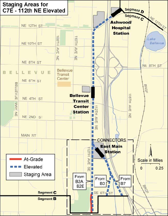
46 EXHIBIT 2-57 Alternative C3T Construction Staging Areas EXHIBIT 2-58 Alternative C4A Construction Staging Areas EXHIBIT 2-59 Alternative C7E Construction Staging Areas EXHIBIT 2-60 Alternative C8E Construction Staging Areas 2-46 East Link Project Final EIS


47 EXHIBIT 2-61 Alternative C9A Construction Staging Areas Below-Grade Light Rail Construction Tunnel and underground station construction may include cut-and-cover, tunnel-boring, and/or sequential excavation mining methods. Exhibits 2-54 to 2-57 illustrate which technique is planned for each of the tunnel alternatives. In general, cut-and-cover techniques would be used for all stations, where tunnels are too short to justify boring, where tunnel depths are shallow, and where tunneling may encounter soil nails or tie-backs from adjacent underground parking garages and deep building foundations. Tunneling areas could require some form of soil stabilization ahead of tunneling operations. Potential methods include jet grouting, ground freezing, rock displacement, or a combination of these. These methods are often performed from the surface. Operations entail grout storage, grout mixing, cleanup facilities, noise suppression enclosures, and other environmental considerations. Mining is done through two techniques: using a tunnel boring machine or sequential excavation. Mined construction begins with construction of an access portal. On hillsides, the access portal can be dug directly into the hillside (using the cut-and-cover EXHIBIT 2-62 Alternative C14E Construction Staging Areas method). In flatter areas, an access shaft must first be excavated. Once a portal or shaft is dug, the mining equipment, such as a tunnel boring machine, can begin excavating earth. The resulting excavated materials (spoils) are transported to the shaft or portal for stockpiling and/or hauling. The type of tunnel boring machine used depends on geological conditions. Some tunnel boring machines are supported by a small supply train that brings in materials and takes out the excavated spoils. Conveyors or pipes can also be used to bring out the spoils, depending on the machine type. Sequential excavation mining consists of the excavation of a tunnel by many smaller but defined steps. This technique can use conventional excavation equipment or a rapid excavation machine rather than a tunnel boring machine. Sequential excavation is slower and more expensive than using a boring machine. The need for fresh air requires that a mechanical ventilation system and fans be in place during mined construction. Fans may run for 24 hours a day and could be audible at tunnel portals, stations, or access locations. East Link Project Final EIS 2-47
48 Cut-and-cover stations (like cut-and-cover tunnel segments) would be excavated from the surface and are essentially large retained cuts. Utilities must be temporarily or permanently diverted or supported across the excavation. The excavation may be decked over at the street level to allow traffic to continue once the excavation is deep enough (10 to 15 feet) to allow earthmoving equipment below. Openings in the decking or bridge are needed to allow removal of the excavated material. Cut-and-cover work also requires backfill following tunnel construction. This work requires the use of material that is imported from other sites or suitable material from the excavation. For underground construction, it is often necessary to install dewatering facilities. Dewatering can be accomplished by a number of mechanical methods, including sumps, pumps, and dewatering wells. These systems require that water be pumped to the surface and discharged or stored or recharged into the ground. Discharge would follow the National Pollutant Discharge Elimination System (NPDES) regulations enforced by the Washington State Department of Ecology (Ecology). 2.5 Environmental Commitments Sound Transit is committed to restoring and enhancing the environment. From the agency s inception, Sound Transit has made every effort to avoid impacts on the environment on all of its projects. Sound Transit is committed to satisfying all applicable federal, state, and local environmental regulations and to mitigate significant adverse environmental project impacts responsibly and reasonably, consistent with Sound Transit policies and applicable regulations. In addition to meeting environmental commitments, Sound Transit would continue to avoid and minimize impacts where possible. Adjustments have been made during conceptual design to avoid or minimize impacts. Following the identification of alternatives for study in this EIS, continual community outreach, workshops, and detailed studies were conducted to receive input from community members and stakeholders and hear their concerns about the alternatives, so that designs might be made sensitive to community facilities. In addition, as environmental impact information was developed, it informed the decision-making on the alternative designs. Minimization and avoidance measures have been considered for all elements of the environment in the EIS. Sometimes it is impossible to completely avoid environmental impacts. Where adverse impacts could not be avoided at this stage of design, the environmental analysis includes potential mitigation measures to reduce the overall impacts (see Chapter 3, Transportation Environment and Consequences, and Chapter 4, Affected Environment and Environmental Consequences). This Final EIS identifies many potential measures to mitigate the adverse impacts of the project alternatives. Sound Transit has committed to some measures as part of the project; other potential measures are noted that might reduce or eliminate impacts. Mitigation measures will be refined through final design and permitting. The Record of Decision (ROD) for East Link will be issued after the Final EIS and will include a list of committed mitigation measures for the project to be built. Appendix I contains a preliminary description of mitigation commitments for the Preferred Alternative. Once an alternative is selected to be built, mitigation commitments will be finalized and documented in the NEPA Record of Decision. In 2004, Sound Transit launched an environmental sustainability program to integrate sustainable business practices throughout the agency. The program called for annually setting and meeting measurable targets for fuel consumption, vehicle emissions, ecosystem protection, green procurement, recycling and waste prevention, energy and water conservation, sustainable design and building, and education and awareness programs, among others. The East Link Project selected to be built will be refined during final design. Throughout final design, Sound Transit will continue to incorporate sustainable design measures into the East Link Project. 2.6 Estimated Project Costs and Funding The current level of project design includes uncertainties regarding the project scope, engineering data, mitigation requirements, schedule, and project delivery methods. Therefore, the project cost estimates at this stage are conceptual costs. These estimates focus on the project elements that are defined consistently across alternatives, that capture the essential physical features of alternatives, and that help distinguish alternatives from one another. The project cost estimates include the following cost elements: 2-48 East Link Project Final EIS
49 Construction costs for facilities, including the trackway/guideway, stations, maintenance facilities and associated improvements, and anticipated mitigation requirements Contingencies that address the varying levels of uncertainty and construction risk that have been identified for alternatives Right-of-way acquisition costs, including tunnel and temporary construction easements Costs for design, permitting, agency administration, and program management In addition, costs for construction change orders, unallocated contingency, and project reserve were estimated as a percentage of the above estimates. Project reserve is an additional contingency intended to cover unforeseen cost impacts. The assignment and allocation of project reserve requires approval by a two-thirds (super) majority of the Sound Transit Board. Sound Transit has updated revenue forecasts to reflect the effects of the recession. The 2010 revenue forecasts lower available funds over the life of the ST2 period by an estimated 25 percent. Consequently, Sound Transit is now managing projects to the base cost estimates without project reserve. The comparative costs presented in this Final EIS reflect a range, with the low end being the base cost estimates and the high end including a project reserve. The range reflects the risk that final project costs could still exceed the base project estimate. The East Link Project would be a composite of one alternative from each segment. Exhibit 2-63 shows a comparison of project cost for the composite of alternatives from Segment A through Segment E. It illustrates the lowest possible cost combination, the highest possible cost combination, and then the two variations in the Preferred Alternatives with and without a tunnel in Segment C, Downtown Bellevue. The high cost includes a tunnel alternative in Segment C, and the low cost includes an elevated alternative in Downtown Bellevue. If the project were only built to the Hospital or Ashwood/Hospital (east end of Segment C), the preferred alternative tunnel would be approximately $1.9 billion or $2.3 billion with reserve, and the preferred alternative at-grade would be $1.7 to just under $2 billion with reserve. In comparison, the high-cost shortened project would be approximately $2.4 to $2.8 billion with reserve, whereas the low-cost shortened project would be approximately $1.5 to $1.8 billion with reserve. Ending at the Overlake Transit Center the easternmost station of Segment D the high-cost project would increase to $3.1 to $3.6 billion with reserve, whereas the preferred tunnel project would be $2.6 billion or $3.1 billion with reserve. The preferred at-grade project would be approximately $2.3 to $2.7 billion with reserve compared to the low-cost project of about $1.9 to $2.4 billion with reserve to the Overlake Transit Center. While the biggest difference is whether or not Segment C includes a tunnel, other factors influence the cost range, such as whether both the 120th and the 130th stations are built and whether portions of the route are primarily at-grade or elevated. The cost estimates by segment are presented in Section after the funding discussion in Section Funding EXHIBIT 2-63 Overall Project Cost Range EXHIBIT 2-63 Overall Project Cost Range Sound Transit's regional transit programs are typically funded through a combination of voter-approved tax initiatives, FTA grants, issuing bonds, and fare box revenue. Sound Transit projects are in large part funded through taxes collected in a three-county district. In November 2008, voters approved a proposition known as the Mass Transit Expansion East Link Project Final EIS 2-49
50 proposal, authorizing Sound Transit to impose an additional five-tenths of one percent sales and use tax and use existing taxes to fund the local share of ST2. The East Link Light Rail Transit Project is included in ST2, which was adopted by the Sound Transit Board on July 24, The ST2 funds construction and operation of the portion of the East Link Project from Seattle to the Overlake Transit Center (Segments A through D). ST2 provides funding for an at-grade or elevated alternative through Downtown Bellevue (Segment C). If the Sound Transit Board selects a tunnel alternative in this segment, additional funding sources would be required. ST2 includes environmental review but not construction for Segment E from the Overlake Transit Center to downtown Redmond. The Sound Transit District has five designated subareas: Snohomish County, North King County, South King County, East King County, and Pierce County. According to current Sound Transit policy, revenues from taxes collected in each of the five subareas must generally be spent for projects and services that benefit the local subarea providing the funding. The project would use revenues from the North King County and East King County subareas. The Rainier would be funded from revenues from North King County, and funding for the majority of the project would come from the East King County Subarea Project Cost Estimates The following subsections describe the range of cost estimates by segment to help compare alternatives that serve similar ridership markets Segment A Preferred Alternative A1 is located exclusively within WSDOT and City of Seattle rights-of-way. The range for Preferred Alternative A1 falls between $635 million without project reserve to up to $750 million (Exhibit 2-64) with project reserve and joint bus-rail operations between Downtown Seattle and Rainier Avenue. The I 90 Two-Way Transit and HOV Operations Project is not part of East Link and is funded separately. The cost for the project to use the I-90 center roadway is addressed in a term sheet between WSDOT and Sound Transit. Sound Transit will receive credit toward a center roadway lease for its funding contributions to the I-90 Two-Way Transit and HOV Operations Project. While the lease amount is not yet finalized, the term sheet anticipates that Sound Transit s funding of the HOV project will fully offset the cost of the I-90 Center Roadway lease. EXHIBIT 2-64 Segment A Cost Estimate The preferred alternative that includes joint light rail and bus operation on the D2 Roadway would cost $16 million to $18 million more than the exclusive operation design option. The only other design option consideration for Preferred Alternative A1 is a possible pedestrian bridge to the Mercer Island instead of access off 77th Avenue SE. The pedestrian bridge option would require approximately $6 million more than the preferred station option with access from 77th Avenue SE Segment B The cost of the Segment B alternatives ranges from approximately $355 million to $590 million with reserve (Exhibit 2-65). The Bellevue Way Alternative (B1) is the lowest cost, primarily because it is completely at-grade. However, to accommodate WSDOT s requirement to maintain both HOV ramps at the I-90/Bellevue way interchange, Alternative B1 would need design revisions that would add approximately $63 million. The next lowest cost alternative is 112th SE At-Grade (B2A) followed by Preferred 112th SE Modified Alternative (B2M). The Preferred Alternative cost range is between $470 million without reserve to $550 million with project reserve. Preferred Alternative B2M would result in lower costs in Segment C connecting to Preferred Alternatives C11A or C9T than the 112th SE Bypass (B3) or BNSF (B7) Alternatives because the route continues north along 112th Avenue SE at-grade while B3 and B7 are elevated and longer as they continue into downtown East Link Project Final EIS
.")
51 The difference in cost of Preferred Alternative B2M as compared with the less expensive Alternative B2A is primarily due to lidded retained cut in front of the Winters House. Alternative B7 is the most expensive of any Segment B alternative and ranges from $515 to $590 million with and without a project reserve (Exhibit 2-65). Alternative B7 is longer than the other alternatives, includes a new bridge over the Mercer Slough, and constructs a new park-and-ride rather than expanding the existing South Bellevue Park-and-Ride. The former BNSF Railway corridor also accommodates possible future freight rail or a pedestrian and bicycle trail to be built and funded by others. B3-114th Extension Design Option adds approximately $70 to 80 million to Alternative B3, making it comparable to BNSF Alternative (B7). The primary reasons for this high cost are both these alternatives are longer than the others and they are primarily elevated. Finally, to accommodate WSDOT s requirement to maintain the east-to-northbound HOV ramp from I-90 to Bellevue Way, the non-preferred Segment B alternatives that use Bellevue Way (Alternatives B2A, B2E, and B3) would cost an additional $23 million to reconfigure the ramp. This is not reflected in the costs as discussed above Segment C Segment C alternatives range from $435 million without project reserve to $1,615 million with project reserve. Segment C alternative cost estimates have the greatest cost range among the alternatives due to the inclusion of at-grade, elevated, and tunnel profiles (Exhibit 2-66). The most costly profile is a tunnel. The at-grade and elevated alternatives have similar costs in this segment due to the amount of utility relocation for at-grade profile in Segment C. The lowest cost alternative is 112th NE Elevated Alternative (C7E) because it is the shortest route and is primarily elevated. The cost range also includes the impacts of Segment B connections. Preferred 108th NE At-Grade (C11A) or Preferred 110th NE Tunnel (C9T) Alternatives would be the lowest cost connection to Preferred Alternative B2M. For C11A, the B3 and B7 connectors are approximately $50 million more than the B2M connector, whereas the EXHIBIT 2-65 Segment B Cost Estimate difference is approximately $100 million for C9T. The Bellevue Way Tunnel Alternative (C1T) has only one connection from Segment B Alternative B1 and therefore has no range in project costs (other than project reserve) and remains the highest-cost Segment C alternative. The 110th NE Elevated (C8E) and 114th NE Elevated (C14E) Alternatives connect only to Alternatives B3 and B7. Preferred Alternative C9T from B2M, which is estimated to range between $790 million without project reserve and $910 million with project reserve, is still substantially less than the cost of the other tunnel alternatives that range from $970 to $1,615 million. Preferred Alternative C11A is $555 million without project reserve and $635 million with project reserve. While the 112th NE Elevated (C7E) and the 114th NE Elevated (C14E) Alternatives are elevated, they are shorter and have lower property acquisition and utility relocation costs and therefore still result in a lower overall cost estimate than Preferred Alternative C11A. The 110th NE At-Grade Alternative (C9A) is comparable to C11A, but shorter in length and avoids rebuilding the Bellevue Transit Center and therefore costs less by approximately $100 million with and $90 million without project reserve. In addition, there are two options for the Ashwood/Hospital, either over I-405 for Alternative C8E or east of I-405 for Alternative C3T, C4A, or C7E. The less expensive of the two options is the station east of I-405 because of either less property acquisition or lower construction difficulty. The station located over I-405 includes an East Link Project Final EIS 2-51


52 additional 25 percent cost ($12 million) for construction over I-405. As shown in Table 2-6, the total cost of combining Segment B with Segment C alternatives provides another cost comparison. The combined cost in Table 2-6 of Segment B alternatives with Segment C alternatives reflects only the low and high cost with project reserve relative to that unique combination, whereas the low and the high costs presented in the preceding bar graphs reflect the cost range for each alternative with any of the possible combinations. Some of the cost savings in Segment B are lost when connecting to Segment C. For instance, Alternative B1 is the least expensive in Segment B, but when combined with C1T, they collectively become the most expensive combination. For Preferred Alternative C9T, the cost difference connecting to B2M is $45 to $140 million less than connecting to B3 or B7, respectively, whereas for Preferred Alternative C11A, connecting from B2M and B3 are similar but connecting from B7 would be $90 million more. Generally, the Segment C alternatives cost less when connecting from the alternatives that travel up 112th Avenue SE because they are shorter and on average, the connection from B7 is $100 million more than connections from 112 th Avenue NE connectors. The exception is the B2A connector for both the 106th NE Tunnel (C2T) and 108th NE Tunnel (C3T) alternatives. The B2A connection through the King County District Court House site is the most costly (between $85 and $140 million more than the least costly connector because it extends these tunnels further south). EXHIBIT 2-66 Segment C Cost Estimate EXHIBIT 2-67 Segment D Cost Estimate Although some of the Segment B to C alternative combinations presented in Table 2-6 are not directly studied in the EIS, they are possible, and therefore, costs are provided to complete the comparison Segment D The Segment D alternatives range from approximately $470 million without project reserve to $875 million with reserve (Exhibit 2-67) East Link Project Final EIS
53 TABLE 2-6 Total Costs of Combining Segment B and C Alternatives a ($ millions 2007 dollars) Alternative Preferred 112th SE Modified Alternative (B2M) Bellevue Way Alternative (B1) 112th SE At- Grade Alternative (B2A) 112th SE Elevated Alternative (B2E) 112th SE Bypass Alternative (B3) BNSF Alternative (B7) Preferred 108th NE At-Grade Alternative (C11A) $1,020 to $1,170 NA b $940 to $995 to $1,020 to 1,080 c $1,145 c $1,260 $1,110 to $1,280 Preferred 110th NE Tunnel Alternative (C9T) $1,270 to $1,460 N/A b $1,180 to 1,235 to $1,315 to 1,355 c 1,420 c $1,595 $1,405 to $1,615 b $1,760 to Bellevue Way Tunnel Alternative (C1T) N/A $2,020 N/A b N/A b N/A b N/A b 106th Tunnel Alternative (C2T) N/A b b $1,575 to N/A $1,810 $1,565 to $1,795 $1,540 to $1,770 $1,640 to $1, th Tunnel Alternative (C3T) N/A b b $1,480 to N/A $1,705 $1,415 to $1,630 $1,450 to $1,670 $1,560 to $1,795 Couplet Alternative (C4A) N/A b b $935 to N/A $1,075 $975 to $1,120 $1,035 to $1,195 $1,125 to $1, th NE Elevated Alternative (C7E) N/A b N/A b $850 to $975 $880 to $1,010 $945 to $1,085 $1,035 to $1, th NE Elevated Alternative (C8E) N/A b N/A b N/A b b $1,040 to N/A $1, th NE At-Grade Alternative (C9A) N/A b N/A b c $905 to $985 to $850 to $980 $1,045 b $1,135 $1,125 to $1,295 $1,070 to 1, th Avenue NE Elevated Alternative (C14E) N/A b N/A b N/A b b $925 to N/A $1,145 $1,015 to $1,165 a Range reflects both project cost reserves and options unique to each combination of alternatives. b These Segment B-C alternative combinations are not possible. c Although these Segment B-C alternative combinations are not directly studied in the EIS, they are possible, and therefore, costs are provided. The design options for Preferred NE 16th At-Grade Alternative (D2A) fall within the same range $670 million without reserve to $765 million with project reserve. Preferred Alternative D2A is less expensive overall than the Alternative D2A - NE 24th Design Option because remaining along SR 520 and positioning the Overlake Village adjacent to SR 520 as opposed to traveling along the north side of NE 24th Street and the west side of 152nd Avenue NE results in a savings of up to $50 million (or close to a 10 percent savings). The savings is a result of fewer real estate acquisitions and shorter linear miles of light rail track compared to traveling on NE 24th Street and 152nd Avenue NE. There is relatively little difference in cost among Segment D alternatives, with one exception. The SR 520 Alternative (D5) is the lowest because it avoids the construction of two stations, the 120th and 130th stations. Preferred Alternative D2A is somewhat lower in cost than the remaining alternatives because an at-grade profile can be less expensive than elevated and retained-cut profiles. For the connection options to Segment C, property acquisition is the primary factor in the cost difference between the NE 12th Street connector (from C3T, C4A, C7E, or C8E) versus the former BNSF Railway connector (from C11A, C9T, C1T, C2T, C9A, or C14E). The former BNSF Railway connector would cost up to 7 percent more than the NE 12th Street connector for all Segment D alternatives except for Alternative D5, for which the BNSF connector would be as much as 5 percent less than the NE 12th Street connector. Alternative D5 also has two design options on the east end of Segment D, which account for less than a $3 million difference in the estimate. For the alternatives following NE 15/16th Street Corridor, either the 120th or 130th may be built, or both. For Preferred Alternative D2A or Alternative D3, a single station rather than both stations would reduce the overall project costs by almost $11 million. For the NE 16th Elevated Alternative (D2E), the cost reduction would be approximately $47 million because an elevated station is more costly. East Link Project Final EIS 2-53

54 Segment E Exhibit 2-68 shows the costs range in Segment E and highlights the Preferred Marymoor Alternative (E2) cost estimate. Segment E alternatives range from $505 million without project reserve to $795 million with project reserve. The Segment E alternatives have many portions of their routes in common. The differences lie in how they serve Downtown Redmond. Preferred Alternative E2 costs among the lowest of the Segment E alternatives at a projected $555 million without reserve to $635 million with project reserve. Adding the Redmond Transit Center Design Option onto Alternative E2 would increase this cost by approximately $150 million. E2 - Redmond Transit Center Design Option is the most expensive alternative because it has the longest route with an additional station and is the only alternative with right-of-way costs along 161st Avenue NE. However, when considering Preferred Alternative E2 (without E2 - Redmond Transit Center Design Option), then Preferred Alternative E2 and Alternative E4 are both somewhat equal in being the lowest cost alternatives. One important design consideration is where all alternatives cross the SR 520/SR 202 interchange and Bear Creek. The Redmond Way Alternative (E1) is elevated over both Bear Creek and the SR 520/SR 202 interchange. This option is approximately $11 million more than passing under the SR 520/SR 202 interchange in a retained cut and then crossing over Bear Creek, as the other two alternatives do. The range in Segment E costs is shown in Exhibit Maintenance Facilities The range in maintenance facility costs is shown in Exhibit The 116th Maintenance Facility (MF1) would be the most expensive alternative due to the amount of excavation required to create a level site, ranging from approximately $430 million without project reserve to $465 million with reserve. The variation of cost for the maintenance facility is influenced by the alternative connections. Simply stated, the longer the access track from the alternative to the maintenance facility, the higher the associated costs. The BNSF Maintenance Facility (MF2), at approximately $310 million to $315 million with project reserve, and the SE Redmond Maintenance Facility (MF5), between $240 million without project reserve and $280 million with reserve, would be the lowest cost alternatives due to lower site development EXHIBIT 2-68 Segment E Cost Estimate EXHIBIT 2-69 Maintenance Facilities Cost Estimate costs, with MF5 the least expensive due to slightly lower right-of-way costs. The SR 520 Maintenance Facility (MF3) would have higher site development costs than either MF2 or MF5, but lower costs than MF1. MF1 and MF3 would be the least expensive for Alternative D5 connection, whereas MF2 would be slightly less expensive for all other 2-54 East Link Project Final EIS

55 Segment D alternatives. MF5 would have the lowest cost with connection from Alternative E Operating and Maintenance Costs Operating and maintenance costs for the East Link Project were estimated based on the estimates developed for the ST2 adopted in July East Link operating costs are the annual system operating costs for the completed light rail system in the ST2 as allocated to the East Link extension from Seattle. The light rail system operating costs are based on a labor build-up model of a type used for FTA New Starts cost estimates; it was calibrated to the relatively wellestablished operating and maintenance costs for the Link Initial Segment under the existing agreements with King County. The major determinants of operating costs are service levels, running time, and trackway profile. The more frequent the service and the longer the line, the more vehicles it takes to maintain equivalent headways. Shorter alternatives with fewer stations have lower operating costs. In terms of line and station maintenance, at-grade is the lowest cost, elevated the next highest, and tunnels the highest. The ST2 estimated annual operating cost for the East Link alternatives from Seattle to the Overlake Transit Center is $25 million (2007$) for 2030 (ST2, Appendix C). An additional $6 million annual operating cost is estimated for Segment E, for a total estimated annual operating cost for the entire East Link Project of about $31 million. These estimates will be refined as the project definition evolves and detailed operating plans are developed. 2.7 Next Steps and Schedule Project Decision After the Final EIS has been issued, the Sound Transit Board will make a final decision on the project alternative to be built, amending or confirming the Preferred Alternative identified in the this Final EIS. In addition, a second light rail storage and light maintenance facility was funded as part of ST2 to support systemwide expansion, including East Link. The location of this facility will be determined through operations analysis and future site planning which will consider locations throughout the Sound Transit service area. This future analysis would also include additional environmental review of the potential maintenance facility whether located at one of the sites evaluated in the East Link EIS or in another part of the service area Federal Approval Chapter 2 Alternatives Considered FTA will issue a decision document referred to as the federal Record of Design (ROD). The ROD states FTA s decision on the project, identifies the alternatives considered by FTA in reaching its decision, and itemizes Sound Transit s commitments to mitigate project impacts. Issuance of the ROD completes the NEPA process and is a prerequisite for federal funding or approvals Project Schedule Table 2-7 shows the anticipated schedule milestones for the East Link Project. The length of time for the project would depend on available funds and construction costs. The East Link Project is included in the ST2. The ST2 funds construction and operation of the portion of the East Link Project from Seattle to the Overlake Transit Center. Sound Transit anticipates beginning construction on the East Link Project in 2015, and construction from Seattle to Overlake would be completed in approximately 6 years, followed by approximately 1 year of startup and testing activities. Sound Transit anticipates that service would be provided to Overlake by 2022 or Benefits and Disadvantages of Delaying Project Implementation As required by SEPA (Washington Administrative Code (5)(c)), this section discusses the TABLE 2-7 Project Milestones East Link Project Final EIS 2-55
2.1 Introduction. Chapter 2 Alternatives Considered
 Chapter 2 Alternatives Considered 2.1 Introduction This chapter describes the alternatives and how they were developed for study in this Environmental Impact Statement (EIS). The alternatives described
EAST LINK PROJECT. Environmental Scoping Information Report. Seattle to Bellevue to Redmond. September 2006
 SCOPING EAST LINK PROJECT Environmental Scoping Information Report Seattle to Bellevue to Redmond September 2006 CENTRAL PUGET SOUND REGIONAL TRANSIT AUTHORITY TABLE OF CONTENTS Introduction... 2 What
Route located on two parallel roadways in which one direction runs on one road and one direction on the other road. Both routes are at street level.
 Resource Glossary EAST LINK Light Rail Illustrative Glossary Terms At-grade couplet Route located on two parallel roadways in which one direction runs on one road and one direction on the other road. Both
3.1 Introduction Transportation Elements and Study Area Meeting the Need for the Project
 Chapter 3 Transportation Environment and Consequences 3. Introduction This chapter summarizes the characteristics of the transportation system in the East Link Project vicinity and discusses potential
6.1 Performance in Meeting Project Goals and Objectives
 Chapter 6 Alternatives Evaluation This chapter evaluates how East Link would meet the project Purpose and Need, and analyzes the benefits, environmental impacts, and cost-effectiveness of the project as
Federal Way Link Extension
 Federal Way Link Extension Draft EIS Summary Route & station alternatives and impacts Link Light Rail System Map Lynnwood Mountlake Terrace Lynnwood Link Extension Shoreline 14th Northgate 40 Northgate
Letter EL652 City of Mercer Island. Page 1. No comments n/a
 Letter EL652 City of Mercer Island Page 1 No comments n/a Page 2 Response to comment EL652 1 Section 4.5.3 of the Final EIS presents the range of potential impacts of the project. This project also lists
FINAL. Sound Transit Long-Range Plan Update. Issue Paper S.1: Tacoma Link Integration with Central Link. Prepared for: Sound Transit
 Sound Transit Long-Range Plan Update Issue Paper S.1: Tacoma Link Integration with Central Link Prepared for: Sound Transit Prepared by: Quade & Douglas, Inc. FINAL March 2005 Foreword This issue paper
Sound Transit East Link: Bus/LRT System Integration Study
 Sound Transit East Link: Bus/LRT System Integration Study Prepared For: Sound Transit King County Metro Mercer Island WSDOT Prepared By: CH2M HILL July, 2014 1 SOUND TRANSIT EAST LINK: BUS/LRT SYSTEMES
4.0 TIER 2 ALTERNATIVES
 4.0 TIER 2 ALTERNATIVES The Tier 2 Alternatives represent the highest performing Tier 1 Alternatives. The purpose of the Tier 2 Screening was to identify the LPA utilizing a more robust list of evaluation
Restoration of Historic Streetcar Services in Downtown Los Angeles
 Restoration of Historic Streetcar Services in Downtown Los Angeles Alternatives Analysis Community Update Meeting August 2, 2011 Introduction Key players Local lead agency: Metro Federal lead agency: Federal
Executive Summary. Draft Environmental Impact Statement/Environmental Impact Report ES-1
 Executive Summary Introduction The Eastside Transit Corridor Phase 2 Project is a vital public transit infrastructure investment that would provide a transit connection to the existing Metro Gold Line
Attachment E3 Vibration Technical Memorandum
 Attachment E3 Technical Memorandum 77 South Bedford Street Burlington, MA 01803 T 781.229.0707 F 781.229.7939 E jross@hmmh.com W www.hmmh.com TECHNICAL MEMORANDUM To: Alisa Swank, CH2M HILL Jodi Ketelsen,
2016 PSRC REGIONAL & KING COUNTYWIDE EASTSIDE FUNDING AWARDS. Eastside Transportation Partnership September 9, 2016
 2016 PSRC REGIONAL & KING COUNTYWIDE EASTSIDE FUNDING AWARDS Eastside Transportation Partnership September 9, 2016 1 2 PSRC 2016 Project Selection Process 2018-2020 Estimated FHWA Funds Available: (Summary)
RTID Travel Demand Modeling: Assumptions and Method of Analysis
 RTID Travel Demand Modeling: Assumptions and Method of Analysis Overall Model and Scenario Assumptions The Puget Sound Regional Council s (PSRC) regional travel demand model was used to forecast travel
STH 60 Northern Reliever Route Feasibility Study Report
 #233087 v3 STH 60 Northern Reliever Route Feasibility Study Report Washington County Public Works Committee Meeting September 28, 2016 1 STH 60 Northern Reliever Route Feasibility Study Hartford Area Development
Note: The October 2007 version of this report has been updated in this December 2008 report to present costs in year 2007 dollars.
 Sound Transit Phase 2 South Corridor LRT Design Report: SR 99 and I-5 Alignment Scenarios (S 200 th Street to Tacoma Dome Station) Tacoma Link Extension to West Tacoma Prepared for: Sound Transit Prepared
Link LRT: Maintenance Bases, Vehicles and Operations for ST2 Expansion
 Project Number SYS-LRT Subareas All Primary Mode Impacted Link Facility Type Link Service Version Number 4.0 Date Last Modified 7/24/2008 Project Locator Map Short Project Description Construct new light
Committee Report. Transportation Committee. Business Item No
 Committee Report Business Item No. 2015-280 Transportation Committee For the Metropolitan Council meeting of December 9, 2015 Subject: METRO Blue Line Extension (Bottineau Light Rail Transit) Revised Scope
Exhibit A Sound Transit Board Resolution R Selecting the bicycle, pedestrian, and parking access improvements to be built for the Puyallup
 Exhibit A Sound Transit Board Resolution R2016-07 Selecting the bicycle, pedestrian, and parking access improvements to be built for the Puyallup Access Improvement Project. RESOLUTION NO. R2016-07 Selecting
METRO Orange Line BRT American Boulevard Station Options
 METRO Orange Line BRT American Boulevard Station Options Bloomington City Council Work Session November 18, 2013 Christina Morrison BRT/Small Starts Project Office Coordinating Planning and Design AMERICAN
ANDERSON PROPERTY SITE ANALYSIS
 ANDERSON PROPERTY SITE ANALYSIS Introduction The Montgomery County Department of Transportation (MCDOT) initiated a feasibility study in the fall of 2012 to evaluate the need for transit service expansion
East Link Extension. September 16, Bel-Red Conclusion to Final Design Open House Public Involvement Summary
 East Link Extension September 16, 2014 Bel-Red Conclusion to Final Design Open House Public Involvement Summary Table of contents 1 Background 2 Overview 2 Notification 3 Open House Overview 4 Comment
EUGENE-SPRINGFIELD, OREGON EAST WEST PILOT BRT LANE TRANSIT DISTRICT
 EUGENE-SPRINGFIELD, OREGON EAST WEST PILOT BRT LANE TRANSIT DISTRICT (BRIEF) Table of Contents EUGENE-SPRINGFIELD, OREGON (USA)... 1 COUNTY CONTEXT AND SYSTEM DESCRIPTION... 1 SYSTEM OVERVIEW... 1 PLANNING
Waco Rapid Transit Corridor (RTC) Feasibility Study
 Feasibility Study") Waco Rapid Transit Corridor (RTC) Feasibility Study Chris Evilia, Director of Waco Metropolitan Planning Organization Allen Hunter, General Manager Waco Transit System Jimi Mitchell, Project Manager AECOM
Waco Rapid Transit Corridor (RTC) Feasibility Study Chris Evilia, Director of Waco Metropolitan Planning Organization Allen Hunter, General Manager Waco Transit System Jimi Mitchell, Project Manager AECOM
City of Bellevue East Link Light Rail B7/C9T to NE 2nd Portal (B7 Revised) Alternative RP03 Interim Analysis Report
 Alternative RP03 Interim Analysis Report") East Link Light Rail B7/C9T to NE nd Portal (B7 Revised) Alternative RP3 Interim Analysis Report 538/RP3 Review Draft 3 May Arup North America Ltd 43 Columbia Street Suite Seattle WA 984 United States
East Link Light Rail B7/C9T to NE nd Portal (B7 Revised) Alternative RP3 Interim Analysis Report 538/RP3 Review Draft 3 May Arup North America Ltd 43 Columbia Street Suite Seattle WA 984 United States
Level 2 Alternatives Screening Report
 FEDERAL WAY TRANSIT EXTENSION Level 2 Alternatives Screening Report CENTRAL PUGET SOUND REGIONAL TRANSIT AUTHORITY Table of Contents 1.0 Executive Summary 1.1 Purpose of This Report. 1 1 1.2 Purpose and
Chapter 9 Recommended Locally Preferred Alternative and Alternatives for Evaluation in Draft SEIS/SEIR
 Chapter 9 Recommended Locally Preferred Alternative and Alternatives for Evaluation in Draft SEIS/SEIR 9.0 RECOMMENDED LOCALLY PREFERRED ALTERNATIVE AND ALTERNATIVES FOR EVALUATION IN DRAFT SEIS/SEIR
7 COMPARATIVE EVALUATION OF ALTERNATIVES
 7 COMPARATIVE EVALUATION OF ALTERNATIVES 7.1 INTRODUCTION This chapter presents the comparative analysis of the four Level 2 build alternatives along with a discussion of the relative performance of the
I-820 (East) Project Description. Fort Worth District. Reconstruct Southern I-820/SH 121 Interchange
 Project Description. Fort Worth District. Reconstruct Southern I-820/SH 121 Interchange") I-820 (East) Project Description Fort Worth District Reconstruct Southern I-820/SH 121 Interchange I-820 from approximately 2,000 feet north of Pipeline Road/Glenview Drive to approximately 3,200 feet
I-820 (East) Project Description Fort Worth District Reconstruct Southern I-820/SH 121 Interchange I-820 from approximately 2,000 feet north of Pipeline Road/Glenview Drive to approximately 3,200 feet
Restoration of Historic Streetcar Services in Downtown Los Angeles
 Restoration of Historic Streetcar Services in Downtown Los Angeles Early Scoping Meeting for Alternatives Analysis (AA) May 17, 2011 Introduction Key players Local lead agency: Metro Federal lead agency:
Business Advisory Committee. July 7, 2015
 Business Advisory Committee July 7, 2015 1 Today s Topics Outreach Update TI #1 and 2: Target Field Station Connection to I-94: Recommendation 85 th Station Configuration 93 rd Station Configuration DEIS
Executive Summary. Treasure Valley High Capacity Transit Study Priority Corridor Phase 1 Alternatives Analysis October 13, 2009.
 Treasure Valley High Capacity Transit Study Priority Corridor Phase 1 Alternatives Analysis October 13, 2009 Background As the Treasure Valley continues to grow, high-quality transportation connections
Public Information Workshop
 Public Information Workshop Charlotte County-Punta Gorda MPO - Meeting Rooms A and B March 29, 2018 Welcome to the Public Information Workshop for Harborview Road Project Development and Environment (PD&E)
King County Metro. Columbia Street Transit Priority Improvements Alternative Analysis. Downtown Southend Transit Study. May 2014.
 King County Metro Columbia Street Transit Priority Improvements Alternative Analysis Downtown Southend Transit Study May 2014 Parametrix Table of Contents Introduction... 1 Methodology... 1 Study Area...
1.0 Purpose and Need for Federal Way Link Extension
 1.0 Purpose and Need for Federal Way Link Extension The Central Puget Sound Regional Transit Authority (Sound Transit) is proposing the Federal Way Link Extension (FWLE) to expand the regional light rail
West Broadway Reconstruction/LRT Design. March 19, 2015
 West Broadway Reconstruction/LRT Design March 19, 2015 1 Meeting Agenda 6:05 6:30 PM Brief presentation What we heard Project overview 6:30 8:00 PM Visit Six Topic Areas Road and LRT design elements Pedestrian
MOTION NO. M Preferred Alternative for the Puyallup Station Access Improvement Project
 MOTION NO. M2014 64 Preferred Alternative for the Puyallup Station Access Improvement Project MEETING: DATE: TYPE OF ACTION: STAFF CONTACT: Capital Committee Board PROPOSED ACTION 8/14/14 8/28/14 Recommendation
East Link light rail: Bel-Red/Overlake Open House Summary
 East Link light rail: Bel-Red/Overlake Open House Summary April 2010 East Link Light Rail Project Overview East Link is Sound Transit s voter-approved project to build light rail between Seattle and the
Link Light Rail Operations and Maintenance Satellite Facility
 September 2015 Link Light Rail Operations and Maintenance Satellite Facility TRANSPORTATION TECHNICAL REPORT Appendix E1 Central Puget Sound Regional Transit Authority Appendix E.1 TABLE OF CONTENTS PROJECT
CEDAR AVENUE TRANSITWAY Implementation Plan Update
 CEDAR AVENUE TRANSITWAY Implementation Plan Update EECUTIVE SUMMARY DECEMBER 2015 Executive Summary In 2013, the Twin Cities metropolitan area s first bus rapid transit (BRT) line, the METRO Red Line,
Chapter 4 : THEME 2. Transportation
 Chapter 4 : THEME 2 Strengthen connections to keep the Central Area easy to reach and get around 55 Figure 4.2.1 Promote region-wide transit investments. Metra commuter rail provides service to the east,
Metro Transit Update. Christina Morrison, Senior Planner Metro Transit BRT/Small Starts Project Office. John Dillery, Senior Transit Planner
 Metro Transit Update Christina Morrison, Senior Planner Metro Transit BRT/Small Starts Project Office John Dillery, Senior Transit Planner Metro Transit Service Development May 16, 2013 1 Transit Planning
Develop ground transportation improvements to make the Airport a multi-modal regional
 Project Overview TRANSPORTATION IMPROVEMENTS WHAT ARE THE PROJECT GOALS? Transportation transportation hub. Develop ground transportation improvements to make the Airport a multi-modal regional Land Use
BROWARD BOULEVARD CORRIDOR TRANSIT STUDY
 BROWARD BOULEVARD CORRIDOR TRANSIT STUDY FM # 42802411201 EXECUTIVE SUMMARY July 2012 GOBROWARD Broward Boulevard Corridor Transit Study FM # 42802411201 Executive Summary Prepared For: Ms. Khalilah Ffrench,
appendix 4: Parking Management Study, Phase II
 appendix 4: Parking Management Study, Phase II A4-1 A4-2 Eastlake Parking Management Study Final Phase 2 Report Future Parking Demand & Supply January 6, 2017 Submitted by Denver Corp Center III 7900 E.
Crenshaw-Prairie Transit Corridor Study Public Meetings
 Crenshaw-Prairie Transit Corridor Study Public Meetings Darby Park: Wednesday, February 20, 2008 6:30 8:00 PM US Bank Community Room: Thursday, February 21, 2008 6:30 8:00 PM Nate Holden Performing Arts
5. OPPORTUNITIES AND NEXT STEPS
 5. OPPORTUNITIES AND NEXT STEPS When the METRO Green Line LRT begins operating in mid-2014, a strong emphasis will be placed on providing frequent connecting bus service with Green Line trains. Bus hours
Community Advisory Committee. October 5, 2015
 Community Advisory Committee October 5, 2015 1 Today s Topics Hennepin County Community Works Update Project Ridership Estimates Technical Issue #4:Golden Valley Rd and Plymouth Ave Stations Technical
Energy Technical Memorandum
 Southeast Extension Project Lincoln Station to RidgeGate Parkway Prepared for: Federal Transit Administration Prepared by: Denver Regional Transportation District May 2014 Table of Contents Page No. Chapter
Tempe Streetcar. March 2, 2016
 Tempe Streetcar March 2, 2016 Tempe Profile 40 sq. miles, highest density in state University Town, center of region Imposed growth boundaries (density increase) Mixed use growth/intensifying land use
3.0 Transportation Environment and Consequences
 3.0 Transportation Environment and Consequences 3.1 Summary This chapter describes the characteristics of the transportation system in the FWLE vicinity and discusses potential impacts and mitigation measures
3.15 SAFETY AND SECURITY
 3.15 SAFETY AND SECURITY Introduction This section describes the environmental setting and potential effects of the alternatives analyzed in this EIR with regard to safety and security in the SantaClara-Alum
Rocky Mount. Transportation Plan. Transportation Planning Division. Virginia Department of Transportation
 2020 Transportation Plan Developed by the Transportation Planning Division of the Virginia Department of Transportation in cooperation with the U.S. Department of Transportation, Federal Highway Administration
HIGH CAPACITY TRANSIT CORRIDOR STUDY UTILITIES TRANSPORTATION ECOSYSTEMS DEMOGRAPHICS TECHNICAL MEMORANDUM 12/20/2013 7/17/2014 DRAFT
 HIGH CAPACITY TRANSIT CORRIDOR STUDY FEDERAL WAY TO TACOMA REPORT LEVEL 2 OPTIONS EVALUATION 12/20/2013 7/17/2014 DRAFT CULTURAL, VISUAL UTILITIES TRANSPORTATION PROPERTY PARKS NOISE LAND HAZARDOUS ECOSYSTEMS
TORONTO TRANSIT COMMISSION REPORT NO.
 Form Revised: February 2005 TORONTO TRANSIT COMMISSION REPORT NO. MEETING DATE: October 24, 2012 SUBJECT: DOWNTOWN RAPID TRANSIT EXPANSION STUDY (DRTES) PHASE 1 STRATEGIC PLAN ACTION ITEM RECOMMENDATIONS
Kendall Drive Premium Transit PD&E Study Project Kick-Off Meeting SR 94/Kendall Drive/SW 88 Street Project Development and Environment (PD&E) Study
 Study") Florida Department of Transportation District Six Kendall Drive Premium Transit PD&E Study Project Kick-Off Meeting SR 94/Kendall Drive/SW 88 Street Project Development and Environment (PD&E) Study What
Florida Department of Transportation District Six Kendall Drive Premium Transit PD&E Study Project Kick-Off Meeting SR 94/Kendall Drive/SW 88 Street Project Development and Environment (PD&E) Study What
Major Widening/New Roadway
 Revised Evaluation s Major Widening/New Roadway This page provides a summary of any revisions made to the draft scores presented at the October th Attributable Funds Committee meeting. The information
29 April Sound Transit 3 Draft Plan. Dear Sound Transit Boardmember:
 29 April 2016 Re: Sound Transit 3 Draft Plan Dear Sound Transit Boardmember: Thank you for the opportunity to comment on the Sound Transit 3 Draft Plan. Sierra Club supports transportation policies that
San Rafael Transit Center. Update. Golden Gate Bridge, Highway & Transportation District Transportation Committee of the Board of Directors
 Transportation Committee November 17, 2016 Agenda Item No. 5, Update on the San Rafael Transit Center Relocation San Rafael Transit Center Relocation Study Update 11/17/16 Golden Gate Bridge, Highway &
CITY OF ANN ARBOR, MICHIGAN 301 E. Huron St., P.O. Box 8647 Ann Arbor, Michigan
 Date: Wednesday, June 24, 2014 Location: Ann Arbor District Library Attendees: 40 citizen attendees Ann Arbor Station Environmental Review Public Meeting Meeting Notes Meeting #2 The second public meeting
5 EVALUATION OF ALTERNATIVES
 5 EVALUATION OF ALTERNATIVES This chapter begins by evaluating how well the Lynnwood Link Extension alternatives meet the project s Purpose and Need Statement. It then compares the environmental and transportation
Leadership NC. November 8, 2018
 v Leadership NC November 8, 2018 Planning for our region s growth The Triangle is one of the fastestgrowing regions in the nation. More than 2 million people are already part of the equation, and the
SOUTHERN GATEWAY. Transportation and Trinity River Project Committee 11 May 2015
 SOUTHERN GATEWAY Transportation and Trinity River Project Committee 11 May 2015 Southern Gateway Project History Began in 2001 as a Major Investment Study [ MIS ], Schematic, and Environmental Assessment
Metro Green Line to LAX Alternatives Analysis. March 2012
 Metro Green Line to LAX Alternatives Analysis 1 2 The Crenshaw/LAX Project Foundation for Metro Green Line to LAX 8.5 mile extension Metro Exposition Line (Crenshaw Exposition) to Metro Green Line (Aviation/LAX
engineering phase and during the procurement of design build contracts.
 CONSIDERATION OF ALTERNATIVES Below-grade trench alignment along Aviation Boulevard, adjacent to LAX south runways. miles. MOS-Century would extend from the Metro Exposition Line to the Aviation/ Century
LOS ANGELES COUNTY METROPOLITAN TRANSPORTATION AUTHORITY (LACMTA) AND FEDERAL TRANSIT ADMINISTRATION (FTA)
 AND FEDERAL TRANSIT ADMINISTRATION (FTA)") LOS ANGELES COUNTY METROPOLITAN TRANSPORTATION AUTHORITY (LACMTA) AND FEDERAL TRANSIT ADMINISTRATION (FTA) NOTICE OF PREPARATION (NOP)/NOTICE OF INTENT (NOI) OF AN ENVIRONMENTAL IMPACT STATEMENT (EIS)/ENVIRONMENTAL
LOS ANGELES COUNTY METROPOLITAN TRANSPORTATION AUTHORITY (LACMTA) AND FEDERAL TRANSIT ADMINISTRATION (FTA) NOTICE OF PREPARATION (NOP)/NOTICE OF INTENT (NOI) OF AN ENVIRONMENTAL IMPACT STATEMENT (EIS)/ENVIRONMENTAL
Summary. S.1 Lynnwood Link Extension
 Summary S.1 The Central uget Sound Regional Transit Authority (Sound Transit) is proposing to build and operate the, which would expand the regional light rail system from Seattle to Lynnwood, Washington.
Challenges in a Post-Katrina Environment East-West Corridor Project Overview February, 2007
 EAST-WEST CORRIDOR Challenges in a Post-Katrina Environment East-West Corridor Project Overview February, 2007 Presentation Agenda Project Overview / Purpose and Need Highway Component Transit Component
DRAFT Subject to modifications
 TREASURE COAST REGIONAL PLANNING COUNCIL M E M O R A N D U M DRAFT To: Council Members AGENDA ITEM 7A From: Date: Subject: Staff September 17, 2010 Council Meeting High Speed Rail Update Introduction The
Attachment D Environmental Justice and Outreach
 Attachment D Environmental Justice and Outreach ATTACHMENT D Environmental Justice and Outreach Indicate whether the project will have disproportionately high and adverse impacts on minority or low income
FREQUENTLY ASKED QUESTIONS
 FREQUENTLY ASKED QUESTIONS 2018 What is the More MARTA Atlanta program? The More MARTA Atlanta program is a collaborative partnership between MARTA and the City of Atlanta to develop and implement a program
Public Meeting. City of Chicago Department of Transportation & Department of Housing and Economic Development
 Public Meeting City of Chicago Department of Transportation & Department of Housing and Economic Development Funded by Regional Transportation Authority September 12, 2011 In partnership with Presentation
VIRGINIA RAILWAY EXPRESS MANASSAS PARK STATION PARKING EXPANSION. Site Evaluation & Recommendation. October 18, 2016
 MANASSAS PARK STATION PARKING EXPANSION Site Evaluation & Recommendation October 18, 2016 1 INFORMATION ITEM Project Overview Parking Demand Site Evaluation VRE Recommended Preferred Alternative Next Steps
Green Line LRT: Beltline Segment Update April 19, 2017
 Green Line LRT: Beltline Segment Update April 19, 2017 Quick Facts On April 11, 2017, City Council approved Administration s recommendation for the Green Line to be underground in the Beltline from 2 Street
Preliminary Definition of Alternatives. 3.0 Preliminary Definition of Alternatives
 3.0 What preliminary alternatives are being evaluated? The alternatives for the East San Fernando Valley Transit Corridor project that were considered for screening include the No Build Alternative, Transportation
IMPROVEMENT CONCEPTS
 IMPROVEMENT CONCEPTS for the South Novato Transit Hub Study Prepared by: January 11, 2010 DKS Associates With Wilbur Smith Associates IMPROVEMENT CONCEPTS Chapter 1: Introduction 1. INTRODUCTION The strategic
Business Advisory Committee. November 3, 2015
 Business Advisory Committee November 3, 2015 1 Today s Topics DEIS Cost Estimate 2 Assumptions Revised Cost Estimate Revised Project Scope Cost Estimate Overview Position Statement Discussion Municipal
I-20 EAST TRANSIT INITIATIVE Tier 1 and Tier 2 Alternatives Screening Report EXECUTIVE SUMMARY
 EXECUTIVE SUMMARY The purpose of this report is to document the results of the Tier 1 and Tier 2 Screening of alternatives for the I-20 East Transit Initiative. The two-tier screening process presented
June WASHINGTON STATE DEPARTMENT OF TRANSPORTATION Alaskan Way Viaduct and Seawall Replacement Program Seattle, Washington
 DESIGN DEVIATION NOs. 1 & 2 Horizontal Stopping Sight Distance and Shoulder Width Reduction SR 99 S. Holgate St to S. King St. Viaduct Replacement Stage 2 MP 29.89 TO MP 30.78 XL-3237 PIN-809936D June
The Eastern Connector Study November, 2007 planning for the future
 The Eastern Connector Study November, 2007 planning for the future In late 2006, Albemarle County and the City of Charlottesville jointly initiated the Eastern Connector Corridor Study. The Project Team
Subarea Study. Manning Avenue (CSAH 15) Corridor Management and Safety Improvement Project. Final Version 1. Washington County.
 Corridor Management and Safety Improvement Project. Final Version 1. Washington County.") Subarea Study Manning Avenue (CSAH 15) Corridor Management and Safety Improvement Project Final Version 1 Washington County June 12, 214 SRF No. 138141 Table of Contents Introduction... 1 Forecast Methodology
Subarea Study Manning Avenue (CSAH 15) Corridor Management and Safety Improvement Project Final Version 1 Washington County June 12, 214 SRF No. 138141 Table of Contents Introduction... 1 Forecast Methodology
EXECUTIVE SUMMARY. Introduction
 EXECUTIVE SUMMARY Introduction The purpose of this study is to ensure that the Village, in cooperation and coordination with the Downtown Management Corporation (DMC), is using best practices as they plan
A Better Transit Plan
 A Better Transit Plan for East King County Proposed by the Eastside Transportation Association September 15, 008 A Better Transit Plan Eastside cities and elected officials do not appear cognizant of the
Clifton Corridor Transit Initiative. Briefing to Great Lakes Community February 11, 2016
 Clifton Corridor Transit Initiative Briefing to Great Lakes Community February 11, 2016 Neighborhood Concerns and Requests Provide a general overview and background of the project What are the different
PROPOSAL OF HIGH CAPACITY URBANAUT PUGET SOUND REGIONAL MONORAIL MASTERPLAN WASHINGTON STATE, USA
 PROPOSAL OF HIGH CAPACITY URBANAUT PUGET SOUND REGIONAL MONORAIL MASTERPLAN WASHINGTON STATE, USA Not to be copied in part without reference to author Urbanaut Company Inc. Monorail Tel: 425 434-6570 Fax:
DART Priorities Overview
 City of Dallas Transportation and Trinity River Project Committee DART Priorities Overview Gary C. Thomas President/Executive Director August 10, 2015 City of Dallas Transportation & Trinity River Committee
Welcome. Green Line in Your Community
 Welcome Green Line in Your Community Today's session will provide you with information about Administration's recommendation for connecting the Green Line in the Beltline to Victoria Park and Inglewood/Ramsay
Table of Contents INTRODUCTION... 3 PROJECT STUDY AREA Figure 1 Vicinity Map Study Area... 4 EXISTING CONDITIONS... 5 TRAFFIC OPERATIONS...
 Crosshaven Drive Corridor Study City of Vestavia Hills, Alabama Table of Contents INTRODUCTION... 3 PROJECT STUDY AREA... 3 Figure 1 Vicinity Map Study Area... 4 EXISTING CONDITIONS... 5 TRAFFIC OPERATIONS...
Chapter 7: Travel Demand Analysis. Chapter 8. Plan Scenarios. LaSalle Community Center. Image Credit: Town of LaSalle
 Chapter 7: Travel Demand Analysis Chapter 8 Plan Scenarios LaSalle Community Center. Image Credit: Town of LaSalle 164 Chapter 8: Plan Scenarios Moving Ahead for Progress in the 21 st Century Act (MAP
West Seattle and Ballard Link Extensions
 West Seattle and Ballard Link Extensions Stakeholder Advisory Group Meeting April 17, 2018 Agenda Welcome & Introductions Previous Meeting Summary What We Heard March Alternatives Development Process Level
West LRT. Alignment Update and Costing Report May Calgary Transit Transportation Planning Clifton ND Lea Consultants
 West LRT Alignment Update and Costing Report 2006 May Calgary Transit Transportation Planning Clifton ND Lea Consultants West LRT Update Background The service area for West LRT is generally described
The Jack A. Markell Trail Delaware s Bicycle Highway New England Bike- Walk Summit
 The Jack A. Markell Trail Delaware s Bicycle Highway 2018 New England Bike- Walk Summit The Jack A. Markell Trail Sometimes a very difficult project, including significant investment and perseverance,
CROSSING RAIL PROJECT (P4) RAIL
 RAIL") GRAND CROSSING RAIL PROJECT (P4) Community Advisory Group October 10, 2012 1:30 pm Grand Crossing Park Field House 7655 S. Ingleside Avenue, Chicago GRAND CROSSING RAIL PROJECT (P4) Community Advisory
GRAND CROSSING RAIL PROJECT (P4) Community Advisory Group October 10, 2012 1:30 pm Grand Crossing Park Field House 7655 S. Ingleside Avenue, Chicago GRAND CROSSING RAIL PROJECT (P4) Community Advisory
VIRGINIA RAILWAY EXPRESS MANASSAS PARK STATION PARKING EXPANSION. Public Meeting June 20, 2017
 MANASSAS PARK STATION PARKING EXPANSION Public Meeting June 20, 2017 1 AGENDA Project Status Schematic Design Circulation Traffic Analysis Proposed Garage Location Next Steps Cost Estimate 2 PROJECT PHASES
I-405 and SR 522/NE 145th Bus Rapid Transit. Elected Leadership Groups Meeting November 30, 2018
 I-405 and SR 522/NE 145th Bus Rapid Transit Elected Leadership Groups Meeting November 30, 2018 Agenda Welcome and Introductions Public Comment BRT Connection in Bothell Common Elements: Bus base, Station
Green Line Long-Term Investments
 Enhancements Short-term improvements to keep Austin moving. Investments Long-term projects to support our future. Mobility Hubs MetroRapid MetroRail MetroExpress Connectors Circulators Project Connect
Green Line LRT: Beltline Recommendation Frequently Asked Questions
 Green Line LRT: Beltline Recommendation Frequently Asked Questions June 2017 Quick Facts Administration has evaluated several alignment options that would connect the Green Line in the Beltline to Victoria
Transportation Committee Revised Project Scope and Cost Estimate. November 23, 2015
 Transportation Committee Revised Project Scope and Cost Estimate November 23, 2015 1 Today s Topics Revised Project Scope Revised Cost Estimate Municipal Approval Action 2 3 Revised Project Scope Project
RECOMMENDATION PAPER TO THE DULLES CORRIDOR COMMITTEE
 DULLES RAIL RECOMMENDATION PAPER TO THE DULLES CORRIDOR COMMITTEE ANALYSIS OF ALTERNATIVE AIRPORT ALIGNMENTS FOR METRORAIL AT WASHINGTON DULLES INTERNATIONAL AIRPORT MARCH 2011 PURPOSE This paper presents