Technical Report 2 Drexel University Rec Center Philadelphia, PA
|
|
|
- Brittney Dixon
- 5 years ago
- Views:
Transcription

1 2010 Technical Report 2 Drexel University Rec Center Philadelphia, PA Britnei Godusky Lighting/Electrical Faculty Advisor: Professor Dannerth 10/27/2010
2 Executive Summary The following report provides a comprehensive analysis of the existing electrical and power distribution system of the Drexel University Recreation Center. Compiled using the drawings and specifications provided by the architect and electrical engineer, it presents a description of the voltage, power sources, emergency distribution, and all switchgear and electrical equipment including mechanical and communications systems. A single line diagram and schedules of all transformers, luminaires, provide an in-depth overview of the design. The 84,400ft three story recreation center s overall electric system is fed through an interior service entrance from Drexel s main campus system and is delivered at 13.2kVA. Once transformed to 480Y/277V, this is distributed via main distribution panels throughout the building, converted to 208Y/120V for receptacle and appliance loads. Three service entrance sizing methods are performed, using overall building type, NEC load determination, and actual loading derived from panelboard and mechanical schedules. Even with an added 25% for future expansion, the actual size of the service entrance was much larger than what was calculated due to safety and system design considerations. 2
3 Table of Contents General Building Statistics... 4 Summary Description of Distribution System... 5 Utility Company Information... 5 Service Entrance... 6 Voltage Systems... 6 Emergency Power Systems... 6 Locations of Switchgear... 7 Over-current Devices... 9 Transformers... 9 Grounding Special Equipment Lighting Loads Lighting Control Mechanical and other Loads Service Entrance Size Environmental Stewardship Design Design Issues Communication Systems Appendix A: Single Line Drawings Appendix B: HID Lamp and Ballast Cut Sheets
4 Drexel University Recreation Center general building information location NW Corner of 33 rd and Market Streets Philadelphia, PA building occupant Drexel University faculty and students occupancy type Gymnasium/Lounge Café size The entire athletic center is 250,000sf but the addition covered by this investigation is 84,000sf total levels Three levels above grade dates of construction June 2008-December 2009 actual cost $41 million project delivery method Design-bid-build with a gross maximum price primary project team Drexel University Sasaki Associates EwingCole Pennoni Associates Turner Construction owner architecture interiors landscaping mechanical/electrical/plumbing structural fire protection civil site design geotechnical/environmental engineering contractor restaurant fit-out LDL Studio Inc. FXBonnes Associates Inc. architect mechanical/electrical/plumbing fire protection 4
5 Summary Description of Distribution System The DRC s electrical system is a radial system with a 13.2 kv service entrance in the main electrical room in the basement of the Fitness Center. Existing PECO service switchgear in the Nesbit Building feeds the service entrance to the DRC. A 1500kVA transformer that steps down the voltage from 13.2kV to a 480Y/277V, 3P, 4W voltage system is located in a newly constructed substation to feed the new addition as well as the existing part of the DAC. A 2500A main distribution system provides power 480Y/277V power to all loads. Dry-type step-down transformers convert power to 208Y/120V, 3P, 4W for receptacles and appliance loads, while lighting panels use the 277V power. An indoor diesel emergency generator rated at 350kW, 480Y/277P, 3P, 4W provides backup power to emergency branches powering emergency/egress lighting, sewage ejector pumps, existing sump pumps, and boiler controls. Utility Company Information The DRC is a powered by PECO as a part of Drexel University s campus system. PECO, a subsidiary of Exelon Corporation, is based in Philadelphia and serves southeastern Pennsylvania Market Street P.O. Box 8699 Philadelphia, PA Drexel receives General Service under PECO s GS rate schedule. The monthly costs per kwh under this schedule are as follows: VARIABLE DISTRIBUTION SERVICE CHARGE: 3.64 per kwh for the first 80 hours use of billing demand 1.71 per kwh for the next 80 hours use of the billing demand 1.08 per kwh for additional use; except 0.47 per kwh over both 400 hours use of billing demand and 2,000 kwh Plus the COMPETITIVE TRANSITION CHARGE: 8.86 per kwh for the first 80 hours' use of billing demand 4.18 per kwh for the next 80 hours' use of billing demand 2.64 per kwh for additional use; except 1.17 per kwh over both 400 hours' use of billing demand and 2,000 kwh 5
6 Service Entrance The Drexel Recreation Center is tied into Drexel s campus system and fed directly from the Nesbit Building through an existing manhole in the exterior plaza to the north of the building. All components of the service entrance are owned and provided by Drexel, the owner. Metering, as well as all equipment is indoors in centrally located electrical room 132 located on the basement level below the gymnasium. The primary transformer, located on a 4 concrete pad inside the electrical room, is rated at 1500kVA, and converts 13.2kV to the 480Y/277V, 3P, 4W serving the Rec Center s main power system. The main distribution switchboard distributes power through typical normal power feeders out to existing transformers and panels on each additional floor. Voltage systems Power enters the Drexel Rec Center on a 480Y/277V, 3P, 4W voltage system. Lighting panels are all fed by 480/277V 3P, 4W feeders EXCEPT in the restaurant, which uses its own distribution panel for lighting and steps down to a 208/120V bus for lighting panels operating at 120V.Receptacles and appliance loads operate at 120V and are fed off of a 208Y/120V, 3P, 4W feeder. Most mechanical equipment runs on 460V for 3P operation or 208/120V for 1P operation. Emergency Power Systems A 350kW/437.5kVA liquid cooled emergency natural gas generator is located in the central emergency generator room 133 next to the electric room in the basement, on the north side of the building. The generator has starting batteries with battery charger that operates on 120V AC. A diesel belly tank is provided at the base of the generator for a minimum of 17 hours back-up. Main emergency automatic transfer switches feed two emergency main power distribution panels also located in room 133. The 250A main distribution panel is powered by a 200A 4P automatic transfer switch and serves all HVAC equipment and emergency power to the restaurant. The 100A emergency distribution panel is powered by a 100A 4P automatic transfer switch and provides backup power for the elevators, security monitoring system, and automatic exterior door locks. In addition to supplying all emergency power to the Rec Center addition, the generator also replaces the existing Daskalakis Athletic Center Generator. Emergency power is provided to the existing facility through a 150A 4P automatic transfer switch connected to an existing 250A 6
7 emergency distribution panel located in the existing DAC main electric room. Normal power for this panel is provided by the existing DAC sub-station. Locations of Switchgear The main utility transformer and unit sub-station are located at the service entrance in electrical switchgear room 132, on the main level beneath the gymnasium. A main emergency switchboard located in the emergency generator room provides power to the emergency distribution panels. There are six main distribution panels, two emergency, two standard distribution, and two power panels, all located in the first floor mechanical area either in the electrical switchgear room, adjacent emergency generator room, or nearby boiler room, with one switchboard feeding the restaurant from the restaurant s electrical room. Two transformers located in the electrical room on each of the upper floors convert the power down to 208/120V power. The restaurant converts all of its power for lighting, receptacle, and mechanical loads locally in its own electrical room and janitor storage closet. Below are the major equipment and panelboard schedules for the Drexel University Recreation Center. Major Equipment Schedule Tag Type Floor Room Room Name 7 DWG Number Detail ATS-ES-1 Transfer Switch First 133 Emer. Gen. Rm E1-01A E5-01 ATS-ES-2 Transfer Switch - - Ex. DAC Main Elec. Rm. - E5-01 ATS-OS-1 Transfer Switch First 133 Emer. Gen. Rm E1-01A E5-01 DP-1 Dist. Panel First 132 Elec. Swgr Rm. E1-01A E5-01 DP-3 Dist. Panel First Restaurant E1-01B - DP-L Dist. Panel First 151 Rest. Elec. Room E3.1R - Emerg. Dist. EDP-ES-1 First 133 Emer. Gen. Rm E1-01A E5-01 Panel EDP-OS- Emerg. Dist. First 133 Emer. Gen. Rm. E1-01A E Panel EG-1 Em. Generator First 133 Emer. Gen. Rm. E1-01A E5-01 EMP1-L Dist. Panel First 151 Rest. Elec. Room E3.1R - EMSWBD Em. Main Switchboard First 133 Emer. Gen. Rm E1-01A E5-01 PP-1 Power Panel First 136 Boiler Room E1-01A E5-01
8 PP-3 Power Panel Third 302 Elec. Room E1-03A E5-01 SS-1 Substation First 132 Elec. Swgr Room E1-01A E5-01 T-1 Transformer First 132 Elec. Swgr Room E1-01A E5-01 T-2 Transformer First 132 Elec. Swchgr Room E1-01A E5-01 Tag Type Floor Room Room Name DWG Number Detail T-3 Transformer Second 202 Elec. Room E1-02A E5-01 T-4 Transformer Third 302 Elec. Room E1-03A E5-01 T-5 Transformer First 133 Emer. Gen. Room E1-01A E5-01 T-6 Transformer Third 302 Elec. Room E1-03A E5-01 T-7 Transformer First 133 Emer. Gen. Room E1-01A E5-01 T-8 Transformer Second 202 Elec. Room E1-02A E5-01 T-9 Transformer First 151 Rest. Elec. Room E3.1R - T-10 Transformer First 151 Rest. Elec. Room E3.1R - T-11 Transformer First 151 Rest. Elec. Room E3.1R - *note: DWGs denoted with suffix R are part of the restaurant fit-out plans. Tag Voltage System Panelboard Schedule Main Size/Typ e Floor Room Room Name Drawing Number AP /120V 3P, 250A First 132 Elec. E1-01A AP /120V 3P, 80A MCB First 137 Future Chiller E1-01A AP /120V 3P, 225A Secon 202 Elec. Room E1-02A AP /120V 3P, 60A MCB Secon 213 Elec. Room E1-02A AP /120V 3P, 80A MCB Secon 213B Elec. Room E1-02A AP /120V 3P, 150A Third 302 Elec. Room E1-03A AP /120V 4W 3P, 80A MCB MCB Third 302 Elec. Room E1-03A EMP1-L 208/120V 4W 3P, 150A First 151 Elec. Room E3.1R EMP2-L 208/120V 4W 3P, 150A MCB First 151 Elec. Room E3.1R ESAP /120V 4W 3P, 0A MCB MLO First 133 Emer. E1-01A ESAP /120V 4W 3P, 60A MLO Third 302 Elec. Generator Room E1-03A ESLP /277V 4W 3P, 60A MLO First 133 Room Emer. E1-01A ESLP /277V 4W 3P, 60A MCS Third 302 Elec. Generator Room E1-03A GDP-L 208/120V 4W 3P, 175A First 151 Elec. Room Room E3.1R KP1-L 208/120V 4W 3P, 225A MLO First Rest. Kitchen E3.0R KP2-L 208/120V 4W 3P, 225A MLO First Rest. Kitchen E3.0R LP /277V 4W 3P, 60A MLO MCB First 132 Elec. E1-01A 4W Switchgear 8 Room
9 LP /277V 3P, 60A MCB Secon 202 Elec. Room E1-02A LP /277V 3P, 60A MCB Third 302 Elec. Room E1-03A MP-H 208/120V 3P, 175A First 151 Elec. Room E3.1R MP-L 240/120V 3P, 125A First Rest. Jan. Closet E3.0R Tag Voltage System Main Size/Type Floor Room Room Name Drawing Number NDP-L 208/120V 3P, 4W 175A MLO First 151 Elec. Room E3.1R OSAP /120V 3P, 4W 100A MLO First 133 Emer. Generator Room E1-01A OSAP /120V 3P, 4W 225A MLO Second 202 Elec. Room E1-02A RP-L 208/120V 3P, 4W 225A MLO First Rest. Staff Corr. E3.0R Over-current Devices Circuit breakers are the main source of over-current protection in the DRC. The service entrance is protected by a 2500 Amp Frame and 2500 Amp Trip circuit breaker. The generator is equipped with a 700A main electronic type circuit breaker feeding the emergency power distribution panel. It is also equipped with a Ground Fault Sensing Coil (GFSC) that detects a ground fault occurrence but will not cause the circuit break to trip. Most of the normal individual panel boards have bolt on circuit breakers sized in accordance with the NEC with AIC ratings of 18,000, with a few feeding through to a second section of main lug only. All emergency panels are main lug only. Elevators are protected by 100 and 60A fuses. All transformers are protected by disconnect switches rated in accordance to the transformer load. At the service entrance, a Transient Voltage Surge Suppressor is installed with a 60A fuse disconnect before the Unit Substation. Transformers The Drexel Rec Center utilizes 10 dry-type step-down transformers providing 208/120 volt utilization voltage to appliance panels, located in electrical rooms on each floor. The main utility transformer is located at the service entrance in electrical switchgear room 132. All transformers operate at optimal efficiency when loaded to 35% of rated capacity. They are required to meet the NEMA TP-1 energy standard in compliance with the EPA Energy Star program. On the following page is an individual transformer schedule for the DRC. 9
10 Tag T -1 Primary Voltage 13200V, 3PH, 3W T-2 480V, 3PH, 3W Secondary Voltage 480Y/277V, 3PH, 4W 208Y/120V, 3PH, 4W Individual Transformer Schedule Size Type Temp. Rise 1500 N/A 150 C 75 T-3 480V, 3PH, 4W 208/120V 3PH, 4W 75 T-4 480V, 3PH, 3W T-5 480V, 3PH, 3W T-6 480V, 3PH, 3W T-7 480V, 3PH, 3W T-8 480V, 3PH, 3W T-9 480V, 3PH, 3W T V, 3PH, 3W T V, 3PH, 3W 208Y/120V 3PH, 4W 208Y/120V 3PH, 4W 208Y/120V 3PH, 4W 208Y/120V 3PH, 4W 208Y/120V 3PH, 4W 208Y/120V 3PH, 4W 208Y/120V 3PH, 4W 240Y/120V 3PH, 4W dry-type, ventilated dry-type, ventilated dry-type, ventilated dry-type, ventilated dry-type, ventilated dry-type, ventilated dry-type, ventilated dry-type, ventilated dry-type, ventilated dry-type, ventilated 150 C 150 C 150 C 150 C 150 C 150 C 150 C 150 C 150 C 150 C Taps (4) 2.5% (4) 2.5% (4) 2.5% (4) 2.5% (4) 2.5% (4) 2.5% (4) 2.5% (4) 2.5% (4) 2.5% (4) 2.5% (4) 2.5% Mounting Pad-Mounted on Floor Pad-Mounted on Floor Pad-Mounted on Floor Pad-Mounted on Floor Pad-Mounted on Floor Pad-Mounted on Floor Pad-Mounted on Floor Pad-Mounted on Floor Pad-Mounted on Floor Pad-Mounted on Floor Pad-Mounted on Floor Grounding The grounding system consists of an underground water pipe, the steel building frame, steel reinforcing bars in the floor slab and made electrodes. The primary ground point is a ground ring connected to the unit substation main ground bus and building metal frame with ¾-inc, 10-foot long copper-clad steel electrodes to ground the outdoor electrical distribution equipment and the emergency generator. A ground grid of ¾-inch 10-foot copper clad electrodes is located at each corner of the building. Three electrodes in each location are located 10 feet apart and connected with bare #3/0 AWG copper conductors. An additional ground bus is located at each telecommunications room and each room with fire alarm, security, and paging equipment. 10
11 Special Equipment Surge protectors are provided in the main and emergency power switchboards and main normal and normal/emergency power distribution panels providing two levels of surge protection for the electrical distribution systems in accordance with the IEEE. Lighting Loads A majority of the lighting throughout the rec center is 4100K linear or compact fluorescent, complimenting the cool colors of the exposed concrete and glass architecture and providing a comfortable, consistent transition throughout the spaces. Halogen incandescent track lighting is used in the restaurant to provide additional flexibility in the space. Induction lighting is used in the rock climbing wall for long lamp-life and low maintenance costs. Below is the luminaire schedule for the Drexel Rec Center. Type Light Source Lamp Type Lamp Watts A1 FLUOR [2] F28T5 28 Luminaire Schedule Ballast Type ELECTRONIC, PS 11 Voltag e Fixtur e Watts Ballast Factor Current Power Factor A1R INCAN MR A2 FLUOR [2] F32T8 32 ELECTRONIC, PS A2R FLUOR 32W CFL 32 ELECTRONIC A3 FLUOR [2] F28T5 28 ELECTRONIC, PS A3R INCAN MR A4 FLUOR [2] F32T8 32 ELECTRONIC, PS A4R INCAN [4] MR A5 FLUOR [2] F28T5 28 A6 FLUOR [2] F14T5 14 ELECTRONIC, PS ELECTRONIC, PS
12 *note: luminaire types with suffix R refer to luminaires located in the restaurant. Type Light Source Lamp Type Lamp Watts Ballast Type Voltage Fixtur e Watts Ballast Factor Current Power Factor A7 FLUOR [2] F21T5 21 A8 FLUOR F28T5 28 C1 FLUOR PLT C1R INCAN MR C2 FLUOR [2] PLT C3 FLUOR PLT C4 FLUOR PLT ELECTRON IC, PS ELECTRON IC, PS ELECTRON IC INTEGRAL XFRMR ELECTRON IC ELECTRON IC ELECTRON IC C4R INCAN PAR C5 FLUOR PLT C6 FLUOR PLT C7 LED - 15 D2 FLUOR F54T5HO 54 D3 FLUOR [2] F32T8 32 E1R LED E5R LED F1R FLUOR [2] F32T8 32 F2R FLUOR F32T8 32 F3R FLUOR F32T8 32 ELECTRON IC ELECTRON IC INTEGRAL DRIVER ELECTRON IC, PS ELECTRON IC, PS INTEGRAL DRIVER INTEGRAL DRIVER ELECTRON IC, PS ELECTRON IC, PS ELECTRON IC, PS W/ FT /F T 1.1/F T G1 INCAN MR-16 WFL G1R INCAN [5] A H2 FLUOR [5] PLT H5 MH 70WMHPAR J2 FLUOR F32T8 32 ELECTRON IC ELECTRON IC ELECTRON IC, PS / (MIN) J4 LED - 18W/F INTEGRAL /FT
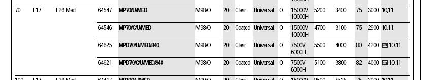
13 T DRIVER *note: luminaire types with suffix R refer to luminaires located in the restaurant. Type Light Source Lamp Type Lamp Watts K1 INDUC QL Ballast Type HF GENERATOR Voltage Fixture Watts Ballast Factor Current Power Factor K3 CMH PAR30MH39 39 ELECTRONIC / M1 INDUC QL M2 INDUC QL HF GENERATOR HF GENERATOR N1 FLUOR [2] PLT ELECTRONIC N2 FLUOR [2] F18DTT 26 N3 FLUOR F14T5 14 N4 FLUOR [2] F14T5 14 PA FLUOR [2] F28T5/SEC 28 ELECTRONIC, PS ELECTRONIC, PS ELECTRONIC, PS ELECTRONIC, PS PB FLUOR [8] PLT ELECTRONIC R1R INCAN [6] A S1R INCAN MR T1 FLUOR [2] F32T8 32 T2 FLUOR [2] F32T8 32 T3 FLUOR [2] F32T8 32 X1 LED X1R LED X2 LED - 3 ELECTRONIC, PS ELECTRONIC, PS ELECTRONIC, PS INTEGRAL DRIVER INTEGRAL DRIVER INTEGRAL DRIVER /FT /FT /FT Z1 CMH CMH ED17 70 ELECTRONIC /0.37 *note: luminaire types with suffix R refer to luminaires located in the restaurant (MIN) 13
14 Lighting Controls The DAC utilizes occupancy sensors in offices, restrooms, and storage areas with 30-minute automatic shut-off in compliance with ASHRAE/IESNA The largely glass façade provides the opportunity for daylight harvesting in the lobby, corridor spaces, fitness center, and gymnasium. In these spaces, photocells control the fluorescent lighting with on/off switching in the corridors and fitness area and three-way switching in the gymnasium. The group fitness rooms and restaurant are controlled by zones, with dimming capabilities in the sports bar and restaurant for a transition between casual daytime dining or sporting events and an intimate evening setting. Mechanical and Other Loads Drexel s Athletic Center is conditioned by seven direct expansion rooftop air-handling units ranging from 1,880cfm for the lobby to 32,550cfm in the fitness/weight rooms. Three parallel BHP hot water heaters are located below the gymnasium partner with the 3,000 gallon fuel oil tank located in an underground vault to power the duel heating system. Four AHUs are variable air volume and three are constant volume, utilizing an associated supply, return, and exhaust duct distribution. Shell space was provided in the mechanical room for a future water cooled chiller. Motor control centers and panelboards provide electrical distribution within the central mechanical system. Mechanical system chilled and condenser water pumps, domestic water pumps, exhaust and supply fans, cooling towers, and other control systems are served by normal power from the main distribution panels. Tag Description Load Units RTU-1 RTU-2 MULTIPURPOSE GYM SUPPLY FAN MULTIPURPOSE GYM RETURN FAN WEIGHTS/FITNESS SUPPLY FAN WEIGHTS/FITNESS RETURN FAN Mechanical Equipment Schedule Motor Amps Volts Phase Assumed Power Factor Load in KVA Load in KW 25 HP HP HP HP
15 Tag Description Load Units Motor Amps 15 Voltage Phase Assumed Power Factor Load in KVA Load in KW RTU-3 WEIGHTS/FITNES S SUPPLY FAN 2@20 HP WEIGHTS/FITNES S RETURN FAN 40 HP RTU-4 FITNESS SUPPLY FAN 15 HP FITNESS RETURN FAN 5 HP RTU-5 FIRST FLOOR SUPPLY FAN 20 HP FIRST FLOOR RETURN FAN 5 HP RTU-6 UPPER LOBBY SUPPLY FAN 1.54 HP RTU-7 RESTAURANT SUPPLY FAN 15 HP RESTAURANT RETURN FAN 5 HP B-1 BOILER 3/4 HP B-2 BOILER 3/4 HP B-3 BOILER 3/4 HP P- HEATING HOT HW01 WATER LOOP 1-1/2 HP P- HEATING HOT HW02 WATER LOOP 1-1/2 HP P- HEATING HOT HW03 WATER LOOP 1-1/2 HP P- HEATING HOT HW04 WATER LOOP 7-1/2 HP P- HEATING HOT HW05 WATER LOOP 7-1/2 HP P- FTR01 RADIATION LOOP 1-1/2 HP P- FINN TUBE FTR02 RADIATION LOOP 1-1/2 HP P- DOMESTIC HOT DHW0 WATER HEATER 1 1/3 HP FCU- ELEC. SWGR 1(AH) ROOM FLA FCU- ELEC. SWGR 1(CU) ROOM FLA CRU- 1(AH) MDF ROOM FLA CRU- MDF ROOM 131-1(CU) CONDENSING 12.8 FLA EF-1 BOILER ROOM 136 EXHAUST 1 HP
16 Tag Description Load Units 16 Motor Amps V Phase Assumed Power Factor Load in KVA Load in KW UH-2 UNIT HEATER 1/50 HP UH-3 UNIT HEATER 1/50 HP UH-4 UNIT HEATER 1/50 HP UH-5 UNIT HEATER 1/50 HP UH-6 UNIT HEATER 1/50 HP UH-7 UNIT HEATER 1/50 HP UH-8 UNIT HEATER 1/50 HP EMERGENCY EF-2 5 HP GENERATOR ROOM EMERGENCY EF-2A 3 HP GENERATOR ROOM LOCKER ROOM EF-3 1 HP EXHAUST EQUIP ISSUE / STOR EF-4 1/6 HP EXHAUST ELECTRICAL ROOM EF-5 1/6 HP EXHAUST ELECTRICAL ROOM EF-6 1/6 HP EXHAUST ALCOVE 206, 306 EF-7 1/6 HP EXHAUST GYM STORAGE EF-8 1/6 HP EXHAUST BOILER SF-1 2 HP COMBUSTION ELECTRIC REHEAT ERH-1 1/100 HP COIL ELECTRIC UNIT EUH-1 1/100 HP HEATER ELECTRIC UNIT EUH-2 1/100 HP HEATER CEUH- ELECTRIC UNIT 7/100 HP HEATER CEUH- ELECTRIC UNIT 7/100 HP HEATER CEUH- ELECTRIC UNIT 7/100 HP HEATER UH-1 UNIT HEATER 1/50 HP UH-9 UNIT HEATER 1/50 HP UH-10 UNIT HEATER 1/50 HP SS- ELEVATOR MACH. 1(AH) ROOM FLA SS- ELEVATOR MACH. 1(CU) ROOM FLA
17 SS- 2(AH) ELEVATOR MACH. ROOM FLA Tag Description Load Units 17 Motor Amps V Phase Assumed Power Factor Load in KVA Load in KW SS- ELEVATOR MACH. 2(AH) ROOM FLA SS- ELEVATOR MACH. 2(CU) ROOM FLA SS-3A IT 203A 0.2 FLA SS-3B IT 203B 0.2 FLA SS- IT 203A, AV 203B 12.5 FLA (CU) SS-4A IT 303A 0.2 FLA SS-4B IT 303B 0.2 FLA SS- IT 303A, AV 303B 12.5 FLA (CU) DUPLEX BOILER FOP-1 2@3/4 HP TRANSFER (FU) P- FUTURE CHILLED 30 HP CW01 WATER PUMP (FU) P- FUTURE CHILLED 30 HP CW02 WATER PUMP (FU) P- FUTURE CHILLED 30 HP CW03 WATER PUMP (FU) P- FUTURE CHILLED 75 HP CW04 WATER PUMP (FU) P- FUTURE CHILLED 75 HP CW05 WATER PUMP GAS BOOSTER GBP-A 1 HP PUMP HWRP- HOT WATER 1/12 HP A RETURN SP-A SUMP PUMP 3/10 HP RWRP- REUSE PUMPS 2@5 HP FP-5-1 VAV /5 HP FP-5-2 VAV /5 HP FP-5-3 VAV - OFFICE AND STORAGE 1/5 HP JP JOCKEY PUMP 0.5 HP RH-1 RADIANT HEATER RH-2 RADIANT HEATER RH-3 RADIANT HEATER RH-4 RADIANT HEATER RH-5 RADIANT HEATER RH-6 RADIANT HEATER
18 RH-7 RADIANT HEATER Tag Description Load Units Motor Amps V Phase Assumed Power Factor Load in KVA Load in KW RH-8 RADIANT HEATER RH-9 RADIANT HEATER RH-10 RADIANT HEATER Total Load (kw) Plumbing Equipment Schedule Tag GBP- A HWR P-A RWR P- A/B SP-A Description CENTRIFUGAL PLUMBING PUMP IN LINE PLUMBING PUMP MULTISTAGE PLUMBING PUMP SUBMERSIBLE PLUMBING PUMP Loa d Units Motor Amps Voltag e Phase Assumed Power Factor Load in KVA Load in KW 1 HP /1 2 HP HP /1 0 HP Total Load (kw) Architectural Equipment Schedule Tag Description Load Units Motor Amps Voltage Phase Assumed Power Factor Load in KVA Load in KW E-1 Holeless Hydraulic Elevator 40 HP E-2 Holed Elevator 20 HP Total Load (kw)
19 Tag Description Load Units Kitchen Equipment Schedule Motor Amps 19 Voltage Phase Assumed Power Factor Load in KVA Load in KW 1 GAS CONVECTION OVEN 0.5 HP BASKET FRYER FRYER HOLDER STATION BASKET FRYER BASKET FRYER RANGE WITH OVEN REFRIGERATED CHEF BASE GAS GRIDDLE COOK & HOLD A EXHAUST HOOD CONTROLS B EXHAUST HOOD MAKEUP AIR UNIT 2 HP C EXHAUST HOOD EXHAUST FAN #1 1 HP D EXHAUST HOOD EXHAUST FAN #2 1.5 HP FIRE SUPRESSION SYSTEM FOOD PREP TABLE 0.5 HP HOT/COLD DROP 0.25 HP COLD DROP IN 0.25 HP FOOD PREP TABLE 0.5 HP REFRIGERATOR 0.5 HP REFRIGERATOR 0.5 HP WARMER A ICE MACHINE B ICE MACHINE CONDENSER UNDERCOUNTER REFRIGERATOR 0.25 HP LETTUCE CRISPER 0.25 HP SLICER 0.33 HP SALAD PREP UNIT 0.2 HP LETTUCE CRISPER 0.25 HP SODA DISPENSER
20 Tag Description Load Units Motor Amps Voltage Phase Assumed Power Factor 46 COFFEE MAKER HORIZONTAL FREEZER 0.25 HP HOT CARVING SHELF A WALK IN COOLER LIGHTING B WALK IN COOLER EVAPORATOR COILS 0.05 HP C WALK IN COOLER CONDENSING UNIT A EXTERIOR WALK IN LIGHTS & B EXTERIOR WALK IN EVAPORATOR COILS C EXTERIOR WALK IN EVAPORATOR COILS D EXTERIOR WALK-IN CONDENSING UNIT BOTTLE COOLER BLENDER STATION UNDERCOUNTER DISHWASHER BACKBAR COOLER 0.33 HP A ICE MAKER B ICE MAKER CONDENSER PASS-THRU BACKBAR COOLER PASS-THRU COCKTAIL STATION Load in KVA Total Load (kw) Load in KW 20
21 Service Entrance Size Below are three service entrance sizing methods, each more specific than the one before. As you can see, the load calculations vary from method to method. The first method approaches the building as a type and area, for use during the Schematic design phases to get a general idea of the load. During design development, the load is divided by type and the loads are calculated based on what type of load is present in a more accurate square footage breakdown of the project based on loads given in the NEC. The actual loading method is used to create the construction documents, and should be the most accurate sizing calculation. Demand factors are taken into effect for a more precise look at the breakdown of the building. All loads were taken directly from panelboard schedules and mechanical schedules for accurate calculations. The actual size Conceptual/Schematic Phases: Load per Square foot Method Building Type VA/sf Building Area VA Recreation Center 13 84, Total kva Total Current at 480V A Design Development - NEC Loading Load Type VA/sf Load Area VA Lighting - Schools 3 77, Lighting - Restaurant 3 7, Receptacles , Full-Service Kitchen HVAC 6 84, Computers 200 1, Plumbing Elevators Total kva 1038 Total Current (amps) at 480V
22 Working Drawings- Actual Loading Load Type Demand Factor Load KVA Demand KVA Lighting Receptacles Mechanical Plumbing Elevators Kitchen Total kva (plus 25%) Total Current at 480V Working Drawings- Actual Loading Phase Load-kVA Voltage System Load-Amps Conceptual/Schematic Design Y/277V Design Development Y/277V Working Drawings Y/277V Actual Conditions - Service Entrance - 480Y/277V 2500 Total Actual Conditions 2500 Summary: Available VA/SF Environmental Stewardship Design The electrical system was designed for a LEED certified construction. The allowable lighting power density followed ASHRAE Standard 90.1 using the building type method. Photocells harvest daylight and perform on/off switching throughout the building. Occupancy sensors are used in the restrooms and small offices in accordance with auto-shutoff requirements. Design Issues The majority of the building perimeter was glass, and heavy electrical and telecomm loads were located at these areas (mostly exercise equipment), making it difficult to route different services or locate wiring devices at these locations. On the upper floors, conduit couldn t run below the floor slab or use poke-thru devices because it would be visible to occupants on the floors below with the exposed concrete structure ceilings. Routing conduits and locating wiring devices in the 22
23 floor slab and through the building core was the only option. The architects created a pinch point in a way with an expansion joint which added extra planning and coordination. The concrete structure with exposed slabs caused an emphasis on coordination for the design team in placing system conduits, back boxes, and floor boxes prior to the concrete pour. The rough-in and branch wiring for the lighting and audio-visual systems in the exposed concrete ceiling above had to be premeditated, coordinated and set (mostly light fixtures, photocells, speakers, LCDs, etc). Same for the floor boxes. The 12 concrete slab in which the conduit was routed was actually a structural slab so criteria was created for conduit routing within the slab in order to maintain structural integrity. The designer had to make their own ground using the steel provided throughout the building due to the concrete structure. A special silencing muffler had to be specified to exhaust the generator onto the roof because generator exhaust and noise was an issue. Another issue was day light harvesting and its integration with emergency lighting in the fitness areas. Entire fixtures were put on the Square D lighting control system when on emergency power so that they weren t on 24/7, and they had to be re-wired during testing to take a signal from the life safety transfer switch to get a signal. Fire Alarm Communication Systems The Athletic Center utilizes a full sprinkler system supplied by the city s water supply and designed in accordance with NFPA 13. The floor control stations are located in stair towers 3 and 4 and served from a combination sprinkler riser including floor control valve assemblies, test valves, and drains. A manual fire alarm system is installed with an interfaced control system tied into a campus supervising system. Activation initiates an emergency voice/alarm communication system with using speaker strobes that are white in color. Smoke detection is provided in electrical/telecom rooms, above doors controlled by the system, in elevator lobbies, elevator machine rooms, and in HVAC ducts. Telecommunications Voice and data are provided to the conference rooms, offices, and retail space via 4 PVC sleeves in cable trays mounted within the structural concrete slabs. Emergency phones are located 23
24 in the elevator lobbies, equipment issue room, gymnasium, retail café, and recreation spaces to provide quick response in case of injury during physical activity. A fire alarm annunciator with live voice capability is located at the security desk at the east lobby entrance. Security systems Electronic security control modules are located in the main security room east of the electrical room on the ground level beneath the gymnasium. Each main entrance is controlled by electronic locks with an emergency override located at the security desk. Electronic locks also guard the gymnasium entrance and each stairway. A pole mounted security camera monitors the exterior on the eastern and alternate north entrance to the new facility, with interior cameras located in the athletics gallery. Swipe card access is required to enter the recreation center, and is located beyond the security desk. AV The audiovisual system in the athletic center incorporates an audio/paging system through pendant speakers throughout the lobby and fitness area, as well as ceiling mounted speakers in the gymnasium. LCD screens are located in the climbing lounge, at the east and west lobby entrances, with a total of twenty screens mounted on each floor of the fitness area. AV equipment rooms are provided on the second and third floors with the second floor space feeding the LCD screens and speakers on the first floor. 24
25 Appendix A E0-03 Single Line Diagram Single-Line Diagram Drawing List E Single Line Diagram New Work Normal E Single Line Diagram New Work Normal E0-05 Single Line Diagram New Work - Emergency 25

26 Copyright 800A, 480/277V BUS 100A, 480/277V BUS 2008 by EwingCole 18 KAIC MIN. 250A, 480/277V BUS Project Engineer Engineering Leader Mary Alcaraz Michael Ginder DREXEL UNIVERSITY RECREATION CENTER BJG OCT. 27, 2010 NTS
27
28
29

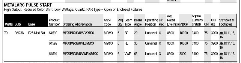
30 Fixture Types H5, Z1 30
31 Fixture Type K3 31

32 Fixture Types M1, M2 32
Technical Report 2: Electrical Systems Existing Conditions + Building Load Summary Report
 Technical Report 2: Electrical Systems Existing Conditions + November 4, 2008 Advisor: Professor Ted Dannerth EXECUTIVE SUMMARY This technical report examines the existing electrical conditions for The
Diane Emert Senior Thesis 2005 Broadway Plaza, Rochester, MN. Electrical Appendix
 Electrical Appendix 121 Panel Switchgear/Panelboard Calculations Future Load (VA) Growth (125%) (VA) FLA (A) Corrected Amps Wire Size Breaker Size (A) 01LNA 38776 48470 134.54 168.17 2/0 175 02LNA 13134
University of California, San Diego Cal (IT) 2 Technical Assignment #2. Brian Smith
 2 Technical Assignment #2. Brian Smith") University of California, San Diego Cal (IT) 2 Technical Assignment #2 Brian Smith Advisor: Dr. Moeck 31 October 2005 Brian Smith Lighting/Electrical Option University of California, San Diego Cal (IT)
University of California, San Diego Cal (IT) 2 Technical Assignment #2 Brian Smith Advisor: Dr. Moeck 31 October 2005 Brian Smith Lighting/Electrical Option University of California, San Diego Cal (IT)
Electrical Depth. Josh Kreutzberger Lighting/Electrical
 Electrical Depth Electrical Introduction The current power distribution system provides the building with power; however, an alternative design solution was analyzed. This analysis was done in order to
Electrical Existing Conditions and Building Load Summary Report
 Electrical Existing Conditions and Building Load Summary Report Executive Summary: This Electrical Existing Conditions and Building Load Summary Report will describe the general and specific characteristics
THE CARMONY BUILDING ELECTRICAL SYMBOLS AND ABBREVIATIONS NOT ALL SYMBOLS, DEVICES OR ABBREVIATIONS MAY BE USED ELECTRICAL SYMBOLS AND ABBREVIATIONS
 LIGHTING ELECTRICAL SYMBOLS AND ABBREVIATIONS ABBREVIATIONS ELECTRICAL GENERAL NOTES EQUIPMENT POWER DEVICES NOT ALL SYMBOLS, DEVICES OR ABBREVIATIONS MAY BE USED LINE TYPE LEGEND CIRCUITS TELECOMMUNICATION
A. This section includes unit capacitors for power factor correction.
 PART 1: GENERAL 1.01 Wiring Devices A. This section of the standard includes design requirements for wiring connections, including receptacles and switches to equipment specified in other sections. 1.02
2010 PM CM ELECTRICAL. The High-Velocity Edge: Achieving Operational Excellence. 21st Annual Conference
 2010 / PM CM 21st Annual Conference The High-Velocity Edge: Achieving Operational Excellence ELECTRICAL / PM CM 2010 Conference Basic Electrical Rick Miller, PE, LEED AP RNM Engineering, Inc. Vanir Corp.
CHAPTER V RESIDENTIAL WIRING
 CHAPTER V RESIDENTIAL WIRING 5.1. THE SERVICE ENTRANCE Buildings and other structures receive the electrical energy through the service entrance. In residential wiring, the electric company supply this
A. This section includes enclosed dry type transformers for lighting and power loads, with primaries and secondaries rated 600 volts and less.
 PART 1: GENERAL PART I: GENERAL 1.01 Wiring Devices A. This section of the standard includes design requirements for wiring connections, including receptacles and switches to equipment specified in other
SECTION FIVE Electrical. 1A. MAIN LOBBY and LIBERTY AVENUE FACADE
 SECTION FIVE Electrical 1A. MAIN LOBBY and LIBERTY AVENUE FACADE [with SECOND LEVEL LOBBY, GIFT SHOP, BOX OFFICE, GRAND STAIRCASE] Existing Design The main lobby is a large space with few distinct boundaries
GENERAL NOTES ELECTRICAL NOTES MATCH LINE SEE SHEET E1.11 KEY PLAN NTS MATCH LINE SEE SHEET E1.12 SPR-2" SPR-2" SPR-2" SPR-2" SPR-2" SPR-2" TYP DH-108
 MATCH NE SEE SHEET E. N DH-6 DH-7 DH-9 DH-9 DH-8 DH-6 DH-8 MATCH NE SEE SHEET E. GENERAL NOTES KE PLAN NTS 407 North st Street, Suite 0 (5) 96-050 Fax (5) 96-06 N MATCH NE SEE SHEET E. DH- DH- DH- DH-7
Thomas R. Proctor High School
 System Overview Thomas R. Proctor High School has been upgraded from an existing radial electrical system to an expanded radial system. The new system incorporates two separate substations, one located
Electrical Depth. Mark W. Miller Sibley memorial Hospital Grand Oaks Washington, DC CURRENT SYSTEM
 CURRENT SYSTEM The current electrical system can best be described as star; one main switchboard that feeds to the main distribution panel, which then feeds the other panels. The normal power is provided
SECTION LOW VOLTAGE DISTRIBUTION EQUIPMENT
 SECTION 16400 LOW VOLTAGE DISTRIBUTION EQUIPMENT A. General 1. The University does not accept Series-Rated equipment for power distribution switchboards, distribution panels and branch circuit panelboards.
Water side Economizer WC chiller
 Appendices Water side Economizer WC chiller Power Loading Lighting Load W/ft^2 Area (ft^2) W kw 3.5 48152 168532 Water Cooled Chiller kw/ton 0.7 UA Supply Fan BHP kw wall 1069 58 43 window 3642 roof 295
and Haley Darst October 27, Building 100%
 Hotel and Conference Center Haley Darst Lighting Electrical Electrical Consultant: Ted Dannerth October 27, 20100 Electrical Systems Existing Conditions and Building Load Summary Report 100% Table of Contents
Corrections most seen on plan review October 18, 2017 David Rankin Seattle Department of Construction and Inspections
 Corrections most seen on plan review October 18, 2017 David Rankin Seattle Department of Construction and Inspections One-Line / Riser Diagrams Drawings are not reviewed prior to submission. Because of
RETAIL BASE BUILDING REQUIREMENTS DATE: 02/04/2016
 RETAIL BASE BUILDING REQUIREMENTS DATE: 02/04/2016 Overview The following requirements outline the guidelines for designers and project delivery teams in the planning, design and infrastructure requirements
T e c h n i c a l R e p o r t T w o
 T e c h n i c a l R e p o r t T w o JENNA STAUFFER FACULTY ADVISOR: PROF. DANNERTH NOVEMBER 4, 2009 Connecticut Science Center Hartford, CT T a b l e O f C o n t e n t s Executive Summary..Page 2 Section
PRODUCT DRAWING WIRING DIAGRAM FIELD CONNECTIONS MILLENNIUM MODEL YT CHILLERS (STYLE J) WITH ELECTRO-MECHANICAL STARTER JOB DATA:
 WITH ELECTRO-MECHANICAL STARTER JOB DATA:") Supersedes: 160.55-PW4 (1199) FORM 160.55-PW4 (600) PRODUCT DRAWING YORK INTERNATIONAL CORPORATION P.O. Box 1592, YORK, PA 17405 CONTRACTOR ORDER NO. YORK CONTRACT NO. YORK ORDER NO. WIRING DIAGRAM FIELD
Supersedes: 160.55-PW4 (1199) FORM 160.55-PW4 (600) PRODUCT DRAWING YORK INTERNATIONAL CORPORATION P.O. Box 1592, YORK, PA 17405 CONTRACTOR ORDER NO. YORK CONTRACT NO. YORK ORDER NO. WIRING DIAGRAM FIELD
Spring Test 10 due 05/11/2013
 Spring Test 10 due 05/11/2013 Multiple Choice Identify the letter of the choice that best completes the statement or answers the question. 1. When installed in an agricultural building that houses livestock
TRI-SERVICE ELECTRICAL WORKING GROUP (TSEWG) 03/05/09 TSEWG TP-11: UFC N BEST PRACTICES
 03/05/09 TSEWG TP-11: UFC N BEST PRACTICES") TSEWG TP-11: UFC 3-500-10N BEST PRACTICES UFC 3-500-10N was developed by NAVFAC and was used as the starting point for the tri-services development of UFC 3-500-10, Design: Electrical Engineering. UFC
TSEWG TP-11: UFC 3-500-10N BEST PRACTICES UFC 3-500-10N was developed by NAVFAC and was used as the starting point for the tri-services development of UFC 3-500-10, Design: Electrical Engineering. UFC
Technical Report 2: Electrical Existing Conditions Report Faculty Advisor: Dr. Houser October 7, 2010
 Technical Report 2: Electrical Existing Conditions Report Faculty Advisor: Dr. Houser October 7, 2010 . Table of Contents.. Executive Summary.. Summary Description of Distribution System. The Neuroscience
A system fault contribution of 750 mva shall be used when determining the required interrupting rating for unit substation equipment.
 General Unit substations shall be 500 kva minimum, 1500 kva maximum unless approved otherwise by the University. For the required configuration of University substations see Standard Electrical Detail
East Allen County Schools Facilities History Calendar Years October 5, 2015
 East Allen County Schools Facilities History Calendar Years 2007 2015 October 5, 2015 Heritage Attendance Area Heritage Jr./Sr. High School (includes K-12) 2007: Repaved Front Student Parking Lot; and
BID SPECIFICATIONS 2018 TERMINAL BUILDING STANDBY GENERATOR PROJECT
 BID SPECIFICATIONS 2018 TERMINAL BUILDING STANDBY GENERATOR PROJECT The County of Hancock, Maine is seeking bids from qualified firms for the purchase and installation of at least a 20KW backup generator
Michigan State University Construction Standards SECONDARY UNIT SUBSTATIONS PAGE
 PAGE 261116-1 SECTION 261116 PART 1 - GENERAL 1.1 RELATED DOCUMENTS A. Drawings and general provisions of the Contract, including General and Supplementary Conditions and Division 01 Specification Sections,
Electrical Depth. Page 81
 Electrical Depth Introduction The existing electrical system for each space redesigned in my lighting depth had to be adjusted accordingly to the new design. The following electrical depth will illustrate
UNDERSTANDING ELECTRICAL EQUIPMENT AND CONDITIONS OF INCREASED RISK
 UNDERSTANDING ELECTRICAL EQUIPMENT AND CONDITIONS OF INCREASED RISK 5 October 2017 John A. Weber Principal Electrical Engineer, Hartford Steam Boiler Inspection and Insurance Company Electrical Power Transmission
 MDP1 SCHEDULE 1 * PANEL A 14194 5450 DISHWASHER * 2 14285 5450 2 2 3 * PANEL B 15445 SPACE * 2 15689 2 4 5 * PANEL C 18860 SPACE * 2 18976 2 6 7 * PANEL D 14000 SPACE * 2 12185 2 8 9 * SPARE SPACE * 10
Pepco & Delmarva Power. Commercial & Industrial Energy Savings Program Grocery and Convenience Stores October 11, 2012
 Pepco & Delmarva Power Commercial & Industrial Energy Savings Program Grocery and Convenience Stores October 11, 2012 Housekeeping The presentation will be emailed to you after the webinar. If you have
Pepco & Delmarva Power. Commercial & Industrial Energy Savings Program Small Business Program October 3, 2012
 Pepco & Delmarva Power Commercial & Industrial Energy Savings Program Small Business Program October 3, 2012 Housekeeping The presentation will be emailed to you after the webinar. If you have technical
GE Energy Industrial Solutions. EV Charging Station. Application Guide. imagination at work
 GE Energy Industrial Solutions EV Charging Station Application Guide imagination at work EV Charging Station Introduction The GE EV Charging Station offers Level II charging capable of reducing charge
SECTION MOTORS AND VARIABLE FREQUENCY DRIVES
 PART 1 GENERAL 1.1 RELATED DOCUMENTS A. Related Sections: 1. Section 15050 - Basic Mechanical Requirements. 2. Section 15051 - Motors. 3. Section 15185 - Hydronic Pumps. 4. Section 15625 - Centrifugal
Q3RD Series. Single Packaged Heat Pump, Single Phase TECHNICAL SPECIFICATIONS FEATURES AND BENEFITS
 TECHNICAL SPECIFICATIONS Q3RD Series Single Packaged Heat Pump, Single Phase Q3RD-13 SEER 2 thru 4 Ton Units Cooling: 24,000 to 48,000 Btuh Heating: 23,200 to 48,000 Btuh The Q3 Series single packaged
Keycodes Inspection Agency PO Box 391 Bethlehem, Pennsylvania
 Phone 610.866.9663 www.keycodes.net Fax 610.866.2664 info@keycodes.net 2016 Fee Schedule Residential Inspection Services FLAT RATE COSTS INCLUDING PLAN REVIEW (NEW CONSTRUCTION ONLY) RESIDENTIAL DEPOSIT
LIGHT FIXTURE SCHEDULE TYPE DESCRIPTION LAMPS / MANUFACTURER TOTAL
 LIGHT FIXTURE SCHEDULE TYPE DESCRIPTION LAMPS / MANUFACTURER TOTAL VOLTS WATT A 2 FT x 4 FT PARABOLIC 12 CELL (ELECTRONIC BALLASTS) (2) F032T8 PHILIPS LIGHTOLIER: 48 120V. # DPS2G12LS232UNVHI AE SAME AS
James N Thorp Elementary School
 Facility Assessment Summary This report summarizes the findings of a facility assessment completed on the date noted in the document footer below. Assessors rate each facility feature and system by visual
Pretest Module 24 Three-phase Service Entrance
 Pretest Module 24 Three-phase Service Entrance 1. What is the most widely used three-phase service entrance system? 2. What are the three most common voltage combinations for three-phase, four-wire systems?
9/7/2010. Objectives. Article 90. Introduction NEC Significant Changes. Review significant revisions in the 2011 NEC
 2011 NEC Significant Changes Courtesy of NJATC Courtesy of NFPA Presented By: Michael J. Johnston Executive Director of Standards and Safety, NECA Objectives Review significant revisions in the 2011 NEC
GP5RD Series. Single Packaged Air Conditioner, Single Phase TECHNICAL SPECIFICATIONS
 TECHNICAL SPECIFICATIONS GP5RD Series Single Packaged Air Conditioner, Single Phase GP5RD-13 SEER, R-410A 2 thru 5 Ton Units Cooling: 24,000 to 60,000 Btuh The GP5 Series single packaged air conditioners
GQ3RD Series. Single Packaged Heat Pump, Single Phase TECHNICAL SPECIFICATIONS
 TECHNICAL SPECIFICATIONS GQ3RD Series Single Packaged Heat Pump, Single Phase GQ3RD-13 SEER 2 thru 4 Ton Units Cooling: 24,000 to 48,000 Btuh Heating: 23,200 to 48,000 Btuh The GQ3 Series single packaged
COMMERCIAL QUICK REFERENCE
 COMMERCIAL QUICK REFERENCE PROVO CITY POWER STANDARDS ELECTRICAL ENGINEERING UPDATED: 2016 SPECIFICATIONS SUBJECT TO CHANGE WITHOUT NOTIFICATION. 18" MIN. OF TAIL. (NEUTRAL CONDUCTOR MUST BE WHITE OR
NEC 2011 Code Changes
 NEC 2011 Code Changes Articles 280.21-300.50 CHANGES FROM 2008 TO 2011 CODE ARE IN RED Chapter 2 - Wiring and Protection ARTICLE 280 Surge Arresters, Over 1kV III. Connecting Surge Arresters 280.21 Connection
SYSCO INDIANAPOLIS INDIANAPOLIS, INDINA
 SYSCO INDIANAPOLIS INDIANAPOLIS, INDINA November, 2017 Infrared Inspection Report Sysco Indianapolis LLC. 4000 West 62nd Street Indianapolis, Indiana, 46268 Company Contact: Trevor Gray Project: 05161117
Chapter 2 Wiring and Protection Article 200 Use and Identification of Grounded Neutral Conductor Chapter 1 General...9
 Article 90 Introduction...1 90.1 Purpose of the NEC...1 90.2 Scope of the NEC...2 90.3 Code Arrangement...4 90.4 Enforcement...5 90.5 Mandatory Requirements and Explanatory Material...6 90.6 Formal Interpretations...6
Customer Requirements Downtown Secondary Network Service
 Application This standard describes the limitations and requirements for receiving service from the Tacoma Power secondary network system within the City of Tacoma downtown core area. In This Standard
P7RE Series TECHNICAL SPECIFICATIONS. FEATURES and BENEFITS. Single Packaged Air Conditioner
 TECHNICAL SPECIFICATIONS P7RE Series Single Packaged Air Conditioner P7RE 14 SEER 2 thru 5 Ton Units Cooling: 23,800 to 56,000 Btuh The P7 Series single packaged air conditioners are high efficiency self
P3RC-12 SEER 2 Ton thru 4 Ton Units Cooling: 23,800 to 48,000 Btuh
 TECHNICAL SPECIFICATIONS P3R(A,C) Series Single Packaged Air Conditioner, Single Phase P3RA-10 SEER 2 thru 5 Ton Units Cooling: 24,000 to 59,000 Btuh P3RC-12 SEER 2 Ton thru 4 Ton Units Cooling: 23,800
SECTION PANELBOARDS
 SECTION 16470 PANELBOARDS PART 1 - GENERAL 1.1 RELATED DOCUMENTS A. The general provisions of the contract including General and Special Conditions and General Requirements shall apply to all work under
1100 Wilson Boulevard Approximately 4,000 USF. Restaurant. mondayre.com
 Restaurant Opportunity mondayre.com THE PERECT LOCATION» Prime streetfront location on the ground floor of a landmark 1 million SF office complex, with 10 million SF of office space in walking distance»
2018 Consultant s Handbook Division 26 Electrical 2413 Switchboards
 1 General 1.1 Switchboards shall be U.L. listed and labeled. 1.2 Each switchboard shall have its own main disconnecting means unless it is located in the same room as its source of origin. In most cases
WIRING DESIGN & PROTECTION REQUIREMENTS CHECKLIST
 WIRING DESIGN & PROTECTION REQUIREMENTS CHECKLIST Use & Identification of Grounded and Grounding Conductors YES NO N/A Grounded conductors are identifiable and distinguishable from all other conductors.
GLX. Series. 1kW to 16kW Central System
 GLX Series 1kW to 16kW Central System GLX Series Sine Wave RATINGS TABLE Size Input Current @120V Output Current @120V Input Current @277 Output Current @277 Output Watts Battery (DC) Voltage 1kW 16 8
Design Build Deliver. Metal Enclosed Switchgear, 5-35kV 1200 A Maximum Loadbreak, 4000 A Maximum Non-Loadbreak
 Metal Enclosed Switchgear, 5-35kV 1200 A Maximum Loadbreak, 4000 A Maximum Non-Loadbreak Powergrid Solution s Metal Enclosed Switchgear has many different customizable options and configurations. Customers
Generator Fire Safety: Generator assemblies should be located outside the building.
 SECTION 33 70 00 - ELECTRICAL DISTRIBUTION PACKAGED GENERATOR ASSEMBLIES Generator Fire Safety: Generator assemblies should be located outside the building. All fuel piping from the outside of the building
SECTION ENCLOSED SWITCHES AND CIRCUIT BREAKERS
 SECTION 26 28 16 ENCLOSED SWITCHES AND PART 1 - GENERAL 1.1 SUMMARY A. Section includes the following individually mounted, enclosed switches and circuit breakers rated 600V AC and less: 1. Fusible switches.
BUILDING PERMIT FEES
 D-2-a 07/01/11 BUILDING PERMIT S COMMERCIAL RATES Rate MINIMUM New Assembly New Business New Education New Factory/Industrial New Institutional New Mercantile New Storage New Miscellaneous Renovation/Change
Medium Voltage Metal-Enclosed Switches
 Medium Voltage Metal-Enclosed Switches Outdoor Medium Voltage Switch.1 Introduction Product Selection Guide....................................2 Medium Voltage Switch MVS Product Description......................................
M-1.0 FILE NAME: CAFE BIZOU CLIENT: CATHERINE MCKENNA PROJECT: PROJECT NO. REV DESCRIPTION DATE PLAN CHECK
 PLAN CHECK 11072016 12152016 12312015 : 20161122 20161107 20161215 20161020 PROJECT ME LEGEND, NOTES AND SCHEDULES M1.0 FILE ME: Elec. Panel Locker Rm. Electrical (N.I.C.) New Women's (E) Mop Only Sink
P5RF Series Single Packaged Air Conditioner Single Phase
 TECHNICAL SPECIFICATIONS P5RF Series Single Packaged Air Conditioner Single Phase 15 SEER, 12 EER, R-410A 2 thru 5 Ton Units Cooling: 24,000 to 57,500 Btuh The P5 Series single packaged air conditioners
University of Houston Master Construction Specifications Insert Project Name
 SECTION 26 13 13 MEDIUM VOLTAGE SWITCHGEAR PART 1 - GENERAL 1.1 RELATED DOCUMENTS: A. The Conditions of the Contract and applicable requirements of Divisions 0 and 1 and Section 26 00 01, Electrical General
A. This Section includes Low Voltage Switchgear Work, as indicated on the drawings, and as specified herein.
 16425 SWITCHBOARD ************************************************************************************************************* SPECIFIER: CSI MasterFormat 2004 number: 26 24 13 An optional keynote to
The 2017 Program will be comprised of the following: Long Term Projects $15,295,100 Short Term Projects 18,000,100 TOTAL $33,295,200
 PITTSBURGH SCHOOL DISTRICT 2017/2023 CAPITAL PROGRAM The following is the proposed 2017 / 2023 Capital Program. These projects have been identified as a result of Board Actions, input from Facilities,
10 Commercial, Industrial, Agricultural Services
 10 Commercial, Industrial, Agricultural Services This section describes the Power Company requirements for commercial, industrial, and agricultural services. This section covers single phase and three
ADVANCED CALCULATIONS
 ADVANCED CALCULATIONS 101. Why is it permissible in some cases to fuse a #14 AWG motor conductor with a 60 amp breaker when normally a #14 AWG should only be fused at 15 amps? a) the motor can't start
CORRIGENDUM/ ADDENDUM 09 ADDITIONAL REQUIREMENT OF ELEVATOR.
 AMENDMENT-02 TO TECHNICAL SPECIFICATION FOR ELEVATOR (SPEC NO. PE-TS-408-502-A001) 1x800 MW WANAKBORI STPP. CORRIGENDUM/ ADDENDUM 09 ADDITIONAL REQUIREMENT OF ELEVATOR. CL. NO. 2.0 Scope of equipment supply
Outdoor Power Transmission & Distribution
 Description: The purpose of the section is to highlight the current applicable UMCP Design Standards and requirements for Outdoor Power Transmission and Distribution, including but not limited to the following:
CLIF NOTES SERIES (Competent Leveraging of Information and Facts) ELECTRICAL
 ELECTRICAL") CLIF NOTES SERIES (Competent Leveraging of Information and Facts) ELECTRICAL What basic information do you need to know about electrical systems in buildings and why? The Capital Partners Electrical CLIF
CLIF NOTES SERIES (Competent Leveraging of Information and Facts) ELECTRICAL What basic information do you need to know about electrical systems in buildings and why? The Capital Partners Electrical CLIF
P5RF Series Rev "A" Single Packaged Air Conditioner Single Phase
 TECHNICAL SPECIFICATIONS P5RF Series Rev "A" Single Packaged Air Conditioner Single Phase 15 SEER, 12 EER, R-410A 2 thru 5 Ton Units Cooling: 24,000 to 57,500 Btuh The P5 Series single packaged air conditioners
P7RD-A Series TECHNICAL SPECIFICATIONS. FEATURES and BENEFITS. Single Packaged Air Conditioner
 TECHNICAL SPECIFICATIONS P7RD-A Series Single Packaged Air Conditioner P7RD-A 13 SEER, R-410A 2 thru 5 Ton Units Cooling: 24,000 to 56,000 Btuh The P7 Series single packaged air conditioners are high efficiency
MECKLENBURG COUNTY. Land Use and Environmental Service Agency Code Enforcement 9/14/11 ELECTRICAL CONSISTENCY MEETING. Code Consistency Questions
 MECKLENBURG COUNTY Land Use and Environmental Service Agency Code Enforcement 9/14/11 ELECTRICAL CONSISTENCY MEETING Code Consistency Questions 1. I recently installed a 45-KVA transformer, 480-volt primary
ELECTRIC SERVICE RULES UTILITY/CATV SERVICES Issued Jan 2016
 UTILITY/CATV SERVICES CHAPTER 9 900. GENERAL A. Alliant Energy receives many requests for electric service from other utilities; telephone, telecommunications companies, cable television, the Department
SERVICE ATTACHMENT ON A BUILDING WITH BUS DUCT SERVICE ENTRANCE AND INDOOR METERING
 SERVICE ATTACHMENT ON A BUILDING WITH BUS DUCT SERVICE ENTRANCE AND INDOOR METERING Obtain acceptance and specific details from the local Company office. 1. Service entrance duct (see Note 1). Company
Western Section IAEI Code Panel Questions
 Western Section IAEI 2013 Code Panel Questions 1. Do the factory wings that many fluorescent troffers have designed to fold out over the grid meet the requirements for securely fastened to the framing?
Energy Saving Options for Small ISDs. Presented by Casey Stone, PE, CEM
 Energy Saving Options for Small ISDs Presented by Casey Stone, PE, CEM True Story*.. Big City ISD has lots of students & budget, and has been building new schools Each new school was carefully designed
Electrical power. Objectives. Assessment. Assessment. Equations. Physics terms 5/27/14
 Electrical power Objectives Use the equation for electrical power to solve circuit problems. Understand basic concepts for home electricity usage and wiring. Calculate the power used by electric circuit
Technical Assignment 2 Electrical System Existing Conditions and Building Load Summary Report
 Technical Assignment 2 Electrical System Existing Conditions and Building Load Summary Report Jason Greer Lighting/Electrical Option November 2, 2007 Table of Contents Table of Contents 2 Executive Summary
TENDER FOR FOR 2 X 10¹⁰ KVA, 1500 RPM, 415 V DG SETS FOR CONSTRUCTION OF NEW CDRI CAMPUS AT SITAPUR ROAD, LUCKNOW (U.P.) SUMMARY OF PRICE BID
 SUMMARY OF PRICE BID") TENDER FOR FOR 2 X 10¹⁰ KVA, 1500 RPM, 415 V DG SETS FOR CONSTRUCTION OF NEW CDRI CAMPUS AT SITAPUR ROAD, LUCKNOW (U.P.) SUMMARY OF PRICE BID S.NO. HEAD DESCRIPTION AMOUNT (Rs.) 1 A DG SETS & ACCESSORIES
TENDER FOR FOR 2 X 10¹⁰ KVA, 1500 RPM, 415 V DG SETS FOR CONSTRUCTION OF NEW CDRI CAMPUS AT SITAPUR ROAD, LUCKNOW (U.P.) SUMMARY OF PRICE BID S.NO. HEAD DESCRIPTION AMOUNT (Rs.) 1 A DG SETS & ACCESSORIES
Volume 2 Charts, Formulas, and Other Useful Information
 Volume 2 Charts, Formulas, and Other Useful Information Aluminum Conductor Conductor Terminations 61 Compact Aluminum (Conduit Fill Tables) 68-79 Ampacity Dwelling Services 48 1-phase Loads on a 3-phase
Gregory Wolfe 2004 Senior Thesis Lighting / Electrical
 Electrical Depth The current electrical one-line diagram for the is a radial system with one switchboard with 21 panelboards off it. However, by redesigning the lighting systems in the gathering space,
Q5RD Series Single Packaged Heat Pump, Single Phase
 TECHNICAL SPECIFICATIONS Q5RD Series Single Packaged Heat Pump, Single Phase 13 SEER, R-410A 2 thru 5 Ton Units Cooling: 24,000 to 56,000 Btuh Heating: 24,000 to 54,500 Btuh The Q5 Series single packaged
Outdoor Lighting Stakeholder Meeting #2
 1 Outdoor Stakeholder Meeting #2 California Statewide Utility Codes and Standards Program Heschong Mahone Group, Inc. Clanton & Associates, Inc. September 29, 2010 2 Exterior Focus Areas Compare Zones
A. Submit manufacturer's literature and technical data before starting work.
 SECTION 16425 SWITCHBOARD PART 1 GENERAL 1.01 SUMMARY A. Related Section: 1. 16450 - Grounding. 1.02 SUBMITTALS A. Submit manufacturer's literature and technical data before starting work. B. Submit Shop
systems Systems Emergency Lighting Inverter 120 or 277V 60 Hz Power
 systems Systems Emergency Lighting Inverter 120 or 277V 60 Hz Power RATINGS TABLE Size Batteries Volts S = Series SP = Series Parallel Total Weight 525 2 24 V S 153 700 4 48 V S 193 1000 4 48 V S 444 1250
STL. Series. Emergency Lighting Inverter 3kW to 160kW Central System
 STL Series Emergency Lighting Inverter 3kW to 160kW Central System STL Series Sine Wave APPLICATIONS: The STL Series Inverter will operate incandescent, fluorescent, HID and LED lamps. *Depending on the
Property Management Services at the Richard J. Daley Center
 ADDENDUM NO.: 02 PROJECT NAME: CONTRACT NO.: Property Management Services at the Richard J. Daley Center PS2099 DATE OF ISSUE: July 10, 2018 NOTICE OF CHANGES, MODIFICATIONS, OR CLARIFICATIONS TO CONTRACT
Tech Report 2. Millennium Science Complex. Jason Brognano, Michael Lucas, Christopher J Russell. October 4th, 2010 Lighting/ElectricaL
 Millennium Science Complex Jason Brognano, Michael Lucas, Christopher J Russell Tech Report 2 Dr. Richard Mistrick October 4th, 2010 Lighting/ElectricaL This Report was created during the AE Department
UNLV Animal Care Facility. University of Nevada Las Vegas CAM 1513/PC ADDENDUM A August 5, 2016
 UNLV Animal Care Facility University of Nevada Las Vegas ADDENDUM A August 5, 2016 Owner: Architect: To: University of Nevada Las Vegas 4505 S. Maryland Parkway Las Vegas, Nevada 89154 Tate Snyder Kimsey
GQ5RD Series TECHNICAL SPECIFICATIONS. FEATURES and BENEFITS. Single Packaged Heat Pump, Single Phase 13 SEER, R-410A, WARRANTY
 TECHNICAL SPECIFICATIONS GQ5RD Series Single Packaged Heat Pump, Single Phase 13 SEER, R-410A, 2 thru 5 Ton Units Cooling: 24,000 to 56,000 Btuh Heating: 24,000 to 54,500 Btuh The GQ5 Series single packaged
Submittal Data PERFORMANCE DATA CERTIFIED DIMENSION PRINTS CERTIFIED ROOF CURB DIMENSION PRINTS SERVICE OPTION DIMENSION PRINTS
 50Hz Single Package Rooftop, Cooling Only with Puronr (R---410A) Refrigerant One Stage Cooling Capacity Control: Size 07 Two Stage Cooling Capacity Control: Sizes 08, 09, 12 & 14 Submittal Data PERFORMANCE
Q6SE Series TECHNICAL SPECIFICATIONS. FEATURES and BENEFITS. Single Packaged Heat Pump, Single Phase
 TECHNICAL SPECIFICATIONS Q6SE Series Single Packaged Heat Pump, Single Phase Q6SE-14 SEER, 8.0 HSPF 2-5 Ton Units Cooling: 23,000 to 58,000 Btuh Heating: 22,800 to 59,000 Btuh The Q6 Series single packaged
2010 National Electric Code
 PDHonline Course E361 (4 PDH) 2010 National Electric Code Instructor: Thomas Mason, P.E. 2012 PDH Online PDH Center 5272 Meadow Estates Drive Fairfax, VA 22030-6658 Phone & Fax: 703-988-0088 www.pdhonline.org
Electrical Design/Build Guide
 2017 Electrical Design/Build Guide Based on the 2017 National Electrical Code Copyright Durand & Associates 1986-2016 60 C Copper Ampacity 4 - Wire Fill - (Non-Current Carrying Neutral) 4 or 5 - Parallel
 CENTRIFUGAL CHILLER TECHNICAL DATA SHEET Job Name: Mt Healthy Junior Senior HS Date: 6/25/2009 Version: 06.12 Submitted By: Mary Wilking Unit Description: McQuay Model Number: WSC100MBJ72R/E4212-CE-3**/C3612-BLYY-2*****/R134-BAABM
MECKLENBURG COUNTY. Land Use and Environmental Service Agency Code Enforcement 2/8/12 ELECTRICAL CONSISTENCY MEETING. Code Consistency Questions
 MECKLENBURG COUNTY Land Use and Environmental Service Agency Code Enforcement 2/8/12 ELECTRICAL CONSISTENCY MEETING Code Consistency Questions 1. I am inspecting a building addition. They have a 480V to
355,100 Sq. Ft. Manufacturing/Warehouse Facility
 Industrial Manufacturing/Distribution Building, Pennsauken, New Jersey 355,100 Sq. Ft. Manufacturing/Warehouse Facility Manufacturing/Warehouse 336,500 sq. ft. Office/Finished Space 18,600 sq. ft. Divisible
DESIGN GUIDELINES LOW VOLTAGE SWITCHGEAR PAGE 1 of 5
 DESIGN GUIDELINES LOW VOLTAGE SWITCHGEAR PAGE 1 of 5 1.1. APPLICABLE PUBLICATIONS 1.1.1. Publications listed below (including amendments, addenda, revisions, supplements, and errata), form a part of this
Eielson AFB Electrical Design Standard 09 September 2016
 Eielson AFB Electrical Design Standards Page 1 Electrical Design Standard Electrical work includes, but is not limited to, the design of the following systems: Primary Electrical Distribution Systems,