Gas Power Cycles. Tarawneh
|
|
|
- Colin Cummings
- 5 years ago
- Views:
Transcription
1 Gas Power Cycles Dr.Mohammad Tarawneh
2 ) Carnot cycle 2) Otto cycle ) Diesel cycle - Today 4) Dual Cycle 5) Stirling cycle 6) Ericsson cycles 7) Brayton cycle
3 Carnot Cycle Reversible isothermal expansion Reversible adiabatic expansion Reversible isothermal compression Reversible adiabatic compression T 2 4 s
4 Otto cycle : The ideal cycle for spark-ignition (SI) engines P q in T q in 2 4 q out 2 q 4 out TDC BDC v s P-v diagram T-s diagram
5 Diesel cycle : The ideal cycle for compression ignition (CI) engines Processes: -2 Compression (s = Const) 2- Combustion (P = Const.) -4 Expansion (s = Const) 4- Exhaust (V = Const) P q in 2 4 T q out 2 q in 4 q out v (a) P-v diagram (b) T-s diagram Eliminates pre-ignition of the fuel-air mixture when compression ratio is high. s The combustion process in CI engines takes place over a longer interval and is approximated as constant-pressure heat addition process.
6 A. Diesel cycle : The ideal cycle for compression ignition (CI) engines
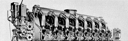
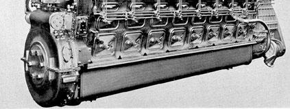
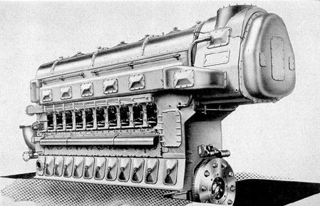
 developed an engine designed for the direct injection of liquid fuel into combustion chamber")
7 A. Diesel cycle : The ideal cycle for compression ignition (CI) engines Named after Rudolph Diesel (858 9) developed an engine designed for the direct injection of liquid fuel into combustion chamber in 897
8 Rudolf Christian Karl Diesel (858-9) 9) born on March 8, 858. His parents were Bavarian. Diesel pursued his education in England and at the Polytechnic School in Munich. He worked as a mechanic and parts designer for two years at the Sulzer Machine Works of Winterthur in Switzerland. joined the Linde Refrigeration Enterprises and worked as a refrigerator engineer.
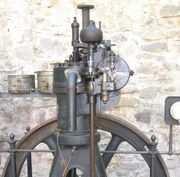
9 He envisioned an engine in which air is compressed to such a degree that there is an extreme rise in temperature.
10
11
12 When fuel is injected into the piston chamber with this air, the fuel is ignited by the high temperature of the air, exploding it, forcing the piston down. Diesel designed his engine in response to the heavy resource consumption and inefficiency of the steam engine, which only produced 2% efficiency.
13 A. Diesel cycle : The ideal cycle for CI engines An CI power cycle useful in many forms of automotive transportation, railroad engines, and ship power plants Replace (the spark plug + carburetor) in SI by fuel injector in CI engines. Spark plug Fuel injector Air-fuel mixture Fuel spray Gasoline engine Diesel engine
14 A. Diesel cycle : The ideal cycle for CI engines () Inlet valve open and fresh air is drawn into the cylinder (2) Temperature rise about the autoignition temperature of the fuel. () Intake compression Diesel fuel is sprayed into the combustion chamber. Evaporation, mixing, ignition and combustion of diesel fuel. In the later stages, expansion process occur. Combustion Exhaust (4) Burned gases is pushed out to the exhaust valve
15 A Diesel cycle : The ideal cycle for CI engines Processes: -2 Compression (s = Const) 2- Combustion (P = Const.) -4 Expansion (s = Const) 4- Exhaust (V = Const) P q in 2 4 T q out 2 q in 4 q out v (a) P-v diagram (b) T-s diagram Eliminates pre-ignition of the fuel-air mixture when compression ratio is high. s The combustion process in CI engines takes place over a longer interval and is approximated as constant-pressure heat addition process.
16 2.6 Diesel cycle : The ideal cycle for CI engines Energy balance for closed system: q q in in w = q q b out 2 out = = u w 2 2 = P ( v = ( h = q q 4 out 2 + ( u h 2 v ) u 2 2 ) ) + ( u = c = w+ u p ( T u 2 T qout = ( u4 u) = cv ( T4 T ) 4 4 = ( u u) 2 ) ) p = Constant 2 qout qin 4 V = Constant s η th,diesel = w q net in = q q out in = T4 T K( T T 2 ) = T kt ( T4 / T ) ( T / T ) 2 2
17 A. Diesel cycle : The ideal cycle for CI engines Define a new quantity r cutoff r c c V V ratio cylinder after combustion cylinder before combustion = V V 2 = v v 2 η th, diesel r k c = where r= k r k( rc ) v v 2 k rc k( r c ) > η th, > η otto th,diesel


18 A. Diesel cycle : The ideal cycle for CI engines As the cut off ratio decreases, increases η The th diesel engines operate at much higher r and usually more efficient than spark-ignition engines. The diesel engines also burn the fuel more completely since they usually operate at lower rpm than SI engines. CI engines operate on lower fuel costs.
19 A. Diesel cycle : The ideal cycle for CI engines At r c =, the Diesel and Otto cycles have the same efficiency. Physical implication for the Diesel cycle: No change in volume when heat is supplied. A high value of k compensates for this. For r c >, the Diesel cycle is less efficient than the Otto cycle.
20 Q : Example 9.45 An air standard Diesel cycle has a compression ratio of 6 and cut off ratio of 2. At beginning of the compression process, air is at 95kPa and 27 o C. Accounting for the variation of specific heat with temperature, determine a) Temperature after the heat additional process. b) Thermal efficiency c) The mean effective pressure Solution : Answer : a),724.8k b) 56.% c) 675.9kPa
21 Q Solution : P q in 2 4 q out T 2 (a) P-v diagram v (b) T-s diagram s q in 4 q out
22 Q
23 Dual cycle: A more realistic ideal cycle model for modern, high-speed compression ignition engine. P-v diagram of an ideal dual cycle.

24 A. Diesel cycle : The ideal cycle for CI engines The ideal Dual cycle The dual cycle is designed to capture some of the advantages of both the Otto and Diesel cycles. It it is a better approximation to the actual operation of the compression ignition engine.
25 A. Diesel cycle : The ideal cycle for CI engines The ideal Dual cycle p qin,v` qin,p 4 s = Constant 2 5 qout,v V
26 A. Diesel cycle : The ideal cycle for CI engines The ideal Dual cycle qin,v qin,p qout,p r = r c = V V 2 V V 4 V
27 Q2 : Example The compression cycle of an ideal dual cycle is 4. Air is at 00kPa and 00K at beginning of the compression process and at 2,200K at the end of heat addition process. Heat transfer process to air is take place partly at constant volume and partly at constant pressure and its amount to,520.4 kj/kg. Assume variable specific heat for air, determine the thermal efficiency of the cycle. 9-54
28 Q2 Solution 9-54
29 Q2
30 Q2
31 B. Stirling and Ericsson cycles

32 HISTORY OF STIRLING ENGINE REV.ROBERT STIRLING The Stirling engine was invented by Rev. Robert Stirling in 86. He was a Scottish minister. At that time, Stirling engines were recognized as a safe engine that could not explode like steam engines of that era often did.

33 B. External Combustion Engine : Stirling and Ericsson cycles This is the Stirling engine that he created in his era
34 B. External Combustion Engine : Stirling and Ericsson cycles He create a safer alternative to the steam engines of the time, Whose boilers often exploded due to the high pressure of the steam and the primitive materials of the time. Stirling engines convert heat (actually, any temperature differential) directly to movement. They use a displacer piston to move enclosed air back and forth between cold and hot reservoirs. most important invention was the "regenerator" or "economizer"

35 HISTORY OF ERICSSON ENGINE JOHN ERICSSON Ericsson was invented the "hot air engine" in 852 Used hot air instead of steam as a propellant Inspired by his earlier attempts of fume heat engines in Sweden.


36 B. External Combustion Engine : Stirling and Ericsson cycles
37 B. External Combustion Engine : Stirling and Ericsson cycles 86 he developed a screw mechanism for boat propulsion, which he called a "propeller. Then,Ericsson claimed priority of invention a tubular heat exchanger form of regeneration, Robert Stirling had in fact patented a similar system in Ericsson managed to persuade his financial backers to build the Caloric Ship "Ericsson. This engine was no success. In spite of this, Ericsson was awarded the Rumford Prize in 862.
38 B. External Combustion Engine : Stirling and Ericsson cycles Concept of Stirling Engine Energy in Hot source Cold air displace by piston Compression Energy out Expansion Hot air displace by piston Cold source
39 B. External Combustion Engine : Stirling and Ericsson cycles Concept of Stirling Engine Energy in Hot source Isochoric regeneration Isothermal Compression Energy out Isothermal Expansion Isochoric regeneration Cold source
40 B. External Combustion Engine : Stirling and Ericsson cycles Operation of a Stirling cycle (4) Isochoric regeneration qin () Isothermal compression Isothermal expansion () qout (2) Isochoric regeneration

41 B. External Combustion Engine : Stirling and Ericsson cycles
42 B. External Combustion Engine : Stirling and Ericsson cycles Indicated diagram for Stirling cycle p T qin qin 2 T H = constant 4 qout Regeneration 2 Regeneration T L = constant v 4 qout s


43 B. External Combustion Engine : Stirling and Ericsson cycles Operation of a Ericsson cycle
44 B. External Combustion Engine : Stirling and Ericsson cycles Indicated diagram for Ericsson cycle p T 4 qin qin 2 T H = constant qout Regeneration Regeneration T L = constant 2 v 4 qout s
45 B. External Combustion Engine : Stirling and Ericsson cycles
46 B. External Combustion Engine : Stirling and Ericsson cycles Thermal efficiency η th stirling = η = η = th Ericsson th Carnot T T L H Advantages. Potential for higher efficiency and better emission control 2. Suitable for variable fuels Disadvantages. Difficult to achieve in practice due to heat transfer
47 Example An ideal Stirling engine using helium as the working fluid operates between temperature limit 00K and 2,000K and pressure limits of 50 and,000 kpa. Assuming the mass of the helium used in the cycle is 0.2kg, determine : a) The thermal efficiency of the cycle. b) The amount of heat transfer rate in the regenerator. c) The work output per cycle. 9-64
48 B External Combustion Engine : Stirling and Ericsson cycles Indicated diagram for Stirling cycle p T qin qin 2 T H = constant 4 qout Regeneration 2 Regeneration T L = constant v 4 qout s
49 Example
50 C. Brayton cycle : The ideal cycle for gas-turbine engines
51 History The Brayton cycle is a constant-pressure cycle named after George Brayton (80 892), 892), the American engineer who developed it. It is also sometimes known as the Joule cycle. In 872, Brayton filed a patent for his "Ready Motor" which, unlike the Otto or Diesel cycles, used a separate compressor and expansion cylinder. Today the Brayton cycle is generally associated with gas turbines Like other internal combustion power cycles, The Brayton cycle is an open system, though for thermodynamic analysis it is conventionally assumed that the exhaust gases are reused in the intake, enabling analysis as a closed system.
52 C. Brayton cycle : The Ideal Cycle for Gas Turbine Engines Proposed by George Brayton around 870. Operate on an open cycle Application in commercial aircraft, military aircraft
53 C. Brayton cycle : The Ideal Cycle for Gas Turbine Engines Model The term Brayton cycle has more recently been given to the gas turbine engine. This also has three components: A gas compressor A burner (or combustion chamber) An expansion turbine


54 2.8 Brayton cycle : The Ideal Cycle for Gas Turbine Engines Operation of an open cycle gas turbine engine


55 C. Brayton cycle : The Ideal Cycle for Gas Turbine Engines Schematic diagram for the open cycle gas turbine engine
56 C. Brayton cycle : The Ideal Cycle for Gas Turbine Engines The air standard turbine cycle Open system modeled as a closed system - fixed with fixed mass flow. Air is the working fluid. Ideal gas assumptions are applied. Approximate the combustor as the high temperature source. Internally reversible processes.

 4- Isobaric")
57 C. Brayton cycle : The Ideal Cycle for Gas Turbine Engines Simplification of gas turbine engine in close cycle -2 Isentropic compression (in a compressor) 2- Isobaric heat addition -4 Isentropic expansion (in turbine) 4- Isobaric heat rejection
58 C. Brayton cycle : The Ideal Cycle for Gas Turbine Engines
59 C. Brayton cycle : The Ideal Cycle for Gas Turbine Engines Thermodynamics analysis Compressor w 2 = h know that w h 2 h = h = c p dt 2= wcomp = c p T ( T 2) Combustion chamber q q 2 in = = h c p h ( T T ) 2 2
60 C. Brayton cycle : The Ideal Cycle for Gas Turbine Engines Thermodynamics analysis Turbine w = h h = c p T ) 4 4 ( T4 w = c ( T T ) p 4 turb Heat exchanger q q 4 out = = h c p h ( T T ) 4 4
61 C. Brayton cycle : The Ideal Cycle for Gas Turbine Engines Thermodynamics analysis Thermal efficiency η η η th th th = = work net heat supplied c p = ( T ( T ( T 4 T c p 4 ( T T T 2 ) ) ) c = p T ( T 2 = w w ) 2 turb q q out in q T in ) comp
62 ( ) ( ) Processes- 2 and - 4 are isentropic, T P P T k k k k C. Brayton cycle : The Ideal Cycle for Gas Turbine Engines 2 )/ ( th Brayton where pressure ratio, P P r r T T P P P P T T p k k p = = = = = η
63 C. Brayton cycle : The Ideal Cycle for Gas Turbine Engines Thermodynamics analysis : Turbine efficiency T η η T T = = actual work isentropic work h h h h 4' 4 = T T T T 4' 4 = wa w 4 s
64 Thermodynamics analysis : Compressor efficiency T η η C C = = isentropic work actual work h h 2 2' h h = T T 2 2' T T = w w a
65 Thermodynamics analysis : actual thermal efficiency T η = η = w q net in ( T T4' ) ( T2' T ) ( T T 2 ') 4
66 work Compressor Turbine w turbine w net w compressor Back work
67 Thermodynamics analysis work Compressor Turbine w turbine w net w compressor Back work Work ratio r r w w = Back work ratio w T = T w turb comp ( T T4 ) ( T2 T ) r r w 4 bw bw turb = = T T w w 4 = comp turb = ( T ( T ( T 2 T T T 4 ) ) 4 )
/ k p Depends on")

68 η th Brayton =, r ( k )/ k p Depends on the pressure ratio and specific heat ratio
69 Example The open cycle gas turbine operate on Brayton cycle with pressure ratio 4.5/. Air enter the compressor at 2 0 C and heated to C at entry to the turbine. If mass flow rate is 40kg/min, Determine : a) Cycle efficiency b) Power output from the plant. k=.4, c p =.005kJ/kgK Data : r p =4.5, T =294K, T =05K, m=2.kg/s
70
71 Process -2, isentropic compression Process -4, isentropic expansion Consider kg of heat supply,
72 Heat rejection Net work output Cycle efficiency
73 Net work output per second
74 Example A gas turbine power plant operating on an ideal Brayton cycle has a pressure ratio of 8. The gas temperature is 00K at compressor inlet and,00k at turbine inlet. Utilizing the air standard assumption, determine : a) The gas temperature at exit of the compressor and turbine, (Answer = 770K) b) the back work ratio, (Answer = 0.40) c) The thermal efficiency (Answer = 0.426)
75 Solution Process -2, isentropic compression on ideal gas T 2 = at compressor exit Process -4, isentropic expansion on ideal gas T 4 = at Turbine exit
76 Pressure Drop.Pressure drop during heat addition and heat rejection process 2.Actual work input to compressor is more.actual work from the turbine is less
77 Thermodynamics analysis : Turbine efficiency T 4' 4' T a T work isentropic work actual T T h h w s w = = = = η η s T T T h h
78 Thermodynamics analysis : Compressor efficiency T η η C C = = isentropic work actual work h 2 h T 2 T = h h T T 2' 2' = w s w a
79 Thermodynamics analysis : actual thermal efficiency T η = η = w q ( T net in T4' ) ( T2' ( T T ) 2' T )
80 Example A gas turbine power plant operating on brayton cycle has a pressure ratio of 8. the gas temperature is 00K at compressor inlet and,00k at turbine inlet. Utilizing the air standard assumption, and assuming compressor efficiency of 80% and turbine efficiency is 85%, determine back work ratio
81 Solution Compressor Turbine Turbine
82 D. The Brayton cycle with regeneration
83 Cycle Improvements Regeneration Reduces heat input requirements and lowers heat rejected.
84 Regeneration is accomplished by preheating the combustor air with the exhaust gas from the turbine.
85 T,h Q H Q H W COMP W TURB Q C s Internal heat transfer, States 2 - x.
86 6 2 5 Q H 4 W COMP W TURB
87 Act and max heat transfer from the exhaust gas to air : q regen,act = h 5 h 2 q regen,max = h 5 h 2 = h 4 - h 2 q regen,act h 5 h 2 Effectiveness, = = q regen,max h 4 - h 2
88 The maximum benefit of regeneration is obtained when the exhaust temperature T 6 is brought to temperature T 2 by the regenerative heat exchanger or regenerator. Increase the thermal efficiency of the Brayton cycle Decrease the heat input (thus fuel) requirements Is use when the turbine exhaust temperature is higher than the compressor exit temperature
89 Example A gas turbine power plant operating on an Brayton cycle has a pressure ratio of 8. the gas temperature is 00K at compressor inlet and,00k at turbine inlet. Utilizing the air standard assumption, and assuming compressor efficiency of 80% and turbine efficiency is 85%, regenerator having effectiveness of 80% is is install, determine the thermal efficiency.
90 q regen,act h 5 h 2a Effectiveness, = = q regen,max h 4a - h 2a = 0.80, h 5 = 825.7kJ/kg q in = h - h 5 = 570.6kJ/kg
91 E. The Brayton cycle with intercooling, reheating and regeneration
92 Cycle Improvements Regeneration Reduces heat input requirements and lowers heat rejected. Inter-cooling Lowers mean temperature of the compression process Reheat Raises mean temperature of the heat addition process
93
94 T = T T6 = T8 P2 = P4 P = P
95
96 Decrease the total compression work Improve the back work ratio If the number of compression and expansion stages is increased, the ideal turbine cycle with intercooling, reheating and regeneration approaches the Ericsson cycle
97 T qin 2 Regeneration 4 qout s Multistage intercooling, reheat and regeneration gas turbine cycle The ideal Ericsson cycle
98 Thank You
Idealizations Help Manage Analysis of Complex Processes
 8 CHAPTER Gas Power Cycles 8-1 Idealizations Help Manage Analysis of Complex Processes The analysis of many complex processes can be reduced to a manageable level by utilizing some idealizations (fig.
In this lecture... Gas power cycles
 7 Lect-7 Gas power cycles In this lecture... he Carnot cycle and its significance Air-standard assumptions An oeriew of reciprocating engines Otto cycle: the ideal cycle for sparkignition engines Diesel
L34: Internal Combustion Engine Cycles: Otto, Diesel, and Dual or Gas Power Cycles Introduction to Gas Cycles Definitions
 Page L: Internal Combustion Engine Cycles: Otto, Diesel, and Dual or Gas Power Cycles Review of Carnot Power Cycle (gas version) Air-Standard Cycles Internal Combustion (IC) Engines - Otto and Diesel Cycles
Chapter 9 GAS POWER CYCLES
 Thermodynamics: An Engineering Approach Seventh Edition in SI Units Yunus A. Cengel, Michael A. Boles McGraw-Hill, 2011 Chapter 9 GAS POWER CYCLES Mehmet Kanoglu University of Gaziantep Copyright The McGraw-Hill
Chapter 9 GAS POWER CYCLES
 Thermodynamics: An Engineering Approach, 6 th Edition Yunus A. Cengel, Michael A. Boles McGraw-Hill, 2008 Chapter 9 GAS POWER CYCLES Copyright The McGraw-Hill Companies, Inc. Permission required for reproduction
Gas Power System. By Ertanto Vetra
 Gas Power System 1 By Ertanto Vetra Outlines Introduction Internal Combustion Engines Otto Cycles Diesel Cycles Gas Turbine Cycles Gas Turbine Based Combined Cycles Gas Turbines for Aircrafts Turbojets
CHAPTER I GAS POWER CYCLES
 CHAPTER I GAS POWER CYCLES 1.1 AIR STANDARD CYCLES Air standard cycles are used for comparison of thermal efficiencies of I.C engines. Engines working with air standard cycles are known as air standard
GAS POWER CYCLES. Dr Ali Jawarneh Department of Mechanical Engineering Hashemite University
 Chapter 9 GAS POWER CYCLES Dr Ali Jawarneh Department of Mechanical Engineering i Hashemite University 2 Objectives Evaluate the performance of gas power cycles for which h the working fluid remains a
(v) Cylinder volume It is the volume of a gas inside the cylinder when the piston is at Bottom Dead Centre (B.D.C) and is denoted by V.
 Cylinder volume It is the volume of a gas inside the cylinder when the piston is at Bottom Dead Centre (B.D.C) and is denoted by V.") UNIT II GAS POWER CYCLES AIR STANDARD CYCLES Air standard cycles are used for comparison of thermal efficiencies of I.C engines. Engines working with air standard cycles are known as air standard engines.
UNIT II GAS POWER CYCLES AIR STANDARD CYCLES Air standard cycles are used for comparison of thermal efficiencies of I.C engines. Engines working with air standard cycles are known as air standard engines.
Internal Combustion Engines
 Internal Combustion Engines Reading Problems 8-3 8-7 8-35, 8-45, 8-52 Definitions 1. spark ignition: a mixture of fuel and air is ignited by a spark plug applications requiring power to about 225 kw (300
Week 10. Gas Power Cycles. ME 300 Thermodynamics II 1
 Week 10 Gas Power Cycles ME 300 Thermodynamics II 1 Today s Outline Gas power cycles Internal combustion engines Four-stroke cycle Thermodynamic cycles Ideal cycle ME 300 Thermodynamics II 2 Gas Power
Chapter 9. Two important areas of application for thermodynamics GAS POWER CYCLES. Objectives
 Chapter 9 GAS POWER CYCLES Two important areas of application for thermodynamics are power generation and refrigeration. Both are usually accomplished by systems that operate on a thermodynamic cycle.
BASIC CONSIDERATIONS IN POWER CYCLE ANALYSIS THERMODYNAMICS CHAPTER 9
 08.04.3. HERMODYNAMICS CHAPER 9 Gas power cycles Lecturer Axel GRONIEWSKY, PhD 5 th of February08 Most power-producing devices operate on cycles. Complexity of actual cycles are high idealizationsare required
Class Notes on Thermal Energy Conversion System
 Class Notes on Thermal Energy Conversion System For the students of Civil & Rural 3 rd semester Ramesh Khanal Assistant Professorr Nepal Engineering College Bhaktapur, Nepal 2015 Course Structure MEC 209.3:
Heat engine. Heat engine
 Heat engine Device that transforms heat into work. It requires two energy reservoirs at different temperatures An energy reservoir is a part of the environment so large wrt the system that its temperature
Power Cycles. Ideal Cycles, Internal Combustion
 Gas Power Cycles Power Cycles Ideal Cycles, Internal Combustion Otto cycle, spark ignition Diesel cycle, compression ignition Sterling & Ericsson cycles Brayton cycles Jet-propulsion cycle Ideal Cycles,
Combustion engines. Combustion
 Combustion engines Chemical energy in fuel converted to thermal energy by combustion or oxidation Heat engine converts chemical energy into mechanical energy Thermal energy raises temperature and pressure
Engine Cycles. T Alrayyes
 Engine Cycles T Alrayyes Introduction The cycle experienced in the cylinder of an internal combustion engine is very complex. The cycle in SI and diesel engine were discussed in detail in the previous
(a) then mean effective pressure and the indicated power for each end ; (b) the total indicated power : [16]
![(a) then mean effective pressure and the indicated power for each end ; (b) the total indicated power : [16]](/thumbs/79/80273804.jpg "(a) then mean effective pressure and the indicated power for each end ; (b) the total indicated power : [16]") Code No: R05220304 Set No. 1 II B.Tech II Semester Regular Examinations, Apr/May 2007 THERMAL ENGINEERING-I ( Common to Mechanical Engineering and Automobile Engineering) Time: 3 hours Max Marks: 80 Answer
Code No: R05220304 Set No. 1 II B.Tech II Semester Regular Examinations, Apr/May 2007 THERMAL ENGINEERING-I ( Common to Mechanical Engineering and Automobile Engineering) Time: 3 hours Max Marks: 80 Answer
Chapter 8 Production of Power from Heat
 Chapter 8 Production of Power from Heat Different sources of power, such as solar energy (from sun), kinetic energy from atmospheric winds and potential energy from tides. The most important source of
Prepared by: Dr. Assim Adaraje
 Air-standard cycles Prepared by: Dr. Assim Adaraje CH. 2 ۱ Cold-air-standard assumptions: When the working fluid is considered to be air with constant specific heats at room temperature (25 C). Air-standard
UNIT 1 GAS POWER CYCLES
 THERMAL ENGINEERING UNIT 1 GAS POWER CYCLES Air Standard Cycles - Otto, Diesel, Dual, Brayton cycle with intercooling, reheating and regeneration- Calculation of airstandard efficiency and mean effective
Thermodynamic Cycles. Alicia Ma. Esponda Cascajares
 Thermodynamic Cycles Alicia Ma. Esponda Cascajares Power Cycles Cycles which convert a heat input into a mechanical work output. Power cycles can be divided according to the type of heat engine they seek
η th W = Q Gas Power Cycles: Working fluid remains in the gaseous state through the cycle.
 Gas Power Cycles: Gas Power Cycles: Working fluid remains in the gaseous state through the cycle. Sometimes useful to study an idealised cycle in which internal irreversibilities and complexities are
VALVE TIMING DIAGRAM FOR SI ENGINE VALVE TIMING DIAGRAM FOR CI ENGINE
 VALVE TIMING DIAGRAM FOR SI ENGINE VALVE TIMING DIAGRAM FOR CI ENGINE Page 1 of 13 EFFECT OF VALVE TIMING DIAGRAM ON VOLUMETRIC EFFICIENCY: Qu. 1:Why Inlet valve is closed after the Bottom Dead Centre
Combustion Systems What we might have learned
 Combustion Systems What we might have learned IMechE ADSC, 6 December 2012 Chris Whelan Contents Engines Big & Small Carnot, Otto & Diesel Thermodynamic Cycles Combustion Process & Systems Diesel & Otto
Process 1-2: Reversible adiabatic compression process. Process 2-3: Reversible isothermal heat addition
 Vapor Power Cycles Process 1-2: Reversible adiabatic compression process from P1 to P2. Process 2-3: Reversible isothermal heat addition process at constant temperature TH. Process 3-4: Reversible adiabatic
Thermodynamics cycles can be classified into different categories depending on fluid used or the different processes:
 Classification of thermodynamics cycles Thermodynamics cycles can be classified into different categories depending on fluid used or the different processes: Gas and vapor cycles - Gas cycle: the working
A REVIEW ON STIRLING ENGINES
 A REVIEW ON STIRLING ENGINES Neeraj Joshi UG Student, Department of Mechanical Engineering, Sandip Foundation s Sandip Institute of Technology and Research Centre,Mahiravani, Nashik Savitribai Phule Pune
UNIT IV INTERNAL COMBUSTION ENGINES
 UNIT IV INTERNAL COMBUSTION ENGINES Objectives After the completion of this chapter, Students 1. To know the different parts of IC engines and their functions. 2. To understand the working principle of
The Internal combustion engine (Otto Cycle)
") The Internal combustion engine (Otto Cycle) The Otto cycle is a set of processes used by spark ignition internal combustion engines (2-stroke or 4-stroke cycles). These engines a) ingest a mixture of fuel
The Internal combustion engine (Otto Cycle) The Otto cycle is a set of processes used by spark ignition internal combustion engines (2-stroke or 4-stroke cycles). These engines a) ingest a mixture of fuel
2013 THERMAL ENGINEERING-I
 SET - 1 II B. Tech II Semester, Regular Examinations, April/May 2013 THERMAL ENGINEERING-I (Com. to ME, AME) Time: 3 hours Max. Marks: 75 Answer any FIVE Questions All Questions carry Equal Marks ~~~~~~~~~~~~~~~~~~~~~~~~
USO4CICV01/US04CICH02:
 Natubhai V. Patel College of Pure & Applied Sciences S. Y. B.Sc. Semester-4 Industrial chemistry/ IC (Vocational) USO4CICV0/US04CICH02: Chemical Plant Utilities UNIT 5 Internal combustion engine In an
8.21 The Physics of Energy Fall 2009
 MIT OpenCourseWare http://ocw.mit.edu 8.21 The Physics of Energy Fall 2009 For information about citing these materials or our Terms of Use, visit: http://ocw.mit.edu/terms. 8.21 Lecture 11 Internal Combustion
UNIT 2 POWER PLANTS 2.1 INTRODUCTION 2.2 CLASSIFICATION OF IC ENGINES. Objectives. Structure. 2.1 Introduction
 UNIT 2 POWER PLANTS Power Plants Structure 2.1 Introduction Objectives 2.2 Classification of IC Engines 2.3 Four Stroke Engines versus Two Stroke Engines 2.4 Working of Four Stroke Petrol Engine 2.5 Working
MEB THERMAL ENGINEERING - I QUESTION BANK UNIT-I PART-A
 MEB 420 - THERMAL ENGINEERING - I QUESTION BANK UNIT-I Each question carries 1 mark. PART-A 1. Define temperature. 2. Define intensive property 3. Explain the term absolute zero of temperature 4. State
Content : 4.1 Brayton cycle-p.v. diagram and thermal efficiency. 4Marks Classification of gas turbines.
 Content : 4.1 Brayton cycle-p.v. diagram and thermal efficiency. 4Marks Classification of gas turbines. 4.2 Construction and working of gas turbines i) Open cycle ii) Closed cycle gas Turbines, P.V. and
Hours / 100 Marks Seat No.
 17529 14115 3 Hours / 100 Seat No. Instructions (1) All Questions are Compulsory. (2) Answer each next main Question on a new page. (3) Illustrate your answers with neat sketches wherever necessary. (4)
Introduction to I.C Engines CH. 1. Prepared by: Dr. Assim Adaraje
 Introduction to I.C Engines CH. 1 Prepared by: Dr. Assim Adaraje 1 An internal combustion engine (ICE) is a heat engine where the combustion of a fuel occurs with an oxidizer (usually air) in a combustion
Comparison of Air-Standard Atkinson, Diesel and Otto Cycles with Constant Specific Heats
 Comparison of Air-Standard Atkinson, Diesel and Otto Cycles with Constant Specific Heats Sethi Upasna Vijay 1, Mansha Kumari 2 1 Assistant Professor, Mechanical Engineering Department, Vadodara Institute
2. Discuss the effects of the following operating variables on detonation
 Code No: RR220303 Set No. 1 II B.Tech II Semester Regular Examinations, Apr/May 2006 THERMAL ENGINEERING-I ( Common to Mechanical Engineering and Automobile Engineering) Time: 3 hours Max Marks: 80 Answer
Scheme G Sample Question Paper Course Name : Diploma in Automobile Engineering Course Code : AE
 Sample Question Paper Semester : Fourth Marks : 100 Time: 03 Hours Q1.A. Attempt any SIX a. State different types of ideal gas processes 12 Marks b. Define dryness fraction and degree of superheat. c.
ME2301 THERMAL ENGINEERING L T P C OBJECTIVE:
 ME2301 THERMAL ENGINEERING L T P C 3 1 0 4 OBJECTIVE: To integrate the concepts, laws and methodologies from the first course in thermo dynamics into analysis of cyclic processes To apply the thermodynamic
OBJECTIVE: GENERAL ASPECTS ABOUT ENGINES MECHANISM:
 LANDMARK UNIVERSITY, OMU-ARAN LECTURE NOTE 3 COLLEGE: COLLEGE OF SCIENCE AND ENGINEERING DEPARTMENT: MECHANICAL ENGINEERING Course code: MCE 211 Course title: Introduction to Mechanical Engineering Credit
Assignment-1 Air Standard Cycles
 Assignment-1 Air Standard Cycles 1. What do u mean by air standard cycle? List assumptions for air standard cycle & give reasons why air standard cycle differs from actual cycle. 2. Derive an equation
 SET - 1 II B. Tech II Semester Regular/Supplementary Examinations, April/May-2017 THERMAL ENGINEERING-I (Mechanical Engineering) Time: 3 hours Max. Marks: 70 Note: 1. Question Paper consists of two parts
Kul Internal Combustion Engine Technology. Definition & Classification, Characteristics 2015 Basshuysen 1,2,3,4,5
 Kul-14.4100 Internal Combustion Engine Technology Definition & Classification, Characteristics 2015 Basshuysen 1,2,3,4,5 Definitions Combustion engines convert the chemical energy of fuel to mechanical
Homogeneous Charge Compression Ignition (HCCI) Engines
 Engines") Homogeneous Charge Compression Ignition (HCCI) Engines Aravind. I. Garagad. Shri Dharmasthala Manjunatheshwara College of Engineering and Technology, Dharwad, Karnataka, India. ABSTRACT Large reductions
Homogeneous Charge Compression Ignition (HCCI) Engines Aravind. I. Garagad. Shri Dharmasthala Manjunatheshwara College of Engineering and Technology, Dharwad, Karnataka, India. ABSTRACT Large reductions
Noble Group of Institutions, Junagadh. Faculty of Engineering Department of Mechanical Engineering
 Semester:1 st Subject: Elements of Mechanical Engineering (2110006) Faculty: Mr. Ishan Bhatt Year: 2017-18 Class: Comp. & IT Ele TUTORIAL 1 INTRODUCTION Q.1 Define: Force, Work, Pressure, Energy, Heat
FUNDAMENTALS OF POWER PLANTS. Asko Vuorinen
 FUNDAMENTALS OF POWER PLANTS Asko Vuorinen 1 Engine cycles Carnot Cycle Otto Cycle Diesel Cycle Brayton Cycle Rankine Cycle Combined Cycles 2 Carnot Engine 3 Carnot Cycle 4 Carnot Cycle, continued Ideal
ME Thermal Engineering Question Bank
 ME2301 - Thermal Engineering Question Bank UNIT I GAS POWER CYCLES Otto, Diesel, Dual, Brayton cycles, Calculation of mean effective pressure, and air standard efficiency -Actual and theoretical PV diagram
Gas Turbine Power Plant Mr.B.Ramesh, M.E.,(Ph.D)
") Gas Turbine Power Plant By Mr.B.Ramesh, M.E.,(Ph.D) Research Scholar, CEG, Anna University, Chennai. Associate Professor of Mechanical Engineering, St. Joseph s College of Engineering, Jeppiaar Trust,
Gas Turbine Power Plant By Mr.B.Ramesh, M.E.,(Ph.D) Research Scholar, CEG, Anna University, Chennai. Associate Professor of Mechanical Engineering, St. Joseph s College of Engineering, Jeppiaar Trust,
INTERNAL COMBUSTION ENGINE (SKMM 4413)
") INTERNAL COMBUSTION ENGINE (SKMM 4413) Dr. Mohd Farid bin Muhamad Said Room : Block P21, Level 1, Automotive Development Centre (ADC) Tel : 07-5535449 Email: mfarid@fkm.utm.my HISTORY OF ICE History of
INTERNAL COMBUSTION ENGINE (SKMM 4413) Dr. Mohd Farid bin Muhamad Said Room : Block P21, Level 1, Automotive Development Centre (ADC) Tel : 07-5535449 Email: mfarid@fkm.utm.my HISTORY OF ICE History of
Template for the Storyboard stage
 Template for the Storyboard stage Animation can be done in JAVA 2-D. Mention what will be your animation medium: 2D or 3D Mention the software to be used for animation development: JAVA, Flash, Blender,
Heat Transfer in Engines. Internal Combustion Engines
 Heat Transfer in Engines Internal Combustion Engines Energy Distribution Removing heat is critical in keeping an engine and lubricant from thermal failure Amount of energy available for use: Brake thermal
ENGINES ENGINE OPERATION
 ENGINES ENGINE OPERATION Because the most widely used piston engine is the four-stroke cycle type, it will be used as the example for this section, Engine Operation and as the basis for comparison in the
Scheme - G. Sample Test Paper-I. Course Name : Diploma in Mechanical Engineering Course Code : ME Semester : Fifth Subject Title : Power Engineering
 Sample Test Paper-I Marks : 25 Time:1 hour Q1. Attempt any Three 3X3=9 a) Define i) Mean Effective Pressure ii) Piston Speed iii) Swept Volume b) Draw Carnot cycle on P-V and T-S Diagram c) State the need
GYANMANJARI INSTITUTE OF TECHNOLOGY (GMIT) SUBJECT: ELEMENTS OF MECHANICAL ENGINEERING Assignment Ch 1
 SUBJECT: ELEMENTS OF MECHANICAL ENGINEERING Assignment Ch 1") 1. 3. GYANMANJARI INSTITUTE OF TECHNOLOGY (GMIT) Assignment Ch 1 A steel ball having mass of 10 kg and a specific heat of 460 J/kg K is heated from 50 o C to 200 o C. Determine the heat required. In a
1. 3. GYANMANJARI INSTITUTE OF TECHNOLOGY (GMIT) Assignment Ch 1 A steel ball having mass of 10 kg and a specific heat of 460 J/kg K is heated from 50 o C to 200 o C. Determine the heat required. In a
Thermodynamics II MIDTERM MECH 351/2 Fall 06 CONCORDIA UNIVERSITY FACULTY OF ENGINEERING AND COMPUTER SCIENCE DEPARTMENT OF MECHANICAL ENGINEERING
 Thermodynamics II MIDTERM MEH 35/ Fall 06 ONORDIA UNIVERSITY FAULTY OF ENGINEERING AND OMPUTER SIENE DEPARTMENT OF MEHANIAL ENGINEERING Student s Name: I.D.: I. [50 points] A steam power plant operates
ME3264: LAB 9 Gas Turbine Power System
 OBJECTIVE ME3264: LAB 9 Gas Turbine Power System Professor Chih-Jen Sung Spring 2013 A fully integrated jet propulsion system will be used for the study of thermodynamic and operating principles of gas
VETRI VINAYAHA COLLEGE OF ENGINEERING AND TECHNOLOGY DEPARTMENT OF MECHANICAL ENGINEERING ME6404 THERMAL ENGINEERING
 VETRI VINAYAHA COLLEGE OF ENGINEERING AND TECHNOLOGY DEPARTMENT OF MECHANICAL ENGINEERING ME6404 THERMAL ENGINEERING UNIT I - GAS POWER CYCLES 1. What is a thermodynamic cycle? Thermodynamic cycle is defined
SAMPLE STUDY MATERIAL
 IC Engine - ME GATE, IES, PSU 1 SAMPLE STUDY MATERIAL Mechanical Engineering ME Postal Correspondence Course Internal Combustion Engine GATE, IES & PSUs IC Engine - ME GATE, IES, PSU 2 C O N T E N T 1.
Principles of Engine Operation. Information
 Internal Combustion Engines MAK 4070E Principles of Engine Operation Prof.Dr. Cem Soruşbay Istanbul Technical University Information Prof.Dr. Cem Soruşbay İ.T.Ü. Makina Fakültesi Motorlar ve Taşıtlar Laboratuvarı
ADVANTAGES OF GTE s Weight reduction of 70% Simplicity Reduced manning requirements Quicker response time Faster Acceleration/deceleration Modular rep
 USES OF GAS TURBINE ENGINES Aircraft Engines Main Propulsion Arleigh Burke, Tichonderoga, Spruance, Oliver Hazard Perry LCACS, Pegasus Auxiliary Applications Electric generators ADVANTAGES OF GTE s Weight
SIDDHARTH INSTITUTE OF ENGINEERING & TECHNOLOGY :: PUTTUR (AUTONOMOUS) QUESTION BANK UNIT I I.C ENGINES
 QUESTION BANK UNIT I I.C ENGINES") SIDDHARTH INSTITUTE OF ENGINEERING & TECHNOLOGY :: PUTTUR UNIT I I.C ENGINES 1 (a) Explain any six types of classification of Internal Combustion engines. (6M) (b) With a neat sketch explain any three
SIDDHARTH INSTITUTE OF ENGINEERING & TECHNOLOGY :: PUTTUR UNIT I I.C ENGINES 1 (a) Explain any six types of classification of Internal Combustion engines. (6M) (b) With a neat sketch explain any three
Powertrain Efficiency Technologies. Turbochargers
 Powertrain Efficiency Technologies Turbochargers Turbochargers increasingly are being used by automakers to make it possible to use downsized gasoline engines that consume less fuel but still deliver the
Internal Combustion Engines
 Introduction Lecture 1 1 Outline In this lecture we will learn about: Definition of internal combustion Development of the internal combustion engine Different engine classifications We will also draw
Page 2. (a) (i) Show that during the change AB the gas undergoes an isothermal change.
 (i) Show that during the change AB the gas undergoes an isothermal change.") Q1.The Carnot cycle is the most efficient theoretical cycle of changes for a fixed mass of gas in a heat engine. The graph below shows the pressure volume (p V) diagram for a gas undergoing a Carnot cycle
Q1.The Carnot cycle is the most efficient theoretical cycle of changes for a fixed mass of gas in a heat engine. The graph below shows the pressure volume (p V) diagram for a gas undergoing a Carnot cycle
KINGS COLLEGE OF ENGINEERING DEPARTMENT OF MECHANICAL ENGINEERING. Question Bank. UNIT-I THERMODYNAMIC CYCLES Part-A (2 Marks)
") KINGS COLLEGE OF ENGINEERING DEPARTMENT OF MECHANICAL ENGINEERING Question Bank Sub. Code/Name: ME1351 - THERMAL ENGINEERING Year/Sem: III/VI 1. What is a thermodynamic cycle? UNIT-I THERMODYNAMIC CYCLES
KINGS COLLEGE OF ENGINEERING DEPARTMENT OF MECHANICAL ENGINEERING Question Bank Sub. Code/Name: ME1351 - THERMAL ENGINEERING Year/Sem: III/VI 1. What is a thermodynamic cycle? UNIT-I THERMODYNAMIC CYCLES
Design and Analysis of Stirling Engines. Justin Denno Advised by Dr. Raouf Selim
 Design and Analysis of Stirling Engines Justin Denno Advised by Dr. Raouf Selim Abstract The Stirling engines being researched here are the acoustic engines and the Alpha-V engine. The acoustic engine
Internal Combustion Engines
 Air and Fuel Induction Lecture 3 1 Outline In this lecture we will discuss the following: A/F mixture preparation in gasoline engines using carburetion. Air Charging technologies: Superchargers Turbochargers
Approved by AICTE, Government of India & affiliated to Dr. A.P.J. Abdul Kalam Technical University, Lucknow Department of Mechanical Engineering
 Experiment No. - 1 Object: Study and working of four stroke petrol engine. Apparatus Required: S. No. Name of Apparatus Specifications Model of Four stroke petrol engine NA Figure 1: Working of four stroke
Internal Combustion Engine. Prepared by- Md Ferdous Alam Lecturer, MEE, SUST
 Internal Combustion Engine Prepared by- Md Ferdous Alam Lecturer, MEE, SUST What is an Engine? -a machine designed to convert one form of energy into mechanical energy Two types of engines : 1. Internal
Unit WorkBook 4 Level 4 ENG U13 Fundamentals of Thermodynamics and Heat Engines UniCourse Ltd. All Rights Reserved. Sample
 Pearson BTEC Levels 4 Higher Nationals in Engineering (RQF) Unit 13: Fundamentals of Thermodynamics and Heat Engines Unit Workbook 4 in a series of 4 for this unit Learning Outcome 4 Internal Combustion
MTX221. Session 53. Sessie 53 DRYWINGS-KRINGLOPE (GAS-FASE) POWER CYCLES (GAS PHASE) Dr. Jaco Dirker. These slides also appear on Click-UP
 POWER CYCLES (GAS PHASE) Dr. Jaco Dirker. These slides also appear on Click-UP") Ses.53-1 MX221 Sessie 53 DRYWINGS-KRINGLOPE (GAS-FASE) Session 53 POWER CYCLES (GAS PHASE) Dr. Jaco Dirker hese slides also appear on Click-UP Hierdie skyfies verskyn ook op Click-UP 8 th edition / 8e
Ses.53-1 MX221 Sessie 53 DRYWINGS-KRINGLOPE (GAS-FASE) Session 53 POWER CYCLES (GAS PHASE) Dr. Jaco Dirker hese slides also appear on Click-UP Hierdie skyfies verskyn ook op Click-UP 8 th edition / 8e
ADDIS ABABA UNIVERSITY INSTITUTE OF TECHNOLOGY
 1 INTERNAL COMBUSTION ENGINES ADDIS ABABA UNIVERSITY INSTITUTE OF TECHNOLOGY MECHANICAL ENGINEERING DEPARTMENT DIVISON OF THERMAL AND ENERGY CONVERSION IC Engine Fundamentals 2 Engine Systems An engine
IC ENGINES. Differences between SI and CI engines: Petrol is fuel, which has a high self ignition temperature
 IC ENGINES SI Engines work at constant volume. They have a compression ratio of around 6-10. But CI engines work at constant pressure and has a compression ratio of 16-20. In four stroke engines, one power
INTRODUCTION OF FOUR STROKE ENGINE
 INTRODUCTION OF FOUR STROKE ENGINE Engine: An engine is motor which converts chemical energy into mechanical energy Fuel/petrol engine: A petrol engine (known as a gasoline engine in North America) is
The 4 Stroke Diesel Cycle
 The 4 Stroke Diesel Cycle Nickolaus Otto invented the 4 stroke cycle in 1862. More details of how the four stroke spark ignition cycle works, together with pictures of Otto's first engines can be found
EFFICIENCY INCREASE IN SHIP'S PRIMAL ENERGY SYSTEM USING A MULTISTAGE COMPRESSION WITH INTERCOOLING
 THERMAL SCIENCE, Year 2016, Vol. 20, No. 2, pp. 1399-1406 1399 EFFICIENCY INCREASE IN SHIP'S PRIMAL ENERGY SYSTEM USING A MULTISTAGE COMPRESSION WITH INTERCOOLING by Petar LANDEKA and Gojmir RADICA* Faculty
Thermodynamics [ENGR 251] [Lyes KADEM 2007]
![Thermodynamics [ENGR 251] [Lyes KADEM 2007]](/thumbs/77/75921316.jpg "Thermodynamics [ENGR 251] [Lyes KADEM 2007]") hermodynamics [ENGR 25] [yes KADEM 2007] II. Carnot Cycle he Carnot cycle was first proposed 824, by Sadi Carnot. he terest the cycle is largely theoretical, as no practical Carnot cycle enge has yet been
hermodynamics [ENGR 25] [yes KADEM 2007] II. Carnot Cycle he Carnot cycle was first proposed 824, by Sadi Carnot. he terest the cycle is largely theoretical, as no practical Carnot cycle enge has yet been
THERMAL ENGINEERING. SHIBIN MOHAMED Asst. Professor Dept. of Mechanical Engineering Al Ameen Engineering College.
 THERMAL ENGINEERING SHIBIN MOHAMED Asst. Professor Dept. of Mechanical Engineering Al Ameen Engineering College Al- Ameen Engg. College 1 Steam Engine: Definition A steam engine is a heat engine that converts
I.C ENGINES. CLASSIFICATION I.C Engines are classified according to:
 I.C ENGINES An internal combustion engine is most popularly known as I.C. engine, is a heat engine which converts the heat energy released by the combustion of the fuel taking place inside the engine cylinder
 Important Instructions to examiners: 1) The answers should be examined by key words and not as word-to-word as given in the model answer scheme. 2) The model answer and the answer written by candidate
Applied Thermodynamics Internal Combustion Engines
 Applied Thermodynamics Internal Combustion Engines Assoc. Prof. Dr. Mazlan Abdul Wahid Faculty of Mechanical Engineering Universiti Teknologi Malaysia www.fkm.utm.my/~mazlan 1 Coverage Introduction Operation
COVENANT UNIVERSITY NIGERIA TUTORIAL KIT OMEGA SEMESTER PROGRAMME: MECHANICAL ENGINEERING
 COVENANT UNIVERSITY NIGERIA TUTORIAL KIT OMEGA SEMESTER PROGRAMME: MECHANICAL ENGINEERING COURSE: MCE 320 DISCLAIMER The contents of this document are intended for practice and leaning purposes at the
DEPARTMENT OF MECHANICAL ENGINEERING ME ENGINEERING THERMODYNAMICS TWO MARKS QUESTION AND ANSWER
 DEPARTMENT OF MECHANICAL ENGINEERING ME 6301- ENGINEERING THERMODYNAMICS TWO MARKS QUESTION AND ANSWER 1. Define the term thermal engineering. Ans: Thermal engineering is the science that deals with the
Emission from gasoline powered vehicles are classified as 1. Exhaust emission 2. Crank case emission 3. Evaporative emission. Table 1.
 Introduction: Main three types of automotive vehicle being used 1. Passenger cars powered by four stroke gasoline engines 2. Motor cycles, scooters and auto rickshaws powered mostly by small two stroke
Gas Turbine Power Plant
 Gas Turbine Power Plant Dr. M. Zahurul Haq Professor Department of Mechanical Engineering Bangladesh University of Engineering & Technology (BUET) Dhaka-1000, Bangladesh zahurul@me.buet.ac.bd http://teacher.buet.ac.bd/zahurul/
If you like us, please share us on social media. The latest UCD Hyperlibrary newsletter is now complete, check it out.
 Sign In Forgot Password Register ashwenchan username password Sign In If you like us, please share us on social media. The latest UCD Hyperlibrary newsletter is now complete, check it out. ChemWiki BioWiki
density ratio of 1.5.
 Problem 1: An 8cyl 426 ci Hemi motor makes 426 HP at 5500 rpm on a compression ratio of 10.5:1. It is over square by 10% meaning that it s stroke is 10% less than it s bore. It s volumetric efficiency
Internal combustion engines can be classified in a number of different ways: 1. Types of Ignition
 Chapter 1 Introduction 1-3 ENGINE CLASSIFICATIONS Internal combustion engines can be classified in a number of different ways: 1. Types of Ignition 1 (a) Spark Ignition (SI). An SI engine starts the combustion
Internal Combustion Engines
 Internal Combustion Engines The internal combustion engine is an engine in which the burning of a fuel occurs in a confined space called a combustion chamber. This exothermic reaction of a fuel with an
CHEN 205: Project. Stirling Engine
 CHEN 205: Project Stirling Engine 11 August 2014 Samuel Adams, Ashley Bender, Matthew Carlin, Monica Cuerno BACKGROUND Robert Stirling was a Scotsman and clergyman born in Cloag, Perthshire, on October
Comparative Study Of Four Stroke Diesel And Petrol Engine.
 Comparative Study Of Four Stroke Diesel And Petrol Engine. Aim: To study the construction and working of 4- stroke petrol / diesel engine. Theory: A machine or device which derives heat from the combustion
PERIODIC-COMBUSTION GAS TURBINE ENGINES (UNITS)
") Gas urbine Engines (Units) - V.E.Mihaltzev and V.D.Molyov PERIODIC-COMBUSION GAS URBINE ENGINES (UNIS) V.E.Mihaltzev and V.D.Molyov Moscow State echnical University n.a. Bauman, Russia Keywords: gas turbine
Gas urbine Engines (Units) - V.E.Mihaltzev and V.D.Molyov PERIODIC-COMBUSION GAS URBINE ENGINES (UNIS) V.E.Mihaltzev and V.D.Molyov Moscow State echnical University n.a. Bauman, Russia Keywords: gas turbine
Investigators: C. F. Edwards, Associate Professor, Mechanical Engineering Department; M.N. Svreck, K.-Y. Teh, Graduate Researchers
 Development of Low-Irreversibility Engines Investigators: C. F. Edwards, Associate Professor, Mechanical Engineering Department; M.N. Svreck, K.-Y. Teh, Graduate Researchers This project aims to implement
Which are the four important control loops of an spark ignition (SI) engine?
 engine?") 151-0567-00 Engine Systems (HS 2017) Exercise 1 Topic: Lecture 1 Johannes Ritzmann (jritzman@ethz.ch), Raffi Hedinger (hraffael@ethz.ch); October 13, 2017 Problem 1 (Control Systems) Why do we use control
151-0567-00 Engine Systems (HS 2017) Exercise 1 Topic: Lecture 1 Johannes Ritzmann (jritzman@ethz.ch), Raffi Hedinger (hraffael@ethz.ch); October 13, 2017 Problem 1 (Control Systems) Why do we use control
CHAPTER 9 GAS POWER CYCLES PART 1. MOHD KAMAL ARIFFIN, Faculty of Mechanical Engineering, UTM, Skudai
 CHAPER 9 GAS POWER CYCLES PAR MOHD KAMAL ARIFFIN, Faculty of Mechanical Engineering, UM, Sudai OPIC : GAS POWER CYCLES - PAR INRODUCION What is IC Engine? An internal combustion engine is a thermal system
Ultra-High-Efficiency Engines: Integration, Optimization, Realization
 Ultra-High-Efficiency Engines: Integration, Optimization, Realization Chris F. Edwards Greg Roberts, BJ Johnson, Rebecca Pass, Adelaide Calbry-Muzyka, Julie Blumreiter, Mark Donohue, Carol Regalbuto, John