Rakopoulos, C. D., Kosmadakis, G. M., Demuynck, J., De Paepe, M. and Verhelst, S.
|
|
|
- Erick Ross
- 5 years ago
- Views:
Transcription
1 biblio.ugent.be The UGent Institutional Repository is the electronic archiving and dissemination platform for all UGent research publications. Ghent University has implemented a mandate stipulating that all academic publications of UGent researchers should be deposited and archived in this repository. Except for items where current copyright restrictions apply, these papers are available in Open Access. This item is the archived peer-reviewed author-version of: A combined experimental and numerical study of thermal processes, performance and nitric oxide emissions in a hydrogen-fueled spark-ignition engine. Rakopoulos, C. D., Kosmadakis, G. M., Demuynck, J., De Paepe, M. and Verhelst, S. In: International Journal of Hydrogen Energy 36(8): , To refer to or to cite this work, please use the citation to the published version: Rakopolous, C.D. et al. (2011). A combined experimental and numerical study of thermal processes, performance and nitric oxide emissions in a hydrogen-fueled spark-ignition engine. International Journal of Hydrogen Energy 36 (8), pp Doi: /j.ijhydene
2 A COMBINED EXPERIMENTAL AND NUMERICAL STUDY OF THERMAL PROCESSES, PERFORMANCE AND NITRIC OXIDE EMISSIONS IN A HYDROGEN- FUELED SPARK-IGNITION ENGINE (COVER PAGE) REVISED by C.D. RAKOPOULOS : Professor of Internal Combustion Engines Director of I.C. Engines Laboratory Dipl.Ing., M.Sc., D.I.C., Ph.D. (Imperial College of Science, Technology and Medicine, University of London) M. ASME, M. N.Y.Acad.Sci., M. SAE, M. ASCE G.M. KOSMADAKIS : Research Assistant, Dipl.Ing., M.Sc. (NTUA) Ph.D. Candidate J. DEMUYNCK* : Research Assistant, Dipl.Ing., M.Sc. (GHENT) Ph.D. Candidate M. DE PAEPE* : Professor of Applied Thermodynamics and Heat Transfer, Dipl.Ing., M.Sc., Ph.D. (GHENT) S. VERHELST* : Professor of Alternative Fuels for Internal Combustion Engines, Dipl.Ing., M.Sc., Ph.D. (GHENT) Internal Combustion Engines Laboratory Thermal Engineering Department, School of Mechanical Engineering National Technical University of Athens (NTUA) 9 Heroon Polytechniou St., Zografou Campus, Athens, Greece Tel.: , Fax: cdrakops@central.ntua.gr *Department of Flow, Heat and Combustion Mechanics Ghent University Sint-Pietersnieuwstraat 41, B-9000 Ghent, Belgium Submitted for publication to the International Journal of HYDROGEN ENERGY, Elsevier Science Editor-in-Chief: Professor T. Nejat Veziroglu
3 A combined experimental and numerical study of thermal processes, performance and nitric oxide emissions in a hydrogen-fueled sparkignition engine C.D. Rakopoulos a,, G.M. Kosmadakis a, J. Demuynck b, M. De Paepe b, S. Verhelst b a Internal Combustion Engines Laboratory, Thermal Engineering Department, School of Mechanical Engineering, National Technical University of Athens, 9 Heroon Polytechniou St., Zografou Campus, Athens, Greece b Department of Flow, Heat and Combustion Mechanics, Ghent University, Sint-Pietersnieuwstraat 41, B-9000 Ghent, Belgium ABSTRACT This work concerns the study of a spark-ignition engine fueled with hydrogen, using both measured and numerical data at various conditions, focusing on the combustion efficiency, the heat transfer phenomena and heat loss to the cylinder walls, the performance, as well as the nitric oxide (NO) emissions formed, when the fuel/air and compression ratio are varied. For the investigation of the heat transfer mechanism, the local wall temperatures and heat flux rates were measured at three locations of the cylinder liner in a CFR engine. These fluxes can provide a reliable estimation of the total heat loss through the cylinder walls and of the hydrogen flame arrival at specific locations. Together with the experimental analysis, the numerical results obtained from a validated in-house CFD code were utilized for gaining a more complete view of the heat transfer mechanism and the hydrogen combustion efficiency for the various cases examined. The performance of the CFR engine is then identified, since the calculated cylinder pressures are compared with the measured ones, from which performance and heat release rates are calculated and discussed. Further, NO emission studies have been accomplished, with the calculated results not only being compared with the measured exhaust NO ones, but also further processed for conducting an in-depth investigation of the dependence of NO production on the spatial distribution of in-cylinder gas temperature. It is revealed that for lower fuel/air ratio the burned gas temperature is held at low level and the heat loss ratio is quite low. As the load increases and stoichiometric mixtures are used, the wall and in-cylinder gas temperatures increase substantially, together with the heat loss and the NO emissions, owing to the high hydrogen combustion velocity and the consequent high rate of temperature rise. The combustion efficiency is slightly increased, but the indicated efficiency is decreased due to higher heat loss. Keywords: hydrogen; spark-ignition engine; combustion efficiency; heat transfer; NO emissions. Corresponding author. Tel.: ; Fax: address: cdrakops@central.ntua.gr (C.D. Rakopoulos). 1
4 Nomenclature A c p calibration constant in turbulent flame speed expression specific heat capacity under constant pressure, J/kg K k turbulent kinetic energy (per unit mass), m 2 /s 2 LHV H 2 lower heating value of hydrogen, kj/kg m H 2 inlet hydrogen mass, kg n ex n i n u n w exhaust heat ratio indicated efficiency (gross) combustion efficiency heat loss (to the walls) ratio P pressure, N/m 2 Pr Prandtl number q w wall heat flux, W/m 2 Q B Q ex Q n real heat of combustion, J exhaust heat, J net heat release, J Q H 2 theoretical heat of combustion, J Q w wall heat loss, J Q volumetric heat release rate due to combustion, J/s m 3 c S cr S h S t T T w u l u t u T source term due to crevice flows source term of the enthalpy equation source term time, s temperature, K wall temperature, K laminar flame speed, m/s turbulent flame speed, m/s friction velocity, m/s u rms turbulent velocity, m/s u velocity vector, m/s V cylinder volume, m 3 W gi gross indicated work, J 2
5 W P y y + pumping losses, J distance of the computational node from the wall, m non-dimensional distance from the wall Greek symbols Γ γ λ diffusion coefficient, kg/m s ratio of specific heat capacities relative air-to-fuel ratio ν kinematic viscosity, m 2 /s ρ density, kg/m 3 τ c τ l τ t characteristic conversion time, s laminar kinetics time, s turbulent mixing time, s τ w local wall shear stress, kg/m s 2 φ fuel-to-air equivalence ratio or (simply) equivalence ratio generalized variable Abbreviations ABDC after bottom dead center ATDC after top dead center BBDC before bottom dead center BTDC before top dead center CFD computational fluid dynamics CFR Cooperative Fuel Research CR compression ratio 0 CA degrees of crank angle EVO IT IVC MBT NO NO x PFI exhaust valve opening ignition timing inlet valve closure minimum spark advance for best torque nitric oxide nitrogen oxides port fuel injection 3
6 PISO rpm SI TDC WOT pressure implicit splitting of operators revolutions per minute spark-ignition top dead center wide-open throttle 1. Introduction One important research aspect of the automotive industry is the improvement of the engine efficiency and the exploitation of the use of alternative fuels. Within this field, appropriate experimental test-benches are constructed, in order to investigate the combustion process and performance of the promising spark-ignition engines running on hydrogen under different operating conditions and strategies [1-6], together with the various in-cylinder processes taking place [7]. For this task many important parameters are measured, such as the cylinder pressure, emissions, wall temperatures etc., and processed to evaluate the engine performance [8,9]. Apart from the experimental investigations of hydrogen-fueled spark-ignition engines, numerical tools are also developed [7,10-13] in order to constitute an additional weapon in the detailed investigation of the various processes on those kind of engines. Especially, the results obtained from computational fluid dynamics (CFD) codes [7,13] can further assist to appraise the engine performance, since they can describe in a more fundamental way the in-cylinder phenomena [14], such as the flame kernel development, and the heat and mass transfer. In the present study both experimental and numerical investigations have been accomplished simultaneously, in order to identify with detail some critical processes taking place in a hydrogen-fueled, spark-ignition engine. More specifically, measurements have been conducted on a Cooperative Fuel Research (CFR) engine at two compression ratios and three equivalence ratios at minimum spark advance for best torque (MBT), in order to appraise the heat transfer through the cylinder boundaries together with the engine s performance and emissions. Also, a validated in-house CFD code has been applied to simulate the functioning of that engine under the same operating conditions, in order to have a more detailed view of the in-cylinder processes. Both results (experimental and numerical) are combined, with a final task to examine the combustion efficiency, the thermal processes, the performance, and the spatial production of nitric oxide emissions for this engine. 4
7 2. Experimental data 2.1. Test engine The experimental data used in the present study concern measurements on a CFR engine, operating at a constant engine speed equal to 600 rpm. It is equipped with port fuel injection (PFI) and has a variable compression ratio. The load of the engine is altered with the variation of the equivalence ratio (quality load control), while all measurements are conducted at wide-open throttle (WOT). Fuel injection and ignition timing are controlled by a MoTeC M4Pro unit. The main specifications of this engine are given in Table 1. The measured data that will be elaborated here concern the inlet mass flow rates of air and hydrogen, the cylinder pressure traces, the NO/NO x emissions, the inlet and exhaust gas temperatures and the wall temperatures and heat flux rates at three locations (the heat flux measurements were carried out with a Vatell HFM-7 sensor). The data are measured for different operating conditions, when varying the compression ratio (CR) with values 8 or 9, and the fuel-to-air equivalence ratio φ (i.e. the actual fuelto-air ratio divided by its stoichiometric value) in the range , or correspondingly λ in the range (λ=1/φ is the relative air-to-fuel ratio). The investigated compression ratios are kept quite low, in order for the piston not to cover the heat flux sensors, since the latter are installed at the cylinder liner, and the center of the sensor is located 9 mm lower than the cylinder head. A more detailed description of the measuring equipment and the experimental uncertainty can be found in Ref. [2], while a general overview of the test setup with the notation of the measurement positions and the location of the spark-plug is shown in Fig Conditions investigated The current study focuses on the hydrogen combustion efficiency, the heat transfer mechanism and the performance of the spark-ignition engine, combined with the NO exhaust emissions. Some of the most important parameters influencing the relevant phenomena are the compression ratio (CR) and the equivalence ratio φ [2]. Especially the latter one plays a dominant role on the peak heat flux in hydrogen engines, since it has been shown that the heat loss greatly increases, when the engine operates with stoichiometric mixtures, compared to running on methane [2,8]. Moreover, the ignition 5
8 timing (IT) has a great influence on the heat loss, as described in Ref. [15], but this parameter is not investigated here, since the spark-timing has been set to MBT for all cases examined. Concerning the effect of the equivalence ratio and compression ratio on the wall temperatures, the measured wall temperature history at location P3 of the cylinder liner (see Fig. 1) during the compression and expansion strokes can be observed in Fig. 2, where as the engine mixtures approaches stoichiometry the local wall temperature is radically increased. Moreover, the sharp increase of the wall temperature just after the spark-timing is higher for richer mixtures. The effect of compression ratio is less clear, since it is coupled with the effect of the variation of the ignition timing. It is interesting to notice that the wall temperatures are unexpectedly slightly decreasing when the compression ratio increases, which is due to a later spark-timing that is selected to be equal to the MBT for each case. The same trend is also noticed for the measured wall temperature histories at the other two measurement locations, P2 and P4 (not shown here). The same findings hold true concerning the influence of the equivalence ratio and the compression ratio on the measured peak heat flux at location P2 of the cylinder liner (see Fig. 1), as shown in Fig. 3. It becomes evident that the greatest effect is due to the equivalence ratio, and not to the variation of the compression ratio. The latter has a small effect on the peak heat flux, since for every case examined different spark-timings have been chosen (equal in every case to MBT). It should be mentioned here that the same trend is also observed for the other two measurement locations, P3 and P4 (not shown here). 3. Numerical model 3.1. CFD model The firing version of the CFD code developed by the first two authors can simulate three-dimensional curvilinear domains, using the finite volume method in a collocated grid. It has been validated in a previous published work [16] in comparison to measured data, showing that it is capable of simulating adequately the power cycle of hydrogenfueled spark-ignition engines. The in-house CFD code developed incorporates the RNG k ε turbulence model [17] with some slight modifications to introduce the compressibility of a fluid in generalized 6
9 coordinates, as described in Ref. [18]. It solves the transport equations for the conservation of mass, momentum, chemical species and energy, Eq. (1), as suggested in Ref. [19]. t u S Scr The second source term shown in Eq. (1), (S cr ) represents the effect of the phenomenological crevice model used, incorporated in the CFD code [20]. Furthermore, for the turbulence model the source terms of the turbulent kinetic energy and its dissipation are the same as in Ref. [21]. Further details of the in-house CFD model used, concerning the pressure-correction algorithm used (PISO) [18], the turbulence model, the mesh generation model, the crevice model, as well as a detailed evaluation and validation of the developed CFD model under both motoring and firing conditions, can be found in previous published papers by the first two authors [16,20-22]. (1) 3.2. Heat transfer model In the present study the wall-heat flux correlation developed in a previous work of the first two authors [21] is used for the simulation of the heat transfer mechanism. Its formulation is based on a compressible version of the standard law-of-the-wall [23], and it includes the unsteady pressure term, which has been also shown in [24] to give more accurate results. In this study an additional term, the volumetric heat release rate due to c combustion ( Q ) has been also included, in order to capture the increase of the wallheat flux due to combustion phenomena in the computational cells adjacent to the walls, as also suggested in [24]. The wall heat flux (in W/m 2 ), which is inserted into the source term of the energy equation (S h ) for the boundary cells, is shown in Eq. (2). This expression is used for every non-dimensional distance from the wall ( y yu T ), where u T 4 τ ρ C 1/ k y ν is the friction velocity (with C μ equal to , according to the w μ RNG k ε turbulence model [17]). q W ρ u c T ln T T p 1 ln y w 40 dp ν y Q T c dt u T Pr 1 1 ln Pr Pr (2) 7
10 Further details concerning the development, implementation and validation of this heat transfer model used in the in-house CFD code, can be found in previous works of the first two authors [21,25] Combustion model In the next subsections the combustion model developed by the first two authors will be briefly presented, as applied for the simulation of hydrogen-fueled, spark-ignition engines. Only its basic features will be given, since its detailed presentation is provided in a previous publication [16] Laminar and turbulent burning velocities (ignition and main stage of combustion) In the developed combustion model, a correlation of the hydrogen laminar flame speed (u l ) is used [16]. After investigating various correlations for engine relevant conditions found in the literature [26], which additionally include stretch effects, a recently published correlation was implemented in the combustion model [27]. This correlation is used, in order to track the computational cells in which the flame has propagated during the ignition phase [16]. This is accomplished with the calculation of the flame kernel radius, by approximating the flame propagation velocity with the laminar flame speed, since the characteristic dimension of the flame is considered to be smaller than the prevailing turbulence eddies. The ignition energy supplied by the spark-plug is simulated by adding energy to the computational cell located at the point where the spark plug is placed (see Fig. 1). The spark duration is equal to 5 degrees CA and the supplied spark energy to the combustible mixture is 10 mj, being a quite low value, since it incorporates also the heat energy loss to the electrodes; no additional model has been implemented to simulate this process, due to the great uncertainty of the exact shape, temperature and transient effects near the spark electrodes. The end of the ignition process and the transition to the turbulent combustion is determined by the time instant that the flame kernel radius exceeds a specific constant value (critical radius) equal to 4 mm [7]. More details concerning the incorporation of the laminar flame speed to the combustion model and the description of the ignition model can be found in Ref. [16]. The laminar flame speed is used not only during the ignition process, when the initial flame kernel approximately propagates with its laminar flame speed [7], but also during 8
11 the turbulent flame development phase, when in the expression of the turbulent burning velocity the correlation of the laminar flame speed is inserted. In the developed combustion model the turbulent flame speed (u t ) is used, in order to track the computational cells in which the flame has propagated during the main stages of combustion after the ignition phase. The expression incorporated is the one proposed by Zimont/Lipatnikov and Chomiak [28,29], where only one calibration constant A needs to be tuned. This tuning process has been accomplished in the evaluation study of the combustion model [16], where the calibration constant has been found to be equal to 0.8. In the present study this constant holds the same value for every case examined. Further details concerning the implementation of this turbulent burning velocity expression in the combustion model developed and the description of the turbulent flame development phase can be found in Ref. [16] Reaction rate calculation The basic sub-model incorporated in the developed CFD code for the calculation of the reaction rates is the characteristic conversion time-scale method. This sub-model uses a characteristic time-scale ( c ), which is the sum of the laminar conversion time ( l ) and the turbulent mixing time ( t ), and dictates to what extent the combustible gas of each computational cell has reached its chemical equilibrium in a predefined time step. This methodology is followed for the calculation of the reaction rates of all chemical species taken into consideration here, namely H 2, O 2, N 2, H 2 O, H, O, N, and OH, except for the nitric oxide (NO), which is kinetically controlled and its reaction rate will be discussed in the next sub-section. The methodology followed originates from the work of Abraham et al. [30], which has gone through some major improvements ever since [31] and has been also extended to other types of engines [32,33]. Recently, it has been formulated for the simulation of hydrogen-fueled spark-ignition engines and validated against experimental data, while further details concerning the calculation of the reaction rates with the use of the characteristic conversion time-scale method can be found in Ref. [16] NO formation modeling 9
12 It has been shown that the reaction rate of the nitric oxide (NO) is kinetically controlled, governed primarily by three kinetic reactions known as the extended Zeldovich mechanism [34]. The methodology followed is the same as the one presented in detail in [35]. The most usual set of constants for the reaction rates of the three chemical equations considered is also used in the present study, which is the one reported in Ref. [34]. Nevertheless, these constants were derived for hydrocarbon fuels, and so their uncertainty (which is already quite high) increases when they are applied for the calculation of the nitric oxide reaction rates in the case of a fuel being carbon-free [13]. 4. Results and discussion 4.1. Test cases examined The operating conditions of the CFR engine investigated in the current study concern the variation of the compression ratio and the equivalence ratio. For all cases examined a WOT has been used, the spark-timing is set to its MBT value, and the engine speed is kept constant at 600 rpm. Table 2 gives the matrix of all test cases examined Computational details In the present study some initial and boundary conditions are provided from the experimental data, such as the pressure at IVC, the inlet air and hydrogen flow rates, and the wall temperatures. For the rest of the required conditions, reliable estimations are used. The initial flow field is calculated by considering an initial swirl ratio at IVC equal to 1.5, since the inlet valve is unshrouded [33]. The initial turbulence properties are the same as the ones derived from a relevant work concerning the same engine [33], and are held constant for every case examined here, since the engine speed is kept constant as well. More specifically, the initial turbulent velocity (u ) at IVC is equal to 5.16 m/s, giving a rms turbulent velocity at TDC equal to around 0.86 m/s, although the latter value slightly changes with engine load and compression ratio. The initial gas temperature at IVC is varied from 370 K to 400 K, as the mixture becomes richer (for both compression ratios). The estimation of the residual gas mass fraction plays an important role in the value of the laminar flame speed. At IVC the initial mixture is composed of H 2, O 2, N 2, and H 2 O, and the mass content of each of these species is affected by the residual gas 10
13 mass fraction. Estimations concerning the values of residual gas and its trend are obtained from the works reported in [36,37], combined with the measured air and hydrogen inlet flow rates. No overlapping period of the inlet and exhaust valves exists in this specific engine, thus making the estimation of the residual gas rather simpler. Concerning the computational mesh used, previous relevant studies [20,21], together with a parametric study using the firing version of the developed CFD code, have shown that the most reliable mesh, providing adequate accuracy and keeping the required CPU time relative low, is the one having (40x40x40) grid lines along each axis respectively. The computational mesh at the beginning of the simulations (IVC) is shown in Fig. 4 (for CR=9). The grid-spacing along the x- and y-axis is very uniform and equal to around 2 mm, while the initial grid-spacing along the z-axis (axial) is around 3 mm. The methodology of adding or removing mesh layers, according to the piston s movement, is the same as the one described in Ref. [21]. The computational time step used is kept low and equal to CA, since it has been shown that it is small enough to provide time-step independent solutions [21], even for low rotational speeds. During the combustion period, initiating from the ignition timing and afterwards, the time step is further decreased and becomes equal to CA, as in Ref. [7]. This tactics is followed, in order to increase the accuracy of the computational results, but also to increase the stability of the code, since during each time step the variation of the cylinder pressure and temperature is large, especially for the higher load cases. Finally, the only calibration constant used in the in-house CFD code exists in the expression of the turbulent flame speed, and retains the value A=0.8 (as mentioned in subsection above) for all cases examined Investigation of combustion efficiency The investigation begins with the hydrogen combustion efficiency for every case examined. This parameter, as is defined in the present study, includes three major losses, which decrease the theoretical heat of combustion ( QH m 2 H LHV 2 H ): 2 1. Hydrogen loss to the crankcase (blow-by). Around 6-7% of the initial trapped mass at IVC enters the crevices during the compression stroke and the early combustion period, and only a fraction of the initial trapped mass re-enters the combustion 11
14 chamber during the expansion stroke (around 4%). The rest is lost as blow-by, although for hydrogen engines the geometry of the piston-rings is adapted [26]. 2. Since the dissociation of the combustion products is also taken into consideration, the theoretical heat of combustion is decreased, due to the production of the species OH, O, H, N, and NO during the combustion period, especially at increased temperatures (high load). 3. The hydrogen combustion is not complete, since a low concentration of (molecular) hydrogen can be traced in the exhaust gas, especially in the case of leaner mixtures [38]. The above three combustion inefficiency mechanisms can all be included in a general expression for the hydrogen combustion efficiency. More specifically, Eq. (3) is used for its calculation [15]. n Q Q B B u (3) QH m LHV 2 H2 H2 where Q B the real heat of combustion calculated directly from the CFD code, H 2 Q the theoretical heat of combustion, m H the inlet hydrogen mass, which is trapped in the 2 cylinder at the beginning of the compression stroke (based on the measured hydrogen flow rate), and LHV H the lower heating value of hydrogen equal to 120 MJ/kg 2 H2 [1]. An alternative technique for estimating the combustion efficiency is with the use of the measured oxygen and hydrogen concentrations in the exhaust gas, according to the methodology reported in [38]. This is not followed here, since additional losses are encountered (such as the dissociation of combustion products), which are all included in a more general expression, as in Eq. (3). Another important reason for not following that method is due to the low values of hydrogen concentration in the exhaust gas (for some cases the measured value is equal to zero), in which case the use of this method could provide inaccurate results, such as a combustion efficiency equal to 100% in the case of no hydrogen traced by the measurement equipment in the exhaust gas (especially for stoichiometric mixtures). According to Ref. [38], as the equivalence ratio is increased approaching stoichiometry, the combustion efficiency is increased as well. In other words, as the combustion duration decreases and the process approaches the ideal constant volume combustion close to TDC, the combustion efficiency increases as also reported in [12]. 12
15 This trend is also depicted here, as shown in Fig. 5, where the combustion efficiency together with the theoretical heat of combustion (derived from the measured value of available hydrogen per engine cycle) can be observed for all cases examined. The combustion efficiency takes high values, approaching 100% especially for the richer mixtures, as expected. This is in accordance to the almost untraceable unburned hydrogen concentration at the exhaust for the rich mixtures, meaning that the actual unburned hydrogen is lower than the sensitivity of the measurement equipment. Additionally, for higher compression ratio the combustion efficiency slightly decreases, which can be explained by the retarded spark-timing for the cases with the compression ratio equal to 9 (at TDC for the leanest mixture to 14 0 CA ATDC for the richest one). The theoretical heat of combustion follows exactly the same trend for the cases considered here. In a more detailed attempt to identify the relative influence of each one of the three loss mechanisms, namely the unburned hydrogen in the exhaust gas, the hydrogen loss in the blow-by gas and the dissociation of combustion products, contributing to the combustion inefficiency, further processing of the numerical results has been accomplished. By doing so, strategies for increasing the combustion efficiency could focus on each mechanism exclusively, as the load and compression ratio varies, in order to maximize the overall efficiency as well. Fig. 6 shows the relative contribution of each of the three mechanisms in the overall combustion process, for all cases examined. As depicted, the unburned hydrogen in the exhaust gas is actually zero for the stoichiometric mixtures for both compression ratios, while it is substantially increased for lower loads, as was also experimentally observed in Ref. [39]. This is due to the combustion duration increase for leaner mixtures, where the prevailing burned gas temperature is much lower, causing an incomplete hydrogen oxidation. Concerning the hydrogen lost in the blow-by gas, for leaner mixtures this mass fraction is just slightly lower. One would expect to be substantially lower due to the steep pressure rise for the rich mixtures, forcing more mass to enter the crevices (for a short period though). On the other hand, the initial trapped mass at IVC for the lean mixtures is higher (due to the lower initial mixture temperature). The combined result of these two contradictory trends is for the combustion inefficiency to be only slightly higher at richer mixtures. Finally, the dissociation of combustion products is observed mainly at high temperatures [40]. Therefore, as expected, the combustion of lean mixtures produces 13
16 fewer dissociated species contrary to richer mixtures, where in the latter cases the combustion temperature reaches 2800 K. This brings a decrease in the real heat of combustion due to the production of OH, O, H, N, and NO. The dissociation values calculated here are significant lower than the ones found in the work of Obermair et al. [41], since the burned temperatures are lower, due to a retarded spark-timing and lower compression ratio. Fig. 6 also shows that the general trend of the three mechanisms, when varying the compression ratio, is the same although the ignition timing is substantially varied. The overall difference of the combustion efficiency when varying the compression ratio, seems to be caused by the inefficiency of the dissociation, since only this value is increased at higher compression ratio, while the other two inefficiencies have similar values Investigation of heat transfer In this subsection the local wall heat fluxes of the CFR engine will be presented first, concerning both measured and calculated data obtained from the CFD code. The scope is, first, to evaluate the CFD code and its capabilities to predict adequately in-cylinder heat transfer phenomena. This is accomplished by comparing the calculated local wallheat fluxes with the measured values at three locations of the cylinder liner for all cases examined. As known, the measurement of local wall-heat fluxes in the combustion chamber of internal combustion engines requires special techniques and care [42]. This is guaranteed also here, as described in Ref. [2], where an overview is provided of the relevant measurement methods with emphasis on their use in hydrogen-fueled engines. The present study then proceeds with the calculation of the cumulative heat loss to the cylinder walls and eventually with the estimation of the fraction of the real combustion heat that is actually lost to the cylinder walls, during the closed part of the engine cycle for each case examined [8]. Fig. 7 shows the comparison of the calculated local wall heat fluxes with the measured ones for compression ratio equal to 8 (cases 1-3 of Table 2), while Fig. 8 for compression ratio equal to 9 (cases 4-6 of Table 2). It should be mentioned that the measured heat fluxes at locations P2 and P4 (see Fig. 1) have very close values, since their distance from the spark-plug is the same and the timing that the flame front reaches these locations is virtually the same. Some slight differences observed to these measured data are due to the slightly different spatial turbulent and velocity distribution, 14
17 which causes a different flame speed. On the other hand, the calculated results cannot capture this discrepancy, since uniform values for the turbulent kinetic energy, its dissipation rate, and the velocity profiles have been used in the initial conditions. Therefore, the calculated heat fluxes at locations P2 and P4 have almost the same values during the engine cycle. For this reason, the comparison will be limited only to the heat fluxes at locations P2 and P3 in the cylinder liner of the CFR engine. The comparison reveals that the CFD code developed can adequately calculate the peak heat flux, together with the timing of the flame arrival at the locations where the probes are installed (at P2 and P3 locations and P4 as well, which is not shown here), for both compression ratios and all equivalence ratios under study, although some small discrepancies are observed especially at the P3 location for the leaner mixtures. The prediction of the local wall heat flux at P3 location is not as accurate as at P2 location for every case examined, which can be attributed to the slight different wall temperature at these two locations (the boundary temperature is locally and temporally constant at the whole cylinder wall in the CFD code) and to the spatial uniform initial flow and turbulence field used in the CFD code, as described in the previous paragraph. The underprediction of the heat fluxes during the late expansion stroke that was noticed in previous studies [16,25] is kept low and the performance of the wall-function formulation during this time period has been substantially increased, due to the incorporation of the combustion term (Eq. (2)). Additionally, during the compression stroke the calculated local wall heat fluxes are close to the measured data. After revealing the capability of the developed CFD code to calculate with good accuracy the heat transfer to the cylinder walls for the cases examined, the calculated mean wall heat losses will be provided next. These are actually spatial-averaged values over the entire cylinder wall, from which a cumulative heat loss can then be calculated. Fig. 9 shows the averaged heat loss for all cases examined, based on the calculations obtained from the CFD code. For the richer mixtures the peak heat loss is much higher than the ones for part-load operation (φ=0.75 and 0.50). This has to do with the specific properties of hydrogen, and most importantly with its high laminar flame speed. The combustion period in that case lasts for fewer degrees CA, causing high gas temperatures and an intense heat transfer process, due to the rapid heat release rate of the fuel. From the calculated mean heat loss to the cylinder walls, the cumulative heat transfer can then be derived during the closed part of the engine cycle. The calculated results 15
18 are presented in Table 3, where the increased values of the total heat loss for the full load operation (φ=1) can be identified for both compression ratios. In the same Table is also shown the cumulative heat loss derived from the mean measured values of the local heat fluxes. This kind of comparison of the numerical results with the measured values is not straightforward, since the measured values are based only on the local heat fluxes at three locations. Nevertheless, this procedure can provide an estimation of the error introduced when such strategies are followed [43]. When the compression ratio is increased (Cases 4-6) the total heat loss remains almost constant, instead of increasing. This has to do with the different spark-timing used for each case, set equal to MBT; as shown in Refs. [2,15], the heat loss is substantially affected by this timing. Concerning the heat loss ratio, it is defined as the ratio of the calculated cumulative heat loss to the cylinder walls over the real heat of combustion according to [8], and it is given by Eq. (4). This ratio is shown in Fig. 10 for all cases examined here, together with the real heat of combustion. Q w nw (4) QB The variation of the heat loss ratio with the equivalence ratio is less pronounced here than in the one described in Ref. [15], since smaller differences are observed as the load changes. Nevertheless, the trend of increasing the heat loss ratio as the mixture becomes richer is correctly captured. The same also holds true for the variation of compression ratio, having a minor influence on the heat loss ratio. On the other hand, the real heat of combustion remains almost constant as the compression ratio varies, and follows strictly the theoretical heat of combustion (see Fig. 5). This has to do, to a great extent, with the spark-timing selected in each case (equal to MBT) Investigation of performance In this section the performance of the CFR engine will be investigated, concerning the cylinder pressure traces, the net heat release rate, and the gross indicated work, using both measured and numerical data Investigation of pressure history 16
19 Beginning with the pressure traces, in Fig. 11 is shown the comparison of the calculated cylinder pressure history with the measured one for all cases examined. It is interesting to note the increased peak pressure for the stoichiometric gas mixtures in contrast to the leaner mixtures, together with the steeper pressure rise during the early stages of the combustion period just after the spark-timing for both compression ratios. Generally speaking, the comparison of the predicted data with the measured ones is good, since for every case considered the peak pressure and its timing are well captured, except from the leaner mixtures, where some small discrepancies are observed. These can be partly attributed to the correlation of the laminar flame speed used in the CFD code, and to the lower heat loss calculated during the beginning of combustion, as can be observed in Figs. 7 and 8. It should be mentioned that in the correlation used, the fitting of its constants to reproduce the actual measured data involves some expected error [44], which close to its lower (and maybe upper) validity limit might become important, as is the case here for φ=0.5 (lower validity limit equal to φ=0.4). Additionally, the calculated cylinder pressure just before the ignition-timing is very close to the measured value (due to a reliable wall-heat function formulation and crevice model used), and the calculated pressure during the expansion stroke matches in good terms the measured one. The latter aspect is of high significance, since in a previous study [16] it has been shown that the calculated pressure during this time period was over-predicted, due to a lower calculated wall heat loss. But this drawback has been further investigated, and its solution is based on the incorporation of the heat of combustion in the expression of the wall-heat flux (see Eq. (2)), in order for the performance to be better calculated Investigation of net heat release rate As known, concerning the study of the combustion process in internal combustion engines, a very important means to analyze combustion characteristics is the calculation and analysis of heat release rates according to actual measurements of pressures in the chamber [45]. Using the numerical and measured data, the net heat release rate can be calculated for the present hydrogen-fueled spark-ignition engine [2]. The experimental net heat release rate was calculated based on the cylinder pressure traces (following a single-zone approach), according to [2], using Eq. (5). dqn dqb dqw γ dv 1 dp p V (5) dθ dθ dθ γ 1 dθ γ 1 dθ 17
20 where Q B the real heat of combustion (given in a previous sub-section), Q w the wall heat loss, V the instantaneous cylinder volume, and γ the ratio of specific heat capacities taken equal to a constant value of 1.35 [2]. For all cases examined the net heat release rate is presented in Fig. 12, where the experimental net heat release rate is calculated as above, and the numerical one directly from CFD code. In this figure, it is shown that the numerical data can capture in good terms the effects of variation of the compression ratio and equivalence ratio. The most important finding drawn from this figure is the combustion duration, which for hydrogen is small and, as the mixture becomes richer, it is further decreased (partly explaining the increased combustion efficiency for the richer mixtures), together with an intense heat loss just after the end of combustion (at the point where the net heat release rate becomes negative). As the mixture becomes leaner the peak net heat release rate is substantially decreased, which is observed for both compression ratios, while after the end of combustion almost zero values prevail Investigation of gross indicated work Since the focus is on the closed part of the cycle (from IVC until EVO), the gross indicated work will be calculated as well, using Eq. (6), in order to better identify the performance of the engine. EVO gi IVC W p dv (6) Fig. 13 shows the gross indicated work for all cases examined, depicting the comparison of the numerical with the measured data. The trend is well captured from the calculations, when varying the compression ratio, but most importantly when varying the equivalence ratio. Also, for all cases considered, there is a good match of the calculated data with the measured ones in absolute values as well, especially for the higher compression ratio, which is within the experimental uncertainty (2.5%) [2]. Moreover, the gross indicated work is actually constant when the compression ratio increases. This has to do with the spark-timing selected (equal to MBT for both compression ratios) Investigation of the thermal energy of the exhaust gas The energy flow that is not transformed into work or heat loss to the cylinder walls, is actually the exhaust heat of the engine. This value can be defined as follows [15]: 18
21 Q ex Q Q W (7) B w gi In Table 4 is shown the exhaust heat as calculated for every case examined, using Eq. (7), together with the exhaust heat ratio, which is defined as n Q Q ; it is actually the fraction of the real heat of combustion lost to the exhaust. The exhaust heat as well as the exhaust heat ratio is calculated directly from the CFD code. In Table 4 are also shown the measured exhaust gas temperatures for every case examined, which can provide an indication of the thermal content of exhaust gas. As the equivalence ratio is increased, the exhaust heat ratio is decreased for both compression ratios, having though a small variation. Owing to the high heat loss during the expansion stroke, a great portion of the real heat of combustion has been lost to the cylinder walls, decreasing the exhaust heat, which is nevertheless maintained at high values [8]. This can be confirmed by the relatively small variation of the measured exhaust gas temperatures for variable equivalence ratio. ex ex B 4.7. Investigation of efficiency The scope here is to identify how the available chemical energy of the fuel is transformed into work and which portion of it is actually lost, as heat loss to the combustion chamber walls and to the exhaust gas, combined with the combustion inefficiency mechanisms, described previously. This task demands as prerequisites the appraisal of the combustion efficiency, and the performance of the hydrogen-fueled spark-ignition engine under investigation, which were presented in the previous subsections. The indicated efficiency (gross) combines all these energy flows, and is calculated by Eq. (8): n i Wgi Wgi (8) Q m LHV H 2 H 2 H 2 The indicated efficiency is shown in Fig. 14 for all cases examined, comparing the measured with the calculated data. It is observed that as the mixture becomes leaner the efficiency is radically increased, which is correlated to some extent with the lower heat loss, and additionally related to the specific gas properties of the mixture (e.g. the specific heat capacity), while the increase of the compression ratio brings an increase to the indicated efficiency only for the two leaner mixtures. Moreover, the comparison of the calculated indicated efficiency with the measured one is relatively good, and the trend is well captured from the CFD results. 19
22 The above analysis focuses on the closed part of the cycle, since it is representative of the efficiency and the performance of the entire engine cycle. This is quite true, since in the gas exchange period the following hold: The pumping losses (equal to W P IVC p dv EVO, open part of the cycle) are very low in comparison to the gross indicated work presented before, due to a WOT operation [46]. According to the measured cylinder pressure history, the pumping losses during the gas exchange period are lower than 2 J for all cases examined in this study. No actual crevice flows exist, since then the prevailing cylinder pressure is low and close to the ambient one. No significant heat transfer processes take place and the cumulative one during this time period has a very low value, since heat is transferred from the burned gas to the cylinder walls during the exhaust stroke, whereas heat is transferred from the cylinder walls to the colder fresh charge during the intake stroke. From the elaboration of the measured local heat fluxes, an estimation of the cumulative heat loss during the gas exchange period gave absolute values lower than around 40 J Investigation of nitric oxide emissions In this sub-section, the nitric oxide (NO) emissions are presented together with the comparison of the calculated ones with the measured tailpipe exhaust emissions. Since these emissions depend a lot on temperature level, the calculated burned and unburned mass-weighted gas temperatures are also given, in order to appraise with greater detail the formation mechanism of NO emissions. Fig. 15 shows the comparison of the calculated nitric oxide exhaust emissions with the corresponding measured ones for both compression ratios, at all three loads. It is generally observed that the match is quite good. The trend of the emissions is captured adequately and, in absolute terms, the CFD code manages to predict exhaust NO emission values close to the measured ones. This is true especially for the medium and low load, and although for the richer mixture (φ=1) there is some discrepancy for both compression ratios (although lower than 10%), the match can be considered good. As was mentioned before and is well depicted in Fig. 15, as the equivalence ratio is increased the NO emissions are radically increased to just over 4000 ppm, while for the leaner mixtures is only around 100 ppm. 20
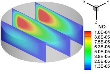
23 A more detailed analysis follows now, which is based on the numerical results of the CFD code. More specifically, from the simulations implemented the burned and unburned mass-weighted gas temperatures are calculated for all cases examined. As burned computational cells (for the computation of the burned gas temperature) are considered the ones, in which more than 90% of their initial fuel has been consumed. The results are shown in Fig. 16, where the high increase of the burned gas temperature for the stoichiometric mixtures for both compression ratios is evident. The maximum burned gas temperature for stoichiometric mixtures is around 2800 K, whereas for the leaner mixtures is below 2000 K. It should be mentioned that the elaborated temperatures are the mean temperatures of the burned and unburned gas, since for leaner mixtures there are some cells that contain burned gas with much higher temperature (especially near the spark-plug). An observation derived from Fig. 16 is the rapid increase of the unburned gas temperature just after the ignition timing, especially for the richer mixtures. This is due to the faster hydrogen combustion occurring in these cases, where the unburned mass is further compressed and heated due to the expansion of the burned gas [47]. Concerning the produced NO emissions, it can be seen that for the richer mixtures there is an immediate and rapid NO production just after the ignition timing (following the rapid increase of the burned temperature), and this is intensive only during the period when the mass-weighted burned temperature is increasing. On the contrary, for the leaner mixtures some NO production delay is observed, which is due to the existence of lower burned gas temperatures. Another interesting observation is that the NO production process is terminated when the mean burned gas temperature obtains values lower than 2000 K. This is true for the medium and high load cases, in contrast to the low load cases where this threshold is significantly reduced being equal to around 1700 K. Additionally, for the two leaner mixtures (φ=0.75 and φ=0.50) the maximum incylinder mean NO concentration is actually equal to the exhaust one as well [11]. However, this is not the case for the richer mixture (φ=1) where the maximum NO concentration is observed at the early stages of combustion (around 10 0 CA after IT), and the exhaust one is quite lower and freezes at almost 30 0 CA later [11,13], due to the dissociation of NO, when the burned temperature starts to decrease; but still, it is way over the temperature threshold of 2000 K. The dependence of NO emissions from the prevailing local temperatures can be observed with greater detail in Fig. 17, where the images show the in-cylinder spatial 21
24 distribution of temperature and NO mass fraction for the cases only with compression ratio equal to 8; similar results are also obtained when investigating the Cases 4-6 of Table 2 (higher compression ratio of 9). These images show the evolution of the spatial temperature field, together with the NO mass fraction distribution, for selected time instants and planes after the spark-timing for the three loads. One should notice the different contour range for the temperature and the NO mass fraction, as the equivalence ratio changes, while the upper right hand side plane is the one crossing the spark-plug. It can be observed with higher detail, how the NO production strictly follows the temperature variation. For the richer mixture case, during the late stages of combustion when the gas temperature decreases due to expansion, the NO production process has actually terminated, having a more homogeneous distribution inside the cylinder, in contrast to the early stages of combustion. Nevertheless, closer to the sparkplug the NO concentration is slightly higher than in the outer regions close to the cylinder liner. Additionally, for the leaner mixtures (φ=0.75 and φ=0.50) the higher NO concentration is observed also near to the spark-plug for the whole combustion period, where the prevailing temperatures also are higher, but a significant in-cylinder NO mass fraction stratification is introduced. From these images it is observed that for the richer mixture at 12 0 CA after the ignition-timing the NO mass fraction starts slightly to decrease, whereas for the medium load the NO emissions freeze at their maximum value at around 20 0 CA after the ignition-timing, with higher values near the spark-plug. For the low load case, even at 28 0 CA after the ignition-timing some NO emissions are still being produced. The NO production delay that was pointed out before for the leaner mixtures (Fig. 16), can be better identified here for all three loads, since this delay is observed for the rich mixture at the beginning of the combustion period (around 4 0 CA after IT), for the medium load at around 12 0 CA after IT, and for the lower load near the end of combustion at almost 20 0 CA after IT. 5. Summary and conclusions A combined experimental and numerical investigation has been carried out concerning a hydrogen-fueled spark-ignition engine at two compression ratios and three equivalence ratios at MBT timing and constant engine speed (600 rpm). The experimental procedure involved the measurement of the cylinder pressure traces, wall temperatures and heat fluxes at three locations at the cylinder liner, the inlet air and 22
25 hydrogen flow rates, and additionally the tailpipe exhaust NO emissions for all cases examined. The numerical results obtained from a validated in-house CFD code were compared with the available measurements, in order to validate the heat transfer mechanism, so that then these could be used to investigate, with more detail, some of the in-cylinder processes taking place. More specifically, the combustion efficiency of the spark-ignition engine was examined for all cases, showing that this efficiency holds high values of over 95%, which are further increased as the equivalence ratio is increased. The local wall heat fluxes and the cumulative heat loss were then provided for all cases examined here, giving some insight into the heat loss ratio, which is substantially decreased as the load and compression ratio decreases. Afterwards, performance figures were presented using the available data from both measurements and calculated results of the CFD code, with a final scope to calculate the indicated efficiency and its variation with the equivalence ratio and compression ratio. One important scope of the present study was to provide a better understanding of the emissions production mechanisms, and its dependence on the burned gas temperature/load. The spatial distribution of the NO emissions was also presented using the results of the CFD code, in association with the mean in-cylinder gas temperature at the same instants of time. The NO emissions production pattern was also described for every mixture, showing how this evolves during the combustion period, initiating from the ignition-timing moment until their concentration being actually frozen (a few degrees CA after IT). This in-depth investigation can be considered reliable, since the numerical results obtained have been further validated by comparing its values with available measured data. Additionally, the calculated data of the CFD code can provide with great detail a description of the in-cylinder phenomena, especially for the ones that are very difficult to measure or notice, such as the NO spatial production rate and the combustion efficiency incorporating the three inefficiency mechanisms described. Acknowledgements G.M. Kosmadakis wishes to thank the Greek State Scholarships Foundation for granting him a Ph.D. research scholarship. J. Demuynck likes to acknowledge Institute for the Promotion of Innovation through Science and Technology in Flanders (IWT-Vlaanderen) 23
26 for supporting him with a grant (SB-81139). The experimental equipment is funded by a Research Grant ( N) of the Research Foundation - Flanders (FWO). References [1] Verhelst S. A study of the combustion in hydrogen-fuelled internal combustion engines. Ph.D. Thesis, Ghent University, Ghent, Belgium, (URL: [2] Demuynck J, Raes N, Zuliani M, De Paepe M, Sierens R, Verhelst S. Local heat flux measurements in a hydrogen and methane spark ignition engine with a thermopile sensor. Int J Hydrogen Energy 2009;34(24): [3] Verhelst S, Sierens R. Combustion studies for PFI hydrogen IC engines. SAE Paper no ; [4] Verhelst S, De Landtsheere J, De Smet F, Billiouw C, Trenson A, Sierens R. Effects of supercharging, EGR and variable valve timing on power and emissions of hydrogen internal combustion engines. SAE Int J Engines 2009;1(1): [SAE Paper no ; 2008]. [5] Nande AM, Szwaja S, Naber JD. Impact of EGR on combustion processes in a hydrogen fuelled SI engine. SAE Paper no ; [6] Rottengruber H, Berckmueller M, Elsaesser G, Brehm N, Schwarz C. Direct-injection hydrogen SI-engine operation strategy and power density potentials. Trans SAE, J Fuels Lubricants 2004;113: [SAE Paper no ]. [7] Gerke U. Numerical analysis of mixture formation and combustion in a hydrogen directinjection internal combustion engine. Ph.D. Thesis, Diss. ETH No , Cuvillier Göttingen, ETH Zurich, Switzerland, (URL: [8] Shudo T. Improving thermal efficiency by reducing cooling losses in hydrogen combustion engines. Int J Hydrogen Energy 2007;32(17): [9] Mohammadi A, Shioji M, Nakai Y, Ishikura W, Tabo E. Performance and combustion characteristics of a direct-injection SI hydrogen engine. Int J Hydrogen Energy 2007;32(2): [10] Verhelst S, Sierens R. A quasi-dimensional model for the power cycle of a hydrogenfuelled ICE. Int J Hydrogen Energy 2007;32(15): [11] Safari H, Jazayeri SA, Ebrahimi R. Potentials of NO X emission reduction methods in SI hydrogen engines: Simulation study. Int J Hydrogen Energy 2009;34(2): [12] Dimopoulos P, Rechsteiner C, Soltic P, Laemmle C, Boulouchos K. Increase of passenger car engine efficiency with low engine-out emissions using hydrogen natural gas mixtures: A thermodynamic analysis. Int J Hydrogen Energy 2007;32(14):
27 [13] Knop V, Benkenida A, Jay S, Colin O. Modelling of combustion and nitrogen oxide formation in hydrogen-fuelled internal combustion engines within a 3D CFD code. Int J Hydrogen Energy 2008;33(19): [14] Sukumaran S, Kong S-C. Numerical study on mixture formation characteristics in a directinjection hydrogen engine. Int J Hydrogen Energy 2010;35(15): [15] Shudo T, Nabetani S. Analysis of degree of constant volume and cooling loss in a hydrogen fuelled SI engine. Trans SAE, J Fuels Lubricants 2001;110: [SAE Paper no ]. [16] Rakopoulos CD, Kosmadakis GM, Pariotis EG. Evaluation of a combustion model for the simulation of hydrogen spark-ignition engines using a CFD code. Int J Hydrogen Energy 2010;35(22): [17] Han Z, Reitz RD. Turbulence modeling of internal combustion engines using RNG k-ε models. Combust Sci Technol 1995;106(4): [18] Thakur S, Wright JR. A multiblock operator-splitting algorithm for unsteady flows at all speeds in complex geometries. Int J Numer Methods Fluids 2004;46(4): [19] Shyy W. Computational modeling for fluid flow and interfacial transport. Amsterdam: Elsevier Science; [20] Rakopoulos CD, Kosmadakis GM, Dimaratos AM, Pariotis EG. Investigating the effect of crevice flow on internal combustion engines using a new simple crevice model implemented in a CFD code. Appl Energy 2011;88(1): [21] Rakopoulos CD, Kosmadakis GM, Pariotis EG. Critical evaluation of current heat transfer models used in CFD in-cylinder engine simulations and establishment of a comprehensive wall-function formulation. Appl Energy 2010;87(5): [22] Rakopoulos CD, Kosmadakis GM, Pariotis EG. Evaluation of a new computational fluid dynamics model for internal combustion engines using hydrogen under motoring conditions. Energy 2009;34(12): [23] Launder BE, Spalding DB. The numerical computation of turbulent flows. Comput Methods Appl Mech Engrg 1974;3(2): [24] Han Z, Reitz RD. A temperature wall function formulation for variable-density turbulent flows with application to engine convective heat transfer modeling. Int J Heat Mass Transfer 1997;40(3): [25] Rakopoulos CD, Kosmadakis GM, Pariotis EG. Simulation of a motored internal combustion engine using an improved CFD code, In: Proc of the 23 rd International Conference on Efficiency, Cost, Optimization, Simulation and Environmental Impact of Energy Systems (ECOS 2010), June 14 17, 2010, Lausanne, Switzerland, Paper no [26] Verhelst S, Wallner T. Hydrogen-fueled internal combustion engines. Prog Energy Combust Sci 2009;35(6):
28 [27] Gerke U, Steurs K, Rebecchi P, Boulouchos K. Derivation of burning velocities of premixed hydrogen/air flames at engine-relevant conditions using a single-cylinder compression machine with optical access. Int J Hydrogen Energy 2010;35(6): [28] Zimont VL. Gas premixed combustion at high turbulence. Turbulent flame closure combustion model. Exp Therm Fluid Sci 2000;21(1-3): [29] Lipatnikov AN, Chomiak J. A simple model of unsteady turbulent flame propagation. Trans SAE, J Engines 1997;106: [SAE Paper no ]. [30] Abraham J, Bracco FV, Reitz RD. Comparison of computed and measured premixed charge engine combustion. Combust Flame 1985;60(3): [31] Fan L, Reitz RD. Development of an ignition and combustion model for spark-ignition engines. Trans SAE, J Engines 2000;109: [SAE Paper no ]. [32] Masood M, Ishrat MM, Reddy AS. Computational combustion and emission analysis of hydrogen-diesel blends with experimental verification. Int J Hydrogen Energy 2007;32(13): [33] Kong S-C, Ayoub N, Reitz RD. Modeling combustion in compression ignition homogeneous charge engines. Trans SAE, J Engines 1992;101: [SAE Paper no ]. [34] Lavoie GA, Heywood JB, Keck JC. Experimental and theoretical study of nitric oxide formation in internal combustion engines. Combust Sci Technol 1970;1(4): [35] Rakopoulos CD, Michos CN. Development and validation of a multi-zone combustion model for performance and nitric oxide formation in syngas fueled spark ignition engine. Energy Convers Manage 2008;49(10): [36] Fox JW, Cheng WK, Heywood JB. A model for predicting residual gas fraction in sparkignition engines. Trans SAE, J Engines 1993;102: [SAE Paper no ]. [37] Senecal PK, Xin J, Reitz RD. Predictions of residual gas fraction in IC engines. Trans SAE, J Engines 1996;105: [SAE Paper no ]. [38] Swain MR, Swain MN, Leisz A, Adt RR. Hydrogen peroxide emissions from a hydrogen fueled engine. Int J Hydrogen Energy 1990;15(4): [39] Sinclair LA, Wallace JS. Lean limit emissions of hydrogen-fueled engines. Int J Hydrogen Energy 1984;9(1-2): [40] Das LM. Exhaust emission characterization of hydrogen-operated engine system: Nature of pollutants and their control techniques. Int J Hydrogen Energy 1991;16(11): [41] Obermair H, Scarcelli R, Wallner T. Efficiency improved combustion systems for hydrogen direct injection operation. SAE Paper no ; [42] Rakopoulos CD, Mavropoulos GC. Experimental evaluation of local instantaneous heat transfer characteristics in the combustion chamber of air-cooled direct injection diesel engine. Energy 2008;33(7):
29 [43] Chang J, Güralp O, Filipi Z, Assanis D, Kuo T-W, Najt P, Rask R. New heat transfer correlation for an HCCI engine derived from measurements of instantaneous surface heat flux. SAE Paper no ; [44] Verhelst S, T Joen C, Vancoillie J, Demuynck J. A correlation for the laminar burning velocity for use in hydrogen spark ignition engine simulation. Int J Hydrogen Energy (2010), doi: /j.ijhydene [45] Rakopoulos CD, Antonopoulos KA, Rakopoulos DC. Experimental heat release analysis and emissions of a HSDI diesel engine fueled with ethanol-diesel fuel blends. Energy 2007;32(10): [46] Verhelst S, Sierens R, Verstraeten S. A critical review of experimental research on hydrogen fueled SI engines. Trans SAE, J Engines 2006;115: [SAE Paper no ]. [47] Rakopoulos CD, Michos CN, Giakoumis EG. Thermodynamic analysis of SI engine operation on variable composition biogas-hydrogen blends using a quasi-dimensional, multi-zone combustion model. SAE Int J Engines 2009;2(1): [SAE Paper no ]. Tables Captions Table 1 Table 2 Table 3 Table 4 CFR engine specifications. Test cases examined in the present study. Cumulative heat loss to the cylinder walls for all cases examined. Exhaust heat and gas temperatures for all cases examined. Table 1 CFR engine specifications. Engine model and type CFR engine, single cylinder, naturally aspirated, four-stroke, water-cooled 27
30 Bore mm Stroke mm Swept volume lit Connecting rod length 254 mm Compression ratio Variable (CR: 8 and 9) Valves 2 (unshrouded) Engine speed 600 rpm (constant) Ignition timing ΜΒΤ Number of piston rings 5 Valve Inlet valve opening 17 0 CA ATDC timing Inlet valve closure 26 0 CA ABDC events Exhaust valve opening 32 0 CA BBDC Exhaust valve closure 6 0 CA ATDC Table 2 Test cases examined in the present study. Equivalence Compression MBT timing Case ratio (φ) ratio (CR) in 0 CA ATDC Table 3 Cumulative heat loss to the cylinder walls for all cases examined. Case Calculated cumulative heat loss (J) Measured cumulative heat loss (J) (based on measured local heat fluxes) 28
31 Table 4 Exhaust heat and gas temperatures for all cases examined. Case Exhaust heat ratio n ex (%) Exhaust heat Q (J) ex Measured exhaust gas temperature (K) Figures Captions Fig. 1 Cross-section of the CFR engine, P1: spark plug, P2 P4: sensor positions, IV: intake valve, EV: exhaust valve. Fig. 2 Effect of equivalence ratio and compression ratio on the local wall temperature history at P3 location of the CFR engine (measured values). Fig. 3 Effect of equivalence ratio and compression ratio on the peak wall-heat flux at P2 location of the CFR engine (measured values). Fig. 4 Computational mesh at IVC for the CFR engine (CR=9). Fig. 5 Combustion efficiency and theoretical heat of combustion for all cases examined, for the CFR engine. Fig. 6 Contribution of the various mechanisms on the combustion inefficiency for all cases examined, for the CFR engine. Fig. 7 Comparison of calculated local wall heat fluxes with the measured data of the CFR engine, for compression ratio equal to 8. Fig. 8 Comparison of calculated local wall heat fluxes with the measured data of the CFR engine, for compression ratio equal to 9. Fig. 9 Mean calculated wall heat loss for all cases examined, for the CFR engine. Fig. 10 Heat loss ratio and real heat of combustion for all cases examined, for the CFR engine. 29
32 Fig. 11 Comparison of calculated cylinder pressure history with the measured one, for all cases examined of the CFR engine. Fig. 12 Comparison of calculated net heat release rate with the measured one, for all cases examined of the CFR engine. Fig. 13 Comparison of calculated gross indicated work with the measured one for all cases examined of the CFR engine. Fig. 14 Comparison of calculated indicated efficiency (gross) with the measured one for all cases examined of the CFR engine. Fig. 15 Comparison of calculated exhaust NO emissions with the measured ones for all cases examined of the CFR engine. Fig. 16 Mass-weighted burned and unburned gas temperatures and NO emissions, for all cases examined of the CFR engine. Fig. 17 NO mass fraction and temperature spatial distributions during the combustion period for compression ratio equal to 8 (Cases 1-3 of Table 2). Fig. 1 Rakopoulos et al. 30
33 Peak wall-heat flux at P2 (MW/m 2 ) Wall temperature at P3 ( o C) φ=1 φ=0.75 φ= CR=8 IT=MBT CR=9 IT=MBT Crank angle degrees (ABDC) Fig. 2 Rakopoulos et al. 5 4 CR=8 CR= Equivalence ratio Fig. 3 Rakopoulos et al. 31
34 Combustion efficiency (%) Theoretical heat of combustion (J) X Y Z Fig. 4 Rakopoulos et al CR: 8 CR: Equivalence ratio 800 Fig. 5 Rakopoulos et al. 32
35 Combustion inefficiency (%) Combustion inefficiency (%) 5 4 Unburned H 2 in the exhaust gas H 2 lost in blow-by gas Combustion dissociation 5 4 Unburned H 2 in the exhaust gas H 2 lost in blow-by gas Combustion dissociation 3 CR: 8 / IT: MBT n u =95.38% n u=95.78% n u=96.69% 3 CR: 9 / IT: MBT n u =95.03% n u =95.77% n u=96.54% Equivalence ratio Equivalence ratio Fig. 6 Rakopoulos et al. 33
36 Local wall-heat flux (MW/m 2 ) Local wall-heat flux (MW/m 2 ) φ=1 IT=6 0 CA ATDC φ=0.75 IT=2 0 CA ATDC P2 location - CR: 8 Measured Calculated φ=0.50 IT=4 0 CA BTDC φ=1 IT=6 0 CA ATDC Crank angle degrees (ABDC) φ=0.75 IT=2 0 CA ATDC P3 location - CR: 8 Measured Calculated φ=0.50 IT=4 0 CA BTDC Crank angle degrees (ABDC) Fig. 7 Rakopoulos et al. 34
37 Local wall-heat flux (MW/m 2 ) Local wall-heat flux (MW/m 2 ) φ=1 IT=14 0 CA ATDC φ=0.75 IT=8 0 CA ATDC P2 location - CR: 9 Measured Calculated φ=0.50 IT=TDC φ=1 IT=14 0 CA ATDC Crank angle degrees (ABDC) φ=0.75 IT=8 0 CA ATDC P3 location - CR: 9 Measured Calculated φ=0.50 IT=TDC Crank angle degrees (ABDC) Fig. 8 Rakopoulos et al. 35
38 Heat loss ratio (%) Real heat of combustion (J) Mean wall heat loss (W) φ=0.5 φ=0.75 φ= CR: 8 ΙΤ: ΜΒΤ Crank angle degrees (ABDC) CR: 9 ΙΤ: ΜΒΤ Fig. 9 Rakopoulos et al CR: 8 CR: Equivalence ratio 800 Fig. 10 Rakopoulos et al. 36
39 Cylinder pressure (bar) Cylinder pressure (bar) CR: 8 φ: 1 IT: 6 0 CA ATDC CR: 8 φ: 0.75 IT: 2 0 CA ATDC Measured Calculated CR: 8 φ: 0.50 IT: 4 0 CA BTDC CR: 9 φ: 1 IT: 14 0 CA ATDC Crank angle degrees (ABDC) CR: 9 φ: 0.75 IT: 8 0 CA ATDC CR: 9 φ: 0.50 IT: TDC Crank angle degrees (ABDC) Fig. 11 Rakopoulos et al. 37
40 Net heat release rate (J/ o CA) Net heat release rate (J/ o CA) CR: 8 φ: 1 IT: 6 0 CA ATDC CR: 9 φ: 1 IT: 14 0 CA ATDC CR: 8 φ: 0.75 IT: 2 0 CA ATDC Crank angle degrees (ABDC) CR: 9 φ: 0.75 IT: 8 0 CA ATDC Crank angle degrees (ABDC) Experimental Calculated CR: 8 φ: 0.50 IT: 4 0 CA BTDC CR: 9 φ: 0.50 IT: TDC Fig. 12 Rakopoulos et al. 38
41 Indicated efficiency (%) Indicated efficiency (%) Gross indicated work (J) Measured Calculated CR: 8 IT: MBT Equivalence ratio CR: 9 IT: MBT Fig. 13 Rakopoulos et al Measured Calculated CR: 8 CR: Equivalence ratio Equivalence ratio Fig. 14 Rakopoulos et al. 39
42 Exhaust NO emissions (ppm) Measured Calculated CR: 8 IT: MBT Equivalence ratio CR: 9 IT: MBT Fig. 15 Rakopoulos et al. 40
43 Mass-weighted temperatures (K) NO emissions (kg NO /kg mixture ) Mass-weighted temperatures (K) NO emissions (kg NO /kg mixture ) CR: 8 φ: 1 IT: 6 0 CA ATDC Burned gas temperature Unburned gas temperature NO emissions CR: 8 φ: 0.75 IT: 2 0 CA ATDC CR: 8 φ: 0.50 IT: 4 0 CA BTDC 1E-001 1E E E Crank angle degrees (ABDC) CR: 9 φ: 1 IT: 14 0 CA ATDC CR: 9 φ: 0.75 IT: 8 0 CA ATDC CR: 9 φ: 0.50 IT: TDC 1E-005 1E-001 1E E E Crank angle degrees (ABDC) E-005 Fig. 16 Rakopoulos et al. 41
44 0 CA after IT φ=1 φ=0.75 φ=

45 28 Fig. 17 Rakopoulos et al. 43
In: INTERNATIONAL JOURNAL OF HYDROGEN ENERGY, 37 (14), pp , 2012
, pp , 2012") biblio.ugent.be The UGent Institutional Repository is the electronic archiving and dissemination platform for all UGent research publications. Ghent University has implemented a mandate stipulating that
biblio.ugent.be The UGent Institutional Repository is the electronic archiving and dissemination platform for all UGent research publications. Ghent University has implemented a mandate stipulating that
Normal vs Abnormal Combustion in SI engine. SI Combustion. Turbulent Combustion
 Turbulent Combustion The motion of the charge in the engine cylinder is always turbulent, when it is reached by the flame front. The charge motion is usually composed by large vortexes, whose length scales
Natural Gas fuel for Internal Combustion Engine
 Natural Gas fuel for Internal Combustion Engine L. Bartolucci, S. Cordiner, V. Mulone, V. Rocco University of Rome Tor Vergata Department of Industrial Engineering Outline Introduction Motivations and
Marc ZELLAT, Driss ABOURI, Thierry CONTE and Riyad HECHAICHI CD-adapco
 16 th International Multidimensional Engine User s Meeting at the SAE Congress 2006,April,06,2006 Detroit, MI RECENT ADVANCES IN SI ENGINE MODELING: A NEW MODEL FOR SPARK AND KNOCK USING A DETAILED CHEMISTRY
ACTUAL CYCLE. Actual engine cycle
 1 ACTUAL CYCLE Actual engine cycle Introduction 2 Ideal Gas Cycle (Air Standard Cycle) Idealized processes Idealize working Fluid Fuel-Air Cycle Idealized Processes Accurate Working Fluid Model Actual
Marc ZELLAT, Driss ABOURI and Stefano DURANTI CD-adapco
 17 th International Multidimensional Engine User s Meeting at the SAE Congress 2007,April,15,2007 Detroit, MI RECENT ADVANCES IN DIESEL COMBUSTION MODELING: THE ECFM- CLEH COMBUSTION MODEL: A NEW CAPABILITY
Module 3: Influence of Engine Design and Operating Parameters on Emissions Lecture 14:Effect of SI Engine Design and Operating Variables on Emissions
 Module 3: Influence of Engine Design and Operating Parameters on Emissions Effect of SI Engine Design and Operating Variables on Emissions The Lecture Contains: SI Engine Variables and Emissions Compression
Foundations of Thermodynamics and Chemistry. 1 Introduction Preface Model-Building Simulation... 5 References...
 Contents Part I Foundations of Thermodynamics and Chemistry 1 Introduction... 3 1.1 Preface.... 3 1.2 Model-Building... 3 1.3 Simulation... 5 References..... 8 2 Reciprocating Engines... 9 2.1 Energy Conversion...
Comparison of Swirl, Turbulence Generating Devices in Compression ignition Engine
 Available online atwww.scholarsresearchlibrary.com Archives of Applied Science Research, 2016, 8 (7):31-40 (http://scholarsresearchlibrary.com/archive.html) ISSN 0975-508X CODEN (USA) AASRC9 Comparison
CHAPTER 1 INTRODUCTION
 1 CHAPTER 1 INTRODUCTION 1.1 GENERAL Diesel engines are the primary power source of vehicles used in heavy duty applications. The heavy duty engine includes buses, large trucks, and off-highway construction
EFFECT OF INJECTION ORIENTATION ON EXHAUST EMISSIONS IN A DI DIESEL ENGINE: THROUGH CFD SIMULATION
 EFFECT OF INJECTION ORIENTATION ON EXHAUST EMISSIONS IN A DI DIESEL ENGINE: THROUGH CFD SIMULATION *P. Manoj Kumar 1, V. Pandurangadu 2, V.V. Pratibha Bharathi 3 and V.V. Naga Deepthi 4 1 Department of
Homogeneous Charge Compression Ignition combustion and fuel composition
 Loughborough University Institutional Repository Homogeneous Charge Compression Ignition combustion and fuel composition This item was submitted to Loughborough University's Institutional Repository by
COMBUSTION in SI ENGINES
 Internal Combustion Engines ME422 COMBUSTION in SI ENGINES Prof.Dr. Cem Soruşbay Internal Combustion Engines Combustion in SI Engines Introduction Classification of the combustion process Normal combustion
System Simulation for Aftertreatment. LES for Engines
 System Simulation for Aftertreatment LES for Engines Christopher Rutland Engine Research Center University of Wisconsin-Madison Acknowledgements General Motors Research & Development Caterpillar, Inc.
Combustion. T Alrayyes
 Combustion T Alrayyes Fluid motion with combustion chamber Turbulence Swirl SQUISH AND TUMBLE Combustion in SI Engines Introduction The combustion in SI engines inside the engine can be divided into three
Recent enhancement to SI-ICE combustion models: Application to stratified combustion under large EGR rate and lean burn
 Recent enhancement to SI-ICE combustion models: Application to stratified combustion under large EGR rate and lean burn G. Desoutter, A. Desportes, J. Hira, D. Abouri, K.Oberhumer, M. Zellat* TOPICS Introduction
A Study of EGR Stratification in an Engine Cylinder
 A Study of EGR Stratification in an Engine Cylinder Bassem Ramadan Kettering University ABSTRACT One strategy to decrease the amount of oxides of nitrogen formed and emitted from certain combustion devices,
SI engine combustion
 SI engine combustion 1 SI engine combustion: How to burn things? Reactants Products Premixed Homogeneous reaction Not limited by transport process Fast/slow reactions compared with other time scale of
CHAPTER 8 EFFECTS OF COMBUSTION CHAMBER GEOMETRIES
 112 CHAPTER 8 EFFECTS OF COMBUSTION CHAMBER GEOMETRIES 8.1 INTRODUCTION Energy conservation and emissions have become of increasing concern over the past few decades. More stringent emission laws along
Module7:Advanced Combustion Systems and Alternative Powerplants Lecture 32:Stratified Charge Engines
 ADVANCED COMBUSTION SYSTEMS AND ALTERNATIVE POWERPLANTS The Lecture Contains: DIRECT INJECTION STRATIFIED CHARGE (DISC) ENGINES Historical Overview Potential Advantages of DISC Engines DISC Engine Combustion
COMPUTATIONAL FLOW MODEL OF WESTFALL'S 2900 MIXER TO BE USED BY CNRL FOR BITUMEN VISCOSITY CONTROL Report R0. By Kimbal A.
 COMPUTATIONAL FLOW MODEL OF WESTFALL'S 2900 MIXER TO BE USED BY CNRL FOR BITUMEN VISCOSITY CONTROL Report 412509-1R0 By Kimbal A. Hall, PE Submitted to: WESTFALL MANUFACTURING COMPANY May 2012 ALDEN RESEARCH
Flow Simulation of Diesel Engine for Prolate Combustion Chamber
 IJIRST National Conference on Recent Advancements in Mechanical Engineering (RAME 17) March 2017 Flow Simulation of Diesel Engine for Prolate Combustion Chamber R.Krishnakumar 1 P.Duraimurugan 2 M.Magudeswaran
COMPRESSIBLE FLOW ANALYSIS IN A CLUTCH PISTON CHAMBER
 COMPRESSIBLE FLOW ANALYSIS IN A CLUTCH PISTON CHAMBER Masaru SHIMADA*, Hideharu YAMAMOTO* * Hardware System Development Department, R&D Division JATCO Ltd 7-1, Imaizumi, Fuji City, Shizuoka, 417-8585 Japan
Università degli Studi di Roma Tor Vergata Modeling Combustion of Methane- Hydrogen Blends in Internal Combustion Engines (BONG-HY)
") Università degli Studi di Roma Tor Vergata Modeling Combustion of Methane- Hydrogen Blends in Internal Combustion Engines (BONG-HY) Prof. Stefano Cordiner Ing. Vincenzo Mulone Ing. Riccardo Scarcelli Index
Università degli Studi di Roma Tor Vergata Modeling Combustion of Methane- Hydrogen Blends in Internal Combustion Engines (BONG-HY) Prof. Stefano Cordiner Ing. Vincenzo Mulone Ing. Riccardo Scarcelli Index
Engine Cycles. T Alrayyes
 Engine Cycles T Alrayyes Introduction The cycle experienced in the cylinder of an internal combustion engine is very complex. The cycle in SI and diesel engine were discussed in detail in the previous
COMBUSTION in SI ENGINES
 Internal Combustion Engines MAK 493E COMBUSTION in SI ENGINES Prof.Dr. Cem Soruşbay Istanbul Technical University Internal Combustion Engines MAK 493E Combustion in SI Engines Introduction Classification
Dual Fuel Engine Charge Motion & Combustion Study
 Dual Fuel Engine Charge Motion & Combustion Study STAR-Global-Conference March 06-08, 2017 Berlin Kamlesh Ghael, Prof. Dr. Sebastian Kaiser (IVG-RF), M. Sc. Felix Rosenthal (IFKM-KIT) Introduction: Operation
MODELING AND ANALYSIS OF DIESEL ENGINE WITH ADDITION OF HYDROGEN-HYDROGEN-OXYGEN GAS
 S465 MODELING AND ANALYSIS OF DIESEL ENGINE WITH ADDITION OF HYDROGEN-HYDROGEN-OXYGEN GAS by Karu RAGUPATHY* Department of Automobile Engineering, Dr. Mahalingam College of Engineering and Technology,
POTENTIAL OF A SUPERCHARGED PORT FUEL INJECTED HYDROGEN ENGINE
 EUROPE IN THE SECOND CENTURY OF AUTO-MOBILITY POTENTIAL OF A SUPERCHARGED PORT FUEL INJECTED HYDROGEN ENGINE Prof. dr. ir. Sebastian Verhelst, Prof. dr. ir. Roger Sierens Ghent University, Belgium ABSTRACT
AN EXPERIMENT STUDY OF HOMOGENEOUS CHARGE COMPRESSION IGNITION COMBUSTION AND EMISSION IN A GASOLINE ENGINE
 THERMAL SCIENCE: Year 2014, Vol. 18, No. 1, pp. 295-306 295 AN EXPERIMENT STUDY OF HOMOGENEOUS CHARGE COMPRESSION IGNITION COMBUSTION AND EMISSION IN A GASOLINE ENGINE by Jianyong ZHANG *, Zhongzhao LI,
Recent Advances in DI-Diesel Combustion Modeling in AVL FIRE A Validation Study
 International Multidimensional Engine Modeling User s Group Meeting at the SAE Congress April 15, 2007 Detroit, MI Recent Advances in DI-Diesel Combustion Modeling in AVL FIRE A Validation Study R. Tatschl,
Electromagnetic Fully Flexible Valve Actuator
 Electromagnetic Fully Flexible Valve Actuator A traditional cam drive train, shown in Figure 1, acts on the valve stems to open and close the valves. As the crankshaft drives the camshaft through gears
Emissions predictions for Diesel engines based on chemistry tabulation
 Emissions predictions for Diesel engines based on chemistry tabulation C. Meijer, F.A. Tap AVL Dacolt BV (The Netherlands) M. Tvrdojevic, P. Priesching AVL List GmbH (Austria) 1. Introduction It is generally
3D CFD Modeling of Gas Exchange Processes in a Small HCCI Free Piston Engine
 3D CFD Modeling of Gas Exchange Processes in a Small HCCI Free Piston Engine Aimilios Sofianopoulos, Benjamin Lawler, Sotirios Mamalis Department of Mechanical Engineering Stony Brook University Email:
R&D on Environment-Friendly, Electronically Controlled Diesel Engine
 20000 M4.2.2 R&D on Environment-Friendly, Electronically Controlled Diesel Engine (Electronically Controlled Diesel Engine Group) Nobuyasu Matsudaira, Koji Imoto, Hiroshi Morimoto, Akira Numata, Toshimitsu
Analysis of Parametric Studies on the Impact of Piston Velocity Profile On the Performance of a Single Cylinder Diesel Engine
 IOSR Journal of Mechanical and Civil Engineering (IOSR-JMCE) e-issn: 2278-1684,p-ISSN: 2320-334X, Volume 12, Issue 2 Ver. II (Mar - Apr. 2015), PP 81-85 www.iosrjournals.org Analysis of Parametric Studies
THE USE OF Φ-T MAPS FOR SOOT PREDICTION IN ENGINE MODELING
 THE USE OF ΦT MAPS FOR SOOT PREDICTION IN ENGINE MODELING Arturo de Risi, Teresa Donateo, Domenico Laforgia Università di Lecce Dipartimento di Ingegneria dell Innovazione, 731 via Arnesano, Lecce Italy
Internal Combustion Optical Sensor (ICOS)
") Internal Combustion Optical Sensor (ICOS) Optical Engine Indication The ICOS System In-Cylinder Optical Indication 4air/fuel ratio 4exhaust gas concentration and EGR 4gas temperature 4analysis of highly
Internal Combustion Optical Sensor (ICOS) Optical Engine Indication The ICOS System In-Cylinder Optical Indication 4air/fuel ratio 4exhaust gas concentration and EGR 4gas temperature 4analysis of highly
TECHNICAL PAPER FOR STUDENTS AND YOUNG ENGINEERS - FISITA WORLD AUTOMOTIVE CONGRESS, BARCELONA
 TECHNICAL PAPER FOR STUDENTS AND YOUNG ENGINEERS - FISITA WORLD AUTOMOTIVE CONGRESS, BARCELONA 2 - TITLE: Topic: INVESTIGATION OF THE EFFECTS OF HYDROGEN ADDITION ON PERFORMANCE AND EXHAUST EMISSIONS OF
Effects of Dilution Flow Balance and Double-wall Liner on NOx Emission in Aircraft Gas Turbine Engine Combustors
 Effects of Dilution Flow Balance and Double-wall Liner on NOx Emission in Aircraft Gas Turbine Engine Combustors 9 HIDEKI MORIAI *1 Environmental regulations on aircraft, including NOx emissions, have
NUMERICAL INVESTIGATION OF EFFECT OF EXHAUST GAS RECIRCULATION ON COMPRESSIONIGNITION ENGINE EMISSIONS
 ISSN (Online) : 2319-8753 ISSN (Print) : 2347-6710 International Journal of Innovative Research in Science, Engineering and Technology An ISO 3297: 2007 Certified Organization, Volume 2, Special Issue
2.61 Internal Combustion Engines Spring 2008
 MIT OpenCourseWare http://ocw.mit.edu 2.61 Internal Combustion Engines Spring 2008 For information about citing these materials or our Terms of Use, visit: http://ocw.mit.edu/terms. Engine Heat Transfer
Module 2:Genesis and Mechanism of Formation of Engine Emissions Lecture 3: Introduction to Pollutant Formation POLLUTANT FORMATION
 Module 2:Genesis and Mechanism of Formation of Engine Emissions POLLUTANT FORMATION The Lecture Contains: Engine Emissions Typical Exhaust Emission Concentrations Emission Formation in SI Engines Emission
SUCCESSFUL DIESEL COLD START THROUGH PROPER PILOT INJECTION PARAMETERS SELECTION. Aleksey Marchuk, Georgiy Kuharenok, Aleksandr Petruchenko
 SUCCESSFUL DIESEL COLD START THROUGH PROPER PILOT INJECTION PARAMETERS SELECTION Aleksey Marchuk, Georgiy Kuharenok, Aleksandr Petruchenko Robert Bosch Company, Germany Belarussian National Technical Universitry,
NUMERICAL INVESTIGATION OF PISTON COOLING USING SINGLE CIRCULAR OIL JET IMPINGEMENT
 NUMERICAL INVESTIGATION OF PISTON COOLING USING SINGLE CIRCULAR OIL JET IMPINGEMENT BALAKRISHNAN RAJU, CFD ANALYSIS ENGINEER, TATA CONSULTANCY SERVICES LTD., BANGALORE ABSTRACT Thermal loading of piston
Development of a two-dimensional internal combustion engines model using CFD for education purpose
 20th International Congress on Modelling and Simulation, Adelaide, Australia, 1 6 December 2013 www.mssanz.org.au/modsim2013 Development of a two-dimensional internal combustion engines model using CFD
Designing Efficient Engines: Strategies Based on Thermodynamics
 Designing Efficient Engines: Strategies Based on Thermodynamics Jerald A. Caton Texas A&M University College Station, TX for CRC Advanced Fuel & Engine Workshop Hyatt Regency Baltimore Inner Harbor Baltimore,
Heat Transfer Enhancement for Double Pipe Heat Exchanger Using Twisted Wire Brush Inserts
 Heat Transfer Enhancement for Double Pipe Heat Exchanger Using Twisted Wire Brush Inserts Deepali Gaikwad 1, Kundlik Mali 2 Assistant Professor, Department of Mechanical Engineering, Sinhgad College of
Effect of Reformer Gas on HCCI Combustion- Part II: Low Octane Fuels
 Effect of Reformer Gas on HCCI Combustion- Part II: Low Octane Fuels Vahid Hosseini, and M David Checkel Mechanical Engineering University of Alberta, Edmonton, Canada project supported by Auto21 National
REDUCTION OF EMISSIONS BY ENHANCING AIR SWIRL IN A DIESEL ENGINE WITH GROOVED CYLINDER HEAD
 REDUCTION OF EMISSIONS BY ENHANCING AIR SWIRL IN A DIESEL ENGINE WITH GROOVED CYLINDER HEAD Dr.S.L.V. Prasad 1, Prof.V.Pandurangadu 2, Dr.P.Manoj Kumar 3, Dr G. Naga Malleshwara Rao 4 Dept.of Mechanical
EEN-E2002 Combustion Technology 2017 LE 3 answers
 EEN-E2002 Combustion Technology 2017 LE 3 answers 1. Plot the following graphs from LEO-1 engine with data (Excel_sheet_data) attached on my courses? (12 p.) a. Draw cyclic pressure curve. Also non-fired
INFLUENCE OF INTAKE AIR TEMPERATURE AND EXHAUST GAS RECIRCULATION ON HCCI COMBUSTION PROCESS USING BIOETHANOL
 ENGINEERING FOR RURAL DEVELOPMENT Jelgava, 2.-27..216. INFLUENCE OF INTAKE AIR TEMPERATURE AND EXHAUST GAS RECIRCULATION ON HCCI COMBUSTION PROCESS USING BIOETHANOL Kastytis Laurinaitis, Stasys Slavinskas
Numerically Analysing the Effect of EGR on Emissions of DI Diesel Engine Having Toroidal Combustion Chamber Geometry
 Numerically Analysing the Effect of EGR on Emissions of DI Diesel Engine Having Toroidal Combustion Chamber Geometry Jibin Alex 1, Biju Cherian Abraham 2 1 Student, Dept. of Mechanical Engineering, M A
INFLUENCE OF THE NUMBER OF NOZZLE HOLES ON THE UNBURNED FUEL IN DIESEL ENGINE
 INFLUENCE OF THE NUMBER OF NOZZLE HOLES ON THE UNBURNED FUEL IN DIESEL ENGINE 1. UNIVERSITY OF RUSE, 8, STUDENTSKA STR., 7017 RUSE, BULGARIA 1. Simeon ILIEV ABSTRACT: The objective of this paper is to
Thermo-Kinetic Model to Predict Start of Combustion in Homogeneous Charge Compression Ignition Engine
 Thermo-Kinetic Model to Predict Start of Combustion in Homogeneous Charge Compression Ignition Engine Harshit Gupta and J. M. Malliarjuna Abstract Now-a-days homogeneous charge compression ignition combustion
Figure 1: The spray of a direct-injecting four-stroke diesel engine
 MIXTURE FORMATION AND COMBUSTION IN CI AND SI ENGINES 7.0 Mixture Formation in Diesel Engines Diesel engines can be operated both in the two-stroke and four-stroke process. Diesel engines that run at high
The Effect of Volume Ratio of Ethanol Directly Injected in a Gasoline Port Injection Spark Ignition Engine
 10 th ASPACC July 19 22, 2015 Beijing, China The Effect of Volume Ratio of Ethanol Directly Injected in a Gasoline Port Injection Spark Ignition Engine Yuhan Huang a,b, Guang Hong a, Ronghua Huang b. a
Numerical Study on the Flow Characteristics of a Solenoid Valve for Industrial Applications
 Numerical Study on the Flow Characteristics of a Solenoid Valve for Industrial Applications TAEWOO KIM 1, SULMIN YANG 2, SANGMO KANG 3 1,2,4 Mechanical Engineering Dong-A University 840 Hadan 2 Dong, Saha-Gu,
Effect of Helix Parameter Modification on Flow Characteristics of CIDI Diesel Engine Helical Intake Port
 Effect of Helix Parameter Modification on Flow Characteristics of CIDI Diesel Engine Helical Intake Port Kunjan Sanadhya, N. P. Gokhale, B.S. Deshmukh, M.N. Kumar, D.B. Hulwan Kirloskar Oil Engines Ltd.,
Simulation of Performance Parameters of Spark Ignition Engine for Various Ignition Timings
 Research Article International Journal of Current Engineering and Technology ISSN 2277-4106 2013 INPRESSCO. All Rights Reserved. Available at http://inpressco.com/category/ijcet Simulation of Performance
Study of Performance and Emission Characteristics of a Two Stroke Si Engine Operated with Gasoline Manifold Injectionand Carburetion
 Indian Journal of Science and Technology, Vol 9(37), DOI: 10.17485/ijst/2016/v9i37/101984, October 2016 ISSN (Print) : 0974-6846 ISSN (Online) : 0974-5645 Study of Performance and Emission Characteristics
Multi Body Dynamic Analysis of Slider Crank Mechanism to Study the effect of Cylinder Offset
 Multi Body Dynamic Analysis of Slider Crank Mechanism to Study the effect of Cylinder Offset Vikas Kumar Agarwal Deputy Manager Mahindra Two Wheelers Ltd. MIDC Chinchwad Pune 411019 India Abbreviations:
Title. Author(s)Shudo, Toshio; Nabetani, Shigeki; Nakajima, Yasuo. CitationJSAE Review, 22(2): Issue Date Doc URL.
Shudo, Toshio; Nabetani, Shigeki; Nakajima, Yasuo. CitationJSAE Review, 22(2): Issue Date Doc URL.") Title Influence of specific heats on indicator diagram ana Author(s)Shudo, Toshio; Nabetani, Shigeki; Nakajima, Yasuo CitationJSAE Review, 22(2): 224-226 Issue Date 21-4 Doc URL http://hdl.handle.net/2115/32326
Title Influence of specific heats on indicator diagram ana Author(s)Shudo, Toshio; Nabetani, Shigeki; Nakajima, Yasuo CitationJSAE Review, 22(2): 224-226 Issue Date 21-4 Doc URL http://hdl.handle.net/2115/32326
Scholars' Mine. Hassan A. Khairallah. Summer 2015
 Scholars' Mine Doctoral Dissertations Student Research & Creative Works Summer 2015 Combustion and pollutant characteristics of IC engines fueled with hydrogen and diesel/hydrogen mixtures using 3D computations
STATE OF THE ART OF PLASMATRON FUEL REFORMERS FOR HOMOGENEOUS CHARGE COMPRESSION IGNITION ENGINES
 Bulletin of the Transilvania University of Braşov Vol. 3 (52) - 2010 Series I: Engineering Sciences STATE OF THE ART OF PLASMATRON FUEL REFORMERS FOR HOMOGENEOUS CHARGE COMPRESSION IGNITION ENGINES R.
CFD ANALYSIS ON LOUVERED FIN
 CFD ANALYSIS ON LOUVERED FIN P.Prasad 1, L.S.V Prasad 2 1Student, M. Tech Thermal Engineering, Andhra University, Visakhapatnam, India 2Professor, Dept. of Mechanical Engineering, Andhra University, Visakhapatnam,
* Corresponding author
 Characterization of Dual-Fuel PCCI Combustion in a Light-Duty Engine S. L. Kokjohn * and R. D. Reitz Department of Mechanical Engineering University of Wisconsin - Madison Madison, WI 5376 USA Abstract.
Performance and Emissions of the 1999 LS1 Engine. Edward Froehlich Eric Tribbett Lex Bayer Mechanical Engineering Department Stanford University
 Performance and Emissions of the 1999 LS1 Engine Edward Froehlich Eric Tribbett Lex Bayer Mechanical Engineering Department Stanford University 2 ABSTRACT In this study we examine the performance and emissions
International Journal of Scientific & Engineering Research, Volume 5, Issue 7, July-2014 ISSN
 ISSN 9-5518 970 College of Engineering Trivandrum Department of Mechanical Engineering arundanam@gmail.com, arjunjk91@gmail.com Abstract This paper investigates the performance of a shock tube with air
The influence of thermal regime on gasoline direct injection engine performance and emissions
 IOP Conference Series: Materials Science and Engineering PAPER OPEN ACCESS The influence of thermal regime on gasoline direct injection engine performance and emissions To cite this article: C I Leahu
2.61 Internal Combustion Engine Final Examination. Open book. Note that Problems 1 &2 carry 20 points each; Problems 3 &4 carry 10 points each.
 2.61 Internal Combustion Engine Final Examination Open book. Note that Problems 1 &2 carry 20 points each; Problems 3 &4 carry 10 points each. Problem 1 (20 points) Ethanol has been introduced as the bio-fuel
Potential of Large Output Power, High Thermal Efficiency, Near-zero NOx Emission, Supercharged, Lean-burn, Hydrogen-fuelled, Direct Injection Engines
 Available online at www.sciencedirect.com Energy Procedia 29 (2012 ) 455 462 World Hydrogen Energy Conference 2012 Potential of Large Output Power, High Thermal Efficiency, Near-zero NOx Emission, Supercharged,
Effect of Tangential Grooves on Piston Crown Of D.I. Diesel Engine with Retarded Injection Timing
 International Journal of Engineering Research and Development e-issn: 2278-067X, p-issn : 2278-800X, www.ijerd.com Volume 5, Issue 10 (January 2013), PP. 01-06 Effect of Tangential Grooves on Piston Crown
CONTROLLING COMBUSTION IN HCCI DIESEL ENGINES
 CONTROLLING COMBUSTION IN HCCI DIESEL ENGINES Nicolae Ispas *, Mircea Năstăsoiu, Mihai Dogariu Transilvania University of Brasov KEYWORDS HCCI, Diesel Engine, controlling, air-fuel mixing combustion ABSTRACT
Rapid Meshing and Advanced Physical Modeling for Gasoline DI Engine Application
 Rapid Meshing and Advanced Physical Modeling for Gasoline DI Engine Application R. Tatschl, H. Riediger, Ch. v. Künsberg Sarre, N. Putz and F. Kickinger AVL LIST GmbH A-8020 Graz AUSTRIA Gasoline direct
Study of Performance and Environmental Emissions of a Gasoline Spark Ignition Engine
 ENERGY ENVIRONMENT International Journal of Sustainable Future for Human Security J-SustaiN Vol., No. (03 8 4 http://www.j-sustain.com Study of Performance and Environmental Emissions of a Gasoline Spark
Comparative performance and emissions study of a lean mixed DTS-i spark ignition engine operated on single spark and dual spark
 26 IJEDR Volume 4, Issue 2 ISSN: 232-9939 Comparative performance and emissions study of a lean mixed DTS-i spark ignition engine operated on single spark and dual spark Hardik Bambhania, 2 Vijay Pithiya,
Effect of Stator Shape on the Performance of Torque Converter
 16 th International Conference on AEROSPACE SCIENCES & AVIATION TECHNOLOGY, ASAT - 16 May 26-28, 2015, E-Mail: asat@mtc.edu.eg Military Technical College, Kobry Elkobbah, Cairo, Egypt Tel : +(202) 24025292
Control of PCCI Combustion using Physical and Chemical Characteristics of Mixed Fuel
 Doshisha Univ. - Energy Conversion Research Center International Seminar on Recent Trend of Fuel Research for Next-Generation Clean Engines December 5th, 27 Control of PCCI Combustion using Physical and
Abstract 1. INTRODUCTION
 Abstract Study on Performance Characteristics of Scuderi Split Cycle Engine Sudeer Gowd Patil 1, Martin A.J. 2, Ananthesha 3 1- M.Sc. [Engg.] Student, 2-Asst. Professor, 3-Asst.Professor, Department of
EFFECTS OF INTAKE AIR TEMPERATURE ON HOMOGENOUS CHARGE COMPRESSION IGNITION COMBUSTION AND EMISSIONS WITH GASOLINE AND n-heptane
 THERMAL SCIENCE: Year 2015, Vol. 19, No. 6, pp. 1897-1906 1897 EFFECTS OF INTAKE AIR TEMPERATURE ON HOMOGENOUS CHARGE COMPRESSION IGNITION COMBUSTION AND EMISSIONS WITH GASOLINE AND n-heptane by Jianyong
HERCULES-2 Project. Deliverable: D8.8
 HERCULES-2 Project Fuel Flexible, Near Zero Emissions, Adaptive Performance Marine Engine Deliverable: D8.8 Study an alternative urea decomposition and mixer / SCR configuration and / or study in extended
Influence of ANSYS FLUENT on Gas Engine Modeling
 Influence of ANSYS FLUENT on Gas Engine Modeling George Martinas, Ovidiu Sorin Cupsa 1, Nicolae Buzbuchi, Andreea Arsenie 2 1 CERONAV 2 Constanta Maritime University Romania georgemartinas@ceronav.ro,
Thermal Stress Analysis of Diesel Engine Piston
 International Conference on Challenges and Opportunities in Mechanical Engineering, Industrial Engineering and Management Studies 576 Thermal Stress Analysis of Diesel Engine Piston B.R. Ramesh and Kishan
MODELING THE COMBUSTION OF (M)ETHANOL IN SPARK-IGNITION ENGINES
ETHANOL IN SPARK-IGNITION ENGINES") F2014-CET-095 MODELING THE COMBUSTION OF (M)ETHANOL IN SPARK-IGNITION ENGINES 1 Vancoillie, Jeroen; 1 Sileghem, Louis; 1 Verhelst, Sebastian* 1 Dept. Flow, Heat and Combustion Mechanics, Ghent University,
F2014-CET-095 MODELING THE COMBUSTION OF (M)ETHANOL IN SPARK-IGNITION ENGINES 1 Vancoillie, Jeroen; 1 Sileghem, Louis; 1 Verhelst, Sebastian* 1 Dept. Flow, Heat and Combustion Mechanics, Ghent University,
1. INTRODUCTION 2. EXPERIMENTAL INVESTIGATIONS
 HIGH PRESSURE HYDROGEN INJECTION SYSTEM FOR A LARGE BORE 4 STROKE DIESEL ENGINE: INVESTIGATION OF THE MIXTURE FORMATION WITH LASER-OPTICAL MEASUREMENT TECHNIQUES AND NUMERICAL SIMULATIONS Dipl.-Ing. F.
Experimental Investigation of Performance and Emissions of a Stratified Charge CNG Direct Injection Engine with Turbocharger
 MATEC Web of Conferences 1, 7 (17 ) DOI:1.11/matecconf/1717 ICTTE 17 Experimental Investigation of Performance and Emissions of a Stratified Charge CNG Direct Injection Engine with charger Hilmi Amiruddin
INVESTIGATION ON EFFECT OF EQUIVALENCE RATIO AND ENGINE SPEED ON HOMOGENEOUS CHARGE COMPRESSION IGNITION COMBUSTION USING CHEMISTRY BASED CFD CODE
 Ghafouri, J., et al.: Investigation on Effect of Equivalence Ratio and Engine Speed on... THERMAL SCIENCE: Year 2014, Vol. 18, No. 1, pp. 89-96 89 INVESTIGATION ON EFFECT OF EQUIVALENCE RATIO AND ENGINE
Module 2:Genesis and Mechanism of Formation of Engine Emissions Lecture 9:Mechanisms of HC Formation in SI Engines... contd.
 Mechanisms of HC Formation in SI Engines... contd. The Lecture Contains: HC from Lubricating Oil Film Combustion Chamber Deposits HC Mixture Quality and In-Cylinder Liquid Fuel HC from Misfired Combustion
SECOND LAW ANALYSIS OF PREMIXED COMPRESSION IGNITION COMBUSTION IN A DIESEL ENGINE USING A THERMODYNAMIC ENGINE CYCLE SIMULATION.
 SECOND LAW ANALYSIS OF PREMIXED COMPRESSION IGNITION COMBUSTION IN A DIESEL ENGINE USING A THERMODYNAMIC ENGINE CYCLE SIMULATION A Thesis by SUSHIL S. OAK Submitted to the Office of Graduate Studies of
GT-POWER/SIMULINK SIMULATION AS A TOOL TO IMPROVE INDIVIDUAL CYLINDER AFR CONTROL IN A MULTICYLINDER S.I. ENGINE
 1 GT-Suite Users International Conference Frankfurt a.m., October 30 th 2000 GT-POWER/SIMULINK SIMULATION AS A TOOL TO IMPROVE INDIVIDUAL CYLINDER CONTROL IN A MULTICYLINDER S.I. ENGINE F. MILLO, G. DE
Combustion calibration in a Methane port fuel injection engine with the STAR-CD ISSIM embedding the ECFM-3Z model
 Prague Czech Republic March 7-9, 2016 Combustion calibration in a Methane port fuel injection engine with the STAR-CD ISSIM embedding the ECFM-3Z model INDEX 1. PROBLEM PROPOSED 2. ANALYTICAL & NUMERICAL
Numerical Investigation of the Effect of Excess Air and Thermal Power Variation in a Liquid Fuelled Boiler
 Proceedings of the World Congress on Momentum, Heat and Mass Transfer (MHMT 16) Prague, Czech Republic April 4 5, 2016 Paper No. CSP 105 DOI: 10.11159/csp16.105 Numerical Investigation of the Effect of
Turbostroje 2015 Návrh spojení vysokotlaké a nízkotlaké turbíny. Turbomachinery 2015, Design of HP and LP turbine connection
 Turbostroje 2015 Turbostroje 2015 Návrh spojení vysokotlaké a nízkotlaké turbíny Turbomachinery 2015, Design of HP and LP turbine connection J. Hrabovský 1, J. Klíma 2, V. Prokop 3, M. Komárek 4 Abstract:
Chapter 4 ANALYTICAL WORK: COMBUSTION MODELING
 a 4.3.4 Effect of various parameters on combustion in IC engines: Compression ratio: A higher compression ratio increases the pressure and temperature of the working mixture which reduce the initial preparation
Gas exchange and fuel-air mixing simulations in a turbocharged gasoline engine with high compression ratio and VVA system
 Third Two-Day Meeting on Internal Combustion Engine Simulations Using the OpenFOAM technology, Milan 22 nd -23 rd February 2018. Gas exchange and fuel-air mixing simulations in a turbocharged gasoline
MULTIPOINT SPARK IGNITION ENGINE OPERATING ON LEAN MIXTURE
 MULTIPOINT SPARK IGNITION ENGINE OPERATING ON LEAN MIXTURE Karol Cupiał, Arkadiusz Kociszewski, Arkadiusz Jamrozik Technical University of Częstochowa, Poland INTRODUCTION Experiment on multipoint spark
University Turbine Systems Research Industrial Fellowship. Southwest Research Institute
 Correlating Induced Flashback with Air- Fuel Mixing Profiles for SoLoNOx Biomass Injector Ryan Ehlig University of California, Irvine Mentor: Raj Patel Supervisor: Ram Srinivasan Department Manager: Andy
Simple Finite Heat Release Model (SI Engine)
") Simple Finite Heat Release Model (SI Engine) Introduction In the following, a finite burn duration is taken into account, in which combustion occurs at θ soc (Start Of Combustion), and continues until
Simple Finite Heat Release Model (SI Engine) Introduction In the following, a finite burn duration is taken into account, in which combustion occurs at θ soc (Start Of Combustion), and continues until
NEW CONCEPT OF A ROCKER ENGINE KINEMATIC ANALYSIS
 Journal of KONES Powertrain and Transport, Vol. 19, No. 3 2012 NEW CONCEPT OF A ROCKER ENGINE KINEMATIC ANALYSIS Miros aw Szymkowiak Kochanowskiego Street 13, 64-100 Leszno, Poland e-mail: szymkowiak@op.pl