A PROJECT REPORT ON DESIGN AND FABRICATION TWO STROKE PETROL ENGINE TEST RIG
|
|
|
- Ann Patience Marsh
- 5 years ago
- Views:
Transcription
1 A PROJECT REPORT ON DESIGN AND FABRICATION TWO STROKE PETROL ENGINE TEST RIG PREPARED BY STUDENTS OF FINAL YEAR DIPLOMA IN MECHANICAL ENGINEERING UNIVERSITY POLYTECHNIC ALIGARH MUSLIM UNIVERSITY ALIGARH UTTAR PRADESH 1
2 CONTENTS Contents Declaration by the candidate Certificate Acknowledgements Abstract List of figures List of table s i-ii iii iv v vi vii viii Chapters Pages 1. FUNDAMENTALS OF ENGINE Engine Heat Engine Types of Heat Engine External Combustion Engine Internal Combustion Engine Basic Engine Components Engine Components Nomenclature of Engine Working Principle of Engine Four-Stroke Spark Ignition Engine Four-Stroke Compression Engine Comparison of SI and CI Engine Two-Stroke Engine Comparison of Two-Stroke and Four-Stroke Engine CLASSIFICATION OF ENGINE Classification of IC Engines Cycle of Operation Types of Fuel Used Method of Charging Type of Ignition Type of Cooling Cylinder Arrangement 17 2
3 2.2 Applications of IC Engines Two-Stroke Engines Four-Stroke Engines ENGINE PERFORMANACE PARAMETERS Indicated Thermal Efficiency Break Thermal Efficiency Mechanical Efficiency Volumetric Efficiency Relative Efficiency Mean Effective Pressure Mean Piston Speed Specific Power Output Specific Fuel Consumption Air-Fuel Ratio Calorific Value TWO-STROKE SPARK IGNITION ENGINE TEST RIG INTRODUCTION Frame Materials Used and Their Specifications Mountings Prony Brake Dynamometer Shaft Coupling Fuel Bottle Engine CONCLUSIONS 28 BIBLIOGRAPHY 29 APPENDICES Appendix-Photographs of Two-Stroke Petrol Engine Test Rig A-1 Side View of Test Rig A-2 Side View of Test Rig A-3 Front View of Test Rig 3
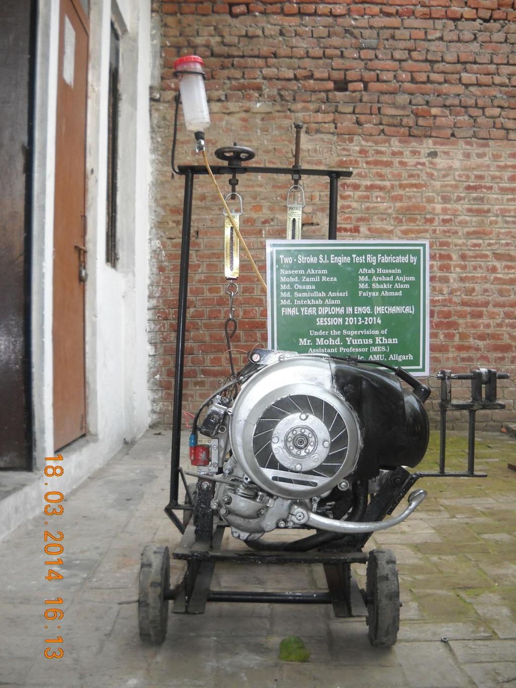
4 DECLARATION BY THE CANDIDATEs We the students of final year Diploma in Engineering (Mechanical Engineering), University Polytechnic, Aligarh Muslim University), Aligarh hereby declare that we are fully responsible for the information, result and conclusions etc. provided in this project DESIGN AND FABRICATION OF TWO-STROKE PETROL ENGINE TEST RIG submitted to Aligarh Muslim University, Aligarh for the of Diploma in Engineering (Mechanical Engineering). We have completely taken care acknowledging the contributions of others in this academic work. We further declare that in case of any violation of intellectual property rights or copyrights found at any stage, we will be responsible for that. MOHAMMAD ZAMIL REZA NASEEM AKRAM (11-DPIM 204) (11-DPIM 234) MD OSAMA MD ARSHAD ANJUM (11-DPIM 216) (11-DPIM 214) MD SHAKIR ALAM FAIYAZ AHMAD (11-DPIM 198) (11-DPIM 188) MD INTEKHAB ALAM AFTAB HUSSAIN (11-DPIM 199) (11-DPIM 236) MD SAMIULLAH ANSARI (11-DPIM 196) 4
, M Tech (Thermal Sc.")
5 MECHANICAL ENGINEERING SECTION, UNIVERSITY POLYTECHNIC FACULTY OF ENGINEERING & TECHNOLOGY ALIGARH MUSLIM UNIVERSITY, ALIGARH (INDIA) MOHAMMAD. YUNUS KHAN B.Tech (Mech. Engg.), M Tech (Thermal Sc.) CERTIFICATE This is to certify that the thesis entitled DESIGN AND FABRICATION OF TWO- STROKE PETROL ENGINE TEST RIG submitted by the students of Aligarh Muslim University in partial fulfillment of the requirement for the award of Diploma in Engineering (Mechanical Engineering) to the University Polytechnic, Aligarh Muslim University, Aligarh is a record of their own work carried out under my supervision and guidance. To the best of my knowledge this thesis has been submitted in part or full elsewhere in any other University for the award of any Degree or Diploma. It is further understood that by this certificate the undersigned do not endorse or approve any statement made, opinion expressed or conclusion drawn therein but approve the thesis only for the purpose for which it is submitted. Dated: (Mohammad Yunus Khan) 5
6 ACKNOWLEDGEMENTS All praise to the Almighty Allah who gave me the valiantly to complete the work hard. The successful completion of this project can be largely attributed to numerous persons with whom we have honor and privileged of being associated doing project work. Firstly, we owe my sincere thanks to my teachers and supervisor Mr. Mohammad Yunus Khan, Assistant Professor, Mechanical Engineering Section, for his unmatched support and valuable guidance with healthy criticism which were responsible to the completion of work. We want to express my gratitude to Prof. Syed Iqbal Ali, Principal, University Polytechnic, Mr. Sabir Ali Khan, In charge, Mechanical Engineering Section. We are grateful to Mr. Jameel A. Siddiqui, Aleem Ahmad, Naseem Aziz, Shakeel Ahmad and Shoaib Ali for their untiring technical support. We are thankful to all the technical staff of the workshop for their support and encouragement. Might be last but not least, all words of praise fall short and express themselves gratitude with full heart and soul to my parents and family members for their never ever ending support and fluidity in encouragement. MOHAMMAD ZAMIL REZA NASEEM AKRAM (11-DPIM 204) (11-DPIM 234) MD OSAMA MD ARSHAD ANJUM (11-DPIM 216) (11-DPIM 214) MD SHAKIR ALAM FAIYAZ AHMAD (11-DPIM 198) (11-DPIM 188) MD INTEKHAB ALAM AFTAB HUSSAIN (11-DPIM 199) (11-DPIM 236) MD SAMIULLAH ANSARI (11-DPIM 196) 6
7 ABSTRACT The two stroke engines were very popular throughout the 20 th century in motorcycles and small engine devices, such as chainsaws and outboard motors, and were also used in some cars, tractors, etc. Now they are largely used in ships, boats, etc. part of their appeal was their simple design (resulting low cost) and often high power-to-weight ratio. The lower cost to rebuilt and maintain made the two stroke engines incredibly popular. Two stroke engines still have their applications where high power is required in string trimmers and chainsaws. They are also used in mopeds, under bones, scooters, tuk-tuks, snow-mobiles, lawn-mowers, etc. In this project work, we have successfully designed and fabricated a two stroke petrol engine test rig. We have modified a two stroke petrol engine that was used in Bajaj Chetek scooter. The engine is fitted on a frame and its output power is calculated from the extended shaft which is attached to the crankshaft of the engine by means of a coupling. This test rig is a breakthrough as there is no such two stroke petrol engine test rig in our Polytechnic. Also, we have designed with expenses less than half of its market price; therefore it is a considerable economical save too. This test rig is an addition to the existing experimental setups and is capable of performing various experiments such as performance analysis, alternative fuel testing etc. This test rig will be for the students in the future. 7
8 LIST OF FIGURES FIGURE NO CAPTION OF THE FIGURE PAGE NO 1.1 Classification of Heat Engine Cross-Section of a Spark Ignition Engine Cylinder Block Internal Construction of a V-6 Cylinder Block Cylinder Head for an OHC Four-Cylinder Engine Piston with the Piston Rings and Piston with Parts Piston and Connecting Rod Assembly Crankshaft Camshaft and Cam Top and Bottom Dead Centers Working Principle of Four Stroke Si Engine Ideal P-V Diagram Four Stroke Si Engine Cycle of Operation of CI Engine Ideal P-V Diagram for Four Stroke CI Engine Crankcase Scavenged Two Stroke Engine Ideal Indicator Diagram of a Two Stroke SI Engine Engine Classification by Cylinder Arrangements Two Stroke Spark Ignition Experimental Setup 26 LIST OF TABLE TABLE NO CAPTION OF TABLE PAGE NO 1.1 Comparison of Two Stroke and Four Stroke Engine 14& Specification of Two Stroke Engine test Rig 28 8
9 DEDICATED TO MY LOVING PARENTS AND HONORABLE TEACHERS 9

10 CHAPTER 1 FUNDAMENTALS OF ENGINE 1.1 ENGINE An engine is a device that derives heat from the combustion of fuel and converts a part of this energy into mechanical work. This is done by transforming one form of energy into another form. Most of the engines convert thermal energy into mechanical work and therefore they are called heat engines Heat Engine Heat engine is a device which transforms the chemical energy and utilizes this thermal energy to perform useful work. Thus, thermal energy is converted to mechanical energy in a heat engine. Heat engines can be broadly classified into two categories: (i) Internal Combustion Engines (IC Engines) (ii) External Combustion Engines (EC Engines) Types of Heat Engine Engines whether internal combustion or external combustion are of two types, viz., (i) Rotary engines (ii) Reciprocating engines A detailed classification of heat engines is given in Fig Of the various types of heat engines, the most widely used ones are the reciprocating internal combustion engines, the gas turbine and the steam turbine. The steam engine is rarely used nowadays. Fig. 1.1 Classification of Heat Engines External Combustion Engine External combustion engines (EC Engines) are those in which combustion takes place outside the engine whereas in internal combustion engines combustion takes place within the engine. For example, in a steam engine or a steam turbine, the heat generated due to the combustion of fuel is employed to generate high pressure steam which is used as the working fluid in a reciprocating engine or a turbine. This fluid is then cooled, compressed 10
11 and reused (closed cycle) or (less commonly) dumped and cool fluid pulled in (open cycle air engine) Internal Combustion Engine The internal combustion engine (IC Engine) is a reciprocating heat engine in which fuel mixed with correct amount of air is burnt inside a cylinder. The spark-ignition engine usually runs on a liquid fuel. The fuel must be highly volatile so that it vaporizes quickly. The fuel vapour mixes with air before entering the engine cylinders. This forms the highly combustible air-fuel mixture that burns easily. The mixture then enters the cylinders and is compressed. Heat from an electric spark produced by the ignition system sets fire to, or ignites, the fuel mixture. As the mixture burns (combustion), high temperature and pressure are produced in the cylinder. This high pressure, applied to the top of the piston, forces it to move down the cylinder. The motion is carried by gears and shafts to the wheels that drive the automobile. 1.2 BASIC ENGINE COMPONENTS Even though reciprocating internal combustion engines look quite simple, they are highly complex machines. There are hundreds of components which have to perform their functions satisfactorily to produce output power Engine Components A cross section of a single cylinder spark ignition engine with overhead valves is shown in Fig The major components of the engine and their functions are briefly described below Cylinder Block Fig. 1.2 Cross-section of a spark-ignition engine 11
 or iron mixed with other metals such as nickel and chromium. Fig. 1.3 Cylinder Block The block (Fig. 1.4) is a casting that has large holes for the cylinder bores.")

12 The cylinder block (Fig. 1.3) is the foundation of the engine. All other engine parts are assembled in or attached to the cylinder block. Most blocks are cast from gray iron (cast iron) or iron mixed with other metals such as nickel and chromium. Fig. 1.3 Cylinder Block The block (Fig. 1.4) is a casting that has large holes for the cylinder bores. It also has wafer jackets and coolant passages. Water jackets are the spaces between the cylinder bores and the outer shell of the bloc. Coolant flows through these spaces to pick up heat and carry it away from the engine. Fig. 1.4 Internal construction of a V-6 cylinder block Cylinder Head Fig. 1.5 show disassembled cylinder heads for OHC and pushrod engines. Heads are cast from cast iron or aluminum alloy. They are machined to take the various parts that are attached to or installed in the heads. The cylinder head forms the top of the combustion chamber. The piston and rings form the bottom. Each of the basic combustion-chamber shapes produces a specific effect. The wedge increases the turbulence of the burning mixture, but has high exhaust emissions. The hemispheric provides relatively slow burning. The cup or bowl-in-piston improves turbulence in diesel, turbocharged, and high-performance engines. The cylinder head is flat. The height and shape of the crescent or pent-roof is easily varied to change the compression ratio and turbulence. Greater turbulence causes the air-fuel mixture to bum faster. 12

13 Fig. 1.5 Cylinder head for an OHC four-cylinder engine Engine Cylinder As the name implies it is a cylindrical vessel or space in which the piston makes a reciprocating motion. The varying volume created in the cylinder during the operation of the engine is filled with the working fluid and subjected to different thermodynamic processes. The cylinder is supported in the cylinder block Piston It is a cylindrical component fitted into the cylinder forming the moving boundary of the combustion system. It fits perfectly (snugly) into the cylinder providing a gas-tight space with the piston rings and the lubricant. It forms the first link in transmitting the gas forces to the output shaft. Pistons must be strong to take these stresses. They must also be light to reduce inertia loads on the bearings. Any object in motion resists any effort to change its speed or direction of motion. This is inertia. When a piston stops at TDC or BDC and starts to move in the other direction, it loads the bearings. Most automotive engines use full-slipper pistons (Fig. 1.6). The skirts are cut away to save weight and to make room for the counterweights on the crankshaft. Automotive pistons vary from 3 to 4 inches (76 to 122 mm) in diameter Piston Rings Piston is fitted with piston rings (Fig. 1.6). The two types of piston rings are compression rings and oil-control rings. Piston rings, fitted into the slots around the piston provide a tight seal between the piston and the cylinder wall thus preventing leakage of combustion gases. Compression rings seal compression and combustion pressures in the combustion chambers. Oil-control rings scrap oil from the cylinder walls Combustion Chamber The space enclosed in the upper part of the cylinder by the cylinder head and the piston top during the combustion processes, is called combustion chamber. The combustion of 13
14 fuel and the consequent release of thermal energy results in the building up of pressure in this part of the cylinder. Fig. 1.6 Piston with the piston rings ad piston with parts named Intake Manifold The intake manifold is also a set of tubes. These tubes carry air or air-fuel mixture form the throttle valves to the intake valve in the cylinder head Exhaust Manifold Exhaust manifold is a set of tubes. It carries exhaust gas from the cylinder head to the exhaust system. The manifold attaches to the head so the exhaust valve in the head align with the tube openings and through which the product of combustion escape into the atmosphere is called the exhaust manifold Spark Plug It is a component to initiate the combustion process in a Spark-Ignition (SI) engines and is usually located on the cylinder head Gudgeon Pin It forms the link between the small and of connecting rod and the piston Connecting Rod It interconnects the piston and the crankshaft and transmits the gas forces from the piston to the crankshaft. The two ends of the connecting rod are called as small (little) end and the big end (Fig. 1.7). Small end is connected to the piston by gudgeon pin and the big end is connected to the crankshaft by crankpin Crankshaft It converts the reciprocating motion of the piston into useful rotary motion of the output 14

15 shaft (Fig. 1.8). In the crankshaft of single cylinder engine there is a pair of crank arms and balance weights. The balance weights are provided for static and dynamic balancing of the rotating system. The crankshaft is enclosed in a crankcase. It is a one piece casting or forging of heat treated alloy steel. The output end of the crankshaft has the flywheel or drive plate attached to it. The front end has the gear or sprocket that drives the camshaft, the vibration damper and the drive belt pulley. Fig. 1.7 Piston and connecting rod assembly Flywheel The net torque imparted to the crankshaft during one complete cycle of operation of the engine fluctuates causing a change in angular velocity of the shaft. In order to achieve a uniform torque and inertia mass in the form of a wheel is attached to the output shaft and disc wheel is called flywheel Camshaft and Cams The camshaft and its associated parts control the opening and closing of the two valves. The associated parts are push rods, rocker arms, valve springs and tappets. This shaft also provides the drive to the ignition system. The camshaft is driven by the crankshaft through timing gears. Cams are made as integral parts of the camshaft and are designed in such a way to open the valves at the correct timing mid to keep them open for the necessary duration. Fig. 1.8 Crankshaft 15
![1.2.2 Nomenclature of Engine 1.2.2.1 Cylinder Bore [d] The nominal inner diameter of the working cylinder is called the cylinder bore and is designated by the letter d and is usually expressed in millimeter (mm).](/docs-images/81/83179674/images/16-0.jpg "Fig. 1.9 Camshaft and cams 1.2.")
16 1.2.2 Nomenclature of Engine Cylinder Bore [d] The nominal inner diameter of the working cylinder is called the cylinder bore and is designated by the letter d and is usually expressed in millimeter (mm). Fig. 1.9 Camshaft and cams Piston Area (A) The area of a circle of diameter equal to the cylinder bore is called the piston area and is designated by the letter A and is usually expressed in square centimeter (cm 2 ) Stroke Length (L) The nominal distance through which a working piston moves between two successive reversals of its direction of motion is called the stroke and is designated by the letter L and is expressed usually in millimeter (mm) Stroke to Bore Ratio (L/d) Stroke to Bore Ratio (L/d) ratio is an important parameter in classifying the size of the engine. IF d < L, it is called under-square engine. If d = L, it is called square engine. If d > L, it is called over-square engine. An over-square engine can operate at higher speeds because of larger bore and shorter stroke Dead Centre The position of the working piston and the moving parts which are mechanically connected to it, at the moment when the direction of the piston motion is reversed at either end of the stroke is called the dead center. There are two dead centers in the engine as indicated in Fig Top Dead Centre (TDC) It is the dead centre when the piston is farthest from the crankshaft. It is designated as TDC for vertical engines and inner Dead Centre (IDC) for horizontal engines Bottom Dead Centre (ODC) It is the dead centre when the piston is nearest to the crankshaft. It is designated as BDC for vertical engines and Outer Dead Centre (ODC) for horizontal engines. 16
17 Displacement OR Swept Volume (V s ) The nominal volume swept by the working piston when travelling form one dead centre to the other is called the displacement volume. It is expressed in terms of cubic centimeter (cc) and given by V s = Ax L = 4 d 2 L Fig Top and Bottom Dead Center Cubic Capacity Or Engine Capacity The displacement volume of a cylinder multiplied by number of cylinders in an engine will give the cubic capacity or the engine capacity. For example, it there are N cylinders in an engine, then Cubic capacity = V s xn Clearance Volume (V c ) The nominal volume of the combustion chamber above the piston when it is at the top dead centre is the clearance volume. It is designated as V c and expressed in cubic centimeter (cc) Compression Ratio (r) It is the ratio of the total cylinder volume when the piston is at the bottom dead centre, V T to the clearance volume, V c. It is designated by the letter r V V T C s 1 C V V V 1.3 WORKING PRINCIPLE OF ENGINE If an engine is to work successfully then it has to follow a cycle of operation in a sequential manner. The sequence is quite rigid and cannot be changed. In the following sections the working principle of both SI and CI engines is described. Even through both C V V s C 17
 whereas compressionignition engine was invented by Rudolf Diesel (1892). Therefore, they are often referred to as Otto engine and Diesel engine. 1.3.")
18 engines have much in common there are certain fundamental differences. The credit of inventing the spark-ignition engine goes to Nicolas A. Otto (1876) whereas compressionignition engine was invented by Rudolf Diesel (1892). Therefore, they are often referred to as Otto engine and Diesel engine Four-Stroke Spark Ignition Engine The engine in which the cycle of operations is completed in two revolutions (720 0 ) of the crank shaft or four strokes of the piston is known as the four stroke engine. One stroke is completed when the piston moves from TOP DEAD Centre to Bottom Dead Centre or when the crank rotates through If the combustion of the fuel-air mixture takes place with the help of spark plug then it is known as four strokes Spark Ignition Engine. The SI engine operates at a compression ratio of 6 to 10. The Cycle of operation for an ideal four-stroke SI engine comprises following four strokes. (i) Suction or intake stroke. (ii) Compression stroke. (iii) Expansion or power stroke and (iv) Exhaust stroke. The four-stroke engines manly use Petrol as a fuel. All the events of a four-stroke petrol cycle namely suction, compression, combustion, expansion and exhaust are completed in two revolutions of crankshafts (i) Suction or intake Stroke Suction stroke (0-1) as shown in (Fig (a)) starts when the piston is at the top dead centre and about to move downwards. The inlet valve is open at this time and the exhaust valve is closed. Now as the piston moves towards the BDC that increases the size of the combustion space thereby reducing the pressure inside the cylinder below atmospheric pressure. Therefore a vacuum is created that draws the charge consisting of air-fuel mixture till the piston reaches its BDC position. The piton has now completed one stroke and crankshaft has turned through i.e. half the revolution. Fig Working Principle of Four-Stroke SI Engine 18
19 (ii) Compression Stroke The charge taken into the cylinder during the suction stroke is compressed by the return stroke of the piston (1-2) as shown in (Fig. 1.12). This is called the compression stroke. During this stroke both inlet and exhaust valves are in closed position, Fig (b). The mixture which fills the entire cylinder volume is now compressed into the Clearance volume. At the end of the compression stroke the mixture is ignited with the help of a spark plug located on the cylinder head. In ideal engines it is assumed that burning takes place instantaneously when the piston is the top dead centre and hence the burning process can be approximated as heat addition at constant volume. During the burning process the chemical energy of the fuel is converted into heat energy producing a temperature rise of about C (process 2-3) as shown in Fig The pressure at the end of the combustion process is considerably increased due to the heat release from the fuel. Fig Ideal p-v Diagram for Four-Stroke SI Engine (iii) Expansion/Power Stroke The high pressure of the burnt gases forces the piston towards the BDC, (stroke 3-4) as shown in Fig. 1.12; both the valves are in closed position, Fig. 1.4 (c). Of the four-strokes only during this stroke power is produced. Both pressure and temperature decrease during expansion. (iv) Exhaust Stroke At the end of the expansion stroke the exhaust valve opens and the inlet valve remains closed, Fig (d). The pressure falls to atmospheric level a part of the burnt gases escape. The piston starts moving from the bottom dead centre to top dead centre (stroke 5-0), Fig. 1.5 and sweeps the burnt gases out from the cylinder almost at atmospheric pressure. The exhaust valve closes when the piston reaches TDC. At the end of the exhaust stroke and some residual gases trapped in the clearance volume remain in the cylinder. These residual gases mix with the fresh charge coming in during the following its working fluid. Each cylinder of a four-stroke engine completes the above four operations in two engine revolutions, one revolution of the crankshaft occurs during the 19
20 suction and compression strokes and the second revolution during the power and exhaust strokes. Thus for one complete cycle there is only one power stroke while, the crankshaft turns two revolutions. For getting higher output from the engine the heat release (stroke 3-4) should be as small as possible. So, one should be careful in drawing the idea p-v diagram shown in (Fig. 1.12) Four-Stroke Compression Ignition Engine The four-stroke CI engine is similar to the four-stroke SI engine but it operates at a much higher compression ratio. The compression ratio of a SI engine is between 6 and 10 while for a CI engine it is from 16 to 20. In the CI engine during suction stroke, air, instead of a fuel-air mixture, is indicated. Due to the high compression ratio employed, the temperature at the end of the compression stroke is sufficiently high to self-ignite the fuel which is injected into the combustion chamber. In CI engines, a high pressure fuel pump and an injector are provided to inject the fuel into the combustion chamber. The carburetor and ignition system necessary in the SI engine are not required in the CI engine. The ideal sequences of operation for the four-stroke CI engine as shown in Fig (i) Suction Stroke Air alone is inducted during the suction stroke. During this stroke intake valve is open and exhaust valve is closed, Fig (a). (ii) Compression Stroke Air inducted during the suction stroke is compressed into the clearance volume. Both valves remain closed during this stroke, Fig (b). Fig, 1.13 Cycle of Operation of CI Engine. 20
21 (iii) Expansion Stroke Fuel injection starts nearly at the end of the compression stroke. The rate of injection is such that combustion maintains the pressure constant in spite of the piston movement on its expansion stroke increasing the volume. Heat is assumed to have been added at constant pressure. After the injection of fuel is completed (i.e. after cut-off) the products of combustion expand. Both the valves remain closed during the expansion stroke, Fig (c). (iv) Exhaust Stroke The piston travelling from BDC to TDC pushes out the products of combustion. The exhaust valve is open and the intake valve is closed during this stroke, Fig. 1.13(d) The ideal p-v diagram is shown in Fig Fig The ideal p-v diagram for a four stroke CI engine Due to higher pressures in the cycle of operations the CI engine has to be sturdier than a SI engine for the same output. This results in a CI engine being heavier than the SI engine. However, it has a higher thermal efficiency on account of the high compression ratio (of about 18 of against about 8 in SI engines) uses. 1.4 COMPARISON OF SI AND CI ENGINE In SI and CI engines operating on four-stroke cycle, power can be obtained only in every two revolution of the crankshaft. Since both SI and CI engines have much in common, it is worthwhile to compare them based on important parameters like basic cycle of operation, fuel induction, compression ratio etc. The detailed comparison is given below. (i) Working Cycle SI engine works on Otto Cycle or constant volume heat addition cycle whereas CI engine works on Diesel cycle or constant pressure heat addition cycle. (ii) Fuel SI engine uses Gasoline, a highly volatile fuel which has which has high Self-ignition temperature whereas in CI engine a non-volatile fuel i.e. Diesel oil is used which has 21
22 comparatively low self-ignition temperature. (iii) Fuel Intake In SI Engines gaseous mixture of fuel-air is introduced during the suction stroke. A carburetor and an ignition system are necessary. Modern engines have gasoline injection where in CI Engine Fuel is injected directly into the combustion chamber at high pressure at the end of the compression stroke. A fuel pump and injector are necessary. (iv) Load Control In SI Engine Throttle controls the quantity of fuel-air mixture introduced. Whereas, in CI Engine the quantity of fuel is regulate. Air quantity is not controlled. (v) Ignition SI Engine requires an ignition system with spark plug in the combustion chamber. Primary voltage is provided by either a battery or a magneto whereas, in CI Engine Selfignition occurs due to high temperature of air because of the high compression. Ignition system and spark plug are not necessary. (vi) Compression Ratio In SI Engine the compression ratio is 6 to 10. Upper limit is fixed by antiknock quality of the fuel whereas in CI Engine is 10 to 20 upper limited by weight increase of the engine. (vii) Speed Due to light weight and also due to homogeneous combustion, SI engines are high speed engines whereas Due to heavy weight and also due to heterogeneous combustion. CI engines are low speed engines. (viii) Thermal Efficiency In SI engines the lower compression ratio, the maximum value of thermal efficiency that can be obtained is lower whereas in CI engine the compression ratio is maximum valve of thermal efficiency that can be obtained is higher. (ix) Weight SI Engines are lighter in weight due to lower peak pressure but CI Engines are heavier due to high peak pressure. 1.5 TWO-STROKE ENGINE In two-stroke engines the cycle is completed in one revolution of the crankshaft. The main difference between two-stroke and four-stroke engines is in the method of filling the fresh charge and removing the burnt gases from the cylinder. In the four-stroke engine these operations are performed by the engine piston during the suction and exhaust strokes respectively. In a two-stroke engine, the filling process is accomplished by the charge compressed in crankcase or by a blower. The induction of the compressed charge moves out the product of combustion through exhaust ports. 22

23 Therefore, no piston strokes are required for these two operations. Two strokes are sufficient to complete the cycle, one for compressing the fresh charge and the other for expansion or power stroke. Fig shows one of the simplest two-stroke engines, viz., the crankcase scavenged engine. Fig Crankcase Scavenged Two-Stroke Engine The air or charge is inducted into the crankcase through the spring loaded inlet valve when the pressure in the crankcase is reduced due to upward motion of the piston during compression stroke. After the compression and ignition, expansion takes place in the usual way. During the expansion stroke the charge in the crankcase is compressed. Near the end of the expansion stroke, the piston uncovers the exhaust ports and the cylinder pressure drops to atmospheric pressure as the combustion products leave the cylinder. Further, movement of the piston uncovers the transfer ports, permitting the slightly compressed charge in the crankcase to enter the engine cylinder. The top of the piston has usually a projection to deflect the fresh charge towards the top of the cylinder before flowing to the exhaust ports. This serves the double purpose of scavenging the fresh charge from flowing directly to the exhaust ports. Fig Ideal Indicator Diagram of a Two-Stroke SI Engine 1.6 COMPARISON OF TWO-STROKE AND FOUR-STROKE ENGINES S.No. Two-Stroke Engine Four-Stroke Engine 1. The thermodynamic cycle is The thermodynamic cycle is 23
24 completed in two strokes of the piston or in one revolution of the crankshaft. Thus one power stroke is obtained in each revolution of the crankshaft. 2. Because of one power stroke in one revolution greater cooling find lubrication requirements. Higher rate of wear and tear. 3. Two-stroke engines have no valves but only ports (some two-stroke engines are fitted with conventional exhaust valve or reed valve). 4. Because of light weight and simplicity du to the absence of valve actuating mechanism, initial cost of the engine is less. 5. Volumetric efficiency is low due to lesser time for induction. 6. Used where efficiency is important, viz., in cars, buses, trucks, tractors. Industrial engines, aeroplanes, power generation etc. completed in four strokes of the piston or in two revolutions of the crankshaft. Thus, one power stroke is obtained in every two revolutions of the crankshaft. Because of one power stroke in two revolutions lesser cooling and lubrication requirements. Lower rate of wear and tear. Four-stroke engines have valves and valve actuating mechanisms for opening and closing for the intake and exhaust valves. Because of comparatively higher weight and complicated valve mechanism, the initial cost of the engine is more. Volumetric efficiency is more due to more time for induction. Used where low cost, compactness and light weight are important, viz., in mopeds, scooters, motorcycles, hand sprayers etc. 24
25 CHAPTER 2 CLASSIFICATION OF ENGINE 2.1 CLASSIFICATION OF IC ENGINES IC engines are classified on the basis of following categories Cycle of Operation According to the cycle of operation, IC engines are basically classified into two categories (i) Constant volume heat addition cycle engine or Otto cycle engine. It is also called a Spark-Ignition engine, SI engine or Gasoline engine. (ii) Constant pressure heat addition cycle engine or Diesel cycle engine. It is also called a Compression-Ignition engine, CI engine or Diesel engine Types of Fuel Used Based on the type of fuel used engines are classified as: (i) Engines using volatile liquid fuel like gasoline, alcohol, kerosene, benzene, etc. The fuel is generally mixed with air to form a homogenous charge in a carburetor outside the cylinder and drawn into the cylinder in its suction stroke. The charge is ignited near the end of compression stroke by an externally applied spark and therefore these engines are called Spark-Ignition engines. (ii) Engines using gaseous fuels like natural gas, liquefied petroleum gas (LPG), blast furnace gas and biogas. The gas is mixed with air and the mixture is introduced into the cylinder during the suction process. Working of this type of engine is similar to that engine using volatile fuels (SI gas engine). (iii) Engine using solid fuels like charcoal, powdered coal, etc. Solid fuels are generally converted into gaseous fuels outside the engine in a separate gas producer and the engine works as a gas engine. (iv) Engines using viscous (low volatility at normal atmospheric temperatures) liquid fuels like heavy and light Diesel oils. The fuel is generally introduced into the cylinder in the form of minute droplets by a fuel injection system near the end of compression process. Combustion of fuel takes place due to its coming into contact with the high temperature compressed air in the cylinder therefore; these engines are called Compression engines (CI) engines. (v) Engines using two fuels (dual-fuel engines) A gaseous fuel or a high volatile liquid fuel is supplied along with air during the suction stroke or during the initial part of compression through a gas valve in the cylinder head an the other fuel (a viscous liquid fuel) is injected into the combustion space near the end of the compression stroke. 25
26 2.1.3 Method of Charging According to the method of charging, the engines are classified as (i) Naturally aspirated engines Air or fuel-air mixture injected near to atmospheric pressure. (ii) Supercharged engines Air or fuel-air mixture below or above atmospheric pressure Types of Ignition Spark Ignition engines require an external source of energy to initiate spark and thereby the combustion process. A high voltage spark is made to jump across the spark plug electrodes. In order to produce required high voltage there are two types of ignition systems which are used. They are: (i) Battery Ignition system (ii) Magneto Ignition system They derive their name based on whether a battery or a magneto is used as the primary source of energy for producing the spark. In the case of CI engines there is no need for an external means to produce the ignition. Because of high compression ratio employed, the resulting temperature at the end of the compression process is high enough to self-ignite the fuel when injected. However, the fuel should be atomized into very fine particles. For this purpose a fuel injection system is normally used Types of Cooling Cooling is very essential for the satisfactory running of an engine. There we two types of cooling systems in use and accordingly, the engines are classified as: (i) Air-cooled engine (ii) Water-cooled engine Cylinder Arrangement Another common method of classifying reciprocating engines is by the cylinder arrangement. The cylinder arrangement is only applicable to multi-cylinder engines. Two terms used in connection with cylinder arrangements must be defined first. (i) Cylinder Row An arrangement of cylinders in which the centerline of the crankshaft journals is perpendicular to the plane containing the centerlines of the engine cylinders. (ii) Cylinder Bank An arrangement of cylinders in which the centerline of the crankshaft journals is parallel to the plane containing the centerlines of the engine cylinders. A number of cylinder arrangements popular with designers are described below. 26
27 The details of various cylinder arrangements are shown in Fig In-Line Engine The in-line engine is an engine with one cylinder bank, i.e. all cylinders are arranged in early, and transmit power to a single crankshaft. This type is quite common with automobile engines. Four and six cylinder in-line engines are popular in automotive applications V Engine In this engine there are two banks of cylinders (i.e., two in line engines) inclined at an angle to each other and with one crankshaft. Most of the high powered automobiles use the 8 cylinder V engine, four in-lines on each side V. Engines with more than six cylinders generally employ this configuration. Fig. 2.1 Engine Classification by Cylinder arrangements Opposed Cylinder Engine This engine has two cylinder banks located in the same plane on opposite sides of the crankshaft. It can be visualized as two in-line arrangements 180 degrees apart. It is inherently a well-balanced engine and has the advantages of a single crankshaft. This design is used in small aircrafts Opposed Piston Engine When a single cylinder houses two pistons, each of which driving a separate crankshaft, it is called an opposed piston engine. The movement of the pistons is synchronized by coupling the two crankshafts. Opposed piston arrangement, like opposed cylinder 27
28 arrangement, and is inherently well balanced. Further, it has the advantage of requiring no cylinder head. By its inherent features, this engine usually functions on the principle of two-stroke engines Radial Engine Radial engine is one where more than two cylinders in each row are equally spaced around the crankshaft. The radial arrangement of cylinders in most commonly used in conventional air-cooled aircraft engine s where 3, 5, 7 or 9 cylinders may be used in one bank and two to four banks of cylinders may be used. The odd number of cylinders is employed from the point of view of balancing. Pistons of all the cylinders are coupled to the same crankshaft X Type Engine This design is a variation of V type. It has four banks of cylinders attached to a single crankshaft U Type Engine The U type is a variation of opposed piston arrangement H Type Engine The H type is essentially two Opposed cylinder type utilizing two separate but interconnected crankshafts Delta Type Engine The delta type is essentially a combination of three opposed piston engine with three crankshafts interlinked to one another. In general, automobile engines and general purpose engines utilize the in-line and V type configuration or arrangement. The radial engine was used widely in medium and large aircrafts till it was replaced by the gas turbine. Small aircrafts continue to use either the opposed cylinder type or in-line or V type engines. The opposed piston type engine is widely use in large diesel installations. The H and X types do not presently find wide application, except in some diesel installations. A variation of the X type is referred to as the pancake engine. 2.2 APPLICATION OF IC ENGINES The most important application of IC engines is in transport on land, sea and air. Other applications include industrial power plants and as prime movers for electric generators Two-Stroke Engine (i) Gasoline Engines Small two-stroke gasoline engines are use where simplicity and low cost of the prime mover are the main considerations. In such applications a little higher fuel consumption is acceptable. The smallest engines are used in mopeds (50 cc engine) and lawn mowers. 28
29 Scooters and motor cycles, the commonly used two wheeler transport, have generally cc, two-stroke gasoline engines developing a maximum brake power of about 5 kw at 5500 rpm. High powered motor cycles have generally 250 cc two-stroke gasoline engines developing a maximum brake power of about 10 kw at 5000 rpm. Two-stroke gasoline engines may also be used in very small electric generating sets. Pumping sets and outboard motor boats. However their specific fuel consumption is higher due to the loss of fuel-air charge in the process of scavenging and because of high speed of operation for which such small engines are designed. (ii) Diesel Engines Very high power diesel engines used for ship propulsion are commonly two-stroke diesel engines. In fact, all engines between 400 to 900 mm bore are loop scavenged or uni-flow type with exhaust valves. The brake power on a single crankshaft can be upto kw. Nordberg, 12 cylinder 800 mm bore and 1550 mm stroke diesel engine develops kw at 120 rpm. This speed allows the engine to be directly coupled to the propeller of a ship without the necessity of gear reducers Four-Stroke Engine (i) Gasoline engines The most important application of small four-stroke gasoline engines is in automobiles. A typical automobile is powered by a four-stroke four cylinder engine developing an output in the range of kw at speed of about 4500 rpm. American automobile engines are much bigger and have 6 or 8 cylinder engines with a power output upto 185 kw. However, the oil crisis and air pollution from automobile engines have reversed this trend towards smaller capacity cars. Four-stroke gasoline engines were also used for buses and trucks. They were generally 4000 c, 6 cylinder engines with maximum brake power of about 90 kw. However, in this application gasoline engines have been practically replaced by diesel engines. The fourstroke gasoline engines have also been used in big motor cycles with side cars. Another application of four-stroke gasoline engine is in small pumping sets and mobile electric generating sets. Small aircraft generally use radial four stroke gasoline engines. Engines having maximum power output from 400 kw to 4000 kw have been used in aircraft. (ii) Diesel Engines The four stroke diesel engine is one of the most efficient and versatile prime movers. It is manufactured in sizes from 50 mm to more than 1000 mm of cylinder diameter and with engine speed ranging from 100 to 4500 rpm which delivering outputs from 1 to kw. Small diesel engines are used in pump sets, construction machinery, air compressors, drilling rigs and many miscellaneous applications. Tractors for agricultural application 29
30 use about 30 kw diesels whereas jeeps, buses and trucks use 40 to 100 kw diesel engines. Generally, the diesel engines with higher outputs than about 100 kw are supercharged. Earth moving machines use supercharged diesel engines in the output range of 200 to 400 kw. Marine applications, from fishing vessels to ocean going ships use diesel engines from 100 to kw. Diesel engines are used both for mobile and stationary electric generating plants of varying capacities. Compared to gasoline engines, diesel engines are more efficient and therefore manufactures have come out with diesel engines in personal transportation. However, the vibrations from the engine and the unpleasant odour in the exhaust are the main drawbacks. 30
31 CHAPTER 3 ENGINE PERFORMANCE PARAMETERS The engine performance is indicated by the term efficiency. Five important engine efficiencies and other related engine performance parameters are given below: 3.1 INDICATED THERMAL EFFICIENCY ( ith ) Indicated thermal efficiency is the ratio of energy in the indicated power, (i.p.), to the input fuel energy in appropriate units. ith i. p[ kj / s] energyin fuel persecond[ kj / s] i. p Massof fuel/ second calorificvalueof fuel 3.2 BRAKE THERMAL EFFICIENCY ( bth ) Brake thermal efficiency is the ratio of energy in the brake power, (b.p.), to the input fuel energy in appropriate units. i. p Massof fuel/ second calorificvalueof fuel 3.3 MECHANICAL EFFICIENCY ( m ) Mechanical efficiency is defined as the ratio of brake power (delivered power) to the indicated power (power provided to the piston). b. p m i. p i. p b. p f. p f. p i. p b. p It can also be defined as the ratio of the brake thermal efficiency to the indicated thermal efficiency. 3.4 VOLUMETRIC EFFICIENCY ( v ) This is one of the very important parameters which decide the performance of four-stroke engines. Four-stroke engines have distinct suction stroke and therefore the volumetric efficiency indicates the breathing ability of the engine. It is to be noted that the utilization of the air is what going to determine the power output of the engine. Hence, an engine must be able to take in as much air as possible. Volumetric efficiency is defined as the volume flow rate of air into the intake system divided by the rate at which the volume is displaced by the system. ma v Where p a is the inlet density. p V N / 2 a disp 31
32 An alternative equivalent definition for volumetric efficiency is ma v p V It is to be noted that irrespective of the engine whether SI, CI or gas engine, volumetric rate of air flow is what to be taken into account and not the mixture flow. If pa is taken as the atmospheric air density, then represents the pumping performance of the entire v inlet system. If it is taken as the air density in the inlet manifold, they represent the v pumping performance of the inlet port and valve only. The normal range of volumetric efficiency at full throttle for SI engines is between 80 to 85% whereas for CI engines it is between 85 to 90%. Gas engines have much lower volumetric efficiency since gaseous fuel displaces air and therefore the breathing capacity of the engine is reduced. 3.5 RELATIVE EFFICIENCY (OR EFFICIENCY RATIO) ( rel ) Relative efficiency or efficiency ratio is the ratio of thermal efficiency of an actual cycle to that of the ideal cycle. The efficiency ratio is a very useful criterion which indicates the degree of development of the engine. 3.6 MEAN EFFECTIVE PRESSURE (P m ) rel a Actual thermalefficiency Air s tan dard efficiency Mean effective pressure is the average pressure inside the cylinders of an internal combustion engine based on the calculated or measured power out-put. It increases as manifold pressure increases. For any particular engine, operating at a given speed and power output, there will be a specific indicated mean effective pressure, imep, and a corresponding brake mean effective pressure, bmep. They are derived from the indicated and brake power respectively. Indicated power can be shown to be d Pim Lank i. p They, the indicated mean effective pressure can be written as ip P im 6000 LAnk Similarly, the brake mean effective pressure is given by Where i.p = indicated power (kw) bp P bn 6000 LAnk 32
33 P im = indicated mean effective pressure (N/m 2 ) L = Length of the stroke (m) A = area of the piston (m 2 ) N = speed in revolution per minute (rpm) n = number of power strokes N/2 for 4- stroke and N for 2- stroke engines K = number of cylinders Another way of specifying the indicated mean effective pressure P im is from the knowledge of engine indicator diagram (p-v diagram). In this case, P im, may be defined as Areaof theindicatordiagram P im Lengthof theindicatordiagram 3.7 MEAN PISTON SPEED (S P ) An important parameter in engine applications is the mean piston speed, s p. It is defined as S p 2 LN Where L is the stroke and N is the rotational speed of the crankshaft in rpm. It may be noted that S p is often a more appropriate parameter than crank rotational speed for correlating engine behavior as a function of speed. Resistance to gas flow into the engine or stresses due to the inertia of the moving parts limit the maximum value of S p to within 8 to 15 m/s. Automobile engines operate at the higher end and large marine diesel engines at the lower end of this range of piston speeds. 3.8 SPECIFIC POWER OUTPUT (P s ) Specific power output of an engine is defined as the power output per unit piston area and is a measure of the engine designer s success in using the available piston area regardless of cylinder size. The specific power can be shown to be proportional to the product of the mean effective pressure and mean piston speed. Specific power output, P s = bp/a = constant x P bm x S p As can be see the specific power output consists of two elements, viz., the force available to work and the speed with which it is working. Thus, for the same piston displacement and bmep, an engine running at a higher speed will give a higher specific output. It is clear that the output of an engine can be increased by increasing either the speed or the bmep. Increasing the speed involves increases in the mechanical stresses of various engine components. For increasing the bmcp better heat release from the fuel is required and this will involve more thermal load on engine cylinder. 3.9 SPECIFIC FUEL CONSUMPTION (SFC) 33
34 The fuel consumption characteristics of an engine are generally expressed in terms of specific fuel consumption in kilograms of fuel per kilowatt-hour. It is an important parameter that reflects how good the engine performance is. It is inversely proportional to the thermal efficiency of the engine. sfc fuelconsumption perunittime Power Brake specific fuel consumption and indicated specific fuel consumption, abbreviated as bsfc and isfc, are the specific fuel consumptions on the basic of b.p. and i.p. respectively AIR- FUEL RATIO (A/F) The relative proportions of the fuel and air in the engine are very important from the standpoint of combustion and the efficiency of the engine. This is expressed either as a ratio of the mass of the fuel to that of the air or vice versa. In the SI engine the fuel air ratio practically remains a constant over a wide range of operation. In CI engines at a given speed the air flow does not very with load; it is the fuel flow that varies directly with lad. Therefore, the term fuel-air ratio is generally used instead of air-fuel ratio. A mixture that constrains just enough air for complete combustion of all the fuel in the mixture is called a chemically correct or stoichiometric fuel-air ratio. A mixture having more fuel than that in a chemically correct mixture is termed as rick mixture and a mixture that contains less fuel (or excess air) is called a lean mixture. The ratio of actual fuel-air ratio to stoichiometric fuel-air ratio is called equivalence ratio and is denoted by Actual fuel air ratio Stoichiometric fuel air ratio Accordingly, = 1 means stoichiometric (chemically correct) mixture, < 1 means lean mixture and < 1 means rich mixture CALORIFIC VALUE Calorific value of a fuel is the thermal energy released per unit quantity of the fuel when the fuel is burned completely and the products of combustion are cooled back to the initial temperature of the combustible mixture. Other terms used for the calorific value are heating value and heat of combustion. When the products of combustion are cooled to 25 0 C practically all the water vapour resulting from the combustion process is condensed. The heating value so obtained is called the higher calorific value or grass calorific value or the fuel. The lower or net 34

35 calorific value is the heat released when water vapour in the products of combustion is not condensed and remains in the vapour form. CHAPTER 4 TWO STROKE SPARK IGNITION ENGINE TEST RIG 4.1 INTRODUCTION The experimental setup consists of single cylinder, two stroke, and air cooled petrol mounted on iron frame. It is connected to belt dynamometer. The schematic diagram of the experimental setup is shown in Fig 4.1. Description of engine is in the following headings. Fig 4.1 Two Stroke Spark ignition Experimental Setup FRAME It is the most important part of the experimental setup. The frame is being made considering the weight it has to bear and vibrations produced by the engine MATERIALS USED AND THEIR SPECIFICATIONS (i) Rectangular frame Two I shaped mild steel bars each of length 104 cm and width 11 cm each are used as the longitudinal members of frame. They are connected with four flat mild steel plates to form a strong rectangular frame. (ii) Wheels 35
36 Four rubber wheels with iron core in their centers are used. Each of 20 cm diameter and thickness 5 cm. Each pair of wheel is connected by a solid circular shaft of diameter 2 cm which in turn is welded with the frame to restrict its relative motion with the wheels MOUNTINGS Prony Brake Dynamometer Prony brake dynamometer is a type of absorptive dynamometer which consists of some form of brakes in which provision is made for measuring the frictional torque on the drum or a pulley. In the experimental setup, Prony brake dynamometer is used which consist of a rubber belt placed around a pulley fixed to a shaft of engine whose power is required to be measured. The rubber belt is bolted to the weight balance at each end. The spring balances are hanged to the bolts fixed on a flat Iron piece at some distance. One end is kept fixed and other has a valve which rotates thereby exerts pressure on the pulley. As the pressure is exerted on the pulley, the weight carried by the engine can be noted from the spring balance. For measuring the power of the engine, the valve is rotated to exert a known weight. Now the nuts are tightened until the shaft runs at constant speed. The constancy of the speed is adjusted with the help of an accelerator. The speed of the shaft is measured by a tachometer in terms of rpm by inserting its rotating end into the indentation at the end of shaft. In this way power on the engine can be measured at different loads Shaft The shaft made of mild steel is used having a length of 49 cm and diameter of 2 cm. One end of the shaft is connected to the engine through coupling and other is connected to the pedestal bearing Coupling Two pieces of wooden coupling is used to connect the shaft from the dynamometer to crankshaft of the engine Fuel Bottle Fuel bottle having a capacity of 300 ml is used for storing the fuel. Accelerator arrangement is done by wounding the accelerator wire on a bolt head which in turn is fixed on a flat iron welded on the frame. The bolt is fixed in such a way that it has to do horizontal motion only and is restricted from rotational motion ENGINE A compact light weight portable engine with power takes off from the drum or pulley which is connected to the crankshaft. Such types of engines are having wide applications in automobiles such as two-wheelers and in marine like in boats, ships, etc. the technical specifications of engine are given below. 36
37 Table 4.1 Specifications of Engine Test Rig Type Horizontal, totally enclosed spark ignition, two stroke cycle, and petrol engine. Make Bajaj chetak Stroke length 57 mm Bore 57 mm Maximum power 7.50 bhp(5.93 rpm Maximum torque 10.8 rpm Capacity of fuel tank 300 ml Circumference of brake wheel mm Ignition CDI Electrnic Chassis type Monocoque Cooling type Forced air cooled Carburetor Spaco SI mm venturi carburetor Compression ratio 7.4/1.5:1 4.2 CONCLUSIONS In this project work, we have successfully designed and fabricated a Two-Stroke Petrol Engine Test Rig. It is an addition to the experimental setup installed in University Polytechnic. It is made portable in order to overcome the space problems in the Laboratory. Various experiments can be performed on this test rig such as estimation of Brake Power, estimation of Brake Thermal Efficiency and Fuel Consumption Rate of Two-stroke Engine. Since there was no Two-Stroke petrol engine testing rig installed in labs of polytechnic. So it was decided to design and fabricate the same. It is considerable economical save since it has been designed and fabricate with less than half of the expenses of its market value. Overall it was a great experience for all of us to perform the project work in core of our stream. 37
38 BIBLIOGRAPHY [1] V. Ganesan, Internal Combustion Engines Tata McGraw Hill Education Pvt. Ltd. New Delhi. [2] Internal Combustion Engine by M.L. Mathur and R.P. Sharma,Dhanpat Rai Publication. [3] Internal Combustion Engine by J.B. Heywood, Tata McGraw Hill Education Pvt. Ltd. New Delhi. [4] A Text Book on Automobile Engineering by Kirpal Singh, Standard Publishers and Distributers. [5] The Automobile by Harbans Singh Reyat, S. Chand Limited. [6] A Text Book on Automobile Engineering by T.R.Banga,Natthana simha, Khanna Publisher. [7] William H. Crouse and Donald L. Anglin, Automotive Mechanics Tata McGraw Hill Education Pvt. Ltd., New Delhi. [8] [9] [10] tnau.ac.in/eagri/eagri50/fmp211/pdf/lec02.pdf. [11] [12] en.wikipedia.org/wiki/four-stroke engine. [13] en.wikipedia.org/wiki/petrol_engine. 38

39 Photograph.A-1 Side View of test rig 39

40 Photograph. A-2 Side View of Test Rig 40
41 41
SAMPLE STUDY MATERIAL
 IC Engine - ME GATE, IES, PSU 1 SAMPLE STUDY MATERIAL Mechanical Engineering ME Postal Correspondence Course Internal Combustion Engine GATE, IES & PSUs IC Engine - ME GATE, IES, PSU 2 C O N T E N T 1.
UNIT IV INTERNAL COMBUSTION ENGINES
 UNIT IV INTERNAL COMBUSTION ENGINES Objectives After the completion of this chapter, Students 1. To know the different parts of IC engines and their functions. 2. To understand the working principle of
UNIT 2 POWER PLANTS 2.1 INTRODUCTION 2.2 CLASSIFICATION OF IC ENGINES. Objectives. Structure. 2.1 Introduction
 UNIT 2 POWER PLANTS Power Plants Structure 2.1 Introduction Objectives 2.2 Classification of IC Engines 2.3 Four Stroke Engines versus Two Stroke Engines 2.4 Working of Four Stroke Petrol Engine 2.5 Working
Comparative Study Of Four Stroke Diesel And Petrol Engine.
 Comparative Study Of Four Stroke Diesel And Petrol Engine. Aim: To study the construction and working of 4- stroke petrol / diesel engine. Theory: A machine or device which derives heat from the combustion
ENGINE & WORKING PRINCIPLES
 ENGINE & WORKING PRINCIPLES A heat engine is a machine, which converts heat energy into mechanical energy. The combustion of fuel such as coal, petrol, diesel generates heat. This heat is supplied to a
VALVE TIMING DIAGRAM FOR SI ENGINE VALVE TIMING DIAGRAM FOR CI ENGINE
 VALVE TIMING DIAGRAM FOR SI ENGINE VALVE TIMING DIAGRAM FOR CI ENGINE Page 1 of 13 EFFECT OF VALVE TIMING DIAGRAM ON VOLUMETRIC EFFICIENCY: Qu. 1:Why Inlet valve is closed after the Bottom Dead Centre
I.C ENGINES. CLASSIFICATION I.C Engines are classified according to:
 I.C ENGINES An internal combustion engine is most popularly known as I.C. engine, is a heat engine which converts the heat energy released by the combustion of the fuel taking place inside the engine cylinder
Introduction to I.C Engines CH. 1. Prepared by: Dr. Assim Adaraje
 Introduction to I.C Engines CH. 1 Prepared by: Dr. Assim Adaraje 1 An internal combustion engine (ICE) is a heat engine where the combustion of a fuel occurs with an oxidizer (usually air) in a combustion
ADDIS ABABA UNIVERSITY INSTITUTE OF TECHNOLOGY
 1 INTERNAL COMBUSTION ENGINES ADDIS ABABA UNIVERSITY INSTITUTE OF TECHNOLOGY MECHANICAL ENGINEERING DEPARTMENT DIVISON OF THERMAL AND ENERGY CONVERSION IC Engine Fundamentals 2 Engine Systems An engine
Internal Combustion Engine. Prepared by- Md Ferdous Alam Lecturer, MEE, SUST
 Internal Combustion Engine Prepared by- Md Ferdous Alam Lecturer, MEE, SUST What is an Engine? -a machine designed to convert one form of energy into mechanical energy Two types of engines : 1. Internal
Internal combustion engines can be classified in a number of different ways: 1. Types of Ignition
 Chapter 1 Introduction 1-3 ENGINE CLASSIFICATIONS Internal combustion engines can be classified in a number of different ways: 1. Types of Ignition 1 (a) Spark Ignition (SI). An SI engine starts the combustion
Applied Thermodynamics Internal Combustion Engines
 Applied Thermodynamics Internal Combustion Engines Assoc. Prof. Dr. Mazlan Abdul Wahid Faculty of Mechanical Engineering Universiti Teknologi Malaysia www.fkm.utm.my/~mazlan 1 Coverage Introduction Operation
INTERNAL COMBUSTION ENGINE (SKMM 4413)
") INTERNAL COMBUSTION ENGINE (SKMM 4413) Dr. Mohd Farid bin Muhamad Said Room : Block P21, Level 1, Automotive Development Centre (ADC) Tel : 07-5535449 Email: mfarid@fkm.utm.my HISTORY OF ICE History of
INTERNAL COMBUSTION ENGINE (SKMM 4413) Dr. Mohd Farid bin Muhamad Said Room : Block P21, Level 1, Automotive Development Centre (ADC) Tel : 07-5535449 Email: mfarid@fkm.utm.my HISTORY OF ICE History of
ENGINES ENGINE OPERATION
 ENGINES ENGINE OPERATION Because the most widely used piston engine is the four-stroke cycle type, it will be used as the example for this section, Engine Operation and as the basis for comparison in the
Chapter 14 Small Gas Engines
 Chapter 14 Small Gas Engines Use the Textbook Pages 321 349 to help answer the questions Why You Learn So Well in Tech & Engineering Classes 1. Internal combustion make heat by burning a fuel & air mixture
Kul Internal Combustion Engine Technology. Definition & Classification, Characteristics 2015 Basshuysen 1,2,3,4,5
 Kul-14.4100 Internal Combustion Engine Technology Definition & Classification, Characteristics 2015 Basshuysen 1,2,3,4,5 Definitions Combustion engines convert the chemical energy of fuel to mechanical
(v) Cylinder volume It is the volume of a gas inside the cylinder when the piston is at Bottom Dead Centre (B.D.C) and is denoted by V.
 Cylinder volume It is the volume of a gas inside the cylinder when the piston is at Bottom Dead Centre (B.D.C) and is denoted by V.") UNIT II GAS POWER CYCLES AIR STANDARD CYCLES Air standard cycles are used for comparison of thermal efficiencies of I.C engines. Engines working with air standard cycles are known as air standard engines.
UNIT II GAS POWER CYCLES AIR STANDARD CYCLES Air standard cycles are used for comparison of thermal efficiencies of I.C engines. Engines working with air standard cycles are known as air standard engines.
Internal Combustion Engines
 Internal Combustion Engines The internal combustion engine is an engine in which the burning of a fuel occurs in a confined space called a combustion chamber. This exothermic reaction of a fuel with an
Internal Combustion Engines
 Introduction Lecture 1 1 Outline In this lecture we will learn about: Definition of internal combustion Development of the internal combustion engine Different engine classifications We will also draw
Handout Activity: HA170
 Basic diesel engine components Handout Activity: HA170 HA170-2 Basic diesel engine components Diesel engine parts are usually heavier or more rugged than those of similar output gasoline engines. Their
INTERNAL COMBUSTION ENGINES
 1 INTERNAL COMBUSTION ENGINES ADDIS ABABA UNIVERSITY INSTITUTE OF TECHNOLOGY SCHOOL OF MECHANICAL AND INDUSTRIAL ENGINEERING DIVISON OF THERMAL AND ENERGY CONVERSION By Desta Lemma (BSc, MSc) Introduction
Template for the Storyboard stage
 Template for the Storyboard stage Animation can be done in JAVA 2-D. Mention what will be your animation medium: 2D or 3D Mention the software to be used for animation development: JAVA, Flash, Blender,
Principles of Engine Operation. Information
 Internal Combustion Engines MAK 4070E Principles of Engine Operation Prof.Dr. Cem Soruşbay Istanbul Technical University Information Prof.Dr. Cem Soruşbay İ.T.Ü. Makina Fakültesi Motorlar ve Taşıtlar Laboratuvarı
INTRODUCTION OF FOUR STROKE ENGINE
 INTRODUCTION OF FOUR STROKE ENGINE Engine: An engine is motor which converts chemical energy into mechanical energy Fuel/petrol engine: A petrol engine (known as a gasoline engine in North America) is
Combustion engines. Combustion
 Combustion engines Chemical energy in fuel converted to thermal energy by combustion or oxidation Heat engine converts chemical energy into mechanical energy Thermal energy raises temperature and pressure
ACTUAL CYCLE. Actual engine cycle
 1 ACTUAL CYCLE Actual engine cycle Introduction 2 Ideal Gas Cycle (Air Standard Cycle) Idealized processes Idealize working Fluid Fuel-Air Cycle Idealized Processes Accurate Working Fluid Model Actual
Internal Combustion Engine
 Internal Combustion Engine The development of the internal combustion engine was made possible by the earlier development of the STEAM ENGINE. Both types of engines burn fuel, releasing energy from it
TKP3501 Farm Mechanization
 TKP3501 Farm Mechanization Topic 2: Internal Combustion Engines Ahmad Suhaizi, Mat Su Email: asuhaizi@upm.edu.my Outlines Internal vs external combustion engines Engine structure Combustion cycle 4 stroke
Chapter 6. Supercharging
 SHROFF S. R. ROTARY INSTITUTE OF CHEMICAL TECHNOLOGY (SRICT) DEPARTMENT OF MECHANICAL ENGINEERING. Chapter 6. Supercharging Subject: Internal Combustion Engine 1 Outline Chapter 6. Supercharging 6.1 Need
MAHARASHTRA STATE BOARD OF TECHNICAL EDUCATION (Autonomous) Summer 15 EXAMINATION Subject Code: Model Answer Page No: 1/18
 Summer 15 EXAMINATION Subject Code: Model Answer Page No: 1/18") Subject Code: 708 Model Answer Page No: /8 Important Instructions to examiners: ) The answers should be examined by key words and not as word-to-word as given in the model answer scheme. ) The model answer
Subject Code: 708 Model Answer Page No: /8 Important Instructions to examiners: ) The answers should be examined by key words and not as word-to-word as given in the model answer scheme. ) The model answer
FUNDAMENTAL OF AUTOMOBILE SYSTEMS
 Prof. Kunalsinh Mechanical Engineering Dept. FUNDAMENTAL OF AUTOMOBILE SYSTEMS Prof. Kunalsinh kathia [MECHANICAL DEPT.] UNIT-2 [ENGINES] PART-1 Prof. Kunalsinh kathia [MECHANICAL DEPT.] Internal combustion
The 4 Stroke Diesel Cycle
 The 4 Stroke Diesel Cycle Nickolaus Otto invented the 4 stroke cycle in 1862. More details of how the four stroke spark ignition cycle works, together with pictures of Otto's first engines can be found
Diesel Engine Power Plants
 Diesel Engine Power Plants Energy Conversion Engineering Diesel Engine Power Plants Introduction Diesel electric plants are generally available in the range of 2 to 50 MW capacity and they can be used
A REVIEW OF SCAVENGING PROCESS OF TWO STROKE ENGINE
 A REVIEW OF SCAVENGING PROCESS OF TWO STROKE ENGINE Prakash Kumar Sen 1, Lalit Kumar 2, Shailendra Kumar Bohidar 3 1 Student of M.Tech. Manufacturing Management, BITS Pilani (India) 2 Student of Mechanical
IC ENGINES. Differences between SI and CI engines: Petrol is fuel, which has a high self ignition temperature
 IC ENGINES SI Engines work at constant volume. They have a compression ratio of around 6-10. But CI engines work at constant pressure and has a compression ratio of 16-20. In four stroke engines, one power
LABORATORY MANUAL I. C. ENGINES & GAS TURBINES (ME-317-E)
") LABORATORY MANUAL I. C. ENGINES & GAS TURBINES (ME-317-E) LIST OF EXPERIMENTS S.No. Name of the Experiment 1. To study the constructional details & working principles of two-stroke petrol/ four-stroke
LABORATORY MANUAL I. C. ENGINES & GAS TURBINES (ME-317-E) LIST OF EXPERIMENTS S.No. Name of the Experiment 1. To study the constructional details & working principles of two-stroke petrol/ four-stroke
AT 2303 AUTOMOTIVE POLLUTION AND CONTROL Automobile Engineering Question Bank
 AT 2303 AUTOMOTIVE POLLUTION AND CONTROL Automobile Engineering Question Bank UNIT I INTRODUCTION 1. What are the design considerations of a vehicle?(jun 2013) 2..Classify the various types of vehicles.
IC ENGINE(4 STROKE) G.H.R.I.E&M JALGAON. Sec.(Mech) Sec.(Mech) Sec.(Mech) Sec.(Mech) Mehta chirag Shah sagar Patel jainish talele amit
 G.H.R.I.E&M JALGAON. Sec.(Mech) Sec.(Mech) Sec.(Mech) Sec.(Mech) Mehta chirag Shah sagar Patel jainish talele amit") IC ENGINE(4 STROKE) G.H.R.I.E&M JALGAON Mehta chirag Shah sagar Patel jainish talele amit Sec.(Mech) Sec.(Mech) Sec.(Mech) Sec.(Mech) 9096297071 9028248697 9028913994 8087260063 1 Abstract The four stroke,
IC ENGINE(4 STROKE) G.H.R.I.E&M JALGAON Mehta chirag Shah sagar Patel jainish talele amit Sec.(Mech) Sec.(Mech) Sec.(Mech) Sec.(Mech) 9096297071 9028248697 9028913994 8087260063 1 Abstract The four stroke,
California State University, Bakersfield. Signals and Systems. Kristin Koehler. California State University, Bakersfield Lecture 4 July 18 th, 2013
 Kristin Koehler California State University, Bakersfield Lecture 4 July 18 th, 2013 1 Outline Internal combustion engines 2 stroke combustion engines 4 stroke combustion engines Diesel engines 2 Consists
AN ANALYSIS OF EFFECT OF VARIABLE COMPRESSION RATIO IN C.I. ENGINE USING TURBOCHARGER
 AN ANALYSIS OF EFFECT OF VARIABLE COMPRESSION RATIO IN C.I. ENGINE USING TURBOCHARGER E.Saravanapprabhu 1, M.Mahendran 2 1E.Saravanapprabhu, PG Student, Thermal Engineering, Department of Mechanical Engineering,
Approved by AICTE, Government of India & affiliated to Dr. A.P.J. Abdul Kalam Technical University, Lucknow Department of Mechanical Engineering
 Experiment No. - 1 Object: Study and working of four stroke petrol engine. Apparatus Required: S. No. Name of Apparatus Specifications Model of Four stroke petrol engine NA Figure 1: Working of four stroke
OBJECTIVE: GENERAL ASPECTS ABOUT ENGINES MECHANISM:
 LANDMARK UNIVERSITY, OMU-ARAN LECTURE NOTE 3 COLLEGE: COLLEGE OF SCIENCE AND ENGINEERING DEPARTMENT: MECHANICAL ENGINEERING Course code: MCE 211 Course title: Introduction to Mechanical Engineering Credit
CHAPTER 3 ENGINE TYPES
 CHAPTER 3 CHAPTER 3 ENGINE TYPES CONTENTS PAGE Multi-Cylinders 02 Firing orders 06 2 Stroke Cycle 08 Diesel Cycle 10 Wankel Engine 12 Radial/Rotary 14 Engine Types Multi Cylinders Below are illustrated
NONRESIDENT TRAINING COURSE
 NONRESIDENT TRAINING COURSE February 1994 Basic Machines NAVEDTRA 14037 DISTRIBUTION STATEMENT A: Approved for public release; distribution is unlimited. Although the words he, him, and his are used sparingly
Bronze Level Training
 Bronze Level Training Engine Principles of Operation While not everyone at the dealership needs to be a top rated service technician, it is good for all the employees to have a basic understanding of engine
Comparative performance and emissions study of a lean mixed DTS-i spark ignition engine operated on single spark and dual spark
 26 IJEDR Volume 4, Issue 2 ISSN: 232-9939 Comparative performance and emissions study of a lean mixed DTS-i spark ignition engine operated on single spark and dual spark Hardik Bambhania, 2 Vijay Pithiya,
2013 THERMAL ENGINEERING-I
 SET - 1 II B. Tech II Semester, Regular Examinations, April/May 2013 THERMAL ENGINEERING-I (Com. to ME, AME) Time: 3 hours Max. Marks: 75 Answer any FIVE Questions All Questions carry Equal Marks ~~~~~~~~~~~~~~~~~~~~~~~~
MECHANICAL SCIENCE Module 1 Diesel Engine Fundamentals
 Department of Energy Fundamentals Handbook MECHANICAL SCIENCE Module 1 Diesel Engine Fundamentals Diesel Engine Fundamentals DOE-HDBK-1018/1-93 TABLE OF CONTENTS TABLE OF CONTENTS LIST OF FIGURES... ii
Diesel Engine Fundamentals Part 1 Course# ME4061
 Diesel Engine Fundamentals Part 1 Course# ME4061 EZpdh.com All Rights Reserved Diesel Engine Fundamentals DOE-HDBK-1018/1-93 TABLE OF CONTENTS TABLE OF CONTENTS LIST OF FIGURES... ii LIST OF TABLES...
The firing order is the sequence of power delivery of each cylinder in a multi-cylinder reciprocating engine.
 Firing order Firing order: The firing order is the sequence of power delivery of each cylinder in a multi-cylinder reciprocating engine. This is achieved by sparking of the spark plugs in a gasoline engine
 SET - 1 II B. Tech II Semester Regular/Supplementary Examinations, April/May-2017 THERMAL ENGINEERING-I (Mechanical Engineering) Time: 3 hours Max. Marks: 70 Note: 1. Question Paper consists of two parts
A. Aluminum alloy Aluminum that has other metals mixed with it.
 ENGINE REPAIR UNIT 1: ENGINE DESIGN LESSON 1: PRINCIPLES OF ENGINE DESIGN I. Terms and definitions A. Aluminum alloy Aluminum that has other metals mixed with it. B. Bearing A device that allows movement
AT AUTOMOTIVE ENGINES QUESTION BANK
 AT6301 - AUTOMOTIVE ENGINES QUESTION BANK UNIT I: CONSTRUCTION & WORKING PRINCIPLE OF IC ENGINES 1. State the application of CI engines? 2. What is Cubic capacity of an engine? 3. What is the purpose of
Two Cycle and Four Cycle Engines
 Ch. 5 Two Cycle and Four Cycle Engines Feb 20 7:43 AM 1 Stroke of the piston is its movement in the cylinder from one end of its travel to the other Feb 20 7:44 AM 2 Four stroke cycle engine 4 strokes
Design/Modeling and Thermal Analysis on Cylinder Head of I.C Engine
 Design/Modeling and Thermal Analysis on Cylinder Head of I.C Engine G.Bahadur Vali Department of Mechanical, Chebrolu Engineering College. Abstract: A cylinder head is made of box type of section of considerable
MAHARASHTRA STATE BOARD OF TECHNICAL EDUCATION
 Subject Code: 708 Model Answer Page No: / Important Instructions to examiners: ) The answers should be examined by key words and not as word-to-word as given in the model answer scheme. ) The model answer
Chapter 15. Inertia Forces in Reciprocating Parts
 Chapter 15 Inertia Forces in Reciprocating Parts 2 Approximate Analytical Method for Velocity and Acceleration of the Piston n = Ratio of length of ConRod to radius of crank = l/r 3 Approximate Analytical
DEVELOPMENT OF COMPRESSED AIR POWERED ENGINE SYSTEM BASED ON SUBARU EA71 MODEL CHEN RUI
 DEVELOPMENT OF COMPRESSED AIR POWERED ENGINE SYSTEM BASED ON SUBARU EA71 MODEL CHEN RUI A project report submitted in partial fulfillment of the requirements for the award of the degree of Bachelor of
WEEK 4 Dynamics of Machinery
 WEEK 4 Dynamics of Machinery References Theory of Machines and Mechanisms, J.J.Uicker, G.R.Pennock ve J.E. Shigley, 2003 Prof.Dr.Hasan ÖZTÜRK 1 DYNAMICS OF RECIPROCATING ENGINES Prof.Dr.Hasan ÖZTÜRK The
SHREE RAMCHANDRA EDUCATION SOCIETY S LONIKAND, PUNE DEPARTMENT OF MECHANICAL ENGINEERING LAB MANUAL. Applied Thermodynamics (ATD) Semester-IV
 Semester-IV") SHREE RAMCHANDRA EDUCATION SOCIETY S SHREE RAMCHANDRA COLLEGE OF ENGINEERING, LONIKAND, PUNE 412 216 DEPARTMENT OF MECHANICAL ENGINEERING LAB MANUAL Applied Thermodynamics (ATD) Semester-IV Prepared by
SHREE RAMCHANDRA EDUCATION SOCIETY S SHREE RAMCHANDRA COLLEGE OF ENGINEERING, LONIKAND, PUNE 412 216 DEPARTMENT OF MECHANICAL ENGINEERING LAB MANUAL Applied Thermodynamics (ATD) Semester-IV Prepared by
(a) then mean effective pressure and the indicated power for each end ; (b) the total indicated power : [16]
![(a) then mean effective pressure and the indicated power for each end ; (b) the total indicated power : [16]](/thumbs/79/80273804.jpg "(a) then mean effective pressure and the indicated power for each end ; (b) the total indicated power : [16]") Code No: R05220304 Set No. 1 II B.Tech II Semester Regular Examinations, Apr/May 2007 THERMAL ENGINEERING-I ( Common to Mechanical Engineering and Automobile Engineering) Time: 3 hours Max Marks: 80 Answer
Code No: R05220304 Set No. 1 II B.Tech II Semester Regular Examinations, Apr/May 2007 THERMAL ENGINEERING-I ( Common to Mechanical Engineering and Automobile Engineering) Time: 3 hours Max Marks: 80 Answer
WINTER 14 EXAMINATION
 WINTER 14 EXAMINATION Subject Code: 17413(EME) Model Answer Important Instructions to examiners: 1) The answers should be examined by key words and not as word-to-word as given in the model answer scheme.
CONVENTIONAL ENGINE CONSTRUCTION
 CONVENTIONAL ENGINE CONSTRUCTION CYLINDER BLOCKS, HEADS, AND CRANKCASES The cylinder, or the engine block, is the basic foundation of virtually all liquid-cooled engines. The block is a solid casting made
MODEL ANSWER WINTER 18 EXAMINATION 17408
 Important Instructions to examiners: 1) The answers should be examined by key words and not as word-to-word as given in themodel answer scheme. 2) The model answer and the answer written by candidate may
The Basics of Four-Stroke Engines
 Youth Explore Trades Skills Description Students will be introduced to basic engine parts, theory and terminology. Understanding how an engine works and knowing some key related parts and terminology is
Introduction. Internal Combustion Engines
 Introduction Internal Combustion Engines Internal Combustion Engines A heat engine that converts chemical energy in a fuel into mechanical energy. Chemical energy first converted into thermal energy (Combustion)
WINTER -14 EXAMINATION Subject Code: Model Answer Page No: 1/22
 (ISO/IEC - 700-005 Certified) WINTER - EXAMINATION Subject Code: 708 Model Answer Page No: / Important Instructions to examiners: ) The answers should be examined by key words and not as word-to-word as
Air Cooled Engine Technology. Roth 9 th Ch 5 2 & 4 Cycle Engines Pages 81 94
 Roth 9 th Ch 5 2 & 4 Cycle Engines Pages 81 94 1. The of the piston is its movement in the cylinder from one end of its travel to another. Either TDC to BDC (downstroke) or BDC to TDC (upstroke). Identified
Engine Design Classifications
 Chapter 12 Engine Design Classifications Name: Date: Instructor: Score: Textbook pages 158-175 Objective: After studying this chapter, you will be able to describe and explain basic automotive engine designs
New Polytechnic, Kolhapur
 01. Fundamentals of I.C. Engine 01. Fundamentals of I.C. Engine 16 marks Content 1.1 Introduction 4 Marks Definition of I C engine. Engine nomenclature. 1.2 The working principle of Engine 6 Marks Four-Stroke
Engine Construction and Principles of Operation
 Ch. 4 Engine Construction and Principles of Operation Gasoline Engine A gasoline fueled engine is a mechanism designed to transform chemical energy into mechanical energy It is an internal combustion engine.
Chapter 2 How the Diesel Aircraft Engine Functions
 Chapter 2 How the Diesel Aircraft Engine Functions People who are familiar with the functioning of a gasoline aircraft engine need not have any difficulty in understanding how a high speed Diesel aircraft
A REVIEW ON STIRLING ENGINES
 A REVIEW ON STIRLING ENGINES Neeraj Joshi UG Student, Department of Mechanical Engineering, Sandip Foundation s Sandip Institute of Technology and Research Centre,Mahiravani, Nashik Savitribai Phule Pune
Modern Auto Tech Study Guide Chapter 11 Pages Engine Fundamentals 62 Points
 Modern Auto Tech Study Guide Chapter 11 Pages 145-161 Engine Fundamentals 62 Points 1. The is the area between the top of the piston & the cylinder head. Combustion Chamber Cylinder Chamber Chamber of
Topic 1. Basics of Oil Hydraulic Systems
 Topic 1. Basics of Oil Hydraulic Systems Fluid power Fluid power is the technology that deals with the generation, control and transmission of forces and movement of mechanical element or system with the
TECHNICAL MANUAL ORGANIZATIONAL, DIRECT SUPPORT AND GENERAL SUPPORT MAINTENANCE MANUAL (INCLUDING REPAIR PARTS LIST AND SPECIAL TOOLS LIST) FOR
 FOR") TECHNICAL MANUAL ORGANIZATIONAL, DIRECT SUPPORT AND GENERAL SUPPORT MAINTENANCE MANUAL (INCLUDING REPAIR PARTS LIST AND SPECIAL TOOLS LIST) FOR CRANE, TRUCK MOUNTED HYDRAULIC 25 TON (CCE) GROVE MODEL TM
TECHNICAL MANUAL ORGANIZATIONAL, DIRECT SUPPORT AND GENERAL SUPPORT MAINTENANCE MANUAL (INCLUDING REPAIR PARTS LIST AND SPECIAL TOOLS LIST) FOR CRANE, TRUCK MOUNTED HYDRAULIC 25 TON (CCE) GROVE MODEL TM
Attention is drawn to the following places, which may be of interest for search:
 F01B MACHINES OR ENGINES, IN GENERAL OR OF POSITIVE-DISPLACEMENT TYPE, e.g. STEAM ENGINES (of rotary-piston or oscillating-piston type F01C; of non-positive-displacement type F01D; internal-combustion
UNIT 4 IGNITION SYSTEMS
 UNIT 4 IGNITION SYSTEMS Ignition Systems Structure 4.1 Introduction Objectives 4.2 Ignition System Types 4.3 Comparison between Battery and Magneto Ignition System 4.4 Drawbacks (Disadvantages) of Conventional
CONCEPTUAL DESIGN OF A NEW TYPE OF ENGINE FOR VARIOUS APPLICATIONS WITH EXPECTED 10% HIGHER OVERALL EFFICIENCY
 International Journal of Mechanical and Production Engineering Research and Development (IJMPERD ) Vol.1, Issue 2 Dec 2011 58-65 TJPRC Pvt. Ltd., CONCEPTUAL DESIGN OF A NEW TYPE OF ENGINE FOR VARIOUS APPLICATIONS
Chapter 15. Inertia Forces in Reciprocating Parts
 Chapter 15 Inertia Forces in Reciprocating Parts 2 Approximate Analytical Method for Velocity & Acceleration of the Piston n = Ratio of length of ConRod to radius of crank = l/r 3 Approximate Analytical
Compressed and Recycled Air Engine
 Compressed and Recycled Air Engine N.V.Narasimha Rao SK.Meeravali N.Tulasiram ABSTRACT: The latest trend in the automotive industry is to develop light weight vehicles. Every automotive industry is looking
AIM OF THE EXPERIMENT:- To study about two stroke and four stroke petrol engines. APPARATUS REQUIRED:- Sl.no Name of the apparatus Specification Quant
 EXPERIMENT ON TWO STROKE AND FOUR STROKE PETROL ENGINES Prepared By Prof. (Dr.) M. K. Roul Professor and Principal, Gandhi Institute for Technological Advancement (GITA), Bhubaneswar 752054 June 2014 1
ABSTRACT. Electronic fuel injection, Microcontroller, CNG, Manifold injection. Manifold injection with uniflow scavenging.
 ABSTRACT Key Words: Electronic fuel injection, Microcontroller, CNG, Manifold injection. Manifold injection with uniflow scavenging. Manifold injection with uniflow stratified scavenging. Direct CNG injection.
Inside a typical car engine. Almost all cars today use a reciprocating internal combustion engine because this engine is:
 Tech Torque HOW PETROL ENGINES WORK The Basics The purpose of a gasoline car engine is to convert gasoline into motion so that your car can move. Currently the easiest way to create motion from gasoline
Answer. 1 a) Attempt any SIX of the following: 12. i) i) List any four applications of IC Engine 2
 Attempt any SIX of the following: 12. i) i) List any four applications of IC Engine 2") (ISO/IEC - 700-005 Certified) Important Instructions to examiners: ) The answers should be examined by key words and not as word-to-word as given in the model answer scheme. ) The model answer and the
(ISO/IEC - 700-005 Certified) Important Instructions to examiners: ) The answers should be examined by key words and not as word-to-word as given in the model answer scheme. ) The model answer and the
2) Rich mixture: A mixture which contains less air than the stoichiometric requirement is called a rich mixture (ex. A/F ratio: 12:1, 10:1 etc.
 Rich mixture: A mixture which contains less air than the stoichiometric requirement is called a rich mixture (ex. A/F ratio: 12:1, 10:1 etc.") Unit 3. Carburettor University Questions: 1. Describe with suitable sketches : Main metering system and Idling system 2. Draw the neat sketch of a simple carburettor and explain its working. What are the
Unit 3. Carburettor University Questions: 1. Describe with suitable sketches : Main metering system and Idling system 2. Draw the neat sketch of a simple carburettor and explain its working. What are the
AME 436. Energy and Propulsion. Lecture 6 Unsteady-flow (reciprocating) engines 1: Basic operating principles, design & performance parameters
 engines 1: Basic operating principles, design & performance parameters") AME 436 Energy and Propulsion Lecture 6 Unsteady-flow (reciprocating) engines 1: Basic operating principles, design & performance parameters Outline Classification of unsteady-flow engines Basic operating
AME 436 Energy and Propulsion Lecture 6 Unsteady-flow (reciprocating) engines 1: Basic operating principles, design & performance parameters Outline Classification of unsteady-flow engines Basic operating
LECTURE NOTES INTERNAL COMBUSTION ENGINES SI AN INTEGRATED EVALUATION
 LECTURE NOTES on INTERNAL COMBUSTION ENGINES SI AN INTEGRATED EVALUATION Integrated Master Course on Mechanical Engineering Mechanical Engineering Department November 2015 Approach SI _ indirect injection
TM &P TECHNICAL MANUAL
 TM 5-3895-355-14&P TECHNICAL MANUAL OPERATOR'S, ORGANIZATIONAL, DIRECT SUPPORT AND GENERAL SUPPORT MAINTENANCE MANUAL (INCLUDING REPAIR PARTS INFORMATION AND SUPPLEMENTAL MAINTENANCE AND REPAIR PARTS INSTRUCTIONS)
Name Date. True-False. Multiple Choice
 Name Date True-False T F 1. Oil film thickness increases with an increase in oil temperature. T F 2. Displacement is the volume that a piston displaces in an engine when it travels from top dead center
Emission from gasoline powered vehicles are classified as 1. Exhaust emission 2. Crank case emission 3. Evaporative emission. Table 1.
 Introduction: Main three types of automotive vehicle being used 1. Passenger cars powered by four stroke gasoline engines 2. Motor cycles, scooters and auto rickshaws powered mostly by small two stroke
4 Stroke Diesel. Oil type SAE 15 W40/E 3
 MARCH 2006 TECHNICAL DATA 2.33 GENERAL SPECIFICATIONS Cycle Air supply Injection 4 Stroke Diesel naturally aspirated direct Number of cylinders 4 in line 6 in line Bore mm 104 Stroke mm 132 Total displacement
Chapter 4 ANALYTICAL WORK: COMBUSTION MODELING
 a 4.3.4 Effect of various parameters on combustion in IC engines: Compression ratio: A higher compression ratio increases the pressure and temperature of the working mixture which reduce the initial preparation
CHAPTER-3 EXPERIMENTAL SETUP. The experimental set up is made with necessary. instrumentations to evaluate the performance, emission and
 95 CHAPTER-3 EXPERIMENTAL SETUP The experimental set up is made with necessary instrumentations to evaluate the performance, emission and combustion parameters of the compression ignition engine at different
Diesel Engine Fundamentals Part 2 Course# ME406
 Diesel Engine Fundamentals Part 2 Course# ME406 EZpdh.com All Rights Reserved Diesel Engine Fundamentals DOE-HDBK-1018/1-93 DIESEL ENGINES Air Intake System Because a diesel engine requires close tolerances
EXPERIMENT AND ANALYSIS OF MOTORCYCLE EXHAUST DESIGN ABDUL MUIZ BIN JAAFAR
 EXPERIMENT AND ANALYSIS OF MOTORCYCLE EXHAUST DESIGN ABDUL MUIZ BIN JAAFAR Report submitted in partial fulfilment of the requirement for the award of the degree of Bachelor of Mechanical Engineering with
Study of Performance and Emission Characteristics of a Two Stroke Si Engine Operated with Gasoline Manifold Injectionand Carburetion
 Indian Journal of Science and Technology, Vol 9(37), DOI: 10.17485/ijst/2016/v9i37/101984, October 2016 ISSN (Print) : 0974-6846 ISSN (Online) : 0974-5645 Study of Performance and Emission Characteristics
CHAPTER 1 MECHANICAL ARRANGEMENT
 CHAPTER 1 CHAPTER 1 MECHANICAL ARRANGEMENT CONTENTS PAGE Basic Principals 02 The Crankshaft 06 Piston Attachment 08 Major Assemblies 10 Valve Gear 12 Cam Drive 18 Mechanical Arrangement - Basic Principals
10/29/2018. Chapter 16. Turning Moment Diagrams and Flywheel. Mohammad Suliman Abuhaiba, Ph.D., PE
 1 Chapter 16 Turning Moment Diagrams and Flywheel 2 Turning moment diagram (TMD) graphical representation of turning moment or crank-effort for various positions of the crank 3 Turning Moment Diagram for
AME 436. Energy and Propulsion. Lecture 6 Unsteady-flow (reciprocating) engines 1: Basic operating principles, design & performance parameters
 engines 1: Basic operating principles, design & performance parameters") AME 436 Energy and Propulsion Lecture 6 Unsteady-flow (reciprocating) engines 1: Basic operating principles, design & performance parameters Outline Classification of unsteady-flow engines Basic operating
AME 436 Energy and Propulsion Lecture 6 Unsteady-flow (reciprocating) engines 1: Basic operating principles, design & performance parameters Outline Classification of unsteady-flow engines Basic operating