Turbine Meters TRZ 03 TRZ 03-L TRZ 03-K
|
|
|
- Loraine Parrish
- 5 years ago
- Views:
Transcription


1 Turbine Meters TRZ 03 TRZ 03-L TRZ 03-K TRZ 03 TRZ 03-L TRZ 03-K OPERATING INSTRUCTIONS Serving the Gas Industry Worldwide STATUS MARCH 2013 by Honeywell
2 Note: Unfortunately, paperwork does not automatically update itself but technical developments are constantly being made. Therefore, we reserve the right to change the descriptions and statements contained in our operating instructions without prior notice. However, you can conveniently download the most recent version of this manual (and those of other devices) from our website RMG Messtechnik GmbH Otto-Hahn-Str. 5 Phone numbers: Butzbach (Germany) Switchboard: +49 (0) Fax: +49 (0) Customer Service: +49 (0) Messtechnik@Honeywell.com Spare Parts: +49 (0)
3 CONTENTS INTRODUCTION... 1 Scope of application... 1 TRZ TRZ 03-E... 1 TRZ 03-K... 1 TRZ 03-L... 1 The following applies to all meter types:... 1 Method of operation... 2 Approvals... 3 Standards / Guidelines... 3 Validity of meter proving... 3 Measuring ranges... 4 Extension of the measuring range... 4 Accuracy of measurement... 5 Temperature ranges... 5 Pressure loss... 6 Pressure tap... 7 Using gas meters with different types of gases... 7 SAFETY INSTRUCTIONS... 8 INSTALLATION AND COMMISSIONING... 9 Installation... 9 Perforated-plate straighteners Seals Screws Types of totalizers Type F meter head Type F-D meter head Permissible torques (type F-D ) Type A meter head Type D meter head Connection of additional equipment Permissible torques (type D ) General Pulse transmitters Pulse transmitters in the meter head (LF and HF 1) Pulse transmitters in the measuring element (HF 2 and HF 3) Connector pin assignments... 23
4 CONTENTS Specifications of the pulse transmitters Electrical data Reed contact LF-slot-type initiator HF 1 slot-type initiator HF 2 slot-type initiator Temperature measurement Commissioning Filling with oil Connecting the gas flow OPERATION Influences on the error of measurement due to operation Intermittent operation Influence of pulsations Consequences Limiting values Frequency ranges Pulsation amplitudes Lubrication Lubricator Specification for lubricating oils Initial lubrication Relubrication Maintenance instructions Labelling SPECIFICATIONS Measuring ranges/dimensions/pressure classes of the TRZ Measuring ranges/dimensions/pressure classes of TRZ03-L Measuring ranges/dimensions/pressure classes of TRZ 03-K Qmin depending on the operating pressure in natural gas Values for custody transfer metering, according to MID approval Values for secondary metering for meters without MID approval Overview of the materials used ANNEX... 41
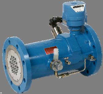
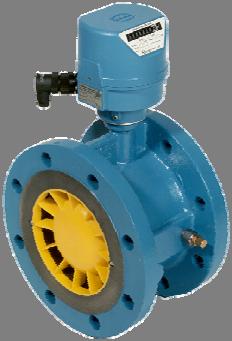
5 INTRODUCTION Introduction Scope of application The TRZ 03, TRZ 03-E and TRZ 03-L turbine meters are flow meters which can be used for custody transfer metering. Unlike these instruments, the TRZ 03-K turbine meter can only be used for secondary metering. All three types of turbine meters measure the quantity of gas flowing through them in units of volume at prevailing pressure and temperature. Therefore, the units of volume are determined at flowing conditions. The volume of the gas flowing through is indicated by a mechanical totalizer in cubic meters at flowing conditions. In addition, the turbine meters can be fitted with HF or LF pulse transmitters and with reed contacts. In this way, pulses are obtained whose number is proportional to the volume which has flowed through. These pulses can be further processed by volume correctors. 1 The major differences between types TRZ 03, TRZ 03-E, TRZ 03-K or TRZ 03-L are as follows: TRZ 03 Approved for custody transfer metering in compliance with DIN Einbaulänge: 3 x DN Installation length: 3 x DN Accuracy 0.5% (above 0.2 Qmax) Blade monitoring system TRZ 03-E Only with electronic pick-off, without mechanical totalizer. Approved for custody transfer metering in compliance with DIN Installation length: 3 x DN Accuracy 0.5% (above 0.2 Qmax) Blade monitoring system TRZ 03-K For secondary metering. Installation length: 1.5 x DN Accuracy 1% (above 0.2 Qmax) TRZ 03-L Approved for custody transfer metering in compliance with TR G13 / OIML. Requires no additional inlet pipe even in the case of heavy flow disturbances. Accuracy 0.5% (above 0.2 Qmax) Blade monitoring system The following applies to all meter types: Maximum operating pressure: 100 bar (not for gas meters with a plastic turbine wheel) Meter sizes from G 40 to G Measuring range 1:20; 1:30 or 1:50 (see data sheets) Connections in compliance with DIN or ANSI are available. Special designs for aggressive gases are available. Available for low temperatures (< 10 C) All gas meters can be operated in any position up to the nominal diameter of DN 200.
6 INTRODUCTION Method of operation 2 The method of operation of the mechanical turbine meter is based on the measurement of the gas velocity. The velocity of the gas flowing through the gas meter is increased in the flow straightener and the gas strikes the turbine wheel in a defined flow cross section. In the flow straightener, unwanted vortices, turbulences and asymmetries are removed or reduced. The turbine wheel is mounted axially, while the blades of the turbine wheel are arranged at a certain angle to the gas flow. Within the measuring range (Qmin - Qmax), the rotational speed of the turbine wheel is almost proportional to the mean gas velocity and, therefore, to the rate of flow. The number of rotations is a measure of the volume that has flowed through. The rotary movement of the turbine wheel is transmitted by a magnetic coupling to the unpressurized meter head. Downstream of the coupling, there is an HF pulse transmitter (HF 1) and gearing which reduces the rotational speed of the turbine wheel to match the mechanical totalizer. An LF pulse transmitter (slot-type initiator or reed contact) is located on the totalizer. Flow straightener Digital index High-frequencypulse transmitter HF 1 LF Low-frequencypulse transmitter Meter head type F Magnetic coupling Reference wheel High-frequencypulse transmitter Oil pump HF 3 HF 2 pr connection Turbine wheel Fig. 1: Sectional drawing of a turbine meter. Downstream of the turbine wheel, a cam wheel (reference wheel) is located on the same shaft. Two HF sensors (proximity switches) generate a signal if a blade of the turbine wheel (HF 3) or a cam of the reference wheel (HF 2) passes them. In this way, two pulse sequences are generated which are out of phase. The generated pulses can be further processed for secondary volume measurements or flow measurements.
7 INTRODUCTION Approvals Type TRZ 03 has been approved for custody transfer metering. The following approvals have been obtained: MID approval No. T10417 German approval No /93.06 DVGW registration No. CE-0085BN0291 Type TRZ 03-K has not been approved for custody transfer metering. The following approvals have been obtained: DVGW registration Nr. CE-0085BN Type TRZ 03-L has been approved for custody transfer metering. The following approvals have been obtained: EU approval Nr. D German approval No /98.11 DVGW registration No. CE-0085BN0291 Standards / Guidelines All RMG turbine meters have passed the disturbance measurements in compliance with OIML Recommendation IR-32/89, Annex A, with slight and heavy flow disturbances. Therefore, this meter design meets the requirements for installation in compliance with Technical Guideline G 131), Sec. 1. Test specifications are as laid down in PTB Testing Instructions, Vol. 4, Volume gas meters, 2nd revised edition of The RMG turbine meters of type TRZ 03 comply with DIN Validity of meter proving The turbine meters of type TRZ 03 which are suitable for custody transfer metering must be subjected to subsequent meter proving at regular intervals. The validity of meter proving is determined in the German Metering and Calibration Rules issued in 1988 (with amendment of September 24,1992) and extends to eight years for turbine meters without a lubricator. Since all RMG TRZ 03 turbine meters are fitted with a lubricator as standard, the following periods apply to subsequent meter proving: G 40 - G years G G years G and larger without limitation Note: these periods are valid for Germany, in other countries the periods are normally different! In the case of subsequent meter proving, the gas meter must be removed and tested on a test rig. 1) can be ordered at PTB, Bundesallee 100, D Braunschweig (
8 INTRODUCTION 4 Measuring ranges The measuring ranges are between 10 and 25,000 m 3 /h (flowing conditions). A measuring range is specified for each meter size. It is limited by the minimum flow rate Qmin and the maximum flow rate Qmax (see tables on pages 35 to 37). For types TRZ 03 and TRZ 03-L, this is the flow range where the gas meter must indicate correct values within the error limits specified by the German Metering and Calibration Rules. Turbine meters of type TRZ 03 have measuring ranges up to 1:30 even under atmospheric pressure. If a high-pressure test is conducted in compliance with Technical Guideline G 71) (PTB), the measuring range can be extended to 1:50. Then the minimum flow rate Qmin HP is the lowest test point during high-pressure testing. Types TRZ 03 and TRZ 03-L may then be used for billing purposes within the specified HP flow and density ranges. The measuring range of type TRZ 03-K is 1:16. Extension of the measuring range In the range of 0.2 Qmax to Qmax, the measuring behaviour of turbine meters is determined by the aerodynamic conditions in the flow channel and the measuring cross section. By means of many series of tests conducted both under atmospheric pressure and under higher pressures and with an appropriate rating for such ranges, it is possible to achieve a deviation of the calibration curve under atmospheric conditions and under high-pressure conditions of < 0.5% in the flow range of 0.2 Qmax to Qmax. In the lower flow range, the measuring behaviour is determined by the relationship between the gas flow driving the measuring wheel and the slowing-down torques due to drags (bearings and totalizer). The driving torques increase linearly with the density and quadratically with the velocity of the gas to be measured. Due to the physical conditions, the measuring range is therefore enlarged in relation to the density. The lower flow limit shifts in the direction of smaller loads (see also the table on page 38). Use the formula below as approximate equation: Q md Q min 1,2 (m 3 / h) The density can be determined with the following approximate formula: 3 (p 1) x (kg / m ) m n The influence of the temperature is not taken into account in this formula. Q md : Minimum flow rate at flowing conditions Q min : Minimum flow rate of the gas meter p m : Operating pressure in bar : Density in kg/m 3 n : Standard density of the gas (standard density of natural gas 0,8 kg/m 3 ) 1.2 Density of air at 20 C and bar (in kg/m³) 1) can be ordered at PTB, Bundesallee 100, D Braunschweig (
9 INTRODUCTION Accuracy of measurement The following error limits apply within the premissible measuring range: Measuring range: Qmin to 0.2 Qmax 0.2 Qmax to Qmax Calibration limit 1) 2 % 1 % TRZ 03, TRZ 03-L 1 % 0.5 % TRZ 03-K 2 % (DN 50, DN 80: 3 %) 1 % (DN 50: 1.5 %) 1) Permissible maximum error pursuant to the German Metering and Calibration Rules 5 It will be checked whether these limits are observed. They also apply to the high-pressure range % Fig. 1: Calibration curve of a turbine meter The reproducibility, i.e. the difference between the results of two measurements under identical conditions, is as follows: TRZ 03, TRZ 03-L, TRZ 03-K: 0.1% Temperature ranges For the standard designs of the turbine meters of types TRZ 03, TRZ 03-L and TRZ 03-K, the following fluid temperature and ambient temperature ranges are permitted: Fluid temperature range: -10 C to +50 C (TRZ 03 and TRZ 03-L for custody transfer metering) -10 C to +60 C (TRZ 03, TRZ 03-L and TRZ 03-K for secondary metering) Ambient temperature range: -10 C to +60 C (TRZ 03, TRZ 03-L and TRZ 03-K)
10 INTRODUCTION Pressure loss The pressure loss of RMG turbine meters has been reduced to a minimum thanks to modifications with regard to design. The measuring points for pressure loss are located 1 x DN upstream and downstream of the gas meter. The pressure loss is calculated using the following formula: 6 p Z p Q DN 2 m 4 where: p is the pressure loss [mbar] Zp is the pressure loss coefficient is the density [kg/m 3 ] Qm is the volume flow rate at measurement conditions [m 3 /h] DN is the nominal diameter of the gas meter [mm] Device type Zp TRZ 03 / TRZ 03-K turbine meter 3000 TRZ 03-L turbine meter 3600 L1 perforated-plate straightener as per ISO/DIN 3150 L2 perforated-plate straightener as per ISO/DIN 6300 L3 perforated-plate straightener as per ISO/DIN 9450 LP-35 perforated-plate straightener as per RMG 1260 standard RB 19 tube-bundle straightener as per ISO/DIN 1260 The values for Zp are approximate mean values. The exact value is calculated from the pressure loss which is determined on testing the volumeter. Example of calculation: Calculation of the pressure loss for a turbine meter with upstream perforated-plate straightener. TRZ 03, Qm = 650 m 3 /h, DN 150, = 1,3 kg/m 3 (natural gas) From the table: Zp(TRZ03) = 3000, Zp(LP-35) = 1260 Calculation: Zp(ges) = = 4260 p mbar 4 150
11 INTRODUCTION Pressure tap A pressure tap has been provided to connect the pressure transducer of a volume corrector or a pressure gauge to read the pressure at measurement conditions prevailing inside the gas meter. This pressure tap is identified by pr. Using gas meters with different types of gases Gas type Symbol Density Meter case Comments at 0 C bar Acid gas Special Special measuring element Air Ar 1.29 Standard Ammonia NH Standard O-rings/lubrication Argon AR 1.78 Standard Biogas Special Special measuring element Butane C4H Standard Carbon dioxide CO Standard Exception: food industry Carbon monoxide CO 1.25 Standard Ethan C2H Standard Ethylene (gaseous) C2H Standard Special design Freon (gaseous) CCI2F Standard O-rings/lubrication Helium HE 0.18 Standard Reduced measuring range Hydrogen H Special Reduced measuring range Hydrogen sulphide H2S 1.54 Standard Special measuring element (0.2 %) Methane CH Standard Natural gas 0.8 Standard Nitrogen N Standard Oxygen (100%) O Standard Special design Pentane C5H Standard Propane C3H Standard Propylene (gaseous) C3H Standard Special measuring element Sulphur dioxide SO Special Special design Town gas 7
12 SAFETY INSTRUCTIONS Safety Instructions The TRZ 03, TRZ 03-L and TRZ 03-K turbine meters are used for measuring the volume at measurement conditions of non-aggressive gases and fuel gases. Measurements of aggressive gases are only permitted if the special designs are used which have been developed for this purpose. These gas meters are not suitable for measuring liquids, otherwise they will be destroyed. 8 The TRZ 03, TRZ 03-L and TRZ 03-K turbine meters comply with currently applicable standards and regulations. However, failure to operate them properly may cause hazards. Persons who install or operate the TRZ 03, TRZ 03-L or TRZ 03-K turbine meters in areas subject to explosion hazards, must be familiar with the currently applicable standards and regulations with regard to explosion protection. The TRZ 03, TRZ 03-L and TRZ 03-K turbine meters have been approved for use in areas subject to explosion hazards and their code is: EEx ib IIC T6 The appropriate German certificate of conformity for the LF and HF sensors can be found in the annex. Please observe the following signs: Danger of explosion In the manual, this symbol warns you of an explosion hazard. Please observe the instructions given next to this symbol. As to the danger of explosion, please observe the following in particular: Connect the pulse outputs of the turbine meter only to intrinsically safe circuits. Damage to property In the manual, this symbol warns you of possible damage to property. The instructions given next to this symbol inform you about what you can do to avoid damage to the turbine meter. No warranty claims can be asserted if there is unauthorized interference with the device!
13 INSTALLATION AND COMMISSIONING Installation and Commissioning Installation Caution: Please read these installation instructions through and make sure that you have understood the procedure before you start to install the RMG turbine meter or put it into operation. Turbine meters are precise measuring instruments and must be handled carefully during transport, storage and operation. When you install the turbine meter, please observe the direction of flow indicated by an arrow on the meter case. 9 Installation errors may cause physical injuries or result in the destruction of the turbine meter. It is essential to follow the instructions below: Remove the yellow protective film at the flanges completely. Rests of this plastic film affect the flow profile and cause measuring errors! The RMG TRZ 03, TRZ 03-L and TRZ 03-K turbine meters can be operated in any position up to the nominal diameter of DN 200. From the nominal diameter of DN 250, however, only a horizontal direction of flow is possible. If a particular position was indicated when ordering the turbine meter, you must install the turbine meter in this position. In addition, you must make sure that the filling opening of the lubricator faces upwards. Any components affecting the gas flow must be avoided directly upstream of the turbine meter (see DVGW Guideline G 492 II1) and PTB Guideline G 132), exception: TRZ 03-L). An inlet pipe of a minimum of 2 x DN is required upstream of the RMG TRZ 03 turbine meter. The inlet pipe must be designed as a straight pipe section of the same nominal diameter as the gas meter. If there is a heavy flow disturbance, it is necessary to use flow straighteners (see table on next page). A pipe or fitting (bend) of the same nominal diameter as the gas meter and an overall length of 2 x DN must be installed downstream of the gas meter. Temperature measuring instruments may only be installed at a distance of 1 x DN or in the case of nominal diameters of DN 300 at a minimum distance of 300 mm. If there are flow disturbances (e.g. due to a gas pressure regulator) upstream of the inlet pipe, it is also necessary to use a perforated-plate straightener. You can use perforated-plate straighteners complying with ISO or of type RMG LP-35, the latter resulting in a pressure loss which is 2.5 times lower than that of the standardized flow straightener. 1) can be ordered at DVGW, Josef-Wirmer-Str. 1-3, D Bonn ( 2) can be ordered at PTB, Bundesallee 100, D Braunschweig (
14 INSTALLATION AND COMMISSIONING 2 DN LP-35 perforated-plate straightener 2 DN d DN d 10 1 DN Perforated-plate straightener d = e = 0.13 DN DN e Upstream of the RMG TRZ 03-L turbine meter, no inlet pipe is required, even in the case of heavy flow disturbances such as those caused by a gas pressure regulator. It has been tested without an inlet pipe in compliance with Technical Guideline G13 (which corresponds to the OIML Guideline IR-32/89). A pipe or fitting (bend) of the same nominal diameter as the gas meter and an overall length of 2 x DN must be installed downstream of the gas meter. Temperature measuring instruments may only be installed at a distance of 1 x DN or in the case of nominal diameters of DN 300 at a minimum distance of 300 mm. The opening angle of reducers or expansion fittings installed upstream of a turbine meter of type TRZ 03, TRZ 03-L or TRZ 03-K must not exceed 30. In order to obtain precise measurement results, the turbine meter must be installed in the gas line in such a way that no seals protrude from the flanges into the pipeline. A protective screen should be installed on the intake side of the gas meter to protect the turbine meter against any foreign particles possibly contained in the gas flow. The protective screen can be a perforated plate of sheet metal with a hole diameter of 3 mm which is available from RMG. The pr tap which is located on the RMG turbine meter is the pressure-measuring point which was used for taking the relevant pressure at measurement conditions during meter proving. This pressure-measuring point is used for connecting pressure-measuring instruments such as flow computers or volume correctors. Other connection options (e.g. for temperature measurement) can be supplied on a pipe section on the output side of the gas meter.
15 INSTALLATION AND COMMISSIONING Caution: Protect the turbine meter from damage caused by heavy flow variations, e.g. if the downstream pipeline system must be filled or blown off. Caution: If it is necessary to do welding work on the gas line, such work can only be performed at a safe distance from the gas meter. Extreme temperatures prevailing in the gas line in the proximity of the gas meter can result in a permanent damage to the gas meter. Caution: All electrical connections between the gas meter and the amplifiers or the flow computer must be carried out in compliance with the installation instructions. Make sure that these connections are intrinsically safe. Caution: Any liquids remaining in the gas line after hydrostatic testing can damage the interior parts of the gas meter. If hydrostatic testing is necessary, the turbine meter must be replaced by a pipe section. Make sure that no liquid remains in the gas line upstream of the gas meter after hydrostatic testing. 11 Operating data Recommended threshold values for maximum service life and maximum accuracy: Maximum overload: Maximum flow or shock loads Maximum pressure change: Maximum flow pulsation: < 5% Particle size in the gas flow: Lubrication of bearings Vibration / mechanical shock: < 20% above Qmax, for a short time (< 30 sec) < 0.01 Qmax/sec ˆ 1% of Qmax/sec e.g. starting up 0-100%: > 100 sec < 0.1 bar/sec < 5 m See chapter on Lubrication. Lubrication intervals depend on the condition of the gas (condensate, rust or dust) < 1 mm/sec (vibration velocity) These specified data must be determined and checked during commissioning, prior to filling and during the start-up and running-in phases of the gas meters. If more than one threshold value occurs at the same time, appropriate action must be taken in the station to improve the measuring conditions. The operator must record all measuring data (gas meter and operating data) during the whole period of operation in order to detect the causes of a possible destruction of the gas meter at an early stage and take corrective action in good time.
16 INSTALLATION AND COMMISSIONING 12 Corrective action or reduction of the critical operating conditions can be achieved by the following measures for example: Start-up screens (mesh width < 0.15 mm) Filters Perforated plates (Ø 3-4 mm) protecting the gas meter Valves with control drive mechanism (flow variation) Non-return valves (pulsation and return flow) Technical Guideline G 13 The installation conditions for new stations complying with TRG G 13 and the simpler installation conditions for RMG turbine meters are compared in the table below. Type of flow disturbance Installation cond. As per TR G13 Installation cond. for RMG gas meters Type TRZ03 Comments Gas pressure regulator with sound attenuator Gas pressure regulator without sound attenuator Diffuser Diffuser with swirling flow Inlet pipe 5 DN Outlet pipe 2 DN Inlet pipe 2 DN Outlet pipe 2 DN The outlet pipe can also be designed as a bend. None Inlet pipe 10 DN Flow disturbances upstream of this inlet pipe need not be considered, if the requirement for an alternating and pulsating flow is fulfilled. Bend Inlet pipe 5 DN Inlet pipe 2 DN Space bend Inlet pipe 5 DN and additionally 2 perforated-plate straighteners or one tube-bundle straight- Inlet pipe 2 DN ener Inlet pipe 5 DN Inlet pipe 5 DN and additionally two perforated-plate straighteners Inlet pipe 5 DN and additionally one perforated-plate straighteners Inlet pipe 5 DN and additionally two perforated-plate straighteners Inlet pipe 2 DN and additionally one perforated-plate straightener Inlet pipe 2 DN and additionally one perforated-plate straightener Inlet pipe 2 DN Inlet pipe 2 DN
17 INSTALLATION AND COMMISSIONING Perforated-plate straighteners There are the following options for flow straighteners: RMG L1 - L3 perforated-plate straighteners complying with ISO and DIN 1952 RMG LP-35 perforated-plate straightener e 13 d D d D a D e Features ISO / DIN L1 to L3 RMG LP-35 Hole diameter d d 0.05 D 0.04 D 0.13 D Plate thickness e e d e = d 0.13 D Plate clearance a 0.5 D a 1 D 0.5 D - Opening ratio m 0.2 m Pressure loss, dyn. p 5-15 (c² / 2) 2-15 (c² / 2) In conjunction with RMG turbine meters, these flow straighteners fulfil the requirements of Technical Guideline G 13 and are approved under EU approval No. D 81 / for turbine meters.
18 INSTALLATION AND COMMISSIONING 14 Seals It must be guaranteed that flange seals of RMG turbine meters do not protrude from the flange into the gas line. All seals approved as per DVGW can be used depending on the requirements for stability and reliability. We recommend seals with the following maximum material characteristic values according to the AD2000 rules: gaskets: k0 x KD = 20 x bd k1 = 1.3 x bd [N/mm] grooved seals: k0 x KD = 15 x bd k1 = 1.1 x bd [N/mm] spiral seals: k0 x KD = 50 x bd k1 = 1.4 x bd [N/mm] octagonal ring joint seal: KD = 480 N/mm2 For recommended dimensions, see the tables below. d1 1.5 up to 5 mm d2 Gaskets PN 10 PN 16 ANSI 150 PN 25 PN 40 DN d1 d2 50 2" " " " " " " " " " Grooved seals ANSI 300 / ANSI 600 PN 64 DN d1 d2 d1 d2 50 2" " " " " " " " "
19 INSTALLATION AND COMMISSIONING Spiral seals ANSI 300 PN 64 ANSI 600 DN d1 d2 D1 d2 d1 d2 50 2" " " " " " " " " " Screws Temperature ranges for screws and nuts -10 C to +80 C -40 C to +80 C Pressure Variant 1 Variant 2 Variant 3 up to and including 40 bar from 40 bar Screws complying with DIN EN ISO 4014 made of material 5.6, Nuts complying with DIN EN ISO 4032 made of material 5-2 Screw bolts complying with ANSI B1.1 made of material ASTM A193 Grade B7, Nuts complying with ANSI B1.1 made of material ASTM A194 Grade 2H Screws complying with DIN EN ISO 4014 made of material 25CrMo4, Nuts complying with DIN EN ISO 4032 made of material 25CrMo4 Screw bolts complying with ANSI B1.1 made of material ASTM A320 Grade L7, Nuts complying with ANSI B1.1 made of material ASTM A320 Grade L7 Screw bolts complying with ANSI B1.1 made of material 42CrMo4, Nuts complying with ANSI B1.1 made of material 42CrMo4 Anti-fatigue bolts complying with DIN 2510 made of material 25CrMo4, Nuts complying with DIN 2510 made of material 25CrMo4


20 INSTALLATION AND COMMISSIONING Types of totalizers The RMG turbine meter can be fitted with different totalizers. 16 Type A meter head Type D meter head Type F meter head Type F meter head The new standard design is type F meter head without mechanical drive shaft couplings. Therefore, this design provides no options for connecting additional mechanical equipment. The totalizer has the following features: LF pulse transmitter - Standard: reed contact - Alternatively: inductive pulse transmitter - Option: up to two additional inductive LF pulse transmitters HF pulse transmitters are optionally available, pulse frequency approx. 100 Hz at Qmax IP 65 protection class Universally readable Totalizer unit and HF 1 pulse transmitter are easily replaceable on site. The electrical connector must be covered by a cap closure or a connecting plug! Otherwise moisture may ingress into the meter head. Type F-D meter head Design and features like in the case of the type F meter head but additional with a mechanical drive shaft in compliance with EN on the top side of the case. The direction of rotation of the drive shaft (with view on the drive shaft) is clockwise. For dimensions and instructions for the connection see the description of the type D meter head. Especially note the maximum permissible torques!
21 INSTALLATION AND COMMISSIONING Permissible torques (type F-D ) Nominal dia. Sizes Qmax Qmin [m 3 /h] Mmax [Nmm] DN G m3/h 1:20 1:10 1:5 1:20 1:10 1: Type A meter head The old standard design is type A meter head without mechanical drive shaft couplings. This design provides no options for connecting additional mechanical equipment. The totalizer has the following features: LF pulse transmitter - Standard: reed contact - Alternatively: inductive pulse transmitter HF pulse transmitter is optionally available, pulse frequency approx. 100 Hz at Qmax
22 INSTALLATION AND COMMISSIONING 18 Type D meter head Type D meter head provides two mechanical drive shafts where additional equipment, e.g. slip-on pulse transmitters, volume correctors, etc., can be attached under official supervision. Before you connect additional mechanically driven equipment, you must make sure that the direction of rotation and the rotation rate Ua (see Specifications of the gas meter) comply with the data on the gas meter. The torque required for driving the additional equipment must not exceed the value stated on the indicating plate of the drive shaft. Do not use the protruding totalizer of type D meter head as a handle to carry the gas meter during transport. The totalizer has the following features: LF pulse transmitter - Standard: reed-contact - Alternatively: inductive pulse transmitter - Option: one additional inductive pulse transmitter HF pulse transmitters are optionally available, pulse frequency approx. 100 Hz at Qmax Additional mechanical equipment can be connected. Direction of rotation: clockwise Counterclockwise b Clockwise a c Type "D" meter head Direction of rotation of the drive shafts Dimensions of the drive shaft coupling Connection of additional equipment The drive shaft couplings of the meter head (type D ) can be used for connecting additional mechanical or electronic measuring instruments. In this case, the total driving torque must not exceed the approved value. If no additional equipment is used, the drive shaft couplings are sealed. The rotation rates of the drive shaft coupling depend on the meter size (see table). Note Additional equipment or additional measuring instruments can only be attached or removed under official supervision. Before you connect additional equipment, make sure that the direction of rotation and the rotation rate of mechanical transmission coincide. Depending on the location for attaching additional equipment, you can turn the meter head into the most favourable position for installation without damaging the locking seals by loosening two hexagon socket screws.
23 INSTALLATION AND COMMISSIONING Permissible torques (type D ) Due to the fact that the measuring range of turbine meters can be adversely affected by the torque of additional mechanically driven equipment, the permissible maximum torques in Nmm stated in the table below apply in relation to the flow range and the nominal diameter. Sizes Nominal dia. DN Q max m3/h Q min m3/h M max Nmm P max bar G G G G G G G G G G G G G G G G G Q max 16 G Q max Q max 98 19
24 INSTALLATION AND COMMISSIONING General After you have loosened the two locking screws located on both sides of the meter head, you can turn all meter head designs (types A, D and F) through 350 to reach an optimum position for taking meter readings. To do this, you need an SW 2 hexagon socket wrench. 20 Type A meter head Locking screw Type D meter head Locking screw Type F meter head If work has to be done on the meter head, please make sure that the official seals are not damaged.
25 INSTALLATION AND COMMISSIONING Pulse transmitters The TRZ 03, TRZ 03L and TRZ 03-K turbine meters provide different sensors which supply volume pulses in a variety of frequency ranges. These pulses can be further processed by volume correctors or remote totalizers, for example. All pulse transmitters of the TRZ 03 and TRZ 03L have been approved for custody transfer metering. The connection options are shown in the following illustration. 21 Connection options E 1 Servo-actuator Volume corrector LF HF1 E Gas flow recorder Remote totalizer Printer Maximum-value recorder HF3 HF2 E D E A ma (0-4 ma) (4-20 ma) Min./max. contact flow indicator 3 [Ex] E E 1 non [Ex] Volume corrector 1 EEx i isolating amplifier 2 Digital-to-analog converter 3 Blade monitoring system All pulse transmitters are intrinsically safe and must be connected only to intrinsically safe circuits if they are used in areas subject to explosion hazards. The safety barriers must meet the requirements of the EEx ib IIC type of protection. Pulse transmitters in the meter head (LF and HF 1) The meter heads of the RMG TRZ 03, TRZ 03K and TRZ 03L turbine meters are fitted with a reed contact as standard. The pulse value corresponds to the rotation rate Ua. See the indicating plate on the meter head for exact frequency data. The guide values are given in the tables on pages 35 through 37. The maximum pulse frequency is 0.3 Hz. Optionally, a slot-type initiator can be installed. In applications where a higher resolution is required, an additional HF 1 pulse transmitter can be installed. Then the maximum pulse frequency will be of the order of approx. 300 Hz at Qmax. The connector pin assignments for the standard design with a reed contact (alternatively, with a slottype initiator) are shown in the illustration below. Please also note the indicating plate on the meter head.
26 INSTALLATION AND COMMISSIONING LF and HF 1 Slot-type initiator (option, NAMUR) Connector Slot-type initiator 22 LF (f max =0.3 Hz) HF (f max=300 Hz) (NAMUR) Reed contact (f =0.3 Hz) max Pulse transmitters in the measuring element (HF 2 and HF 3) The higher-frequency flow signals from the HF 2 and HF 3 proximity sensors are used for control purposes and in conjunction with electronic flow computers suitable for custody transfer metering. In the case of the HF 3 pulse transmitter, the pulses are picked off at the turbine wheel, while they are picked off at the reference wheel for the HF 2 pulse transmitter. The two wheels are arranged in such a way that two pulse series of the same frequency are generated which are out of phase by 180. The exact frequency is determined during meter proving and is stated on a supplementary data plate on the meter case. The guide values are listed in the tables on pages 35 through 37. The maximum pulse frequency is approx Hz at Qmax, but depends on the meter size. Connector HF 2, HF Proximity switch 2 1 HF 2: reference wheel HF 3: turbine wheel f max = 2.1 khz (NAMUR) Connections are made by means of multi-pin connectors. Normally, an LF pulse transmitter is connected to contacts 1 and 4, while a single HF 1 pulse transmitter is connected to contacts 3 and 6. Here the highest number is always (+). High-frequency pulse transmitters which go with the turbine wheel (HF 2) or the reference wheel (HF 3) are usually connected to contacts 1 and 3 (for older devices 1 and 6).
27 INSTALLATION AND COMMISSIONING Connector pin assignments Connector, 3 pins (HF2/HF3) Produced by Binder (series 713) HF signal Namur 23 Connector, 7 pins (meter head F, HF2/HF3 for older devices) 4 3 Produced by Binder (series 693) LF signal reed or Namur 5 6 PE (screen) optionally, LF or HF signal HF signal Namur Connector, 4 pins (for older devices) produced by Hirschmann 3 PE LF signal reed or Namur Connector, 6 pins (for older devices) produced by Harting LF signal reed or Namur Here the cable connector is depicted. (Connecting part is provided by the customer.) optionally, LF or HF signal HF signal Namur
28 INSTALLATION AND COMMISSIONING Specifications of the pulse transmitters Electrical data 24 Reed contact Contact as make-contact element Max. contakt load Max. switching voltage Max. switching current fmax 10 W 200 VDC 0,5 A 0,3 Hz LF-slot-type initiator Inductive proximity switch complying with DIN (NAMUR) Supply voltage 7 to 9 VDC (with internal resistance Ri = 1 k) Current if switch is not operated 3 ma Current if switch is operated 1 ma 0.3 Hz fmax HF 1 slot-type initiator Inductive proximity switch complying with DIN (NAMUR) Supply voltage 7 to 9 VDC (with internal resistance Ri = 1 k) Current if switch is not operated 3 ma Current if switch is operated 1 ma 300 Hz fmax HF 2 slot-type initiator Inductive proximity switch complying with DIN (NAMUR) Supply voltage 7 to 9 VDC (with internal resistance Ri = 1 k) Current if switch is not operated 3 ma Current if switch is operated 1 ma 2100 Hz fmax
29 INSTALLATION AND COMMISSIONING Temperature measurement In order to measure the gas temperature, a resistance thermometer can be used in a thermowell in a fitting downstream of the gas meter. It is recommended that a second thermowell, e.g. for a monitoring thermometer, be used. If such thermowells are not provided for in the meter case, temperature measurement must be performed at a distance of up to 3 x DN or a maximum of 600 mm downstream of the turbine meter. All turbine meters of types TRZ 03 and TRZ 03-L from the nominal diameter of DN 80 (3") upwards can be fitted with a thermowell for a PT100 resistance thermometer. Due to their short size, turbine meters of type TRZ 03-K cannot be fitted with a thermowell. 25 Operating temperatures prevailing at outdoor metering stations in winter or at natural gas metering stations downstream of regulating stations are usually in the range of -5C to +10C. By comparison, higher operating temperatures prevail at metering stations located downstream of compressor stations. For this reason, the measuring elements of the temperature sensors located outside the gas line must be appropriately insulated against the weather. In order to achieve optimum thermal conduction, oil as a heat transfer liquid should be filled in the thermowells in any case.
30 INSTALLATION AND COMMISSIONING Commissioning 26 Filling with oil When the turbine meters are delivered, the lubricators do not contain any oil. The oil pumps must not be filled with oil until they are at the installation site prior to commissioning! A small bottle of oil is supplied with each gas meter. Then you have to perform an initial lubrication. For this see the detailed lubrication instructions in chapter Lubrication from page 29. Connecting the gas flow Do not fill any downstream pipelines or station sections through the turbine meter. This may speed up the turbine wheel and lead to excessively high loads with resultant damage. Short-time overload operation of 20% above the maximum flow rate Qmax is permissible. Such load conditions should be avoided, however, since in most cases they cannot be controlled and exceed the officially approved limits for custody transfer metering. Moreover, such overloads reduce the service life of the gas meter. The gas flow must be free of foreign particles, dust or liquids. Otherwise it is recommended that filters or separators be installed.
31 OPERATION Operation Influences on the error of measurement due to operation Intermittent operation Rapid changes of the gas flow should be avoided, since the turbine wheel can follow these changes only with a certain delay due to its inertia. In this way, errors of measurement occur, in particular, if the gas flow is shut off. Since in this case the turbine wheel slows down after the flow has stopped, a gas volume is measured which is always higher than that which has actually flowed through the gas meter. 27 In the supplement to PTB Guideline G 13, an instrument is stipulated which records the flow during the slow-down time of the turbine wheel for intermittent operation (i.e. if the gas flow is permanently switched on and shut off). If control signals of a shut-off valve are available, this volume can be recorded by a suitable data logger (if there is a TAZ 9 installed in an older station, this RMG device records the slow-down volume for custody transfer metering purposes with the TRZ 03 or TRZ 03-L). Influence of pulsations The gas flow must be free of shocks or pulsations. A gas metering station can be affected by flow pulsations, however, if the following equipment has been installed upstream or downstream in the system: reciprocating piston compressors, rotary displacement meters, gas pressure regulators lacking steadiness of operation, pipes where no gas flows (siphons). Volume flow pulsation is the decisive quantity for evaluating the performance of gas meters under the influence of pulsations. Volume flow pulsation is physically always associated with pressure variations. The following relation is established in a first approximation: relp rel Q DN Q 2 K Q^rel: is the relative volume flow pulsation (peak-to-peak) Q : is the mean volumetric flow p ^rel : is the relative pressure pulsation (peak-to-peak) DN: is the nominal diameter of the gas meter K: is a constant depending on standard density, velocity of sound, compressibility, pressure at base conditions, temperature, and station-specific parameters.
32 OPERATION With this relation, it is possible to estimate volume flow pulsation on the basis of pressure pulsation, which can be measured more easily. Direct measurement of volume flow pulsation is preferable, however, since the results are more reliable. The crucial factor is the pulsation at the location of measurement. 28 Consequences In the case of pulsating flow, the turbine meter shows a measured value which is too high. Due to the pulse applied by the flow on the impeller which increases quadratically with the flow velocity, the resultant rotational speed is higher than the mean value of the flow velocity. The influence with high gas density is less, but increases with a high mass moment of inertia (heavy impeller) or fast-running wheels. Furthermore, high pulsation amplitudes may result in premature wear of shaft bearings due to increased load. Limiting values Frequency ranges It is generally unlikely that measured values will be distorted in the frequency range above 100 Hz. In practice, it is hardly possible to initiate any significant flow variations at such frequencies. Disturbances are to be expected most frequently in the frequency range between 0.1 Hz and 100 Hz, since with typical station dimensions, the gas column can be expected to produce resonances. Flow variations with a high relative amplitude may occur. In the frequency range below 0.1 Hz, there is a quasi-steady flow which will not cause any distortion with the gas meters. Pulsation amplitudes Studies have shown that no disturbances are to be expected in the case of relative flow pulsations below 5% (peak-to-peak) and relative pressure pulsations of less than 0.1% to 0.5% (peak-topeak). These data should be regarded as approximate values depending on the flow rate and pulsation frequency involved.
33 OPERATION Lubrication Lubricator For lubrication, either an oil gun or a permanently fitted oil pressure pump is used. The various designs are given in the tables below. Type of oil pump Container volume Delivered quantity DO Oil gun (oil nipple) 150 cm cm 3 /stroke KO Pushbutton pump 8 cm cm 3 /stroke GO Lever pump 150 cm cm 3 /stroke DS Permanent lubrication TRZ 03-K TRZ 03 and TRZ 03L Pressure classes Pressure classes DN PN 10, 16 ANSI 150 PN 25, 40, 64, 100 ANSI 300, 600 PN 10, 16 ANSI 150 PN 25, 40, 64, 100 ANSI 300, DS (KO) 1) KO DS (KO) 1) KO 80 DS (KO) 1) KO DS (KO) 1) KO 100 DS (KO) 1) KO DS (KO) KO 150 DS (KO) 1) KO DS (KO) KO 200 KO KO 250 KO GO GO 300 GO GO 400 GO GO 500 GO GO 600 GO GO 1) meters manufactured before November 2007 with DO Types in brackets are options Specification for lubricating oils For lubrication purposes, we recommend that you use only Shell Tellus S2 MA 10 or another lubricating oil with 2 to 4 E at 25 C complying with MIL-L-6085-A in order to avoid damage to the shaft bearings. You can order your supply of lubricating oil from us in 1-liter containers under Ref. No Shelf life of oil: the shelf life depends on the operating conditions (e.g. UV light, humidity etc.). In principle the oil suffers no quality loss during the first 3-4 years. Initial lubrication When the turbine meters are delivered, the lubricators do not contain any oil. The oil pumps must not be filled with oil until they are at the installation site prior to commissioning. A small bottle of oil is supplied with each gas meter. For the initial lubrication more pump strokes are necessary than for the relubrications because first the oil pipes have to be filled with oil. Pump DN 50 DN 200 DN 250 DN 600 DO (oil gun) 20 strokes *) - KO (pushbutton pump) 40 strokes 45 strokes GO (lever pump) - 10 strokes *) after venting the oil gun!
34 OPERATION Relubrication The relubrication intervals are stated on a indicating plate on the meter case. See also Lubrication procedure. Example: 30 Relubrication! Every 3 months 2 strokes Lubricating oil: 2-4 E at 25 C conforming to MIL-L-6085-A see operating instructions In the case of unfavourable operating conditions, such as condensate forming because of water or hydrocarbon, or dust-laden gas, or service temperatures above 50 C, we recommend that lubrication be performed at shorter intervals, even daily under extreme conditions (permanent formation of condensate). If the gas meter is operated under the above-mentioned conditions, it is likely that its service life will be reduced. If you have questions to the relubrication in such cases please contact RMG. Lubrication procedure To fill the pumps and lubricate the turbine meters, proceed as follows: Oil gun (DO) Cover Piston To fill with oil: 1. Unscrew cover 2. Pull piston by means of the chain. 3. Fill with oil. 4. Reinsert piston by pushing it as far as possible. 5. Screw on cover again tightly. 6. Vent the oil gun! To lubricate: 1. Plug oil gun onto oil nipple. 2. Depress oil gun towards oil nipple once for each stroke. Every 3 months 2 strokes
35 OPERATION Pushbutton pump (KO) To fill with oil 1. Unscrew cover. 2. Fill with oil. 3. Screw on cover again. To lubricate: 1. Unscrew knurled cover (or hexagon cover in the case of older designs). 2. Depress pushbutton, which is now visible, once for each stroke. 3. Screw on knurled (or hexagon) cover again. 31 Every 3 months 6 strokes Lever pump (GO) To fill with oil: 1. Pull off cover upwards (in the case of lever pumps with transparent container, unscrew cover). 2. Fill with oil. 3. Screw (or plug) on cover again tightly. To lubricate: 1. Move lever once for each stroke as far as it will go. Up to DN 400: every 3 months 2 strokes From DN 500: every 3 months 3 strokes
36 OPERATION Maintenance instructions 32 RMG turbine meters are maintenance-free except that they require lubrication at regular intervals. Since all gas meters fitted with oil pumps are shipped with an empty oil storage tank, it is absolutely essential to fill the storage tank of the oil pump with oil and perform the initial lubrication before the gas meter is put into service (see section Lubrication ). The operator should nevertheless check the turbine meter at regular intervals. In this connection, please refer also to DVGW code of practice G 4951). (Gas pressure regulators for monitoring and servicing large-scale gas metering systems) The gas meter should be checked for accuracy approximately every two years depending on whether it is possible or necessary to perform such checks. This can be done as follows: In the station itself by connecting two gas meters in series. In an officially acknowledged testing laboratory for gas measuring instruments. In the factory. Labelling All important data which are necessary for operating the gas meter are stated on the plates which are affixed to the meter case, totalizer or pulse transmitters. Turbine meter type TRZ 03 G Q max ser.no. year m³/h Q min P max D MESSTECHNIK GMBH Germany DIN-DVGW NG-4702BL0600 m³/h bar Main data plate of the TRZ 03 turbine meter with type F meter head Turbine meter Type TRZ 03 G Qmax Qmin P max m³/h m³/h bar D Main data plate of the TRZ 03 turbine meter with type A meter head ser. no. year 1) can be ordered at DVGW, Josef-Wirmer-Str. 1-3, D Bonn (
Volumeter. RMG Meßtechnik GmbH. Publication No E
 Volumeter TRZ 03-K RMG Meßtechnik GmbH Publication No. 3.171-E P.O.Box 80 D-3550 Butzbach (Germany) Phone: +49 (0)6033 897-0 Fax: +49 (0)6033 897-130 E-mail: messtechnik@rmg.de Web site: http://www.rmg.de
RMG Meßtechnik GmbH. Publication No E
 Turbine meter TRZ 03 RMG Meßtechnik GmbH Publication No. 3.161-E P.O.Box 80 D-3550 Butzbach (Germany) Phone: +49 (0)6033 897-0 Fax: +49 (0)6033 897-130 E-mail: messtechnik@rmg.de Web site: http://www.rmg.de
Volumeter TRZ 03-K PRODUCT INFORMATION. Reliable Measurements of Gas
 Volumeter TRZ 0-K PRODUCT INFORMATION Reliable Measurements of Gas Method of operation, Construction Method of operation The TRZ 0-K Volumeter is a flow meter suitable for metering gases, where the rate
Rotary Displacement Meter RMG 132-A
 Rotary Displacement Meter RMG 132-A OPERATING INSTRUCTIONS Serving the Gas Industry Worldwide STATUS FEBRUARY 2011 by Honeywell Note: Unfortunately, paperwork does not automatically update itself but technical
Rotary Displacement Meter DKZ 02
 Rotary Displacement Meter DKZ 02 OPERATING INSTRUCTIONS Serving the Gas Industry Worldwide STATUS APRIL 203 by Honeywell Note: Unfortunately, paperwork does not automatically update itself but technical
Note: Boldrin reserves the right, to modify the gas meters without changing the request concerning accuracy and security. page 2
 Manual 0. List of contents 1. Design and Function 1.1. Description 1.2. Function 1.3. Meter sizes 1.4. Dimensions 1.5. Construction 1.5.1. Main housing 1.5.2. Measuring cartridge 1.5.3. Counter head 1.5.4.
Quantometer MZ. Description
 Quantometer MZ < High accuracy budget meter < Flow rate up to 10000 m 3 /h < Pressure range up to 100 bar < Equipped as standard with the cyble target. < Various options available: Low and high frequency
Internet
 Manual 0. List of contents 1. Design and Function 1.1. Description 1.2. Function 1.3. Meter sizes 1.4. Dimensions 1.5. Construction 1.5.1. Main housing 1.5.2. Measuring cartridge 1.5.3. Counter head 1.5.4.
FLUXI 2000/TZ Instruction manual Mode d emploi Betriebsanleitung Istruzioni d uso Manual de instrucciones Installatie voorschrift
 FLUXI 2000/TZ 652-099-2025 Instruction manual Mode d emploi Betriebsanleitung Istruzioni d uso Manual de instrucciones Installatie voorschrift ANNEX 6: CE Certificate of Conformity declares that the product:
Type 3761 Pneumatic or Electropneumatic Positioner for Rotary Actuators. Fig. 1 Type 3761 Positioner. Mounting and Operating Instructions EB 8386 EN
 Type 3761 Pneumatic or Electropneumatic Positioner for Rotary Actuators Fig. 1 Type 3761 Positioner Mounting and Operating Instructions EB 8386 EN Edition July 2007 Contents Contents Page 1 Design and
MZ Instruction manual Mode d emploi Betriebsanleitung Istruzioni d uso Manual de instrucciones Installatie voorschrift
 90 D C MZ 002-099-4115 Instruction manual Mode d emploi Betriebsanleitung Istruzioni d uso Manual de instrucciones Installatie voorschrift CE Certificate of Conformity Actaris Gaszählerbau GmbH 76161 Karlsruhe
Solenoid Valves Type 3963
 Mounting and Operating Instructions Solenoid Valves Type 3963 Fig. 1 General Assembly, commissioning and operation of these devices may only be performed by experienced personnel. Proper shipping and appropriate
Turbine Meters. df5/99 TRZ
 TRZ Topics Products History Features Quality Meter Comparison Calibration Installation Maintenance Summary Dr. H. Dornauf Product Manager Products Custody Transfer Turbine Meter ETM TRZ TRZ-IFS In-Plant
CONTOIL VZFA/VZOA , versions for higher requirements / applications
 CONTOIL VZF/VZO 4...50, versions for higher requirements / applications For applications requiring an increased accuracy of ±0.5 % or better, such as: Measurement of L heating fuel or diesel in testing
Fluxi 2000/TZ Turbine Gas Meter
 Fluxi 2000/TZ Turbine Gas Meter Turbine gas meters are flow meters. The flow of gas turns a turbine wheel, and thus, the rotating speed of the turbine is proportional to the linear speed of the gas. The
Axial Turbine Flow Sensor Series Turbotron VTH 25 / VTI 25 / VTM 25
 Installation Instruction Axial Turbine Flow Sensor Series Turbotron VTH 25 / VTI 25 / VTM 25 Table of contents Page 1 Function of Turbotron 1 2 Safety instructions 2 3 Important notes and requirements
Pneumatic or Electropneumatic Positioner for Rotary Actuators Type Fig. 1 Type 3761 Positioner. Mounting and Operating Instructions EB 8386 EN
 Pneumatic or Electropneumatic Positioner for Rotary Actuators Type 3761 Fig. 1 Type 3761 Positioner Mounting and Operating Instructions EB 8386 EN Edition June 2004 Contents Contents Page 1 Design and
Installation and Operational Instructions for EAS - HTL housed overload clutch Sizes 01 3 Type 490._24.0
 Please read these Operational Instructions carefully and follow them accordingly! Ignoring these Instructions may lead to malfunctions or to clutch failure, resulting in damage to other parts. Contents:
Oriflow. Compact Orifice with HART communication. Operating instructions. A-EN RevC Latest Mod von 16
 Compact Orifice with HART communication Oriflow Operating instructions Bopp & Reuther Messtechnik GmbH Am Neuen Rheinhafen 4 67346 Speyer - Germany Phone +49 (621) 657-0 Fax +49 (621) 657-505 http://www.bopp-reuther-mt.de
VersaFlow Vortex 100 Vortex Flow Meter Specifications
 VersaFlow Vortex 100 Vortex Flow Meter Specifications 34-VF-03-05 May 2011 The All-In-One Solution The VERSAFLOW is the only vortex flowmeter with integrated and temperature compensation in 2- wire technology.
Operating Instructions. VEGASWING 61, 63 with oscillator SW E60N (EX)
") Operating Instructions VEGASWING 61, 63 with oscillator SW E60N (EX) Contents Contents Safety information... 2 Note Ex area... 2 1 Product description... 3 2 Function and application... 4 2.1 Principle
Operating Instructions VEGASWING 61, 63 with oscillator SW E60N (EX) Contents Contents Safety information... 2 Note Ex area... 2 1 Product description... 3 2 Function and application... 4 2.1 Principle
Turbine meter. Operating manual. A-EN Rev.E 11/2013. Page 1 of 16
 Turbine meter with pulse pick-up RQ AG81/82/83 Operating manual Bopp & Reuther Am Neuen Rheinhafen 4 67346 Speyer Germany Phone : +49 (6232) 657-0 Fax: +49 (6232) 657-505 info@bopp-reuther.de www.bopp-reuther.de
Fluxi 2000/TZ Turbine Gas Meter
 Fluxi 2000/TZ Turbine Gas Meter Turbine gas meters are flow meters. The flow of gas turns a turbine wheel, and thus, the rotating speed of the turbine is proportional to the linear speed of the gas. The
Mounting and operating instructions EB 5801 EN. Electric Actuators Type 5801 (Rotary Actuator) Type 5802 (Linear Actuator)
 Type 5802 (Linear Actuator)") Electric Actuators Type 5801 (Rotary Actuator) Type 5802 (Linear Actuator) Linear Actuator with Type 3260 Control Valve Rotary actuator with lever system Linear actuator with Type 3321 (V2001) Control
Electric Actuators Type 5801 (Rotary Actuator) Type 5802 (Linear Actuator) Linear Actuator with Type 3260 Control Valve Rotary actuator with lever system Linear actuator with Type 3321 (V2001) Control
Magnetic-inductive flow meter for hazardous areas
 Magnetic-inductive flow meter for hazardous areas Technical Datasheet EPX / UMF3 high accuracy: 0.3 % of actual maintenance-free no pressure drop numerous lining materials numerous electrode materials
Delta Commercial & Industrial Rotary Meter
 Delta Commercial & Industrial Rotary Meter Itron's Delta range of rotary gas meters comprises innovative and high quality products. Characterized by compact dimensions and easy maintenance, the Delta
VQ400M SERIES CLASS A COMBINATION VALVES PRODUCT HANDBOOK APPLICATION
 VQ400M SERIES PRODUCT HANDBOOK APPLICATION The VQ400M Series class A safety combination valves are used for control and regulation of gaseous fluids in gas power burners, atmospheric gas boilers, melting
SITRANS P measuring instruments for pressure
 Overview Application The pressure transmitter is designed for the special requirements of the food, pharmaceutical and biotechnology industries. The use of high-grade materials guarantees compliance with
BARTON 7400 Precision Gas Turbine Flow Meters
 TECHNICAL SPECIFICATIONS BARTON 7400 Precision Gas Turbine Flow Meters BARTON Model 7400 Precision Turbine Flow Meters are designed for gas service in a wide range of industrial, commercial, pipeline and
ULTRASONIC FLOW SENSOR IFX-M4-01
 ULTRASONIC FLOW SENSOR IFX-M4-01 TECHNICAL DESCRIPTION, OPERATING INSTRUCTION IFX-M4-01 2012-09-10 TABLE OF CONTENTS 1. APPLICATION... 3 2. TECHNICAL DATA... 4 3. PACKAGE CONTENT... 6 4. OPERATING PRINCIPLE...
Level Measurement based on Archimedes Principle. Device Description
 Level Measurement based on Archimedes Principle BA Device Description Contents 1 IDENTIFICATION...4 1.1 Supplier/manufacturer...4 1.2 Product type...4 1.3 Product name...4 1.4 Issue date...4 1.5 Version
EB EN. Type 3372 Electropneumatic Actuator. Translation of original instructions
 EB 8313-1 EN Translation of original instructions V2001-IP Control Valve Type 3372 0511/0531 Electropneumatic Actuator with Type 3321 Valve Type 3372 Electropneumatic Actuator Edition July 2013 Note on
Safety. Operating instructions Solenoid valve for gas VG 6 VG 15/10 DANGER. Contents WARNING CAUTION. Changes to edition 07.15
 17 Elster GmbH Edition 1.17 Translation from the German 519 D F NL I E DK S N P GR TR CZ PL RUS H www.docuthek.com Operating instructions Solenoid valve for gas VG VG 15/1 Contents Solenoid valve for gas
INLINE Flow sensor for hazardous area II 1 G/D - II 2 D - II 3 GD - I M1
 INLINE Flow sensor for hazardous area II G/D - II D - II GD - I M Type SE0 Ex can be combined with... Flow meter with NAMUR or NPN/PNP output signal Mounting, dismounting of electronics by a Quarter-Turn
Safety. Operating instructions Solenoid valve VGP DANGER. Contents WARNING CAUTION. Changes to edition Elster GmbH Edition 10.
 27 Elster GmbH Edition.7 Translation from the German 344297 D F NL I E DK S N P GR TR CZ PL RUS H www.docuthek.com Operating instructions Solenoid valve Contents Solenoid valve... Contents... Safety....
Limit Switch Type 3776
 Mounting and Operating Instructions Limit Switch Type 3776 Fig. 1 Edition: June 2014 EB 8368 EN Contents General notes 3 Model number and device index 3 Mounting 3 Mounting to SAMSON Type 3278 Rotary Actuators
Diaphragm valve MV 309
 Diaphragm valve MV 309 Nominal size DN 15 32 Nominal size 1/2 1 1/4 Pressure PN 6 bar Features pneumatic diaphragm valve DN 15 32 compact piston drive for medium pressure up to 6 bar (PTFE diaphragms)
Mounting and Operating Instructions EB 8222 EN. Type 3310/AT and Type 3310/3278 Pneumatic Control Valves. Type 3310 Segmented Ball Valve
 Type 3310/AT and Type 3310/3278 Pneumatic Control Valves Type 3310 Segmented Ball Valve Fig. 1 Type 3310/3278 with positioner Fig. 2 Type 3310/AT Mounting and Operating Instructions EB 8222 EN Edition
Rotary-Linear Actuator HSE4 Hydraulic / 100 Bar
 Rotary-Linear Actuator HSE4 Hydraulic / 100 Bar 4 Function and features K A1 G1 B1 G2 KM Y B2 RE A2 Z S2 A S1 W B KS [ Operation ] [ Operating pressure ] The Eckart rotary-linear actuator HSE4 is a combination
Series 3730 Electropneumatic Positioner Type
 Series 3730 Electropneumatic Positioner Type 3730-1 Application Single-acting or double-acting positioner for attachment to pneumatic control valves. Self-calibrating, automatic adaptation to valve and
OPTISWIRL 4070 Technical Datasheet
 OPTISWIRL 4070 Technical Datasheet Vortex flowmeter Integrated pressure and temperature compensation Temperature compensation for saturated steam included as standard All OPTISWIRL versions in 2-wire technology
Magnetic-inductive flow meter EPS / UMF2. Technical data sheet
 Magnetic-inductive flow meter EPS / UMF2 Technical data sheet high accuracy: 0.3 % of actual maintenance-free no pressure drop numerous lining materials numerous electrode materials low-cost grounding
Inline Flow meter for compressed air and gases DN15 (1/2 ) - DN80 (3 )
 - DN80 (3 )") EE771/EE772 Inline Flow meter for compressed air and gases DN15 (1/2 ) - DN80 (3 ) The inline flow meter EE771/EE772, based on the measurement principle of thermal mass flow, is ideally suited for the
EE771/EE772 Inline Flow meter for compressed air and gases DN15 (1/2 ) - DN80 (3 ) The inline flow meter EE771/EE772, based on the measurement principle of thermal mass flow, is ideally suited for the
Vortex Flowmeter FV4000 (TRIO-WIRL V) Swirl Flowmeter FS4000 (TRIO-WIRL S) For flow rate and volume measurement of liquids, gases and steam
 Swirl Flowmeter FS4000 (TRIO-WIRL S) For flow rate and volume measurement of liquids, gases and steam") Vortex Flowmeter FV4000 (TRIO-WIRL V) Swirl Flowmeter FS4000 (TRIO-WIRL S) For flow rate and volume measurement of liquids, gases and steam Cost savings due to high accuracy Low investment cost through
Vortex Flowmeter FV4000 (TRIO-WIRL V) Swirl Flowmeter FS4000 (TRIO-WIRL S) For flow rate and volume measurement of liquids, gases and steam Cost savings due to high accuracy Low investment cost through
OPTIFLUX 2000 Quick Start
 OPTIFLUX 2000 Quick Start Electromagnetic flow sensor The documentation is only complete when used in combination with the relevant documentation for the signal converter. KROHNE CONTENTS OPTIFLUX 2000
WATERFLUX 3070 Quick Start
 WATERFLUX 3070 Quick Start Battery powered electromagnetic water meter Electronic Revision ER 4.3.0_ up to ER 4.3.4_ (SW.REV 4.2.2_ up to 4.2.5_) KROHNE CONTENTS WATERFLUX 3070 1 Safety instructions 4
OPTIMASS 3000 Technical Datasheet
 OPTIMASS 3000 Technical Datasheet Sensor for mass flow First choice for low flow applications Certified secondary pressure containment A common footprint for all three sizes, in Hastelloy or Stainless
OPTIFLUX 6000 Technical Datasheet
 OPTIFLUX 6000 Technical Datasheet Electromagnetic flow sensor for hygienic and sanitary applications Robust stainless steel housing for hygienic and aseptic operation Fully suitable for CIP and SIP Typical
Operating Instructions OPTISWITCH 4000 C with transistor output
 Operating Instructions OPTISWITCH 4000 C with transistor output Contents Contents 1 About this document 1.1 Function... 3 1.2 Target group... 3 1.3 Symbolism used... 3 2 For your safety 2.1 Authorised
Series 430 Type 3430 Pneumatic Indicating Controller for Temperature with Capillary Sensor Type 3432 Controller Station Type 3436 Transmitter Module
 Series 430 Type 3430 Pneumatic Indicating Controller for Temperature with Capillary Sensor Type 3432 Controller Station Type 3436 Transmitter Module Application Temperature controller for process engineering
Differential Pressure and Flow meters Accessories for the Media Series
 Differential Pressure and Flow meters Accessories for the Media Series 7 8 9 10 11 6 12 Media 5 Media 6 Media 05 1 5 2 4 Media 4 3 Selection and application These accessories upgrade the devices of the
Satellite photo of cloud vortices caused by a mountain (Courtesy of our friends at NASA) tekvorx Operation Showing Simplified Construction
 tekvorx Operation Showing Simplified Construction") Sensing the pulse of industry tekvorx TV01 Multivariable Vortex flow Sensors Vortex flow sensors derive their name from a natural phenomenon of fluid dynamics. When a gas or relatively low viscosity liquid
Sensing the pulse of industry tekvorx TV01 Multivariable Vortex flow Sensors Vortex flow sensors derive their name from a natural phenomenon of fluid dynamics. When a gas or relatively low viscosity liquid
Operating Instructions. Pneumatic Control Valve Low Temperature. Type Series GS3
 Operating Instructions Pneumatic Control Valve Low Temperature Type 8026 Series GS3 With: Digital Positioner Type 8048 Electro-pneumatic Positioner Type 8047 Pneumatic Positioner Type 8047 Version: 03/2006
VersaFlow Vortex 100 Vortex Flow Meter Specifications
 VersaFlow Vortex 100 Vortex Flow Meter Specifications 34-VF-03-05 May 2011 The All-In-One Solution The VERSAFLOW is the only vortex flowmeter with integrated pressure and temperature compensation in 2-
Turbine flowmeters Series TM
 Turbine flowmeters Series TM Suitable for liquids Possibility of installation in all flow directions Special design for high pressure available Excellent relationship flow range / flowmeter size Low pressure
Electronic Limit Switch Type
 Electronic Limit Switch Type 3738-20 with optional solenoid valve for on/off rotary actuators Application Electronic limit switch for on/off applications to indicate the end position of rotary actuators.
Volute Casing Centrifugal Pumps in In-line Design with Magnetic Drive. Series CNI-M
 Volute Casing Centrifugal Pumps in In-line Design with Magnetic Drive Series CNI-M Usage For pumping toxic, volatile, explosive or other fluids harmful to the environment which call for service of hermetically
CM3-E Operation Manual DOK-347E / Rev.:1.01 KH / October 1999 Portable 3 turbine check meter
 -E DOK-347E / Rev.:1.01 KH / October 1999 Portable 3 turbine check meter Contents 1 General Remarks... 1-1 1.1 About This Manual... 1-1 1.2 How to Use This Manual... 1-1 2 Approval... 2-1 2.1 Explosion
INSTRUCTION MANUAL. I/P Converter DSG BXXY3Z DSG BXXY4Z
 INSTRUCTION MANUAL I/P Converter DSG BXXY3Z DSG BXXY4Z Revision 2.0 3.626 016136 en Page 1/15 Should you have any questions concerning the I/P converter, please contact the Service Department of the Product
OPTISWIRL 4070 Technical Datasheet
 OPTISWIRL 4070 Technical Datasheet Vortex flowmeter Integrated pressure and temperature compensation Temperature compensation for saturated steam included as standard All OPTISWIRL versions in 2-wire technology
3/2 Way Pilot Valve 3/2 Way Solenoid Valve 1 /4" and 1 /2" 5/2 Way Solenoid Valve 1 /4" 6/2 Way Solenoid Valve 1 /4" 5/3 Way Solenoid Valve 1 /4"
 /2 Way Pilot Valve /2 Way Solenoid Valve 1 /" and 1 /2" 5/2 Way Solenoid Valve 1 /" 6/2 Way Solenoid Valve 1 /" 5/ Way Solenoid Valve 1 /" General The solenoid valves consist of one or two /2 way pilot
Installation and Operational Instructions for EAS -Compact overload clutch, Type 49_. 4._ Sizes 4 and 5
 Please read these Operational Instructions carefully and follow them accordingly! Ignoring these Instructions may lead to malfunctions or to clutch failure, resulting in damage to other parts. Contents:
Schmidt Mess- und Regeltechnik
 Content 1. Preface 2 2. 3. 4. 5. 6. 7. 8. 9. Safety hints 2 Principle of operation 3 Installation 3 Electrical connection 4 Switch point adjustment 7 Maintenance 7 Fault finding hints 8 Specifications
Threaded Resistance Thermometers Model TR10-C, with Fabricated Thermowell Model TW35
 Electrical Temperature Measurement Threaded Resistance Thermometers Model TR10-C, with Fabricated Thermowell Model TW35 WIKA Data Sheet TE 60.03 Applications Machinery, plant and tank construction Energy
Mounting and Operating Instructions EB 8048 EN. Type and Type Pneumatic Control Valves Type 3249 Aseptic Angle Valve
 Type 3249-1 and Type 3249-7 Pneumatic Control Valves Type 3249 Aseptic Angle Valve Ball body version Special version with packing Type 3249-7 Control Valve with Type 3277 Actuator and integrated positioner
Installation and operating manual Quick closing valve (Bellow sealed) LK product no:
 LK product no:") LK product no: 902002 Article no: 74506 Revision: 2 Contents 1. General information... 3 2. Safety precautions... 3 2.1 Significance of symbols... 3 2.2 Explanatory notes on safety information... 3 3.
LK product no: 902002 Article no: 74506 Revision: 2 Contents 1. General information... 3 2. Safety precautions... 3 2.1 Significance of symbols... 3 2.2 Explanatory notes on safety information... 3 3.
Application The DA03 serves as indicator of differential. Follow mounting instructions in accordance to application.
 DA03 Differential Pressure Gauge / Differential Pressure Gauge and Switch Models for Assignment in Explosion-hazardous Areas per Directive 94/9/EC (ATEX) Application The DA03 serves as indicator of differential
MODEL INFORMATION CANNED MOTOR PUMP TYPE CAM HERMETIC
 MODEL INFORMATION CANNED MOTOR PUMP TYPE CAM HERMETIC ... 3... 4 3000 rpm 50 Hz / 3600 rpm 60 Hz... 4... 5... 7 Modular pump / motor systems... 7 Materials...........................................................
Turbine gas flow quantometer series CPT
 Turbine gas flow quantometer series CPT CPT quantometers, designed in order to provide a reliable and inexpensive measuring device [non fiscal], with features alike those of fiscal turbine meter, are maintenance
Metso High Consistency Sampler Metso Nove H. Installation & Owner s Manual K10196 V1.1 EN
 Metso Nove H Installation & Owner s Manual K10196 V1.1 EN Table of contents Warnings & safety information 3. Actions during operation 19 Recycling and disposal 1. Introduction 7 1.1. General description...7
Gas pressure regulator R 100 / R 100U / R 100UD
 Gas pressure regulator R 100 / R 100U / R 100UD Product information Subject to modifications! Reprint prohibited! Table of Contents Application, Characteristics, Technical Data 4 Application 4 Characteristics
Operating Instructions ROCO Butterfly Valve with SKG Slider-crank Mechanism, with Electric Multi-turn Actuator
 Operating Instructions ROCO Butterfly Valve with SKG Slider-crank Mechanism, with Electric Multi-turn Actuator 1 Product and Performance Description 2 Design Features of ROCO Butterfly Valve 3 Installation
DL 01. Battery Powered Precision Digital Gauge for Leak Testing. Stainless Steel Sensor. class 0.05
 DL 0 Battery Powered for Leak Testing Stainless Steel Sensor class 0.05 Nominal pressure from 0 00 mbar up to 0... 00 bar Special characteristics modular sensor concept data logger graphic display stainless
VERSAFLOW MAG 4000 Quick Start
 VERSAFLOW MAG 4000 Quick Start Electromagnetic flow sensor The documentation is only complete when used in combination with the relevant documentation for the signal converter. CONTENTS VERSAFLOW MAG 4000
TZIM. Electropneumatic Analog Positioner 10/ EN
 TZIM Electropneumatic Analog Positioner EP001XA.tif Q Convenient, simple design Q Easy to handle Q User-friendly operation, easy to understand Q Reliable concept, I/P conversion through the 500,000 times
Declaration of Conformity as per Directive 97/23/EC
 Declaration of Conformity as per Directive 97/23/EC The manufacturer declares that:, 47906 Kempen, Germany PTFE-lined Rotary plug valves Series 23e, with packing with lever for 90 operation with worm gear
Operating Instructions. Angle Seat Control Valve. Type 7020
 Operating Instructions Angle Seat Control Valve Type 7020 With: Digital Positioner Type 8048 Electro-pneumatic Positioner Type 8047 Pneumatic Positioner Type 8047 Version: 02/2006 Manual-7020e.doc Art.-No:
Flow VA 550 / 570. DVGW tested. Flow.
 VA 550 / 570 DVGW tested Flow www.cs-instruments.com 67 VA 550 compressed air and gases Application range: Ideal also for the outdoor area Compressed air measurement and distribution Leakage measurement
Electropneumatic Converters i/p Converters Type 6111 Mounting and Operating Instructions EB 6111 EN
 Electropneumatic Converters i/p Converters Type 6111 Fig. 1 Type 6111 in standard version Fig. Type 6111 mounted on a supply air manifold Fig. 3 Type 6111 in field enclosure Mounting and Operating Instructions
DM01. Battery Powered Precision Digital Gauge. Stainless Steel Sensor. class 0.05
 Battery Powered Stainless Steel Sensor class 0.05 Nominal pressure from 0 00 mbar up to 0... 00 bar Special characteristics modular sensor concept data logger graphic display stainless steel housing Ø
Module B Module C FOR THE WEATHER CONTROLLER MULTI-MIX INSTALLATION MANUAL REVISION: 1.0_EN
 Module B Module C FOR THE WEATHER CONTROLLER MULTI-MIX INSTALLATION MANUAL REVISION: 1.0_EN 05-2018 ELECTRIC DEVICE UNDER VOLTAGE! Before any action related to the power supply (cables connection, device
VQ400M SERIES CLASS A COMBINATION VALVES PRODUCT HANDBOOK APPLICATION
 VQ400M SERIES PRODUCT HANDBOOK APPLICATION The VQ400M Series class A safety combination valves are used for control and regulation of gaseous fluids in gas power burners, atmospheric gas boilers, melting
Resistance thermometer Model TR10-E, for additional thermowell
 Electrical temperature measurement Resistance thermometer Model TR10-E, for additional thermowell WIKA data sheet TE 60.05 further approvals see page 6 Applications Chemical industry Petrochemical industry
Technical Documentation
 Technical Documentation Product manual Holding brake controller Document: 0198441113316 Edition: V1.00, 03.2006 Important information The drive systems described here are products for general use that
TABLE OF CONTENT. 7-Operating mechanisms of Non-return valve with hydraulic damping cylinder
 TABLE OF CONTENT Title 1- Tilting-Disc Non-Return valves with counter weight (NVTW) 2-Parts list 3-Installation Non-return valve and Butterfly Valve 4-Dimensions 5-Installation of Non-return valves with
Mounting and Operating Instructions EB 8135/8136 EN. Series V2001 Valves Type 3535 Three-way Valve for Heat Transfer Oil
 Series V2001 Valves Type 3535 Three-way Valve for Heat Transfer Oil Type 3535 Three-way Valve with bellows seal and rod-type yoke (partial view) Mounting and Operating Instructions EB 8135/8136 EN Edition
Differential Pressure Gauges Cryo Gauge Model , Cu-alloy Model , Stainless Steel Series
 Differential Pressure Gauges Cryo Gauge Model 712.15.160, Cu-alloy Model 732.15.160, Stainless Steel Series Mechanical Pressure Measurement WIKA Data Sheet PM 07.30 Applications Level measurement in closed
Mounting and Operating Instructions EB 5868/5869 EN
 Electric Control Valves Types 3213/5857, 3213/5824, Types 3214/5824, 3214/3374, 3214/3274 with safety function: Types 3213/5825, 3214/5825, 3214/3374, 3214/3274 Pneumatic Control Valves Types 3213/2780-1,
ULTRASONIC FLOW SENSOR QALCOSONIC FLOW 2
 AB AXIS INDUSTRIES ULTRASONIC FLOW SENSOR QALCOSONIC FLOW 2 TECHNICAL DESCRIPTION, INSTALLATION AND USER INSTRUCTIONS PESF2V01 KAUNAS Contents Page SAFETY INFORMATION... 1. APPLICATION FIELD... 2. TECHNICAL
System Electropneumatic Converters (Proportional Valves) Electronic Process Controllers Signal Converters
 Electronic Process Controllers Signal Converters") System 6000 Electropneumatic Converters (Proportional Valves) Electronic Process Controllers Signal Converters Edition April 2018 Information Sheet T 6000 EN Electropneumatic Converters i/p converters
System 6000 Electropneumatic Converters (Proportional Valves) Electronic Process Controllers Signal Converters Edition April 2018 Information Sheet T 6000 EN Electropneumatic Converters i/p converters
VZO Pressure drop curves See Meter data. Option: Reed pulser or RV / IN pulser
 VZO 15...50 Technical data 1) Volume display on roller counter, in litres fuel oil meter with threaded or flanged ends for horizontal, vertical or inclined mounting Option: Reed pulser or RV / IN pulser
Manual Turbine Flow Meters HM Series
 www.kem-kueppers.com info@kem-kueppers.com Manual Turbine Flow Meters HM Series 2 Version Manual-Version HM_M_EN_170101_E002 Index 3 Index 1. GENERAL INFORMATION... 4 1.1. General... 4 1.2. Evaluation...
Installation and Operating Instructions for EAS -NC clutch Type 45_. _. _ Sizes 02 and 03
 Table of contents: Please read and observe this Operating Instruction carefully! A possible malfunction or failure of the clutch and any damage may be caused by not observing it. Page 1: - Table of contents
Heating chamber with mechanical convection
 FED series 53 Drying ovens / Heating ovens Heating chamber with mechanical convection The multi-talented BINDER heating chamber of the FED series provides almost unlimited capacity and is particularly
User Guide. Lubricus Lubrication System LUB-D1/LUB-D2/LUB-D3/LUB-D4 (24 VDC)
") User Guide Lubricus Lubrication System LUB-D1/LUB-D2/LUB-D3/LUB-D4 (24 VDC) version 04/2013 Content General Information 3 Warning 3 Scope of Supply 3 Overview 3 General safety details 4 Intended use 4
User Guide Lubricus Lubrication System LUB-D1/LUB-D2/LUB-D3/LUB-D4 (24 VDC) version 04/2013 Content General Information 3 Warning 3 Scope of Supply 3 Overview 3 General safety details 4 Intended use 4
Pressure Transmitter JUMO dtrans p30 Type
 Data Sheet 40466 Page 1/6 Pressure Transmitter JUMO dtrans p0 Type 40466 General application Pressure transmitters are used to measure the relative (gauge) and absolute pressures in liquids or gases. The
Thread Mounted Resistance Thermometers Model TR201, with Fabricated Thermowell
 Electrical Temperature Measurement Thread Mounted Resistance Thermometers Model TR201, with Fabricated Thermowell WIKA Data Sheet TE 60.15 Applications T Machinery, plant and tank construction T Energy
Pressure transmitter JUMO dtrans p02
 JUMO GmbH & Co. KG Delivery address:mackenrodtstraße 14, 609 Fulda, Germany Postal address: 605 Fulda, Germany Phone: +49 661 600-0 Fax: +49 661 600-607 e-mail: mail@jumo.net Internet: www.jumo.net JUMO
BGN. All Metal Variable Area Flow Meter. Technical Data Sheet
 All Metal Variable Area Flow Meter BGN Technical Data Sheet Extremely robust through star guiding system instead of guiding rod Flow metering of liquids, gases and steam Available up to nominal size of
STEEMCO Flowmeter for Steam
 STEEMCO Flowmeter for Steam Typical Applications The STEEMCO flow meters measure the flow of saturated and superheated steam within the process industries, including chemical, petro-chemical, pharmaceutical