TRAINEE T-39 NATOPS WORKBOOK
|
|
|
- Jessica Owens
- 6 years ago
- Views:
Transcription


1 NAVAL AIR TRAINING COMMAND NAS CORPUS CHRISTI, TEXAS CNATRA P-857 (REV ) PAT TRAINEE T-39 NATOPS WORKBOOK FLIGHT TRAINING INSTRUCTION INTERMEIDATE PHASE BASIC SNFO 2002
2
3 STUDENT GUIDE T-39N/G NATOPS LIST OF EFFECTIVE PAGES Dates of issue for original and changed pages are: Original Oct 02 (this will be the date issued) TOTAL NUMBER OF PAGES IN THIS PUBLICATION IS 78 CONSISTING OF THE FOLLOWING: Page No. Change No. COVER 4-8(Blank) LETTER iii ix 5-4(Blank) x (Blank) (Blank) 7-8 (Blank) (Blank) A-1 A-3 3-8(Blank) A-4 (Blank) iii
4 INTERIM CHANGE SUMMARY The following Changes have been previously incorporated in this manual: CHANGE NUMBER REMARKS/PURPOSE The following interim Changes have been incorporated in this Change/Revision: INTERIM CHANGE NUMBER REMARKS/PURPOSE ENTERED BY DATE iv
5 FOREWORD COURSE OBJECTIVE: To provide the student with a level of T-39N/G NATOPS knowledge allowing for learning, understanding, and performing in ground, flight, and emergency procedures taught in the follow-on stages of flight training. SPECIFIC INSTRUCTIONAL OBJECTIVE: Upon completion of this course, the student will demonstrate his/her knowledge of the T-39N/G NATOPS by completing the end-of-course examination with a minimum of 80% accuracy for systems knowledge and 100% accuracy for emergency procedures. INSTRUCTIONAL PROCEDURES: 1. Each unit topic will contain the Terminal Objective, Enabling Objectives, description of the subject area and sample questions as well as required amplifying illustrations. 2. The student workbook is designed to reinforce instructors lectures, demonstrations, and is used in conjunction with the NATOPS manual and SHALL not be considered an all- inclusive study guide. Should conflicts exist between this guide and NATOPS, NATOPS will take precedence. 3. Study the reading assignment and complete the end-of-chapter questions prior to going to class. Be sure to ask questions if any of your instructional material is not clearly understood. REFERENCE MATERIAL T-39N/G NATOPS Manual T-39 NATOPS PCL TERMINAL OBJECTIVE: Operate and assess an aircraft and its systems in accordance with NATOPS and Flight Training Instructions, reporting any anomaly to the instructor. v
6 TABLE OF CONTENTS LIST OF EFFECTIVE PAGES...III INTERIM CHANGE SUMMARY...IV FOREWORD... V TABLE OF CONTENTS...VI SAFETY NOTICE...VIII HOW TO USE THIS STUDENT GUIDE...IX UNIT ONE: ENGINES REFERENCE: T-39 NATOPS MANUAL ENABLING OBJECTIVE: ENABLING STEP: NATOPS ONE: ENGINES UNIT ONE REVIEW QUESTIONS UNIT TWO: FUEL SYSTEM REFERENCE: T-39 NATOPS MANUAL ENABLING OBJECTIVE: ENABLING STEP: NATOPS TWO: FUEL SYSTEM UNIT TWO REVIEW QUESTIONS UNIT THREE: ELECTRICAL SYSTEM REFERENCE: T-39 NATOPS MANUAL ENABLING OBJECTIVE: ENABLING STEP: NATOPS THREE: ELECTRICAL SYSTEM UNIT THREE REVIEW QUESTIONS UNIT FOUR: HYDRAULIC SYSTEMS REFERENCE: T-39 NATOPS MANUAL ENABLING OBJECTIVE: ENABLING STEP: NATOPS FOUR: HYDRAULIC SYSTEMS UNIT FOUR REVIEW QUESTIONS UNIT FIVE: FLIGHT CONTROLS REFERENCE: T-39 NATOPS MANUAL ENABLING OBJECTIVE: ENABLING STEP: NATOPS FIVE: FLIGHT CONTROLS UNIT FIVE REVIEW QUESTIONS UNIT SIX: ANTI-ICE/DE-ICE SYSTEMS REFERENCE: T-39 NATOPS MANUAL ENABLING OBJECTIVE: ENABLING STEP: NATOPS SIX: ANTI-ICE/DE-ICE SYSTEMS UNIT SIX REVIEW QUESTIONS vi
7 UNIT SEVEN: ENVIRONMENTAL SYSTEMS REFERENCE: T-39 NATOPS MANUAL ENABLING OBJECTIVE: ENABLING STEP: NATOPS SEVEN: ENVIRONMENTAL SYSTEMS UNIT SEVEN REVIEW UNIT EIGHT: AVIONICS SYSTEMS REFERENCE: T-39 NATOPS MANUAL ENABLING OBJECTIVE: ENABLING STEP: NATOPS EIGHT: AVIONICS UNIT EIGHT REVIEW QUESTIONS UNIT NINE: EMERGENCY PROCEDURES REFERENCE: T-39 NATOPS MANUAL ENABLING OBJECTIVE: ENABLING STEP: NATOPS NINE: EMERGENCY PROCEDURES APPENDIX A T-39 AIRCRAFT LIMITATIONS... A-1 AIRSPEED LIMITATION...A-1 RPM LIMITATIONS...A-1 TEMPERATURES...A-2 ELECTRICAL...A-2 MISCELLANEOUS...A-3 vii
8 SAFETY NOTICE The NATOPS information taught in this course is provided as a basis from which the aircrew can safely operate aircraft systems during normal operating conditions and during emergency operation. All lectures take place in a classroom setting, and as such do not require safety precautions. Emphasis must be provided during coverage of cockpit familiarity, egress, and external preflight training to preclude any unsafe practices from occurring in or near the aircraft. Students are encouraged to supplement their NATOPS training by spending time in the cockpit to become familiar with the equipment. Always check with Raytheon (will soon be Vertex) Maintenance Control before going in an aircraft. Do not reset any pulled circuit breakers or turn on the battery, standby gyro, emergency lights or passenger oxygen switches. If maintenance is being performed on the aircraft, avoid moving the yoke or rudder pedals. viii
9 HOW TO USE THIS STUDENT GUIDE This Student Guide provides the lesson objectives and information sheets to augment the instructor presentations and the NATOPS Flight Manual/PCL. This outline will follow the topics in sequence as presented by the instructors. The instructor will make daily reading assignments. Additionally, you are required to answer all questions at the end of each unit, prior to class. This study guide should be viewed as a supplement. The NATOPS Flight Manual and PCL are the primary source for all aircraft information. ix
10 THIS PAGE INTENTIONALLY LEFT BLANK x
11 UNIT ONE: ENGINES REFERENCE: T-39 NATOPS MANUAL ENABLING OBJECTIVE: A.1 Locate and operate T-39N/G aircraft systems, given a mission in a T-39 in accordance with NATOPS. ENABLING STEP: A.1.2 Recall the basic description, related systems, and operating limitations of the JT12A-8A gas turbine engines in the T-39N/G. NATOPS ONE: ENGINES A. Pratt and Whitney JT 12A-8A. 1. A turbo jet engine mixes incoming air with fuel, ignites the mixture and creates thrust. All incoming air passes through the combustion chambers. 2. Air is compressed by a single rotor, nine-stage, axial-flow compressor that is driven by a two-stage reaction turbine. a. The accessories gearbox is powered by the compressor. The gearbox drives the AC & DC generators, oil pump, fuel control and engine driven fuel pump. 3. The air then passes into a can-annular combustion chamber. a. The combustion chamber contains 8 burner cans in which the fuel is injected through a single, dual orifice nozzle mounted at the inlet of each can. b. Two igniters, one each in the No. 3 and No. 6 cans, ignite the fuel/air mixture. Initially, this spreads to all burner cans through flame tubes, and is then selfsustaining. 4. The hot expanding gas drives the two-stage turbine before being exhausted as thrust. B. Thrust 1. Rated at 3300# takeoff thrust at sea level. 2. Engine Pressure Ratio (EPR) is the primary reference for setting thrust, provided RPM and EGT are not exceeded. 3. FF, EPR, oil pressure, and fuel quantity gauges need electrical power; RPM and EGT are self-generating through the accessory gearbox. ENGINES 1-1
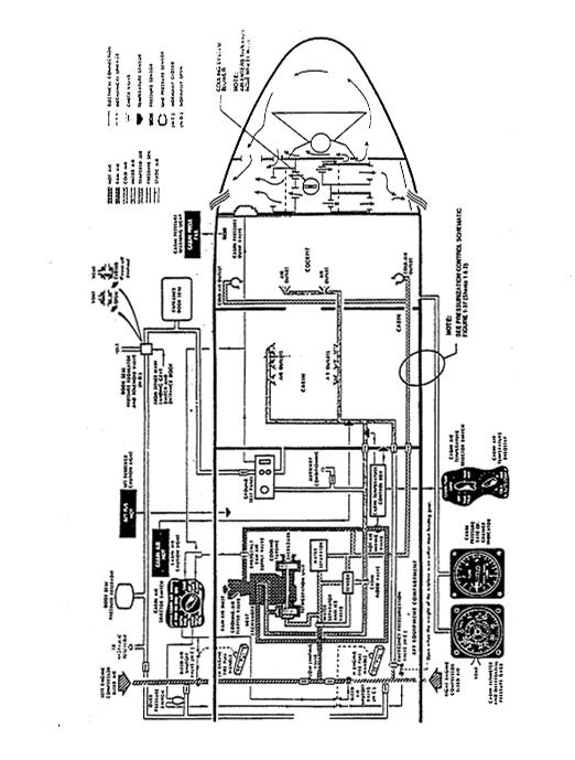
12 C. Engine Fuel Control 1. An engine driven hydromechanical unit, controlled by a mechanical linkage to the throttle, meters fuel to the engine. 2. A mechanical computer receives signals from compressor inlet pressure (PT2), engine RPM, throttle position, and compressor discharge pressure (PT5) to meter fuel to meet required thrust. 3. An engine driven, two element (centrifugal and gear) fuel pump supplies high pressure fuel to the engine. Loss of the gear element of the fuel pump will result in flameout. 4. The centrifugal element has suction feed capabilities to at least 15,000 MSL if a wing tank mounted boost pump fails, regardless of fuel temperature. D. Oil system 1. Lubricates and cools the engine bearings. Engine oil pump is located on the engine accessory gearbox. 2. Fuel/oil cooler maintains normal operating range of C. Temperature is controlled by adjusting fuel flow (via throttles). Primary purpose is to cool the oil. 3. Total capacity is 2.03 U.S. gallons; 1.6 U.S. gallons is full servicing. 4. Normal oil pressure is psi with fluctuations of +5 psi; idle is 35 psi min. 5. OIL PRESS LOW light if the oil pressure falls below 28 psi. Check gauges to determine affected engine then execute OIL PRESSURE (below 35 PSI) EP. E. Ignition 1. Two igniters: Located in the No. 3 and No. 6 burner cans. 2. No. 3 igniter may spark continuously. No. 6 is duty cycle limited: 2 min ON, 3 min OFF 2 min ON, 23 min OFF 3. Red starter button(s) illuminate anytime igniter(s) are providing spark to engine. 4. SWITCH POSITION a. CONTINUOUS: Constant power to the No.3 igniter only. Selected during: (1) T/O (2) LDG, (3) flight in icing conditions, turbulence, or heavy precipitation, or (4) anytime FUEL FILTER BLOCK caution light illuminates. b. NORMAL: Powers BOTH igniters during: (1) engine start (from throttle advancement to idle until 31-35% RPM), (2) with AIRSTART SWITCH in LH or RH position, or (3)during stall warning. 1-2 ENGINES
13 F. Start Sequence 1. ENGINE MASTER switches ON: a. Opens the respective fuel shutoff valve (FUEL SHUTOFF FAIL light while valve in transition). b. Arms igniters to come on with throttle at IDLE. c. Energizes wing mounted centrifugal fuel boost pump. d. Provides DC essential bus power to T/R system. e. Arms hydraulic warning horn. 2. Depress push-pull starter button. Hold until 30% RPM in case the DC voltage is insufficient to hold the solenoid. a. May be pulled out to suspend engine start. b. Pops out at 31-35% rpm with the starter current less than 200 amps to terminate start cycle. NOTE: Starter must be out before generator will work. 3. Throttle to IDLE at 8-10% RPM, ignition is energized. A red light in starter button indicates that ignition is on. 4. Starter/Generator a. Performs as a starter until 31-35% rpm. b. Starter cycle limitation: (1) Four 30-second cycles in a 20 minute period with 2 minutes between cycles. c. Generator will come online at 40% unless the starter button is stuck. 5. Ignition on until 31-35%. 6. Start ABORT criteria: After depressing the starter button: a. 8-10% RPM not attained in 15 seconds b. No oil pressure within 20 seconds After moving the throttle to IDLE c. Fuel flow < 260 or > 600 PPH (hot start) d. No light off within 20 seconds (wet start) e Engine fails to reach IDLE (42% + 1% RPM) within 1 minute (hung start) f. Max tailwind for start is 10 kts. ENGINES 1-3
14 g. On 1 st engine start, EGT, RPM, and fuel flow are available, remaining engine instruments available once generator on line. Oil Pressure is avail on a cart start but not with BATT start. 7. Hot Start Characteristics a. Rapid rise through 475 (not to exceed) or reaching 525. b. Other factors for hot start include initiating start at a low battery state or low rpm c. Fuel flow over 600# per hour resulting in improper fuel-air ratio d. Engine rpm hanging up and failing to accelerate to idle rpm in a normal manner after ignition. 8. AIRSTART switch a. LH ON, RH ON b. Provides ignition to both igniters. c. May have to reset DC generator if engine RPM decays below 40%. d. Airstart switch must be OFF before gen will come on-line. e. Use starter button to assist airstart if rpm < 10-20% instead of AIRSTART switch. f. Airstart envelope - max alt 29,000 ft / min airspeed 160 KIAS (see fig 5-4). G. Bleed Air 1. Fourth-stage interstage bleed valve cycles to preclude compressor instability at low thrust settings. a. This is known as the bleed strap, and it should close above % rpm. If the bleed strap does not close, the resulting possibility is undesirable stress in the compressor section of the engine. 2. High pressure 9th-stage bleed air is for airframes use (pressurization, anti-ice). 3. Bleed air valves controlled by FIRE pull handles and Cabin Air Selector switch. 4. With both engines at the same EPR setting, an interstage bleed valve stuck in the open position above 80% +1 will be indicated by a higher RPM, EGT, and FF. H. Fire and overheat detection 1. Continuous element alarm to detect fire (forward engine pod) or overheat (aft engine pod). 2. Detection of fire or overheat results in red light in the FIRE pull handle and an (loud) alarm bell, accompanied by master caution lights. 3. Limit the fire test to once in any 10 minute period. 1-4 ENGINES
15 4. AFT FUS HOT light at 135 C (battery compartment, hydraulic reservoir, pressurization bleed air ducts). 5. Pulling the FIRE handle: a. Closes respective fuel shutoff valve. b. Places respective DC and AC gen's off line. c. Closes respective engine bleed air valve & emergency bleed air valve for RH engine. d. Positions direction valve (if RH). e. Arms the fire bottle discharge valves. f. Fire bell shutoff. g. Arms the fire extinguisher selector switch. h. Illuminates the fire control panel. i. Deactivates the thrust reverser hydraulic control valve, if the T/R switch is ON. j. Pulling a second Fire Pull Handle will reset everything except the generator, provided the engine master switch has not been moved to OFF.6. One or both bottles may be discharged into either engine. 7. Extinguisher bottle a. Pressure gauge in each wheel well. Preflight check NOT required by crew. b. Two disk indicators on fuselage are below left engine. (1) Yellow - One or both bottles discharged to the engine (2) Red - The fire bottle has been vented overboard due to overheat 8. Fire test - 5 lights will be illuminated and a bell will sound. 2 FIRE pull handle, 2 master caution, AFT FUS HOT I. Thrust reversers 1. Provides deceleration during aborted T/O or during LDG. Decreases rollout by 24%. 2. Separate accumulator: precharged to psi 3. Cockpit light indications (one for each T/R): Yellow ARM, red UNLOCK, blue DEPLOY lights. 4. Switch positions a. OFF: no power. b. ON: power available to T/R if main gear down and locked and throttles are IDLE; WEIGHT ON WHEELS NOT REQUIRED. ENGINES 1-5
16 c. EMERG STOW: Hydraulic pressure directed and maintained to the actuator stow ports; used for T/O and LDG. 5. Operation a. Before landing, determine an EPR setting (if the field elevation > 3000 MSL) or set the lever stops for field temperature. b. Throttles to IDLE at or before touchdown. c. On deck 1-6 ENGINES
17 Figure 1-1. Thrust Reverser Controls and Indicators (un-2-26) ENGINES 1-7
18 UNIT ONE REVIEW QUESTIONS 1. The T-39N/G uses turbojet engines designated. 2. T-39N/G engines are rated at lbs of thrust at sea level. 3. The two stage reaction turbine drives the. 4. The nine stage axial-flow compressor drives the. 5. Fuel flow to the burners is metered by. 6. Starter/generators act as starters until % rpm. 7. Start sequence may be terminated by. 8. Ignition is provided during start by igniters provided the switches are ON and the throttles are at IDLE. 9. The ignition duty cycle is min ON, min OFF min ON, min OFF 10. Start abort criteria: RPM fails to reach 8-10% in seconds Fuel flow outside to lbs/hr EGT rises above C (or rapidly through C) No oil pressure in seconds Fails to reach idle rpm in seconds 11. The use of CONTINUOUS ignition is limited by the ignition duty cycle. (TRUE/FALSE) 12. The primary reference for setting power is the. Providing EGT and RPM are not exceeded. 1-8 ENGINES
19 13. Hot start characteristics are: Battery state Initiating start at rpm. Fuel flow over during initial start will result in an improper fuel-air ratio which will invariably cause a very rapid rise in EGT. hanging up and not accelerating to idle rpm in a normal manner after ignition.(hung start??) 14. Complete the following engine limits: RPM: EGT: Oil: Idle, maximum Idle, max continuous T/O or acceleration Idle psi, normal psi/ ºC 15. The OIL PRESS LOW caution light illuminates when oil pressure falls below PSI. 16. Thrust reverser ARM lights illuminate when, and (provided the engine masters are on) 17. During takeoff and landing, the thrust reverser switch must be placed to. 18. The MASTER CAUTION light will illuminate if either thrust reverser or light comes on in-flight. 19. Pulling a FIRE PULL handle will close the and shutoff valves, take the off the line, arm the, silence the, and position the extinguisher direction valve (if the handle is pulled). 20. Both fire bottles may be discharged into one engine. (TRUE/FALSE) 21. On preflight, the red fire bottle indicator disk is ruptured. This indicates. ENGINES 1-9
20 THIS PAGE INTENTIONALLY LEFT BLANK 1-10 ENGINES
21 UNIT TWO: FUEL SYSTEM REFERENCE: T-39 NATOPS MANUAL ENABLING OBJECTIVE: A.1 Locate and operate T-39 N/G aircraft systems, given a mission in a T-39 in accordance with NATOPS. ENABLING STEP: A.13 Recall the basic description, related systems, and operating limitations of the T-39 fuel system. NATOPS TWO: FUEL SYSTEM A. Fuels 1. Military: JP-4. JP-5. JP-8 2. JET B+, JET A, JET A+ (PRIST not necessary) B. Fuel tank capacities/limitations 1. Fuselage tank (161 gals, 1100#) plus two wing tanks (451 gals each, 6130# total). 2. Total usable fuel of 1063 gals, or 7200# based on JP-5 (6.8#/gal. - standard day). 6900# based on JP-4 (6.5#/gal. - standard day). 3. Max imbalance is 200# during T/O and LDG, 400# en route. 4. Zero fuel weight: T-39N 13,300# (crew & baggage) 11,700# (empty). Max gross weight: T-39N 20,422#, T-39G 20,372#. 5. Max takeoff weight: T-39N 20,037#, T-39G 20,172#. 6. Max landing weight: T-39N 17,500#, T-39G 17,500#. 7. Second segment fuel consideration - minimum climb gradient of 2.4% (24ft /1000ft of downrange travel) at V2 (safe single eng climb speed) to a minimum of 400 feet AGL or obstacle clearance altitude, whichever is higher. (Gear up/flaps up/take-off thrust). Since A/C weight, air temp, and field elevation are the factors for maintaining this minimum climb gradient, fuel weight may have to be reduced to maintain second segment climb. FUEL SYSTEM 2-1
22 C. Fuel transfer (refer to NFM F O - 9 ) 1. Gravity feed from fuselage to wing tanks. 2. Transfer ejector pumps, in wings use motive flow to direct fuel to boost pumps. 3. LH/RH wing mounted centrifugal boost pumps (electrical driven) - Energized when respective Engine Master ON. Provide pressurized (17-30 psi) fuel to engine driven pump. 200# unavailable if a boost pump fails. (400# if both fail) 4. Engine-driven two-element pump (centrifugal boost and gear) delivers high pressure fuel to the engine fuel control. FUEL LOW PRESS light if the pressure difference across the centrifugal pump < 6 psi. 5. Fuel pressurization and dump valve automatically directs fuel to fuel burner manifolds (dump on shutdown). 6. No fuel jettison capability. 7. Normal fuel flow 300# to 3300#/hr. On start fuel flow limits 260# - 600#/hr. D. Fuel shutoff valve 1. Downstream of wing mounted electric boost pumps. 2. Check open when Engine Master ON (FUEL SHUTOFF FAIL light). E. Fuel filter 1. Between centrifugal and gear elements of the engine-driven pump. 2. FUEL FILTER BLOCK light on if differential exceeds 7-8 psi; bypassed if differential exceeds 9-11 psi. F. Fuel heat 1. Use when fuel temp at or below 0 C or with FUEL FILTER BLOCK light on. One minute time limit each 30 minutes (may overheat oil). Do not use during T/O or landing. G. FUEL X-FEED & TANK SEL Switch 1. NORM: Each side is independent: the right wing tank provides fuel for the right engine, and the left wing tank provides fuel for the left engine. Both tank and pump x-feed valves closed, both wing mounted boost pumps ON. 2. LH/RH TANK: Used for normal fuel balancing, select HEAVY tank. Pump x-feed valve opens (but the wing tank x-feed valve stays closed). Boost pump in the wing opposite the selected side is de-energized. 2-2 FUEL SYSTEM
23 3. X-FEED: Used for single-engine or if a boost pump has failed. Both x-feed valves open; both boost pumps ON (even if one Engine Master is off). 4. If balancing is required with X-FEED selected, put the heavy wing high to gravity transfer 100#/minute. H. FUEL LOW PRESS light 1. Either a wing mounted boost pump or the engine driven centrifugal boost pump has failed. If the light stays ON - Engine driven centrifugal boost pump failed; select NORM. If the light goes OUT - Wing mounted boost pump has failed. I. Quantity indicator 1. Two fuel quantity gauges on center instrument panel are primary fuel quantity indicators. 2. Three-position fuel quantity indicator switch located right of pilot s yoke: a. RH IND RH WING/LH IND AUX -RH gauge indicates right wing fuel quantity. LH gauge indicates fuselage (aux) fuel quantity. b. TOTAL-Each gauge indicates half of fuselage and it s respective wing fuel quantity. c. TEST-Causes fuel quantity indicator needles to rotate counter-clockwise to check FUEL LEVEL LOW lights (300#) d. FUEL LEVEL LOW LIGHT is solely a function of gauge reading, not an independent measure. 3. T-39N only - Digital fuel remaining indicators for co-pilot and each student station. Accuracy +80# (advisory indicators only) J. Fueling (Sec 1, part III, Aircraft Servicing) 1. Single point - right wing, inboard, leading edge. (At 50 psi, all tanks fill in 12 mins.) 2. Gravity - port is above right engine; hold wingtip flapper valves (located inside overwing gravity filler ports) open for ventilation. Each wing can also be filled separately through overwing gravity filler ports. FUEL SYSTEM 2-3
24 2-4 FUEL SYSTEM Figure 2-1 Engine Fuel Control System (un 2-20)

25 Figure 2-2 FUEL SYSTEM 2-5
26 UNIT TWO REVIEW QUESTIONS 1. Each wing tank holds gallons and the fuselage tank holds gallons for a total of gallons (approx. lbs JP-5). 2. Gravity fueling is normally accomplished through overwing ports located on the outboard section of each wing. (TRUE/FALSE) 3. The pumps provide fuel pressure to the engine driven pumps. 4. The wing-mounted boost pump is energized whenever the switch is ON. 5. Under most conditions, the FUEL X-FEED & TANK SEL switch is left in the position. 6. The LOW FUEL LEVEL caution fight illuminates at an indicated fuel quantity of lbs or less on either fuel quantity gauge. 7. The fuel filter is downstream of the gear element of the engine driven pump. (TRUE/FALSE) 8. The motive flow for the transfer ejector in the forward section of each wing tank is provided by. 9. Suction feed is reliable to at least feet regardless of fuel temperature. 10. The FUEL FILTER BLOCK caution light will illuminate with a differential of to psi. Actual bypass of the filter occurs at to psi. 11. Allowable fuel imbalance is lbs in level flight or lbs for takeoff and landing. 12. The position of the FUEL X-FEED & TANK SEL switch is used for single engine operation or if the FUEL LOW PRESS fight illuminates. 13. Selecting X-FEED automatically turns on and opens the valve (s). 14. The LOW FUEL LEVEL caution fight operates independently of the fuel quantity gauges. (TRUE/FALSE) 15. The digital fuel remaining indicators operate independently of the fuel quantity gauges. (TRUE/FALSE) 2-6 FUEL SYSTEM
27 16. Normal fuel flow is to lbs/hr. 17. Pressure refueling will fill all tanks in approximately minutes. 18. The or position of the FUEL X-FEED & TANK SEL switch is used for fuel balancing. 19. Selecting LH TANK turns off the and opens the valve (s). 20. The fuel heater is used if fuel temperature is or if the caution light illuminates. 21. Fill in: Boost/Tank x-feed -OPEN or CLOSED LH/RH boost pump- OFF or ON Switch position Boost x-feed Tank x-feed LH boost pump RH boost pump X-FEED NORMAL LH RH FUEL SYSTEM 2-7
28 2-8 FUEL SYSTEM THIS PAGE INTENTIONALLY LEFT BLANK
29 UNIT THREE: ELECTRICAL SYSTEM REFERENCE: T-39 NATOPS MANUAL ENABLING OBJECTIVE: A-1 Locate and operate T-39N/G aircraft systems, given a mission in a T-39 in accordance with NATOPS. ENABLING STEP: A.1.4 Recall the basic description, related systems, and operating limitations of the T-39N/G electrical system. NATOPS THREE: ELECTRICAL SYSTEM A. DC Power sources 1. Two external power receptacles located under left engine inlet. a. Oval utility outlet powers all buses except starter bus. Used for ground maintenance. 28 VDC, 300 amps. b. Rectangular starter outlet. 28 VDC, 800 amps minimum required. Powers starter bus only. (Batteries disconnected from start bus but still powers DC Essential bus.) 2. Batteries (5 batteries total in T-39) a. - Two 26 volt, 40 amp hr, normally in parallel (in series for battery start). - Temp gauges - amber at 120 F, red at 150 F (BATT HOT master caution) - Approx 45 minutes of power avail in the event of dual gen failure. (Battery power only. Secure hydraulic pump in T-39G model and use only if necessary.) b. Two 7.2 volt batteries, each powers half of the emergency lights (30 minutes). c. One Emergency standby attitude gyro battery (4 hours). 3. DC Generators a. Two 28 volt, 400 amp engine-driven starter-generators. (Normal v = ) b. Powers the paralleling bus directly. c. Act as starters during engine start (31-35%) ELECTRICAL SYSTEM 3-1
30 B. DC power distribution (see FO-7 and fig. 1-16). 1. Starter bus - powered by external power or batteries in series. Minimum of 24v before battery start/ 12v during battery start. 2. Battery bus - Can power the paralleling, essential, or start bus. 3. Paralleling bus In flight, powered by generator(s) {will automatically disconnect with a Dual Gen Fail}. On deck, powered by external power, batteries, or generator(s). Can power all buses except the start bus. Powers the hydraulic pump. Remains powered in Dual Gen Fail condition if in T-39G. 4. DC essential bus a. Powered by paralleling bus. b. Powered by batteries if dual gen failure in flight. 5. DC secondary bus a. Energized by the paralleling bus on deck, only if both DC generators are online or external power is applied. b. In flight, powered by paralleling bus with either DC generator online (no power if dual gen failure). 6. T-39N only - DC mission bus A and B (DC MISSION PWR switch) a. Powered by DC essential bus. b. Bus A supplies power to the radar inverters and mission essential equipment. Should bus A overload, the Mission Bus A circuit breaker will trip causing the MISSION A FAIL annunciator light to illuminate. c. Bus B powers cabin non-essential loads. Note: see fig 1-17(sheet 10 of 10 for BUS A/B power distribution) d. Should either generator fail with both buses energized normally, load shed of both A & B buses will occur. Moving the Mission Power Switch to EMER restores power to bus A and radar only. Should both generators fail, load shed of both buses will occur and they will remain shed. C. DC power controls 1. Electrical Master switches: guarded ON, allows the battery switch to function and the generators to power the paralleling bus. 2. Battery switch: a. ON - connects the battery bus to paralleling bus (allows automatic transfer to ESS bus in the event of a dual gen fail; parallel bus taken off line). 3-2 ELECTRICAL SYSTEM
31 b. ESS - manual connection of batteries to essential bus with dual gen fail (only to be selected if auto transfer fails). c. OFF - disconnects battery bus from paralleling bus. 3. DC gen switches: generators online at 40% rpm provided the Electrical Master is ON, Fire Pull handle is in, or the Engine Start (ground or air) is off. Positions are ON-OFF- RESET. 4. DC MISSION PWR switch: a. NORM - power to DC mission bus A and B from essential bus. b. EMER - power to DC mission bus A if single gen failed. c. OFF - removes power from both DC mission bus A and B. 5. Battery isolation switches: a. OVERRIDE - Used during 2nd engine start with battery switch off (allows the battery to start the 2nd engine while the 1st engine generator powers the paralleling bus). b. ISOL - Removes the respective battery from the battery bus via the isolation relay. c. NORM - Normal connection of batteries to battery bus. D. DC power indicators 1. Voltmeter - shows essential bus voltage unless PUSH LH/RH GEN VOLT is depressed. 2. Loadmeter - LH/RH, should be within 1 division (after engine start, up to 30 min allowed to stabilize). Caution lights single DC GEN OFF - reset ( Gen will kick off line btwn 31-33v) LH/RH DC GEN HOT - gen OFF (155 C) BATT HOT - Battery switch off (150 F) ESS BUS CB OUT - extra loads OFF MISSION A or B FAIL - select EMER if the radar is desired. E. Single DC Generator Ops 1. Max load on operating generator =.8 - sea lvl to 30,000'.5-30,000' to 40,000' 2. Maintain.65M for cooling, max op altitude = 40,000 F. AC power source 1. Main or Stdby inverter (1500 or 1250 v-a, volts) 2. Instrument inverter (1000 v-a, volts) ELECTRICAL SYSTEM 3-3
32 3. Six - mission inverters (provides power for mission AC bus) Note: inverters change DC to AC 4. Engine-driven AC generators for forward windshield heat only. G. AC power distribution (FO-8) 1. AC secondary bus: powered by either the main or stby inverter. 2. AC primary bus: powered by AC secondary bus or directly from the instrument inverter if both main and stby fail. 3. Mission AC bus: powered from DC mission bus A (radar bus); AC MISSION PWR switch ON/OFF. 4. #1-26 vac bus powered by AC primary bus (oil/hyd/oxy ind). 5. #2-26 vac bus powered by AC secondary bus (ADF/alt altr). 6. Four 5 vac indirect light busses powered by AC secondary bus. H. AC power controls 1. Inverter switch a. MAIN - essential bus powers main, standby, and instrument inverter, in that order. (automatic fail down mode available) b. STBY - essential bus powers stby inv only; no faildown mode. c. OFF - no ess bus power (no AC power available). d. MAIN INV FAIL light, STBY INV FAIL light. 2. Only instrument inverter available with battery power only. I. AC power indicators 1. AC voltmeter: shows voltage of operating inverter. 2. AC INST PWR OFF light - Total loss of AC power, must be accompanied by MAIN and STBY INV FAIL lights. 3. FT {fault) lights - phase A,B, C (two inverters per phase) - will illuminate if any of the mission inverters in its particular phase fails; loss of two inverter on the same phase will shut down the radar (the only way to tell if two inverters in one phase have failed is that the radar will fail). 3-4 ELECTRICAL SYSTEM
33 Figure 3-1 ELECTRICAL SYSTEM 3-5
34 UNIT THREE REVIEW QUESTIONS 1. External power requirements are: Utility: volts amps Start: volts amps 2. The battery bus is connected to two volt batteries through. 3. The Starter bus is powered either by connected in (series/parallel) or by 4. The Starter bus supplies power to the starter-generators and engine instruments necessary to monitor the start. (TRUE/FALSE) 5. The Paralleling bus is powered by the bus, the or. 6. The DC Essential bus is normally powered by the bus; in the event of a dual generator failure in flight, it receives power directly from the bus. 7. The ESS position of the battery switch should be selected only if. 8. With a single generator failure, Mission DC bus(es) will be shed. Mission bus(es) may be regained by placing the mission bus switch to EMER. (TRUE/FALSE) 9. On deck, with a single generator operating, the Secondary bus will remain unpowered. (TRUE/FALSE) 10. Aircraft AC power is supplied by two volt-amp inverters or one voltamp inverter, which in turn receive DC power from the bus. 11. If both the MAIN and STANDBY inverters fail, AC power is available from the inverter to the bus only. 12. AC power from the MAIN or STANDBY inverters power the AC bus, which in turn powers the bus, one 26 VAC bus and four 5 VAC buses. 13. In the event of a loss of all AC power, the caution light will illuminate. 14. Mission AC inverters are powered by Mission DC bus. (TRUE/FALSE) 3-6 ELECTRICAL SYSTEM
35 15. A TOTAL of three mission inverters (one in each phase)can fail and the radar will still be available. (TRUE/FALSE) 16. Battery temperature should be monitored in flight; if the temperature exceeds 120 F, it will be indicated by. 17. If the battery temperature exceeds F, the battery shall be isolated. 18. If battery temperature exceeds 150 F, the and the caution light will illuminate. 19. Left and right DC loadmeters should show generator output balanced within of each other. 20. If the DC GEN OFF caution light illuminates, check the to determine which generator is not operating. Hold the generator switch at RESET and push the LH/RH GEN VOLT buttons while checking the. 21. With a single generator failure in flight, the loadmeter for the operating generator should be below a maximum of (sea level to 30,000 ft) (30,000 to 40,000 ft) ELECTRICAL SYSTEM 3-7
36 THIS PAGE INTENTIONALLY LEFT BLANK 3-8 ELECTRICAL SYSTEM
37 UNIT FOUR: HYDRAULIC SYSTEMS REFERENCE: T-39 NATOPS MANUAL ENABLING OBJECTIVE: A-1. Locate and operate T-39N/G aircraft systems, given a mission in a T-39 in accordance with NATOPS. ENABLING STEP: A.1.5. Recall the basic descriptions, related and operating limitations of the T-39N/G hydraulic systems. NATOPS FOUR: HYDRAULIC SYSTEMS A. Main hydraulic system (3,000 psi system) 1. Components: a. Electric motor driven pump (paralleling bus) b. Hydraulic reservoir (2 gal.) c. Accumulator ( psi nitrogen pre-charge) d. Hydraulic pump switch e. Cockpit-pressure gauge ( psi) 2. Operates landing gear, main gear doors, speedbrake, wheelbrakes/anti-skid, thrust reversers and NWS. B. Controls and indicators 1. Switch positions a. MANUAL - pump runs continuously; 1 minute time limit. Spring-loaded to AUTO. b. AUTO - pump ON when pressure < 2700 psi until pressure returns to 3000 psi. c. OFF&RESET - OFF position/resets power if tripped by overtime or overcurrent. 2. HYD PRESS PWR OFF LIGHT a. Pressure < 2700 for more than 1 minute. b. Switch is in OFF&RESET position. c. Pump CB out (2A3 & 2A4). HYDRAULIC SYSTEMS 4-1
38 d. Over temp. e. Over time (pump on longer than 1 minute). f. Over current. g. Pressure < psi. Only time that the master caution light does not come on with an annunciator light. Will see in connection w/ speedbrake operation. 3. Hydraulic fail audible warning (on deck ONLY) a. Weight on wheels and either Engine Master ON. b. Pressure < psi (Horn off when > psi). c. Pump switch OFF&RESET. d. Pump CB out. C. Aux hydraulic system 1. Pressure psi (aux accumulator nitrogen pre-charge). 2. Powers speedbrake, wheelbrakes/anti-skid and NWS. 3. AUX SYS switch - select ON just before hydraulics are needed if main system fails. (allows stored pressure fluid to be used from aux accumulator) 4. Hydraulic pressure will bleed down with each actuation of speedbrakes, wheelbrakes, and nosewheel steering. 5. Recommend turning anti-skid OFF prior to landing. Recommend not using speedbrake. D. Landing gear 1. Electrically controlled, hydraulically actuated a. Steady-red light in handle when one or more gear do not correspond to gear handle position. b. Flashing red light in handle when gear is not down & locked and the conditions in paragraph D.5 are met KIAS & 0-2g = operating limits 3. Landing gear override button a. Allows gear handle to be raised with weight on wheels and hyd./elec. power available. (Normally, weight on wheels sensing switch prevents gear handle from being raised with weight on wheels). b. Can be used on a single eng climb after take-off with a faulty weight on wheels switch. 4. Emergency T-handle allows gear to freefall. Do not roll out over arresting gear because main gear doors will be open. 4-2 HYDRAULIC SYSTEMS
39 5. Gear warning horn - flashing red light in handle if a. Airspeed < 140 KIAS (+ 10). b. Either engine < 95%. c. Altitude < (+600 ) MSL (horn can be silenced with the above parameters). d. Any time flaps are beyond 80%; horn CANNOT be silenced. 6. Landing gear downlock and reset button. Resets gear sequencing after emergency gear extension. (allows for normal raising of gear) E. Nosewheel steering 1. Electrically controlled by button on yoke (main only); hydraulically actuated with either hydraulic system. 2. Rudder pedals steer +/- 45 degrees. 3. Either MAIN or STDBY steering - center pedestal a. In MAIN, auto transfer to STDBY if MAIN fails. b. In STDBY, yoke button inop; MAIN STEER FAIL light. c. Free castering after a standby failure can only be accomplished by selecting MAIN. d. Never land with STDBY selected because nose wheel will be canted with rudder movement. e. NOSE STEER TRAIL light if main/stdby failed (use differential braking). f. NWS light on if either main/stdby engaged. 4. Towing aircraft: close main cabin door, disconnect cannon plug in nose, engage gustlock, turn anti-skid OFF. F. Wheelbrake system 1. Receives pressure from main/aux or emergency brake system. 2. Pressure is metered down to 1800 psi (from main or aux). 3. Emergency brake T-handle operates brakes through independent hydraulic lines. 4. Use aux hydraulics or emer brakes only to clear the runway (tow back to line). 5. Anti-skid a. Inoperative below 10 kts. b. Not available using emer brakes. c. Powered by main or aux hyd (not recommended in aux). d. ANTI-SKID BRAKE FAIL, light. HYDRAULIC SYSTEMS 4-3
40 G. Speedbrake 1. Electrically controlled. Hydraulically actuated. 2. Switch on left throttle. 3. Single panel on bottom of A/C. 4. No airspeed limit; 3g-max. 5. DUMP switch - if hydraulics fail and speedbrake switch OFF, will relieve pressure holding the brake out and allow it to trail. Can be reset for normal operation. 6. Do not roll over arresting gear with SB out ( DUMP switch in DUMP position). 7. Speedbrake does have intermediate positions. 8. SPEEDBRAKE OPEN light if either throttle > 95% rpm; speedbrake will NOT close automatically with throttle advancement. H. Thrust reverser review (Thrust reverser accumulator psi) 4-4 HYDRAULIC SYSTEMS

41 Figure 4-1 HYDRAULIC SYSTEMS 4-5
42 UNIT FOUR REVIEW QUESTIONS 1. The hydraulic reservoir is filled to gallons. 2. The HYD PRESS PWR OFF caution light will illuminate if the fluid pressure drops below psi or is below psi for more than one minute. 3. Hydraulic pressure is provided by positive displacement engine driven pumps mounted on each accessory gearbox. (TRUE/FALSE) 4. The landing gear is controlled and actuated. 5. During normal gear extension, a red light in the gear handle flashes to indicate one or more gear not down and locked. (TRUE/FALSE) 6. The pilot/copilot headset gear warning signal will sound if Either throttle below % rpm Airspeed below KIAS Altitude below MSL and the landing gear is not down and locked. It can/cannot be silenced by the horn cutout button. 7. The gear warning horn will sound if the gears are not down and locked and the flaps. It can/cannot be silenced by the horn cutout button. 8. A full nitrogen service is psi for normal and auxiliary accumulators and psi for the thrust reverser accumulator. 9. The emergency brake system is totally independent of the aircraft main hydraulic system. (TRUE/FALSE) 10. Brake system pressure is psi maximum. 11. Normal hydraulic system pressure is to psi. 12. Auxiliary hydraulic system pressure is to psi. 13. The auxiliary accumulator can supply hydraulic power to, and. 14. Fill in the limitations: Landing gear KIAS to G Speedbrake KIAS to G 4-6 HYDRAULIC SYSTEMS
43 15. Anti-skid brakes are available above knots. 16. If landing with auxillary hydraulic pressure, the anti-skid brake switch should be. 17. If landing with auxillary hydraulic pressure, the thrust reversers will be inoperative. (TRUE/FALSE). 18. Optimum performance from anti-skid brakes is obtained by applying and holding MAXIMUM pressure. (TRUE/FALSE) 19. In the event the speedbrake fails to retract normally, it can be retracted using. 20. The SPEEDBRAKE OPEN caution light illuminates if either throttle is above 95% and the speedbrake is not retracted. (TRUE/FALSE) 21. For gear extension, the steady red light in the gear handle will remain illuminated until all three wheels are down and locked and the inner gear doors are up and locked. (TRUE/FALSE) 22. Hydraulic power is available with DC essential power. (TRUE/FALSE) HYDRAULIC SYSTEMS 4-7
44 THIS PAGE INTENTIONALLY LEFT BLANK 4-8 HYDRAULIC SYSTEMS
45 UNIT FIVE: FLIGHT CONTROLS REFERENCE: T-39 NATOPS MANUAL ENABLING OBJECTIVE: A.1 Locate and operate T-39N/G aircraft systems, given a mission in a T-39 in accordance with NATOPS. ENABLING STEP: A.1.6 Recall the basic description, related and operating limitations of the T-39N/G flight control systems. NATOPS FIVE: FLIGHT CONTROLS A. Mechanical elevators, ailerons, rudder. B. Trim 1. Gustlock - locks the elevators, ailerons, and rudder. Will also prevent throttle advancement beyond idle. 1. Pitch (horizontal stabilizer), roll (tab on left aileron), yaw (rudder tab). 2. Controlled by 3-position switch below pilot instrument panel: a. NORM: 5-position switch on pilot/co-pilot yoke, controls NORMAL pitch/roll trim, switch on center pedestal controls rudder trim. b. OFF: No trim available. c. ALT: Trim using alternate trim switches in front of pilot s right knee; used for runaway trim condition or if normal system fails. 3. Trim indicators on center instrument panel. NORMAL T/O setting: 0 (aileron), 4 UP (elevator), 0 (rudder). 4. Autopilot will trim for roll or yaw with switch in NORM, ALT, or OFF. Can only trim in pitch if NORM (ALT HOLD). 5. A/P TRIM FAIL light ON if trim attempted with autopilot coupled. C. Flaps 1. Electrically controlled and actuated (two actuators). 2. Flaps interconnected by a flexible shaft. FLIGHT CONTROLS 5-1
46 3. Movement is available at a reduced rate if one actuator fails. 4. Handle on center pedestal a. UP - for T/O and after touchdown to increase weight on wheels for brake effectiveness. b. HOLD - allows for intermediate positions; approach flaps = 66%. c. DOWN - 25 degrees; 180 KIAS max; 0-2g. 5. Flap position indicator on center instrument panel. 6. Recommended no flap landing for x-wind > 25 kts. 7. Increase V ref by 10 kts for no flaps landing (same as single eng.) D. Slats 1. Operate as a function of airspeed and AOA. 2. Begin to open as aircraft decelerates through 180 KIAS. 3. Increase V ref by 15 kts if stuck slat. E. Stall warning 1. Stick shakers at 24 units AOA. 2. Stall warning transducers under center of right wing, just behind leading edge. 3. Operate - Below 16000: 107% of STALL speed Above 42000: 110% of FLAMEOUT (180) 16K - 42K: whichever is higher 4. Automatic power to both igniters (starter button lights-starter duty cycle applies). F. Prohibited maneuvers 1. Pitch greater than 60 degrees up or down. 2. Lateral deflections > 1/2 throw above 300 KIAS (225KIAS if 2 adjacent or more than 3 total vortex generators are missing). 3. Spins. 4. Operation in stall warning buffet ABOVE 25K. 5. Yaw maneuvers in other than lg flight. 5-2 FLIGHT CONTROLS
47 UNIT FIVE REVIEW QUESTIONS 1. Normal trimming is accomplished by use of the trim select and normal trim switches, colocated on the pilot s trim control panel. (TRUE/FALSE). 2. Flap limitations are KIAS and G s. 3. No flap landings are recommended for crosswinds in excess of knots. In any case a no flap landing requires that V ref be increased by knots. 4. With an inoperative or stuck slat, V ref should be increased by knots. 5. Activation of the stall warning system provides electrical power to the continuous or #3 igniter only. (TRUE/FALSE). 6. List the five prohibited maneuvers in the T-39: a. b. c. d. e. FLIGHT CONTROLS 5-3
48 THIS PAGE INTENTIONALLY LEFT BLANK 5-4 FLIGHT CONTROLS
49 UNIT SIX: ANTI-ICE/DE-ICE SYSTEMS REFERENCE: T-39 NATOPS MANUAL ENABLING OBJECTIVE: A.1 Locate and operate T-39N/G aircraft systems, given a mission in a T-39 in accordance with NATOPS. ENABLING STEP: A.1.7 Recall the basic description, related systems, and operating limitations of the T-39N/G anti-ice/de-ice system. NATOPS SIX: ANTI-ICE/DE-ICE SYSTEMS A. Activate anti-ice system when OAT is +5 to - 20C and in visible moisture. B. Sources of anti-ice 1. Engine compressor bleed air (9th stage) is provided to the following: a. Engine inlet duct. b. Engine flow straightener vanes. c. Engine guide vanes. d. Engine nose bullet. 2. Electrical heat is provided to the following: a. Pitot tubes. b. Stall warning vanes. c. EPR probes. d. Ram air inlet. e. AOA probe. f. Windshield. g. AC and DC generator inlets. ANTI-ICE/DE-ICE SYSTEMS 6-1
50 C. Anti-ice controls 1. ENGINE & RAM AIR INLET switch. a. Opens each engine s ANTI-ICE SHUTOFF VALVE, providing bleed air to each engine. (ENG inlet, flow straighteners, inlet guide vanes, and bullet nose). With a TOTAL electrical failure, only inlet guide vanes and bullet nose will be anti-iced. b. Provides electric heat to AC/DC generator inlets and ram air inlet on vertical tail. c. If either forward windshield heater is inop, and window is unheated, do not exceed 250 KIAS below 10,000. D. De-icing system 1. Removes accumulated ice on: a. the wing slats b. under slat surfaces and leading edge of wing roots c. vertical and horizontal tail leading edges. 2. Electrically controlled, pneumatically operated with engine bleed air. 3. Automatic operation - PNEU BOOTS LT/HVY/OFF switch. a. Each set-of boots (wing, slat, empennage) is pressurized for 5 seconds, with a dwell time of 45 seconds (HVY) or 165 seconds (LT). b. WING/SLATS/EMP lights will be on. c. Automatic operation is powered by DC SECONDARY BUS. d. Can be inflated on deck to check operation. 4. Manual operation - depress each WING/SLATS/EMP light for 5 seconds, repeating as necessary. a. Manual operation is powered by DC ESSENTIAL BUS. 5. For most effective operation, use pneumatic boots when ice thickness reaches 1/4 inch. 6. For de-icing operations (pneumatic boots) engine RPM must be > 75%. 7. Ice check lights 6-2 ANTI-ICE/DE-ICE SYSTEMS
51 E. Fuel Heater 1. Used when FUEL FILTER BLOCK light illuminates (possible ice crystals) or when fuel temperature drops below 0 C to warm fuel filter. Fuel heater is in the engine fuel pump, upstream of the fuel filter, NOT in fuel tank (fuel temp probe in left fuel tank). 2. One minute time limit for every 30 minutes to prevent oil overheat. 3. NOT to be used on takeoff or landings. F. With engine anti-ice systems on, use appropriate charts for computing Max continuous, climb, Cruise, and Reverse thrust EPR values. Reduce Wave Off EPR by 10, per the chart notes. Figure 6-1 Airframe Anti-Icing Systems (un-119) ANTI-ICE/DE-ICE SYSTEMS 6-3
52 Figure ANTI-ICE/DE-ICE SYSTEMS
53 UNIT SIX REVIEW QUESTIONS 1. Anti-icing systems shall be turned on when operating in with a temperature range of to C. 2. A minimum of EPR is required to operate the engine anti-ice system. 3. The engine ignition switch should be placed in NORMAL when the anti-ice systems are turned on. (TRUE/FALSE) 4. Placing - the ENGINE & RAM AIR INLETS switch ON opens the bleed air shut-off valves for engine anti-icing and provides power to electrically heat the and. 5. With weight off the wheels, electrical anti-icing is, automatically provided to the and. 6. The stall warning vanes will be heated in flight as long as power is available to the bus. (TRUE/FALSE) 7. The AOA heater will operate in flight with only one generator on line. (TRUE/FALSE) 8. Electrical power to anti-ice and bird proof the forward windshields is controlled by the switches and the switch. 9. The SIDE WINDSHIELD switch sends DC secondary bus power to heat the and and both. 10. The temperature of all heated windows except the is monitored for the WINDSHIELD HOT caution light. 11. While taxiing for takeoff, you get a LH AC GEN OFF caution light. No corrective action is necessary, since output is limited below 58% rpm. (TRUE/FALSE) 12. If either windscreen is unheated, airspeed is limited to KIAS below feet. 13. The airfoil de-icing system is designed to be used BEFORE ice has accumulated on the leading edges of the wing and empennage. (TRUE/FALSE) 14. When the PNEU BOOTS switch is selected to HVY, the dwell time between boot inflation is seconds. 15. Operation of the de-icing system can be monitored by. 16. If manual inflation of the de-ice boots is desired, it can be accomplished by. ANTI-ICE/DE-ICE SYSTEMS 6-5
54 17. Best use of the de-ice boots is achieved when the ice reaches a thickness of inch (es). 18. In the event of dual generator failure, the de-ice boots will function, but only in the automatic mode. (TRUE/FALSE) 19. When the PNEU BOOTS switch is selected to LT it is possible that boot in occur for up to sec s. 6-6 ANTI-ICE/DE-ICE SYSTEMS
55 UNIT SEVEN: ENVIRONMENTAL SYSTEMS REFERENCE: T-39 NATOPS MANUAL ENABLING OBJECTIVE: A.1 Locate and operate T-39N/G aircraft systems, given a mission in a T-39 in accordance with NATOPS. ENABLING STEP: A.1.8 Recall the basic description, related systems, and operating limitations of the T-39N/G environmental systems. NATOPS SEVEN: ENVIRONMENTAL SYSTEMS A. Air conditioning (primary cooling system) 1. 9th stage bleed air duct is split into three branches, cooled, hot, and door press. a. Cooled, through heat exchanger (cooled by ram air), then through expansion turbine. b. Mixing valve controlled by rheostat or toggle (to regulate temp). c. Anti-icing valve to prevent icing in water separator (keeps conditioned air above 0 C). 2. Bleed air shutoff valve on each engine stops airflow if leak is suspected (CABIN AIR SELECT switch) 3. Either engine can provide full system capability. 4. Aux air conditioner - main purpose is ground cooling and augments primary system. a. MODE switch - air conditioner or circulation. b. FWD EVAP/AFT EVAP - cockpit/cabin evaporators. c. Should be OFF by 10K; shall be secured at FL 180 (due to compressor motor arcing). d. Powered by Mission bus B (lost if single gen). e. Uses Freon, NOT bleed air. B. Pressurization 1. Cabin pressure regulator controls pressurization. a. Pressure regulator inop from SL to 8000 MSL (unpressurized). b. Regulator maintains 8000 cabin altitude above the 8000 pressure altitude to a maximum of 8.8 cabin pressure differential. ENVIRONMENTAL SYSTEMS 7-1
56 c. Aircraft ceiling is 45,000 MSL. 2. Dump valve prevents cabin pressure from exceeding above outside pressure. 3. Cabin pressure dumps with weight on wheels. 4. AFT FUS HOT light if bleed air leak (135C). -select RAM below 15K -select EMER PRESS above 15K 5. CABIN AIR HOT light on if air downstream of mixing valve exceeds 130C - select MAN COLD NOTE: Expect this light if EMER PRESS is selected 6. Door seal will remain pressurized with dual gen fail (DC Essential power available); cabin pressure will dump if TOTAL electrical failure. 7. Emergency pressurization from unconditioned RH bleed air; INOP ON DECK or if RH FIRE handle pulled. Control air temperature with throttle position. 8. CABIN AIR SELECT switch controls bleed air valves a. OFF - closes both shutoff valves. b. BOTH ENG - Both bleed air shutoff valves open (normal position). c. LH/RH ENG - single engine operations or contamination suspected. d. RAM - closes both shutoff valves and opens ram air supply valve. e. AM AND DUMP - same as RAM but dumps cabin pressure as well. f. EMER PRESS - closes both shutoff valves and opens the emergency valve from RH engine. NOTE: In RAM or OFF, pressure will bleed off; RAM/DUMP = immediate depressurization. 9. CABIN TEMP switch/ AUTO CONTROL rheostat a. OFF/AUTO/MAN HOT/MAN COLD (spring-loaded to OFF from MAN HOT or MAN COLD). b. Rheostat only operative if BOTH or LH/RH ENG is selected on CABIN AIR SELECT switch. c. Auto temp range of 60-80F 10. CABIN PRESS FAIL red light if cabin altitude exceeds 10, feet. Will also get a FASTEN SEAT BELT light. 7-2 ENVIRONMENTAL SYSTEMS
57 11. The following warnings occur at 13, : a. DON OXYGEN MASK light on. b. NO SMOKING light on. c. Oxygen warning horn on. C. Oxygen system 1. Two 77.9 cubic-foot oxygen cylinders located in cabin. (Aircraft specific) a. Check ON during preflight (normally safety wired ON). b. Normal servicing psi. c. Green blowout disk aft of entry door if pressure exceeds psi. d. All occupants shall use oxygen above FL 410. e. Pilot/Copilot have oxygen available at all times provided the oxygen cylinders are ON and masks are plugged in (no electrical power needed). For other stations, switch on oxygen control panel must be in MAN or AUTO. 2. Oxygen regulators a. Masks at each station. b. Diluter-demand regulators c. EMER/100%/NORM. d. Flow indicators (green/orange band). Green = Oxygen available. * In the event oxygen masks are donned: (1) Deselect VOX mic (use intercom button/toggle to talk). (2) Select OXY mask vice BOOM (for mic). (3) Front seats select Speaker (back seats do not have this available, speakers in cabin are for intercom P.A. system) 3. Passenger Oxygen control panel (pilot s LH console) a. Oxygen pressure gauge ( psi). b. Oxygen warning horn cutout button. c. PASSENGER OXYGEN ON red light (press to test) will be on whenever oxygen is available in cabin. d. OFF -no flow MANUAL - continuous flow AUTO - normal position allowing flow if cabin altitude exceeds 13, MSL. 4. Walkaround bottle located behind co-pilot seat. ENVIRONMENTAL SYSTEMS 7-3
58 7-4 ENVIRONMENTAL SYSTEMS
Bombardier Challenger Auxiliary Power Unit
 GENERAL A Honeywell 36 150(CL) constant-speed gas turbine auxiliary power unit (APU) is installed within a fire-resistant compartment in the aft equipment bay. The APU drives a generator, providing AC
EMERGENCY GEAR DOWN HANDLE CHECK VALVE GEAR DROP TO EXTEND POSITION DOOR SELECTOR DOOR SELECTOR VALVE UPLOCK RELEASE CYLINDER DOOR CYLINDER
 WARN HORN CUT BEECHJET Landing Gear System LEGEND VENT LINE PRESSURE LINE RETURN LINE NITROGEN ELECTRICAL CIRCUIT CABLE LINE PACKAGE DUMP LANDING SELECTOR CHECK SELECTOR EMERGENCY DOWN HANDLE DROP TO EXTEND
Elmendorf Aero Club Aircraft Test
 DO NOT WRITE ON THIS TEST JAN 2014 Elmendorf Aero Club Aircraft Test SENECA II For the following questions, you will need to refer to the Pilots Information Manual for the PA-34-200T. USE ANSWER SHEET
King Air B90. Speeds (KIAS)
") King Air B90 Speeds (KIAS) V MCA 92 V SSE (101) Derived from C90 V X 101 V Y 114 Down to 103 @ 30 000 V XSE 101 V YSE 110 Down to 101 @ 24 000 V A 169 V R 92 V 1 101 V MO 208 V FE 174 35% 130 100% V LE
King Air B90 Speeds (KIAS) V MCA 92 V SSE (101) Derived from C90 V X 101 V Y 114 Down to 103 @ 30 000 V XSE 101 V YSE 110 Down to 101 @ 24 000 V A 169 V R 92 V 1 101 V MO 208 V FE 174 35% 130 100% V LE
The Straight Word. Cessna 208 Caravan 208 Caravan I & 208B Grand Caravan Series
 The Straight Word Cessna 208 Caravan 208 Caravan I & 208B Grand Caravan Series I. FLIGHT PROCEDURES: COCKPIT PREPARATION Fuel Tank Selectors Ignition Switch Heading Bug HSI Course Indicator Altimeters
Cessna Citation XLS - Electrical
 GENERAL Electrical power for the Citation XLS comes primarily from DC sources originating with the starter/ generators, the Auxiliary Power Unit (APU) or the battery. A receptacle below the left engine
Dash8 - Q400 - Pneumatics
 12.19.1 Introduction The Auxiliary Power Unit (APU) replaces the standard composite tailcone with a titanium tailcone and firewall. The APU is accessed by two clamshell type doors on the bottom of the
A310 MEMORY ITEMS Last Updated: 20th th October 2011
 A310 MEMORY ITEMS Last Updated: 20th th October 2011 1. Emergency Descent: Crew Oxygen Mask ON Crew Communication (Headsets) Establish Turn Initiate Descent Initiate o It is recommended to descend with
Vso 61. Vs1 63. Vr 70. Vx 76. Vxse 78. Vy 89. Vyse. 89 (blue line) Vmc. 61 (radial redline) Vsse 76. Va 134) Vno 163
 Vmc. 61 (radial redline) Vsse 76. Va 134) Vno 163") PA34-200T Piper Seneca II Normal procedures V-speeds Knots Vso 6 Vs 63 Vr 70 Vx 76 Vxse 78 Vy 89 Vyse Vmc 89 (blue line) 6 (radial redline) Vsse 76 Va 2-36(@4507lbs 34) Vno 63 Vfe 38 (0*)/2(25*)/07(40*)
PA34-200T Piper Seneca II Normal procedures V-speeds Knots Vso 6 Vs 63 Vr 70 Vx 76 Vxse 78 Vy 89 Vyse Vmc 89 (blue line) 6 (radial redline) Vsse 76 Va 2-36(@4507lbs 34) Vno 63 Vfe 38 (0*)/2(25*)/07(40*)
INDEX. Preflight Inspection Pages 2-4. Start Up.. Page 5. Take Off. Page 6. Approach to Landing. Pages 7-8. Emergency Procedures..
 INDEX Preflight Inspection Pages 2-4 Start Up.. Page 5 Take Off. Page 6 Approach to Landing. Pages 7-8 Emergency Procedures.. Page 9 Engine Failure Pages 10-13 Propeller Governor Failure Page 14 Fire.
REFERENCE: 2861 wings 2044 trunk 4904 total BEW 10,655 BOW 11,185 Max Useful load 5115 MLanding ZFW FUEL BURNS 11min min min
 REFERENCE: 2861 wings 2044 trunk 4904 total BEW 10,655 BOW 11,185 Max Useful load 5115 MLanding 15700 ZFW 13000 FUEL BURNS 11min 357 27min 730 36 min 940 58min 1453 1:17 1800 2:20 2933 2:46 3283 3:00 3600
Canadair Regional Jet 100/200 - Auxiliary Power Unit
 1. INTRODUCTION The auxiliary power unit (APU) is installed within a fireproof titanium enclosure in the aft equipment compartment. The APU is a fully automated gas turbine power plant which drives an
CARENADO COPYRIGHTS. Normal & Emergency Checklist
 NORMAL PROCEDURES CHECKLIST PREFLIGHT CHECK Control wheel -- RELEASE BELTS Avionics -- OFF Master Switch -- ON Fuel quantity gauges -- CHECK Master switch -- OFF Ignition -- OFF Exterior -- CHECK FOR DAMAGE
B737 NG Anti Ice & Rain
 B737 NG Anti Ice & Rain Introduction Thermal anti-icing (TAI), electrical anti-icing, and windshield wipers are the systems provided for ice and rain protection. The anti-ice and rain systems include:
DO NOT WRITE ON THIS TEST FEB 2013 Elmendorf Aero Club Aircraft Test. Cessna - 182
 DO NOT WRITE ON THIS TEST FEB 2013 Elmendorf Aero Club Aircraft Test Cessna - 182 For the following questions, you will need to refer to the Pilots Information Manual for the C-182R. The bonus questions
Bombardier Global Express - Hydraulics
 INTRODUCTION Hydraulic power is provided by three independent and isolated systems designated 1, 2 and 3 and operate at a nominal pressure of psi. SYSTEM 1 AND 2 Systems 1 and 2 are each powered by an
Elmendorf Aero Club Aircraft Test
 DO NOT WRITE ON THIS TEST FEB 2014 Elmendorf Aero Club Aircraft Test Cessna - 185 For the following questions, you will need to refer to the Pilots Information Manual for the C-185F and Graphic Engine
Introduction. APU Location
 B737 NG APU Introduction The auxiliary power unit (APU) is a self contained gas turbine engine installed within a fireproof compartment located in the tail of the airplane. The APU supplies bleed air for
FLIGHT CONTROLS SYSTEM
 FLIGHT CONTROLS SYSTEM DESCRIPTION Primary flight control of the aircraft is provided by aileron, elevator and rudder control surfaces. The elevator and rudder control surfaces are mechanically operated.
24 ELECTRICAL DC ELECTRICAL SYSTEM DESCRIPTION
 24 ELECTRICAL DC ELECTRICAL SYSTEM DESCRIPTION The Direct Current electrical system provides power to most equipment through an electrical bus system. The power may be supplied from one of three sources:
canadair chsfflencjibr
 canadair chsfflencjibr HYDRAULICS TABLE OF CONTENTS Page GENERAL 1 HYDRAULIC SYSTEM COMPONENTS 1 A. Engine Pumps (2) 1 B. Electric Pumps (4) 1 C. Reservoirs (3) 2 D. Accumulators (3) 2 E. Heat Exchanger
CESSNA CITATION C750 (CITATION X) PUNTA BRAVA S.A. (Rev Abril 2012)
 PUNTA BRAVA S.A. (Rev Abril 2012)") DEPARTAMENTO SEGURIDAD OPERACIONAL SUBDEPARTAMENTO LICENCIAS SECCIÓN EVALUACIONES CESSNA CITATION C750 (CITATION X) PUNTA BRAVA S.A. (Rev. 2-10 Abril 2012) A.- LIMITATIONS: 1.- Limitations ( KIAS) V (Turbulence
DEPARTAMENTO SEGURIDAD OPERACIONAL SUBDEPARTAMENTO LICENCIAS SECCIÓN EVALUACIONES CESSNA CITATION C750 (CITATION X) PUNTA BRAVA S.A. (Rev. 2-10 Abril 2012) A.- LIMITATIONS: 1.- Limitations ( KIAS) V (Turbulence
Examen Teórico sobre Habilitación de Tipo B (Última actualización: Septiembre 2016)
") DIRECCIÓN GENERAL DE AERONÁUTICA CIVIL DEPARTAMENTO SEGURIDAD OPERACIONAL SUBDEPARTAMENTO LICENCIAS Examen Teórico sobre Habilitación de Tipo B-737-300 (Última actualización: Septiembre 2016) Materia:
DIRECCIÓN GENERAL DE AERONÁUTICA CIVIL DEPARTAMENTO SEGURIDAD OPERACIONAL SUBDEPARTAMENTO LICENCIAS Examen Teórico sobre Habilitación de Tipo B-737-300 (Última actualización: Septiembre 2016) Materia:
Pneumatic Air Conditioning System Citation, Citation I
 Pneumatic Air Conditioning System Citation, Citation I COCKPIT VENT FOOT WARMER OVERHEAD COCKPIT WINDSHIELD WEMAC OPTIMAL VENT OVERHEAD CONDITIONED AIR DUCTS BLOWER SIDE WINDOW UNDER FLOOR CONDITIONED
Central Warning Systems
 CIRRUS AIRPLANE MAINTENANCE MANUAL Central Warning Systems CHAPTER 31-50: CENTRAL WARNING SYSTEMS GENERAL 31-50: CENTRAL WARNING SYSTEMS 1. General This section describes the Indicating/Recording Systems
GIV MEMORY FLASH CARDS OCT09
 OCT09 GIV MEMORY FLASH CARDS Copyright 2009, FlightSafety International, Inc. Unauthorized reproduction or distribution is prohibited. All rights reserved. INSERT LATEST REVISED CARDS, DESTROY SUPERSEDED
CESSNA 182 CHECKLIST. LEFT WING Trailing Edge 1. Aileron CHECK freedom of movement and security
 CESSNA 182 CHECKLIST PRE-FLIGHT INSPECTION CABIN 1. Pilot s Operating Handbook AVAILABLE IN THE AIRPLANE (A.R.R.O.W.E) 2. Landing Gear Lever DOWN 3. Control Wheel Lock REMOVE 4. Ignition Switch OFF 5.
Landing Gear & Brakes
 EMBRAER 135/145 Landing Gear & Brakes GENERAL The EMB-145 landing gear incorporates braking and steering capabilities. The extension/retraction, steering and braking functions are hydraulically assisted,
GENERAL The Honeywell model TFE731-40AR turbofan engine is a lightweight, two-spool, geared-stage, front-fan, jet engine.
 ENGINE GENERAL The Honeywell model TFE731-40AR turbofan engine is a lightweight, two-spool, geared-stage, front-fan, jet engine. The cross section of the engine is shown in Figure 7-71-1, page VII-71-3.
DCS L-39 ALBATROS REAL PILOT START-UP, TAXI AND TAKEOFF CHECKLISTS V 1.0 PREPARED BY LINO_GERMANY
 DCS L-39 ALBATROS REAL PILOT START-UP, TAXI AND TAKEOFF CHECKLISTS V 1.0 PREPARED BY LINO_GERMANY T.O. 1T-L39C-1.0 P1 INTRODUCTIONS A. CHECKLISTS This compilation contains amplified normal and (hopefully
Elmendorf Aero Club Aircraft Test
 DO NOT WRITE ON THIS TEST FEB 2013 Elmendorf Aero Club Aircraft Test Cessna - 182 For the following questions, you will need to refer to the Pilots Information Manual for the C-182R. The bonus questions
Jump to Table of Contents
 Jump to Table of Contents PIPER AIRCRAFT CORPORATION PA-28R-201, CHEROKEE ARROW III SECTION 3 EMERGENCY PROCEDURES 3.3 EMERGENCY PROCEDURES CHECK LIST ENGINE FIRE DURING
CHAPTER ICE AND RAIN PROTECTION SYSTEM
 15--00--1 ICE AND RAIN PROTECTION SYSTEM Table of Contents REV 3, May 03/05 CHAPTER 15 --- ICE AND RAIN PROTECTION SYSTEM Page TABLE OF CONTENTS 15-00 Table of Contents 15--00--1 INTRODUCTION 15-10 Introduction
CHAPTER 14 LANDING GEAR
 CHAPTER 14 LANDING GEAR Page TABLE OF CONTENTS 14-00-01/02 DESCRIPTION General 14-10-01 Description 14-10-01 Controls and Indicators 14-10-04 COMPONENTS Nose Gear 14-20-01 Main and Center Gear 14-20-02
SECTION 3 EMERGENCY PROCEDURES CONTENTS
 CONTENTS Page Definitions.................................. 3-1 Power Failure - General......................... 3-1 Power Failure Above 500 feet AGL................ 3-2 Power Failure Between 8 and 500
T-6B EMERGENCY PROCEDURE CRITICAL ACTION MEMORY ITEMS & OPERATING LIMITATIONS EMERGENCY PROCEDURE CRITICAL ACTION MEMORY ITEMS
 T-6B EMERGENCY PROCEDURE CRITICAL ACTION MEMORY ITEMS & OPERATING LIMITATIONS EMERGENCY PROCEDURE CRITICAL ACTION MEMORY ITEMS ABORT START PROCEDURE or STARTER switch AUTO/RESET EMERGENCY ENGINE SHUTDOWN
N123AX Piper Saratoga II HP (PA-32R-301) Checklist (v23 - Revision 3 April 2011) AIRSPEEDS FOR SAFE OPERATIONS. Best Rate of Climb (gear up, flaps up)
 Checklist (v23 - Revision 3 April 2011) AIRSPEEDS FOR SAFE OPERATIONS. Best Rate of Climb (gear up, flaps up)") N123AX Piper Saratoga II HP (PA-32R-301) Checklist (v23 - Revision 3 April 2011) AIRSPEEDS FOR SAFE OPERATIS Best Rate of Climb (gear down, flaps up) Best Rate of Climb (gear up, flaps up) Turbulent Air
N123AX Piper Saratoga II HP (PA-32R-301) Checklist (v23 - Revision 3 April 2011) AIRSPEEDS FOR SAFE OPERATIS Best Rate of Climb (gear down, flaps up) Best Rate of Climb (gear up, flaps up) Turbulent Air
General. APU Control System. APU Door System
 .10 -Description and Operation General The Auxiliary Power Unit () provides electrical and pneumatic power for engine start and air conditioning, and supplies ground and in-flight electrical power. Pneumatic
SECTION III HYDRAULICS & LANDING GEAR
 TABLE OF CONTENTS Pilot s Manual SECTION III HYDRAULICS & LANDING GEAR Hydraulic System... 3-1 Firewall Shutoff Valves... 3-2 Source Selector Valve... 3-2 AUX HYD Pump Control... 3-2 Main/Auxiliary System
Elmendorf Aero Club Aircraft Test
 DO NOT WRITE ON THIS TEST FEB 2013 Elmendorf Aero Club Aircraft Test Cessna - 172 For the following questions, you will need to refer to the Pilots Information Manual for the C-172R (180hp). The bonus
Elmendorf Aero Club Aircraft Test
 DO NOT WRITE ON THIS TEST FEB 2013 Elmendorf Aero Club Aircraft Test Cessna 172RG For the following questions, you will need to refer to the Pilots Information Manual for the C-172RG and the Auxiliary
The engines are designed to use 100/130 octane fuel. If not available use next higher grade. - 1
 PNEUMATIC SYSTEM The aircraft has a dual pneumatic system. In case of failure of either pneumatic pump, the system will automatically select the operative source. (Inoperative source will be indicated
DASSAULT AVIATION Proprietary Data
 F2000EX EASY 02-49-00 CODDE 1 PAGE 1 / 2 TABLE OF CONTENTS 02-49 02-49-00 TABLE OF CONTENTS 02-49-05 GENERAL Introduction Sources Equipment location 02-49-10 DESCRIPTION Introduction Description Operating
CHAPTER 6 ELECTRICAL SYSTEMS
 CHAPTER 6 ELECTRICAL SYSTEMS Page TABLE OF CONTENTS 06-00-01/02 DESCRIPTION General 06-10-01 Description 06-10-01 Controls and Indicators 06-10-02 COMPONENTS Circuit Breaker Panel Locations 06-20-01/02
Cessna Citation XLS - Anti-Ice & De-Ice Systems
 GENERAL The airplane utilizes a combination of engine bleed air, electrical heating elements and pneumatic boots to accomplish anti-ice/deice functions. The anti-ice system consists of bleed air heated
PA28R ARROW CHECKLIST
 PA28R ARROW CHECKLIST 2300.11.0112 1 Normal Procedures Initial PREFLIGHT CHECK General Appearance... CHECKED Position & Taxi Path... CHECKED Tie Downs, Locks, Chocks & Covers... REMOVED Cockpit Controls...UNLOCKED
Preflight Inspection Cabin EMPENNAGE RIGHT WING Trailing Edge RIGHT WING NOSE
 Preflight Inspection Cabin 1. Control Wheel Lock REMOVED 2. Ignition Switch OFF 3. Avionics Power Switch OFF 4. Master Switch ON 5. Fuel Quantity Indicators CHECK QUANTITY 6. Master Switch OFF 7. Fuel
Fokker 50 - Limitations GENERAL LIMITATIONS MASS LIMITATIONS. Page 1. Minimum crew. Maximum number of passenger seats.
 GENERAL LIMITATIONS Minimum crew Cockpit: Two pilots Maximum number of passenger seats Sixty-two (62) Maximum operating altitudes Maximum operating pressure altitude: Maximum take-off and landing pressure
ATA 49 AUXILIARY POWER UNIT
 F900EX EASY 02-49-00 CODDE 1 PAGE 1 / 2 TABLE OF CONTENTS 02-49 02-49-00 TABLE OF CONTENTS 02-49-05 GENERAL Introduction Sources APU location 02-49-10 DESCRIPTION Introduction Description Operating principle
The Straight Word. Beechcraft 90 King Air B90 Series. Condition Lever. Set for Takeoff Cabin Altitude Controller Set Cruise Level + 1
 The Straight Word Beechcraft 90 King Air B90 Series I. FLIGHT PROCEDURES: COCKPIT PREPARATION Heading Bug Set QFU HSI Course Indicator Set Course Altimeters Set QNH Power Levers Idle Propeller Levers Max
COLUMBIA 350 EMERGENCY PROCEDURES
 COLUMBIA 350 EMERGENCY PROCEDURES TABLE OF CONTENTS EMERGENCY PROCEDURES LANDING AND TAKEOFF Engine Failure During Takeoff...1 Engine Failure Immediately After Takeoff...1 Engine Failure During Climb to
Piper Archer II (PA )
") 1. Oil... 6-8 qts, Cap Secure CABIN 1. POH & Documents.. Check Available 2. Magneto Switch...... OFF 3. Pitot/Static Drains... Push to Drain 4. Avionics/Electrical Switches... OFF 5. Master Switch. ON
1. Oil... 6-8 qts, Cap Secure CABIN 1. POH & Documents.. Check Available 2. Magneto Switch...... OFF 3. Pitot/Static Drains... Push to Drain 4. Avionics/Electrical Switches... OFF 5. Master Switch. ON
CESSNA SECTION 4. Unless otherwise noted, the following speeds are based on a maximum weight of 2550 pounds and may be used for any lesser weight.
 CESSNA SECTION 4 INTRODUCTION Section 4 provides procedures and amplified instructions for normal operations using standard equipment. Normal procedures associated with optional systems can be found in
Cessna 172RG WARNING. Maximum Demonstrated Crosswind. Takeoff or landing..15 KTS
 Cessna 172RG INTRODUCTION: This aircraft checklist contains information from the original manufacturer s Pilot Information Manual. Normal procedures associated with optional systems can be found in Section
USAF Aero Club T-41B (Cessna R-172E) Aircraft Exam Updated February 2017
 Aircraft Exam Updated February 2017") USAF Aero Club T-41B (Cessna R-172E) Aircraft Exam Updated February 2017 Instructions Complete the supplement following exam using the answer sheet provided. Do not assume information not specifically
USAF Aero Club T-41B (Cessna R-172E) Aircraft Exam Updated February 2017 Instructions Complete the supplement following exam using the answer sheet provided. Do not assume information not specifically
CHAPTER 1 AIRCRAFT GENERAL
 CHAPTER 1 AIRCRAFT GENERAL INTRODUCTION This manual provides a description of the major airframe and engine systems in the Cessna Citation Mustang (Figure 1-1). This material does not supersede, nor is
Interior Pre Flight Documents: Check Control Wheel Lock: Remove Flight Controls: Check Instruments: Check for Damage Switches: Verify All Off Master
 Interior Pre Flight Documents: Check Control Wheel Lock: Remove Flight Controls: Check Instruments: Check for Damage Switches: Verify All Off Master Switch ALT/BAT: On Fuel Gauge: Check Quantity Flaps:
CHAPTER 12. Page TABLE OF CONTENTS /02 DESCRIPTION. General Description Controls and Indicators COMPONENTS
 CHAPTER 12 HYDRAULIC POWER Page TABLE OF CONTENTS 12-00-01/02 DESCRIPTION General 12-10-01 Description 12-10-01 Controls and Indicators 12-10-02 COMPONENTS Hydraulic System Block Diagram 12-20-01/02 CONTROLS
EXAMEN POR MATERIAS PARA USO DE LOS POSTULANTES A LA HABILITACIÓN DE TIPO EN MATERIAL B733. ENERO 2018
 DEPARTAMENTO SEGURIDAD OPERACIONAL SUBDEPARTAMENTO LICENCIAS SECCIÓN EVALUACIONES EXAMEN POR MATERIAS PARA USO DE LOS POSTULANTES A LA HABILITACIÓN DE TIPO EN MATERIAL B733. ENERO 2018 Cantidad de Preguntas
- 1 For use with Microsoft Flight Simulator only. Not for use in real-world aviation!
 PREFLIGHT CHECK COCKPIT Gear handle DOWN Flap handle UP Magneto switches.. OFF Switches.. ALL OFF Hydraulic shutoff valve.. OPEN Hydraulic pressure... CHECK Aux. hydraulic.. OFF Brake pedals. CHECK Parking
TECNAM P2004 BRAVO N128LS
 TECNAM P2004 BRAVO N128LS GENERAL INFORMATION NORMAL PROCEDURES TIME SENSITIVE EMERGENCY TECNAM P2004 BRAVO CHECKLIST [FLIGHT PLAN DESIGNATION IS BRAV ] EMERGENCY CONTACT The following are First Landings'
DASSAULT AVIATION Proprietary Data
 F2000EX EASY 02-28-00 CODDE 1 PAGE 1 / 2 TABLE OF CONTENTS 02-28 ATA 28 - FUEL SYSTEM 02-28-00 TABLE OF CONTENTS 02-28-05 GENERAL Introduction Sources Fuel tank location 02-28-10 DESCRIPTION Sub-systems
INDEX: Normal Procedures Emergency Procedures Pre Flight Inspection NORMAL PROCEDURES BEFORE STARTING ENGINE
 INDEX: Normal Procedures Emergency Procedures Pre Flight Inspection NORMAL PROCEDURES BEFORE STARTING ENGINE 1. Preflight Inspection -- COMPLETE 2. Seats, Belts, Shoulder Harnesses -- ADJUST and LOCK 3.
AIRCRAFT SYSTEMS FAMILIARIZATION T-34C
 NAVAL AIR TRAINING COMMAND NAS CORPUS CHRISTI, TEXAS CNATRA P-307 (Rev 06-03) AIRCRAFT SYSTEMS FAMILIARIZATION T-34C 2003 FOR AIRCRAFT SYSTEMS FAMILIARIZATION T-34C Q-2A-0108 0647 iii FOREWORD Course
PA32-RT LANCE II CHECKLIST
 PA32-RT LANCE II CHECKLIST 6815.10.1112 1 Normal Procedures PREFLIGHT CHECK Control Wheel... RELEASE BELTS Parking brake... Set Master Switch... ON Fuel Quantity Gauges... check Master Switch... OFF Ignition...
TECNAM P92 EAGLET N615TA TECNAM P92 EAGLET CHECKLIST [FLIGHT PLAN DESIGNATION IS ECHO ]
![TECNAM P92 EAGLET N615TA TECNAM P92 EAGLET CHECKLIST [FLIGHT PLAN DESIGNATION IS ECHO ]](/thumbs/86/93080937.jpg "TECNAM P92 EAGLET N615TA TECNAM P92 EAGLET CHECKLIST [FLIGHT PLAN DESIGNATION IS ECHO ]") TECNAM P92 EAGLET CHECKLIST [FLIGHT PLAN DESIGNATION IS ECHO ] EMERGENCY CONTACT The following are First Landings' emergency contact telephone numbers. We ask that you call the numbers in the order listed.
TECNAM P92 EAGLET CHECKLIST [FLIGHT PLAN DESIGNATION IS ECHO ] EMERGENCY CONTACT The following are First Landings' emergency contact telephone numbers. We ask that you call the numbers in the order listed.
OUTLINE. Commercial Requirements Insurance Mins Basic Info Systems Limitations Performance Charts Questions
 T-34B GROUND SCHOOL OUTLINE Commercial Requirements Insurance Mins Basic Info Systems Limitations Performance Charts Questions COMMERCIAL REQUIREMENTS 61.129 Aeronautical experience. (a) For an airplane
SECTION IV NORMAL PROCEDURES TABLE OF CONTENTS
 SECTION IV NORMAL PROCEDURES TABLE OF CONTENTS SUBJECT PAGE Speeds for Safe Operation 4-3 Preflight Inspection 4-4 Before Starting 4-5 External Power 4-6 Starting Engine Using Auxiliary Power Unit. 4-7
NORMAL PROCEDURRES CHECKLIST PA T SENECA II PREFLIGHT CHECK INSIDE CABIN OUTSIDE CABIN
 NORMAL PROCEDURRES CHECKLIST PA-34-200T SENECA II PREFLIGHT CHECK INSIDE CABIN Avionics Master Switch -- OFF Landing Gear Control. -- DOWN Mixture Controls -- IDLE/CUTOFF Ignition Switches -- OFF Master
ASSIGNMENT Chapter 4 AIRCRAFT ELECTRICAL SYSTEMS
 ASSIGNMENT Chapter 4 AIRCRAFT ELECTRICAL SYSTEMS 4-1. What are the two most common types of bulb bases? A. Single wire and single contact B. Doubled filament and index C. Single and double contact bayonet
Surface and Brakes Anti-Ice Systems
 Surface and Brakes Anti-Ice Systems WING DEICE DISTRIBUTOR VALVE TAIL DEICE R BLEED FAIL VDC FROM RIGHT ENGINE P3 PNEUMATIC AIR SHUTOFF VALVE N.O. R BK DEICE ON Ice and Rain Protection N.C. TO DOOR SEAL
SECTION II AIRPLANE AND SYSTEMS MODEL 750 HYDRAULIC
 HYDRAULIC The main hydraulic system is comprised of two independent systems; system A and system B. Hydraulic power is used to power the primary flight controls (rudder, elevators, ailerons, and roll spoilers),
PREFLIGHT CHECK COCKPIT RIGHT WING. NORMAL PROCEDURRES CHECKLIST PA-28RT 201 Arrow IV
 NORMAL PROCEDURRES CHECKLIST PA-28RT 201 Arrow IV PREFLIGHT CHECK COCKPIT Control Wheel -- Release Restraints Avionics -- OFF Parking Brake -- SET All Switches -- OFF Mixture -- IDLE CUT-OFF Master Switch
DASSAULT AVIATION Proprietary Data
 F900EX EASY 02-27-00 CODDE 1 PAGE 1 / 2 TABLE OF CONTENTS 02-27 02-27-00 TABLE OF CONTENTS 02-27-05 GENERAL Introduction Flight control sources Primary and secondary flight controls 02-27-10 DESCRIPTION
OPERATIONS MANUAL FTO SECTION : 06.04
 06.04.08. OO-WIK SECTION : 06.04 PARTENAVIA OO-WIK PAGE : 1 PRE ENTRY PITOT COVER - REMOVE SNOW / ICE CHECK AIRCRAFT NOSE INTO WIND AIRCRAFT WEIGHT & BALANCE WITHIN LIMITS EXTERNAL (COCKPIT FIRST) PARK
EMERGENCY PROCEDURES ENGINE FIRE DURING START/GROUND OPERATIONS STARTER ENERGIZED ANNUNCIATOR ILLUMINATED. Memory items are printed in red.
 ENG FIRE-GRND, STARTER ENERGIZED EMERGENCY PROCEDURES Memory items are printed in red. ENGINE FIRE DURING START/GROUND OPERATIONS 1. Mixture...IDLE CUTOFF 2. Fuel Selector Valve... OFF 3. Battery, Alternator,
Cessna 182S-CHECKLIST PROCEDURES
 Cessna 182S-CHECKLIST PROCEDURES PREFLIGHT INSPECTION 1 CABIN 1. Pitot Tube Cover -- REMOVE (if installed) and check for stoppage 2. Pilot s Operating Handbook AVAILABLE IN THE AIRPLANE 3. Airplane Weight
DASSAULT AVIATION Proprietary Data
 F900EX EASY 02-30-00 CODDE 1 PAGE 1 / 2 TABLE OF CONTENTS 02-30 02-30-00 TABLE OF CONTENTS 02-30-05 GENERAL Introduction Anti-icing protection sources Anti-ice system location overview 02-30-10 DESCRIPTION
HYDRAULICS & LANDING GEAR
 IC~--u U ; ~~^U ul'h HYDRAULICS & LANDING GEAR TABLE OF CONTENTS Hydraulic System.....................................................................................3-1 HYD PUMP Switch................................................................................3-2
NORMAL CHECKLIST ATTENTION!
 Avion Training CHECKLIST Normal Checklist CESSNA 172R / TC-STS Cessna 172 R TC-STS NORMAL CHECKLIST ATTENTION! DO NOT STOW THIS CHECKLIST IN DIRECT SUNLIGHT Avion Training - Doc.nr. 212 Revision 1 / 02022018
King Air 200. Self-Check Exercises. cae.com. Revision 0
 King Air 200 Self-Check Exercises Revision 0 cae.com Copyright 2011, CAE, Inc. All rights reserved Printed in the United States of America Orientation Welcome to CAE Use of these Self- Check Exercises
ENGINE GROUND RUNNING
 B737 600/700/800/900 (CFM 56) ENGINE GROUND RUNNING Guide and Reference Sheets This publication is for TRAINING PURPOSES ONLY. This information is accurate at the time of completion. No update service
N1523J CHECKLIST PA Nebraska Flight Center Eppley Airfield 3737 Orville Plaza Omaha, NE Tel. (402)
") CHECKLIST N1523J 1967 Cherokee 140 PA-28-140 F Nebraska Flight Center Eppley Airfield 3737 Orville Plaza Omaha, NE 68110 Tel. (402) 342-4314 www.nebflight.com Piper Cherokee 140 N1523J 1967 GENERAL INFORMATION
CHECKLIST N1523J 1967 Cherokee 140 PA-28-140 F Nebraska Flight Center Eppley Airfield 3737 Orville Plaza Omaha, NE 68110 Tel. (402) 342-4314 www.nebflight.com Piper Cherokee 140 N1523J 1967 GENERAL INFORMATION
DESCRIPTION AND OPERATION ICE DETECTION SYSTEM
 ICE DETECTION SYSTEM 2.23. ICE DETECTION SYSTEM The ice detection system consists of an ice detector located on the right side of the airplane nose and two ICE amber caution lighted pushbuttons on both
Cessna 172 Skyhawk. Aircraft Checklist Models: R & S
 Cessna 172 Skyhawk Aircraft Checklist Models: R & S This is an abbreviated checklist. Most explanatory items, notes cautions and warnings have been omitted for brevity. Procedures in red/bold text in this
Cessna 172P PPL Checklist Page 1
 Cessna 172P PPL Checklist 06-08-2017 Page 1 Cessna 172P PPL Checklist 06-08-2017 Page 2 Checklist Items Informational Items Critical Memory Items PREFLIGHT COCKPIT CHECK (DO-LIST) Pitot Cover -- REMOVE
B777. Electrical DO NOT USE FOR FLIGHT
 B777 Electrical DO NOT USE FOR FLIGHT 6.10 Electrical-Controls and Indicators Electrical Panel [IFE/PASS SEATS and CABIN/UTILITY switches basic with C/L 350] 1 2 IFE/PASS CABIN/ SEATS UTILITY 3 11 APU
Owners Manual. Table of Contents 4.1. INTRODUCTION SPEEDS FOR NORMAL OPERATION CHECKLIST & PROCEDURES 4
 NORMAL OPERATIONS Table of Contents 4.1. INTRODUCTION 2 4.2. SPEEDS FOR NORMAL OPERATION 2 4.3. CHECKLIST & PROCEDURES 4 4.3.1. PREFLIGHT INSPECTION 4 4.3.2. BEFORE STARTING ENGINE 8 4.3.3. STARTING ENGINE
DASSAULT AVIATION Proprietary Data
 F2000EX EASY 02-27-00 CODDE 1 PAGE 1 / 2 TABLE OF CONTENTS 02-27 02-27-00 TABLE OF CONTENTS 02-27-05 GENERAL Introduction Flight control sources Primary and secondary flight controls 02-27-10 DESCRIPTION
N-1 1 Oct 06 N-1 1 Oct 06
 TH67 OPERATOR S SUPPLEMENT TH67 OPERATOR S SUPPLEMENT SYMBOLS DEFINITION SYMBOLS DEFINITION Indicates performance of steps is mandatory for all thruflights. (I) Indicates peculiarity for IFR configured
V - Speeds. RV-10 V fe Flaps Speeds Trail (0 deg) Half (15 deg) Full (30 deg) 122 kias 96 kias. 80 kias
 Half (15 deg) Full (30 deg) 122 kias 96 kias. 80 kias") RV-10 Check List V - Speeds RV-10 V fe Flaps Speeds Trail (0 deg) Half (15 deg) Full (30 deg) 122 kias 96 kias 87 kias V s1 Stall (Flap Up) 60 kias V s0 Stall (Flap 40 deg) 55 kias Best Glide 80 kias V
RV-10 Check List V - Speeds RV-10 V fe Flaps Speeds Trail (0 deg) Half (15 deg) Full (30 deg) 122 kias 96 kias 87 kias V s1 Stall (Flap Up) 60 kias V s0 Stall (Flap 40 deg) 55 kias Best Glide 80 kias V
JODEL D.112 INFORMATION MANUAL C-FVOF
 JODEL D.112 INFORMATION MANUAL C-FVOF Table of Contents I General Description...4 Dimensions:...4 Powertrain:...4 Landing gear:...4 Control travel:...4 II Limitations...5 Speed limits:...5 Airpeed indicator
Checklist Robin DR40
 Flight Checklist for Normal Operations Massgebend ist das AFM (Parameters, Restrictions, Emergency, etc.) Jan 18 1 COCKPIT PREPARATION BEFORE STARTING ENGINE 1 Aircraft + Cockpit Inspection COMPLETED 1
Briefings & Checks. Robinson RH44 Raven II. Briefings & Checks Robinson RH44 Raven II. Helicopter Data (Meteo / NOTAM / DABS / W&B)
") Briefings & Checks Helicopter Data (Meteo / NOTAM / DABS / W&B) 1. Immatriculation: HB- 2. Empty weight: lbs 3. Main fuel: (USG x 6= lbs) lbs 5. Pilot / Pax / Baggage: lbs 6. actual TOM / HOGE: lbs / HOGE
Briefings & Checks Helicopter Data (Meteo / NOTAM / DABS / W&B) 1. Immatriculation: HB- 2. Empty weight: lbs 3. Main fuel: (USG x 6= lbs) lbs 5. Pilot / Pax / Baggage: lbs 6. actual TOM / HOGE: lbs / HOGE
BOOTSTRAP PRESSURE 2,400 PSI NOSEWHEEL STEERING LNDG GEAR AILERONS SPEEDBRAKES GROUND SPOILERS HYD FAN 1 THRUST REVERSERS
 Hydraulic System LEFT FEED BUS LEFT CB ANEL 2 RESSURE- OERATED RESERVOIR FIREWALL SHUTOFF LH ENGINE FIRE USH 150 IN 3 LOW FLUID LEVEL SHUTOFF VALVE 150 IN 3 2 RH ENGINE FIRE USH XOVR RIGHT FEED BUS LEFT
Aircraft Checklist Commander 114
 Aircraft Checklist Commander 114 This is an abbreviated checklist. Most explanatory items, notes cautions and warnings have been omitted for brevity. Procedures in red/bold text in this checklist should
Embraer Systems Summary [Landing Gear & Brakes]
![Embraer Systems Summary [Landing Gear & Brakes]](/thumbs/87/96901154.jpg "Embraer Systems Summary [Landing Gear & Brakes]") GENERAL DESCRIPTION The airplane has two main landing gears and a single nose gear. Each main gear is a conventional two-wheeled landing gear. The nose gear is a conventional steerable two-wheeled unit.
GENERAL DESCRIPTION The airplane has two main landing gears and a single nose gear. Each main gear is a conventional two-wheeled landing gear. The nose gear is a conventional steerable two-wheeled unit.
AIRCRAFT GENERAL KNOWLEDGE (1) AIRFRAME/SYSTEMS/POWERPLANT
 AIRFRAME/SYSTEMS/POWERPLANT") 1 In flight, a cantilever wing of an airplane containing fuel undergoes vertical loads which produce a bending moment: A highest at the wing root B equal to the zero -fuel weight multiplied by the span
1 In flight, a cantilever wing of an airplane containing fuel undergoes vertical loads which produce a bending moment: A highest at the wing root B equal to the zero -fuel weight multiplied by the span
GACE Flying Club Aircraft Review Test 2018 N5312S & N5928E. Name: GACE #: Score: Checked by: CFI #:
 GACE Flying Club Aircraft Review Test 2018 N5312S & N5928E Name: GACE #: Score: Checked by: CFI #: Date: (The majority of these questions are for N5312S. All N5928E questions will be marked 28E) 1. What
PA , Model E Normal Checklist (04/15/11)
") PA-23-250, Model E Normal Checklist (04/15/11) Key Airspeeds IAS-MPH V NE 249 V NO 198 V LO/LE 150 V A (At max gross weight.) 149 Speed for single engine cruise. 138 V FE Quarter Flaps 160 Half Flaps 140
PA-23-250, Model E Normal Checklist (04/15/11) Key Airspeeds IAS-MPH V NE 249 V NO 198 V LO/LE 150 V A (At max gross weight.) 149 Speed for single engine cruise. 138 V FE Quarter Flaps 160 Half Flaps 140