Hybrid Rocket Motor (HRM) Test Stand: An Investigation of the Effects of Additives
|
|
|
- Theodore Hutchinson
- 6 years ago
- Views:
Transcription
1 Hybrid Rocket Motor (HRM) Test Stand: An Investigation of the Effects of Additives Item Type text; Electronic Thesis Authors Schultz, Robert Gregory Publisher The University of Arizona. Rights Copyright is held by the author. Digital access to this material is made possible by the University Libraries, University of Arizona. Further transmission, reproduction or presentation (such as public display or performance) of protected items is prohibited except with permission of the author. Download date 15/05/ :55:10 Link to Item
2
3
4 Abstract In comparison to solid and liquid fueled rockets, hybrids are attractive for their relatively low cost, simple design, and safety, while combining some of the characteristics of both liquid and solid fueled rockets. This paper describes a hybrid rocket motor (HRM) design that was constructed for testing fuels with little to no known experimental data. The HRM utilizes nitrous oxide as the propellant oxidizer and was chemically combusted with paraffin wax based fuels. Paraffin wax is a relatively new type of hybrid rocket fuel and has ample opportunity for research. The paraffin wax was tested alone as a baseline comparison test as well as mixed with two additives: lithium aluminum hydride and magnesium powder. These additives act as performance enhancers in the fuel grain with each additive mixed at 5% and 10% of the fuel mass. This project allowed for 25 total test fires with different propellant combinations. The data was compiled, analyzed, and has given insight to the magnitude in which the new type of fuel and/or the use of additives affect the efficiency of the hybrid rocket engine.
5 Statement of Roles and Responsibilities Brian Franz: Team leader. Overall design manager. Nozzle design. Robert Schultz (H): Matlab and Python code writer. Data Analysis. Test bed design. Spencer Sasarita (H): Combustion chamber research. Photographer. Video and Photograph Editor. Daniel Murphey: Injector manufacturer. Fuel grain casting lead. Doug Mason: Injector designer. (H): denotes honors student Note that an in-depth analysis of roles and responsibilities is found in appendix A of the report. Also note that any design/fabrication process not listed explicitly was done as a team.

6 1 Hybrid Rocket Motor (HRM) Test Stand: An Investigation of the Effects of Additives AME 420A Senior Design Final Report April 22, 2013 Team Sponsor: University of Arizona AIAA Student Chapter Team Advisor: Dr. James Villarreal Team Lead: Brian Franz Team Members: Robert Schultz Spencer Sasarita Daniel Murphey Doug Mason Abstract In comparison to solid and liquid fueled rockets, hybrids are attractive for their relatively low cost, simple design, and safety, while combining some of the characteristics of both liquid and solid fueled rockets. This paper describes a hybrid rocket motor (HRM) design that was constructed for testing fuels with little to no known experimental data. The HRM utilizes nitrous oxide as the propellant oxidizer and was chemically combusted with paraffin wax based fuels. Paraffin wax is a relatively new type of hybrid rocket fuel and has ample opportunity for research. The paraffin wax was tested alone as a baseline comparison test as well as mixed with two additives: lithium aluminum hydride and magnesium powder. These additives act as performance enhancers in the fuel grain with each additive mixed at 5% and 10% of the fuel mass. This project allowed for 25 total test fires with different propellant combinations. The data was compiled, analyzed, and has given insight to the magnitude in which the new type of fuel and/or the use of additives affect the efficiency of the hybrid rocket engine.
7 2 Nomenclature a - Regression Rate Coefficient A 1 - Large Venturi Port Area A 2 - Small Venturi Port Area - Burn Area A e - Nozzle Exit Area A t - Nozzle Throat Area C f - Thrust Coefficient g 0 - Gravity of Earth HRM - Hybrid Rocket Motor I SP - Specific Impulse l - Length of Combustion Chamber M e - Nozzle Exit Mach Number - Fuel Mass Flow Rate - Oxidizer Mass Flow Rate n - Regression Rate Exponent P 1 - Venturi Pressure 1 P 2 - Venturi Pressure 2 P a - Ambient Pressure P CC - Combustion Chamber Pressure P e - Nozzle Exit Pressure R - Outer Radius of Combustion Chamber r - Inner Radius of Combustion Chamber - Regression Rate T - Thrust t b - Burn Time V 1 - Venturi Inlet Velocity V 2 - Venturi Throat Velocity W f - Final Fuel Grain Weight W i - Initial Fuel Grain Weight W - Weight of Steel Test Stand X 1 - Distance from Aft to Center of Gravity on Test Stand X 2 - Distance from Fore to Center of Gravity on Test Stand Y 1 - Distance from Top to Center of Gravity on Test Stand Y 2 - Distance from Bottom to Center of Gravity on Test Stand γ - Specific Heat Ratio - Oxidizer Density - Fuel Density
8 3 Table of Contents Abstract... 1 Nomenclature HRM Background HRM Test Stand Goals HRM Subsystems HRM Test Plan Results Conclusion...22 Appendix A Team Member Responsibilities...23 HRM Build/Test Timeline...25 Budget...26 Appendix B HRM Test Fire Procedures...27 HRM Safety Procedures...31 Appendix C Thermochemical Calculations...34 Appendix D Acknowledgments...36 References...36 Appendix E AIAA Student Conference Paper...37
9 4 1.0 HRM Background Existing rockets most commonly utilize solid or liquid rocket motors. Solid rocket motors are chosen when simplicity and high thrust are needed, while liquid rocket engines are chosen because of their high efficiency and throttling/shutdown capabilities. Hybrid rocket motors are a combination of both liquid and solid rocket engines. They utilize a liquid oxidizer similar to that of liquid engines and an inert solid fuel grain. This results in performance characteristics that fall between solid and liquid rockets. For example, hybrid rockets are typically designed to have higher thrust than liquid rockets but lower than that of solid rockets while having higher efficiency than solid rockets but lower than liquid rockets. They also have the same throttling/shutdown capability as liquid engines. Lastly, hybrid rockets are the safest because, in addition to having shutdown capabilities, the solid fuel and liquid oxidizer are also inert when separated. Hybrid motors provide a compromise between thrust and efficiency while exceeding all other forms in safety, which is evidence that hybrid rockets are clearly a viable choice for future propulsive needs. One of the biggest contributors to hybrid rocket design and research has been performed by Space Propulsion Group (SPG). They are the leaders in paraffin based fuels and have produced motors capable of 35,000lbf, with the capability of tailoring the rocket to the specific needs of the customer through additives. Some of the main additives that they have used are aluminum, magnesium, boron and aluminum hydride which have shown to increase specific impulse and density specific impulse performance i. The Aerospace Corporation performed research on the chemical compound lithium aluminum hydride as a potential additive to paraffin fuels. Their research was based on the regression rate of candles with and without the addition of lithium aluminum hydride. From their findings, the additive increased the regression rate by almost 14 times that of pure paraffin and since paraffin is hydrophobic, the additive did not decompose in air or react in water meaning the paraffin provided a protective layer for the additive. This finding provides the proof of concept to pave the way for the research in the use of additives in hybrid rocket fuel as a means of increasing regression rate and ultimately the Isp of the engine ii. 2.0 HRM Test Stand Goals This project consists of three main goals. The first of these goals is to build a working hybrid rocket engine test stand that has a safety shut off switch for the oxidizer flow, swirl injector, reloadable fuel cell, blast proof test bed and has an operational data acquisition system (DAQ). The second is produce maximum swirl in order to produce a uniform regression rate and simplify data analysis. The third is to mix, cast, and test fire a newer and cleaner type of fuel, paraffin (candle) wax, with and without additives that act as performance enhancers. Then the team will use the acquired data to calculate the regression rate and efficiency of each fuel combination, i.e. the specific impulse of the motor (ISP). 3.0 HRM Subsystems Subsystem 1: Oxidizer Delivery System The first subsystem in the HRM test stand is the oxidizer delivery system, which delivers the oxidizer to the combustion chamber. The oxidizer delivery system consists of three main components: a storage tank, a solenoid valve, and a venturi. During the design of the subsystem, pure oxygen (O 2 ) and nitrous oxide (N 2 O) were both considered as possible oxidizers. Nitrous oxide was chosen primarily because it is self-pressurizing, meaning there is not a need for a separate pressurant tank to push the oxidizer through the system. Nitrous Oxide is also non-toxic, easy to store, stable at room temperature, and readily available at a number of performance shops iii. The nitrous oxide was stored using a 14 lb tank that holds up to 10 lbs of nitrous oxide, The team s nitrous oxide tank can be seen in Figure 1. One advantage of having a smaller tank was the ability to
 Figure 1: Nitrous Oxide Storage Tank The next component of the oxidizer delivery system is the solenoid valve.")

10 5 utilize a scale to measure the total weight of the tank and oxidizer before and after each test fire. This allowed for one method of calculating the average mass flow rate of the oxidizer. (1) Figure 1: Nitrous Oxide Storage Tank The next component of the oxidizer delivery system is the solenoid valve. The primary reason this type of valve was chosen was because it is operated electronically. As a result, the motor operation does not require anyone to be near the HRM because the oxidizer flow can be controlled remotely. Additionally, the solenoid valve was connected to the DAQ system, which allowed the implementation of a kill switch if any dangerous conditions were detected. This would starve the combustion chamber of the oxidizer, and thus stop combustion. The solenoid valve for the system can be seen in Figure 2. Figure 2: Solenoid Valve The final component of this subsystem was a venturi. This enables a second method for attaining accurate oxidizer mass flow rate measurements. The advantage of this method, as opposed to weighing the oxidizer tank before and after each test fire, was that it allowed for calculation of the instantaneous mass flow rate of the oxidizer. The venturi functions by measuring the static pressure in the flow twice: once at the inlet area, and again at the contracted area. Using the continuity equation iv and Bernoulli s equation v (see equations (1) and (2), respectively),


11 6 ( ) (2) (3) a relationship is derived to measure the mass flow rate of the oxidizer. ( ) ( ) (4) The team machined the venturi, as see in Figure 3, using Aluminum This material was chosen because it is easy to machine and it is strong enough for this application. Figure 3: Venturi To connect all three components of the oxidizer delivery system, ¼ steel-braided hoses were chosen due to their high rupture pressure. Rubber hoses were considered, but steel-braided hoses were chosen for safety because they can withstand higher pressures without rupturing. Subsystem 2: Injection Bulkhead There are two main components to the injector bulkhead subsystem, the injector and the injector bulkhead. Several design choices were presented when it came to conceptualizing the injector and injector bulkhead. Among these were material selections and the type of injector needed to have the most efficient combustion process. Two injectors were found to be the most common in the design of a hybrid rocket, swirl and cone injectors. The effective spray of each can be seen in Figures 4 and 5.

, which will result in a stable combustion and higher regression rate than axial flow viii.")

12 7 Figure 4: Cone Injector Spray vi Figure 5: Swirl Injector Spray vii The cone injector, although commonly used, is not necessarily optimal for rocket injections. There are several advantages of a swirl injector. In the technical paper Effects of Swirl Injector Design on Hybrid Rocket Fuel Regression Rate by Raul Lugo it is concluded that "Swirl injectors have the ability to improve motor performance and efficiencies. Previous research has shown that injectors producing a strong CTRZ (radial flow), which will result in a stable combustion and higher regression rate than axial flow viii." Trying to maximize the regression rate of the rocket was one of the main goals for this project. For this reasons, a swirl injector was chosen instead of a cone injector. Another important function of an injector is to sufficiently atomize the oxidizer so that it combusts and reacts with the fuel. The more efficiently the oxidizer reacts, the more thrust that can be attained. The ability of the injector to atomize the oxidizer could not be validated until the first prototype was built. However, by reducing the diameter of the injection ports to a sufficient size (for this system ) the exit velocity was increased, such that the probability of atomization was higher. In order to maintain the desired mass flow rate of the oxidizer (0.33 lbs/sec) the number of ports must increase as their diameter decreases. To design the injector, an iterative process using SolidWorks Flow Simulation was used. After seventeen iterations, the injector design that produced optimum swirl characteristics can be seen in Figure 6. The flow simulation analysis for the chosen injector design can be seen in Figures 7 and 8. Figure 6: Swirl Injector


13 8 Figure 7: Flow Simulation Analysis of Swirl Injector Figure 8: Zoomed in View of Flow Simulation Analysis of Swirl Injector 6061-T6 Aluminum was selected as the material for the injector because it is easy to machine. By utilizing an indexer as seen in Figure 9, the aluminum is held in such a way that the corners can be machined at the desired angle and the radial holes can be drilled at the correct spacing and angle. Figure 9: Machining of the Injector


14 9 Due to the angled face the holes should break the surface of the inlet shaft, but be off centered. This is critical if the injector is supposed to produce a swirl effect. After all of the corners and holes have been drilled, the injector is machined to size using an end-mill and lathe. The second component of this subsystem is the injector bulkhead, seen in Figure 10. The swirl injector is press fit into the injection bulkhead and secured with a snap ring. Since the injection bulkhead is before the actual combustion chamber, it is not expected to see high temperatures. For this reason the material selected was 6061-T6 Aluminum. Figure 10: Bulkhead The injector bulkhead has three primary functions. The first is to hold the injector in place. The second is to provide an opening for the pressure transducer, so measurements can be taken inside of the combustion chamber. Lastly, it is to be used to hold the rocket motor together via a pressure fit. Four threaded bolts spanning between the injection bulkhead and nozzle bulkhead are used to compress the hybrid motor together. The swirl injector and bulkhead comprise the injection bulkhead subsystem. These elements have been designed and selected to produce optimal results of the ISP and regression rate. Additionally, they promote ease of assembly to minimize the transitional time between test firings. Subsystem 3: Combustion Chamber One of the main research aspects of this project will be to determine a better solution for increasing regression rate and improving I SP within hybrid rocket motors. There are three main components of this sub system which will include: fuel and additives, the combustion chamber and the ignition system. In order to achieve an improved I sp and regression rate, one fuel will be tested with two different additives. The base fuel being used will be: paraffin wax while the two additives that will be tested are lithium aluminum hydride (LiAlH 4 ) and magnesium powder. Additives will be mixed in 10% and 20% quantities by weight of the paraffin wax and a minimum of 5 test firings for each configuration will be examined totaling 25 test fires. Paraffin wax is a fairly new research field for hybrid rocket motors, but it has been shown to greatly increase regression rate and overall performance of hybrid motors. This is due to a liquid boundary layer that forms over the fuel grain as it burns. Because of the liquid layer, droplets of fuel form on the

15 10 surface of the boundary layer allowing them to get caught in the oxidizer stream as it passes creating a fuel rich mixture throughout the grain as seen in Figure 11. This oxidizer stream coupled with the liquid boundary layer begins to act like a spray nozzle of fuel and increases the fuel mass transfer of the system ix. Due to the increased regression rate and boundary layer characteristics, paraffin fuels can utilize a single port fuel grain construction without the need to maximize surface area by casting complicated port shapes into the fuel. Figure 11: Hybrid Engine Combustion Chamber Mixing Layer Furthermore, paraffin wax is a readily available, inexpensive fuel that is nontoxic to the environment. If performance can be proven comparative to that of solid rockets then this could potentially be a replacement for solid rocket motors, which produce environmentally toxic exhaust plumes. Since paraffin alone does not produce the needed thrust to replace solid rockets, several additives have been considered. As a little background, a hydride is the anion of hydrogen and when mixed with metals, has shown to produce a safe way of storing hydrogen. Hydrogen gas has been an ongoing research field for the automotive industry, because of the added performance and lower emission characteristics of the gas. Hydrogen gas is extremely flammable and will burn in air, but when bonded with lithium and aluminum, can produce a highly flammable energetic solid. This was, therefore, considered as an additive due to all the above characteristics and mixed with the paraffin will hopefully increase performance. Lithium aluminum hydride will not be used as a fuel alone, however, because it would be economically unfeasible to cast into a fuel grain, but should prove to be a worthy additive. The second additive considered was magnesium powder; it will likely be used due to its economic cost and reactivity. It is almost four times cheaper than LiAlH 4 and has similar thermal capabilities, with LiAlH 4 being slightly more reactive. Magnesium is the eighth most abundant element on Earth making it readily available for use, nontoxic and when ignited produces a very hot burning fuel, which will aid in the formation of the paraffin liquid boundary layer. When magnesium is in a powder form it can be very easily ignited and burns readily in the presence of nitrogen gas forming magnesium nitride. This is an added advantage for using nitrous oxide as the oxidizer. The combustion chamber was designed to have the ability to insert phenolic liners into a tube so the propellant grains could be swapped out quickly when multiple test fires are necessary (see Figure 12). By modeling the combustion chamber as a closed, flat end pressure vessel, the finite element analysis program, ANSYS, used to conduct a structural loading analysis for the duration of an average test fire2. Figure 13 shows this analysis and the maximum stress of 4.15 MPa while aluminum 6061 has a yield stress of 24.7 MPa suggesting that aluminum is a viable choice for the combustion chamber tubing material.
16 11 Figure 12: Combustion Chamber Tube with Fuel Grain Insert Figure 13: Von Mises Equivalent Stress Analysis In order to fully understand the combustion characteristics of paraffin and to aid in the nozzle calculations and material selection, a few thermochemical calculations where performed to find the combustion chamber temperature (See Appendix C). As seen in these calculations, there are a few more products that are formed from the reaction and the amount of each element will need to be determined to produce a balanced equation. This whole process was already done The University of Minnesota Duluth Department of Mechanical Engineering x and also through a program called Pro Pep to further check the accuracy of the results. The combustion temperature was found to be between 3200K and 3500K. Since the temperature of the combustion chamber increases as the fuel burns and is time dependent, in order to limit the peak temperature, each test will be limited to five seconds. This will limit the combustion chamber temperature to around 2500K. Due to the variables listed above, T6 Aluminum was chosen because it has thermal capabilities of about 931K. Although this is much lower than 2500K, the fuel grain and the phenolic liner act as insulators causing the aluminum casing to not be exposed to temperatures that exceed 800K. The ignition system employed for this motor is an ematch-pyrogen-solid rocket propellant combination. The ematch is a conductive wire that is heated to a high temperature via an electrical current. The wire will be encased with a pyrogen and then attached to a small piece of solid rocket propellant. When the ematch heats up to the proper temperature it will ignite the pyrogen which will then cause a chain reaction and ignite the solid rocket propellant. As the solid rocket propellant burns, the oxidizer flow is initiated through the system allowing the heat and flame from the burning solid rocket propellant to provide the necessary energy to begin the combustion of the fuel and oxidizer. This method was chosen for a couple of reasons. First, because of its simplicity; the ignition system has the capability to be set up quickly between test firings and it can be replicated multiple times. Second, the addition of the solid rocket propellant with the pyrogen will prevent a miss-fire because of the constant heat/flame being produced from the system. Subsystem 4: Nozzle Bulkhead The fourth subsystem in the HRM test stand is the nozzle bulkhead. It is an integral piece of the HRM because it is the last of three subsystems that form the fuel cell of the HRM. Along with the previously mentioned injection bulkhead and the combustion chamber, the nozzle bulkhead completes the removable fuel cell allowing for efficient reloading capabilities for multiple test fires. The nozzle bulkhead amplifies the energy produced in the combustion chamber and is the main factor for producing usable thrust from the hybrid rocket motor. This subsystem contains two components: the bulkhead and the nozzle; both are essential to the subsystem s contributions to the performance of the HRM.


17 12 The less complex of the two components in the subsystem is the bulkhead. The material chosen for the bulkhead is aluminum 6061 because it is easier to machine than steel. The drawback is aluminum does not have the thermal capabilities to withstand the 2500K temperature produced in the combustion process xi. By not allowing any of the bulkhead to be exposed to the inside of the combustion chamber, this problem is eliminated and aluminum is a viable material to use for the bulkhead. The bulkhead will be 4 wide, 4 tall, and 1 thick with a countersink where the bigger hole is 3 in diameter and extrudes ½ into the bulkhead and the smaller hole is 2 in diameter that extrudes through the rest of the material. It will also contain a through hole in each corner that will be 3/8 in diameter, see Figure 14 for detailed drawing. Figure 14: Bulkhead The bulkhead serves two different purposes: a fastening surface and housing the nozzle. Similar to the injection bulkhead, the bulkhead at the nozzle end is used as a surface to fasten the fuel cell together using a pressure fit technique. As seen in Figure 14, the bulkhead will be machined to allow for the combustion chamber to be inserted into the bulkhead and pressure sealed with an O-ring. Also, Figure 14 shows the four equivalent through holes in each corner where the bulkheads at either end of the combustion chamber will be fastened together using steel all-thread rods and threaded flange nuts with the combustion chamber safely pressure fit between both of them. Steel was chosen for these allthread rods because of its superb tensile strength xii. The second purpose of the bulkhead is to house the nozzle. As seen in Figure 12, the bulkhead was designed to allow for part of the nozzle surface to press up against the face of the bulkhead while still leaving enough room between the nozzle and the bulkhead for the insertion of the combustion chamber casing. The reasoning behind this design is to make sure the bulkhead does not come into direct contact with the chemical reaction and thermal energy produced in the combustion chamber.


18 13 Figure 15: Nozzle/Bulkhead Assembly The nozzle is the second component of this subsystem of the HRM. Using the laws of thermodynamics, compressible flow, and fluid mechanics, a nozzle is used to convert extremely high temperature and high pressure gas into useable kinetic energy in the form of extremely fast moving exhaust velocity. Because the nozzle has to physically come into contact with the hot gases and high pressures in the combustion chamber, a material must be chosen with extremely high thermal capacity as well as durable enough to withstand the internal pressure in the combustion chamber. The material chosen was graphite; its carbon make up give it both a superb thermal resistance as well as strength enough to withstand the internal pressures xiii. The nozzle serves two purposes: it accelerates the flow and it contains the post combustion chamber. As stated above, the nozzle takes extremely hot, high pressure, slow moving gases and accelerates it to a supersonic exhaust velocity. This is achieved using a converging-diverging nozzle. A converging-diverging nozzle contracts down to a small area (referred to as the throat area) and then expands back to a large area. Once the flow reaches the throat of the nozzle, it is traveling at sonic velocity (local speed of sound); at this point to continue to accelerate the flow, the nozzle must now expand like a diffuser and the flow continues to accelerate into the supersonic regime to produce a fast-moving exhaust velocity. The area ratio between the nozzle exit plane and the throat is known as the expansion ratio and the Mach number at the nozzle exit is based directly on this ratio xiv from the equations ( )( ) ( ) (5) The nozzle for this HRM is shown in Figure 16 and has an area ratio of 4. The nozzle expansion ratio was a key design point. Because the HRM test stand is a static fire test stand, the nozzle can be designed specifically to have an expansion ratio that allows for perfect expansion during the entire test fire. This means that the pressure at the exit plane of the nozzle will be equal to the ambient pressure of the testing environment, which eliminates a part of the thrust equation ( ) (6) (7)


19 14 ( ) ( ( ) ) (8) This design point is extremely beneficial because, the less values there are to measure, the less possible error in calculations there will be and therefore better results can be obtained. Figure 16: Nozzle The nozzle s second purpose is unique to the design of this HRM: the nozzle encases the post combustion chamber. The post combustion chamber is necessary in a HRM design because it allows for a more complete mixing of the fuel and oxidizer by providing space for combustion to occur without the presence of new fuel xv ultimately allowing the existing oxidizer and fuel to fully react on a chemical level. Because the post combustion chamber is still part of the combustion process, it also experiences very high temperatures. This led to an extension of the graphite nozzle that encases the post combustion chamber. This graphite extension is 1.5 long and provides the thermal resistivity required to protect the case during combustion. The nozzle bulkhead is a vital part to the HRM system because it has the most significant impact on the produced thrust. It influences the thrust by controlling the exhaust velocity via an appropriate nozzle expansion ratio. Subsystem 5: Test Bed The fifth subsystem in the HRM test stand is the test bed. The test bed is essential to the operation of the HRM test stand because of its primary functions: containing any potential blast or shrapnel and to securely hold the HRM, NOS tank, and DAQ system. The test bed will essentially be a low profile
, but due to potential dripping of the wax based fuel, the")

20 15 table with a protective case mounted on the top from which the HRM will be fired in the horizontal direction (see Figure 17). Figure 17: SolidWorks Model of the Test Bed Initially the test stand was being designed for vertical test firing (firing towards the ground), but due to potential dripping of the wax based fuel, the stand was redesigned to fire horizontally. The majority of the test bed was chosen to be built with ¼ steel plating; not only does the steel provide more than enough strength to contain any blast that could emanate from an HRM of this size but it also allows for welding xvi. Welding also allows for things to be mounted to the table with ease. An additional benefit of using steel is that the weight of the structure will be great enough that no additional ballast will be needed to prevent the stand from tipping while the HRM is firing (this is shown in equation 22 and Figure 18); once a testing location is determined additional precautions will be taken to prevent any sliding of the table. This heavy weight also means that the stand will be slightly more difficult to carry, though it is easily carried in the back of a pickup. (9) Figure 18: diagram showing the inputs for equation (9).
 which will still contain any blast potentially produced while still allowing")
21 16 The current implementation of the test bed easily satisfies equation (9) obtaining 200lbs<363.38lbs. One of the sides and the top of the protective case will be made of 3/8 Lexan (a common material used in blast shielding) which will still contain any blast potentially produced while still allowing line of sight to the HRM while it is firing inside of the test bed. The main design point of the test bed is the safety of the observers and this model provides adequate protection. Subsystem 6: Data Acquisition System The data acquisition subsystem consisted of four different components: the data acquisition module, three pressure transducers, a switch box, and a power source. The data acquisition module (DAQ) was used to acquire the data from the necessary components taking measurements during a test fire. The DAQ-1811 from Futek Instruments, seen in Figure 16 below, was chosen for a couple reasons. First, it provided four analog ports for data acquisition devices to be connected. This was a necessary feature because the HRM test stand had three pressure transducers that simultaneously were transmitting data. Second, the DAQ-1811 was able to read between 1-5 volts DC which was the output range for the chosen pressure transducers meaning there was not a need to utilize a signal amplifier. Figure 16: DAQ-1811 by Futek Instruments, LLC The second component of the data acquisition system were the three pressure transducers. These were vital components of the HRM test stand because they allowed for calculation of pressure at key points during a test fire. As stated above, the pressure transducers had an output of 1-5 volts DC which was the equivalent of psi; this was the range of pressure in which the HRM operated. Two of the pressure transducers were used to measure the pressure difference in the venturi to aid in the calculation of the mass flow rate of the oxidizer, and the third was used to measure the pressure inside the combustion chamber to aid in the calculation of the thrust produced by the motor. The third and fourth components of this subsystem were a switch box and power source. The switch box was connected to the solenoid valve and used as a safety mechanism that allowed the flow of the oxidizer to be shut off in case of any detected danger during a test fire. The power source was used to supply power to all of the components of this subsystem. A diagram of this componentry can be seen below in Figure 17.
 10% LiAlH 4 (x5) Paraffin Wax Additives 20% LiAlH 4 (x5) = 25 test fires 20% Mg Powder(x5) 10% Mg Powder(x5) The test plan for this project has three")

22 17 Figure 17: Diagram of Data Acquisition Subsystem 4.0 HRM Test Plan Research Tree Fuel None(x5) 10% LiAlH 4 (x5) Paraffin Wax Additives 20% LiAlH 4 (x5) = 25 test fires 20% Mg Powder(x5) 10% Mg Powder(x5) The test plan for this project has three components: 1) the research tree (presented above) 2) the test firings 3) the data acquisition system. The research tree outlines the different fuels and additive combinations this project will empirically test. The test firings for this project will consist of the following combinations (illustrated by the research tree): paraffin wax without additive, paraffin wax with each additive at 10% and 20%; the team will test each of these combinations five times, which gives a total of 25 test firings. The test plan for this project incorporates equipping the test stand with the necessary data acquisition equipment which includes a venturi, pressure transducers, and a load cell. The venturi will be used to record the mass flow rate of oxidizer that is entering the combustion chamber using equation (3). The pressure transducers will measure the stagnation pressure exiting the oxidizer tank, measure two different pressures on the venturi, as well as measuring the pressure entering the combustion chamber. Finally the load cell is required to obtain thrust measurements for each test fire.
23 18 The data acquired will be compiled to measure the efficiency of the fuel/additive combinations. From the thrust of a hybrid motor can be solved for the specific impulse, I SP ( ) (10) The thrust will be calculated by equation (7) because the area of the throat is known, the combustion chamber pressure is measured via a pressure transducer and all values in the equation for the thrust coefficient are known. The mass flow rate of the oxidizer will be measured by the venturi. The mass flow rate of the fuel is calculated by Plugging in the values from the system results in ( ) (11) (12) A well-known equation for calculating the regression rate for a hybrid rocket engine is xvii ( ) (13) The values obtained for a and n for paraffin wax only test firings will be compared to the values obtained by the Stanford Professor Dr. Arif Karabeyoglu, who found that for pure paraffin wax burns, the a and n values are.488 and.62 respectively xviii. Since the empirical constants are based on the fuel/oxidizer combinations, these values will be empirically found during each test fire. A b is the burn area of the combustion chamber which for this test plan is Combining equations (12), (13) and (14) then integrating produces (14) ( ) ( ) ( ) (15) Next, equation (10) and (15) can be combined (( ( ) ( ) ( )) ) (16) Finally, combining Equation (16) and Equation (4) results in (( ( ) ( ) ( ) ( )) ( ) ( ) ) (17) ( )


24 19 Since all values are either known constants or recorded via the data acquisition system, the calculated for each test fire. can be 5.0 Results Changes Made There were a few changes that occurred to the design/procedure during the fabrication and testing process. The first change that was made was the use of a new nozzle. During the second paraffin only test fire, the nozzle suffered a failure that caused it to be unusable. This failure occurred due to a sharp 90 degree angle on the outer surface of the nozzle. As seen in Figure 18, the nozzle sheared at this location due to the immense heat/stress concentration at the sharp corner. This rendered the nozzle unusable so a backup nozzle was used. The new nozzle can be seen in Figure 19; it was purchased through Loki Research and served as the nozzle for the remaining test fires successfully due to lack of the 90 degree angle. Figure 18: Sheared Nozzle Figure 19: Backup nozzle The second change that was made was the method of measuring the oxidizer mass flow rate. Initially, the method chosen was to utilize the pressure difference created by the venturi to calculate the mass flow rate of the oxidizer. This proved to be very difficult to do for one reason: the density of nitrous oxide is extremely unstable because it is heavily dependent on pressure and temperature fluctuations. Due to the inaccuracy of this measurement, the alternate method of measuring the oxidizer mass flow rate was utilized; the oxidizer tank was weighed before and after each test fire and the burn time was extracted from the pressure transducer data. This data and equation (1) were used to find the mass flow rate. The theoretical value calculated from the Solidworks Flow Simulation was about 0.33 lb/sec; utilizing the alternate method stated above, the average oxidizer mass flow rate for all performed test fires was about 0.34 lb/sec. This confirmed the theoretical data and validated the weight delta of the tank over the burn time as a method of calculating the mass flow rate of the oxidizer. The final change that was implemented to the design and analysis of the HRM was the method of calculating the mass flow rate of the fuel. Originally, equation (12) was used to calculated this value. Due to complications of obtaining the empirical constants a and n of the hybrid rocket motor regression equation for each test fire, an alternative method was developed. The swirl injector used in the system produced an extremely uniform regression rate throughout the length of the fuel grain as seen in Figure 20.


25 20 Figure 20: Uniform Regression Rate of Fuel Grain Post Test Fire This allowed for calculation of the average regression rate by dividing the change in port diameter of the fuel grain before and after the test fire by the burn time. The average regression rate was then used to find the average fuel mass flow rate for each test fire. Test Fire Data and Analysis ProPep, an open source code for performing thermochemical calculations, was used to determine specific impulse values for a large range of oxidizer to fuel ratios. Figure 21 shows that the optimum oxidizer to fuel ratio for paraffin based fuels is around 6. Also illustrated in Figure 21 is the operational oxidizer to fuel range for the current design. The operational range (1-3) is much lower than the optimal value for two reasons. First, the solenoid valve and injector limit the mass flow rate of the oxidizer; second, the mass flow rate of the fuel was much higher than expected due to the high regression rate, which is a characteristic of paraffin based fuels. Figure 22 shows the quantified relationship between the amount of magnesium present in the fuel and the specific impulse produced by the motor. The specific impulse data obtained and analyzed for the test fires performed confirmed the theoretical data that was found using ProPep: the addition of magnesium to the paraffin fuel increases the specific impulse of the HRM. Also in Figure 21, the grey lines on the graph indicate the minimum and maximum operational oxidizer to fuel ratio obtained by the system. All of the data collected and analyzed was within this range proving that the system was operating correctly. Figure 23 shows the regression rate normalized by the initial oxidizer mass flux. It shows that the addition of magnesium to paraffin based fuels decreases the regression rate of the fuel grain. One of the possible reasons this may happen is due to the change in opacity of the fuel grain. Paraffin only fuel grains are somewhat transparent when in solid form. The addition of magnesium to the fuel grain causes it to be more opaque which decreases the radiative heat transfer to the system. This decrease in heat transfer causes the temperature inside the combustion chamber to drop which reduces the regression rate. This trend has not been noted in any previous research. Figure 24 shows the empirical hybrid rocket regression rate equation for each of the fuel combinations. It can be seen that the addition of magnesium to the fuel increases the regression rate exponent. This means that for an increase in the oxidizer mass flux to the system, the fuel production increases at a higher rate when magnesium is present in the fuel. This confirms the research previously done on paraffin based fuel. xix The regression rate coefficient was not compared for these results due to the fact that there was a very small range of oxidizer mass flux. This will be remedied in future tests by varying the initial port diameter of each fuel grain.


26 21 Figure 21: Theoretical Specific Impulse and Operational O/F Ratio Figure 22: Specific Impulse Based on Magnesium Percent Figure 23: Regression Rate Normalization Based on Magnesium Percent Figure 24: Hybrid Rocket Regression Rate Equation Data
27 Conclusion and Future Work The data collected and analyzed shows a few important characteristics of paraffin wax s use in hybrid rocketry. The most important result is that the specific impulse and the density specific impulse increase as mass percent of magnesium increases. This matches the theoretical data obtained using ProPep. Specific impulse is essentially a measure of the efficiency of a rocket engine which I why this value is so important in rocketry. The specific impulse increased by about 15 seconds from the pure paraffin wax to the 10% magnesium test fires; this change may seem insignificant but in the rocket propulsion industry companies spend millions of dollars for just a second increase in specific impulse. Also there was a measurable decrease in regression rate with the addition of magnesium. This is because the pure paraffin wax in transparent whereas the fuel grains with magnesium are very opaque. Because the pure paraffin grain is transparent the radiative heat transfer into the grain is much higher than for the magnesium cases. This radiative heat transfer heats the wax below the surface and makes it much easier to melt the wax which in turn raises the regression rate. However as the percentage of magnesium increases from 5% to 10% the regression rate rises significantly. The final observation that could be made from the data is that the regression rate exponent increased significantly with the addition of magnesium. This increase in regression rate exponent means that for a given increase in the oxidizer mass flux the fuel production of the 10% magnesium increases at a higher rate than the 5% magnesium which increases at a higher rate than the pure paraffin. An additional detail to be pulled from the data is that the operational oxidizer to fuel ratio is extremely low when compared to the optimum value. This is due to the limitations on the mass flow rate of the oxidizer and the extremely high regression rate of the paraffin. The main improvements to be made to the system for future involve the oxidizer mass flow rate. First off, in order to raise the operational oxidizer to fuel ratio up to the optimum value the mass flow rate of the oxidizer needs to be increased. The mass flow rate of the oxidizer can be raised a few ways: use a solenoid valve with a higher mass flow rate capacity, increase the injector orifice diameter, or increase the stagnation pressure of the oxidizer by increasing the tank temperature. Additionally a possible improvement to the system would be to improve the measurement of the mass flow rate of the oxidizer. One possible method of achieving a more accurate value would be to include thermocouples just before the venturi; this would allow for a more accurate density calculation which improves the venturi calculations.
28 23 Appendix A Team Member Responsibilities Brian Franz Robert Schultz Doug Mason Spencer Sasarita Daniel Murphey Design and Analysis Oxidizer Delivery System x x x x x Injection Bulkhead x x Combustion Chamber x x x Nozzle Bulkhead x x Test Bed x x DAQ x x x x x Test Plan x x x x x Saftey Procedures xx x x x Fabrication Oxidizer Delivery System x x x x x Injector xx x Injection Bulkhead x x Combustion Chamber x x x x Nozzle Bulkhead x Test Bed x x DAQ x Fuel Grain Casting x x x x xx Test Firing Driving xx x x Setup/Takedown x x x x x Data Capture xx x Video/Image Capture x xx Test Firing x x x x x AIAA Student Paper Conference (SPC) Data Analysis x x Writing SPC Paper xx x Editing Paper x x x x Creating Presentation x x x x Presenting at Conference x x x
29 24 Brian Franz Robert Schultz Doug Mason Spencer Sasarita Daniel Murphey Data Analysis Writing Python Codes x Writing MATLAB Codes x x Analyzing Data xx x Final Project Report Abstract x Nomenclature x x x x x 1.0 HRM Background x x x x x 2.0 HRM Test Stand Goals x x x x x 3.0 HRM Subsystems Oxidizer Delivery System x Injection Bulkhead x Combustion Chamber x Nozzle Bulkhead x Test Bed x 4.0 HRM Test Plan x x x x x 5.0 Results 6.0 Conclusion Appendix A x x x Appendix B x x x x x Appendix C x Appendix D x x x x x Appendix E x x Editing Final Paper x x x x x Senior Design Day Project Board Creating Basic Board Outline Editing Board x x x x x x *This table represents who led for the given task (XX) although all contributed to its completion.

30 Build/Test Timeline 25
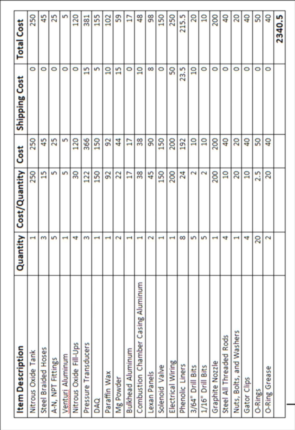
31 Budget 26
32 27 Appendix B HRM Test Fire Procedures Location & Safety a. Consent will be obtained from the Aerospace and Mechanical Engineering Department, the project advisor, and the University of Arizona Risk Management prior to testing. b. The project advisor will be present for ALL test fires c. Under NO circumstances will anyone other than team members and approved advisors be allowed to be near the rocket during test firings. d. Test firings will be located on a private lot located at the end of Ina to the west of I-10 e. The test stand will be positioned in the vacant dirt area located at the furthest point east of the unoccupied building. All loose debris and potential fire hazards will be removed within a 10ft radius prior to setting up the test stand. The exhaust plume will be facing an 8ft dirt mound to stop any possible projectiles. f. ALL test fires will be done remotely via an electronic switch which operates the solenoid valve. All members will be inside a brick garage that will act as a blast bunker while the rocket is armed, which is located 75ft from the hybrid rocket test stand. g. Live feed video viewing the tank pressure gauge and the fuel cell will be running during ALL test fires. This allows real time readings giving the ability to stop the oxidizer supply to the combustion chamber before any catastrophic failure occurs h. Ear Protection will be worn at all times during the test fire. i. Each test fire will last a maximum of 5 seconds and then will shut down to obtain the necessary data from the fuel grain. j. There will be at least two class D fire extinguishers present at all times as well as a bucket of dry sand in case of a fire. k. After each test fire the rocket will be allowed to cool for no less than 30 minutes before switching fuel grains. l. 911 will be called in case of an emergency. Procedures 1. Obtain necessary pre-test fire data 2. Make sure oxidizer tank valve is off and disconnected 3. Install fuel cell into test stand 4. Hook up hoses in the following order: a. Injector Bulkhead to the Venturi b. Venturi to the Solenoid Valve 5. Make sure solenoid valve is in the OFF position 6. Dry test the solenoid value without opening the oxidizer valve to ensure functionality of the solenoid valve before test firing. 7. Install live feed camera and ensure proper functioning for viewing pressure gauge on oxidizer tank and the fuel cell 8. Only one person is allowed in the test fire area to install ematch, a slender conducting wire that is used to pre-heat the pre combustion chamber. 9. The designated person will ensure all hoses are properly connected 10. The designated person will open the oxidizer tank valve while the solenoid valve is kept OFF 11. The final person vacates the test fire area 12. Turn on Data Acquisition for data recording 13. Commence test fire 14. Disconnect power to the solenoid valve
33 28 Clean Up & Disposal 15. Wait one minute, then have one person turn off oxidizer tank valve 16. Wait 30+ min before approaching test stand 17. Remove fuel grain 18. Obtain necessary post data (see template to be filled out for each test fire) 19. Repeat steps 2-22 for each new fuel grain 20. Use empirical data from burst fires to calculate burn rate exponent and coefficient 21. Use burn rate exponent and coefficient and full test fire data to compile mass flow rate of the oxidizer, mass flow rate of the fuel, thrust and specific impulse for each test fire 22. Normalize these results to obtain mass flow rate of the oxidizer, mass flow rate of the fuel, thrust and specific impulse for each type of fuel 1. Close the valve on the oxidizer tank 2. Purge the system of any remaining oxidizer 3. Disconnect the power to the solenoid valve 4. Disconnect the supply hose to the oxidizer tank 5. Disconnect the power supply to the pressure transducers 6. Clean up all extension cords 7. Collect all of the phenolic liners and fuel cells, transport to AME S408 via a crate 8. Transport the test stand and supporting materials to AME S After acquiring any additional data from the fuel cells follow chemical waste disposal procedures 1 a. Container Preparation i. Collect 3.5 gallon plastic (HDPE) pail from UA stores b. Add proper waste identification tag i. List name of person familiar with waste ii. Phone number iii. Building name and lab number iv. Full chemical name of waste c. Request Pick up

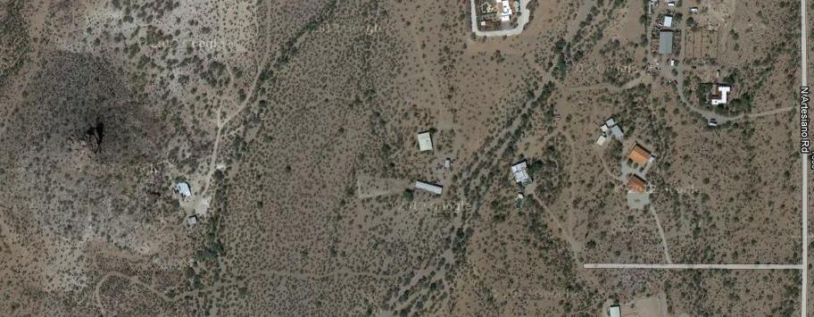

34 Location of test fires 29


35 Location of car which is Enclosed building where Test stand and test fire locations utilized as power source electronics and team are during test fires "Risk Management Services Environmental Compliance Chemical Waste Disposal."Risk Management Services Environmental Compliance Chemical Waste Disposal. N.p., n.d. Web. 05 Feb
36 31 HRM Casting Safety Documents List of Intended Chemicals Nitrous Oxide (Oxidizer) Nitrous oxide acts as the oxidizer in our hybrid rocket. Until being hooked up to the test stand the nitrous tank will be stored, detached from the system, locked in an environmentally controlled backroom within AME S408. This will mitigate potential hazards such as: the tank exploding due to heating, combustion due to contact with the fuel, and inhalation of nitrous vapor. The back room, where the tank will be stored, is cooled to approximately 67 degrees using the centralized air system. Additionally there is no heat source (i.e. computers, sunlight from windows) present. The paraffin wax fuel and nitrous oxide are inert, meaning without a significant amount of heat they will not spontaneously react and combust. As a precaution, the Paraffin wax will be kept in the main room separate from the oxidizer to insure no reaction will occur. Assuming the oxidizer tank does not leak, there will be no risk of inhalation of the vapor. However, as a precaution the tank will be stored in the locked room, should a leak occur, upon entering the room the odor will be present. If this is the case, the main room will be cleared of people and then ventilated. With these precautions in place, the risk due to the nitrous oxide is minimized. The tank will be filled by the U of A Cryogenics and Gas Facility on campus within two days prior to a test fire to prevent prolonged storage of the pressurized tank. We have communicated with staff of this facility and we have determined the procedure for filling a tank. The nitrous oxide purchased from U of A Cryogenics is not medical grade nitrous oxide; this means that there is a small amount of sulfur dioxide to allow for easy detection of leaks and also prevent any potential substance abuse. The nitrous oxide tank was purchased from Don s Hotrod Shop, a business specializing in nitrous systems for automobiles, and was manufactured by Edelbrock. Paraffin Wax (Fuel) Paraffin wax is the primary fuel in the hybrid rocket proposed. Its public use is as basic candle wax. It is appealing to hybrid rocketry because it does not produce any harmful chemical pollutants when combusted; this along with the fact that it is inert makes paraffin wax one of the safest types of fuel to work with in rocketry. Also paraffin wax has an extremely high regression rate (regression rate is basically burn rate) which is an important factor in hybrid rocketry. Lithium Aluminum Tetra Hydride (Proposed Additive 1) Also known as lithium aluminum hydride, this powder will function as an additive to the fuel to enhance performance of the engine. The fuel (paraffin wax) and additive will be premixed before test fires. Lithium hydride is hygroscopic, meaning that it attracts water molecules and even tends to pull water molecules from moister in the air. Additionally lithium aluminum hydride reacts in the presence of water to form lithium hydroxide and flammable hydrogen gas. These two properties are not a good combination, so it is important to keep the LiAlH4 powder from contacting the air. To minimize risk, the container of LiAlH4 will always be
37 32 sealed and stored in a fireproof cabinet, located in AME N231D. It will also only be handled in the nitrogen bag. The MSDS is attached to the container and will be reviewed before the chemical is used. Lithium aluminum hydride begins to decompose at F. One of the products of the decomposition is hydrogen gas. To prevent decomposition keep LiAlH4 and any mixture containing it well below this temperature. Once cast into the paraffin wax fuel grains the lithium aluminum hydride will be safe to store in an oxygen environment. In the paper titled Testing of LiAlH4 as a Potential Additive to Paraffin Wax Hybrid Rocket Fuel, by John DeSain and his coauthors, it is stated that the hydrophobic paraffin wax was found to isolate the LiAlH4 from reaction with both water vapor and upon submerging in liquid water. Risk Potential to react with water to create H2 gas Decomposes at temperatures above F to form H2 gas Mitigation Keep in a sealed container locked in fireproof cabinet. Only handle actual powder in a nitrogen environment until mixed with wax. During the casting process limit the temperature of the wax to 160 o F, which is well below this decomposition temperature. Magnesium Powder (Proposed Additive 2) This will also function as an additive to the fuel to enhance the performance of the engine. It will be pre-mixed before test fires with the fuel (paraffin wax) and additive will be pre-mixed before test fires. Although magnesium poses less of a risk than Lithium Aluminum Tetra Hydride, it will also be sealed and stored in a fireproof cabinet, located in AME N231D. The MSDS is attached to the container and will be reviewed before the chemical is used. One dangerous property of magnesium powder is that if it gets lit it cannot be extinguished with water. So we will have a bucket of sand and a class-d fire extinguisher present at mixings and test firings. Risk Once magnesium powder is lit it cannot be extinguished with water. Mitigation Always have a bucket of sand and a class-d fire extinguisher present.
38 33 Chemical Storage a. The chemical additives will be ordered from Sigma Aldrich and delivered to room S408. b. Until they are needed these additives will be kept in sealed containers stored in a fireproof cabinet in room AME N231D. c. The empty tank will be carried to the University of Arizona Cryogenics (1118 E. 4 th Street, Room 164). It will then be filled by an URIC technician. It will be taken and stored in the locked backroom of AME S408 (AME 408A), as previously described. The duration of storage will be minimal, filling the tank on a Friday, storing it overnight, and then be used for test firing Saturday morning. d. The series of tests should utilize all of the nitrous oxide. After the completion of all test fires the empty nitrous oxide bottle will be stored in room AME S408. Fuel Grain Casting a. The fuel grains will be cast in room AME N417B under an approved fume hood. b. The paraffin wax will be heated using a hot plate provided by Photometrics, under a fume hood. A large stainless steel pot will contain the wax as it is liquefied to a temperature of 160 o F. This temperature is below F where the decomposition of lithium aluminum hydride occurs but above the melting point of paraffin wax. A large analog stem thermometer purchased from McMaster-Carr is used to monitor the temperature. The wax will be consistently mixed to ensure the distribution of heat is uniform. c. The mixing of additives will occur in a sealed glove bag (purchased from Sigma Aldrich) that is filled with nitrogen obtained from UA Cryogenics and Compressed Gas Facility. d. The sealed additive container will be placed into the bag along with a scale. The scale purchased from Harbor Freight reads up to 1000 grams. After the bag is sealed the additive container will be opened, and the needed amount of additive will be measured. Afterwards, the additive container will be re-sealed, and the measured additive will be removed from the nitrogen bag. It will then be immediately mixed thoroughly in the melted wax. To be clear, the wax will still be heating on the hot plate while the additive is mixed in. e. Once the additive is mixed with the wax it will be safe to work with in an oxygen environment because of the hydrophobic properties of the wax. f. After thoroughly being mixed the wax/additive are poured into the fuel grain mold and allowed to cool to ambient in the fume hood. g. The fuel grains will be made on the day before testing as to prevent potential hazards from storing the fuel grain. They will be transported to and stored overnight in AME S408. Once casted the fuel/additive combination has minimal risk and is safe to be store and handled in air. General Safety a. During the casting process only two to three team members will be present. All members present will have long hair pulled back, no loose hanging items, i.e. jewelry, and have closed toed shoes. Also lab coats will be worn at all times.
39 34 b. Nitrile gloves, chemical resistant protected eyewear, and respirator masks will be worn at all times during the casting process. c. A class D fire extinguisher will be present and within reach at all times. In case of LiAlH 4 fire, a bucket of dry sand will be present and within reach to extinguish a potential fire. d. Dry sand and the fire extinguisher will also work for any potential fire induced by the magnesium powder. e. All hazardous materials will be handled and sealed in a nitrogen environment. f. NO Water will be present near the additives. A wash station will be close by in case of an emergency, as well as for cleanup. g. No food or drinks will be present during the casting process and all hands will be washed and thoroughly dried before gloves are put on. Appendix C Thermochemical Calculations To proceed with this approach, the stoichiometric reaction between paraffin and nitrous oxide was found to be the following: This formula assumes complete combustion of the reactants. The Steady-Flow Energy Equation will be used in later calculations, but is defined by the following: (C1) ( ) ( ) (C2) There will be no external work in the process and an adiabatic combustion will be assumed, (W = Q = 0). The above formula will become: ( ) ( ) (C3) All the enthalpy values will need to be determined for the products and reactants. Since the combustion will occur at high temperatures, the coefficients of thermodynamic properties are defined for each product using the following data from NASA xx. ( ) ( ( ) ( ) ( ) ( )
40 35 ( ) ( ( ) ( ) ( ) ( ) ( ) ( ( ) ( ) ( ) ( ) The heat of combustion for Paraffin wax was referenced from Coefficients for Calculating Thermodynamic and Transport Properties of Individual Species by McBride, Gordon, and Reno and determined to be: (C4) Heat of formation also needs to be determined for paraffin wax, but this will need to be calculated. Assuming that the reaction happens in air, the enthalpy values would be known except for the heat of formation; the stoichiometric equation for this reaction is found to be: And thus, ( ) (C5) After this calculation has been done, which can be seen in the MatLab code attached, the heat of formation for Paraffin wax was determined to be: Now all the information is needed to complete the Steady-Flow Energy Equation listed above and this can be reduced to equation (C6) and plugging in values will provide equation (C7). Assuming the reaction takes place at room temperature the ambient temperature is 298K and the equations become: ( ) ( ) ( ) ( ) (C8) (C6) (C7) ( ) ( ) ( ) (C9) Once these calculations were all ran, the temperature of the combustion chamber was found to be:
41 36 This is about 1000 Kelvin above known assumptions, but the process for these calculations have been verified and deemed accurate. What this means though is that there is not a complete combustion that takes place and the products dissociate into minor species as shown in by the following stoichiometric equation: Appendix D Acknowledgements (C10) The team would like to thank: AIAA Student Branch, University of Arizona For funding the entire project, allowing the use of the laboratory as a work space and the use of tools and materials to complete the project. James Villarreal, Energetics and Propulsion, Raytheon For advising the team throughout the course of the entire project, offering guidance and suggestion anywhere and everywhere needed Marsh McCoy, Senior Mechanical Engineer, Photometrics, For the use of his land for test fire purposes. AME Department, University of Arizona For allowing the use of the fume hoods to mix and cast potentially hazardous chemicals and their continued support and guidance throughout the project. OLT Fabrication For fabrication and donation of steel table. Risk Management & Safety, University of Arizona For reviewing all safety documents and procedures to ensure the continued safety of the design team. References i Hybrid Rocket Propulsion. Space Propulsion Group, Inc. < ii DeSain, John D. ; Curtiss, Thomas J. ; Cohen, Ronald B. ; Brady, Brian B. ; Frolik, Steven A. Testing of LiAlH4 as a Potential Additive to Paraffin Wax Hybrid Rocket Fuel. Aerospace Corporation. 30 Oct iii Oxidizer. Space Propulsion Group, Inc. < iv Sutton, George; Biblarz, Oscar. Nozzle Theory and Thermodynamic Relations. Rocket Propulsion Elements. 8 th ed Pgs v Sutton, George; Biblarz, Oscar. Nozzle Theory and Thermodynamic Relations. Rocket Propulsion Elements. 8 th ed Pgs 48 vi < kit/page4> vii Li-jun Yang, Qing-fei Fu, Yuan-Yuan Qu, Wei Zhang, Ming-long Du, Bing-rui Xu. Spray Characteristics of Gelled Propellants in Swirl Injectors. Fuel. July viii Li-jun Yang, Qing-fei Fu, Yuan-yuan Qu, Wei Zhang, Ming-long Du, Bing-rui Xu. Spray Characteristics of Gelled Propellants in Swirl Injectors. Fuel. July ix Oxidizer. Space Propulsion Group, Inc. < x Erickson, Ryan. Numerical Modeling of a Hybrid Rocket. University of Minnesota Duluth, Department of Mechanical Engineering. Spring 2005.
42 37 xi 6061 Aluminum. Aerospace Specification Metals Inc. < xii 4310 Steel. Aerospace Specification Metals Inc. < xiii Rasor, N.S. McClelland, J.D. Thermal Properties of Graphite, Molybdenum, and Tantalum to their Destruction Temperatures. Journal of Physics and Chemistry of Solids. (1960): < xiv Sutton, George; Biblarz, Oscar. Isentropic Flow Through Nozzles. Rocket Propulsion Elements. 8 th ed Pgs xv Post Combustion Chambers. Hybrid Rocket Motors. < xvi 4310 Steel. Aerospace Specification Metals Inc. < xvii Sutton, George; Biblarz, Oscar. Hybrid Propellant Rockets. Rocket Propulsion Elements. 8 th ed Pgs xviii Karabeyoglu, Arif. Hybrid Rocket Propulsion For Future Space Launch. Space Propulsion Group, Inc. and Stanford University. 9 May Pg 17. xix Development and Testing of Paraffin-Based Hybrid Rocket Fuels, Karabeyoglu, Cantwell, Altman xx McBride, Bonnie; Gordon, Sanford; Reno, Martin; NASA TM Coefficients for Calculating Thermodynamic and Transport Properties of Individual Species, NASA, 1993 Appendix E AIAA Student Conference Paper 2 nd Place Finish (See Attached)
43 Investigation of Paraffin Fuels and Additives in Hybrid Rocket Motors Brian Franz 1, Doug Mason 2, Daniel Murphey 3, Spencer Sasarita 4, Robert Schultz 5 University of Arizona, Tucson AZ, In comparison to solid and liquid fueled rockets, hybrids are attractive for their relatively low cost, simple design, and safety, while combining some of the characteristics of both liquid and solid fueled rockets. This paper describes a hybrid rocket motor (HRM) design that was constructed for testing fuels with little to no known experimental data. The HRM utilizes nitrous oxide as the propellant oxidizer and will be chemically combusted with paraffin wax based fuels. Paraffin wax is a relatively new type of hybrid rocket fuel and has ample opportunity for research. The paraffin wax will be tested alone as a baseline comparison test as well as mixed with two additives: lithium aluminum hydride and magnesium powder. These additives will act as performance enhancers in the fuel grain with each additive mixed at 5% and 10% of the fuel mass. This project will allow for 25 total test fires with different propellant combinations. The data will be compiled, analyzed, and will give insight to the magnitude in which the new type of fuel and/or the use of additives affect the efficiency of the hybrid rocket engine. Nomenclature a - Regression Rate Coefficient A 1 - Large Venturi Port Area A 2 - Small Venturi Port Area - Burn Area A e - Nozzle Exit Area A t - Nozzle Throat Area C f - Thrust Coefficient HRM - Hybrid Rocket Motor I SP - Specific Impulse - Fuel Mass Flow Rate - Oxidizer Mass Flow Rate n - Regression Rate Exponent P 1 - Venturi Pressure 1 P 2 - Venturi Pressure 2 P a - Ambient Pressure P CC - Combustion Chamber Pressure P e - Nozzle Exit Pressure - Regression Rate T - Thrust t b - Burn Time W f - Final Fuel Grain Weight W i - Initial Fuel Grain Weight γ - Specific Heat Ratio - Oxidizer Density - Fuel Density 1 Undergraduate Student, University of Arizona, AIAA Student Member 2 Undergraduate Student, University of Arizona, AIAA Student Member 3 Undergraduate Student, University of Arizona, AIAA Student Member 4 Undergraduate Student, University of Arizona, AIAA Student Member 5 Undergraduate Student, University of Arizona, AIAA Student Member 1 American Institute of Aeronautics and Astronautics

44 I. Introduction Existing rockets most commonly utilize solid or liquid rocket motors. Solid rocket motors are chosen when simplicity and high thrust are needed, while liquid rocket engines are chosen because of their high efficiency and throttling/shutdown capabilities. Hybrid rocket motors are a combination of both liquid and solid rocket engines. They utilize a liquid oxidizer similar to that of liquid engines and an inert solid fuel grain. This results in performance characteristics that fall between solid and liquid rockets. For example, hybrid rockets are typically designed to have higher thrust than liquid rockets but lower than that of solid rockets while having higher efficiency than solid rockets but lower than liquid rockets. They also have the same throttling/shutdown capability as liquid engines. Lastly, hybrid rockets are the safest because, in addition to having shutdown capabilities, the solid fuel and liquid oxidizer are also inert when separated. Hybrid motors provide a compromise between thrust and efficiency while exceeding all other forms in safety, which is evidence that hybrid rockets are clearly a viable choice for future propulsive needs. This project consists of two main goals. The first of these goals is to build a working hybrid rocket engine test stand that has a safety shut off switch for the oxidizer flow, reloadable fuel cell, and has an operational data acquisition system (DAQ). The second is to mix, cast, and test fire a newer and cleaner type of fuel, paraffin (candle) wax, with and without additives that act as performance enhancers. Then the team will use the acquired data to calculate the regression rate and efficiency of each fuel combination, i.e. the specific impulse of the motor (I SP ). II. Hybrid Theory The propellant chosen for this hybrid engine was paraffin wax (C 20 H 42 ) as the fuel and nitrous oxide (N 2 O) as the oxidizer. Nitrous oxide was chosen because it is non-toxic, easy to store, stable at room temperature, relatively cheap, and easy to acquire i. Paraffin wax was chosen because it has been shown to greatly increase burn rate and overall performance of hybrid motors. This is due to a liquid boundary layer that forms over the fuel grain as it burns as seen in Figure 1. Because of the liquid layer, droplets of fuel form on the surface of the boundary layer allowing them to get caught in the oxidizer stream as it passes, creating a fuel rich mixture throughout the grain. This oxidizer stream begins to act like a spray nozzle for fuel and increases the fuel mass transfer of the system ii. Oxidizer Supply Boundary Layer Oxidizer Rich Zone Liquefied Paraffin Fuel/Fuel Rich Zone Combustion Boundary Solid Paraffin Fuel Figure 1: Hybrid Engine Combustion Chamber Mixing Layer 2 American Institute of Aeronautics and Astronautics
45 Isp (s) One of the most important parameters in measuring the performance of a hybrid rocket motor is the regression rate of the fuel, which is calculated by the equation: (1) Empirical data for paraffin wax and gaseous nitrous oxide was determined by Karabeyoglu iii for the a and n values as and 0.62, respectively. These values will be later verified or modified depending on the outcome of the hybrid motor firings. The above were used to initially size the motor grain for these experiments. The propellant thermochemical calculation program, ProPEP iv, was used to determine propellant characteristics (ratio of specific heats, stagnation temperature, specific impulse, etc.) for a range of oxidizer to fuel ratios in order to find the optimum oxidizer-fuel ratio. By using the optimum oxidizer to fuel ratio seen by this engine over the duration of a test fire, found in Figure 2 to be about 6:1, and the oxidizer tank pressure as well as the nozzle geometry, the program can determine the useful theoretical propellant parameters and calculations as calculated in Table 1. These theoretical values will be the baseline for which to compare the results of the project O/F Figure 2: Specific Impulse vs O/F Ratio for Paraffin/N 2 O Table 1: Paraffin/N 2 O Combustion Parameters at Optimum O/F Ratio Paraffin/N 2 O Combustion Parameters at Optimum O/F Ratio Oxidizer-Fuel Ratio, O/F 6 Specific Heat Ratio, γ 1.28 Propellant Density, ρ (lb/ft 3 ) Characteristic Velocity, C * ( ft/s) Combustion Chamber Pressure, P cc (lb/in 2 ) 330 Thrust, T (lb) Theoretical Specific Impulse, I SP (s) American Institute of Aeronautics and Astronautics

46 III. Design and Fabrication The design of this hybrid rocket engine was done in three parts: the nozzle, the oxidizer delivery system, and the combustion chamber. Each is discussed in the following sub-sections. Nozzle: The nozzle for this system was designed to have an expansion ratio of four to allow for the most time spent perfectly expanded over the course of a test fire based on the theoretical calculations in Table 1. This was designed in order to simplify the generic thrust equation given by equation 2 to the perfectly expanded thrust equation given by equation 3; this simplification occurs because the thrust due to pressure is zero when the nozzle exit pressure is equal to the ambient pressure v. where C f is the thrust coefficient given by equation 4: (2) (3) ( ) (4) The nozzle, seen in Figure 3, was professionally machined out of graphite due to its exceptional thermal resistivity vi. Figure 3a: Graphite Nozzle Figure 3b: Section View Graphite Nozzle Oxidizer Delivery System: The oxidizer delivery system was designed around the injector design. In the technical paper "Effects of Swirl Injector Design on Hybrid Rocket Fuel Regression Rate" by Raul Lugo, it is concluded that "Swirl injectors have the ability to improve motor performance and efficiencies. Previous research has shown that injectors producing a strong central toroidal recirculation zone will result in a stable combustion and higher regression rate than axial flow vii. The injector for this system is a swirl injector with 16 equally spaced radial holes on a 50 degree angle from the tangent and 8 axial holes, each with a diameter of 3/64. A computational fluid dynamics (CFD) analysis of the injector was performed using SolidWorks FlowSim 6 ; the CFD analysis and the cold flow tests confirm the presence of the characteristic swirl of swirl injectors (see figures 4 and 5). 6 CFD analysis was completed to determine if the injector would have good swirl characteristics. A constant mass flow rate of the oxidizer of magnitude 0.33 lbs/s was in the input boundary condition of the injector for the duration of the test fire. The other boundary condition was a constant pressure load experienced by the chamber 4 American Institute of Aeronautics and Astronautics
.")


47 Figure 4: Injector FlowSim Figure 5: Injector Cold Flow Combustion Chamber: The combustion chamber was designed to have the ability to insert phenolic liners into a tube so the propellant grains could be swapped out quickly when multiple test fires are necessary (see figure 6). By modeling the combustion chamber as a closed, flat end pressure vessel, the finite element analysis program, ANSYS, used to conduct a structural loading analysis for the duration of an average test fire 7. Figure 7 shows this analysis and the maximum stress of 4.15 MPa while aluminum 6061 has a yield stress of 24.7 MPa suggesting that aluminum is a viable choice for the combustion chamber tubing material viii. Figure 6: Combustion Chamber Tube with Fuel Grain Insert Figure 7: Von Mises Equivalent Stress Analysis IV. Experimental Test Setup The test stand is designed and constructed to guarantee the safety of the team members conducting the test while also allowing for accurate data collection. The entire test stand is constructed walls of 500 lb/in 2 during the duration of the test fire. These were done to simulate the real conditions the injector/combustion chamber would experience during a test fire. 7 ANSYS analysis was completed to determine if the combustion chamber would rupture under the pressure of the given testing conditions. The combustion chamber was modeled as a hollow, cylindrical pressure vessel with fixed end caps as the boundary conditions. The loading condition was an internal, uniform pressure load acting on the internal surface areas of the cylinder and the end caps. 5 American Institute of Aeronautics and Astronautics
.")
48 from ¼ steel panels, other than one side and top which are ½ Lexan panels for ease of viewing; this setup allows a horizontally mounted hybrid rocket engine to be tested while limiting any potential damage to anything directly behind the test stand (which is a highly controlled area). Additionally the weight of the steel keeps the test stand stationary, eliminating the need to secure the test stand to the ground. A vertically fired version of this test stand (firing towards the ground) was proposed but eliminated due to the paraffin wax s potential to melt, drip and clog the injector while the engine is cooling. Before testing, the test stand is carried to the desired location, and the power and data acquisition wiring is arranged and connected to the recording laptop as well as the three individual pressure transducers. Before the power supply is turned on or the oxidizer tank is opened, an igniter made from an e-match, pyrogen, and a small piece of solid rocket propellant is inserted into the pre-combustion chamber. The combustion chamber is then inserted between the two bulkheads and the all-threads are tightened to ensure a sealed compression fit. Non-flammable grease and O-rings are placed between the combustion chamber and the injector bulkhead at the same time that the nozzle and its bulkhead are greased and compression-fit onto the other end. The oxidizer tank is cracked open to check for leaks, and then opened fully. The area around the test stand is cleared, except for one person who connects the igniter to the power supply and the control box and then turns on the power supply and retreats to a safe distance. Figure 8 shows a close up view of the test stand set up for firing as described above. Figure 8: Hybrid Rocket Engine Test Stand Nominal values of the pressure transducers are checked and the test area is visually checked to be clear for the test fire. The data acquisition begins to record data and then the igniter is lit in order to heat the fuel grain. As soon as that burns out, the solenoid valve is opened, which initiates oxidizer flow. When the oxidizer meets the preheated fuel grain in the pre-combustion chamber, the rocket engine ignites and the fuel grain begins to regress. After allowing for a 2-3 second burn, the solenoid valve is closed and the engine is left to cool for approximately 15 minutes before approaching and dismantling the assembly. V. Results The analysis of the data was done in several steps. First, the mass flow rate of the fuel was calculated by recording the weight of the fuel grain before and after a test fire and using the burn time in the equation: (5) Second, the mass flow rate of the oxidizer is calculated using the average voltage measurements from the two pressure transducers connected to the venturi over the duration of the burn time. These 6 American Institute of Aeronautics and Astronautics
49 voltage measurements are converted to pressures and used in the oxidizer mass flow rate equation along with the density of the oxidizer as well as the area differential in the venturi according to the equation: (6) Finally, the thrust is calculated via equation (3), and the specific impulse for each test fire can be determined by the equation: (7) The results for two of the paraffin-only test fires are presented in Figure 9 and Tables 2 and 3. Paraffin Grain #3 Paraffin Grain # PT 1 -PT 2 -CC PT 1 -PT 2 -CC Pressure (lbf/ft s ) Pressure (lbf/ft s ) Time (s) Time (s) Figure 9: Pressure Data for P 1, P 2, P CC for Paraffin-only grain 3 and 4 Table 2: Paraffin-only Grain 3 and 4 Data and Results Paraffin-only Grain 3 Paraffin-only Grain 4 Initial Weight, W i (lbf) Final Weight, W f (lbf) Venturi Pressure 1, P 1 (lbf/in 2 ) Venturi Pressure 2, P 2 (lbf/in 2 ) Combustion Chamber Pressure, P cc (lbf/in 2 ) Burn Time, t b (s) American Institute of Aeronautics and Astronautics
 115.0 123.3 120.7 4.72 2.")
50 Fuel Mass Flow Rate, (lbf/s) Oxidizer Mass Flow Rate, (lbf/s) O/F Ratio Thrust, T (lbf) Specific Impulse, I SP (s) Table 3: Paraffin-only Grain 3 and 4 Results and Comparison Paraffin-only Grain 3 Paraffin-only Grain 4 Theoretical Grain 3 Error Grain 4 Error Thrust, T (lbf) Specific Impulse, I SP (s) VI. Conclusion and Future Work The team has successfully designed, built and tested the hybrid rocket engine test stand. In comparison to the theoretical values, the two test fires presented are very close in the value of thrust, only off by 4.72 % and 2.15 % for paraffin-only grain 3 and 4, respectively. Specific impulse was a bit further off with errors of 21.3% and 23.4 % for 3 and 4, respectively. The error in the thrust value is directly related to a lower measured combustion chamber pressure than the assumed value used to design the nozzle expansion ratio. The low combustion chamber pressure causes the nozzle to not be expanded properly because the assumed chamber pressure was much higher. This is confirmed by Figure 10, which shows the Mach diamond pattern formed by the expansion waves that form at the nozzle exit plane because the nozzle is under expanded. This a direct correlation to the thrust produced being less than the theoretical value for grain 4: an over expanded nozzle has an exit pressure less than that of the ambient air pressure and therefore decreases the thrust production of the motor. Figure 10: Mach Diamond Formation during Test Fire 8 American Institute of Aeronautics and Astronautics
Hybrid Rocket Motor (HRM) Test Stand:An Investigation of the Effects of Additives
 Test Stand:An Investigation of the Effects of Additives") Hybrid Rocket Motor (HRM) Test Stand:An Investigation of the Effects of Additives Item Type text; Electronic Thesis Authors Sasarita, Spencer Cole Publisher The University of Arizona. Rights Copyright
Hybrid Rocket Motor (HRM) Test Stand:An Investigation of the Effects of Additives Item Type text; Electronic Thesis Authors Sasarita, Spencer Cole Publisher The University of Arizona. Rights Copyright
CONTENTS Duct Jet Propulsion / Rocket Propulsion / Applications of Rocket Propulsion / 15 References / 25
 CONTENTS PREFACE xi 1 Classification 1.1. Duct Jet Propulsion / 2 1.2. Rocket Propulsion / 4 1.3. Applications of Rocket Propulsion / 15 References / 25 2 Definitions and Fundamentals 2.1. Definition /
Testing and Manufacturing Update. 4/6/2015 Kisa Brostrom, Kent Evans
 Testing and Manufacturing Update 4/6/2015 Kisa Brostrom, Kent Evans 1 Our Main Problem 2 Rocket Classes Cutoff Total Impulse http://www.nar.org/standards-and-testing-committee/standard-motor-codes/ 3 Our
HERCULES-2 Project. Deliverable: D8.8
 HERCULES-2 Project Fuel Flexible, Near Zero Emissions, Adaptive Performance Marine Engine Deliverable: D8.8 Study an alternative urea decomposition and mixer / SCR configuration and / or study in extended
Development and Testing of a Small Hybrid Rocket Motor for Space Applications
 Enrico Paccagnella 22 September 2017 Development and Testing of a Small Hybrid Rocket Motor for Space Applications Università degli Studi di Padova Centro di Ateneo di Studi e Attività Spaziali Giuseppe
Thermal Stress Analysis of Diesel Engine Piston
 International Conference on Challenges and Opportunities in Mechanical Engineering, Industrial Engineering and Management Studies 576 Thermal Stress Analysis of Diesel Engine Piston B.R. Ramesh and Kishan
Design Rules and Issues with Respect to Rocket Based Combined Cycles
 Respect to Rocket Based Combined Cycles Tetsuo HIRAIWA hiraiwa.tetsuo@jaxa.jp ABSTRACT JAXA Kakuda space center has been studying rocket based combined cycle engine for the future space transportation
Media Event Media Briefing Arif Karabeyoglu President & CTO SPG, Inc. June 29, 2012
 Media Event Media Briefing Arif Karabeyoglu President & CTO SPG, Inc. June 29, 2012 spg-corp.com SPG Background SPG, Inc is an Aerospace company founded in 1999 to advance state-of of-the-art propulsion
University Turbine Systems Research Industrial Fellowship. Southwest Research Institute
 Correlating Induced Flashback with Air- Fuel Mixing Profiles for SoLoNOx Biomass Injector Ryan Ehlig University of California, Irvine Mentor: Raj Patel Supervisor: Ram Srinivasan Department Manager: Andy
SAE Mini BAJA: Suspension and Steering
 SAE Mini BAJA: Suspension and Steering By Zane Cross, Kyle Egan, Nick Garry, Trevor Hochhaus Team 11 Progress Report Submitted towards partial fulfillment of the requirements for Mechanical Engineering
NEW MEXICO STATE UNIVERSITY
 Fall 2011 [HYBRID ROCKET TEAM] NEW MEXICO STATE UNIVERSITY Portable hybrid rocket motors and test stands can be seen in many papers, but none have been reported on the design or instrumentation at such
COMPUTATIONAL FLOW MODEL OF WESTFALL'S 2900 MIXER TO BE USED BY CNRL FOR BITUMEN VISCOSITY CONTROL Report R0. By Kimbal A.
 COMPUTATIONAL FLOW MODEL OF WESTFALL'S 2900 MIXER TO BE USED BY CNRL FOR BITUMEN VISCOSITY CONTROL Report 412509-1R0 By Kimbal A. Hall, PE Submitted to: WESTFALL MANUFACTURING COMPANY May 2012 ALDEN RESEARCH
Effects of Dilution Flow Balance and Double-wall Liner on NOx Emission in Aircraft Gas Turbine Engine Combustors
 Effects of Dilution Flow Balance and Double-wall Liner on NOx Emission in Aircraft Gas Turbine Engine Combustors 9 HIDEKI MORIAI *1 Environmental regulations on aircraft, including NOx emissions, have
CFD Analysis on a Different Advanced Rocket Nozzles
 International Journal of Engineering and Advanced Technology (IJEAT) CFD Analysis on a Different Advanced Rocket Nozzles Munipally Prathibha, M. Satyanarayana Gupta, Simhachalam Naidu Abstract The reduction
Experimental Testing of a Rotating Detonation Engine Coupled to Nozzles at Conditions Approaching Flight
 25 th ICDERS August 2 7, 205 Leeds, UK Experimental Testing of a Rotating Detonation Engine Coupled to Nozzles at Conditions Approaching Flight Matthew L. Fotia*, Fred Schauer Air Force Research Laboratory
FRONTAL OFF SET COLLISION
 FRONTAL OFF SET COLLISION MARC1 SOLUTIONS Rudy Limpert Short Paper PCB2 2014 www.pcbrakeinc.com 1 1.0. Introduction A crash-test-on- paper is an analysis using the forward method where impact conditions
Module7:Advanced Combustion Systems and Alternative Powerplants Lecture 32:Stratified Charge Engines
 ADVANCED COMBUSTION SYSTEMS AND ALTERNATIVE POWERPLANTS The Lecture Contains: DIRECT INJECTION STRATIFIED CHARGE (DISC) ENGINES Historical Overview Potential Advantages of DISC Engines DISC Engine Combustion
Design, Construction and Testing of a Desktop Supersonic Wind Tunnel
 Design, Construction and Testing of a Desktop Supersonic Wind Tunnel Vi H. Rapp, Jennifer Jacobsen, Mark Lawson, Andrew Parker, Kuan Chen * Department of Mechanical Engineering University of Utah Salt
SAE Mini BAJA: Suspension and Steering
 SAE Mini BAJA: Suspension and Steering By Zane Cross, Kyle Egan, Nick Garry, Trevor Hochhaus Team 11 Project Progress Submitted towards partial fulfillment of the requirements for Mechanical Engineering
Experiments in a Combustion-Driven Shock Tube with an Area Change
 Accepted for presentation at the 29th International Symposium on Shock Waves. Madison, WI. July 14-19, 2013. Paper #0044 Experiments in a Combustion-Driven Shock Tube with an Area Change B. E. Schmidt
Remote Control Helicopter. Engineering Analysis Document
 Remote Control Helicopter By Abdul Aldulaimi, Travis Cole, David Cosio, Matt Finch, Jacob Ruechel, Randy Van Dusen Team 04 Engineering Analysis Document Submitted towards partial fulfillment of the requirements
Supersonic Combustion Experimental Investigation at T2 Hypersonic Shock Tunnel
 Supersonic Combustion Experimental Investigation at T2 Hypersonic Shock Tunnel D. Romanelli Pinto, T.V.C. Marcos, R.L.M. Alcaide, A.C. Oliveira, J.B. Chanes Jr., P.G.P. Toro, and M.A.S. Minucci 1 Introduction
Numerical simulation of detonation inception in Hydrogen / air mixtures
 Numerical simulation of detonation inception in Hydrogen / air mixtures Ionut PORUMBEL COMOTI Non CO2 Technology Workshop, Berlin, Germany, 08.03.2017 09.03.2017 Introduction Objective: Development of
FAST COOK-OFF REACTION IMPROVEMENT OF THE 2.75-INCH ROCKET MOTOR
 FAST COOK-OFF REACTION IMPROVEMENT OF THE 2.75-INCH ROCKET MOTOR Steven S. Kim Indian Head Division Naval Surface Warfare Center Indian Head, Maryland ABSTRACT This paper is intended to summarize the development
Investigation of Direct-Injection via Micro-Porous Injector Nozzle
 Investigation of Direct-Injection via Micro-Porous Injector Nozzle J.J.E. Reijnders, M.D. Boot, C.C.M. Luijten, L.P.H. de Goey Department of Mechanical Engineering, Eindhoven University of Technology,
Today, we re going to talk about battery safety. We ll discuss all the key issues associated with using batteries safely, including battery hazards,
 Today, we re going to talk about battery safety. We ll discuss all the key issues associated with using batteries safely, including battery hazards, battery charging, and battery maintenance. Although
Waste Heat Recovery from an Internal Combustion Engine
 Waste Heat Recovery from an Internal Combustion Engine Design Team Josh Freeman, Matt McGroarty, Rob McGroarty Greg Pellegrini, Ming Wood Design Advisor Professor Mohammed Taslim Abstract A substantial
R&D on Oil-Burning, Environment - Friendly, High-Efficiency Boiler
 2001.M4.3.1 R&D on Oil-Burning, Environment - Friendly, High-Efficiency Boiler (Environment-Friendly, High-Efficiency Boiler Group) Takashi Murakawa, Hiroshi Kato, Hiroshi Matsumoto, Kentaro Sato, Yasuhiro
M:2:I Milestone 2 Final Installation and Ground Test
 Iowa State University AerE 294X/AerE 494X Make to Innovate M:2:I Milestone 2 Final Installation and Ground Test Author(s): Angie Burke Christopher McGrory Mitchell Skatter Kathryn Spierings Ryan Story
Development of Low-thrust Thruster with World's Highest Performance Contributing to Life Extension of Artificial Satellites
 Development of Low-thrust Thruster with World's Highest Performance Contributing to Life Extension of Artificial Satellites 40 NOBUHIKO TANAKA *1 DAIJIRO SHIRAIWA *1 TAKAO KANEKO *2 KATSUMI FURUKAWA *3
Combustion Equipment. Combustion equipment for. Solid fuels Liquid fuels Gaseous fuels
 Combustion Equipment Combustion equipment for Solid fuels Liquid fuels Gaseous fuels Combustion equipment Each fuel type has relative advantages and disadvantages. The same is true with regard to firing
IAC-15-C4.3.1 JET INDUCER FOR A TURBO PUMP OF A LIQUID ROCKET ENGINE
 IAC-15-C4.3.1 JET INDUCER FOR A TURBO PUMP OF A LIQUID ROCKET ENGINE Martin Böhle Technical University Kaiserslautern, Germany, martin.boehle@mv.uni-kl.de Wolfgang Kitsche German Aerospace Center (DLR),
ME3264: LAB 9 Gas Turbine Power System
 OBJECTIVE ME3264: LAB 9 Gas Turbine Power System Professor Chih-Jen Sung Spring 2013 A fully integrated jet propulsion system will be used for the study of thermodynamic and operating principles of gas
R&D on a Medium-speed, Four-cycle Diesel Engine Using Heavy fuel oil
 1999C.4.1.11 R&D on a Medium-speed, Four-cycle Diesel Engine Using Heavy fuel oil 1. R&D contents 1.1 Background and R&D objectives In order to meet increasing demand for light oil and intermediate fraction,
Combustion characteristics of n-heptane droplets in a horizontal small quartz tube
 Combustion characteristics of n-heptane droplets in a horizontal small quartz tube Junwei Li*, Rong Yao, Zuozhen Qiu, Ningfei Wang School of Aerospace Engineering, Beijing Institute of Technology,Beijing
Component and System Level Modeling of a Two-Phase Cryogenic Propulsion System for Aerospace Applications
 Component and System Level Modeling of a Two-Phase Cryogenic Propulsion System for Aerospace Applications J. LoRusso, B. Kalina, M. Van Benschoten, Roush Industries GT Users Conference November 9, 2015
EFFECT OF INJECTION ORIENTATION ON EXHAUST EMISSIONS IN A DI DIESEL ENGINE: THROUGH CFD SIMULATION
 EFFECT OF INJECTION ORIENTATION ON EXHAUST EMISSIONS IN A DI DIESEL ENGINE: THROUGH CFD SIMULATION *P. Manoj Kumar 1, V. Pandurangadu 2, V.V. Pratibha Bharathi 3 and V.V. Naga Deepthi 4 1 Department of
Exercise 4-1. Flowmeters EXERCISE OBJECTIVE DISCUSSION OUTLINE DISCUSSION. Rotameters. How do rotameter tubes work?
 Exercise 4-1 Flowmeters EXERCISE OBJECTIVE Learn the basics of differential pressure flowmeters via the use of a Venturi tube and learn how to safely connect (and disconnect) a differential pressure flowmeter
How Does a Rocket Engine Work?
 Propulsion How Does a Rocket Engine Work? Solid Rocket Engines Propellant is a mixture of fuel and oxidizer in a solid grain form. Pros: Stable Simple, fewer failure points. Reliable output. Cons: Burns
Power Efficient and Restart capable Acrylonitrile Butadiene Styrene Arc Ignitor for Hybrid Rockets
 Power Efficient and Restart capable Acrylonitrile Butadiene Styrene Arc Ignitor for Hybrid Rockets Stephen A. Whitmore, PhD, Associate Professor Daniel P. Merkley, and Nathan R. Inkley, Graduate Research
Jet Aircraft Propulsion Prof. Bhaskar Roy Prof. A.M. Pradeep Department of Aerospace Engineering Indian Institute of Technology, Bombay
 Jet Aircraft Propulsion Prof. Bhaskar Roy Prof. A.M. Pradeep Department of Aerospace Engineering Indian Institute of Technology, Bombay Lecture No. # 04 Turbojet, Reheat Turbojet and Multi-Spool Engines
Chapter 7: Thermal Study of Transmission Gearbox
 Chapter 7: Thermal Study of Transmission Gearbox 7.1 Introduction The main objective of this chapter is to investigate the performance of automobile transmission gearbox under the influence of load, rotational
VENT SILENCER PRODUCT GUIDE
 VENT SILENCER Copyright 200 by PULSCO Incorporated. All rights reserved. Reproduction without permission is prohibited. PRODUCT GUIDE PULSCO VENT SILENCER TABLE OF CONTENTS DESCRIPTION PAGE PULSCO VENT
SUCCESSFUL DIESEL COLD START THROUGH PROPER PILOT INJECTION PARAMETERS SELECTION. Aleksey Marchuk, Georgiy Kuharenok, Aleksandr Petruchenko
 SUCCESSFUL DIESEL COLD START THROUGH PROPER PILOT INJECTION PARAMETERS SELECTION Aleksey Marchuk, Georgiy Kuharenok, Aleksandr Petruchenko Robert Bosch Company, Germany Belarussian National Technical Universitry,
HIGH VELOCITY THERMAL GUN FOR SURFACE PREPARATION AND TREATMENT. I.A. Gorlach
 HIGH VELOCITY THERMAL GUN FOR SURFACE PREPARATION AND TREATMENT I.A. Gorlach Department of Industrial Engineering School of Process and Mechanical Engineering Technikon Witwatersrand Johannesburg, South
Plasma Assisted Combustion in Complex Flow Environments
 High Fidelity Modeling and Simulation of Plasma Assisted Combustion in Complex Flow Environments Vigor Yang Daniel Guggenheim School of Aerospace Engineering Georgia Institute of Technology Atlanta, Georgia
F.I.R.S.T. Robotic Drive Base
 F.I.R.S.T. Robotic Drive Base Design Team Shane Lentini, Jose Orozco, Henry Sick, Rich Phelan Design Advisor Prof. Sinan Muftu Abstract F.I.R.S.T. is an organization dedicated to inspiring and teaching
Bi-Propellant Rocket Motor
 1 Aviate, Navigate, Communicate Bi-Propellant Rocket Motor Prepared by Zechy and Justin 1 2 Bi-Propellant Rocket Motor Our goal is to build a bi-propellant rocket motor that is scalable and cheap to make.
Additively Manufactured Propulsion System
 Additively Manufactured Propulsion System Matthew Dushku Experimental Propulsion Lab 47 South 200 East Providence Utah, 84332 Mdushku@experimentalpropulsionlab.com Small Satellite Conference, Logan UT
THERMAL ANALYSIS OF DIESEL ENGINE PISTON USING 3-D FINITE ELEMENT METHOD
 INTERNATIONAL JOURNAL OF MANUFACTURING TECHNOLOGY AND INDUSTRIAL ENGINEERING (IJMTIE) Vol. 2, No. 2, July-December 2011, pp. 97-102 THERMAL ANALYSIS OF DIESEL ENGINE PISTON USING 3-D FINITE ELEMENT METHOD
Development of Low-Exergy-Loss, High-Efficiency Chemical Engines
 Development of Low-Exergy-Loss, High-Efficiency Chemical Engines Investigators C. F., Associate Professor, Mechanical Engineering; Kwee-Yan Teh, Shannon L. Miller, Graduate Researchers Introduction The
ALCOHOL LOX STEAM GENERATOR TEST EXPERIENCE
 ALCOHOL LOX STEAM GENERATOR TEST EXPERIENCE Klaus Schäfer, Michael Dommers DLR, German Aerospace Center, Institute of Space Propulsion D 74239 Hardthausen / Lampoldshausen, Germany Klaus.Schaefer@dlr.de
Supersonic Nozzle Design for 1µm Laser Sources
 Supersonic Nozzle Design for 1µm Laser Sources Ali Khan Bill O Neill Innovative Manufacturing Research Centre (IMRC) Centre for Industrial Photonics Institute for Manufacturing, Department of Engineering,
SWIRL MEASURING EQUIPMENT FOR DIRECT INJECTION DIESEL ENGINE
 SWIRL MEASURING EQUIPMENT FOR DIRECT INJECTION DIESEL ENGINE G.S.Gosavi 1, R.B.Solankar 2, A.R.Kori 3, R.B.Chavan 4, S.P.Shinde 5 1,2,3,4,5 Mechanical Engineering Department, Shivaji University, (India)
Surface- and Pressure-Dependent Characterization of SAE Baja Tire Rolling Resistance
 Surface- and Pressure-Dependent Characterization of SAE Baja Tire Rolling Resistance Abstract Cole Cochran David Mikesell Department of Mechanical Engineering Ohio Northern University Ada, OH 45810 Email:
Comparing Flow and Pressure Drop in Mufflers
 UNIVERSITY OF IDAHO GAUSS ENGINEERING Comparing Flow and Pressure Drop in Mufflers A Statistical Analysis Jeremy Cuddihy, Chris Ohlinger, Steven Slippy, and Brian Lockner 10/24/2012 Table Of Contents Topic
Connor Needham Roger Williams University Bristol, RI, United States. Jeremy Kacher Roger Williams University Bristol, RI, United States
 ASEE 2014 Zone I Conference, April 3-5, 2014, University of Bridgeport, Bridgpeort, CT, USA. Design of a Vertical Axis Wind Turbine for Urban Areas Hidden In Plain Sight Wind Energy Conservation System
CHALLENGES IN DESIGNING SYNTHESIS CONVERTERS FOR VERY LARGE METHANOL PRODUCTION CAPACITY
 CHALLENGES IN DESIGNING SYNTHESIS CONVERTERS FOR VERY LARGE METHANOL PRODUCTION CAPACITY By E. Filippi METHANOL CASALE S.A., Lugano, Switzerland presented at the 5th Iran Petrochemical Forum Tehran, Iran
Hybrid Motor Design Review Kent Evans, Drew Clements, Sam Heyd, Kisa Brostrom 3/11/2015
 Hybrid Motor Design Review Kent Evans, Drew Clements, Sam Heyd, Kisa Brostrom 3/11/2015 1 Preview 2 Oxidizer Tank Material: 6061 T6 Aluminum Alloy Manufacturing: Saw / Mill / Weld Cost: $56 / 4 OD: 4 ID:
Comparison of Swirl, Turbulence Generating Devices in Compression ignition Engine
 Available online atwww.scholarsresearchlibrary.com Archives of Applied Science Research, 2016, 8 (7):31-40 (http://scholarsresearchlibrary.com/archive.html) ISSN 0975-508X CODEN (USA) AASRC9 Comparison
Lecture 27: Principles of Burner Design
 Lecture 27: Principles of Burner Design Contents: How does combustion occur? What is a burner? Mixing of air and gaseous fuel Characteristic features of jet Behavior of free (unconfined) and confined jet
Modern Approach to Liquid Rocket Engine Development for Microsatellite Launchers
 Modern Approach to Liquid Rocket Engine Development for Microsatellite Launchers SoftInWay: Turbomachinery Mastered 2018 SoftInWay, Inc. All Rights Reserved. Introduction SoftInWay: Turbomachinery Mastered
Static Stress Analysis of Piston
 Static Stress Analysis of Piston Kevin Agrawal B. E. Student, Mechanical Engineering, BITS Pilani K. K. Birla Goa Campus. AH7-352, BITS Pilani, K. K. Birla Goa Campus, NH 17B, Zuarinagar 403726. Parva
Fuel Related Definitions
 Fuel Related Definitions ASH The solid residue left when combustible material is thoroughly burned or is oxidized by chemical means. The ash content of a fuel is the non combustible residue found in the
Combustion Characteristics of a Paraffin-Based Fuel Hybrid Rocket Tsong-Sheng Lee 1 and Hsin-Luen Tsai 2*
 9 th Asia-Pacific International Symposium on Combustion and Energy Utilization Combustion Characteristics of a Paraffin-Based Fuel Hybrid Rocket Tsong-Sheng Lee and Hsin-Luen Tsai * Aerospace Science and
2008 International ANSYS Conference
 2008 International ANSYS Conference NUMERICAL OPTIMIZATION UTILIZING FLUID, THERMAL AND STRUCTURAL MODELING OF THE 155 MM NLOS-C MUZZLE BRAKE Robert Carson RDECOM/ARDEC/WSEC Benet Labs Jeffrey Greer RDECOM/ARDEC/WSEC
Paraffin and Nitrous Oxide Hybrid Rocket as a Mars Ascent
 AIAA SPACE 2010 Conference & Exposition 30 August - 2 September 2010, Anaheim, California AIAA 2010-8840 Paraffin and Nitrous Oxide Hybrid Rocket as a Mars Ascent Vehicle Demonstrator Benjamin S. Waxman
Liquid Rocket Engine TCA
 Liquid Rocket Engine TCA TCA -1 Thrust Chamber Assembly (TCA) TCA=combustion chamber+nozzle Design goals produce desired thrust with high efficiency high combustion efficiency and uniformity into nozzle
Delivery System for Hernia Mesh Fixation
 Delivery System for Hernia Mesh Fixation Design Team Joseph Aaron, Andrew Edgerly Charles O Connell, Charles Sidoti, David Stone Design Advisor Dr. Jeffrey Ruberti Sponsor High Road Medical Abstract The
UNIT IV INTERNAL COMBUSTION ENGINES
 UNIT IV INTERNAL COMBUSTION ENGINES Objectives After the completion of this chapter, Students 1. To know the different parts of IC engines and their functions. 2. To understand the working principle of
COMPRESSIBLE FLOW ANALYSIS IN A CLUTCH PISTON CHAMBER
 COMPRESSIBLE FLOW ANALYSIS IN A CLUTCH PISTON CHAMBER Masaru SHIMADA*, Hideharu YAMAMOTO* * Hardware System Development Department, R&D Division JATCO Ltd 7-1, Imaizumi, Fuji City, Shizuoka, 417-8585 Japan
New Frontier in Energy, Engineering, Environment & Science (NFEEES-2018 ) Feb
 Feb") RESEARCH ARTICLE OPEN ACCESS DESIGN AND IMPACT ANALYSIS OF A ROLLCAGE FOR FORMULA HYBRID VEHICLE Aayush Bohra 1, Ajay Sharma 2 1(Mechanical department, Arya College of Engineering & I.T.,kukas, Jaipur)
RESEARCH ARTICLE OPEN ACCESS DESIGN AND IMPACT ANALYSIS OF A ROLLCAGE FOR FORMULA HYBRID VEHICLE Aayush Bohra 1, Ajay Sharma 2 1(Mechanical department, Arya College of Engineering & I.T.,kukas, Jaipur)
IAC-12-C VISUALIZATION OF THE LIQUID LAYER COMBUSTION OF PARAFFIN FUEL AT ELEVATED PRESSURES
 IAC-12-C4.2.11 VISUALIZATION OF THE LIQUID LAYER COMBUSTION OF PARAFFIN FUEL AT ELEVATED PRESSURES Ashley A. Chandler Stanford University, United States, achandlr@stanford.edu Elizabeth T. Jens Stanford
Hydrogen Station Equipment Performance Device (HyStEP Device) Specification
 Specification") Hydrogen Station Equipment Performance Device (HyStEP Device) Specification Overview Policies and technology solutions need to be developed and implemented to help reduce the time from when a new hydrogen
Hydrogen Station Equipment Performance Device (HyStEP Device) Specification Overview Policies and technology solutions need to be developed and implemented to help reduce the time from when a new hydrogen
Design and Analysis of Pressure Die Casting Die for Side Differential Cover of Mini truck
 Design and Analysis of Pressure Die Casting Die for Side Differential Cover of Mini truck 1 A Chakravarthi P.G student, Department of Mechanical Engineering,KSRM CE, kadapa-516003 2. R Rama Krishna Reddy,
Foundations of Thermodynamics and Chemistry. 1 Introduction Preface Model-Building Simulation... 5 References...
 Contents Part I Foundations of Thermodynamics and Chemistry 1 Introduction... 3 1.1 Preface.... 3 1.2 Model-Building... 3 1.3 Simulation... 5 References..... 8 2 Reciprocating Engines... 9 2.1 Energy Conversion...
by Jim Phillips, P. E.
 by Jim Phillips, P. E. Baking flour, coal dust and gasoline; what do these things have in common? They are not the ingredients for a strange new cake recipe. Each of these ingredients is the fuel that
CHAPTER 8 EFFECTS OF COMBUSTION CHAMBER GEOMETRIES
 112 CHAPTER 8 EFFECTS OF COMBUSTION CHAMBER GEOMETRIES 8.1 INTRODUCTION Energy conservation and emissions have become of increasing concern over the past few decades. More stringent emission laws along
Smoke Reduction Methods Using Shallow-Dish Combustion Chamber in an HSDI Common-Rail Diesel Engine
 Special Issue Challenges in Realizing Clean High-Performance Diesel Engines 17 Research Report Smoke Reduction Methods Using Shallow-Dish Combustion Chamber in an HSDI Common-Rail Diesel Engine Yoshihiro
INTRODUCTION. Research & Reviews: Journal of Engineering and Technology. Research Article
 Aircraft Fuel Manifold Design Substantiation and Additive Manufacturing Technique Assessment Using Finite Element Analysis Prasanna ND, Balasubramanya HS, Jyothilakshmi R*, J Sharana Basavaraja and Sachin
Electromagnetic Fully Flexible Valve Actuator
 Electromagnetic Fully Flexible Valve Actuator A traditional cam drive train, shown in Figure 1, acts on the valve stems to open and close the valves. As the crankshaft drives the camshaft through gears
Fig 2: Grid arrangements for axis-symmetric Rocket nozzle.
 CFD Analysis of Rocket-Ramjet Combustion Chamber 1 Ms. P.Premalatha, Asst. Prof., PSN College of Engineering and Technology, Tirunelveli. 1prema31194@gmail.com 1 +91-90475 26413 2 Ms. T. Esakkiammal, Student,
THERMAL STRESS ANALYSIS OF HEAVY TRUCK BRAKE DISC ROTOR
 Thermal Stress Analysis of heavy Truck Brake Disc Rotor THERMAL STRESS ANALYSIS OF HEAVY TRUCK BRAKE DISC ROTOR M.Z. Akop 1, R. Kien 2, M.R. Mansor 3, M.A. Mohd Rosli 4 1, 2, 3, 4 Faculty of Mechanical
Projectile Impact Tester
 Projectile Impact Tester Design Team Neil Cameron, Laura Paradis, Tristan Whiting Betsy Huse, James Leithauser Design Advisor Prof. Mohammad Taslim Abstract The purpose of this project was to design a
Design of a Jet Impingement Research Setup
 Design of a Jet Impingement Research Setup Design Team Ghanim Al Qassim, Rebecca Meritz, Zach Stebbings, Stefan Tropsa Design Advisor Prof. Mohammed Taslim Email: M.taslim@neu.edu Abstract Jet impingement
North Dakota State University Diesel Powered Clean Snowmobile
 Copywrite 2014 SAE International Abstract To be competitive in this year s Clean Snowmobile Challenge the NDSU team will be utilizing a 2011 Polaris Pro-R chassis and a diesel engine. The engine that will
PERFORMANCE AND EMISSION ANALYSIS OF DIESEL ENGINE BY INJECTING DIETHYL ETHER WITH AND WITHOUT EGR USING DPF
 PERFORMANCE AND EMISSION ANALYSIS OF DIESEL ENGINE BY INJECTING DIETHYL ETHER WITH AND WITHOUT EGR USING DPF PROJECT REFERENCE NO. : 37S1036 COLLEGE BRANCH GUIDES : KS INSTITUTE OF TECHNOLOGY, BANGALORE
State Legislation, Regulation or Document Reference. Civil Aviation Rule (CAR) ; Civil Aviation Rules (CAR) Part 21. Appendix C.
 ; Civil Aviation Rules (CAR) Part 21. Appendix C.") Annex or Recommended Practice Definition INTERNATIONAL STANDARDS AND RECOMMENDED PRACTICES PART I. DEFINITIONS AND SYMBOLS Civil Aviation Rule (CAR) 91.807; Civil Aviation Rules (CAR) Part 21 The s of
Annex or Recommended Practice Definition INTERNATIONAL STANDARDS AND RECOMMENDED PRACTICES PART I. DEFINITIONS AND SYMBOLS Civil Aviation Rule (CAR) 91.807; Civil Aviation Rules (CAR) Part 21 The s of
Variable Intake Manifold Development trend and technology
 Variable Intake Manifold Development trend and technology Author Taehwan Kim Managed Programs LLC (tkim@managed-programs.com) Abstract The automotive air intake manifold has been playing a critical role
Protection of Power Electronic Multi Converter Systems in AC and DC Applications
 Protection of Power Electronic Multi Converter Systems in AC and DC Applications Prof. Norbert Grass Technische Hochschule Nürnberg, Institute for Power Electronic Systems, Nuremberg, Germany, Norbert.Grass@th-nuernberg.de
Burn Characteristics of Visco Fuse
 Originally appeared in Pyrotechnics Guild International Bulletin, No. 75 (1991). Burn Characteristics of Visco Fuse by K.L. and B.J. Kosanke From time to time there is speculation regarding the performance
ROCKET TEAM: DESIGN PACKAGE
 Reusable Ignition Tests Chemical Ignition Test- Gas and Igniter System Objective: Our team is trying to find a reusable ignition system by means of a chemical lighting Apparatus: Using a butane lighter,
Development of an innovative diaphragm accumulator design and assembly process
 Group 7 - Hydraulic Components Paper 7-3 451 Development of an innovative diaphragm accumulator design and assembly process Dipl.-Ing. Thorsten Hillesheim Freudenberg Sealing Technologies GmbH & Co. KG,
LANDFILL GAS ELEVATED (CANDLESTICK) FLARE SYSTEM
 FLARE SYSTEM") LANDFILL GAS ELEVATED (CANDLESTICK) FLARE SYSTEM Part 1. General 1.01 Description A. This section describes a candlestick flare system for the combustion of landfill gases. The flare system must be of
LANDFILL GAS ELEVATED (CANDLESTICK) FLARE SYSTEM Part 1. General 1.01 Description A. This section describes a candlestick flare system for the combustion of landfill gases. The flare system must be of
R&D on Environment-Friendly, Electronically Controlled Diesel Engine
 20000 M4.2.2 R&D on Environment-Friendly, Electronically Controlled Diesel Engine (Electronically Controlled Diesel Engine Group) Nobuyasu Matsudaira, Koji Imoto, Hiroshi Morimoto, Akira Numata, Toshimitsu
Development of a Low Cost Suborbital Rocket for Small Satellite Testing and In-Space Experiments
 Development of a Low Cost Suborbital Rocket for Small Satellite Testing and In-Space Experiments Würzburg, 2015-09-15 (extended presentation) Dr.-Ing. Peter H. Weuta Dipl.-Ing. Neil Jaschinski WEPA-Technologies
Pulsation dampers for combustion engines
 ICLASS 2012, 12 th Triennial International Conference on Liquid Atomization and Spray Systems, Heidelberg, Germany, September 2-6, 2012 Pulsation dampers for combustion engines F.Durst, V. Madila, A.Handtmann,
Renewable Energy Sprint
 Next Generation Science Standards NGSS Science and Engineering Practices: Asking questions and defining problems Developing and using models Planning and carrying out investigations Analyzing and interpreting
I. Tire Heat Generation and Transfer:
 Caleb Holloway - Owner calebh@izzeracing.com +1 (443) 765 7685 I. Tire Heat Generation and Transfer: It is important to first understand how heat is generated within a tire and how that heat is transferred
Lehmier Launch System
 The University of Akron IdeaExchange@UAkron Honors Research Projects The Dr. Gary B. and Pamela S. Williams Honors College Spring 2017 Lehmier Launch System Dylan Lehmier 5248813 dml89@zips.uakron.edu