SCS-527 Sea Duck. May 10, 2017
|
|
|
- Damian Pearson
- 6 years ago
- Views:
Transcription


1 SCS-527 Sea Duck May 10, 2017 AIAA Undergraduate Team Aircraft Design Competition


2 Austin Collett Matthew Salter Shawn Sinclair Name AIAA Number Signature Austin Collett Matthew Salter Shawn Sinclair Team Advisor: Adeel Khalid
3 Contents 1 Requirements and Mission Profile 8 2 Historical Overview of Flying Boats 10 3 Design Concepts 11 4 Initial Sizing Preliminary Weights Thrust-to-Weight and Wing Loading Initial Wing Geometry Revised Weights Revised Wing Geometry Configuration Selections Fuselage Configuration Wing Configuration Landing Gear Tail Configuration Engine Configuration Interior Layout Passenger Compartment Cargo Layout Design Procedure Wing Layout Empennage Sizing Weight and Balance Hull Design Preliminary Design Revised Hull Design Augmented Lifting Devices Boundary Layer Control Hydrofoil Stability Airborne Waterborne
4 7.7 Computational Fluid Dynamics Aircraft 3-Views 41 9 Propulsion System Layout, Integration and Trade Study Powerplant Selection Powerplant Placement Podded Blended Cockpit Layout Cockpit Instrumentation Performance Verification From Requirements Takeoff and Landing Distances Systems and Subsystems Layout Flight Controls Fuel System Electrical System Environmental System Materials and Structures Material Selection Hull Wings Empennage Cost Estimation Certification Tooling and Manufacturing Considerations Profitability Maintenance Costs Final Design 61 3
5 16 Appendices Acknowledgments Appendix I: Preliminary Weights Appendix II: Thrust-to-Weight ratio and Wing Loading Appendix III: Initial Wing Geometry Appendix IV: Initial Sizing Appendix V: Propulsion Appendix VI: Performance Takeoff Distance Landing Distance Bouyancy References 73 4
6 List of Figures 1 Passenger and Cargo Mission Profile Maritime Mission Profile Conceptual Sketch Fuselage Layout Empenage Layout Engine Layout Passenger Floor Plan Cargo Floor Plan NACA Based Wing Selig Series Airfoil Wing Layout Prelim Hull Design Prelim Hull Design Revised Hull Design Boundary Layer Control Engine: LHTEC t Computational Fluid Dynamics of Hydrofoil Hydrofoil Based on NACA 65 Series Airfoil Dimensions of Wingtip Floats NACA 65 Series Wing at High Angle of Attack Flow Separation at High Angle of Attack Coefficient of Lift vs. Angle of Attack Coefficient of Drag vs. Angle of Attack Coefficient of Lift vs. The Coefficient of Drag Velocity of Water as it Interacts with the Hull Aircraft 3-Views Honeywell T-55-L-714A Cockpit and Avionics Layout Power Required vs Free Stream Velocity Power Required vs Free Stream Velocity Rate of Climb vs Free Stream Velocity Diagram of Takeoff Diagram of Landing Flight Control System Fuel Tank Layout Development Cost
7 List of Tables 1 Requirements for Sea Duck Mission s Preliminary Takeoff Weight Calculations Takeoff Weight per Amount of Passengers and Crew Wing Loading Initial Wing Geometry Revised Weight Calculations for Passenger Max density Revised Weight Calculations for Passenger Revised Weight Calculations for Cargo and Maritime Revised Wing Parameters Tire Size Tail Sizing Fuselage Dimensions Wing Layout Dimensions of Flaps and Ailerons Weight and Balance Preliminary Hull Dimensions Revised Hull Design Rudder and Elevator Dimensions Engine Selection Data Engine Selection Final Results Takeoff and Landing Distances for Passenger Mission RFP Takeoff and Landing Distances for Passenger Mission RFP Continued Takeoff and Landing Distances for Cargo and Maritime Mission RFP Passenger Preliminary Weights Cargo Preliminary Weights Maritime Preliminary Weights Wing Loading Wing Loading Wing Loading Fudge Factor Engine Selection Weights
8 Abstract The objective of this project/competition is to design a multimission amphibious aircraft, which follows the requirements set forth by the AIAA (American Institute of Aeronautics and Astronautics). This aircraft needs to accomplish three different missions: The first mission is to fly at least 20 passengers, and the aircraft would have to travel a range of 1000 nautical miles, the next mission is a cargo transport mission holding 5,000 pounds of payload, and traveling 500 nautical miles. The last mission this aircraft is needed to accomplish is a maritime mission that required a 3,000 pound payload with a 10 hour loiter. The team accomplished this task through the studies that were obtained from the aerospace classes that have been taken. Also, the team accomplished designing this aircraft through CAD and CFD analysis, and through the research done throughout the project. The main process of designing this aircraft came from the textbook Aircraft Design A Conceptual Approach by Daniel P. Raymer. This project begins with the preliminary weight calculations for each mission and continues through design layout and performance verification. Solidworks CAD/CFD was created for the aircraft to facilitate both aerodynamic studies of the wings and hydrodynamic studies of the hull. 7
9 1 Requirements and Mission Profile The following section details the requirements set by the Request for Proposal and illustrates the mission profiles needed to accomplish the requirements. As previously mentioned the Sea Duck fulfills three different missions; passenger, cargo and maritime surveillance, for these missions two different profiles are required. The mission for passenger and cargo will share the same mission profile, which is below in Figure 1, as they both require an attempt to land and divert option in case of foul weather. The maritime surveillance mission will use a different mission profile (Figure 2) due to the addition of a minimum 10 hour loiter for surveillance or search and rescue. Figure 1: Passenger and Cargo Mission Profile. Figure 2: Maritime Mission Profile. 8

10 RFP Requirements Table 1: Requirements for Sea Duck 9
11 2 Historical Overview of Flying Boats Flying boats inspire scenes of exotic vistas and adventure, harking back to the Golden Era of passenger aviation. In the early history of aviation flying boats played an important role in allowing the size of the aircraft to increase independently of the infrastructure. In the pre-world War II period the infrastructure did not exist to allow for the large passenger aircraft central to making air transport economically viable. Flying boats only require an expanse of open water for takeoff. This makes any sheltered bay or inlet a viable option for an airport. With essentially unlimited runways aircraft designers had the freedom to vastly increase the passenger capacity and range of the aircraft without the concern of runway limitations. This opened opened up far-flung locations to air travel and better connected the world through faster mail services. Following the aeronautics advancements made during the second world war and the large infrastructure projects undertaken during the war, the necessity of flying boats waned. Flying boats became relegated to specialized work, mostly aerial firefighting and search and rescue missions. In recent decades float planes have taken some of the roles previously filled by flying boats like service to rural communities and coastal city taxi services. These aircraft have greatly limited capacity to the addition of exterior floats that allows them to operate in an aquatic environment. This added weight and drag cuts into their useful load limiting their capabilities. Flying boats are purpose built to operate in this environment and do not suffer from added penalties. Regardless of the advances made in the aerospace world the flying boat remains relevant. They provide low-cost travel solutions to coastal cities, island nations and rural communities. Like their predecessors they do not require expensive runway facilities, only an open space of water. Our aircraft is designed to fill this niche with an increased payload and operational range over the float planes currently filling the role. 10
12 3 Design Concepts To begin this project many aircraft designs were reviewed for applicable ideas. The golden age of seaplanes existed relatively early in manned flight. Following World War II, advancements in aircraft technology greatly reduced takeoff lengths thus reducing the usefulness of seaplanes. Since this period very few true seaplanes have been produced. Most of these are special-built fire-bombers or search and rescue aircraft used by governments (Beriev Be- 200, Canadair CL-215, and ShinMaywa US-2). As stated above our aircraft is designed to serve as a passenger and cargo aircraft for island nations and coastal cities like New York and Seattle. Presently float planes fulfill these missions. Float planes are conventional aircraft with pontoon floats attached to the fuselage of the aircraft via a frame. These pontoons present many limitations to floatplanes: the added weight and drag limits their range and useful load, hampering their capability. Aircrafts used for this role are the De Havilland DH-2 Beaver, DH-3 Otter: both the original piston and upgraded turboprop versions, DH-6 Twin Otter, Beriev Be-200, Canadair Cl-215, and ShinMaywa US-2. In addition to aircraft traditionally used for amphibious roles our team looked at conventional aircraft for design attributes advantageous for our project. These attributes include airfoil selection and engine placement. For these trade studies our team looked at the Boeing YC-14 and Antonov An-72 for engine placement and lifting-surface design. The Boeing C-17 Globemaster III utilizes supercritical wing design to increase STOL performance while decreasing drag in cruise flight. Based on the above mentioned trade studies design concepts are gathered for our initial aircraft design. Beginning with the wings of the aircraft, our team believes very strongly that our aircraft should have a high-wing design with a dihedral angle. This design provides an inherent stability and visibility needed for our planned missions. This design also keeps engines and control surfaces away from foreign object debris and water spray. For airfoil selection our design requires an airfoil with excellent low-speed performance characteristics while also having low drag in cruise. This gives our design the increased lift at low speeds required for the STOL operations central to our overall design. In addition to excellent STOL capabilities our 11
13 aircraft must be aerodynamically efficient to meet our team desired efficiency. To further increase our efficiency at cruise the addition of winglets is recommended for our design. We next move to engine selection and placement on the aircraft. Our team would very much like to continue bringing the flying boat into the jet age. With a very few exceptions; the Beriev Be-200 and the Martin P6M Seamaster, flying boats have utilized propeller driving propulsion systems. High-Bypass turbofan engines will provide our aircraft the thrust, efficiency and range to perform a wide range of mission profiles. To keep our aircraft within the required take-off distances and to keep the propulsion system away from spray our propulsion system will be blended into the wings with their exhaust gas being blown over the flaps to take advantage of the Coanda Effect. This will give our aircraft increased lift, leading to better STOL performance. This concept called Upper-Surface- Blowing was developed by NASA in the 1970 s and has been deployed on multiple aircraft (Boeing YC-14 and Antonov An-72). One of the most important parts of our design is the hull of our aircraft. Our design needs to be both hydrodynamically efficient to reduce drag on water takeoffs, provide stability and control and aerodynamically efficient to reduce drag in flight. Another advantage of being hydrodynamically efficient is greatly improved takeoff distances. Water takeoffs traditionally are much longer than ground takeoffs on account of the added drag due to friction of the water on the hull. One design concept to circumvent this problem is retractable hydrofoils. This would raise the hull out of the water, thus reducing drag and takeoff distances. This design was tested by Grumman Aircraft Company on their G-21 Goose. 12

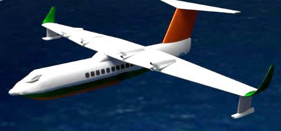
14 4 Initial Sizing 4.1 Preliminary Weights Figure 3: Conceptual Sketch. Once the requirements of an aircraft have been finalized, the first step and one could say the most important step in the preliminary portion of designing an aircraft is to calculate the preliminary weight of the aircraft. These weights represent a rough estimate of how much this aircraft will weigh, which will give foresight into the initial dimensions of the aircraft. Also, these calculations will help start the selection of what type of engine (Turboprop, Turbofan, Turbojet, etc.), wing configuration, empennage configuration, and other configurations. As mentioned before, the Sea Duck is being designed to accomplish three different types of missions (passenger, cargo, and maritime). Since the aircraft has three different missions, there had to be three different preliminary weight calculations because each mission had different payloads, cruise lengths, and loiter times to take into account. By the use of Microsoft Excel the group programmed each mission s own weight calculation, which can be viewed in Appendix I. Table 1 shows each mission s calculated takeoff weight. The passenger mission used the 1000 nautical mile range with 48 passengers and the cargo mission used the 500 nautical mile range with a 5,000 lb pay- 13


15 load. Then the maritime mission was calculated using two different ranges, one with a total of 500 nautical miles traversed and the other only 250 nautical miles with both tests using a payload of 3,000 lbs. In these calculations, the choice of an engine type had to be made, at this time the team remained undecided between a turbofan or turboprop. The decision of the propulsion system will be discussed later in this report. Therefore, two sets of weight calculations were generated. Also note that each mission operates at a speed of 250 knots except for the maritime mission, which loiters at 150 knots. Table 2: Mission s Preliminary Takeoff Weight Calculations. Also, Table 3 shows the results for the trade study the group ran to see how the takeoff weights are affected when changing the minimum amount of passengers (20+3 crew) to the maximum amount of passengers (48+3 crew) for a turbofan and turboprop. As expected the more passengers the heavier the aircraft. This trade study was also conducted to see the difference between the two engine types that were selected. Also, the trade study was run to gather a comparison between the two other missions if the team would choose to carry more than the minimum amount of passengers. Table 3: Takeoff Weight per Amount of Passengers and Crew. 14

16 4.2 Thrust-to-Weight and Wing Loading To find our thrust-to-weight value we used the formulas provided by Raymer in Aircraft Design: A Conceptual Approach. We used Thrust Matching technique and a statistical approach provided in the text. Once these values were ratioed back to takeoff, if necessary, the largest value is selected. With this thrust-to-weight value we can then determine the wing loading for our aircraft. To do this we used equations provided by Raymer to analyze the wing loading at several important flight parameters. For full details see Table 4. These different equations give us the wing loading values at these conditions. While calculating the wing loading for climb and glide our team realized our thrust-to-weight ratio was not greater than the desired climb gradient. We then solved for the thrust-to-weight that would meet this requirement and resolved the wing load equations effected by this change. Once all of the wing loadings have been solved the lowest is selected for our aircraft. Once all of the wing loadings were tabulated, typically the lowest is selected, but for our aircraft the wing loading at stall speed was omitted as outliers because this wing loading requires an exponential increase in wing size. Since the stall speed wing loadings were omitted from the choice, the team went with the next lowest wing loading. Table 4: Wing Loading. 4.3 Initial Wing Geometry To find our initial reference wing geometry we used the method described by Raymer in his text. We took our maximum preliminary weight as described in section 8.1 and divided that by the wing loading found in section 15

17 8.2. This gives us our reference wing area, which through the equations in Appendix III gives us the values. These values will allow our team to begin to design and optimize our airfoil. At this stage in the design our group has selected the NACA 4415 airfoil as our candidate airfoil. This airfoil has a maximum thickness of 15% which allows this airfoil to provide relatively high coefficients of lift (1.2 to 2.8 depending on Reynolds Number) at high angles of attack. This provides good STOL characteristics. These numbers are given with a clean wing, with no flaps or slats added. Moving forward in our analysis of our airfoils, different airfoils will be analyzed with the use of more sophisticated flaps and slats in mind. To meet our fuel efficiency criteria and loiter criteria we will also need our airfoil to have low drag. This points our research towards airfoils not traditionally used in STOL aircraft. Using computational fluid dynamics our team will analyze many airfoils and augmentation systems to optimize our wing for the broadest spectrum of mission criteria. Table 5: Initial Wing Geometry. 4.4 Revised Weights Again following the process Raymer has laid out, the last big step in initial sizing is a revised weight calculation. This weight calculation provides a 16
18 higher accuracy of what our aircraft will truly weigh. In Raymer s book the team followed section 6.3 to obtain the new weights (fuel, empty and takeoff) which takes the rubberized engine method and uses a statistical method with stricter parameters for empty weight fractions. Initially the team used this section exactly how it was laid out by Raymer (no fudge factor) but this method kept giving the team weights that were way to low for the amount of passengers, payload, and range. Therefore, the team found that this method could be adjusted through what Raymer called a fudge factor. A fudge factor takes an existing aircraft s empty weight to takeoff weight ratio that performs similar missions to the new aircraft being designed, the Beriev Be-200 was chosen for this aircraft. Then the Beriev Be-200 empty weight fraction will be divided by the weight fraction of our aircraft being designed, which this new number would be the fudge factor. This fudge factor will then be multiplied to the new statistical method in section 6.3 to find the empty weight fraction. This method to find the fudge factor can be seen in Appendix IV. Each Revised weight can be seen below in Tables 6 through 8. Table 6: Revised Weight Calculations for Passenger Max density. Table 7: Revised Weight Calculations for Passenger. 17


19 Table 8: Revised Weight Calculations for Cargo and Maritime. It can be seen that the most the Sea Duck will weigh at takeoff is 61,141 pounds, so the team made this mission the on-design objective. In other words, our aircraft is sized based on the maximum density, 1000 nmi mission and all other missions will use this airframe. 4.5 Revised Wing Geometry After the revised weights were calculated and chosen, a revised wing geometry needed to be created. The need for a revised wing geometry is driven by our aircraft s weight change, which led to affect mainly the wing area and wing span. The details can be seen in Table 9. Table 9: Revised Wing Parameters. 18

20 5 Configuration Selections 5.1 Fuselage Configuration The fuselage of our aircraft must accommodate our passenger payload, provide hydrodynamic stability and allow a means of stowing moderately sized cargo. It will need a minimum of two points of entry: one standard size door for passenger traffic and one larger door capable of accepting pallet sized cargo. The traditional cigar shape is still premiere when evaluating various shapes due to ease of construction, moment considerations and proven platforms. It must be long enough to house the cockpit, galley, passenger compartment and lavatory and wide enough for passenger cargo. We plan to have tandem seating on a modular platform either side of the walking isle and overhead bin storage on both port and starboard sides. To transform the passenger payload area to a cargo hold, the seats will be inserted on to tracks for ease of removal. This layout on the floor will coincide with rollers to maneuver pallet sized cargo fore and aft of the center of gravity of our plane. Figure 4: Fuselage Layout. 5.2 Wing Configuration Historically both flying boats and STOL aircraft utilize high-wing configurations. This provides excellent stability both in flight and on the water. High-wing configurations also give the pilot the visibility required for water landings and off-runway approaches. Additionally it provides increased propeller clearance over that of low-wing and mid-wing designs. Despite this our team is open to novel designs, therefore a mid-wing configuration was also considered briefly in our initial layout phase. 19

21 Mid-wing configurations are unusual for flying boats but not unheard of; the Beriev Be-103 uses this configuration. This layout normally provides the most efficient aerodynamics for a given aircraft. The major drawback of this design is the wing carry-through structure is mounted in the middle of the fuselage, interfering with valuable internal volume. This can be remedied but extreme measures must be used, i.e. Hansa Jet. For the reasons given above and the added problem of propulsion system placement after our design was changed to utilize turboprops, this design configuration was abandoned. A high-wing configuration is the natural choice for our aircraft. It provides stability and control under all mission conditions. Our engines and propellers are given adequate clearance for water landings and pilot visibility is improved for difficult water and off-runway landings. 5.3 Landing Gear Our design utilized a tricycle landing gear from its earliest conception onward. This configuration is widely used for passenger aircraft. It allows the aircraft to rest on a level plane for easy passenger boarding and cargo loadings. It also allows for the aircraft to be landed in very high crosswinds by facilitating a crab landing. The rear wheels for our aircraft mount flush with fuselage, much like the Grumman Albatross. They are placed just above the hull step to provide the most balance upon landing and ground maneuvers. Using historical data provided in Raymer the tire size was estimated to facilitate landing on all required surfaces. Table 10: Tire Size. 5.4 Tail Configuration The tail configurations being considered are the conventional, cruciform, and T-tail. From a structural perspective the conventional tail is most efficient. The control surfaces mate to the empennage such that controls are eas- 20
22 ily routed, thus saving weight, manufacturing costs, and maintenance time. Due to the placement of our engines, a conventional tail arrangement runs the risk of being blanketed during trimmed flight and low angles of attack. This causes a loss in control authority, to solve this a T-tail is considered. The T-tail offsets the interaction between lifting surfaces and disturbances in flow either due to wing wake or prop wash in trimmed flight. During high angles of attack T-tails encounter the same blanketing effect as conventional tails, making stall recovery very difficult. Different systems can be employed to alleviate this problem. One being seriously considered for our design is a boundary layer control system. The specifics of this system will be discussed in greater detail further in the paper. The T-tail arrangement has the added benefit of reducing the wetted area of the tail. The position of the horizontal stabilizer allows for a smaller size, but its distance above the centerline of the plane requires a sturdier vertical stabilizer which means extra weight. The cruciform tail is a compromise between the T-tail arrangement and the conventional tail. This configuration does not provide the reduction in wetted area offered by the T-tail but reduces the weight due to the lack of structural support required for the horizontal stabilizer. Early during the initial design our team was interested in employing a twin-boom tail arrangement. This would allow us to employ a rear loading ramp to quickly load and unload both cargo and passengers. Despite this advantage the weight penalty of twin-boom tails is significant and would likely hinder our STOL capabilities. This design did not receive further consideration. Both the T and Cruciform tail configurations are applicable options for our aircraft. A trade study will be performed to determine which is the superior choice based on our center of gravity, required moment, and aerodynamic considerations. 21


23 Figure 5: Empenage Layout. Table 11: Tail Sizing. 5.5 Engine Configuration The engine configurations being considered are turbofan or turboprop propulsion systems. Historically flying boats have used turboprop or piston driven engines. However, the request for proposal lays out aggressive takeoff parameters for the aircraft. Also, the requirements ask for the aircraft to have at least a 20 percent better fuel burn rate per passenger than the competitors. Therefore at first the team believed it would be best to use a turbofan. Turbofan engines can provide large amounts of thrust that would help meet the required takeoff distances especially when configured to provide a type of blown lifting surface (upper-surface blowing or blown flap). Also, turbofan engines are very efficient at subsonic speeds, hence their popularity with airliners. However, there are two problems that the team found with this configuration. The first problem is the risk of foreign object debris (water, dirt, etc) that could be sucked into the engine, causing engine failure. 22
. The efficiency of high-bypass ratio turbofans decreases significantly at this speed.")
24 The engines would most likely need to be placed above the wings, similar to the YC-14, which can cause maintenance to be more difficult. The biggest problem for the turbofan engine is our cruise speed is very low (250 knots). The efficiency of high-bypass ratio turbofans decreases significantly at this speed. This prompted our team to consider turboprop engines. Turboprop engines are more efficient in the velocity range considered for this design. The Turboprop configuration suffers from more restrictive clearance issues than turbofan engines, to solve this and increase our lift generated on takeoff our team is considering mounting the engines above the wings. This design would provide greater clearance for our propeller and will allow us to take advantage of augmented lift devices. There are many current turboprop and turboshaft engines that provide the necessary or even excess amounts of shaft horsepower we need to produce. TOPSIS analysis is utilized in engine selection; this process will be covered in greater detail further in the paper. Figure 6: Engine Layout. 23

25 6 Interior Layout 6.1 Passenger Compartment The request for proposal of our aircraft called for passenger seating from twenty to forty-nine single class passengers. The crew of our aircraft will consist of three members: Two pilots for each mission layout, while the third crew-member changes depending on the mission profile. Therefore, for Passenger mission a flight attendant will fill the third slot, a loadmaster for cargo missions, and an electronics officer for maritime surveillance missions. Seating arrangement for passenger mission was selected to maintain a single aisle layout. The configuration is a tandem seat on either side of the aisle, which spans 12 rows to total 48 seats. The chosen seat has a frame width of 18.1 inches coupled with an aisle width of 20 inches; the passenger compartment will span inches. We plan to employ a modular track system for both the seats and overhead bins for ease of removal during cargo missions. The functionality of this system would greatly expand the use of our design, allowing the seats to be removed easily for cargo transport. We elected to use overhead bins for passenger cargo with dimensions of 34 in x 34 in to provide the required 8 cubic feet of storage per person. Figure 7: Passenger Floor Plan. 24

26 Table 12: Fuselage Dimensions. 6.2 Cargo Layout The cargo area will be accessed by removal of the passenger components; both the seats and overhead storage bins. Access will be provided by an 88 x 91 inch cargo door located aft of the port side wing and maneuverability of the cargo will be made possible by rollers located in the floor. Anchor points will be positioned equally across the cargo hold which will allow proper restraint of the freight. These additions will facilitate efficient cargo loading, reducing the time our clients will lose to downtime. It should be noted that not all seats are required to be removed to accept cargo which would allow a hybrid payload. 25

27 Figure 8: Cargo Floor Plan. 26


28 7 Design Procedure 7.1 Wing Layout As discussed in section 9.2 the SCS-527 employs a high-wing configuration. To satisfy the STOL portion of our mission parameter a thick, well cambered wing is needed. This led our team to the NACA 63 and 65 series of airfoils. For comparison purposes we also selected the Selig class high-lift airfoil. Figure 9: NACA Based Wing. Figure 10: Selig Series Airfoil. Figure 11: Wing Layout. 27

29 Table 13: Wing Layout. Computational Fluid Dynamics was used to analyze our candidate wings, for more on these studies see Section Upon completion of these simulations our group chose the wing based on the NACA series of airfoils. This is predominantly chosen due to this airfoils superior lift-to-drag ratio. In short, this airfoil is more aerodynamically clean while cruising. To increase the lifting performance of our wings during takeoff a combination of sophisticated augmented lifting devices are being used. Essential to the STOL performance of our aircraft is the flaps being used and the flow over them. For our design we have selected double-slotted flaps that are positioned directly behind our props in order to ensure the flow over the flaps is properly energized to increase its low-speed performance. To further increase this performance our turboprops are positioned on top of the wings. Not only does this increase the propeller clearance of our design, 28

30 it also allows us to position the turbine exhaust to further energize the flow over the flaps. This method has been tested successfully by NASA for several decades and has been successfully implemented on the Boeing YC-14 and the Boeing C-17 Globemaster. It utilizes the coanda effect and the energized flow from the turbine exhaust to prevent flow separation over the flap and increase the low-speed lifting performance of our wings. To further increase the lifting performance of our wings slats are also being added. Table 14: Dimensions of Flaps and Ailerons. 7.2 Empennage Sizing The t-tail was selected for our final design for a few reasons. The position of the horizontal stabilizer out of disturbed flow and away from water spray is paramount.the stabilizer response should increase and issues with moisture on our lifting surfaces minimized by positioning both our wings high. The position of the tail plane on top allows minimum cover up during takeoff. Because of this we are able to design a smaller lifting surface required. Also contributing to this benefit is the longer moment arm provided by this design, which allows the control surfaces to reside in smooth flow. There is extra weight associated with the t-tail but structural support and rigidity are gained throughout the structure s region. An aspect that isn t very affordable to be overlooked is the aircraft s appeal.the t-tail is pleasing to the symmetry of the design which adds liveliness to the overall style of the aircraft. 7.3 Weight and Balance The team calculated the weight and balance for the Sea Duck using methodologies Raymer discusses in chapter 15 in his text. In this method the team found all the weights for the main components and some subcomponents of the aircraft. A datum was established at the nose. Therefore, the 29
 of the Sea Duck was found by taking the sum of the moments divided by the sum of the weights, which the position of the cg is")
31 length from the nose to the location where the weight of each component is acting was found, which then led to calculating the moment about the nose that is generated by each weight. Once all of the moments were calculated the center of gravity (cg) of the Sea Duck was found by taking the sum of the moments divided by the sum of the weights, which the position of the cg is slightly behind half of the aircrafts length. See Table 15 below. Table 15: Weight and Balance. 30


32 7.4 Hull Design Preliminary Design The preliminary hull design started with research. The group was not familiar with hull design, so it was going to be the biggest topic that would involve a learning curve on figuring out what was needed to design a hull. Once the group had better understanding in hull design, the next step was to start using Catia V5 to get CAD models of different preliminary hull designs. The first preliminary design can be seen below in Figure 12. This design was established to have a very basic shape, which it was based off the looks of a speed boat hull. The design is based on this because these types of hulls have high lift in the water, which in context to our aircraft will help get the Sea Duck on top of the bow wave. Since preliminary design 1 was a simple platform for upcoming designs, it would not be the best hull design to use for the final design. However, preliminary hull design 2 in Figure 13 has the best characteristics thus far for a choice for the hull design. Preliminary Design 2 has the characteristic of a V-shape hull like design 1, but design 2 added sister-keelsons, and spray rails. These additions to the design will help the hydrodynamic properties than the first design. Figure 12: Prelim Hull Design 1. Figure 13: Prelim Hull Design 2. 31
33 The parameters of the above hull designs were derived from preliminary dimensions based on our initial layout. These parameters listed below define the bottom width of the hull or beam. The step which is where the aircraft will pivot when on plane during takeoff is located just aft of the CG. Other features are derivatives of high speed characteristics of speed boats. One thing to note is the thickness of the hull which will be reinforced to sustain the weight of the aircraft during the landing transition from air to water. Table 16: Preliminary Hull Dimensions Revised Hull Design After the team dimensioned the aircraft and calculated the weight and balance, the revised hull design could be completed. The updated beam, length to step, forebody flat, step height, and thickness can be seen in Table 17 below. Table 17: Revised Hull Design. In the revised hull design, the design is a flared hull where the first flare to the double keelson is large to help break up the bow wave into smaller vortices; this will help decrease the water takeoff distance. The double keelsons can be compared to a vortex generator or a notch on a wing. The second flare, acting as a spray skirt, is not as drastic as the first flare but will force the water outward and away from our propellers. Even with this second flare a possibility of upward water spray still exists. Therefore, the aircraft may need two additional spray skirts on each side of the cockpit and at the main landing gear to help prevent excessive spray. In Gudmundssons book, there is an empirical formula that was used to calculate the maximum wave height the Sea Duck could handle, which was based on the takeoff gross weight. The maximum wave height the Sea Duck 32

34 can handle was 5 feet, which is greater than sea state 3, which is what the RFP asked for. Mentioned before the team was initially using Catia V5 to model the hull/fuselage. However, the team began having complications with Catia V5, forcing the group to transfer the design into Solidworks for completion and CFD analysis. This design can be seen below. Figure 14: Revised Hull Design 7.5 Augmented Lifting Devices Boundary Layer Control In addition to the previously mentioned augmented lifting devices, and the flaps and slats, our team has researched boundary layer control systems. These systems direct compressed air over the control surfaces and flaps on the aircraft to increase their effectiveness, especially at low speeds. Many different methods exist to compress the air for this purpose; bleed air from the engines can be routed for this purpose or as in our case, a separate turbine can be dedicated to this task. After the team evaluated our takeoff performance the necessity of this system is in question. As will be shown later that our aircraft performed admirably at all takeoff criterions without this system being accounted for. A possible future trade study could determine what combination of engine thrust and boundary layer control system generates both superior takeoff performance and fuel economy. 33

35 Marginally independent of takeoff performance boundary layer control systems have a number of benefits for our design. First, the compressed air can be routed to the control surfaces of our aircraft, greatly increasing their control authority at lower speeds. Second, this system can reduce the risk of our aircrafts t-tail being blanketed during high angle of attack maneuvers. Figure 15: Boundary Layer Control Engine: LHTEC t Hydrofoil Early in the research stage of this project our team discovered post World War Two articles describing the takeoff performance of flying boats being increased with the addition of hydrofoils. These hydrofoils are designed to generate a significant amount of lift at substantially lower speeds. Thus, lifting the hull from the water and greatly reducing the hydrodynamic drag on the hull and increasing takeoff performance. After takeoff the hydrofoil 34


36 retracts into the hull to negate its aerodynamic drag. As an aside the team designed two hydrofoils and tested them using computational fluid dynamics to see if any great benefit could be found. Unfortunately, after several tests none of the hydrofoils performed to expectations; most only lifted the estimated weight of the hydrofoil itself, associated systems, support structure, hydraulics, hull doors, etc. Figure 16: Computational Fluid Dynamics of Hydrofoil. Figure 17: Hydrofoil Based on NACA 65 Series Airfoil. 35

37 7.6 Stability Airborne To provide necessary stability methods used by Raymer were employed to size the control surfaces. These methods relied heavily on historical data to calculate these values. The results are displayed in Table 18 below. These control surfaces have a moment arm of feet, measured from the mean aerodynamic chord of the wing to the mean aerodynamic chord of the control surfaces. Table 18: Rudder and Elevator Dimensions Waterborne The team knew that stability in the water would be a crucial criterion to test because if the aircraft s buoyant force was not sufficient the aircraft would sink, obviously not a desired outcome. Also, if the distance between the metacentric height to the CG of the hull was less than the distance between the Center of Buoyancy and CG than the hull would be unstable without any aids. Due to the complex shape of the aircraft s hull, the team used simple geometry to approximate. The hull was assumed to be triangular in shape (giving it a smaller volume than in reality and thus less buoyant force) with the dimensions that were set forth in the fuselage length and the hull design dimensions. Once that assumption was made, the team used Archimedes principle to find the amount of volume displaced in fresh water when the buoyancy force was equal to the Maximum Takeoff Weight (MTOW), which was then increased so that the buoyancy force would be large enough to hold the aircraft s Max Takeoff Weight. After the volume displaced was found, the height of the waterline was calculated, which came out to be 3.3 feet from the bottom of the hull. After the height of the water line and the volume displaced was found, the stability of the hull was then tested through basic fluid statics knowledge. All the equations used can be seen in Appendix The stability results of the hull came back that the 36

38 hull itself was unstable. This was to be expected as no additional stability aids were included in this calculation. Therefore, the team used the Appendix C3 from the book General Aviation Aircraft Design: Applied Methods and Procedures by Gudmundsson to find what the metacentric height would be with wing tip floats. The results showed that with wing tip floats, the distance from the metacentric height to the center of gravity was larger than the distance between center of buoyancy and CG, which means the aircraft would be stable in the water. Once the team concluded we needed wing tip floats to stabilize the aircraft we placed them four degrees from center of the hull and the water line to the bottom of the wing tip float, which came out to be placed 53 feet from the center of the aircraft and 3.76 feet above the water line. Figure 18: Dimensions of Wingtip Floats 7.7 Computational Fluid Dynamics Computational fluid dynamics is employed by our team to analyze the candidate airfoils. All CFD for this project is being run on Solidworks 2016 Flow Simulation software. The goal of these studies is to determine realistic performances of our designed airfoils in true flying conditions. Using the CFD software our group is able to simulate the wing operating under different conditions at different angles of attack. 37


39 Figure 19: NACA 65 Series Wing at High Angle of Attack Figure 20: Flow Separation at High Angle of Attack. Figure 20 illustrates the capabilities of CFD analysis; this image shows the beginnings of flow separation at the trailing edge of our airfoil during takeoff-climb. The angle of attack during this maneuver is considerably more aggressive for a STOL aircraft, thus our team ran these simulations to ascertain the manner of flow under these extreme conditions. These simulations informed our decisions regarding augmented lifting devices. In addition to using CFD to analyze the extreme cases our wing will encounter, it was also used to analyze the performance of the wing. An extensive series of simulations were run at cruise conditions (250 knots at 20,000 feet), which the angle of attack of the wing was changed each simulation to gather the pertinent aerodynamic coefficients. The results can be seen below. Figure 21: Coefficient of Lift vs. Angle of Attack Figure 22: Coefficient of Drag vs. Angle of Attack. 38
40 Figure 23: Coefficient of Lift vs. The Coefficient of Drag Figure 23 is of special importance, this graph allows us to determine our best lift-to-drag ratio for our airfoil. To find the maximum point, a line tangent to the curve is ran from the origin to the curve. For our wing design this point coincides with our airfoil having a zero angle of incidence. This led the team to alter the design slightly from the intended one degree angle of incidence. In addition to using CFD to analyze our wings it was also used to gather information about our final hull design. With these techniques now established our team would use this information in future trade studies to design 39

41 our hull for better hydro and aerodynamics. This would not only increase our capabilities in the water but also reduce our fuel consumption through improved aerodynamics. Figure 24: Velocity of Water as it Interacts with the Hull 40

42 8 Aircraft 3-Views Figure 25: Aircraft 3-Views. 41

43 9 Propulsion System Layout, Integration and Trade Study 9.1 Powerplant Selection When choosing the engine for the aircraft the team found five initial candidate engines. Each of the candidate engines contained attributes we selected as critical to our design. To ascertain the best engine for our design the team programmed a TOPSIS (The Technique for Order of Preference by Similarity to Ideal Solution) design matrix to select one of the five engines. Our team selected three parameters used to compare each engine, which were power to weight ratio, specific fuel consumption, and acquisition cost. This matrix can be seen below in Table 19. Table 19: Engine Selection Data. After the parameters were set the matrix was normalized for each parameter, which then was a multiplier to the weight criteria decided by the team. The weight criteria can be seen in Appendix V. Once weighted there was an ideal engine made, which served as a baseline to compare our initial five candidate engines.from this step, the TOPSIS analysis ran the final decision matrix in Table 20, which shows that the best engine was the Honeywell T-55-L-714A. 42
. Its combustion chamber is an annular reverse-flow with 28 fuel burners. Also, the turbine consists of four stages.")
44 Table 20: Engine Selection Final Results. This engine has seven axial compressor stages and a single centrifugal compressor with an overall pressure ratio of 9.3. As well as, the engine has a mass flow of (lb/s). Its combustion chamber is an annular reverse-flow with 28 fuel burners. Also, the turbine consists of four stages. Where the first two stages are connected to the High Pressure Shaft, which is used to extract the energy to turn the compressor stages, and the last two stages are connected to the Low pressure shaft. Since this engine can be either a turboshaft or a turboprop engine, a two stage helical reduction gearbox will be used to reduce the rpm for the Dowty R414 propeller our team has selected. 43

45 Figure 26: Honeywell T-55-L-714A. 9.2 Powerplant Placement The engine placement on our aircraft was driven by three main considerations.first, the engines must be placed to provide adequate propeller clearance. The RFP calls for our aircraft to be able to navigate Sea State 3 conditions (0.5 to 1.25 meters), to reduce the wear on the engines and propellers we needed to mount the propulsion system well above possible wave-strikes. Second, our group wanted to place our propulsion system in a location to provide the greatest lifting advantage through augmented lifting solutions. Third; ease of maintenance, the Sea Duck is intended to be capable of serve and operate from rural communities with rudimentary service facilities. Our team understands these needs and strives to provide an aircraft capable of these needs Podded One possible solution would be to mount the engines in pods above the wings. This configuration, inspired by the Honda Jet would raise the turbines far from any foreign object debris or possible wave strike. This installation would meet the first requirement but presents problems for the last two. Mounting the engines in pods is not ideal for utilizing the engines for added lift. This configuration also hampers field maintenance by lifting the engines further off the wings. Other problems with this design include the added drag of the mounting pylons for the nacelles and the necessity of lengthening 44
46 the T-tail to account for the raising of the engines. This is needed to prevent blanketing by the propeller wash which occurs at a lower angle of attack with the engines podded above the wings Blended Another solution to the three criterion set by the team is to mount the turbines above the wings and blend them into the wing itself. This idea can be seen in the earliest design sketches, when the team was still pursuing a high-bypass turbofan propulsion system. This installation, similar in some respects to the Antonov An-32, keeps the engine mounted away from foreign object debris. Mounting the propulsion system in this manner is very conducive to its utilization for augmented lift. The flaps can still be blown by the propeller while if mounted sufficiently forward the exhaust of the turbine can be directed at the flaps for an added Upper-Surface Blowing effect. This configuration does pose certain problems for in-field maintenance. However, most of these problems are relevant only to major overhauls. For example, mounting the engines above the wings necessitates the use of an overhead crane for their removal. With all these factors taken into consideration our team feels mounting the engines in this fashion is best for the overall performance of our design. 45

47 10 Cockpit Layout 10.1 Cockpit Instrumentation In the RFP, it asks that the aircraft to be able to fly in VFR and IFR conditions. Therefore, the team decided to use the Garmin G-5000 to accomplish this task. The G-5000 is a glass cockpit where the four monitors are all touchscreen, which declutters the cockpit, making the control panel more user friendly. Also, each display can be a multifunction display, which would allow for example airway charts on one half and approach plates on the other. This system uses Synthetic Vision Technology (SVT) to use the system s terrain alerting database, which depicts the ground and water features, obstacles, and traffic in proximity of our aircraft. As well as, the SVT can depict all of this in IFR or nighttime VFR conditions. Figure 27: Cockpit and Avionics Layout. 46
48 11 Performance Verification 11.1 From Requirements The required minimum cruise speed was set at 250 knots in the RFP. Building a function in MATLAB we calculated operation points for our designed aircraft and plotted them. Using Anderson Intro to flight, we calculated aerodynamic parameters and set the velocity as an array from the stall speed of 82 ft/s to 1000 ft/s. Entering the thrust available, take-off weight, C D0, altitude density,and Coefficients of lift and drag we were able to calculate a power required graph to determine a few of our operating points. Below is the power required curve as a function of velocity. By plotting our power available and power required simultaneously, we were able to display the intersection point which shows us our maximum velocity at 571 (ft/s) or a little over 338 knots. Figure 28: Power Required vs Free Stream Velocity. 47
49 Our next power required graph has the power divided into profile and induced power to total the net power required. Plotting the power required vs velocity shows us the component wise power with the profile power increasing and induced power decreasing. Which makes sense because as our plane gains speed the required profile power will increase with velocity, and the induced should decrease with decreasing angle of attack. Finding the minimum net power required will give us the velocity of maximum endurance or the speed at which we can stay in the air the longest, 157 ft/s or 93 knots. The other point of interest is where a tangent line drawn from the origin touches the net power curve. This point coincides with the intersection of profile power and induced power which is where equilibrium is reached, and the velocity for max range is obtained. At 207 ft/s or 123 knots, we can fly the furthest distance. Figure 29: Power Required vs Free Stream Velocity. Our final graph displays the rate of climb as a function of velocity. Again using Anderson, the rate of climb is determined to be the power available minus the power required divided by the weight. Confined to sea level, the 48
50 maximum of this function is calculated to be 158 ft/s or a climb rate of over 9000 ft/min. This value is rather large in comparison to cargo, transport and amphibious aircraft combined but foremost we are a STOL aircraft and when the power is needed we can produce it. Another consideration for our large power available is the condition that if we lose an engine on takeoff, we will still be able to climb out and fly on with the remaining three turboprops. Figure 30: Rate of Climb vs Free Stream Velocity Takeoff and Landing Distances In the request for proposal, takeoff and landing distances were the biggest tests needed to be proven for each mission. Using the methods provided by Raymer, the takeoff and landing distances for the three missions can be seen in the two tables below. The team designed this aircraft to hold 48 passengers. Therefore in the passenger takeoff and landing distances, the team calculated what the RFP wanted (20 passengers, with 250 nmi range), 49
51 but also the team wanted to show at 48 passengers the Sea Duck can still be a STOL aircraft. Due to the amount of available power, the landing distances for both 20 and 48 passengers came to be the same. As well as, the takeoff distance for 48 passengers is less because the climb angle needed to be as shallow as possible without going below the amount of thrust needed to take-off. Therefore, the aircraft needed to use more power to takeoff to get the minimum climb angle as close to the 20 passengers, which needed less power to takeoff to receive a minimum climb angle. Figure 31: Diagram of Takeoff. 50

52 Figure 32: Diagram of Landing. Table 21: Takeoff and Landing Distances for Passenger Mission RFP. 51


53 Table 22: Takeoff and Landing Distances for Passenger Mission RFP Continued. The RFP did not have as many tests for the cargo and maritime missions, but the takeoff and landing distances for both missions on dry pavement and on water can be seen below. The takeoff and landing equations can be seen in Appendix and Table 23: Takeoff and Landing Distances for Cargo and Maritime Mission RFP. 52
54 12 Systems and Subsystems Layout 12.1 Flight Controls There were two choices of flight controls that could be chosen between, which are traditional flight controls or fly by wire. Traditional flight controls are hydraulic controls that are actuated by pulleys and physical wires to move the control surfaces. Fly by wire flight controls sends signals to the control surfaces. The team chose fly by wire, because it would take out the response time of the control surfaces to respond to the pilot s commands. With quicker response time a faster maneuver could be performed if in a stalling situation, or when performing a low-cost maritime mission where the plane could possibly be in a constant bank and turn. 53

55 Figure 33: Flight Control System. 54
56 12.2 Fuel System After the Honeywell was chosen, the team read the full details in Jane s Aero-Engines and found the fuel system the engine uses. Therefore, the team went with this fuel system, which Jane s Aero-Engines says, L-714 uses the Chandler Evans FADEC type EMC-32T-2, consisting of hydraulic unit with gear type pump and DECU Electrical System The team researched and found that it is possible that an electrical system can take over what the hydraulic system is used to perform. This was already explained some in the flight controls section above. Due to this knowledge the team decided that the Sea Duck would only have the electrical system. The biggest reasoning behind this decision was the braking. Since the Sea Duck needed to be a STOL aircraft, landing in the distance required was a big concern. With an electrical system actuating the brakes the response is halved verse a hydraulic system Environmental System To further improve our aircrafts performance in rural areas without ground facilities our aircraft is equipped with an auxiliary power unit. The RE220 APU from Honeywell Aerospace was selected by the team. This APU will be used to start our main engines independent of ground facilities. To run our different environmental systems we will use bleed air from the main engines; this will power our cabin pressurization and other systems, such as avionics cooling. This bleed air is also used to provide anti-icing to our aircraft, in this system the air is uncooled and run through ducts to the wings flight surfaces, the tail surfaces and engine inlets. 55
57 13 Materials and Structures 13.1 Material Selection From the beginning of this project our team wanted this aircraft to use material chosen for their robustness and ease of maintenance. This aircraft is intended to be operated out of salt-water environments, one of the most corrosive environments seen by any aircraft. Servicing rural communities and island nations our aircraft cannot be guaranteed to have access to the facilities provided to most flying boats to counter this corrosion. To counter this corrosion with minimal operator input our team has chosen to use composite materials whenever possible for the exterior of our aircraft Hull The hull represents a major concern from a materials and structures standpoint. The hull must be sturdy enough to withstand the repeated impacts from water landings while maintaining lightness for overall performance. Our team decided a composite hull would serve our aircraft the best. The seamless construction of these hulls eliminates the separation of riveted panels commonly found in traditional aluminum hulls. This improves the overall water tightness of our aircraft and further limits scheduled maintenance. The advantages of the corrosion resistance of composites materials cannot be overstated. As previously mentioned this aircraft is designed to operate in and service local communities, far away from the normal support structures. The use of composite materials extends the life of the exterior components without the necessary post-operation cleanings given to amphibians operating out of well-equipped facilities Wings Our wings are supported by a carry through box that is placed on top of our fuselage. This carry through box supports many of our subsystems. Housed within the carry through box; over the fuselage, is the APU and the turbine that drives the Boundary Layer Control System. Adjacent to the APU and the turbine are our main fuel tanks. These bladder tanks hold cubic feet of Jet-A fuel. Our group plans to continue the use 56

58 of composite materials for the wings and control surfaces. This will further reduce corrosion of major components and reduce weight overall. Figure 34: Fuel Tank Layout Empennage Our group placed a trim tank in the empennage. This tank is also a bladder tank and has an internal volume of cubic feet. This tank is to trim the aircraft during flight instead of using the rear control surfaces that leads to a drag penalty. Continuing on with our theme, our group has chosen to use composites for the empennage. 57

59 14 Cost Estimation The DAPCA IV cost model was used for cost analysis for the production of our aircraft. This empirical model is a function of the aircraft s empty weight, speed and production run, and includes variables relating to engine parameters and bolt on costs such as avionics. Both the cost equations and hourly rates were adjusted for inflation by a magnitude of 7.1 percent based on the Consumer Price Index of their respective years. This model was developed based on large aircraft projects, but with some corrective factors can yield fairly accurate results.shown below is the distribution of cost with the DAPCA IV cost model. As you can see manufacturing has the largest portion with engineering a close second which seems reasonable considering we are designing an amphibious aircraft. Figure 35: Development Cost. 58
60 14.1 Certification Certification or airworthiness cost is included in the Flight Test Cost. This cost consists of planning, instrumentation, flight operations, and engineering and manufacturing support of flight testing. This expenditure is a necessity in verifying the capabilities of any aircraft. After writing a MAT- LAB function to calculate the DAPCA cost the Flight test cost output generated is $61 million to certify our 4 flight test aircraft. Development-support costs are non-recurring cost of the manufacturing support of RDT&E. In DAPCA these values are estimated directly and yielded a development and support cost of $181.2 million. The total cost of engineering is $861.6 million, and the tooling and manufacturing cost are $495.9 million, and $1.036 billion respectively Tooling and Manufacturing Considerations The internal structure of the plane is very similar to many existing aircraft. So the tooling effort should be well supported. Our test model ran financial calculations with a 60 production run at 1 a month. This would be doubtful as our plane is a midsize utility aircraft as well as amphibious. Increasing the budget in both time and cost. The choice of employing a current market power plant has benefits in brand recognition, parts availability and proven performance. Manufacturing would occur at various locations for large components and shipped by rail; Wings, engines, tail, airframe, winglets, etc. Assembly would occur at a central locations and be performed on an assembly line Profitability The investment cost factor is an estimation based on invested money you would apply to determine the purchase price of your aircraft for commercial sales. We chose a value of 20 percent increase over cost which totaled our purchase price to $56.2 Million/unit and production price at $46.83 Million. This estimated cost of aircraft for the consumer would put our break-even point at 10 months shy of our production run of 60 aircraft at a rate of 1 per month. Meaning we should profit the subsequent months to simulate a total net profit of $96.5 million dollars in the fifth year. 59
61 14.4 Maintenance Costs The main operation and maintenance costs are fuel, crew salaries and maintenance. Raymer states that for civilian aircraft fuel cost can be approximated to be about 38% of O&M cost, crew salaries around 24%, and maintenance about 25%. Operating a flying boat in a saltwater environment will assuredly increase these values by a margin of 10-20% with maintenance becoming the largest. 60

62 15 Final Design 61
63 16 Appendices 16.1 Acknowledgments Dr. Adeel Khalid: For Challenging us to always do better, and for unwavering support and patience for all of our questions MAMCO: For sponsoring our team with CATIA V5 Dr. Tom Fallon: For teaching us the foundation for aerospace engineering Chris Roper: For technical guidance in Solidworks and part time moral support Chris Shakal: For the CAD work of a very professional nacelle and props on GrabCAD Kurt Jacobson: For assisting and providing his facilities to make our model Ms. Christina Turner: For printing the poster and paper in a very short amount of time John Ware For assisting the team in finalizing the cosmetics of the aircraft. 62

64 16.2 Appendix I: Preliminary Weights Passenger Mission Table 24: Passenger Preliminary Weights. 63
65 Cargo Mission Table 25: Cargo Preliminary Weights. 64

66 Maritime Mission Table 26: Maritime Preliminary Weights. 65

67 16.3 Appendix II: Thrust-to-Weight ratio and Wing Loading Table 27: Wing Loading. 66

68 Table 28: Wing Loading. 67

69 Table 29: Wing Loading. 68
70 16.4 Appendix III: Initial Wing Geometry S = W 0 (W/S) (1) b = A S (2) C root = 2 S b(1 + λ) (3) C tip = λ C root (4) c = (2/3)C root(1 + λ + λ 2 ) (1 + λ) (1 + 2λ) Ȳ = (b/6) (1 + λ) (5) (6) 69

71 16.5 Appendix IV: Initial Sizing Table 30: Fudge Factor. 70

72 16.6 Appendix V: Propulsion Table 31: Engine Selection Weights Appendix VI: Performance Takeoff Distance 1 S G = ( ) ln( K T + K A Vf 2 ) (7) 2gK A K T + K A V 2 K A = i K T = ( T W ) µ (8) ρ 2(W/S) (µc L C D0 KC 2 L) (9) K = 1 πae (10) S R = 3V T O (11) S G,T otal = S G + S R (12) R = V 2 T R 0.2g (13) γ climb = arcsin( T D W ) (14) h T R = R(1 cos(γ climb )) (15) 71
Design Considerations for Stability: Civil Aircraft
 Design Considerations for Stability: Civil Aircraft From the discussion on aircraft behavior in a small disturbance, it is clear that both aircraft geometry and mass distribution are important in the design
The Airplane That Could!
 The Airplane That Could! Critical Design Review December 6 th, 2008 Haoyun Fu Suzanne Lessack Andrew McArthur Nicholas Rooney Jin Yan Yang Yang Agenda Criteria Preliminary Designs Down Selection Features
AIRCRAFT DESIGN SUBSONIC JET TRANSPORT
 AIRCRAFT DESIGN SUBSONIC JET TRANSPORT Analyzed by: Jin Mok Professor: Dr. R.H. Liebeck Date: June 6, 2014 1 Abstract The purpose of this report is to design the results of a given specification and to
Revisiting the Calculations of the Aerodynamic Lift Generated over the Fuselage of the Lockheed Constellation
 Eleventh LACCEI Latin American and Caribbean Conference for Engineering and Technology (LACCEI 2013) International Competition of Student Posters and Paper, August 14-16, 2013 Cancun, Mexico. Revisiting
Reducing Landing Distance
 Reducing Landing Distance I've been wondering about thrust reversers, how many kinds are there and which are the most effective? I am having a debate as to whether airplane engines reverse, or does something
Aircraft Design in a Nutshell
 Dieter Scholz Aircraft Design in a Nutshell Based on the Aircraft Design Lecture Notes 1 Introduction The task of aircraft design in the practical sense is to supply the "geometrical description of a new
1.1 REMOTELY PILOTED AIRCRAFTS
 CHAPTER 1 1.1 REMOTELY PILOTED AIRCRAFTS Remotely Piloted aircrafts or RC Aircrafts are small model radiocontrolled airplanes that fly using electric motor, gas powered IC engines or small model jet engines.
APR Performance APR004 Wing Profile CFD Analysis NOTES AND IMAGES
 APR Performance APR004 Wing Profile CFD Analysis NOTES AND IMAGES Andrew Brilliant FXMD Aerodynamics Japan Office Document number: JP. AMB.11.6.17.002 Last revision: JP. AMB.11.6.24.003 Purpose This document
Appenidix E: Freewing MAE UAV analysis
 Appenidix E: Freewing MAE UAV analysis The vehicle summary is presented in the form of plots and descriptive text. Two alternative mission altitudes were analyzed and both meet the desired mission duration.
CONCEPTUAL DESIGN OF UTM 4-SEATER HELICOPTER. Mohd Shariff Ammoo 1 Mohd Idham Mohd Nayan 1 Mohd Nasir Hussain 2
 CONCEPTUAL DESIGN OF UTM 4-SEATER HELICOPTER Mohd Shariff Ammoo 1 Mohd Idham Mohd Nayan 1 Mohd Nasir Hussain 2 1 Department of Aeronautics Faculty of Mechanical Engineering Universiti Teknologi Malaysia
Aircraft Design Conceptual Design
 Université de Liège Département d Aérospatiale et de Mécanique Aircraft Design Conceptual Design Ludovic Noels Computational & Multiscale Mechanics of Materials CM3 http://www.ltas-cm3.ulg.ac.be/ Chemin
ECO-CARGO AIRCRAFT. ISSN: International Journal of Science, Engineering and Technology Research (IJSETR) Volume 1, Issue 2, August 2012
 Volume 1, Issue 2, August 2012") ECO-CARGO AIRCRAFT Vikrant Goyal, Pankhuri Arora Abstract- The evolution in aircraft industry has brought to us many new aircraft designs. Each and every new design is a step towards a greener tomorrow.
ECO-CARGO AIRCRAFT Vikrant Goyal, Pankhuri Arora Abstract- The evolution in aircraft industry has brought to us many new aircraft designs. Each and every new design is a step towards a greener tomorrow.
Chapter 10 Parametric Studies
 Chapter 10 Parametric Studies 10.1. Introduction The emergence of the next-generation high-capacity commercial transports [51 and 52] provides an excellent opportunity to demonstrate the capability of
Aircraft Design: A Systems Engineering Approach, M. Sadraey, Wiley, 2012 Chapter 11 Aircraft Weight Distribution Tables
 Aircraft Design: A Systems Engineering Approach, M. Sadraey, Wiley, 01 Chapter 11 Aircraft Weight Distribution Tables No Component group Elements Weight X cg Y cg Z cg 1 Wing 1.1. Wing main structure 1..
Systems Group (Summer 2012) 4 th Year (B.Eng) Aerospace Engineering Candidate Carleton University, Ottawa,Canada Mail:
 4 th Year (B.Eng) Aerospace Engineering Candidate Carleton University, Ottawa,Canada Mail:") Memo Airport2030_M_Family_Concepts_of_Box_Wing_12-08-10.pdf Date: 12-08-10 From: Sameer Ahmed Intern at Aero Aircraft Design and Systems Group (Summer 2012) 4 th Year (B.Eng) Aerospace Engineering Candidate
Memo Airport2030_M_Family_Concepts_of_Box_Wing_12-08-10.pdf Date: 12-08-10 From: Sameer Ahmed Intern at Aero Aircraft Design and Systems Group (Summer 2012) 4 th Year (B.Eng) Aerospace Engineering Candidate
Performance means how fast will it go? How fast will it climb? How quickly it will take-off and land? How far it will go?
 Performance Concepts Speaker: Randall L. Brookhiser Performance means how fast will it go? How fast will it climb? How quickly it will take-off and land? How far it will go? Let s start with the phase
Aeronautical Engineering Design II Sizing Matrix and Carpet Plots. Prof. Dr. Serkan Özgen Dept. Aerospace Engineering Spring 2014
 Aeronautical Engineering Design II Sizing Matrix and Carpet Plots Prof. Dr. Serkan Özgen Dept. Aerospace Engineering Spring 2014 Empty weight estimation and refined sizing Empty weight of the airplane
Part II. HISTORICAL AND ENGINEERING ANALYSIS OF AIRSHIP PLAN-AND- DESIGN AND SERVICE DECISIONS
 CONTENTS MONOGRAPHER S FOREWORD DEFENITIONS, SYMBOLS, ABBREVIATIONS, AND INDICES Part I. LAWS AND RULES OF AEROSTATIC FLIGHT PRINCIPLE Chapter 1. AIRCRAFT FLIGHT PRINCIPLE 1.1 Flight Principle Classification
INVESTIGATION OF ICING EFFECTS ON AERODYNAMIC CHARACTERISTICS OF AIRCRAFT AT TSAGI
 INVESTIGATION OF ICING EFFECTS ON AERODYNAMIC CHARACTERISTICS OF AIRCRAFT AT TSAGI Andreev G.T., Bogatyrev V.V. Central AeroHydrodynamic Institute (TsAGI) Abstract Investigation of icing effects on aerodynamic
INDIAN INSTITUTE OF TECHNOLOGY KANPUR
 INDIAN INSTITUTE OF TECHNOLOGY KANPUR INDIAN INSTITUTE OF TECHNOLOGY KANPUR Removable, Low Noise, High Speed Tip Shape Tractor Configuration, Cant angle, Low Maintainence Hingelesss, Good Manoeuverability,
High aspect ratio for high endurance. Mechanical simplicity. Low empty weight. STOVL or STOL capability. And for the propulsion system:
 Idealized tilt-thrust (U) All of the UAV options that we've been able to analyze suffer from some deficiency. A diesel, fixed-wing UAV could possibly satisfy the range and endurance objectives, but integration
AE 451 Aeronautical Engineering Design Final Examination. Instructor: Prof. Dr. Serkan ÖZGEN Date:
 Instructor: Prof. Dr. Serkan ÖZGEN Date: 11.01.2012 1. a) (8 pts) In what aspects an instantaneous turn performance is different from sustained turn? b) (8 pts) A low wing loading will always increase
Aircraft Design: A Systems Engineering Approach, M. Sadraey, Wiley, 2012 Chapter 3 Aircraft Conceptual Design. Tables
 Aircraft Design: A Systems Engineering Approach, M. Sadraey, Wiley, 2012 Chapter 3 Aircraft Conceptual Design Tables No Component Primary function Major areas of influence 1 Fuselage Payload accommodations
Chapter 10 Miscellaneous topics - 2 Lecture 39 Topics
 Chapter 10 Miscellaneous topics - 2 Lecture 39 Topics 10.3 Presentation of results 10.3.1 Presentation of results of a student project 10.3.2 A typical brochure 10.3 Presentation of results At the end
AERONAUTICAL ENGINEERING
 AERONAUTICAL ENGINEERING SHIBIN MOHAMED Asst. Professor Dept. of Mechanical Engineering Al Ameen Engineering College Al- Ameen Engg. College 1 Aerodynamics-Basics These fundamental basics first must be
CONCEPTUAL DESIGN OF ECOLOGICAL AIRCRAFT FOR COMMUTER AIR TRANSPORTATION
 26 TH INTERNATIONAL CONGRESS OF THE AERONAUTICAL SCIENCES CONCEPTUAL DESIGN OF ECOLOGICAL AIRCRAFT FOR COMMUTER AIR TRANSPORTATION Yasuhiro TANI, Tomoe YAYAMA, Jun-Ichiro HASHIMOTO and Shigeru ASO Department
Chapter 4 Estimation of wing loading and thrust loading - 10 Lecture 18 Topics
 Chapter 4 Estimation of wing loading and thrust loading - 10 Lecture 18 Topics 4.15.3 Characteristics of a typical turboprop engine 4.15.4 Characteristics of a typical turbofan engine 4.15.5 Characteristics
The Sonic Cruiser A Concept Analysis
 International Symposium "Aviation Technologies of the XXI Century: New Aircraft Concepts and Flight Simulation", 7-8 May 2002 Aviation Salon ILA-2002, Berlin The Sonic Cruiser A Concept Analysis Dr. Martin
SAE Baja - Drivetrain
 SAE Baja - Drivetrain By Ricardo Inzunza, Brandon Janca, Ryan Worden Team 11 Engineering Analysis Document Submitted towards partial fulfillment of the requirements for Mechanical Engineering Design I
PAC 750XL PAC 750XL PAC-750XL
 PAC 750XL The PAC 750XL combines a short take off and landing performance with a large load carrying capability. The PAC 750XL is a distinctive type. Its design philosophy is reflected in the aircraft's
Chapter 2 Lecture 5 Data collection and preliminary three-view drawing - 2 Topic
 Chapter 2 Lecture 5 Data collection and preliminary three-view dra - 2 Topic 2.3 Preliminary three-view dra Example 2.1 2.3 Preliminary three-view dra The preliminary three-view dra of the airplane gives
AE 451 Aeronautical Engineering Design I Propulsion and Fuel System Integration. Prof. Dr. Serkan Özgen Dept. Aerospace Engineering December 2017
 AE 451 Aeronautical Engineering Design I Propulsion and Fuel System Integration Prof. Dr. Serkan Özgen Dept. Aerospace Engineering December 2017 Propulsion system options 2 Propulsion system options 3
AE 451 Aeronautical Engineering Design I Estimation of Critical Performance Parameters. Prof. Dr. Serkan Özgen Dept. Aerospace Engineering Fall 2015
 AE 451 Aeronautical Engineering Design I Estimation of Critical Performance Parameters Prof. Dr. Serkan Özgen Dept. Aerospace Engineering Fall 2015 Airfoil selection The airfoil effects the cruise speed,
A SOLAR POWERED UAV. 1 Introduction. 2 Requirements specification
 A SOLAR POWERED UAV Students: R. al Amrani, R.T.J.P.A. Cloosen, R.A.J.M. van den Eijnde, D. Jong, A.W.S. Kaas, B.T.A. Klaver, M. Klein Heerenbrink, L. van Midden, P.P. Vet, C.J. Voesenek Project tutor:
Jay Gundlach AIAA EDUCATION SERIES. Manassas, Virginia. Joseph A. Schetz, Editor-in-Chief. Blacksburg, Virginia. Aurora Flight Sciences
 Jay Gundlach Aurora Flight Sciences Manassas, Virginia AIAA EDUCATION SERIES Joseph A. Schetz, Editor-in-Chief Virginia Polytechnic Institute and State University Blacksburg, Virginia Published by the
AIAA Foundation Undergraduate Team Aircraft Design Competition. RFP: Cruise Missile Carrier
 AIAA Foundation Undergraduate Team Aircraft Design Competition RFP: Cruise Missile Carrier 1999/2000 AIAA FOUNDATION Undergraduate Team Aircraft Design Competition I. RULES 1. All groups of three to ten
FLASHCARDS AIRCRAFT. Courtesy of the Air Safety Institute, a Division of the AOPA Foundation, and made possible by AOPA Services Corporation.
 AIRCRAFT FLASHCARDS Courtesy of the Air Safety Institute, a Division of the AOPA Foundation, and made possible by AOPA Services Corporation. Knowing your aircraft well is essential to safe flying. These
Flugzeugentwurf / Aircraft Design SS Part 35 points, 70 minutes, closed books. Prof. Dr.-Ing. Dieter Scholz, MSME. Date:
 DEPARTMENT FAHRZEUGTECHNIK UND FLUGZEUGBAU Flugzeugentwurf / Aircraft Design SS 2015 Duration of examination: 180 minutes Last Name: Matrikelnummer: First Name: Prof. Dr.-Ing. Dieter Scholz, MSME Date:
AIRCRAFT DESIGN MADE EASY. Basic Choices and Weights. By Chris Heintz
 AIRCRAFT DESIGN MADE EASY By Chris Heintz The following article, which is a first installement of a two-part article, describes a simple method for the preliminary design of an airplane of conventional
Innovating the future of disaster relief
 Innovating the future of disaster relief American Helicopter Society International 33rd Annual Student Design Competition Graduate Student Team Submission VEHICLE OVERVIEW FOUR VIEW DRAWING INTERNAL COMPONENTS
In this lecture... Prof. Bhaskar Roy, Prof. A M Pradeep, Department of Aerospace, IIT Bombay
 1 In this lecture... Intakes for powerplant Transport aircraft Military aircraft 2 Intakes Air intakes form the first component of all air breathing propulsion systems. The word Intake is normally used
XIV.C. Flight Principles Engine Inoperative
 XIV.C. Flight Principles Engine Inoperative References: FAA-H-8083-3; POH/AFM Objectives The student should develop knowledge of the elements related to single engine operation. Key Elements Elements Schedule
AIAA UNDERGRADUATE TEAM DESIGN COMPETITION PROPOSAL 2017
 TADPOLE AIAA UNDERGRADUATE TEAM DESIGN COMPETITION PROPOSAL 2017 Conceptual Design of TADPOLE Multi-Mission Amphibian MIDDLE EAST TECHNICAL UNIVERSITY 5-10-2017 Team Member AIAA Number Contact Details
Environmentally Focused Aircraft: Regional Aircraft Study
 Environmentally Focused Aircraft: Regional Aircraft Study Sid Banerjee Advanced Design Product Development Engineering, Aerospace Bombardier International Workshop on Aviation and Climate Change May 18-20,
Electric VTOL Aircraft
 Electric VTOL Aircraft Subscale Prototyping Overview Francesco Giannini fgiannini@aurora.aero 1 08 June 8 th, 2017 Contents Intro to Aurora Motivation & approach for the full-scale vehicle Technical challenges
General Dynamics F-16 Fighting Falcon
 General Dynamics F-16 Fighting Falcon http://www.globalsecurity.org/military/systems/aircraft/images/f-16c-19990601-f-0073c-007.jpg Adam Entsminger David Gallagher Will Graf AOE 4124 4/21/04 1 Outline
Humming Aerospace Version 9 Blade ti
 Humming Aerospace Version 9 Blade ti Designed By J Falk Hummingair LLC The Version 9 is a prototype carbon fiber intensive aircraft designed from the nose back to be much more efficient than existing aircraft
Preliminary Detailed Design Review
 Preliminary Detailed Design Review Project Review Project Status Timekeeping and Setback Management Manufacturing techniques Drawing formats Design Features Phase Objectives Task Assignment Justification
Airframes Instructor Training Manual. Chapter 6 UNDERCARRIAGE
 Learning Objectives Airframes Instructor Training Manual Chapter 6 UNDERCARRIAGE 1. The purpose of this chapter is to discuss in more detail the last of the Four Major Components the Undercarriage (or
B737 Performance. Takeoff & Landing. Last Rev: 02/06/2004
 B737 Performance Takeoff & Landing Last Rev: 02/06/2004 Takeoff Performance Takeoff Performance Basics Definitions: Runway Takeoff Distances Definitions: Takeoff Speeds JAR 25 Requirements Engine failure
New Design Concept of Compound Helicopter
 New Design Concept of Compound Helicopter PRASETYO EDI, NUKMAN YUSOFF and AZNIJAR AHMAD YAZID Department of Engineering Design & Manufacture, Faculty of Engineering, University of Malaya, 50603 Kuala Lumpur,
10th Australian International Aerospace Congress
 AUSTRALIAN INTERNATIONAL AEROSPACE CONGRESS Paper presented at the 10th Australian International Aerospace Congress incorporating the 14th National Space Engineering Symposium 2003 29 July 1 August 2003
AE 452 Aeronautical Engineering Design II Installed Engine Performance. Prof. Dr. Serkan Özgen Dept. Aerospace Engineering March 2016
 AE 452 Aeronautical Engineering Design II Installed Engine Performance Prof. Dr. Serkan Özgen Dept. Aerospace Engineering March 2016 Propulsion 2 Propulsion F = ma = m V = ρv o S V V o ; thrust, P t =
CHAPTER 10. WEIGHT AND BALANCE
 9/27/01 AC 43.13-1B CHG 1 CHAPTER 10. WEIGHT AND BALANCE SECTION 1 TERMINOLOGY 10-1. GENERAL. The removal or addition of equipment results in changes to the center of gravity (c.g.). The empty weight of
Chapter 4 Lecture 16. Engine characteristics 4. Topics. Chapter IV
 Chapter 4 Lecture 16 Engine characteristics 4 Topics 4.3.3 Characteristics of a typical turboprop engine 4.3.4 Characteristics of a typical turbofan engine 4.3.5 Characteristics of a typical turbojet engines
On-Demand Mobility Electric Propulsion Roadmap
 On-Demand Mobility Electric Propulsion Roadmap Mark Moore, ODM Senior Advisor NASA Langley Research Center EAA AirVenture, Oshkosh July 22, 2015 NASA Distributed Electric Propulsion Research Rapid, early
Weight & Balance. Let s Wait & Balance. Chapter Sixteen. Page P1. Excessive Weight and Structural Damage. Center of Gravity
 Page P1 Chapter Sixteen Weight & Balance Let s Wait & Balance Excessive Weight and Structural Damage 1. [P2/1/1] Airplanes are designed to be flown up to a specific maximum weight. A. landing B. gross
TEAM Four Critical Design Review. Kai Jian Cheong Richard B. Choroszucha* Lynn Lau Mathew Marcucci Jasmine Sadler Sapan Shah Chongyu Brian Wang
 TEAM Four Critical Design Review Kai Jian Cheong Richard B. Choroszucha* Lynn Lau Mathew Marcucci Jasmine Sadler Sapan Shah Chongyu Brian Wang 03.XII.2008 0.1 Abstract The purpose of this report is to
Electric Flight Potential and Limitations
 Electric Flight Potential and Limitations Energy Efficient Aircraft Configurations, Technologies and Concepts of Operation, Sao José dos Campos, 19 21 November 2013 Dr. Martin Hepperle DLR Institute of
This Flight Planning Guide is published for the purpose of providing specific information for evaluating the performance of the Cessna Corvalis TT.
 May 2010 TABLE OF CONTENTS This Flight Planning Guide is published for the purpose of providing specific information for evaluating the performance of the Cessna Corvalis TT. This guide is developed from
Prof. João Melo de Sousa Instituto Superior Técnico Aerospace & Applied Mechanics. Part B Acoustic Emissions 4 Airplane Noise Sources
 Prof. João Melo de Sousa Instituto Superior Técnico Aerospace & Applied Mechanics Part B Acoustic Emissions 4 Airplane Noise Sources The primary source of noise from an airplane is its propulsion system.
Welcome to Aerospace Engineering
 Welcome to Aerospace Engineering DESIGN-CENTERED INTRODUCTION TO AEROSPACE ENGINEERING Notes 5 Topics 1. Course Organization 2. Today's Dreams in Various Speed Ranges 3. Designing a Flight Vehicle: Route
Numerical Study on the Flow Characteristics of a Solenoid Valve for Industrial Applications
 Numerical Study on the Flow Characteristics of a Solenoid Valve for Industrial Applications TAEWOO KIM 1, SULMIN YANG 2, SANGMO KANG 3 1,2,4 Mechanical Engineering Dong-A University 840 Hadan 2 Dong, Saha-Gu,
Design of Ultralight Aircraft
 Design of Ultralight Aircraft Greece 2018 Main purpose of present study The purpose of this study is to design and develop a new aircraft that complies with the European ultra-light aircraft regulations
BELL HUEY II A daily workhorse with an expansive cabin providing multi-mission flexibility. TROOP TRANSPORT AND INSERTION
 BELL HUEY II A daily workhorse with an expansive cabin providing multi-mission flexibility. TROOP TRANSPORT AND INSERTION SEARCH AND RESCUE Look no further than the Bell Huey II for troop transport needs.
BELL HUEY II A daily workhorse with an expansive cabin providing multi-mission flexibility.
 BELL HUEY II A daily workhorse with an expansive cabin providing multi-mission flexibility. TROOP TRANSPORT AND INSERTION Look no further than the Bell Huey II for troop transport needs. With aft cabin
M I S S I O N A C C O M P L I S H E D
 M I S S I O N A C C O M P L I S H E D About Quest Aircraft Quest Aircraft Company is the manufacturer of the KODIAK, the next generation 10-seat utility turboprop. The KODIAK s rugged aluminum construction
Heavy Lifters Design Team. Virginia Polytechnic Institute and State University Free-Weight Final Report Spring 2007
 Heavy Lifters Design Team Virginia Polytechnic Institute and State University Free-Weight Final Report Spring 2007 The Heavy Lifters Leslie Mehl AIAA # 281854 Daniel Opipare AIAA #275371 Dzejna Mujezinovic
Evaluation of Novel Wing Design for UAV
 Evaluation of Novel Wing Design for UAV P. K. Bahumanyam 1 1 University of Alabama in Huntsville, Huntsville, AL, USA *Corresponding author: pkb0003@uah.edu Abstract: Viable design alternative for the
AN ADVANCED COUNTER-ROTATING DISK WING AIRCRAFT CONCEPT Program Update. Presented to NIAC By Carl Grant November 9th, 1999
 AN ADVANCED COUNTER-ROTATING DISK WING AIRCRAFT CONCEPT Program Update Presented to NIAC By Carl Grant November 9th, 1999 DIVERSITECH, INC. Phone: (513) 772-4447 Fax: (513) 772-4476 email: carl.grant@diversitechinc.com
Lockheed Martin. Team IDK Seung Soo Lee Ray Hernandez Chunyu PengHarshal Agarkar
 Lockheed Martin Team IDK Seung Soo Lee Ray Hernandez Chunyu PengHarshal Agarkar Abstract Lockheed Martin has developed several different kinds of unmanned aerial vehicles that undergo harsh forces when
Small Fixed Wing Aircraft Operational Weight and Balance Computations
 Small Fixed Wing Aircraft Operational Weight and Balance Computations Chapter 4 Weight and balance data allows the pilot to determine the loaded weight of the aircraft and determine whether or not the
JIM BEDE ADDS TWO HOMEBUILTS TO HIS LINE - THE BD-5J AND THE ALL NEW BD-6
 Newest homebuilt from Jim Bede is the BD-6, a single-place version of the popular four-place BD-4. A BD-6 FOR $2000 JIM BEDE ADDS TWO HOMEBUILTS TO HIS LINE - THE BD-5J AND THE ALL NEW BD-6 By WALTER SHELBOURNE
Backgrounder. The Boeing ecodemonstrator Program
 Backgrounder Boeing Commercial Airplanes P.O. Box 3707 MC 21-70 Seattle, Washington 98124-2207 www.boeing.com The Boeing ecodemonstrator Program To support the long-term sustainable growth of aviation,
A Game of Two: Airbus vs Boeing. The Big Guys. by Valerio Viti. Valerio Viti, AOE4984, Project #1, March 22nd, 2001
 A Game of Two: Airbus vs Boeing The Big Guys by Valerio Viti 1 Why do we Need More Airliners in the Next 20 Years? Both Boeing and Airbus agree that civil air transport will keep increasing at a steady
Introduction. Fuselage/Cockpit
 Introduction The Moravan Zlin 242L is a fully aerobatic 2 seat aircraft designed to perform all advanced flight maneuvers within an envelope of -3.5 to +6 Gs. Many military and civilian flight-training
HYDRAULIC ACTUATOR REPLACEMENT USING ELECTROMECHANICAL TECHNOLOGY
 HYDRAULIC ACTUATOR REPLACEMENT USING ELECTROMECHANICAL TECHNOLOGY SCOPE This white paper discusses several issues encountered by Lee Air with past projects that involved the replacement of Hydraulic Actuators
Preface. Acknowledgments. List of Tables. Nomenclature: organizations. Nomenclature: acronyms. Nomenclature: main symbols. Nomenclature: Greek symbols
 Contents Preface Acknowledgments List of Tables Nomenclature: organizations Nomenclature: acronyms Nomenclature: main symbols Nomenclature: Greek symbols Nomenclature: subscripts/superscripts Supplements
The new Raisbeck/Hartzell C90 Swept Blade Turbofan Propeller
 The new Raisbeck/Hartzell C90 Swept Blade Turbofan Propeller the new SWEPT BLADE TURBOFAN PROPELLER FOR THE ENTIRE KING AIR C90 FAMILY developed jointly by Raisbeck Engineering and Hartzell Propeller for
Karpuk Aircraft KR-1 Multi-Mission Amphibian
 Karpuk Aircraft KR-1 Multi-Mission Amphibian Response to 2016/2017 AIAA Foundation Graduate Individual Aircraft Design Competition Presented by Embry-Riddle Aeronautical University (Daytona Beach) Department
Sierra. R/STOL High Lift Systems. Toll Free LANCAIR. Sierra R/STOL High Lift System Benefits DURING APPROACH AND LANDING DURING TAKEOFF
 Sierra R/STOL High Lift Systems Complete R/STOL Systems include everything your aircraft needs for the utmost in performance. For expanded utility, increased safety and improved performance get off the
FIRST FLYING TECHNIQUES COCKPIT PREPARATION STARTUP TAXI
 1. Introduction FIRST FLYING TECHNIQUES COCKPIT PREPARATION STARTUP TAXI We aim to teach and demonstrate how to operate a general aviation aircraft and show some basic techniques and manoeuvres that every
SAE Mini BAJA: Suspension and Steering
 SAE Mini BAJA: Suspension and Steering By Zane Cross, Kyle Egan, Nick Garry, Trevor Hochhaus Team 11 Progress Report Submitted towards partial fulfillment of the requirements for Mechanical Engineering
The winner team will have the opportunity to perform a wind tunnel test campaign in the transonic/supersonic Wind tunnel at the VKI.
 Aircraft Design Competition Request for proposal (RFP) - High speed UAV Objectives: This RFP asks for an original UAV design capable of reaching, in less than 15 minutes, a given target located at 150
31 st Annual American Helicopter Society Student Design Competition: Graduate Submission
 Rotorcraft Adaptive and Morphing Structures Lab The Emperor UAV: Executive Summary George Jacobellis Alex Angilella Jean-Paul Reddinger Andrew Howard Matthew Misiorowski Michael Pontecorvo Jayanth Krishnamurthi
The following slideshow and talk were presented at the Uber Elevate Summit on April 25 th, The text included here is an approximate transcript
 The following slideshow and talk were presented at the Uber Elevate Summit on April 25 th, 2017. The text included here is an approximate transcript of the speech given by Jay Carter, founder and CEO of
PARAMETRIC MODELING OF AIRCRAFT FUEL SYSTEMS INTEGRATION IN RAPID
 PARAMETRIC MODELING OF AIRCRAFT FUEL SYSTEMS INTEGRATION IN RAPID Adrián Sabaté López and Raghu Chaitanya Munjulury Linköping University, Linköping, Sweden Keywords: Aircraft design, RAPID, Fuel systems,
Chapter 3: Aircraft Construction
 Chapter 3: Aircraft Construction p. 1-3 1. Aircraft Design, Certification, and Airworthiness 1.1. Replace the letters A, B, C, and D by the appropriate name of aircraft component A: B: C: D: E: 1.2. What
Remote Control Helicopter. Engineering Analysis Document
 Remote Control Helicopter By Abdul Aldulaimi, Travis Cole, David Cosio, Matt Finch, Jacob Ruechel, Randy Van Dusen Team 04 Engineering Analysis Document Submitted towards partial fulfillment of the requirements
Methodology for Distributed Electric Propulsion Aircraft Control Development with Simulation and Flight Demonstration
 1 Methodology for Distributed Electric Propulsion Aircraft Control Development with Simulation and Flight Demonstration Presented by: Jeff Freeman Empirical Systems Aerospace, Inc. jeff.freeman@esaero.com,
Powertrain Design for Hand- Launchable Long Endurance Unmanned Aerial Vehicles
 Powertrain Design for Hand- Launchable Long Endurance Unmanned Aerial Vehicles Stuart Boland Derek Keen 1 Justin Nelson Brian Taylor Nick Wagner Dr. Thomas Bradley 47 th AIAA/ASME/SAE/ASEE JPC Outline
Preliminary design of Aircraft Landing Gear Strut
 Preliminary design of Aircraft Landing Gear Strut Mainuddin A 1, 2 Abubakar Siddiq S 2, Mohammed Farhaan Shaikh 3, Abdul Falah B 4, Jagadeesh B 5 1,2,3,4 Student, Department of Aeronautical Engineering,
TAKEOFF PERFORMANCE ground roll
 TAKEOFF PERFORMANCE An airplane is motionless at the end of a runway. This is denoted by location O. The pilot releases the brakes and pushes the throttle to maximum takeoff power, and the airplane accelerates
EAS 4700 Aerospace Design 1
 EAS 4700 Aerospace Design 1 Prof. P.M. Sforza University of Florida Commercial Airplane Design 1 1.Mission specification and market survey Number of passengers: classes of service Range: domestic or international
JetBiz. Six and Eight Passenger Business Jets
 JetBiz Presents the Six and Eight Passenger Business Jets In response to the 2016 2017 AIAA Foundation Undergraduate Team Aircraft Design Competition Request for Proposal Presented by California State
BELL 206L4 A reliable multi-mission capable helicopter with low operating costs.
 BELL 206L4 A reliable multi-mission capable helicopter with low operating costs. CORPORATE The Bell 206L4 is designed to be the ideal flying workplace. It comfortably seats up to six passengers with one
Initial / Recurrent Ground Take-Home Self-Test: The Beechcraft 58 Baron Systems, Components and Procedures
 Initial / Recurrent Ground Take-Home Self-Test: The Beechcraft 58 Baron Systems, Components and Procedures Flight Express, Inc. This take-home self-test partially satisfies the recurrent ground training
Air Buzz. 32nd Annual AHS International Student Design Competition
 Air Buzz 32nd Annual AHS International Student Design Competition Faculty Advisor: Dr. Daniel Schrage, Daniel.Schrage@aerospace.gatech.edu Ezgi Selin Akdemir esakdemir@gmail.com Undergraduate Middle East
CHAPTER 3. A journey of a thousand miles begins with a single step. Confucius
 CHAPTER 3 INTRODUCTION... 3-1 TAIL WHEELS... 3-2 TAILDRAGGER ADVANTAGES... 3-3 TAILDRAGGER DISADVANTAGES... 3-3 CONTROLS... 3-4 TAXI AERODYNAMICS... 3-5 GROUND OPERATIONS... 3-7 INTRODUCTION Hangar flying,
Flight Test Evaluation of C-130H Aircraft Performance with NP2000 Propellers
 Flight Test Evaluation of C-130H Aircraft Performance with NP2000 Propellers Lance Bays Lockheed Martin - C-130 Flight Sciences Telephone: (770) 494-8341 E-Mail: lance.bays@lmco.com Introduction Flight