2014 SAE AERO DESIGN EAST COMPETITION 10% Report
|
|
|
- Randall Mason
- 6 years ago
- Views:
Transcription
1 EML 4905 Senior Design Project A B.S. THESIS PREPARED IN PARTIAL FULFILLMENT OF THE REQUIREMENT FOR THE DEGREE OF BACHELOR OF SCIENCE IN MECHANICAL ENGINEERING 2014 SAE AERO DESIGN EAST COMPETITION 10% Report Claudia Eyzaguirre Fred Al-Abdala Luis Vallejos Advisor: Professor Dr. Andres Tremante October 28, 2013 This B.S. thesis is written in partial fulfillment of the requirements in EML The contents represent the opinion of the authors and not the Department of Mechanical and Materials Engineering.
2 Ethics Statement and Signatures The work submitted in this B.S. thesis is solely prepared by a team consisting of Fred Al- Abdala, Claudia Eyzaguirre, and Luis Vallejos and it is original. Excerpts from others work have been clearly identified, their work acknowledged within the text and listed in the list of references. All of the engineering drawings, computer programs, formulations, design work, prototype development and testing reported in this document are also original and prepared by the same team of students. Claudia Eyzaguirre Team Leader Fred Al-Abdala Team Member Luis Vallejos Team Member Dr. Andres Tremante Faculty Advisor ii
3 Contents Ethics Statement and Signatures... ii List of Figures... iv List of Tables... v Abstract... vi 1. Introduction Problem Statement Motivation Literature Survey Project Formulation Overview Project Objectives Design Specifications, Constraints and Other Considerations Design Alternatives Overview of Conceptual Designs Developed Wing Design Alternatives Airfoil Fuselage Empennage Design Alternatives Design Alternative A Design Alternative B Design Alternative C Feasibility Assessment Proposed Design Project Management Overview Breakdown of Work into Specific Tasks Breakdown of Responsibilities among Team Members Organization of Work and Timeline Analytical Analysis Kinematics Analysis iii
4 5.2 Wings Fuselage Major Components Structural Design Wings Fuselage Empennage Cost Analysis Prototype System Description Prototype Cost Analysis Tests on Prototype Conclusion Conclusion and Discussion Future Work References Appendices Appendix A: Competition Rules List of Figures Figure 1 First Flight by a Powered and Controlled Aircraft [4]... 2 Figure 2 Me 262, world first operational jet fighter [6]... 3 Figure 3 Aircraft major components [7]... 5 Figure 4 Wing Position Alternatives [8]... 6 Figure 5 Wing Shape Alternatives [9]... 8 Figure 6 Wing Components [10]... 9 Figure 7 Airfoil Shapes [11]... 9 Figure 8 Pressure Vectors and Flow Over a Camber Section [12] Figure 9 Forces Acting on Aircraft Figure 10 Empennage Components [13] Figure 11 Conventional Tail Design [14] Figure 12 T-Tail Design [14] Figure 13 H-Tail Design [14] Figure 14 Design Alternative A Figure 15 Design Alternative B Figure 16 Design Alternative C...16 Figure 17 Feasibility Assessment Figure 18 Project Timeline iv
5 Figure 19 Loading on beam Figure 20 Moment calculation Figure 21 Tapered wing ratio Figure 22 Warren Truss Figure 23 Product Hierarchy Figure 24 Structure of Wings and Fuselage Figure 25 Wing Structure Figure 26 Top view of wing Figure 27 Section cut of wing Figure 28 Fuselage Structure Figure 29 Front view of fuselage Figure 30 Fuselage top view Figure 31 Empennage design Figure 32 Design alternative Figure 33 Design alternative List of Tables Table 1 Design Alternative A Specifications Table 2 Design Alternative B Specifications Table 3 Design Alternative C Specifications...16 Table 4 Division on Workload Table 5 Cost Analysis Table 6 Prototype Cost Analysis v
6 Abstract The SAE Aero Design series provides engineering students with the opportunity to face a real-life engineering challenge by designing an aircraft based on a set of requirements. This competition not only focuses on technical knowledge in the aeronautics field, but also emphasizes in interpersonal communication, oral communication, and written skills by making a percentage of the score based in the design report and the oral presentation. Seventy- five university teams from different parts of the world will compete against each other putting their engineering, communication, and writing skills to the test. The competition will be held in Marietta, Georgia on April 11-13, The SAE Aero Design features three classes of competition; Regular, Advanced, and Micro. Our team will participate in the regular class. The objective of the regular class competition will be to design a remote controlled cargo aircraft and predict the aircraft s payload capacity while complying with the requirements of the competition. For the design of the aircraft, the team will conduct tradeoff studies on different design alternatives to select the best option based on cost, manufacturing time, loads, etc. To engage in current research in aerodynamics and to create a design that will have global acceptance, we will use current technology available to design the aircraft. The team will use a computational fluid dynamic (CFD) software to optimize the airplane s design to obtain optimal lift and reduce drag. Experimental validation of obtained CFD analysis will be done by using wind tunnel testing. The team will also perform structural optimization using finite element analysis through software such as SolidWorks and ANSYS. Other testing concepts include a test stand to analyze thrust of different motor and propeller combinations [1]. Through the research performed in this project, we wish to obtain results that can be used in future design of aircrafts to optimize efficiency. vi
7 1. Introduction 1.1 Problem Statement Annually, the Society of Automotive Engineers (SAE) hosts the Aero Design Series where engineering students are faced with the opportunity to take part in a reallife challenge by designing an aircraft based on set requirements. At this event our team will compete against university teams from different parts of the world such as Canada, Egypt, India, Brazil, Bangladesh, Poland and Mexico. The competition will be held in Marietta, Georgia on April 11-13, The SAE Aero Design features three classes of competition; Regular, Advanced, and Micro [1]. We will participate in the regular class. Based on the rules of the competition, each team is required to design a fully electric cargo airplane that will be able to complete a predetermined circuit carrying the predicted maximum payload while taking off and successfully landing within the specified parameters. The competition is divided into 3 phases as follows [1]: Phase 1: Technical report: Proposal describing the team s requirement compliance. Phase 2: Technical Presentation and Inspection. Phase 2A Payload Loading Demonstration (timed event during Oral Presentation). Phase 2B Payload Unloading Demonstration (timed event during Oral Presentation). Phase C Oral Presentation. Phase 3: Flight Competition Motivation The motivation behind this project is the aspiration to implement the theoretical knowledge acquired in different courses and put them to work in a real life scenario. The extensive research needed to design a successful aircraft will reinforce the concepts of aerodynamic, fluids mechanics, propulsion systems and mechanics of materials learned throughout our college experience. The development of a cost efficient, functional and unique design for our RC aircraft will be the final representation of the understanding of previously mentioned subjects. In addition, the passion the team members have towards 1

8 the aviation industry and the chance to represent Florida International University at a worldwide event motivates the team to be determined to excel in the competition. 1.3 Literature Survey Humanity s fascination with the idea of flying dates to over two thousand years ago with early records of aviation [2]. Early attempts in aviation included kites hot air balloons and gliders. The 1800s involved several attempts at lighter than air aircrafts, including the first fully controllable free-flight. At the same time, innovators experimented with heavier that air aircrafts. Several inventions and experiments where performed that contributed to the goal of creating a functioning aircraft. In 1900s, the Wright brothers built and tested a series of kite and glider designs in the attempt to build a powered design. On December 17, 1903 after several failed attempts the Wright Brothers sustained the first flight by a powered and controlled aircraft. The first flight lasted about 12 seconds and spanned about 120 feet [3]. Figure 4 illustrates the Wright Flyer in flight in Kitty Hawk, North Carolina. Figure 1 First Flight by a Powered and Controlled Aircraft [4] Further inventions in aviation followed that event. The greatest advancement in aircraft technology was done during WWI and WWII. The need to be ahead in technology at war favored the development in the field. Several aircraft where created during this era to be used by fighter pilots [5]. 2
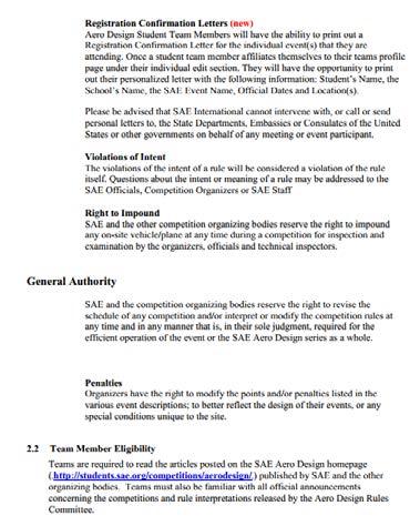
![Figure 2 Me 262, world first operational jet fighter [6] After the war was over, a great increase in commercial aviation was seen. Now days, the aviation industry has grown incredibly.](/docs-images/77/75547287/images/9-0.jpg "Technology and innovation has allowed for people to travel from continent to continent and even to outer space. 2. Project Formulation 2.1.")
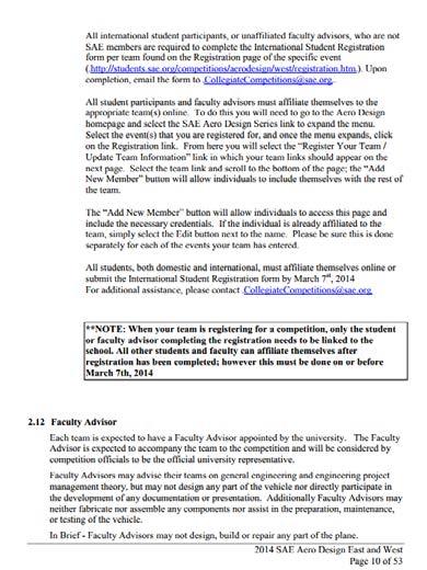
9 Figure 2 Me 262, world first operational jet fighter [6] After the war was over, a great increase in commercial aviation was seen. Now days, the aviation industry has grown incredibly. Technology and innovation has allowed for people to travel from continent to continent and even to outer space. 2. Project Formulation 2.1. Overview The SAE Aero Design competition is split up into 3 classes: Regular, Micro, and Open. It was decided to compete in the Regular class since it challenged us as engineers to test our knowledge. Each category sets parameters in regards to the size and dimensions of the aircraft, the weight, and power plant Project Objectives The team s objective is to work as a together to successfully design, test, and build a scale cargo-airplane within the competitions limits and technical requirements. This is all to improve our understanding and skills regarding engineering as a whole: we not only have to be concerned with the design of the plane but also with its economic and time counterparts Design Specifications, Constraints and Other Considerations To qualify to compete in the SAE Aero Design Series, your aircraft needs to comply with the requirements specified by the competition. Each class has their own requirements. The key requirements on which we will be designing our aircraft for the regular class are the following: The aircraft cannot exceed 65lbs (including cargo). Have a maximum combined length, width and height of 175 inches. Become airborne with a takeoff distance up to 61 meters 3
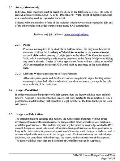
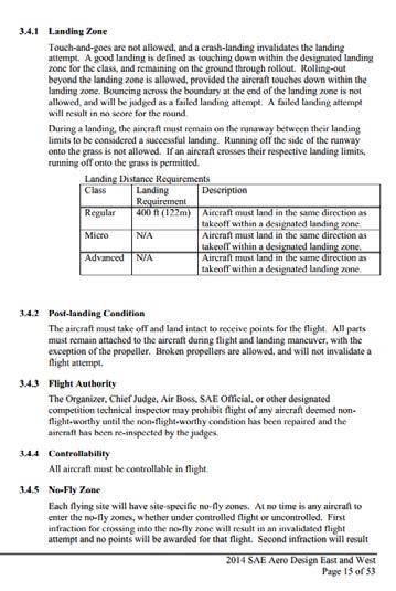
10 The aircraft must land within 122 meters of the landing zone. Aircrafts with fixed wings only. Fiber reinforced plastic is prohibited. No lead weights. No metal propellers or prop savers. No gyroscopic assist. Commercially engine mount and propeller are available. Aircraft must use a Single electric motor only. Lithium polymer batteries only. 4000mah, 25C. 4 cell 14.8 volt. Use a 1000 power limiter Payload and support, the weights must act as a homogeneous mass. Must use a spinner or a rounded safety nut. Analysis and testing of servo sizing is a must. Aircraft controls must not feature excessive slop. This leads to reduced controllability or control flutter in some cases. A complete description of the competition guidelines and requirements can be found on Appendix A. 3. Design Alternatives 3.1. Overview of Conceptual Designs Developed When designing an airplane, there are numerous alternatives relating to the design of the wings, empennage, and fuselage. The team will research the benefits and disadvantages of different airfoil shapes, tail designs, fuselage designs, and wing shape, size, and position. As well, ailerons and flaps are very important components of the wing that will be studied. Figure 3 illustrates the major components that make up an aircraft. 4
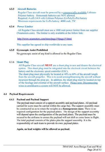
![Figure 3 Aircraft major components [7] 3.1.1. Wing Design Alternatives One of the biggest challenges of this competition is to create the most lift possible at the wings.](/docs-images/77/75547287/images/11-0.jpg "Since the set requirements restrict the aircraft s wingspan and motor power, the team needs carefully choose a wing design that will optimize the maximum load that the plane will carry.")
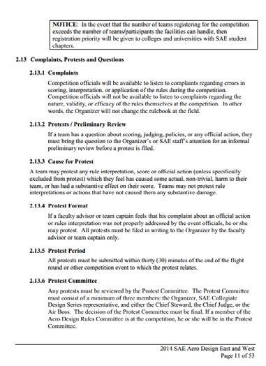
11 Figure 3 Aircraft major components [7] Wing Design Alternatives One of the biggest challenges of this competition is to create the most lift possible at the wings. Since the set requirements restrict the aircraft s wingspan and motor power, the team needs carefully choose a wing design that will optimize the maximum load that the plane will carry. The team s objective is to attain the maximum length of the airplane s wingspan possible without compromising the control and stability of the airplane. To achieve this, we need to take into consideration the fact that the fuselage and the height of the airplane will be affected by this criterion as well as the maneuverability of the airplane Wing Position As previously mentioned, there are numerous alternatives in the selection of the design of the airplane s wings. One of the factors to take into consideration while designing is the position of the wings. Figure 4 reflects the possibilities of wing position. 5
12 Figure 4 Wing Position Alternatives [8] The team will emphasize on three wing position alternatives which will function best based on our requirements; low wing, mid wing and high wing. Low Wing: Since the competition requires the airplane to have the payload inserted from the top and readily available to be inspected by judges, our first approach was to select the bottom wing in order to simplify the design. The main advantage for this wing position selection is the construction of the wing and the mounting of the landing gear. Since the structure of the wing could be manufactured as one piece, its strength would be perfect to withstand the weight of the fuselage and payload located above it. A disadvantage of this choice is the fact that the center of gravity of the plane would be above the wings making it the least stable design choice. Moreover, based on research of previous competitions, many airplanes undergo great wind gusts that shake the plane making it very hard to land and in many cases the low clearance between the wing and the floor were a decisive factor between a good landing and a crash. The low clearance wings have a greater risk of scraping the floor when landing. A solution to this problem would be to raise the airplane by making a landing gear higher, but this has an impact on the total height of the plane. Mid Wing: A mid wing design allows us to have the same loading capabilities as the bottom wing while giving us more clearance between the tip of the wings and the floor. When it comes to stability, the mid wing provides good stability and maneuverability in cargo planes. In this configuration, we can work with the position of the payload to find a center of gravity as close as possible between the wings. This 6
13 type of wing and center of gravity configuration is the most desired in the case of aerobatic airplanes which generally implement a symmetric type airfoil. For our purposes, we are not required to do any acrobatics while flying and even though it is a nice capability to have, we do not necessarily need it. The major disadvantage of this type of wing is the fact that it needs to be constructed in in two parts and attached to the side of the fuselage. In order to withstand the bending moment and shear stresses at the root of the wing associated with this design, we have to make the wing and fuselage stronger at these points and as a result we will be using more material and more weight would be added to the plane. High wing: The last wing position possibility is above the fuselage. We tried to avoid this particular configuration since at the time of loading and unloading the payload we need direct access to the cargo compartment straight from the top of the plane. The high wing position provides a number of advantages to the design that cannot be underestimated. This type of wing will offer the most stability during flight since the center of gravity will be directly underneath the wings. Even though this configuration does not provide as much maneuverability, we are not required a difficult course of flight. The competition rules require taking off and landing in the same direction and the same runway, making the course a simple circular path. The high wing will give us the most clearance with the floor reducing the risk of touching the ground with the wing when landing. As far as the fabrication of this wing, it would be ideal to make it in one piece. To make this option feasible, a quick way to load the payload will have to be deliberated Wing Shape: When it comes to wing shapes, there are numerous types of shapes and each one of them has its advantages and disadvantages. Figure 5 illustrates some wing shape possibilities. We will only concentrate in the shapes that are more suitable for our requirements while remaining simple at the time of construction. The tree types of shapes chosen are elliptical, tapered and rectangular wings. 7
14 Figure 5 Wing Shape Alternatives [9] Elliptical: This is the ideal subsonic departure point since it offers a minimum of induced drag for a given aspect ratio. An aspect ratio refers to the ratio of wing span to wing chord. The major disadvantage with this type of wing is the difficulty of its construction. Similarly, the stall characteristics of this wing are inferior to those of the tapered and rectangular wings. Tapered: Even though a tapered shape is not as aerodynamically efficient as the elliptical, it is one of the most desired shapes when it comes to weight and stiffness. In order to achieve the aerodynamic capabilities of an elliptical shape, tapered wings are customized through a variation of airfoils and wing twist until they produce a wing lift distribution as close as possible to the elliptical. Rectangular: This shape is the easiest to design and build, but also the least efficient of the three. A simple rectangular shape as it comes would create more drag than the two previous options. Even though in theory this is the easiest option to construct; for an optimum lift distribution adjustments to the airfoil profile and wing twist are required, making it a challenge design Ailerons and flaps Ailerons are located on the outer most part of the wing and they are used to roll the aircraft. Figure 6 illustrates the components in a wing. Flaps are mounted on the trailing edge of the wing; they are bigger than ailerons and are located closer to the fuselage. Flaps help on increasing the angle of curvature of the airfoil and as a 8


15 consequence increasing lift coefficient and drag, reducing the distance necessary to take off and land. This part of the design in directly related to the wing shape and needs to be determined once the selection is done. In the same manner as the wing construction, the ailerons and flaps are easier to design in the case of the rectangular and tapered wings than it is in the elliptical case. Figure 6 Wing Components [10] Airfoil The shape of the airfoil selected determines the drag and lift the aircraft will experience. It is crucial to select a shape that will optimize our design. Figure 7 illustrates common shapes of airfoils. Figure 7 Airfoil Shapes [11] 9

16 Flat bottom: After reviewing different sources, we realized that for our particular case this shape will be of poor performance since it does not provide as much lift as the other two candidates. After consulting with experienced pilots, the most common answer was that the behavior of the plane was erratic with this type of airfoil and it could lead to a crash if it was attempted to flight by a nonprofessional pilot. Symmetrical: This type of airfoil will provide lift and very good handling of the plane. This type of airfoil will generate lift based on the angle of attack of the wing. A symmetrical airfoil is the most desired case on aerobatic airplanes since it would behave in the same manner with the airplane ion the inverted position. Cambered: In contrast to a symmetrical airfoil, a cambered shape can produce lift at zero angle of attack. It provides the maximum lift coefficient and it reduces the stalling speed, meaning we can still flight at low speeds compared to symmetrical and flat bottom airfoils. This is the best choice for our purposes since we do not have a time limit to flight or perform aerobatics. Figure 8 Pressure Vectors and Flow Over a Camber Section illustrates the characteristics of the airfoil. Figure 8 Pressure Vectors and Flow Over a Camber Section [12] 10
17 Fuselage The fuselage is the main body of the aircraft, since it supports the empennage as well as the attachment of the power plant, landing gear and wings. There are three distinct parts of the fuselage nose, center, and rear. These will carry different loads depending on the purpose of the aircraft. However, the center section is generally always the largest and strongest of all three. This is due to the lift generated by the wings of the aircraft while in flight, which is transmitted using the center section to carry the complete airframe. The design of the aircraft is considered to be that of a cargo aircraft, with a truss fuselage and tapered nose and tail sections Battery (Payload bay)/compartment In normal aircrafts, the fuselage houses the passengers and the cargo. For this competition the fuselage will house only the payload area, this consists of the payload and payload support. A closed payload bay is required, with a volume dimension of 4x4x10 inches +1/8,-0. The payload bay has to have four sides, including bottom and top, and the aircraft must be able to take flight with or without the payload included. The payload support must also be made removable and the weights must remain fixed and as a homogeneous mass during and after flight Fuselage stresses Different stresses exist when the aircraft is on flight, and these stresses can act isolated or combined in a single part of the aircraft design. Figure 9 illustrates the forces acting on the fuselage that cause stresses. Tension and compression: These stresses are forces that push and pull the struts of the aircraft. Bending: are stresses that influence the interior structural members such as the wings spars while the aircraft is in flight; they apply tension in the lower side of the spar and compression in the top of it. Shear: stresses also exist in the aircraft; they are caused when forces push one another in a parallel displacement, and for instance when pieces of metal are being slide over the other. In aircrafts rivets and bolts carry shear. 11
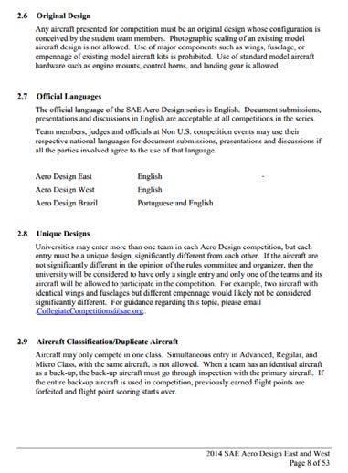
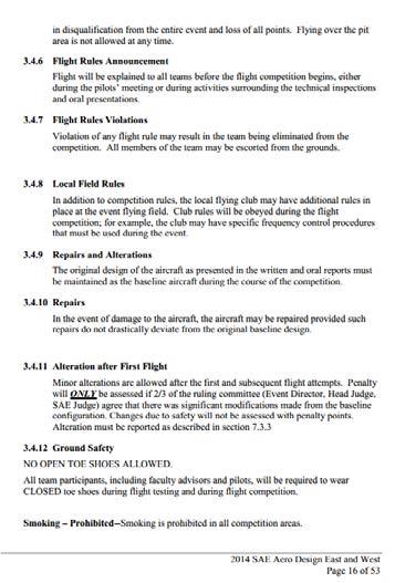
18 Torsion: stresses are also present in the aircraft, for instance when the engine exerts a force on the turbine axis or the crankshaft Figure 9 Forces Acting on Aircraft Empennage The empennage is the entire tail group which consisting of the vertical stabilizer, the horizontal stabilizer, rudder, and the elevator. Figure 10 illustrates the components mentioned. The tail of the airplane provides lift, stability and control. The tail is not design to create lift as the wing does; it is only intended to generate moment about the center of gravity of the plane in order to provide stability. The horizontal tail generates moment and the vertical tail yawing moment. The horizontal tail includes the elevators and the vertical tail the rudder. Just as wing shapes, there are several options available for the design. The shapes that we will take into consideration for our design are the conventional, T-tail, and H-tail configurations. Each one of them will offer advantages and disadvantages. 12
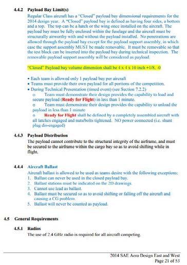
![Figure 10 Empennage Components [13] Conventional: Is the most widely used in commercial aircrafts and it provides sufficient lift and stability with the benefit of light weight.](/docs-images/77/75547287/images/19-0.jpg "Since the horizontal and vertical parts of the tail are attached to the fuselage it makes them structurally simple and light.")
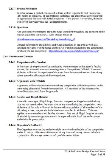
19 Figure 10 Empennage Components [13] Conventional: Is the most widely used in commercial aircrafts and it provides sufficient lift and stability with the benefit of light weight. Since the horizontal and vertical parts of the tail are attached to the fuselage it makes them structurally simple and light. Figure 11 Conventional Tail Design [14] T-tail: This tail is heavier than the conventional tail due to the stronger vertical tail necessary to support the horizontal tail weight and lifting forces. Since the horizontal tail is above the wing it is more aerodynamically efficient and a therefore its size can be reduced. 13
20 . Figure 12 T-Tail Design [14] H-tail: Is primary used to place the vertical tail in undisturbed air, allowing the rudders to be more effective and as a consequence they can be reduced in size. This type of tale is heavier than the conventional but it will allow a smaller vertical tail which could give us more room to expand our wingspan. This design is more effective than a same height conventional tail. Figure 13 H-Tail Design [14] 3.2. Design Alternatives Design Alternative A Table 1 Design Alternative A Specifications Wing Position Wing Shape Empennage Low Wing Elliptical Wing Conventional Tail 14
21 Figure 14 Design Alternative A The benefits to this design alternative are a low induced drag due to the elliptical shaped wing configuration, accessibility in the payload compartment due to the low wing configuration, and sufficient lift and stability due to the conventional tail design. Disadvantages to this alternative include difficulty in the construction of the elliptical wing design, less stable design due to low wing configuration, and low clearance between wing and floor Design Alternative B Table 2 Design Alternative B Specifications Wing Position Wing Shape Empennage High Wing Tapered Wing Conventional Tail Figure 15 Design Alternative B This design alternative will not be as efficient as the elliptical shaped wing but by customizing the airfoil we can achieve a distribution similar to the elliptical 15
22 configuration. The high wing design will give the aircraft the desired stability and clearance. A disadvantage to this alternative is the limited access to the payload compartment Design Alternative C Table 3 Design Alternative C Specifications Wing Position Wing Shape Empennage High Wing Tapered Wing H-Tail Figure 16 Design Alternative C As the previous alternative, this design will give the aircraft the desired stability and clearance. Additionally, the T-Tail will be more efficient than the conventional tail. Disadvantages to this alternative are the limited access to the payload compartment and added weight due to the T-tail configuration Feasibility Assessment In order to select an optimal design alternative for our airplane, the previous options where analyzed based on desired characteristics such as stability, construction, lift, and efficiency. 16

23 Stability and Control Construction Lift Capability Efficiency 1 0 Alternative A Alternative B Alternative C Figure 17 Feasibility Assessment Based on the results alternative B and C will have similar desired characteristics. Further selection will be decided based on material cost Proposed Design One challenging part of our design is the stress analysis in the structure. Since most of the lift force is applied at the wings, considering the tail also provides lift, it makes them a very crucial part of the structure. For the construction of the wing we are considering a mixture of wood, metal and plastic. Based on the weight and cost of these materials we have to make the best selection possible for our airplane. For the construction of the wing ribs we are considering balsa wood since it is light, cheap and easy to work on. Likewise, in order to add more strength and rigidity to the structure we are planning to add an internal transversal support made out of metal. The selection of this transversal support will be made between aluminum, steel and titanium rods or I beam shapes depending on the availability, dimensions and cost of the material. Moreover, the final layer of the wing will be covered with a plastic film that would perfectly shape the airfoil perimeter providing a smooth finish. Based on the research and description of the different combinations described above we have a basic idea of how the wings should look like. As a first approach, a cambered airfoil with high lift coefficient will be considered. The wing position proposed is the high wing since it will provide us with the most stability and safe landing as a 17
24 consequence of lower center of gravity and wing clearance with the floor respectively. For the top loading constrain we are considering making the wing as a one piece structure that could be tilt with a hinge and latch mechanism in order to provide access to the cargo bay. As far as wing shape the most appealing design is the tapered. It will offer a good wing lift distribution while maintaining the construction of the wing, flaps and ailerons simple. As previously mentioned, the structure would be a one piece wing over the top of the fuselage and it would be made out of balsa wood, internal metal supports and a plastic film cover. Once the wings and fuselage design have been decided we will concentrate in the tail section of the plane, for which we propose either a conventional or H-tail. As mentioned, the conventional tail serves its purpose and it is light weight, while the H-type tail is heavier but its shorter vertical stabilizer will allow us to expand even more our wingspan. 4. Project Management 4.1. Overview Behind a successful project is good project management. In order for the team to achieve a successful design, the team will be challenged to comply with the competition requirements, time, quality and budget. Through project management we will be able to organize tasks to the team efficiently to meet project deadlines, maintain a desired budget, and monitor and control the development of the aircraft Breakdown of Work into Specific Tasks This development of the aircraft will consist of three phases; design, manufacture, and validation & testing. For the design phase, the design of the airplane will broke down into three main components; structure, propulsion, and electrical. The design of the airplane will be distributed between the members based on the components required. Some components such as wing selection require more than one team member to assist in the design process. Once the design phase is completed we will begin the construction of the airplane. This will be distributed between the team members based on the skill they feel more comfortable with. 18

25 Throughout the development of the aircraft, testing will be performed to the parts designed to evaluate whether their characteristics meet the desired results. For this we will use finite element analysis, computational fluid dynamic analysis, wind tunnel testing, and bench testing Breakdown of Responsibilities among Team Members The responsibilities on each member where distributed taking into consideration their expertise in the area. Table 4 represents the division of responsibilities among the team members. The task assigned to each member will make that student the leader in the specified task. Nevertheless, team members will assist each other in all aspects of the project. Table 4 Division on Workload Task Research Fuselage Design Wing Selection Empennage Design Design Analysis Bench Testing Wind Tunnel Test Construction Designated Member All members Fred Al-Abdala Luis Vallejos Claudia Eyzaguirre Claudia Eyzaguirre Fred Al-Abdala Luis Vallejos All members 4.4. Organization of Work and Timeline Figure 18 Project Timeline 19
26 5. Analytical Analysis Kinematics Analysis Using the laws of kinematics we will guarantee the performance of our aircraft. Our main concern is having enough lift to be able to induce flight. Knowing the take-off distance limit for our competition and the kinematic equations for linear motion all we need is the information of the coefficients of the wings aerodynamics. These properties will be obtained using wind tunnel testing once the construction of the plane begins. To induce flight the aircraft needs to be able to produce enough thrust force to achieve the necessary lift. From kinematics: Where: F = sum of forces a = acceleration m = mass of the aircraft F = m a a = F m F = F motor(thrust) F friction F drag Knowing acceleration, we can use kinematics to find velocity as follows: Where: V 2 = V O a x V 2 = Take off velocity V O = initial velocity, starts from rest = 0 x = takeoff distance Solving for the acceleration: V2 a = 2 x Substituting back into the acceleration equation: 2 x = F m This means that the minimum truss force needed for lift is equal to: V 2 V 2 2 x m + F friction + F drag = F motor(thrust) 20

27 All of these unknowns need to be specified in order to solve for the minimum motor thrust. We know that the force of friction is produced between the tires of the aircraft and the takeoff pavement. This means that we approximate the friction coefficient; we also know that the drag force can be calculated from wind tunnel testing and it is dependent on the takeoff velocity and the aircraft configuration. After the building phase and wind tunnel testing, we will know the mass of the wings, payload, and aircraft s fuselage (including components). Wind tunnel testing will yield the data of lift force produced vs. wind speed, as well as the drag force produced at that wind speed for the specified wing configuration. 5.2 Wings The wings of the aircraft are an essential component to the performance of the plane. Hence, an analysis of the forces that exists along the wing and in the body of the aircraft is of great relevance. In order to determine the forces that exist on the wings when attached to the fuselage, we threat this case as a simple cantilever beam that experiences a distributed load along its length. This load is the lifting force. Figure 19 Loading on beam From the diagram above, we can calculate the shear and bending moment diagrams that the wings experience along its entire length. To obtain the necessary forces at any point in the beam, we pick a section and cut the beam at an arbitrary point we will call C. this point C must be between point A and B. we must then replace the distributed load and include the resultant force. This resultant force is equal to the load times half of the beam s length. In this new section, the beam will experience a moment and a shear force, which are represented in the free body diagram. 21

28 The new free body diagram is as follows: Figure 20 Moment calculation To calculate the free body diagram, both the shear force and moment must be defined. Using the laws of Kinematics: F Y = 0; ω x V = 0 V = ω x Where: V = Shear force ω = Lift force x = Distance from the beam starting edge. M = Moment Known for the Moment at arbitrary point C: M c = 0; ω x x 2 M = 0 M = 0.5 ω X 2 As expected, maximum shear and moment values occur at the point where the wing is attached to the fuselage and at the center point of both wings. This is due to the payload weight adding to the lift force of the aircraft. We took this condition in 22
29 consideration when designing our fuselage; this is why the fuselage we design has additional truss supports in the payload cargo to sustain these peak forces in the aircraft. The main goal is to avoid breaking the wings attachment to the fuselage during flight or take off. One of the options we have, is to reduce the wing s length (Span). Thus, reducing the total lift force, and stress on the wing saddle. Figure 21 Tapered wing ratio For the design of the wing we will use a tapered design to obtain higher stability as well as lift. Figure 21 shows the calculations needed to find the tapered wing ration. We will use 45% for the ratio since it will be as efficient as using an elliptical shape wing. The airfoil selected for the design will be the FX 74-Cl5-140 MOD based on research made on airfoils for heavy lift cargo planes [15]. 5.2 Fuselage It is important to try to make the surface of the airplane as rounded as possible or on the contrary it will experience separation drag. Aircraft structural members are designed to carry loads, and every square inch of every component must be considered in relation to the physical properties of the material of which it s made. Five mayor stresses contribute to the aircraft analysis; these are tension, compression, torsion, 23

30 shear and bending. For our design we are placing the heaviest structural members at intervals were concentrated loads exists, and at points where other elements such as stabilizers and the wings attach. For our design we are building a warren truss fuselage. They are the second best fuselages possible when flying scale aircrafts. Truss fuselages can manage tension and compression loads, they are light and are usually riveted or bolted into one piece. Usually trusses are made of balsa wood or aluminum. Another reason of why we chose truss fuselage is due to their high strength to weight ratio and extreme rigidity. In this design, compound trusses are used. Compound trusses are constructed by connecting two or more simple trusses to form a single rigid body. A simple truss is composed of three members that form a triangle. When analyzing trusses, it is assumed that the centroid axis of each member coincides with the line that connects the center of the adjacent members. It is also assumed that members carry only axial force and that they are connected by frictionless hinges. In the same manner, all loads and support reactions are applied at joints only. Figure 22 Warren Truss For our design deviations occur, since not only axial forces exist, but also shear and bending forces. And thus the truss is analyzed as a frame. When dealing with truss, zero force members need to be defined in order to cut down the number of unknowns when solving the equations. A zero force member is found when two members that are 24
31 connected to a joint have no external loads or reactions applied to it. Or when three members are connected to a joint, from which two are collinear, and the joint has no support or external loads. To test for failure in each member in the fuselage, two methods can be used to determine the forces of the members. These methods are the method of joints, and the method of sections which will be used to determine the tension and compression loads at each element in the truss frame. Trusses can also fail by buckling, which is given by the formula: Where P cr Buckling force. P cr = π2 EI (k L) 2 K=effective length factor (it is equal to one for ideal truss). E = Young modulus I = moment of inertia 6. Major Components Figure 23 Product Hierarchy 25

32 The airplane is broken down into two main systems, mechanical and electrical. Figure 23 illustrates the major component of each system. Components that will be designed and optimized include the fuselage, wings, and empennage. The electrical components along with the propulsion system for the aircraft will be purchased from available suppliers. The team will place emphasis on the design and optimization of the wings, fuselage, and empennage to attain high lift capacity. 7. Structural Design 7.1 Wings The structure on the wing will be constructed using Balsa wood to make the structure light allowing for more payload to be lifted. The team will analyze through simulations whether to keep the wing as one piece or divide it into two components. Leaving the wing as one piece will give more support and less reinforcement will be needed to support the structure. A drawback to this option will be limited access to the payload area. Since the competition requirements specify that the payload needs to be loaded through the top of the aircraft, having a one piece wing might become inconvenient. Figure 24 Structure of Wings and Fuselage 26


33 Figure 25 Wing Structure The structure of the wing will be optimized using SolidWorks s finite element analysis to decrease the number of ribs needed in the structure and so reducing weight and material costs. Figure 27 illustrates the mid-section of the wing and the selected airfoil. Figure 26 Top view of wing Figure 27 Section cut of wing 27


34 7.2 Fuselage Similar to the wings, the fuselage structure will be analyzed using SolidWorks to determine reliability in the structure, as well as, optimizing the fuselage to reduce cost. Figure 28 Fuselage Structure Figure 29 Front view of fuselage Figure 30 Fuselage top view 28

35 7.3 Empennage For the empennage the team selected an H-tail design. This shape will give the aircraft the stability it requires and at the same time it will help to obtain a higher wing span since the vertical stabilizer does not need to be as tall to be efficient. A NACA 009 airfoil was selected at the tail to provide stability. 8. Cost Analysis Figure 31 Empennage design An important aspect of every project is to maintain low costs. This can be accomplished by optimizing a design, researching suppliers for competitive prices and being efficient as an engineer by using time accordingly. Table 5 represent the estimated total cost for this project. The team will apply with FIU to obtain funding for trip expenses, as well as, contacting airlines to obtain better fares. Human hours are calculated with an average engineer salary of $25/hour. This total reflects the hours spent on the project as of November 24 th, 2013, this amount will increase as the project progresses. 29

36 Table 5 Cost Analysis Cost Competition Registration $700 Prototype $ Human hours 104 hours $2600 Plane tickets & lodging $ Prototype System Description There are two design options the team is considering. One of them includes the use of a ducted fan propeller. This design is to be analyzed using CFD to obtain aerodynamic properties. The following figures illustrate the design the team is considering. Figure 32 Design alternative 1 30

37 Figure 33 Design alternative Prototype Cost Analysis A main factor in our design is to keep the prototype cost low. This is accomplished by reducing the material needed in the design. The prototype cost analysis estimated in this section is for the current design which does not include optimization. The team s goal is to reduce costs through design and structural optimization. Table 6 Prototype Cost Analysis Component Cost Radio Control $ Electric Motor $ Batteries $ Servo Motors $ Landing Gear $ Raw Materials $ Total: $ Tests on Prototype To optimize the prototype design, computational fluid dynamic (CFD) analysis will be performed on the entire aircraft with the purpose of reducing drag and increasing lift capacity. Once a desired design has been obtained, the result will be tested trough wind tunnel testing to obtain experimental data to compare to the CFD analysis results. Following the prototype design, the team will perform structural optimization using 31
38 SolidWorks and ANSYS to analyze options to strengthen the aircrafts structure while reducing cost. 12. Conclusion Conclusion and Discussion The team continues to gather information necessary to achieve a successful design. It is understood the importance to meet deadlines, therefore the team is dedicated to comply with the timeline proposed. The research done has contributed to the selection on a preliminary design. Further understanding of the airplane s components along with the benefits and disadvantages of available wing, fuselage, and empennage configurations was achieved through research. The design of the aircraft will be done taking into consideration the competition requirement while designing with the purpose to lift as much load as possible Future Work The team will work on optimizing the lift and stability of the aircraft through CFD analysis. Testing and analysis of the design will be performed during the design process to make any necessary changes to the design prior to the construction phase. Research will be performed to analyze the use of retractable flaps, micro vortex generators, and a ducted fan propeller. 32
39 13. References [1] O. Alvarado, "2014 SAE Aero Design East and West," [Online]. Available: [2] T. D. Crouch, Wings: A History of Aviation from Kites to the Space Age, New York: W. W. Norton & Company, [3] S. Institution, "The Wright Brothers- The Invention of the Aerial Age," National Air and Space Museum, Smithsonian Institution., [Online]. Available: [4] J. T. Daniels, Artist, First successful flight of the Wright Flyer. [Art]. Library of Congress, [5] R. J. Overy, The Air War, , Potomac Books, [6] U. A. Force, Artist, Messerschmitt Me 262. [Art]. nationalmuseum.af.mil, [7] Airplane components. [Art]. U.S. Department of Transportation, [8] G. Inchbald, Artist, Wing configuration. [Art] [9] Wing Planform. [Art]. FAATest.com - Aviation Library. [10] Wing Components. [Art]. U.S. Department of Transportation, [11] P. Carpenter, Artist, [Art]. R/C Airplane World. [12] P. Carpenter, Artist, Pressure vectors. [Art] [13] Empennage components.. [Art]. U.S. Department of Transportation, [14] J. F. M. III, Artist, [Art]. Virginia Polytechnic Institute and State University, [15] M. S. Selig, "Summary of Low-Speed Airfoil Data," Department of Aeronautical and Astronautical Engineering, [16] "Aircraft Structure - An introduction to major airplane components," [Online]. Available: 33

40 Appendices Appendix A: Competition Rules 34
41 35
42 36
43 37
44 38
45 39
46 40
47 41
48 42

49 43
50 44
51 45
52 46
53 47
54 48
55 49
56 50
57 51
58 52
Team Introduction Competition Background Current Situation Project Goals Stakeholders Use Scenario Customer Needs Engineering Requirements
 Team Introduction Competition Background Current Situation Project Goals Stakeholders Use Scenario Customer Needs Engineering Requirements Constraints Project Plan Risk Analysis Questions Christopher Jones
SAE Aero Design. Apr 29, 2016
 SAE Aero Design Ali Alqalaf, Jasem Alshammari, Dong Yang Cao, Darren Frankenberger, Steven Goettl, and John Santoro Department of Mechanical Engineering Apr 29, 2016 Overview Introduction Need Statement
Design Considerations for Stability: Civil Aircraft
 Design Considerations for Stability: Civil Aircraft From the discussion on aircraft behavior in a small disturbance, it is clear that both aircraft geometry and mass distribution are important in the design
SAE Aero Design. Mid point Review. Ali Alqalaf, Jasem Alshammari, Dong Yang Cao, Darren Frankenberger, Steven Goettl, and John Santoro Team 16
 SAE Aero Design Mid point Review Ali Alqalaf, Jasem Alshammari, Dong Yang Cao, Darren Frankenberger, Steven Goettl, and John Santoro Team 16 Submitted towards partial fulfillment of the requirements for
SAE Mini BAJA: Suspension and Steering
 SAE Mini BAJA: Suspension and Steering By Zane Cross, Kyle Egan, Nick Garry, Trevor Hochhaus Team 11 Progress Report Submitted towards partial fulfillment of the requirements for Mechanical Engineering
1.1 REMOTELY PILOTED AIRCRAFTS
 CHAPTER 1 1.1 REMOTELY PILOTED AIRCRAFTS Remotely Piloted aircrafts or RC Aircrafts are small model radiocontrolled airplanes that fly using electric motor, gas powered IC engines or small model jet engines.
SAE BRAZIL AERODESIGN COMPETITION Final Report
 EML 4905 Senior Design Project A B.S. THESIS PREPARED IN PARTIAL FULFILLMENT OF THE REQUIREMENT FOR THE DEGREE OF BACHELOR OF SCIENCE IN MECHANICAL ENGINEERING SAE BRAZIL AERODESIGN COMPETITION Final Report
7. PRELIMINARY DESIGN OF A SINGLE AISLE MEDIUM RANGE AIRCRAFT
 7. PRELIMINARY DESIGN OF A SINGLE AISLE MEDIUM RANGE AIRCRAFT Students: R.M. Bosma, T. Desmet, I.D. Dountchev, S. Halim, M. Janssen, A.G. Nammensma, M.F.A.L.M. Rommens, P.J.W. Saat, G. van der Wolf Project
AIRCRAFT DESIGN SUBSONIC JET TRANSPORT
 AIRCRAFT DESIGN SUBSONIC JET TRANSPORT Analyzed by: Jin Mok Professor: Dr. R.H. Liebeck Date: June 6, 2014 1 Abstract The purpose of this report is to design the results of a given specification and to
Lockheed Martin. Team IDK Seung Soo Lee Ray Hernandez Chunyu PengHarshal Agarkar
 Lockheed Martin Team IDK Seung Soo Lee Ray Hernandez Chunyu PengHarshal Agarkar Abstract Lockheed Martin has developed several different kinds of unmanned aerial vehicles that undergo harsh forces when
SAE AERO DESIGN EAST COMPETITION Final Report
 EML 4905 Senior Design Project A SENIOR DESIGN PROJECT PREPARED IN PARTIAL FULFILLMENT OF THE REQUIREMENT FOR THE DEGREE OF BACHELOR OF SCIENCE IN MECHANICAL ENGINEERING SAE AERO DESIGN EAST COMPETITION
A SOLAR POWERED UAV. 1 Introduction. 2 Requirements specification
 A SOLAR POWERED UAV Students: R. al Amrani, R.T.J.P.A. Cloosen, R.A.J.M. van den Eijnde, D. Jong, A.W.S. Kaas, B.T.A. Klaver, M. Klein Heerenbrink, L. van Midden, P.P. Vet, C.J. Voesenek Project tutor:
Powertrain Design for Hand- Launchable Long Endurance Unmanned Aerial Vehicles
 Powertrain Design for Hand- Launchable Long Endurance Unmanned Aerial Vehicles Stuart Boland Derek Keen 1 Justin Nelson Brian Taylor Nick Wagner Dr. Thomas Bradley 47 th AIAA/ASME/SAE/ASEE JPC Outline
monthly NEWSLETTER OCTOBER 2015 Copyright 2015 M-Fly
 monthly NEWSLETTER OCTOBER 2015 Copyright 2015 M-Fly mfly@umich.edu IN THIS ISSUE M-Fly spent the summer prototyping advanced class systems and becoming experienced with composite manufacturing. As members
Design, Fabrication and Testing of an Unmanned Aerial Vehicle Catapult Launcher
 ISBN 978-93-84422-40-0 Proceedings of 2015 International Conference on Computing Techniques and Mechanical Engineering (ICCTME 2015) Phuket, October 1-3, 2015, pp. 47-53 Design, Fabrication and Testing
Revisiting the Calculations of the Aerodynamic Lift Generated over the Fuselage of the Lockheed Constellation
 Eleventh LACCEI Latin American and Caribbean Conference for Engineering and Technology (LACCEI 2013) International Competition of Student Posters and Paper, August 14-16, 2013 Cancun, Mexico. Revisiting
SAE BRAZIL AERODESIGN COMPETITION 25% Report
 EML 4905 Senior Design Project A B.S. THESIS PREPARED IN PARTIAL FULFILLMENT OF THE REQUIREMENT FOR THE DEGREE OF BACHELOR OF SCIENCE IN MECHANICAL ENGINEERING SAE BRAZIL AERODESIGN COMPETITION 25% Report
ECO-CARGO AIRCRAFT. ISSN: International Journal of Science, Engineering and Technology Research (IJSETR) Volume 1, Issue 2, August 2012
 Volume 1, Issue 2, August 2012") ECO-CARGO AIRCRAFT Vikrant Goyal, Pankhuri Arora Abstract- The evolution in aircraft industry has brought to us many new aircraft designs. Each and every new design is a step towards a greener tomorrow.
ECO-CARGO AIRCRAFT Vikrant Goyal, Pankhuri Arora Abstract- The evolution in aircraft industry has brought to us many new aircraft designs. Each and every new design is a step towards a greener tomorrow.
SAE Aero Design. Mid-point Review 3/10/2016. By Ali Alqalaf, Jasem Alshammari, Dong Yang Cao, Darren Frankenberger, Steven Goettl, and John Santoro
 SAE Aero Design Mid-point Review By Ali Alqalaf, Jasem Alshammari, Dong Yang Cao, Darren Frankenberger, Steven Goettl, and John Santoro 3/10/2016 Overview Introduction Problem Definition Need Statement
The Effects of Damage and Uncertainty on the Aeroelastic / Aeroservoelastic Behavior and Safety of Composite Aircraft
 The Effects of Damage and Uncertainty on the Aeroelastic / Aeroservoelastic Behavior and Safety of Composite Aircraft Presented by Professor Eli Livne Department of Aeronautics and Astronautics University
Load Analysis and Multi Body Dynamics Analysis of Connecting Rod in Single Cylinder 4 Stroke Engine
 IJSRD - International Journal for Scientific Research & Development Vol. 3, Issue 08, 2015 ISSN (online): 2321-0613 Load Analysis and Multi Body Dynamics Analysis of Connecting Rod in Single Cylinder 4
New Frontier in Energy, Engineering, Environment & Science (NFEEES-2018 ) Feb
 Feb") RESEARCH ARTICLE OPEN ACCESS DESIGN AND IMPACT ANALYSIS OF A ROLLCAGE FOR FORMULA HYBRID VEHICLE Aayush Bohra 1, Ajay Sharma 2 1(Mechanical department, Arya College of Engineering & I.T.,kukas, Jaipur)
RESEARCH ARTICLE OPEN ACCESS DESIGN AND IMPACT ANALYSIS OF A ROLLCAGE FOR FORMULA HYBRID VEHICLE Aayush Bohra 1, Ajay Sharma 2 1(Mechanical department, Arya College of Engineering & I.T.,kukas, Jaipur)
XIV.C. Flight Principles Engine Inoperative
 XIV.C. Flight Principles Engine Inoperative References: FAA-H-8083-3; POH/AFM Objectives The student should develop knowledge of the elements related to single engine operation. Key Elements Elements Schedule
ASME Human Powered Vehicle
 ASME Human Powered Vehicle By Yousef Alanzi, Evan Bunce, Cody Chenoweth, Haley Flenner, Brent Ives, and Connor Newcomer Team 14 Mid-Point Review Document Submitted towards partial fulfillment of the requirements
The Effects of Damage and Uncertainty on the Aeroelastic / Aeroservoelastic Behavior and Safety of Composite Aircraft. JAMS Meeting, May
 The Effects of Damage and Uncertainty on the Aeroelastic / Aeroservoelastic Behavior and Safety of Composite Aircraft JAMS Meeting, May 2010 1 JAMS Meeting, May 2010 2 Contributors Department of Aeronautics
2012 Baja SAE Drivetrain
 2012 Baja SAE Drivetrain A thesis submitted to the Faculty of the Mechanical Engineering Technology Program of the University of Cincinnati in partial fulfillment of the requirements for the degree of
The Airplane That Could!
 The Airplane That Could! Critical Design Review December 6 th, 2008 Haoyun Fu Suzanne Lessack Andrew McArthur Nicholas Rooney Jin Yan Yang Yang Agenda Criteria Preliminary Designs Down Selection Features
ME 455 Lecture Ideas, Fall 2010
 ME 455 Lecture Ideas, Fall 2010 COURSE INTRODUCTION Course goal, design a vehicle (SAE Baja and Formula) Half lecture half project work Group and individual work, integrated Design - optimal solution subject
Preliminary Detailed Design Review
 Preliminary Detailed Design Review Project Review Project Status Timekeeping and Setback Management Manufacturing techniques Drawing formats Design Features Phase Objectives Task Assignment Justification
Chapter 10 Parametric Studies
 Chapter 10 Parametric Studies 10.1. Introduction The emergence of the next-generation high-capacity commercial transports [51 and 52] provides an excellent opportunity to demonstrate the capability of
SAE Baja - Drivetrain
 SAE Baja - Drivetrain By Ricardo Inzunza, Brandon Janca, Ryan Worden Team 11A Concept Generation and Selection Document Submitted towards partial fulfillment of the requirements for Mechanical Engineering
Theory of Flight. Main Teaching Points. Definition Parts of an Airplane Aircraft Construction Landing Gear Standard Terminology
 Theory of Flight 6.01 Aircraft Design and Construction References: FTGU pages 9-14, 27 Main Teaching Points Parts of an Airplane Aircraft Construction Standard Terminology Definition The airplane is defined
Introduction: Problem statement
 Introduction: Problem statement The goal of this project is to develop a catapult system that can be used to throw a squash ball the farthest distance and to be able to have some degree of accuracy with
a Challenge for Lift-Based, Rigid Wing AWE Systems
 Eric Nguyen Van, Lorenzo Fagiano, Stephan Schnez ABB Corporate Research December 8 th, 2015 Take-Off and Landing a Challenge for Lift-Based, Rigid Wing AWE Systems Outline ABB s Interest in AWE assessment
CONCEPTUAL DESIGN OF ECOLOGICAL AIRCRAFT FOR COMMUTER AIR TRANSPORTATION
 26 TH INTERNATIONAL CONGRESS OF THE AERONAUTICAL SCIENCES CONCEPTUAL DESIGN OF ECOLOGICAL AIRCRAFT FOR COMMUTER AIR TRANSPORTATION Yasuhiro TANI, Tomoe YAYAMA, Jun-Ichiro HASHIMOTO and Shigeru ASO Department
Reducing Landing Distance
 Reducing Landing Distance I've been wondering about thrust reversers, how many kinds are there and which are the most effective? I am having a debate as to whether airplane engines reverse, or does something
Appenidix E: Freewing MAE UAV analysis
 Appenidix E: Freewing MAE UAV analysis The vehicle summary is presented in the form of plots and descriptive text. Two alternative mission altitudes were analyzed and both meet the desired mission duration.
Remote Control Helicopter. Engineering Analysis Document
 Remote Control Helicopter By Abdul Aldulaimi, Travis Cole, David Cosio, Matt Finch, Jacob Ruechel, Randy Van Dusen Team 04 Engineering Analysis Document Submitted towards partial fulfillment of the requirements
10th Australian International Aerospace Congress
 AUSTRALIAN INTERNATIONAL AEROSPACE CONGRESS Paper presented at the 10th Australian International Aerospace Congress incorporating the 14th National Space Engineering Symposium 2003 29 July 1 August 2003
Design, analysis and mounting implementation of lateral leaf spring in double wishbone suspension system
 Design, analysis and mounting implementation of lateral leaf spring in double wishbone suspension system Rahul D. Sawant 1, Gaurav S. Jape 2, Pratap D. Jambhulkar 3 ABSTRACT Suspension system of an All-TerrainVehicle
International Journal of Scientific & Engineering Research, Volume 4, Issue 7, July ISSN BY B.MADHAN KUMAR
 International Journal of Scientific & Engineering Research, Volume 4, Issue 7, July-2013 485 FLYING HOVER BIKE, A SMALL AERIAL VEHICLE FOR COMMERCIAL OR. SURVEYING PURPOSES BY B.MADHAN KUMAR Department
Uncontrolled copy not subject to amendment. Airframes. Revision 1.00
 Uncontrolled copy not subject to amendment Airframes Revision 1.00 Chapter 4: Fuselage Learning Objectives The purpose of this chapter is to discuss in more detail the first of the 4 major components
Chapter 3: Aircraft Construction
 Chapter 3: Aircraft Construction p. 1-3 1. Aircraft Design, Certification, and Airworthiness 1.1. Replace the letters A, B, C, and D by the appropriate name of aircraft component A: B: C: D: E: 1.2. What
AERONAUTICAL ENGINEERING
 AERONAUTICAL ENGINEERING SHIBIN MOHAMED Asst. Professor Dept. of Mechanical Engineering Al Ameen Engineering College Al- Ameen Engg. College 1 Aerodynamics-Basics These fundamental basics first must be
SAE Aero Design. Problem Definition and Project Plan
 SAE Aero Design Problem Definition and Project Plan By Ali Alqalaf, Jasem Alshammari, Dong Yang Cao, Darren Frankenberger, Steven Goettl, and John Santoro 10/23/2015 Overview Introduction Need Statement
Clean Sky 2. LifeCraft Demonstrationt (IADP RC 2 & ITDs) Consultation meetings Brussels th December 2012 OUTLINE
 Consultation meetings Brussels th December 2012 OUTLINE") Clean Sky 2 LifeCraft Demonstrationt (IADP RC 2 & ITDs) Consultation meetings Brussels 10-14 th December 2012 1 1 LifeCraft - The Compound Demo OUTLINE Presentation of the Compound R/C Concept Impact &
Clean Sky 2 LifeCraft Demonstrationt (IADP RC 2 & ITDs) Consultation meetings Brussels 10-14 th December 2012 1 1 LifeCraft - The Compound Demo OUTLINE Presentation of the Compound R/C Concept Impact &
Propeller Blade Bearings for Aircraft Open Rotor Engine
 NTN TECHNICAL REVIEW No.84(2016) [ New Product ] Guillaume LEFORT* The Propeller Blade Bearings for Open Rotor Engine SAGE2 were developed by NTN-SNR in the frame of the Clean Sky aerospace programme.
STRUCTURAL DESIGN AND ANALYSIS OF ELLIPTIC CYCLOCOPTER ROTOR BLADES
 16 TH INTERNATIONAL CONFERENCE ON COMPOSITE MATERIALS STRUCTURAL DESIGN AND ANALYSIS OF ELLIPTIC CYCLOCOPTER ROTOR BLADES In Seong Hwang 1, Seung Yong Min 1, Choong Hee Lee 1, Yun Han Lee 1 and Seung Jo
Simulating Rotary Draw Bending and Tube Hydroforming
 Abstract: Simulating Rotary Draw Bending and Tube Hydroforming Dilip K Mahanty, Narendran M. Balan Engineering Services Group, Tata Consultancy Services Tube hydroforming is currently an active area of
The following slideshow and talk were presented at the Uber Elevate Summit on April 25 th, The text included here is an approximate transcript
 The following slideshow and talk were presented at the Uber Elevate Summit on April 25 th, 2017. The text included here is an approximate transcript of the speech given by Jay Carter, founder and CEO of
SAE Baja - Drivetrain
 SAE Baja - Drivetrain By Ricardo Inzunza, Brandon Janca, Ryan Worden Team 11 Engineering Analysis Document Submitted towards partial fulfillment of the requirements for Mechanical Engineering Design I
Part II. HISTORICAL AND ENGINEERING ANALYSIS OF AIRSHIP PLAN-AND- DESIGN AND SERVICE DECISIONS
 CONTENTS MONOGRAPHER S FOREWORD DEFENITIONS, SYMBOLS, ABBREVIATIONS, AND INDICES Part I. LAWS AND RULES OF AEROSTATIC FLIGHT PRINCIPLE Chapter 1. AIRCRAFT FLIGHT PRINCIPLE 1.1 Flight Principle Classification
FSAE SUSPENSION SYSTEM
 EML 4905 Senior Design Project A B.S. THESIS PREPARED IN PARTIAL FULFILLMENT OF THE REQUIREMENT FOR THE DEGREE OF BACHELOR OF SCIENCE IN MECHANICAL ENGINEERING FSAE SUSPENSION SYSTEM Michael Benitez Yussimil
NEW DESIGN AND DEVELELOPMENT OF ESKIG MOTORCYCLE
 NEW DESIGN AND DEVELELOPMENT OF ESKIG MOTORCYCLE Eskinder Girma PG Student Department of Automobile Engineering, M.I.T Campus, Anna University, Chennai-44, India. Email: eskindergrm@gmail.com Mobile no:7299391869
A STUDY OF STRUCTURE WEIGHT ESTIMATING FOR HIGH ALTITUDE LONG ENDURENCE (HALE) UNMANNED AERIAL VEHICLE (UAV)
 UNMANNED AERIAL VEHICLE (UAV)") 5 TH INTERNATIONAL CONGRESS OF THE AERONAUTICAL SCIENCES A STUDY OF STRUCTURE WEIGHT ESTIMATING FOR HIGH ALTITUDE LONG ENDURENCE (HALE UNMANNED AERIAL VEHICLE (UAV Zhang Yi, Wang Heping School of Aeronautics,
5 TH INTERNATIONAL CONGRESS OF THE AERONAUTICAL SCIENCES A STUDY OF STRUCTURE WEIGHT ESTIMATING FOR HIGH ALTITUDE LONG ENDURENCE (HALE UNMANNED AERIAL VEHICLE (UAV Zhang Yi, Wang Heping School of Aeronautics,
Flugzeugentwurf / Aircraft Design SS Part 35 points, 70 minutes, closed books. Prof. Dr.-Ing. Dieter Scholz, MSME. Date:
 DEPARTMENT FAHRZEUGTECHNIK UND FLUGZEUGBAU Flugzeugentwurf / Aircraft Design SS 2015 Duration of examination: 180 minutes Last Name: Matrikelnummer: First Name: Prof. Dr.-Ing. Dieter Scholz, MSME Date:
STATIC AND FATIGUE ANALYSIS OF LEAF SPRING-AS A REVIEW
 STATIC AND FATIGUE ANALYSIS OF LEAF SPRING-AS A REVIEW Vishal Gavali 1, Mahesh Jadhav 2, Digambar Zoman 3 1,2, 3 Mechanical Engineering Department, LGNSCOE Anjaneri Nashik,(India) ABSTRACT In engineering
Prop effects (Why we need right thrust) Torque reaction Spiraling Slipstream Asymmetric Loading of the Propeller (P-Factor) Gyroscopic Precession
 Torque reaction Spiraling Slipstream Asymmetric Loading of the Propeller (P-Factor) Gyroscopic Precession") Prop effects (Why we need right thrust) Torque reaction Spiraling Slipstream Asymmetric Loading of the Propeller (P-Factor) Gyroscopic Precession Propeller torque effect Influence of engine torque on aircraft
Prop effects (Why we need right thrust) Torque reaction Spiraling Slipstream Asymmetric Loading of the Propeller (P-Factor) Gyroscopic Precession Propeller torque effect Influence of engine torque on aircraft
LEAD SCREWS 101 A BASIC GUIDE TO IMPLEMENTING A LEAD SCREW ASSEMBLY FOR ANY DESIGN
 LEAD SCREWS 101 A BASIC GUIDE TO IMPLEMENTING A LEAD SCREW ASSEMBLY FOR ANY DESIGN Released by: Keith Knight Kerk Products Division Haydon Kerk Motion Solutions Lead Screws 101: A Basic Guide to Implementing
2.2 Schedule
 Table of Contents 1.0 Executive Summary------------------------------------------------------------3 2.0 Management Summary--------------------------------------------------------4 2.1 Team Organization-----------------------------------------------------4
Jay Gundlach AIAA EDUCATION SERIES. Manassas, Virginia. Joseph A. Schetz, Editor-in-Chief. Blacksburg, Virginia. Aurora Flight Sciences
 Jay Gundlach Aurora Flight Sciences Manassas, Virginia AIAA EDUCATION SERIES Joseph A. Schetz, Editor-in-Chief Virginia Polytechnic Institute and State University Blacksburg, Virginia Published by the
Rotary Wing Micro Air Vehicle Endurance
 Rotary Wing Micro Air Vehicle Endurance Klaus-Peter Neitzke University of Applied Science Nordhausen, Nordhausen, Germany neitzke@fh-nordhausen.de Abstract One of the first questions to pilots of rotor
MASSACHUSETTS INSTITUTE OF TECHNOLOGY Department of Aeronautics and Astronautics
 MASSACHUSETTS INSTITUTE OF TECHNOLOGY Department of Aeronautics and Astronautics 16.00 Introduction to Aerospace and Design Problem Set #4 Issued: February 28, 2002 Due: March 19, 2002 ROCKET PERFORMANCE
SAE Mini BAJA: Suspension and Steering
 SAE Mini BAJA: Suspension and Steering By Zane Cross, Kyle Egan, Nick Garry, Trevor Hochhaus Team 11 Project Progress Submitted towards partial fulfillment of the requirements for Mechanical Engineering
DEVELOPMENT OF A CARGO AIRCRAFT, AN OVERVIEW OF THE PRELIMINARY AERODYNAMIC DESIGN PHASE
 ICAS 2000 CONGRESS DEVELOPMENT OF A CARGO AIRCRAFT, AN OVERVIEW OF THE PRELIMINARY AERODYNAMIC DESIGN PHASE S. Tsach, S. Bauminger, M. Levin, D. Penn and T. Rubin Engineering center Israel Aircraft Industries
Environmentally Focused Aircraft: Regional Aircraft Study
 Environmentally Focused Aircraft: Regional Aircraft Study Sid Banerjee Advanced Design Product Development Engineering, Aerospace Bombardier International Workshop on Aviation and Climate Change May 18-20,
Section 2: Basic Aerobatics
 Section 2: Basic Aerobatics Airplane Considerations and Control Setup Primary to Aerobatic Airplane Transition Parallel Positioning B-34 Basic Aerobatics Introduction Aerobatics is unarguably the most
Stationary Bike Generator System
 Central Washington University ScholarWorks@CWU All Undergraduate Projects Undergraduate Student Projects Spring 2017 Stationary Bike Generator System Rakan Alghamdi Central Washington University, rk_rk11@hotmail.com
Semi-Active Suspension for an Automobile
 Semi-Active Suspension for an Automobile Pavan Kumar.G 1 Mechanical Engineering PESIT Bangalore, India M. Sambasiva Rao 2 Mechanical Engineering PESIT Bangalore, India Abstract Handling characteristics
Connor Needham Roger Williams University Bristol, RI, United States. Jeremy Kacher Roger Williams University Bristol, RI, United States
 ASEE 2014 Zone I Conference, April 3-5, 2014, University of Bridgeport, Bridgpeort, CT, USA. Design of a Vertical Axis Wind Turbine for Urban Areas Hidden In Plain Sight Wind Energy Conservation System
Development of a Subscale Flight Testing Platform for a Generic Future Fighter
 Development of a Subscale Flight Testing Platform for a Generic Future Fighter Christopher Jouannet Linköping University - Sweden Subscale Demonstrators at Linköping University RAVEN Rafale Flight Test
F.I.R.S.T. Robotic Drive Base
 F.I.R.S.T. Robotic Drive Base Design Team Shane Lentini, Jose Orozco, Henry Sick, Rich Phelan Design Advisor Prof. Sinan Muftu Abstract F.I.R.S.T. is an organization dedicated to inspiring and teaching
Y. Lemmens, T. Benoit, J. de Boer, T. Olbrechts LMS, A Siemens Business. Real-time Mechanism and System Simulation To Support Flight Simulators
 Y. Lemmens, T. Benoit, J. de Boer, T. Olbrechts LMS, A Siemens Business Real-time Mechanism and System Simulation To Support Flight Simulators Smarter decisions, better products. Contents Introduction
IPRO 317-VTOL Aircraft for the Masses
 IPRO 317-VTOL Aircraft for the Masses Jesse Collins Brandon Honore Julia Northrop Neal Patel Kabir Metha Douglas Elkins Sean McCann Benjamin Smith Akash Garg Vikram Kumar Allow Us To Introduce VTOL Vertical
Design And Development Of Roll Cage For An All-Terrain Vehicle
 Design And Development Of Roll Cage For An All-Terrain Vehicle Khelan Chaudhari, Amogh Joshi, Ranjit Kunte, Kushal Nair E-mail : khelanchoudhary@gmail.com, amogh_4291@yahoo.co.in,ranjitkunte@gmail.com,krockon007@gmail.com
TAKEOFF PERFORMANCE ground roll
 TAKEOFF PERFORMANCE An airplane is motionless at the end of a runway. This is denoted by location O. The pilot releases the brakes and pushes the throttle to maximum takeoff power, and the airplane accelerates
MOONBUGGY REPORT. Submitted by Galgotias College of Engineering and Technology Team 1 1, Knowledge Park-2 Greater Noida, Uttar Pradesh INDIA
 MOONBUGGY REPORT Submitted by Galgotias College of Engineering and Technology Team 1 1, Knowledge Park-2 Greater Noida, Uttar Pradesh INDIA TEAM DETAILS Our Moonbuggy design consists of its suspension
Structural Analysis of Student Formula Race Car Chassis
 Structural Analysis of Student Formula Race Car Chassis Arindam Ghosh 1, Rishika Saha 2, Sourav Dhali 3, Adrija Das 4, Prasid Biswas 5, Alok Kumar Dubey 6 1Assistant Professor, Dept. of Mechanical Engineering,
Wing Cuff Design for Cessna CJ1
 Wing Cuff Design for Cessna CJ1 AAE 415 Project Purdue University Saturday, December 10th, 2004 Brian Adams Kevin Clark Greg Davidson Phil Spindler Contents Background of Problem Literature Review Design
Design and Vibrational Analysis of Flexible Coupling (Pin-type)
") Design and Vibrational Analysis of Flexible Coupling (Pin-type) 1 S.BASKARAN, ARUN.S 1 Assistant professor Department of Mechanical Engineering, KSR Institute for Engineering and Technology, Tiruchengode,
Design and Vibrational Analysis of Flexible Coupling (Pin-type) 1 S.BASKARAN, ARUN.S 1 Assistant professor Department of Mechanical Engineering, KSR Institute for Engineering and Technology, Tiruchengode,
FE151 Aluminum Association Inc. Impact of Vehicle Weight Reduction on a Class 8 Truck for Fuel Economy Benefits
 FE151 Aluminum Association Inc. Impact of Vehicle Weight Reduction on a Class 8 Truck for Fuel Economy Benefits 08 February, 2010 www.ricardo.com Agenda Scope and Approach Vehicle Modeling in MSC.EASY5
INVESTIGATION OF ICING EFFECTS ON AERODYNAMIC CHARACTERISTICS OF AIRCRAFT AT TSAGI
 INVESTIGATION OF ICING EFFECTS ON AERODYNAMIC CHARACTERISTICS OF AIRCRAFT AT TSAGI Andreev G.T., Bogatyrev V.V. Central AeroHydrodynamic Institute (TsAGI) Abstract Investigation of icing effects on aerodynamic
Experimental Validation of a Scalable Mobile Robot for Traversing Ferrous Pipelines
 Project Number: MQP TP1- IPG1 Experimental Validation of a Scalable Mobile Robot for Traversing Ferrous Pipelines A Major Qualifying Project (MQP) Submitted to the Faculty of WORCESTER POYTECHNIC INSTITUTE
Preface. Acknowledgments. List of Tables. Nomenclature: organizations. Nomenclature: acronyms. Nomenclature: main symbols. Nomenclature: Greek symbols
 Contents Preface Acknowledgments List of Tables Nomenclature: organizations Nomenclature: acronyms Nomenclature: main symbols Nomenclature: Greek symbols Nomenclature: subscripts/superscripts Supplements
High aspect ratio for high endurance. Mechanical simplicity. Low empty weight. STOVL or STOL capability. And for the propulsion system:
 Idealized tilt-thrust (U) All of the UAV options that we've been able to analyze suffer from some deficiency. A diesel, fixed-wing UAV could possibly satisfy the range and endurance objectives, but integration
DESIGN AND ANALYSIS OF PRE- INSERTION RESISTOR MECHANISM
 DESIGN AND ANALYSIS OF PRE- INSERTION RESISTOR MECHANISM Bhavik Bhesaniya 1, Nilesh J Parekh 2, Sanket Khatri 3 1 Student, Mechanical Engineering, Nirma University, Ahmedabad 2 Assistant Professor, Mechanical
Systems Group (Summer 2012) 4 th Year (B.Eng) Aerospace Engineering Candidate Carleton University, Ottawa,Canada Mail:
 4 th Year (B.Eng) Aerospace Engineering Candidate Carleton University, Ottawa,Canada Mail:") Memo Airport2030_M_Family_Concepts_of_Box_Wing_12-08-10.pdf Date: 12-08-10 From: Sameer Ahmed Intern at Aero Aircraft Design and Systems Group (Summer 2012) 4 th Year (B.Eng) Aerospace Engineering Candidate
Memo Airport2030_M_Family_Concepts_of_Box_Wing_12-08-10.pdf Date: 12-08-10 From: Sameer Ahmed Intern at Aero Aircraft Design and Systems Group (Summer 2012) 4 th Year (B.Eng) Aerospace Engineering Candidate
TITLE: EVALUATING SHEAR FORCES ALONG HIGHWAY BRIDGES DUE TO TRUCKS, USING INFLUENCE LINES
 EGS 2310 Engineering Analysis Statics Mock Term Project Report TITLE: EVALUATING SHEAR FORCES ALONG HIGHWAY RIDGES DUE TO TRUCKS, USING INFLUENCE LINES y Kwabena Ofosu Introduction The impact of trucks
AE 451 Aeronautical Engineering Design Final Examination. Instructor: Prof. Dr. Serkan ÖZGEN Date:
 Instructor: Prof. Dr. Serkan ÖZGEN Date: 11.01.2012 1. a) (8 pts) In what aspects an instantaneous turn performance is different from sustained turn? b) (8 pts) A low wing loading will always increase
Methodology for Distributed Electric Propulsion Aircraft Control Development with Simulation and Flight Demonstration
 1 Methodology for Distributed Electric Propulsion Aircraft Control Development with Simulation and Flight Demonstration Presented by: Jeff Freeman Empirical Systems Aerospace, Inc. jeff.freeman@esaero.com,
External Hard Drive: A DFMA Redesign
 University of New Mexico External Hard Drive: A DFMA Redesign ME586: Design for Manufacturability Solomon Ezeiruaku 4-23-2013 1 EXECUTIVE SUMMARY The following document serves to illustrate the effects
Rotorcraft Gearbox Foundation Design by a Network of Optimizations
 13th AIAA/ISSMO Multidisciplinary Analysis Optimization Conference 13-15 September 2010, Fort Worth, Texas AIAA 2010-9310 Rotorcraft Gearbox Foundation Design by a Network of Optimizations Geng Zhang 1
Linear Induction Motor (LIMO) Modular Test Bed for Various Applications
 Modular Test Bed for Various Applications") Linear Induction Motor (LIMO) Modular Test Bed for Various Applications ECE 4901 Senior Design I Fall 2013 Fall Project Report Team 190 Members: David Hackney Jonathan Rarey Julio Yela Faculty Advisor
Linear Induction Motor (LIMO) Modular Test Bed for Various Applications ECE 4901 Senior Design I Fall 2013 Fall Project Report Team 190 Members: David Hackney Jonathan Rarey Julio Yela Faculty Advisor
SAE Aero Design Flagstaff, AZ May 2, 2009
 SAE Aero Design Flagstaff, AZ 86001 May 2, 2009 Dr. John Tester Dept. of Mechanical Engineering Northern Arizona University Building # 69 Flagstaff, AZ 86001 Dr. John Tester: This cover letter serves as
ECSE-2100 Fields and Waves I Spring Project 1 Beakman s Motor
 Names _ and _ Project 1 Beakman s Motor For this project, students should work in groups of two. It is permitted for groups to collaborate, but each group of two must submit a report and build the motor
DESIGN OF AUTOMOBILE S BODY SHAPE AND STUDY ON EFFECT OF AERODYNAMIC AIDS USING CFD ANALYSIS
 DESIGN OF AUTOMOBILE S BODY SHAPE AND STUDY ON EFFECT OF AERODYNAMIC AIDS USING CFD ANALYSIS Akshay S 1, Ashik Vincent 2, Athul Anand R 3, George Kurian 4, Dr. Shajan Kuriakose 5 1,2,3,4 B-Tech Degree
PREDICTION OF PISTON SLAP OF IC ENGINE USING FEA BY VARYING GAS PRESSURE
 PREDICTION OF PISTON SLAP OF IC ENGINE USING FEA BY VARYING GAS PRESSURE V. S. Konnur Department of Mechanical Engineering, BLDEA s Engineering College, Bijapur, Karnataka, (India) ABSTRACT The automotive
Air Buzz. 32nd Annual AHS International Student Design Competition
 Air Buzz 32nd Annual AHS International Student Design Competition Faculty Advisor: Dr. Daniel Schrage, Daniel.Schrage@aerospace.gatech.edu Ezgi Selin Akdemir esakdemir@gmail.com Undergraduate Middle East
KEYWORDS: ANSYS, Clamping effects, Leaf spring, Pro-E. International Journal of Computational Engineering Research Vol, 03 Issue, 10
 International Journal of Computational Engineering Research Vol, 03 Issue, 10 Leaf Spring Analysis with Eyes Using FEA B.Mahesh Babu 1, D.Muralidhar Yadav 2, N.Ramanaiah 3 1 Assistant Professor, Dr.Samuel
A practical investigation of the factors affecting lift produced by multi-rotor aircraft. Aaron Bonnell-Kangas
 A practical investigation of the factors affecting lift produced by multi-rotor aircraft Aaron Bonnell-Kangas Bonnell-Kangas i Table of Contents Introduction! 1 Research question! 1 Background! 1 Definitions!