TECHNOLOGICAL ADVANCEMENT. SUSTAINABLE DEVELOPMENT
|
|
|
- Daisy Chapman
- 6 years ago
- Views:
Transcription
1 TECHNOLOGICAL ADVANCEMENT. SUSTAINABLE DEVELOPMENT

2 Table of contents 1. Filters 11 Sea water filters Flanged in-line sea-water filters 12 Flanged salt-water filters, one cartridge type 13 Screen nipple filters, one cartridge type 14 Screen in-line sea-water, oil and fuel filters with the hose coupling 15 Oil and fuel filters Flanged in-line oil and fuel filters 16 Flanged aperture oil and fuel filters 17 Portable oil and fuel filters 18 Slotted nipple oil and fuel filters 19 Flanged duplex filters with the switching unit of cork type 20 Duplex slotted nipple filters with the switching unit of cork type 21 Oil and fuel filters with polymeric filter cartridges 22 Final fuel filter-separators 23 Diesel fuel filters Flanged angular filters with nonwoven filter element 24 Automatic fuel filter 25 Other filters Flanged in-line fresh-water filters 26 Screen nipple one-fold filters 27 Duplex slotted-disk filters 28 Ion-exchange filters 29 2


3 2. Fuel-preparation equipment 30 Separation unit BS 1,0/1, Separation unit BS 1,5/2, Separation unit BS 3,0/2, Separation unit BS 10/6, Separation unit BS 25/7, Separation unit SSAF-5, SSAF Oil separation unit with the heating BSP Oil separation unit BSP-02 to separate B-3V oil 39 Diesel fuel preparation unit, UTDT 41 Integrated heavy oil fuel preparation unit, KUPT-3 42 Unit to purify aviation fuel, UAT type Water treatment equipment 44 Ballast water treatment system SOOB Oily water treatment unit UONSV 48 Wastewater treatment unit UOSV AIR AND GAS PURIFICATION EQUIPMENT 51 System for the purification and cooling of exhaust gas of heat engines 52 Air separators 53 Inertial separator 54 3

4 5. Heat-exchange equipment 55 Coolers Oil cooler OKP OKN OKN ND 58 OKP OKP OKP OKP OKP MkHD 64 МО-25V 65 МО-63-1-М 66 Water coolers OKN OKN OKN OKP OPV 71 VkHD 72 Oil and water coolers OKN OKN OKN OKN OKN OKN Condensate cooler KhV Cooler PGV Water, oil and fuel heaters High-speed hot-water heaters, PS type 81 Capacitive water heaters, PE type 82 Steam sanitary water marine heaters, PV type 83 Marine steam oil heaters, PM type 84 4


5 High-speed hot-water heaters, PJe, PPJe type 85 Exhausted steam condensers, KhV 86 Exhausted steam condenser KhV Drier of air and steam mixture Water-supply equipment 91 Hydrofors 92 Hydrofors of the fire-extinguishing system Other equipment 95 Gate valves (on order) Sea inlet (on order) Valve (on order) Deck plates 96 Run-down boxes 97 Automatic closing of air pipes 98 Solution storage tanks 99 Solution preparation station 100 Feeder 101 Roll-type drives to control armature 102 Vertical; horizontal; single- and two-row radiators 103 Starting valve II-15R 104 Siren I Blast signal 106 Pumping station 107 Anchor windlasses B1-B5 108 Fire-extinguishing units Fixed foam apparatus, medium expansion factor СО-I Ст 109 Fixed foam apparatus, medium expansion factor СО-II Ст 110 Fixed foam apparatus, medium expansion factor СО-IV Ст Licenses and certificates 112 5

6 VINETA LTD., ENGINEERING PLANT 6

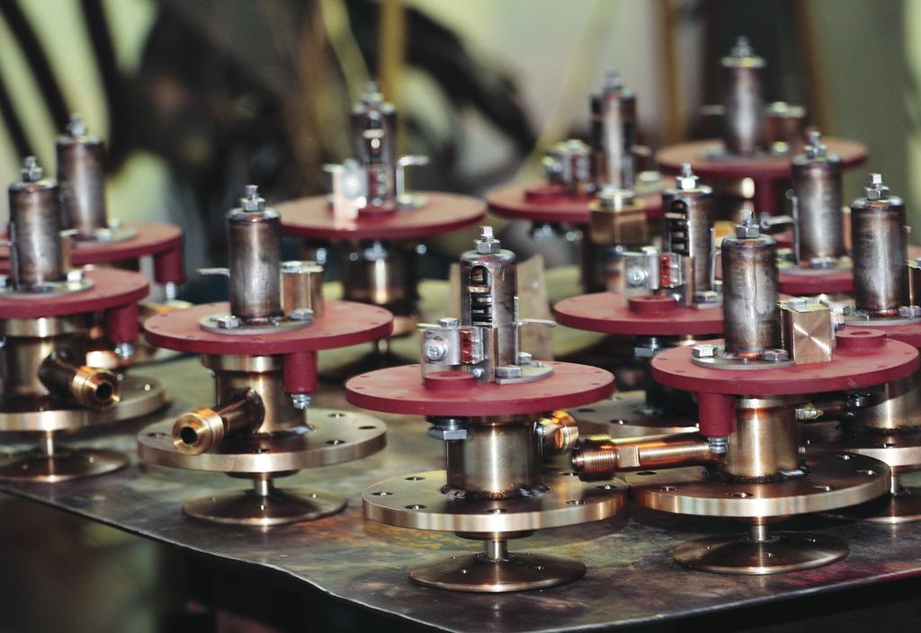
7 Vineta Ltd. was founded in The dynamically developing enterprise is occupied with the design and manufacturing of the produce for the navy and civil fleet, atomic industry, transport, fuel and energy sector as well as agriculture. The operating area of Vineta Ltd. is situated in Nikolskoe, Tosno district, Leningrad region. Trying to tie-up the highly-qualified personnel, we do our utmost to provide our staff with the most comfortable work environment: performance reward system; interning of young specialists who continue to work at our enterprise on a permanent basis; training, courses and seminars. Due to the growing volumes of the construction of ships and other vessels, the demand on our products is steadily growing. That is why we are extending our staff of designer and manufacturing engineers. For those needs we have purchased and equipped a new office building. Within the program to expand the manufacturing capacity, at the time being we are repairing and equipping a new workshop with the up-to-date equipment. It helps to significantly reduce order schedules and cover the growing demand on the produce of our enterprise. 7


8 The enterprise has all the necessary licenses and certificates. The quality management system of Vineta Ltd. is certified in accordance with international standard ISO 9001:2008 and 8 GOST R Russian state standard ISO 9001:2008. The detailed information on licenses and certificates can be found on page 113 LICENSES AND CERTIFICATES.


9 AT THE TIME BEING THE ENTERPRISE PRODUCES THE FOLLOWING GOODS IN LOTS: FILTERS FUEL-PREPARATION EQUIPMENT WATER TREATMENT EQUIPMENT AIR AND GAS PURIFICATION EQUIPMENT HEAT EXCHANGE EQUIPMENT WATER-SUPPLY EQUIPMENT OTHER EQUIPMENT 9
10 Identification codes and abbreviations Conducting media: A SW FW BW DO O air sea water fresh water bilge water diesel oil oil TO turbine oil 46 S 28%CaC12 LO F BP OP stream 28% calcium chloride brine light oil fuel black product oil product Application: Ltb CO products, allowed to be used on low-tonnage boats and ships of national purpose products, allowed to be used on Customer s objects

11 FILTERS 1 FILTERS Sea water filters FUNCTION AND TECHNICAL DATA Flanged in-line sea-water filters Flanged salt-water filters, one cartridge type Screen nipple filters, one cartridge type Screen in-line sea-water, oil and fuel filters with the hose coupling Oil and fuel filters Flanged in-line oil and fuel filters Flanged aperture oil and fuel filters Portable oil and fuel filters Slotted nipple oil and fuel filters Flanged duplex filters with the switching unit of cork type Duplex slotted nipple filters with the switching unit of cork type Oil and fuel filters with polymeric filter cartridges Final fuel filter-separators Diesel fuel filters Flanged angular filters with nonwoven filter element Automatic fuel filter Other filters Flanged in-line fresh-water filters Screen nipple one-fold filters Duplex slotted-disk filters Ion-exchange filters 1
 ИУШД.061144.008 (427-03.")
12 FILTERS SEA WATER FILTERS Flanged in-line sea-water filters 1 FUNCTION AND TECHNICAL DATA Nominal pressure: 2, 4, 6, 40 kg-f/cm 2 Conducting medium: sea water Filtration capacity: 0, 3; 2, 5; 4, 5 mm Material: Cu-Ni alloy, bronze Flanges: under GOST DN, mm PN, kg-f/cm 2 Denomination Index Material H, mm L, mm Mass, kg ИУШД ( ) ИУШД ( ) ИУШД ( ) ИУШД ( ) ФЗВ 40/ Bronze ,0 ФЗВ 40/ М Cu-Ni alloy ,0 ФЗВ 50/4-2. 5М Cu-Ni alloy ,0 ФЗВ 80/4-2. 5М Cu-Ni alloy ,0 ФЗВ 100/2-2,5 Cu-Ni alloy , ИУШД ( ) ИУШД ( ) ИУШД ( ) ФЗВ 100/4-2. 5М Cu-Ni alloy ,0 ФЗВ 125/4-2. 5М Cu-Ni alloy ,0 ФЗВ 150/4-2. 5М Cu-Ni alloy ,0 ФВ 150/6-4,5 Bronze , ИУШД ( ) ИУШД ( ) ИУШД ( ) ИУШД ( ) ФЗВ 200/4-2. 5М Cu-Ni alloy ,0 ФЗВ 250/4-2. 5М Cu-Ni alloy ,0 ФЗВ 300/4-2. 5М Cu-Ni alloy ,0 ФЗВ 350/4-2. 5М Cu-Ni alloy ,0 12
13 SEA WATER FILTERS Flanged salt-water filters, one cartridge type FILTERS FUNCTION AND TECHNICAL DATA 1 Working pressure: 40, 100 kg-f/cm 2 Conducting medium: sea water Filtration capacity: 2,5 mm Material: titanium, bronze Flanges: under GOST Setting position: vertical with the cover being in the top position Permissible pressure drop: max 0,8 kg-f/cm 2 DN, mm PN, kg-f/cm 2 Denomination Index Medium Material H, mm L, mm Mass, kg ФЗВ 40/ SW Bronze , ИУШД ФЗВ 50/40-2,5 SW Bronze , ФЗВ 80/40-2,5 SW Bronze , ФЗВ 100/40-2,5 SW Bronze , ФЗВ 150/40-2,5 SW Bronze , ФЗВ 200/40-2,5 SW Bronze , ВНТА ФЗВ 250/40-2,5 SW Bronze , SW Titanium , SW Titanium , SW Titanium , ИУШД SW Titanium , SW Titanium , SW Titanium , ВНТА SW Titanium , ИУШД SW Titanium , SW Titanium SW Titanium
 4,0(40,0) 3 Conducting medium Salt water 4 Degree of filtration, mm")
14 FILTERS SEA WATER FILTERS Screen nipple filters, one cartridge type 1 FUNCTION AND TECHNICAL DATA Working pressure: 40 kg-f/cm 2 Conducting medium: salt water Filtration capacity: 2,5 mm Material: carbon steel Flanges: under GOST Name Nominal value 1 Internal diameter, mm 32,0 2 Working pressure, Pw, MPa (kg-f/cm 2 ) 4,0(40,0) 3 Conducting medium Salt water 4 Degree of filtration, mm 2,5 5 Mass, kg 13,0 6 Length, mm 210,0 7 Width, mm 154,0 8 Height, mm 270,0 9 Max permissible pressure drop, MPa (kg-f/cm 2 ) 0,05(0,5) 10 Continuous work period, h. 3000,0 14

15 SEA WATER FILTERS Screen in-line sea-water, oil and fuel filters with the hose coupling FILTERS FUNCTION AND TECHNICAL DATA Working pressure: 1, 3, 4 kg-f/cm 2 1 Conducting medium: oil, fuel, sea water Filtration capacity: 2,5 mm Material: light alloy, Cu-Ni alloy Flanges: under GOST Setting position: vertical, with the cover being in the top position DN, mm PN, kg-f/cm 2 Denomination Index Medium Material H, mm L, mm Mass, kg 20 3 ИУШД ФМТ 20/3-0,5 O, F Light alloy , ИУШД ФМТ 32/3-0,5 O, F Light alloy , ИУШД ФМТ 40/3-0,5 O, F Light alloy , SW Cu-Ni alloy , ВНТА ФЗВ 20/4-2,5 SW Cu-Ni alloy , ФЗВ 20/4-2,5 SW Cu-Ni alloy , SW Cu-Ni alloy , ФЗВ 32/4-2,5 SW Cu-Ni alloy , ФЗВ 32/4-2,5 SW Cu-Ni alloy , ФШ 50/4-2,5 SW Cu-Ni alloy , ВНТА ФЗВ 50/4-2,5 SW Cu-Ni alloy ВНТА ФЗВ 65/4-2,5 SW Cu-Ni alloy , ФЗВ 80/4-2,5 SW Cu-Ni alloy ,7 15

16 FILTERS OIL AND FUEL FILTERS Flanged in-line oil and fuel filters 1 FUNCTION AND TECHNICAL DATA Working pressure: 6 kg-f/cm 2 Conducting medium: oil and fuel, fresh water Filtration capacity: 1 mm for oil and fuel Material: stainless steel, carbon steel Flanges: under GOST DN, mm Denomination Index Medium Material H, mm L, mm Mass, kg 20 ИУЩД ( ) ФМТ 20/6-1 FW Carbon steel ,0 32 ИУЩД ( ) ФМТ 32/6-1 FW Carbon steel ,5 50 ИУЩД ( ) ФМТ 50/6-1-1 FW Stainless steel ,5 50 ИУЩД ( ) ФМТ 50/6-1 FW Carbon steel ,5 80 ИУЩД ( ) ФМТ 80/6-1-1 FW Stainless steel ,0 80 ИУЩД ( ) ФМТ 80/6-1 FW Carbon steel ,0 100 ИУЩД ( ) ФМТ 100/6-1-1 FW Stainless steel ,0 100 ИУЩД ( ) ФМТ 100/6-1 FW Carbon steel ,0 150 ИУЩД ( ) ФМТ 150/6-1 FW Carbon steel ,0 200 ИУЩД ( ) ФМТ 200/6-1 FW Carbon steel ,0 250 ИУЩД ( ) ФМТ 250/6-1 FW Carbon steel ,0 300 ИУЩД ( ) ФМТ 300/6-1 FW Carbon steel ,0 16


17 OIL AND FUEL FILTERS Flanged aperture oil and fuel filters FILTERS FUNCTION AND TECHNICAL DATA Working pressure: 6, 40 kg-f/cm 2 1 Conducting medium: oil and fuel Filtration capacity: 0,25; 0,4 mm Material: carbon steel Flanges: under GOST Possible to equip with the servodrive for the automatic cleaning, as well as with solenoid vent valve. Possible to equip with the steam heating for the high-viscosity liquid pumping. DN, mm PN, kg-f/cm 2 Denomination Index Medium Material H, mm L, mm Mass, kg ИУШД ФЩ 32/40-0,25 O,F Carbon steel , ИУШД ФЩ 32/40-0,4 O,F Carbon steel , ИУШД ФЩ 40/40-0,25 O,F Carbon steel , ИУШД ФЩ 40/40-0,4 O,F Carbon steel , ИУШД ФЩ 50/6-0,25 O,F Carbon steel , ИУШД ФЩ 50/6-0,4 O,F Carbon steel , ИУШД ФЩ 50/40-0,25 O,F Carbon steel , ИУШД ФЩ 50/40-0,4 O,F Carbon steel , ИУШД ФЩ 65/6-0,4 O,F Carbon steel , ИУШД ФЩ 65/40-0,25 O,F Carbon steel , ИУШД ФЩ 65/40-0,4 O,F Carbon steel , ИУШД ФЩ 65/6-0,25 O,F Carbon steel , ИУШД ФЩ 65/6-0,4 O,F Carbon steel ,4 17

18 FILTERS OIL AND FUEL FILTERS PORTABLE OIL AND FUEL FILTERS 1 FUNCTION AND TECHNICAL DATA Working pressure: 1 kg-f/cm 2 Conducting medium: oil, fuel Filtration capacity: 1,7 mm Material: carbon steel Flanges: under GOST Setting position: vertical with the air valve being in the top position DN, mm PN, kg-f/cm 2 Denomination Index Medium Material H, mm L, mm Mass, kg O, F Carbon steel , ФМТ 50/10-1,7 O, F Carbon steel , ФМТ 100/10-1,7 O, F Carbon steel , ФМТ 100/10-1,7К O, F Carbon steel , ФМТ 150/10-1,7 O, F Carbon steel , ИУШД СБ FMT150/10-1,7 O, F Carbon steel

19 OIL AND FUEL FILTERS Slotted nipple oil and fuel filters FILTERS FUNCTION AND TECHNICAL DATA Working pressure: 10, 25, 40 kg-f/cm 2 1 Conducting medium: oil, fuel Filtration capacity: 0,25 mm Material: carbon steel Flanges: under GOST DN, mm PN, kg-f/cm 2 Denomination Index Medium Material H, mm L, mm Mass, kg O, F Carbon steel , O, F Carbon steel , ФЩ 20/10-0,15 O, F Carbon steel , ИУШД ФЩ 20/40-0,25 O, F Carbon steel , ИУШД ФЩ 25/10-0,25 O, F Carbon steel , ИУШД ФЩ 32/10-0,25 O, F Carbon steel , ИУШД ФЩ 25/10-0,4 O, F Carbon steel ,0 19

20 FILTERS OIL AND FUEL FILTERS Flanged duplex filters with the switching unit of cork type 1 FUNCTION AND TECHNICAL DATA Working pressure: 6 kg-f/cm 2 Conducting medium: oil, fuel Filtration capacity: 0,5 mm Material: carbon steel Flanges: under GOST DN, mm PN, kg-f/cm 2 Denomination Medium Material H, mm L, mm Mass, kg O, F Carbon steel O, F Carbon steel ИУШД O, F Carbon steel

21 OIL AND FUEL FILTERS Duplex slotted nipple filters with the switching unit of cork type FILTERS FUNCTION AND TECHNICAL DATA Working pressure: 25 kg-f/cm 2 1 Conducting medium: oil, fuel Filtration capacity: 0,4 mm Material: carbon steel Flanges: under GOST DN, mm PN, kg-f/cm 2 Denomination Degree of filtration, mm Medium Material H, mm L, mm Mass, kg ,4 O, F Carbon steel ,3 21

22 FILTERS OIL AND FUEL FILTERS OIL AND FUEL FILTERS WITH POLYMERIC FILTER CARTRIDGES 1 FUNCTION AND TECHNICAL DATA Working pressure: 10 kg-f/cm 2 Conducting medium: oil, diesel fuel Filtration capacity: 15 micron Material: stainless steel Function: fine purification of oil and diesel fuel from free and part of water contaminant, mechanical impurities and biofouling. The filtering base consists of 21 polymeric renewable cartridge Index FM 50/15 FT 80/60 Medium to be cooled Oil Diesel fuel Temperature of the medium to be cooled, С from 0 С up to +50 from 0 С up to +50 Filtration capacity, micron Working pressure, kg-f/cm Max capacity, m 3 /h Overall dimensions, LxWxH, mm 700х725х х720х1260 Mass, kg


23 OIL AND FUEL FILTERS FINAL FUEL FILTER-SEPARATORS FILTERS FUNCTION AND TECHNICAL DATA 1 Filters FST 40/10, FST 50/10, FST 50/4 together with the set of filter elements are intended to be installed as a fine purification unit for the diesel fuel, turbine and motor oil from free and part of dissolved water, mechanical impurities and biofouling at the cw mode in marine systems. Parameter FST 40/10 FST 50/10 FST 50/4 DN, mm Working pressure, MPa (kg-f/cm 2 ), max 1,0 (10) 1,0 (10) 0,4 (4) Fuel rated capacity, m 3 /h, max 3,0 5,0 Oil rated capacity, m 3 /h, max 1,5 2,5 Medium Diesel fuel under GOST , Turbine oil ТП22, ТП46 under GOST , Motor oil for diesel engines under GOST , Oil for marine gas turbines under GOST Diesel fuel under GOST , Turbine oil ТП22, ТП46 under GOST Max temperature of the medium to be purified, С max 80 Max ambient temperature, С max 50 Dry mass, kg, max 72,0 172,0 123,1 Operational weight, kg, max 100,0 215,0 166,0 Max permissible pressure drop under the filter clogging at the rated capacity, MPa 0,1 Max permissible pressure drop under the clean filter at the rated capacity, MPa 0,01 Kinematic viscosity of the fuel to be purified, cst under 40 С, max 2 45 Kinematic viscosity of the motor oil to be purified, cst under 100 С, max 20,0 Kinematic viscosity of the turbine oil to be purified, cst under 50 С, max 60,0 60,0 Degree of filtration at the rated capacity, mcm, max 5,0 Degree of filtration from water at the rated capacity, % (at the initial water content in the fuel being up traces of water to 3%) Weight of the set of filter elements, kg, max 15,0 38,4 38,4 23


24 FILTERS DIESEL FUEL FILTERS Flanged angular filters with nonwoven filter element 1 FUNCTION AND TECHNICAL DATA Fuel filters ФНТ 40/10, ФНТ 80/10, ФНТ 125/10 are intended to be installed in ships and vessels for the fine filtration of diesel fuel GOST and from mechanical impurities. The filter guarantees continuous and safe performance in terms of rocking under lurch of 45, and continuous lurch of 15, trim difference of 5 and short-term trim difference up to 10. The filter and its fixation to the foundation are impact-resistant under current norms of ship equipment impact-resistance. The filter vibration-resistance corresponds to current norms of ship equipment vibrationresistance. Name Unit of measurement ФНТ 40/10 ИУШД Specification data ФНТ 80/10 ИУШД ФНТ 125/ Type One-cartridge with nonwoven filter element Capacity up to 30 up to 80 up to 120 Working pressure kg-f/cm Internal diameter mm Degree of filtration mc Temperature of the diesel fuel to be filtered C 5 35 Max. pressure drop under filter kg-f/cm 2 1,5 Hydraulic resistance of clean filter under the temperature of 20 C and capacity kg-f/cm 2 0,5 0,5 0,3 m 3 /h
. 1 There is a hot standby system.")
25 DIESEL FUEL FILTERS Automatic fuel filter FILTERS FUNCTION AND TECHNICAL DATA Two-phase cleaning: the medium enters the primary purification chamber (slotted filter). Then the medium is directed to the fine purification chamber (degree of filtration 25 micron). 1 There is a hot standby system. Shall the maximum pressure drop be achieved in any chamber, the dirty line is locked and the flow is directed to the filter standby line. Each chamber is equipped with the automatic cleaning system. The fine filtration chamber is equipped with the reverse flow cleaning system as well as with the steam blowing function. Parameter Value Medium to be filtered diesel fuel,heavy oil from 50 cst Working pressure, MPa 0,4-1,0 Purge steam pressure, MPa 0,5 Degree of filtration, abs., micron 25 Overall dimensions 945х560х910 LхWхH, mm 945х560х910 Inlet/outlet DN 32 Weight, kg

26 FILTERS OTHER FILTERS Flanged in-line fresh-water filters 1 FUNCTION AND TECHNICAL DATA Nominal pressure: 6 kg-f/cm 2 Conducting medium: oil and fuel, fresh water Filtration capacity: 2.5 mm for fresh water Material: stainless steel, carbon steel Flanges: under GOST DN, mm Denomination Index Medium Material H, mm L, mm Mass, kg 20 ИУШД ( ) ФПВ 20/6-2,5 FW Carbon steel ,2 32 ИУШД ( ) ФПВ 32/6-2,5-1 FW Stainless steel ,5 32 ИУШД ( ) ФПВ 32/6-2,5 FW Carbon steel ,5 50 ИУШД ( ) ФПВ 50/6-2,5-1 FW Stainless steel ,5 50 ИУШД ( ) ФПВ 50/6-2,5 FW Carbon steel ,5 80 ИУШД ( ) ФПВ 80/6-2,5 FW Carbon steel ,0 100 ИУШД ( ) ФПВ 100/6-2,5 FW Carbon steel ,0 150 ИУШД ( ) ФПВ 150/6-2,5 FW Carbon steel ,0 200 ИУШД ( ) ФПВ 200/6-2,5 FW Carbon steel ,0 250 ИУШД ( ) ФПВ 250/6-2,5 FW Carbon steel ,0 300 ИУШД ( ) ФПВ 300/6-2,5 FW Carbon steel ,0 26

27 OTHER FILTERS SCREEN NIPPLE ONE-FOLD FILTERS FILTERS FUNCTION AND TECHNICAL DATA Working pressure: 6, 25, 40 kg-f/cm 2 1 Conducting medium: oil, fuel, sea water, bilge water Filtration capacity: 0,25 mm Material: titanium, bronze, light alloy Flanges: under GOST DN, mm PN, kg-f/cm 2 Denomination Index Medium Material H, mm L, mm Mass, kg 20 6 ИУШД ФМТ 20/6-0,25 O, F Light alloy , ИУШД ФМТ 20/6-0,25-1 O, F Light alloy , ФМТ 25/6-0,25 O, F Light alloy , ФМТ 25/6-0,25-1 O, F Light alloy , ИУШД ФМТ 32/6-0,25 O, F Light alloy , ИУШД ФМТ 32/6-0,25-1 O, F Light alloy , ИУШД O, F Stainless steel , SW Titanium , SW Titanium , SW Titanium , SW Titanium , SW, bilge water SW, bilge water SW, bilge water Titanium ,2 Titanium ,2 Titanium , SW Titanium , ИУШД ФЗВ 50/40-2,5 SW Bronze , ФЗВ 80/40-2,5 SW Bronze ,0 27
 1,0 (10)")
28 FILTERS OTHER FILTERS DUPLEX SLOTTED-DISK FILTERS 1 FUNCTION AND TECHNICAL DATA Working pressure: 10 kg-f/cm 2 Conducting medium: feed water, distillate Filtration capacity: 0,15 mm Material: corrosion-resistant steel Flanges: under GOST Setting position of the cover: top, bottom and sideways Name Value Internal diameter, mm 50 Working pressure, Pw, MPa (kg-f/cm 2 ) 1,0 (10) Conducting medium Feed water, distillate Temperature of conducting medium, K ( C) from 273 up to 363 (from 0 up to 90) Degree of filtration, mm 0,15 Permissible pressure drop, MPa (kg-f/cm 2 ) 0,2 (2,0) Dry/active mass, kg 54/62 Capacity, m 3 /h 15 28

29 OTHER FILTERS ION-EXCHANGE FILTERS FILTERS FUNCTION AND TECHNICAL DATA 1 Working pressure: 10 kg-f/cm 2 Conducting medium: feed water, distillate Filtration capacity: 0,15 mm Material: corrosion-resistant steel Flanges: under GOST Index Water pressure before the filter, MPa Max permissible productivity, m 3 /h under deionization and deoxygenation Cavity volume, m 3 Steel weight for cavity, kg Drainage sublayer BT 1-00c alloy weight for cavity, kg softening low top low top low top Single-cavity ФИ ФИ ФИ ,6 ФИ ,0 20,0 0, ФИ ФИ ФИ ФИ ФИ ФИ ФИ ФИ ФИ ФИ ФИ ФИ ФИ ФИ Two-cavity ФИД ФИД ФИД
30 FILTERS 1 FUNCTION AND TECHNICAL DATA 30

31 2 FUEL-PREPARATION EQUIPMENT Separation unit BS 1,0/1,1-5 Separation unit BS 1,5/2,2-5 FUNCTION AND TECHNICAL DATA FUEL-PREPARATION EQUIPMENT Separation unit BS 3.0/2,2-5 Separation unit BS 10/6,1-5 2 Separation unit BS 25/7,5-5 Separation unit SSAF-5, SSAF-10 Oil separation unit with the heating BSP-01 Oil separation unit BSP-02 to separate B-3V oil Diesel fuel preparation unit, UTDT Integrated heavy oil fuel preparation unit, KUPT-3 Unit to purify aviation fuel, UAT type

32 FUEL-PREPARATION EQUIPMENT SEPARATION UNIT BS 1,0/1,1-5 FUNCTION AND TECHNICAL DATA Separation unit BS 1,0/1,1-5 is intended to be installed as a unit for the diesel fuel fine purification in diesel fuel feed systems in ships and vessels. 2 The separation unit is intended for the diesel fuel fine purification and separation from free and part of water contaminant, mechanical impurities and biofouling at the cw mode. Parameter Номинальное значение 1 DN, mm 20 2 Working pressure, Pw, MPa (kg-f/cm 2 ) 0,4 (4,0) 3 Nominal capacity, m 3 /h, max 1,0 4 Medium to be purified Diesel fuel under GOST Max.temperature of the medium to be purified, С, max 40 6 Max. ambient temperature, С, max 50 7 Mass, kg, max 70 8 Overall dimensions, mm L х W х H 655 х 505 х Power consumption, Kw 1, Max. permissible pressure drop under the filter clogging at the nominal capacity, MPa (kg-f/cm 2 ) Kinematic viscosity of the diesel fuel to be purified, cst under 40 С, max 0,1 (1,0) 2 4,5 12 Degree of filtration at the nominal capacity, mcm 5,0 (under the degree of filtration being 85 97%) 13 Purification rate from water at the nominal capacity, % (at the initial water content in the fuel being up to 3%) traces of water 32

33 SEPARATION UNIT BS 1,5/2,2-5 FUNCTION AND TECHNICAL DATA Separation unit BS 1,5/2,2-5 is intended to be installed as a unit for the diesel fuel fine purification in diesel fuel feed systems in ships and vessels. FUEL-PREPARATION EQUIPMENT The separation unit is intended for the diesel fuel fine purification and separation from free and part of water contaminant, mechanical impurities and biofouling at the cw mode. 2 Parameter Nominal value 1 DN, mm 20 2 Working pressure, Pw, MPa (kg-f/cm 2 ) 0,4 (4,0) 3 Nominal capacity, m 3 /h, max 1,5 4 Medium to be purified Diesel fuel under GOST Max.temperature of the medium to be purified, С, max 40 6 Max. ambient temperature, С, max 50 7 Mass, kg, max Overall dimensions, mm L х W х H 755 х 505 х Power consumption, Kw 2,2 10 Max. permissible pressure drop under the filter clogging at the nominal capacity, MPa (kg-f/cm 2 ) 0,1 (1,0) 11 Kinematic viscosity of the diesel fuel to be purified, cst under 40 С, max 2 4,5 12 Degree of filtration at the nominal capacity, mcm 5,0 (under the degree of filtration being 85 97%) 13 Purification rate from water at the nominal capacity, % (at the initial water content in the fuel being up to 3%) traces of water 33

34 FUEL-PREPARATION EQUIPMENT SEPARATION UNIT BS 3,0/2,2-5 FUNCTION AND TECHNICAL DATA Separation unit BS 3,0/2,2-5-5 is intended to be installed as a unit for the diesel fuel fine purification in diesel fuel feed systems in ships and vessels. 2 The separation unit is intended for the diesel fuel fine purification and separation from free and part of water contaminant, mechanical impurities and biofouling at the cw mode. Parameter Nominal value Internal diameter, mm 40 Working pressure, Pw, MPa (kg-f/cm 2 ), max 0,4 (4,0) Nominal fuel capacity, m 3 /h, max 3,0 Nominal oil capacity, m 3 /h, max 1,5 Medium to be purified Diesel fuel under GOST P Max.temperature of the medium to be purified, С, max 80 Max. ambient temperature, С, max 50 Dry weight, kg, max 220 Active unit weight, kg, max 255 Overall dimensions, mm L х W х H 1320 х 660 х 1050 Power consumption, Kw 2,2 Power coefficient 0,82 Power supply: current type voltage, V frequency, Hz Max. permissible pressure drop under the filter clogging at the nominal capacity, MPa (kg-f/cm 2 ) AC 220/ ,1 Kinematic viscosity of the diesel fuel to be purified, cst under 40 С, max 2 4,5 Pressure drop at the clean filter under the nominal capacity, MPa, max 0,01 Degree of filtration at the nominal capacity, mcm 5,0 Purification rate from water at the nominal capacity, % (at the initial water content in the fuel being up to 3%) traces of water Weight of filtering elements set, kg, max 15 34

35 Separation unit BS 10/6,1-5 FUNCTION AND TECHNICAL DATA Separation unit BS 10/6,1-5 is intended for the fine purification and separation from free and part of water contaminant, mechanical impurities and biofouling in ship fuel delivery systems at the cw mode. Separation unit BS 10/6,1-5 is produced in 2 versions: left and right ones. FUEL-PREPARATION EQUIPMENT 2 Parameter BS 10/6,1-5 (drawing#иушд ) Type Static with polymer filter cartridges Medium to be cleaned Diesel fuel under GOST Internal diameter, DN, mm 50 Working pressure, MPa (kg-f/cm 2 ), max 1,0 (10,0) Hydraulic resistance, MPa (kg-f/cm 2 ) 0,01 (0,1) Nominal capacity, m 3 /h 10 Filtration degree from mechanical impurities, micron 15 Power consumption, kw, max 6,1 Power supply: kind of current voltage, V frequency, Hz Protection level of the body of the control board and sensors, min AC 380 (± 25%) 50 ± 5 IP54 Max permissible pressure drop under the clogging of filter cartridges, MPa (kg-f/cm 2 ), max 0,1 (1,0) Dry/active weight, kg, max 860/

36 FUEL-PREPARATION EQUIPMENT SEPARATION UNIT BS 25/7,5-5 FUNCTION AND TECHNICAL DATA Separation unit BS 25/7,5-5 is intended for the fine purification and separation from free and part of water contaminant, mechanical impurities and biofouling in ship fuel delivery systems at the cw mode. 2 Parameter BS 25/7,5-5 (drawing#иушд ) Type Static with polymer filter cartridge Medium to be cleaned Diesel fuel under GOST Internal diameter, DN, mm 80 Working pressure, MPa (kg-f/cm 2 ), max 0,4 (4,0) Hydraulic resistance, MPa (kg-f/cm 2 ) 0,01 (0,1) Nominal capacity, m 3 /h 21 Filtration degree from mechanical impurities, micron 15 Power consumption, kw, max 7,5 Power supply: kind of current voltage, V frequency, Hz Protection level of the body of the control board and sensors, min Max permissible pressure drop under the clogging of filter cartridges, MPa (kg-f/cm 2 ), max AC 380 (± 25%) 50 ± 5 IP54 0,1 (1,0) Dry/active weight, kg, max 1120/

37 SEPARATION UNIT SSAF-5, SSAF-10 FUNCTION AND TECHNICAL DATA Static diesel fuel separation units SSAF-5, SSAF-10 are intended for the fine purification and separation of diesel fuel from free water and water contaminant, mechanical impurities and biofouling at the cw mode. The system operates in following modes: Pumping of the fuel from the fuel reserve tank; Direct separation from the fuel reserve tank to daily supply tank; Annular separation of the fuel in fuel reserve tanks; Cleaning of fuel reserve and daily supply tanks. FUEL-PREPARATION EQUIPMENT 2 Name Unit of measurement Data for SSAF-5 Data for SSAF-10 Type Static vertical with polymeric filter-separation cartridges Capacity m 3 /h 10,0 10 Power consumption Kw Working pressure Kg-f/cm 2 4,0 4 Internal diameter mm Purification rate mcm 5,0 5 Mass water fraction in the product to be purified, at the basic content being 3% Purification rate from mechanical impurities at the nominal contamination being 0.3 % Purification rate from biofouling at the nominal contamination being 2% water less than 0.01 % % 100 Temperature of the product to be purified С, max 80 Purified medium Diesel fuel under GOST Kinematic viscosity of the product to be purified under 20 С csт, max 2 4,5 6,0 Max pressure fall in the filter Kg-f/cm 2 1 Vacuum suction of pumping unit m 5 Power supply: current type voltage frequency Overall dimensions L х W х H V Hz AC 220/ mm 800 х 1225 х х 1343 х 1141 Dry weight kg Weight of filtering elements set kg 38,4 Control desk weight, max kg 60 37
 systems at the cw mode.")
38 FUEL-PREPARATION EQUIPMENT 2 OIL SEPARATION UNIT WITH THE HEATING BSP-01 Oil separation unit with the heating BSP-01 is intended to be installed as a unit for the fine purification in oil feed systems of ships and vessels. BSP-01 is intended for the fine purification from free water and water contaminant, mechanical impurities and biofouling in ship (vessel) systems at the cw mode. Parameter Nominal value Internal diameter, mm 40 Working pressure, Pw, MPa (kg-f/cm 2 ), max 1,0 (10) Minimal pressure Рmin, MPa (kg-f/cm 2 ), min 0.3 (3) Nominal capacity, m 3 /h, 1.5 Purified medium Turbine oil Тп 46 under GOST 9972, motor oil for diesel engines under GOST , oil for marine gas turbines under GOST Max. temperature of purified product, С, max 75 Max.ambient temperature, С, max 50 Dry weight, kg, max 220,0 Active filter weight, kg, max 255,0 Overall dimensions: L x W x H, mm 1376х622х1007 Power consumption (with PMET-1500 oil heater), Kw 44.0 Power coefficient, cos φ 1 Power supply : current type voltage, V frequency, Hz Max. permissible pressure fall under the filter clogging at the nominal capacity MPa (kg-f/cm 2 ) AC (1.0) Kinematic viscosity of turbine oil to be purified, сsт under 50 С, max 60.0 Pressure fall in the separation unit at the nominal capacity, MPa (kg-f/cm 2 ), max 0,03 (0,3) Filtering capacity at the nominal capacity, mcm, max 5,0 Purification rate from water at the nominal capacity, % (at the basic water content in fuel being up to 3%) traces water Weight of filtering elements set, kg, max 15,0 Control desk and sensor degree of protection, max IP54 Control desk weight, kg, max 26,0 38
 MPa (kg-f/cm 2 ) Pump NMShF2-40-1,6/4Б-13 ОМ5 FUNCTION AND TECHNICAL DATA Oil separation")

).")
39 OIL SEPARATION UNIT BSP-02 TO SEPARATE B-3V OIL FUNCTION AND TECHNICAL DATA FUEL-PREPARATION EQUIPMENT 2 Fine filter DN50, working pressure 0,4 (4) MPa (kg-f/cm 2 ) Oil heater PMET-1500А Filter separator of B-3V oil, DN 50, working pressure 0,4 (4) MPa (kg-f/cm 2 ) Pump NMShF2-40-1,6/4Б-13 ОМ5 FUNCTION AND TECHNICAL DATA Oil separation unit BSP-02 to separate B-3V oil is intended for the fine purification, heating and separation of free and part of water contaminant, mechanical impurities and biofouling in marine oil supply systems at the cw mode. Oil separation unit BSP-02 (drawing#иушд ) consists of: filter separator of B-3V oil, DN 50, working pressure 0,4 (4) MPa (kg-f/cm 2 ); fine filter DN 50, working pressure 0,4 (4) MPa (kg-f/cm 2 ); Oil heater PMET-1500А spec pump NMShF2-40-1,6/4Б-13 ОМ5 spec (option for BSP-02 with the pump (drawing#иушд )). All items are mounted on-site under the request of the Customer. The mounting on shock-absorbers is acceptable 39
40 FUEL-PREPARATION EQUIPMENT OIL SEPARATION UNIT BSP-02 TO SEPARATE B-3V OIL Parameter BSP-02 (drawing#иушд ) BSP-02 with pump (drawing#иушд ) Type Static with polymer filter cartridges Internal diameter, DN, mm 50 2 Working pressure, MPa (kg-f/cm 2 ), max 0,4 (4,0) Hydraulic resistance, MPa (kg-f/cm 2 ), under max permissible clogging of filter cartridges, max 0,2 (2,0) Nominal capacity, m 3 /h 1,5 Overall dimensions, LxWxH, mm: filter separator of B-3V fine filter oil heater PMET -1500А 835х585х1150; 500х460х720; 540х450х735; pump NMShF2-40-1,6/4Б-13 ОМ5 516,5х185х284,5 Medium to be cleaned Turbine oil B-3V spec Density under 20 С, g/cm 3, within the range 0,990 0,997 Min temperature of the medium to be cleaned, С, min 5 Max temperature of the medium to be cleaned, С, max 70 Max ambient temperature, С, max 50 Power consumption, kw, max oil heater PMET-1500А pump NMShF2-40-1,6/4Б-13 ОМ5 Power supply: kind of current voltage, V frequency, Hz Protection level of the body of the control board and sensors, min Max permissible pressure drop under the clogging of the separation unit at the nominal capacity, MPa (kg-f/cm 2 ), max Pressure drop of the separation unit under the nominal capacity, MPa, max 41,4 0,55 AC 380 (± 25%) 50 ± 5 IP54 0,1 (1,0) 0,03 Degree of the mechanical impurities filtration, micron The oil heating temperature of the heater ПМЭТ- 1500А, С Permissible vacuum gage suction lift, m - 5 Dry/active weight of filter separator of B-3V oil, kg 160/362 Dry/active weight of the fine filter, kg 69/102 Weight of the heater: net weight without oil, control board and set of spare parts, kg gross weight, kg Weight of pump NMShF2-40-1,6/4Б-13, kg 43 40

41 DIESEL FUEL PREPARATION UNIT, UTDT The diesel fuel preparation unit UTDT is intended to purify the diesel fuel: FUEL-PREPARATION EQUIPMENT diesel-powered vehicles tractors 2 combines isolated generating diesel plants motor and insulating oil Name Units of measurement Specification data Type Vertical static with polymeric filter separation cartridges Productivity m 3 /hour up to 3,0 Working pressure Kg-f/cm 2 4,0 Internal diameter mm 30 Filtering capacity mc 5,0 Mass fraction of water in the product to be purified, under initial content being 3% Purification rate from mechanical impurities under initial content being 0,3 % less than 0,01 % 97 Purification rate from biofouling under initial content being 2% % 100 Temperature of the product to be filtered С, max 40 Purified medium Diesel fuel under GOST Kinematic viscosity of the product to be filtered under 20 С cst, max 6,0 Max. pressure fall on the filter Kg-f/cm 2 1,0 Overall dimensions L х W х H mm 1310 х 636 х 863 Dry weight kg 148 Life time 1 year (or hours under 20 washings) 41

42 FUEL-PREPARATION EQUIPMENT Integrated heavy oil fuel preparation unit, KUPT-3 2 FUNCTION AND TECHNICAL DATA Improve fuel indices and provide the qualitative injection and combustion. Save from 4 up to 8% of fuel due to the fluid homogenizer. Two-phase system of the heavy oil fuel heater. The main heating takes place in the steam-electric heater of tube-in-tube type. The 2 nd heating takes place in the fluoroplastic electric heater up to the preset temperature in the automatic mode via the control desk. The built-in recirculation system secure the heavy oil fuel processing in a daily tank, providing a stable water-fuel emulsion irrespective of the operation of the rest fuelpreparation system. Name Value Capability 3 m 3 /h Medium Heavy oil fuel (from 30 up to 380 cst under 50 С) Output pressure, MPa Degree of filtration, mcm: absolute nominal Diesel fuel degree of filtration, mcm 5 0,7 1 Output viscosity, cst Inlet temperature, С Output temperature, С Power supply, V 220/380 Frequency, Hz
, max 0,6 (6,0) Rated capacity, m 3 /h, max 10,0 Medium to be purified Aviation")
43 Unit to purify aviation fuel, UAT 10/6 FUNCTION AND TECHNICAL DATA Unit to purify aviation fuel TC-1 under GOST with the function to add anticrystallization liquid. FUEL-PREPARATION EQUIPMENT 2 Parameter Nominal value Nominal diameter DN, mm 80 Working pressure Pw, MPa (kg-f/cm 2 ), max 0,6 (6,0) Rated capacity, m 3 /h, max 10,0 Medium to be purified Aviation fuel under GOST and GOST Max. temperature of the medium to be purified, С max 5-35 Max. ambient temperature, С, max 50 Dry weight (standard version on the frame), kg, max Weight of the control board, kg, max Working weight, kg, max 2100 Overall dimensions: LxWxH, mm 2530х1600х2050 Power consumption, kw 3,0 Supply: current kind voltage, V frequency, Hz Max. permissible pressure drop under the filter contamination at the rated capacity, MPa (kg-f/cm2) Kinematic viscosity of the fuel to be purified, cst under 20 С, max AC ,1 (1,0) 1 1,5 Density of the fuel to be purified, kg-f/m 3 under 20 С, max Pressure drop under clean filter at the rated capacity, MPa (kg-f/cm 2 ), max 0,01 (0,1) Degree of filtration under the rated capacity, mcm Coarse filter before the pump st level. Preliminary dewatering filter Filtering material FIMAX-АB 15 1 st level. Preliminary dewatering filter Filtering material FIMAX -АТ st level. Preliminary dewatering filter Filtering material FIMAX - АS st level. Preliminary dewatering filter Filtering material FIMAX -АМS 1 3 Separation efficiency under the rated capacity, % of the total volume 0,
44 FUEL-PREPARATION EQUIPMENT FUNCTION AND TECHNICAL DATA 2 44

45 3 Water treatment equipment Ballast water treatment system SOOB-250 Oily water treatment unit, UONSV wastewater treatment unit, UOSV FUNCTION AND TECHNICAL DATA Water treatment equipment 3


46 BALLAST WATER TREATMENT SYSTEM SOOB 250 Water treatment equipment Filtration unit SOOB-F 250 FUNCTION AND TECHNICAL DATA The model consists of two units: filtration unit SOOB-F 250, designed by Closed JSC Central Scientific and Research Institution of the Marine Engineering and produced by Vineta Ltd., and UV-treatment unit SOOB-UV 250, designed and produced by NPO ENT Ltd. SOOB-F 250 and SOOB-UV 250 are consecutively connected to the ballast water marine system. The model hydraulic scheme of SOOB 250 is shown in pic UV-treatment unit SOOB-UV 250 Valves К1 К4 are included in SOOB-F 250, valves К5 К9 are included in SOOB-UV 250 The ballast water treatment is carried out via the sea water fine filtration (up to 50 mcm) in SOOB-F 250 and UV-treatment in SOOB-UV 250 under the ballasting; UV treatment in SOOB-UV 250 under the deballasting. There is the control desk. of SOOB-F 250 Parameter Value Q-ty of filters 2 Degree of filtration, mcm, max 50 Capacity, m 3 /h, min 250 Max.working pressure, MPa (kg-f/cm 2 ) 0,6 (6) Inlet water temperature, С from 1 up to 32 The general salinity of the inlet water, g/l from 1 up to 35 Hydraulic resistance, MPa (kg-f/cm 2 ), max under clean filters under filters clogging 0,04 (0,4) 0,1 (1) 46
47 BALLAST WATER TREATMENT SYSTEM SOOB 250 Parameter Washing interval, h 1 Parameters of the consumed power supply: frequency, Hz voltage, V Consumed power supply, kw, max 2 Main design materials: filters, pipelines fittings Value Corrosion-resistant steel 10X17H13M2T bronze Water treatment equipment Mass, kg 600 Overall dimensions, mm unit control desk 1400 x 900 x x 300 x 500 Nominal diameter of sea water inlet and outlet fittings, mm of SOOB-UV 250 Parameter Value Type of UV-lamp GPHVА1520T10L/4Р Q-ty of UV-lamps 22 Capacity, m3/h, min 250 Max. working pressure, MPa (kg-f/cm 2 ) 0,6 (6) Inlet water temperature, С от 1 до 32 The general salinity of the inlet water, g/l от 1 до 35 Hydraulic resistance, MPa (kg-f/cm 2 ), max 0,01 (0,1) Fresh water consumption for the washing, l, max 350 Oxalic acid weight for the washing, kg 1,65 Duration of washing, h, max 2 Washing interval, h Parameters of the consumed power supply: frequency, Hz voltage, V after each ballasting/deballasting Consumed power supply, kw, max 18 Main design materials stainless steel AISI 316Ti Mass, kg 570 Overall dimensions, mm 1952 x 818,5 x 1400 Nominal diameter of sea water inlet and outlet fittings, mm
, max 5 (5)")
48 OILY WATER TREATMENT UNIT, UONSV Water treatment equipment FUNCTION AND TECHNICAL DATA The unit is intended to treat oily water. 3 Parameter Value Capacity of UONSV, m 3 /h, min 1,0 Purification level of oily water the content of oil products in purified water without its dilution at the unit outlet, mg/l (ppm), max 5 (5) Vacuum gage suction lift, max 5 Signaling device response time, i.e. the period from the water sample content change up to the indication, sec, max Material Medium to be treated Gravity of oil products in oily water, kg/m 3, max: - under the temperature of oil products being 20 С - under the heating of oil products up to the temperature of 45 С (optional) 5 08Х18Н10Т GOST Oily water Presence of the mechanical impurities in oil products, g/l, max 1,7 Fractional content of the mechanical impurities: - q-ty of particles with their size being less than 10 mcm, %, min - q-ty of particles with their size being 10 mcm and more, %, max Presence of surface-active substances in oil products, g/l, max 0,5 Content of oil products in oily water, %, max 100 Over dimensions: L х W х H, mm, max 1089 х 1046 х 1220 Weight, kg 515 Power supply frequency, Hz voltage, V Parameters of electric equipment - Power consumption, kw, max - Protection level under GOST phase current, AC, one feeder ,5 IP44 48
; Resolution IМО МЕРС.")
49 WASTEWATER TREATMENT UNIT, UOSV FUNCTION AND TECHNICAL DATA Unit of UOSV type is intended to clean waste and domestic sewage. UOSV unit meets the requirements of: Appendix IV of International Convention for the Prevention of Pollution from Ships, updated by the Protocol in 1978 (MARPOL73/78); Resolution IМО МЕРС.159(55); Guidance on the prevention the pollution from ships, operated in sea and inland waterways of the RF (regulatory document# ) «Rules on the technical supervision under the production of materials and goods» of the Register of Shipping and Type Test Certificate; Safety and Health Certificate of the RF. Water treatment equipment 3 Parameter Value Capacity, max, m 3 /day 12,5 Suspended material at the UOSV outlet, mg/l., max 35 Geometrical mean value of 5-days biochemical oxygen demand at the unit outlet, mg/l, max 25 Outlet coli-index, max 1000 Outlet residual chlorine, mg/l, max 0,5 Outlet coliform index, mg/l, max 125 Outlet ph drain index 6-8,5 Action period at the automatic regime without the control, h, min 20 Sea water consumption, l/min 114±0,2% Consumption of dechloridation solution, l/day 8*±1 Consumption of sodium sulphite, kg/day 1,6*±0,3 Material 08Х18Н10Т GOST Nominal diameter of pipelines under GOST , DN Continuation on page 50 49
50 WASTEWATER TREATMENT UNIT, UOSV Water treatment equipment Parameter Value Inlet DN 80 Outlet of purified wastewater DN 40 Probe sampling DN 20 Sea water inlet DN 40 Medium to be purified Waste and domestic sewage 3 Overall dimensions L х W х H, mm, max 2570 х 1000 х 1200 Dry weight, kg, max 420 Active weight, kg, max 500 Power supply 3-phase current, AC, one feeder Frequency, Hz 3~50 Voltage, V 400 Parameters of electric equipment Power consumption, kw, max 11,5 Max current, А 1 Voltage, V 24 Protection class under GOST IP44 Note min permissible sea water salinity 1% 50

51 4 AIR AND GAS PURIFICATION EQUIPMENT system for the purification and cooling of exhaust gas of heat engines air separators inertial separator AIR AND GAS PURIFICATION EQUIPMENT 4

52 System for the purification and cooling of exhaust gas of heat engines FUNCTION AND TECHNICAL DATA AIR AND GAS PURIFICATION EQUIPMENT The system for the purification and cooling of exhaust gas of turnine engines is intended for the proximity cooling and purification of exhaust gas from solid products of combustion and moisture to re-use the above-mentioned gas under its burning in anaerobic electric power installation in conventional submarines. 4 Parameter Value System gas flow, kg/sec 0,5 Gas inlet temperature, С from up to Gas outlet temperature, С + 40 Gas approximate composition, %: О 2 Н 2 0 СО Gas working pressure, MPa (kg-f/cm2) 0,11 (1,1) Gas heat output, kw, max 200 Cooling medium 40 per cent solution of propylene glycol Cooling medium inlet temperature, С + 5 Nominal consumption of the electric pump, kg/sec (m 3 /h) 3,47 (12,5) Overall dimensions, LxWxH, mm 2385 х 890 х 1240 Weight, kg
 pic.")

53 AIR SEPARATORS FUNCTION AND TECHNICAL DATA а) b) Air separators are intended for the air primary purification in the air intake systems of ship gas-turbine power units. The above-mentioned separator are welded out of the aluminium alloy. Separators are heated by the steam (are included in the heating system of the air intake channel) pic. 1 or nonheated (to be installed for the air flow channeling effect) pic. 2. Separators operate under the air flow velocity being max 10 m/sec. Separators can be produced under the specific needs of the Customer and according to his or her sizes. AIR AND GAS PURIFICATION EQUIPMENT Overall dimensions, mm Clear dimension*, mm Denomination Heating L B H B1 H1 Weight, kg 4 ИУШД available ИУШД available ИУШД available ИУШД n/a * are actual dimensions, defining the area of the clear opening of the separator. To define the installation cutoff size, add the necessary installation clearance to the above-stated clear dimension. 53
 gas-turbine engines and diesel engines. The separator represents simple and reliable structure of module type.")
54 INERTIAL SEPARATOR FUNCTION AND TECHNICAL DATA AIR AND GAS PURIFICATION EQUIPMENT The inertial separator is intended to purify air from mechanical impurities and water in combustion air intake system of ship (marine) gas-turbine engines and diesel engines. The separator represents simple and reliable structure of module type. It is base of a body out of light aluminium alloy with replaceble sections, made of composite, being mounted in it. The separator has two stages of the purification. 4 Parameter Value Air inlet velocity, m/sec 10 Hydraulic resistance of one stage of the purification, Pa (mm w.g.) 420 (42,8) Hydraulic resistance of two stages of the purification, Pa (mm w.g.) 920 (93,8) Hydraulic resistance of filter-coalescer, Pa (mm w.g.) 300 (30) Specific flow capacity per unit area, m 3 /1m 2 per second 10 Inlet content of water, sand, salt, g/kg, max 35 Max permissible outlet air salinity, mg/kg 0,03 Particle inlet size, mcm, max 3 Purification rate of air flow, %, min (under 2 stages of the purification) 99,96* Max local variation of the velocity field on the area, not exceeding 5% of section area of the air channel, %, max Outside air temperature range, С ** Relative humidity, under the temperature being +32 С,% 100 Number of purification stages (section to be installed pairwise), pcs. 2 Weight of 1 m 2 of a section, kg, max 25 Notes: * the purification rate is 100%, under the air velocity decrease; ** Subject to availability of the efficient heating system of the air purification unit or heating of premises of the air purification unit within the temperature range being min + 5 С 54

55 5 HEAT-EXCHANGE EQUIPMENT Coolers Oil cooler OKP FUNCTION OKN OKN ND OKP OKP OKP OKP OKP MkhD МО-63-1-М Water coolers OKN OKN OKN OKP OPV HEAT-EXCHANGE EQUIPMENT МО-25V VkhD Oil and water coolers OKN OKN OKN OKN OKN OKN Condensate cooler KhV 2.5 Cooler PGV-80 Water, oil and fuel heaters High-speed hot-water heaters, PS type Capacitive water heaters, PE type Steam sanitary water marine heaters, PV type Marine steam oil heaters, PM type High-speed hot-water heaters, PJe, PPJe type Exhausted steam condensers, KhV Exhausted steam condenser KhV200 Drier of air and steam mixture
56 OIL COOLER OKP FUNCTION Oil coolers OKP are intended to cool oil, hydraulic systems liquid, fresh and sea water in systems of marine power stations, auxiliaries and other systems of ships and vessels. HEAT-EXCHANGE EQUIPMENT Mode Name Medium to be cooled turbine oil 2 Consumption of the medium to be cooled, kg/s (t/h) 1,4 (5) 5 3 Temperature of the medium to be cooled at the cooler inlet, K ( C) 363 (90) 403 (130) 4 Temperature of the medium to be cooled at the cooler outlet, K ( C) 338 (65) 358 (85) 5 Working pressure of the medium to be cooled, MPa (kg-f/cm 2 ) 0,6 (6,0) 6 Hydraulic resistance of the medium to be cooled, MPa (kg-f/cm 2 ) 0,18 (1,8) 7 Cooling medium SW 8 Consumption of the cooling medium, kg/s (t/h) 8,3 (30) 9 Temperature of the cooling medium at the cooler inlet, K ( C) 303 (30) 10 Working pressure of the cooling medium, MPa (kg-f/cm 2 ) 1,0 (10,0) 11 Hydraulic resistance of cooling medium, MPa (kg-f/cm 2 ) 0,02 (0,2) 12 Inlet (outlet) of the medium to be cooled, DN 1 (mm) 80,0 13 Inlet (outlet) of the cooling medium, DN2 (mm) 32,0 14 Material of the cooler body Stainless steel 15 Material of the tube plate Brass 16 Material of heat-exchange pipes Cu-Ni alloy 56
57 OIL COOLER OKN FUNCTION Coolers OKN 1,0-170 are intended to cool oil, hydraulic systems liquid, fresh and sea water in systems of marine power stations, auxiliaries and other systems of ships and vessels. Mode Name Medium to be cooled Turbine oil HEAT-EXCHANGE EQUIPMENT 2 Consumption of the medium to be cooled, kg/s (t/h) 0,1 (0,3) 3 Temperature of the medium to be cooled at the cooler inlet, K ( C) 323 (50) 343 (70) 4 Temperature of the medium to be cooled at the cooler outlet, K ( C) 313 (40) 320 (47) 5 Working pressure of the medium to be cooled, MPa (kg-f/cm 2 ) 0,6 (6,0) 5 6 Hydraulic resistance of the medium to be cooled, MPa (kg-f/cm 2 ) 0,04 (0,4) 7 Cooling medium SW 8 Consumption of the cooling medium, kg/s (t/h) 1,4 (5,0) 9 Temperature of the cooling medium at the cooler inlet, K ( C) 305 (32) 303 (30) 10 Working pressure of the cooling medium, MPa (kg-f/cm 2 ) 1,0 (10,0) 11 Hydraulic resistance of cooling medium, MPa (kg-f/cm 2 ) 0,012 (0,12) 12 Inlet (outlet) of the medium to be cooled, DN 1 (mm) 40,0 13 Inlet (outlet) of the cooling medium, DN2 (mm) 15,0 14 Material of the cooler body Stainless steel 15 Material of the tube plate Brass 16 Material of heat-exchange pipes Cu-Ni alloy 57
58 OIL COOLER OKN ND FUNCTION Coolers OKN 1,0-170ND are intended to cool oil, hydraulic systems liquid, fresh and sea water in systems of marine power stations, auxiliaries and other systems of ships and vessels. HEAT-EXCHANGE EQUIPMENT Mode Name Medium to be cooled Turbine oil 2 Consumption of the medium to be cooled, kg/s (t/h) 0,1 (0,3) 3 Temperature of the medium to be cooled at the cooler inlet, K ( C) 323 (50) 343 (70) 5 4 Temperature of the medium to be cooled at the cooler outlet, K ( C) 313 (40) 320 (47) 5 Working pressure of the medium to be cooled, MPa (kg-f/cm 2 ) 0,6 (6,0) 6 Hydraulic resistance of the medium to be cooled, MPa (kg-f/cm 2 ) 0,04 (0,4) 7 Cooling medium SW 8 Consumption of the cooling medium, kg/s (t/h) 1,4 (5,0) 9 Temperature of the cooling medium at the cooler inlet, K ( C) 305 (32) 303 (30) 10 Working pressure of the cooling medium, MPa (kg-f/cm 2 ) 1,0 (10,0) 11 Hydraulic resistance of cooling medium, MPa (kg-f/cm 2 ) 0,012 (0,12) 12 Inlet (outlet) of the medium to be cooled, DN 1 (mm) 40,0 13 Inlet (outlet) of the cooling medium, DN2 (mm) 15,0 14 Material of the cooler body Stainless steel 15 Material of the tube plate Brass 16 Material of heat-exchange pipes Cu-Ni alloy 58
59 OIL COOLER OKP FUNCTION Coolers OKP are intended to cool oil, hydraulic systems liquid, fresh and sea water in systems of marine power stations, auxiliaries and other systems of ships and vessels. Mode Name Medium to be cooled Turbine oil HEAT-EXCHANGE EQUIPMENT 2 Consumption of the medium to be cooled, kg/s (t/h) 2,7 (10) 3 Temperature of the medium to be cooled at the cooler inlet, K ( C) 328 (55) 403 (130) 4 Temperature of the medium to be cooled at the cooler outlet, K ( C) 308 (35) 319 (46) 5 Working pressure of the medium to be cooled, MPa (kg-f/cm 2 ) 0,6 (6,0) 5 6 Hydraulic resistance of the medium to be cooled, MPa (kg-f/cm 2 ) 0,1 (1,0) 7 Cooling medium SW 8 Consumption of the cooling medium, kg/s (t/h) 6,9 (25) 10,8 (39) 9 Temperature of the cooling medium at the cooler inlet, K ( C) 293 (20) 303 (30) 10 Working pressure of the cooling medium, MPa (kg-f/cm 2 ) 0,6 (6,0) 11 Hydraulic resistance of cooling medium, MPa (kg-f/cm 2 ) 0,02 (0,2) 0,03 (0,3) 12 Inlet (outlet) of the medium to be cooled, DN 1 (mm) Inlet (outlet) of the cooling medium, DN2 (mm) Material of the cooler body Stainless steel 15 Material of the tube plate Brass 16 Material of heat-exchange pipes Cu-Ni alloy 59

60 OIL COOLER OKP FUNCTION Coolers OKP are intended to cool oil, hydraulic systems liquid, fresh and sea water in systems of marine power stations, auxiliaries and other systems of ships and vessels. HEAT-EXCHANGE EQUIPMENT Mode Name Medium to be cooled Gas-turbine oil 2 Consumption of the medium to be cooled, kg/s (t/h) 2,7 (10) 5 3 Temperature of the medium to be cooled at the cooler inlet, K ( C) 393 (120) 403 (130) 4 Temperature of the medium to be cooled at the cooler outlet, K ( C) 308 (35) 318 (45) 5 Working pressure of the medium to be cooled, MPa (kg-f/cm 2 ) 1,0 (0,1) 6 Hydraulic resistance of the medium to be cooled, MPa (kg-f/cm 2 ) 0,04 (0,4) 7 Cooling medium SW 8 Consumption of the cooling medium, kg/s (t/h) 11,1 (40) 9 Temperature of the cooling medium at the cooler inlet, K ( C) 293 (20) 303 (30) 10 Working pressure of the cooling medium, MPa (kg-f/cm 2 ) 0,6 (6,0) 11 Hydraulic resistance of cooling medium, MPa (kg-f/cm 2 ) 0,027 (0,27) 12 Inlet (outlet) of the medium to be cooled, DN 1 (mm) Inlet (outlet) of the cooling medium, DN2 (mm) Material of the cooler body Stainless steel 15 Material of the tube plate Brass 16 Material of heat-exchange pipes Cu-Ni alloy 60
61 OIL COOLER OKP FUNCTION Coolers OKP are intended to cool oil, hydraulic systems liquid, fresh and sea water in systems of marine power stations, auxiliaries and other systems of ships and vessels. Name Mode Medium to be cooled Turbine oil Gas-turbine oil HEAT-EXCHANGE EQUIPMENT 2 Consumption of the medium to be cooled, kg/s (t/h) 13,8 (50) 3 Temperature of the medium to be cooled at the cooler inlet, K ( C) 328 (55) 403 (130) 4 Temperature of the medium to be cooled at the cooler outlet, K ( C) 308 (35) 323 (50) 5 Working pressure of the medium to be cooled, MPa (kg-f/cm 2 ) 0,6 (6,0) 5 6 Hydraulic resistance of the medium to be cooled, MPa (kg-f/cm 2 ) 0,12 (1,2) 7 Cooling medium SW 8 Consumption of the cooling medium, kg/s (t/h) 27,7 (100) 44,4 (160) 9 Temperature of the cooling medium at the cooler inlet, K ( C) 293 (20) 303 (30) 10 Working pressure of the cooling medium, MPa (kg-f/cm 2 ) 0,6 (6,0) 11 Hydraulic resistance of cooling medium, MPa (kg-f/cm 2 ) 0,025 (0,25) 0,05 (0,5) 12 Inlet (outlet) of the medium to be cooled, DN 1 (mm) Inlet (outlet) of the cooling medium, DN2 (mm) Material of the cooler body Stainless steel 15 Material of the tube plate Brass 16 Material of heat-exchange pipes Cu-Ni alloy 61
62 OIL COOLER OKP FUNCTION Coolers OKP are intended to cool oil, hydraulic systems liquid, fresh and sea water in systems of marine power stations, auxiliaries and other systems of ships and vessels. HEAT-EXCHANGE EQUIPMENT Name Mode Medium to be cooled Turbine oil 2 Consumption of the medium to be cooled, kg/s (t/h) 11,1 (40) 5 3 Temperature of the medium to be cooled at the cooler inlet, K ( C) 343 (70) 403 (130) 4 Temperature of the medium to be cooled at the cooler outlet, K ( C) 311 (38) 316 (43) 5 Working pressure of the medium to be cooled, MPa (kg-f/cm 2 ) 1,0 (10,0) 6 Hydraulic resistance of the medium to be cooled, MPa (kg-f/cm 2 ) 0,05 (0,5) 7 Cooling medium Вода морская 8 Consumption of the cooling medium, kg/s (t/h) 19,4 (70) 44,4 (160) 9 Temperature of the cooling medium at the cooler inlet, K ( C) 293 (20) 303 (30) 10 Working pressure of the cooling medium, MPa (kg-f/cm 2 ) 0,6 (6,0) 11 Hydraulic resistance of cooling medium, MPa (kg-f/cm 2 ) 0,042 (0,42) 0,05 (0,5) 12 Inlet (outlet) of the medium to be cooled, DN 1 (mm) Inlet (outlet) of the cooling medium, DN2 (mm) Material of the cooler body Stainless steel 15 Material of the tube plate Brass 16 Material of heat-exchange pipes Cu-Ni alloy 62
63 OIL COOLER OKP FUNCTION Coolers OKP are intended to cool oil, hydraulic systems liquid, fresh and sea water in systems of marine power stations, auxiliaries and other systems of ships and vessels. Name Medium to be cooled Parameters of the medium to be cooled Mode Mixture: 65% of turbine oil GOST and 35% oil MC-20 GOST Turbine oil Тп-46 GOST ) consumption kg/s (t/h) 27,7 (100,0) 38,8 (140,0) 27,7 (100,0) 38,8 (140,0) 29,1 (105,0) 2) inlet temperature, C 70,0 90,0 72,0 93,0 63,0 3) outlet temperature, C 40,0 50,0 42,0 53,0 35,0 4) max. working pressure, MPa (kg-f/cm 2 ) 1,0 (10,0) 5) cavity hydraulic resistance, MPa (kg-f/cm 2 ) 0,08 (0,8) 0,15 (1,5) 0,08 (0,8) 0,15 (1,5) 0,07 (0,7) Cooling medium Parameters of the cooling medium: 1) consumption kg/s (t/h) 55,5 (200,0) 83,3 (300,0) 111,0 (400,0) 2) inlet temperature, C 20,0 25,0 3) outlet temperature, C 0,6 (6,0) 4) max. working pressure, MPa (kg-f/cm 2 ) 0,03 (0,3) 0,04 (0,4) 0,07 (0,7) SW FW HEAT-EXCHANGE EQUIPMENT 5 Name OKP Calculated heat-exchange surface, m External diameter and width of the heat-exchange pipe, mm 10 х 1,2 Q-ty of heat-exchange pipes, pcs Overall dimensions, mm L 2450 W 1170 H

64 OIL COOLERS, MKhD TYPE FUNCTION Oil coolers of MKhD type are intended to be installed in cooling systems of power installations on small fast ships, vessels and boats. HEAT-EXCHANGE EQUIPMENT Parameter MKhD-4 MKhD-8 MKhD-13 MKhD-25 Type Shell-and-tube with flat tubes, single-pass as for oil and cooling water 5 Medium to be cooled Cooling medium Oil Sea water Heat exchange surface, m Heat power, ccal/h Oil cavity working pressure, MPa 0,4 Water cavity working pressure, MPa 0,3 Medium temperature drop, С Oil consumption, m 3 /h Water consumption, m 3 /h Dry weight, kg Active weight, kg

65 OIL COOLER МО-25V FUNCTION Oil cooler МО-25V is used on atomic power station and intended to cool oil, delivered to bearings of fluid flywheel and main feed pump. The oil cooler is tube-and-shell exchanger, vertical, four-pass as to process water and single-pass as to oil with a multiple flow of matrix. Parameter Value HEAT-EXCHANGE EQUIPMENT 1 Pressure of tube side, MPa (kg-f/cm 2 ), max 0,59(6,0) 2 Pressure of tube space, MPa (kg-f/cm 2 ), max 0,39(4,0) 3 Medium temperature in the tube side, С, max 33 4 Medium temperature in the tube space, С, max Heat-exchange surface, m Medium to be cooled in the tube side water 7 Medium to be cooled in the tube space Turbine oil Тп-22С 8 Matrix material steel 08Х18Н10Т (or 12Х18Н10Т) 9 Body material 10 Location of oil inlet and outlet branch pipes steel Ст3сп5 (or steel 20) At the lower and upper part of the oil cooler body, with the angle of Location of water inlet and outlet branch pipes At one side towards the oil inlet branch pipes 12 Internal diameter of oil inlet and outlet branch pipes, DN, mm Internal diameter of water inlet and outlet branch pipes, DN, mm Mass, kg, max Overall dimensions (height, width), mm 2193 х
66 OIL COOLER МО-63-1-М FUNCTION Oil cooler МО-63-1-М is used on atomic power station and intended to cool turbine oil, delivered to the main recirculating pump. The oil cooler is tube-and-shell exchanger, horizontal, two-pass as to the water and singlepass as to oil with a multiple flow of matrix. HEAT-EXCHANGE EQUIPMENT Parameter Value 1 Pressure of tube side, MPa (kg-f/cm 2 ), max 0,6 (6,0) 2 Pressure of tube space, MPa (kg-f/cm 2 ), max 0,6 (6,0) 5 3 Medium temperature in the tube side, С, max 33 4 Medium temperature in the tube space, С, max 55 5 Heat-exchange surface, m Medium to be cooled in the tube side Process water 7 Medium to be cooled in the tube space Turbine oil Тп-22 8 Matrix material Steel 08Х18Н10Т (or 12Х18Н10Т) 9 Body material Steel 20 (or 09Г2С or 22К); 10 Location of oil inlet and outlet branch pipes At the upper part of the oil cooler body, with the angle of 90 66
67 WATER COOLER OKN FUNCTION Coolers OKN are intended to cool oil, hydraulic systems liquid, fresh and sea water in systems of marine power stations, auxiliaries and other systems of ships and vessels. Name Value HEAT-EXCHANGE EQUIPMENT 1 Medium to be cooled FW 2 Consumption of the medium to be cooled, kg/s (t/h) 8,3 (30) 3 Temperature of the medium to be cooled at the cooler inlet, K ( C) 353 (80) 4 Temperature of the medium to be cooled at the cooler outlet, K ( C) 346 (73) 5 Working pressure of the medium to be cooled, MPa (kg-f/cm 2 ) 1,0 (10,0) 5 6 Hydraulic resistance of the medium to be cooled, MPa (kg-f/cm 2 ) 0,025 (0,25) 7 Cooling medium SW 8 Consumption of the cooling medium, kg/s (t/h) 13,9 (50) 9 Temperature of the cooling medium at the cooler inlet, K ( C) 303 (30) 10 Working pressure of the cooling medium, MPa (kg-f/cm 2 ) 0,1 (1,0) 11 Hydraulic resistance of cooling medium, MPa (kg-f/cm 2 ) 0,02 (0,2) 12 Inlet (outlet) of the medium to be cooled, DN 1 (mm) Inlet (outlet) of the cooling medium, DN2 (mm) Material of the cooler body Stainless steel 15 Material of the tube plate Brass 16 Material of heat-exchange pipes Cu-Ni alloy 67

68 WATER COOLER OKN FUNCTION Coolers OKN are intended to cool oil, hydraulic systems liquid, fresh and sea water in systems of marine power stations, auxiliaries and other systems of ships and vessels. HEAT-EXCHANGE EQUIPMENT Name Value 1 Medium to be cooled FW 2 Consumption of the medium to be cooled, kg/s (t/h) 25 (90) 3 Temperature of the medium to be cooled at the cooler inlet, K ( C) 333 (60) 5 4 Temperature of the medium to be cooled at the cooler outlet, K ( C) 328 (55) 5 Working pressure of the medium to be cooled, MPa (kg-f/cm 2 ) 1,0 (10,0) 6 Hydraulic resistance of the medium to be cooled, MPa (kg-f/cm 2 ) 0,07 (0,7) 7 Cooling medium SW 8 Consumption of the cooling medium, kg/s (t/h) 19,4 (70) 9 Temperature of the cooling medium at the cooler inlet, K ( C) 301 (28) 10 Working pressure of the cooling medium, MPa (kg-f/cm 2 ) 0,1 (1,0) 11 Hydraulic resistance of cooling medium, MPa (kg-f/cm 2 ) 0,04 (0,4) 12 Inlet (outlet) of the medium to be cooled, DN 1 (mm) Inlet (outlet) of the cooling medium, DN2 (mm) Material of the cooler body Stainless steel 15 Material of the tube plate Brass 16 Material of heat-exchange pipes Cu-Ni alloy 68
69 WATER COOLER OKN FUNCTION Coolers OKN are intended to cool oil, hydraulic systems liquid, fresh and sea water in systems of marine power stations, auxiliaries and other systems of ships and vessels. Технические данные, основные параметры и характеристики Name Value HEAT-EXCHANGE EQUIPMENT 1 Medium to be cooled FW 2 Consumption of the medium to be cooled, kg/s (t/h) 38,9 (110) 3 Temperature of the medium to be cooled at the cooler inlet, K ( C) 351,6 (78,6) 4 Temperature of the medium to be cooled at the cooler outlet, K ( C) 338 (65) 5 Working pressure of the medium to be cooled, MPa (kg-f/cm 2 ) 0,6 (6,0) 5 6 Hydraulic resistance of the medium to be cooled, MPa (kg-f/cm 2 ) 0,06 (0,6) 7 Cooling medium SW 8 Consumption of the cooling medium, kg/s (t/h) 27,7 (100) 9 Temperature of the cooling medium at the cooler inlet, K ( C) 301,5 (28,5) 10 Working pressure of the cooling medium, MPa (kg-f/cm 2 ) 1,0 (10) 11 Hydraulic resistance of cooling medium, MPa (kg-f/cm 2 ) 0,02 (0,2) 12 Inlet (outlet) of the medium to be cooled, DN 1 (mm) Inlet (outlet) of the cooling medium, DN2 (mm) Material of the cooler body Stainless steel 15 Material of the tube plate Brass 16 Material of heat-exchange pipes Cu-Ni alloy 69
70 WATER COOLER OKP FUNCTION Coolers OKP are intended to cool oil, hydraulic systems liquid, fresh and sea water in systems of marine power stations, auxiliaries and other systems of ships and vessels. HEAT-EXCHANGE EQUIPMENT Mode Name Medium to be cooled FW 2 Consumption of the medium to be cooled, kg/s (t/h) 0,83 (3) 1,3 (5) 3 Temperature of the medium to be cooled at the cooler inlet, K ( C) 309 (36) 363 (90) 5 4 Temperature of the medium to be cooled at the cooler outlet, K ( C) 295 (22) 325 (52) 5 Working pressure of the medium to be cooled, MPa (kg-f/cm 2 ) 1,0 (10,0) 6 Hydraulic resistance of the medium to be cooled, MPa (kg-f/cm 2 ) 0,01 (0,1) 0,05 (0,5) 7 Cooling medium SW 8 Consumption of the cooling medium, kg/s (t/h) 2,78 (10) 4,17 (15) 9 Temperature of the cooling medium at the cooler inlet, K ( C) 288 (15) 301 (28) 10 Working pressure of the cooling medium, MPa (kg-f/cm 2 ) 0,6 (6,0) 11 Hydraulic resistance of cooling medium, MPa (kg-f/cm 2 ) 0,1 (1,0) 0,12 (1,2) 12 Inlet (outlet) of the medium to be cooled, DN 1 (mm) Inlet (outlet) of the cooling medium, DN2 (mm) Material of the cooler body Stainless steel 15 Material of the tube plate Brass 16 Material of heat-exchange pipes Cu-Ni alloy 70

71 WATER COOLERS OF OPV TYPE FUNCTION Coolers of OPV type are intended to cool oil, hydraulic systems liquid, fresh and sea water in systems of marine power stations, auxiliaries and other systems of ships and vessels. Medium Parameter Amount of the medium to be cooled, m 3 /h OPV 14-3 OPV-17 OPV-135 OPV-47 Mode 1 Mode 2 Mode 1 Mode 2 Mode 1 Mode 2 Fresh water Distilled or fresh water Fresh water OPV , HEAT-EXCHANGE EQUIPMENT Inlet temperature of the water to be cooled, С , ,7 from +2 up to +82 Outlet temperature of the water to be cooled, С Inlet temperature of the cooling water, С Amount of the cooling medium, m 3 /h, max , from 2 up to +33 from 2 up to +32 from +22 up to from 2 up to Working (design) pressure of the cooling water, MPa (kg-f/cm 2 ), max 6,4 (64) 6,4 (64) 8,5 (85) Working (design) pressure of the water to be cooled, MPa (kg-f/cm 2 ), max 0,4 (4,0) 0,065 (0,65) 0,7 (7) 1,0 (10) Hydraulic resistance of the cooling medium, MPa (kg-f/cm 2 ) 0,03 (0,3) 0,065 (0,65) 0,014 (0,14) 0,02 (0,2) 0,05 (0,5) 0,08 (0,8) 0,07 (0,7) Hydraulic resistance of the medium to be cooled, MPa (kg-f/cm 2 ) 0,035 (0,35) 0,075 (0,75) 0,023 (0,23) 0,02 (0,2) 0,06 (0,6) 0,016 (0,156) 0,003 (0,03) 0,017 (0,17) Heat-exchange surface, m 2 13,7 16, Outer diameter and wall thickness of the heat-exchange tube, mm 10х1,5 14х1,5 Q-ty of heat-exchange tubes, pcs Weight, kg 335/ / /4958 Overall dimensions, mm 565х580х х717х х717х /1150/ /1180/

72 WATER COOLERS, VKhD FUNCTION Water coolers of VKhD type are intended to be installed in cooling systems of power installations on small fast ships, vessels and boats. HEAT-EXCHANGE EQUIPMENT VKhD0,14 VKhD5,1 VKhD5-3 VKhD12,5 VKhD12,5-1 VKhD17 VKhD17-1 Type Tube-and-shell, with planar tubes, single-pass as for water to be cooled Medium to be cooled water 5 Cooling medium sea water Heat exchange surface, m 2 0,14 4, ,5 Heat power, ccal/h Working pressure of the cavity of water top be cooled, MPa 0,3 Working pressure of the cooling water, MPa 0,3 Medium temperature drop, С Consumption of the water to be cooled, m 3 /h 1,3 34, Consumption of the cooling water, m 3 /h 1,5 33, Dry weight, kg 3, Active weight, kg 4,
73 OIL AND WATER COOLER OKN FUNCTION Coolers OKN are intended to cool oil, hydraulic systems liquid, fresh and sea water in systems of marine power stations, auxiliaries and other systems of ships and vessels. Mode Name Medium to be cooled Spindle oil FW HEAT-EXCHANGE EQUIPMENT 2 Consumption of the medium to be cooled, kg/s (t/h) 0,4 (1,5) 0,7 (0,5) 3 Temperature of the medium to be cooled at the cooler inlet, K ( C) 330 (57) 343 (70) 353 (80) 4 Temperature of the medium to be cooled at the cooler outlet, K ( C) 328 (55) 338 (65) 348 (75) 5 5 Working pressure of the medium to be cooled, MPa (kg-f/cm 2 ) 0,6 (6) 6 Hydraulic resistance of the medium to be cooled, MPa (kg-f/cm 2 ) 0,05 (0,5) 0,07 (0,7) 7 Cooling medium SW 8 Consumption of the cooling medium, kg/s (t/h) 0,8 (2,8) 9 Temperature of the cooling medium at the cooler inlet, K ( C) 305 (32) 303 (30) 301 (28) 10 Working pressure of the cooling medium, MPa (kg-f/cm 2 ) 1,0 (10) 11 Hydraulic resistance of cooling medium, MPa (kg-f/cm 2 ) 0,01 (0,1) 12 Inlet (outlet) of the medium to be cooled, DN 1 (mm) Inlet (outlet) of the cooling medium, DN2 (mm) Material of the cooler body Cu-Ni alloy 15 Material of the tube plate Bronze 16 Material of heat-exchange pipes Cu-Ni alloy 73
74 OIL AND WATER COOLER OKN FUNCTION Coolers OKN are intended to cool oil, hydraulic systems liquid, fresh and sea water in systems of marine power stations, auxiliaries and other systems of ships and vessels. HEAT-EXCHANGE EQUIPMENT Mode Name Medium to be cooled Spindle oil FW 2 Consumption of the medium to be cooled, kg/s (t/h) 1 (3,6) 0,88 (3,2) 5 3 Temperature of the medium to be cooled at the cooler inlet, K ( C) 333 (60) 343 (70) 291 (18) 4 Temperature of the medium to be cooled at the cooler outlet, K ( C) 313 (40) 323 (50) 285 (15) 5 Working pressure of the medium to be cooled, MPa (kg-f/cm 2 ) 1,0 (10) 6 Hydraulic resistance of the medium to be cooled, MPa (kg-f/cm 2 ) 0,05 (0,5) 0,02 (0,2) 7 Cooling medium SW 8 Consumption of the cooling medium, kg/s (t/h) 2,7 (10) 1,9 (7) 9 Temperature of the cooling medium at the cooler inlet, K ( C) 293 (20) 0,3 (3,0) 282 (9) 10 Working pressure of the cooling medium, MPa (kg-f/cm 2 ) 1,0 (10) 11 Hydraulic resistance of cooling medium, MPa (kg-f/cm 2 ) 0,03 (0,3) 0,02 (0,2) 12 Inlet (outlet) of the medium to be cooled, DN 1 (mm) Inlet (outlet) of the cooling medium, DN2 (mm) Material of the cooler body Cu-Ni alloy 15 Material of the tube plate Brass 16 Material of heat-exchange pipes Cu-Ni alloy 74
75 OIL AND WATER COOLER OKN FUNCTION Coolers OKN are intended to cool oil, hydraulic systems liquid, fresh and sea water in systems of marine power stations, auxiliaries and other systems of ships and vessels. Mode Name Medium to be cooled Turbine oil FW HEAT-EXCHANGE EQUIPMENT 2 Consumption of the medium to be cooled, kg/s (t/h) 325 (52) 8,3 (30) 4,1 (15) 3 Temperature of the medium to be cooled at the cooler inlet, K ( C) 325 (25) 343 (70) 320 (47) 4 Temperature of the medium to be cooled at the cooler outlet, K ( C) 313 (40) 323 (50) 308 (35) 5 Working pressure of the medium to be cooled, MPa (kg-f/cm 2 ) 1,6 (16) 1,0 (10) 5 6 Hydraulic resistance of the medium to be cooled, MPa (kg-f/cm 2 ) 0,026 (0,26) 0,025 (0,25) 7 Cooling medium SW 8 Consumption of the cooling medium, kg/s (t/h) 11,1 (40) 20,75 (74,5) 80,3 (30) 9 Temperature of the cooling medium at the cooler inlet, K ( C) 288 (15) 303 (30) 301 (28) 10 Working pressure of the cooling medium, MPa (kg-f/cm 2 ) 1,0 (10) 11 Hydraulic resistance of cooling medium, MPa (kg-f/cm 2 ) 0,0065 (0,065) 0,008 (0,08) 0,04 (0,4) 12 Inlet (outlet) of the medium to be cooled, DN 1 (mm) Inlet (outlet) of the cooling medium, DN2 (mm) Material of the cooler body Stainless steel 15 Material of the tube plate Brass 16 Material of heat-exchange pipes Cu-Ni alloy 75
76 OIL AND WATER COOLER OKN FUNCTION Coolers OKN are intended to cool oil, hydraulic systems liquid, fresh and sea water in systems of marine power stations, auxiliaries and other systems of ships and vessels. HEAT-EXCHANGE EQUIPMENT Mode Name Medium to be cooled Turbine oil FW 2 Consumption of the medium to be cooled, kg/s (t/h) 4,1 (15) 2,77 (10) 5 3 Temperature of the medium to be cooled at the cooler inlet, K ( C) 329 (56) 343 (70) 333 (60) 4 Temperature of the medium to be cooled at the cooler outlet, K ( C) 310 (37) 315 (42) 293 (20) 5 Working pressure of the medium to be cooled, MPa (kg-f/cm 2 ) 0,6 (6) 1,0 (10) 6 Hydraulic resistance of the medium to be cooled, MPa (kg-f/cm 2 ) 0,085 (0,85) 0,02 (0,2) 7 Cooling medium SW 8 Consumption of the cooling medium, kg/s (t/h) 27,7 (100) 10,25 (37) 26,4 (95) 9 Temperature of the cooling medium at the cooler inlet, K ( C) 305 (32) 283 (10) 10 Working pressure of the cooling medium, MPa (kg-f/cm 2 ) 1,0 (10) 11 Hydraulic resistance of cooling medium, MPa (kg-f/cm 2 ) 0,025 (0,25) 0,014 (0,14) 0,04 (0,4) 12 Inlet (outlet) of the medium to be cooled, DN 1 (mm) Inlet (outlet) of the cooling medium, DN2 (mm) Material of the cooler body Stainless steel 15 Material of the tube plate Bronze 16 Material of heat-exchange pipes Cu-Ni alloy 76
77 OIL AND WATER COOLER OKN FUNCTION Coolers OKN are intended to cool oil, hydraulic systems liquid, fresh and sea water in systems of marine power stations, auxiliaries and other systems of ships and vessels. Name Mode HEAT-EXCHANGE EQUIPMENT 1 Medium to be cooled Spindle oil FW 2 Consumption of the medium to be cooled, kg/s (t/h) 22,2 (80) 27,7 (100) 22,2 (80) 3 Temperature of the medium to be cooled at the cooler inlet, K ( C) 328 (55) 343 (70) 385 (12) 4 Temperature of the medium to be cooled at the cooler outlet, K ( C) 310 (37) 316 (43) 321 (48) 281 (8) 5 5 Working pressure of the medium to be cooled, MPa (kg-f/cm 2 ) 1,6 (16) 1,0 (10) 6 Hydraulic resistance of the medium to be cooled, MPa (kg-f/cm 2 ) 0,06 (0,6) 0,1 (1,0) 0,05 (0,5) 7 Cooling medium SW 8 Consumption of the cooling medium, kg/s (t/h) 33,3 (120) 83 (300) 9 Temperature of the cooling medium at the cooler inlet, K ( C) 288 (15) 303 (30) 280 (7) 10 Working pressure of the cooling medium, MPa (kg-f/cm 2 ) 0,6 (6,0) 11 Hydraulic resistance of cooling medium, MPa (kg-f/cm 2 ) 0,01 (0,1) 0,05 (0,5) 12 Inlet (outlet) of the medium to be cooled, DN 1 (mm) Inlet (outlet) of the cooling medium, DN2 (mm) Material of the cooler body Stainless steel 15 Material of the tube plate Bronze 16 Material of heat-exchange pipes Cu-Ni alloy 77
78 OIL AND WATER COOLER OKN FUNCTION Coolers OKN are intended to cool oil, hydraulic systems liquid, fresh and sea water in systems of marine power stations, auxiliaries and other systems of ships and vessels. HEAT-EXCHANGE EQUIPMENT Name Mode Medium to be cooled Turbine oil FW 2 Consumption of the medium to be cooled, kg/s (t/h) 50 (180) 5 3 Temperature of the medium to be cooled at the cooler inlet, K ( C) 333 (60) 343 (70) 345 (72) 4 Temperature of the medium to be cooled at the cooler outlet, K ( C) 315 (42) 323 (50) 313 (40) 5 Working pressure of the medium to be cooled, MPa (kg-f/cm 2 ) 1,0 (10) 6 Hydraulic resistance of the medium to be cooled, MPa (kg-f/cm 2 ) 0,13 (1,3) 0,07 (0,7) 7 Cooling medium SW 8 Consumption of the cooling medium, kg/s (t/h) 83,3 (300) 125,1 (450) 111,1 (400) 9 Temperature of the cooling medium at the cooler inlet, K ( C) 298 (25) 303 (30) 298 (25) 10 Working pressure of the cooling medium, MPa (kg-f/cm 2 ) 0,6 (6,0) 11 Hydraulic resistance of cooling medium, MPa (kg-f/cm 2 ) 0,01 (0,1) 0,02 (0,2) 0,017 (0,17) 12 Inlet (outlet) of the medium to be cooled, DN 1 (mm) Inlet (outlet) of the cooling medium, DN2 (mm) Material of the cooler body Stainless steel 15 Material of the tube plate Bronze 16 Material of heat-exchange pipes Cu-Ni alloy 78

79 CONDENSATE COOLER KhV 2.5 FUNCTION Coolers KhV 2,5 are intended to cool oil, hydraulic systems liquid, fresh and sea water in systems of marine power stations, auxiliaries and other systems of ships and vessels. Name Value HEAT-EXCHANGE EQUIPMENT 1 Consumption of condensate, entering the cooler, kg/h Condensate temperature 2 a) At the cooler inlet, K ( C) 373 (100) b) At the cooler outlet, K ( C) 363 (90) 5 3 Pressure, MPa (kg-f/cm 2 ) 1,6 (16) Cooling water: a) Consumption, kg/h b) Pressure, MPa (kg-f/cm 2 ) 1,6 (16) c) Temperature at the inlet, K ( C) 305 (32) d) Temperature at the outlet, K ( C) 323 (50) 5 Cooling surface, m 3 2,5 6 Sizes of heat-exchange pipes (external diameter, wall thickness), mm 10 х 1,0 7 Q-ty of heat exchange pipes, pcs. 114 Mass 8 a) Dry, kg, approx 173 b) Active, kg, approx 179,5 79

80 COOLER PGV-80 FUNCTION Coolers PGV-80 is intended to cool PGV liquids in special systems of ships. HEAT-EXCHANGE EQUIPMENT Name Value mode I Medium to be cooled PGV fluid GOST Amount of the medium to be cooler, entering the cooler, m 3 /h Pressure of the medium to be cooled, MPa (kg-f/cm 2 ), max 5(50) Temperature of the medium to be cooled at the inlet, C 45 Cavity hydraulic resistance of the medium to be cooled, MPa (kg-f/cm 2 ), max 0,5 (5,0) Cooling medium FW (with its salinity being max 50 mg/l in terms of NaCl) Amount of the cooling water, m 3 /h 250 Pressure of the cooling water, MPa (kg-f/cm 2 ), max 1,0 (10,0) Temperature of the cooling water at the inlet, C 35 80
. The heater is of shell-and-tube type. The heater element is of a helical spiral type.")
81 WATER, OIL AND FUEL HEATERS HIGH-SPEED HOT-WATER HEATERS, PS TYPES FUNCTION High-speed hot-water heaters, PS type, are intended to heat fresh washing, sea and fresh drinking water. Heaters are part of the equipment for ablutions (shower cubicles, washrooms, cabooses, dishwashing rooms). The heater is of shell-and-tube type. The heater element is of a helical spiral type. The working position is vertical. The heating medium is dry prime steam. Index Denomination ПС700 ст ИУШД ( ) ПС700 ц П ИУШД ( ) HEAT-EXCHANGE EQUIPMENT ПС700 м П ПС700 ц М ПС700 м М ПС1100 ст ПС1100 ц П ПС1100 м П ПС1100 ц М ПС1100 м М ПС1900 ст ПС1900 ц П ПС1900 м П ПС1900 ц М ПС1900 м М ПС3000 сп ст* ПС3000 сп ц П* ПС3000 сп м П* ПС3000 сп ц М* ПС3000 сп м М* ПС3000 ст ПС3000 ц П ПС3000 м П ПС3000 ц М ПС3000 м М ИУШД ( ) ИУШД ( ) ИУШД ( ) ИУШД ( ) ИУШД ( ) ИУШД ( ) ИУШД ( ) ИУШД ( ) ИУШД ( ) ИУШД ( ) ИУШД ( ) ИУШД ( ) ИУШД ( ) ИУШД ( ) ИУШД ( ) ИУШД ( ) ИУШД ( ) ИУШД ( ) ИУШД ( ) ИУШД ( ) ИУШД ( ) ИУШД ( ) ИУШД ( ) 5 81
82 WATER, OIL AND FUEL HEATERS CAPACITIVE WATER HEATERS, PE TYPE FUNCTION Capacitive water heaters of PE type are intended to heat washing and fresh drinking water. Heaters are part of the equipment of ablutions. The heater is of shell-tube type with heatexchange tubes of U-shape. Depending on the installation, heaters are of 2 types: horizontal and vertical. HEAT-EXCHANGE EQUIPMENT Index Medium to be heated Cosump., l/h I II Heating medium Mass, kg (dry) Mass, kg (active) Overall dimensions, mm РЕ 200 Г лев.ст Washing water 5 РE 200 Г лев.к Drinking/washing water 1800х900х800 РЕ 200 Гпр.ст. РЕ 200 Гпр.к. Washing water Drinking/washing water Dry prime steam РE 200 Вcт Washing water 1950х900х800 РЕ 200Вк Drinking/washing water РE 500 Г лев.ст. Washing water РE 500 Г лев.к Drinking/washing water 2100х1100х1000 РЕ500Гпр.ст. РЕ500Гпр.к Washing water Drinking/washing water Dry prime steam РЕ500Вст. Washing water 2250х1100х1000 РЕ500В к Drinking/washing water 82

83 WATER, OIL AND FUEL HEATERS STEAM SANITARY WATER MARINE HEATERS, PV TYPE FUNCTION High-speed hot-water heaters of PV type are intended to heat drinking and fresh washing water for ablutions in ships, vessels, etc. Name PV1000 PV2000 PV3000 HEAT-EXCHANGE EQUIPMENT Medium to be heated Drinking water and fresh washing water Amount of the medium to be heated, l/h Temperature of the medium to be heated at the heater inlet, K ( C) Temperature of the heating medium at the heater outlet, K ( C) Pressure of the medium to be heated, MPa (kg-f/cm 2 ), max Hydraulic resistance of the medium to be heated, MPa (kg-f/cm 2 ) 283 (10) 343 (70) 0,65 (6,5) 0,015 (0,15) 0,03 (0,30) 0,045 (0,45) 5 Max.pressure of prime steam, MPa 0,5 (5,0) Q-ty of heat exchange pipes, pcs. 3 4 Heat-exchange surface, m 3 0,32 0,65 0,97 Steam consumption, kg/h Denomination of the main design document ИУШД ИУШД ИУШД Overall dimensions, mm 540 х 242,5 740 х 242,5 950 х 242,5 Dry mass, kg 21,6 28,5 36,2 Active heater mass, kg 26 34,

84 WATER, OIL AND FUEL HEATERS MARINE STEAM OIL HEATERS, PM TYPE FUNCTION Marine steam oil heaters, PM type, are intended to heat oil in oil separation systems, as well as for other purposes, in eclectic power installations of ships and vessels. The principle of operation is the following: the medium to be heated enters the pipe cavity, washed by the steam, then it is heated to the required temperature and delivered to the Customer. HEAT-EXCHANGE EQUIPMENT The heater is of shell-tube type with heatexchange pipes of U-shape. The medium to be heated is engine oil M 16D, M-16E30, turbine oil T57, spindle oil AU. The heating medium is prime steam. Index Consump., t/h Dry mass, kg Active mass, kg Overall dimensions, mm 5 PM 1.7 V 1, x 490 x 395 PM 1.7 G 1, x 460 x 400 PM 2.8 V х 492 х 395 PM 2.8 G x 495 x 485 PM 6.5 V V x 616 x 506 PM 6.5 G x 610 x 715 PM 15 V x 702 x 596 PM 15 G x 698 x

85 WATER, OIL AND FUEL HEATERS HOT-WATER HEATERS, PJe, PPJe TYPE FUNCTION Heaters are intended to prepare hot water for ablutions. Index Capacity, l. Voltage, V Power, kw Volume flow, l./h., under the temperature drop being 35 C 60 С PJe 40/ / PJe 100/ / HEAT-EXCHANGE EQUIPMENT PJe 100/ / PJe 100/ /380 34, Steam heating characteristics Index Capacity, l. Volume flow, l./h., under the temperature drop being 35 С 60 С Pressure of dry prime steam under max.capacity, kg/h Consumption of dry prime steam under max.capacity, max., kg/h 5 PPJe 100/ ,5(5,0) 120 PPJe 100/ ,5(5,0) 120 PPJe 100/ ,5(5,0) 120 PPJe 200/ ,5(5,0) 370 PPJe 500/ ,5(5,0) 980 PPJe 500/ ,5(5,0) 980 Power, kw Electric heating characteristics Voltage, V Volume flow, l./h., under the temperature drop being 35 С 60 С / / ,8 220/ ,8 220/ / /

86 WATER, OIL AND FUEL HEATERS EXHAUSTED STEAM CONDENSER, KhV FUNCTION The exhausted steam condenser is installed on ships of all types, and is intended to condense the steam and cool the condensate. HEAT-EXCHANGE EQUIPMENT KhV 4.3 KhV 9.1 Name modes Steam, entering the condenser: Consumption, kg/h Max.pressure, MPa (kg-f/cm 2 ) 0,5 (5,0) 0,5 (5,0) 0,3 (3,0) 0,3 (3,0) 2 Condensate, entering the condenser: 5 3 Consumption, kg/h Temperature of the condensate at the condenser s outlet, K ( C) 343 (70) 318 (45) 353 (80) 4 Pressure in the condenser, MPa (kg-f/cm 2 ) 0,1 (1,0) 0,015 (0,15) 0,1 (1,0) 5 Cooling water: Consumption, kg/h pressure, MPa (kg-f/cm 2 ) 0,35 (3,5) 0,3 (3,0) temperature at the inlet, K ( C) 301 (28) 291 (18) 305 (32) 6 Cooling surface, m 2 4,5 23,1 7 Sizes of heat-exchange pipes, (external diameter, wall thickness), mm 16 х 1,5 16 х 1,0 8 Q-ty of heat-exchange pipes, pcs. 16x x

87 Exhausted steam condenser, KhV 200 FUNCTION The condenser is installed on ships of unristricted navigation and is intended to condense the steam and cool the condensate. The condenser is of surface nonseparable type, horizontak with planar tubes, two-way as for the cooling medium. Parameter Regime I II III 1. Steam, entering the condenser: а) consumption, t/h 24,0 24,0 b) temperature before the moistening, С Exhaust steam, entering the condenser: А) consumption, t/h b) max permissible consumption, t/h 2,5 2,5 2,5 c) inlet temperature, С 5,0 5,0 d) pressure, MPa (kg-f/cm 2 ) 185 0,103 (1,03) 185 0,103 (1,03) 185 0,103 (1,03) 3. Condensate, entering the condenser for the moistening: а) consumption, t/h 2,0 3,96 b) pressure, MPa (kg-f/cm 2 ) 0,5 0,7 (5 7) 0,5 0,7 (5 7) 4. Condensate outlet temperature, С, max Pressure in the condenser atmospheric 6. Max pressure in the condenser, defined by the adjustment of the safety valve at the steam-raising pipeline, 0,4 (4) MPa (kg-f/cm 2 ) sea water 7. Cooling medium а) consumption, t/h 800,0 500,0 600,0 b) pressure, MPa (kg-f/cm 2 ) 0,4 (4) 0,4 (4) 0,4 (4) c) inlet temperature, С d) permissible pressure loss, MPa(kg-f/cm 2 ) 0,035 (0,35) 0,035 (0,35) 0,035 (0,35) 8. Cooling surface, m 2 176,2 9. Heat-exchange tubes: а) sizes (outer diameter, wall thickness), mm 16 х 1,5 b) q-ty, pcs Dry weight, kg, max Active weight, kg, max 6100 HEAT-EXCHANGE EQUIPMENT 5 87

88 DRIER OF AIR AND STEAM MIXTURE FUNCTION Driers of air and steam mixture are intended to dry the air and steam mixture in systems to clean air, exhausted by systems of main and additional machines as well as refrigeration machines. HEAT-EXCHANGE EQUIPMENT 5 Parameter OVS Mass flow of the air and steam mixture, kg/h Mass flow of the water steam of the air and steam mixture, kg/h 60 3 Inlet temperature of the air and steam mixture, C Inlet pressure of the air and steam mixture, MPa (kg-f/cm 2 ) 0,004 0,04 (0,04 0,4) 5 6 Outlet parameters of the air: а) temperature, С b) humidity, % max Mass flow of the moisture, separated out of the mixture and drain out of the drier, kg/h, max Heat flow in the cooler, W (kcal/h) (40000) 56 8 Area of the cooling surface, m 2 7,1 9 Mass flow of the water, kg/h Inlet temperature of the water, С Pressure of the cooling water, MPa (kg-f/cm 2 ) 4 (40) 12 Thermal flow in the heater, W (kcal/h) Area of the heating surface, m 2 0, Mass flow the heating steam, kg/h 3,3 15 Pressure of the heating steam, MPa (kg-f/cm 2 ) 0,2 1,5 (2 15) 16 Temperature of the heating steam, С Dry weight, kg Active weight, kg Mass permissible variation, % From + 2,5 up to 6,0 Continuation on the page 89 88
89 DRIER OF AIR AND STEAM MIXTURE Continuation of the table, began on page 88 Parameter OVS 4/4 1 Mass flow of the air and steam mixture, kg/h 0,083 2 Mass flow of the water steam of the air and steam mixture, kg/h 0,0083 0, Inlet temperature of the air and steam mixture, C 65 4 Absolute inlet pressure of the air and steam mixture, MPa (kg-f/cm 2 ) 0,125 (1,25) 5 Outlet parameters of the air: а) temperature, С b) humidity, % max c) absolute moisture content, g/kg, max 6 Mass flow of the cooling water, kg/sec 1,39 7 Temperature of the cooling water, С: specified permissible 8 Pressure of the cooling water, MPa (kg-f/cm2) 1,0 (10,0) 9 Hydraulic resistance of the water channel, MPa (kg-f/cm 2 ) 0,04 0,01 (0,4 0,1) HEAT-EXCHANGE EQUIPMENT 10 Air resistance of the air and steam channel, MPa (kg-f/cm 2 ) 0,007 (0,7) 11 Thermal load of the heater, W 290,7 12 Size of the heat-exchange pipes (outer diameter, wall thickness), m 0,016 х 0, Q-ty of heat-exchange pipes of the heater, pcs Thermal load of the cooler, W Size of the heat-exchange pipes of the cooler (outer diameter, wall thickness), m 0,01 х 0, ty of heat-exchange pipes of the cooler, pcs Total area of the heat-exchange surface, m Weight, kg: Dry weight, kg Active weight, kg Mass permissible variation, % From + 2,5 up to 6,0 89
90 DRIER OF AIR AND STEAM MIXTURE HEAT-EXCHANGE EQUIPMENT 5 90

91 6 Water-supply equipment TECHNICAL DATA Hydrofors Hydrofors of the fireextinguishing system Water-supply equipment 6

92 HYDROFOR TECHNICAL DATA The hydrofor is installed in systems of drinking, washing and sea water. Water-supply equipment ПЦ1-П- 0,025- КРД2 VNTA Type 1 ПЦ1-П- 0,063- КРД2 VNTA Type 1 ПЦ1-З- 0,1-М-ММ- КРД2 VNTA Type 1 ПЦ2-З- 0,2-М-ММ- КРД2 VNTA Type 2 ПЦ2-П- 0,4-КРД2 VNTA Type 2 ПЦ2-П- 0,5-КРД2 VNTA Type 2 Capacity, m 3 0,025 0,063 0,1 0,2 0,4 0,5 Max.working pressure, MPa (kg-f/cm 2 ), max 0,4 (4) 0,4 (4) 0,4 (4) 0,65 (6,5) 0,65 (6,5) 0,65 (6,5) Ambient temperature, k ( C) (2 45) (2 45) (2 45) (2 45) (2 45) Mass, kg, max Length, mm Width, mm (2 45) Height, mm Orifice inner diameter, mm Ambient atmospheric pressure, kpa(mm Hg) 82,7 106,7 ( ) Relative humidity, %, max 80 6 ПЦ3-П-0,5- КРД2 VNTA Type 3 ПЦ3-П-0,63- КРД2 VNTA Type 3 ПЦ3-П-1,0- КРД2 VNTA Type 3 ПЦ3-П-2,0- КРД2 VNTA Type 3 ПЦ3-П-3,0- КРД2 VNTA Type 3 Capacity, m 3 0,5 0, Max.working pressure, MPa (kg-f/cm 2 ), max 0,65 (6,5) 0,65 (6,5) 0,65 (6,5) 0,65 (6,5) 0,65 (6,5) Ambient temperature, k ( C) (2 45) (2 45) (2 45) (2 45) (2 45) Mass, kg, max Length, mm Width, mm Height, mm Orifice inner diameter, mm 400х х х х х500 Ambient atmospheric pressure, kpa(mm Hg) 82,7 106,7 ( ) Relative humidity, %, max 80 92
 1,0 (10,0) 2 Conducting medium Fresh and sea water 3")
93 Hydrofors of the fire-extinguishing system TECHNICAL DATA Hydrofors are intended to store and supply water to secure the continuous readiness of the marine fire-extinguishing system. Технические данные, основные параметры и характеристики Name V = 0,25 м 3 V = 0,5 м 3 V = 2,0 м 3 V = 4,0 м 3 1 Working pressure, MPa (kg-f/cm 2 ) 1,0 (10,0) 2 Conducting medium Fresh and sea water 3 Weight, kg 213,4 319,4 770,0 1386,2 4 Length, mm Water-supply equipment 5 Width, mm Height, mm
94 TECHNICAL DATA Water-supply equipment 6 94

95 7 OTHER EQUIPMENT Deck plates FUNCTION AND TECHNICAL DATA Run-down boxes Automatic closing of air pipes Solution storage tanks Solution preparation station Feeder Drives to control armature Radiators: vertical; horizontal; singleand two-row Starting valve II-15R Siren I-15 Blast signal Pumping station Anchor windlasses B1-B5 Fire-extinguishing units OTHER EQUIPMENT Fixed foam apparatus, medium expansion factor СО-I Ст Fixed foam apparatus, medium expansion factor СО-II Ст Fixed foam apparatus, medium expansion factor СО-IV Ст 7
 Material: carbon steel, noncorrosive steel, brass, aluminum alloy, special-purpose alloy Flanged: under GOST 1536-76 DN, mm PN, kg-f/ Designation Medium Material H, mm d, mm D, mm n cm")
96 DECK PLATES FUNCTION AND TECHNICAL DATA Nominal pressure: 2, 5, 6, 10, 100 kg-f/cm 2 Conducting medium: sea water, fresh and drinking water, oil, oil products, foam former, extinguisher BF-2, C2F4Br2 (Freon 114B-2) Material: carbon steel, noncorrosive steel, brass, aluminum alloy, special-purpose alloy Flanged: under GOST DN, mm PN, kg-f/ Designation Medium Material H, mm d, mm D, mm n cm 2 Mass, kg 32 6 ИУШД ( ) O, OP Carbon steel 110 G 1¼ 68 1, ИУШД ( ) O, OP Carbon steel 110 G 1½ 70 1,8 OTHER EQUIPMENT ИУШД ( ) ИУШД ( ) ИУШД ( ) ИУШД ( ) O, OP Carbon steel 110 G ,4 O, OP Carbon steel 110 G 2½ 102 3,3 SW, FW, O, OP SW, FW, O, OP Noncorrosive steel Noncorrosive steel 110 G 1¼ 68 1,7 110 G 1½ 70 1, ИУШД ( ) SW, FW, O, OP Noncorrosive steel 110 G , ИУШД ( ) SW, FW, O, OP Noncorrosive steel 110 G 2½ 102 3, ИУШД ( ) O, OP Carbon steel 110 G 1¼ , ИУШД ( ) O, OP Carbon steel 110 G 1½ , ИУШД ( ) O, OP Carbon steel 110 G , ИУШД ( ) O, OP Carbon steel 110 G 2½ ,3 96
 under GOST 356-80 Conducting medium: sea water, fresh water, oil, condensate Material: steel, Cu-Ni alloy Connecting dimensions of connecting pipes: under GOST 2822-78 Technical")
97 RUN-DOWN BOXES FUNCTION AND TECHNICAL DATA Nominal pressure: 0.63 MPa (kg-f/cm 2 ) under GOST Conducting medium: sea water, fresh water, oil, condensate Material: steel, Cu-Ni alloy Connecting dimensions of connecting pipes: under GOST Technical requirements on production and delivery: under GOST DN, mm Denomination Medium Material D, mm L, mm L1, mm Mass, kg 10 ИУШД ( ) SW, FW, O OP, condensate Steel М27х1, , SW Cu-Ni alloy М27х1, ,5 20 ИУШД ( ) SW, FW, O OP, condensate Steel М39х , SW Cu-Ni alloy М39х ,0 OTHER EQUIPMENT 32 ИУШД ( ) SW, FW, O OP, condensate Steel М56х , SW Cu-Ni alloy М56х ,2 7 97

98 AUTOMATIC CLOSING OF AIR PIPES FUNCTION AND TECHNICAL DATA Conducting medium: water, oil, fuel Material: steel, light alloy, low-magnetic alloy DN, mm H, mm B, mm L, mm Mass of steel closing, max, kg Mass of light alloy closing, max, kg Mass of lowmagnetic steel closing, max, kg Denomination of the steel closing Denomination of the light-alloy closing Denomination of the low-magnetic steel closing ,49 0,67 1,49 ВНТА ВНТА ВНТА OTHER EQUIPMENT ,04 0,84 2,04 ВНТА ВНТА ВНТА ,1 2,5 6,1 ВНТА ВНТА ВНТА ,2 3,4 9,2 ВНТА ВНТА ВНТА ,8 4,95 13,8 ВНТА ВНТА ВНТА ,9 7,1 18,9 ВНТА ВНТА ВНТА ,4 10,2 30,4 ВНТА ВНТА ВНТА ,2 15,1 40,2 ВНТА ВНТА ВНТА ,26 27,1 74,26 ВНТА ВНТА ВНТА ,5 38,5 114,5 ВНТА ВНТА ВНТА

99 SOLUTION STORAGE TANKS FUNCTION AND TECHNICAL DATA The tank is intended to operate in the multipurpose water shielding system and store 40% solution of SF-3. Solution storage tanks РХРУ ИУШД РХРУ ИУШД Name РХРУ РХРУ Working pressure, Рw, MPa (kg-f/cm 2 ) 0,7 (7,0) 2 Conducting medium 40% solution of SF-3 3 Capacity, l Mass, kg 215,0 320,0 OTHER EQUIPMENT 5 Length, mm Width, mm Height, mm
 0,7 (7,0) 0,7 (7,0) 3 Conducting medium SF-3 creamy or tawny homogenous highly dispersed powder, made out of Hex and sulphanol")
100 OTHER EQUIPMENT SOLUTION PREPARATION STATION FUNCTION AND TECHNICAL DATA The station is intended to prepare, store and deliver concentrated 40% solution of SF-3 Name SPRU SPRU Capacity, m 3 /h 3,0 3,0 OTHER EQUIPMENT 2 Working pressure Pw, MPa (kg-f/cm 2 ) 0,7 (7,0) 0,7 (7,0) 3 Conducting medium SF-3 creamy or tawny homogenous highly dispersed powder, made out of Hex and sulphanol mixture. 1% water solution of SF-3 is used for deactivation and degassing SF-3 creamy or tawny homogenous highly dispersed powder, made out of Hex and sulphanol mixture. 1% water solution of SF-3 is used for deactivation and degassing 4 Solution temperature (max), C Mass, kg 514,0 570,0 6 L, mm W, mm H, mm Power consumption, kw 1,5 1,5 10 Rotation frequency of the agitator shaft, rpm
 0,4 1,0 (4,0 10,0) 2 Conducting medium 40% solution of SF-3, sea water 3 Capacity, l.")
101 FEEDER FUNCTION AND TECHNICAL DATA The feeder is intended to operate in the multipurpose water shielding system and store 40% solution of SF-30. Name Value 1 Working pressure Pw, MPa (kg-f/cm 2 ) 0,4 1,0 (4,0 10,0) 2 Conducting medium 40% solution of SF-3, sea water 3 Capacity, l Mass, kg 76,0 OTHER EQUIPMENT 5 L, mm W, mm H, mm Current type 24 VDC or 127VAC 101
102 DRIVES TO CONTROL ARMATURE Drive num. Joint coupling Steel brass Adapting pin Bulkhead and FUNCTION deck Straight AND TECHNICAL bulkhead and DATA bearing deck gland Gland with bevel drive Deck plate without stroke pointer Deck plate without stroke pointer OTHER EQUIPMENT Bevel drive Traveling blacket Traveling coupling Traveling elongated coupling steel brass steel brass Quick release coupling Folding intermediate Adapter ring for flanges Drive num. Tip Square tip
 DN, mm L, mm H, mm Weight, kg ИУШД.065182.001 РГС2-0,5-М 0,5 365 6,6 ИУШД.065182.001-01 РГС2-0,8-М 0,8 485 9,0 2 195 ИУШД.")
103 RADIATORS VERTICAL; HORIZONTAL; SINGLE- AND TWO-ROW FUNCTION AND TECHNICAL DATA Radiators are intended to operate in the steam heating system on surface ships, vessels, etc. Material: steel, Cu Denomination Q-ty of rows Name Heating area, m 2 Working pressure, MPa (kg-f/cm 2 ) DN, mm L, mm H, mm Weight, kg ИУШД РГС2-0,5-М 0, ,6 ИУШД РГС2-0,8-М 0, , ИУШД РГС2-1,2-М 1, ,3 ИУШД РГС2-1,5-М 1, ,3 ИУШД РГС4-0,8-М 0, , ИУШД РГС4-1,2-М 1, ,8 OTHER EQUIPMENT ИУШД РГС6-1,5-М 1, ,4 0,5 (5,0) 10 ИУШД РГМ2-0,5-М 0, ,8 ИУШД РГМ2-0,8-М 0, , ИУШД РГМ2-1,2-М 1, ,0 ИУШД РГМ2-1,5-М 1, ,9 7 ИУШД РГМ4-0,8-М 0, , ИУШД РГМ4-1,2-М 1, ,4 ИУШД РГМ6-1,5-М 1, ,5 103
 Air Steam 5 45 5 27 OTHER EQUIPMENT 3 Conducting medium Air, saturated steam under the temperature 250 C 4 Mass,")
104 STARTING VALVE II-15R FUNCTION AND TECHNICAL DATA The starting valve is intended to control audible signal unit under the navigation injection. Name Value 1 Internal diameter 15 2 Working pressure Pw, MPa (kg-f/cm 2 ) Air Steam OTHER EQUIPMENT 3 Conducting medium Air, saturated steam under the temperature 250 C 4 Mass, kg 4,6 5 L, mm W, mm 83 7 H, mm

105 SIREN I-15 FUNCTION AND TECHNICAL DATA The siren is intended to inject navigation audible signal, excluding signals under International regulations for preventing collisions, Name Value 1 Internal diameter, mm 15 2 Sound volume at the distance of 10 towards the horn, max, db Main audio-signals frequency, Hz, in the range of Pressure of working medium, before the siren, MPa (kg-f/cm 2 ), in the range of Working pressure of the working medium before the siren, factory default, MPa (kg-f/cm 2 ), in the range of 0,98 4,40 (10 45) 4,41 (45) 6 Free air consumption, l./min Mass, kg, max 7,2 OTHER EQUIPMENT Scope of supply Denomination Name Q-ty, pcs. Note 1 ИУШД Air siren I-15 1 Single set of spare parts Single set of spare parts 2 ИУШД Back-up plate ИУШД Adjusting washer 1 Final documentation Final documentation 4 ИУШД ПС Certificate 1 Per unit 105

106 BLAST SIGNAL FUNCTION AND TECHNICAL DATA The blast signal is intended to inject navigation audible alarm. Name Value 1 Index II ТВ 130/350 РОМ 2 Range of main audio-signals frequency, Hz OTHER EQUIPMENT 3 Sound volume level, related to2x10-5, H/m 2 at the distance of 1m in 1/3 octave-frequency band, db, max 4 Range of audibility, nautical mile 1,5 5 6 Free air consumption under any working pressure, dm 3 /s, max Working pressure before the valve, factory default, MPa (kg-f/cm 2 ) ,41 (45) 7 Internal diameter, mm 15 8 Mass, kg, max 35,7 Scope of supply Designation Name Q-ty Note 1 ИУШД Ready-fitted air blast signal with starting valve 1 35,7 kg 7 Single-set of spare parts 2 ИУШД Membrane 3 sets 6 kg 3 ИУШД Throttling orifice kg Final documentation 4 ИУШД ПС Certificate 1 Per order 5 Starting valve II-15-R-M Certificate 1 Per order 106


107 PUMPING STATION NS-0,3-1 FUNCTION AND TECHNICAL DATA Consists of two centrifugal pumps (main and backup) and the hydraulic tank, with its capacity being V=0,3 m 3 and functioning like a hydrofor. Parameters, before and after each element, are controlled by both electronic sensors with the possibility to output the signal (4-20 mа) and analogue devices on the regular board. OTHER EQUIPMENT Parameter Value Note Capacity, m 3 /h 1 8 depends on pumps Overall dimensions, LхWхH, mm 1750х1715х Weight, kg 454 Material 08Х18Н10Т Supply line DN

108 Anchor windlasses B1 B5 (anchor handling gears: group - 1, type - 1 under GOST 5875) FUNCTION AND TECHNICAL DATA Anchor windlasses with the electric drive are intended to carry out the anchoring and mooring. Anchor windlasses are installed on an open deck on ships of the unrestricted navigation. Anchor windlasses are equipped with the riding-atanchor lock. The climatic category - ОМ, placement category 1 under GOST (ambient temperature is from -30 up to +45 С). The protection level of the electrical equipment is IP56 under GOST Anchor windlasses are equipped with: Anchor chain counter; Chain gears with brakes, switching off the main drive; Normally closed brakes of electric gears; Electric drive AC 380V 50 Hz with the rpm control. Parameter Model OTHER EQUIPMENT 7 Anchoring molded depth Size of anchor cable d under GOST 228, mm Chain draft force, kn (kg-f) Chain winding speed, m/sec (m/min) Force exerting rating at a warping drum, kn (kg-f), min Mooring rope hauling speed, m/sec (m/min) Diameter of designed steel mooring rope, mm, max under GOST 3083, marking class 1666 MPa (170 kg-f/mm2) Distance between axes of chain sprockets Angle of contact between chain sprocket and anchor chain 1st category 14; 16 17,5; 19; 20,5; 22 26; 28 32; 34 38; 40 2nd category 14; 16 17,5; 19 20,5; 22 26; 28 32; 34 3rd category 20,5; 22 26; 28 Nominal, min 10,7 (1070) 17,8 (1780) 28,9 (2890) 43,9 (4390) 60,8 (6080) Under low speed, min 4,7 (470) 8,9 (890) 12,5 (1250) 18,5 (1850) 25,6 (2560) Nominal, max 0,17 (10) Low, max 0,17 (10) 8 (800) 12,5 (1250) 15 (1500) 20 (2000) 30 (3000) Nominal, max 0,30 (18) Low, max 0,15 (9) Max 0,40-0,67 (24-40) 13,5 16,0 17,0 19,0 23,

109 FIRE-EXTINGUISHING UNITS FIXED FOAM APPARATUS, MEDIUM EXPANSION FACTOR СО-I Ст FUNCTION AND TECHNICAL DATA The fixed foam apparatus, medium expansion factor CO-I Ст, is a standby unit to extinguish local set of fires in cargo. The apparatus is a fire extinguisher producing and throwing foam, covering set of fire. Stopping of air access secures the elimination of fire. Name Value 1 Weight without charge, kg 200,0 2 Weight with charge, kg 245,0 3 Pressure in the tank under the apparatus operation, kg-f/cm Air pressure in cylinder, kg-f/cm Charge capacity, l Air cylinder capacity, l. 40 OTHER EQUIPMENT 7 Foam capacity under full actuation of the charge, l Period of the foam outflow Max 2 min 9 Length of rubber hose, m L, mm W, mm H, mm

110 FIRE-EXTINGUISHING UNITS FIXED FOAM APPARATUS, MEDIUM EXPANSION FACTOR СО-II Ст FUNCTION AND TECHNICAL DATA The fixed foam apparatus, medium expansion factor CO-II Ст, is a standby unit to extinguish local set of fires in cargo. The apparatus is a fire extinguisher producing and throwing foam, covering set of fire. Stopping of air access secures the elimination of fire. Name Value 1 Weight without charge, kg 505,0 2 Weight with charge, kg 641,0 OTHER EQUIPMENT 3 Pressure in the tank under the apparatus operation, kg-f/cm Air pressure in cylinder, kg-f/cm Charge capacity, l Air cylinder capacity, l Foam capacity under full actuation of the charge, l Period of the foam outflow Max 5 min 7 9 Length of rubber hose, m L, mm W, mm H, mm

111 FIRE-EXTINGUISHING UNITS FIXED FOAM APPARATUS, MEDIUM EXPANSION FACTOR СО-IV Ст FUNCTION AND TECHNICAL DATA The fixed foam apparatus, medium expansion factor CO-IV Ст, is a standby unit to extinguish local set of fires in cargo. The apparatus is a fire extinguisher producing and throwing foam, covering set of fire. Stopping of air access secures the elimination of fire. Name Value 1 Weight without charge, kg 505,0 2 Weight with charge, kg 641,0 3 Pressure in the tank under the apparatus operation, kg-f/cm Air pressure in cylinder, kg-f/cm Charge capacity, l Air cylinder capacity, l. 130 OTHER EQUIPMENT 7 Foam capacity under full actuation of the charge, l Period of the foam outflow Max 5 min 9 Length of rubber hose, m L, mm W, mm H, mm
112 FUNCTION AND TECHNICAL DATA OTHER EQUIPMENT 7 112
113 8 LICENSES AND CERTIFICATES LICENSES AND CERTIFICATES

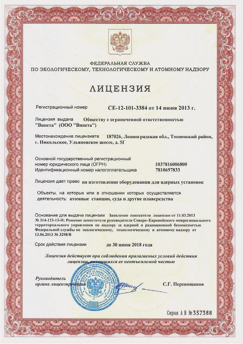
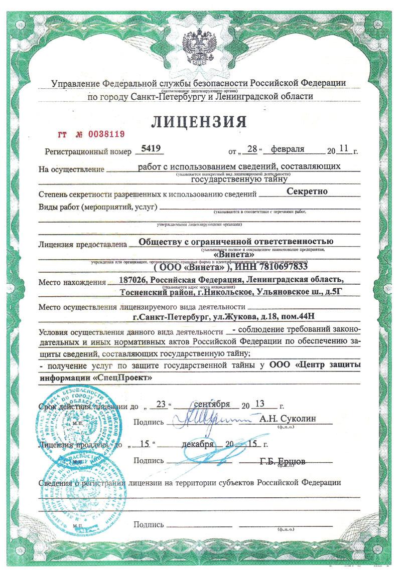
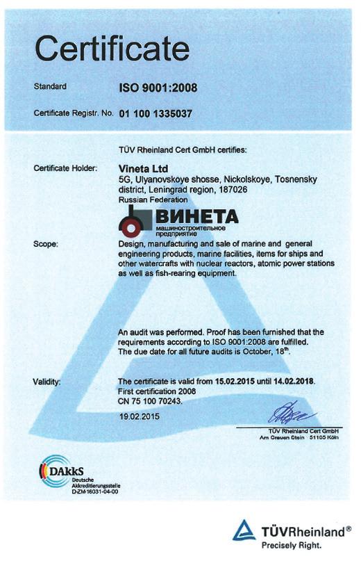
114 LICENSES AND CERTIFICATES LICENSES AND CERTIFICATES 114

115 LICENSES AND CERTIFICATES LICENSES AND CERTIFICATES 115
RESOLUTION MEPC.205(62) Adopted on 15 July GUIDELINES AND SPECIFICATIONS FOR ADD-ON EQUIPMENT FOR UPGRADING RESOLUTION
 Adopted on 15 July GUIDELINES AND SPECIFICATIONS FOR ADD-ON EQUIPMENT FOR UPGRADING RESOLUTION") MEPC.60(33)-COMPLIANT OIL FILTERING EQUIPMENT MEPC.60(33)-COMPLIANT OIL FILTERING EQUIPMENT MEPC 62/24/Add.1 Annex 24, page 1 ANNEX 24 RESOLUTION MEPC.205(62) 2011 GUIDELINES AND SPECIFICATIONS FOR ADD-ON
MEPC.60(33)-COMPLIANT OIL FILTERING EQUIPMENT MEPC.60(33)-COMPLIANT OIL FILTERING EQUIPMENT MEPC 62/24/Add.1 Annex 24, page 1 ANNEX 24 RESOLUTION MEPC.205(62) 2011 GUIDELINES AND SPECIFICATIONS FOR ADD-ON
Technical Data Series 1204E-E44TA. Basic technical data. Performance
 Technical Data 1200 Series 1204E-E44TA Industrial Open Power Unit (IOPU) 74.5 kw @ 2200 Basic technical data Number of cylinders.....................................................4 Cylinder arrangement...................................
FUSES PN22 SERIES Technical description and user manual
 "QUARTZ" LLC FUSES PN SERIES Technical description and user manual UITSG. 67435.008 ТО Zaporizhzhia, Ukraine . Purpose.. PN- series fuses, manufactured by "Quartz" LLC in accordance with TU U 3.-97460-06-98
Plate Heat Exchangers
 Plate Heat Exchangers General Plate heat exchangers are used wherever thermal energy (heat) has to be transferred from one fl uid to another. The advantage is that they can maintain the fl uid temperature
XVM. Vertical, Multi-Staged Stainless Steel Pumps FEATURES APPLICATIONS
 Vertical, Multi-Staged Stainless Steel Pumps FEATURES The pump is a non-self-priming vertical multistage centrifugal pump coupled to a standard motor. Inlet and outlet are located at the bottom at the
HYDRODYNAMIC FUEL EMULSIFER TRGA-3G INSTALLATION, OPERATION, MAINTENANCE MANUAL
 HYDRODYNAMIC FUEL EMULSIFER TRGA-3G TRGA-3G-04S INSTALLATION, OPERATION, MAINTENANCE MANUAL 2014. Gogol's street, 405, Cherkassy, 18005, Ukraine. S.E.A.P.P. Andrey Ruban I.T.N. 2274725715 +380 472 313396,
CENTRIFUGAL SUBMERSIBLE ELECTRIC PUMPS OF GNOM TYPE
 CENTRIFUGAL SUBMERSIBLE ELECTRIC PUMPS OF GNOM TYPE APPLICATION Electric pump of Gnom type is intended for pumping of contaminated waters with the temperature up to о С (Version Tr up to 0 о С), density
Technical Data TWG2A TWG3A Series. Diesel Engine - ElectropaK rev/min. Basic technical data
 Technical Data 4000 Series Diesel Engine - ElectropaK Basic technical data Number of cylinders...................................................12 Cylinder arrangement..........................................
@Perkins. Technical Data
 Technical Data 1100C Series ElectropaK Basic technical data Number of cylinders..................................................... 6 Cylinder arrangement.............................................
Tanker Operator Hamburg Conference Cases of increased wear due to Cat Fines avoidable by on-board fuel condition
 Tanker Operator Hamburg Conference 2015 Cases of increased wear due to Cat Fines avoidable by on-board fuel condition monitoring Dr. Frank Bernier Director Sales and Marketing Background Information Cat
TEAMTEC INCINERATORS Market leaders since More than units sold worldwide
 TEAMTEC INCINERATORS Market leaders since 1972 - More than 11 000 units sold worldwide OG120C. Capacity: 190.000 kcal/h (220 kw). TEAMTEC Incinerator model OG120C The smallest incinerator in our range.
Data sheet. Page: 1 / 5. ETL GGSAV11D BKSBIE3 Inline pump. Operating data. Design
 Data sheet Page: 1 / 5 Operating data Requested flow rate Operating data determined for maximum inlet pressure Requested developed head 15.00 m Pumped medium Ambient air temperature 20.0 C Fluid temperature
Oil in Water Measurement Associated with the Shipping Industry
 Oil in Water Measurement Associated with the Shipping Industry Axel A. Schmidt Research and Development Deckma Hamburg GmbH Deckma Hamburg GmbH Selling and manufacturing oil-in-water monitors since more
Industrial automatic self-cleaning filters made in stainless steel AISI 316
 Industrial automatic self-cleaning filters made in stainless steel AISI 316 FilBlue Introduction The automatic industrial selfcleaning filters are designed to remove all suspended solids from surface water
VARIO. VARIO Separation of fine dust particles. The VARIO series is particularly suitable for separation of fine dust.
 VARIO VARIO Separation of fine dust particles The VARIO series is particularly suitable for separation of fine dust. The VARIO units are of modular construction in order to meet different requirements,
2-component PU foam dispensing machine
 2-component PU foam dispensing machine We would like to represent the technology and equipment for dosing, mixing and further automatic applying of the 2-component polyurethane foam, used for the doors
UNITED STATES ENVIRONMENTAL PROTECTION AGENCY OFFICE OF TRANSPORTATION AND AIR QUALITY ENGINE INTERNATIONAL AIR POLLUTION PREVENTION CERTIFICATE
 UNITED STATES ENVIRONMENTAL PROTECTION AGENCY OFFICE OF TRANSPORTATION AND AIR QUALITY ENGINE INTERNATIONAL AIR POLLUTION PREVENTION CERTIFICATE Manufacturer: Engine Family: Certificate Number: AB VOLVO
Strainer BOA-S PN 6/16/25 DN Type Series Booklet
 Strainer PN 6/16/25 DN 15-400 Type Series Booklet Legal information/copyright Type Series Booklet All rights reserved. The contents provided herein must neither be distributed, copied, reproduced, edited
DETAILED EQUIPMENT SPECIFICATION MRO-4 SERIES REVERSE OSMOSIS SYSTEMS
 5356 Hillside Avenue Indianapolis, IN 46220 P: +1 888-56-Water (569-2837) F: +1 317-255-4727 info@nancrede.com www.nancrede.com DETAILED EQUIPMENT SPECIFICATION MRO-4 SERIES REVERSE OSMOSIS SYSTEMS 1.0
UNITED STATES ENVIRONMENTAL PROTECTION AGENCY OFFICE OF TRANSPORTATION AND AIR QUALITY ENGINE INTERNATIONAL AIR POLLUTION PREVENTION CERTIFICATE
 UNITED STATES ENVIRONMENTAL PROTECTION AGENCY OFFICE OF TRANSPORTATION AND AIR QUALITY ENGINE INTERNATIONAL AIR POLLUTION PREVENTION CERTIFICATE Manufacturer: Engine Family: Certificate Number: AB VOLVO
Air Master BCP. Pool air handling units. Optimized energy consumption Electronic control. Description. Principle schemes
 Cooling capacity: Heating capacity: 92,1 to 179,9 kw 69, to 148,7 kw Heating and dehumidification of covered pools Optimized energy consumption Electronic control Description Principle schemes The range
TAG3. Diesel engine - ElectropaK. Series kwm 1500 rpm. Basic technical data. Ratings. Total weight of ElectropaK
 1105 kwm Standby @ 1500 rpm Diesel engine - ElectropaK 4000 Series Basic technical data Number of cylinders............................................................8 Cylinder arrangement................................................
Datasheet MATRE Foam Inductors. Datasheet for MATRE Foam Inductors. 1 Contents
 Datasheet for MATRE Foam Inductors 1 Contents 2 General product description... 3 3 General installation guide... 3 4 Product dimensions and performance... 3 4.1 Standard bronze housing design - threaded...4
Watertreatment. Landbased Farming. Weedfilter. Catvis WATER I NTAKE R ECIRCULATION S YSTEM
 Weeds Drum Cartridge UV-unit WATER I NTAKE Screen Pump Weed Drum UV-unit Climate control H ATCHERY N URSERY B ROODSTOCK O NGROWING Oxygen reactor Denitrification Control unit R ECIRCULATION S YSTEM Ozonation
@Perkins. Technical Data Series TAG1A TAG2A TAG3A. Diesel Engine - Electropak. Basic technical data
 Technical Data Basic technical data Number of cylinders.................................................... 6 Cylinder arrangement................................... Vertical, In line Cycle....................................4
KARL SCHNELL GRINDER SPECIFICATION: KS Process Automat B 22 Type l
 KARL SCHNELL GRINDER SPECIFICATION: KS Process Automat B 22 Type 250 300l Execution - total volume mixer bowl approx. 380 l, nominal volume approx. 300 l - stationary design, with four height adjustable
Technical File D3*GL*E3
 Technical File D3*GL*E3 According to Revised MARPOL Annex VI and NOx Technical Code 2008 Manufacturer: Engine Family: GL family approval no. Engine Type: AB Volvo Penta D3 14252-10 HH D3-200I-D, D3-200A-D
Stainless Steel Vertical Multistage Pump CONTENTS
 , EVMUG/L - V ertic ca l Multistage s D ata Book 6Hz / EVMU(G)(L) CONTENTS SECTION PAGE FEATURES 2 TYPICAL APPLICATIONS 3 MODEL DESIGNATION 4 PRODUCT SPECIFICATIONS 1 2 5 EVMU(G)(L)32 - EVMU(G)(L)64 6
Vertical, Multi-Staged Stainless Steel Pumps
 Vertical, Multi-Staged Stainless Steel Pumps www.masflo.fr FEATURES The XVM pump is a non-self-priming vertical multistage centrifugal pump coupled to a standard motor. Inlet and outlet are located at
Data sheet. Omega B GB G F Version no.: 1. Operating data. Design. Driver, accessories. Clean water. Actual developed head 57.
 Data sheet Item no.: 3700 Page: 1 / 5 Operating data Pumped medium Water Actual flow rate 415.38 m ³/h Clean water Actual developed head 57.81 m Not containing chemical and Efficiency 82.3 % mechanical
abc CPD7948/075 Rotors, rotor shafts and rotor casings are coated with an anti-corrosive and anti wear coating to prolong element life and efficiency.
 CPD7948/075 Specification Oil-Free, Air Cooled, Rotary Screw Compressors - Dryclon Range Models D75, D90, D110, D132, D150 (50Hz) D55, D75, D90, D110, D150 (60Hz) COMPRESSOR PACKAGE An enclosed two stage
Technical Data 4008TAG 4008TAG1 4008TAG Series. Diesel Engine - ElectropaK
 Technical Data 4000 Series Diesel Engine - ElectropaK Basic technical data Number of cylinders..................................................... 8 Cylinder arrangement.............................................
ILN, ILNC. In Line vertical pumps. ILN single suction ILN double suction ILNC. 1. Fields of Application. 3. Design. 4. Designation. 2.
 Type series booklet CTI-2600/04 [04-2017] ILN, ILNC In Line vertical pumps ILN single suction ILN double suction ILNC sizes 65/ to 250/... sizes 300/ all sizes 1. Fields of Application Suitable for a wide
Technical File D16-MH*CCS*E3E2C1. According to Revised MARPOL Annex VI and NOx Technical Code Contents
 Technical File D16-MH*CCS*E3E2C1 According to Revised MARPOL Annex VI and NOx Technical Code 2008 Manufacturer: Engine Family: Family approval no. Engine Type: AB Volvo Penta D16-MH GB10T00020-3 Engine
GMP-Type. Key Features: Integrated Motor-Pump Units
 Integrated Motor-Pump Units GMP-Type Key Features: Direct coupling between motor and pump Rotation: Right (viewed from shaft end) Electric motor mounting type: special B3-B14 (IEC 34-7) Rated Voltage:
TRUNNION MOUNTED METAL SEATED BALL VALVES
 TRUNNION MOUNTED METAL SEATED BALL VALVES HIGH PERFORMANCE BALL VALVES FOR SEVERE SERVICES PROCESS VALVES STANDARD FEATURES FOR SIDE ENTRY & BOTTOM ENTRY DESIGN 1. Trunnion Mounted The ball is trunnion
Check Valves DN PN 80, 100, 160
 47 DN 300-1000 PN 80, 100, 160 Designed to automatically prevent back flow of working medium, when transmitting non-aggressive natural gas and other non-aggressive media at the temperature ranged -60 C
SAFETY FUSES PP57U SERIES Technical description and user manual
 "QUARTZ" LLC SAFETY FUSES PP57U SERIES Technical description and user manual UITSG 674 351.010 RE Zaporizhzhia, Ukraine 2 1. Purpose Series PP57U Fuses (hereinafter "fuses") are intended for protection
8 Technical Reference
 8 Technical Reference Contents 8.1 Technical data 122 8.2 Connection list 125 8.3 Interface description 126 8.3.1 General 126 8.3.2 Definitions 126 8.3.3 Component description and signal processing 127
Technical Data. 400 Series 403D-15G. ElectropaK
 Technical Data 400 Series 403D-15G ElectropaK Basic technical data Number of cylinders.................................................... 3 Cylinder arrangement.................................... Vertical
Automatic Back-Flushing Filter for Process Technology AutoFilt RF3.
 Automatic Back-Flushing Filter for Process Technology AutoFilt RF3. AutoFilt RF3: So automatic, The Challenge Particle contamination in process water and other operating fluids accelerates the rate of
Technical File and Copy of United States Environmental Protection Agency (EPA) Statement of Compliance
 Statement of Compliance") Technical File and Copy of United States Environmental Protection Agency (EPA) Statement of Compliance MARINE DIESEL ENGINES D4.2L 230 (4.2 MS 230 and 4.2 MI 230 Model) IMPORTANT: To comply with regulations
Technical File and Copy of United States Environmental Protection Agency (EPA) Statement of Compliance MARINE DIESEL ENGINES D4.2L 230 (4.2 MS 230 and 4.2 MI 230 Model) IMPORTANT: To comply with regulations
TUNGUS. POWDER FIRE-EXTINGUISHING MODULE MPP(N)-5-I-GE-U2 Passport and Manual instructions
-5-I-GE-U2 Passport and Manual instructions") TUNGUS Istochnik Plus, closed joint stock company 659322, 1, Socialisticheskaya St., Biysk, Altay region, Russia, Tel.: +73854-30-19-32, 30-58-59 www.antifire.org antifire@inbox.ru POWDER FIRE-EXTINGUISHING
TUNGUS Istochnik Plus, closed joint stock company 659322, 1, Socialisticheskaya St., Biysk, Altay region, Russia, Tel.: +73854-30-19-32, 30-58-59 www.antifire.org antifire@inbox.ru POWDER FIRE-EXTINGUISHING
Process Inline Filter Protective filter PLF2-9HF
 Process Inline Filter Protective filter PLF2-9HF Specifications Nominal size: DN 300 - DN 600 Q s max: 3000 m 3 /h p s max: 16 bar Filtration ratings: 1-90 µm 1. GENERAL Product description Protective
Container MBW12K90MC Thursday 25 Jan 2007
 Cylinder Oil Drain Analysis & Engine Performance Report Samples Landed : SINGAPORE - 26 Jan 7 Received at Analysis Labs : 29 Jan 7 Engine :SAMSUNG MAN B&W 12K9MC MCR : 74,64 bhp @ 94 rpm Next Samples Due
VM, VMC, VMN. Vertical Multistage Centrifugal Pump, 60Hz
 VM, VMC, VMN Vertical Multistage Centrifugal Pump, 60Hz Approvals CERTIFICATE IQNet and SQS hereby certify that the organisation Swiss Pump Company AG 3645 Thun-Gwatt Switzerland Whole Company Design,
DETAILED EQUIPMENT SPECIFICATION MHC SERIES WATER SOFTENERS
 2227 South Street P.O. Box 044170 Racine, Wisconsin 53404-7003 Phone: 262-681-1300 Fax: 262-681-1318 www.marlo-inc.com DETAILED EQUIPMENT SPECIFICATION MHC SERIES WATER SOFTENERS 1.0 SCOPE 1.1 Provide
1104D-44TG2 1104D-44TG kwm 1500/1800 rpm. ElectropaK. Series. Basic technical data. Performance
 1104D-44TG2 1104D-44TG3 56.6-69.0 kwm (Gross) @ 1500/1800 rpm ElectropaK 1100 Series Basic technical data Number of cylinders.....................................................4 Cylinder arrangement...................................
Since 1962 TEST BENCHES FOR SHUT OFF & CONTROL VALVES. Catalogue 2015
 Since 1962 TEST BENCHES FOR SHUT OFF & CONTROL VALVES Catalogue 2015 CONTENT Equipment for testing: Horizontal test benches for shut-off valve 4 PKTBA-S-5-1000/2000, PKTBA-S-5-1200/3000, PKTBA-S-5-1400/4000
Continuous Baseload. Prime Power
 Technical Data 4000 Series Diesel Engine - Electrounit Basic technical data Number of cylinders..................................................... 8 Cylinder arrangement.............................................
Filters and Filtration Equipments
 Filters and Filtration Equipments Resume 1. - HSC Series Self cleaning filters. 2. - HSBI Self cleaning filters. 3. - HSBIL Series Self cleaning filters. 4. - HSBIA Series self cleaning filters. 5. - HFC
OIL TREATMENT ARRAS MAXEI
 I-BETH13GB-A page 1/5 TECHNICAL DESCRIPTION OF THE STANDARD PLANTS TYPE MAS 8000 110kW 500m 3 /h SUMMARY: Principle of operation 2 Main characteristics 2 Components of the plant 2 Description of the plant
Filtration Technology ISO 9001 Qualified
 Micro-Filter & Filter Water Separator Gasoline, Diesel Oil, Jet Fuel AIRPORT TERMINALS PIPELINE REFINERY Filtration Technology ISO 9001 Qualified 1 Filtration & Separation Filter Water Separator APPLICATIONS
ANNEX 23. RESOLUTION MEPC.187(59) Adopted on 17 July 2009
 Adopted on 17 July 2009") RESOLUTION MEPC.187(59) Adopted on 17 July 2009 AMENDMENTS TO THE ANNEX OF THE PROTOCOL OF 1978 RELATING TO THE INTERNATIONAL CONVENTION FOR THE PREVENTION OF POLLUTION FROM SHIPS, 1973 (Amendments to
RESOLUTION MEPC.187(59) Adopted on 17 July 2009 AMENDMENTS TO THE ANNEX OF THE PROTOCOL OF 1978 RELATING TO THE INTERNATIONAL CONVENTION FOR THE PREVENTION OF POLLUTION FROM SHIPS, 1973 (Amendments to
Technical Data. 400 Series 403D-11G. ElectropaK
 Technical Data 400 Series 403D-11G ElectropaK Basic technical data Number of cylinders.................................................... 3 Cylinder arrangement.................................... Vertical
Pressure: Max working 8 bar (116 psi) (acc. to NFPA T ) Burst 16 bar (232 psi) (acc. to NFPA T ) Buna-N (FKM on request)
 (acc. to NFPA T ) Burst 16 bar (232 psi) (acc. to NFPA T ) Buna-N (FKM on request)") HYDRAULIC FILTRATION Return filters, tank top mounting, inside-to-outside filtration Technical Information Pressure: Max working 8 bar (116 psi) (acc. to NFPA T 3.10.5.1) Burst 16 bar (232 psi) (acc. to
HYDRAULIC FILTRATION Return filters, tank top mounting, inside-to-outside filtration Technical Information Pressure: Max working 8 bar (116 psi) (acc. to NFPA T 3.10.5.1) Burst 16 bar (232 psi) (acc. to
DETAILED EQUIPMENT SPECIFICATION MDAS SERIES DEALKALIZERS
 5356 Hillside Avenue Indianapolis, IN 46220 P: +1 888-56-Water (569-2837) F: +1 317-255-4727 info@nancrede.com www.nancrede.com DETAILED EQUIPMENT SPECIFICATION MDAS SERIES DEALKALIZERS 1.0 SCOPE 1.1 Provide
Appendix B-6. Mechanical Equipment Design Calculation
 Appendix B-6 Mechanical Equipment Design Calculation APPENDIX B.6 Mechanical Equipment Calculation (1) Design Flow 1. Design Conditions M3/day M3/hour M3/min M3/sec Design Maximum Daily Flow Design Maximum
AUTOMATED SELECTION OF THE MATERIAL A FAN BLADE PS-90A
 AUTOMATED SELECTION OF THE MATERIAL A FAN BLADE PS-90A D. A. Akhmedzyanov, A. E. Kishalov, K. V. Markina USATU Ufa State Aviation Technical University, Russia Keywords: GTE, fan blade, composite material,
MIB 303 AC Separation System, Module. System Reference. Product No Aug V1. Printed Book No. Alfa Laval Marine & Power
 MIB 303 AC Separation System, Module System Reference Product No. 1765785-80 Printed Book No. Aug 1997 1810598-02 V1 Alfa Laval Marine & Power Alfa Laval reserve the right to make changes at any time without
General In-line four stroke diesel engine with direct injection. Rotation direction, counterclockwise viewed towards flywheel
 Important This Technical Data Sheet and the corresponding Installation Instructions provide important information to ensure the installed engine will operate according to the design specification in the
Automatic back-flushing filter AutoFilt RF4
 Automatic back-flushing filter AutoFilt RF4 RF4-1 RF4-2 Specifications Nominal size: G1 G 1½ Q max: 220 l/min p max: 16 bar Filtration ratings: 30 1000 µm 1. GENERAL Product description Self-cleaning automatic
EXPERIMENTAL RESEARCH AND OPTIMIZATION OF BREST-OD-300 MCP MODEL PERFORMANCE IN A LEAD COOLANT
 EXPERIMENTAL RESEARCH AND OPTIMIZATION OF BREST-OD-300 MCP MODEL PERFORMANCE IN A LEAD COOLANT A.V. Beznosov, P.A. Bokov, O.I. Buzina, A.D. Zudin, A.V. Lvov, T.M. Semayeva, N.D. Trushkov (NNSTU n.a. R.E.
Indirect evaporative air conditioning 100% outside air FACTORY INSTALLATION (CW-160)
") FACTORY INSTALLATION (CW-160) Indirect evaporative air conditioning 100% outside air About Climate Wizard Climate Wizard s unique indirect evaporative heat exchange core provides hyper-efficient cooling
FACTORY INSTALLATION (CW-160) Indirect evaporative air conditioning 100% outside air About Climate Wizard Climate Wizard s unique indirect evaporative heat exchange core provides hyper-efficient cooling
@Perkins. Technical Data. 400 Series 403D-11G. ElectropaK
 Technical Data @Perkins 400 Series 403D-11G ElectropaK Basic technical data Number of cylinders.................................................... 3 Cylinder arrangement....................................
Recommendation for petroleum fuel treatment systems for marine diesel engines
 (July 2017) Recommendation for petroleum fuel treatment systems for marine diesel engines I Recommendation for the treatment of fuel oil on board ships 1 Application The following requirements should apply
Dewatering Submersible sewage pumps
 Series description Wilo-Drain TP 80/TP 100 Equipment/function Thermal motor monitoring Leakage detection in the motor ATEX-certified Sheath current cooling Materials Pump housing: PUR Impeller: PUR Shaft:
Technical Data 404D-22
 Technical Data 404D-22 IOPU Basic technical data Number of cylinders..................................................... 4 Cylinder arrangement....................................verticle in line Cycle............................................................
Technical Data TRG TRG TRG Series
 Technical Data 4000 Series Diesel Engine Basic technical data Number of cylinders................................................... 16 Cylinder arrangement.......................................... 60
FilterMax DF. Modular dust multi purpose collector. Models
 Modular dust multi purpose collector FilterMax DF is a efficient and compact solution to your dust and fume problems. FilterMax DF handles the air polution from metal industries as well as non explosive
TPV Variable Displacement Closed Loop System Axial Piston Pump HY-TRANS THE PRODUCTION LINE OF HANSA-TMP HT 16 / M / 501 / 1009 / E
 HYDRAULIC COMPONENTS HYDROSTATIC TRANSMISSIONS GEARBOXES - ACCESSORIES HY-TRANS THE PRODUCTION LINE OF HANSA-TMP Via M. L. King, 6-41122 MODENA (ITALY) Tel: +39 059 415 711 Fax: +39 059 415 729 / 059 415
DETAILED EQUIPMENT SPECIFICATION HIGH PURITY LABORATORY WATER SYSTEM
 5356 Hillside Avenue Indianapolis, IN 46220 P: +1 888-56-Water (569-2837) F: +1 317-255-4727 info@nancrede.com www.nancrede.com DETAILED EQUIPMENT SPECIFICATION HIGH PURITY LABORATORY WATER SYSTEM 1.0
Automated Globe Valves. BOA-H Mat P PN 16/25 DN Type Series Booklet
 Automated Globe Valves BOA-H Mat P PN 16/25 DN 20-150 Type Series Booklet Legal information/copyright Type Series Booklet BOA-H Mat P All rights reserved. The contents provided herein must neither be distributed,
HAWLE-AIR RELEASE VALVES
 HAWLE-AIR RELEASE VALVES HAWLE-AIR RELEASE VALVES Contents: Dimensions of Air Release Valve Page 2 Why use Air Release Valves? Page 3 Application: Potable water Air Release Valves, DN 1" - DN 2" Page 4
Data sheet. Page: 1 / 5 ETN GG A 11GA201502B. Operating data. Design. Requested developed head m. Efficiency 74.
 Data sheet Page: 1 / 5 Operating data Requested flow rate 160.00 m³/h Actual flow rate 159.85 m³/h Operating data determined for maximum inlet pressure Actual developed head 20.96 m Requested developed
Filtrec elements are tested according to ISO 2941, ISO 2942 and ISO 23181
 Common HYDRAULIC FILTRATION Side wall mounting suction filters Technical Information Connection Ports: 1-1 1/4-1 1/2 BSP (other thread options on request) 1 1/2 SAE J518-3000/M12 Housing Materials: Cover:
BILGE WATER DEOILING SAFE, RELIABLE, ECONOMICAL MULTI-PHASE EMULSION BREAKER MPEB
 BILGE WATER DEOILING SAFE, RELIABLE, ECONOMICAL MULTI-PHASE EMULSION BREAKER MPEB MPEB 10 What is bilge water? Bilge water is the result of leakages, of de - watering processes from sedimentation and sludge
Filtration Ft-Line 34. Ck-Line 38. Cp-Series 42. FilterMax 46. Cintropur filtration 51. Cartridge housings
 0. 20. Ft-Line 34. Ck-Line 38. Cp-Series 42. FilterMax 46. Cintropur filtration 5. Cartridge housings 57. Filter cartridges 6. Containers 62. Big cartridge housings 63. Big filter cartridges 9 Ft-Line
Data sheet. Customer item no.: Communication dated: Number: ES Doc. no.: Item no.: 100 Quantity: 1 Date: 19/03/2015 Page: 1 / 6
 Data sheet Item no.: Page: 1 / 6 Operating data Operating data determined for maximum inlet pressure Pumped medium Water Clean water Not containing chemical and mechanical substances which affect the materials
Profluid and Gap-type tube filters. Automatic filters
 and Gap-type tube filters Automatic filters and Gap-type tube filters the efficient answer for multi-purpose applications Identical technology two different cleaning principles Automatic filters such as
Technical Circular. No.: 025 Date: 6 th November 2014
 Technical Circular No.: 025 Date: 6 th November 2014 To Whomsoever it may concern Subject: UPDATE BASED ON OUTCOME OF 67 TH SESSION OF THE MARINE ENVIRONMENT PROTECTION COMMITTEE HELD AT IMO HEADQUARTERS
DETAILED EQUIPMENT SPECIFICATION MR SERIES WATER SOFTENERS
 5356 Hillside Avenue Indianapolis, IN 46220 P: +1 888-56-Water (569-2837) F: +1 317-255-4727 info@nancrede.com www.nancrede.com DETAILED EQUIPMENT SPECIFICATION MR SERIES WATER SOFTENERS 1.0 SCOPE 1.1
LDP & LDD series Filter element according to DIN Maximum working pressure up to 6 MPa (60 bar) - Flow rate up to 330 l/min
 - Flow rate up to 330 l/min") Low & Medium Pressure filters LDP & series Maximum working pressure up to 6 MPa (60 bar) Flow rate up to 0 l/min 7 Low & Medium Pressure filters Introduction FILTER SIZING INDEX CALCULATION CORRECTIVE
Low & Medium Pressure filters LDP & series Maximum working pressure up to 6 MPa (60 bar) Flow rate up to 0 l/min 7 Low & Medium Pressure filters Introduction FILTER SIZING INDEX CALCULATION CORRECTIVE
09GDV and 09LDV. Air Cooled Dry coolers and Condensers
 Air Cooled Dry coolers and Condensers Carrier is participating in the Eurovent Certification Programme. Products are as listed in the Eurovent Directory of Certified Products. 09GDV and 09LDV Nominal cooling
Filtration Of Liquids & Gases From Coarse To Submicronic Customized Filtration Solutions Oil Purification Systems
 Filtration Of Liquids & Gases From Coarse To Submicronic Customized Filtration Solutions Oil Purification Systems www.engfilt.com Multi-Use Compact Inline Filters In-Line Filters Up To 6,000 PSI Cartridge
Technical Data Series 1206E-E70TTA. Basic technical data. Performance
 Technical Data 1200 Series 1206E-E70TTA Electropak 150 kwe @ 1800 rpm Basic technical data Number of cylinders.....................................................6 Cylinder arrangement...................................
LINEAR AND ROTATING TYPE AUTOMATIC SELF-CLEANING LIQUID FILTERS
 AUTO-LINE LINEAR AND ROTATING TYPE AUTOMATIC SELF-CLEANING LIQUID FILTERS HiFlux Auto-line is designed as a compact self-cleaning filter Its robust construction makes it suitable for industrial applications
Technical data TWD1643GE
 General Inline four stroke diesel engine with direct injection. Rotation direction, anticlockwise viewed towards flywheel. Turbocharged Number of cylinders 6 Displacement, total in 3 16,12 983,7 Firing
Significance of Each Test. 1. Color (Visual)
") Significance of Each Test 1. Color (Visual) Determine the color of lubricant product by assessing the appearance of transmitted light appearance and intensity, as compare with a standard. Color alone is
Significance of Each Test 1. Color (Visual) Determine the color of lubricant product by assessing the appearance of transmitted light appearance and intensity, as compare with a standard. Color alone is
INDUSTRIAL GENERATORS. steam or overheated water 97/23/CE - P.E.D. certified
 05-0514 INDUSTRIAL GENERATORS steam or overheated water 97/23/CE - P.E.D. certified TECHNIQUE, COMPETENCE, EXPERIENCE OR INDUSTRY The steam and overheated water production cost is a decisive factor for
MDQ MULTI-DISC SCREW PRESS DEHYDRATOR
 MULTI-DISC SCREW PRESS DEHYDRATOR MDQ TSURUMI s TEEBORG Dehydrator with original condensation and dehydration processes giving highly efficient dehydration TEEBORG is the abbreviation of pump with changeable
ViscoSense 3D. Viscosity & Density Measurement Enabling Mass Flow Measurement. Product Bulletin TO BE REALLY 1 SURE
 ViscoSense 3D Viscosity & Density Measurement Enabling Mass Flow Measurement 774 Product Bulletin WWW.VAF.NL TO BE REALLY 1 SURE 1 Introduction Principle of operation Most of the operating costs of a ship
BCV30 DN20 - Blowdown Control Valve Installation and Maintenance Instructions
 4034450/9 IM-P403-15 AB Issue 9 BCV30 DN20 - Blowdown Control Valve Installation and Maintenance Instructions 1. Safety information 2. Application 3. Technical data 4. Operation 5. Installation 6. Rotating
TPV Variable Displacement Closed Loop System Axial Piston Pump THE PRODUCTION LINE OF HANSA-TMP HT 16 / M / 851 / 0813 / E
 HYDRAULIC COMPONENTS HYDROSTATIC TRANSMISSIONS GEARBOXES - ACCESSORIES THE PRODUCTION LINE OF HANSA-TMP Variable Displacement Closed Loop System CONTENTS General Information... Order Code... Manual Control
SS7 SUBMERSIBLE ELECTRIC PUMPS 7
 SS7 TECHNICAL DATA Performance range: flow up to 110 m3/h and max head of 423 m Max. quantity of sand/silt: 50g/m3 Max. ambient temperature: 30 C (50 C available on request) Outlet connection diameter
Oil/Air Cooler Units. Standard series EL Type. Test procedure certified following EN 1048
 COMPLETE OIL / AIR COOLER SYSTEM WITH AXIAL FAN FOR INDUSTRIAL APPLICATIONS. Application These high performance coolers with axial fans are suitable for hydraulic cooling applications with both return
REBCO (RUSSIAN EXPORT BLEND CRUDE OIL) SPECIFICATION GOST
 SPECIFICATION GOST") REBCO (RUSSIAN EXPORT BLEND CRUDE OIL) SPECIFICATION GOST 51858-2002 Characteristics Units Result Test Method Density (Specific Gravity) @ 20 C g /sm 3 0.870 ASTM D5002 Sulphur Content wt.% 1.8 ASTM D4294
REBCO (RUSSIAN EXPORT BLEND CRUDE OIL) SPECIFICATION GOST 51858-2002 Characteristics Units Result Test Method Density (Specific Gravity) @ 20 C g /sm 3 0.870 ASTM D5002 Sulphur Content wt.% 1.8 ASTM D4294
By-pass: 1,7 bar (24.6 psi) setting N.B. Cartridge with integrated bypass valve and antidrainback membrane
 setting N.B. Cartridge with integrated bypass valve and antidrainback membrane") HYDRAULIC FILTRATION Spin-on, tank top return filters Technical Information Pressure: Max working 12 bar (175 psi) (acc. to NFPA T 3.10.17) Burst 20 bar (290 psi) (acc. to NFPA T 3.10.17) Connection Ports:
HYDRAULIC FILTRATION Spin-on, tank top return filters Technical Information Pressure: Max working 12 bar (175 psi) (acc. to NFPA T 3.10.17) Burst 20 bar (290 psi) (acc. to NFPA T 3.10.17) Connection Ports:
Technical Data. ElectropaK
 Technical Data 1100D Series ElectropaK Basic technical data Number of cylinders..................................................... 4 Cylinder arrangement.............................................
TPV Variable Displacement Closed Loop System Axial Piston Pump THE PRODUCTION LINE OF HANSA-TMP HT 16 / M / 852 / 0815 / E
 HYDRAULIC COMPONENTS HYDROSTATIC TRANSMISSIONS GEARBOXES - ACCESSORIES Certified Company ISO 9001-14001 ISO 9001 Via M. L. King, 6-41122 MODENA (ITALY) Tel: +39 059 415 711 Fax: +39 059 415 729 / 059 415