Current Status of the Melcor Nodalization for Atucha I Nuclear Power Plant. Zárate. S.M. and Valle Cepero, R.
|
|
|
- Christian Riley
- 6 years ago
- Views:
Transcription
1 Current Status of the Melcor Nodalization for Atucha I Nuclear Power Plant Zárate. S.M. and Valle Cepero, R. presentado en USNRC Cooperative Severe Accident Research Program (CSARP), Maryland, EE. UU., 7-9 mayo 2001
2 CURRENT STATUS OF THE MELCOR NODALIZATION FOR ATUCHA I NUCLEAR POWER PLANT Zárate. S.M. and Valle Cepero, R. Nuclear Regulatory Authority Argentina OUTLINE Goal of presentation Development of a model for Atucha I with MELCOR Status Future Activities GOAL OF PRESENTATION Brief of overview of Argentina NRA activity with MELCOR code The following activities, with MELCOR code, have been continued in NRA as part of the project on Severe Accidents. In 1997 a global agreement was signed with NRC, therefore MELCOR is used at Argentina since The first works were in order to make well know the range of physical phenomena and thermal hydraulics response that MELCOR code models and learns to apply it. DEVELOPMENT OF A MODEL FOR ATUCHA I WITH MELCOR Objective is to analyze accident progression in Atucha I with MELCOR. A model for Atucha I is being developed in two parts: One of them involves reactor pressure vessel and reactor coolant system The other involves containment aspects. Atucha I has a particular design (prototype). The specific features are laid in both Reactor Pressure Vessel and Containment. In order to evaluate the response of the model: Two accidental sequences will be considered: Station Blackout (High Pressure Scenario) LB LOCA (Low Pressure Scenario) Up to now the model is being improved under a Station Blackout accidental sequence. 725
3 GENERAL PLANT DESCRIPTION Atucha I Nuclear Power Plant, has been designed and constructed by SIEMMES Company of Erlangen, Germany. The Atucha I, object of this study, is a nuclear power plant with a pressure heavy water reactor (PHWR) which is fuelled with natural uranium as well as slightly enriched uranium, reactor uses heavy water like coolant and moderator, it is on line refueled. The thermal power of 1170 MW, with nominal output electrical power of 357 MW. The reactor coolant system has two parallel loops, each of them having a circulation pump, a vertical steam generator with U tubes and the necessary connecting pipes. One of loops has a pressurizer with safety valves. Both primary system equipment and the accumulators within the emergency core coolant system are enclosed in a containment building. REACTOR COOLANT SYSTEM AND MODERATOR SYSTEM REACTOR PRESSURE VESSEL 2 - STEAM GENERATORS 3 - REACTOR COOLANT PUMPS 4 - PRESSURIZER 5 - MODERATOR PUMPS 6 - MODERATOR COOLERS 7 - EMERGENCY COOLING SYSTEM INLET 8 - PRESSURE AND INVENTORY CONTROL SYSTEM 9 - SHUTDOWN COOLING SYSTEM (MODERATOR) 10 - SECONDARY SIDE SAFETY VALVES 11 - PRESSURIZER RELIEF TANK 12 - PRIMARY SIDE SAFETY VALVES 13 - SECONDARY INLET LIGHT WATER 14 - RESIDUAL HEAT REMOVAL SYSTEM 15 - SERVICE COOLING WATER SYSTEM FOR PLANT SECURED 726
4 REACTOR REACTOR PRESSURE VESSEL AND INTERNALS (1) Reactor Pressure Vessel. (2) Lower Filler Pieces. (3) Moderator Tank. (4) Moderator Piping. (5) Coolant Channel. (6) Control Rod Guide Tube. (7) Boron Inlet Nozzle. (8) Heavy Water Outlet Nozzle. (9) Moderator Tank Closure Head. (10) Reactor Pressure Vessel Closure Head. (11) Upper Filler Pieces. (12) In Core-Instrumentation Nozzle. (13) Heavy Water Inlet Nozzle. The reactor pressure vessel (RPV) and the reactor coolant system are connected by the nozzles number 8, and 13. The reactor coolant flows inside RPV by the nozzle 13, in a downwards direction, between RPV and Moderator Tank. Thus RPV and Moderator Tank form the annulus for the in - flowing coolant. The reactor coolant reaches the lower plenum and flows inside the coolant channels in an upward direction through the 253 channels where the fuel assembly is located. The lower filler pieces and the upper filler pieces are provided in the RPV in order to reduce the heavy water inventory required. The upper filler pieces constitute the biological shield during shutdown of reactor. The control rod is moved into the tube guide 6. The tube guide is arranged slanting to make possible the refuelling procedure. The reactor contains 24 black (absorbers made of hafnium) and 5 grey steel control rods. One of the main design features of the RPV in Atucha -I is the moderator tank. The moderator system consists of two identical loops operating in parallel. Each loop comprises a moderator cooler, a moderator pump, and the interconnecting piping with valves. The moderator system performs various functions depending on the operating mode of the reactor 1- During normal operation the moderator system maintains the moderator at lower temperature than that of the reactor coolant. 2- During shutdown of the reactor, the moderator system is switched over to the residual heat removal position by means of the moderator valves. 3- During emergency core cooling the moderator serves a high-pressure core re-flooding and coolant system. The emergency core cooling position is similar to that of the residual heat 727
5 removal, but additionally, water is injected into the hot legs of the reactor coolant loops and into the upper plenum of the RPV. The residual heat removal chain connected to the moderator coolers during emergency core cooling is the same as during residual heat removal. All systems of the residual heat removal chain are of a consistent two - loop desing. THE PRESSURIZER The pressurizer system is connected to one reactor coolant loop and basically comprises the pressurizer with the electric heaters, the surge line, the spray line with the safety valves. The function of the pressurizer system is to maintain the appropriate pressure in the reactor coolant system in order to prevent boiling of the coolant under all operating conditions (principle of the pressurized reactor), and to avoid or limit the pressure variations caused by volume fluctuations during load changes. The pressurizer is partly filled with satured water and partly with steam. Its available volume is 40 m 3. It has three relief and safety valves, whose set point is 125 kgf/cm 2 for one of them and 132 kgf/cm 2 for the other two. NODALIZATION SCHEME FOR THE REACTOR COOLANT SYSTEM WITH A MELCOR General Nodalization of the RCS with the Control Volume Package (CVH). 728
6 The basic plant nodalization can be seen in the figure, concerning the control volume hydrodynamics package (CVH) of the pressure vessel and reactor coolant system. The pressure vessel was divided into nine volumes, three of this volumes belong to moderator system (CV140, 141, 142), and the other six represented the downcomer (CV111,112,113), lower plenum (CV120), core (CV130), upper plenum (CV150) as well as the necessary communications among them, with positive flows, in accordance with the usual directions in non accidental situations. THE MODERATOR SYSTEM In spite of the fact the moderator system is practically independent we must take into account that the reactor coolant system and the moderator system are connected by the pressure equalization openings of the moderator tank closure head. Therefore in a first phase of the nodalization the moderator system has been considered of independent manner from another control volume. In a second phase of the nodalization, the moderator system will be linked to control volume number 150 which represents the upper plenum. In this case, the area for the flow path will be the real area, between moderator tank and upper plenum. At the moment, the moderator tank has been divided in one volume. The volumes 140 and 142 are representing part of the inlet/outlet moderator system pipe. Four tabular functions allow the moderator inlet/outlet simulate with its respective flows and temperature. THE PRESSURIZER It was modelated as a unique volume. This volume is connected from its inferior part to one of the hot legs through a flow path. The coolant volume in the surge line is added to the pressurizer volume. A flow path links the pressurizer with quench tank. The break of the protection membrane of the quench tank, is produced at 5 kgf/cm 2. In this case the coolant falls into sumps of the containment. THE STEAM GENERATOR The primary side of the steam generator has been divided in 5 control volumes, two of them are representing the collectors cameras of inlet and outlet and the others three are representing the U - tube where the primary coolant flow. By the secondary side, three control volumes have been considered, one of them is representing pipe of feedwater part and the third volume is representing the steam collector. The models is very similar to the moderator system model, but in this case two tabular function have been considered in order to simulate the inlet of mass and energy, and others two tabular function which are representing the steam collector and so these functions are simulating the extraction. In the case of simulating a Station Blackout sequence the function which is representing the feedwater injection must be stopped when the electric energy is lost. NODALIZATION SCHEME FOR THE CORE PACKAGE The figure displays the nodalization required by the COR package. It can be observed a disposition in three radial rings and fourteen axial levels, implicating two hydrodynamic volumes CV120 (lower plenum) and CV130 (active zone). 729
7 Core Nodalization One level is representing the lower plenum, which is composed by a unique material (carbon steel with austenitic platinum plating) corresponding to the filler piece. Other level is representing to the metallic plate which serves as the lower fixing level for the coolant channels and the control rod guide tubes. Due to this plate, the coolant flow is divided in two parts, one of them flow inside the coolant channel in an upward direction and the other part flows under this plate. The other twelve axial levels are representing the moderator tank height. The moderator tank accommodates all coolant channels and each of them contains one fuel bundle column. The fuel assemblies are bundles of 36 closely packed fuel rod which are arranged in 4 concentric rings having 1, 6, 12 and 18 fuel rods each, plus an additional structural rod located in the external ring. Each fuel rod consists of a stack of uranium dioxide pellets enclosed by a thin walled zircaloy 4 canning tube. Each fuel assembly, together with the filler body and the closure plug, forms the fuel bundle column. Therefore, the axial levels three and fourteen contains inside its corresponding cell only zircaloy structures but the cells of the rest of the axial level which are representing the active zone are composed by uranium dioxide and zircaloy of the fuel cladding. Then, a group of the geometric parameter has been annexed, such as outer radio of the uranium dioxide pellets and gap between fuel and cladding. In the case of the others structures, has been annexed the thickness corresponding to the filler pieces, the metallic plate in the bottom of the moderator tank and the corresponding to the guide tube of the control rods. The thickness for the lower head has been declared too. 730
8 The particular configuration of the control rods in Atucha which are made of hafnium is not considered by MELCOR which permits only two option B4C for the BWRs and Ag-In -Cd for the PWRs. Up to now the control rods have not been considered because its mass is negligible. HEAT STRUCTURES FOR THE MODERATOR TANK One of main problems for models the Atucha -I reactor is the great mass of heavy water inside of the moderator tank. In this case and taking into account in normal operating exist a thermal transfer from channels to moderator tank, a thermal transfer through a heat structure located between hydrodynamic volume which is representing to the core and the hydrodynamic volume which is representing to the moderator tank was considered. Heat Structure of one channel related to axial levels of the core model, COR package. 731
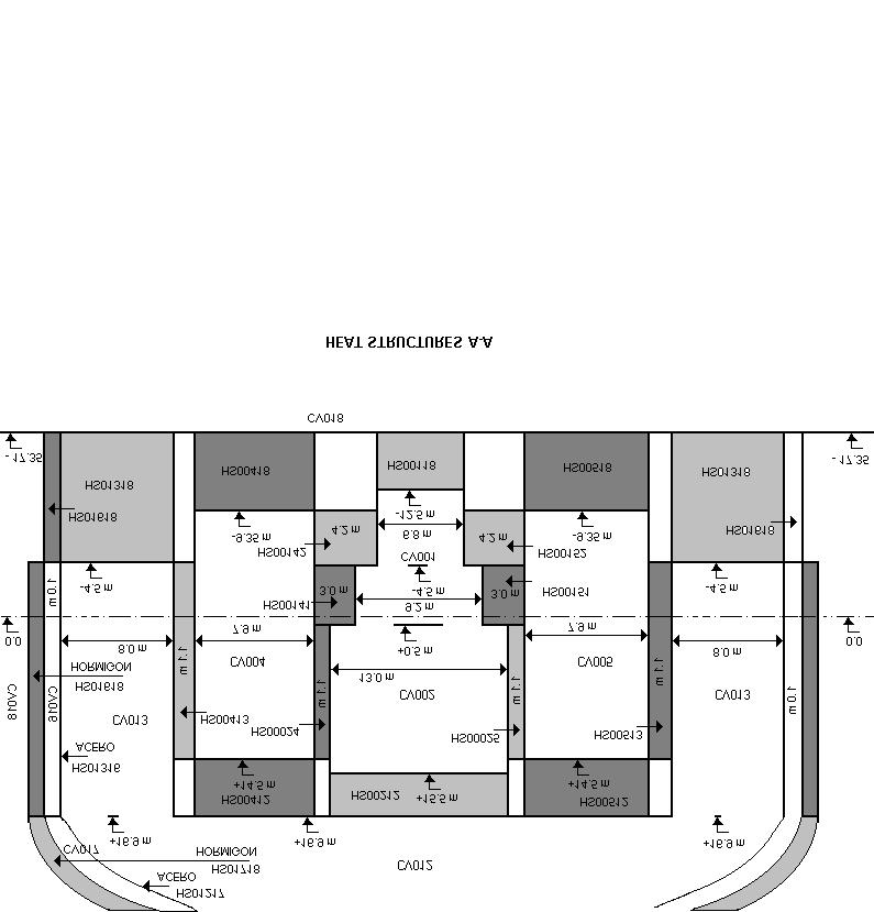
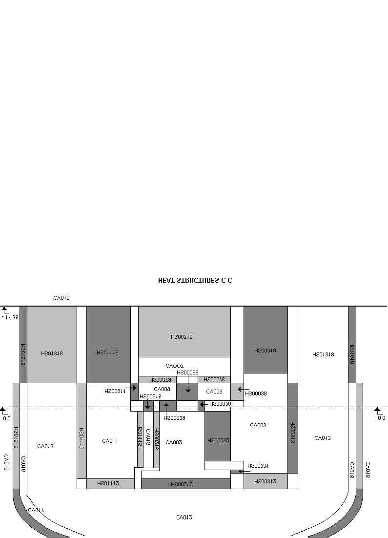
9 HEAT STRUCTURES OF THE REACTOR PRESSURE VESSEL In this case the heat structures have been declared taking into account that materials considered into core has not been considered as heat structure in order to avoid overestimating the mass of the corresponding material. For the structures which are representing the outer wall of the reactor vessel, the option of a insulated boundary condition, was applied. Some many heat structures corresponding to reactor pressure vessel of CNA I. 732
10 RELATIONSHIP BETWEEN COR AND HEAT STRUCTURE PACKAGES In the record CORZjj02 the user has to declare two fields, one of them is the field IHSA which specifies the number corresponding to the heat structure located in the outer radial boundary for an axial level determined. Thereinafter the data are introduced through heat structure package. In the case of the PWR the heat structure located in the outer radial boundary is the corresponding to the baffle. In the case of the Atucha-I are the walls of the 16 channels arranged in the outer ring have been considered as heat structures to be introduced in the field IHSA. Structures between fuel and reactor vessel, 1- fuel, 2- gap, 3-cladding, 4- channel wall, 5- part of the moderator, 6- foils, 7- moderator, 8- wall of the moderator tank, 9- downcomer, 10- reactor vessel wall. HEAT STRUCTURES FOR STEAM GENERATOR, PRESSURIZER AND PRIMARY PIPES In this cases the heat structures have been modeled in the usual mode. At the moment the model considers only a loop but the flow path areas and volume have been duplicated. BUILDING AND STRUCTURES ARRANGEMENTS The Reactor Building, the Reactor Auxiliary Building and the Fuel Storage Building constitute the Controlled Area in which all systems assigned to the nuclear section are installed. The rest of the buildings are located in the Conventional Section of the nuclear power plant. The engineered safety features such as containment SPRAY system or Hydrogen Control System are not present in CNA I. 733


11 The Reactor Building contains the reactor, the reactor coolant system, the moderator system and associated equipment. REACTOR BUILDING Double containment type (KWU) REACTOR BUILDING 1- Reactor pressure vessel 2 - Steam generator 3 - Reactor coolant pump 4 - Pressurizer 5 - Moderator cooler 6 - Refueling machine travelling gear 7 - Refueling machine 8 - Tilter 9 - Fuel transfer tube 10 - Containment 11 - Reactor building 12 - Annulus Spherical Steel Shell (inside, designed to internal pressure). Compartments: Steam Generator Reactor Cavity Fuelling Machine Pressurizer Concrete Shell (outside) It is formed by a cylindrical reinforced concrete shield with a hemispherical top enclosure and is founded on a base slab. Its available volume is m 3 734
12 CONTAINMENT INPUT DESK Arrangement: CVH = 18 FL = 32 HS = 64 NODALIZATION SCHEME FOR THE REACTOR BUILDING The pictures 3, 4 and 5 show the basic reactor building nodalization, concerning the control volume hydrodynamics package (CVH). The heat structures represent different walls and floors. The spherical steel shell has been divided in a cylindrical wall and one hemispherical dome over it. The concrete shell has been divided in a cylindrical wall and one hemispherical dome over it. Some flow paths are always open but other of them will open up at differential pressures value such as 0.05 MPa, 0.08MPa, In order to simulate the break of the containment two flow paths, which will open at determined pressure (6 atm), have been considered. Pictures 6, 7 and 8 show some Flow Paths schematic representation. FUTURE ACTIVITIES The future activities will be focuses in the following points: Improve the capability of the proposed model. Apply this model to analyze sequences, which have been identified, by CNA I PSA, as more important accidental sequences for the risk. Analysis hydrogen production during in vessel phase and Corium Concrete Interaction. Analysis hydrogen behavior into containment building (Containment failure characteristics). Evaluate the possibility of application mitigation technique, such as igniters, recombiners or combination of these mitigation devices (Dual concept) for the control of hydrogen. Analysis radionuclide behaviours. To determine the Source Term for the accidental sequences. 735
13 736
14 737
15 738
16 739
17 740
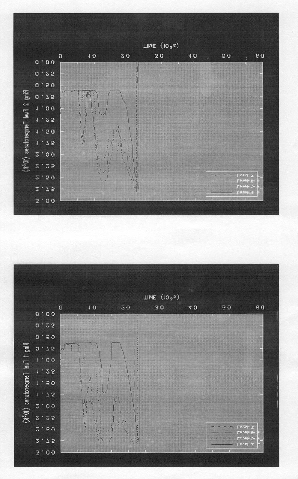
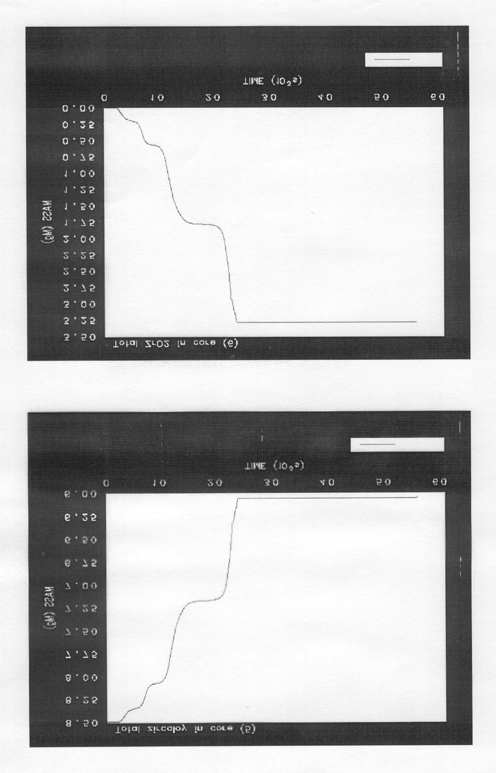
18 RESULTS OF THE STABILIZATION FOR s OF THE ACCIDENT TIME 741
19 742
20 743
21 744
22 745
23 746
24 747
25 748
26 749
27 750
28 751
29 752
1: CANDU Reactor. B. Rouben McMaster University Nuclear Reactor Physics EP 4D03/6D Sept-Dec September 1
 1: CANDU Reactor B. Rouben McMaster University Nuclear Reactor Physics EP 4D03/6D03 2015 Sept-Dec 2015 September 1 Outline A quick look at the design of CANDU Reactors: Reactor Assembly Pressure Tubes
FUNDAMENTAL SAFETY OVERVIEW VOLUME 2: DESIGN AND SAFETY CHAPTER E: THE REACTOR COOLANT SYSTEM AND RELATED SYSTEMS
 PAGE : 1 / 13 4. PRESSURISER 4.1. DESCRIPTION The pressuriser (PZR) is a pressurised vessel forming part of the reactor coolant pressure boundary (CPP) [RCPB]. It comprises a vertical cylindrical shell,
Module 03 Pressurized Water Reactors (PWR) Generation 3+
 Generation 3+") Module 03 Pressurized Water Reactors (PWR) Generation 3+ 1.3.2017 Prof.Dr. Böck Technical University Vienna Atominstitut Stadionallee 2, 1020 Vienna, Austria ph: ++43-1-58801 141368 boeck@ati.ac.at Flow
Module 03 Pressurized Water Reactors (PWR) Generation 3+ 1.3.2017 Prof.Dr. Böck Technical University Vienna Atominstitut Stadionallee 2, 1020 Vienna, Austria ph: ++43-1-58801 141368 boeck@ati.ac.at Flow
AP1000 European 5. Reactor Coolant System and Connected Systems Design Control Document
 CHAPTER 5 REACTOR COOLANT SYSTEM AND CONNECTED SYSTEMS 5.1 Summary Description This section describes the reactor coolant system (RCS) and includes a schematic flow diagram of the reactor coolant system
ANALYSIS OF BREST-OD-300 SAFETY DURING ANTICIPATED OPERATIONAL OCCURRENCES
 ANALYSIS OF BREST-OD-300 SAFETY DURING ANTICIPATED OPERATIONAL OCCURRENCES D.V. Didorin, V.A. Kogut, A.G. Muratov, V.V. Tyukov, A.V. Moiseev (NIKIET, Moscow, Russia) 1. Brief description of the aim and
CONTROL SYSTEM DESIGN FOR A SMALL PRESSURIZED WATER REACTOR
 CONTROL SYSTEM DESIGN FOR A SMALL PRESSURIZED WATER REACTOR Peiwei Sun and Jianmin Zhang Xi'an Jiaotong University No. 28 Xianing Road West, Xi'an, Shaanxi 710049, China sunpeiwei@mail.xjtu.edu.cn; zhangjm@mail.xjtu.edu.cn
FUNDAMENTAL SAFETY OVERVIEW VOLUME 2: DESIGN AND SAFETY CHAPTER D: REACTOR AND CORE
 PAGE : 1 / 12 SUB-CHAPTER D.2 FUEL DESIGN This sub-chapter lists the safety requirements related to the fuel assembly design. The main characteristics of the fuel and control rod assemblies which have
Rosatom Seminar on Russian Nuclear Energy Technologies and Solutions
 ROSATOM STATE ATOMIC ENERGY CORPORATION ROSATOM VVER-100 Reactor Plant and Safety Systems Rosatom Seminar on Russian Nuclear Energy Technologies and Solutions N.S. Fil Chief Specialist, OKB GIDROPRESS
Module 09 Heavy Water Moderated and Cooled Reactors (CANDU)
") Prof.Dr. Böck Technical University Vienna Atominstitut Stadionallee 2, 1020 Vienna, Austria ph: ++43-1-58801 141368 boeck@ati.ac.at Module 09 Heavy Water Moderated and Cooled Reactors (CANDU) 1.10.2016
Prof.Dr. Böck Technical University Vienna Atominstitut Stadionallee 2, 1020 Vienna, Austria ph: ++43-1-58801 141368 boeck@ati.ac.at Module 09 Heavy Water Moderated and Cooled Reactors (CANDU) 1.10.2016
SUB-CHAPTER B.3 COMPARISON TABLE COMPARISON WITH REACTORS OF SIMILAR DESIGN (N4 AND KONVOI)
") CHAPTER B: INTRODUCTION AND GENERAL DESCRIPTION OF THE SUB-CHAPTER: B.3 SECTION : - PAGE : 1 / 9 SUB-CHAPTER B.3 COMPARISON TABLE COMPARISON WITH REACTORS OF SIMILAR DESIGN (N4 AND KONVOI) A comparison
CHAPTER B: INTRODUCTION AND GENERAL DESCRIPTION OF THE SUB-CHAPTER: B.3 SECTION : - PAGE : 1 / 9 SUB-CHAPTER B.3 COMPARISON TABLE COMPARISON WITH REACTORS OF SIMILAR DESIGN (N4 AND KONVOI) A comparison
Module 03 Pressurized Water Reactors (PWR) Generation 3+
 Generation 3+") Module 03 Pressurized Water Reactors (PWR) Generation 3+ Status 1.10.2013 Prof.Dr. Böck Vienna University of Technology Atominstitute Stadionallee 2 A-1020 Vienna, Austria ph: ++43-1-58801 141368 boeck@ati.ac.at
Module 03 Pressurized Water Reactors (PWR) Generation 3+ Status 1.10.2013 Prof.Dr. Böck Vienna University of Technology Atominstitute Stadionallee 2 A-1020 Vienna, Austria ph: ++43-1-58801 141368 boeck@ati.ac.at
CANDU Fuel Bundle Deformation Model
 CANDU Fuel Bundle Deformation Model L.C. Walters A.F. Williams Atomic Energy of Canada Limited Abstract The CANDU (CANada Deuterium Uranium) nuclear power plant is of the pressure tube type that utilizes
CAREM PROTOTYPE CONSTRUCTION AND LICENSING STATUS
 CAREM PROTOTYPE CONSTRUCTION AND LICENSING STATUS H. Boado Magan a, D. F. Delmastro b, M. Markiewicz b, E. Lopasso b, F. Diez, M. Giménez b, A. Rauschert b, S. Halpert a, M. Chocrón c, J.C. Dezzutti c,
POWER RAMPING AND CYCLING TESTING OF VVER FUEL RODS IN THE MIR REACTOR
 POWER RAMPING AND CYCLING TESTING OF VVER FUEL RODS IN THE MIR REACTOR A.G. Eshcherkin*, V.A. Ovchinnikov, E.E. Shakhmut, E.E. Kuznetsova, A.L. Izhutov, V.V. Kalygin INTRODUCTION A series of experiments
SUB-CHAPTER E.4 DESIGN OF COMPONENTS AND SUB-SYSTEMS
 PAGE : 1 / 11 SUB-CHAPTER E.4 DESIGN OF COMPONENTS AND SUB-SYSTEMS 1. REACTOR COOLANT PUMPS 1.1. DESCRIPTION OF REACTOR COOLANT PUMPS The reactor coolant pumps (GMPP) [RCP] are assigned at RCC-M level
Status of HPLWR Development
 Status of HPLWR Development Thomas Schulenberg SCWR System Steering Committee Karlsruhe Institute of Technology Germany What is a Supercritical Water Cooled Reactor? PH HP IP LP PH Produces superheated
Startup and Operation of SEE-THRU Nuclear Power Plant for Student Performance MP-SEE-THRU-01 Rev. 018
 Student Operating Procedure Millstone Station Startup and Operation of SEE-THRU Nuclear Power Plant for Student Performance Approval Date: 01/12/2011 Effective Date: 01/12/2011 TABLE OF CONTENTS 1. PURPOSE...3
AP1000 European 7. Instrumentation and Controls Design Control Document
 7.3 Engineered Safety Features AP1000 provides instrumentation and controls to sense accident situations and initiate engineered safety features (ESF). The occurrence of a limiting fault, such as a loss
Re evaluation of Maximum Fuel Temperature
 IAEA Technical Meeting on on Re evaluation of Maximum Operating Temperatures and Accident Conditions for High Temperature Reactor Fuel and Structural Materials, 10 12 July 2012, Vienna, Austria Re evaluation
1. INTRODUCTION XA SLIGHTLY ENRICHED URANIUM FUEL FOR A PHWR
 SLIGHTLY ENRICHED URANIUM FUEL FOR A PHWR XA9846610 C. NOTARI, A. MARAJOFSKY Centra Atomico Constituyentes, Comision Nacional de Energia Atomica, Buenos Aires, Argentina Abstract An improved fuel element
Single-phase Coolant Flow and Heat Transfer
 22.06 ENGINEERING OF NUCLEAR SYSTEMS - Fall 2010 Problem Set 5 Single-phase Coolant Flow and Heat Transfer 1) Hydraulic Analysis of the Emergency Core Spray System in a BWR The emergency spray system of
By: Eugenijus Uspuras Algirdas Kaliatka Sigitas Rimkevicius ASME 2012 Verification & Validation Symposium May 2-4, 2012, Las Vegas, NV
 Computer codes validation for transient analysis at nuclear power plants with RBMK-1500 reactor By: Eugenijus Uspuras Algirdas Kaliatka Sigitas Rimkevicius ASME 2012 Verification & Validation Symposium
EXTENDED STUDY OF COOLABILITY OF VVER BUNDLE WITH BALLOONED REGION
 EXTENDED STUDY OF COOLABILITY OF VVER BUNDLE WITH BALLOONED REGION Imre Nagy, Zoltán Hózer, Tamás Novotny, Péter Windberg, András Vimi Centre for Energy Research, Hungarian Academy of Sciences H-1525 Budapest,
IMPROVED BWR CORE DESIGN USING HYDRIDE FUEL
 Joint Reactor Seminar University of Tokyo (GoNERI) and UC Berkeley March 5, 2009 IMPROVED BWR CORE DESIGN USING HYDRIDE FUEL Massimiliano Fratoni, Alessandro Piazza, Ehud Greenspan University of California,
The Establishment and Application of TRACE/FRAPTRAN Model for Kuosheng Nuclear Power Plant
 The Establishment and Application of /FRAPTRAN Model for Kuosheng Nuclear Power Plant S. W. Chen, W. K. Lin, J. R. Wang, C. Shih, H. T. Lin, H. C. Chang, W. Y. Li Abstract Kuosheng nuclear power plant
SPERT-III: REACTIVITY INSERTION ANALYSIS WITH SIMULATE-3K
 SPERT-III: REACTIVITY INSERTION ANALYSIS WITH SIMULATE-3K Gerardo Grandi 2012 International Users Group Meeting Charlotte, NC, USA May 2-3, 2012 2 Overview Introduction Special Power Excursion Reactor
INSPECTION TECHNIQUE FOR BWR CORE SPRAY THERMAL SLEEVE WELD
 More Info at Open Access Database www.ndt.net/?id=18479 INSPECTION TECHNIQUE FOR BWR CORE SPRAY THERMAL SLEEVE WELD ABSTRACT J.L. Fisher, G. Light, Jim Crane, Albert Parvin, Southwest Research Institute,
AP1000 Plant Overview
 AP1000 Plant Overview Westinghouse IEEE Subcommittee on Qualification Tom Hayes Passive Plant Projects hayestp@westinghouse.com 1-412-374-4420 Slide 1 Westinghouse Passive Plants Meet Power Company Needs
Key-Words : Eddy Current Testing, Garter Spring, Coolant Channels, Eddy Current Test Coil Design etc.
 More Info at Open Access Database www.ndt.net/?id=15054 Development of Eddy Current Test Technique for Detection of Garter Springs in 540 and 700 MWe Pressurized Heavy Water Reactors Arbind Kumar AFD,
CONSIDERATIONS FOR THE DEVELOPMENT OF A DEVICE FOR THE DECOMMISSIONING OF THE FUEL CHANNELS IN THE CANDU NUCLEAR REACTOR
 CONSIDERATIONS FOR THE DEVELOPMENT OF A DEVICE FOR THE DECOMMISSIONING OF THE FUEL CHANNELS IN THE CANDU NUCLEAR REACTOR FIZ. DRD. Gabi ROSCA FARTAT e-mail: rosca_gabi@yahoo.com PROF. UNIV. EMERIT DR.
CHALLENGES IN DESIGNING SYNTHESIS CONVERTERS FOR VERY LARGE METHANOL PRODUCTION CAPACITY
 CHALLENGES IN DESIGNING SYNTHESIS CONVERTERS FOR VERY LARGE METHANOL PRODUCTION CAPACITY By E. Filippi METHANOL CASALE S.A., Lugano, Switzerland presented at the 5th Iran Petrochemical Forum Tehran, Iran
Super-Critical Water-cooled Reactors
 Super-Critical Water-cooled Reactors (SCWRs) SCWR System Steering Committee T. Schulenberg, H. Matsui, L. Leung, A. Sedov Presented by C. Koehly GIF Symposium, San Diego, Nov. 14-15, 2012 General Features
GENERATOR SEAL OIL SYSTEM
 GENERATOR SEAL OIL SYSTEM Eskom power utility utilized Flownex SE simulation capabilities to mitigate system shutdowns caused by generator hydrogen (H 2 ) seal ring failures. Engineers modelled the hydrogen
CNS Fuel Technology Course: Fuel Design Requirements
 4525 Lakeshore Road Burlington, Ontario L7L 1B3 Phone: 905-639-4090 FAX: 905-639-9506 CNS Fuel Technology Course: Fuel Design Requirements Al Manzer, B.Sc., M. Eng. Senior Fuel Specialist CANTECH Associates
The B&W mpower TM Small Modular Reactor I&C Design, Architecture and Challenges
 The B&W mpower TM Small Modular Reactor I&C Design, Architecture and Challenges IAEA Technical Meeting May 23, 2013 B.K. Arnholt 2013 Generation mpower LLC All rights reserved. Agenda Introduction to the
Visual Inspection of Reactor Vessel Head Penetration Nozzles
 International Conference Nuclear Energy for New Europe 2003 Portorož, Slovenia, September 8-11, 2003 http://www.drustvo-js.si/port2003 Visual Inspection of Reactor Vessel Head Penetration Nozzles Simon
A.L. Izhutov, A.V. Burukin, Current and prospective fuel test programmes in the MIR reactor
 A.L. Izhutov, A.V. Burukin, S.A. Iljenko,, V.A. Ovchinnikov, V.N. Shulimov,, V.P. Smirnov State Scientific Centre of Russia Research Institute of Atomic Reactors, 433510, Dimitrovgrad, Ulyanovsk region,
The further development of WWER-440 fuel design performance. Authors: V.B.Lushin, I.N.Vasilchenko, J.A.Ananjev, G.V.Abashina OKB "GIDROPRESS".
 The further development of WWER-440 fuel design performance Authors: V.B.Lushin, I.N.Vasilchenko, J.A.Ananjev, G.V.Abashina OKB "GIDROPRESS". 1 Introduction VVER fuel development is determined by two main
Global VPI Insulated Indirectly Hydrogen-Cooled Turbine Generator for Single-Shaft Type Combined Cycle Power Generation Facilities
 Global VPI Insulated Indirectly Hydrogen-Cooled Turbine Generator for Single-Shaft Type Combined Cycle Power Generation Facilities YAMAZAKI Masaru NIIKURA Hitoshi TANIFUJI Satoshi ABSTRACT Fuji Electric
Test Facilities in Germany. Dr. Gerd Brinkmann / Dieter Vanvor BriVaTech Consulting Wien,
 Test Facilities in Germany Dr. Gerd Brinkmann / Dieter Vanvor BriVaTech Consulting Wien, 10.06. 13.06.2014 BriVaTech Consulting, Hemhofen, GERMANY ALL RIGHTS RESERVED Page 1 Date 12-15.01.2015 Test Facilities
CONSIDERATIONS REGARDING THE HORIZONTAL FUEL CHANNELS IN THE CANDU 6 NUCLEAR REACTOR. PART 1 - PRESENTATION OF THE FUEL CHANNEL
 6 th International Conference Computational Mechanics and Virtual Engineering COMEC 2015 15-16 October 2015, Braşov, Romania CONSIDERATIONS REGARDING THE HORIZONTAL FUEL CHANNELS IN THE CANDU 6 NUCLEAR
SMR multi-physics calculations with Serpent at VTT
 VTT TECHNICAL RESEARCH CENTRE OF FINLAND LTD SMR multi-physics calculations with Serpent at VTT Serpent UGM 2016 Riku Tuominen, VTT Outline Serpent-COSY coupling Future work 18/10/2016 2 COSY Three-dimensional
AP Plant Operational Transient Analysis
 www.ijnese.org International Journal of Nuclear Energy Science and Engineering Volume 3 Issue 2, June 2013 AP1000 1 Plant Operational Transient Analysis LIU Lixin 1, ZHENG Limin 2 Shanghai Nuclear Engineering
S. Y. Park (*), K. I. Ahn
, K. I. Ahn") IEM on Strengthening R&D Effectiveness in the Light of the Accident at the Fukushima Daiichi NPP, Vienna, 16-0 Feb. 015 Assessment of the Mitigative Strategy using External Coolant Injection for OPR-1000
IEM on Strengthening R&D Effectiveness in the Light of the Accident at the Fukushima Daiichi NPP, Vienna, 16-0 Feb. 015 Assessment of the Mitigative Strategy using External Coolant Injection for OPR-1000
REDACTED PUBLIC VERSION HPC PCSR3 Sub-chapter 4.2 Fuel Design NNB GENERATION COMPANY (HPC) LTD REDACTED PUBLIC VERSION HPC PCSR3: { PI Removed }
 LTD REDACTED PUBLIC VERSION HPC PCSR3: { PI Removed }") Page No.: i / iii NNB GENERATION COMPANY (HPC) LTD HPC PCSR3: CHAPTER 4 REACTOR AND CORE DESIGN SUB-CHAPTER 4.2 FUEL DESIGN { PI Removed } uncontrolled. 2017 Published in the United Kingdom by NNB Generation
Page No.: i / iii NNB GENERATION COMPANY (HPC) LTD HPC PCSR3: CHAPTER 4 REACTOR AND CORE DESIGN SUB-CHAPTER 4.2 FUEL DESIGN { PI Removed } uncontrolled. 2017 Published in the United Kingdom by NNB Generation
Journal of Engineering Sciences and Innovation Volume 2, Issue 4 / 2017, pp
 Journal of Engineering Sciences and Innovation Volume 2, Issue 4 / 2017, pp. 11-19 Technical Sciences Academy of Romania www.jesi.astr.ro A. Mechanics, Mechanical and Industrial Engineering, Mechatronics
Neutronics of Prismatic Fluoride Salt Cooled High Temperature Reactors
 Neutronics of Prismatic Fluoride Salt Cooled High Temperature Reactors Workshop on Advanced Reactors Concepts PHYSOR 2012 Knoxville, TN April 15, 2012 Dan Ilas IlasD@ornl.gov Main Neutronic Design Characteristics
Report No. IDO APPENDIX B ML-1 PLANT CHARACTERISTICS 1. GENERAL Mu to gas; 3.41 Mw total Cycle efficiency. Gross elect. wr. Net elect.
 ... Report No. IDO-28653 APPENDIX B ML-1 PLANT CHARACTERISTICS 0 Design performance at 100 F Gross electrical output Net electrical output 1. GENERAL Reactor thermal power 2.98 Mu to gas; 3.41 Mw total
*TATSUYA KUNISHI, HITOSHI MUTA, KEN MURAMATSU AND YUKI KAMEKO TOKYO CITY UNIVERSITY GRADUATE SCHOOL
 Methodology of Treatment of Multiple Failure Initiating Events for Seismic PRA (2)Success Criteria Analysis for Multiple Pipe Break Accidents of a PWR *TATSUYA KUNISHI, HITOSHI MUTA, KEN MURAMATSU AND
B. HOLMQVIST Nuclear Fuel Division, ABB Atom AB, Vasteras, Sweden
 I Iflllll IPIBM1I IHtl!!!! Blini Vllll! «! all REDUCTION OF COST OF POOR QUALITY IN NUCLEAR FUEL MANUFACTURING XA0055764 B. HOLMQVIST Nuclear Fuel Division, ABB Atom AB, Vasteras, Sweden Abstract Within
ACCIDENT TOLERANT FUEL AND RESULTING FUEL EFFICIENCY IMPROVEMENTS
 Advances in Nuclear Fuel Management V (ANFM 2015) Hilton Head Island, South Carolina, USA, March 29 April 1, 2015, on CD-ROM, American Nuclear Society, LaGrange Park, IL (2015) ACCIDENT TOLERANT FUEL AND
SUBMARINE NOZZLE PIPE MANIPULATOR. R. Zeilinger, G. Hünies, F. Mohr AREVA NDE-Solutions/ intelligendt Systems & Services GmbH
 SUBMARINE NOZZLE PIPE MANIPULATOR R. Zeilinger, G. Hünies, F. Mohr AREVA NDE-Solutions/ intelligendt Systems & Services GmbH ABSTRACT: AREVA NDE-Solutions German division - intelligendt Systems & Services
ALCOHOL LOX STEAM GENERATOR TEST EXPERIENCE
 ALCOHOL LOX STEAM GENERATOR TEST EXPERIENCE Klaus Schäfer, Michael Dommers DLR, German Aerospace Center, Institute of Space Propulsion D 74239 Hardthausen / Lampoldshausen, Germany Klaus.Schaefer@dlr.de
An Investigation on the Fuel Assembly Structural Performance for the PLUS7 TM Fuel Design
 2th International Conference on Structural Mechanics in Reactor Technology (SMiRT 2) Espoo, Finland, August 9-14, 29 SMiRT 2-Division 6, Paper 1824 An Investigation on the Fuel Assembly Structural Performance
BEYOND DESIGN BASIS ACCIDENT CALCULATION OF ALLEGRO GASCOOLED FAST REACTOR
 BEYOND DESIGN BASIS ACCIDENT CALCULATION OF ALLEGRO GASCOOLED FAST REACTOR Dr. Gábor L. Horváth horvathlg@nubiki.hu MELCOR European Users Group ZAGREB 25 27 April 2018 Contents Background of calculations
DEVELOPMENT OF A 3D MODEL OF TUBE BUNDLE OF VVER REACTOR STEAM GENERATOR
 DEVELOPMENT OF A 3D MODEL OF TUBE BUNDLE OF VVER REACTOR STEAM GENERATOR V.F. Strizhov, M.A. Bykov, A.Ye. Kiselev A.V. Shishov, A.A. Krutikov, D.A. Posysaev, D.A. Mustafina IBRAE RAN, Moscow, Russia Abstract
Fuel cladding stress evaluation for the control rods pattern change at the Shimane Nuclear Power Station Unit No1 and No2
 GENES4/ANP2003, Sep. 15-19, 2003, Kyoto, JAPAN Paper 1086 Fuel cladding stress evaluation for the control rods pattern change at the Shimane Nuclear Power Station Unit No1 and No2 Saemi Shimatani 1*, Masayuki
Super-Critical Water-cooled Reactor
 Super-Critical Water-cooled Reactor SCWR System Steering Committee Y.P. Huang (Chair, China) L. Leung (Co-Chair, Canada, Presenter) R. Novotny (EU, awaiting confirmation) A. Sedov (Russian Federation)
April 23, U.S. Nuclear Regulatory Commission ATTN: Document Control Desk Washington, DC
 Cwnsunme, EIneIUY A CMS Energy Compan}y Daniel J. Malone foireotor, Ffgineeung April 23, 2001 U.S. Nuclear Regulatory Commission ATTN: Document Control Desk Washington, DC 20555-0001 DOCKET 50-255 - LICENSE
ABWR Design and Its Evolution - Primary System Design of ABWR and ABWR-II -
 GENES4/ANP2003, Sep. 15-19, 2003, Kyoto, JAPAN Paper 1161 ABWR Design and Its Evolution - Primary System Design of ABWR and ABWR-II - Katsumi Yamada 1*, Satoko Tajima 1, Masaaki Tsubaki 2 and Hideo Soneda
FIG Top view of the reactor core of the ARE. Hexagonal beryllium oxide blocks serve as the moderator. Inconel tubes pass through the moderator
 CHAPTER 16 AIRCRAFT REACTOR EXPERIMENT* The feasibility of the operation of a molten-salt-fueled reactor at a truly high temperature was demonstrated in 1954 in experiments with a reactor constructed at
TRACE INPUT MODEL FOR SPES3 FACILITY
 CIRTEN CONSORZIO INTERUNIVERSITARIO PER LA RICERCA TECNOLOGICA NUCLEARE UNIVERSITA DI PALERMO DIPARTIMENTO DI INGEGNERIA NUCLEARE TRACE INPUT MODEL FOR SPES3 FACILITY F. Castiglia, P. Chiovaro, M. Ciofalo,
Accident-related fuel experiments in Halden --- HRP LOCA Test Series IFA-650
 Accident-related fuel experiments in Halden --- HRP LOCA Test Series IFA-650 TWGFPT Orientation 24 April 2014 W. Wiesenack 1 LOCA test overview Issues to be addressed with the HRP LOCA tests Fuel fragmentation,
FBR and ATR fuel developments in JNC
 International Seminar on MOX Utilization February 19, 2002 FBR and ATR fuel developments in JNC Design and performance of MOX fuel in safety view points Plutonium Fuel Center, Tokai Works, Japan Nuclear
The ADS-IDAC Dynamic PSA Platform with Dynamically Linked System Fault Trees
 The ADS-IDAC Dynamic PSA Platform with Dynamically Linked System Fault Trees Mihai Diaconeasa Center for Reliability and Resilience Engineering The B. John Garrick Institute for the Risk Sciences University
The role of CVR in the fuel inspection at Temelín NPP
 The role of CVR in the fuel inspection at Temelín NPP Marek Mikloš, Martina Malá Research Centre Řež, Ltd. Daniel Ernst NPP Temelín IAEA TM on Hot Cell Post-Irradiation Examination and Pool-Side Inspection
THERMAL TO MECHANICAL ENERGY CONVERSION: ENGINES AND REQUIREMENTS Vol. I - Thermal Protection of Power Plants - B.M.Galitseyskiy
 THERMAL PROTECTION OF POWER PLANTS B.M.Galitseyskiy Department of Aviation Space Thermotechnics, Moscow Aviation Institute, Russia Keywords: Heat transfer, thermal protection, porous cooling, block cooling,
Investigation of a CoolantMixing Phenomena within the Reactor Pressure Vessel of a VVER-1000 Reactor with Different Simulation Tools
 nvestigation of a CoolantMixing Phenomena within the Reactor Pressure Vessel of a VVER-1000 Reactor with Different Simulation Tools The MT Faculty has made this article openly available. Please share how
Effect of Compressor Inlet Temperature on Cycle Performance for a Supercritical Carbon Dioxide Brayton Cycle
 The 6th International Supercritical CO2 Power Cycles Symposium March 27-29, 2018, Pittsburgh, Pennsylvania Effect of Compressor Inlet Temperature on Cycle Performance for a Supercritical Carbon Dioxide
Thermal Hydraulics Design Limits Class Note II. Professor Neil E. Todreas
 Thermal Hydraulics Design Limits Class Note II Professor Neil E. Todreas The following discussion of steady state and transient design limits is extracted from the theses of Carter Shuffler and Jarrod
Fission gas release and temperature data from instrumented high burnup LWR fuel
 Fission gas release and temperature data from instrumented high burnup LWR fuel XA0202217 T. Tverberg, W. Wiesenack Institutt for Energiteknikk, OECD Halden Reactor Project, Norway Abstract.The in-pile
Investigation of converging slot-hole geometry for film cooling of gas turbine blades
 Project Report 2010 MVK160 Heat and Mass Transport May 12, 2010, Lund, Sweden Investigation of converging slot-hole geometry for film cooling of gas turbine blades Tobias Pihlstrand Dept. of Energy Sciences,
Oconee Nuclear Station ALLOY 600 REPAIRS 1EOC23
 Oconee Nuclear Station ALLOY 600 REPAIRS 1EOC23 We re requiring more inspections due to susceptibility of material to cracking Some utilities have implemented mitigative actions Stress improvement Weld
EXAMINATION OF NOZZLE INNER RADIUS AND PIPING FROM THE OUTER SURFACE
 More Info at Open Access Database www.ndt.net/?id=18560 ABSTRACT NEW DEVELOPMENTS FOR AUTOMATED NOZZLE INNER RADIUS AND PIPING INSPECTIONS D. Eargle,WesDyne International, USA WesDyne has recently engaged
Check Valve Solutions for Nuclear Applications. NozzleCheck Valves
 Check Valve Solutions for Nuclear Applications NozzleCheck Valves Over 40 Years of Nuclear Experience Enertech, a business unit of Curtiss-Wright Flow Control Company, has been committed to the nuclear
THE ROMANIAN IRRADIATION TESTS PREPARED FOR IAEA/OECD DATABASE Author: M. C. Paraschiv, Institute for Nuclear Research Pitesti, Romania
 THE ROMANIAN IRRADIATION TESTS PREPARED FOR IAEA/OECD DATABASE Author: M. C. Paraschiv, Institute for Nuclear Research Pitesti, Romania Abstract The main features of two Romanian experimental fuel elements
SIMPLIFIED METHOD OF WATER COOLED EXHAUST SYSTEM DESIGN AND PERFORMANCE ASSESSMENT
 SIMPLIFIED METHOD OF WATER COOLED EXHAUST SYSTEM DESIGN AND PERFORMANCE ASSESSMENT Czesław Dymarski Gdańsk University of Technology Faculty of Ocean Engineering and Ship Technology Narutowicza 11/12 str.,
Engineering Diploma Resource Guide ST280 ETP Hydraulics (Engineering)
") Engineering Diploma Resource Guide ST80 ETP Hydraulics (Engineering) Introduction Hydraulic systems are a fundamental aspect of engineering. Utilised across a variety of sectors including aviation, construction,
Engineering Diploma Resource Guide ST80 ETP Hydraulics (Engineering) Introduction Hydraulic systems are a fundamental aspect of engineering. Utilised across a variety of sectors including aviation, construction,
PV Newsletter Monthly Publication from CoDesign Engineering Skills Academy
 April 15, 2013 PV Newsletter Monthly Publication from CoDesign Engineering Skills Academy www.codesignengg.com This article has some reproductions from the PV Newsletter - Volume 1, Issue 10 contributed
Introduction and Summary
 6 Chapter Core and Fuel Design Introduction and Summary The design of the Advanced Boiling Water Reactor (ABWR) core and fuel is based on the proper combination of many design variables and operating experience.
EXPERIMENTAL RESEARCH AND OPTIMIZATION OF BREST-OD-300 MCP MODEL PERFORMANCE IN A LEAD COOLANT
 EXPERIMENTAL RESEARCH AND OPTIMIZATION OF BREST-OD-300 MCP MODEL PERFORMANCE IN A LEAD COOLANT A.V. Beznosov, P.A. Bokov, O.I. Buzina, A.D. Zudin, A.V. Lvov, T.M. Semayeva, N.D. Trushkov (NNSTU n.a. R.E.
CARA design criteria for HWR fuel burnup extension
 CARA design criteria for HWR fuel burnup extension P.C. Florido, R.O. Cirimello, J.E. Bergallo, A.C. Marino, D.F. Delmastro, D.O. Brasnarof, J.H. Gonzalez, L.A. Juanico Centro Atomico Bariloche, Comision
Presented at SC-2, Meeting October 5-6, 2010,, Seattle, WA
 U.S. EPR EQ Program Update Nissen M. Burstein Technical Consultant Presented at SC-2, Meeting 10-02 October 5-6, 2010,, Seattle, WA EPR is a trademark of the AREVA Group. Overview of U.S. EPR Reactor Redundant
NATIONAL NUCLEAR SECURITY ADMINISTRATION GLOBAL THREAT REDUCTION INITIATIVE Core Modifications to address technical challenges of conversion
 NATIONAL NUCLEAR SECURITY ADMINISTRATION GLOBAL THREAT REDUCTION INITIATIVE Core Modifications to address technical challenges of conversion G17 G18 G19 G20 G21 G16 F15 F16 G22 F17 F14 9.76 9.85 9.91 F18
PROF. UNIV. EMERIT DR. ING.
 CONSIDERATIONS FOR THE DEVELOPMENT OF A DEVICE FOR THE DECOMMISSIONING OF THE HORIZONTAL FUEL CHANNELS IN THE CANDU 6 NUCLEAR REACTOR PART 2 - FUEL CHANNEL PRESENTATION FIZ. DRD. Gabi ROSCA FARTAT e-mail:
AP1000 European 4. Reactor Design Control Document CHAPTER 4 REACTOR. 4.1 Summary Description
 CHAPTER 4 REACTOR 4.1 Summary Description This chapter describes the mechanical components of the reactor and reactor core, including the fuel rods and fuel assemblies, the nuclear design, and the thermal-hydraulic
HIGH PERFORMANCE SEALING
 12-2010 HIGH PERFORMANCE SEALING GASKETS FOR ENHANCED JOINT INTEGRITY Although relatively new to the U.S. market, the FLEXPRO gasket has been providing an extremely tight, reliable seal in a wide range
GT-Suite Users Conference
 GT-Suite Users Conference Thomas Steidten VKA RWTH Aachen Dr. Philip Adomeit, Bernd Kircher, Stefan Wedowski FEV Motorentechnik GmbH Frankfurt a. M., October 2005 1 Content 2 Introduction Criterion for
5.0 REACTOR COOLANT SYSTEM AND CONNECTED SYSTEMS
 Summary Description 5.0 REACTOR COOLANT SYSTEM AND CONNECTED SYSTEMS This chapter of the U.S. EPR Final Safety Analysis Report (FSAR) is incorporated by reference with supplements as identified in the
About Reasonably Achievable Balance between Economy and Safety indices in WWERs
 IAEA INPRO DF8, Vienna 26-29 August 2014 About Reasonably Achievable Balance between Economy and Safety indices in WWERs Grigory Ponomarenko OKB GIDROPRESS Podolsk, Russian Federation Contents 1. Safety
Technical Trend of Bearings for Automotive Drive Train
 SURVEY Technical Trend of Bearings for Automotive Drive Train M. KITAMURA Circumstances surrounding the automobile industry require improvement in fuel efficiency and reduction of CO 2 gas emission in
Recommendations for a demonstrator of Molten Salt Fast Reactor
 Recommendations for a demonstrator of Molten Salt Fast Reactor E. MERLE-LUCOTTE, D. HEUER, M. ALLIBERT, M. BROVCHENKO, V. GHETTA, P. RUBIOLO, A. LAUREAU merle@lpsc.in2p3.fr Professor at Grenoble INP/PHELMA
AVL SERIES BATTERY BENCHMARKING. Getting from low level parameter to target orientation
 1 AVL SERIES BATTERY BENCHMARKING Getting from low level parameter to target orientation CONTENTS OVERVIEW 1. AVL Introduction 2. Focus Series Battery Benchmarking 3. Benchmarking process 4. Target comparability
Influence of Decontamination
 Influence of Decontamination Michael Knaack 18th February 2016 Influence of Decontamination ~ February 2016 ~ 1 Decontamination Overview of reasons for decontamination Different methods Advantages / Disadvantages
RULES FOR THE CONSTRUCTION AND CLASSIFICATION OF SHIPS IDENTIFIED BY THEIR MISSIONS CHAPTERS APPROACH
 PART II RULES FOR THE CONSTRUCTION AND CLASSIFICATION OF SHIPS IDENTIFIED BY THEIR MISSIONS TITLE 47 SUPPLY VESSELS SECTION 6 PIPING CHAPTERS A B C D E F G H T APPROACH MATERIALS AND MANUFACTURE - See
ANALYSIS OF REVERSE FLOW IN LOW-RISE INVERTED U-TUBE STEAM GENERATOR OF PWR PACTEL FACILITY
 ANALYSIS OF REVERSE FLOW IN LOW-RISE INVERTED U-TUBE STEAM GENERATOR OF PWR PACTEL FACILITY Kauppinen, O-P., Riikonen, V., Kouhia, V., Hyvärinen, J. LUT School of Energy Systems / Nuclear Engineering Lappeenranta
Excitation system is of Static Silicon Excitation System, including excitation transformer, thyristors, and AVR.
 Turbo - Generator Type: QF Series 1. General The generator is a two pole, cylindrical rotor type synchronous machine, directly coupled with steam turbine. It has a closed-circuit cooling system to cool
Profile SFR-77 METL USA. LOCATION (address): Bldg. 308 / 9700 South Cass Avenue / Lemont, IL / USA
: Bldg. 308 / 9700 South Cass Avenue / Lemont, IL / USA") Profile SFR-77 METL USA GENERAL INFORMATION NAME OF THE Mechanisms Engineering Test Loop FACILITY ACRONYM METL ( pronounced Metal ) COOLANT(S) OF THE Sodium FACILITY LOCATION (address): Bldg. 308 / 9700
Profile SFR-77 METL USA GENERAL INFORMATION NAME OF THE Mechanisms Engineering Test Loop FACILITY ACRONYM METL ( pronounced Metal ) COOLANT(S) OF THE Sodium FACILITY LOCATION (address): Bldg. 308 / 9700
Numerical simulation of detonation inception in Hydrogen / air mixtures
 Numerical simulation of detonation inception in Hydrogen / air mixtures Ionut PORUMBEL COMOTI Non CO2 Technology Workshop, Berlin, Germany, 08.03.2017 09.03.2017 Introduction Objective: Development of
Heat Transfer Modeling using ANSYS FLUENT
 Lecture 7 Heat Exchangers 14.5 Release Heat Transfer Modeling using ANSYS FLUENT 2013 ANSYS, Inc. March 28, 2013 1 Release 14.5 Outline Introduction Simulation of Heat Exchangers Heat Exchanger Models