Product Manual. MARATHON EN395-6h 2009
|
|
|
- Ami Butler
- 6 years ago
- Views:
Transcription
1 Product Manual MARATHON EN395-6h 29
2 One partner all over the world Hägglunds Drives is one of the worlds leading manufacturer of heavy duty hydraulic drive systems. If what you need is low speed and high torque, then Hägglunds Drives should be your partner. If what you need is a durable drive system that will work under the toughest conditions with a minimum Worldwide distribution and service organization of maintenance, then Hägglunds Drives should be your partner. We develop, manufacture & market complete drive-systems and components of the highest quality, based upon our unique radial piston motors. Our industrial and marine customers are to be found all over the world. They know that when they need solutions, support or service, they have in us a partner they can trust. Hägglunds Drives main office and manufacturing plant is situated in Mellansel, Sweden. In Addition Hägglunds Drives is represented in 4 countries worldwide. Original EN395-5h, 22 The content in this manual is subject to change without notice or obligation, unless certified referring to a certain purchase order. Information contained herein should be confirmed before placing orders. 2
 to its maximum speed.")
3 Features High torques The Marathon motor is a high-torque motor which is mounted directly on the shaft or a driven machine without intermediate gears. Low speeds The Marathon motor is a low-speed motor and can run for practically an unlimited time from zero (stalling) to its maximum speed. High efficiency The mechanical efficiency of the Marathon motor is 97% within the motors optimal working range. Both driving and braking The Marathon motor can drive and brake in both directions, this is known as a four-quadrant drive. When the motor is braking it acts as a pump. Variable speed control The speed and direction of rotation of a Marathon motor are easily controlled by varying the flow. Response is fast due to the extremely low moment of inertia. Also limitation of the output torque can easily be achieved by controlling the pressure level. Reduces shock loads The moment of inertia of the Marathon motor is very low compared to electro-mechanical drives. Thus, the shock loads on the driven machine are significantly reduced. Severe environments The design of the Marathon motor makes it highly resistant to severe working environments. The moving parts of the motor are completely enclosed in hydraulic fluid, which has good lubrication quality. Thousands of Marathon motors are installed in explosive and chemically corrosive industrial environments, in extreme heat, or freezing cold throughout the world. Quick selection diagram for Marathon motors The curves below represent the torque and speed, corresponding to a basic rating life L 1h = 4 hours. Oil viscosity in the motor case 4 cst (187 SSU). Average operating torque Average speed rpm For operation in- or outside line screened area and for final selection, please contact your Hägglunds representative. 3

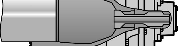
4 Functional description Hägglunds Drives hydraulic industrial motor MARATHON is of the radial-piston type with a rotating cylinder block/hollow shaft and a stationary case. The cylinder block is mounted in fixed roller bearings in the case. An even number of pistons are radially located in bores inside the cylinder block, and the valve plate directs the incoming and outgoing oil to and from the working pistons. Each piston is working against a cam 1 roller. When the hydraulic pressure is acting on the pistons, the cam rollers are pushed against the slope 2 on the cam ring that is rigidly connected to the case, thereby producing a torque. The reaction force is 3 transferred by the guide roller bearings on the cam rollers shaft ends to the two guide plates which are 5 connected to the cylinder block/hollow shaft. Rotation therefore occurs, and the torque available is proportional to the pressure in the system. Oil main lines are connected to ports R and L in the connection block and drain lines to ports D 1, D 2, D 3 or D 4 * in the port end housing. The motor is connected to the shaft of the driven machine through the hollow shaft of the cylinder block.the torque is transmitted by using a mechanical shaft coupling, or alternatively by splines. Fig. 1 Marathon motor 1 11 (D 4 *) 2 3 Quality To assure our quality we maintain a Quality Assurance System, certified to standard ISO 91, EN 291 and BS 575; Part 1. D 1 Valid patents US , SE , EP 12915, JP , GB , EU a 8 R, L 1. Cam ring 2. Cam roller 3. Piston 4. Shaft coupling 5. Cylinder block / hollow shaft 6. Guide plates 7. Guide roller bearing 7a. Cylinder block bearing 8. Connection block 9. Valve plate 1. Shaft end housing 11. Port end housing R = inlet or outlet port»r«l = inlet or outlet port»l«d 1, D 2, D 3 and D 4 * = drain ports 9 6 D 2 D 3 *D 4 = MB MB 4 4
 (bar) n Vi n Vi q = + q l (l/min) q = + ql 1 231 q - ql n= 1 (rpm) n= V i m q ( p- pc) P= (kw) q ( p- pc) in P= 6 in 1714 T n P= (hp) on driven shaft 5252 Ts ( p - p l -")
5 Calculation fundamentals Output power Output torque* ( = 98%) m Pressure required ( = 98%) m Flow rate required Output speed Inlet power P = T n 9549 T= T ( p - p - p ) p = T + pl + p T c (kw) on driven shaft s l c m S (Nm) (bar) n Vi n Vi q = + q l (l/min) q = + ql q - ql n= 1 (rpm) n= V i m q ( p- pc) P= (kw) q ( p- pc) in P= 6 in 1714 T n P= (hp) on driven shaft 5252 Ts ( p - p l - pc) T= m (lbf ft) 1 p = T 1 + p + p (psi) T l c s q-ql 231 V i m (gpm) (rpm) (hp) For more information See Powerful Engineering (EN347-4). Quantity Symbol Metric US Power P = kw hp Output torque T = Nm lbf ft Specific torque T s = Nm/bar lbf ft/1 psi Rotational speed n = rpm rpm Required pressure p = bar psi Data Metric Motor type S index Displacement Specific torque Quantity Symbol Metric US Pressure loss p l = bar psi Charge pressure p c = bar psi Flow rate required q = l/min gpm Total volumetric loss q l = l/min gpm Displacement V i = cm 3 /rev in 3 /rev Mechanical efficiency η m =,97 Rated speed* Max. speed Max pressure** Max. output power intermittent. MA MA MB MB ) MB MB 8-4 3) MB 8-4 1) MB ) MB MB ) MB ) MB MB 8-8 2) MB ) MB ) MB ) MB MB ) MB MB ) MB ) MB ) MB MB MB * Spec. considerations regarding charge pressure, cooling and choice of hydr. system for speeds above rated. ** The motors are designed according to DNV-rules. Test pressure 42 bar/6 psi. Peak/transient pressure 42 bar/6 psi maximum, allowed to occur 1 times. (1 High speed, Magnum port end and standard or lower displacement. (2 High speed, Magnum port end. (3 Lower displacement. V i T s n n p P 5
6 Data US Motor type S index Displacement Specific torque Rated speed* Max. speed Max. pressure** Max. output power intermittent. V i T S n n p P MA MA MB MB ) MB MB 8-4 3) MB 8-4 1) MB ) MB MB ) MB ) MB MB 8-8 2) MB ) MB ) MB ) MB MB ) MB MB ) MB ) MB ) MB MB MB * Spec. considerations regarding charge pressure, cooling and choice of hydr. system for speeds above rated. ** The motors are designed according to DNV-rules. Test pressure 42 bar/6 psi. Peak/transient pressure 42 bar/6 psi maximum, allowed to occur 1 times. (1 High speed, Magnum port end and standard or lower displacement. (2 High speed, Magnum port end. (3 Lower displacement. Definitions Rated speed x) Rated speed is the highest allowed speed for a charge pressure of 12 bar (175 psi) above case pressure. When a closed loop system is used, a minimum of 15% of oil is to be exchanged in the main loop. Special considerations are necessary regarding charge pressure, cooling and choice of hydraulic system for speeds above rated. x) Operating above rated conditions requires engineering approval. Max speed Maximum speed is the maximum allowed speed. Accepted conditions for standard type of motor: 1. Oil viscosity cst ( SSU). See page Temperature -35 C to +7 C (-31 F to +158 F). 3. Running case pressure -3 bar (-45 psi). Max case pressure 8 bar (116 psi) 4. Charge pressure (see diagram). 5. Volumetric losses (see diagram). 6
7 Ordering codes In order to identify Hägglunds Drives equipment exactly, the following ordering code is used. These ordering codes should be stated in full in all correspondence e.g. when ordering spare parts. Marathon motors Torque arm, TMA Double torque arm, DTMA 7
8 Ordering codes In order to identify Hägglunds Drives equipment exactly, the following ordering code is used. These ordering codes should be stated in full in all correspondence e.g. when ordering spare parts. Shock load manifold, VCMB Emergency stop manifold, VEMB Speed encoder, SPLL 85 A Mounting set for speed encoder Speed encoder, SPLL 85 D 8
9 Dimensions With hollow shaft, shrink disc coupling. Fig. 2 A Fig. 3 Drain Conn. (only this side) Rotating part I H F E MA 141 MA 2 MB 283 MB 4 MB 566 MB 8 C J dw Main Conn. Drain Conn. (both sides) Fig. 4 Fig. 5 A Drain Conn. (both sides) D Rot. part I G B H E MB 115 MB 16 MB 24 C J dw Main Conn. Drain Conn. (both sides) D B G Table 1 Dimensions for the motor Motor A B C D E F G H I J dw Weight kg (lb) Main conn. Drain conn. MA 141 MA 2 MA 283 MA (32,6) 9 (35,43) 958 (37,72) 144 (41,1) 738 (29,5) 754 (29,64) 795 (3,12) 783,5 (3,85) 46 (18,11) 53 (2,86) 146 (5,75) 145 (5,71) 165 (6,5) 171,5 (6,75) 159 (6,26) 172 (6,77) 522 (2,55) 558 (21,97) 583 (22,95) 626 (24,65) 452,5 (17,81) 467,5 (18,41) 492,5 (19,39) 55 (19,88) 288 (11,34) 33 (11,93) 299 (11,77) 32 (12,6) 84 (3,31) 16 (4,17) 111 (4,37) 322 (12,68) 342 (13,64) 397 (15,63) 432 (17,1) 14 (5,51) 155 (6,1) 18 (7,9) 2 (7,87) 99 (2183) 113 (249) 1395 (376) 1625 (3584) SAE 1 1/2 BSP 1 1/4 (D 1, D 2 ) BSP 1 (D 3 ) MB 566 MB (45,98) 1288 (5,71) 836,4 (32,93) 88 (34,65) 7 (27,56) 198 (7,79) 21 (7,91) 714 (28,7) 774 (3,43) 53,5 (19,82) 522 (2,55) 323 (12,72) 332 (13,7) 153 (6,2) 512 (2,16) 26 (1,24) 218 (4647) 285 (6184) MB 115 MB 16 MB (57,48) 125 (47,44) 1531 (6,28) 1288 (5,17) 567 (22,32) 619 (24,57) 238 (9,37) - 492,5 (19,39) 765,5 (3,14) 65 (23,82) 878 (34,57) 215 (8,46) 257 (1,12) 682 (26,85) 712 (28,3) 34 (13,38) 36 (14,17) SAE 2 46 (1141) BSP 1 1/4 (D 1-4 ) 646 (14222) 9
10 Dimensions With hollow shaft, shrink disc coupling. Fig. 6 Fig. 7 Rotating part A Drain Conn. (both sides) MB 32 MB 4 D E G F dw C Main Conn. Drain Conn. (both sides) B Table 2 Dimensions Motor A B C D E F G dw Weight kg (lb) Main conn. Drain conn. MB 32 MB (57,48) 1822 (71,74) 295 (82,48) 1288 (5,17) 651 (25,63) 586 (23,7) 859 (33,82) 95 (37,4) 238 (9,37) 46 (18,11) 893 (19682) 175 (23693) SAE 2 BSP 1 1/4 (D 1-4 ) With splines for flange mounting. Fig. 8 A Fig. 9 D H Drain Conn. (only this side) F E MA 141 MA 2 MB 283 MB 4 MB 566 MB 8 C I Main Conn. Drain Conn. (both sides) G B 1
11 Dimensions With splines for flange mounting. Fig. 1 A Drain Conn. (both sides) Fig. 11 D H B E MB 115 MB 16 MB 24 MB 32 MB 4 I C Main Conn. Drain Conn. (both sides) G Table 3 Dimensions Motor A B C D E F G H I Weight kg (lb) Main conn. Drain conn. MA 141 MA 2 MA 283 MA (32,6) 9 (35,43) 958 (37,72) 144 (41,1) 629,5 (24,78) 643 (25,31) 625 (24,61) 634,5 (24,98) 46 (18,11) 53 (2,86) 66 (2,6) 73 (2,87) 65,5 (2,58) 159 (6,26) 172 (6,77) 522 (2,55) 558 (21,97) 583 (22,95) 626 (24,65) 452,5 (17,81) 467,5 (17,41) 492,5 (19,39) 55 (19,88) 288 (11,34) 33 (11,93) 299 (11,77) 32 (12,6) N14x5x- 3x26x9H N15x5x- 3x28x9H N18x5x- 3x34x9H N2x5x- 3x38x9H 946 (286) 185 (2391) 1325 (2922) 152 (3352) SAE 1 1/2 BSP 1 1/4 (D 1,D 2 ) BSP 1 (D 3 ) MA 566 MA (45,98) 1288 (5,71) 666,5 (26,24) 686 (27,1) 7 (27,56) 61 (2,4) 7 (2,76) 21 (7,91) 714 (28,7) 774 (3,43) 53,5 (19,82) 522 (2,55) 323 (12,72) 332 (13,7) N3x8x- 3x36x9H 195 (4299) 248 (539) MA 115 MA (41,18) 72,5 (2,85) 492,5 (19,39) 65 (23,82) N36x8x- 3x44x9H 426 (9391) SAE 2 MA (57,48) 1319 (51,93) 1288 (5,17) 133 (5,24) 238 (9,37) - 765,5 (3,14) 878 (34,57) 61 (13429) BSP 1 1/4 (D 1-4 ) MA 32 MA (65,75) 1943 (76,5) 216 (8,51) 138,5 (4,89) 1311,5 (51,63) 1151 (45,31) 1424 (56,6) N44x8x- 3x54x9H 798 (17587) 98 (216) 11
12 Dimensions Design of driven shaft end on heavily loaded shaft. Where the driven shaft is heavily loaded and is subject to high stresses, for example for changes in the direction of rotation and/or load, it is recommended that the driven shaft should have a stress relieving groove; see Fig. 12 and tables 4, 5 and 6. Normally loaded shaft In drives with only one direction of rotation and/or load where the stresses in the shaft are moderate, the shaft can be plain, see Fig. 13 and tables 4, 5 and 6. Fig. 12 Fig. 13 G G F Max. Ra 3,2 F Max. R 3,2 a E E A D C A D 3 3 6±,5 (,24±,2) B±,5 (B±,2) R 5 (R 1,97) 6±,5 (,24±,2) Table 4 Dimensions for the driven shaft Dim MA 141 MA 2 MB 283 MB 4 MB 566 MB 8 MB 115 MB 16 MB 24 MB 32 MB 4 A mm in -, ,5118 -,98 -, ,124 -,98 -,14 -, ,866 -,55 -, ,874 -,15 -,61 -,59 -,24 -,17 -,69 -,67 -, ,2362 -,18 -,75 -,68 -, ,3858 -,18 -,75 -,68 -, ,1732 -,2 -,83 -,75 -, ,112 B mm in 84 3, , , , , , , ,81 C mm in 133 5, , ,85 Note! The dimensions are valid for +2 C (68 F) 194 7, , , ,87 Table 5 Alternative thread (fig. 12 & 13) MA MA 2 MB MB 8* MB 115/16/ 24/32/4 D M2 UNC 5/8" M3 UNC 1" E >17 (,67) >13,5 (,53) >25 (1) - F 25 (,98) 22 (,87) 4 (1,57) 3 (1,18) G 5 (1,97) 3 (1,18) 6 (2,36) - *MB 8, please contact your Hägglunds representative Table 6 Recommended material in the shaft Unidirectional drives Steel with yield strength Rel min = 3 N/mm 2 Bidirectional drives Steel with yield strength Rel min = 45 N/mm 2 12
13 Dimensions Splines data for driven shaft The splines shall be lubricated, either oiled with hydraulic oil at assembly, or filled with transmission oil from the connected gearbox. To avoid wear in the splines, the installation must be within the specified tolerances in fig. 14. For control of spline see table 8. Fig. 14 Table 7 Recommended material in the Spline shaft Unidirectional drives Steel with yield strength Rel min = 45 N/mm 2 Bidirectional drives Steel with yield strength Rel min = 7 N/mm 2 Motor MA 141 MA 2 MB 283 MB 4 Tooth profile and bottom form MB 566 MB 8 MB 8 High speed MB 115 MB 24 MB 32 MB 4 DIN 548 DIN 548 DIN 548 DIN 548 DIN 548 DIN 548 DIN 548 DIN 548 Tolerance 8f 8f 8f 8f 8f 8f 8f 8f Guide Back Back Back Back Back Back Back Back Pressure angel Module Number of teeth Pitch diameter ø 13 ø 14 ø 17 ø 19 ø 288 ø 25 ø 352 ø 432 Minor diameter ø 128-1,178 ø 138-1,178 ø 168-1,178 ø 188-1,21 ø 28-1,81 ø 248-1,21 ø 34,8-1,81 ø 42,8-1,825 Major diameter ø 139 h11 ø 149 h11 ø 179 h11 ø 199 h11 ø 298,4 h11 ø 259 h11 ø 358,4 h11 ø 438,4 h11 Measure over measuring pins Diameter of measuring pins Addendum modification X M Table 8 Dimensions for splines -,85 -,85 -,87 -,88 -,12 -,13 -,17 -, ,98 -,15 159,961 19,91 21, ,665 27,37 377,99 457,155 -,151 -,155 -,157 -,18 -,181 -,188 -,212 ø 1 ø 1 ø 1 ø 1 ø 16 ø 1 ø 16 ø 16 +2,25 +2,25 +2,25 +2,25 +1,6 +2,25 -,4 -,4 13
14 Dimensions Torque arm, TMA Fig. 16 Torque arm, TMA Max. torque, Nm (lbf ft) Torque arm For alternating or pulsating torque At static torque TMA 2 för MA 141 MA 2 7 (51 6) 84 (61 9) TMA 4 för MB 283 MB 4 TMA 6 för MB 566 MB 8 TMA 8 för MB 115 MB 16 TMA 1 för MB 24 TMA 12 för MB 32 TMA 14 för MB 4 14 (13 2) 28 (26 4) 56 (412 7) 84 (619 ) 1 12 (825 ) 1 4 (1 32 ) 17 (125 3) 34 (25 6 ) 67 (493 8) 1 1 (744 4) (99 ) 1 68 (1 238 ) Torque arm TMA 2 TMA 4 TMA 6 TMA 8 For motor MA 141 MA 2 MB 283 MB 4 MB 566 MB 8 MB115 MB 16 TMA 1 MB 24 TMA 12 MB 32 TMA 14 MB 4 A 1175 (46,26) 168 (66,14) 25 (8,71) 287 (112,99) 387 (152,36) *Incl. pivoted attachment B 8 (31,5) C 435 (17,12) 125 (49,21) (21,46) (59,6) 2 (78,74) 58 (22,83) 3 (118,11) 13 (21,18) D 24 x 21 (,83) 24 x 28 (1,1) 36 x 28 (1,1) 48 x M24 PCD 52 (2,47) 6 (23,62) 81 (31,89) 138 (54,33) E 665 (26,18) 75 (29,52) 99 (38,98) 16 (63,) T 37 (1,46) 36 (1,42) Weight* kg (lb) 91 (2) 167 (368) 241 (531) 465 (125) 71 (1565) 2175 (4795) 223 (4916) Fig. 17 Mounting of pivoted attachment x = ±2 mm (,79) misalignment in installation. x ±15 mm (,59) movement when in use. Single torque arm Twin torque arm ± 25 Alternative position x Note: Ideal angle α = 1 Steel: EN 1113S355N DIN St E39 BS 436 Grade 5 C Protected against corrosion, after weldning 14
15 Dimensions Double ended torque arm, DTMA Double ended torque arm, including double acting hydraulic cylinder and pivoted attachment. Fig. 18 Torque arm, DTMA α=9 MARATHON A Φ 2 L R B B Bolted to the foundation Air breather C PCD: see table for TMA A Torque arm A B Weight kg (lb) DTMA (46,6) 78 (3,71) 2 (44) DTMA (49,61) 78 (3,71) 25 (452) DTMA (7,8) 85 (31,69) 24 (529) DTMA (92,52) 78 (3,71) 36 (793)* DTMA 4 25 (98,43) 85 (31,69) 36 (793) DTMA (98,43) 9 (35,43) 37 (815)* DTMA (98,43) 9 (35,43) 38 (837)* DTMA (92,52 9 (35,43) 37 (815)* DTMA (83,46) 9 (35,43) 31 (683) DTMA (83,46) 9 (35,43) 35 (771)* DTMA (84,65) 9 (35,43) 4 (882)* DTMA (98,43) 9 (35,43) 38 (837)* DTMA 8 3 (118,11) 9 (35,43) 5 (112) DTMA (118,11) 9 (35,43) 7 (1543)* DTMA (118,11) 9 (35,43) 7 (1543)* DTMA (92,52) 1185 (4,55) 725 (1598)* DTMA (18,66) 1185 (4,55) 87 (1917) DTMA (88,59) 1235 (48,62) 85 (1873)* DTMA (118,11) 1235 (48,62) 9 (1984)* DTMA (12,36) 1235 (48,62) 86 (1895) DTMA (127,96) 1235 (48,62) 91 (26)* DTMA (124,81) 1235 (48,62) 91 (26)* DTMA (137,8) 1235 (48,62) 91 (26)* DTMA (153,54) 1235 (48,62) 92 (228) *Theoretical values 15

16 Accessories Speed encoder with mounting set SMMB and SMMM Speed encoder with mounting set SMMB/SMMM for mounting on the motor. The Speed encoder could be ordered in 15 different models, full scale output from 2 to 3 rpm. Mounting set for speed encoder: SMMB for MA MB 8 SMMM 1 for MB MB 4 (centre mounted) SMMM 2 for MB MB 4 (off-centre mounted) Fig. 19 Speed encoder Fig. 2 Example of mounting on MA MB 8 (SMMB) Attachment for Tube Grommet This device makes it possible to flush the driven shaft or draw electrical cables through the motor. (MA MB 8) Max. pressure: 2 bar (29 psi) Max. temperature: +7 C (158 F) Max. inside diameter: 3 mm (,118 in) Fig. 21 Attachment for Tube Grommet Tube Grommet 16
17 Accessories Shock load manifold, VCMB In applications where there are risks of cavitations i.e. shredders or crushers, it is necessary to install the Shock load manifold. The VCMB manifold is designed to be installed directly on the motor, with the accumulator(s) mounted on the top of the manifold. By doing that, all piping between the accumulator(s) and the system is eliminated, and the risk for cavitation is reduced to a minimum. Type A B C D E Weight VCMB 4 mm (in) 426 (16,8) 57 (2,2) 125 (4,9) 12 (4,7) 23 (8,1) kg (lb) 6 (132) VCMB 6 mm (in) 56 (19,9) 66 (2,6) 17 (6,7) 182 (7,2) 21 (8,3) kg (lb) 11 (242) Fig. 22 Shock load manifold, VCMB Emergency stop manifold, VEMB In applications where very quick stops are required, and/or to meet valid safety regulations, the emergency stop manifold should be installed. The VEMB manifold can be mounted directly on the Marathon motor. Two sizes are available, VEMB 4 for MA MB 4 and VEMB 6 for MB MB 8. The VEMB manifold can be converted for either clockwise or counter clockwise motor shaft rotation. The VEMB manifold gives a very quick stop and can be integrated in most common control systems. Type A B C D E* E** Weight VEMB 4 mm (in) 279 (11) 38 (1,5) 14 (5,5) 12 (4,7) 318 (12,5) 352 (13,8) kg (lb) 55 (121) VEMB 6 mm (in) 347 (13,7) 47 (1,9) 13 (5,1) 182 (7,2) 343 (13,5) 38 (15,) kg (lb) 165 (363) * Standard ** Explosion proof Fig. 23 Emergency stop manifold, VEMB 17
18 Accessories Hydraulic circuits Hydraulic circuit 1 Shock load manifold, VCMB Hydraulic circuit 2 Emergency stop manifold, VEMB Diagrams for Marathon Recommended charge pressure The hydraulic system must be such that the motor will receive sufficient charge pressure at the low pressure port. This applies to all types of installations. There are two distinct cases: Case 1: The motor works in braking mode. Required charge pressure at the inlet port is according to diagram below. Case 2: The motor works in driving mode only. Required back pressure at the outlet port corresponds to 3% of value given in diagram below, but may not be lower than 2 bar (29 psi). bar 18 MB 4 MB 32 MB 24 MB 8 MB 4 MB 566 MB 16 MB 115 MB 283 MA 2 psi MA rpm Oil viscosity 4 cst (187 SSU). Valid for 1 bar (15 psi) case pressure. With increasing case pressure the charge pressure must be increased accordingly. Max. case pressure is 3 bar (43,5 psi) (for 1% of the operation time evenly divided, pressure peaks of max. 5 seconds up to 8 bar (116 psi) are allowed). Max. permitted case pressure at stand-still is 8 bar (116 psi). 18
19 Diagrams for Marathon Overall efficiency, oil viscosity 4 cst/187 SSU, Pc=15 bar (217 psi) Diagram 1 MA 141 Diagram 2 MA kw 1 kw 15 kw **Flushing 95 % 96 % 94 % Max. Power* 93 % 92 % 91 % 9 % kw 1 kw 15 kw 96 % **Flushing 95 % 94 % Max. Power* 93 % % 91 % 35 9 % % % Speed [rpm] Speed [rpm] Diagram 3 MB 283 Diagram 4 MB kw 1 kw 15 kw **Flushing 96 % 95 % 94 % Max. Power* 7 93 % 6 92 % 91 % 5 9 % kw 1 kw 15 kw 96 % **Flushing 95 % 94 % Max. Power* % 92 % 8 91 % 9 % % % Speed [rpm] Speed [rpm] Diagram 5 MB 566 Diagram 6 MB kw 2 kw 3 kw Max. Power* 28 1 kw 2 kw 3 kw **Flushing 96 % 95 % 94 % 93 % 92 % 91 % 9 % **Flushing 96 % 95 % 94 % 93 % Max. Power* 92 % 91 % 9 % % % Speed [rpm] Speed [rpm] Diagram 7 MB 115** Diagram 8 MB 16** kw 4 kw 6 kw 97 % 96 % 95 % Max. Power* 94 % 93 % 92 % 91 % 9 % kw 4 kw 6 kw 97 % 96 % 95 % Max. Power* 94 % 93 % 92 % 91 % 9 % Speed [rpm] *For operation over max. power, please contact Hägglunds Drives ** See Engineering manual, AM-4.5 Flushing of motor case Speed [rpm]
20 Diagrams for Marathon Overall efficiency, Oil viscosity 4 cst/187 SSU, Pc=15 bar (217 psi) Diagram 9 MB 24** 2 kw 4 kw 6 kw % % 94 % Max. Power* 93 % 92 % % 45 9 % Diagram 1 MB 32** 2 kw 4 kw 6 kw Max. Power* % Speed [rpm] Speed [rpm] Diagram 11 MB 4** Max. Power* 14 2 kw 4 kw 6 kw % 94 % 93 % 92 % 91 % 9 % % % *For operation over max. power, please contact Hägglunds Drives. ** See Engineering manual, AM-4.5 Flushing of motor case. Pressure loss Oil viscosity 4 cst/187 SSU. Diagram 12 MA MB 4 bar Speed [rpm] MB 4 MB 24/32 MB 8 MB 4 MB 566/16 MA 2 MB 283/115 MA rpm psi 2
21 Flushing of motor case The Marathon motors have very high total efficiency, and they are now frequently used in applications with high power. To avoid high temperature in the motor case the heat must be cooled away, because high temperature gives lower viscosity and that gives reduction in basic rating life. Low viscosity also gives Fig. 24 Flushing connection F reduced permitted output power from the motor. - For continuous duty in applications with an ambient temperature of +2 C (68 F), the motor case must be flushed when the output power exceeds the values shown below. Orifice 1, (,4) Max power without flushing MA kw (16 hp) MB kw (227 hp) MB kw (335 hp) MB kw (335 hp) Note: For cold weather, motor case warmup is needed regardless of max. power. Warm oil can be flushed throughout the motor for a few minutes prior to rotating motor shaft. Drain line Low pressure Volumetric losses Valid for an oil viscosity of 4 cst/187 SSU, the diagram shows the average values. When calculating volumetric losses using other viscosities, multiply the value given in the diagram 13 by the factor K. Diagram 13 Volumetric losses Diagram 14 Factor K - Variation in Volumetric losses K cst (4) SSU (187) n cst 21


.")


22 Examples of installations Fig. 25 Torque arm mounted motor with splines. Fig. 26 Torque arm mounted motor with shrink disc. Fig. 27 Torque arm mounted motor with tube grommet. Fig. 28 Flange mounted motor with splines. Calculating external loads for Marathon If standard torque arms type TMA are not used, forces must be checked for main bearings and coupling (fig. 29). The bracket must be designed so it does not give extra external forces to the motor (fig. 3). = Total radial force on fixed motor mounting F a = Axial force acting on motor centerline T = Output torque for motor M b = Bending moment acting on the coupling = T l M b = b l 2 = F l1 + l 2 Fig. 29 Fig. 3 F a T l F l 2 l 1 22
23 Permissible external loads Fixed shaft - torque arm mounted motor, viscosity 4/4 cst and speed,5 times rated speed. Torque arm is mounted at a = mm on the motor. Speed: MA 141: 28 rpm MA 2: 19 rpm MB 283: 19 rpm MB 4: 14 rpm MB 566: 14 rpm MB 8: 9 rpm Note: When Bracket mounted motor, please contact Hägglunds Drives representative. F a M b a = mm Diagram 15 Motor type MA 141 Diagram 16 Motor type MA 2 (kn) (lbf) (kn) (lbf) a (mm) a (mm) Diagram 17 Motor type MB 283 Diagram 18 Motor type MB 4 (kn) (lbf) (kn) (lbf) L 1h = 5 hrs. L 1h = 4 hrs. L 1h = 5 hrs. L 1h = 4 hrs a (mm) a (mm) Diagram 19 Motor type MB 566 Diagram 2 Motor type MB 8 (kn) (lbf) (kn) (lbf) L 1h = 5 hrs. L 1h = 4 hrs L 1h = 5 hrs. L 1h = 4 hrs. L 1h = 5 hrs. L 1h = 4 hrs. L 1h = 5 hrs. L 1h = 4 hrs a (mm) a (mm)
24 Permissible external loads Fixed shaft - torque arm mounted motor, viscosity 4/25 cst and speed,5 times rated speed. Torque arm is mounted at a = mm on the motor. Speed: MB 115: 17 rpm MB 16: 12 rpm MB 24: 7 rpm MB 32: 5 rpm MB 4: 4 rpm Note: When Bracket mounted motor, please contact Hägglunds Drives representative. F a M b a = mm Diagram 21 Motor type MB 115 (kn) a (mm) Diagram 23 Motor type MB 24 (kn) L 1h = 5 hrs. L 1h = 5 hrs. L 1h = 4 hrs. L 1h = 4 hrs Diagram 24 Motor type MB 32 (kn) L 1h = 5 hrs. L 1h = 4 hrs. a (mm) a (mm) (lbf) (lbf) (lbf) Diagram 22 Motor type MB 16 (kn) L 1h = 5 hrs. L 1h = 4 hrs F a Fa M b Mb Diagram 25 Motor type MB 4 (kn) L 1h = 5 hrs. L 1h = 4 hrs. a (mm) a = mm a (mm) (lbf) (lbf)
25 Choice of hydraulic fluid The Hägglunds Drives hydraulic motors are primarily designed to operate on conventional petroleum based hydraulic oils. The hydraulic oil can be chosen in consultation with the oil supplier or your local sales office, bearing the following requirements in mind: General The oil shall have FZG (9) fail stage minimum 11 described in IP 334 (DIN 51354). The oil must also contain inhibitors to prevent oxidation, corrosion and foaming. The viscosity of mineral oil is highly dependent of the temperature. The final choice of oil must depend on the operating temperature that can be expected or that has been established in the system and not in the hydraulic tank. High temperatures in the system greatly reduce the service life of oil and rubber seals, as well as resulting in low viscosity, which in turn provides poor lubrication. Content of water shall be less than,1%. In Industrial applications with high demands for service life, the content of water shall be less than,5%. Recommended viscosity At operating temperature: 4-15 cst/ SSU. Viscosity index Viscosity limits = 1 recommended = 15* for operation with large temperature difference Temperature limits Normal operating temperature should be less than +5 C (122 F). Nitrile seals (std motor) Viton seals Nitrile seals (low temp) -35 C to +7 C -2 C to +1 C -5 C to +6 C Min. permitted in continuous duty Min. permitted in intermittent duty Max. permitted 4 cst/187 SSU 2 cst/98 SSU** 1 cst/48 SSU * Many hydraulic fluids with VI-improvers are subject to temperary and permanent reductions of the viscosity. ** Low viscosity gives reduced basic rating life for the motors and reduction of max allowed power. Nitrile seals (std motor) Viton seals Nitrile seals (low temp) -31 F to F -4 F to F -58 F to +14 F Fire resistant fluid The following fluids are tested for Hägglunds Drives motors (ISO/DP 671). Fluid Approved Seals Internal paint HFA: Oil (3,5%) in water emulsion No - - HFB: Inverted emulsion 4-45% water in oil Yes Nitrile (std motor) Not painted* HFC: Water-glycol Yes Nitrile (std motor) Not painted* HFD Synthetic fluids HFD:R - Phosphate esters Yes Viton Not painted* HFD:S - Chlorinated hydrocarbons Yes Viton Not painted* HFD:T - Mixture of the above Yes Viton Not painted* HFD:U - Other compositions Yes Viton Not painted* * Must be specified in order. Environmentally acceptable fluids Fluid Approved Seals internal paint Vegetable */** Fluid HTG Synthetic ** Esters HE Yes Yes Nitrile (std motor) Nitrile (std motor) * Vegetable fluids give good lubrication and small change of viscosity with different temperature. Vegetable fluids must be controlled every 3 months and temperature shall be less than +45 C (113 F) to give good service life for the fluid. ** Environmental acceptable fluid gives the same servicelife for the drive, as mineral oil
26 Choice of hydraulic fluid Down rating of pressure data and basic rating life Down rating of pressure, for motors used in systems with fire resistant fluids, the maximum pressure for motor given on data sheet must be multiplied with following factors: HFA-fluid not fit for used HFB-fluid,7 x maximum pressure for motor HFC-fluid,7 x maximum pressure for motor HFD-fluid,9 x maximum pressure for motor Filtration Down rating of basic rating life, for motors used in systems with fire resistant fluids, the "expected basic rated life" must be multiplied with following factors: HFA-fluid HFB-fluid HFC-fluid HFD-fluid not fit for use,26 x expected life with mineral oil,24 x expected life with mineral oil,8 x expected life with mineral oil The oil in a hydraulic system must always be filtered and also new oil from your supplier has to be filtered when adding it to the system. The grade of filtration in a hydraulic system is a question of service life v.s. money spent on filtration. In order to obtain stated service life it is important to follow our recommendations concerning contamination level. When choosing the filter it is important to consider the amount of dirt particles that the filter can absorb and still operate satisfactory. For that reason we recommend a filter with an indicator that gives a signal when it is time to change the filter cartridge. Filtering recommendations Before start-up, check that the system is thoroughly cleaned. 1. In general the contamination level in our motors should not exceed ISO /15 (NAS 1). 2. For heavy-duty applications the contamination level should not exceed ISO /13 (NAS 7). 3. When filling the tank and motor case, we recommend the use of a filter with the grade of filtration β1=75. Explanation of "Grade of Filtration" Grade of filtration β1=75 indicates the following: β1 means the size of particle 1µm that will be removed by filtration. =75 means the grade of filtration of above mentioned size of particle. The grade of filtration is defined as number of particles in the oil before filtration in relation to number of particles in the oil after filtration. Ex. Grade of filtration is β1=75. Before the filtration the oil contains N number of particles 1µm and after passing the filter once the oil N contains number of particles 1µm. 75 N This means that N = 74 N number of particles have been filtered (=98,6%)
27 Noise from a complete installation Background noise Pump motor Pipe noise Hydraulic motor Noise from driven unit Foundation and construction noise A-weighted mean sound pressure level of Marathon, MA 141 & MB 4 The mean sound pressure level have been calculated for unattended machines. All values refer to a position of the test object > 1 m (3,28 ft). A-weighted emission sound pressure level, db bar (575 psi) 2 bar (29 psi) 1 bar (145 psi) 2 bar (29 psi) MA 141 MB rpm A-weighted emission sound pressure level, db bar (575 psi) 2 bar (29 psi) 1 bar (145 psi) rpm A-weighted sound power level of Marathon, MA 141 & MB 4 The sound power level have been calculated according to ISO/DIS 3747 for unattended machines. All values refer to a position of the test object > 1 m (3,28 ft). MA 141 MB 4 A-weighted sound power level, B bar (575 psi) 2 bar (29 psi) 1 bar (145 psi) 2 bar (29 psi) rpm Noise levels for other motor sizes, please contact your Hägglunds Drives representative. A-weighted sound power level, B bar (575 psi) 2 bar (29 psi) 1 bar (145 psi) rpm Enclosure 4,5,1, F377-4,5,1,11 27
28 Declaration of Incorporation Example of the Declaration of Incorporation given by Hägglunds Drives AB Declaration of Incorporation of partly completed machinery As defi ned by the EC Machinery Directive 26/42/EC, Appendix II B The manufacturer Hägglunds Drives AB hereby declares that the partly completed machinery Name: Function: Model: Type: Trade name: Marathon Hydraulic motor Marathon Marathon Marathon satisfi es the following essential requirements of Machinery Directive 26/42/EC in accordance with the chapter numbers in Appendix I: General principle no The requirements are fulfilled provided that the data in the product documentation (fi tting instructions, operating instructions, project management and configuration documents) are implemented by the product user. The requirements of Appendix I to Machinery Directive 26/42/EC not mentioned here are not applied and have no relevance for the product. It is also declared that the special technical documents for this partly completed machinery have been compiled in accordance with Appendix VII, Part B. These are transferred on request to the market surveillance body in paper-based/electronic format. Conformity with the provisions of further EU Directives, Standards or Specifi cations: SS-EN 892 SS-EN ISO SS-EN ISO The partly completed machinery may only be put into operation when it has been established that the machine into which the partly completed machinery is to be incorporated conforms to the provisions of EC Machinery Directive 26/42/EC, where relevant according to this directive. The individual below is authorized to compile the relevant technical fi les: Name: Address: Björn Leidelöf Hägglunds Drives AB, S Mellansel Mellansel, Signature Place, date We reserve the right to make changes to the content of the Declaration of Incorporation. Current issue on request. The Declaration of Incorporation above, is available on request for deliveries from Hägglunds Drives AB. Translations into other languages are also available. 28
Product Manual VIKING. EN397-3a 1999
 Product Manual VIKING EN397-3a 1999 One partner all over the world Hägglunds Drives is one of the worlds leading manufacturer of heavy duty hydraulic drive systems. If what you need is low speed and high
Product Manual. VIKING EN397-4a 2009
 Product Manual VIKING EN397-4a 29 One partner all over the world Hägglunds Drives is one of the worlds leading manufacturer of heavy duty hydraulic drive systems. If what you need is Worldwide distribution
Compact CB. For Marathon Motors
 Compact CB P R O U C T M A N U A L For Marathon Motors Product Manual COMPACT CB EN734-7h 211 One partner all over the world Hägglunds rives is a global leader in the hydraulic motors and drive systems
Quality. 1. Cam ring 2. Cam roller 3. Piston 4. Shaft coupling Connection block 10. Valve plate 11. Axial bearing 6
 Functional description Hägglunds hydraulic industrial motor COMPACT CB is of the radial-piston type with a rotating cylinder block/hollow shaft and a stationary housing. The cylinder block is mounted in
Radial piston hydraulic motor Hägglunds CAb
 Radial piston hydraulic motor Hägglunds CAb RE 15354 Edition: 12.2016 Replace: 01.2015 Frame Size: CAb 10, 20, 30, 40 Displacement: 503 2 513 cm 3 /rev [31-153 in 3 /rev] Specific torque: 8 40 Nm/bar [407
Installation and Maintenance Manual Marathon EN320-20h 2006
 Installation and Maintenance Manual Marathon EN320-20h 2006 Preface Installation and Maintenance Manual, Marathon Preface Hägglunds Drives is one of the worlds leading manufacturers of large hydraulic
COMPACT. Series CA 50 - CA 210
 COMPACT Series CA 50 CA 210 Hägglunds Drives AB Hägglunds Drives AB is the worldwide market leader in design, manufacture and supply of heavyduty hydraulic motors and complete drive systems. Our head office
Radial piston hydraulic motor Hägglunds CB
 Radial piston hydraulic motor Hägglunds CB RE 15302 Edition: 12.2017 Replace: EN69318h 2011 Torque range: up to 370 knm [up to 272 898 lbft] Speed:range: up to 125 rpm Power range: up to 1000 kw Maximum
Kawasaki Motors Corp., U.S.A. Precision Machinery Division. Staffa Fixed Displacement Hydraulic Motor
 Kawasaki Motors Corp., U.S.A. Precision Machinery Division HM(HD)B 270 Staffa Fixed Displacement Hydraulic Motor CONTENTS Page 1. General Description... 2 2. Functional Symbols... 2 3. Model Code... 3
Installation and Maintenance Manual
 and Maintenance Manual Compact CA Motors and Maintenance Manual Compact CA EN411-14h 2008 Preface Preface Hägglunds Drives is one of the worlds leading manufacturers of large hydraulic Drive Systems.
Kawasaki Motors Corp., U.S.A. Precision Machinery Division HMC 045. Staffa Fixed Displacement Hydraulic Motor
 Kawasaki Motors Corp., U.S.A. Precision Machinery Division HMC 045 Staffa Fixed Displacement Hydraulic Motor CONTENTS Page 1. General Description... 2 2. Functional Symbols... 2 3. Model Code... 3 4. Performance
Kawasaki Motors Corp., U.S.A. Precision Machinery Division HMB 325. Staffa Fixed Displacement Hydraulic Motor
 Kawasaki Motors Corp., U.S.A. Precision Machinery Division HMB 325 Staffa Fixed Displacement Hydraulic Motor CONTENTS Page 1. General Description... 2 2. Functional Symbols... 2 3. Model Code... 3 4. Performance
Kawasaki Motors Corp., U.S.A. Precision Machinery Division HMB 100. Staffa Fixed Displacement Hydraulic Motor
 Kawasaki Motors Corp., U.S.A. Precision Machinery Division HMB 100 Staffa Fixed Displacement Hydraulic Motor CONTENTS Page 1. General Description... 2 2. Functional Symbols... 2 3. Model Code... 3 4. Performance
SCM M2. Other advantages:
 Sunfab s SCM 025-108 M2 is a range of robust axial piston motors with cartridge flange especially suitable for winch-, slewing-, wheel- and track drives. SCM 025-108 M2 is of the bent-axis type with spherical
Installation and Maintenance Manual
 Installation and Maintenance Manual Viking Motors Installation and Maintenance Manual Viking EN323-23h 2011 Original EN323-22h 2009 Preface Installation and Maintenance Manual, Viking Preface Hägglunds
Low Speed High Torque Motors
 Low Speed High Torque Motors Catalogue HY29-0503/UK TABLE OF CONTENTS Table of contents Features General information Functional description Technical data 3 4 4 5 6 FRAME SIZE P Operating diagrams Overall
High Torque Low Speed Motors MR - MRE
 High Torque Low Speed Motors MR - MRE Calzoni Radial Piston Technology aerospace climate control electromechanical filtration fluid & gas handling hydraulics pneumatics process control sealing & shielding
SCM ISO. SCM ISO is a range of robust axial piston motors especially suitable for mobile hydraulics.
 SCM 010-130 ISO is a range of robust axial piston motors especially suitable for mobile hydraulics. SCM 010-130 ISO is of the bent-axis type with spherical pistons. The design results in a compact motor
Axial Piston Fixed Motor A2FM
 Axial Piston Fixed Motor A2FM RE 91001/06.2012 1/46 Replaces: 09.07 Data sheet Series 6 Size Nominal pressure/maximum pressure 5 315/350 bar 10 to 200 400/450 bar 250 to 1000 350/400 bar Open and closed
SCM SAE. Other advantages: Sunfab s SCM SAE is a range of robust axial piston motors especially suitable for mobile hydraulics.
 Sunfab s SCM 010-130 SAE is a range of robust axial piston motors especially suitable for mobile hydraulics. SCM 010-130 SAE is of the bent-axis type with spherical pistons. The design results in a compact
Axial piston variable pump (A)A4VSO
A4VSO") Axial piston variable pump (A)A4VSO RA 92050-A/06.09 1/64 Replaces: 09.97 Data sheet Series 10, 11 and 30 Size 40...1000 Nominal pressure 5100 psi (350 bar) Peak pressure 5800 psi (400 bar) Open circuit
Axial piston variable pump (A)A4VSO RA 92050-A/06.09 1/64 Replaces: 09.97 Data sheet Series 10, 11 and 30 Size 40...1000 Nominal pressure 5100 psi (350 bar) Peak pressure 5800 psi (400 bar) Open circuit
Fixed Displacement Motor AA2FM (A2FM)
") Fixed Displacement Motor 2FM (2FM) Series 6, for Open and Closed Circuits xial Piston, ent xis Design 5800 psi 6500 psi rueninghaus Hydromatik Sizes 5 1000 Nominal Pressure up to Peak Pressure up to (400
Fixed Displacement Motor 2FM (2FM) Series 6, for Open and Closed Circuits xial Piston, ent xis Design 5800 psi 6500 psi rueninghaus Hydromatik Sizes 5 1000 Nominal Pressure up to Peak Pressure up to (400
Intermot Hydraulic Motors. Drum Brakes RC Series
 Intermot Hydraulic Motors Drum Brakes RC Series TECHNICAL CATALOGUE INDEX General information Pag. 10 Technical data Pag. 14 Dimensional drawings Pag. 15 Ordering instructions Pag. 17 9 Hydraulic fluids
High Torque Low Speed Motors MRT - MRTE - MRTF
 High Torque Low Speed Motors MRT - MRTE - MRTF Calzoni Radial Piston Technology aerospace climate control electromechanical filtration fluid & gas handling hydraulics pneumatics process control sealing
MOTOR SCM M2
 MOTOR SCM 025 108 M2 Sunfab SCM M2 is a range of robust axial piston motors especially suitable for winch-, slewing-, wheeland track drives. Sunfab SCM M2 is of the bent-axis type with spherical pistons.
RA / Radial Piston Motor Model MR, MRE Fixed Displacement. Table of Contents. Replaces: RA /10.95
 Radial Piston Motor Model MR, MRE Fixed Displacement Sizes 160 to 9500 6100 PSI (up to 420 bar) 582 in 3 (up to 9542 cm 3 ) 25,075 lb-ft (up to 34000 Nm) RA 15 228/10.95 Replaces: 12.94 Wide range of displacements
MOTOR SCM ISO
 MOTOR SCM 012-130 ISO SCM 012-130 ISO is a range of robust axial piston motors especially suitable for mobile hydraulics. SCM 012-130 ISO is of the bent-axis type with spherical pistons. The design results
GENERAL INFORMATION HYDRAULIC MOTORS ITALY
 GENERAL INFORMATION INTERMOT produces RADIAL PISTON since 1985: our yearly production is more than 13.000 units which we sell all over the world through our agents and authorized sellers. Our motor range
HPC. Dual Displacement Staffa Radial Piston Motors HT 18 / C / 150 / 1007 / E HYDRAULIC COMPONENTS HYDROSTATIC TRANSMISSIONS GEARBOXES - ACCESSORIES
 HYDRAULIC COMPONENTS HYDROSTATIC TRANSMISSIONS GEARBOXES - ACCESSORIES Via M.L. King, 6-41122 MODENA (ITALY) Tel: +39 059 415 711 Fax: +39 059 415 729 / 059 415 730 INTERNET: http://www.hansatmp.it E-MAIL:
Hydraulic gear pumps and motors
 PL 01 T E DISPLACEMENTS From To Hydraulic gear pumps and motors 0.07 in 3 /rev (1.07 cm 3 /rev) 5.56 in 3 /rev (91.10 cm 3 /rev) through bore aluminum body PRESSURE Max. Continuous Max. Intermittent Max.
Vane motor high performance hydraulic series M5B - M5BS - M5BF
 Vane motor high performance hydraulic series M5B - M5BS - M5BF Publ. 2 - AM172 - B 1 / 25 / FB Replaces : 2 - AM172 - A L11-2172 - 2 CHARACTERISTICS - M5B* SERIES LOW NOISE MOTOR 12 vanes and a patented
TPV Variable Displacement Closed Loop System Axial Piston Pump THE PRODUCTION LINE OF HANSA-TMP HT 16 / M / 851 / 0813 / E
 HYDRAULIC COMPONENTS HYDROSTATIC TRANSMISSIONS GEARBOXES - ACCESSORIES THE PRODUCTION LINE OF HANSA-TMP Variable Displacement Closed Loop System CONTENTS General Information... Order Code... Manual Control
BENT AXIS PISTON MOTORS SERIES HPM FLANGE ISO HPM. pag.3
 ENT AXIS PISTON MOTORS SERIES HPM FLANGE ISO 3019-2 HPM pag.3 TECHNICAL FEATURES ENT AXIS PISTON MOTORS SERIES HPM FLANGE ISO 3019-2 TECHNICAL FEATURES Displacement cm 3 /rev 12 17 25 34 40 47 55 64 80
HYDRAULIC-MOTORS. Radial Piston Motors with fixed displacement RM...X series V g = 250 cm 3 /rev cm 3 /rev
 s with fixed displacement RM...X series V g = 250 cm 3 /rev - 900 cm 3 /rev HYDRAULIC-MOTORS Catalogue No. HM1-015E RM 250X - RM 900X Page 2 Features: many displacements for all applications very high
2/4/6.3, PAH 10/12.5, PAH 50/63/70/80/100 pumps
 Data sheet PAH pumps 2/4/6.3, PAH 10/12.5, PAH 2/4/6.3, PAH 10/12.5, PAH 20/25/32 and and PAH 50/63/70/80/100 PAH 50/63/70/80/100 pumps danfoss.high-pressurepumps.com hpp.danfoss.com Table of Contents
Mobile Hydraulic Pumps T6G, T67G, T6ZC. Denison Vane Technology, fixed displacement
 Mobile Hydraulic Pumps T6G, T67G, T6ZC Denison Vane Technology, fixed displacement aerospace climate control electromechanical filtration fluid & gas handling hydraulics pneumatics process control sealing
VARIABLE DISPLACEMENT AXIAL PISTON PUMPS
 VARIABLE DISPLACEMENT AXIAL PISTON PUMPS FEATURES Variable displacement axial piston pumps swash plate design ideally suited for medium and high pressure open circuit applications. The compact design allows
RV1P /118 ED VARIABLE DISPLACEMENT VANE PUMPS SERIES 10 OPERATING PRINCIPLE TECHNICAL SPECIFICATIONS HYDRAULIC SYMBOL
 14 201/118 ED RV1P VARIABLE DISPLACEMENT VANE PUMPS OPERATING PRINCIPLE TECHNICAL SPECIFICATIONS (measured with mineral oil with viscosity of 46 cst at 40 C) RV1P are variable displacement vane pumps with
GM SERIES TECHNICAL CATALOG. Crankshaft Design Radial Piston Hydraulic Motors
 www.saihyd.com info@saihyd.com Crankshaft Design Radial Piston Hydraulic Motors GM SERIES TECHNICAL CATALOG CONTENTS PAGE Motor Displacement Table 2 Motor Characteristics & Technical Data 3 GM05 Series
5.1 MEDIUM HEAVY DUTY SERIES SIZE 2
 .1 MEDIUM HEAVY DUTY SERIES SIZE 2 CONTENTS PGI100 Ordering Code.1.1 Medium Heavy Duty Series Technical Information.1.2 Specifications.1.3 Hydraulic fluids.1.4 Viscosity range.1. Temperature range.1.6
Fixed Displacement Motor A2FM
 rueninghaus Hydromatik Series 6, for use in open and closed circuits xial tapered piston - bent axis design Sizes 5...1000 Nom. Pressure up to 400 bar Peak Pressure up to 4 bar RE 91001/01.97 RE 91001/01.97
Fixed Displacement Radial Piston Hydraulic Motor Staffa, Series B
 Size 50 to 11,600 cc/rev, up to 250 bar, 36,000Nm, 240kW Fixed Displacement Radial Piston Hydraulic Motor, Series B GB Features Rugged, reliable, proven design. Unique Hydrostatic balancing provides minimum
SCM SAE. Other advantages: Sunfab s SCM SAE is a range of robust axial piston motors especially suitable for mobile hydraulics.
 Sunfab s SCM 010-130 SAE is a range of robust axial piston motors especially suitable for mobile hydraulics. SCM 010-130 SAE is of the bent-axis type with spherical pistons. The design results in a compact
Variable displacement axial piston pumps,
 Variable displacement axial piston pumps, Edition: 04/04.2000 Replaces: 04/10.99 DISPLACEMENTS From To PRESSURE Max. continuous Max. intermittent Max. peak 29 cm 3 /rev 73 cm 3 /rev 280 bar 315 bar 350
Axial piston fixed motor A2FM series 70. Americas. RE-A Edition:
 Axial piston fixed motor A2FM series 70 Americas RE-A 91071 Edition: 05.2015 A2FMN (Sizes 90 and 107): Nominal pressure 300 bar Maximum pressure 350 bar A2FMM (Sizes 80 and 90): Nominal pressure 400 bar
5.2 MEDIUM HEAVY DUTY SERIES SIZE 3
 .2 MEDIUM HEAVY DUTY SERIES SIZE 3 CONTENTS PGI101 Ordering Code.2.1 Medium Heavy Duty Series Technical Information.2.2 Specifications.2.3 Hydraulic fluids.2.4 Viscosity range.2. Temperature range.2.6
Variable displacement axial piston pumps,
 LVP 04 T E Variable displacement axial piston pumps, Edition: 04/04.2000 Replaces: 04/10.99 DISPLACEMENTS From To PRESSURE Max. continuous Max. intermittent Max. peak 29 cm 3 /rev 73 cm 3 /rev 280 bar
Axial Piston Fixed Pump A2FO
 Electric Drives and Controls Hydraulics Linear Motion and Assembly Technologies Pneumatics ervice Axial Piston Fixed Pump A2FO RE 91401/03.08 1/24 Replaces: 09.07 Technical data sheet eries 6 izes Nominal
Variable Displacement Pump A4VG for closed circuits
 RE 92 003/05.99 RE 92 003/05.99 replaces: 02.98 Variable Displacement Pump A4VG for closed circuits Sizes 28...250 Series 3 Nominal pressure 400 bar Peak pressure 450 bar A4VG...EP Index Features 1 Ordering
IGP /117 ED INTERNAL GEAR PUMPS SERIES 10 OPERATING PRINCIPLE TECHNICAL SPECIFICATIONS HYDRAULIC SYMBOL
 00/7 ED IGP INTERNAL GEAR PUMPS OPERATING PRINCIPLE IGP pumps are volumetric displacement pumps with internal gears, available in five sizes, each divided into a range of different displacement. The pumps
Fixed Displacement Plug-In Motor A2FE
 Industrial Hydraulics Electric Drives and Controls Linear Motion and ssembly echnologies Pneumatics Service utomation Mobile Hydraulics Fixed Displacement Plug-In Motor 2FE RE 9008/03.97 replaces 04.96
3PE. Aluminium gear pumps. Technical Catalogue E IM03
 3PE Aluminium gear pumps Technical Catalogue GEAR PUMPS E - B - C SERIES General Features GEAR PUMPS SALAMI gear pumps are available with displacements from 1.4 cm 3 /rev to 99 cm 3 /rev (from 0.09 cu.in/rev
Axial piston variable pump A4VG Series 32. Europe. RE-E Edition: Replaces:
 Axial piston variable pump A4VG Series 32 Europe RE-E 92003 Edition: 04.2016 Replaces: 06.2012 High-pressure pump for applications in a closed circuit Size 28 to 125 Nominal pressure 400 bar Maximum pressure
Variable displacement axial piston pumps,
 ariable displacement axial piston pumps, for open circuit DISPLACEMENTS From To 2.75 in 3 /rev (45 cm 3 /rev) 5.12 in 3 /rev (84 cm 3 /rev) MAX SPEED 3000 min -1 PRESSURE Max. continuous Max. intermittent
Truck Hydraulics. Series F1, F2, T1 Fixed Displacement Pumps
 Series F1, F2, T1 Fixed Displacement Pumps aerospace climate control electromechanical filtration fluid & gas handling hydraulics pneumatics process control sealing & shielding Contents Hydraulic Pumps,
Fixed Displacement Pump A2FO
 RE 91401/01.97 Brueninghaus Hydromatik eries 6, for open circuits Axial tapered piston - bent axis design izes 5...1000 Nom. Pressure up to 400 bar Peak Pressure up to 4 bar RE 91401/01.97 replaces 11.95
Pump model PVPP-*-3023 PVPP-*-3033 PVPP-*-4048 PVPP-*-5060 PVPP-* Max flow at 1500 rpm and 7 bar [l/min]
![Pump model PVPP-*-3023 PVPP-*-3033 PVPP-*-4048 PVPP-*-5060 PVPP-* Max flow at 1500 rpm and 7 bar [l/min]](/thumbs/75/72457269.jpg "Pump model PVPP-*-3023 PVPP-*-3033 PVPP-*-4048 PVPP-*-5060 PVPP-* Max flow at 1500 rpm and 7 bar [l/min]") 900 Table A0obs/E Axial piston pumps type PVPP, variable displacement, high pressure operation Hydraulic and electrohydraulic control obsolete components - availability on request PVPP-SLER-08/D PVPP are
900 Table A0obs/E Axial piston pumps type PVPP, variable displacement, high pressure operation Hydraulic and electrohydraulic control obsolete components - availability on request PVPP-SLER-08/D PVPP are
AP212 Gear Pumps. Standard and Low Noise series. Reference: 200-P EN-03 1/60. Issue:
 Gear Pumps Standard and Low Noise series Reference: 2-P-99123-EN-3 Issue: 9.215 1/6 Contents Page 1 General information... 4 1.1 External gear pumps components... 5 1.2 Example of typical sound pressure
Vickers. Piston Motors. Inline Piston Motors. Fixed and Variable Displacement. Revised 5/99 691
 Vickers Piston Motors Inline Piston Motors Fixed and Variable Displacement Revised 5/99 691 Table of Contents Introduction........................................................................................
Axial Piston Variable Double Pump A8VO
 Axial Piston Variable Double Pump A8VO RE 93010/03.09 1/40 Replaces: 11.07 Data sheet Series 61 / 63 Sizes 55...200 Nominal pressure 350 bar Peak pressure 400 bar for open circuit Contents Ordering Code
Variable Displacement Plug-In Motor A6VE
 Electric Drives and Controls Hydraulics Linear Motion and Assembly echnologies Pneumatics Service Variable Displacement Plug-In Motor A6VE RE 91 606/06.05 1/16 Replaces: 05.99 echnical data sheet Series
Axial piston fixed motor A2FM Series 70 A2FE Series 70
 Axial piston fixed motor A2FM Series 70 A2FE Series 70 RE 91071 RE Edition: 910712.2015 Edition: Replaces 12.2015 03.2015 A2FMN, A2FEN (sizes 56 to 107): Nominal pressure 300 bar Maximum pressure 350 bar
High Power HPC Series
 High Power HPC Series Dual Displacement Radial Piston Staffa Motor Description Key Features The enhanced version of the standard C series motor includes special low friction components combined with crankcase
SCM DIN. Other advantages:
 SCM 012-130 DIN SCM 012-130 DIN is a series of axial piston motors particularly suitable for mobile hydraulics. SCM 012130 DIN is of the bent-axis type with spherical pistons. Other advantages: The design
Variable displacement axial piston pump type V30D
 Variable displacement axial piston pump type V30D for open circuit Pressure p max Displacement V max = 420 bar (6000 psi) = 260 cm 3 /rev (16.16 cu in/rev) 1.2 1. General description The axial piston variable
Fixed Displacement Pump A4FO Series 10 Axial Piston Unit, Swashplate Design
 Fixed Displacement Pump A4FO Series 10 Axial Piston Unit, Swashplate Design Sizes 71 0 Nominal pressure 3 bar Peak pressure 400 bar RE 91455/01.94 RE 91455/01.94 Replaces 07.88 Other fixed displacement
3.5PC. Aluminium gear pumps. Technical Catalogue E IM04
 3.5PC Aluminium gear pumps Technical Catalogue GEAR PUMPS E - B - C SERIES General Features GEAR PUMPS SALAMI gear pumps are available with displacements from 1.4 cm 3 /rev to 99 cm 3 /rev (from 0.09
2.4 HEAVY DUTY SERIES
 2 2.4 HEAVY DUTY SERIES CONTENTS PPV102 Ordering Code 2.4.1 Heavy Duty Series 2.4.2 Heavy Duty Series compensator 2.4.3 Standard gear pump models Technical Information 2.4.4 Specifications 2.4.5 Hydraulic
VPPM /110 ED VARIABLE DISPLACEMENT AXIAL-PISTON PUMPS OPERATING PRINCIPLE TECHNICAL SPECIFICATIONS HYDRAULIC SYMBOL
 16 100/110 ED VPPM VARIABLE DISPLACEMENT AXIAL-PISTON PUMPS OPERATING PRINCIPLE The VPPM pumps are variable displacement axial-piston pumps with variable swash plate, suitable for applications with open
Axial Piston Fixed Motor A2FNM for Fan Drives and Flywheel Mass
 Electric Drives and Controls Hydraulics Linear Motion and ssembly Technologies Pneumatics Service xial Piston Fixed Motor 2FNM for Fan Drives and Flywheel Mass RE 91007/02.11 1/16 Data sheet Series 61
AP212HP Cast Iron Gear Pumps
 Cast Iron Gear Pumps Standard and Low Noise series Reference: 200-P-991236-EN-01 Issue: 09.2016 1/56 Contents Page 1 General information... 5 1.1 External gear pumps components... 6 1.2 Technical data...
Vane pumps single, double & triple T6 mobile application zp20
 Vane pumps single, double & triple T6 mobile application zp20 Publ. 1 - AM0701 - A 11 / 98 / 2000 / FB Replaces : 1 - AM 075 - A FEATURES - T6 SERIES MOBILE APPLICATION GREATER FLOW HIGHER PRESSURE BETTER
Hydraulic Motor Series V12 Variable Displacement
 Variable Displacement Catalog 9129 8217-02 June, 1998 GB Content General information 3 V12 cross section 3 Specifications 4 Efficiency diagrams 5 Ordering codes 6 Installation dimensions - ISO version
Vane Pumps. VMQ Series Vane Pumps For Industrial and Mobile Applications Displacements to 215 cm 3/ r (13.12 in 3 /r) Pressures to 260 bar (3800 psi)
 Pressures to 260 bar (3800 psi)") Vickers Vane Pumps VMQ Series Vane Pumps For Industrial and Mobile Applications Displacements to 215 cm 3/ r (13.12 in 3 /r) Pressures to 260 bar (3800 psi) 5008.00/EN/0596/A A.25 Introduction From the
Vickers Vane Pumps VMQ Series Vane Pumps For Industrial and Mobile Applications Displacements to 215 cm 3/ r (13.12 in 3 /r) Pressures to 260 bar (3800 psi) 5008.00/EN/0596/A A.25 Introduction From the
Variable Displacement Motor AA6VM (A6VM)
") Variable Displacement otor 6V (6V) Series 6, for open and closed circuits xial tapered piston - bent axis design 5800 psi Sizes 28 1000 Nominal Pressure up to (400 bar) Peak Pressure up to 6500 psi (450
Variable Displacement otor 6V (6V) Series 6, for open and closed circuits xial tapered piston - bent axis design 5800 psi Sizes 28 1000 Nominal Pressure up to (400 bar) Peak Pressure up to 6500 psi (450
DENISON HYDRAULICS vane pumps - single, double, triple T6 mobile application.
 DENISON HYDRAULICS vane pumps - single, double, triple T6 mobile application. Publ. 1 - AM0701 - A 11 / 98 / 2000 / FB Replaces : 1 - AM 075 - A CONTENTS - T6 SERIES MOBILE APPLICATION GENERAL Features...
Hydraulic Fixed Piston Rexroth A2FE Motor
 Hydraulic Fixed Piston Rexroth A2FE Motor Series 6, axial tapered piston, bent axis design for mounting in mechanical gearboxes Pressure up to 400 bar Peak Pressure up to 450 bar he fixed displacement
BENT AXIS HYDRAULIC MOTORS
 BENT AXIS HYDRAULIC MOTORS FIXED DISLACEMENT make it simple 2 Contents Applications and efficiency........................ Definition and advantages......................... Operating conditions..............................
Axial Piston Variable Pump AA4VG
 Electric Drives and Controls Hydraulics Linear Motion and Assembly Technologies Pneumatics Service Axial Piston Variable Pump AA4VG RA 92003-A/06.09 1/64 Replaces: 03.09 Data sheet Series 32 Size 28...
FIXED DISPLACEMENT HYDRAULIC VANE PUMPS BV SERIES
 BV FIXED DISPLACEMENT HYDRAULIC VANE PUMPS BV SERIES Versatility, power, compactness and low running costs are the main characteristics of B&C vane pumps. All the components subject to wear are contained
Axial piston variable pump A10VSO Series 31
 Axial piston variable pump A10VO eries 31 RE 92711 Edition: 10.2016 Replaces: 01.2012 All-purpose medium pressure pump izes 18 to 140 Nominal pressure 280 bar Maximum pressure 350 bar Open circuit Features
D e s c r i p t i o n
 D e s c r i p t i o n 250 The SF2 series suction filter are designed for reservoir side-wall applications. This completely new design of filter allows the filter within the filter preventing oil loss from
PVD /117 ED VARIABLE DISPLACEMENT VANE PUMPS WITH DIRECT PRESSURE ADJUSTER OPERATING PRINCIPLE
 14 100/117 ED PVD VARIABLE DISPLACEMENT VANE PUMPS WITH DIRECT PRESSURE ADJUSTER OPERATING PRINCIPLE The PVD pumps are variable displacement vane pumps with mechanical pressure compensator. The pressure
FIXED DISPLACEMENT HYDRAULIC VANE PUMPS SERIE BQ
 FIXED DISPLACEMENT HYDRAULIC VANE PUMPS SERIE BQ BQ FIXED DISPLACEMENT HYDRAULIC VANE PUMPS BQ SERIES Versatility, power, compactness and low running costs are the main characteristics of B&C vane pumps.
Radial piston motor for integrated drives MCR-H
 Radial piston motor for integrated drives MCR-H RE 15199 Edition: 03.2017 Replaces: 12.2013 Frame size MCR3, MCR5, MCR10, MCR15, MCR20 Displacement 160 cc to 3000 cc Differential pressure up to 450 bar
FIXED DISPLACEMENT HYDRAULIC VANE PUMPS SERIE BQ
 FIXED DISPLACEMENT HYDRAULIC VANE PUMPS SERIE BQ BQ FIXED DISPLACEMENT HYDRAULIC VANE PUMPS BQ SERIES Versatility, power, compactness and low running costs are the main characteristics of B&C vane pumps.
Rexroth Hydraulics. Fixed displacement vane pumps Types PVV and PVQ RE /11.97
 RE 1 335/1.97 RE 1 335/11.97 Fixed displacement vane pumps Types and Nominal sizes 18 to 193 Series 1X Maximum operating pressure 21 bar Maximum displacement 18 to 193 cm 3 H/A/D 5769/97 Single pump type
Fixed Displacement Bent Axis Axial Piston Motors TMB 700
 HYDRAULIC COMPONENTS HYDROSTATIC TRANSMISSIONS GEARBOXES - ACCESSORIES Certified Company ISO 9001:2015-14001:2015 ISO 9001:2015 Certificate N 12-Q-0200545-TIC ISO 14001:2015 Certificate N 12-E-0200545-TIC
KT6 Series Variable Displacement Vane Pumps
 Care in Application 1. Check speed range, pressure, temperature, fluid quality, viscosity and pump rotation. 2. Check inlet conditions of the pump, if it can accept application requirment. 3. Type of shaft
Series TMM Axial Piston Motor. Technical Information
 Series TMM Axial Piston Motor Technical Information General Description GENERAL DESCRIPTION These motors are designed primarily to be combined with other products in closed circuit systems to transfer
Variable displacement axial piston pumps
 Variable displacement axial piston pumps SVP series GENERAL INFORMATIONS Variable displacement axial piston pump swash plate design for open circuit-flow sharing control valve. The pump has been designed
External Gear Pumps Series F
 External Gear Pumps Series F RA 10089/08.11 Replaces: RA 10097 1/60 AZPF-... Fixed pumps Size 4.0...28 cm 3 /rev (.25-1.71 in 3 /rev) Overview of contents Contents Page General 2 Product overview 3 single
Variable Plug-In Motor A6VE
 Electric Drives and Controls Hydraulics Linear Motion and Assembly Technologies Pneumatics Service Variable Plug-In Motor A6VE RE 91 606/10.07 1/16 Replaces: 06.05 Technical data sheet Series 6 Size Nominal
Vane pumps single, double & triple T6 mobile application zp20
 Vane pumps single, double & triple T6 mobile application zp20 Publ. 1 - AM0701 - A 11 / 98 / 2000 / FB Replaces : 1 - AM 075 - A FEATURES - T6 SERIES MOBILE APPLICATION GREATER FLOW HIGHER PRESSURE BETTER
PVE /117 ED VARIABLE DISPLACEMENT VANE PUMPS WITH DIRECT PRESSURE ADJUSTMENT SERIES 30 OPERATING PRINCIPLE TECHNICAL SPECIFICATIONS
 14 110/117 ED PVE VARIABLE DISPLACEMENT VANE PUMPS WITH DIRECT PRESSURE ADJUSTMENT OPERATING PRINCIPLE The PVE pumps are variable displacement vane pumps with direct pressure regulator. The pump group
Hydraulics. Axial Piston Pumps Series PVP. Introduction. With thru shaft option for multiple pump options Swash plate type for open circuit
 Introduction *not included Pump with standard compensator, code: "omit" With thru shaft option for multiple pump options Swash plate type for open circuit Pump with load sensing, code: "A" Mounting style
FIXED DISPLACEMENT HYDRAULIC VANE PUMPS SERIE BV
 FIXED DISPLACEMENT HYDRAULIC VANE PUMPS SERIE BV BV FIXED DISPLACEMENT HYDRAULIC VANE PUMPS BV SERIES Versatility, power, compactness and low running costs are the main characteristics of B&C vane pumps.
Hydraulic Motor/Pump. Series F11/F12 Fixed Displacement. parker.com/pmde
 Hydraulic Motor/Pump Series F11/F12 Fixed Displacement parker.com/pmde Series F11/F12 Torque (M) M = D x p x η hm 63 [Nm] Conversion factors 1 kg... 2.20 lb 1 N... 0.225 lbf 1 Nm... 0.738 lbf ft 1 bar...14.5
Hydraulic Pump Series F1plus Fixed Displacement
 Fixed Displacement Catalog 9129 8218-02 February 1999, GB Content General information, design 3 Specifications 4 Pump cross section 4 Pump and line selection 5 Ordering code 6 Standard versions 6 Installation
Hydraulic Motor/Pump. Series F11/F12 Fixed Displacement. parker.com/pmde
 Hydraulic Motor/Pump Series F11/F12 Fixed Displacement parker.com/pmde Series F11/F12 Torque (M) M = D x p x η hm 63 [Nm] Conversion factors 1 kg... 2.20 lb 1 N... 0.225 lbf 1 Nm... 0.738 lbf ft 1 bar...14.5