Limit Switches >> EKU1 series page 635 >> Limit switches for AS-Interface page 641 >> K series page 647 >> GW series page 653 >> O /P series page 659
|
|
|
- Cecily Tyler
- 6 years ago
- Views:
Transcription
1 632

2 >> EKU1 series page 63 >> Limit switches for AS-Interface page 641 >> K series page 64 >> GW series page 3 >> O /P series page 9 >> Accessories page
3 634 Georg Schlegel GmbH & Co. KG Dürmentingen (0) 3 1 / Fax: +49 (0) 3 1 / info@schlegel.biz -
4 Description Definition Limit switches are also dealt under position switches or limiting switches. However, behind all these terms hides a switchgear which is primarily used to protect man and machine. Characteristics of DUX Limit Switches These limit switches offer quite a number of actuators to be selected depending on the required mode of operation. They are used in auxiliary and pilot circuits and are excellently suitable for the control and movement limitation, e.g. in machine tools and processing machines, lifts, conveyor systems, vehicles, cranes, technical building equipments as well as trigger switches in safety and alarm systems, and many more. The limit switches are available in various designs and materials and can such be used in different fields of application and environmental conditions. In order to meet the diverse equipment controlling requirements, a multitude of contact configurations can be implemented to provide optimal solutions for nearly all mechanical switching requirements. The variety of actuators, which are rotatable by 90, providing high flexibility for each particular case of application. Set-up and Operation of Limit Switches Limit switch and plunger drive should only be used when the switching point is subject to a tight tolerance range. The actuation movement should preferably be in the same direction as the plunger movment. The limit switches are constructed in a way that they may in no case be used as a mechanical limit stop. The reset force for other movable actuating appliances (such as flaps, doors, etc.) must not be taken from the limit switch actuator, because it was only designed for the plunger reset of the limit switch. In order to guarantee an optimal switching action the max. operating angles of the different actuators must be observed. The cam of the respective machine must actuate the plunger only in the permissible level. The over-travel of the actuator may only be used as shown in the relative switch travel diagram. It is not permitted to shorten the working travel by operating the actuator in advance. The reset movement of the actuator must be guided by the return movement of the machine s cam, i.e. the actuator must not spring back freely to its original position. The length of the actuating cam must be selected so that an actuating time with double safety is achieved. If e.g. the response time of the operated auxiliary contactor to its latching position is ms, the min. actuating time of the limit switch should be ms. Limit Switch Mounting Limit switches have to be mounted to be easy accessible and shockresistant, following the a.m. instructions. To guarantee the specified degree of protection, the lid screws must be tightened evenly and the cable entry must be fixed appropriately according to the cable diameter. The limit switches must be used under strict observance of the relative parameters and rules of application. Depending on the number of switching actuations and operating conditions, the operational reliability of the switches has to be checked regularly.switching actuations and operating conditions, the operational reliability of the switches has to be checked regularly. Limit Switches - EKU Series Operating and ambient conditions compliant to DIN IEC and DIN IEC Degree of protection acc. to DIN 00 IEC 144 IP Fastening dimensions acc. to DIN EN 004 2x M4 Contact base material PA6 Transport, storage and operating temperature -2 C up to + C Screw clamp connection M 3. Terminal cross-section 2x mm² solid, flexible multicore with ferrule 2x mm² Cable gland M16x1. Operating speed on plunger max. 0.2 m/s min. 1mm/s AC; min. 20mm/s DC Mechanical life 1x switching cycles Operating force on plunger N Insulation group acc. to DIN VDE 1 C Admissible on-load switching cycles 1200/h Min. switching current using silver contacts 0.1A with slow-action contact 0.012A with snap-action contact 0.012A Min. switching voltage using silver contacts 24V Electrical life x switching cycles AC 0V/1A DC 0V/0,2A Max. rated current/ac 6A Rated frequency Hz Max. rated voltage AC 0V DC 0V Georg Schlegel GmbH & Co. KG Dürmentingen (0) 3 1 / Fax: +49 (0) 3 1 / info@schlegel.biz
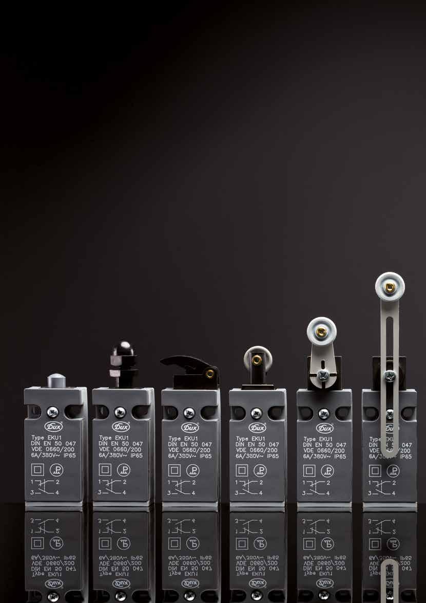
5 EKU IP IP IP IP IP IP 1NC + 1NO mm EKU1-KST EKU1-KD EKU1-KG EKU1-KH EKU1-KR 1NC + 1NO snap action contact m m 0 12, 2 0 EKU1-SPR-KST EKU1-SPR-KD EKU1-SPR-KFS EKU1-SPR-KG EKU1-SPR-KH EKU1-SP KRH 1NC + 1NO slow action contact mm EKU1-FD-KST EKU1-FD-KD EKU1-FD-KG EKU1-FD-KH n recommended operating travel m positive opening If you require a cable gland, just add mkv to type number (e.g. EKU1-KSTmKV). o The EKU series are also available for AS-Interface applications. 636 Georg Schlegel GmbH & Co. KG Dürmentingen (0) 3 1 / Fax: +49 (0) 3 1 / info@schlegel.biz -
6 IP IP IP IP IP IP IP IP H EKU1-KRHV EKU1-KK EKU1-KDH EKU1-KDF EKU1-KR EKU1-KV EKU1-KW EKU1-KZ R- EKU1-SPR- KRHV EKU1-SPR-KK EKU1-SPR-KDH EKU1-SPR-KDF EKU1-SPR-KR EKU1-SPR-KV EKU1-SPR-KW EKU1-FD-KK EKU1-FD-KR EKU1-FD-KV EKU1-FD-KW Georg Schlegel GmbH & Co. KG Dürmentingen (0) 3 1 / Fax: +49 (0) 3 1 / info@schlegel.biz
7 EKU EKU1-KST EKU1-FD-KST EKU1-SPR-KST EKU1-KD EKU1-SPR-KD EKU1-FD-KD ø 6 Hub, ø18 6 Hub 12 4,3 20±0,1 ±0,1 2 4,3 20±0,1 ±0,1 2 EKU1-SPR-KFS ø4 EKU1-KG EKU1-SPR-KG EKU1-FD-KG , ,3 20±0,1 4,3 20±0,1 ±0,1 2 ±0,1 2 EKU1-KH EKU1-SPR-KH EKU1-FD-KH EKU1-KRH EKU1-SPR-KRH ø16 36, R20, , 24 3, 4,3 4,3 20±0,1 20±0,1 ±0,1 2 ±0,1 2 6 Georg Schlegel GmbH & Co. KG Dürmentingen (0) 3 1 / Fax: +49 (0) 3 1 / info@schlegel.biz -
8 EKU EKU1-KRHV EKU1-SPR-KRHV EKU1-KK EKU1-SPR-KK EKU1-FD-KK Ø16 36, 18 4,3 20±0,1 ±0,1 8, 2 min. 0 / max , 36, 4,3 R, R, 20 ±0,1 ±0,1 2 EKU1-KDH EKU1-SPR-KDH EKU1-KDF EKU1-SPR-KDF EKU1-KR EKU1-SPR-KR EKU1-FD-KR 8 ø6 42 ø16 Hub 8, max ,3 20±0,1 ±0, ,3 20±0,1 ±0,1 2 EKU1-KV EKU1-SPR-KV EKU1-FD-KV EKU1-KW EKU1-SPR-KW EKU1-FD-KW ø Hub 20 SW R20, 4 4,3 20±0,1 ±0,1 2 4,3 20±0,1 ±0,1 2 Georg Schlegel GmbH & Co. KG Dürmentingen (0) 3 1 / Fax: +49 (0) 3 1 / info@schlegel.biz
9 EKU EKU1-KZ 4,3 20±0,1 ±0,1 ø Georg Schlegel GmbH & Co. KG Dürmentingen (0) 3 1 / Fax: +49 (0) 3 1 / info@schlegel.biz -
10 Description Definition Limit switches are also dealt under position switches or limiting switches or limit stop switches. However, behind all these terms hides a switchgear which is primarily used to protect man and machine. Characteristics of DUX Limit Switches These limit switches offer quite a number of actuators to be selected according to the required mode of operation. They are used in auxiliary and pilot circuits and are excellently suitable for the control and movement limitation, e.g. in machine tools and processing machines, lifts, conveyor systems, vehicles, cranes, technical building equipments as well as trigger switches in safety and alarm systems, and many more. The limit switches are available in various designs and materials and can such be used in different fields of application and environmental conditions. In order to meet the diverse equipment controlling requirements, a multitude of contact configurations can be implemented to provide optimal solutions for nearly all mechanical switching requirements. The variety of actuators, which are rotatable by 90, providing high flexibility for each particular case of application. Set-up and Operation of Limit Switches Limit switch and plunger drive should only be used when the switching point is subject to a tight tolerance range. The actuation movement should preferably be in the same direction as the plunger movment. The limit switches are constructed in a way that they may in no case be used as a mechanical limit stop. The reset force for other movable actuating appliances (such as flaps, doors, etc.) must not be taken from the actuator of the limit switch, because it was only designed for the plunger reset of the limit switch. In order to guarantee an optimal switching action the max. operating angles of the different actuators must be observed. The cam of the respective machine must actuate the plunger only in the permissible level. The over-travel of the actuator may only be used as shown in the relative switch travel diagram. It is not permitted to shorten the working travel by operating the actuator in advance. The reset movement of the actuator must be guided by the return movement of the machine s cam, i.e. the actuator must not spring back freely to its original position. The length of the actuating cam must be selected so that an actuating time with double safety is achieved. If e.g. the response time of the operated auxiliary contactor to its latching position is ms, the min. actuating time of the limit switch should be ms. Limit Switch Mounting Limit switches have to be mounted to be easy accessible and shockresistant, following the a.m. instructions. To guarantee the specified degree of protection, the lid screws must be tightened evenly and the cable entry must be fixed appropriately according to the cable diameter. The limit switches must be used under strict observance of the relative parameters and rules of application. Depending on the number of switching actuations and operating conditions, the operational reliability of the switches has to be checked regularly. Due to the flexible AS-Interface network structure, the DUX limit switches designed for AS-Interface application can be connected in any position. Each limit switch acts as a separate node with individual address within the AS-Interface network. switching actuations and operating conditions, the operational reliability of the switches has to be checked regularly. Due to the flexible AS-Interface network structure, the DUX limit switches designed for AS-Interface application can be connected in any position. Each limit switch acts as a separate node with individual address within the AS-Interface network. Technical Data of Limit Switches for AS-Interface Application Communication - AS-Interface specification: V2.11, Rev. 1 - Slave profile: S-B.A.E - Connection: 4-pole sensor connector M12x1, contact 1is assigned to ASI+ and contact 3 to ASI- - Max. network length: 0m (without repeater) - Max. cycle time: ms (62 A/B slaves) Ambient Conditions - Transport-, storage- and Operating temperature: -2 C... + C Mechanical Data - Operating travel: 6mm Electrical Data - Voltage supply: V, through the AS-Interface line Total power consumption: <= ma - Reverse polarity protection: available Admissible on-load switching cycles: 1200/h Mechanical life: mill. switching cycles Operating force on plunger N Actuators: exchangeable and rotatable by 90 Degree of protection acc. to DIN 00: IP Construction: compliant to VDE 0660/200 Ambient conditions stationary use at weatherproof locations acc. to DIN IEC D6/3Z2/3Z/3B2/3C2/3S3/3M6 Georg Schlegel GmbH & Co. KG Dürmentingen (0) 3 1 / Fax: +49 (0) 3 1 / info@schlegel.biz
11 IP IP IP IP IP IP 1NC + 1NO m m ASI_EKU1-KST ASI_EKU1-KD ASI_EKU1-KG ASI_EKU1-KH ASI_EKU1-1NC + 1NO snap action contact m m 0 12, 2 0 ASI_EKU1-SPR- KST ASI_EKU1-SPR- KD ASI_EKU1-SPR- KFS ASI_EKU1-SPR- KG ASI_EKU1-SPR- KH ASI_EKU1- KRH n recommended operating travel m positive opening 642 Georg Schlegel GmbH & Co. KG Dürmentingen (0) 3 1 / Fax: +49 (0) 3 1 / info@schlegel.biz -
12 IP IP IP IP IP IP IP IP KRH ASI_EKU1- KRHV ASI_EKU1-KK ASI_EKU1-KDH ASI_EKU1-KDF ASI_EKU1-KR ASI_EKU1-KV ASI_EKU1-KW ASI_EKU1-KZ SPR- ASI_EKU1-SPR- KRHV ASI_EKU1-SPR- KK ASI_EKU1-SPR- KDH ASI_EKU1-SPR- KDF ASI_EKU1-SPR- KR ASI_EKU1-SPR- KV ASI_EKU1-SPR- KW Georg Schlegel GmbH & Co. KG Dürmentingen (0) 3 1 / Fax: +49 (0) 3 1 / info@schlegel.biz
13 Limit Switches 4,3 ø18 ±0,1 2 20±0, ASI_EKU1-KD ASI_EKU1-SPR-KD 6 Hub ASI_EKU1-KST ASI_EKU1-SPR-KST ASI_EKU1-SPR-KFS ASI_EKU1-KG ASI_EKU1-SPR-KG ASI_EKU1-KH ASI_EKU1-SPR-KH ASI_EKU1-KRH ASI_EKU1-SPR-KRH Georg Schlegel GmbH & Co. KG Dürmentingen (0) 3 1 / Fax: +49 (0) 3 1 / info@schlegel.biz -
14 Limit Switches ASI_EKU1-KRHV ASI_EKU1-SPR-KRHV ASI_EKU1-KK ASI_EKU1-SPR-KK ASI_EKU1-KDH ASI_EKU1-SPR-KDH ASI_EKU1-KDF ASI_EKU1-SPR-KDF ASI_EKU1-KR ASI_EKU1-SPR-KR ASI_EKU1-KV ASI_EKU1-SPR-KV ASI_EKU1-KW ASI_EKU1-SPR-KW Georg Schlegel GmbH & Co. KG Dürmentingen (0) 3 1 / Fax: +49 (0) 3 1 / info@schlegel.biz
15 ASI_EKU1-KZ 646 Georg Schlegel GmbH & Co. KG Dürmentingen (0) 3 1 / Fax: +49 (0) 3 1 / info@schlegel.biz -
16 K Limit Switches - K... Series Type approval GL Operating and ambient conditions compliant to DIN IEC and DIN IEC Degree of protection acc. to DIN 00 IEC 144 IP Contact base material PA6 Transport, storage and operating temperature -2 C up to + C Screw clamp connection M 3. Terminal cross-section 2x mm² solid, flexible multicore with ferrule 2x mm² Operating speed on plunger max. 0.2 m/s min. 1mm/s AC; min. 20mm/s DC Mechanical life 1x switching cycles Operating force on plunger N Insulation group acc. to DIN VDE 1 C Admissible on-load switching cycles 1200/h Min.switching current using silver contacts 0.1A with slow-action contact 0.012A with snap-action contact 0.012A Min.switching voltage using silver contacts 24V Electrical life x switching cycles AC 0V/1A DC 0V/0,2A Max.rated current/ AC 6A Rated frequency Hz Max.rated voltage AC 0V DC 0V Georg Schlegel GmbH & Co. KG Dürmentingen (0) 3 1 / Fax: +49 (0) 3 1 / info@schlegel.biz
17 K IP IP IP IP 1NC mm KA1 KA1-D KA1-G 1NC + 1NO mm KU1 KU1-D KU1-G 1NC + 1NO (overlapping) / mm KÜ1 KÜ1-D KÜ1-G 1NC + 1NO slow action contact mm KU1-FD KU1-FD-D KU1-FD-G 1NC + 1NO snap action contact m m 0 12, 2 0 KU1-SP KU1-SP-D KU1-SP-FS KU1-SP-G 2NC m KA2 KA2-D KA2-G 2NC + 1NO mm /6 KA2-E1 KA2-E1-D KA2-E1-G 2NO / mm KE2 KE2-D KE2-G 1NC + 2NO mm /6 KE2-A1 KE2-A1-D KE2-A1-G 1NC + 1NO slow action contact / mm KA1-E1-FD KA1-E1-FD-D KA1-E1-FD-G n recommended operating travel m positive opening 648 Georg Schlegel GmbH & Co. KG Dürmentingen (0) 3 1 / Fax: +49 (0) 3 1 / info@schlegel.biz -
18 IP IP IP IP IP IP KA1-H KA1-K KA1-R KA1-V KA1-W KU1-H KU1-K KU1-R KU1-V KU1-W KU1-Z KÜ1-H KÜ1-K KÜ1-R KÜ1-V KÜ1-W KU1-FD-H KU1-FD-K KU1-FD-R KU1-FD-V KU1-FD-W KU1-SP-H KU1-SP-K KU1-SP-R KU1-SP-V KU1-SP-W KA2-H KA2-K KA2-R KA2-V KA2-W KA2-E1-H KA2-E1-K KA2-E1-R KA2-E1-V KA2-E1-W KE2-H KE2-K KE2-R KE2-V KE2-W KE2-A1-H KE2-A1-K KE2-A1-R KE2-A1-V KE2-A1-W KA1-E1-FD-H KA1-E1-FD-K KA1-E1-FD-R KA1-E1-FD-V KA1-E1-FD-W If you require a cable gland, just add mkv to type number (e.g. KA1mKV). If you want to have the limit switches with GL approval, just add T in front of type number (e.g. T-KA1). Georg Schlegel GmbH & Co. KG Dürmentingen (0) 3 1 / Fax: +49 (0) 3 1 / info@schlegel.biz
19 K KA1 KU1 KU1-FD KU1-SP KA2 KA2-E1 KE2 KE2-A1 KA1-E1-FD KÜ1 ø Hub ø 6 Hub, 6, , 6, KA1-D KU1-D KU1-FD-D KU1-SP-D KA2-D KA2-E1-D KE2-D KE2-A1-D KA1-E1-FD-D KÜ1-D ø18 Hub 6, 6 ø18 6 Hub , KA1-G KU1-G KU1-FD-G KU1-SP-G KA2-G KA2-E1-G KE2-G KE2-A1-G KA1-E1-FD-G KÜ1-G 12, 12, , , 63 0 Georg Schlegel GmbH & Co. KG Dürmentingen (0) 3 1 / Fax: +49 (0) 3 1 / info@schlegel.biz -
20 K KA1-H KU1-H KU1-FD-H KU1-SP-H KA2-H KA2-E1-H KE2-H KE2-A1-H KA1-E1-FD-H KÜ1-H R20, 20 R20, , 6, KA1-K KU1-K KU1-FD-K KU1-SP-K KA2-K KA2-E1-K KE2-K KE2-A1-K KA1-E1-FD-K KÜ1-K 44, 36, R, R, , R, R, , 6, KA1-R KU1-R KU1-FD-R KU1-SP-R KA2-R KA2-E1-R KE2-R KE2-A1-R KA1-E1-FD-R KÜ1-R ø16 Hub ø16 Hub , 6, Georg Schlegel GmbH & Co. KG Dürmentingen (0) 3 1 / Fax: +49 (0) 3 1 / info@schlegel.biz - 1
21 K KA1-V KU1-V KU1-FD-V KU1-SP-V KA2-V KA2-E1-V KE2-V KE2-A1-V KA1-E1-FD-V KÜ1-V ø Hub ø Hub SW SW , 6, KA1-W KU1-W KU1-FD-W KU1-SP-W ø16 12, 20 KA2-W KA2-E1-W KE2-W KE2-A1-W KA1-E1-FD-W KÜ1-W ø , R , R18 12, , 6, KU1-Z KU1-SP-FS ø ,3 ø ±0,1 ±0,1 2 6, Georg Schlegel GmbH & Co. KG Dürmentingen (0) 3 1 / Fax: +49 (0) 3 1 / info@schlegel.biz -
22 GW/PW Limit Switches - GW...1 Standard Series Type Approval GL Operating and ambient conditions compliant to DIN IEC and DIN IEC Degree of protection acc. to DIN 00 IEC 144 IP Housing material aluminium die casting Transport, storage and operating temperature -2 C up to + C Screw clamp connection M 4 Terminal cross-section 2x mm² solid, flexible multicore with ferrule 2x mm² Operating speed on plunger max. 0.2 m/s min. 1mm/s AC; min. 20mm/s DC Mechanical life 1x switching cycles Operating force on plunger 18N Insulation group acc. to DIN VDE 1 C Admissible on-load switching cycles 1200/h Min. switching current using silver contacts 0.1A Min. switching voltage using silver contacts 24V Electrical life x switching cycles AC 0V/1A DC 0V/0,2A Max. rated current/ AC 6A Rated frequency Hz Max. rated voltage AC 0V DC 0V Limit Switches - GW...2 Modular Series Module type approval -- Operating and ambient conditions compliant to DIN IEC and DIN IEC Degree of protection acc. to DIN 00 IEC 144 IP Housing material aluminium die casting Contact base material PA6.6 Transport, storage and operating temperature -2 C up to + C Screw clamp connection Schlegel Modular Contact System Screwless connection technology CAGE CLAMP Modular Contact System Operating speed on plunger max. 0.2 m/s min 1mm/s AC min 20mm/s DC Mechanical life -- Operating force on plunger 18N Admissible on-load switching cycles 1200/h The possible combinations of the modular contact elements create a modular assembly system that offers a variant diversity which is unique. For instance, for connection workings the modular contact block can be freely removed from the housing, which makes wiring very easy. Limit Switches - PW... Series Operating and ambient conditions compliant to DIN IEC Degree of protection acc. to DIN 00 IEC 144 IP Housing material PA6 Transport, storage and operating temperature -2 C up to + C Screw clamp connection M 4 Terminal cross-section 2x mm² solid, flexible multicore with ferrule 2x mm² Operating speed on plunger max. 0,2 m/s min. 1mm/s AC; min. 20mm/s DC Mechanical life 1x switching cycles Operating force on plunger 18N Insulation group acc. to DIN VDE 1 C Admissible on-load switching cycles 1200/h Min.switching current using silver contacts 0.1A Min.switching voltage using silver contacts 24V Electrical life x switching cycles AC 0V/1A DC 0V/0,2A Max.rated current/ AC 6A Rated frequency Hz Max. rated voltage AC 0V DC 0V Georg Schlegel GmbH & Co. KG Dürmentingen (0) 3 1 / Fax: +49 (0) 3 1 / info@schlegel.biz - 3
 + 1NC 0 1 2 3 4 6 m GWÜA1 GWÜA1-H 1NC + 1NO (overlapping) + 1NO 0 1 2 3 4 6 m GWÜE1 GWÜE1-H 2NC 6 0 1 2 3 4 mm")

. 4 Georg Schlegel GmbH & Co.")
23 GW/PW IP IP IP 1NC GWA1 GWA1-H mm PWA1 PWA1-H 1NC + 1NO GWU1 PWU1 GWU1-D GWU1-H PWU1-H 1NC + 1NO (overlapping) m GWÜ1 GWÜ1-D GWÜ1-H NC + 1NO (overlapping) + 1NC m GWÜA1 GWÜA1-H 1NC + 1NO (overlapping) + 1NO m GWÜE1 GWÜE1-H 2NC mm GWA2 GWA2-D GWA2-H 2NC + 1NO m m GWA2-E1 GWA2-E1-D GWA2-E1-H 2NC, positive opening contact mm GWA2-Zw GWA2-H-Zw 2NC + 2NO m m GWU2 GWU2-D GWU2-H 2NO GWE2 GWE2-D GWE2-H 3NC m GWA3 GWA3-D GWA3-H 3NO m GWE3 GWE3-D GWE3-H If you require a cable gland, just add mkv to type number (e.g. GWA1mKV). If you want to have the limit switches with GL approval, just add T in front of type number (e.g. T-GWA1). 4 Georg Schlegel GmbH & Co. KG Dürmentingen (0) 3 1 / Fax: +49 (0) 3 1 / info@schlegel.biz -


 3 1 / 02-0 - Fax: +49")
24 IP IP IP IP GWA1-R GWA1-V PWA1-R GWU1-R PWU1-R GWU1-V GWU1-F GWU1-ZB PWU1-ZB GWÜ1-R GWÜ1-V GWÜ1-F GWÜA1-R GWÜE1-R GWA2-R GWA2-V GWA2-F GWA2-E1-H GWA2-E1-V GWA2-E1-F GWA2-R-Zw GWA2-V-Zw GWU2-R GWU2-V GWU2-F GWE2-R GWE2-V GWE2-F GWA3-R GWA3-V GWA3-F GWE3-R GWE3-V GWE3-F n recommended operating travel m positive opening Georg Schlegel GmbH & Co. KG Dürmentingen (0) 3 1 / Fax: +49 (0) 3 1 / info@schlegel.biz -
25 GW/PW GWA1 GWA2 GWE3 GWU1 GWA2-E1 GWÜ1 PWA1 GWA2-Zw GWÜA1 PWU1 GWU2 GWÜE1 GWE2 GWA3 1. ø8 1), 1, ø8, ,2 1, , GWA1-H GWU1-H PWA1-H PWU1-H 9 ø20 GWA2-H-Zw GWU2-H GWE2-H GWA3-H GWE3-H GWA2-H 9 1, GWA2-E1-H GWÜ1-H GWÜA1-H GWÜE1-H ø , 1, 28 R2 4 16,, 28 R2 1,2 1,2 16, , GWA1-R GWU1-R PWA1-R PWU1-R GWA2-R GWU2-R GWE2-R GWA3-R GWE3-R GWA2-E1-R GWÜ1-R GWÜA1-R GWÜE1-R GWA2-R-Zw 3, 1, ø16 3, 1, ø16,, 1,2 1, , 6 Georg Schlegel GmbH & Co. KG Dürmentingen (0) 3 1 / Fax: +49 (0) 3 1 / info@schlegel.biz -
26 GW/PW GWU1-D GWA2-D GWU2-D GWE2-D GWE3-D GWÜ1-D GWA3-D GWA2-E1-D 1, ø32 ø32 1, 34, 34, 1,2 1, , GWU1-F GWA2-F GWU2-F GWE2-F GWA3-F GWE3-F 28 GWÜ1-F GWA2-E1-F ,, 1,2 1, , GWU1-V GWA1-V SW 8 SW ø8 1, 28 ± 1,, GWA2-V GWA2-V-Zw GWU2-V GWE2-V GWE3-V GWÜ1-V ø8 SW8 SW 1, 28 ± 1, GWA2-E1-V GWA3-V, 1,2 1, , Georg Schlegel GmbH & Co. KG Dürmentingen (0) 3 1 / Fax: +49 (0) 3 1 / info@schlegel.biz -
27 GW/PW GWU1-ZB PWU1-ZB 29 ø4 1,2, ø8 1, 8 Georg Schlegel GmbH & Co. KG Dürmentingen (0) 3 1 / Fax: +49 (0) 3 1 / info@schlegel.biz -
28 O / P Limit Switches - O/P...Series Operating and ambient conditions compliant to DIN IEC Degree of protection for P... series acc. to DIN 00 IEC 144 IP Degree of protection for O...series acc. to DIN 00 IEC 144 IP 00 Contact base material PA6 Cover material (only on P...series) PC Transport, storage and operating temperature -2 C up to + C Screw clamp connection M 4 Terminal cross-section 2x mm² solid, flexible multicore with ferrule 2x mm² Operating speed on plunger max. 0.2 m/s min. 1mm/s AC; min. 20mm/s DC Mechanical life 1x switching cycles Operating force on plunger P1/O1=N P2/O2=16N Insulation group acc. to DIN VDE 1 C Admissible on-load switching cycles 1200/h Min.switching current using silver contacts 0.1A Min.switching voltage using silver contacts 24V Electrical life x switching cycles AC 0V/1A DC 0V/0,2A Max.rated current/ac 6A Rated frequency Max.rated voltage Hz AC 0V DC 0V IP00 IP IP00 IP 1NC + 1NO mm OU1 PU1 OU1-R PU1-R 2NC mm PA2 PA2-R 2NO PE2 PE2-R 1NC + 1NO (overlapping) m PÜ1 PÜ1-R n recommended operating travel m positive opening Georg Schlegel GmbH & Co. KG Dürmentingen (0) 3 1 / Fax: +49 (0) 3 1 / info@schlegel.biz - 9
29 O / P OU1 PU1 ø8, ø , ø4, 3 18, ø4, 3, , PA2 PE2 PÜ1 PU1-R ø8 19, a 12 16, 3 3, 8 b 3, , ø4, 3, 12 8 Typ Maß PA2 PE2 PÜ1 a 14 b OU1-R 16, 3 PA2-R PE2-R PÜ1-R 3 18, 3, 3 8 b 4, a 18 3, 3, Typ Maß PA2 PE2 PÜ1 a 14 b Georg Schlegel GmbH & Co. KG Dürmentingen (0) 3 1 / Fax: +49 (0) 3 1 / info@schlegel.biz -
30 Illustration Dimensions Description Type Actuator: rotary lever with spring rod KDF for the EKU.. and K.. series Actuator: rotary lever with fibreglass rod for the EKU.. and K.. series KDH Actuator: sliding lever KG for the EKU.. and K.. series Actuator: lever KH for the EKU.. and K.. series Actuator: toggle lever KK for the EKU.. and K.. series Actuator: short roller set lever KRH for the EKU.. and K.. series Actuator: adjustable roller set lever KRHV for the EKU.. and K.. series Georg Schlegel GmbH & Co. KG Dürmentingen (0) 3 1 / Fax: +49 (0) 3 1 / info@schlegel.biz
31 Illustration Dimensions Description Type Actuator: angular lever KW for the EKU.. and K.. limit switches Actuator: lever GWH for the GW.. series Actuator: lever PWH für Baureihe PW Dummy Plug BS-EK for the EKU series cable feedthrough KD-K for the K.. series Screwed cable gland with insulation displacement connection (IDC) SNT for the EKU... series Cable Gland M16x1. M20x1, M2x1, KV-M16x1, KV-M20x1, KV-M2x1, Screw plug M16x1, M20x1, M2x1, VS-M16x1, VS-M20x1, VS-M2x1, 662 Georg Schlegel GmbH & Co. KG Dürmentingen (0) 3 1 / Fax: +49 (0) 3 1 / info@schlegel.biz -
32 Georg Schlegel GmbH & Co. KG Dürmentingen (0) 3 1 / Fax: +49 (0) 3 1 / info@schlegel.biz
Recommended use With its standard enclosure, the ENM2 limit switch can be used universally in all industrial and safety applications.
 Metal-Enclosed Limit Switches ENM2 Recommended use With its standard enclosure, the ENM2 limit switch can be used universally in all industrial and safety applications. Product advantages Standard switch
Index. Manual Motor Starters 1. Auxiliary Contact Blocks 1. Trip Alarm Auxiliary 1. Switch. Shunt Release 1. Under-voltage Release 2.
 Index Index Page Manual Motor Starters 1 Auxiliary Contact Blocks 1 Trip Alarm Auxiliary 1 Switch Shunt Release 1 Under-voltage Release 2 Accessories 2 Busbar Connectors 2 Enclosures 2 Leistung, kw C mv
Floor and fine adjustment switches
 Floor and fine adjustment switches 6 Introduction 6-2 AS 1 6-3 ASH 2 6-4 AFH 2 6-5 Reference table technical data 6-6 Universal switches 6-7 Floor and fine adjustment switches / Introduction ➀ ➁ ➂ Floor
Control Equipment. ATHEX bvba Tel: +32 (0) Fax: +32 (0) Alpenroosbaan 2, 2900 Schoten, België
 Fax: +32 (0) Alpenroosbaan 2, 2900 Schoten, België") Control Equipment 01616E00 Position switches are used to monitor the position of moving parts of machines and plant. Can be used in safety circuits, as the device satisfies EN 60 947-5-1/DIN VDE 0660 part
Control Equipment 01616E00 Position switches are used to monitor the position of moving parts of machines and plant. Can be used in safety circuits, as the device satisfies EN 60 947-5-1/DIN VDE 0660 part
SERIES MINIATURE SNAP-ACTION SWITCHES
 PRODUCT FEATURES The precise mounting of the moving contact part (milled bearing blade) offers optimum snap-action even with slow actuation Wide range of ratings from 3 (1) A 250 V AC to 21 (8) A 250 V
3SE3 2 SIGUARD Position Switches
 3E3 2 IGUARD Position witches Description Application The function of position switches (limit switches) is to produce electrical signals corresponding to the positions by moving machinery. The units are
Micro Contactor MA Series
 Relay-sized contactor, making it the world s smallest >3mm contact clearance acc. to IEC 60335-1 for Safety Applications Reversing contactor with mechanical interlock 3 Pole and 1 Aux. Contact NO or NC
Miniaturized limit switches
 Miniaturized limit switches Selection diagram Actuators 04 0 06 Thermoplastic Bodies M3 Contact blocks NONC 1NO+1NC snap action Cable entry With screw 290 GENERAL CATALOGUE miniaturized limit switches
Position and Safety Switches
 Siemens AG 20 Position and Safety Switches groups 41K, 42A /2 Introduction SIRIUS 3SE5 mechanical position switches /4 General data 3SE5, plastic enclosures /13 - Enclosure width 31 mm acc. to EN 50047
Limit Switches and Safety
 and Safety Introduction Overview 3SE5 23., 3SE5 21. 3SF1 2.4 3SE5 24., 3SF1 244 3SE5 13., 3SE5 11., 3SF1 114 3SE5 12., 3SF1 124 3SE5 16. 3SE5 232, 3SE5 212, 3SF1 2.4 3SE5 132, 3SE5 112, 3SF1 1.4 Position
Position Switches Series 8074/2
 www.stahl.de > Ex e metal enclosure > Operating temperature range -40 C... +70 C > Dimensions and characteristic values according to EN 50041 > Degree of protection IP66 > Extensive assortment of actuators,
FL series position switches
 FL series position switches Selection diagram 0 08 0 9 0 0 0 Ball Ø. External rubber Ball Ø 8 mm, mm, stainless Glass fibre rod gasket stainless steel steel Adjustable lever Adjustable safety lever Bistable
Limit switches. 7 Page 71. Presentation. OsiSense XC Basic Compact design, plastic, with reset knob, types XCNR and XCNTR. b XCNR.
 Presentation Compact design, plastic, with reset knob, types XCNR and XCNTR b XCNR with cable entry v With head for linear movement (plunger) Page v With head for rotary movement (lever) Page b XCNTR with
SIGUARD Safety Systems Safety Integrated
 / 3SE2 303 / 3SE2 404 and open type SIGUAR Safety Systems Safety Integrated Application The function of the position switches (limit switches) is to produce electrical signals corresponding to the positions
Pre wired limit switches
 Pre wired limit switches Selection diagram Actuators A B B 9 BL Thermoplastic Bodies E7 I s NO+NC snap action NO+NC slow action Cable entry 4 or 5 pole PVC sheath cable (standard) M connector AMP connector
Double insulated, types XCK-P and XCK-T. With head for linear movement (plunger) operators
 operators") Double insulated, types XCK-P and XCK-T Presentation XCK-P with 1 cable entry, conforming to CENELEC EN 57 With head for linear movement (plunger) operators Page 18 With head for rotary movement (lever)
Double insulated, types XCK-P and XCK-T Presentation XCK-P with 1 cable entry, conforming to CENELEC EN 57 With head for linear movement (plunger) operators Page 18 With head for rotary movement (lever)
General Data Type Reference: Electronic contact block with PCB-mount terminals, with snap action CCC, ccsaus, GOST-R, NV, CE, UkrSepro
 486 General Data Type Reference: CTP... Description: Electronic contact block with, with snap action Approvals: CCC, ccsaus, GOST-R, NV, CE, UkrSepro Protection class: II (protective insulation) Operation
Position Switches Series 8070/2
 www.stahl.de > Ex e plastic enclosure > Operating temperature range -60 to +60 C > Dimensions and characteristic values according to EN 50041 > Degree of protection IP66 / IP67 > Extensive assortment of
SERIES SUBMINIATURE SNAP-ACTION SWITCHES
 PRODUCT FEATURES Small, effi cient snap-action switch up to 10 (1.) A 20 V AC or 10.1 A 12-20 V AC 1/4 HP Lateral approach from both directions possible due to mushroom-shaped actuator Large selection
Installation and Operating Instructions
 Plastic encased safety interlocking switch Type PSEN me2/psen me3 Intended use The plastic encased safety switches PSEN me2 and PSEN me3 with separate actuator are suitable for the mounting on safety guards.
Selection diagram. Actuators. Body. Contact blocks. Cable entry A A S1 B B 13. Thermoplastic
 Limit switches Selection diagram Actuators A A S B B G L LP LS Thermoplastic Body E0 I E20 I E40 I Contact blocks (standard) M20 ½ NPT 00 NO+NC snap action 0 NO+NC slow action 02 NO+NC slow action with
Position switches FD series
 Position switches FD series Selection diagram 01 08 11 18 19 02 04 05 Ø 8 mm Ø, mm external rubber stainless steel stainless steel fibber glass rod gasket sphere sphere 51 52 5 56 41 42 adjustable lever
General Data. Electrical data acc. to IEC/EN (VDE 0660 Sect. 200)
") 450 General Data Type Reference: BZ... (without screw connection) Description: Twin Contact Block, separate plungers, positive opening contact Approvals: CCC, ccsaus, ENEC10, VDE, CE, NV, TÜV_Süd, positive
450 General Data Type Reference: BZ... (without screw connection) Description: Twin Contact Block, separate plungers, positive opening contact Approvals: CCC, ccsaus, ENEC10, VDE, CE, NV, TÜV_Süd, positive
D509E. Manual Motor - Starters
 D509E Manual Motor - Starters Index Page Manual Motors Starters 182 Auxilliary Contact Blocks 182 Trip Alarm Aux. Switch 182 Shunt Release 182 Under-voltage Release 183 Accessories 183 Busbar Connectors
Series 20 D. Pressure switches for all-fluid technique Port sizes G 1 /4 and G 1 /2
 Series 0 D Pressure switches for all-fluid technique Port sizes and Microswitch with gold-plated contacts (silver plated for outdoor variants) Plug-in connection to DIN 4650 Technical Data Fluid: Neutral
Solenoid interlocks AZM 190 range. 128 Schmersal ,3 4,5 M20 17,5 23,5
 2.19 AZM 19 range 13 44 32 2,3 3 1 Features Voltage variants Approvals Thermoplastic enclosure Manual / Emergency release Long life Actuation on de-energisation or energisation Slim design, particularly
SERIES SINGLE AND DOUBLE-POLE ROCKER SWITCHES
 TO 1 (4) A 50 V AC ROCKER SWITCHES PRODUCT FEATURES 100 million times proven switching principle High, fl exible design variety Excellent actuating characteristic Illuminated and non-illuminated variants
Position switches FC series
 A Position switches FC series Selection diagram 0 08 8 9 0 0 0 Ø 8 mm Ø, mm external rubber stainless steel stainless steel fiber glass rod gasket sphere sphere 6 adjustable lever safety adjustable lever
Solenoid interlocks AZM 170 range. 98 Schmersal 22 8,2 60. ø4,2. ø Pg 11
 2.4 AZM 170 range Features Thermoplastic enclosure Compact design Manual release Long life Double insulated X High holding force 1,000 N N latching force Cut clamp termination Actuation on de-energisation
Installation and Operating Instructions
 Plastic encased safety interlocking switch Type PSEN me4 Intended use The plastic encased safety switches PSEN me4 with separate actuator are suitable for the mounting on safety guards. They are designated
High-pressure switch for gas, air, flue gases and combustion products GW 500 A4 GW A4/2 HP
 High-pressure for gas, air, flue gases and combustion products HP /2 HP 5.04 Printed in Germany Rösler Druck Edition 06.04 Nr. 241 654 1 6 Technical description The pressure is an adjustable pressure for
Series S847 Changeover switches featuring wiping, galvanically isolated, double-break contacts and positive opening operation Catalogue D47.
 Snap-action switches Changeover switches featuring wiping, galvanically isolated, double-break contacts and positive opening operation Catalogue D47.en Snap-action switches, S847 Series Dual changeover
Miniature microswitches - Positive break
 1 Miniature microswitches - Positive break 81607 Coil spring snap-action mechanism with wiping contacts Positive opening action according to IEC 6097-5-1 Annex K atings from 10 ma Vc to 6 A 250 Va Very
Position switches FR series
 Position switches FR series Selection diagram 01 A1 08 14 01-7 0 A 05 A5 external rubber gasket external rubber gasket for electrical panels external rubber gasket external rubber gasket 0 1 5 34 50 33
S826, S926 Series Dual changeover switches with positive opening operation and wiping contacts Catalogue D26.en
 2 Snap-action switches S826, S26 Series Dual changeover switches with positive opening operation and wiping contacts Catalogue D26.en 2 Snap-action switches S826 Series Dual changeover switches with positive
Approved Standards. Ordering Information. Mini Motor Contactor J7KNA. Model Number Legend. Main contactor. Accessories. Mini Motor Contactor J7KNA 1
 Mini Motor Contactor J7KNA ) Main contactor AC & DC operated Integrated auxiliary contacts Screw fixing and snap fitting (35 mm DIN-rail) Range from 4 to 5.5 (AC 3, 380/415V) 4 -main pole version (4 AC
Solenoid interlocks AZM 161 range Schmersal. a 5,5. Pg11/M16x1,5
 .1 AZM 11 range Features Thermoplastic enclosure Manual and emergency release Long life Double insulated X High holding force, N N latching force Wiring compartment Actuation on de-energisation or energisation
SD, SE, SDE, SCO series Multipole switchgear for rail vehicles: Disconnecting switches, Earthing Switches, Disconnector with Earthing Switches,
 4 Electrics for Rolling Stock Multipole switchgear for rail vehicles: Disconnecting switches, Earthing Switches, Disconnector with Earthing Switches, Change-Over-Switches 600 V to 3 kv Catalogue F84.en
ZB0050 / ZB0051 ZB0070 / ZB0071
 Operating instructions Safety Rope Emergency Stop Switches UK ZB0050 / ZB0051 ZB0070 / ZB0071 7390877 / 02 08/2013 Contents 1 Safety instructions...3 2 Installation / set-up...4 2.1 Applications...4 2.2
BETA Switching Switches and Light Indicators
 Siemens AG 2008 BETA Switching /2 Product overview /3 5TE8 control switches / 5TE4 pushbuttons /2 5TE5 light indicators /5 5TE8 ON/OFF switches /22 5TE9 busbars /24 5TE switch disconnectors Siemens ET
Approved Standards. Ordering Information. Thermal Overload Relay J7TKN. Model Number Legend. Thermal Overload Relay. Accessories
 Thermal Overload Relay J7TKN ) Thermal Overload Relay Direct and separate mounting Single phasing sensivity according to IEC 60947-4-1 Finger proof (BGV A2) Accessories Set for single mounting Approved
Safety switches for hinged doors
 4C Safety switches for hinged doors Selection diagram CONTACT BLOCKS 18 7 9 20 overlapped 1NO+ FD FL FC 21 22 33 34 2NO+1NC 3NC CONDUIT ENTRIES Threaded conduit entries (standard) With cable gland assembled
Limit Switch Type 4747
 Limit Switch Type 4747 Ex d flameproof enclosure with inductive or mechanical contacts for linear actuators or rotary actuators acc. to VDI/VDE 3845 General The Type 4747 Limit Switch issues an electrical
SENTRON Switching and Protection Devices Switch Disconnectors
 SENTRON Switching and Protection Devices Switch Disconnectors /2 Introduction 3K, 3KE, 3LD Switch Disconnectors 3K, 3KE Switch Disconnectors up to 1000 /4 General data /8 Floor mounting 3LD Main and EMERGENCY-STOP
Technical data. Standards: IEC/EN ; EN ISO ; EN 1088; BG-GS-ET-19
 1 echnical data echnical data, 1 0 3 1 104 7 90 Interlock with protection against incorrect locking hermoplastic enclosure contacts Manual release, emergency exit or emergency release Long life Double
Modular pneumatic valve island
 Modular pneumatic valve island Compact design Modular configuration High flexibility Simple exchange of valves (with P shut off, also possible during operation an option) Type 8640 can be combined with
Position switches FR series
 Position switches FR series Selection diagram 0 A 08 0-0 A A 0 A external rubber gasket external rubber gasket for electrical panels external rubber gasket external rubber gasket external rubber gasket
Limit Switch - Safety Type with pull button reset Plastic Body IP65 and Metal Body IP66
 Limit Switch - Safety Type with pull button reset Plastic Body IP65 and Metal Body IP66 Double Insulation (for thermoplastic type) High mechanical resistant Degree of protection IP65 (thermoplastic) IP66
S840, S845, S846 Series Single-break changeover, NC or NO contacts, positive opening operation and wiping action Catalogue D40.en
 Snap-action switches S80, S85, S86 Series Single-break changeover, NC or NO contacts, positive opening operation and wiping action Catalogue D0.en Snap-action switches, S80, S85, S86 Series Single-break
International approvals.
 E X - P L U G A N D R E C E P T A C L E A to 25 A plugs and receptacles plastic version for Zone 2 A good connection Providing electrical energy there, where it is most needed even in hazardous areas for
Super X Inline 3/2 and 5/2 Spool valves, solenoid and pilot actuated
 > > Port size: G/8 & G/4 > > Low and high power solenoid coil options > > End, side or face mounting solenoids > > Light weight corrosion resistant materials > > Option for manual override acting directly
4/3 proportional directional control valve, without position control, with on-board electronics (OBE)
") 4/3 proportional directional control valve, without position control, with on-board electronics (OBE) Type 4WRBAE..E.. /..W.. Nominal size (NG) 6, 10 Unit series 2X Maximum working pressure P, A, B 315
4/3 proportional directional control valve, without position control, with on-board electronics (OBE) Type 4WRBAE..E.. /..W.. Nominal size (NG) 6, 10 Unit series 2X Maximum working pressure P, A, B 315
Unused flameproof threads for cable glands have to be closed with certified plugs.
 E X - P L U G A N D R E C E P T A C L E 1 A Metallic Design for Zone 1 The explosion-protected light metal plug and receptacle devices can be used in the areas of Zone 1 and Zone 2 at no risk of explosion.
Selection diagram. Actuators. Body. Contact blocks. Cable entry A A S1 B B 13. Thermoplastic
 Limit switches Selection diagram Actuators A A S B B 3 H G L LP LS Thermoplastic Body E I E2 I E4 I Contact blocks (standard) M2 ½ NPT NO+NC snap action NO+NC slow action 2 NO+NC slow action with overlapping
made in germany RONDEX-JUWEL Supplement to catalogue 7-8
 made in germany RONDEX-JUWEL Supplement to catalogue 7-8 Index >> 01 Control unit series RONDEX-JUWEL page 02 Type Index Limit Switches Pedal Switches Terminal Blocks Enclosures Bus Technology Panel Mount
System 8. Solenoid Coils Armature Assemblies Valve Systems. Nass Controls LP Nass Magnet GmbH Precision Controls Kft.
 Solenoid Coils Armature Assemblies Valve Systems Nass Controls LP Nass Magnet GmbH Precision Controls Kft. Introduction......................................... Page 4-5 Solenoid Coil Width 22 mm Connection
l Snap-Action Switches
 Connect - Contact - Control 2 Brochure l Snap-Action Switches Snap-action switches I Page 2 Page 3 I Snap-action switches Double Safety A sky diver's life depends on his equipment. In case of emergency
Modular pneumatic valve unit
 Modular pneumatic valve unit Compact design Modular configuration High flexibility Type 8640 can be combined with Simple exchange of valves (with option P-shut-off - also possible during operation) Type
LK Position Switches TECHNICAL DATASHEET.
 LK Position Switches Technopolymer housing, one conduit entry Protection degree IP6 according to EN 60529 contact blocks available 46 actuators available Versions with stainless steel external parts Versions
SIRIUS Standard Position Switches Product Overview. sirius DETECTING
 SIRIUS Standard Position Switches Product Overview sirius DETECTING Always on the alert: SIRIUS detection devices A wide variety of information prevails in the field. To monitor it accurately, you need
Temperature switch. Switching output 2 transistors PNP Logger Ring buffer: 3518 data points Sampling time: s, Off (0)
") Temperature switch Swiss based Trafag is a leading international supplier of high quality sensors and monitoring instruments for measurement of pressure and temperature. Applications Machine tools Hydraulic
Temperature switch Swiss based Trafag is a leading international supplier of high quality sensors and monitoring instruments for measurement of pressure and temperature. Applications Machine tools Hydraulic
BSW , -493, -494 Mechanical Rotary Cam Switches. User's Guide. Mechanical Rotary Cam Switches BSW BSW BSW
 BSW 819-492, -493, -494 User's Guide Mechanical Rotary Cam Switches BSW 819-492 BSW 819-493 BSW 819-494 The CE Marking is your guarantee that our products meet the requirements of EC Directive 89/336/EC
Modular multiple foot switches PC series
 3 Modular multiple foot switches PC series Combination diagrams EMERGENCY PUSH BUTTON COMMERCIAL BOX ALUMINIUM PIPES CARRYING ROD ALUMINIUM PIPES HANDLE KIT STABILIZING PLATE DOUBLE CARRYING ROD COMMERCIAL
Safety rope switches with reset for emergency stop
 Safety rope switches with reset for emergency stop Selection diagram 8 8 83 ACTUATORS ACTUATORS CONTACT BLOCKS 18 9 21 1NO+ FP FD FL FC 22 33 34 LED signalling light CONDUIT ENTRIES For other available
Safety rope switch with reset for emergency stop
 Safety rope switch with reset for emergency stop Selection diagram 8 8 83 ACTUATORS ACTUATORS CONTACT BLOCKS 18 9 21 1NO+,, FP FD FL FC 22 33 34,, CONDUIT ENTRIES Threaded conduit entries (standard) With
A good connection. International approvals.
 E X - P L U G S A N D R E C E P T A C L E S 0 A to 25 A plugs and receptacles plastic version for zone, 2, 2 and 22 A good connection Providing electrical energy there, where it is most needed even in
DATASHEET - DILMC9-10(24VDC) Technical data General. Contactor, 3p+1N/O, 4kW/400V/AC3. Catalog No Eaton Catalog No. XTCEC009B10TD.
 Technical data General. Contactor, 3p+1N/O, 4kW/400V/AC3. Catalog No Eaton Catalog No. XTCEC009B10TD.") DATASHEET - DILMC9-10(24VDC) Technical data General Contactor, 3p+1N/O, 4kW/400V/AC3 Part no. DILMC9-10(24VDC) Catalog No. 277468 Eaton Catalog No. XTCEC009B10TD EL-Nummer 4110305 (Norway) Standards IEC/EN
DATASHEET - DILMC9-10(24VDC) Technical data General Contactor, 3p+1N/O, 4kW/400V/AC3 Part no. DILMC9-10(24VDC) Catalog No. 277468 Eaton Catalog No. XTCEC009B10TD EL-Nummer 4110305 (Norway) Standards IEC/EN
High-pressure switch for gas, air, flue gases and combustion products GW A4/2 HP
 High- switch for gas, air, flue gases and combustion products 5.04 Printed in Germany Edition 01.18 Nr. 241 654 1 6 Technical description The switch is an adjustable switch as per EN 1854 (GW 6000 A4 as
Approved Standards. Ordering Information. Mini Contactor Relays 4-pole J7KNA-AR. Model Number Legend. Main contactor. Accessories
 Mini Contactor Relays 4-pole J7KN-R ) Main contactor C & DC operated 4-, 6- and 8-pole versions in different configurations Positively guided contacts Screw fixing and snap fitting (35 mm DIN rail) Rated
SUB-SUBMINIATURE MICROSWITCHES - SEALED
 SWITCHES.CROUZET.COM MICROSWITCHES /8 SUB-SUBMINIATURE MICROSWITCHES - SEALED V5S - 83 High precision flexible leaf snap-action mechanism Operation without balance-point, even at extremely slow actuating
Technical data. Standards: IEC/EN BG-GS-ET-15
 1 Technical data Contact variants 7 30 2 2 Long life Multiple coding Thermoplastic enclosure Double insulated X 3 cable entries M20 Large wiring compartment High level of contact reliability with low voltages
AF40... AF96 3-pole contactors Technical data
 Main pole - Utilization characteristics according to IEC Standards IEC 60947- / 60947-4- and EN 60947- / 60947-4- Rated operational voltage Ue max. 690 V Rated frequency (without derating) 50 / 60 Hz Conventional
Technical data. Standards: IEC/EN EN 574 EN 418. powder-coated Protection class: IP 65. Cable section: max. 1.5 mm V I the :
 55 Two-hand control panels SEP System components 460 240 190 30 Standards: IEC/EN 60947-5-5 EN 574 EN 418 cast aluminium, powder-coated Protection class: IP 65 Cable section: max. 1.5 mm 2 U i : 440 V
Selection diagram. Actuators. Bodies. Contact blocks. Cable entry AB BB CB. Thermoplastic
 Safety switches Selection diagram Actuators AB BB CB TB S5 SC Thermoplastic Bodies E0 I E20 I E0 I Contact blocks 0 NO+NC slow action 0 2NC slow action 08 2NC slow action (for pull-wire switches) Pg 3,5
SERIES SUBSUBMINIATURE SNAP-ACTION SWITCHES IP 67
 SERIES 10 - SUBSUBMINIATURE SNAP-ACTION SWITCHES IP 67 PRODUCT FEATURES Compact design with dust and water protected switching system acc. to IP 67 (basic types 10 / 10) Large overtravel of 1.2 mm for
Safety rope switch without reset for simple stop
 afety rope switch without reset for simple stop election diagram FP 4-M2 FD 4-M2 FL 4-M2 FR 4-M2 FM 4-M2 FX 4-M2 FZ 4-M2 ACTUATOR 9 ACTUATOR 9 0 CONTACT BLOCK 1 9 21 1NO+ FP FD FL FC 33 34 CONDUIT ENTRIE
Pneumatic cylinders, piston-ø mm Double acting with magnetic piston DIN ISO 15552
 Pneumatic cylinders, piston-ø 32 100 mm Double acting with magnetic piston DIN ISO 15552 Technical data for series SL 050 450 Order code SL-032-0250-050 Series Piston-Ø Stroke length (mm) Type of cylinder
Magnetic and Hydraulic-Magnetic Circuit Breaker
 Magnetic and Hydraulic-Magnetic Circuit Breaker 835-... Description Single or multipole hydraulic-magnetic circuit breakers with trip-free - mechanism and toggle actuation. A choice of switching characteristics
Pressure switch for gas, GW 500 A4 GW 500 A4/2
 for gas, air, flue gases and combustion products /2 5.09 Printed in Germany Edition 02.18 Nr. 255 960 1 6 Technical description The pressure is an adjustable pressure as per EN 1854 (GW 6000 A4 as per
SERIES SINGLE AND DOUBLE-POLE PUSHBUTTON SWITCHES
 PRODUCT FEATURES Illuminated and non-illuminated pushbutton switch Proven jump contact switching system (double interrupting) Opening and closing speed independent of the actuating speed Product-dependent
AF series contactors (9 2650)
") R E32527 R E39322 contactors General purpose and motor applications AF series contactors (9 2650) 3- & 4-pole contactors General purpose up to 2700 A Motor applications up to 50 hp, 900 kw NEMA Sizes 00
R E32527 R E39322 contactors General purpose and motor applications AF series contactors (9 2650) 3- & 4-pole contactors General purpose up to 2700 A Motor applications up to 50 hp, 900 kw NEMA Sizes 00
Safety door-handle system STS
 Safety door-handle system STS Full body access ha Safety door-handle system STS EN 1037 Features The safety door-handle system is suitable for all types of safety guards. Safety switches and solenoid interlocks
D o o r I n t e r l o c k s
 D o o r I n t e r l o c k s HST 03_08 EN Haake Technik GmbH - Master Esch 72-48691 Vreden Germany - Tel. +49-0 25 64-39 65-0 - Fax +49-0 25 64-39 65-90 C O N T E N T S B R I E F D E S C R I P T I O N Brief
Ø 28 mm Ø 22.3 mm 2.6 mm 3 mm
 178 Front dimensions: Panel cut-out: Front bezel height: Travel: Ø 28 mm Ø 22.3 mm 2.6 mm 3 mm 179 Overview / Housing Colours / Symbol Definition - RX-Juwel series >> 02 >> 03 >> 05 >> 04 >> 06 >> 07 >>
CI-TI Contactors and motor starters Types CI 61 - CI 98
 Data sheet CI-TI Contactors and motor starters s CI 6 - CI 98 Contactors CI 6, CI 7, CI 86 and CI 98 switch powers of up to 0 kw, 7 kw, 45 kw and 55 kw respectively under 80 V - loads. Accessories include
Limit switches. Metal. Limit Switches Metal casing, 30mm, 40mm & 60mm
 Limit Switches casing, 3mm, 4mm & 6mm Description are made of aluminum alloy and have a degree of protection of IP 66 and UL type 4X. The casings come in 3 dimensions: LS3M, 3mm width. LS4M, 4mm width.
HL (AZH) LIMIT SWITCHES
 LIMIT SWITCHES") COMPACT SIZE LIMIT SWITCHES LIMIT SWITCHES U L PRODUCT TYPE 1. Limit Switches Actuator Type Push plunger Roller plunger Cross roller plunger Panel mount push plunger Panel mount roller plunger Panel mount
COMPACT SIZE LIMIT SWITCHES LIMIT SWITCHES U L PRODUCT TYPE 1. Limit Switches Actuator Type Push plunger Roller plunger Cross roller plunger Panel mount push plunger Panel mount roller plunger Panel mount
SERIES SINGLE AND DOUBLE-POLE ROCKER SWITCHES
 TO 1 (4) A 50 V AC PRODUCT FEATURES 100 million times proven switching principle High, fl exible design variety Excellent actuating characteristic Illuminated and non-illuminated variants ON REQUEST Other
Contents. Limit Switches. Quick Selection Guide... page 6 2. Technical Definitions and Terminology... page 6 6
 Contents.............. page 6 2 Technical Definitions and Terminology......................... page 6 6 Bulletin 801 General Purpose....... page 6 7 Bulletin 802A International Style Position Switches..................
TM12 Series CIRCUIT BREAKERS FOR EQUIPMENT. Thermal magnetic release Positively trip-free Reset or manual actuation
 CIRCUIT BREAKERS FOR EQUIPMENT TM Series Thermal magnetic release Positively trip-free Reset or manual actuation The TM circuit breaker for equipment (CBE) is a single pole, thermal-magnetically operated
Electronic pressure switch with two switching outputs
 Electronic pressure switch with two switching outputs RE 30278/04.14 Replaces: 03.06 RE 30275 1/6 Type HEDE 10 /2/ Component series 2X tb0002 Table of contents Contents Page Features 1 Ordering code 2
SFS-UFS Single Foot Switches
 SFS-UFS Single Foot Switches Technopolymer housing, shock proof Protection degree IP53 or IP65 13 contact blocks available Various auxiliary devices available UFS Series SFS Series Options & Ordering Codes
Approved Standards. Motor Contactor. Main contactor. Accessoires. 21 Motor Contactor J7KN
 Motor Contactor Main contactor AC & DC operated Integrated auxiliary contacts Screw fixing and snap fitting (35 mm DIN rail) up to 45 kw Range from 4 to 110 kw (AC 3, 380/415V) Finger proof ( VBG 4) Accessoires
Thermal Overcurrent Circuit Breaker 3120-F...
 Description An extremely versatile range of rocker switch/thermal circuit breakers (S-type TO CBE to EN 6094 with trip free mechanism) offering the choice of single pole, double pole with single pole protection,
Door locking devices. 4 Schmersal Industrial Switchgear
 with and without a checking device The door locking devices from the AV series serve the purpose of monitoring and interlocking of 1- and 2-leaf lift landing doors. The safety locking devices fulfil the
Magnetic and Hydraulic-Magnetic Circuit Breaker
 Magnetic and Hydraulic-Magnetic Circuit Breaker 835-... Description Single or multipole hydraulic-magnetic circuit breakers with trip-free - mechanism and toggle actuation. A choice of switching characteristics
Emergency stop without emergency switching off/emergency stop function. Locking facility Lockable in the 0 (Off) position N/O 0 B 0
 position N/O 0 B 0") MainswitchSurfacemounting Partno. T0-2-1/I1/SVB-SW Articleno. 207148 IP65 Deliveryprogramme Product range Switch-disconnectors Basic function Main switches Maintenance switches Manual override switches
MainswitchSurfacemounting Partno. T0-2-1/I1/SVB-SW Articleno. 207148 IP65 Deliveryprogramme Product range Switch-disconnectors Basic function Main switches Maintenance switches Manual override switches
SERIES Z/T236. Safety-Rated, Positive-Break Miniature DIN Limit Switches. Features & Benefits. Description. Typical Applications ORDERING GUIDE
 SERIES Z/T23 Safety-Rated, Positive-Break Miniature DIN Limit Switches Features & Benefits Positive-Break NC contacts won t stick or weld shut. Watertight design meets IP washdown requirements. Rugged,
MODULAR DEVICES. 21. Isolator Switches. Low Voltage (Bell) Transformers. Time Switches (electromechanical)
 Transformers. Time Switches (electromechanical)") MODULAR DEVICES The range of two, three and four pole isolator switches are of a modular design and fit on DIN 50022 rail. Terminal capacity is 25mm 2. Isolator Switches Rating Poles Modules Reference
MODULAR DEVICES The range of two, three and four pole isolator switches are of a modular design and fit on DIN 50022 rail. Terminal capacity is 25mm 2. Isolator Switches Rating Poles Modules Reference
Control switch/load disconnect switch Series 8008
 > s Control switch with 2, 3 or 4 pole Load switch 3 pole + 1 auxiliary contact > Rated operational voltage up to 690 V AC > Positive opening contacts > Contacts suitable for EM-STOP > Isolating characteristics