AIAA Undergraduate Team Aircraft Design
|
|
|
- Valentine Pierce
- 5 years ago
- Views:
Transcription

1 Homeland Defense Interceptor (HDI) AIAA Undergraduate Team Aircraft Design

2 Group Members and Responsibilities Name Discipline AIAA Number John Borgie Configuration and Systems Ron Cook Propulsion and Structures Rob Kerr Performance and Weights Alok Patel Stability & Control and Configuration Jiten Patel Aerodynamics and Weights Jamie Smith Group Leader, Materials and Costs Geoff Wilson Performance and Configuration David Gladson Landing Gear David Jingeleski Landing Gear William Mason Faculty Advisor i
3 Executive Summary Horizon Aerospace presents the Horizon One as a solution to the AIAA Undergraduate Team Aircraft Design Competition Request for Proposal (RFP) for a Homeland Defense Interceptor (HDI). With the recent terrorist activity in the United States, the need for a low cost, low weight and simple aircraft is imperative. Many of the aircraft already in service are far too large, or will reach the end of their service life within the next ten years. The primary requests listed in the RFP are for low cost, low weight and simplicity. The maximum fly away cost given for the HDI in the RFP was listed as 15 million dollars per aircraft. The flyaway cost for the Horizon One came in well under that value, at only 8.9 million dollars. Secondly, the homeland defense interceptor is required to have a low weight. Again the Horizon One meets this requirement, with an empty weight of 30,070 pounds. Finally, the RFP calls for a simple design. Taking this requirement into consideration, Horizon Aerospace designed an aircraft that was fairly traditional and simple. Maintenance and repairs will be easy since workers will already be familiar with aircraft of similar design. The RFP also lists several mission requirements that the Horizon One must be able to perform. It was the opinion of Horizon Aerospace, that the four hour loiter and Mach 2.2 requirements were the most difficult to overcome. In order to achieve both requirements, the aircraft must be able to store enough fuel and provide enough thrust to meet the speed requirement. The Horizon One meets the loiter requirement in the RFP by utilizing four internal fuel tanks, one in each wing and two in the fuselage. It is also capable of producing more than enough thrust by utilizing two GE F-414 engines. ii
4 The Horizon One is a traditional twin engine fighter constructed of both traditional and composite materials. It is simple enough in its design and components to be easily maintained, yet it does not sacrifice performance or requirements. Leonardo da Vinci once said, Simplicity is the ultimate sophistication and Horizon Aerospace thinks that the Horizon One lives up to this statement. iii
5
6 Table of Contents Group members and responsibilities...i Executive Summary...ii List of symbols and abbreviations...vii List of Tables...viii List of Figures...ix 1. Introduction The RFP Mission Requirements Problem Drivers Comparison to Current Aircraft Conceptual Designs Manned vs. Unmanned Concept Concept Concept Pros and Cons of Each Concept Selection Chart Presentation of Final Concept Aerodynamics Airfoil Selection Sweep Analysis Drag Wave Drag Skin Friction Drag Induced Drag Total Drag High Lift Surfaces Wing Characteristics Aerodynamics Conclusions Propulsion Project Drivers Engine Specifications Preliminary Analysis Preliminary Inlet and Nozzle Considerations Inlet System Design Inlet system sizing Exhaust System Final Design Engine Removal Stability and Control Method of Analysis Static Stability Control Surface Concept Selection and Sizing Open Loop Dynamic Stability Characteristics...43 v
7 6.4.1 Longitudinal SAS The Redundant Pitch SAS Lateral SAS Banking Performance Performance Constraint Analysis Theory Calculations and Analysis Straight and Level cruise Constraint Stall Constraint Climb Constraint Takeoff Constraint Results and Discussion Maximum Mach number requirement Maximum Thrust Specific Excess Power Envelope Max Thrust Sustained Load factor Instantaneous Turn Rate Requirement Mission Analysis Materials and Structures Materials Structures V-n Diagram Fuselage Structure Wing Structure Landing Gear Systems The cockpit layout The cockpit instrument panel Weights Cost Fly Away Cost Conclusion...85 References vi
8 List of Symbols and Abbreviations AOA = Angle of Attack AR = Aspect Ratio C D = Drag Coefficient C DO = Drag Coefficient C L = Lift Coefficient C Lg = Lift Coefficient during the Ground Roll D = Drag dh [ ] static = Static rate of climb dt dh = Climb Rate dt dv = Acceleration dt e = Oswald Efficiency Factor g = Acceleration Due to Gravity HDI = Homeland Defense Interceptor L = Lift MAC = Mean Aerodynamic Chord n max = Maximum Load Factor P avai = Power Available P req = Power Required P s = Specific Excess Power q = Dynamic Pressure RFP = Request for Proposal S = Wing Area SFC = Specific Fuel Consumption T = Thrust T 0 = Static Thrust TOP = Takeoff Parameter V = Velocity V TO = Speed at Takeoff W = Weight W/S = Wing Loading ρ = Density 1 K = πa Re ψ = Turn Rate vii
9 List of Tables Title Page Table 2.1: RFP Minimum Performance Requirements..6 Table 3.1: Class A Mishap Rates per 100,000 Flight Hours..9 Table 3.2: Pros and Cons for Initial Concepts Table 3.3: Selection Chart to Determine Final Concept Table 4.1: Airfoil section and characteristics Table 4.2: Geometric parameters used in the friction code.24 Table 4.3: Drag coefficient values at different flight conditions..25 Table 4.4: Overall drag at different flight conditions Table 4.5: Aerodynamics characteristics during takeoff, landing and turn..28 Table 4.6: Geometric characteristics of the different lifting surfaces..31 Table 5.1: Final Engine Characteristics 38 Table 6.1: The Longitudinal Stability Augmentation System Gain Schedule Table 6.2: The Lateral Flying Qualities 47 Table 6.3: Lateral Stability Augmentation System Gain Schedule..48 Table 7.1: A comparison of the RFP requirements to our design s capabilities...61 Table 7.2: Mission analysis for Defense Counter-Air Patrol Mission.64 Table 7.3: Mission Analysis for Point Defense Intercept Mission 64 Table 7.4: Mission Analysis for Intercept/Escort Mission...65 Table 8.1: Material Properties..68 Table 8.2: Material Placement..68 Table 8.3: Landing Gear Specifications...73 Table 8.4: Tire Specifications...73 Table 10.1: Weights Breakdown...80 Table 11.1: Cost of each material used.82 Table 11.2: Flyaway costs for current aircraft.. 83 Table 11.3: Total Flyaway Cost Breakdown Table 12.1: Major RFP Requirements..85 viii
10 List of Figures Title Page Figure 2.1: Mission One by Phase.3 Figure 2.2: Mission Two by Phase 4 Figure 2.3: Mission Three by Phase..5 Figure 3.1: Three View Drawing of Concept Figure 3.2: Three View Drawing of Concept Figure 3.3: Three View Drawing of Concept Figure 4.1: Lift coefficient variation with angle of attack...18 Figure 4.2: 65A006 airfoil section...19 Figure 4.3: Shows the critical Mach number variation with thickness to...20 chord ratio and sweep angle Figure 4.4: Shows the wing planform for the homeland defense interceptor Figure 4.5: Wave drag coefficient variation with Mach number..22 Figure 4.6: Drag over dynamic pressure (D/Q) variation with theta 22 Figure 4.7: Cross-sectional area distribution.23 Figure 4.8: Optimum 3-D fuselage configuration for low wave drag...23 Figure 4.9: C D0 variation with Mach number at sea-level 24 Figure 4.10: Drag coefficient contribution at different flight conditions Figure 4.11: Drag coefficient variation with Mach number at sea-level...26 Figure 4.12: Shows the supersonic drag polar at M = Figure 4.13: Shows the subsonic drag polar at M = (Loiter) Figure 4.14: Leading edge flap slop variation with Mach number Figure 4.15: CL variation with flap deflection Figure 4.16: Twist distribution Figure 4.17: Span load distribution at cruise...30 Figure 5.1: External Compression System Schematic...34 Figure 5.2: Wing-Shielded Configuration...35 Figure 5.3: Engine Schematic...37 Figure 5.4: The Engine Removal Diagram...39 Figure 5.5: View from the rear of the aircraft...39 ix
11 Title Page Figure 6.1: Static Margin with fixed center of gravity and varying...41 Mach Number Figure 6.2: The time to rotate 15 degrees about landing gear at various...42 elevator deflection angles Figure 6.3: The poles of the longitudinal aircraft dynamics axes at two Mach...43 numbers at 10,000 ft Figure 6.4: The Longitudinal Stability Augmentation System...44 Figure 6.5: Lateral Stability Augmentation System...46 Figure 6.6: Aileron Response...47 Figure 7.1: Constraint analysis plot. The design point is at T/W = and W/S = 95 Figure 7.2: Thrust to Drag Comparison for Max Mach number constraint..56 Figure 7.3: 1 g Specific Excess Power Envelope...58 Figure 7.4: 5-g Specific Excess Power Envelope.59 Figure 7.5: Maximum Thrust Sustained Load Factor 50% internal fuel weight Figure 7.6: Instantaneous Turn Rate requirement met at a load factor of 9.63 and C Lmax = 2 Figure 8.1: Material Placement...69 Figure 8.2: V-n diagram showing load factor as a function of airspeed..70 Figure 8.3: Showing the fuselage support structure...71 Figure 8.4: Wing support structure..72 Figure 8.5: Nose Gear..72 Figure 8.6: Main Gear..73 Figure 9.1: The Cockpit Layout...74 Figure 9.2: The Instrument Panel Figure 11.1: Breakdown of Flyaway Cost.83 x
12 1. Introduction Horizon Aerospace is pleased to present our concept, the Horizon One, for a high speed homeland defense interceptor (HDI) for the AIAA undergraduate competition. After the recent events of 9-11, there is an increased need for protection against terrorism in the United States. Most of the aircraft currently in the Navy and Air Force fleets will reach the end of their service lives in the next decade and a half and are too large and too pricey to be used for this purpose. A new high performance aircraft is now needed to fill this role. Aside from having high speed performance capabilities, the concept is also required to be low cost, low weight and simple in its design. In fact, the RFP lists a maximum flyaway cost of only 15 million dollars per aircraft. The AIAA RFP presents three distinct missions that the concept must be able to perform. The first mission is a defensive counter-air (DCA) patrol mission and the second is a point defense interception mission. In addition to these two missions, the concept must also be able to complete an intercept/escort mission. 1
13 2. The RFP As stated in the introduction, the RFP presents three distinct mission requirements. The primary mission is a defensive counter-air (DCA) patrol mission (which includes a four hour loiter, dash at maximum speed and combat phase) and is the most difficult mission that the aircraft will be required to perform. Once the requirements for this mission are satisfied, the rest of the missions should be easy to execute. The secondary mission is a point defense intercept mission which includes a dash and combat phase, but presents no difficult loiter requirements. The aircraft is also designed to perform an intercept/escort mission. 2.1 Mission Requirements The defensive counter-air patrol mission, seen in Figure 2.1, is divided into thirteen legs as described in the RFP: 1. Take-off and acceleration allowance (computed at sea level). a. Fuel allowance for warm-up b. Fuel to accelerate to climb speed at maximum thrust 2. Accelerate to climb speed 3. Cruise to subsonic optimum cruise altitude 4. Cruise out 300 nm at optimum speed and altitude 5. Combat air patrol 4 hours at best loiter speed and 35,000 ft 6. Accelerate to supersonic speed 7. Dash 100 nm at maximum speed at 35,000 ft 8. Combat allowance: 2
14 Fuel required to perform the following maneuvers at 35,000 ft with maximum thrust and fuel flow: a. One sustained 360º turn (Ps = 0) at Mach = 1.2 b. One sustained 360º turn (Ps = 0) at Mach = Expend all weapons. 10. Climb/accelerate to optimum speed and altitude 11. Cruise back 400 nm at optimum speed and altitude 12. Descend to sea level 13. Reserves: fuel for 30 minutes at sea level at speed for maximum endurance Figure 2.1: Defensive Counter-Air Patrol Mission The secondary mission legs, seen in Figure 2.2, include: 1. Take-off and acceleration allowance (computed at sea level) a. Fuel allowance for warm-up b. Fuel to accelerate to climb speed at maximum thrust 2. Accelerate to climb speed. 3. Climb from sea level to 35,000 ft 3
15 4. Accelerate to maximum speed 5. Dash 200 nm at maximum speed at 35,000 ft 6. Combat allowance: Fuel required to perform the following maneuvers at 35,000 ft with maximum thrust and fuel flow. a. One sustained 360º turn (Ps = 0) at Mach = 1.2 b. One sustained 360º turn (Ps = 0) at Mach = Expend all weapons. 8. Climb/accelerate to optimum speed and altitude 9. Cruise back 200 nm at optimum speed and altitude 10. Descend to sea level 11. Reserves: fuel for 30 minutes at sea level at speed for maximum endurance Figure 2.2: Point Defense Intercept Mission The intercept/escort mission, Figure 2.3 below, consists of: 1. Take-off and acceleration allowance (computed at sea level) a. Fuel allowance for warm-up 4
16 b. Fuel to accelerate to climb speed at maximum thrust 2. Accelerate to climb speed. 3. Climb from sea level to 35,000 ft 4. Accelerate to maximum speed. 5. Dash out at maximum speed at 35,000 ft 6. Escort for 300 nm at minimum practical airspeed. Retain all weapons. 7. Climb/accelerate to optimum speed and altitude 8. Cruise back at optimum speed and altitude 9. Descend to sea level 10. Reserves: fuel for 30 minutes at sea level at speed for maximum endurance Figure 2.3: Intercept/ Escort Mission In addition to these mission requirements, the RFP also presents the following minimum performance requirements and constraints: 5
17 Table 2.1: RFP Minimum Performance Requirements Criteria Requirement Mission Performance: Intercept Mission Radius 200 nm DCA Mission CAP endurance at 300 nm radius 4 hrs Performance Maneuver Weight Maximum Mach Number at 35,000 ft Mach g Specific Excess Power Military Thrust 0.9M/Sea Level 0.9M/15,000 ft 1-g Specific Excess Power Maximum Thrust 0.9M/Sea Level 0.9M/15,000 ft 5-g Specific Excess Power Maximum Thrust 0.9M/Sea Level 0.9M/15,000 ft Sustained Load Factor Maximum Thrust 0.9M/15,000 ft Maximum Instantaneous Turn Rate at 35,000 ft 200 ft/sec 50 ft/sec 700 ft/sec 400 ft/sec 300 ft/sec 50 ft/sec 5.0 g s 18.0 deg/s 2.2 Problem Drivers in the RFP After careful analysis of the RFP, several problem drivers arose. In order of importance, the problem drivers are as follows: 1. Loiter 2. Fuel Efficiency 3. Speed 4. Range and Endurance 5. Cost 6. Maneuverability 7. Weight 8. Fuel Storage 6
18 Loiter time was determined to be the most significant problem driver because it will be very difficult to chose a wing geometry that allows the plane to achieve a four hour loiter, but also go supersonic. Aside from the geometry, the loiter requirement will also effect the cost and the weight of the aircraft. The technology used to allow the aircraft to meet these requirements should not cause a drastic increase in cost and weight. Going hand in hand with the loiter driver is the fuel efficiency. In order for the aircraft to loiter for four hours, the propulsion system should be very fuel efficient. Speed is also an important problem driver in this project because the aircraft is required to perform certain parts of the missions at a speed of Mach 2.2. The speed and the loiter requirements will be the two most difficult to achieve, due to the fact that each requirements dictates two very different wing geometries. It will be important to determine an aircraft geometry that is a good compromise between both requirements. Range and endurance also play a role in this project because the primary mission requires the aircraft to loiter for four hours and to cruise for various distances. The RFP gives a cost per aircraft of only 15 million dollars. In comparison to aircraft today, this cost is very low. For example, the unit cost of an F-14 is 38 million dollars and the F-18 is 39.5 million dollars. Considering that these aren t even the most technologically advanced aircraft in use today, achieving a cost of 15 million dollars per aircraft is going to be very challenging. Maneuverability is also important because the RFP lists a specific maximum instantaneous turn rate requirement at 35,000 ft of 18 deg/sec. Although there is no specific weight requirement, the RFP does state that the aircraft should be as lightweight as possible. The fuel required for the loiter will most likely be the largest factor in the 7
19 weight of the aircraft. Going back to the fuel efficiency driver, the less fuel that the aircraft requires, the lighter it will be. Finally, fuel storage comes in to play. To loiter for four hours, the aircraft will have to carry a significant amount of fuel and finding places to store the fuel will become a problem. Since the RFP states that the aircraft should be relatively small, creative solutions on where to store the fuel will have to be found. 2.3 Comparison to Current Aircraft After deliberation and research, it was determined that there is no aircraft in production today that is able to achieve all of the requirements set forth in the RFP. There are aircraft that are small and lightweight, such as the F-5 with a maximum takeoff weight of 20,677 pounds, but this aircraft does not come close to meeting the stringent performance requirements. The F-18 was also studied, but its maximum speed at level flight in altitudes of 36,089 ft is only Mach 1.6 to Mach 1.7. It is also entirely too expensive, with the F/A-18C having a flyaway cost of $39.5 million and the price per aircraft of the E/F model being close to 60 million dollars. The F-14 is one aircraft that can achieve both loiter and speed but its maximum mach number falls slightly short of our requirement at only Mach 2.1. This aircraft is also too heavy with a maximum takeoff weight of 72,900 pounds and too expensive with a cost per aircraft of $38 million. Since there is no one aircraft to serve as a guideline in this project, the group will have to take different aspects from different planes and blend them together to form one unique concept that will be able to achieve all of the mission requirements set forth in the RFP. 8
20 3. Conceptual Designs 3.1 Unmanned Vs. Manned The advances in recent technology have resulted in new unmanned combat aerial vehicles (UCAVs). These unmanned combat vehicles have proven to be effective for their naturally stealthy look and their effectiveness to precisely deliver the payloads. The RFP has provided us with the option of designing either a manned or unmanned combat vehicle. Currently, there are two major unmanned combat aerial vehicles under development. As shown in Table 3.1, they are both subsonic and ground attack vehicles. The RFP requires a maximum speed of Mach 2.2, well outside the region of currently developing UCAVs. Today s UCAVs are generally smaller and thus subject to small payloads and fuel weight. This restricts their range and lethality. Mission 1 as listed in the RFP requires carrying a payload over 1300 lbs and additional fuel weight for 4 hrs of loitering. It also requires a speed exceeding Mach 2. Taking these requirements into consideration, the final design can not result in a small UCAV and will have the same complexity as a large manned aircraft. As shown in table below, the survivability rates of the UCAV are lower then the manned aircraft. Table 3.1: Class A Mishap Rates per 100,000 Flight Hours (Department of Defense). UAV Mishaps Aircraft Mishaps Predator- 32* F-16-3 Pioneer - 334* General Aviation - 1 Hunter -55* Regional Commuter -0.1 *Much less then 100,000 Flight hours Large Airliners UCAVs are limited by their programming and may not be able to adapt to their changing battlefield environment. Thus, considering the high speed mission and sharp versatility 9
21 requirement, an aircraft manned by a trained pilot with excellent judgment is far more lethal than an unmanned aircraft. 3.2 Concept 1 The first concept design utilizes a highly swept wing configuration to achieve the benefits of a delta wing aircraft. While the delta wing shape benefits supersonic flight, subsonic cruise profits from the high span and aft wing sweep. These characteristics reduce drag and lift per span. The compact design of the engines and fuselage create less wetted area. This aircraft is estimated to be the largest and heaviest of the initial concepts. This weight is propelled by two engines to create massive amounts of thrust. The engines are located beneath the fuselage and are partially enclosed in it. This location provides access to the engines for maintenance and removal. To support this aircraft on ground, a three point landing system was selected, which is standard for most similar military applications. This design has two vertical stabilizers for stability and maneuverability. The horizontal stabilizers are added for pitch stability and control. 10
22 Figure 3.1: Three View Drawing of Concept Concept 2 The second concept is based on the F-16. It has a similar wing shape and aircraft configuration for a balance of speed, agility, and endurance. The preliminary aircraft is small and light for low drag. Area ruling is applied to additionally reduce drag. The horizontal and vertical tails are similar to the F-16. This concept also features leading edge extensions which are used to create vortex flow that delays flow separation. The tip angle of attack was made lower than the root angle of attack so that the aileron control surface can still be used when the inboard portion of the wing stalls. 11
23 The engines are mounted in the fuselage for a compact design. The intakes are located under the wings for free stream flow even at high angles of attack. This compact design not only reduces drag, but also simplifies moments and reduces wetted area. Figure 3.2: Three View Drawing of Concept Concept 3 The third concept s main feature is its variable sweep wings. The variable sweep design is excellent for both supersonic requirements and subsonic loiter. This concept is similar to an F-14, which is also used as a defense interceptor. There are many pros in using variable sweep wings. The first is the flexibility that this configuration allows. Instead of only being designed to fulfill one type of mission, an aircraft with variable sweep wings could be used for several different missions. Variable sweep wings also 12
24 give an advantage in takeoff distance and provide a good load carrying capability. Variable sweep wings are ideal for aircraft that fly at a wide range of speeds, similar to the concept that will be fulfilling the RFP requirements. The engines are located beneath the wings and not fully attached to the fuselage. This feature is ideal for removal and maintenance of the engines. Figure 3.3: Three View Drawing of Concept Pros and Cons of Each Concept After discussion and deliberation, pros and cons were determined for each of the concepts to help the team in compiling the concept selection matrix and ultimately choosing a final concept. These pros and cons can be seen below in Table
25 Table 3.2: Pros and Cons for Initial Concepts Concept Pros Cons 1 - Compact design for decreased drag - Wide wing span for loiter - Single vertical tail causes less drag - Size less than modern fighters - High fuel storage capability 2 - Simple - Once you find optimum sweep, it will make other aspects of analysis simpler - Area rule to minimize wave drag - Leading edge extension on a wing to create vortex flow that delays the flow separation - Low weight - Best C Lmax values 3 - Variable sweep - Highly maneuverable - Small size - Individual elevators for higher roll rate - Desired L/D max - Primarily designed for high speed leading to high fuel consumption in loiter - Too stable at high speeds - Weight and cost of two engines - May not be able to get optimum sweep to achieve optimum speed for all mission requirements - Weight and cost of using variable sweep wings - Structures issues with putting weapons on the wings 3.6 Selection Chart Table 3.3 shows a comparison of the three concepts, from which one preferred concept was selected. The categories in Table 3.3 were given a weighting factor from 1 to 9, with 9 being the most important. The most important categories were selected to be weight, cost, size and L/Dmax. Each concept was ranked with a value of 1-9 for each category, again with 9 as the best performer. These rankings were based on analysis of 14
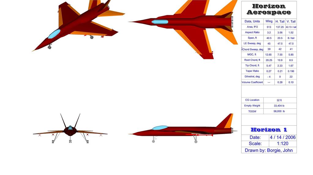
26 the concepts and consideration of the technologies used in each concept. From this ranking method, concept 2 proved to be the preferred concept. Table 3.3: Selection Chart to Determine Final Concept Selection Criteria Weight Concept 1 Concept 2 Concept 3 Size (Length) Weight Cost L/Dmax CLmax (Take Off) CLmax (Landing) CLmax (Turn Rate) Sweep Fuel Storage Capability Total Score Presentation of Final Concept Based upon the table above, Concept 2 (now named Horizon One) proved to be the best concept. This concept is traditional in its looks, but has a wide range of abilities. Although this concept is classical in its design, it gets the job done. The group is excited to use this concept and we think that it will prove to be the best aircraft to meet the RFP requirements. Detailed sizing and constraint analysis for the Horizon One can be seen in the performance chapter, section
27
28 4. Aerodynamics The RFP defines several different constraints that are important from an aerodynamics point of view for the Homeland Defense Interceptor. The aircraft must achieve a maximum Mach number of 2.2 at an altitude of 35,000 feet, the aircraft must loiter for four hours at subsonic speeds and the aircraft must make an 18 /sec instantaneous turn. By looking at these constraints, detailed wave drag analysis was performed while taking area rule under consideration. Also, the sweep angle must be chosen such that it meets the loiter constraint while meeting the supersonic Mach number constraint. The two most important constraints from an aerodynamic point of view are achievement of supersonic Mach number and the ability to loiter for 4 hours. Thus, design efforts were directed towards efficient wing design and streamlining the fuselage to reduce the wave drag. 4.1 Airfoil Selection The airfoil selection process was based on looking at already existing aircraft that closely met the RFP requirements, most importantly the critical Mach number requirement and critical performance requirements. The aircraft must travel at supersonic speed; therefore to reduce the wave drag, the airfoil thickness must be small. The aircraft must also loiter for four hours, thus the airfoil must be thick enough to generate enough lift during that four hour period. Airfoils used in different fighter aircraft that meet the RFP requirements are given in Table
29 Table4.1: Airfoil section and characteristics (Ref 4.1) Aircraft Airfoil Clα Clmax t/c Stall AOA F-15 64A % 11 F-18 65A % 8 N/A 64A % 8 N/A 64A % 10 N/A 65A % 9 N/A 65A % 10 The lift coefficient variation with angle of attack (seen in Figure 4.1) and stall characteristics are computed using Designfoil software. The software does not have very good approximation beyond the stall region, but the lift variation with angle of attack is computed very accurately near the stall region. Figure 4.1: Lift coefficient variation with angle of attack (Ref 4.2) 18
30 Figure 4.2: 65A006 airfoil section Using the lift coefficient and stall angle of attack data for different airfoil from Table 4.1, the airfoil selected for the Homeland Defense Interceptor is an NACA 65A006 (seen in Figure 4.2). This airfoil is symmetric with a thickness to chord ratio of 6% and location of minimum pressure at 0.5c. NACA 64A006.6 has the highest maximum lift coefficient and stall angle of attack but the thickness to chord ratio is 7%, which will lead to high wave drag at supersonic speeds. The NACA 65A005 has a 5% thickness to chord ratio but it has the lowest maximum lift coefficient, causing it not to be an efficient airfoil during subsonic speeds. Therefore, the NACA 65A006 has characteristics in between both the NACA 64A006.6 and the NACA 65A005, and it will be efficient in both of the constraint regions. 19
31 4.2 Sweep analysis The RFP requires the aircraft to go supersonic and loiter for 4 hour; therefore an appropriate sweep angle must be chosen to meet these requirements. To reduce the shock wave formation on the airfoil, the critical Mach number must be high. A lower thickness to chord ratio gives a higher critical Mach number. Figure 4.3 shows the critical Mach number variation with sweep and thickness to chord ratio. Figure 4.3: Critical Mach number variation with thickness to chord ratio and sweep angle The sweep angle chosen for Homeland Defense Interceptor is 45. The corresponding critical Mach number from Figure 4.3 is at a thickness to chord ratio of Figure 4.4 shows the wing planform for homeland defense interceptor. 20
32 Figure 4.4: Shows the wing planform for homeland defense interceptor. 4.3 Drag Wave Drag The drag is one of the most important aerodynamic parameters for this aircraft. The aircraft constraints require the drag to be low enough such that the aircraft achieves supersonic speed i.e. a Mach number of 2.2. Wave drag analysis is performed on the entire configuration of the airplane. Harris wave drag code was used to get the wave drag coefficient at supersonic speeds. The wave drag coefficient variation with Mach number is given in Figure
33 Figure 4.5: Wave drag coefficient variation with Mach number Figure 4.6: Drag over dynamic pressure (D/Q) variation with theta. 22
34 The optimum area distribution for the entire airplane configuration is given in Figure 4.7 below and the optimum 3-D fuselage configuration for low wave drag is shown in Figure 4.8. Figure 4.7: Cross-sectional area distribution Figure 4.8: Optimum 3-D fuselage configuration for low wave drag 23
35 4.3.2 Skin Friction Drag The skin friction drag was computed for the entire configuration using a friction code. The geometric parameters used in the friction code are given in the table below: Table 4.2 Geometric parameters used in the friction code Components S wet L ref t/c or d/l Wing Fuselage Horizontal Tail Vertical Tail Figure 4.9: C D0 variation with Mach number at sea-level Induced Drag The induced drag is computed using following equation: CD i = CL 2 π AR e (1) 24
36 The Oswald efficiency factor is estimated using the LIDRAG code for a span loading given at a particular condition. The span loading is computed using tornado code. Elliptical span loading is assumed to reduce the induced drag. The Oswald efficiency factor is estimated to be The induced drag is computed at takeoff, landing, cruise and for an aircraft traveling at a Mach number of 2.2. Table 4.3 shows the drag coefficient at different flight conditions: Table 4.3: Drag coefficient values at different flight conditions Drag Coefficient Cd0 Cdi Cdw Takeoff Landing Cruise (30000 ft) M = 2.2 (35000 ft) Total Drag The total drag is computed at the different flight conditions shown in Table 4.4. The total drag at takeoff, landing, cruise and Mach 2.2 is given below: Table 4.4: Overall drag at different flight conditions Total Drag Computation Condition Mach number D (lb) Takeoff Landing Cruise M = The contribution of drag coefficient at different flight condition is given by following pie charts: 25

37 Figure 4.10: Drag coefficient contribution at different flight conditions. The overall drag coefficient variation with Mach number is given below: Figure 4.11: Drag coefficient variation with Mach number at sea-level 26
38 Figure 4.12: Shows the supersonic drag polar at M = 2.2. Figure 4.13: Shows the subsonic drag polar at M = (Loiter) 27
39 4.4 High Lift Surfaces To generate lift during takeoff and landing, leading edge flaps and trailing edge flaps are deflected appropriately. Table 4.5 shows the aircraft configuration and aerodynamics characteristics used during takeoff and landing. Figure 4.14 shows the slope of lift coefficient at different leading edge deflection values with variation to Mach number. Figure 4.15 shows the lift coefficient variation with angle of attack at different flap deflection values. The change in lift coefficient at different flap deflections is computed using tornado subsonic code. Table 4.5: Shows the aerodynamics characteristics during takeoff, landing and turn High Lift Devices Takeoff Landing 18 deg/s Turn Angle of Attack (deg) Leading edge Flap Deflection (deg) Trailing edge Flap Deflection (deg) V (ft/s) CL L/D N/A CD N/A Schematic 4.1: Shows the schematic of trailing edge plain flap (Ref 4.3) Schematic 4.2: Shows the schematic of leading edge flap (Ref 4.3) 28
40 Figure 4.14: Leading edge flap slop variation with Mach number (Ref 4.3) Figure 4.15: CL variation with flap deflection 4.5 Wing Characteristics The twist distribution for the homeland defense interceptor is computed by taking the root twist angle to be 5 degrees and the tip twist angle to be -3 degrees. The twist angles were determined by looking at already existing aircraft that met the mission 29
41 structural requirements. The span load distribution is also computed using the trapezoidal wing equation with elliptical span loading. The geometric properties of the wing, horizontal and vertical tail are given in Table 4.6. Figure 4.16: Twist distribution Figure 4.17: Span load distribution at cruise 30
42 Table 4.6: Geometric characteristics of the different lifting surfaces Horizontal Lifting Surfaces Wing Tail Vertical Tail Span /tail Area Aspect Ratio Root Chord Tip Chord Taper Ratio Mean Aerodynamic Chord, MAC Xloc, MAC N/A Yloc,MAC N/A Leading Edge Sweep Quarter Chord Sweep Aerodynamics Conclusions Looking at the constraints, the fixed wing homeland defense interceptor fulfills all the mission requirements. The aircraft has enough thrust at 35,000 feet to overcome drag at Mach number of 2.2. The aircraft also has enough thrust to overcome drag at takeoff and landing. Furthermore, the aircraft generated enough lift using its lifting surfaces and high lift devices to attain shorter takeoff and landing distances. The turn rate constraint is also met by a given amount of lift coefficient generated by the high lift devices. 5. Propulsion 5.1 Project Drivers The AIAA RFP requires a broad range of speeds and altitudes at which the Homeland Defense Interceptor must operate. Its max speed is to be a Mach number of 2.2 at optimum altitude. It must also loiter for four hours at 35,000 feet at a Mach number of approximately 0.9. This requires the engine to not only have high thrust 31
43 capability but also a low subsonic SFC so a huge amount of fuel is not needed to meet the loiter requirement. While this is a requirement from only one mission, if the concept meets the performance required in this mission the remaining two missions will also be met with little or no other modifications to the design of the engine or its components assuming all supersonic dashes are relatively short. The RFP also requires that the engine used for the Homeland Defense Interceptor be an already existing and available engine technology or one that will be available in the near future. 5.2 Engine Specifications Before deciding which engine model was going to be used many existing engines were examined. Some of the engines considered were the GE F101, F110, and the F136. The F110 is the current engine used in the F-14, F-15, and F-16. The F136 is the engine used by the JSF. While most of these engines would probably not meet the missions set forth by the RFP it would also be very difficult to get engine data to perform any sort of calculations. To perform preliminary analysis the GE F-414 turbojet engine was used in mission planning. This is the engine core used in the F/A-18 E/F Super Hornet. The engine deck was provided by the AIAA Request for Proposal for the 2005/06 Undergraduate Design Competition. The engine deck included flight speed, altitude, uninstalled thrust, fuel flow, and power settings. There are ten power settings for the non-afterburning configuration and five power settings for afterburning. The engine has a maximum diameter of 35, a length of 154, 3 fan stages, and 7 compressor stages. It contains one high pressure turbine and one low pressure turbine. There is an overall pressure ratio of 30 and a bypass ratio of
44 There was also a decision to be made about whether to use one or two engines. While it will be very expensive to outfit each HDI with two engines, it was decided that two engines were going to be used for the concept to be submitted for response to the RFP for optimum performance at both design and off design points. 5.3 Preliminary Analysis ACSYNT, a mission planning program was used to examine the performance of the concept with these engines. The program accepted all the parameters given in the engine deck excluding the power setting. It also required a corrected installed thrust which accounted for losses associated with the installation of inlets and nozzles. 5.4 Preliminary Inlet and Nozzle Considerations When the inlet and nozzles are installed there will be a loss of total pressure causing the net thrust to decrease. There is an approach for accounting for these losses in Dan Raymer s Aircraft Design text however this produced unrealistic answers using the uninstalled thrust values from the RFP. The equations for this approach appeared to be derived from empirical results in experiment and could not simply be applied to the engine core being examined. Initially a loss of 10% thrust was used for supersonic flight and 5% for subsonic flight for preliminary analysis. These numbers were obtained from an AIAA report on Analysis of effects of inlet losses on performance of axial-flow type turbojet engines (Ref 5.1). The possible inlets considered to get the air down to an acceptable speed for the engine were spikes and ramps. These both provide for the necessary shocks. While the 33
45 inlet has not been designed at preliminary stages, a spike was determined to be useful for Mach numbers over 2.5. The drag and possible unnecessary spillage associated with a spike is too high for a flight Mach number of 2.2. The preferred geometry concept is a variable geometry ramp. This option will provide the necessary 2-3 shock system to slow the supersonic flow down to a uniform subsonic flow that will be accepted by the engine. However, there are tradeoffs for the money and room needed to install the necessary actuator to move the ramp back and forth to be considered and in this case was not feasible seeing that the HDI will only operate for any amount of time at one supersonic speed. The associated drag and losses associated for the acceleration up to this dash speed will not be worth the money to fix them assuming the time in between the sound barrier and the design supersonic Mach number is relatively short. 5.5 Inlet system design When first approaching what design of inlet will best suit the engines given the three missions stated by the RFP a decision of what type of shock system will be used. While it has already been decided that the geometry of the inlet shall be fixed there are many types of compression techniques to get airflow to a state acceptable to the engine. The first and ultimately the one chosen for this engine and set of missions is an external compression system as shown in the figure below. Figure 5.1: External Compression System Schematic. (Ref 5.2) 34

46 This is the preferred approach for flight speeds under M=2.5. Another system would be a mixed compression system which is normally only suited for flight speeds greater than Mach 2.5 so was not considered. The specific type of inlet chosen will be a wing-shielded design shown below. Figure 5.2 Wing-Shielded Configuration A side mounted configuration was chosen because of enhanced performance in the positive angle of attack region by way of fuselage shielding even during yawed flight on the wind side engine. Not only was the performance of inlet was examined, but flow fields at the entrance to fan are also a very important component. This is the flow at the entrance to the engine must not have any non-uniformities such as total pressure and temperature. These non-uniformities can be encountered from the firing of ordinance or steam from catapult launches (Ref 5.2). The impact of inlet installation will involve the net thrust available to each engine component operating lines, cycle flow adjustments, and engine control modes. Other issues considered when examining flow phenomena are inlet buzz and shock and boundary layer interactions which further complicate the design of the inlet. Using an 35
47 external compression should have a pressure recovery more than 95% at the design Mach number and higher recoveries as Mach number is decreased Inlet system sizing The first area of consideration when determining the size of the inlet is the capture area. This is defined as the area corresponding to the vertical distance between cowl lip and ramp point and the fixed width of the inlet. Looking at it from the front would produce a rectangular cross-section. Other areas to consider are bleeding air and bypassing air. In this case the engine core has a required bypass ratio of From continuity the following equation must be satisfied: A o Engine = Ao Ao Ao (1) Inlet Bleeed Bypass where, W θ k ηr δ Engine = * W θ A δa Ao Ao Engine * (2) (* is the quantity at MACH=1.0) The other area contributions in Equation (1) are determined with Equation (2) W θ with the appropriate airflow in place of δ Engine. After the inlet is designed and tested the distortion and recovery characteristics must be checked against the desired operational values. If the inlet mass flow is too high then the inlet area must be increased. On the other hand if the minimum flow rate is less than the sub critical 36

48 stability limit the inlet should be decreased in area or engine airflow redesigned higher. This would also eliminate inlet buzz. Spillage drag is established over the range of operating MACH numbers, MFR s, and incidence angles. Spillage drag would be zero at an MFR=1. Most likely this critical inlet limit will not be reached with this inlet geometry. While airflow to the engine and cycle matching for optimum thrust or SFC establish inlet characteristics, spillage drag is examined to optimized installed performance. The total inlet drag can be attributed to the friction and pressure drag of the upper and lower cowl and the side plates. A basic drawing of a typical GE engine installed is shown below. Figure 5.3: Drawing of inlets and engine Equation 3 was used to calculate the inlet area. This equation was used to calculate A/A* at the inlet face where the design Mach number is 2.2 and at the engine face where the Mach number is 0.4. Once these two values were found they were divided 37
49 into each other to eliminate the critical area and the ratio of inlet area to engine face area was found to be 1.26 giving an inlet area of 8.42 ft 2. A A = * 1 M 2 γ 1 1+ M γ γ + 1 ( γ 1) 2 (3) 5.6 Exhaust System To design the nozzle a convergent-divergent nozzle was used to accelerate the flow out of the engine with a design Mach number of 2.2. The exhaust was taken to be perfectly expanded so that the back pressure was equal to that of the surrounding atmosphere. With this condition the throat area was found as well as the exit area and Mach number. Since this is a perfectly expanded case the critical area is equal to the throat area. The throat area was found to be ft 2. From this an exit Mach number was found to be 2.87 and the exit area was found to be ft Final Design Two F-414 engines will be used in this design. Table 5.1 shows the final dimensions and characteristics of the selected engines. Table 5.1: Final Engine Characteristics SLST lbs SFC 1.5 Diameter 35" Weight 3000 lbs Length 154" Inlet Area ft 2 Exit Area ft 2 38
50 5.8 Engine Removal To minimize time and effort required to maintain each aircraft engine, the engine pods must be easily removable. The design for this aircraft is a bottom removal configuration needing only a lifting cart to move lower and move the engine. This configuration was chosen over a rear removal configuration because of it lower the chance of the engine damaging other components of the aircraft during removal. Figure 5.4 displays the removal of the engine. Figure 5.5 is a view of the flaps rotated down to allow the engines to be removed. Figure 5.4: The Engine Removal Diagram Figure 5.5: View from the rear of the aircraft 39
51 6. Stability and Control 6.1 Method of Analysis There are four flight conditions chosen to perform stability and control analysis on the Horizon One in accordance with the requirements of mission 1: Loiter (LR), a 360º turn at Mach 1.2 (TR1), a 360º turn at Mach 0.9 (TR2), Maximum Mach (MM), and Low Speed (LS). The longitudinal and lateral derivatives were obtained using Digital DATCOM and Tornado, a Vortex Lattice Program. The design and analysis of the stability augmentation system (SAS) was done using the methods described in Nelson (Ref 6.1). The dynamic stability and SAS were analyzed using a program written in Matlab and Simulink. The lateral derivatives of the Horizon One at supersonic speeds were unobtainable using Digital DATCOM and Tornado. The lateral derivatives at supersonic speeds can be obtained using Computational Fluid Analysis programs (CFD). 6.2 Static Stability The required static margin as listed in RFP is ±10 %. The Horizon One is selected to have marginal stability. The static margin with fixed CG location and moving aerodynamic center with changing Mach number is shown in Figure 6.1. The relaxed static margin was chosen due to the benefits of lower trim drag and higher maneuverability at transonic and supersonic speeds. The location of the aerodynamic center of the Horizon One was estimated using the methods described in the Digital DATCOM. 40
52 Figure 6.1: Static Margin with fixed center of gravity with varying Mach Number. The negative static margin resulted in the unfavorable open loop longitudinal dynamics. The appropriate MIL specifications for longitudinal dynamic characteristics of the Horizon One were met by employing SAS. The Horizon One employs a digital flyby-wire system to meet the performance requirement and to improve ride quality. The RFP requires the static of margin to be with in ±10 %. Figure 6.1 shows that the static margin is nearly 15% at supersonic speed. 6.3 Control Surface Concept Selection and Sizing The Horizon One deflects an all moving horizontal tail symmetrically to generate pitching moment. The all moving horizontal tail is found to be necessary to generate pitching moment in transonic and supersonic regions. The Horizon One is equipped with 41
53 flaperons which act as flaps when deflected symmetrically during take off and landing, and act as aileron when deflected asymmetrically to generate the rolling moment. The yawing moment on the Horizon One is generated by symmetrically deflecting the rudders on the twin vertical tails. The symmetric deflection of flaperons and asymmetric deflection of the rudder on the twin vertical tail produces a speed break system. The horizontal tail was sized to meet the take off rotation requirement. The rotation requirement is based on take off distance and take off speed of Mach 2.4. Figure 6.2 The time to rotate 15 degrees about landing gear at various elevator deflection angles 42
54 6.4 Open Loop Dynamic Stability Characteristics M =0.5, Unstable Pole M =0.5, Stable M =2.2, Stable Complex Conjugant Poles too stable Figure 6.3: The poles of the longitudinal aircraft dynamics axes at two Mach numbers at 10,000 ft. The root locus diagram in Figure 6.3 shows that the longitudinal dynamics have an unstable mode at Mach 0.5. The time to the half amplitude for the unstable mode is 0.16 seconds. This mode is highly unstable and is uncontrollable by the pilot. This mode is stabilized by negative feedback of angle of attack. The angle of attack feedback stabilizes the mode but does not meet the flying qualities, thus additional damping is added to the dynamics by utilizing pitch rate feedback. This allows placing the poles of the short period dynamics at desired locations thus meeting the handling qualities. Also, 43
55 the aircraft has highly damped modes at Mach 2.2 therefore positive feedback of alpha is provided to meet the appropriate MIL SPEC Longitudinal SAS The elevator control law for the Horizon One was designed to stabilize the aircraft at low speeds and improve dynamic characteristics at high speeds. The pole placement method as described in Nelson (Ref 6.1) was used to meet the short period characteristics of the aircraft as described in appropriate MIL specifications. The general layout of the longitudinal SAS is shown in Figure 6.4. The gains for the elevator control laws are shown in Table 6.1. Axes joyinput Buttons Point of View Pilot Input Saturation Limits of Elevator 10 s+10 Elevator Actuator Dynamics Alpha Elev ator Input Pitch_rate Scope Longitudinal Dynamics -K- Autopilot Inner Loop - Stabilizing Angle of Attack -K- Pitch_rate 1 s Pitch angle 0 Pitch_rate Feedback Redundancy K(3) theta_de Outer Loop - Autopilot Figure 6.4: The Longitudinal Stability Augmentation System. 44
56 Table 6.1: The Longitudinal Stability Augmentation System Gain Schedule. (LS) M =0.5 4 hr- LR M= 0.85 (TR1) M = 0.9 (TR2) M = 1.2 (MM) M =2.2 SP-ζ SP-ω n rad/s rad/s rad/s rad/s rad/s K α K θ K q The Redundant Pitch SAS The Horizon One is equipped with redundant pitch SAS incase of multiple sensor failures of alpha. The main longitudinal SAS requires the feedback of the alpha and pitch rate sensors which makes the aircraft vulnerable to the sensor failure. The back up pitch SAS system comes online if it detects multiple alpha sensor failure scenarios. The pitch back feedback redundancy gain is added to the system to overall increase the feedback gain to stabilize the aircraft over the entire flight region but can not meet handling qualities. The redundant pitch SAS allows the pilot to safely land the Horizon One. The redundant pitch SAS operates on independent rate gyro. 45
57 6.4.3 Lateral SAS The lateral SAS includes the control laws for the aileron and rudder. The lateral SAS is utilizes angular rates measurements from the gyros to stabilize the Dutch roll modes of the aircraft. The controls laws for the supersonic flight condition can be obtained since lateral derivatives were not available. The schematic for the lateral SAS is shown in Figure 6.5. The lateral flying qualities are met by meeting the Cooper Harper flying qualities rating. Axes joyinput Buttons Switch Automated Roll Damping Point of View Joystick Input 10 Roll_rate 1 s s+10 Aileron Saturation Aileron Actuator dr da Sideslipe_angle Dynamics Rudder Saturaion 10 s+10 Rudder Actuator Dynamics Sideslipe_rate Aircraft Lateral Dynamics -K- Roll_damping -K- Gain1 Bank_angle Sideslipe_angle In1 Out1 In2 Sideslipe_Suppression Sideslip suppression Figure 6.5: Lateral Stability Augmentation System. The closed loop lateral dynamic characteristics of the Horizon One are shown in Table
58 Table 6.2: The Lateral Flying Qualities Dutch Roll: ζ dr ω ndr Roll Mode: Time Constant Spiral Mode: T half Cycle rad/s ~1.04 sec sec 6.5 Banking Performance The roll performance requirements for air to air combat are satisfied according to MID STD The performance requirement requires the bank angle to increase 90 degrees in one second thus requiring high aileron authority. The aileron had inherited high authority due to low roll damping and large size. But, this resulted in high time Figure 6.6: Aileron Response 47
59 constant for the roll mode. Thus, a switch was placed in control system which activated feedback gain when there was no pilot input and deactivated when there was a pilot input to allow high aileron authority. The required gain schedule for roll performance requirement and Dutch roll damping are shown in Table 6.3. Table 6.3: Lateral Stability Augmentation System Gain Schedule 48
60 49
61 7. Performance 7.1 Constraint Analysis Constraint analysis is the method to analyze the weight, thrust, and wing area at the same time to get the optimum performance during specific mission conditions. The thrust to weight and wing loading plot were analyzed to obtain the design point. The take-off, landing, stall and cruise constraints are plotted for thrust to weight and wing loading. The following constraints are used to obtain the design point: The maximum Mach number of 2.2 must be satisfied. The structure should withstand the load factor of +7 and -3. The maximum instantaneous turn rate of 18 degree per second must be satisfied. The aircraft must clear 50 feet obstacle during takeoff. The aircraft must sustain the 360 degree turn at Mach Theory power. The constraint analysis theory is derived using energy balance using specific excess P s [ Pava Preq ] [( T D)] = = W W Other relationships used to analyze the constraints on the aircraft are the static rate of climb. The equation for static rate of climb is: (1) dh [ ] dt static [( T D) V ] = W (2) 50
62 A more general relationship for specific excess power is given as: [ P P = P W ] [( T D)] dh = = [ ] W dt avai req s + V dv ( )( ) g dt (3) The specific excess power relationship shows the excess engine power can be used to increase the aircraft s potential energy (climb) or its kinetic energy (speed). The power required is the power needed to cruise at a straight and level condition, to overcome drag and to go fast enough to give enough lift to equal the weight. If engine is capable of producing more power than the power required, that power can be used to make the aircraft accelerate to a faster speed or to climb to a higher altitude or, to give the aircraft more maneuverability. Using equations (1) (2) and (3) the following equation can be derived, which is in terms of the constraint parameters T/W and W/S. T ( ) V W D = ( ) V W + dh dt V + g dv dt The general drag relationship is used to get the lift coefficient in the constraint analysis equation. The drag relationship is given as: (4) 2 1 D = ( CD + KCL ) ρv S (5) 51
63 Using the drag equation and substituting in equation (4), more general form of the equation is derived for thrust to weight and wing loading. The general form of the equation is given as: 2 T ( qcd ) Kn W 1 dh 1 dv = 0 + ( )( ) + ( ) W W / S q S V dt + g dt q = 1 2 ρ V 2 L C L = = qs Equation (4) is a very general performance equation that can deal with changes in both speed and altitude and changes are the function of the thrust to weight T/W and wing loading W/S. nw qs (6) Calculations and Analysis Straight and Level cruise Constraint Using the general form of the constraint equation (6), the straight and level flight constraint is derived. The following condition for straight and level flight is used to simplify equation (6): For Straight and Level flight, n = 1 and: dh dt dv dt = 0 = 0 The following equation can be used for straight and level constraint: 52
64 T qcd 0 K W = ( ) + ( )( ) W W / S q S (7) The drag coefficient is estimated to be 0.02, Mach number = 2.2 and dynamic pressure is computed using velocity and density at feet Stall Constraint The stall constraint is computed using the maximum lift coefficient and velocity at stall. The maximum lift coefficient is estimated to be 2.0 for our fighter aircraft. The velocity at the stall condition is estimated using CLmax. The constraint equation for stall condition in terms of wing loading is: W S = ρv stall C L max (8) Climb Constraint The climb constraint is derived using equation (6) with constant velocity. Using constant velocity, the following equation is derived: The climb rate is estimated to be: dh ft = dt min T 2 ( qc Kn W dh D 0 ) 1 = + ( )( ) + ( W W / S q S V ) dt (9) 53
65 Takeoff Constraint The takeoff constraint equation is derived using the takeoff distance equation, which depends on the drag coefficient to ground friction drag. S TO = 1 A )ln[ 2 * B A BV ( 2 TO ] T A = g[( 0 ) μ] W g B = ( )[ 1 ρ S( C C ) a ] 2 D μ Lg + W μ C Lg = 2K T = T 0 a V 2 (10) Using equation (10), the following equation is used to compute the takeoff constraint: W S = ( TOP)σC LTO T W ρalt σ = ρ sl The takeoff parameter is estimated using a given chart for takeoff parameter and takeoff distance. (11) Results and Discussion A Matlab subroutine was used to compute the constraint analysis, which uses constraint theory and derived equations to plot the thrust to weight and wing loading graphs. 54
66 The subroutine requires the user to input the wing span, wing area, Mach number and weight. Using the subroutine for the Horizon One, the following constraint graph is generated for all the above mentioned constraints Constraint Analysis Graphs Cruise Climb Take Off Stall T/W T/W = 1.25 W/S = 95 Design Point W/S (lb/ft 2 ) Figure7.1: Constraint analysis plot. The design point is at T/W = 1.25 and W/S = 95 A thrust to weight ratio of 0.6 and below is not feasible because it does not meet the climb requirement. A wing loading of below 30.4 lb/ft 2 is not possible because of the stall constraint. When sizing the wing, it had to be made certain that the stall wing loading was low enough to achieve the 18 /sec turn rate constraint. The large wing area of 519 ft 2 is used to achieve this along with creating a large area for fuel to be stored during the 4 hour loiter. 55
67 7.2 Maximum Mach number requirement The AIAA RFP requires that the HDI be able to accelerate to M = 2.2 at ft. To accomplish this, thrust must overcome drag at the prescribed altitude. With the power plants selected on this aircraft, the thrust at ft is lbs. This must be greater than the drag at the given altitude determined from the equation (Ref 7.1): D = 0.5C D0 ρ V 2 S + 2KW ρsv 2 2 Figure 7.2 shows the comparison of the thrust to drag (1) 30,000 28,000 26,000 Thrust at ft = lbs Thrust / Drag (lbs) 24,000 22,000 20,000 18,000 Drag at ft = lbs 16, Mach Number Figure 7.2: Thrust to Drag Comparison for Max Mach number constraint 56
68 There is a large margin between the thrust and drag lines at the M = 2.2 and at an altitude of 35000ft. The thrust is greater than the drag of lbs at this altitude. This is well away from the transonic region where drag has a sharp increase so the aircraft is capable of achieving the required speed. 7.3 Maximum Thrust Specific Excess Power Envelope The RFP requests a 1-g and 5-g specific excess power envelopes for our aircraft along with the more specific requirements seen in Attachment 4 of the RFP. At maximum thrust, the aircraft must have a 1-g specific excess power of 700 ft/s at sea level and Mach 0.9 and 400 ft/s at ft and the same speed. At 5-g S.E.P, the numbers decrease to 300 ft/s at sea level and Mach 0.9 and 50 ft/s at ft and the same speed. The 1-g specific excess power contour plot of the design at 50% internal fuel is shown in Figure 7.3. This design s 1-g specific excess power is shown to be 500 ft/s at sea level and greater than 400 ft/s at ft while traveling Mach 0.9. The ft requirement is met while the sea level specific excess power is not. This figure is created from data provided by ACYSNT, and at this time, the engine deck is not functioning properly. The default engine deck of a TF-30 is being used explaining the missing requirement. 57
69 1 - G Specific Excess Power h (ft) M Ps = 200 Ps = 300 Ps = 400 Ps = 500 Ps = 600 Figure 7.3: 1 g Specific Excess Power Envelope The 5-g specific excess power contour plot of the design is shown in Figure
70 5-G Specific Excess Power Envelope h (ft) M Ps = 100 Ps = 200 Ps = 300 Ps = 400 Ps = 500 Figure 7.4: 5-g Specific Excess Power Envelope 7.4 Max Thrust Sustained Load factor The RFP also requires a maximum thrust sustained load factor envelope to see if the design is capable of performing the requirements of Attachment 4. At maximum thrust, the aircraft must be able to sustain a load factor of 5.0 g s at Mach 0.9 and at an altitude of ft. The sustained load factor envelope at 50% internal fuel is shown in Figure 7.5. The orange line represents the envelope at ft, and at Mach 0.9, the sustained load factor is 5.0 g s. This meets the RFP requirement. 59
71 Max Thrust Sustained Load Factor Envelope Nz k 15k 20k 30k 40k 50k M Figure 7.5: Maximum Thrust Sustained Load Factor Envelope at 50% internal fuel weight 60
72 Table 7.1: A comparison of the RFP requirements to our design s capabilities Minimum Requirement Value Our Ability 1-g Specific Excess Power Military Thrust 0.9 M / Sea Level 0.9 M / 15,000 ft 200 ft/s 50 ft/s ft/s ft/s 1-g Specific Excess Power Maximum Thrust 0.9 M / Sea Level 0.9 M / 15,000 ft 700 ft/s 400 ft/s 1051 ft/s 727 ft/s 5-g Specific Excess Power Maximum Thrust 0.9 M / Sea Level 0.9 M / 15,000 ft 300 ft/s 50 ft/s 400 ft/s 300 ft/s Sustained Load Factor Max Thrust 0.9 M / 15,000 ft 5.0 g s 5.0 g s 7.5 Instantaneous Turn Rate Requirement The AIAA RFP requires the Homeland Defense Interceptor be able to generate an 18 /sec instantaneous turn rate at ft. This is one of the more difficult constraints to meet and a key driver in the sizing of the design. The instantaneous turn rate is a function of velocity and load factor. This instantaneous turn rate also helps to size the wing because it also depends on the wing loading and maximum lift coefficient. The equations explaining these are seen below (Ref 7.2): 61
73 = ψ g V n 2 1 (2) W S = qc L max n (3) Originally the aircraft was designed with a load factor of 7 and a CLmax of This combination led to a velocity 710 ft/s at 18 /sec. Originally, the wing did not create enough lift at this speed. The structural properties of the wing were changed to be able to withstand a load factor of 9 g s. Also the aerodynamics of the wing were changed to be able to achieve a CLmax of 2.0 by using high lift devices such as leading and trailing edge flaps. With these new properties, the speed in the turn increases to ft/s. This also gives a reasonable value for wing loading of 69 lb/ft2. Figure 7.6 shows how the aircraft meets the requirement. 62
74 20 n = n= n=4 turnrate (deg/s) 10 8 n=2 W/S = CLmax = velocity (fs/s) Figure 7.6: Instantaneous Turn Rate requirement met at a load factor of 9 and C Lmax = 2 The drag is much greater than thrust developed at ft; therefore the aircraft would not be able to maintain a constant altitude and speed in the 18 /sec turn while performing the maneuver. It becomes a descending turn which is not a problem because the RFP requires the 18 /sec turn only be instantaneous. 7.6 Mission Analysis Preliminary mission analysis for each mission can be seen in Tables 7.2 through 7.4 below. The primary focus of this analysis was determining how much fuel was consumed during each mission leg, in particular the fuel consumed during loiter in the defense counterair patrol mission. All mission analysis was performed using ACSYNT. 63
75 Table 7.2: Mission analysis for Defense Counter-Air Patrol Mission Table 7.3: Mission Analysis for Point Defense Intercept Mission 64
76 Table 7.4: Mission Analysis for Intercept/Escort Mission 8. Materials and Structures 8.1 Materials When choosing materials for this type of aircraft, one must consider many different factors. First and foremost, cost of the material plays a major role in the selection process. The RFP requires a low cost aircraft, and with an aircraft as large as ours, the team could not afford to cover the aircraft completely with pricey composites or titanium. Therefore, composites and titanium are used sparingly in locations such as control surfaces or engine connections. Weight also plays a large role in the selection process, so the team chose lightweight aluminums for the structural components as well as an aluminum composite for the skin of the fuselage and the tail. A new material, Ferrium S53 was chosen for the landing gear, due to its unique ability to resist wear and tear while maximizing strength and toughness (Ref 8.1). Aluminum has always been a popular material in aircraft construction due to its resistance to corrosion and its ability to be easily machined with a wide variety of surface 65
77 finishes (Ref 8.2). Aluminum s strength also increases at lower temperatures, making it a perfect material to use for aerospace applications due to the low temperatures at which most aircraft operate (Ref 8.2). Aluminum also comes with a low price tag, which made it attractive to our group. Knowing that our aircraft was going to be large, we needed to find a material that would satisfy all of our needs, but be low cost. AL7075-T6 was chosen for the wing skin. AL 7075-T6 was first introduced in the industry in 1943 and has been used in most aircraft ever since (Ref 8.3). The bulkheads are to be constructed of AL 2024-T3 and an aluminum-lithium alloy (AL 2091) was chosen for the majority of the structural components. Aluminum-lithium was chosen for the structure with weight in mind. These alloys were first developed as a low weight material to replace existing aluminum alloys (Ref 8.4). Just because the material is low weight, does not mean it lacks in fatigue strength or toughness. In fact, Al-Li alloys have fairly low densities, good fatigue strength and toughness, a high elastic modulus, and excellent fatigue crack growth resistance, making this an excellent choice for structural applications (Ref 8.4). Glare was chosen to cover the entire fuselage, as well as the horizontal and vertical tails. This fairly new material is made up of alternating layers of aluminum and glass and epoxy adhesive (Ref 8.5). The main advantage of Glare is its weight, a main reason why it was chosen for our aircraft. Glare can weight anywhere form 15 to 30 percent less than AL 2024-T3, and since it is used to cover the entire fuselage, it greatly reduces the total weight of our aircraft (Ref 8.5). Weight isn t the only thing that this material has going for it. Glare also boasts fire resistance, increased impact performance, and decreased crack propagation and corrosion. It can also be repaired just as easily as regular aluminum alloys (Ref 8.5). The only slight drawback is its cost; however, it is only slightly more expensive than 66
78 standard aluminum alloys and about the same price as advanced aluminum composites (Ref 8.5). When it comes to composites, most aircraft use some sort of a carbon fiber composite for control surface applications. Our group chose a carbon fiber/epoxy for all of the control surfaces on the aircraft. Carbon fiber composites have proven to be very effective in resisting high fatigue and corrosion, making them perfect for control surfaces that experience high loading. Ti-6Al-4V was chosen for all of the engine connectors due to its ability to resist high temperatures and corrosion. Ti-6Al-4V is an alpha-beta titanium alloy, the most commonly used titanium alloy in the aerospace industry. Titanium is also very low weight, another plus for our team. A new material, Ferrium S53 was chosen for the landing gear structure. Developed by QuesTek Innovations, LLC, Ferrium S53 is a high strength steel with material properties similar to conventional high strength steels, but with a much higher resistance to corrosion (Ref 8.1). This resistance to corrosion makes it ideal for use in landing gear applications, an area where high fatigue and high loadings are very common. A basic material properties for each material discussed above can be seen below in Table 8-1. This table lists density, ultimate tensile strength, ultimate yield strength, and elastic modulus for each material. Limited data was available for newer materials, such as Ferrium S53 and Glare. The location of each material is listed in Table 8.2 and shown visually in Figure
79 AL 2024-T3 AL 2091 Table 8.1: Material Properties AL 7075-T6 Carbon Fiber Epoxy Ferrium S53 GLARE Ti-6Al- 4V Density (lb/in 3 ) Tensile Strength, Ultimate (psi) Tensile Strength, Yield * (psi) E (ksi) * * The values for the carbon fiber epoxy are the flexural yield strength and the flexural modulus Limited data was found for GLARE and Ferrium S53 due to the fact that they are fairly new materials and material data is not readily available for them. Table 8.2: Material Placement Material AL 2024-T3 AL 2091 AL 7075-T6 Carbon Fiber Epoxy Ferrium S53 GLARE Ti-6Al-4V Location Bulkheads Wing spars, ribs, tail structure Wing skin All control surfaces Landing gear Fuselage skin, horizontal and vertical tail skin All engine connections 68

80 Figure 8.1: Material Placement 8.2 Structures V-n Diagram The V-n diagram for the chosen concept is shown in Figure 8.2. The ultimate loads stated by the RFP were +7/-3 g s and were divided by a factor of safety of 1.5 to get the limit load factors for the structural flight envelope. The analysis used sea level equivalent airspeed so that the flight envelope could be assessed at any altitude. The cruise speed was taken to be 949 m/s. The dive speed was then assumed to be 3 times the cruise speed which equated to a speed of 2847 m/s. The positive and negative maneuvering lines were based on a 69
81 C znmax = 1.40 and C znmin = The gust lines, which are shown in red, are based on the standard gust velocities of 66 ft/s for max gust, 50 ft/s for cruise gust, and 25 ft/s for dive gust. These gusts lie do not limit the maneuvering diagram Figure 8.2: V-n diagram showing load factor as a function of airspeed Fuselage Structure The fuselage will be supported by a system of frames, longerons, stringers, and pressure bulkheads. The pressure bulkheads will enclose the cockpit and also support the nose and main landing gear. Stringers will be placed 12 apart around the cross-section of the fuselage. Frames will be spaced 24 apart except in areas that carry large loads such as at wing spars, tail spars, landing gear housing, and engine mounts. A diagram of the fuselage structural concept is shown below in Figure

82 Figure 8.3: Fuselage support structure Wing Structure To carry the loads in the wing there will be a system of spars and ribs. Due to a low aspect ratio wing there will a larger number of spars than ribs which is also the current trend in American fighter aircraft. There will be 8 spars spaced every 7% of the chord until 56% to allow room for actuators. There will also be five ribs. These ribs will not only provide support for aerodynamic loads but also a place to mount weapons. These ribs will provide the needed support when missiles are being fired. Figure 8.4 shows a diagram of the wing support structure. 71


83 Figure 8.4: Wing support structure 8.3 Landing Gear The nose and main landing gear of the Horizon One are modeled after those of the F- 16. The idea behind the design was to keep it as simple as possible. The nose gear, shown in Figure 8.5, is a double wheel design. Figure 8.5: Nose Gear The nose gear retracts backwards and rotates 90 degrees during take-off to fit horizontally within the wheel bay. The main gear, shown in Figure 8.6 retract forward into wheel bays. 72

 Max Static Nose Gear Load Min Static Nose Gear Load Max Braking Nose Gear Load Tail Scrape Angle 26397 lbs. 10232 lbs.")
84 Figure 8.6: Main Gear Both the nose and main gear are operated using hydraulics. A pneumatic blow-down backup system is also included in the event of a hydraulic system failure. Landing gear specifications can be found in Table 8.3 below. Calculations were made using steps found in Currey s Aircraft Landing Gear Design: Principles and Practices (Ref. 8.6). Table 8.3: Landing Gear Specifications Max Static Main Gear Load (per strut) Max Static Nose Gear Load Min Static Nose Gear Load Max Braking Nose Gear Load Tail Scrape Angle lbs lbs lbs lbs degrees Tire specifications are found in Table 8.4 below. Table 8.4: Tire Specifications Main Gear Nose Gear Wheels per strut 1 2 Tire Size (in.) 19.0 X X 5.5 Tire Pressure (psi)
85 9. Systems 9.1 The Cockpit Layout The cockpit layout must account for comfort of the pilot, ability for the pilot to safely enter and exit on ground and during ejection, and minimize space usage to allow more room for systems, fuel and other items. The designed cockpit layout is presented in Figure 9.1 below. Figure 9.1: The Cockpit Layout This concept was designed to encompass the Air Force cockpit clearance dimensions specified in Nathan Kirschbaum (Ref 9.1). The downward nose clearance angle is 14, and the blind spot is 7 giving ample view for the pilot. The canopy opening gives the pilot 28 inches of opening where only 20 inches is required. Specifically, the canopy opening is an aft hinged configuration, that angles back an estimated
86 9.2 The Cockpit Instrument Panel The instrument panel for this aircraft was adapted from the F 16 configuration. This is first and most recognizable by the two large multiple function displays on either side of the center most console. A third, smaller multiple function display screen is added adjacent to the integrated control panel for the pilot s use. These multiple function displays allow the pilot to see information most needed by the pilot. The center of the instrument panel includes the basic instruments for flight. The airspeed indicator, altimeter, vertical direction and horizontal situation indicators headline the center. The rate of climb and angle of attack indicators also appear here. In addition, the warning lights are located just below the integrated control panel. These warning lights are the most serious warning indicators. Therefore, they are placed directly in front of the pilot for clear view. Another key feature of this design is the extra movement room surrounding the control stick. It is clear that the pilot must have ample room to maneuver the stick during flight. This was a key factor in the instrument panel design. A full diagram of the aircraft instrument panel follows in Figure
87 Figure 9.2: The Instrument Panel 76
88 The following list gives the number and name of each portion of the instrument panel as seen above in Figure HUD 2. Integrated Control Panel 3. Warning Lights 4. Airspeed Indicator 5. Altimeter 6. Angle of Attack Indicator 7. Altitude Direction Indicator 8. Rate of Climb Indicator 9. Horizontal Situation Indicator 10. Instrument Mode Panel 11. Fuel Quality Selector 12. Armament Control Panel 13. Data Entry Display 14. Fuel Flow Indicator 15. G Force Indicator 16. Compass 17. Multiple Function Display 18. Multiple Function Display 19. Rudder Pedal 20. Rudder Pedal 21. Multiple Function Display 22. Radar Display 23. Threat Warning Panel 24. Engine RPM Indicator 25. Fuel Quantity Indicator 26. Nozzle Position Indicator 27. Fan Inlet Temperature Indicator 28. Landing Gear Panel 29. Landing Gear Controls 30. Fuel Control 31. Ignition Panel 32. Speed Brake 33. Throttle Stick 34. Electronic Panel 35. Manuel Pitch Override 36. Radio Control Panel 37. Emergency Power Panel 38. Audio Panel 39. Canopy Jettison 40. Chaff Flare Panel 41. Manuel Canopy Control 42. Exterior Lighting 43. Aux. Comm. Panel 44. Flight Control Panel 45. Manuel Trim Control 48. Oil Pressure Indicator 49. Emergency Power Display 50. Fault Display 51. Hydraulic Pressure Display 52. Caution Panel 53. Cabin Pressure Indicator 54. Oxygen Quantity Indicator 55. Analog Clock 56. Sensor Power Management Panel 57. HUD Control Panel 58. Interior Lighting Panel 59. Air Condition Panel 60. Data Transfer unit 61. Oxygen Regulator Panel 62. Avionics Power Panel 63. Anti Ice / Antenna Selector Panel 64. Oxygen 65. Test Control Panel 66. Control Stick 77
89
AE 451 Aeronautical Engineering Design Final Examination. Instructor: Prof. Dr. Serkan ÖZGEN Date:
 Instructor: Prof. Dr. Serkan ÖZGEN Date: 11.01.2012 1. a) (8 pts) In what aspects an instantaneous turn performance is different from sustained turn? b) (8 pts) A low wing loading will always increase
The Airplane That Could!
 The Airplane That Could! Critical Design Review December 6 th, 2008 Haoyun Fu Suzanne Lessack Andrew McArthur Nicholas Rooney Jin Yan Yang Yang Agenda Criteria Preliminary Designs Down Selection Features
General Dynamics F-16 Fighting Falcon
 General Dynamics F-16 Fighting Falcon http://www.globalsecurity.org/military/systems/aircraft/images/f-16c-19990601-f-0073c-007.jpg Adam Entsminger David Gallagher Will Graf AOE 4124 4/21/04 1 Outline
Appenidix E: Freewing MAE UAV analysis
 Appenidix E: Freewing MAE UAV analysis The vehicle summary is presented in the form of plots and descriptive text. Two alternative mission altitudes were analyzed and both meet the desired mission duration.
AE 451 Aeronautical Engineering Design I Estimation of Critical Performance Parameters. Prof. Dr. Serkan Özgen Dept. Aerospace Engineering Fall 2015
 AE 451 Aeronautical Engineering Design I Estimation of Critical Performance Parameters Prof. Dr. Serkan Özgen Dept. Aerospace Engineering Fall 2015 Airfoil selection The airfoil effects the cruise speed,
Design Considerations for Stability: Civil Aircraft
 Design Considerations for Stability: Civil Aircraft From the discussion on aircraft behavior in a small disturbance, it is clear that both aircraft geometry and mass distribution are important in the design
AE 452 Aeronautical Engineering Design II Installed Engine Performance. Prof. Dr. Serkan Özgen Dept. Aerospace Engineering March 2016
 AE 452 Aeronautical Engineering Design II Installed Engine Performance Prof. Dr. Serkan Özgen Dept. Aerospace Engineering March 2016 Propulsion 2 Propulsion F = ma = m V = ρv o S V V o ; thrust, P t =
Aircraft Design Conceptual Design
 Université de Liège Département d Aérospatiale et de Mécanique Aircraft Design Conceptual Design Ludovic Noels Computational & Multiscale Mechanics of Materials CM3 http://www.ltas-cm3.ulg.ac.be/ Chemin
AERONAUTICAL ENGINEERING
 AERONAUTICAL ENGINEERING SHIBIN MOHAMED Asst. Professor Dept. of Mechanical Engineering Al Ameen Engineering College Al- Ameen Engg. College 1 Aerodynamics-Basics These fundamental basics first must be
In this lecture... Fixed and variable geometry nozzles Functions of nozzles Thrust vector control Thrust reversal Noise control
 1 In this lecture... Nozzle: Fixed and variable geometry nozzles Functions of nozzles Thrust vector control Thrust reversal Noise control 2 Exhaust nozzles Nozzles form the exhaust system of gas turbine
Classical Aircraft Sizing I
 Classical Aircraft Sizing I W. H. Mason from Sandusky, Northrop slide 1 Which is 1 st? You need to have a concept in mind to start The concept will be reflected in the sizing by the choice of a few key
AIRCRAFT DESIGN SUBSONIC JET TRANSPORT
 AIRCRAFT DESIGN SUBSONIC JET TRANSPORT Analyzed by: Jin Mok Professor: Dr. R.H. Liebeck Date: June 6, 2014 1 Abstract The purpose of this report is to design the results of a given specification and to
AE 451 Aeronautical Engineering Design I Propulsion and Fuel System Integration. Prof. Dr. Serkan Özgen Dept. Aerospace Engineering December 2017
 AE 451 Aeronautical Engineering Design I Propulsion and Fuel System Integration Prof. Dr. Serkan Özgen Dept. Aerospace Engineering December 2017 Propulsion system options 2 Propulsion system options 3
Preface. Acknowledgments. List of Tables. Nomenclature: organizations. Nomenclature: acronyms. Nomenclature: main symbols. Nomenclature: Greek symbols
 Contents Preface Acknowledgments List of Tables Nomenclature: organizations Nomenclature: acronyms Nomenclature: main symbols Nomenclature: Greek symbols Nomenclature: subscripts/superscripts Supplements
XIV.C. Flight Principles Engine Inoperative
 XIV.C. Flight Principles Engine Inoperative References: FAA-H-8083-3; POH/AFM Objectives The student should develop knowledge of the elements related to single engine operation. Key Elements Elements Schedule
The Sonic Cruiser A Concept Analysis
 International Symposium "Aviation Technologies of the XXI Century: New Aircraft Concepts and Flight Simulation", 7-8 May 2002 Aviation Salon ILA-2002, Berlin The Sonic Cruiser A Concept Analysis Dr. Martin
High aspect ratio for high endurance. Mechanical simplicity. Low empty weight. STOVL or STOL capability. And for the propulsion system:
 Idealized tilt-thrust (U) All of the UAV options that we've been able to analyze suffer from some deficiency. A diesel, fixed-wing UAV could possibly satisfy the range and endurance objectives, but integration
In this lecture... Prof. Bhaskar Roy, Prof. A M Pradeep, Department of Aerospace, IIT Bombay
 1 In this lecture... Intakes for powerplant Transport aircraft Military aircraft 2 Intakes Air intakes form the first component of all air breathing propulsion systems. The word Intake is normally used
Dragon Eye. Jessica Walker Rich Stark Brian Squires. AOE 4124 Configuration Aerodynamics
 Dragon Eye Jessica Walker Rich Stark Brian Squires Outline Purpose/Mission Air Vehicle Configuration Airfoil Data Planform Data Aerodynamic Characteristics Assessment Purpose / Mission: Real-Time Imagery
Systems Group (Summer 2012) 4 th Year (B.Eng) Aerospace Engineering Candidate Carleton University, Ottawa,Canada Mail:
 4 th Year (B.Eng) Aerospace Engineering Candidate Carleton University, Ottawa,Canada Mail:") Memo Airport2030_M_Family_Concepts_of_Box_Wing_12-08-10.pdf Date: 12-08-10 From: Sameer Ahmed Intern at Aero Aircraft Design and Systems Group (Summer 2012) 4 th Year (B.Eng) Aerospace Engineering Candidate
Memo Airport2030_M_Family_Concepts_of_Box_Wing_12-08-10.pdf Date: 12-08-10 From: Sameer Ahmed Intern at Aero Aircraft Design and Systems Group (Summer 2012) 4 th Year (B.Eng) Aerospace Engineering Candidate
Powertrain Design for Hand- Launchable Long Endurance Unmanned Aerial Vehicles
 Powertrain Design for Hand- Launchable Long Endurance Unmanned Aerial Vehicles Stuart Boland Derek Keen 1 Justin Nelson Brian Taylor Nick Wagner Dr. Thomas Bradley 47 th AIAA/ASME/SAE/ASEE JPC Outline
Classical Aircraft Sizing II
 Classical Aircraft Sizing II W. H. Mason Advanced Concepts from NASA TM-1998-207644 slide 1 11/18/08 Previously (Sizing I) Mission definition Basic Sizing to Estimate TOGW Examples Now: More Details and
BAYLOR UNIVERSITY DEPARTMENT OF ENGINEERING. EGR 4347 Analysis and Design of Propulsion Systems Fall 2002 ASSIGNMENT GUIDELINES
 BAYLOR UNIVERSITY DEPARTMENT OF ENGINEERING EGR 4347 Analysis and Design of Propulsion Systems Fall 2002 Design Project I Dr Van Treuren 100 points ASSIGNMENT GUIDELINES For this assignment, you may work
Modeling, Structural & CFD Analysis and Optimization of UAV
 Modeling, Structural & CFD Analysis and Optimization of UAV Dr Lazaros Tsioraklidis Department of Unified Engineering InterFEA Engineering, Tantalou 7 Thessaloniki GREECE Next Generation tools for UAV
Flugzeugentwurf / Aircraft Design SS Part 35 points, 70 minutes, closed books. Prof. Dr.-Ing. Dieter Scholz, MSME. Date:
 DEPARTMENT FAHRZEUGTECHNIK UND FLUGZEUGBAU Flugzeugentwurf / Aircraft Design SS 2015 Duration of examination: 180 minutes Last Name: Matrikelnummer: First Name: Prof. Dr.-Ing. Dieter Scholz, MSME Date:
Welcome to Aerospace Engineering
 Welcome to Aerospace Engineering DESIGN-CENTERED INTRODUCTION TO AEROSPACE ENGINEERING Notes 5 Topics 1. Course Organization 2. Today's Dreams in Various Speed Ranges 3. Designing a Flight Vehicle: Route
DESIGN OF A FIFTH GENERATION AIR SUPERIORITY FIGHTER AIRCRAFT
 Proceedings of the International Conference on Mechanical Engineering and Renewable Energy 2015 (ICMERE2015) 26 29 November, 2015, Chittagong, Bangladesh ICMERE2015PI152 DESIGN OF A FIFTH GENERATION AIR
Heavy Lifters Design Team. Virginia Polytechnic Institute and State University Free-Weight Final Report Spring 2007
 Heavy Lifters Design Team Virginia Polytechnic Institute and State University Free-Weight Final Report Spring 2007 The Heavy Lifters Leslie Mehl AIAA # 281854 Daniel Opipare AIAA #275371 Dzejna Mujezinovic
AE Aircraft Performance and Flight Mechanics
 AE 429 - Aircraft Performance and Flight Mechanics Propulsion Characteristics Types of Aircraft Propulsion Mechanics Reciprocating engine/propeller Turbojet Turbofan Turboprop Important Characteristics:
PERFORMANCE ANALYSIS OF UNMANNED AIR VEHICLE INTERCEPTOR (UAV-Ip)
") TH INTERNATIONAL CONGRESS OF THE AERONAUTICAL SCIENCES PERFORMANCE ANALYSIS OF UNMANNED AIR VEHICLE INTERCEPTOR (UAV-Ip) FLT LT MUHAMMAD ASIM AHQ CHAKLALA (PROJ VISION) RAWALPINDI PAKISTAN AIR FORCE, PAKISTAN
TH INTERNATIONAL CONGRESS OF THE AERONAUTICAL SCIENCES PERFORMANCE ANALYSIS OF UNMANNED AIR VEHICLE INTERCEPTOR (UAV-Ip) FLT LT MUHAMMAD ASIM AHQ CHAKLALA (PROJ VISION) RAWALPINDI PAKISTAN AIR FORCE, PAKISTAN
Lateral Directional Flight Considerations
 Lateral Directional Flight Considerations This section discusses the lateral-directional control requirements for various flight conditions including cross-wind landings, asymmetric thrust, turning flight,
AN ADVANCED COUNTER-ROTATING DISK WING AIRCRAFT CONCEPT Program Update. Presented to NIAC By Carl Grant November 9th, 1999
 AN ADVANCED COUNTER-ROTATING DISK WING AIRCRAFT CONCEPT Program Update Presented to NIAC By Carl Grant November 9th, 1999 DIVERSITECH, INC. Phone: (513) 772-4447 Fax: (513) 772-4476 email: carl.grant@diversitechinc.com
F/A-18A/B/C/D Flight Control Computer Software Upgrade
 F/A-18A/B/C/D Flight Control Computer Software Upgrade V10.7 Military Aircraft System Verification and Validation MIT 16.885J/ESD.35J Fall 2004 CDR Paul Sohl Commanding Officer United States Naval Test
31 st Annual American Helicopter Society Student Design Competition: Graduate Submission
 Rotorcraft Adaptive and Morphing Structures Lab The Emperor UAV: Executive Summary George Jacobellis Alex Angilella Jean-Paul Reddinger Andrew Howard Matthew Misiorowski Michael Pontecorvo Jayanth Krishnamurthi
TEAM Four Critical Design Review. Kai Jian Cheong Richard B. Choroszucha* Lynn Lau Mathew Marcucci Jasmine Sadler Sapan Shah Chongyu Brian Wang
 TEAM Four Critical Design Review Kai Jian Cheong Richard B. Choroszucha* Lynn Lau Mathew Marcucci Jasmine Sadler Sapan Shah Chongyu Brian Wang 03.XII.2008 0.1 Abstract The purpose of this report is to
ECO-CARGO AIRCRAFT. ISSN: International Journal of Science, Engineering and Technology Research (IJSETR) Volume 1, Issue 2, August 2012
 Volume 1, Issue 2, August 2012") ECO-CARGO AIRCRAFT Vikrant Goyal, Pankhuri Arora Abstract- The evolution in aircraft industry has brought to us many new aircraft designs. Each and every new design is a step towards a greener tomorrow.
ECO-CARGO AIRCRAFT Vikrant Goyal, Pankhuri Arora Abstract- The evolution in aircraft industry has brought to us many new aircraft designs. Each and every new design is a step towards a greener tomorrow.
Design of a High Altitude Fixed Wing Mini UAV Aerodynamic Challenges
 Design of a High Altitude Fixed Wing Mini UAV Aerodynamic Challenges Hemant Sharma 1, C. S. Suraj 2, Roshan Antony 3, G. Ramesh 4, Sajeer Ahmed 5 and Prasobh Narayan 6 1, 2, 3, 4 CSIR National Aerospace
A Game of Two: Airbus vs Boeing. The Big Guys. by Valerio Viti. Valerio Viti, AOE4984, Project #1, March 22nd, 2001
 A Game of Two: Airbus vs Boeing The Big Guys by Valerio Viti 1 Why do we Need More Airliners in the Next 20 Years? Both Boeing and Airbus agree that civil air transport will keep increasing at a steady
INDIAN INSTITUTE OF TECHNOLOGY KANPUR
 INDIAN INSTITUTE OF TECHNOLOGY KANPUR INDIAN INSTITUTE OF TECHNOLOGY KANPUR Removable, Low Noise, High Speed Tip Shape Tractor Configuration, Cant angle, Low Maintainence Hingelesss, Good Manoeuverability,
Aircraft Design in a Nutshell
 Dieter Scholz Aircraft Design in a Nutshell Based on the Aircraft Design Lecture Notes 1 Introduction The task of aircraft design in the practical sense is to supply the "geometrical description of a new
Methodology for Distributed Electric Propulsion Aircraft Control Development with Simulation and Flight Demonstration
 1 Methodology for Distributed Electric Propulsion Aircraft Control Development with Simulation and Flight Demonstration Presented by: Jeff Freeman Empirical Systems Aerospace, Inc. jeff.freeman@esaero.com,
CERBERUS UCAV: Unmanned Combat Aerial Vehicle.
 CERBERUS UCAV: Unmanned Combat Aerial Vehicle. Team members: Marina Kats, Alex Konevsky, Tomer Buium, Oran Katzuni, Matan Argaman, Jacob Frumkin, Amir Levy. Project supervisor: Mr. Dror Artzi Abstract
Design of Ultralight Aircraft
 Design of Ultralight Aircraft Greece 2018 Main purpose of present study The purpose of this study is to design and develop a new aircraft that complies with the European ultra-light aircraft regulations
Facts, Fun and Fallacies about Fin-less Model Rocket Design
 Facts, Fun and Fallacies about Fin-less Model Rocket Design Introduction Fin-less model rocket design has long been a subject of debate among rocketeers wishing to build and fly true scale models of space
CONCEPTUAL DESIGN REPORT
 CONCEPTUAL DESIGN REPORT Agricultural Unmanned Aircraft System (AUAS) Team Two-CAN Team Member Albert Lee (Team Leader) Chris Cirone Kevin Huckshold Adam Kuester Jake Niehus Michael Scott Area of Responsibility
USAF Strike Fighters. An analysis of range, stamina, turning, and acceleration
 USAF Strike Fighters An analysis of range, stamina, turning, and acceleration The Contenders There are currently slated to be three USAF strike aircraft in the 2020 timeframe F-15E Strike Eagle One of
DESIGN OF AN ARMAMENT WING FOR A LIGHT CATEGORY HELICOPTER
 International Journal of Engineering Applied Sciences and Technology, 7 Published Online February-March 7 in IJEAST (http://www.ijeast.com) DESIGN OF AN ARMAMENT WING FOR A LIGHT CATEGORY HELICOPTER Miss.
Chapter 10 Parametric Studies
 Chapter 10 Parametric Studies 10.1. Introduction The emergence of the next-generation high-capacity commercial transports [51 and 52] provides an excellent opportunity to demonstrate the capability of
AIAA Foundation Undergraduate Team Aircraft Design Competition. RFP: Cruise Missile Carrier
 AIAA Foundation Undergraduate Team Aircraft Design Competition RFP: Cruise Missile Carrier 1999/2000 AIAA FOUNDATION Undergraduate Team Aircraft Design Competition I. RULES 1. All groups of three to ten
AIRCRAFT DESIGN MADE EASY. Basic Choices and Weights. By Chris Heintz
 AIRCRAFT DESIGN MADE EASY By Chris Heintz The following article, which is a first installement of a two-part article, describes a simple method for the preliminary design of an airplane of conventional
New Design Concept of Compound Helicopter
 New Design Concept of Compound Helicopter PRASETYO EDI, NUKMAN YUSOFF and AZNIJAR AHMAD YAZID Department of Engineering Design & Manufacture, Faculty of Engineering, University of Malaya, 50603 Kuala Lumpur,
INVESTIGATION OF ICING EFFECTS ON AERODYNAMIC CHARACTERISTICS OF AIRCRAFT AT TSAGI
 INVESTIGATION OF ICING EFFECTS ON AERODYNAMIC CHARACTERISTICS OF AIRCRAFT AT TSAGI Andreev G.T., Bogatyrev V.V. Central AeroHydrodynamic Institute (TsAGI) Abstract Investigation of icing effects on aerodynamic
Analysis of JSF Prototypes
 Analysis of JSF Prototypes By: Timothy D. Collins Photo from: http://www.popsci.com/scitech/features/xplane/index.html Boeing X-32 on Left, and Lockheed-Martin X-35 on Right. These two aircraft are designed
TAKEOFF PERFORMANCE ground roll
 TAKEOFF PERFORMANCE An airplane is motionless at the end of a runway. This is denoted by location O. The pilot releases the brakes and pushes the throttle to maximum takeoff power, and the airplane accelerates
DEVELOPMENT OF A CARGO AIRCRAFT, AN OVERVIEW OF THE PRELIMINARY AERODYNAMIC DESIGN PHASE
 ICAS 2000 CONGRESS DEVELOPMENT OF A CARGO AIRCRAFT, AN OVERVIEW OF THE PRELIMINARY AERODYNAMIC DESIGN PHASE S. Tsach, S. Bauminger, M. Levin, D. Penn and T. Rubin Engineering center Israel Aircraft Industries
SR-71 PROPULSION SYSTEM P&W J58 ENGINE (JT11D-20) ONE OF THE BEST JET ENGINES EVER BUILT
 ONE OF THE BEST JET ENGINES EVER BUILT") SR-71 PROPULSION SYSTEM P&W J58 ENGINE (JT11D-20) PETER LAW ONE OF THE BEST JET ENGINES EVER BUILT Rolls-Royce Milestone Engines Merlin Conway W2B Welland Derwent Trent SR-71 GENERAL CHARACTERISTICS
SR-71 PROPULSION SYSTEM P&W J58 ENGINE (JT11D-20) PETER LAW ONE OF THE BEST JET ENGINES EVER BUILT Rolls-Royce Milestone Engines Merlin Conway W2B Welland Derwent Trent SR-71 GENERAL CHARACTERISTICS
AIAA UNDERGRADUATE TEAM DESIGN COMPETITION PROPOSAL 2017
 TADPOLE AIAA UNDERGRADUATE TEAM DESIGN COMPETITION PROPOSAL 2017 Conceptual Design of TADPOLE Multi-Mission Amphibian MIDDLE EAST TECHNICAL UNIVERSITY 5-10-2017 Team Member AIAA Number Contact Details
USAF Strike Fighters. An analysis of range, stamina, turning, and acceleration By Spurts
 USAF Strike Fighters An analysis of range, stamina, turning, and acceleration By Spurts The Contenders There are currently slated to be three USAF strike aircraft in the 2020 timeframe F-15E Strike Eagle
Multidisciplinary Design Optimization of a Truss-Braced Wing Aircraft with Tip-Mounted Engines
 Multidisciplinary Design Optimization of a Truss-Braced Wing Aircraft with Tip-Mounted Engines NASA Design MAD Center Advisory Board Meeting, November 14, 1997 Students: J.M. Grasmeyer, A. Naghshineh-Pour,
A SOLAR POWERED UAV. 1 Introduction. 2 Requirements specification
 A SOLAR POWERED UAV Students: R. al Amrani, R.T.J.P.A. Cloosen, R.A.J.M. van den Eijnde, D. Jong, A.W.S. Kaas, B.T.A. Klaver, M. Klein Heerenbrink, L. van Midden, P.P. Vet, C.J. Voesenek Project tutor:
UNCLASSIFIED FY 2017 OCO. FY 2017 Base
 Exhibit R-2, RDT&E Budget Item Justification: PB 2017 Air Force Date: February 2016 3600: Research, Development, Test & Evaluation, Air Force / BA 2: Applied Research COST ($ in Millions) Prior Years FY
10th Australian International Aerospace Congress
 AUSTRALIAN INTERNATIONAL AEROSPACE CONGRESS Paper presented at the 10th Australian International Aerospace Congress incorporating the 14th National Space Engineering Symposium 2003 29 July 1 August 2003
Lecture 5 : Static Lateral Stability and Control. or how not to move like a crab. G. Leng, Flight Dynamics, Stability & Control
 Lecture 5 : Static Lateral Stability and Control or how not to move like a crab 1.0 Lateral static stability Lateral static stability refers to the ability of the aircraft to generate a yawing moment to
1.1 REMOTELY PILOTED AIRCRAFTS
 CHAPTER 1 1.1 REMOTELY PILOTED AIRCRAFTS Remotely Piloted aircrafts or RC Aircrafts are small model radiocontrolled airplanes that fly using electric motor, gas powered IC engines or small model jet engines.
The winner team will have the opportunity to perform a wind tunnel test campaign in the transonic/supersonic Wind tunnel at the VKI.
 Aircraft Design Competition Request for proposal (RFP) - High speed UAV Objectives: This RFP asks for an original UAV design capable of reaching, in less than 15 minutes, a given target located at 150
Chapter 4 Lecture 16. Engine characteristics 4. Topics. Chapter IV
 Chapter 4 Lecture 16 Engine characteristics 4 Topics 4.3.3 Characteristics of a typical turboprop engine 4.3.4 Characteristics of a typical turbofan engine 4.3.5 Characteristics of a typical turbojet engines
Electric VTOL Aircraft
 Electric VTOL Aircraft Subscale Prototyping Overview Francesco Giannini fgiannini@aurora.aero 1 08 June 8 th, 2017 Contents Intro to Aurora Motivation & approach for the full-scale vehicle Technical challenges
Three major types of airplane designs are 1. Conceptual design 2. Preliminary design 3. Detailed design
 1. Introduction 1.1 Overview: Three major types of airplane designs are 1. Conceptual design 2. Preliminary design 3. Detailed design 1. Conceptual design: It depends on what are the major factors for
Multidisciplinary Design Optimization for a Blended Wing Body Transport Aircraft with Distributed Propulsion
 Multidisciplinary Design Optimization for a Blended Wing Body Transport Aircraft with Distributed Propulsion Leifur Thor Leifsson, Andy Ko, William H. Mason, Joseph A. Schetz, Raphael T. Haftka, and Bernard
PAC 750XL PAC 750XL PAC-750XL
 PAC 750XL The PAC 750XL combines a short take off and landing performance with a large load carrying capability. The PAC 750XL is a distinctive type. Its design philosophy is reflected in the aircraft's
Jay Gundlach AIAA EDUCATION SERIES. Manassas, Virginia. Joseph A. Schetz, Editor-in-Chief. Blacksburg, Virginia. Aurora Flight Sciences
 Jay Gundlach Aurora Flight Sciences Manassas, Virginia AIAA EDUCATION SERIES Joseph A. Schetz, Editor-in-Chief Virginia Polytechnic Institute and State University Blacksburg, Virginia Published by the
JetBiz. Six and Eight Passenger Business Jets
 JetBiz Presents the Six and Eight Passenger Business Jets In response to the 2016 2017 AIAA Foundation Undergraduate Team Aircraft Design Competition Request for Proposal Presented by California State
Flight Stability and Control of Tailless Lambda Unmanned Aircraft
 IJUSEng 2013, Vol. 1, No. S2, 1-4 http://dx.doi.org/10.14323/ijuseng.2013.5 Editor s Technical Note Flight Stability and Control of Tailless Lambda Unmanned Aircraft Pascual Marqués Unmanned Vehicle University,
Initech Aircraft is proud to present the JTC-2 E Swingliner in response to the
 ii Executive Summary Initech Aircraft is proud to present the JTC-2 E Swingliner in response to the 2006-2007 AIAA undergraduate design competition. The Swingliner has been developed as a survivable transport
Aircraft Design: A Systems Engineering Approach, M. Sadraey, Wiley, 2012 Chapter 11 Aircraft Weight Distribution Tables
 Aircraft Design: A Systems Engineering Approach, M. Sadraey, Wiley, 01 Chapter 11 Aircraft Weight Distribution Tables No Component group Elements Weight X cg Y cg Z cg 1 Wing 1.1. Wing main structure 1..
THE ANALYSIS OF WING PERFORMANCE FOR RECONNAISSANCE UAV ZULKIFLI BIN YUSOF UNIVERSITI MALAYSIA PAHANG
 THE ANALYSIS OF WING PERFORMANCE FOR RECONNAISSANCE UAV ZULKIFLI BIN YUSOF UNIVERSITI MALAYSIA PAHANG The Analysis of Wing Performance for Reconnaissance UAV ZULKIFLI BIN YUSOF Report submitted in partial
Primary control surface design for BWB aircraft
 Primary control surface design for BWB aircraft 4 th Symposium on Collaboration in Aircraft Design 2014 Dr. ir. Mark Voskuijl, ir. Stephen M. Waters, ir. Crispijn Huijts Challenge Multiple redundant control
Engine Performance Analysis
 Engine Performance Analysis Introduction The basics of engine performance analysis The parameters and tools used in engine performance analysis Introduction Parametric cycle analysis: Independently selected
Performance means how fast will it go? How fast will it climb? How quickly it will take-off and land? How far it will go?
 Performance Concepts Speaker: Randall L. Brookhiser Performance means how fast will it go? How fast will it climb? How quickly it will take-off and land? How far it will go? Let s start with the phase
Flight Test Evaluation of C-130H Aircraft Performance with NP2000 Propellers
 Flight Test Evaluation of C-130H Aircraft Performance with NP2000 Propellers Lance Bays Lockheed Martin - C-130 Flight Sciences Telephone: (770) 494-8341 E-Mail: lance.bays@lmco.com Introduction Flight
Flugzeugentwurf / Aircraft Design WS 10/ Klausurteil 30 Punkte, 60 Minuten, ohne Unterlagen. Prof. Dr.-Ing. Dieter Scholz, MSME
 DEPARTMENT FAHRZEUGTECHNIK UND FLUGZEUGBAU Prof. Dr.-Ing. Dieter Scholz, MSME Flugzeugentwurf / Aircraft Design WS 10/11 Bearbeitungszeit: 180 Minuten Name: Matrikelnummer.: Vorname: Punkte: von 68 Note:
Flying Wing. Matt Statzer Bryan Williams Mike Zauberman. 17 March
 Flying Wing http://www.nurflugel.com/nurflugel/northrop/n-1m/n1m_refurbished_1.jpg Matt Statzer Bryan Williams Mike Zauberman http://www.geocities.com/witewings/bwb/gallerydetail-1-6.html 17 March 2003
Chapter 4 Estimation of wing loading and thrust loading - 10 Lecture 18 Topics
 Chapter 4 Estimation of wing loading and thrust loading - 10 Lecture 18 Topics 4.15.3 Characteristics of a typical turboprop engine 4.15.4 Characteristics of a typical turbofan engine 4.15.5 Characteristics
Air Buzz. 32nd Annual AHS International Student Design Competition
 Air Buzz 32nd Annual AHS International Student Design Competition Faculty Advisor: Dr. Daniel Schrage, Daniel.Schrage@aerospace.gatech.edu Ezgi Selin Akdemir esakdemir@gmail.com Undergraduate Middle East
DESIGNING AND DEVELOPMENT OF UNMANNED AERIAL VEHICLE
 ICAS 2002 CONGRESS DESIGNING AND DEVELOPMENT OF UNMANNED AERIAL VEHICLE MUHAMMAD ASIM Engineering Wing PAF Base Minhas PAKISTAN,43175 a007pk@yahoo.com DR ABID ALI KHAN Aerospace Engg Dept College of Aeronautical
Aeroelasticity and Fuel Slosh!
 Aeroelasticity and Fuel Slosh! Robert Stengel, Aircraft Flight Dynamics! MAE 331, 2016 Learning Objectives Aerodynamic effects of bending and torsion Modifications to aerodynamic coefficients Dynamic coupling
Ember Aviation LAT-1
 Ember Aviation Presents the LAT-1 In response to the 2015 2016 AIAA Foundation Undergraduate Team Aircraft Design Competition Presented by California Polytechnic State University, Pomona Aerospace Engineering
Lect-28. In this lecture...
 1 In this lecture... Lect-28 Performance of intakes Performance parameters Sources of losses Starting problem in supersonic intakes Modes of operation of an external compression intake 2 Intake performance
Missile Interceptor EXTROVERT ADVANCED CONCEPT EXPLORATION ADL P
 EXTROVERT ADVANCED CONCEPT EXPLORATION ADL P- 201112121 August Bradley, Chris Duffy Georgia Institute of Technology School of Aerospace Engineering Missile Interceptor December 12, 2011 EXTROVERT ADVANCED
FLIGHT TEST RESULTS AT TRANSONIC REGION ON SUPERSONIC EXPERIMENTAL AIRPLANE (NEXST-1)
") 26 TH INTERNATIONAL CONGRESS OF THE AERONAUTICAL SCIENCES FLIGHT TEST RESULTS AT TRANSONIC REGION ON SUPERSONIC EXPERIMENTAL AIRPLANE (NEXST-1) Dong-Youn Kwak*, Hiroaki ISHIKAWA**, Kenji YOSHIDA* *Japan
26 TH INTERNATIONAL CONGRESS OF THE AERONAUTICAL SCIENCES FLIGHT TEST RESULTS AT TRANSONIC REGION ON SUPERSONIC EXPERIMENTAL AIRPLANE (NEXST-1) Dong-Youn Kwak*, Hiroaki ISHIKAWA**, Kenji YOSHIDA* *Japan
The Peregrine AEROSPACE ENGINEERING. 2003/2004 AIAA Undergraduate Team Aircraft Design Competition. -an E/STOL, Airport Adaptive Regional Jet-
 The Peregrine AEROSPACE ENGINEERING 2003/2004 AIAA Undergraduate Team Aircraft Design Competition -an E/STOL, Airport Adaptive Regional Jet- Designed by Team ASCENT i The Peregrine -an E/STOL, Airport
Full-Scale 1903 Wright Flyer Wind Tunnel Test Results From the NASA Ames Research Center
 Full-Scale 1903 Wright Flyer Wind Tunnel Test Results From the NASA Ames Research Center Henry R. Jex, Jex Enterprises, Santa Monica, CA Richard Grimm, Northridge, CA John Latz, Lockheed Martin Skunk Works,
Aircraft Design: A Systems Engineering Approach, M. Sadraey, Wiley, 2012 Chapter 3 Aircraft Conceptual Design. Tables
 Aircraft Design: A Systems Engineering Approach, M. Sadraey, Wiley, 2012 Chapter 3 Aircraft Conceptual Design Tables No Component Primary function Major areas of influence 1 Fuselage Payload accommodations
Y. Lemmens, T. Benoit, J. de Boer, T. Olbrechts LMS, A Siemens Business. Real-time Mechanism and System Simulation To Support Flight Simulators
 Y. Lemmens, T. Benoit, J. de Boer, T. Olbrechts LMS, A Siemens Business Real-time Mechanism and System Simulation To Support Flight Simulators Smarter decisions, better products. Contents Introduction
APR Performance APR004 Wing Profile CFD Analysis NOTES AND IMAGES
 APR Performance APR004 Wing Profile CFD Analysis NOTES AND IMAGES Andrew Brilliant FXMD Aerodynamics Japan Office Document number: JP. AMB.11.6.17.002 Last revision: JP. AMB.11.6.24.003 Purpose This document
SAE Baja - Drivetrain
 SAE Baja - Drivetrain By Ricardo Inzunza, Brandon Janca, Ryan Worden Team 11 Engineering Analysis Document Submitted towards partial fulfillment of the requirements for Mechanical Engineering Design I
Weight & Balance. Let s Wait & Balance. Chapter Sixteen. Page P1. Excessive Weight and Structural Damage. Center of Gravity
 Page P1 Chapter Sixteen Weight & Balance Let s Wait & Balance Excessive Weight and Structural Damage 1. [P2/1/1] Airplanes are designed to be flown up to a specific maximum weight. A. landing B. gross
Prof. João Melo de Sousa Instituto Superior Técnico Aerospace & Applied Mechanics. Part B Acoustic Emissions 4 Airplane Noise Sources
 Prof. João Melo de Sousa Instituto Superior Técnico Aerospace & Applied Mechanics Part B Acoustic Emissions 4 Airplane Noise Sources The primary source of noise from an airplane is its propulsion system.
Weight Effects Part 1
 Weight Effects Part 1 David F. Rogers Copyright c 1997-1999 David F. Rogers. All rights reserved. Most of us normally operate our aircraft at less than gross weight, yet weight significantly affects the
Design Rules and Issues with Respect to Rocket Based Combined Cycles
 Respect to Rocket Based Combined Cycles Tetsuo HIRAIWA hiraiwa.tetsuo@jaxa.jp ABSTRACT JAXA Kakuda space center has been studying rocket based combined cycle engine for the future space transportation