200 & 300 SERIES Diesel Fuel/Water Separators
|
|
|
- Melanie Wiggins
- 5 years ago
- Views:
Transcription

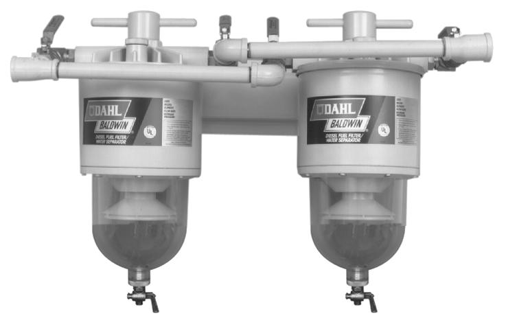


1 200 & 300 SERIES Diesel Fuel/Water Separators Installation Operation Parts Service Information
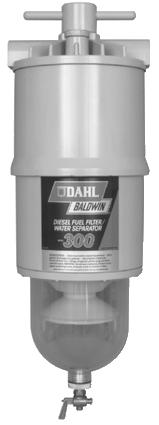
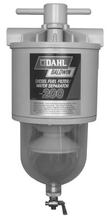
2 INSTALLATION A. FILTER MOUNTED ABOVE FUEL STORAGE TANK 1. Select a location in the fuel line between the fuel tank and the fuel pump, ahead of the vacuum side filters. All secondary or pressure side filters located between the pump and the engine should be serviced and left in place. 2. Mount the DAHL unit vertically on the vacuum (suction) side of all fuel pumps in a convenient location for servicing and inspection of contaminants in the bowl. Locate the height of the unit between the bottom of the fuel tank and the inlet of the fuel pump if possible. See Figure 1. DAHL recommends a 286-SK Mounting Bracket Shock Pad Kit if the filter will be subject to excessive vibration. NOTE: Allow 2 1/2 inches vertical clearance below the unit for servicing the element and draining the contaminants. 3. Install the fuel line from the fuel tank to the DAHL filter INLET using appropriate non-ga l vanized fittings. See DAHL Fittings Chart on Page Install the fuel line from the DAHL filter OUTLET to the INLET of the transfer or fuel pump. N OT E : To obtain maximum element life, remove as much mechanical restriction as possible from the system by doing the follow i n g : a. Remove the primary filter (if this does not affect warranty). b. Use the largest diameter fuel line that is practical. c. Mount the unit as near to the level of the pump as possible. d. Eliminate sharp bends in the fuel lines wherever possible. The best indicator of a fuel element s condition is a vacuum ga u g e. (See 85-VK Series in Form 4005.) A tapped fitting is recommended for mounting the gauge on the OUTLET port of the DAHL filter unit. (Manifold units are already tapped and plugged.) Remove the 1/8 inch plug and install the vacuum gauge there. Fittings and gauges are available from your dealer, or contact Baldwin Filters. Prime the fi l t e r as indicated under ELEMENT REPLACEMENT section. B. FILTER MOUNTED BELOW FUEL STORAGE TANK Installation procedures are the same as above plus an addition to Step 3: A ball- or butterfly-type shut-off valve must be installed ahead of the DAHL unit INLET. See Figure 2. This valve is necessary to shut off the fuel when changing the element. Valves are available from your dealer. NOTE: Va l ve not required when installing DAHL va l ve d manifold units. 2 FIGURE 1 REBUILD PROCEDURE If it is ever necessary to dismantle the unit for inspection and/or possible repairs, refer to the parts illustration. Then follow these simple steps: 1. Refer to appropriate ELEMENT REPLACEMENT steps for disassembly. (Dismount if desired.) 2. R e m ove the socket head bolts from the bowl ring to release the b owl. Stubborn bolts are easily removed by shocking the head. Place the allen wrench into the bolt and lightly rap the wrench with a hammer. Remove the bolt. 3. U n s c r ew the depressurizer cone to inspect the reverse flow va l ve. C a u t i o n : Cone edges are sharp. Use gloves or a rag for protection. MODELS 200 & 300 SPECIFICATIONS AND APPLICATIONS MODEL 200 F l ow Rate: Recommended 120 GPH (U.S.) (454 LPH) Maximum 200 GPH (U.S.) (757 LPH) D i m e n s i o n s : Height 16 3/4 In. (425.5 mm) Depth 7 3/4 In. (196.9 mm) Element Removal Clearance: 2 1/2 In. (63.5 mm) Sump Water Capacity: 24 oz. (708 ml) Water Removal Effi c i e n c y : Virtually 100% Used on: 8 Cylinder Cummins and Detroit Diesel Engines Caterpillar Engines up to Approximately 1,000 HP (Including 399) Most Medium Size Diesel Engines up to Approximately 1,000 HP Trucks, Buses, Construction and Agricultural Equipment Smaller Commercial Boats Medium Size Generators FIGURE 2 4. Check all parts for damage. Replace all damaged parts or hard gaskets. (Order Gasket Kit 200-GK.) 5. Refer to the parts illustration for reassembly. Clean all gasket grooves and contact surfaces of foreign matter. Coat the lid cover and bowl gaskets with grease and all other gaskets and O-Rings with oil. Hand tighten the depressurizer cone and wrench tighten the socket head bolts. 6. Again, refer to ELEMENT REPLACEMENT section to finish reassembly. MODEL 300 F l ow Rate: Recommended 180 GPH (U.S.) (681 LPH) Maximum 325 GPH (U.S.) (1,230 LPH) Dimensions: Height 22 1/4 In. (565.2 mm) Depth 7 3/4 In. (196.9 mm) Element Removal Clearance: 2 1/2 In. (63.5 mm) Sump Water Capacity: 24 oz. (708 ml) Water Removal Effi c i e n c y : Virtually 100% Used on: 12 & 16 Cylinder Cummins and Detroit Diesel Engines EMD and Alco Engines up to 2,000 HP Locomotive s Large Stationary Engines, Boats and Generators A ny Application with #12 Fuel Line Caterpillar Engines (800 HP and up)
3 DAHL FITTINGS CHART 90 Elbow Straight T h r e a d with O-Ring/37 Male JIC Note: Mount Model Before Installing Fittings. O-Ring Seal Fittings Require Care in Installation. DO NOT OVERTIGHTEN. See Instructions Below. FITTING FOR DAHL UNIT THREAD 1 THREAD 2 ORDER NUMBER Series 7/8-14 UNF 3 / x8 OBS 200 Series 7/8-14 UNF 7 / x Series 1 1/16-12 UNF 7 / x10 OBS 300 Series 1 1/16-12 UNF 1 1/ x Elbow Straight T h r e a d with O-Ring/37 Male JIC Drilled & Ta p p e d for #4 Vacuum Gauge Hose 37 Male JIC Straight T h r e a d with O-Ring 37 Female JIC S w i v e l - P u s h - O n Hose Fitting Female Pipe Straight T h r e a d with O-Ring 90 Swivel Elbow Straight Thread with O-Ring/37 Female JIC 90 Swivel Elbow Straight Thread with O-Ring/37 Female JIC Drilled & Tapped for #4 Vacuum Gauge Hose Series 7/8-14 UNF 3 / x 8 D TA 200 Series 7/8-14 UNF 3 / x 8 D T B 200 Series 7/8-14 UNF 3 / x8DTC OBS 200 Series 7/8-14 UNF 3 / x 8 D T D 200 Series 7/8-14 UNF 7 / x 10 D T B 300 Series 1 1/16-12 UNF 7 / x10DTB OBS 300 Series 1 1/16-12 UNF 1 1/ x12DTB OBS 200 Series 7/8-14 UNF 3 / x Series 7/8-14 UNF 7 / x Series 1 1/16-12 UNF 7 / x Series 1 1/16-12 UNF 1 1/ x Series 3 / /2 Hose x8 OBS 200 & 300 Series 7 / /8 Hose x10 OBS 300 Series 1 1/ /4 Hose x Series 7/8-14 UNF 3/8-18 NPT x Series 7/8-14 UNF 1/2-14 NPT x8 OBS 200 Series 7/8-14 UNF 3/4-14 NPT x Series 1 1/16-12 UNF 1/2-14 NPT x Series 1 1/16-12 UNF 3/4-14 NPT x Series 1 1/16-12 UNF 3 / F 200 Series 7/8-14 UNF 1 / D D T 1 Install Out Port First 2 Screw in O-Ring fitting until washer contacts port Hand Tighten Only Do NOT Use Wrench 3 4 Hold fitting by hand in desired position and tighten compression nut with wrench. Adjust Compression Nut All the Way Back YES (Important: Do Not Tighten Further) NO Turn Fitting Counterclockwise to Desired Position CAUTION: Use Low Torque: No More Than 8 Foot Pounds NOTE: Use Same Procedure for In Port. DAHL FITTINGS CROSS-REFERENCE CHART DAHL NUMBER AEROQUIP PARKER IMPERIAL WEATHERHEAD x S x6 OBS S F S O - 6 x 6 C 5515 x x8 OBS S F S O - 8 x 10 C 5515 x 8 x x S F S O - 10 x 10 C 5515 x x10 OBS S x S F S O - 12 x x4 OBS S F S O - 4 x 6 C 5315 x 4 x x S F S O - 6 x 6 C 5315 x 6 x x S F S O - 8 x 10 C 5315 x 8 x x S F S O - 10 x 10 C 5315 x x S C 5315 x 10 x x S F S O - 12 x 12 C 5315 x x B x6 OBS B x8 OBS B x10 OBS B x B x S C 3269 x 6 x x x C 3269 x 10 x x8 OBS S C 3269 x 10 x x C 3269 x 10 x x S C 3269 x 12 x x S C 3269 x 12 x 12 3
4 4 SERVICING DRAINING WATER NOTE: The bowl should always be drained before water or contaminant levels reach the bottom of the depressurizer cone. Check daily with the engine off. Always open the draincock completely to flush particulates out. Failure to do so could cause a leaky valve. A. DAHL Units Mounted HIGHER Than Fuel Storage Tank 1. Turn engine off. Vent the DAHL filter to allow draining. 2. Open the primer plug and then open the draincock and drain all contaminants. A. When To Replace As a general guideline, depending on fuel quality and engine use, elements should be replaced as follows: 1. DAHL 201 and 301 are 2 micron elements which can be used approximately 1000 hours or 40,000 miles. (DAHL 201-W and 301-W are 10 micron elements for use in winter or severe applications and DAHL and are 30 micron elements.) 2. If you have a vacuum gauge, the first replacement should be made at the very first indication of power loss at high RPMs. Make a note of the vacuum gauge reading at this point. The differences in various fuel system requirements make it impossible to predict what this reading will be. Mark the reading on the gauge dial or the unit for future element replacement. B. How To Replace Contaminated Element 1. Open the draincock completely to empty the bowl and flush particulates out. Failure to do so could cause a leaky valve. 2. Loosen the T-Bolt handle to release the filter body from the lid. (It is not necessary to completely remove the T-Bolt from the DAHL filter lid.) Support the filter body with your hand prior to release. 3. Remove the element with a turning motion. At this point, 3. Close the draincock and follow the priming instructions shown below. B. DAHL Units Mounted LOWER Than Fuel Storage Tank 1. Turn engine off and close shut-off valve. (Valved Manifold units may be drained and elements replaced with the engine running at idle. Close inlet and outlet valves to islolate the filter being serviced.) 2. Open the draincock completely and drain all contaminants. 3. Close the draincock and follow the priming instructions shown below. ELEMENT REPLACEMENT TROUBLESHOOTING Engine starting and power loss problems from the fuel system are usually caused by one or more of the following: A. Air Leaks 1. Fittings. Insure the O-Rings on the fittings in the DAHL filter ports are lubricated and not damaged, cracked or dirty. NOTE: When using JIC 37 fittings, be sure only mating JIC 37 fittings are used. Misalignment will occur and air leakage will result from an attempt to fasten a SAE 45 fitting to a JIC 37 fitting. Check for fitting looseness, seat dents, misalignment or unmatched threads. All fittings must be wrench tight. 2. Bubbles In The Bowl. If bubbles appear at the depressurizer cone, a leak is indicated between the fuel tank and the inlet port. NOTE: Old fuel lines (rubber hose or metal tubing) may crack when moved. Check areas around push-on fittings, pipe adapters, hose clamps, etc. If air bubbles appear at the draincock, check for particles stuck in the valve seat or a partly open draincock. Also check for defective, miscentered or unlubricated bowl gaskets. Check the bowl plug O-Ring to make sure it is not cracked or extruded out of place. The bowl plug should be hand tightened only. 3. G a s ke t s. If the lid or bowl has been removed, make sure the ga s ket grooves are clean. Inspect the ga s kets for proper seating in the grooves. Lubricate the ga s ket(s) with oil or grease. you may clean the outside of the filter body. Use only clean diesel fuel or kerosene and wipe clean. 4. Inspect the ejector spring(s) at the bottom of the body. Also check the centerpipe O-Ring and replace if hard or damaged. 5. Remove and replace the lid cover gasket. Be sure the lid groove and body lip are clean. (Grease the lid cover gasket to hold it in place before positioning.) C. Reassembly 1. Lubricate the top and bottom element gaskets. Install the element onto the centerpipe with a turning motion. 2. Fill the filter body with clean diesel fuel to within one inch of the top. 3. Double check the lid cover gasket position in the lid groove. 4. Attach the body to the lid and hand tighten the T-Bolt handle. D. Priming 1. Eliminate air use existing fuel system primer, if so equipped. If not, remove the primer plug and fill to the top with clean diesel fuel. 2. Start engine and check for leaks. NOTE: For any marine or other unit utilizing the heat deflector shield, clean the shield to remove any accumulated diesel fuel. B. Clogging And Restriction 1. Fuel Lines. Check for collapsed lines caused by sharp bends or excessive turns. Check the tank and/or filter shut-off valve(s). 2. Filter Elements. Early clogging can occur from badly contaminated fuel (micro-organism growth, rust, sludge, dirt, etc.) Always carry a spare DAHL element. Asphaltinic materials (fuel oxidation products), which are normally harmless to the injection system, can eventually plug original equipment filters remaining in the fuel system. If problems persist after the DAHL element has been replaced, also replace the other fuel filter elements. 3. Filter Inlet. Severely contaminated fuel may cause inlet plugging. In this event, close the fuel tank supply shut-off valve (if equipped) and disconnect the inlet line. Remove the bowl and clean the inlet. Should the depressurizer cone also be plugged, disassemble and clean out. 4. Bleed Back. If fuel in the DAHL filter bleeds back to the fuel tank, an air leak or reverse flow valve problem is indicated. Inspect fuel lines and fittings first as indicated above. If the reverse flow valve is clogged, use air or clean fuel to flush out. C. Malfunction Of Engine Parts Pre-existing conditions in the pumps and injectors can also cause power loss and engine starting problems. See your equipment dealer if the above troubleshooting guides do not cover your problem. WARNING: Do NOT use gasoline or any form of alcohol or anything containing it inside or outside a DAHL Model 200 or 300 Series Fuel/Water Separator.
 1 200-10P 1 T-Bolt 2 200-14 1 Lid Cover 3 1 Lid Cover Gasket (Incl. in 200-GK) 4 200-16 1 Body 5 1 Bowl Gasket (Incl.")
5 MODEL 200 SPECIFICATIONS & PARTS 120 GPH (U.S.) (454 LPH) 7/8-14 w/o-ring Boss 16 3/4 In. (425.5 mm) 7 1/2 In. (190.5 mm) 7 3/4 In. (196.9 mm) 12 lbs. (5.4 kg) P 1 T-Bolt Lid Cover 3 1 Lid Cover Gasket (Incl. in 200-GK) Body 5 1 Bowl Gasket (Incl. in 200-GK) Bowl Ring Socket Head Bolt 8 1 Reverse Flow Washer (Incl. in 200-GK & 200-DEPR KIT) 9 1 Depressurizer Set (Incl. in 200-DEPR KIT) 10 1 Bowl Collar Primer Plug 12 1 Primer Plug O-Ring (Incl. in 200-GK) 13 1 Nylon Gasket (Incl. in 200-GK) 14 1 Upper T-Bolt Seal (Incl. in 200-GK) 15 1 Lower T-Bolt Seal (Incl. in 200-GK) 16 1 Centerpipe O-Ring (Incl. in 200-GK) ,-W,-30 1 Filter Element Ejector Spring Ejector Spring Clip 20 1 Reverse Flow Gasket (Incl. in 200-GK & 200-DEPR KIT) 21 1 Reverse Flow Ball (Incl. in 200-DEPR KIT) Bowl 23 1 Bowl Plug O-Ring (Incl. in 200-GK) Bowl Plug Draincock MODEL 200-MFV SPECIFICATIONS & PARTS 240 GPH (U.S.) (908 LPH) 3/4-14 NPT 16 3/4 In. (425.5 mm) 23 31/32 In. (608 mm) 10 3/4 In. (273 mm) 35 lbs. (16 kg) 1 1 Manifold Bracket Filter/Separator D 4 90 Swivel 7/8 x 1/2 In /2 In. Pipe-Thread Adapter D 4 1/2 in Butterfly Shut-Off Valve 6 4 1/2 In. Close Nipple 7 1 3/4 x 1/2 x 1/2 In. Tee 8 2 1/2 In. Elbow 9 2 Long Nipple 10 1 Drilled & Tapped Tee /8 In. NTP Plug NOTE: For Aluminum Bowl and Marine Versions of the DAHL Model 200 and 300 Series, Refer to Form
6 MODEL 300 SPECIFICATIONS & PARTS 180 GPH (U.S.) (681 LPH) 1 1/16-12 w/o-ring Boss 22 1/4 In. (565.2 mm) 7 1/2 In. (190.5 mm) 7 3/4 In. (196.9 mm) 16 lbs. (7.3 kg) P 1 T-Bolt Lid Cover 3 1 Lid Cover Gasket (Incl. in 200-GK) Body 5 1 Bowl Gasket (Incl. in 200-GK) Bowl Ring Socket Head Bolt 8 1 Reverse Flow Washer (Incl. in 200-GK & 200-DEPR KIT) 9 1 Depressurizer Set (Incl. in 200-DEPR KIT) 10 1 Bowl Collar Primer Plug 12 1 Primer Plug O-Ring (Incl. in 200-GK) 13 1 Nylon Gasket (Incl. in 200-GK) 14 1 Upper T-Bolt Seal (Incl. in 200-GK) 15 1 Lower T-Bolt Seal (Incl. in 200-GK) 16 1 Centerpipe O-Ring (Incl. in 200-GK) ,-W,-30, -MPG,-CS 1 Filter Element Ejector Spring Ejector Spring Clip Reverse Flow Gasket (Incl. in 200-GK & 200-DEPR KIT) Reverse Flow Ball (Incl. in 200-DEPR KIT) Bowl Bowl Plug O-Ring Bowl Plug Draincock MODEL 300-MF SPECIFICATIONS & PARTS 360 GPH (U.S.) (1,363 LPH) /2 NPT 22 1/4 In. (565.2 mm) 25 In. (635 mm) 12 1/4 In. (311.2 mm) 43 lbs. (19.5 kg) 1 1 Manifold Bracket Filter/Separator F 4 90 Swivel 1 1/16 x 3/4 In In. Long Nipple x 3/4 x 3/4 In. Tee 6 2 3/4 In. Elbow In. Long Nipple 8 1 Drilled & Tapped Tee 9 1 1/8 In. NTP Plug 6


7 360 GPH (U.S.) (1,363 LPH) /2 NPT 22 1/4 In. (565.2 mm) 25 In. (635 mm) 12 1/4 In. (311.2 mm) 46 lbs. (21 kg) 1 1 Manifold Bracket Filter/Separator F 4 90 Swivel 1 1/16 x 3/4 In F 4 3/4 In. Pipe-Thread Adapter F 4 3/4 In. Butterfly Shut-Off Valve 6 4 3/4 In. Close Nipple x 3/4 x 3/4 In. Tee 8 2 3/4 In. Elbow In. Long Nipple 10 1 Drilled & Tapped Tee /8 In. NTP Plug MODEL 300-MFV SPECIFICATIONS & PARTS M F V 3 Three Diesel Fuel Filter/Water Separators Manifolded with Shut-Off Valves to allow continuous operation while servicing is also available. Refer to Model 300-MFV for Parts & Specifications. EXCEPTIONS GPH (U.S.) (2,043 LPH) /4 In. (1,009.7 mm)...85 lbs. (38.6 kg) HOW THE DAHL SYSTEM WORKS The contaminated fuel enters the inlet port. 2. The T-Bolt redirects the fuel dow n ward through the c e n t e r p i p e. 3. Fuel flows through the reverse flow valve. 4. Fuel flow is spread by the depressurizer cone. 5. As fuel is discharged from the depressurizer cone, 80% of contaminant separation takes place. Most of the solid particles and water settle into the quiet zone of the bowl. 6. As the fuel rises upward, any remaining minute water droplets coalesce on cone, baffle and bowl surfaces. Droplet size and weight gradually increase, causing downward flow into the sump. 7. Fuel is filtered completely by the element, which contains HydroShield media. The clean fuel then continues upward through the outlet port and on to the pump and injection system. 7 7


8 DAHL FUEL/WATER SEPARATORS WHY DAHL? Filters are a compromise wherever located. As a one-step strainer, a filter must be porous enough to allow sufficient flow volume. This means the filters which came with the equipment are usually in the micron range. However, if a more efficient media were used, the filter would become clogged very quickly, restricting the flow and resulting in frequent, costly element changes. Not only that, many fuel filters are not designed to remove significant amounts of water, even though water is a primary cause of injector pump and nozzle damage. Water and solid contaminants displace the diesel fuels lubricative coating on precision injection components. The loss of this protection results in wear, erosion, surface pitting and eventual fuel pressure loss. THE SOLUTION DAHL s functional dual chamber, 3-stage diesel fuel filter/water separators provide efficient suction side water separation and contaminant filtration. The key is the unique DAHL patented depressurizer cone, which spreads the flow of the fuel. The fact is, the more area to flow over, the slower the flow and the greater the separation of water and dirt from the fuel. DAHL diesel fuel fi l t e r / water separators have less mechanical flow resistance because the fuel changes direction only once. COMPLETE EFFICIENCY DAHL removes virtually 100% of the water and solid contaminants. BALDWIN LIMITED WARRANTY Baldwin Filters warrants each new Baldwin or DAHL Filter Product to be free from defects in workmanship and material as follows: 1. Housings one year from date of user s purchase. 2. Electronics, Pumps and Motors 90 days from date of user s purchase. 3. Replaceable Elements, Spin-ons, Etc. d u r i n g equipment manufa c t u r e r s recommended filter service interval, if properly installed in a Baldwin recommended application. Baldwin will replace or repair at its option, free of charge, any part still in the Baldwin warranty period found by Baldwin s inspection to be defective when such product is returned to place of purchase or to Baldwin Filters with transportation charges prepaid. S p e c i fically excluded from this warranty is damage resulting from excessive force, negligence, abuse, misuse, misapplication, tampering, improper installation, fire or accident. The warranty will not apply to any filter which has been cut apart or subject to tampering. Also, damage to plastic parts of fuel/water separators caused by the use of fluids containing alcohol is not covered by this warranty. Full details of this warranty are in the Policy and Procedures Manual at the Baldwin or DAHL distributor or may be obtained from Baldwin s Service Engineering Department. Baldwin Filters Kearney NE (800) PROVEN PERFORMANCE DAHL diesel fuel/water separators have been tested and proven over millions of miles and hours under all sorts of conditions. Ask anyone who has used DAHL, or any Baldwin user, as Baldwin Filters makes DAHL products. MARINE DURABILITY Marine units 75, 100-AL, 100-M, 100-M30, 150-AL, 150-M, 200- AL, 200-M, 200-M30, 200-MMV, 200-MMV30, 300-AL, 300-M, 300-MM, 300-MM30, 300-MMV and 300-MMV30 have passed severe U.L. testing. Tests include fire endurance, vibration fatigue, impact and thermal shock. These filters have also met U.S. Coast Guard requirements for Marine Applications. CLEAN FUEL DAHL eliminates nearly all of the engine problems caused by water and solid contaminants in diesel fuel. In addition to saving you the cost of expensive repair bills and aggravation, you can expect: Longer Injection System Component Life Full Power Performance Less Element Replacement Cost SUPERIOR ENGINEERING Die Cast Aluminum Impact-resistant large transparent bowl Element service life is several times longer than conventional Easy to install, service and clean Positive air elimination Advanced spring design assures positive element seal Less mechanical resistance because of streamlined flow path B a ffle system is designed to stop emulsification and disperse trapped air Ball check valve to stop reverse flow Six series specifically designed to fit diesel engines of various capacities Authorized Dealer DAHL Products Division Form 4230 (R 4/08) 2008 Baldwin Filters, Inc. Printed in U.S.A.
MARINE. Diesel Fuel/Water Separators. Installation. Operation. Parts. Service Information
 Diesel Fuel/Water Separators stallation Operation Parts Service formation INSTALLATION A. Filter Mounted Above Fuel Storage Tank. Select a location in the fuel line between the fuel tank and the fuel pump,
RECYCLER, RECYCLER/BLENDER & FUEL TRANSFER MODELS
 RECYCLER, RECYCLER/BLENDER & FUEL TRANSFER MODELS Installation Operation Parts Service Information DAHL Recycler Units efficiently separate water and solid contaminants to maintain stability and purity
DIESEL FUEL FILTER/WATER SEPARATORS & Recycler Systems
 DIESEL FUEL FILTER/WATER SEPARATORS & Recycler Systems DAHL DIESEL FUEL FILTER/WATER SEPARATORS REMOVE DIESEL FUEL SYSTEM PROBLEMS ALONG WITH WATER Water and solid contaminants displace the diesel fuel
Model 100 Series Kits
 Introductory Installation Information 1. Always install DAHL 100 on the vacuum (suction) side of transfer pump and ahead of any other filter: On domestic vehicles, remove the 3/8 inch I.D. hose from the
DIESEL FUEL FILTER/WATER SEPARATORS & Re c ycler/blender Syste m s
 DIESEL FUEL FILTER/WATER SEPARATORS & Re c ycler/blender Syste m s DAHL DIESEL FUEL FILTER/WATER SEPARATORS REMOVE DIESEL FUEL SYSTEM PROBLEMS ALONG WITH WATER Water and solid contaminants displace the
Marine Fuel Filtration. Marine Turbine Series. Stage One: Separation. Stage Two: Coalescing. Stage Three: Filtration. And more
 filter assemblies are designed to be installed on the vacuum side of the fuel transfer pump for best efficiency and protect precision engine components from dirt, rust, algae, asphaltines, varnishes, and
All Racor filter materials and seals are compatible with ultra-low sulphur diesel (ULSD) fuel and B2 to B20 Biodiesel. See Racor bulletin 7679.
 fuel and B2 to B20 Biodiesel. See Racor bulletin 7679.") 000MA Water-in-fuel sensor and indicator. MA units have shielded see-thru bowls; MAM bowls are all-metal. UL-listed drain valve and water sensor probe options are available. Turbine Series Electric Primer
000MA Water-in-fuel sensor and indicator. MA units have shielded see-thru bowls; MAM bowls are all-metal. UL-listed drain valve and water sensor probe options are available. Turbine Series Electric Primer
75500MAX Series and 75500MAXM Series
 75500MAX Series and 75500MAXM Series Marine Fuel Filter/Water Separators Instruction Part Number 15349 Rev E Racor Turbine Series fuel filter/ water separators protect the precision components of your
660R-RAC Series. Gasoline Fuel Filter/Water Separators. Overview: Contact Information: Product Features: Instruction Part Number Rev F
 660R-RAC Series Gasoline Fuel Filter/Water Separators Instruction Part Number 1385 Rev F Overview: Don t be caught in the water without one of these Racor gasoline spin on series filters. These filters
120RMAM Marine Series Fuel Filter/Water Separators
 10RMAM Marine Series Fuel Filter/Water Separators Instruction Part Number 1945 Rev A Overview The 10RMAM fuel filter/water separator features 1/4-18 NPTF inlet and outlet fuel ports and a unitized mounting
320R-RAC Series. Gasoline Fuel Filter/Water Separators. Overview: Contact Information: Product Features: Instruction Part Number Rev.
 30R-RAC Series Gasoline Fuel Filter/Water Separators Instruction Part Number 37 Rev. D Overview: Racor 30R-RAC series filters are designed for high-performance applications, which means your engine will
Marine Turbine Series
 1000MA Water-in-fuel sensor and indicator. All Racor filter materials and seals are compatible with ultra-low sulphur diesel (ULSD) fuel and B2 to B20 Biodiesel. See Racor bulletin 7679. The complete Primer
Product Features: Removes 99% of free water. Available with 2, 10, or 30 micron Aquabloc II media
 120A and 120B Series Fuel Filter/Water Separators Instruction Part Number 10219 Rev B Overview: 120A and 120B fuel filter/water separators are designed to be installed on the suction side of the fuel system
Marine Fuel Filtration Marine 800 Series
 Racor recyclers offer large diesel engine operators both ease of maintenance and continuous engine operation. Continuous operations include filter changeouts and the draining of accumulated water from
Introduction. Marine Turbine Series. Model Illustrations. Special Notes. Specifications 77/1000MA 73/1000MA 75/500MAX 75/900MAX 79/1000MAV 75/1000MAX
 Introduction Model Illustrations 5MA 5MAM 9MA 1MA 7/1MA 77/1MA 75/5MAX Special Notes 75/9MAX 75/1MAX 79/1MAV 1. See--thru bowl MA / MAX / MAV units are approved for Diesel service only. UL Listed, USCG
Racor 75500FGX Turbine Series fuel
 Installation Instructions 75500FGX Fuel Filter Racor 75500FGX Turbine Series fuel filter/water separator assemblies are designed to be installed on the vacuum side of the fuel transfer pump for best efficiency
400 Series Spin-on Fuel Filter/Water Separators
 00 Series Spin-on Fuel Filter/Water Separators Instruction Part Number 09 Rev G 00 Series fuel filter/water separators are designed to handle today s tough fuel filtration problems and can be used anywhere
900MA/MAM and 1000MA/MAM (for marine applications)
") 900MA/MAM and 1000MA/MAM (for marine applications) Fuel Filter/Water Separator Instruction Part Number 19526 Rev B Racor Turbine Series fuel filter/ water separator protects the precision components of
900MA/MAM and 1000MA/MAM (for marine applications) Fuel Filter/Water Separator Instruction Part Number 19526 Rev B Racor Turbine Series fuel filter/ water separator protects the precision components of
Maintenance Manual. Automated Fuel Maintenance System FTI-5A SINGLE TANK FUEL TECHNOLOGIES INTERNATIONAL
 Maintenance Manual Automated Fuel Maintenance System FTI-5A SINGLE TANK FUEL TECHNOLOGIES INTERNATIONAL 05/01/2016 Rev A Fuel Technologies FTI-5A Single Tank Maintenance Section FTI - Fuel Maintenance
General The Racor Marine Diesel Spin--on Series feature a variety of compact sizes to fit most installations and cramped engine compartments.
 Selection Selection Information General The Racor Marine Diesel Spin--on Series feature a variety of compact sizes to fit most installations and cramped engine compartments. Mounting Heads: These units
Maintenance Manual. Automated. Fuel Maintenance System FTI-5A. FUEL TECHNOLOGIES INTERNATIONAL LLC
 Maintenance Manual Automated Fuel Maintenance System FTI-5A FUEL TECHNOLOGIES INTERNATIONAL LLC www.fueltechnologiesinternational.com 03/01/2011 - Fuel Technologies FTI-5A Maintenance Section FTI - Fuel
Product Features. Easy installation. Pump adds only 3.3 to the overall assembly height. 60 GPH (227 LPH) flow rate while in priming mode.
 flow rate while in priming mode.") Primer Pump Kits RKP1912 (12 vdc) and RKP1924 (24 vdc) Instruction Part Number 14356 Rev C Primer pump kits are an innovative and proprietary system consisting of a prescreen filter, a flow by-pass circuit,
Primer Pump Kits RKP1912 (12 vdc) and RKP1924 (24 vdc) Instruction Part Number 14356 Rev C Primer pump kits are an innovative and proprietary system consisting of a prescreen filter, a flow by-pass circuit,
Maintenance Manual WITH ONE SUBMERSIBLE PUMP. Automated Fuel Maintenance System FTI-5A FUEL TECHNOLOGIES INTERNATIONAL LLC
 Maintenance Manual WITH ONE SUBMERSIBLE PUMP Automated Fuel Maintenance System FTI-5A FUEL TECHNOLOGIES INTERNATIONAL LLC Replacement Manuals Available on Website: www.fueltechnologiesinternational.com
BMK-18 U.S. Patent #5,298,158
 BMK- U.S. Patent #5,29,5 Marine Dual Remote Filtration System Mounting Kit Installation and Servicing Instructions IMPORTANT NOTICE Read all instructions completely before attempting to install this unit.
BMK-30. Heavy-Duty By-Pass Filtration System Installation and Servicing Instructions
 BMK-30 Heavy-Duty By-Pass Filtration System Installation and Servicing Instructions IMPORTANT NOTICE Read all instructions completely before attempting to install this unit. Improper installation could
SERVICE PARTS LIST SPECIFY CATALOG NO. AND SERIAL NO. WHEN ORDERING PARTS 13 HP DIRECT DRIVE PRESSURE WASHER CATALOG NO
 SPECIFY CATALOG NO. AND SERIAL NO. WHEN ORDERING PARTS HP DIRECT DRIVE PRESSURE WASHER CATALOG NO. 555-22 SERVICE PARTS LIST STARTING SERIAL NUMBER B06A REVISED BULLETIN PAGE OF BULLETIN NO. 5-20-000 DATE
FPS-500. Fuel Polishing System Eliminates Microbial Contamination. Operating Manual
 FPS-500 Fuel Polishing System Eliminates Microbial Contamination Operating Manual Stabilizes Fuel Removes Water & Sludge Prevents Tank Sediments Improves Engine Reliability Optimizes Fuel Quality Optimal
INSTRUCTION AND MAINTENANCE MANUAL FR95 PRESSURE REGULATOR
 Enidine / Conoflow 105 Commerce Way Westminster, SC 29693 Tel: (864) 647-9521 Fax: (864) 647-7993 WARNING Conoflow s products are designed and manufactured using materials and workmanship required to meet
Hydraulic PTO Flow Device
 Safety, Operation, and Maintenance Manual WARNING Improper use of this tool can result in serious bodily injury This manual contains important information about product function and safety. Please read
SERVICING INSTRUCTIONS
 TSP Series 66 Triplex Plunger Pump SERVICING INSTRUCTIONS TRIPLEX TRIPLEX SERVICING PUMP PROCEDURES Valve Replacement: All inlet and discharge valves can be serviced without disrupting the inlet or discharge
Combustion Technologies By-Pass Filtration Instructions
 Combustion Technologies By-Pass Filtration Instructions www.combustionusa.com Made in the USA Date Revision Jan 17 th, 2013 PLEASE READ AND UNDERSTAND ALL INSTALLATION INSTRUCTIONS PRIOR TO BEGINNING THE
Industrial Pro FH239 Series Filter/Separator/Warmer Installation Instructions
 Industrial Pro FH239 Series Filter/Separator/Warmer Installation Instructions K L Cover Industrial Pro Single Short H I W A B D F P C E J Bottom Bowl G Vent Cap Filter Element (includes part C) I R S T
INSTRUCTIONS AND SERVICE MANUAL WITH PARTS LIST
 CMP SERIES CPM15-15B (25905F300) CPM15-15B-H/D (25905F301) CPM18-15B (25905F303) CPM18-15B-H/D (25905F304) INDUSTRIAL PUMPS INSTRUCTIONS AND SERVICE MANUAL WITH PARTS LIST NOTE! To the installer: Please
Marine Fuel Filtration. Marine FBO. Features:
 The Racor assembly is specifically designed to meet the filtration requirements of today s high pressure common rail diesel injection systems. The unit is used for fuel dispensing pumps or as a primary
Hydraulic Immediate Need Power Pack
 Safety, Operation, and Maintenance Manual WARNING Improper use of this tool can result in serious bodily injury This manual contains important information about product function and safety. Please read
HALLMARK INDUSTRIES INC
 Performance Part No. HP. CONVERTIBLE JET PUMP USER S MANUAL GPH of Water @ Total Discharge Pressure of 40 psi Max. Pressure Max suction (shallow well) Max Suction (deep well) Max GPM (@0 head) Max Discharge
Fuel Pro Series Filter/Separator/Warmer Installation Instructions
 Fuel Pro Series Filter/Separator/Warmer Installation Instructions Standard and Plus Series A B C D Vent Cap and Assembly (part no SP1053) Includes Vent Cap and Vent Cap Seal Part Description Part Number
INSTRUCTION AND MAINTENANCE MANUAL GFH45 PRESSURE REGULATOR
 Enidine / Conoflow 105 Commerce Way Westminster, SC 29693 Tel: (864) 647-9521 Fax: (864) 647-7993 WARNING Conoflow s products are designed and manufactured using materials and workmanship required to meet
Diesel Pro FH235, FH236 and FH241 Series Filter/Separator/Warmer Installation Instructions
 A FH235 Cover Assembly Includes Vent Cap, Vent Cap O-Ring, Collar, Cover, Cover O-Ring, and Spring F E C D I Diesel Pro 235 Diesel Pro FH235, FH236 and FH241 Series Filter/Separator/Warmer Installation
Air Operated 1:1 Oil Ratio Pump OP-11
 INSTRUCTION MANUAL Air Operated 1:1 Oil Ratio Pump OP-11 Congratulations on purchase of this World Class Air Operated Oil Ratio Pump! S1221, Rev C World-class Industrial Oil Dispensing pumps with guaranteed
Spin Klin 3"-4" Apollo Angle
 Spin Klin 3"-4" Apollo Angle w w w. a r k a l - f i l t e r s. c o m 3"-4" Spin Klin Angle Apollo Battery Service & Maintenance Manual Table of Contents Subject Page No. 1. Introduction... 3 2. Safety
Fuel Pro FH230 Series Filter/Separator/Warmer Installation Instructions
 Fuel Pro FH230 Series Filter/Separator/Warmer Installation Instructions A B C Vent Cap and Assembly (part no. 3944440 S) Includes Vent Cap and Vent Cap Seal Parts List Part Description Part Number A Collar
CONTENTS. VIKING PUMP, INC. A Unit of IDEX Corporation Cedar Falls, IA USA SECTION TSM 710.1
 TECHNICAL SERVICE MANUAL industrial heavy duty motor speed pumps SERIES 4076 AND 4176 SIZES hle, ate and ale SECTION TSM 710.1 PAGE 1 of 8 ISSUE B CONTENTS Introduction....................... 1 Safety
Dual Remote Filtration System Installation and Servicing Instructions
 IMPORTANT NOTICE Read all instructions completely before attempting to install this unit. Improper installation could result in serious system and/or equipment damage. The installation of this system is
LABORATORY ZERO AIR GENERATOR MODEL N-GC1500 USER S MANUAL
 LABORATORY ZERO AIR GENERATOR MODEL N-GC1500 USER S MANUAL Content 1. Introduction...2 2. Important safety instruction...3 3. System component...4 4. Engineering design overview...5 5. Installation...6
Electric Diesel Pump EDP/12, EDP/24
 INSTRUCTION MANUAL Electric Diesel Pump EDP/1, EDP/4 S1940, Rev C Congratulations on purchase of this World Class Electric Diesel Pump! Portable Diesel transfer pumps designed for everyday use in Agricultural,
WESTATE DIESEL SYSTEMS
 Centrifugal Filtration for Lubricants and Fluids Mining - Industrial - Marine - Agriculture - Automotive Model 996 Installation Instructions, Parts List and Service Instructions Three connections are required
Maintenance Information
 16573347 Edition 2 February 2014 Air Grinder Series 88H Maintenance Information Save These Instructions Product Safety Information WARNING Failure to observe the following warnings, and to avoid these
CRITICAL FUEL FILTRATION SYSTEM For Fuel Storage Up To 10,000 Gallons (38,000 liters)
") CRITICAL FUEL FILTRATION SYSTEM For Fuel Storage Up To 10,000 Gallons (38,000 liters) Overview Model CF4.0-PLC The Model 4.0-PLC is a fuel polishing system that automatically removes water and debris to
CRITICAL FUEL FILTRATION SYSTEM For Fuel Storage Up To 10,000 Gallons (38,000 liters) Overview Model CF4.0-PLC The Model 4.0-PLC is a fuel polishing system that automatically removes water and debris to
IMPORTANT OPERATING CONDITIONS. Failure to comply with any of these conditions invalidates the warranty. STANDARD CONFIGURATIONS
 X-SERIES TRIPLEX CERAMIC PLUNGER PUMPS OPERATING MANUAL MODELS X8 X10 X20 IMPORTANT OPERATING CONDITIONS Failure to comply with any of these conditions invalidates the warranty. Lubrication - Prior to
Emergency Shear Valves
 Emergency Shear Valves 0060 Underpump Emergency Valve The Emco Wheaton 0060 Emergency Shear Valve incorporates a replaceable shear section and a heat sensitive fusible link assembly. The valve can be manually
4" Spin Klin Twin Apollo Battery. Service & Maintenance Manual
 4" Spin Klin Twin Apollo Battery Service & Maintenance Manual Table of Contents Subject Page No. 1. Introduction... 3 2. Safety Instructions... 3 3. Description and Operation... 4 4. Technical Data...
Spin Klin 4" Apollo Twin
 Spin Klin 4" Apollo Twin w w w. a r k a l - f i l t e r s. c o m 4" Spin Klin Twin Apollo Battery Service & Maintenance Manual Table of Contents Subject Page No. 1. Introduction... 3 2. Safety Instructions...
Fueltec Models 950AW & 955SS Mobile Fuel Tank Cleaning Systems
 Fueltec Models 950AW & 955SS Mobile Fuel Tank Cleaning Systems Operation Manual Fueltec Systems LLC 828-212-1141 www.fueltecsystems.com FEATURES Stainless steel filter housings to resist the acids found
k. Components not properly adjusted. Refer to machine technical manual for proper adjustment of components.
 General Troubleshooting Charts General Troubleshooting Charts Use the charts on the following pages to help in listing all the possible causes of trouble when you begin diagnosing and testing of a machine.
300 Series INSTRUCTION MANUAL. Compressed Air Filters Models 302 (grade) through 317 (grade)
 through 317 (grade)") INSTRUCTION MANUAL 300 Series Compressed Air Filters Models 302 (grade) through 317 (grade) FORM NO.: 3259480 REVISION: 01/2014 READ AND UNDERSTAND THIS MANUAL PRIOR TO OPERATING OR SERVICING THIS PRODUCT.
INSTRUCTION MANUAL 300 Series Compressed Air Filters Models 302 (grade) through 317 (grade) FORM NO.: 3259480 REVISION: 01/2014 READ AND UNDERSTAND THIS MANUAL PRIOR TO OPERATING OR SERVICING THIS PRODUCT.
FUELTEC MODEL CF4.0. CRITICAL FUEL FILTRATION SYSTEM For Fuel Storage Up To 10,000 Gallons (38,000 liters)
") FUELTEC MODEL CF4.0 CRITICAL FUEL FILTRATION SYSTEM For Fuel Storage Up To 10,000 Gallons (38,000 liters) Today s diesel engines require aircraft quality fuel. Not to many years ago diesel engines were
FUELTEC MODEL CF4.0 CRITICAL FUEL FILTRATION SYSTEM For Fuel Storage Up To 10,000 Gallons (38,000 liters) Today s diesel engines require aircraft quality fuel. Not to many years ago diesel engines were
TYPE E Main Valve Sizes 3 /8 through 12
 Technical Data SD 3001E PRINTED IN U.S.A. SD 3001E/9709 SPENCE ENGINEERING COMPANY, INC. 150 COLDENHAM ROAD, WALDEN, NY 12586-2035 A B TYPE E MAIN VALVE FACE TO FACE DIMENSIONS C D E DIMENSIONS (inches)
EJECTORS GENERAL OPERATION & MAINTENANCE MANUAL
 EJECTORS GENERAL OPERATION & MAINTENANCE MANUAL The information contained in this manual was current at the time of printing. The most current versions of all Hydro Instruments manuals can be found on
AIR MOTOR DRIVE
 SERVICE MANUAL EN 31-450 AIR MOTOR DRIVE 77-3140-R1.0 (9/2017) 1 / 8 In this part sheet, the words WARNING, CAUTION and NOTE are used to emphasize important safety information as follows: Hazards or unsafe
D/G-10 Maintenance. Daily. Shutdown Procedure During Freezing Temperatures. Periodically
 D/G-10 Maintenance NOTE: The numbers in parentheses are the Reference Numbers on the exploded view illustrations found in this manual and in the Parts Manual. Daily Check oil level and condition of oil.
DISPLACEMENT PUMP INSTRUCTIONS-PARTS LIST Rev. K. Model , Series A Model , Series B Model , Series A
 INSTRUCTIONS-PARTS LIST INSTRUCTIONS This manual contains important warnings and information. READ AND KEEP FOR REFERENCE. DISPLACEMENT PUMP 308190 Rev. K 3000 psi (210 bar) MAXIMUM WORKING PRESSURE Model
SNAPP. The One-Piece, High-Performance Snap-In Fuel Filter Water Separator. Next
 SNAPP The One-Piece, High-Performance Snap-In Fuel Filter Water Separator 2 Now, getting the fuel filtration you need is a SNAPP. SNAPP. The fuel filter change that changes everything. The world turns
Section 10 Chapter 17
 Section 10 Chapter 17 24 Valve, 8.3 Liter Engine Air Intake System Note: All coding used in the 8.3 Liter and 9 Liter engine manuals are Cummins engine codes. These engine codes have no meaning to New
Air Operated Grease Ratio Pumps 50:1 BGRP
 INSTRUCTION MANUAL S1350, Rev C Air Operated Grease Ratio Pumps 50:1 BGRP Congratulations on purchase of this World Class Air Operated Grease Ratio Pump! World-class Industrial High Pressure Grease pump
1/2" AIR DRIVEN DIAPHRAGM PUMP
 1/2" DRIVEN DIAPHRAGM PUMP OPERATION AND SERVICE GUIDE O-1225D NOV. 2008 Page 1 of 6 Refer to Bulletin P-605, Parts List P-9151 DRIVEN, DOUBLE DIAPHRAGM PUMP MANUAL Congratulations on purchasing one of
FH 230 SERIES FUEL PRO
 FH 230 SERIES FUEL PRO D IESEL F UEL F ILTRATION S YSTEM All-In-One Fuel Filter, Fuel- Water Separator and Fuel Heater Seeing is Believing Eliminates unnecessary changes and maintenance Extended filter
INSTALLATION AND OPERATING
 Publication T5-704, Rev. 4 Dated: November 1, 2006 INSTALLATION AND OPERATING MANUAL T50-P TURBOTWIN Engine Air Starter AN 99-448 TABLE OF CONTENTS Section Subject Page 1.0 General Information. 1 2.0 Orientation
Model Model 815
 Model 600004 Model 600204 Model 85387 Model 600104 Model 815 ir line products and accessories ir couplers and nipples............................... 196 low guns, tire inflators and siphon sprayers.............
High Performance Vacuum Pump Model 15120A/15121A Operating Manual...
 High Performance Vacuum Pump Model 15120A/15121A Operating Manual... Operating Manual Table of Contents Warnings...1 CoolTech high performance vacuum pumps...1 Pump components...2 Before using your vacuum
UNIVERSAL PUMP HANGER INSTALLATION INSTRUCTIONS
 UNIVERSAL PUMP HANGER INSTALLATION INSTRUCTIONS WARNING! THESE INSTRUCTIONS MUST BE READ AND FULLY UNDERSTOOD BEFORE BEGINNING INSTALLATION. FAILURE TO FOLLOW THESE INSTRUCTIONS MAY RESULT IN POOR PERFORMANCE,
CAB TILT HYDRAULIC SYSTEM
 OPERATION, MAINTENANCE and SERVICE INSTRUCTIONS CAB TILT HYDRAULIC SYSTEM WITH POWER-PACKER PUMP, CYLINDERS and LATCHES A division of Actuant Corporation 1-800-745-4142 1 www.powerpackerus.com Notice The
Port size: 1 NPT Shaft size: 5/8 Solid or 1/2 Hollow. Pump shaft rotation: CW Standard/CCW Optional. Weight: 19 lbs. Rollers: Ultra Rollers standard
 4-, 5-, 6-, 7-, 8-Roller Pump Instruction Manual 01509-MN (Read carefully before installation and operation) GENERAL Delavan roller pumps are available with a variety of options, such as a choice of roller
TECHNICAL SERVICE MANUAL
 Electronic copies of the most current TSM issue can be found on the Viking Pump website at www.vikingpump.com TECHNICAL SERVICE MANUAL HEAVY-DUTY Stainless steel BRACKET MOUNTED PUMPS SERIES 127 AND 4127
D-04/G-04 Maintenance
 D-04/G-04 Maintenance NOTE: The numbers in parentheses are the Ref. Nos. on the illustrations in the Parts Manual. Daily Check the oil level and the condition of the oil. The oil level should be 1/4 in.
BMK-27. Dual Remote Filtration System Mounting Kit. Installation and Servicing Instructions (DURAMAX) C. Oil Supply
 C. Oil Supply") IMPORTANT NOTICE Read all instructions completely before attempting to install this unit. Improper installation could result in serious system and/or equipment damage. The installation of this system is
IMPORTANT NOTICE Read all instructions completely before attempting to install this unit. Improper installation could result in serious system and/or equipment damage. The installation of this system is
Fuel Supply Component Description
 1999 Chevrolet/Geo Tahoe - 4WD Fuel Supply Component Description FIGURE Central SFI Fuel System with Fuel Pressure Gauge(c) (1) Fuel Inlet (2) Bleed Hose (3) J 34730-1A Fuel Pressure Gage Assembly (4)
Low Pressure Transfer Systems
 Chapter 7b Low Pressure Transfer Systems Automotive Diesel Technology Understanding & Servicing Contemporary Clean Diesel Technology Gus Wright Low Pressure Transfer Layout of a low-pressure fuel transfer
Operating Manual. High Performance Vacuum Pump Models and 15600
 Operating Manual High Performance Vacuum Pump Models 15400 and 15600 CoolTech High Performance Vacuum Pumps Congratulations on purchasing one of Robinair s top quality CoolTech vacuum pumps. Your pump
BMK-12. Dual-Gard By-Pass Filter Mounting Kit Installation and Servicing Instructions
 BMK-12 Dual-Gard By-Pass Filter Mounting Kit Installation and Servicing Instructions IMPORTANT NOTICE Read all instructions completely before attempting to install this unit. Improper installation could
AIR/HYDRAULIC INJECTION GUN MODEL INSTRUCTIONS
 I. OPERATION & DESCRIPTION The Air / Hydraulic Injection Gun is a high-pressure tool that should be used with caution and according to these instructions. IMPORTANT: The Gun is 0,000 psi rated. Do not
INSTALLATION AND OPERATING MANUAL
 Dated: May 10, 2001 INSTALLATION AND OPERATING MANUAL MODEL: T30-Y TURBOTWIN Engine Air Starter From Tech Development Inc AN96-425 6800 Poe Ave. Dayton OH 45414 Tel: (937) 898-9600 Fax: (937) 898-8431
DATA SHEET 6K151CT2, 6K151CT4, 6K201CT2, 6K201CT4, 6K301CT4, 6K401CT4 OPEN IMPELLER CENTRIFUGAL PUMPS. Stainless Steel Models: SPECIFICATIONS FEATURES
 DATA SHEET OPEN IMPELLER CENTRIFUGAL PUMPS Stainless Steel Models: 6K151CT2, 6K151CT4, 6K1CT2, 6K1CT4, 6K31CT4, 6K1CT4 FEATURES Model 6K1CT2 Shown 34 SS Liquid-end construction offers corrosion resistance
Vane Pumps. Single Stage Single and Double Vane Pumps. Vickers. Overhaul Manual
 Vickers Vane Pumps Overhaul Manual Single Stage Single and Double Vane Pumps V14, 124, 134,144 V19, 129, 139, 149 V15, 125, 135, 145 V35*, 36*, 45*, 46* V18, 128, 138, 148 (V)VF-**-**, (V)VG-**-** Reprinted
Maintenance Information
 16572679 Edition 2 May 2014 Air Drill QP Series Maintenance Information Save These Instructions Product Safety Information WARNING Failure to observe the following warnings, and to avoid these potentially
Hand Expansion Valves Built Stronger to Last Longer Sizes: 6mm (¼ ) to 305mm (4 )
 to 305mm (4 )") Hand Expansion Valves Built Stronger to Last Longer Sizes: 6mm (¼ ) to 305mm (4 ) Bulletin No. 82-00A Suitable For: Ammonia, Fluorocarbons, Nitrogen and Carbon Dioxide Features ASTM 352 LCB Cast Steel
Hand Expansion Valves Built Stronger to Last Longer Sizes: 6mm (¼ ) to 305mm (4 ) Bulletin No. 82-00A Suitable For: Ammonia, Fluorocarbons, Nitrogen and Carbon Dioxide Features ASTM 352 LCB Cast Steel
105 Commerce Way Westminster, SC Tel: (864) Fax: (864)
 Fax: (864)") ITT Conoflow 105 Commerce Way Westminster, SC 29693 Tel: (864) 647-9521 Fax: (864) 647-9574 WARNING Conoflow s products are designed and manufactured using materials and workmanship required to meet all
ITT Conoflow 105 Commerce Way Westminster, SC 29693 Tel: (864) 647-9521 Fax: (864) 647-9574 WARNING Conoflow s products are designed and manufactured using materials and workmanship required to meet all
INSTALLATION INSTRUCTIONS FOR THE TRUCK MOUNTED VIPER ADDITIVE INJECTION SYSTEM GTP-8776C
 INSTALLATION INSTRUCTIONS FOR THE TRUCK MOUNTED VIPER ADDITIVE INJECTION SYSTEM GTP-8776C This additive injection system was designed to be used with five gallon jug of additive. The system is supplied
FPS- 80. Manual. Reverso Pumps, Inc. Ph: (954)
") FPS- 80 Manual Table of Contents System Overview... 1 Control Panel Overview... 2 Technical Specifications... 3 Electrical and Installation... Tank Diagrams... 5 Initial Setup... 6 Digital Timer Instructions:
FPS- 80 Manual Table of Contents System Overview... 1 Control Panel Overview... 2 Technical Specifications... 3 Electrical and Installation... Tank Diagrams... 5 Initial Setup... 6 Digital Timer Instructions:
INSTALLATION INSTRUCTIONS
 INSTALLATION INSTRUCTIONS PERFORMANCE AT THE WHEELS KIT W120-22, W120-23 1964 1/2-69 MUSTANG Thank you for choosing STAINLESS STEEL BRAKES CORPORATION for your braking needs. Pleases take the time to read
OWNER S TECHNICAL MANUAL
 OWNER S TECHNICAL MANUAL 2.5kg Grease Kit 6336 Description The Champion 6336 2.5kg grease kit is a manually operated, spring powered grease kit that comes complete with a hand piece. It is designed to
HYDRAULIC PUMP. INSTALLATION, OPERATION, & MAINTENANCE MANUAL MAINTENANCE MANUAL #: MM-HP Rev. A Page 1 of 12
 INSTALLATION, OPERATION, & #: MM-HP001 4-20-09 Rev. A Page 1 of 12 HYDRAULIC PUMP PART NUMBER HP46982ALSL & HP46982SL HYDRAULIC PUMP MM-HP001 Rev. A Page 2 of 12 Table of Contents 1.0 General Page 3 2.0
OWNERS MANUAL INSTALLATION AND OPERATING INSTRUCTIONS REPAIR PARTS LIST. Centrifugal Pump Primer MODEL 6D, HAN-DEE PRIMER
 OWNERS MANUAL INSTALLATION AND OPERATING INSTRUCTIONS REPAIR PARTS LIST Centrifugal Pump Primer 383 0893 MODEL 6D, HAN-DEE PRIMER IMPORTANT For best possible performance continuous, satisfactory operation,
TECHNICAL SERVICE MANUAL
 TECHNICAL SERVICE MANUAL HEAVY-DUTY bracket mounted PUMPS SERIES 4193 AND 493 SIZES GG - AL SECTION TSM 154 PAGE 1 of 10 ISSUE C CONTENTS Introduction....................... 1 Special Information...................
SECTION ZF FRONT AXLE
 04-101.01/ 1 2011JA14 SECTION 04-101.01 6 3 5 1 2 9 1. Upper radius rod 2. Lower radius rod 3. Caliper 4. BRAKE Disk 5. Pneumatic connector 6. Hub 7. steering knuckle 8. Grease Fitting 9. Pneumatic connector
Page 1 of 19. Part# /10/2006
 Part# 1002733-01 10/10/2006 This manual contains important information concerning the installation and operation of the gun washers listed above. Read manual thoroughly and keep for future reference INSTRUCTIONS
Operating and Maintenance Manual Gas & Diesel Engine Powered Self-Priming Trash Pumps Series
 Operating and Maintenance Manual Gas & Diesel Engine Powered Self-Priming Trash Pumps 3200 Series Operating Manual Contents: Model Number/Serial Number/Safety Information Pg. 1 Safety Information (Con
Maintenance Information
 16573370 Edition 2 February 2014 Air Grinder 99V Series Maintenance Information Save These Instructions Product Safety Information WARNING Failure to observe the following warnings, and to avoid these
LIQUIDYNAMICS Oil Extractors
 LIQUIDYNAMICS Oil Extractors This manual contains important warnings and information. READ AND KEEP FOR REFERENCE. Instruction & Parts Manual Model 24224T 6 gallon Oil Extractor Model 2420 21 gallon Oil
Butterfly Valve Type 57P
 Butterfly Valve Type 57P Contents Lever Type: 50-200 mm (2-8 ) Body Material: CPVC Gear Type: 50-200mm (2-8 ) Body Material: CPVC (1) Be sure to read the following warranty clauses of our product 1 (2)