CONA Further components / Accessories
|
|
|
- Miles Day
- 5 years ago
- Views:
Transcription
 - with socket weld ends (Fig. 665...3) - with butt weld ends (Fig. 665...4) - union with butt weld ends (Fig. 665...5) Grey cast iron Forged steel Fig.")
 - with screwed sockets (Fig. 645/647...2) - with socket weld ends (Fig. 645/647...3) - with butt weld ends (Fig. 645/647...4) Forged steel Fig.")
 - with butt weld ends (Fig. 650...4) Forged steel Fig. 650 Page 6 Fig. 650...1 Automatic air vent for liquid systems PN16 / PN25 / PN40 - with flanges (Fig.")
 Stainless steel Fig. 655 Page 12 Fig.")
1 CONA Further components / Accessories Liquid drainer PN16 / PN40 - with flanges (Fig ) - with screwed sockets (Fig ) - with socket weld ends (Fig ) - with butt weld ends (Fig ) - union with butt weld ends (Fig ) Grey cast iron Forged steel Fig. 665 Page 2 Fig Condensate discharge temperature limiter PN40 - with flanges (Fig. 645/ ) - with screwed sockets (Fig. 645/ ) - with socket weld ends (Fig. 645/ ) - with butt weld ends (Fig. 645/ ) Forged steel Fig. 645/647 (Y) Page 4 Fig Return temperature limiter PN40 - with flanges (Fig ) - with screwed sockets (Fig ) - with socket weld ends (Fig ) - with butt weld ends (Fig ) Forged steel Fig. 650 Page 6 Fig Automatic air vent for liquid systems PN16 / PN25 / PN40 - with flanges (Fig ) - with screwed sockets (Fig ) - with socket weld ends (Fig ) - with butt weld ends (Fig ) Grey cast iron SG iron Stainless steel Fig. 656 Page 10 Fig Vacuum breaker PN16 / PN40 - with screwed sockets (Fig ) Stainless steel Fig. 655 Page 12 Fig HALLE AWH ARMATUREN- WERK HALLE GMBH A member of the ARI group Data sheet englisch (english)
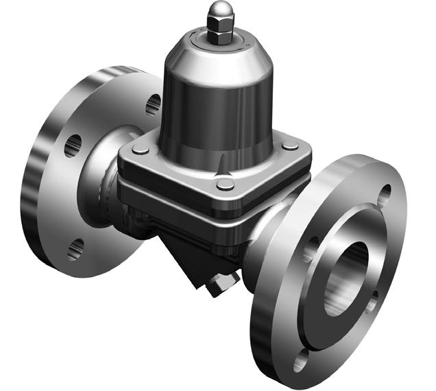
2 Liquid drainer (Grey cast iron, Forged steel) CONA 665 PN16 / PN40 - DN15-25 Fig with screwed sockets Fig with flanges Fig with socket weld ends Fig with butt weld ends Fig Union with butt weld ends (only PN16) Figure pressure Material PN16 EN-JL PN diam. / NPS on request. For ANSI versions refer to data sheet CONA Components-ANSI Operating pressure PS Inlet temperature TS 12,8 barg 200 C 9,6 barg 300 C 32 barg 250 C 22 barg 385 C 14,5 barg 450 C Allow. differential pressure PMX 1,5 bar (Closing pressure, Factory setting) Flanges...1 acc. to DIN 2633 or DIN EN (PN16) / DIN 2635 or DIN EN (PN40) Screwed sockets...2 Rp thread acc. to DIN EN or NPT thread acc. to ANSI B Socket weld ends...3 acc. to DIN EN Butt weld ends...4 Weld preparation acc. to EN ISO 9692 identification No. 1.3 and 1.5 (Note restriction on operating pressure / inlet temperature depending to design!) Union with butt weld ends...5 acc. to data sheet resp. customer request Features Automatic condensate-discharge during start-up and shut down On unpressurized system the liquid drainer will be opened by a compression spring inside of the controller On factory setting the liquid drainer will be closed at a differential pressure of 1,5 bar. Other factory settings between 0,5 bar and 2 bar possible. Bimetallic elements will achieve that the closing pressure is constant Installation in any position (if a frost resistant execution is required please inquire) Selection criteria Closing pressure diameter / pressure Type of connection Material Place of service Other types of connection on request. Example for order data For the condensate discharge from a steam pipe, ΔP=3 bar, max. flow 700 kg/h, flange connection, PN16, DN25 => Liquid drainer, Fig. 665, PN16, DN25, EN-JL1040, Face-to-face dimension 160 mm, with flanges 2
3 Flanges PN16 Union with butt weld ends Flanges PN40 Screwed sockets Socket weld ends CONA 665 PN16 / PN40 - DN15-25 Butt weld ends DN NPS 1 1/2 3/4 1/2 3/4 1 1/2 3/4 1 1/2 3/4 1 Face-to-face acc. to data sheet resp. customer request L (mm) Dimensions Standard-flange dimensions refer to page 14. H (mm) S (mm) HEX (mm) SQR (mm) Weights Fig. 665 (approx.) (kg) 4,5 2,6 2,3 5,4 2,6 2,3 2,2 2,3 2,4 2,9 2,8 2,6 Parts Pos. Sp.p. Description Fig Fig Body EN-GJL-250, EN-JL1040 P250GH, Cover EN-GJL-250, EN-JL Cap -- P250GH, x Sealing ring CU A4 14 Union nut 11SMn30+C, C Welding end C15, x Gasket Pure graphite (CrNi laminated with graphite) x Sealing ring Novapress MULTI x Controller, cpl. TB 102 / 85 (corrosion resistant bimetal) 27 Cheese head screw A Spare parts Information / restriction of technical rules need to be observed! Resistance and fitness must be verified (contact manufacturer for information, refer to Product overview and Resistance list). Operating and installation instructions can be downloaded at Capacity chart The capacity chart shows the maximum flow quantities of cold condensate at about 20 C. Flow (kg/h) Differential pressure considering drainage into atmosphere (bar) 3
4 CONA 645 / 647 PN40 - DN15-25 Condensate discharge temperature limiter (Forged steel) Fig. 645/ with screwed sockets Fig. 645/ with socket weld ends Fig with flanges Fig with flanges Fig. 645/ with butt weld ends Figure (Y) pressure Material PN diam. / NPS For ANSI versions refer to data sheet CONA Components-ANSI Operating pressure PS Inlet temperature TS 32 barg 250 C 22 barg 385 C 14,5 barg 450 C allowable differential pressure ΔPMX for controller 32 bar R32 Other types of connection on request. Flanges...1 acc. to DIN 2635 or DIN EN (PN40) Screwed sockets...2 Rp thread acc. to DIN EN or NPT thread acc. to ANSI B Socket weld ends...3 acc. to DIN EN Butt weld ends...4 Weld preparation acc. to EN ISO 9692 identification No. 1.3 and 1.5 (Note restriction on operating pressure / inlet temperature depending to design!) Features Steam trap for the discharge of condensate without re-evaporation at adjustable condensate temperatures (temperature range from 60 C up to 140 C). With corrosion- and waterhammer resistant bimetallic controller Automatic air-venting during start-up and operation of the installation Installation in any position, except cap upside down Integrated non return protection With inside strainer - Fig. 645 / with outside strainer - Fig. 647 (Y) Subcooling of condensate is continuously adjustable (observe the operation instructions) The exchange of the controller is possible without disturbing the pipe connections For the utilization in warm water and hot water plants (Design refer to page 5) with blow down valve, cpl. (Pos. 46) with thermometer insert (Pos. 47 and 48) (only with inside strainer) Selection criteria Example for order data Inlet pressure Type of connection For the condensate discharge from a steam pipe, Operating pressure P1 = 4 bar(g), max. Flow Back pressure Material 50 kg/h, Opening temperature 80 C, with flanges, PN40, DN25 Quantity of condensate => Condensate discharge temperature limiter, Fig. 647, PN40, DN25, , Face-to-face dimension 160 mm, with flanges, with thermometer. diameter / pressure 4
5 CONA 645 / 647 PN40 - DN15-25 Dimensions and weights Screwed sockets Flanges Butt weld ends Socket weld ends DN NPS 1/2 3/4 1 1/2 3/4 1 1/2 3/4 1 Face-to-face acc. to data sheet resp. customer request L (mm) Dimensions Standard-flange dimensions refer to page 14. H (mm) H1 (mm) S (mm) S1 (mm) HEX (mm) Weights Fig. 645/647 (approx.) (kg) 3,6 4,3 5,6 2 2,4 2,4 2,2 2 2 Parts Pos. Sp.p. Description Fig Fig Body P250 GH, x Strainer X5CrNi18-10, Cap P250 GH, x Strainer -- X5CrNi18-10, x Strainer plug -- X6CrNiTi18-10, x Controller, cpl. TB 102 / 85 (corrosion resistant bimetal) 42 x Sealing ring A4 43 x Screw plug C35E, Blow down valve, cpl. X6CrNiTi18-10, x Thermometer adapter X6CrNiTi18-10, x Thermometer X8CrNiS18-9, Spare parts Information / restriction of technical rules need to be observed! Resistance and fitness must be verified (contact manufacturer for information, refer to Product overview and Resistance list). Operating and installation instructions can be downloaded at Capacity chart Opening temperature 20 C Cold condensate at Outside strainer with blow down valve Flow (kg/h) 10K below opening temperature Differential pressure considering drainage into atmosphere (bar) The capacity chart shows the maximum flow quantities of cold condensate at about 20 C and condensate at 10K below the opening temperature based on the factory setting. Thermometer insert with adapter (Indicating range: 0 C up to 160 C) standard, (up to 250 C on request) 5
6 Return temperature limiter (Forged steel) CONA 650 PN25 / PN40 - DN15-25 Fig with screwed sockets Fig with socket weld ends Fig with flanges Fig with butt weld ends diam. / Figure Material pressure NPS PN For ANSI versions refer to data sheet CONA Components-ANSI Operating pressure PS Inlet temperature TS Allow. differential pressure PMX for controller 22 barg 180 C 6 bar R22 Other types of connection on request. Flanges...1 acc. to DIN 2635 or DIN EN (PN40) Screwed sockets...2 Rp thread acc. to DIN EN or NPT thread acc. to ANSI B Socket weld ends...3 acc. to DIN EN Butt weld ends...4 Weld preparation acc. to EN ISO 9692 identification No. 1.3 and 1.5 (Note restriction on operating pressure / inlet temperature depending to design!) Features Liquid return temperature limiter is applied for the return of hot water or other suitable liquids in heating systems. Temperature guided but operating from the pressure, it is providing a consumption oriented supply of hot water to heating systems. Energy saving by using reduced flow return temperatures. With corrosion- and waterhammer resistant bimetallic controller The controller has a stroke-limitation at 130 C thus even in case of an incorrect setting the function is performed Scope range of closing temperature from: 60 to 130 C The exchange of the controller is possible without disturbing the pipe connections Optimized design for quick installation Maintenance simplified due to screwed cap without sealing Installation: horizontal installation position is preferred, inclined installation position of the screwed cap is possible (Design refer to page 7) with thermometer insert (Pos. 47 and 48) with external adjustment device (pos. 44) and extended setting range, with factory setting at 180 C Selection criteria Example for order data Closing pressure Required closing temperature Operating pressure diameter / pressure Return temperature limitation for a pipe tracing system. Inlet pressure 4 bar (g), closing temperature 90 C, flange connection, PN40, DN15, , face-to-face dimension 150 mm. Back pressure/differential pressure Type of connection => Liquid return temperature limiter, Fig. 650, PN40, DN15, , Flow quantity Material face-to-face dimension 150 mm, T=90 C, flange connection Upstream temperature 6
7 CONA 650 PN25 / PN40 - DN15-25 Flanges Screwed sockets Socket weld ends Butt weld ends DN NPS 1/2 3/4 1 1/2 3/4 1 1/2 3/4 1 Face-to-face acc. to data sheet resp. customer request L (mm) Dimensions Standard-flange dimensions refer to page 14 / Larger nominal diameters refer to page 8. H (mm) H1 (mm) S (mm) HEX (mm) Weights Fig. 650 (approx.) (kg) 3,4 4 4,4 2,1 2 2,5 2,6 2,7 2,8 Parts Pos. Sp.p. Description Fig Body P250 GH, Cap P250 GH, Screw plug C35E, x Sealing ring A4 24 x Controller, cpl. TB 102 / 85 (corrosion resistant bimetal) 44 Cylinder screw HSE (Manual adjustment device) X8CrNiS18-9, x Thermometer adapter X6CrNiTi18-10, x Thermometer X6CrMoTi , Spare parts Information / restriction of technical rules need to be observed! Resistance and fitness must be verified (contact manufacturer for information, refer to Product overview and Resistance list). Operating and installation instructions can be downloaded at Capacity chart The capacity chart shows the maximum capacity at factory setting (90 C). Flow (kg/h) maximum leakage rate at closing temperature The water-temperature determines the degree of opening of the controller. The lower temperature of the water the higher the flow quantity. Change of the factory setting After opening the cap in pressureless mode, an adjustment of the closing temperature can be done. A half turn of the screw clockwise results in an increase of temperature by about 10K. Differential pressure considering drainage into atmosphere (bar) Thermometer insert with adapter (Anzeigebereich: 0 C to 160 C) standard, (to 250 C acc. to customer request) External adjustment 7
8 Return temperature limiter (Forged steel) CONA 650 PN25 / PN40 - DN40-50 Fig with screwed sockets Fig with socket weld ends Fig with flanges Fig with butt weld ends Figure Material pressure diameter / NPS / PN /2-2 For ANSI versions refer to data sheet CONA Components-ANSI Operating pressure PS Inlet temperature TS Allow. differential pressure PMX 22 barg 180 C 6 bar Other types of connection on request. Flanges...1 acc. to DIN 2634 or DIN EN (PN25) / DIN 2635 or DIN EN (PN40) Screwed sockets...2 Rp thread acc. to DIN EN or NPT thread acc. to ANSI B Socket weld ends...3 acc. to DIN EN Butt weld ends...4 Weld preparation acc. to EN ISO 9692 identification No. 1.3 and 1.5 (Note restriction on operating pressure / inlet temperature depending to design!) Features Liquid return temperature limiter is applied for the return of hot water or other suitable liquids in heating systems. Temperature guided but operating from the pressure, it is providing a consumption oriented supply of hot water to heating systems. Energy saving by using reduced flow return temperatures. With corrosion- and waterhammer resistant bimetallic controller Scope range of closing temperature from up to 180 C With external adjustment device (pos. 44) and extended setting range With factory setting 90 C The exchange of the controller is possible without disturbing the pipe connections Optimized design for quick installation (Design refer to page 9) with thermometer insert (Pos. 47 and 48) Selection criteria Example for order data Closing pressure Required closing temperature Return temperature limitation for a pipe tracing system.. Inlet pressure 4bar(ü), closing Operating pressure diameter / pressure temperature 90 C, flange connection, PN40, DN15, , Back pressure/differential pressure Type of connection Face-to-face dimension 230mm. Flow quantity Material => Return temperature limiter, Fig. 650, PN40, DN40, , face-to-face dimension 230mm, T=90 C, flange connection Upstream temperature 8
9 CONA 650 PN25 / PN40 - DN40-50 Flanges Screwed sockets 1) Socket weld ends Butt weld ends DN NPS 1 1/ / /2 2 Face-to-face acc. to data sheet resp. customer request L (mm) / 160 1) Dimensions Standard-flange dimensions refer to page 14 / Smaller nominal diameters refer to page 6. H1 (mm) S (mm) SQR (mm) Weights Fig. 650 (approx.) (kg) 11,3 12, ,9 9,8 Parts Pos. Sp.p. Description Fig Body P250 GH, Cover P250 GH, Screw plug X6CrNiTi18-10, Sealing ring A4 24 x Controller, cpl. TB 102 / 85 (corrosion resistant bimetal) 26 x Gasket Graphite 27 Cheese head screw 21CrMoV 5-7, x Sealing ring Cu 44 Cylinder screw HSE (Manual adjustment device) X8CrNiS18-9, x Thermometer adapter X6CrNiTi18-10, x Thermometer X6CrMoTi , x O-ring FPM 80 Spare parts Information / restriction of technical rules need to be observed! Resistance and fitness must be verified (contact manufacturer for information, refer to Product overview and Resistance list). Operating and installation instructions can be downloaded at Capacity chart The capacity chart shows the maximum capacity at factory setting (90 C). Flow (kg/h) maximum leakage rate at closing temperature The water-temperature determines the degree of opening of the controller. The lower temperature of the water the higher the flow quantity. Change of the factory setting A half turn of the screw clockwise results in an increase of temperature by about 8K. Differential pressure considering drainage into atmosphere (bar) Thermometer insert with adapter Indicating range: 0 C to 160 C) standard, (to 250 C customer request) 9
10 Automatic air vent for liquid systems (SG iron, Cast steel, Stainless steel) CONA 656 PN16 / PN25 / PN40 - DN15-25 Fig with screwed sockets Fig with socket weld ends Fig (PN16) with screwed sockets Fig with flange aeration Fig with butt weld ends venting Figure Material pressure diameter / NPS PN16 EN-JS PN N PN N PN PN For ANSI versions refer to data sheet CONA Components-ANSI Operating pressure PS Inlet temperature TS allowable differential pressure ΔPMX for controller 14 barg 300 C 14 bar R14 21 barg 225 C 21 bar R21 21 barg 400 C 21 bar R21 21 barg 300 C 21 bar R21 21 barg 300 C 21 bar R21 Other types of connection on request. Inlet: Flanges...1 acc. to DIN 2633 or DIN EN (PN16) / DIN 2635 or DIN EN (PN25/40) Screwed sockets...2 Rp thread acc. to DIN EN or NPT thread acc. to ANSI B Socket weld ends...3 acc. to DIN EN Butt weld ends...4 Weld preparation acc. to EN ISO 9692 identification No. 1.3 and 1.5 (Note restriction on operating pressure / inlet temperature depending to design!) Outlet: M14 x 1,5 DIN 13 Features Automatic air vents for liquid systems Hood with flanged cover The exchange of the controller is possible without disturbing the pipe connections Installation: above the point being vented, inlet always at the bottom (Design refer to page 11) Drip pipe (Pos. 54) with Union M14x1,5 for Pipe-ø 8 mm (Pos. 53) Selection criteria Example for order data Operating pressure Back pressure/differential pressure Operating temperature Flow quantity diameter / pressure Type of connection Material Automatic air vents for liquid systems, PS = 21 barg, TS = 400 C, flange connection, PN25, DN25, Hood Cast steel / Cover Forged steel => Automatic air vent for liquid systems, Fig. 656, PN25, DN25, /1.0619, Face-to-face dimension 119 mm, R21, flange connection 10
 Screwed sockets: L = 140 Face-to-face acc. to data sheet resp. customer request L (mm) 119 119 119 119 119 119 119 119 119 Dimensions Standard-flange dimensions refer to page 14.")
11 CONA 656 PN16 / PN25 / PN40 - DN15-25 Flanges Screwed sockets 1) Socket weld ends (not in EN-JS1049) Butt weld ends (not in EN-JS1049) DN NPS 1/2 3/4 1 1/2 3/4 1 1/2 3/4 1 1) Screwed sockets: L = 140 Face-to-face acc. to data sheet resp. customer request L (mm) Dimensions Standard-flange dimensions refer to page 14. H (mm) ) / S (mm) Weights Fig. 656 (approx.) (kg) 4,8 5,3 5,6 4,3 4,4 4,4 4,3 4,4 4,4 Parts Pos. Sp.p. Description Fig Fig Fig Fig Fig Cover P250GH, X6CrNiTi18-10, x Sealing ring A4 A4 EN-JS1049, 16 Hood EN-GJS U-LT GP240GH+N, N GX5CrNi19-10, x Gasket Pure graphite CrNi laminated with graphite 24 x Controller, cpl. X5CrNi18-10, Cheese head screw A CrMoV 5-7, A x Union for drip pipe X6CrNiMoTi , x Drip pipe X6CrNiMoTi , Spare parts Information / restriction of technical rules need to be observed! Resistance and fitness must be verified (contact manufacturer for information, refer to Product overview and Resistance list). Operating and installation instructions can be downloaded at Capacity chart Flow in standard condition ( dm 3 /s) Flow in standard condition (m 3 /h) Differential pressure considering drainage into atmosphere (bar) The diagram shows the maximum discharge of air at standard condition. Drip pipe (angle) with union joint For higher performance with mounted vacuum breaker (BR655) Fig. 655 Flow in standard condition ( dm 3 /s) Flow in standard condition (m 3 /h) Connector Differential pressure (low pressure in bar) The diagram shows the maximum discharge of air at standard conditions with mounted vacuumbreaker. with connector and vacuum breaker (BR655) 11
12 Vacuum breaker (Stainless steel) CONA 655 PN16 / PN40 - Rp1/2 Air inlet System connection Fig with screwed sockets Figure pressure Material NPS Operating pressure PS Inlet temperature TS Set pressure Kvs-value PN Rp 1/2 13 barg 400 C 7 mbar 0,55 m3/h PN Rp 1/2 For ANSI versions refer to data sheet CONA Components-ANSI 13 barg 400 C 21 barg 220 C 7 mbar 0,55 m3/h Other types of connection on request. System connection...2 Rp 1/2 (DIN EN ) / NPT 1/2 (ANSI B1.20.1) A dropping line can be connected. Air inlet Rp 1/8 (DIN EN ) / NPT 1/8 (ANSI B1.20.1) The line has to be led to an outlet. Features Ventilation valve for pipelines, condensing vapour (steam) or liquid systems, where the system pressure should not fall below the atmospheric pressure. Vertical position, cap on top. System connection downwards. Selection criteria Example for order data Operating pressure diameter / pressure Vacuum breaker, System connection Rp, PN 40, NPS 1/2, Operating temperature Type of connection => Vacuum breaker, Fig. 655, PN 40, DN 1/2, System connection Rp. Flow quantity Material 12
13 CONA 655 PN16 / PN40 - Rp1/2 System connection (Rp / NPT) NPS 1/2 Dimensions H (mm) 62 B (mm) 35 S (mm) 10 HEX (mm) 32 Weights Fig. 655 (approx.) (kg) 0,38 Parts Pos. Sp.p. Description Fig / Body X5CrNi18-10, Valve ball X5CrNiMo , Cap X17CrNi16-2, Spare parts Information / restriction of technical rules need to be observed! Resistance and fitness must be verified (contact manufacturer for information, refer to Product overview and Resistance list). Operating and installation instructions can be downloaded at x (cpl. unit) Capacity chart Flow of air in standard condition (l/s) Flow of air in standard condition (m 3 /h) Differential pressure in mbar The diagram shows the maximum discharge of air at standard conditions 13
14 CONA Components / Accessories Informations about pipe welding / Standard-flange dimensions Informations about pipe welding Welding groove acc. to DIN 2559 The material used for ARI valves with butt weld ends are: N GP240GH+N acc. to DIN EN P250GH acc. to DIN EN Note: C15 acc. to DIN Note restriction on operating pressure / inlet temperature depending to design! GX5CrNiMo acc. to DIN EN Due to our experience, we recommend to apply an electric welding process. Because of the different material compositions and wall thickness of the steam traps and the pipe gas welding shall not be applied. Quenching cracks and coarse grain structure may develop. On bimetallic steam traps face-to-face of 95 mm or less, the bimetallic controller has to be disassembled prior to welding. After the traps have cooled down to the ambient temperature the bimetallic controller shall be fitted again into the body. Steam traps with socket-weld ends shall only be welded by arc welding (welding process 111 acc. to DIN EN 24063). If during the time of warranty others than the manufacturer or by the manufacturer authorized persons are interfering in the product and/or the setting, the right of claim for warranty will lapse! Standard-flange dimensions acc. to DIN 2533 / DIN 2634 / DIN 2635 or DIN EN / -1 DN NPS 1/2 3/ /4 1 1/ / / ØD (mm) PN16 ØK (mm) n x Ød (mm) 4 x 14 4 x 14 4 x 14 4 x 18 4 x 18 4 x 18 4 x 18 8 x 18 8 x 18 8 x 18 8 x x x 26 ØD (mm) PN25 ØK (mm) n x Ød (mm) 4x14 4x14 4x14 4x18 4x18 4x18 8x18 8x18 8x22 8x26 8x26 12x26 12x30 ØD (mm) PN40 ØK (mm) n x Ød (mm) 4 x 14 4 x 14 4 x 14 4 x 18 4 x 18 4 x 18 8 x 18 8 x 18 8 x 22 8 x 18 8 x x x 33 HALLE AWH ARMATUREN- WERK HALLE GMBH A member of the ARI group QUA LI TY MANAGEMENT SY S T EMS ISO 9001 WHG 19 I Technology for the Future. G E R M A N Q U A L I T Y V A L V E S ARI-Armaturen Albert Richter GmbH & Co. KG, D Schloß Holte-Stukenbrock, Tel / 994-0, Telefax / or 159 Internet: info.vertrieb@ari-armaturen.com 14
CONA ANSI Further components / Accessories
 CONA ANSI Further components / Accessories Liquid drainer ANSI150 / 300 - with flanges (Fig. 665...1) - with screwed sockets (Fig. 665...2) - with socket weld ends (Fig. 665...3) - with butt weld ends
Grey cast iron Fig. 600 Page 2. Forged steel High temperature steel Stainless steel Fig. 600/601 (Y) DN15-25 Page 4 DN40-50 Page 6
 DN15-25 Page 4 DN40-50 Page 6") Bimetallic steam trap CONA B Bimetallic steam trap Bimetallic steam trap PN16 - with flanges (Fig. 600...1) - union with butt weld ends (Fig. 600...5) Grey cast iron Fig. 600 Page 2 Bimetallic steam trap
Bimetallic steam trap CONA B Bimetallic steam trap Bimetallic steam trap PN16 - with flanges (Fig. 600...1) - union with butt weld ends (Fig. 600...5) Grey cast iron Fig. 600 Page 2 Bimetallic steam trap
Grey cast iron Fig. 610 Page 2. Forged steel Stainless steel Fig. 610/612 (Y) Page 4
 Page 4") Thermostatic steam trap CONA M Thermostatic steam trap Thermostatic steam trap PN16 - with flanges (Fig. 610...1) - union with butt weld ends (Fig. 610...5) Grey cast iron Fig. 610 Page 2 Thermostatic
Thermostatic steam trap CONA M Thermostatic steam trap Thermostatic steam trap PN16 - with flanges (Fig. 610...1) - union with butt weld ends (Fig. 610...5) Grey cast iron Fig. 610 Page 2 Thermostatic
Forged steel Stainless steel Fig. 60A Page 2. Forged steel Stainless steel Fig. 61A Page 4. Forged steel Stainless steel Fig.
 CONA All-in-one - Steam trap station with integrated inlet and outlet valves CONA All-in-one Steam trap station with integrated inlet and outlet valves CONA B All-in-one Bimetallic steam trap PN40 - with
Grey cast iron SG iron Cast steel/ Forged steel High temperature steel Stainless steel Fig. 631 Page 2
 CONA S Ball float steam trap Ball float steam trap Ball float steam trap PN16 / PN40 - with flanges (Fig. 631...1) - with screwed sockets (Fig. 631...2) - with socket weld ends (Fig. 631...3) - with butt
Grey cast iron SG iron Forged steel/ Cast steel Stainless steel Fig. 631 Page 2. High temperature steel Fig. 631 / Fig. 632 Page 8
 Ball float steam trap CONA S Ball float steam trap Ball float steam trap PN16 / PN40 - with flanges (Fig. 631...1) - with screwed sockets (Fig. 631...2) - with socket weld ends (Fig. 631...3) - with butt
AWH ARMATUREN- WERK HALLE GMBH. Thermodynamic steam trap. Thermodynamic steam trap. Thermodynamic steam trap PN40. Thermodynamic steam trap PN63
 TD PN40 - with flanges (Fig. 640/641...1) - with screwed sockets (Fig. 640/641...2) - with socket weld ends (Fig. 640/641...3) - with butt weld ends (Fig. 640/641...4) Forged steel High temperature steel
Forged steel High temperature steel Stainless steel Fig. 640/641 (Y) Page 2. High temperature steel Fig. 640/641 (Y) Page 6
 Page 2. High temperature steel Fig. 640/641 (Y) Page 6") Thermodynamic steam trap CONA TD Thermodynamic steam trap Thermodynamic steam trap PN40 - with flanges (Fig. 640/641...1) - with screwed sockets (Fig. 640/641...2) - with socket weld ends (Fig. 640/641...3)
Thermodynamic steam trap CONA TD Thermodynamic steam trap Thermodynamic steam trap PN40 - with flanges (Fig. 640/641...1) - with screwed sockets (Fig. 640/641...2) - with socket weld ends (Fig. 640/641...3)
High temperature steel Fig. 600 Page 8. High temperature steel Fig. 600 Page 10. High temperature steel Fig. 600 Page 12
 Bimetallic steam trap CONA B ANSI Bimetallic steam trap Bimetallic steam trap ANSI150 / - with flanges (Fig. 600/601...1) - with screwed sockets (Fig. 600/601...2) - with socket weld ends (Fig. 600/601...3)
Grey cast iron SG iron Cast steel Forged steel High temperature steel Stainless steel Fig. 631 Page 2
 Ball float steam trap CONA S ANSI Ball float steam trap Ball float steam trap ANSI125 / 150 / 300 - with flanges (Fig. 631...1) - with screwed sockets (Fig. 631...2) - with socket weld ends (Fig. 631...3)
High temperature steel Fig. 600 Page 8. High temperature steel Fig. 600 Page 10. High temperature steel Fig. 600 Page 12
 Bimetallic steam trap CONA B ANSI Bimetallic steam trap Bimetallic steam trap ANSI150 / - with flanges (Fig. 600/601...1) - with screwed sockets (Fig. 600/601...2) - with socket weld ends (Fig. 600/601...3)
Forged steel Fig. 640/641 (Y) Page 6
 Page 6") Thermodynamic steam trap CONA TD ANSI Thermodynamic steam trap Thermodynamic steam trap ANSI150 / - with flanges (Fig. 640/641...1) - with screwed sockets (Fig. 640/641...2) - with socket weld ends (Fig.
Thermodynamic steam trap CONA TD ANSI Thermodynamic steam trap Thermodynamic steam trap ANSI150 / - with flanges (Fig. 640/641...1) - with screwed sockets (Fig. 640/641...2) - with socket weld ends (Fig.
Forged steel Stainless steel Fig. 610/612 (Y) Page 2. Forged steel Fig. 616 Page 6
 Page 2. Forged steel Fig. 616 Page 6") Thermostatic steam trap CONA M ANSI Thermostatic steam trap Thermostatic steam trap ANSI150 / - with flanges (Fig. 610/612...1) - with screwed sockets (Fig. 610/612...2) - with socket weld ends (Fig. 610/612...3)
Thermostatic steam trap CONA M ANSI Thermostatic steam trap Thermostatic steam trap ANSI150 / - with flanges (Fig. 610/612...1) - with screwed sockets (Fig. 610/612...2) - with socket weld ends (Fig. 610/612...3)
CONA -control Monitoring system for steam traps
 CONA -control - Monitoring system for steam traps CONA -control Monitoring system for steam traps Central status indication External test chamber Bolt-on test chamber Inclusive: - AS-i-Master - Power supply
ARI-Strainer. ARI-Strainer - Screen and supporting basket made of stainless steel. ARI-Strainer - Y-pattern with flanges
 ARI-Strainer ARI-Strainer - Screen and supporting basket made of stainless steel ARI-Strainer - Y-pattern with flanges TRB 801 Annex II No. 45 (except EN-JL1040) EN ISO 15848-1 / TA - Luft TÜV-Test-No.
Forged steel High temperature steel Stainless steel BR 640 / BR 641 (Y) Page 2. with system connectors. Stainless steel BR 642 / BR 643 (Y) Page 4
 Page 2. with system connectors. Stainless steel BR 642 / BR 643 (Y) Page 4") Thermodynamic steam traps TRACO CONA TD Thermodynamic steam trap PN40 - with flanges (BR 640/641...1) - with screwed sockets (BR 640/641...2) - with socket weld ends (BR 640/641...3) - with butt weld ends
Thermodynamic steam traps TRACO CONA TD Thermodynamic steam trap PN40 - with flanges (BR 640/641...1) - with screwed sockets (BR 640/641...2) - with socket weld ends (BR 640/641...3) - with butt weld ends
Pressure reducing valve Pressure reducing valve in straightway form DN
 Pressure reducing valve Pressure reducing valve in straightway form DN 15-150 ARI-PREDU Pressure regulating valve, straight through with diaphragm actuator DMA Actuator with rolling diaphragm Grey cast
ARI-Strainer. Strainer - Screen and supporting basket made of stainless steel. ARI-Strainer - Y-pattern with flanges
 Strainer - Screen and supporting basket made of stainless steel ARI-Strainer - Y-pattern with flanges TRB 801 Annex II No. 45 (except EN-JL1040) German TA - Luft TÜV-Test-No. 922-9204866 Grey cast iron
ARI-Strainer PN63-160
 ARI-Strainer PN63-160 ARI-Strainer - Screen of stainless steel DN 10-100 ARI-Strainer - Straight through with flanges TRB 801 Annex II No. 45 Cast steel Forged steel High temp. Steel Fig. 050 Page 2 +
Excess pressure regulator Excess pressure regulator, straight through DN
 ARI-PREDEX Excess pressure regulator Excess pressure regulator, straight through DN 15-150 ARI-PREDEX Excess pressure regulator, straight through with diaphragm actuator UDA Actuator with rolling diaphragm
Float-operated condensate pump ARI Condensate pump (mechanical) Displacement: 16,5-20 litres. High temperature steel. Stainless steel.
 Displacement: 16,5-20 litres. High temperature steel. Stainless steel.") Float-operated condensate pump ARI Condensate pump (mechanical) Displacement: 16,5-20 litres Condensate pump No electricity required / float-operated PN 16 (82.691) Body: Jacket P235GH-TC, Bottom flanges
Float-operated condensate pump ARI Condensate pump (mechanical) Displacement: 16,5-20 litres Condensate pump No electricity required / float-operated PN 16 (82.691) Body: Jacket P235GH-TC, Bottom flanges
ARI-CHECKO -V / -D Check valve ARI-Check valve, metallic sealing
 ARI-CHECKO -V / -D Check valve ARI-Check valve, metallic sealing Straight through with flanges (except EN-JL1040) Straight through with flanges Straight through with flanges Angle pattern with flanges
ARI-FABA LA Stop valve with bellows seal Free of maintenance stop valve with bellow seal - metallic sealing - long construction
 ARI-FABA LA Stop valve with bellows seal Free of maintenance stop valve with bellow seal - metallic sealing - long construction ARI-FABA LA - Straight through with flanges EN ISO 15848-1 / TA - Luft TÜV-Test-No.
Strainer. ARI-Strainer. ARI-Strainer Y-pattern with flanges. ARI-Strainer Y-pattern with flanges. ARI-Strainer Y-pattern with butt weld ends
 Strainer ARI-Strainer ARI-Strainer Y-pattern with flanges German "TA-Luft" TÜV-Test-No. 922-9204866 TRB 801 No. 45 (except cast iron) Cast iron Nodular iron Cast steel BR 050 Page 2 ARI-Strainer Y-pattern
ARI-STOBU PN16-40 Stuffing box valve Stop valve with gland seal metal seat
 ARI-STOBU PN16-40 Stuffing box valve Stop valve with gland seal metal seat Straight through with flanges TRB 801 Annex II No. 45 (except EN-JL1040) (optional) Straight through with flanges TRB 801 Annex
ARI-Check valve. ARI-Check valve, metallic sealing. ARI-Check valve - Straight through with flanges. ARI-Check valve - Straight through with flanges
 ARI-Check valve, metallic sealing Straight through with flanges (except EN-JL1040) Grey cast iron SG iron Cast steel Fig. 003/303 Page 2 Straight through with flanges Straight through with flanges Angle
Temperature regulator Temperature regulator DN
 Temperature regulator Temperature regulator DN 15-100 Fig. 771 ARI-TEMPTROL Thermal closing valve straight through with flanges Fig. 771 Fig. 772 Page 2 Fig. 773 ARI-TEMPTROL LCG Thermal closing valve
ARI-STEVI 450 / 451 (DN15-150) Control valve - 3-way-form (mixing/diverting valve) (optional with screwed seat ring)
 Control valve - 3-way-form (mixing/diverting valve) (optional with screwed seat ring)") With pneumatic and electric actuators ARI-STEVI 450 / 451 (DN15-150) Control valve - 3-way-form (mixing/diverting valve) (optional with screwed seat ring) ARI-STEVI 450 / 451 Pneumatic actuator ARI-DP
With pneumatic and electric actuators ARI-STEVI 450 / 451 (DN15-150) Control valve - 3-way-form (mixing/diverting valve) (optional with screwed seat ring) ARI-STEVI 450 / 451 Pneumatic actuator ARI-DP
ARI-STEVI 450 / 451 Pneumatic actuator ARI-DP 32-34T. Electric actuator ARI-PREMIO 2,2-25 kn ARI-PREMIO-Plus 2G 2,2-25 kn
 ARI-STEVI 450 / 451 (DN15-150) Control valve - 3-way-form (mixing/diverting valve) (optional with screwed seat ring) With pneumatic and electric actuators ARI-STEVI 450 / 451 Pneumatic actuator ARI-DP
ARI-STEVI 450 / 451 (DN15-150) Control valve - 3-way-form (mixing/diverting valve) (optional with screwed seat ring)
 Control valve - 3-way-form (mixing/diverting valve) (optional with screwed seat ring)") With pneumatic and electric actuators Control valve - 3-way-form (mixing/diverting valve) (optional with screwed seat ring) ARI-STEVI 450 / 451 Pneumatic actuator ARI-DP 32-34T Reversible pneumatic actuator
With pneumatic and electric actuators Control valve - 3-way-form (mixing/diverting valve) (optional with screwed seat ring) ARI-STEVI 450 / 451 Pneumatic actuator ARI-DP 32-34T Reversible pneumatic actuator
with electric and pneumatic actuators Stop valve in straightway form DN ARI-STEVI 405 / 460 Electric actuator AUMA SA with LE
 with electric and pneumatic actuators Stop valve in straightway form DN 300-500 ARI-STEVI 405 / 460 Electric actuator AUMA SA with LE Electric multiturn actuator capable of high closing pressures Enclosure
ARI-STEVI 423 / 463 Pneumatic actuator ARI-DP 34-34T. Electric actuator ARI-PREMIO 5-25 kn ARI-PREMIO-Plus 2G 5-25 kn
 Control valve - 3-way-form (mixing/diverting valve) (optional with screwed seat ring) With pneumatic and electric actuators ARI-STEVI 423 / 463 Pneumatic actuator ARI-DP 34-34T Reversible pneumatic actuator
with electric actuators Feedwater control valve with pump spill back DN
 ARI-STEVI 453 with electric actuators Feedwater control valve with pump spill back DN 25-100 ARI-STEVI 453 Electric actuator ARI-PREMIO 2,2-15 kn ARI-PREMIO-Plus 2G 2,2-15 kn Enclosure IP 65 2 torque switches
ARI-STOBU PN16-40 Stuffing box valve
 Stuffing box valve Stop valve with gland seal - metallic sealing Straight through with flanges TRB 801 Annex II No. 45 (except EN-JL1040) German TA-Luft TÜV-Test-No. 922-9204866 Grey cast iron SG iron
ARI-STEVI 448 / 449 (DN15-100) Control valve in straightway form with screwed seat ring With pneumatic and electric actuators
 Control valve in straightway form with screwed seat ring With pneumatic and electric actuators") ARI-STEVI 8 / 9 (DN5-00) Control valve in straightway form with screwed seat ring With pneumatic and electric actuators ARI-STEVI 8 / 9 Pneumatic actuator ARI-DP 30-3 Reversible pneumatic actuator Actuator
ARI-STEVI 8 / 9 (DN5-00) Control valve in straightway form with screwed seat ring With pneumatic and electric actuators ARI-STEVI 8 / 9 Pneumatic actuator ARI-DP 30-3 Reversible pneumatic actuator Actuator
with pneumatic actuator Pneumatic process valve, Y-pattern DN ARI-STEVI AS 350 Pneumatic actuator - with screwed sockets
 with pneumatic actuator Pneumatic process valve, Y-pattern DN 15-50 ARI-STEVI AS 350 - with screwed sockets Piston actuator Required air supply pressure, max. 10 bar Operating pressure, max. 16 bar Page
ARI-STEVI BBD 415 (DN25-50) Straight through blow down valve
 Straight through blow down valve") With pneumatic actuator ARI-STEVI BBD 415 (DN25-50) Straight through blow down valve ARI-STEVI BBD 415 Pneumatic actuator Required air supply pressure max. 6 bar Options: - Assembly of additional devices
With pneumatic actuator ARI-STEVI BBD 415 (DN25-50) Straight through blow down valve ARI-STEVI BBD 415 Pneumatic actuator Required air supply pressure max. 6 bar Options: - Assembly of additional devices
Control valve - 3-way with flanges (3-way mixing valve / 3-way diverting valve) DN 200 and 250
 DN 200 and 250") with electric and pneumatic actuators Control valve - 3-way with flanges (3-way mixing valve / 3-way diverting valve) DN 200 and 250 Electric actuator ARI-PREMIO Enclosure IP 65 2 torque switches Handwheel
with electric and pneumatic actuators Control valve - 3-way with flanges (3-way mixing valve / 3-way diverting valve) DN 200 and 250 Electric actuator ARI-PREMIO Enclosure IP 65 2 torque switches Handwheel
Cast iron Nodular iron Cast steel BR 050 Page 2. Stainless steel BR 059 Page 2. Cast steel BR 080 Page 3
 Strainer ARI-Strainer ARI-Strainer Y-pattern with flanges TRB 801 No. 45 (except GG-25) Cast iron Nodular iron Cast steel BR 050 Page 2 ARI-Strainer Y-pattern with flanges TRB 801 No. 45 Stainless steel
ARI-STEVI 423 / 463 (DN ) Control valve - 3-way-form (mixing/diverting valve) (optional with screwed seat ring)
 Control valve - 3-way-form (mixing/diverting valve) (optional with screwed seat ring)") With pneumatic and electric actuators ARI-STEVI 423 / 463 (DN200-300) Control valve - 3-way-form (mixing/diverting valve) (optional with screwed seat ring) ARI-STEVI 423 / 463 Pneumatic actuator ARI-DP
With pneumatic and electric actuators ARI-STEVI 423 / 463 (DN200-300) Control valve - 3-way-form (mixing/diverting valve) (optional with screwed seat ring) ARI-STEVI 423 / 463 Pneumatic actuator ARI-DP
ARI-FABA -Plus Stop valve with bellows seal
 Stop valve with bellows seal Free of maintenance stop valve with bellows seal - metallic sealing ARI-FABA -Plus - Straight through with flanges DIN DVGW-Type approval TA - Luft TÜV-Test-No. 973-10183778
with electric and pneumatic actuators Control valve straight through with V-port plug DN ARI-STEVI 425 / 426
 with electric and pneumatic actuators Control valve straight through with V-port plug DN 300-500 ARI-STEVI 425 / 426 Electric actuator AUMA SAR with LE Electric multiturn actuator capable of high closing
ARI-STEVI 440 / 441 DVGW type approval
 ARI-STEVI 440 / 441 DVGW type approval Control valve in straightway form for combustible gases DIN-DVGW type approval DN 15-100 ARI-STEVI 440-G / 441-G for electric and pneumatic actuators DIN-DVGW type
Cast iron Nodular iron BR 006/306 Page 2. BR 006/306 Page 2. Forged steel BR 006 Page 3. Stainless steel BR 006 Page 3. Forged steel BR 005 Page 5
 ARI-STOBU - Stop valve with gland seal STOBU Stop valve with gland seal ARI-STOBU Globe valve with flanges TRB 801 No.45 (except cast iron) ARI-STOBU Globe valve with flanges TRB 801 No.45 Test approvals
ARI-STEVI 470 / 471 (DN15-150)
") With pneumatic and electric actuators ARI-STEVI 470 / 47 (DN5-50) Control valve - straight through with screwed seat ring, shaftguided plug and blow-out protected stem ARI-STEVI 470 / 47 Pneumatic actuator
With pneumatic and electric actuators ARI-STEVI 470 / 47 (DN5-50) Control valve - straight through with screwed seat ring, shaftguided plug and blow-out protected stem ARI-STEVI 470 / 47 Pneumatic actuator
Stop valve with soft seal Free of maintenance stop valve - soft sealed (to 120 C)
") ARI-EURO-WEDI Stop valve with soft seal Free of maintenance stop valve - soft sealed (to 120 C) ARI-EURO-WEDI - Fig. 070 Page 2 ARI-EURO-WEDI - Fig. 071 Page 2 Fig. 070 ARI-EURO-WEDI - Hood valve Fig.
ARI-EURO-WEDI Stop valve with soft seal Free of maintenance stop valve - soft sealed (to 120 C) ARI-EURO-WEDI - Fig. 070 Page 2 ARI-EURO-WEDI - Fig. 071 Page 2 Fig. 070 ARI-EURO-WEDI - Hood valve Fig.
with electric and pneumatic actuators Control valve in 3-way-form (3-way mixing valve) DN 300 ARI-STEVI 423 Electric actuator ARI-PREMIO
 DN 300 ARI-STEVI 423 Electric actuator ARI-PREMIO") with electric and pneumatic actuators Control valve in 3-way-form (3-way mixing valve) DN 300 Electric actuator ARI-PREMIO Enclosure IP 65 2 torque switches Handwheel Additional devices available, e.g.
with electric and pneumatic actuators Control valve in 3-way-form (3-way mixing valve) DN 300 Electric actuator ARI-PREMIO Enclosure IP 65 2 torque switches Handwheel Additional devices available, e.g.
PN63 - PN160. ARI-STOBU PN Stuffing box valve. Stop valve with gland seal - metallic sealing. ARI-STOBU - Straight through with flanges
 Stuffing box valve Stop valve with gland seal - metallic sealing ARI-STOBU - Straight through with flanges PN63 - PN160 Forged steel High temperature steel Fig. 006 Seite 2 ARI-STOBU - Straight through
PN63 - PN160. with electric and pneumatic actuators. Control valve in straightway form with flanges and butt weld ends (shoed ends) DN
 DN") with electric and pneumatic actuators Control valve in straightway form with flanges and butt weld ends (shoed ends) DN 15-100 PN63 - PN160 ARI-STEVI 472 Electric actuator ARI-PREMIO Enclosure IP 65 2
with electric and pneumatic actuators Control valve in straightway form with flanges and butt weld ends (shoed ends) DN 15-100 PN63 - PN160 ARI-STEVI 472 Electric actuator ARI-PREMIO Enclosure IP 65 2
ARI-STEVI 470 / ANSI (DN25-200)
") ARI-STEVI 470 / 471 - ANSI (DN25-200) Control valve - straight through with screwed seat ring, shaftguided plug and blow-out protected stem With pneumatic and electric actuators ARI-STEVI 470 / 471 - ANSI
ARI-STEVI 470 / 471 - ANSI (DN25-200) Control valve - straight through with screwed seat ring, shaftguided plug and blow-out protected stem With pneumatic and electric actuators ARI-STEVI 470 / 471 - ANSI
STEVI 440 / 441. Straight through control valve DN
 with electric and pneumatic actuators Straight through control valve DN 15-100 Electric actuator ARI-PREMIO Enclosure IP 65 2 torque switches 1 travel switch Handwheel Additional devices available, e.g.
ARI-STEVI ANSI (NPS 1/2" - 2") with electric and pneumatic actuators Control valve in straightway form
 with electric and pneumatic actuators Control valve in straightway form") with electric and pneumatic actuators Control valve in straightway form ARI-STEVI 440 - ANSI Pneumatic actuator ARI-DP 32-33 Reversible pneumatic actuator Actuator with rolling diaphragm Air supply pressure
with electric and pneumatic actuators Control valve in straightway form ARI-STEVI 440 - ANSI Pneumatic actuator ARI-DP 32-33 Reversible pneumatic actuator Actuator with rolling diaphragm Air supply pressure
ARI-CHECKO -V / -D Check valve ARI-Check valve, metallic sealing
 ARI-CHECKO -V / -D Check valve ARI-Check valve, metallic sealing Straight through with flanges (except EN-JL1040) Straight through with flanges Straight through with flanges Angle pattern with flanges
ARI-FABA -ANSI LongLife Stop valve with bellows seal
 Stop valve with bellows seal Free of maintenance stop valve with bellows seal - metallic sealing ARI-FABA -ANSI LongLife - Class 150 Straight through with flanges German TA - Luft TÜV-Test-No. 088-945053
Cast iron Nodular iron Cast steel BR 003/303 Page 2. Cast iron Nodular iron Cast steel BR 004/304 Page 3. Forget steel BR 030 Page 4
 Check valve Straight through with flanges (except GG-25) Cast iron Nodular iron Cast steel BR 003/303 Page 2 Straight through with flanges Forged steel BR 003 Page 2 BR 003 Straight through with flanges
ARI-STEVI 423 / 463 Pneumatic actuator ARI-DP 34-34T. Electric actuator ARI-PREMIO 5-25 kn ARI-PREMIO-Plus 2G 5-25 kn
 ARI-STEVI 423 / 463 (DN200-300) Control valve - 3-way-form (mixing/diverting valve) (optional with screwed seat ring) With pneumatic and electric actuators ARI-STEVI 423 / 463 Pneumatic actuator ARI-DP
ARI-FABA -Plus / -Supra ANSI Stop valve with bellows seal Free of maintenance stop valve with bellow seal - metallic sealing
 ARI-FABA -Plus / -Supra ANSI Stop valve with bellows seal Free of maintenance stop valve with bellow seal - metallic sealing ARI-FABA -Plus ANSI Class 150 / Class 300 Straight through with flanges EN ISO
ARI-ZESA / ARI-GESA / THEA Butterfly valves
 ARI-ZESA - Fig. 012 - Free of maintenance butterfly valve with elongated eyelets - soft sealed ARI-GESA - Fig. 013 - Free of maintenance butterfly valve with threaded eyelets - soft sealed / THEA Butterfly
ARI-STEVI H / with electric actuators
 Control valve in 3-way-/straightway form in compact-design for HVAC Applications - Fig. 491 / Fig. 492 Control valve in 3-way-/straightway form for HVAC Applications - Fig. 485/487 / Fig. 486/488 ARI-STEVI
ARI-ZETRIX ANSI. with worm gear. with electric rotary actuator Auma or Schiebel. with pneumatic actuator. with hydraulic actuator
 Process valve - Fig. 016 - Double flanged process valve with metallic sealing - Triple offset - Fig. 018 - Fully lugged process valve with metallic sealing - Triple offset - Fig. 019 - Butt weld ended
Page 6. Page 6. Page 6. Page 7. Page 8. Page 9. Page 10 / 11
 Butterfly valves ARI-ZIVA -Z - Fig. 014 - Free of maintenance wafer pattern butterfly valve - soft sealed - industrial range ARI-ZIVA -G - Fig. 015 - Free of maintenance butterfly valve with threaded eyelets
STEVI 450 / way control valve in mixing and diverting design DN
 STEVI 450 / 451 with electric and pneumatic actuators 3-way control valve in mixing and diverting design DN 15-150 STEVI 450 / 451 Electric actuator ARI-PREMIO Enclosure IP 65 2 torque switches 1 travel
ARI-STEVI 470 / ANSI (DN25-200)
") With pneumatic and electric actuators Control valve - straight through with screwed seat ring, shaftguided plug and blow-out protected stem ARI-STEVI 470 / 471 - ANSI Pneumatic actuator ARI-DP 32-35 Reversible
With pneumatic and electric actuators Control valve - straight through with screwed seat ring, shaftguided plug and blow-out protected stem ARI-STEVI 470 / 471 - ANSI Pneumatic actuator ARI-DP 32-35 Reversible
ARI-FABA -Plus / -Supra ANSI Stop valve with bellows seal
 ARI-FABA -Plus / -Supra ANSI Stop valve with bellows seal Free of maintenance stop valve with bellows seal - metallic sealing ARI-FABA -Plus ANSI Class 150 / Class 300 Straight through with flanges TA
STEVI 440 / 441. Straight through control valve DN
 with electric and pneumatic actuators Straight through control valve DN 15-100 Electric actuator ARI-PREMIO Enclosure IP 65 2 torque switches 1 travel switch Handwheel Additional devices available, e.g.
Pneumatic process valve, Y-pattern with pneumatic actuator of stainless steel DN 15-50
 with pneumatic actuator of staless steel Pneumatic process valve, Y-pattern with pneumatic actuator of staless steel DN 15-50 ARI-STEVI AS 350 Pneumatic actuator - with screwed sockets Piston actuator
Butterfly valves ARI-ZIVA -Z / ARI-ZIVA -G. with notch lever. with worm gear. with electric rotary actuator rotork
 Butterfly valves ARI-ZIVA -Z - Fig. 014 - Free of maintenance wafer pattern butterfly valve - soft sealed - industrial range ARI-ZIVA -G - Fig. 015 - Free of maintenance butterfly valve with threaded eyelets
Butterfly valves. ARI-ZIVA -Z - Fig Free of maintenance wafer pattern butterfly valve - soft sealed - industrial range
 ARI-ZIVA -Z - Fig. 014 - Free of maintenance wafer pattern butterfly valve - soft sealed - industrial range ARI-ZIVA -Z / ARI-ZIVA -G Butterfly valves ARI-ZIVA -G - Fig. 015 - Free of maintenance butterfly
Cast iron Nodular iron BR 006/306 Page 2. Cast steel BR 006/306 Page 2. Forged steel BR 006 Page 3. Stainless steel BR 006 Page 3
 ARI-STOBU - Stop valve with gland seal STOBU Stop valve with gland seal ARI-STOBU Globe valve with flanges TRB 801 No.45 (without GG-25) Cast iron Nodular iron BR 006/306 Page 2 ARI-STOBU Globe valve with
ARI-ZETRIX Process valve (gear-operated / actuated)
") - Fig. 016 - Double flanged process valve with metallic sealing - Triple offset Process valve (gear-operated / actuated) with worm gear Self-locking With variable adjustment Page 4 Fig. 016 - gear with
- Fig. 016 - Double flanged process valve with metallic sealing - Triple offset Process valve (gear-operated / actuated) with worm gear Self-locking With variable adjustment Page 4 Fig. 016 - gear with
Operating and installation instructions
 Bimetallic steam traps CONA B (PN16-630 / Class 150-2500) PN16 - with flanges (series 600...1) - union with butt weld ends (series 600...5) PN40 Class 150-600 - with flanges (series 600/601...1) - with
UNA 13 UNA 15 UNA 15 Stainless Steel Design. Installation Instructions Steam Traps UNA 13, UNA 15
 UNA 13 UNA 15 UNA 15 Stainless Steel Design Installation Instructions 810604-01 Steam Traps UNA 13, UNA 15 1 Contents Important Notes Page Use... 7 Safety note... 7 Danger... 7 Explanatory Notes Scope
ARI-DP32 / DP33 / DP34 / DP34T / DP34Tri / DP35 Pneumatic actuator ARI-DP Pneumatic actuator ARI-DP
 ARI-DP32 / DP33 / DP34 / DP34T / DP34Tri / DP35 Pneumatic actuator ARI-DP Pneumatic actuator ARI-DP ARI-DP32 ARI-DP33 Pneumatic actuator Page 2 DP-Actuator Extended stem on air failure ARI-DP34 Pneumatic
ARI-DP30 / DP32 / DP33 / DP34 / DP34T / DP34Tri / DP35 Pneumatic actuator ARI-DP Pneumatic actuator ARI-DP
 ARI-DP30 / DP32 / DP33 / DP34 / DP34T / DP34Tri / DP35 Pneumatic actuator ARI-DP Pneumatic actuator ARI-DP ARI-DP30 Pneumatic actuator Page 2 ARI-DP32 ARI-DP33 Pneumatic actuator DP-Actuator Extended stem
High pressure strainer D71.2
 High pressure strainer D71.2 PN 63 250, DN 20 50, T max : 600 C High-pressure strainer D71.2 with flanges or butt weld ends,strainer insert made of stainlees steel, with nonasbestos gasket. Meets the requirements
Operating and installation instructions
 Strainer PN6-160 1.0 General information on operating instructions...2-2 2.0 Notes on possible dangers...2-2 2.1 Significance of symbols... 2-2 2.2 Explanatory notes on safety information... 2-2 3.0 Storage
ARI-STEVI 470 / 471 (DN15-150)
") With pneumatic and electric actuators ARI-STEVI 470 / 471 (DN15-150) Control valve - straight through with screwed seat ring, shaftguided plug and blow-out protected stem ARI-STEVI 470 / 471 Pneumatic
With pneumatic and electric actuators ARI-STEVI 470 / 471 (DN15-150) Control valve - straight through with screwed seat ring, shaftguided plug and blow-out protected stem ARI-STEVI 470 / 471 Pneumatic
-ANSI. maintenance-free. Stop valve with bellows seal,
 Stop valve with bellow seal -ANSI ARI-FABA Long Life - Stop valve with bellows seal, maintenance-free ARI-FABA -ANSI Long Life Class 150 with flanges TA-Air (zero emission) TÜV-Test-No. 088-945053 Cast
Operating and installation instructions
 Check valves Contents 1.0 General information on operating instructions...2-2 2.0 Notes on possible dangers...2-2 2.1 Significance of symbols... 2-2 2.2 Explanatory notes on safety information... 2-2 3.0
High-pressure shut-off globe valve V30 High-pressure shut-off globe valve with control cone V40 PN , DN , T max : 550 C
 High-pressure shut-off globe valve V30 High-pressure shut-off globe valve with control cone V40 PN 63-160, DN 50 150, T max : 550 C Shut-off globe valve (series V30) or shut-off globe valve with control
Operating and installation instructions
 Operating and installation instructions Stop valve with bellows seal maintenance-free 1.0 General information on operating instructions...2-2 2.0 Notes on possible dangers...2-2 2.1 Significance of symbols...
Diaphragm Valve, Metal
 Diaphragm Valve, Metal Construction The GEMÜ pneumatically operated 2/2-way diaphragm valve has a low maintenance membrane actuator which can be controlled by inert gaseous media. Normally Closed, Normally
Experience In Motion. Gestra Steam Solutions Catalog
 Experience In Motion Gestra Steam Solutions Catalog Contents The Flowserve Gestra Steam Trap Range 5 What Are Steam Traps? 5 Short Guide to Steam Trap Selection 6 Gestra Steam Traps, Liquid Drainers and
Maintenance-free shut-off globe valves PN 25/40 DN Standard variants. Application. Operating data. Remarks. Materials
 Type series booklet 7161.1/17-10 BOA -H/HE Maintenance-free shut-off globe valves with bellows BOA-H BOA-HE Our bellows globe valves meet the stringent requirements of the German Clean Air Act flanged
611, 671. Diaphragm Valve, Metal
 Diaphragm Valve, Metal Construction The 611 and 671 manually operated 2/2-way metal diaphragm valves have a low maintenance plastic bonnet and an integral optical position indicator as standard. Features
611, 671. Diaphragm Valve, Metal
 Distributed by: Tel: 905.677.9000 Toll Free: 1.0.486.7863 www.tricanada.com Diaphragm Valve, Metal Construction The 611 and 671 manually operated 2/2-way metal diaphragm valves have a low maintenance plastic
Diaphragm Valve, Metal
 Diaphragm Valve, Metal Construction The GEMÜ pneumatically operated 2/2-way diaphragm valve has a low maintenance actuator. Normally Closed, Normally Open and Double Acting control functions are available.
GESTRA. GESTRA Steam Systems MK 25/2 MK 25/2S. Installation Instructions Steam Traps MK 25..., DN 40-50
 GESTRA GESTRA Steam Systems MK 25/2 MK 25/2S Installation Instructions 810706-01 Steam Traps MK 25..., DN 40-50 1 Contents Important Notes Usage for the intended purpose... 8 Safety note... 8 Danger...
3-way control valve in mixing and diverting design
 with electric and pneumatic actuators 3-way control valve in mixing and diverting design 1/2-6 STEVI 450 / 451 Electric actuator Enclosure IP 65 2 torque switches 1 travel switch Handwheel Additional devices
Strainer PN 25/40 DN
 Type series booklet 7127.1/9-10 NORI 40 Strainer with drain plug flanged or with butt weld ends Type FSL Type FSS PN 25/40 DN 15-300 Fields of Application In heat transfer plants, industrial plants, building
SAFE - ANSI. Angle pattern safety valve 1 to 6 (DN 25 to 150) Safety valves ARI-SAFE-ANSI
 Safety valves ARI-SAFE-ANSI") SAFE - ANSI Safety valves Angle pattern safety valve 1 to 6 (DN 25 to 150) ARI-SAFE-ANSI ASME Code Section VIII-Division 1. UV-stamp NB-stamp Type-test approved acc. to TRD and AD2000-A2 Direct loaded
SAFE - ANSI Safety valves Angle pattern safety valve 1 to 6 (DN 25 to 150) ARI-SAFE-ANSI ASME Code Section VIII-Division 1. UV-stamp NB-stamp Type-test approved acc. to TRD and AD2000-A2 Direct loaded
Condensate Drain Valve AK 45. Original Installation Instructions English
 Condensate Drain Valve AK 45 EN English Original Installation Instructions 810467-03 1 Contents Important Notes Page Usage for the intended purpose...4 Safety note...4 Danger...4 Attention...4 PED (Pressure
600, 630. Diaphragm Valve, Plastic
 Diaphragm Valve, Plastic Construction The /630 pneumatically operated 2/2-way valves have a low maintenance piston actuator which can be controlled by inert gaseous media. They have an integral optical
Series 240 Pneumatic On-off Valve Type 3351
 Series 240 Pneumatic On-off Valve Type 3351 Application Control valve with a tight shutoff of liquids, gases and steam in accordance with DIN or ANSI standards Nominal sizes DN 15 to 100 NPS ½ to 4 Nominal
Data Sheet T EN
 Data Sheet T 8015-1 EN Series 240 Types 3241 1 PSA, -7 PSA, -9 PSA Pneumatic Control Valves Type 3241 PSA Globe Valve Application Control valves for PSA plants (Pressure Swing Adsorption) Valve sizes DN
Maintenance-free shut-off valves PN 25/40 DN
 Type series booklet 7160.1/7-10 NORI 40 Maintenance-free shut-off valves with bellows flanged or with butt weld ends Type ZYLB Type ZYSB PN 25/40 DN 15-300 Fields of Application In heat transfer plants,
GERMAN QUALITY VALVES
 The pneumatic Y-pattern process valve: Up to 31% energy saving Excellent value for money Convenient handling Reliable even at high differential pressures: Stays tight for up to 1,000,000 cycles! NEW from
FT47 SG Iron Ball Float Steam Traps (DN15 to DN50)
") Local regulations may restrict the use of this product to below the conditions quoted. In the interests of development and improvement of the product, we reserve the right to change the specification without
Local regulations may restrict the use of this product to below the conditions quoted. In the interests of development and improvement of the product, we reserve the right to change the specification without