Injector Removal Set SOFIM
|
|
|
- Ross Farmer
- 5 years ago
- Views:
Transcription


 Mitsubishi Fuso Canter VIDEO")
1 Manual Injector Removal Set SOFIM for F1AE-2,3 l and F1CE-3,0 l / SOFIM 2,3l engine code: F1AE-2.3l in the: Fiat Ducato Iveco Daily (Euro 3, 4 & 5) SOFIM 3,0l engine code: F1CE-3.0l in the: Fiat Ducato Iveco Daily & Massif Peugeot Boxer Citroën Jumper (Euro 3, 4 & 5) Mitsubishi Fuso Canter VIDEO
2 SAFETY NOTICE To understand the functioning of the tools, is it necessary to read the manual in advance! Read these instructions before assembling, during installation and throughout use and in the proper sequence. Always refer to the OEM manufacturer s instructions and service manuals for the latest data and to maintain the correct sequence. These work instructions and the recommended tools are meant to serve as aides only and are by no means a guarantee for certain results. This tool kit is a special collection and it has been tested and used successfully on several occasions. It is of the utmost importance to maintain the correct procedure as per the instructions. The use of the tools should only be carried out by qualified personnel! Pictograms and their meaning: ATTENTION Special caution CORRECT Light Bulb Hint or recommendation FALSE SAFETY glasses Wearing safety glasses necessary 2


3 contents A Extraction of a piëzo-controlled Bosch injector 3.0l Euro B Extraction of a solenoid controlled Bosch injector - 2.3l Euro 4 and 5 / 3.0l Euro C Extraction of a piëzo controlled injector with a damaged or torn off diesel line connecting thread D Piëzo or solenoid-controlled injector broken or unscrewed down in cylinder head Removing the injector sleeve...22 Removing the injector sleeve rest with outer diameter 17mm...27 E Placing the support bridge over the various cylinders F Extraction process Recommended accessories Sequence of operating A piëzo-controlled Bosch injector B solenoid controlled Bosch injector C piëzo controlled injector with a damaged diesel line connecting thread A B Start on page 6 9 Placing the support bridge 30 Pulling process 34 Injector breaks C Extraction of an torn off injector 30 Placing the support bridge 34 Pulling process Injector breaks No* Continue in case of a broken injector with step 84 Sleeve with Ø19 completely removed? Yes 26 Removing the sleeve rest Placing the support bridge Pulling process 3
4 4
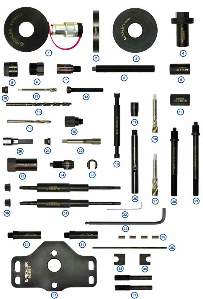
5 Injector Removal Set SOFIM / x Hydraulic Hollow Plunger Cylinder 20ton x Swivel Cup Collar x Swivel Cup x Extraction Adapter x Box Nut Adaptor x Screw-On Sleeve x Extraction Adapter External Thread M17x1/ Internal Thread M20x x Extraction Spindle M20x1.5x160mm x Twist Socket 19mm x Tap Holder Adapter Inner Square 5.7 mm / Hex x Tap M x Hexagon Socket Screw M10x75 with Full Thread / Class x Spiral Drill Ø8.5x165mm with Mark x Drill Bit Ø8.5x117mm x Drill Guide M17x x Double Pin Wrench x Centering Guide x Tap M16x x Extension Nut M20x x Allen Socket 10 with Hole x Tap Holder Adapter Inner Square 9.2mm to Hex x Tap M17x x Box Nut Adaptor x Extraction Adapter Internal Thread M14x1.5 / External Thread M20x x Open Screw x Tap Holder x Tap M18x x Extraction Spindle M18x1.5 / M20x x Extraction Spindle M16x1.5 / M20x x Collar Nut M x Outer Support Leg x Hex Key x Hex Key 8 / L=200mm x Support Leg Adapter for Inner Support Legs x Sealing Plug Ø7.2mm with Collar Ø10mm x Sealing Plug Setting Tool x Support Plate x Support Block x Inner Support Leg 5


6 A Extraction of a piëzo-controlled Bosch injector 3.0l Euro5 Remove, in preparation, all parts which are in the way such as: plastic engine cover, wiring harness at the valve cover, fuel injection lines and the injector clamp of the concerning injector. Close all resulting openings with either plugs, a piece of cloth or something similar. 1 Remove the plastic connector from the injector with a chisel or impact resistant screwdriver and a pair of pliers Slide the Open Screw on the flat spots of the injector


7 Screw Adapter on the inlet connector of the injector and tighten it. hex 10 / approx. 70Nm 7 8 Screw the Box Nut Adaptor on the Open Screw hex 32 / approx. 110Nm 9 10 Screw the Extension Nut on to the Extraction Adapter and tighten it lightly. hex


8 Screw the Extraction Spindle in the Extension Nut and tighten it. hex Continue with: Placing the support bridge Pulling process A B Page 9 Placing the support bridge 30 Pulling process 34 Injector breaks C Extraction of an torn off injector 30 Placing the support bridge 34 Pulling process Injector breaks No* Continue in case of a broken injector with step 84 Sleeve with Ø19 completely removed? Yes 26 Removing the sleeve rest Placing the support bridge Pulling process 8


9 B Extraction of a solenoid controlled Bosch injector - 2.3l Euro 4 and 5 / 3.0l Euro 4 Remove, in preparation, all parts which are in the way such as: plastic engine cover, wiring harness at the valve cover, fuel injection lines and the injector clamp of the concerning injector. Close all resulting openings with either plugs, a piece of cloth or something similar. Remove the solenoid with a slotted socket 29mm (not included in the set) or multigrip pliers. slotted socket 29mm When removing the solenoid, loose parts such as springs, washers and others may fall out. Remove the loose small parts e.g. with magnet Ø8mm (not included in the set) Unscrew the open screw with the Hex Socket and a suitable tool with a ½ square


.")


10 Pull the needle from the injector with a pair of pliers. It may happen that the needle head comes of. Then remove the rest of the needle e.g. with the magnet Ø8mm (not included in the set) Unscrew the diesel line connector from the injector and remove the sealing ring e.g. with the magnet Ø8mm (not included in the set). hex Image 27: Overview of the removed parts


11 Cut internal thread with the Tap M17x and Tap Adapter as deep as possible into the injector. hex 13 This way is also thread M17x1 cut on the small step (see picture 30) Lubricate the Tap and repeatedly break the chips Before 30 After 31 Step Remove the swarf e.g. with the magnet Ø8mm (not included in the set) or suction device (not included in the set)


12 Screw the Drill Guide in the injector and tighten it lightly. hex Clamp the Spiral Drill Ø8.5mm in a drill, wet it and insert it in the Drill Guide Drill carefully, and with repeatedly lifting, so deep into the injector until a noticeable resistance is felt, or the chuck of the drill touches the Drill Guide Remove the swarf e.g. with the magnet Ø8mm (not included in the set) or suction device (not included in the set)


13 Replace the Spiral Drill by the longer Spiral Drill with Mark Carefully continue to drill into the injector until the mark on the Spiral Drill is flush with the top of the Drill Guide Pull the drill at regular intervals far enough out of the drill guide to remove the swarf from the hole Attention: If the spiral drill was reground, the correct drilling depth is no longer consistent with the marking. The hole is deep enough when there was drilled at least 110 mm deep, measured from the top of the drill guide. (see picture 39 ) Unscrew the Drill Guide from the injector and remove the swarf e.g. with the magnet Ø8mm (not included in the set) or suction device (not included in the set)


 Should the distance exceed 21mm, repeat the")
14 Clamp the Tap M in the adapter , wet the tap with cutting oil and cut, as deep as possible, thread in the injector. Attention: Don t forget to lubricate and to break the chips. It is recommended to interrupt again and again the cutting to prevent a swarf build-up. Unscrew the Tap completely from the hole and remove the swarf e.g. with the magnet Ø8mm (not included in the set) and continue 37 the tapping until the maximum depth is reached To check whether the M10 thread has been cut deep enough, screw the Hexagon Socket Screw M10x all the way in the thread. If the distance between the areas marked in red is less than 21mm is the thread cut deep enough. (see the picture 46) Should the distance exceed 21mm, repeat the procedure from step 42. Remove the Hexagon Socket Screw M10x areas marked in red 46 Screw the Extraction Adapter in the injector and tighten it. 47 hex 24 / approx. 70Nm 48 14


15 Screw the Hexagon Socket Screw M10x through the Extraction Adapter in the previously cut thread and tighten it with Hex Key or hex socket (not included in the set). inner hex 8 / approx. 80 Nm Screw the Screw-On Sleeve all the way on the thread for the solenoid valve and tighten it lightly. hex Screw the Box Nut Adaptor on the Screw-On Sleeve and tighten it. hex 32 / approx. 90Nm


16 Screw the Extraction Spindle M20x in the Extraction Adapter and tighten it lightly. hex Continue with: Placing the support bridge Pulling process A B Page 6 Placing the support bridge 30 Pulling process 34 Injector breaks C Extraction of an torn off injector 30 Placing the support bridge 34 Pulling process Injector breaks No* Continue in case of a broken injector with step 84 Sleeve with Ø19 completely removed? Yes 26 Removing the sleeve rest Placing the support bridge Pulling process 16


17 Extraction of a piëzo controlled injector with a damaged or torn off diesel C line connecting thread Example 1 58 Example 2 59 Hammer the Twist Socket firmly on the protruding part of the injector Try to unscrew the injector counter clockwise using a socket wrench with square-drive ½ (e.g , not included in the set). Attention: First read the remarks on page
 must adapter 60385343 be welded to the injector.")

18 Remove the unscrewed part of the injector from the shaft. If during unscrewing the injector very much effort is needed can this lead to twisting or breaking of the injector. To avoid this continue on page 8 with point A, picture 5. Attention: In this case (page 7-picture 7 ) must adapter be welded to the injector. (wear safety goggles) Continue with: Extraction of an torn off injector Placing the support bridge Pulling process A B Page 6 9 Placing the support bridge 30 Pulling process 34 Injector breaks C 19 Extraction of an torn off injector 30 Placing the support bridge 34 Pulling process Injector breaks No* Continue in case of a broken injector with step 84 Sleeve with Ø19 completely removed? Yes 26 Removing the sleeve rest Placing the support bridge Pulling process 18


 from the shaft.")

19 Piëzo or solenoid-controlled injector broken or unscrewed D down in cylinder head Remove the broken upper part of the injector and support bridge. Are the Outer Support Legs already screwed in in the cylinder head, they need not be removed, unless they hamper further work. Broken injector 66 Unscrewed injector 67 Cross section of the cylinder head with broken injector Cross section of the cylinder head with unscrewed injector Remove the remaining parts e.g. with the magnet Ø8mm (not included in the set) from the shaft Cross section of the cylinder head and injector Cross section of the cylinder head and injector Determine e.g. with help of the light (not included in the set) which nozzle body is in the injector A A 70B B Cross section of the cylinder head and injector 19

 in the injector shaft and")
20 If the needle body matches type A: Use A-end of the pin wrench If the needle body matches type B: Use B-end of the pin wrench A B A B A B Spray a little rust dissolver e.g. rust remover (not included in the set) in the injector shaft and let it soak for a while

 or hex 15 (type B), release the nozzle")

. 76 77 Attention: Max. torque 20 Nm!")
.")
21 Slide the Centering Guide over the Double Pin Wrench and insert them with the right side down into the injector shaft Stick the pins of the Double Pin Wrench in the holes of the nozzle body and with an tool with hex 14 (type A) or hex 15 (type B), release the nozzle body by gently turning left & right, with max. 20 Nm. If the nozzle body can t be released with the Double Pin Wrench at max. 20Nm, it must be done in a other way using a suitable tool (Vibrohammer, hammer and chisel or by heating, etc.) Attention: Max. torque 20 Nm! Cross section of the cylinder head and injector Remove the released needle body from the shaft with a strong magnet e.g Ø12 (not included in the set) Cross section of the cylinder head and injector Remove the released needle body complete from the cylinder head. 21


22 Removing the injector sleeve Screw a Sealing Plug on the Setting Tool and close the hole to the combustion chamber Cross section of the cylinder head and injector Cross section of the cylinder head and injector Clamp the Tap M18x in the Tap Holder using Hex Key hex Slide the Centering Guide on to the Tap Holder , wet the Tap with grease or cutting oil and insert it in the injector shaft


.")
23 Cut with a suitable tool M18x1.5 thread in the still stuck sleeve. hex Cross section of the cylinder head and injector Cut the thread over the full length of the injector sleeve and repeatedly break the chips. 88 It is recommended after cutting thread in the sleeve, to remove the chips and to repeat the cutting. Cross section of the cylinder head and injector Remove the swarf e.g. with the magnet Ø8mm (not included in the set) or suction device (not included in the set). Attention: The Sealing Plug must not be removed along Cross section of the cylinder head and injector 23


24 Screw the Extraction Spindle in the previously cut thread and tighten it. hex Cross section of the cylinder head and injector Screw the Extension Nut on the Extraction Spindle and tighten it lightly. hex Screw the Extraction Spindle M20x in the Extension Nut and tighten it lightly. hex
25 Continue with: Placing the support bridge Pulling process A Placing the support bridge Pulling process B Injector breaks C Extraction of an torn off injector 30 Placing the support bridge 34 Pulling process Injector breaks No* Continue in case of a broken injector with step 84 Sleeve with Ø19 completely removed? Yes 26 Removing the sleeve rest Placing the support bridge Pulling process 25
 is still stuck in the injector shaft, repeat the steps from broken injector from step 84 on page 24.")
26 First must be determined, how much of the lower threaded sleeve is still stuck in the injector shaft. This can be found out by comparing the removed part with a new injector. If a rest of the larger diameter (19mm) is still stuck in the injector shaft, repeat the steps from broken injector from step 84 on page 24. C sleeve with outer diameter 19mm Ø17 Ø19 Threaded part of the new injector still stuck in the injector shaft is removed A Example: The injector was unscrewed in the lower part still stuck in the injector shaft is removed A Example: The injector is broken flush beneath the thread B Was only a part (A) removed from the shaft, the remaining part of the sleeve (B) must still be removed. Repeat the steps from 84 on page 24. possible points of breakage The removed pieces should be compared with a new injector. Only after the entire sleeve with outer diameter 19mm is removed completely can be continued with the next step, because the M16x1.5 thread in the thinner sleeve with outer diameter 17mm is not strong enough for also removing even the smallest part with outer diameter 19mm. C Threaded part of the new injector Parts (A) and (B) are together the total length of the sleeve with outer diameter 19mm (C) B A B A Example: The injector was unscrewed in the lower part Example: The injector is broken flush beneath the thread


27 Removing the sleeve rest with outer diameter 17mm Clamp the Tap M16x in the Tap Holder with Hex Key hex Slide the Centering Guide on to the Tap Holder , wet the Tap with grease or cutting oil Cut with a suitable tool M16x1.5 thread in the stuck sleeve hex Cross section of the cylinder head and injector 27


28 Cut thread over the full depth of the injector sleeve and repeatedly break the chips. 104 It is recommended after cutting thread in the sleeve, to remove the chips and to repeat the cutting. Cross section of the cylinder head and injector Remove the swarf using a magnet or suction device Cross section of the cylinder head and injector Insert the Extraction Spindle in the injector shaft and screw it as far as it goes into the previously cut thread and tighten it. hex Cross section of the cylinder head and injector 28


29 Screw the Extension Nut on the Extraction Spindle and tighten it lightly. hex Screw the Extraction Spindle into the Extension Nut M20x and tighten it lightly. hex Continue with: Placing the support bridge Pulling process A Placing the support bridge Pulling process B Injector breaks C Extraction of an torn off injector Placing the support bridge Pulling process Injector breaks No* Continue in case of a broken injector with step 84 Sleeve with Ø19 completely removed? Yes Removing the sleeve rest Placing the support bridge Pulling process 29


30 E Placing the support bridge over the various cylinders Unscrew the corresponding valve cover bolts of the concerning injector according the picture Cylinder 1 Cylinder 2 Cylinder 3 Cylinder 4 Screw both Outer Support Legs in the holes of the removed valve cover bolts and tighten them. hex


 is used as other support. (picture 119 ).")
31 The two Support Blocks are always placed on the camshaft cover over the screws so that the front side without cut out always points in the direction of the concerning injector. e.g. with cylinder 2 (picture 117 ) Attention: Only 1 Support Block is used on the 4th cylinder. The pin on the camshaft cover (counter support for the injector clamp) is used as other support. (picture 119 ). 116 Cylinder Screw the two Inner Support Legs all the way in the Support Leg Adapter


32 122 Attention: The wider flat part of the Support Plate must point in the direction of the timing belt or chain, for each of the four cylinders. timing wider flat part Place the Support Plate on the Outer Support Legs and fix it with the two M10 Collar Nuts in such a way that the plate can still be positioned. Must always point in the direction of the valve control Align the Support Plate , so that the two Inner Support Legs are located over the two support blocks. The Extraction Spindle must not touch the Support Plate Attention: With cylinder 4 must one Inner Support Leg , be positioned over the pin on the camshaft cover as shown in pictures 127 &


 Tighten both Inner Support Legs")
33 Hold the support bridge and tighten the two Collar Nuts M with a spanner. hex Screw the Inner Support Legs with the Hex Key so far out until they make light contact with the support blocks hex 8 Attention: With cylinder 4 must one Inner Support Leg , rest on the pin on the camshaft cover (counter support for the injector retaining fork). (picture 133 ) Tighten both Inner Support Legs alternately till these are well-set on the Support Blocks hex


34 Place the Swivel Cup Collar and Swivel Cup over the Extraction Spindle on the Support Plate It is important to ensure that the arrows on the Swivel Cup Collar point down of the Support Plate or cylinder head! in the direction Bleeding the hydraulic system Example: hydraulic pump with hose Bleed screw Connected hydraulic Hollow Plunger Cylinder 20t to the hydraulic pump. Place the Hollow Plunger Cylinder lower than the hydraulic pump so that the air can rise through the hose to the hydraulic pump. Build up pressure till the max. stroke of Hollow Plunger Cylinder is reached. Relieve the pressure by opening the relief valve. Repeat his procedure 4 to 5 times. Top up the oil if necessary. Connection must point upwards Example: Hydraulic Hollow Plunger Cylinder 20t F Extraction process Place the Hydraulic-Hollow Plunger Cylinder 20t over the Extraction Spindle on the Swivel Cup. Screw the Extraction Adapter on the Extraction Spindle and centre the Cylinder with the Swivel Cup Collar and Swivel Cup


35 Build up only low pressure for 2 to 3 times at the beginning of the extraction procedure, relieve the pressure and tighten the Extraction Adapter. This allows the support bridge with the other components to align and thereby settle somewhat. Start the extraction procedure, after about 8mm the maximum stroke of the Hydraulic Cylinder is reached. Release the pressure, screw in the Adapter and again build up the pressure. Attention: Upon reaching 8mm lift height do not continue to pump, but relieve the pressure, screw in the Adapter and re-apply the pressure. Repeat the procedure until the injector is extracted Piëzo-controlled Bosch injector completely removed Solenoid valve controlled Bosch injector completely removed When the injector breaks in the lower part during the extraction process then continue on page 21. When the injector breaks during the extraction process and can the nozzle body and the injector sleeve be removed, continue on Page Piëzo-controlled Bosch injector broken off Solenoid valve controlled Bosch injector broken off 35


36 Recommended accessories Hydraulic Set 3 pieces Air Hydraulic Foot Pump Set, 3-pcs 700 bar Rust Loosener and Contact Spray 400 ml Pneumatic hammer set Vibro-Impact with 4 adapters Flexible magnet Gr mm long - Ø 8,0 mm Gr mm long - Ø 12,0 mm


37 Flexible lamp BAL 410mm long tip Ø3,2mm Injector Socket 29 Drive 1/ Universal ratchet lever, drive 1/2 ratchet head, 670mm long Injector Shaft Cleaning Set complete Cutting Grease 300g For optimal cleaning and revision of the injector shaft. Content: Basic Module - plastic case with insert Module 1 - Brushes Module Brushes Plus Module 2 - Milling Module 3 - Equipment


38 AUSTRIA PICHLER Werkzeug GmbH & CoKG Pacherstrasse 20 A-6023 Innsbruck GERMANY PICHLER Werkzeug GmbH Zugspitzstrasse 33 D Garmisch-Partenkirchen SWITZERLAND PICHLER Werkzeug AG Rünenbergerstrasse 31 CH-4460 Gelterkinden FRANCE PICHLER Outillage Sàrl 19a, rue de Reiningue F Wittelsheim BELGIUM PICHLER Outillage BVBA Industrieweg 45 B-8800 Roeselare GREAT BRITAIN & IRELAND PICHLER TOOLS LTD Ednaston Business Centre Hollington Lane, Ednaston Ashbourne DE6 3AE Stand: 11/2014 Version:
INJECTOR REMOVAL SET M9R/M9T/R9M &
 MANUAL INJECTOR REMOVAL SET M9R/M9T/R9M 60382095 & 60382190 SUPPLEMENTARY KITS 60382105 60382115 60382120 60382125 60382135 60382200 Built to succeed. Version 1.0 60382095 & 60382190 INJECTOR REMOVAL SET
Injector Extraction Kit for the M9R / M9T
 Work Instructions Injector Extraction Kit for the M9R / M9T 60385095 Tensile Force Limiter 60385229 page 1 of 40 page 2 of 40 Safety notice Important! Be sure to read these instructions before assembling,
Universal Injector Removal Tool Kit
 Manual Universal Injector Removal Tool Kit for Bosch, Siemens, Denso and Delphi CR injectors 60384435 / 60384535 SAFETY NOTICE To understand the functioning of the tools, is it necessary to read the manual
PSA DV6 / Ford DLD-416 Injector sleeve tool/ kit
 Work Instructions PSA DV6 / Ford DLD-416 Injector sleeve tool/ kit 60385420 Ford Focus II (DA_, DAW_, C-MAX), Fiesta V/ Fusion (JH_, JD_JU), 1.6 Duratorq-TDCi (66kW) HHDA, HHDB, HHJA, HHJB Focus II (DA_,
TECHNICAL INFORMATION
 TECHNICAL INFORMATION Model No. Description HR3200C, HR3210C, HR3210FCT Rotary Hammer 32mm (1-1/4") CONCEPT AND MAIN APPLICATIONS HR3200C series models have been developed as successor models of HR3000C,
Installation Instructions COMPETITION/PLUS SHIFTER Ford Mustang MT82 6-Speed Manual Transmission Catalog#
 Installation Instructions COMPETITION/PLUS SHIFTER 2015-2017 Ford Mustang MT82 6-Speed Manual Transmission Catalog# 3916037 Rev. 00 WORK SAFELY! For maximum safety, perform this installation on a clean,
Installation Manual TWM Performance Short Shifter Cobalt SS/SC, SS/TC, HHR SS, Ion Redline and Saab 9-3
 Page 1 Installation Manual TWM Performance Short Shifter Cobalt SS/SC, SS/TC, HHR SS, Ion Redline and Saab 9-3 Please Note: It is preferable to park on a flat surface, as you will have to engage and disengage
#TL T EA888 GEN 3 FUELING SYSTEM/ INSTALLATION INSTRUCTIONS
 #TL100069 2.0T EA888 GEN 3 FUELING SYSTEM/ INSTALLATION INSTRUCTIONS Notes: These instructions were written for a North American specification MkVII GTI. Other models, like the Golf R, are similar. When
DIESEL FUEL Click on the applicable bookmark to selected the required model year
 DIESEL FUEL 13E-2 DIESEL FUEL General Information/Service Specifications/ Special Tool/On-vehicle Service GENERAL INFORMATION 13300010025 The fuel is drawn out of the fuel tank by means of the feed pump
TECHNICAL INFORMATION
 TECHNICAL INFORMATION Model No. Description CONCEPT AND MAIN APPLICATIONS Specification HR2800, HR2810, HR2811F HR2810T, HR2811FT Rotary Hammers 28mm (1-1/8") HR2800 series models have been developed as
Installation Manual TWM Performance Short throw shifter 2001 and up Hyundai Accent
 Installation Manual TWM Performance Short throw shifter 2001 and up Hyundai Accent 1. Place the vehicle on a flat surface with blocks in front and behind the wheels preventing unwanted movement. The car
Sachs shock manual. ( ) 2 & 4 Stroke RR Enduro. ( ) RS Dual Sport
 2 & 4 Stroke RR Enduro. ( ) RS Dual Sport") Sachs shock manual (2013 2015) 2 & 4 Stroke RR Enduro (2014-2015) RS Dual Sport 1 Introduction The procedures in this manual must take place in a clean environment using professional tools and some specific,
Sachs shock manual (2013 2015) 2 & 4 Stroke RR Enduro (2014-2015) RS Dual Sport 1 Introduction The procedures in this manual must take place in a clean environment using professional tools and some specific,
INSTALLATION AND MAINTENANCE OF TOP LOADING ARM
 INSTALLATION AND MAINTENANCE OF TOP LOADING ARM D TABLE OF CONTENTS 1. INTRODUCTION 04 2. SPECIFICATION OF THE REDLANDS LOADING ARM 04 3. INSTALLING THE LOADING ARM 3.1. Installation Procedures 05 4.
Service Handbook. High-Pressure Washer Pump
 Pump 629 9/28/01 3:22 PM Page 1 Service Handbook High-Pressure Washer Pump 3.532-629.0 10.00 Pump 629 9/28/01 3:22 PM Page 2 Pump 629 9/28/01 3:22 PM Page 3 TROUBLESHOOTING OVERVIEW How to Use This Manual
Maintenance Information
 16573321 Edition 3 February 2014 Air Grinder Series 61H Maintenance Information Save These Instructions Product Safety Information WARNING Failure to observe the following warnings, and to avoid these
Sisu S-Cam Drum Brakes
 Sisu S-Cam Drum Brakes (For hub reduction rear axles since 1992) Maintenance Manual Sisu Axles, Inc. Autotehtaantie 1 P.O. Box 189 FIN-13101 Hämeenlinna Finland Phone int + 358 204 55 2999 Fax int + 358
SERVICE PARTS LIST 1-1/8" ROTARY HAMMER MILWAUKEE ELECTRIC TOOL CORPORATION W. LISBON RD., BROOKFIELD, WI Drwg.
 00 0 200 204 276 EXAMPLE: Component Parts (Small #) Are Included When Ordering The Assembly (Large #). SERVICE PARTS LIST SPECIFY CATALOG NO. AND SERIAL NO. WHEN ORDERING PARTS PAGE 1 OF 3 BULLETIN NO.
TECHNICAL INFORMATION
 TECHNICAL INFORMATION Model No. Description GA5020C/GA6020C, GA5021C/GA6021C Angle Grinders 125mm (5") /150mm (6") L PRODUCT P 1/10 CONCEPT AND MAIN APPLICATIONS These four models have been developed as
INSTALLATION INSTRUCTIONS RATTLER STEEL RUNNING BOARDS FORD TRANSIT VAN (FULL SIZE)
") INSTALLATION INSTRUCTIONS PARTS LIST: 1 32-inch Steel Running Board 1 8-1.25mm x 35mm Hex Bolt 1 96-inch Steel Running Board 13 8-1.25mm x 25mm Hex Bolt 5 Passenger Side/Driver Side Mounting Brackets 20
INSTALLATION INSTRUCTIONS PARTS LIST: 1 32-inch Steel Running Board 1 8-1.25mm x 35mm Hex Bolt 1 96-inch Steel Running Board 13 8-1.25mm x 25mm Hex Bolt 5 Passenger Side/Driver Side Mounting Brackets 20
Suzuki GS1000G fork seal replacement
 Suzuki GS1000G fork seal replacement Before you start you require: 1) To read workshop service manual for your model 2) Socket allen key M8 3) Torque wrench 4) Special tool to hold inner, make your own,
Maintenance Information
 16575243 Edition 2 October 2013 Air Screwdrivers 1R Series Maintenance Information Save These Instructions Product Safety Information WARNING Failure to observe the following warnings, and to avoid these
TECHNICAL INFORMATION
 TECHNICAL INFORMATION PRODUCT P 1 / 15 Model No. Description HR2455 Rotary Hammer 24mm (15/16") L W CONCEPT AND MAIN APPLICATIONS Model HR2455 has been developed as a sister tool to Model HR2450, the Makita
VECTRIX VX-2 SERVICE MANUAL. Version 1.0/May 2011 VECTRIX, LLC
 www.vectrix.com CONTENTS SECTION A: Tools 1 Tools Needed SECTION B: Mechanical Parts 1 Front Fairing 2 Front Console Cover 3 Speedometer Cover 4 Front Vertical Panel Cover-Lower 5 Front Vertical Panel
Dismantling and assembling transmission
 27-640 Dismantling and assembling transmission Operation number of the operation texts and work units or standard texts and flat rates: 27-4010 P27-5367-61 Control pressure cable (98) Slacken, remove and
9/24/2017 Camshaft Timing Chain Removal and Installation Engine Mechanical 2002 Audi A6/S6/Quattro/Allroad MotoLogic
 2002 A6/S6/Quattro/Allroad The information in this article comes from a service manual containing information that applies to the following engine code: BAS. Section Info: Report a problem with this article
Maintenance Information
 Form 16573321 Edition 1 July 2004 Air Grinder Series 61H Maintenance Information Save These Instructions Always wear eye protection when operating or performing maintenance on this tool. Always turn off
SLM - Sealing Liquid Monitor INSTRUCTIONS FOR USE
 INSTRUCTIONS FOR USE 1/8 1 INSTALLATION SLM - Sealing Liquid Monitor INSTRUCTIONS FOR USE 1.1 Mounting The SLM has a mounting plate for simple installation. The SML can be mounted using a bolt already
ORIGA SYSTEM PLUS Guides, Brakes and Valves for Modular Linear Drive Systems OSP Appendix to the Operating Instructions
 ORIGA SYSTEM PLUS Guides, Brakes and Valves for Modular Linear Drive Systems OSP Appendix to the Operating Instructions TAll personnel who have anything to do with the OSP fitted with guides, brakes or
Installation Instructions for disc brakes
 Installation Instructions for disc brakes Bedford CF 230-280, built 1974-1986, not suitable for vehicles with rear twin tyres Included 2 pcs. Wheel Hubs with Wheel Bolts, Mounted Brake Discs and Wheel
Maintenance Information
 16573370 Edition 2 February 2014 Air Grinder 99V Series Maintenance Information Save These Instructions Product Safety Information WARNING Failure to observe the following warnings, and to avoid these
Drive unit. Installing/removing ebike components. Tool: Allen key size 8. ISIS crank-puller. Spider-Tool. Lever (e.g.
 Removing the chain wheel Remove the crank arms (Allen key size 8, ISIS crank-puller). Block the rear wheel. Tip: Clamp the brake lever with Velcro. Unscrew the lock ring () with the Spider-Tool (). Caution:
SUBJECT: INTEGRATED FUEL SYSTEM (IFS) UNIT PUMP SERVICE
 UNIT PUMP SERVICE") DATE: July 30, 2010 SERVICE BULLETIN SUPERSEDES: S.B. 560 dated November 22, 2008 NO: 560R1 SUBJECT: INTEGRATED FUEL SYSTEM (IFS) UNIT PUMP SERVICE RELATED PUBLICATIONS: IFS OPERATION AND INSTRUCTION MANUAL
DATE: July 30, 2010 SERVICE BULLETIN SUPERSEDES: S.B. 560 dated November 22, 2008 NO: 560R1 SUBJECT: INTEGRATED FUEL SYSTEM (IFS) UNIT PUMP SERVICE RELATED PUBLICATIONS: IFS OPERATION AND INSTRUCTION MANUAL
InstalL Instructions. trail-creeper 4.70 transfer case gear kit ( KIT and KIT) kit contents
 kit contents") InstalL Instructions trail-creeper 4.70 transfer case gear kit (105000-1-KIT and 105001-1-KIT) kit contents 5356 PINE AVE FRESNO, CA 93727 USA TOLL FREE: 877.4X4.TOYS WORLDWIDE: 559.252.4950 WWW.TRAIL-GEAR.COM
InstalL Instructions trail-creeper 4.70 transfer case gear kit (105000-1-KIT and 105001-1-KIT) kit contents 5356 PINE AVE FRESNO, CA 93727 USA TOLL FREE: 877.4X4.TOYS WORLDWIDE: 559.252.4950 WWW.TRAIL-GEAR.COM
WARNING: ALWAYS relieve fuel pressure before disconnecting any fuel related component. DO NOT allow fuel to contact engine or electrical components.
 4.0L V8 - VINS [K,U] Selected Block 1990 Lexus LS 400 For Lextreme Powertrain 2020 S. Hacienda Blvd. # D Hacienda Heights California 91745 Copyright 1998 Mitchell Repair Information Company, LLC Friday,
Super T QR20 INSTRUCTIONS GENERAL RULES
 INSTRUCTIONS GENERAL RULES 1. Where specified, assemble and disassemble the shock absorption system using the MARZOCCHI special tools only. 2. On reassembling the suspension system, always use new seals.
Maintenance Information
 04581245 Edition 2 May 2014 Air Grinder, Die Grinder and Sander Series G2 (Angle) Maintenance Information Save These Instructions Product Safety Information WARNING Failure to observe the following warnings,
TECHNICAL INFORMATION
 TECHNICAL INFORMATION Models No. Description BHR202 Cordless Combination Hammer CONCEPT AND MAIN APPLICATIONS The subject model features 18V Li-ion Battery and 3 mode selection for ensuring an operator
AmTryke Adult Recumbent Model HP1000 #50-HC-1000
 AmTryke Adult Recumbent Model HP1000 #50-HC-1000 TOOLS Needed for Assembly 5 mm Allen Wrench 8 mm Socket or Wrench 10 mm Socket or Wrench 14 mm Socket or Wrench 15 mm Socket or Wrench 22 mm Socket or Adjustable
Replace front brake pads and discs * (Ford Galaxy )
") Replace front brake pads and discs * (Ford Galaxy 2006-2015) *Caution! This instructions are created by random users and must be used as a reference only! Please, take all safety precautions, and if you're
Replace front brake pads and discs * (Ford Galaxy 2006-2015) *Caution! This instructions are created by random users and must be used as a reference only! Please, take all safety precautions, and if you're
Repairing the CIS Jetronic Alloy adjustable Bosch Fuel distributor
 CIS-Jetronic.com 07.3-0997-06-01 Repairing the CIS Jetronic Alloy adjustable Bosch Fuel distributor When do you have to repair your CIS Bosch fuel distributor? If your car has rough idle, low power, high
EasySelect-Cup Manual Powder Gun
 E Operating Instructions and Spare parts list EasySelect-Cup Manual Powder Gun EasySelect-Cup 27 28 EasySelect-Cup Table of Contents Safety rules EasySelect-Cup Manual Powder gun...........................................
Volkswagen New Beetle 2.0 Liter 4-cyl General, Engine (Engine Code AEG) 13 Engine-Crankshaft, Cylinder block (Page GR-13)
 13 Engine-Crankshaft, Cylinder block (Page GR-13)") 13 Engine-Crankshaft, Cylinder block (Page GR-13) Engine, disassembly and assembly 10-222 A/21 guide from 10-222 A support tool, modifying Ribbed belt, removing and installing Semi-automatic toothed belt
13 Engine-Crankshaft, Cylinder block (Page GR-13) Engine, disassembly and assembly 10-222 A/21 guide from 10-222 A support tool, modifying Ribbed belt, removing and installing Semi-automatic toothed belt
TECHNICAL INFORMATION
 TECHNICAL INFORMATION Model No. Description DP4010, DP4011 2-Speed Drill 13mm (1/2") L PRODUCT P 1/ 8 CONCEPT AND MAIN APPLICATIONS Models DP4010 and DP4011 have been developed as 13mm (1/2") Drill for
SERVICE INSTRUCTIONS D TON
 1120 SOUTH CRYSTAL AVE * BENTON HARBOR MI PH: 269-925-7777 FAX: 269-925-6656 SERVICE INSTRUCTIONS D-51223 4 TON TO ASSEMBLE: 1. Check the handle set screw for tightness. CUSTOMER PRE-USE INSTRUCTIONS THE
Property of American Airlines
 Date Maintenance Check list This document describes the inspection and maintenance of the Power Stow Rollertrack. Maintenance refers to a time span. The operation hours are shown on the Power Stow Display
Workshop manual 4618 BAVP 85 SX. Product Exploded View Disassembly & Assembling. Schok absorber 4618 BAVP 85 SX
 Schok absorber Introduction 2 Exploded view 3 Disassembly shock absorber 4 Disassembly piston rod 12 Assembling piston rod 23 Disassembly adaptor DU-bush 33 Assembling adaptor DU-bush 36 Disassembly tube
Installation Instructions INDY SHIFTER Fits: Mustang Fastback & Convertible with MT-82 Transmission Catalog #
 Installation Instructions INDY SHIFTER Fits: 2015-2018 Mustang Fastback & Convertible with MT-82 Transmission Catalog # 3916036 Watch our installation video on YouTube WORK SAFELY! For maximum safety,
Property of American Airlines
 Date Maintenance Check list The inspection and preventive maintenance schedule of the Power Stow Rollertrack is as follows: Daily (10 hrs), Weekly (50 hrs.), every 6 months ( hrs.), yearly (1 hrs.) and
OIL COOLER KIT INSTALLATION INSTRUCTIONS PART NUMBER D E92 335i/xi (N55 engine) with M-Technic bumper and without stock oil cooler
 with M-Technic bumper and without stock oil cooler") OIL COOLER KIT INSTALLATION INSTRUCTIONS PART NUMBER D570-0925 APPLICATION 2011-12 E92 335i/xi (N55 engine) with M-Technic bumper and without stock oil cooler Congratulations for being selective enough
OIL COOLER KIT INSTALLATION INSTRUCTIONS PART NUMBER D570-0925 APPLICATION 2011-12 E92 335i/xi (N55 engine) with M-Technic bumper and without stock oil cooler Congratulations for being selective enough
Suzuki Samurai to Toyota Front Spring Swap Kit, with Missing Link Shackles (SKU#SSP-TSFM) Installation Instructions
 Installation Instructions") Suzuki Samurai to Toyota Front Spring Swap Kit, with Missing Link Shackles (SKU#SSP-TSFM) Installation Instructions CAUTION: Safety glasses should be worn at all times when working with vehicles and related
Suzuki Samurai to Toyota Front Spring Swap Kit, with Missing Link Shackles (SKU#SSP-TSFM) Installation Instructions CAUTION: Safety glasses should be worn at all times when working with vehicles and related
CALIFORNIA TRIMMER MOWER MAINTENANCE MANUAL
 CALIFORNIA TRIMMER MOWER MAINTENANCE MANUAL 2 Table of Contents Section 1: General Information Page Handle Assembly Instructions 4 Maintenance All Models 6 Oil Change Procedures All Models 9 Height Adjustment
FOR FUTURE REFERENCE SERIES 93HPS
 Hypro Series 93HPS Hydraulically Driven Wetseal Multistage Pumps Repair Manual KEEP FOR FUTURE REFERENCE Form L-1578R Rev. A SERIES 93HPS Hydraulically Driven Stainless Steel Multistage Centrifugal Pumps
A Quick reference guide to the installation of Uniflex. Oldham Seals Group. Uniflex installation Guide
 A Quick reference guide to the installation of Uniflex. Oldham Seals Group Uniflex installation Guide Uniflex Guide From Oldham Seals Group Introduction: Uniflex systems provide a means of remote Valve
KIT TOOLS MANUAL For Engine Assembly
 KIT TOOLS MANUAL For Engine Assembly Preface This manual provides motorcycle teams with clear information on a line of tools that simplify basic tuning. We believe that these tools make engine tuning accessible
MUELLER GAS. Shur StopTM Unit 812 PE Line Stopping. System 8" 12" SDR Reliable Connections. General Information 2
 operating Instructions manual MUELLER GAS TAble of contents PAGE TM Unit 812 PE Line Stopping General Information 2 Equipment, Parts and Dimensions 3-5 Operating Instructions 6-12 Troubleshooting and Storage
OIL COOLER KIT INSTALLATION INSTRUCTIONS PART NUMBER D E92 335i/xi (N55 engine) with BMW Standard bumper and with stock oil cooler
 with BMW Standard bumper and with stock oil cooler") OIL COOLER KIT INSTALLATION INSTRUCTIONS PART NUMBER D570-0924 APPLICATION: 2011-12 E92 335i/xi (N55 engine) with BMW Standard bumper and with stock oil cooler Congratulations for being selective enough
OIL COOLER KIT INSTALLATION INSTRUCTIONS PART NUMBER D570-0924 APPLICATION: 2011-12 E92 335i/xi (N55 engine) with BMW Standard bumper and with stock oil cooler Congratulations for being selective enough
Installation Manual TWM Performance Short Shift Kit Stage 1 and Stage 2 MazdaSpeed 6
 Page 1 Installation Manual TWM Performance Short Shift Kit Stage 1 and Stage 2 MazdaSpeed 6 Please Note: It is preferable to park on a flat surface, as you will have to engage and disengage the hand brake
CorkSport ort Mazda 3 Adjustable Shifter Mazdaspeed 3, Mazda 3 6-speed and Mazda3 SkyActiv 6-speed
 Part # Axl-6-963 CorkSport ort Mazda 3 Adjustable Shifter 2010-2013 Mazdaspeed 3, 2010-2013 Mazda 3 6-speed and 2012-2013 Mazda3 SkyActiv 6-speed Pre-Installation Notes: The CorkSport Adjustable Short
NOTE: Visit our website at for video repair procedures, under the Tools section.
 Repair Instructions Hypro Repair Tools: Tool Box No. 3010-0168 1/4" Allen Wrench No. 3020-0008 Support Bars (2) No. 3010-0064 Port Brush No. 3010-0066 1/16" Allen Wrench No. 3020-0009 Brush Holder No.
TECHNICAL INFORMATION Model No. Description
 TECHNICAL INFORMATION Model No. Description 4114, 4114S Angle Cutter 355mm (14") PRODUCT P 1 / 6 CONCEPT AND MAIN APPLICATIONS Model 4114S is the 355mm (14") version of the current 4112S 305mm (12") Angle
OIL COOLER KIT INSTALLATION INSTRUCTIONS PART NUMBER D
 OIL COOLER KIT INSTALLATION INSTRUCTIONS PART NUMBER D570-0904 APPLICATION: 2011-2012 E90 335i/xi (N55 engine) with BMW standard bumper and with stock oil cooler Congratulations for being selective enough
BOSCH VE 250 INJECTION PUMP
 1.0 BOSCH VE 250 DIESEL INJECTION PUMP Land Rover fit the Bosch VE-type rotary distributor diesel injection pump onto their 300 TDI engines. Two main variants were installed: the standard models were fit
Repair Manual 11/99 PS-34. Page 1
 Repair Manual /99 PS-4 Page Table of contents Index Technical Data page Special tools 4 Repair instructions, general 0 Chain brake 6 0 Centrifugal clutch 8 0 Oil pump 9-04 Ignition system - 0 Starting
Valvetrain, servicing
 Page 1 of 51 15-32 Valvetrain, servicing Note: Cylinder heads with small cracks between the valve seats that are less than 0.3 mm (0.012 in.) wide and/or between one valve seat and only the first 4 threads
Disassembly. 1 Pull off the QUIK-LOK cable from the machine.
 Special Tools Require Important! Torx TX0 bit 0 0 Screwdriver Torx 0 0 0 Forcing Discs 0 Before beginning the maintenance work, perform an initial check with a high voltage test according to VDE (see chapter
Copper Sleeve, Unit Injector, Replacement
 Volvo Trucks North America Greensboro, NC USA This service bulletin replaces SB 237-46, Copper Sleeve, Unit Injector, Replacement dated 6.2007, publication no. PV776-20177417. DService Bulletin Trucks
OIL COOLER KIT INSTALLATION INSTRUCTIONS PART NUMBER D E92 335is (N54 engine) with BMW M-Technic bumper and with stock oil cooler
 with BMW M-Technic bumper and with stock oil cooler") OIL COOLER KIT INSTALLATION INSTRUCTIONS PART NUMBER D570-0923 APPLICATION: 2011 E92 335is (N54 engine) with BMW M-Technic bumper and with stock oil cooler Congratulations for being selective enough to
OIL COOLER KIT INSTALLATION INSTRUCTIONS PART NUMBER D570-0923 APPLICATION: 2011 E92 335is (N54 engine) with BMW M-Technic bumper and with stock oil cooler Congratulations for being selective enough to
Z TECHNICAL INSTRUCTIONS
 ÍNDICE: Z40 2.0 TECHNICAL INSTRUCTIONS 1.- Error list 2.- Replace the control board 3.- Opening the machine 4.- Replace the power board 5.- Dismantling motor and gear box 6.- Assembly of gear box 7.- Pushing
Micro-Injection System
 QUIK-- Micro-Injection System Table of Contents Part 1: Getting Started & Using your QUIK-jet Air Parts of the QUIK-jet Air Device...2 Parts of the QUIK-jet Air Kit...3 Air Tank Assembly...4 Connecting
Subaru 5-Speed Double Adjustable Short Throw Shifter
 Subaru 5-Speed Double Adjustable Short Throw Shifter 1999+ Subaru Impreza 5-Speed 2004-2005 Subaru Forester XT 5-Speed Congratulations on your purchase of the COBB Tuning Double Adjustable Short Throw
TECHNICAL INFORMATION
 TECHNICAL INFORMATION Model No. Description CONCEPT AND MAIN APPLICATIONS Specification GA4030, GA4530, GA5030 Angle Grinders 100mm (4"), 115mm (4-1/2"), 125mm (5") GA4030/ GA4530/ GA5030 are small diameter
AmTryke Adult Recumbent Model JT2000 #50-FC-2000
 AmTryke Adult Recumbent Model JT2000 #50-FC-2000 TOOLS Needed for Assembly 5 mm Allen Wrench 8 mm Socket or Wrench 10 mm Socket or Wrench 14 mm Socket or Wrench 15 mm Socket or Wrench 22 mm Socket or Adjustable
N63 Valve Stem Seal Tool Kit Part #: AGA-N63-VSK-K
 N63 Valve Stem Seal Tool Kit Part #: AGA-N63-VSK-K Problem: Your BMW is smoking due to bad valve stem seals. Old valve stem seals harden over time and no longer provide a proper seal between the seal and
Oil Drain Plug Repair Kit. 5. Boring tool (drill bit) 1. Oil cap with regulator. 6. Alignment tool. 2.
 1. Oil cap with regulator. 6. Alignment tool. 2.") Oil Drain Plug Repair Kit Part #: AGA-ODP-12-14-K 1. Oil cap with regulator 2. Oil drain plugs 3. Air supply hose with valve 4. Debris shield 5. Boring tool (drill bit) 6. Alignment tool 7. Thread forming
Oil Drain Plug Repair Kit Part #: AGA-ODP-12-14-K 1. Oil cap with regulator 2. Oil drain plugs 3. Air supply hose with valve 4. Debris shield 5. Boring tool (drill bit) 6. Alignment tool 7. Thread forming
Volkswagen New Beetle Body - Exterior 64 Glass, Window regulators (Page GR-64)
") 64 Glass, Window regulators (Page GR-64) Flush bonded windows Body flange, preparing for glass installation Broken rear window, removing Cleaning off excess adhesive material Curing time Installation instructions
64 Glass, Window regulators (Page GR-64) Flush bonded windows Body flange, preparing for glass installation Broken rear window, removing Cleaning off excess adhesive material Curing time Installation instructions
Volkswagen New Beetle 1.8 Liter 4-Cyl. 5V Turbo OBD II Engine Mechanical 17 Engine-Lubrication system (Page GR-17)
") 17 Engine-Lubrication system (Page GR-17) Lubrication system components, removing and installing Oil pressure and oil pressure switch, checking Sump, removing and installing Valve gear, servicing (Page
17 Engine-Lubrication system (Page GR-17) Lubrication system components, removing and installing Oil pressure and oil pressure switch, checking Sump, removing and installing Valve gear, servicing (Page
Steering Damper MX SD 2.1. Workshop Manual
 Steering Damper MX SD 2.1 Workshop Manual Safety Precautions Before you begin Warning! Öhlins Racing AB can not be held responsible for any damage to the Steering Damper, vehicle, other property or injury
INSTALLATION GUIDE. Kawasaki KLR Manual Revision:
 REKLUSE MOTOR SPORTS The z-start Pro Clutch INSTALLATION GUIDE Kawasaki KLR650 191-640 Manual Revision: 030308 2007 Rekluse Motor Sports Rekluse Motor Sports, Inc. 110 E. 43rd Street Boise, Idaho 83714
Safety, Operation and Maintenance Instructions For Long & Short Nose Upholstery Air Stapler (NS10 & NS11)
") Safety, Operation and Maintenance Instructions For Long & Short Nose Upholstery Air Stapler (NS10 & NS11) Important: Drop 3 drops of oil into the stapler air inlet BEFORE first use. See page 2. Please
Safety, Operation and Maintenance Instructions For Long & Short Nose Upholstery Air Stapler (NS10 & NS11) Important: Drop 3 drops of oil into the stapler air inlet BEFORE first use. See page 2. Please
Installation Instructions
 Preparing your vehicle to install your brake system upgrade 1. Rack the vehicle. 2. If you don t have a rack, then you must take extra safety precautions. 3. Choose a firmly packed and level ground to
Installation instruction do88 Intercooler for SAAB 9-3SS/SC 4-cyl Turbo
 Installation instruction do88 Intercooler for SAAB 9-3SS/SC 4-cyl Turbo This instruction shows how to replace the OEM intercooler with this performance intercooler. 1. 4. 5. At this type of installation
TECHNICAL INFORMATION Model No. Description
 TECHNICAL INFORMATION Model No. Description CONCEPT AND MAIN APPLICATIONS Specification HR2450, HR2451, HR2452 24mm (15/16 " ) Rotary Hammer The above models are the advanced version of MAKITA's famous
Wheel Bearing Replacement Passat TDI
 Rear Bearing/hub assembly replacement This is a fairly straight forward process. Pictures are not necessary for most of this procedure for a person with skills to do this repair. Anyone who thinks they
INSTALLATION GUIDE Manual Revision:
 REKLUSE MOTOR SPORTS The z-start Pro Clutch INSTALLATION GUIDE KTM 125, 144, 200 2-Stroke KTM 250, 300 2-Stroke KTM 250 SXF, XC, XC-W KTM 400 XC-W KTM 450, 505 SXF, XC-F KTM 450, 530 XCR-W, EXC-R Husaberg
4357 / 4860 MX Multi Adjuster
 12_234 Frontfork 4357 / 4860 MX Multi Adjuster Introduction 2 Exploded view 3 Disassembly forkleg 4 Disassembly screw-cap 15 Assembling screw-cap 17 Disassembly cartridge 18 Disassembly compression holder
Slave Cylinder Weep Hole Drilling Procedure
 Slave Cylinder Weep Hole Drilling Procedure Tools Required: T20 Torx Driver T25 Torx Driver T25 Torx Bit with ¼ Ratchet Wrench 4mm Hex Key (Allen wrench) 5mm Hex Key 6mm Hex Key 8mm Hex Key 12mm Hex Key
SIDI Camshaft Position Actuator Replacement
 BLOCK AND WEDGE TIMING CHAIN RETAINER USER GUIDE SIDI Camshaft Position Actuator Replacement Removal Procedure 1. Remove the camshaft cover. 2. Remove the camshaft position actuator solenoid valve solenoid
TECHNICAL INFORMATION
 TECHNICAL INFORMATION Model. Description DDF481 (XFD07*1) 18V Cordless driver drill *1 Model number for USA CONCEPT AND MAIN APPLICATIONS Model DDF481 (XFD07*1) is a supreme class cordless driver drill
INSTALLATION INSTRUCTIONS REPAIR SEAL KIT PowerSurvivor 40E
 INSTALLATION INSTRUCTIONS REPAIR SEAL KIT PowerSurvivor 40E PURPOSE OF THE KIT The Repair Seal Kit should be installed after 1000 hours of operation. It should be installed regardless of whether or not
INSTALLATION GUIDE CRF150R Manual Revision:
 REKLUSE MOTOR SPORTS The z-start Pro Clutch INSTALLATION GUIDE CRF150R 191-810 Manual Revision: 032508 2002 Rekluse Motor Sports Rekluse Motor Sports, Inc. 110 E. 43rd Street Boise, Idaho 83714 208-426-0659
3M Overhaul Service Kit
 SERVICE INSTRUCTIONS FOR 3M 12,000 RPM 3 in. (77 mm) RANDOM ORBITAL SANDERS 3M Overhaul Service Kit The part number 20346, 3M Overhaul Service Kit, contains all the replacement parts that naturally wear
3M Overhaul Service Kit
 SERVICE INSTRUCTIONS FOR 3M 12,000 RPM 5 in. (127 mm) and 6 in. (150 mm) RANDOM ORBITAL SANDERS 3M Overhaul Service Kit The part number 20347, 3M Overhaul Service Kit, contains all the replacement parts
RELEASING PRESSURE IN THE HYDRAULIC SYSTEM,
 Testing And Adjusting Introduction NOTE: For Specifications with illustrations, make reference to SPECIFICATIONS for 225 EXCAVATOR HYDRAULIC SYSTEM, Form No. SENR7734. If the Specifications are not the
VOLKSWAGEN AMAROK 3 PIECE HARD TONNEAU COVER INSTALLATION INSTRUCTIONS
 VOLKSWAGEN AMAROK 3 PIECE HARD TONNEAU COVER INSTALLATION INSTRUCTIONS Care Instructions: Clean Tonneau Cover with a mild detergent and water solution. Do not use abrasive cleaners or solvents. Place these
HYDRAULICS. TX420 & & lower. Hydraulic Tandem Pump Removal. 4. Remove the LH side panel (Fig. 0388).
.") TX420 & 425 240000299 & lower 4. Remove the LH side panel (Fig. 0388). Hydraulic Tandem Pump Removal Note: Cleanliness is a key factor in a successful repair of any hydraulic system. Thoroughly clean all
TX420 & 425 240000299 & lower 4. Remove the LH side panel (Fig. 0388). Hydraulic Tandem Pump Removal Note: Cleanliness is a key factor in a successful repair of any hydraulic system. Thoroughly clean all
TOPAZ Service Guide. Full Service
 TOPAZ Service Guide Full Service SERVICE OVERVIEW This manual will guide you step by step performing an air service to your Topaz. Please follow each instruction carefully to achieve the best and safest
HEAVY DUTY TROLLEY JACK. Operation Manual
 HEAVY DUTY TROLLEY JACK 4T Operation Manual Make sure to read and fully understand the instruction manual before using this product and keep the manual properly 1 General Description Product Description
Instruction Manual Standard (MJ484-MJ489) and Heavy Duty (MJ490-MJ495) Hydraulic Hand Pallet Truck
 and Heavy Duty (MJ490-MJ495) Hydraulic Hand Pallet Truck") Instruction Manual Standard (MJ484-MJ489) and Heavy Duty (MJ490-MJ495) Hydraulic Hand Pallet Truck 9008-08/15/07 Warning! Read and understand the entire operator s manual before using the pallet truck.
Instruction Manual Standard (MJ484-MJ489) and Heavy Duty (MJ490-MJ495) Hydraulic Hand Pallet Truck 9008-08/15/07 Warning! Read and understand the entire operator s manual before using the pallet truck.
Installation Manual TWM Performance Short Shift Kit 2003 And Up Saturn Ion
 Installation Manual TWM Performance Short Shift Kit 2003 And Up Saturn Ion It s preferable to park on a flat surface, as you may have to engage and disengage the hand brake and shift from gears to neutral.
MAXXUS 22. Mechanical Sliding Disc Brake Caliper
 MAXXUS 22 Mechanical Sliding Disc Brake Caliper MAXXUS 22 Mechanical Sliding Disc Brake Caliper Assembly Instructions/ Maintenance Guidelines Edition 1 This publication is not subject to any update service.