Ventilation Fans and Equipment
|
|
|
- Emily Dorsey
- 5 years ago
- Views:
Transcription


1 o Ventilation Fans and Equipment Accommodate Flexible Solutions High Product Quality High delivery capability Environmentally Products NYBORG AS Sykkylven NORWAY Updated NYBORGMAWENT S.A. Malbork POLAND


2 Location Located at the North West Coast of Norway, in the township of Sykkylven, close to the maritime cluster and in Malbork Poland, close to Gdansk Tradition, Experience and proven technology since 1947 Nyborg AS- Sykkylven Nyborg-Mawent S.A Malbork


3 H i s t o r y o f c o m p a n y N y b o r g A S Tr a d i t i o n, e x p e r i e n c e a n d p r o v e n t e c h n o l o g y s i n c e HISTORY NYBORG AS was founded in The company initially supplied tooling machines to the locally growing industry. The supply of ventilation fans to the furniture and marine industries started around 195. In the midsixties the supply of fans to the marine industry became the main business. Towards the end of the eighties the business developed heavily into supply of fans to the offshore industry. The company today enjoys significant suppplies to major customer worldwide. We are looking forward to further growth and estimate our turnover for 29 to be approximately 15 mill NOK Annual Turnover Million NOK TESTING Nyborg has extensive and modern equipment for the testing of all fan performance caracteristics such as air flow, pressure, sound and vibrations etc. This ensures products that satisfy the requirements of both the customers and NYBORG s internal stringent quality assurance system. 3D CAD NYBORG is a manufacturer with short delivery times through highly custom developed production. More than 5 years of experience in design, development and fabrication of ventilation fans and equipment, is matched by few other companies in this field. Solid Edge Quality by Experience Efficiency by technology


4 SPECIAL TOOLING High quality machines and tools are often a prerequisite of a good end result. SECURE PATH OF INFORMATION A specially developed material and production handling system, secures a safe and accurate path of information through g our sales,, procurement, engineering and production departments.


5 Fast customer response time: We aim to respond your request within 24 hour Lead time: 4-7 weeks deliverytime for Std solutions weeks for customized products and EX solutions 1-3 weeks for Retrofit & Service purpose MANUFACTURING SHIPPING PURCHASE ORDER Well proven & robust solutions: 6 years experience with design and production of fans. Developed in close co-operation with Oil & Gas industri since the beginning of the 9`s As well as conventional industri and marine applications since the beginning of the 5`s Wide range of standard and customized solutions: Product range from small axial fans (Φ25 mm) to Complexed customized offshore skids. Customer support & service: Our team of engineer supports you with qualified answer or on site support if necessary. Tel: Fax: Mail: office@nyborgfan.com


6 Ships Segments Offshore handling vessels Ventilation of engine g room and p public- /dayroom y louvers and mist eliminators RO-RO / RO-PAX / CAR CARRIER Ventilation of cargo- and engine room Container C t i Shi Ships Ventilation of cargo- and engine room Gas Engine Driven Ships g and engine g Ventilation of cargoroom, louvers and mist eliminators Tankers LPG/LNG/Oil/Chemical Gas freeing fans Offshore Off h Ri Rig Installations I t ll ti Ventilation of Drillers Cabin Drill Module
7 NYBORG MARINE APPLICATION OFFER YOU A COMPREHENSIVE RANGE OF FANS AND OPTIONAL EQUIPMENT FOR MERCHANT VESSELS AND OFFSHORE APPLICATIONS

8 AXIAL FANS & VANEAXIAL FANS TYPE MPV APPLICATIONS The Nyborg axial fans are heavy duty fans designed for marine applications. The fans are delivered in sizes from ø25 to ø16 with capacities up to 2. m3/h and static pressures up to 16 Pa. EXECUTION The MPV fans are heavy duty fans designed for marine applications, manufactured in mild steel, hot dip galvanized. OPTIONAL EXECUTION Fan in stainless steel execution (aisi34/316) Fan in alum execution, IMPELLER: The MPV fans are made in two versions with two different impellers: MPV-A1 with A impeller for fan without guide vanes A simple and robust design often makes this the most cost effective alternative. The impeller is made of sea water resistant alum and is cast id one unit and has a high reversible capacity (approx 6% of normal capacity). The model is most suitable for high air volumes and low to medium/moderate pressures. The fan with the A impeller also have a small stall area. For sizes from ø25 up to ø5mm the fan can be delivered with an impeller made of reinforced polypropylene. with variable pitch. MPV D1 With D impeller for fan with guide vanes: The axial fans with the D impeller is equipped with guide vanes for higher pressures and efficiency. The impeller is made of sea water resistant alum and has variable pitch to easier suit different capacities and pressures. Due to the guide vanes the fan can achieve pressures up to 16 Pa. CASING The MPV fan is made in four models MPV A1K/D1K tube fan for installing in duct or end of duct, with inspection cover and cable glands in casing MPV A1E/D1E for duct connection / duct end installation. The fan is with short casing and inlet cone for better performance. The motor is outside of the casing for easy accessability. As standard a protection grid is fitted to the fan. MPV A1B for wall mounting The fan is with inlet cone for smaller pressure drop and better performance and is delivered with a protection grid (wire guard) as standard. MPV A1M/D1M for installing in duct or duct end. The fan is a swing out construction where motor and impeller can be swung out for maintenance (and inspection). N-623 SYKKYLVEN, NORWAY TEL FAX
9 AXIAL FANS & VANEAXIAL FANS TYPE MPV ELECTRIC MOTOR The motors are as standard TEFC squirrel caged inductive electric motors in marine execution. Motors are IP55 and insulation class F as standard. The fans can also be equipped with EX motors class Exe (increased safety), Exd or Exde (explosion-/flameproof) or EXN motors. Motor options: IP56, IP65 or IP66, anti condensing heating element offshore painting Vibration monitoring SPECIAL DESIGNS Spark proof execution/design with anti spark track Thick casing, 6, 8 or 1mm thickness Short casing (MPV A1K/D1K) special bolt division circle fan with guide vanes before and after impeller for extra high pressures ACCESSORIES Accessories MPV A1K MPV A1E MPV A1M MPV D1K MPV D1E MPV D1M MPV A1B Counter flanges yes yes yes - Foundation yes yes yes - Protection grid inlet/outlet yes 1 pc incl. yes 1 pc incl. Feet for horizontal (or vertical) yes - yes - mounting Flexible connection yes yes yes - External terminal box yes - yes - Separate inlet cone yes - yes - Lubrication points for motor yes - (yes) - outside fan casing Vibration monitoring of motor yes yes yes yes Vibration monitoring of motor with measuring points outside of casing. yes - yes - N-623 SYKKYLVEN, NORWAY TEL FAX
10 AXIAL FANS MPV - A1B MPV - A1K MPV - A1E MPV - A1M N-623 SYKKYLVEN, NORWAY TEL FAX
11 NYBORG AXIAL FLOW FAN Type "B" MPV - A1B 4 off, holes Ø H O D O D1 B A G E K B A GENERAL DESCRIPTION : MPV A B Ø D Ø D1 E K G Ø H Weight [kg] excl. motor AXIAL FLOW FAN, MPV-A1B, is a medium pressure axial fan, designed for static pressure up to 1 Pa. The MPV-A1B is made in heavy duty design, for industry, mining, marine and offshore applications. Ex-execution is also available. FAN FRAME and MOTOR PEDESTAL are normally made of steel (st.37), and are hot dipped galvanized. Other materials are also available as options like AISI 316L or Alum. The IMPELLER is designed for high efficiency and low noise. The impeller is made of a salt- and amoniaresistive aluminium alloy or PAG. WIRE GUARD: Included. MOTOR : The fans are normally delivered with 3-phased motors in accordance with the IEC recommendations, or special motors on request, like ex-motors R.Berge 15/11-2 N-623 SYKKYLVEN, NORWAY TEL FAX MPV - A1B
12 NYBORG AXIAL FLOW FAN Type "E" MPV - A1E Z holes Ø K t1 O B O C O D O E t3 t1 A t2 F MPV A B C Ø D Ø E F Z x K t1 t2 t3 Max weight fan [kg] x x x x x x x x x x x x x x R.Berge 18/11-2 N-623 SYKKYLVEN, NORWAY TEL FAX El.Motor, min IP54, IEC std 5 Contra Flange St.37 Option 4 Wire Guard St.37/HDG 3 Impeller Alum./PAG 2 Motor Bracket St.37/HDG 1 Fan Housing St.37/HDG Item Description Material Remarks MPV - A1E
13 NYBORG AXIAL FLOW FAN Type "K" MPV - A1K Motor Pedestal Ext. Terminal Box, Option Cable Entry Motor A Inspection Cover Impeller O D BCD=O C O B Z holes Ø K MPV A B C D T Z x K Weight [kg] excl.motor x x x x x x x x x x x x x x /4-2 R.Berge N-623 SYKKYLVEN, NORWAY TEL FAX MPV - A1K
14 NYBORG AXIAL FLOW FAN Type "M" MPV - A1M Wheel Ext.Terminal Box, Option Cable Entry Hinges Hand-Grip on Door El.Motor A Motor Pedestal Impeller O D DC=O C O B T Z holes Ø K MPV A B C D T Z x K Weight x x x x x x x x x x /12-2 R.Berge N-623 SYKKYLVEN, NORWAY TEL FAX MPV - A1M
15 SOUND POWER LEVELS (SWL) CALC. NYBORG AXIAL- FLOW FANS 5Hz FAN DATA db values at centre Hz Theor FAN MODEL Rpm Impeller dba MPV 25 A 145 A6T/ MPV 25 A 29 A6T/ MPV 315 A /6/ MPV 315 A /6/ MPV 355 A /6/ MPV 355 A /8/ MPV 4 A 145 4/8/ MPV 4 A 29 4/8/ MPV 5 A 145 5/8/ MPV 5 A 29 5/1/ MPV 63 A 145 A7T/ MPV 71 A 145 A7T/ MPV 8 A 145 A7T/ MPV 9 A 145 A7T/ MPV 1 A 95 A7T/ MPV 1 A 145 A7T/ MPV 112 A 95 A7L/ MPV 112 A 145 A7L/ MPV 125 A 95 A7L/ MPV 125 A 145 A7L/ Sound power levels in db. ref W, internal values in fan openings. dba values applies to 1 m. distance based on a theoretical free field environment. The sound power level values above are only intended as a guide, and may be used for calculations for sound pressure levels. (heard by the human ear). N-623 SYKKYLVEN, NORWAY TEL FAX
16 SOUND POWER LEVELS (SWL) CALC. NYBORG AXIAL FLOW FANS MPV 6Hz FAN DATA db values at centre Hz Theor FAN MODEL Rpm Impeller dba MPV 315 A /6/ MPV 315 A /6/ MPV 355 A /6/ MPV 355 A /8/ MPV 4 A 175 4/8/ MPV 4 A 35 4/8/ MPV 5 A 175 5/8/ MPV 5 A 35 5/1/ MPV 63 A /14/ MPV 71 A 175 A7T/ MPV 8 A 175 A7T/ MPV 9 A 175 A7T/ MPV 1 A 115 A7T/ MPV 1 A 175 A7T/ MPV 112 A 115 A7L/ MPV 112 A 175 A7L/ MPV 125 A 115 A7L/ MPV 125 A 175 A7L/ MPV 14 A 115 A9T/ Sound power levels in db. ref W, internal values in fan openings. dba values applies to 1 m. distance based on a theoretical free field environment. The sound power level values above are only intended as a guide, and may be used for calculations for sound pressure levels. (heard by the human ear). N-623 SYKKYLVEN, NORWAY TEL FAX office@nyborgfan.com -WEB : e-1
17 ACCESSORIES for AXIAL FANS MPV Foundation (Weld Neck) Counter Flange Flexible Connection (with or without vibration dampers) Wire Guard Flexible Connection (simple) Feet Support SA.Drabløs N-623 SYKKYLVEN, NORWAY TEL FAX MPV
18 ACCESSORIES for AXIAL FANS MPV T A K x OZ A K x OZ T K x OZ A O B BCD = O C O D O B BCD =O C O D O B BCD = O C O D OB BCD = O C O D K x OZ Foundation (Weld Neck) Flexible Connection (w vibration dampers) Counter Flange Vibration insulating connection Foundation Flexible Connection Counter Flange Vibration insulating connection Fan Size A 15 (1) 15 (1) 15 (1) 15 (1) 15 (1) 15 (1) 15 (1) 15 (1) 15 (1) 15 (1) 15 (1) 15 (1) 15 (1) B C D T 8 (1) 3 (1) 3 (1) 3 (1) 3 (1) 3 (1) 4 (1) 4 (1) 5 (1) 5 (1) 6 (1) 6 (1) 6 (1) Z K A B C D T Z K A B C D T 5 (1) 5 (1) 5 (1) 5 (1) 5 (1) 5 (1) Z K A B C D T Z K SA.Drabløs N-623 SYKKYLVEN, NORWAY TEL FAX MPV
19 Feet Support (Mounting Feet) BCD =O C T B K x OZ A 58 D D A B 21,5 246,5 36, C D E T Z K C 2 Inlet Cone (Bell Mouth) B A A B C Tegn.nr.: Dato: Tegn. av: SA.Drabløs N-623 SYKKYLVEN, NORWAY TEL FAX
20 NYBORG AXIAL FLOW FAN PERFORMANCE DATA MPV 25 A Imp: A6T / 24 q(m³/s),5,1,15,2,25,3,35,4,45,5,55,6,65,7,75 Pressure drop, Ps & Pd (Pa) Ps -Q 145 rpm Ps -Q 17 rpm Ps -Q 29 rpm Ps -Q 35 rpm Q(m³/h) Pd v(m/s) Power consumption impeller, N (kw),2,15,1,5 35 rpm 29 rpm 175 rpm 145 rpm Q(m³/h) nyborg12.prs/32 N-623 SYKKYLVEN, NORWAY TEL FAX MPV 25 A
21 NYBORG AXIAL FLOW FAN PERFORMANCE DATA MPV 315 A Imp: A6T / 24 q(m³/s),1,2,3,4,5,6,7,8,9 1 1,1 1,2 1,3 1,4 Pressure drop, Ps & Pd (Pa) Ps-Q 175 rpm Ps-Q 29 rpm Ps-Q 35 rpm Pd Ps-Q 145 rpm Q(m³/h) v(m/s) Power consumption impeller, N (kw),8,7,6,5,4,3,2,1 35 rpm 29 rpm 175 rpm 145 rpm Q(m³/h) nyborg12.prs/19 N-623 SYKKYLVEN, NORWAY TEL FAX MPV 315 A
22 NYBORG AXIAL FLOW FAN PERFORMANCE DATA MPV 355 A Imp: A6T / 22 q(m³/s),1,2,3,4,5,6,7,8,9 1 1,1 1,2 1,3 1,4 1,5 1,6 1,7 1,8 1,9 2 2,1 2,2 2,3 Pressure drop, Ps & Pd (Pa) Ps -Q 145rpm Ps -Q 175rpm Ps -Q 29rpm Ps -Q 35rpm Q(m³/h) Pd v(m/s) Power consumption impeller, N (kw) 1,4 1,2 1,8,6,4,2 35 rpm 29 rpm 175 rpm 145 rpm Q(m³/h) nyborg12.prs/27 N-623 SYKKYLVEN, NORWAY TEL FAX MPV 355 A
23 NYBORG AXIAL FLOW FAN PERFORMANCE DATA MPV 4 A Imp: A7L / 13 q(m³/s),2,4,6,8 1 1,2 1,4 1,6 1,8 2 2,2 2,4 2,6 2, Pressure drop, Ps & Pd (Pa) Ps-Q 175 rpm Ps-Q 29 rpm Ps-Q 35 rpm Pd 1 Ps-Q 145 rpm Q(m³/h) v(m/s) Power consumption impeller, N (kw) 2,5 2 1,5 1,5 35 rpm 29 rpm 175 rpm 145 rpm Q(m³/h) nyborg12.prs/15 N-623 SYKKYLVEN, NORWAY TEL FAX MPV 4 A
24 NYBORG AXIAL FLOW FAN PERFORMANCE DATA MPV 4 A Imp: A7T / 22 q(m³/s),2,4,6,8 1 1,2 1,4 1,6 1,8 2 2,2 2,4 2,6 2, Pressure drop, Ps & Pd (Pa) Ps -Q 145 rpm Ps -Q 175 rpm Ps -Q 29 rpm Ps -Q 35 rpm Q(m³/h) Pd v(m/s) Power consumption impeller, N (kw) 2,5 2 1,5 1,5 nyborg12.prs/ rpm Q(m³/h) 175 rpm 29 rpm 35 rpm N-623 SYKKYLVEN, NORWAY TEL FAX MPV 4 A
25 NYBORG AXIAL FLOW FAN PERFORMANCE DATA MPV 45 A Imp: A7L / 14 q(m³/s),5 1 1,5 2 2,5 3 3,5 4 Pressure drop, Ps & Pd (Pa) Ps -Q 145 rpm Ps -Q 175 rpm Ps -Q 35 rpm Ps -Q 29 rpm Q(m³/h) Pd v(m/s) Power consumption impeller, N [kw] 5 4,5 4 3,5 3 2,5 2 1,5 1,5 35 rpm 29 rpm 175 rpm 145 rpm Q(m³/h) nyborg12.prs/35 N-623 SYKKYLVEN, NORWAY TEL FAX MPV 45 A
26 NYBORG AXIAL FLOW FAN PERFORMANCE DATA MPV 45 A Imp: A7T / 22 q(m³/s),5 1 1,5 2 2,5 3 3,5 4 4,5 Pressure drop, Ps & Pd (Pa) Ps -Q 145 rpm Ps -Q 175 rpm Ps -Q 29 rpm Ps -Q 35 rpm Q(m³/h) Pd v(m/s) Power consumption impeller, N (kw) 5,5 5 4,5 4 3,5 3 2,5 2 1,5 1,5 nyborg12.prs/ Q(m³/h) 175 rpm 29 rpm 145 rpm 35 rpm N-623 SYKKYLVEN, NORWAY TEL FAX MPV 45 A
27 NYBORG AXIAL FLOW FAN PERFORMANCE DATA MPV 5 A Imp: A7L / 16 q(m³/s),5 1 1,5 2 2,5 3 3,5 4 4,5 5 5, Pressure drop, Ps & Pd (Pa) Ps-Q 145 rpm Ps-Q 175 rpm Ps-Q 29 rpm Ps-Q 35 rpm Q(m³/h) Pd v(m/s) Power consumption impeller, N (kw) rpm 29 rpm 175 rpm 145 rpm Q(m³/h) nyborg12.prs/14 N-623 SYKKYLVEN, NORWAY TEL FAX MPV 5 A
28 NYBORG AXIAL FLOW FAN PERFORMANCE DATA MPV 5 A Imp: A7T / 22 q [m³/s],5 1 1,5 2 2,5 3 3,5 4 4,5 5 5,5 Pressure drop, Ps & Pd [Pa] Ps - Q 145 rpm Ps - Q 175 rpm Ps -Q 35 rpm Ps -Q 29 rpm Q [m³/h] Pd v [m/s] Power consumption impeller, N [kw] rpm 29 rpm 175 rpm 145 rpm Q [m³/h] nyborg12.prs/13 N-623 SYKKYLVEN, NORWAY TEL FAX MPV 5 A
29 NYBORG AXIAL FAN PERFORMANCE DATA Speed 142 rpm (5Hz) at 2 C, =1,2kg/m 3 MPV 63 A Imp: H3/ q [m 3 /s] Pressure drop, Ps & Pd [Pa] P d Q [m 3 /h] v [m/s] , Fan power consumption, N [kw] 2,5 2, 1,5 1,, , Q [m 3 /h] nybmw_xls12-2 N Y B O R G A S Haugsethvn 72, N-623 Sykkylven, Norway TEL FAX MPV 63 A
30 NYBORG AXIAL FAN PERFORMANCE DATA Speed 173 rpm (6Hz) at 2 C, =1,2kg/m 3 MPV 63 A Imp: H3/ q [m 3 /s] Pressure drop, Ps & Pd [Pa] P d Q [m 3 /h] v [m/s] Fan power consumption, N [kw] Q [m 3 /h] nybmw_xls12-19 N Y B O R G A S N-623 Sykkylven, Norway TEL FAX MPV 63 A
31 NYBORG AXIAL FAN PERFORMANCE DATA Speed 143 rpm (5Hz) at 2 C, =1,2kg/m 3 MPV 71 A Imp: Z5/ q [m 3 /s] 6 5 Pressure drop, Ps & Pd [Pa] P d Q [m 3 /h] v [m/s] Fan power consumption, N [kw] Q [m 3 /h] nybmw_xls12-8b N Y B O R G A S Haugsethvn 72, N-623 Sykkylven, Norway TEL FAX MPV 71 A
32 NYBORG AXIAL FAN PERFORMANCE DATA Speed 174 rpm (6Hz) at 2 C, =1,2kg/m 3 MPV 71 A Imp: Z5/ q [m 3 /s] Pressure drop, Ps & Pd [Pa] Q [m 3 /h] P d v [m/s] Fan power consumption, N [kw] Q [m 3 /h] nybmw_xls12-9 N Y B O R G A S Haugsethvn 72, N-623 Sykkylven, Norway TEL FAX MPV 71 A
33 NYBORG AXIAL FLOW FAN PERFORMANCE DATA MPV 8 A Imp: A7L / 16 q [m³/s] 4,2 5,2 6,2 7,2 8,2 9,2 1,2 11,2 Pressure drop, Ps & Pd [Pa] Ps-Q 95rpm Ps-Q 115rpm Ps-Q 145rpm Ps-Q 175rpm Q [m³/h] Pd 8,3 9,3 1,3 11,3 12,3 13,3 14,3 15,3 16,3 17,3 18,3 19,3 2,3 21,3 22,3 v [m/s] Power consumption impeller, N [kw] rpm 115rpm 145rpm 175rpm Q [m³/h] nyborg12.prs/3 N-623 SYKKYLVEN, NORWAY TEL FAX MPV 8 A
34 NYBORG AXIAL FLOW FAN PERFORMANCE DATA MPV 8 A Imp: A7T / 22 q [m³/s] Pressure drop, Ps & Pd [Pa] 7 Ps-Q 175rpm 6 5 Ps-Q 145rpm 4 3 Ps-Q 115rpm Pd 2 Ps-Q 95rpm Q [m³/h] v [m/s] Power consumption impeller, N [kw] rpm 115rpm 145rpm 175rpm Q [m³/h] nyborg12.prs/28 N-623 SYKKYLVEN, NORWAY TEL FAX MPV 8 A
35 NYBORG AXIAL FLOW FAN PERFORMANCE DATA MPV 9 A Imp: A7L / 16 q [m³/s] 4,2 5,2 6,2 7,2 8,2 9,2 1,2 11,2 12,2 13,2 14,2 15,2 9 8 Pressure drop, Ps & Pd [Pa] Ps-Q 95rpm Ps-Q 115rpm Ps-Q 145rpm Ps-Q 175rpm Pd Q [m³/h] 15 6,5 8,5 1,5 12,5 14,5 16,5 18,5 2,5 22,5 v [m/s] Power consumption impeller, N [kw] rpm 115rpm 145rpm 175rpm Q [m³/h] nyborg12.prs/5 N-623 SYKKYLVEN, NORWAY TEL FAX MPV 9 A
36 NYBORG AXIAL FLOW FAN PERFORMANCE DATA MPV 9 A Imp: A7T / 22 q [m³/s] 5,6 6,6 7,6 8,6 9,6 1,6 11,6 12,6 13,6 14,6 15,6 16,6 17,6 18,6 1 9 Pressure drop, Ps & Pd [Pa] Ps-Q 95rpm Ps-Q 115rpm Ps-Q 145rpm Ps-Q 175rpm Pd Q [m³/h] 8,7 13,7 18,7 23,7 28,7 v [m/s] 2 Power consumption impeller, N [kw] Q [m³/h] 95rpm 115rpm 145rpm 175rpm nyborg12.prs/6 N-623 SYKKYLVEN, NORWAY TEL FAX MPV 9 A
37 NYBORG AXIAL FAN PERFORMANCE DATA Speed 146 rpm (5Hz) at 2 C, =1,2kg/m 3 MPV 1 A Imp: W5/ q [m 3 /s] 12 1 Pressure drop, Ps & Pd [Pa] P d Q [m 3 /h] v [m/s] Fan power consumption, N [kw] Q [m 3 /h] nybmw_xls12-24 N Y B O R G A S Haugsethvn 72, N-623 Sykkylven, Norway TEL FAX MPV 1 A
![NYBORG AXIAL FAN PERFORMANCE DATA Speed 1765 rpm (6Hz) at 2 C, =1,2kg/m 3 MPV 1 A Imp: W5/6 16 15 1 5 2 4 6 8 1 12 14 16 18 2 22 24 26 q [m 3 /s] 14 12 Pressure drop, Ps & Pd [Pa] 1 8 6 4 P d 2 45 2](/docs-images/91/104845087/images/38-0.jpg "25 3 35 4 1 2 3 4 5 6 7 8 9 1 Q [m 3 /h] 1 15 5 2 4 6 8 1 12 14 16 18 2 22 24 26 28 3 32 34 v [m/s] 1 15 2 5 4 45 Fan power consumption, N [kw] 3 2 1 2 25 3 35 4 1 2 3 4 5 6 7 8 9 1 Q [m 3 /h]")
38 NYBORG AXIAL FAN PERFORMANCE DATA Speed 1765 rpm (6Hz) at 2 C, =1,2kg/m 3 MPV 1 A Imp: W5/ q [m 3 /s] Pressure drop, Ps & Pd [Pa] P d Q [m 3 /h] v [m/s] Fan power consumption, N [kw] Q [m 3 /h] nybmw_xls12-23 N Y B O R G A S Haugsethvn 72, N-623 Sykkylven, Norway TEL FAX MPV 1 A
39 NYBORG AXIAL FAN PERFORMANCE DATA Speed Speed rpm rpm (5Hz) (6Hz) at 2 C, at 2deg =1,2kg/m C 3 MPV 112 A Imp: W6/ q 1[m /s] q [m 3 /s] 1 16 Pressure drop, Ps & Pd [Pa] Q [m 3 /h] P d P d v [m/s] Fan power consumption, N [kw] Q [m3/h] nybmw_xls12-13 N Y B O R G A S N-623 Sykkylven, Norway TEL FAX MPV 112 A
40 NYBORG AXIAL FAN PERFORMANCE DATA Speed Speed rpm rpm (6Hz) (6Hz) at 2 C, at 2deg =1,2kg/m C 3 MPV 112 A Imp: W6/ q [m 3 /s] Pressure drop, Ps & Pd [Pa] Q [m 3 /h] P d P d v [m/s] Fan power consumption, N [kw] Q [m 3 /h] nybmw_xls12-9 N Y B O R G A S N-623 Sykkylven, Norway TEL FAX MPV 112 A
41 NYBORG AXIAL FAN PERFORMANCE DATA Speed Speed rpm rpm (5Hz) (6Hz) at 2 C, at 2deg =1,2kg/m C 3 MPV 125 A Imp: W6/ q [m 3 /s] Pressure drop, Ps & Pd [Pa] P d P d Q [m 3 /h] v [m/s] Fan power consumption, N [kw] Q [m 3 /h] nybmw_xls12-16 N Y B O R G A S N-623 Sykkylven, Norway TEL FAX MPV 125 A
42 NYBORG AXIAL FAN PERFORMANCE DATA Speed Speed rpm rpm (6Hz) (6Hz) at 2 C, at 2deg =1,2kg/m C 3 MPV 125 A Imp: W6/ q [m 3 /s] Pressure drop, Ps & Pd [Pa] Q [m 3 /h] P d P d v [m/s] Fan power consumption, N [kw] Q [m 3 /h] nybmw_xls12-12 N Y B O R G A S N-623 Sykkylven, Norway TEL FAX MPV 125 A
43 NYBORG AXIAL FLOW FAN PERFORMANCE DATA MPV 14 A Imp: A9T / 22 q(m³/s) Pressure drop, Ps & Pd [Pa] Ps-Q 95rpm Ps-Q 85rpm Ps-Q 7rpm Ps-Q 115rpm Pd Q(m³/h) v(m/s) Power consumption impeller, N [kw] rpm rpm 16 85rpm rpm Q(m³/h) nyborg9.prs/17 N-623 SYKKYLVEN, NORWAY TEL FAX MPV 14 A
44 VANEAXIAL FANS MPV - D1K MPV -D1E MPV - D1M N-623 SYKKYLVEN, NORWAY TEL FAX
45 NYBORG VANEAXIAL FAN Type "E" MPV - D1E O D2 E t1 A t2 O D1 O C O B Z holes Ø K MPV A B C D1 D2 E t1 t2 Z x K x x x x x x x x x x x x x x19 Tegn.nr.: Dato: Tegn. av: SA.Drabløs N-623 SYKKYLVEN, NORWAY TEL FAX MPV - D1E
46 NYBORG VANEAXIAL FAN Type "K" MPV - D1K Ext. Terminal Box, Option Cable Entry Inspection cover Motor A Guide Vanes Impeller O D BCD = O C O B Z holes Ø K MPV A B C D T Z x X Weight [kg] excl.motor x x x (1) 12 x (65) x (1) 16 x (132) (1) 16 x (22) (1) 16 x (236) (1) 16 x (336) (1) 2 x (377) (1) 2 x (48) (1) 24 x (588) (1) 32 x (842) (1) 32 x (195) Tegn.nr Dato Tegn. av R.Berge N-623 SYKKYLVEN, NORWAY TEL FAX MPV - D1K
47 NYBORG VANEAXIAL FAN Type "M" MPV - D1M Wheel Ext.Terminal Box, Option Cable Entry Hinges Hand-Grip on Door El.Motor A Guide Vanes Impeller O D DC=O C O B T Z holes Ø K MPV A B C D T Z x X Weight [kg] excl. motor x x x x x x x x x x x Tegn.nr Dato: Tegn. av: R.Berge N-623 SYKKYLVEN, NORWAY TEL FAX MPV - D1M
48 NYBORG VANEAXIAL FAN PERFORMANCE DATA Speed 29 rpm (5Hz) MPV 25 D Imp: WOMR ,,1,2,3,4,5 q [m 3 /s] rpm C -,2 kw B -,19 kw A -,1kW Pressure drop, Ps & Pd [Pa] A B C 5 P d Q [m 3 /h] v [m/s] nybmw_xls N Y B O R G A S N-623 Sykkylven, Norway TEL FAX MPV 25 D
49 NYBORG VANEAXIAL FAN PERFORMANCE DATA Speed 34 rpm (6Hz) MPV 25 D Imp: WOMR ,,1,2,3,4,5 q [m 3 /s] rpm C -,35 kw B -,32 kw A -,19kW Pressure drop, Ps & Pd [Pa] A B C 1 P d Q [m 3 /h] v [m/s] N Y B O R G A S N-623 Sykkylven, Norway nybmw_xls3-3 TEL FAX MPV 25 D
50 NYBORG VANEAXIAL FAN PERFORMANCE DATA Speed 29 rpm (5Hz) MPV 315 D Imp: WOMR ,3,4,5,6,7,8,9 1, 1,1 q [m 3 /s] 7 Pressure drop, Ps & Pd [Pa] η max 55% 62% 64% 65% 64% 64% 29 rpm 55 -,99 kw 5 -,81 kw 45 -,66 kw 4 -,53 kw 35 -,42kW 3 -,36 kw P d Q [m 3 /h] v [m/s] N Y B O R G A S N-623 Sykkylven, Norway nybmw_xls1-3 TEL FAX MPV 355 D
51 NYBORG VANEAXIAL FAN PERFORMANCE DATA Speed 35rpm (6Hz) MPV 315 D Imp: WomR 31K q [m³/s] 3,4,5,6,7,8,9 1 1,1 1, Static pressure [Pa] rpm 3 -,64kW 35 -,72kW 4 -,75kW 45 -,77kW Pd Pd Q [m³/h] v [m/s] N-mw4-29 N-623 SYKKYLVEN, NORWAY TEL FAX MPV 315 D
52 NYBORG VANEAXIAL FAN PERFORMANCE DATA Speed 29 rpm (5Hz) MPV 355 D Imp: WOM ,5,6,7,8,9 1, 1,1 1,2 1,3 1,4 1,5 1,6 1,7 1,8 1,9 2, q [m3/s] % 6% 91dBA 95dBA 29 rpm 6-1,6kW 55-1,22kW 5-1,kW 45 -,87kW 5 Pressure drop, Ps & Pd [Pa] η max 6% 89dBA 62% 91dBA P d Q [m 3 /h] v [m/s] nybmw_xls1-1 N Y B O R G A S N-623 Sykkylven, Norway TEL FAX MPV 355 D
53 NYBORG VANEAXIAL FAN PERFORMANCE DATA Speed 35 rpm (6Hz) MPV 355 D1 Imp: WOM ,8 1, 1,2 1,4 1,6 1,8 2, 2,2 2,4 2,6 q [m 3 /s] Pressure drop, Ps & Pd [Pa] η max 6% 62% 93dBA 96dBA 45 78% Q [m 3 /h] 5 6% 95dBA 99dBA 55 6 P d 35 rpm 6-2,8 kw 55-2,1 kw 5-1,74kW 45-1,5 kw v [m/s] nybmw_xls1-2 N-623 Sykkylven, Norway TEL FAX MPV 355 D1
54 q [m³/s] NYBORG VANEAXIAL FAN PERFORMANCE DATA Speed 2855 rpm (5Hz) 1 1,2 1,4 1,6 1,8 2 2,2 2,4 2,6 2,8 MPV 4 D1 Static pressure [Pa] ηmax 79% 78 89dB(A) rpm 55-1,4 kw 6-1,65kW 65-2,2 kw Pd 2 Pd Q [m³/h] v [m/s] Loi [db] N85 LAO [db(a)] k 2k 4k 8k f [Hz] Acoustic pressure level spectrum Loi measured close to optimum working point for n=2885 r.p.m. and angle 55, distance = 1m 5 5 n-mw4prs-2 N-623 SYKKYLVEN, NORWAY TEL FAX MPV 4 D1
55 NYBORG VANEAXIAL FAN PERFORMANCE DATA Speed 35 rpm (6Hz) MPV 4 D Imp: WOM ,4 1,6 1,8 2, 2,2 2,4 2,6 2,8 3, 3,2 q [m 3 /s] 11 Pressure drop, Ps & Pd [Pa] η max 79% 93dBA 74% 78% 93dBA 55 95dBA 6 P d 35 rpm 65-3,45 kw 6-2,71 kw 55-2, kw Q [m 3 /h] v [m/s] nybmw_xls N Y B O R G A S N-623 Sykkylven, Norway TEL FAX MPV 4 D
56 NYBORG VANEAXIAL FAN PERFORMANCE DATA Speed 29rpm (5Hz) MPV 5 D Imp: WomR 5K q [m³/s] 1,5 2 2,5 3 3,5 4 4,5 5 Static pressure [Pa] rpm ,6kW ,3kW ,3kW ,3kW 1 5-6,7kW 9 Pd Q [m³/h] Pd v [m/s] N-mw4-26 N-623 SYKKYLVEN, NORWAY TEL FAX MPV 5 D
57 NYBORG VANEAXIAL FAN PERFORMANCE DATA Speed 35rpm (6Hz) MPV 5 D Imp: WomR 5K q [m³/s] 1,75 2 2,25 2,5 2,75 3 3,25 3,5 3,75 4 Static pressure [Pa] Q [m³/h] Pd 35 rpm 32-4,8kW 35-5,7kW 4-7,4kW Pd v [m/s] N-mw4-27 N-623 SYKKYLVEN, NORWAY TEL FAX MPV 5 D
58 q [m³/s] NYBORG VANEAXIAL FAN PERFORMANCE DATA Speed 146 rpm (5Hz) 2 2,5 3 3,5 4 4,5 5 5,5 MPV 63 D1 Static pressure [Pa] ηmax 78% db(a) Pd rpm 5-1,2kW 55-1,6kW 6-2,1kW Pd Q [m³/h] v [m/s] Loi [db] N8 LAO [db(a)] k 2k 4k 8k f [Hz] Acoustic pressure level spectrum Loi measured close to optimum working point for n=146 r.p.m. and angle 55, distance = 1m 5 5 n-mw4prs-4 N-623 SYKKYLVEN, NORWAY TEL FAX MPV 63 D1
59 NYBORG VANEAXIAL FAN PERFORMANCE DATA Speed 175 rpm (6Hz) MPV 63 D1 q [m³/s] 2,5 3 3,5 4 4,5 5 5,5 Static pressure [Pa] ηmax 78% 87dB(A) rpm 5-2,1kW 55-2,8kW Q [m³/h] 88 5 Pd 55 Pd v [m/s] n-mw4prs-5 N-623 SYKKYLVEN, NORWAY TEL FAX MPV 63 D1
60 q [m³/s] NYBORG VANEAXIAL FAN PERFORMANCE DATA Speed 147 rpm (5Hz) MPV 71 D1 2,5 3 3,5 4 4,5 5 5,5 6 6,5 7 7,5 8 Static pressure [Pa] ηmax 74% db(a) Pd rpm 5-3,kW 55-3,7kW 6-4,8kW Pd Q [m³/h] v [m/s] Loi [db] N85 LAO [db(a)] k 2k 4k 8k f [Hz] Acoustic pressure level spectrum Loi measured close to optimum working point for n=147 r.p.m. and angle 55, distance = 1m 5 5 n-mw4prs-6 N-623 SYKKYLVEN, NORWAY TEL FAX MPV 71 D1
61 NYBORG VANEAXIAL FAN PERFORMANCE DATA Speed 175 rpm (6Hz) MPV 71 D1 q [m³/s] 2 2,5 3 3,5 4 4,5 5 5,5 6 6,5 7 7,5 8 8,5 9 Static pressure [Pa] ηmax 74% 73 93dB(A) Pd rpm 5-5,1kW 55-6,3kW 58-8,1kW Pd Q [m³/h] v [m/s] n-mw4prs-7 N-623 SYKKYLVEN, NORWAY TEL FAX MPV 71 D1
62 q [m³/s] NYBORG VANEAXIAL FAN PERFORMANCE DATA Speed 149 rpm (5Hz) MPV 8 D1 Static pressure [Pa] ηmax 81% 8 9 db(a) rpm 55-5,1kW 6-6,4kW n-max Pd 2 Pd Q [m³/h] v [m/s] Loi [db] N85 LAO [db(a)] k 2k 4k 8k f [Hz] Acoustic pressure level spectrum Loi measured close to optimum working point for n=149 r.p.m. and angle 55, distance = 1m 5 5 n-mw4prs-8 N-623 SYKKYLVEN, NORWAY TEL FAX MPV 8 D1
63 NYBORG VANEAXIAL FAN PERFORMANCE DATA Speed 175 rpm (6Hz) MPV 8 D1 Static pressure [Pa] 5 5,5 6 6,5 7 7,5 8 8,5 9 9,5 1 1, , , q [m³/s] ηmax 81% 8 94dB(A) 175 rpm 55-8,3kW 6-1,4kW Q [m³/h] Pd 6 Pd v [m/s] n-mw4prs-9 N-623 SYKKYLVEN, NORWAY TEL FAX MPV 8 D1
64 NYBORG VANEAXIAL FAN PERFORMANCE DATA Speed 96 rpm (5Hz) MPV 9 D1 q [m³/s] Static pressure [Pa] ηmax 8% 8 89dB(A) Pd 6 96 rpm 45-2,2kW 5-2,8kW 55-3,5kW 6-4,2kW Pd Q [m³/h] v [m/s] n-mw4prs-1 N-623 SYKKYLVEN, NORWAY TEL FAX MPV 9 D1
65 NYBORG VANEAXIAL FAN PERFORMANCE DATA Speed 115 rpm (6Hz) MPV 9 D1 q [m³/s] Static pressure [Pa] ηmax 8% 8 93dB(A) Pd rpm 45-3,8kW 5-4,8kW 55-6,kW 6-7,3kW Pd Q [m³/h] v [m/s] n-mw4prs-11 N-623 SYKKYLVEN, NORWAY TEL FAX MPV 9 D1
66 q [m³/s] NYBORG VANEAXIAL FAN PERFORMANCE DATA Speed 145 rpm (5Hz) MPV 9 D Static pressure [Pa] ηmax 8% 8 99 db(a) rpm 45-8,kW 5-1,2kW 55-12,8kW 6-15,5kW Q [m³/h] Pd 6 Pd v [m/s] N Loi [db] LAO [db(a)] k 2k 4k 8k f [Hz] Acoustic pressure level spectrum Loi measured close to optimum working point for n=148 r.p.m. and angle 5, distance = 1m 5 5 n-mw4prs-12 N-623 SYKKYLVEN, NORWAY TEL FAX MPV 9 D1
67 NYBORG VANEAXIAL FAN PERFORMANCE DATA Speed 175 rpm (6Hz) MPV 9 D1 q [m³/s] Static pressure [Pa] ηmax 8% 8 13dB(A) 175 rpm 45-13,2kW 5-16,9kW 55-21,2kW Q [m³/h] Pd Pd v [m/s] n-mw4prs-13 N-623 SYKKYLVEN, NORWAY TEL FAX MPV 9 D1
68 NYBORG VANEAXIAL FAN PERFORMANCE DATA Speed 96 rpm (5Hz) MPV 1 D1 q [m³/s] Static pressure [Pa] ηmax 83% 82 91dB(A) rpm 5-3,3kW 55-4,1kW 6-6,kW Pd 6 1 Pd Q [m³/h] v [m/s] n-mw4prs-14 N-623 SYKKYLVEN, NORWAY TEL FAX MPV 1 D1
69 NYBORG VANEAXIAL FAN PERFORMANCE DATA Speed 115 rpm (6Hz) MPV 1 D1 q [m³/s] Static pressure [Pa] ηmax 83% 95dB(A) rpm 5-5,6kW 55-7,kW 6-1,3kW Q [m³/h] Pd 6 Pd v [m/s] n-mw4prs-15 N-623 SYKKYLVEN, NORWAY TEL FAX MPV 1 D1
70 q [m³/s] NYBORG VANEAXIAL FAN PERFORMANCE DATA Speed 148 rpm (5Hz) MPV 1 D Static pressure [Pa] ηmax 83% 82 11dB(A) 148 rpm 5-12,kW 55-15,kW 6-22,kW Q [m³/h] Pd Pd v [m/s] N1 1 9 Loi [db] k 2k 4k 8k f [Hz] Acoustic pressure level spectrum Loi measured close to optimum working point for n=148 r.p.m. and angle 5, distance = 1m LAO [db(a)] n-mw4prs-16 N-623 SYKKYLVEN, NORWAY TEL FAX MPV 1 D1
71 NYBORG VANEAXIAL FAN PERFORMANCE DATA Speed 175 rpm (6Hz) MPV 1 D1 q [m³/s] ηmax 83% 15dB(A) rpm 5-19,8kW 55-24,8kW Static pressure [Pa] Pd 4 Pd Q [m³/h] v [m/s] n-mw4prs-17 N-623 SYKKYLVEN, NORWAY TEL FAX MPV 1 D1
72 q [m³/s] NYBORG AXIAL FLOW FAN PERFORMANCE DATA Speed 985 rpm (5Hz) MPV 112 D ηmax 77% 78 87dB(A) rpm 45-6,2kW 5-8,5kW 55-1,8kW 6-13,3kW Pd Q [m³/h] v [m/s] N85 f [Hz] Acoustic pressure level spectrum Loi measured close to optimum working point for n=985 r.p.m. and angle n-mw4prs-18 N-623 SYKKYLVEN, NORWAY TEL FAX MPV 112 D
73 NYBORG VANEAXIAL FAN PERFORMANCE DATA Speed 1175 rpm (6Hz) MPV 112 D1 q [m³/s] Static pressure [Pa] ηmax 77% 78 91dB(A) Pd rpm 45-1,5kW 5-14,5kW 55-18,4kW 6-22,6kW Pd Q [m³/h] v [m/s] n-mw4prs-19 N-623 SYKKYLVEN, NORWAY TEL FAX MPV 112 D1
74 q [m³/s] NYBORG VANEAXIAL FAN PERFORMANCE DATA Speed 985 rpm (5Hz) MPV 125 D Static pressure [Pa] ηmax 79% 79 96dB(A) Pd rpm 5-11,5kW 55-14,kW 6-17,5kW 65-22,5kW Pd Q [m³/h] v [m/s] Loi [db] N9 LAO [db(a)] k 2k 4k 8k f [Hz] Acoustic pressure level spectrum Loi measured close to optimum working point for n=985 r.p.m. and angle 5, distance = 1m 5 5 n-mw4prs-2 N-623 SYKKYLVEN, NORWAY TEL FAX MPV 125 D1
75 NYBORG VANEAXIAL FAN PERFORMANCE DATA Speed 118 rpm (6Hz) MPV 125 D1 q [m³/s] Static pressure [Pa] ηmax 79% 99dB(A) Pd rpm 5-19,8kW 55-24,kW 6-3,kW Pd Q [m³/h] v [m/s] n-mw4prs-21 N-623 SYKKYLVEN, NORWAY TEL FAX MPV 125 D1
76 NYBORG VANEAXIAL FAN PERFORMANCE DATA Speed 7 rpm (5Hz - 8poles) MPV 14 D Imp: D q [m 3 /s] dBA 96dBA 98dBA 7 rpm 5-14,7 kw 55-17,6 kw 6-21,35kW 65-25,25kW 7-29,1 kw 5 89dBA 92dBA P d q [m 3 /h] v [m/s] nybmw N Y B O R G A S N-623 Sykkylven, Norway TEL FAX MPV 14 D
77 NYBORG VANEAXIAL FAN PERFORMANCE DATA Speed 87 rpm (6Hz - 8 poles) MPV 14 D Imp: q [m 3 /s] dBA 12dBA 875 rpm 5-25,3 kw 55-3,2 kw 6-36,7 kw 65-43,4 kw 7-5,1 kw dBA 96dBA 97dBA Pd q [m 3 /h] v [m/s] N Y B O R G A S N-623 Sykkylven, Norway TEL FAX MPV 14 D
78 NYBORG VANEAXIAL FAN PERFORMANCE DATA Speed 95 rpm (5Hz) MPV 14 D Imp: D q [m 3 /s] dBA 99dBA 1dBA 13dBA 95 rpm 5-34,9kW 55-41,7kW 6-5,6kW 65-59,8kW P d v [m/s] nybmw N Y B O R G A S N-623 Sykkylven, Norway TEL FAX MPV 14 D
79 NYBORG VANEAXIAL FAN PERFORMANCE DATA Speed 115 rpm (6Hz) MPV 14 D Imp: q [m 3 /s] dBA 17dBA 115 rpm 5-6 kw 55-71,5kW 6-87kW 65-13kW 14 13dBA 12 1dBA Pd q [m 3 /h] v [m/s] woms N Y B O R G A S N-623 Sykkylven, Norway TEL FAX MPV 14 D
80 q [m³/s] NYBORG VANEAXIAL FAN PERFORMANCE DATA Speed 89 rpm (6Hz) MPV 16 D Static pressure [Pa] ηmax 85% 98dB(A) rpm 45-33,5kW 5-44,kW 55-54,kW Q [m³/h] 1 5 Pd 55 Pd v [m/s] N95 9 Loi [db] LAO [db(a)] k 2k 4k 8k f [Hz] Acoustic pressure level spectrum Loi measured close to optimum working point for n=89 r.p.m. and angle 5, distance = 1m 5 5 n-mw4prs-22 N-623 SYKKYLVEN, NORWAY TEL FAX MPV 16 D1

81 CENTRIFUGAL FANS TYPE LSV/MSV/HSV APPLICATIONS The centrifugal fans LSV, MSV and HSV are designed for marine use. The fans can be used for both as supply and exhaust fans. Typical applications for low and medium pressure fans are galley fans, mess room, sanitary spaces, dayroom, technical rooms etc. Often it can be used as a central with a plenum suction chamber for multiple duct connections. High pressure fans are often used for gas freeing for LPG tankers, chemical tankers etc. DESIGN The MSV / LSV / HSV fans are single inlet centrifugal fans with direct drive as standard. The design is based on three main groups, low, medium and high pressure. LSV - Low pressure: pressures up to 4Pa, capacities up to 12.m 3 /h with duct connection ø25 to ø12mm. MSV - Medium pressures up to 8.Pa, capacities up to 95. m 3 /h with duct connection ø125 to ø9mm. HSV - High pressure up to 3. Pa. capacities up to 45. m 3 /h with duct connection ø6 to ø5mm. EXECUTION The fan housings and impeller are as standard manufactured in sea water resistant aluminium and painted. This gives a corrosion resistant fan and a spark proof design. N-623 SYKKYLVEN, NORWAY TEL FAX OPTIONAL EXECUTION Fan housing and impeller in aisi316l execution. Steel - galvanized or galvanized and painted execution are delivered on request. IMPELLERS: The impeller is as standard delivered in the same material as the fan housing, as standard salt- and ammonia resistant aluminium, dynamically balanced. The impellers are divided into four main groups: B - type: The standard impeller for the centrifugal fans. This is a cost effective impeller with high efficiency. Z type: Self cleaning impeller, ideal for applications where dust or material in the air stream can build up on the impeller and cause imbalance. F type: Forward curved blades (sciroccio impeller) for applications where high air flow are required. This impeller is only delivered for the smaller centrifugal fans. R type: heavy duty impeller with radial blades for transport applications (e.g. saw dust for wood industry or similar). ELECTRIC MOTOR The motors are as standard TEFC squirrel caged inductive electric motors in marine execution. Motors are IP55 and insulation class F as standard. The fans can also be equipped with EX motors for hazardous applications. Motor options: IP56, IP65 or IP66, anti condensing heating element offshore painting Vibration monitoring
82 CENTRIFUGAL FANS TYPE LSV/MSV/HSV PERFORMANCE Fan curves are given for standard air 1,2kg/m3 and temperature 2deg. ACCESSORIES - Vibration dampers - Flexible connections inlet/outlet - Protection grid inlet/outlet - Base frame - Motor pedestal (required for heavy motors) - Flanged inlet - Counter flange inlet/outlet - Inspection hatch - Drain plug - Earthing plug for fan / motor pedestal - Ex execution with anti-spark track (for stainless steel and steel execution) - Suction chamber on inlet - Iris / regulating damper - (Diffuser on outlet) SPECIAL DESIGNS - Belt driven execution - With gas tight motor flange (for EX applications where motor can be placed outside hazardous area) - With coupling drive - With coupling drive and cooling wheel (air cooled) for high temperature applications. - Portable execution (only smaller fans) - With water-, air- or hydraulic driven motor. N-623 SYKKYLVEN, NORWAY TEL FAX
83 CENTRIFUGAL FANS LSV - B1 LSV - B1 LSV - B3 MSV - B1 MSV - B1 MSV - B2 HSV - B1 HSV - B3 N-623 SYKKYLVEN, NORWAY TEL FAX
84 CENTRIFUGAL FANS selection curves (5Hz) LSV and MSV Static pressure, Ps [Pa] Q [m 3 /h] ,,5 1, 1,5 2, 2,5 3, 3,5 4, 4,5 5, q [m 3 /s] Curve Fan rpm Fan power cons. [kw] Sound press. [dba] 1m Motor Motor power [kw] Current [A] (4V) Current [A] (23V) 1 MSV 125 B1 29, M2K,37 1,5 1,9 2 MSV 16 B1 29, M2K,86 1,85 3,35 3 MSV 2 B1 29 1, S2 1,5 3,5 6,1 4 MSV 25 B1 29 3, M2 4 8,2 14,2 5 MSV 315 B1 29 5, S2K 5,5 11,7 19,6 6 LSV 25 B1 29, M2 1,1 2,55 4,4 7 LSV 315 B1 29 1, L2 2,2 4,8 8,4 8 LSV 4 B1 29 7, S2 7, ,5 9 LSV 5 B ,4 76 1L LSV 6 B , M4 4 9,3 16 N Y B O R G A S nybmw_6-1 N-623 Sykkylven, Norway 1.mar.6 TEL FAX LSV and MSV
85 CENTRIFUGAL FANS selection curves (6Hz) LSV and MSV Static pressure, Ps [Pa] Q [m 3 /h] ,,5 1, 1,5 2, 2,5 3, 3,5 4, 4,5 5, 5,5 q [m 3 /s] Curve Fan rpm Fan power cons. [kw] Sound press. [dba] 1m Motor Motor power [kw] Current [A] (44V) 1 MSV 125 B1 35, M2,63 1,4 2 MSV 16 B1 35 1,2 8 8M2 1,3 2,5 3 MSV 2 B1 35 2,8 83 9L2 2,55 4,8 4 MSV 25 B1 35 6, M2 6, MSV 315 B1 35 9, M2 12,6 2,6 6 LSV 25 B1 35 1, S2 1,75 3,4 7 LSV 315 B1 35 3,4 85 1L2 3,45 6,3 8 LSV 4 B , L4 1,75 3,6 9 LSV 5 B , M4 4,6 8,8 1 LSV 6 B , M4 8,6 16 N Y B O R G A S nybmw_6-2 N-623 Sykkylven, Norway 1.mar.6 TEL FAX LSV and MSV
86 MOUNTING POSITIONS IN ACCORDANCE TO EUROVENT CENTRIFUGAL FANS LG (2H) LG 315 LG 27 (1H) LG 45 LG 225 LG 9 (3H) LG 135 LG 18 (4H) RD (2V) RD 315 RD 27 (1V) RD 225 RD 45 RD 9 (3V) RD 135 RD 18 (4V) F. Østro N-623 SYKKYLVEN, NORWAY TEL FAX
87 Centrifugal Fans Explanation of Fan Model Number Fan model number is stated in the following way: Centrifugal Fan model MSV 16 B1. MSV 16 B 1 figure no 1-3 Figure no figure: LSV : Low pressure centrifugal fan MSV : Medium pressure centrifugal fan HSV, HZV, HRV : High pressure centrifugal fan figure: The size of the fan. The numbers refers to nominal diameter (mm) on the fan s suction flange. 8.figure 1: Direct driven. impeller mounted on motor shaft 2: Belt driven. motor placed alongside the fan 3: Belt driven. motor mounted on the fan, belt screened N-623 SYKKYLVEN, NORWAY TEL FAX
88 SOUND POWER LEVELS (SWL) CALC. NYBORG CENTRIFUGAL FANS FAN DATA db values at centre Hz Theor FAN MODEL Rpm Impeller dba LSV 25 B 145 B12x3x LSV 25 B 29 B12x3x LSV 315 B 145 B12x35x LSV 315 B 29 B12x35x LSV 4 B 145 B6x45x LSV 5 B 145 B7x55x LSV 6 B 145 B7x65x MSV 125 B 29 B9x25x MSV 16 B 29 B12x3x MSV 2 B 145 B12x35x MSV 2 B 29 B12x35x MSV 25 B 145 B12x4x MSV 25 B 29 B12x4x MSV 315 B 145 B12x45x MSV 315 B 29 B12x45x Sound power levels in db. ref W, internal values in fan openings. dba values applies to 1 m. distance based on a theoretical free field environment. The sound power level values above are only intended as a guide, and may be used for calculations for sound pressure levels. (heard by the human ear). N-623 SYKKYLVEN, NORWAY TEL FAX
89 SOUND POWER LEVELS (SWL) CALC. NYBORG CENTRIFUGAL FANS FAN DATA db values at centre Hz Theor FAN MODEL Rpm Impeller dba LSV 25 B 175 B12x3x LSV 25 B 35 B12x3x LSV 315 B 175 B12x35x LSV 315 B 35 B12x35x LSV 4 B 175 B6x45x LSV 5 B 175 B7x55x LSV 6 B 175 B7x65x MSV 125 B 35 B9x25x MSV 16 B 35 B12x3x MSV 2 B 175 B12x35x MSV 2 B 35 B12x35x MSV 25 B 175 B12x4x MSV 25 B 35 B12x4x MSV 315 B 175 B12x45x MSV 315 B 35 B12x45x Sound power levels in db. ref W, internal values in fan openings. dba values applies to 1 m. distance based on a theoretical free field environment. The sound power level values above are only intended as a guide, and may be used for calculations for sound pressure levels. (heard by the human ear). N-623 SYKKYLVEN, NORWAY TEL FAX
90 PAINTING SPECIFICATION ALUMINIUM FANS Surface preparation: Step No Description Thickness Type Manufacturer 1 Washing - Aluminate (acid) Alu-Nor 2 Cleaning - Water - Painting : Color RAL 512 Step No Description Thickness Type Manufacturer 1 Primer 3 my Joton Washprimer Jotun 2 Topcoat 4 my Jotun Ultra Topcoat Jotun Surface preparation: GALVANIZE SPECIFICATION STEEL FANS Step No Description Thickness Type Manufacturer 1 Cleaning - Nitric acid - 2 Galvanizing 8my Zn - N-623 SYKKYLVEN, NORWAY TEL FAX
91 LOW PRESSURE CENTRIFUGAL FAN Dimension Drawing LSV - B1 b H H b 9 5 K J c L c 4 M Ø I G C D A F M E O Q P 3 7 h Ø d B + 4 A + 4 e x U S 6 h Fan Size Ø I h F x V h T Contra flange, Inlet option Contra flange, Outlet option 9 Wire guard, Inlet option 8 Motor pedestall required for heavy motors 7 Flange inlet option 6 Flange outlet 5 El. motor 4 Conn.piece,collar in 3 Impeller 2 Inlet cone 1 Fan housing Item Description Remarks Material: Alum.552 (Option:AISI 316L) A B C D E F G H J K L M weight [kg] excl. motor , , b c d e f h U V S T O P Q , ,5 114,5 92, , , , , , /8-5 K.Klokk N-623 SYKKYLVEN, NORWAY TEL FAX LSV - B1
92 N-623 SYKKYLVEN - NORWAY Tel: Fax office@nyborgfan.com - WEB:
93 Fan Size Ø I 13 V-Belt Drive c/w Guard 12 Ballbearings 11 Base Frame St.37 Hot Galv. Contra Flange, Inlet Alum.57S / St.37 Option Contra Flange, Outlet Alum.57S / St.37 Option 8 Flange, Inlet Alum.57S / St.37 Option 7 Flange, Outlet Alum.57S / St.37 6 El.Motor 5 Conn.Piece, Collar Inl. Alum.57S / St.37 4 Wire Guard, Inlet Alum.57S / St.37 Option 3 Im peller Alum.57S / St.37 2 Inlet Cone Alum.57S / St.37 1 Fan Housing Alum.57S / St.37 Item Description Material Remarks A B C D E F G H J K L M , b c d e f h U V S T O P Q , ,5 9, , , ,5 9, ,5 94,5 18, , N-623 SYKKYLVEN - NORWAY Tlf: Fax NO MVA office@nyborgfan.com - WEB:
94 13 V-Belt Drive c/w Guard 12 Ballbearings 11 Base Frame St.37 Hot Galv. Contra Flange, Inlet Alum.57S / St.37 Option Contra Flange, Outlet Alum.57S / St.37 Option 8 Flange, Inlet Alum.57S / St.37 Option 7 Flange, Outlet Alum.57S / St.37 6 El.Motor 5 Conn.Piece, Collar Inl. Alum.57S / St.37 4 Wire Guard, Inlet Alum.57S / St.37 Option 3 Impeller Alum.57S / St.37 2 Inlet Cone Alum.57S / St.37 1 Fan Housing Alum.57S / St.37 Item Description Material Remarks Fan Size Ø I A B C D E F G H J K L M , b c d e f h U V S T O P Q , ,5 114,5 92, , , , , , N-623 SYKKYLVEN - NORWAY Tlf: Fax NO MVA office@nyborgfan.com - WEB:
95 11 V-Belt Drive c/w Guard 1 Ballbearings 9 Flange/Contra Fl.Inlet Alum.57S / St.37 Option Contra Flange, Outlet Alum.57S / St.37 Option 7 Flange, Outlet Alum.57S / St.37 6 El.Motor 5 Conn.Piece, Collar Inl. Alum.57S / St.37 4 Wire Guard, Inlet Alum.57S / St.37 Option 3 Impeller Alum.57S / St.37 2 Inlet Cone Alum.57S / St.37 1 Fan Housing Alum.57S / St.37 Item Description Material Remarks Fan Size Ø I A B C D E F G H J K L M , b c d e f h U V S T O P Q , ,5 114,5 92, , , , , , N-623 SYKKYLVEN - NORWAY Tlf: Fax NO MVA office@nyborgfan.com - WEB:
96 Fan Size Ø I 13 Motor/Bearing Pedestal St V-Belt Drive c/w Guard 11 Ballbearings Contra Flange, Inlet Alum.57S / St.37 Option Contra Flange, Outlet Alum.57S / St.37 Option 8 Flange, Inlet Alum.57S / St.37 Option 7 Flange, Outlet Alum.57S / St.37 6 El.Motor 5 Conn.Piece, Collar Inl. Alum.57S / St.37 4 Wire Guard, Inlet Alum.57S / St.37 Option 3 Impeller Alum.57S / St.37 2 Inlet Cone Alum.57S / St.37 1 Fan Housing Alum.57S / St.37 Item Description Material Remarks A B C D E F G H J K L M , b c d e f h U V S T O P Q , ,5 114,5 92, , , , , , N-623 SYKKYLVEN - NORWAY Tlf: Fax NO MVA office@nyborgfan.com - WEB:
97 LOW PRESSURE CENTR. FAN PERFORMANCE DATA LSV 25 B Imp: B12x3x8 q(m³/s),1,2,3,4,5,6,7 25 Pressure drop, Ps & Pd (Pa) Ps -Q 35rpm Ps -Q 32rpm Ps -Q 29rpm Ps -Q 26rpm Ps -Q 23rpm Ps -Q 2rpm Ps -Q 17rpm Ps -Q 14rpm 25 Pd Q(m³/h) v(m/s) Power consumption impeller, N(kW) 1,6 1,4 1,2 1,8,6,4,2 35rpm 32rpm 29rpm 26rpm 23rpm 2rpm 17rpm 14rpm Q(m³/h) Nyborg2.prs/24 N-623 SYKKYLVEN, NORWAY TEL FAX LSV 25 B
98 LOW PRESSURE CENTR. FAN PERFORMANCE DATA LSV 315 B Imp: B12x35x1 q(m³/s),2,4,6,8 1 1,2 1,4 1,6 1, Ps -Q 35rpm Pressure drop, Ps & Pd (Pa) Ps -Q 32rpm Ps -Q 29rpm Ps -Q 26rpm Ps -Q 23rpm Ps -Q 2rpm Ps -Q 17rpm Ps -Q 14rpm Pd Q(m³/h) v(m/s) Power consumption impeller, N(kW) rpm 2rpm 17rpm 23rpm 26rpm 29rpm 32rpm 35rpm Q(m³/h) Nyborg2.prs/35 N-623 SYKKYLVEN, NORWAY TEL FAX LSV 315 B
99 LOW PRESSURE CENTR. FAN PERFORMANCE DATA LSV 4 B Imp: B7x45x1 q [m³/s] Pressure drop, Ps & Pd [Pa] ,5 1 1,5 2 2,5 3 3,5 Ps-Q 29rpm Ps-Q 26rpm Ps-Q 23rpm Ps-Q 2rpm Ps-Q 17rpm Ps-Q 14rpm Ps-Q 11rpm Q [m³/h] Pd Power consumption impeller, N [kw] v [m/s] 11rpm 14rpm 17rpm 2rpm 23rpm 26rpm 29rpm Q [m³/h] Nyborg1.prs/8 N-623 SYKKYLVEN, NORWAY TEL FAX LSV 4 B
100 HIGH PRESSURE CENTR. FAN PERFORMANCE DATA LSV 5 B Imp: B7x55x125 q(m³/s) Pressure drop, Ps & Pd (Pa) ,5 1 1,5 2 2,5 3 3,5 4 4,5 Ps -Q 235rpm Ps -Q 25rpm Ps -Q 175rpm Ps -Q 145rpm Ps -Q 115rpm Ps -Q 95rpm Ps -Q 75rpm Q(m³/h) Pd v(m/s) Power consumption impeller, N(kW) rpm 95rpm 75rpm 145rpm 175rpm 25rpm 235rpm Q(m³/h) Nyborg2-22 N-623 SYKKYLVEN, NORWAY TEL FAX LSV 5 B
101 LOW PRESSURE CENTR. FAN PERFORMANCE DATA LSV 6 B Imp: B7x65x14 q [m³/s] Pressure drop, Ps & Pd [Pa] Ps-Q 25rpm Ps-Q 175rpm Ps-Q 145rpm Ps-Q 115rpm Ps-Q 95rpm Ps-Q 75rpm Q [m³/h] Pd v [m/s] Power consumption impeller, N [kw] rpm 145rpm 115rpm 95rpm 75rpm 25rpm Q [m³/h] Nyborg1.prs/9 N-623 SYKKYLVEN, NORWAY TEL FAX LSV 6 B
102 LOW PRESSURE CENTR. FAN PERFORMANCE DATA LSV 7 B Imp: B12x7x24 q(m³/s) Pressure drop, Ps & Pd (Pa) Ps -Q 12rpm Ps -Q 1rpm Ps -Q 8rpm Ps -Q 2rpm Ps -Q 18rpm Ps -Q 16rpm Ps -Q 14rpm Q(m³/h) Pd v(m/s) Power consumption impeller, N (kw) rpm 12rpm 1rpm 8rpm 16rpm 18rpm 2rpm Q(m³/h) Nyborg8.prs/1 N-623 SYKKYLVEN, NORWAY TEL FAX LSV 7 B
103 LOW PRESSURE CENTR. FAN PERFORMANCE DATA LSV 8 B Imp: B12x8x225 q(m³/s) Ps -Q 18rpm Pressure drop, Ps & Pd (Pa) Ps -Q 12rpm Ps -Q 1rpm Ps -Q 14rpm Ps -Q 16rpm 5 Ps -Q 8rpm Pd Pressure drop, Ps & Pd (Pa) Q(m³/h) v(m/s) Power consumption impeller, N (kw) rpm 1rpm 8rpm 14rpm 16rpm 18rpm Q(m³/h) Nyborg14.prs/11 N-623 SYKKYLVEN, NORWAY TEL FAX LSV 8 B
104 LOW PRESSURE CENTRIFUGAL FAN PERFORMANCE DATA at 2 C, r=1,2kg/m 3 LSV 9 B Imp: B12x85x q [m 3 /s] 35 3 Pressure drop, Ps & Pd [Pa] Q-P s 145rpm Q-P s 175rpm 5 Q-P s 115rpm P d Q-P s 95rpm Q [m 3 /h] v [m/s] Power Consumption Impeller [kw] rpm 145rpm N85 115rpm 95rpm Q [m 3 /h] nybmw_xls_14-3 N Y B O R G A S N-623 Sykkylven, Norway TEL FAX LSV 9 B
105 LOW PRESSURE CENTRIFUGAL FAN PERFORMANCE DATA at 2 C, r=1,2kg/m 3 LSV 1 B1 Imp: B12x1x q [m 3 /s] Q-P s 175rpm 35 Pressure drop, Ps & Pd [Pa] Q-P s 115rpm Q-P s 145rpm 5 Q-P s 95rpm P d Q [m 3 /h] v [m/s] 8 Power Consumption Impeller [kw] rpm 95rpm 145rpm 175rpm N85 Q [m 3 /h] nybmw_xls_14-4 N Y B O R G A S N-623 Sykkylven, Norway TEL FAX LSV 1 B1
106 MEDIUM PRESS. CENTRIFUGAL FAN Dimension Drawing MSV - B1 E F 3 K J c L c G 9 M Ø I A Ø d C D 4 8 b H H b M O Q P 6 h B + 4 A + 4 e x U S Fan Size Ø I h f x V T h h Contra flange, Inlet option Contra flange, Outlet option 9 Wire guard, Inlet option 8 Motor pedestall Required for heavy motor. 7 Flange inlet option 6 Flange outlet 5 El. motor 4 Conn.piece,collar in 3 Impeller 2 Inlet cone 1 Fan housing Item Description Remarks Material: Alum.552 (Option:AISI 316L) A B C D E F G H J K L M Weight [kg] excl. motor , , , , , ,5 b c d e f h U V S T O P Q , ,5 9, , , ,5 9, ,5 94,5 18, , /8-5 K.Klokk N-623 SYKKYLVEN, NORWAY TEL FAX MSV - B1
107 N-623 SYKKYLVEN - NORWAY Tel: Fax office@nyborgfan.com - WEB:
108
109 MEDIUM PRESSURE CENTRIFUGAL FAN Belt Drive Design Dimension Drawing MSV - B2 Bearings in Inlet Cone 13 V-Belt Drive c/w Guard 12 Ballbearings 11 Base Frame St.37 Hot Galv. Contra Flange, Inlet Alum.57S / St.37 Option Contra Flange, Outlet Alum.57S / St.37 Option 8 Flange, Inlet Alum.57S / St.37 Option 7 Flange, Outlet Alum.57S / St.37 6 El.Motor 5 Conn.Piece, Collar Inl. Alum.57S / St.37 4 Wire Guard, Inlet Alum.57S / St.37 Option 3 Im peller Alum.57S / St.37 2 Inlet Cone Alum.57S / St.37 1 Fan Housing Alum.57S / St.37 Item Description Material Remarks Fan Size Ø I A B C D E F G H J K L M , b c d e f h U V S T O P Q , ,5 9, , , ,5 9, ,5 94,5 18, , N-623 SYKKYLVEN - NORWAY Tlf: Fax NO MVA office@nyborgfan.com - WEB: MSV - B2 Medium Pressure Centrifugal Fan
110 MEDIUM PRESSURE CENTRIFUGAL FAN Belt Drive Design Dimension Drawing MSV - B3 Motor on Fan Housing 12 V-Belt Drive c/w Guard 11 Ballbearings Contra Flange, Inlet Alum.57S / St.37 Option Contra Flange, Outlet Alum.57S / St.37 Option 8 Flange, Inlet Alum.57S / St.37 Option 7 Flange, Outlet Alum.57S / St.37 6 El.Motor 5 Conn.Piece, Collar Inl. Alum.57S / St.37 4 Wire Guard, Inlet Alum.57S / St.37 Option 3 Impeller Alum.57S / St.37 2 Inlet Cone Alum.57S / St.37 1 Fan Housing Alum.57S / St.37 Item Description Material Remarks Fan Size Ø I A B C D E F G H J K L M , b c d e f h U V S T P , ,5 9, , , ,5 9, ,5 94,5 18, , N-6239 SYKKYLVEN - NORWAY Tlf: Fax NO MVA office@nyborg-as.com - WEB: MSV - B3 Medium Pressure Centrifugal Fan
111 MEDIUM PRESSURE CENTRIFUGAL FAN Belt Drive Design Dimension Drawing MSV - B3 Motor-/Bearing Pedestal Fan Size Ø I 13 Motor/Bearing Pedestal St V-Belt Drive c/w Guard 11 Ballbearings Contra Flange, Inlet Alum.57S / St.37 Option Contra Flange, Outlet Alum.57S / St.37 Option Flange, Inlet Alum.57S / St.37 Option 7 Flange, Outlet Alum.57S / St.37 6 El.Motor 5 Conn.Piece, Collar Inl. Alum.57S / St.37 Wire Guard, Inlet Alum.57S / St.37 Option 3 Impeller Alum.57S / St.37 2 Inlet Cone Alum.57S / St.37 1 Fan Housing Alum.57S / St.37 Item Description Material Remarks A B C D E F G H J K L M N , b c d e f h U V S T , ,5 9, , , ,5 9, ,5 94,5 18, , N-623 SYKKYLVEN - NORWAY Tlf: Fax office@nyborgfan.com - WEB: MSV - B3 Medium Pressure Centrifugal Fan
112 MEDIUM PRESSURE CENTRIFUGAL FAN Belt Drive Design Dimension Drawing MSV-B3 Motor-/Bearing Pedestal N-623 SYKKYLVEN - NORWAY Tel: Fax office@nyborgfan.com - WEB:
113 MEDIUM PRESSURE CENTR. FAN PERFORMANCE DATA MSV 125 B Imp: B9x25x7 q [m3/s],5,1,15,2,25,3,35 Pressure drop, Ps & Pd [Pa] Ps -Q 34rpm - 6Hz Ps -Q 32rpm Ps -Q 29rpm - 5Hz Ps -Q 26rpm Ps -Q 23rpm Ps -Q 2rpm Ps -Q 17rpm Ps -Q 14rpm Q [m³/h] Pd v [m/s] Power consumption impeller, N [kw],6,5,4,3,2,1 34rpm 32rpm 29rpm 26rpm 23rpm 2rpm 17rpm 14rpm Q [m³/h] Nyborg1-24 N-623 SYKKYLVEN, NORWAY TEL FAX MSV 125 B
114 MEDIUM PRESS. CENTR. FAN PERFORMANCE DATA MSV 16 B Imp: B12x3x6 q [m³/s] Pressure drop, Ps & Pd [Pa] ,1,2,3,4,5,6 Ps -Q 35rpm Ps -Q 32rpm Ps -Q 29rpm Ps -Q 26rpm Ps -Q 23rpm Ps -Q 2rpm Ps -Q 17rpm Ps -Q 14rpm Q [m³/h] Pd v [m/s] Power consumption impeller, N [kw] 1,1 1,9,8,7,6,5,4,3,2,1 35rpm 32rpm 29rpm 26rpm 23rpm 2rpm 17rpm 14rpm Q [m³/h] Nyborg1.prs/3 N-623 SYKKYLVEN, NORWAY TEL FAX MSV 16 B
115 MEDIUM PRESS. CENTR. FAN PERFORMANCE DATA MSV 2 B Imp: B12x35x7 q [m³/s] Pressure drop, Ps & Pd [Pa],1,2,3,4,5,6,7,8,9 1 1, Ps -Q 35rpm Ps -Q 32rpm Ps -Q 29rpm Ps -Q 26rpm Ps -Q 23rpm Ps -Q 2rpm Ps -Q 17rpm Ps -Q 14rpm Q [m³/h] v [m/s] Power consumption impeller, N [kw] 2,2 2 1,8 1,6 1,4 1,2 1,8,6,4,2 17rpm 14rpm 2rpm 23rpm 26rpm 29rpm 32rpm 35rpm Q [m³/h] Nyborg1.prs/4 N-623 SYKKYLVEN, NORWAY TEL FAX MSV 2 B
116 MEDIUM PRESSURE CENTR. FAN PERFORMANCE DATA at 2 C, r=1,2kg/m 3 MSV 25 B1 Imp: B12x4x ,,2,4,6,8 1, 1,2 1,4 1,6 1,8 q [m 3 /s] Q-P s 35rpm Pressure drop, Ps & Pd [Pa] Q-P s 29rpm P d 5 Q-P s 175rpm Q-P s 145rpm Q [m 3 /h] v [m/s] Power Consumption Impeller [kw] 6, 5, 4, 3, 2, 1,, 35rpm 29rpm N85 175rpm 145rpm Q [m 3 /h] nybmw_xls_14-1 N Y B O R G A S N-623 Sykkylven, Norway TEL FAX MSV 25 B1
117 MEDIUM PRESS. CENTR. FAN PERFORMANCE DATA MSV 315 B Imp: B12x45x9 q [m³/s],5 1 1,5 2 2, Ps -Q 35rpm Ps -Q 32rpm Pressure drop, Ps & Pd [Pa] Ps -Q 29rpm Ps -Q 26rpm Ps -Q 23rpm Ps -Q 2rpm Ps -Q 17rpm Ps -Q 14rpm Pd Power consumption impeller, N [kw] Q [m³/h] v [m/s] 14rpm 17rpm 2rpm 23rpm 26rpm 29rpm 32rpm 35rpm Q [m³/h] Nyborg1.prs/6 N-623 SYKKYLVEN, NORWAY TEL FAX MSV 315 B
118 NYBORG MEDIUM PRESS. CENTR. FAN PERFORMANCE DATA MSV 35 B Imp:B12x5x ,,2,4,6,8 1, 1,2 1,4 1,6 1,8 2, 2,2 2,4 2,6 2,8 3, 3,2 3,4 3,6 3,8 q [m3/s] Pressure drop, Ps & Pd [Pa] rpm 145rpm 35rpm 29rpm Q [m 3 /h] P d v [m/s] Power Consumption Impeller [kw] rpm 175rpm 29rpm 35rpm Q [m 3 /h] msv1_xls-1 N Y B O R G A S N-623 Sykkylven, Norway TEL FAX MSV 35 B
119 MEDIUM PRESS. CENTR. FAN PERFORMANCE DATA MSV 4 B Imp: B12x62x95 q(m³/s),5 1 1,5 2 2,5 3 3,5 4 4,5 5 Pressure drop, Ps & Pd (Pa) Ps -Q 3rpm Ps -Q 26rpm Ps -Q 22rpm Ps -Q 18rpm Ps -Q 14rpm Q(m³/h) Pd v(m/s) Power consumption impeller, N(kW) rpm rpm rpm 18rpm 14rpm Q(m³/h) Nyborg14.prs/1 N-623 SYKKYLVEN, NORWAY TEL FAX MSV 4 B
120 MEDIUM PRESS. CENTR. FAN PERFORMANCE DATA MSV 45 B Imp: B16x68x11 q(m³/s) Pressure drop, Ps & Pd (Pa) Ps-Q 35rpm Ps -Q 32rpm Ps -Q 29rpm Ps -Q 26rpm Ps -Q 23rpm Ps -Q 2rpm Ps -Q 17rpm Ps -Q 14rpm Pd Q(m³/h) v(m/s) Power consumption impeller, N (kw) Q(m³/h) 17rpm 14rpm 23rpm 2rpm 26rpm 29rpm 32rpm 35rpm Nyborg15.prs/3 N-623 SYKKYLVEN, NORWAY TEL FAX MSV 45 B
121 MEDIUM PRESS. CENTR. FAN PERFORMANCE DATA MSV 5 B Imp: B12x75x12 q(m³/s) Ps -Q 22rpm Pressure drop, Ps & Pd (Pa) Ps -Q 2rpm Ps -Q 18rpm Ps -Q 16rpm Ps -Q 14rpm Ps -Q 12rpm Ps -Q 1rpm Pd Q(m³/h) v(m/s) Power consumption impeller, N (kw) rpm 14rpm 12rpm 1rpm 22rpm 2rpm 18rpm Q(m³/h) Nyborg15.prs/12 N-623 SYKKYLVEN, NORWAY TEL FAX MSV 5 B
122 MEDIUM PRESS. CENTR. FAN PERFORMANCE DATA MSV 6 B Imp: B12x88x15 q (m3/s) 1,4 2,4 3,4 4,4 5,4 6,4 7,4 8,4 9,4 1,4 11,4 12,4 Pressure drop, Ps & Pd (Pa) Ps -Q 22rpm Ps -Q 2rpm Ps -Q 18rpm Ps -Q 16rpm Ps -Q 14rpm Q(m³/h) v(m/s) Pd Power consumption impeller, N (kw) Q(m³/h) 14rpm 16rpm 18rpm 2rpm 22rpm Nyborg14.prs/2 N-623 SYKKYLVEN, NORWAY TEL FAX MSV 6 B
123 MEDIUM PRESS. CENTR. FAN PERFORMANCE DATA MSV 7 B Imp: B12x15x17 q(m³/s) Pressure drop, Ps & Pd (Pa) Ps -Q 2rpm Ps -Q 18rpm Ps -Q 16rpm Ps -Q 14rpm Ps -Q 12rpm Pd Q(m³/h) v(m/s) 9 2rpm Power consumption impeller, N(kW) rpm 14rpm 16rpm 18rpm Q(m³/h) Nyborg14.prs/5 N-623 SYKKYLVEN, NORWAY TEL FAX MSV 7 B
124 MEDIUM PRESSURE CENTR. FAN PERFORMANCE DATA MSV 8 B Imp: B16x12x19 q(m³/s) Pressure drop, Ps & Pd(Pa) Ps-Q 1rpm Ps-Q 9rpm Ps-Q 8rpm Ps-Q 7rpm Ps-Q 6rpm Ps-Q 13rpm Ps-Q 12rpm Ps-Q 11rpm Pd Q(m³/h) v(m/s) 6 Power consumption impeller, N [kw] rpm 8rpm 7rpm 9rpm 13rpm 12rpm 11rpm 1rpm Q(m³/h) Nyborg2-12 N-623 SYKKYLVEN, NORWAY TEL FAX MSV 8 B
125 MEDIUM PRESS. CENTR. FAN PERFORMANCE DATA MSV 9 B Imp: B16x135x22 q [m³/s] Pressure drop, Ps & Pd [Pa] Q [m³/h] v [m/s] Pd Ps -Q 12rpm Ps -Q 9rpm Ps -Q 15rpm Ps -Q 13rpm Ps -Q 11rpm Ps -Q 1rpm Ps -Q 8rpm Ps -Q 7rpm Ps -Q 14rpm Power consumption impeller, N [kw] rpm 9rpm 8rpm 11rpm 1rpm 12rpm 13rpm 14rpm 15rpm Q [m³/h] Nyborg12.prs/1 N-623 SYKKYLVEN, NORWAY TEL FAX MSV 9 B
126 HIGH PRESSURE CENTR. FAN DIMENSION DRAWING HSV - B1 FAN A= weight excl B C E F G H1 H2 H3 H4 J K M N O P Q Z S SIZE Ø I motor [kg] N-623 SYKKYLVEN - NORWAY Tel: Fax office@nyborgfan.com - WEB: HSV - B1
127 HIGH PRESSURE CENTR. FAN Dimensional Sketch HSV - B3 N-623 SYKKYLVEN - NORWAY Tel: Fax office@nyborgfan.com - WEB: HSV - B3
128 HIGH PRESSURE CENTR. FAN PERFORMANCE DATA HSV 15 B Imp: B9x45x25 q(m³/s) 5 45,1,2,3,4,5,6,7,8,9 Ps-Q 35rpm 4 Pressure drop, Ps & Pd (Pa) Ps-Q 29rpm Ps-Q 175rpm Ps-Q 145rpm Pd Q(m³/h) v(m/s) Power consumption impeller, N (kw) rpm 145 rpm 29 rpm 35 rpm Q(m³/h) Hsv1-1 N-623 SYKKYLVEN, NORWAY TEL FAX HSV 15 B
129 NYBORG HIGH PRESS.CENTR. FAN PERFORMANCE DATA HSV 18 B Imp:B9x45x ,,2,4,6,8 1, 1,2 1,4 1,6 1,8 q [m 3 /s] 5 Ps-Q 35rpm 4 Pressure drop, Ps & Pd [Pa] 3 2 Ps-Q 29rpm P d 1 Ps-Q 175rpm Ps-Q 145rpm Q [m 3 /h] v [m/s] Power consumpt. impeller N [kw] rpm 29rpm 175rpm 145rpm Q [m 3 /s] hsv1_xls-7 N-623 Sykkylven, Norway TEL FAX HSV 18 B
130 NYBORG HIGH PRESS.CENTR. FAN PERFORMANCE DATA HSV 18 B Imp:B9x5x ,,2,4,6,8 1, 1,2 1,4 1,6 1,8 q [m 3 /s] 7 6 P s -Q 35rpm 5 Pressure drop, Ps & Pd [Pa] P s -Q 29rpm P d P s -Q 175rpm 1 P s -Q 145rpm Q [m 3 /h] v [m/s] Power consumpt. impeller N [kw] rpm 29rpm 175rpm 145rpm Q [m 3 /s] hsv1_xls-6 N Y B O R G A S N-623 Sykkylven, Norway TEL FAX HSV 18 B
131 HIGH PRESSURE CENTR. FAN PERFORMANCE DATA HSV 21 B Imp: B12x5x5 q(m³/s),2,4,6,8 1 1,2 1,4 1,6 1,8 2 2,2 Pressure drop, Ps & Pd (Pa) Ps-Q 175rpm Ps-Q 145rpm Ps-Q 29rpm Ps-Q 35rpm Pd Q(m³/h) v(m/s) Power consumption impeller, N (kw) rpm 29rpm 35rpm 145rpm Q(m³/h) Hsv1-4 N-623 SYKKYLVEN, NORWAY TEL FAX HSV 21 B
132 HIGH PRESSURE CENTR. FAN PERFORMANCE DATA HSV 21 B Imp: B12x55x5 q(m³/s),2,4,6,8 1 1,2 1,4 1,6 1,8 2 2,2 2,4 8 7 Ps-Q 35rpm Pressure drop, Ps & Pd (Pa) Ps-Q 175rpm Ps-Q 29rpm 1 Ps-Q 145rpm Pd Q(m³/h) v(m /s) Power consumption impeller, N (kw) rpm 145rpm 29rpm 35rpm Q(m³/h) N-623 SYKKYLVEN, NORWAY TEL FAX HSV 21 B
133 Power consumption impeller, N (kw) HIGH PRESSURE CENTR. FAN PERFORMANCE DATA HSV 25 B Imp: B12x62x7 9 q(m³/s) Ps-Q 35rpm 8 Pressure drop, Ps & Pd(Pa) Ps-Q 29rpm Ps-Q 175rpm Ps-Q 145rpm Pd Q(m³/h) v(m/s) rpm rpm rpm 145rpm Q(m³/h) Hsv1-6 N-623 SYKKYLVEN, NORWAY TEL FAX HSV 25 B
134 HIGH PRESSURE CENTR. FAN PERFORMANCE DATA HSV 3 B Imp: B9x65x75 q(m³/s) Pressure drop, Ps & Pd (Pa) (Thousands) Ps-Q 175rpm Ps-Q 35rpm Ps-Q 29rpm Pd Q(m³/h) v(m /s) Power consumption impeller, N (kw) rpm 29rpm 35rpm Q(m³/h) hsv1-7 N-623 SYKKYLVEN, NORWAY TEL FAX HSV 3 B
135 HIGH PRESSURE CENTR. FAN PERFORMANCE DATA HSV 3 B Imp: B9x72x75 q(m³/s) Pressure drop, Ps & Pd (Pa) (Thousands) Ps-Q 175rpm Ps-Q 35rpm Ps-Q 29rpm Pd Q(m³/h) v(m /s) Power consumption impeller, N (kw) rpm 29rpm 175rpm Q(m³/h) Hsv1-17 N-623 SYKKYLVEN, NORWAY TEL FAX HSV 3 B
136 HIGH PRESSURE CENTR. FAN PERFORMANCE DATA HSV 35 B Imp: B9x7x8 q(m³/s) Ps-Q 35rpm Pressure drop, Ps & Pd(Pa) Ps-Q 29rpm 2 1 Ps-Q 175rpm Pd Q(m³/h) v(m/s) Power consumption impeller, N (kw) rpm 29rpm 175rpm Q(m³/h) hsv1-9 N-623 SYKKYLVEN, NORWAY TEL FAX HSV 35 B
137 HIGH PRESSURE CENTR. FAN PERFORMANCE DATA HSV 4 B Imp: B9x8x95 q(m³/s) Pressure drop, Ps & Pd (Pa) Ps-Q 175rpm Ps-Q 29rpm Ps-Q 35rpm Pd Q(m³/h) v(m/s) Power consumption impeller, N (kw) rpm 29rpm 175rpm Q(m³/h) HSV.PRS-11 N-623 SYKKYLVEN, NORWAY TEL FAX HSV 4 B
138 HIGH PRESSURE CENTR. FAN PERFORMANCE DATA HSV 4 B Imp: B9x83x95 q(m³/s) Pressure drop, Ps & Pd (Pa) Ps-Q 175rpm Ps-Q 29rpm Ps-Q 35rpm Pd Q(m³/h) v(m/s) Power consumption impeller, N (kw) rpm 29rpm 175rpm Q(m³/h) hsv1-1 N-623 SYKKYLVEN, NORWAY TEL FAX HSV 4 B
139 HIGH PRESSURE CENTR. FAN PERFORMANCE DATA HSV 45 B Imp: B12x1x95 q(m³/s) Pressure drop, Ps & Pd (Pa) Ps-Q 145rpm Ps-Q 175rpm Pd Q(m³/h) v(m/s) Power consumption impeller, N (kw) rpm 145rpm Q(m³/h) hsv1-12 N-623 SYKKYLVEN, NORWAY TEL FAX HSV 45 B
140 HIGH PRESSURE CENTR. FAN PERFORMANCE DATA HSV 5 B Imp: B12x11x125 q(m³/s) Ps-Q 175rpm Pressure drop, Ps & Pd (Pa) Ps-Q 145rpm Ps-Q 115rpm Pd Q(m³/h) v(m/s) Power consumption impeller, N (kw) rpm 145rpm 115rpm Q(m³/h) hsv1-13 N-623 SYKKYLVEN, NORWAY TEL FAX HSV 5 B
141 HIGH PRESSURE CENTR. FAN PERFORMANCE DATA HRV 25 B Imp: B9x72x35 q(m³/s),25,5,75 1 1,25 1,5 1,75 2 2,25 2,5 2,75 3 3,25 3,5 3,75 4 Pressure drop, Ps & Pd [Pa] Ps-Q 35rpm Ps-Q 29rpm Pd Q(m³/h) v(m/s) Power consumption impeller, N (kw) rpm 29rpm Q(m³/h) hrv2-2 N-623 SYKKYLVEN, NORWAY TEL FAX HRV 25 B
142 NYBORG HIGH PRESS.CENTR. FAN PERFORMANCE DATA HRV 3 B Imp:B9x975x q [m 3 /s] 3 25 Q P s 36 rpm Pre essure drop, Ps & Pd [Pa] Q P s 3 rpm 5 P d Q [m 3 /h] v [m/s] Power consumpt. impeller N [kw] N 36 rpm N 3 rpm Q [m3/s] hsv1_xls omk N Y B O R G A S N-623 Sykkylven, Norway TEL FAX HRV 3 B
143 FANS FOR DUCT-TOP MOUNTING PTV - R SKV - B MPV - A1E N-623 SYKKYLVEN, NORWAY TEL FAX
144 PRESSUREDROP IN COWLS PTV-PPV Pa (m/s) nyborg18.prs-4 N-623 SYKKYLVEN, NORWAY TEL FAX
145 NYBORG AXIAL FAN c/w with Wire Guard and Shut-Off Damper All Hot Dipped Galvanized MPV - A1E/LSS O D2 L E O D1 A Z holes, Ø K O D1 BCD = O C O B MPV A B C Ø D1 Ø D2 E L F/ T1 Z x K Weight x x x x x x x x x x R.Berge 13/12-2 N-623 SYKKYLVEN, NORWAY TEL FAX MPV - A1E/LSS
146 NYBORG AXIAL FAN For Duct-Top Installation c/w Hood All Hot-Dipped Galvanized PTV - A1RO O D2 E A O D1 DC=O C O B O D3 Z holes, Ø K PTV A B C Ø D1 Ø D2 Ø D3 E F/ T1 T2 Z x K Weight fan (kg) x x x x x x x x x x x R.Berge 13/12-2 N-623 SYKKYLVEN, NORWAY TEL FAX PTV - A1RO
147 NYBORG AXIAL FAN For Duct-Top installation c/w Hood and Shut-Off Damper All Hot Dipped Galvanized PTV - A1RO/LSS T2 A T1 F E O D1 O D2 O D3 L T3 Z holes, Ø K O D1 O C O B T3 MPV A B C Ø D1 Ø D2 Ø D3 E L F/ T1 T2 T3 Z x K Weight x x x x x x x x x x x R.Berge 12/12-2 N-623 SYKKYLVEN, NORWAY TEL FAX PTV - A1RO/LSS
148 NYBORG AXIAL FAN For Duct-Top Installation c/w Hood All Hot-Dipped Galvanized PTV - A1RF Removeable Cover A O D2 E O D1 DC=O C O B O D3 Z holes, Ø K Size A B C Ø D1 Ø D2 Ø D3 E F/ T1 T2 Z x K Weight xØ xØ xØ R.Berge 13/12-2 N-623 SYKKYLVEN, NORWAY TEL FAX PTV - A1RF
149 N-623 SYKKYLVEN - NORWAY Tel: Fax office@nyborgfan.com - WEB:
150 N-623 SYKKYLVEN - NORWAY Tel: Fax office@nyborgfan.com - WEB:

151 NYBORG VERTICAL DISCHARGE CENTRIFUGAL FAN TYPE SKV B1O FOR DUCT-TOP INSTALLATION GENERAL NYBORG "SKV" fan is designed primarily for use onboard ships, and is available in 8 different sizes. The fan has a great area of application, as examples we can mention extraction from galleys, mess room, cabins, lavatories, washroom, crab-and prawn boilers, etc. The air stream is straightened upwards, and if any overflow water occur, the fan is supplied with drain gap. MATERIALS Both impeller and fan casing are made of salt-and ammonia resistive aluminium alloy, and all bolts and nuts used in the construction are non-corrosive steel. MOTOR The fan is delivered with a totally enclosed standard motor in compliance with the requirements of the classification societies. The motor is also protected from the air steam with the help of a special motor cowl. This is important if the air stream contents corrosive fumes or water steam. EQUIPMENT As standard the fan is delivered with a top-mounted wire mesh guard in Aisi316 execution. ACCESSORIES - Countra flange N-623 SYKKYLVEN, NORWAY TEL FAX
152 NYBORG VERTICAL DISCHARGE CENTRIFUGAL FAN SKV - B1O O D2 Wire Mesh Guard Fan Cowl Motor Cowl Motor El. Connection Motor Flange Fan Casing E Impeller F1 F2 A O D1 BCD =O C O B Drain Gap Z holes, Ø K Contra Flange SKV A B C D1 D2 E F1 F2 T Z x K R.Berge 16/12-2 N-623 SYKKYLVEN, NORWAY TEL FAX Weight fan [kg] x x11 11, ,5 6x ,5 8x ,5 8x x x x14 SKV - B1O
153 SELECTION TABLE F.AIR VOLUMES SKV B1O SKV Air Volumes (m 3 /h) by Static Pressure (Pa) Motor 5Hz Size rpm Pa Pa Pa Pa Pa Pa Pa Pa Pa Pa kw 125 B F B F B F B F B B B B rpm Pa Pa Pa Pa Pa Pa Pa Pa Pa Pa 6 Hz 125 B F B F B F B F B B B B N-623 SYKKYLVEN, NORWAY TEL FAX
154 EX PROOF FANS for Hazardous Area PUV - D1RX PPV - D1OX SUV - B1RX HSV - B1(AFX) N-623 SYKKYLVEN, NORWAY TEL FAX

155 PROPELLER EXHAUST FAN FOR EXPLOSIVE FUMES TYPE PUV-D1RX APPLICATIONS Typical application for this fan is mechnical ventilation, extraction, in hazardous zones of cargo area and rooms onboard ships. Duc-top, above deck mounting. From the Det Norske Veritas system requirements, mechanical ventilation in cargo area: A 1 General. 19 Electric fan motors are not to be installed in ventilation ducts when the ship has to carry flammable products. 111 Ventilation outlets from gas-dangerous spaies are to discharge upwards in location at least 1m in the horizonal direction from ventilation intakes and openings for gas-safe spaces. DESIGN The PUV-D1RX is designed primary for ventilation, extraction, of pump-rooms and other places where explosive fumes occur. The fan is spark proof with a totally enclosed, natural cooled and flameproof electric motor. Long experience has contributed to a simple construction, with only one rotating part in addition to the motor itself. The propeller is mounted directly to the motor shaft, thus making it one unit with the motor flange,which can be lifted out for inspection. EXECUTION The propeller, fan casing, motor flange and guiding plate are made of salt- and ammonia resistant aluminium. The propeller is aerodynamically shaped and balanced with various pitch angles to suit different pressures and capacaties. The wire mesh guard is made of stainless steel. Greasing-point for the gas tight assembly is provided on top of motor flange. The PUV-D1RX can be delivered in the range from size no 26 to size no 11. ELECTRIC MORTOR The motor is totally enclosed, natural cooled and flameproof, designed for above deck mounting. Test - and Ex certificates are delivered with each motor. CLASSIFICATION SOCIETIES The fan satisfy the demands of the various classification societies. ACCESSORIES - Countra flange - Cable gland - Equipment for vibration- and temperature monitoring - Spare parts for gas tight assembly - Tools for mounting/demounting of impeller N-623 SYKKYLVEN, NORWAY TEL FAX

156 PUMP ROOM FAN FOR EXPLOSIVE FUMES TYPE PPV-D1OX APPLICATIONS Typical application for this fan is mechnical ventilation of hazardous zones and rooms onboard ships. Ducttop, above deck mounting. DESIGN The PPV-D1OX is designed primary for ventilation, both supply and extraction, of pumprooms and other places where explosive fumes occur. The fan is spark proof with a totally enclosed, natural cooled and flameproof electric motor. Long experience has contributed to a simple construction, with only one rotating part in addition to the motor itself. The propeller is mounted directly to the motor shaft, thus making it one unit with the motor flange, which can be lifted out for inspection. EXECUTION Fan casing consists of welded steel plates of heavy duty design and includes guiding vanes for the propeller. The propeller and guiding plate are made of salt- and ammoniaresistant aluminium, aerodynamically shaped and balanced. The wire mesh guard is made of stainless steel. Greasing-point for the gas tight assembly is provided on top of the cowl. The PPV-D1X can be delivered in the range from size no 26 to size no 125. ELECTRIC MORTOR The motor is totally enclosed, natural cooled and flameproof, designed for above deck mounting. Test - and Ex certificates are delivered with each motor. CLASSIFICATION SOCIETIES The fan satisfy the demands of the various classification societies. ACCESSORIES - Countra flange N-623 SYKKYLVEN, NORWAY TEL FAX
157 Size A ØB ØC D1 D2 E G T1 T2 T3 Z H Weight fan [kg]
158 Size A ØB ØC Ø D1 Ø D2 Ø D3 E T1 T2 T3 Z H Weight [kg] excl.motor
159 PRESSUREDROP IN COWLS PTV-PPV Pa (m/s) nyborg18.prs/4 N-623 SYKKYLVEN, NORWAY TEL FAX
160 NYBORG AXIAL FLOW FAN PERFORMANCE DATA PPV/PUV 26 Imp: D5/3-2 q(m³/s),1,2,3,4,5,6,7 8 Ps-Q 35rpm Pressure drop, Ps & Pd (Pa) Ps-Q 285rpm Ps-Q 175rpm Pd Q(m³/h) v(m/s) Power consumption impeller, N (kw),35,3,25,2,15,1,5 35rpm 285rpm 175rpm Q(m³/h) Nyborg9.prs/1 N-623 SYKKYLVEN, NORWAY TEL FAX PPV/PUV 26
161 Power consumption impeller, N (kw) NYBORG AXIAL FLOW FAN PERFORMANCE DATA PPV/PUV 3 Imp: D5/3-2,2 8,1,2,3,4,5,6,7,8,9 q (m 3 /s) 7 Pressure drop, Ps & Pd (Pa) Ps-Q 29rpm Ps-Q 175rpm Ps-Q 35rpm Q(m³/h) Pd v(m/s),8,7,6,5,4,3,2,1 175rpm 29rpm 35rpm Q(m³/h) Nyborg9.prs/2 N-623 SYKKYLVEN, NORWAY TEL FAX PPV/PUV 3
162 NYBORG AXIAL FLOW FAN PERFORMANCE DATA PPV/PUV 35 Imp: D5/3-2 q(m³/s),2,4,6,8 1 1,2 1,4 1,6 1,8 7 Pressure drop, Ps & Pd (Pa) Ps - Q 35rpm Ps - Q 29rpm Ps - Q 175rpm Q(m³/h) Pd v(m/s) Power consumption impeller, N (kw) 1,4 1,2 1,8,6,4,2 35rpm 29rpm 175rpm Q(m³/h) Nyborg9.prs/3 N-623 SYKKYLVEN, NORWAY TEL FAX PPV/PUV 35
163 Power consumption impeller, N (kw) NYBORG AXIAL FLOW FAN PERFORMANCE DATA PPV/PUV 4 Imp: D5/3-2 q(m³/s) 11,5 1 1,5 2 2,5 Pressure drop, Ps & Pd (Pa) Ps-Q 175rpm Ps-Q 35rpm Ps-Q 29rpm Q(m³/h) v(m/s) 4 3,5 3 2,5 2 1,5 1,5 35rpm 29rpm 175rpm Q(m³/h) Nyborg9.prs/4 N-623 SYKKYLVEN, NORWAY TEL FAX PPV/PUV 4
164 NYBORG AXIAL FLOW FAN PERFORMANCE DATA PPV/PUV 45 Imp: D7/ q(m³/s),5 1 1,5 2 2,5 3 Pressure drop, Ps & Pd (Pa) Ps-Q 175rpm Ps - Q 35rpm Ps-Q 28rpm 2 Ps-Q 145rpm Q(m³/h) v(m/s) Power consumption impeller, N (kw) rpm 145rpm 28rpm 35rpm Q(m³/h) Nyborg9.prs/5 N-623 SYKKYLVEN, NORWAY TEL FAX PPV/PUV 45
165 NYBORG AXIAL FLOW FAN PERFORMANCE DATA PPV/PUV 5 Imp: D8/3-2 q(m³/s),5 1 1,5 2 2,5 5 Pressure drop, Ps & Pd (Pa) Ps-Q 175rpm Ps-Q 145rpm Pd Q(m³/h) Power consumption impeller, N (kw) 1,25 1,75,5, v(m/s) 175rpm 145rpm Q(m³/h) NYBORG9-21 N-623 SYKKYLVEN, NORWAY TEL FAX PPV/PUV 5
166 NYBORG AXIAL FLOW FAN PERFORMANCE DATA PPV/PUV 63 Imp: D8/3-2 q(m³/s) Ps-Q 175rpm Pressure drop, Ps & Pd (Pa) Ps-Q 145rpm Pd Q(m³/h) v(m/s) Power consumption impeller, N (kw) rpm 175rpm Q(m³/h) Nyborg9.prs/8 N-623 SYKKYLVEN, NORWAY TEL FAX PPV/PUV 63
167 NYBORG AXIAL FLOW FAN PERFORMANCE DATA PPV/PUV 7 Imp: D8/3-2 q(m³/s) Pressure drop, Ps & Pd (Pa) Ps-Q 175rpm Ps-Q 145rpm Q(m³/h) Pd v(m/s) Power consumption impeller, N (kw) rpm 145rpm Q(m³/h) Nyborg9.prs/9 N-623 SYKKYLVEN, NORWAY TEL FAX PPV/PUV 7
168 NYBORG AXIAL FLOW FAN PERFORMANCE DATA PPV/PUV 8 Imp: D8/3-2 q(m³/s) Pressure drop, Ps & Pd (Pa) Ps-Q 145rpm Ps-Q 175rpm Q(m³/h) Pd v(m/s) Power consumption impeller, N (kw) rpm 175rpm Q(m³/h) Nyborg9.prs/1 N-623 SYKKYLVEN, NORWAY TEL FAX PPV/PUV 8
169 NYBORG AXIAL FLOW FAN PERFORMANCE DATA PPV/PUV 9 Imp: D1/17-27 q(m³/s) Pressure drop, Ps & Pd (Pa) Ps-Q 145rpm Ps-Q 115rpm Ps-Q 175rpm Q(m³/h) Pd Power consumption impeller, N (kw) v(m/s) 175rpm 145rpm 115rpm Q(m³/h) Nyborg9.prs/11 N-623 SYKKYLVEN, NORWAY TEL FAX PPV/PUV 9
170 NYBORG AXIAL FLOW FAN PERFORMANCE DATA PPV/PUV 1 Imp: D1/2-3 q(m³/s) Pressure drop, Ps & Pd [Pa] Ps-Q 115rpm Ps-Q 95rpm Q(m³/h) Pd v [m/s] Power consumption impeller, N (kw) rpm 95rpm Q(m³/h) Nyborg1.prs/1 N-623 SYKKYLVEN, NORWAY TEL FAX PPV/PUV 1
171 q(m³/s) NYBORG AXIAL FLOW FAN PERFORMANCE DATA PPV/PUV 11 Imp: A7L / Pressure drop, Ps & Pd (Pa) Ps-Q 175rpm Ps-Q 145rpm Ps-Q 115rpm Ps-Q 95rpm 4 2 Pd Q(m³/h) Power consumption impeller, N (kw) Nyborg9.prs/ v(m/s) 115rpm 95rpm 175rpm 145rpm Q(m³/h) N-623 SYKKYLVEN, NORWAY TEL FAX PPV/PUV 11
172 NYBORG AXIAL FLOW FAN PERFORMANCE DATA PPV/PUV 125 Imp: A9T / 21 q(m³/s) Pressure drop, Ps & Pd (Pa) Ps-Q 95rpm Ps-Q 115rpm Pd Q(m³/h) Power consumption impeller, N (kw) Nyborg9.prs/ v(m/s) 95rpm 115rpm Q(m³/h) N-623 SYKKYLVEN, NORWAY TEL FAX PPV/PUV 125


173 CENTRIFUGAL EXHAUST FAN FOR EXPLOSIVE FUMES TYPE SUV - 1RX NYBORG CENTRIFUGAL EXHAUST FAN Is designed primarily for ventilation of pump-rooms and other places where explosive fumes occure. The fan is spark proof and designed for air extraction. Long experience has contributed to a simple construction with only one rotating part in addition to the motor itself. The impeller is mounted directly to the motorshaft, thus making one unit with the motorflange, which can be lifted out for inspection. Fan casing and motorflange are made of salt- and ammoniaresistive aluminium. The impeller is made of salt- and ammoniaresistive aluminium. It is aerodynamically shaped and balanced. The wire mesh guard is made of stainless steel. Greasing-point for the gastight assembly is provided on the top of the motorflange. The motor is flameproof, totally enclosed, natural cooled and designed for above deck mounting. Test certificates are delivered with each motor. Conter flange of steel for duct connection. EQUIPMENT Two spare sealing-rings for the gastight assembly, mounting- and demounting tools for the impeller and an instruction with data. The equipment is packed in a separate box. Size No A B C D1 D2 E F1 F2 G Z H T Weight less motor N-623 SYKKYLVEN, NORWAY TEL FAX TYPE SUV - 1RX
174 Dimension Drawing SUV - 1RX Ø D2 Wire mesh guard Lifting hook Fan casing Motor G Greasing point Motor flange A Gastight assembly E Impeller F1 T Drain gap Z holes, ØH Ø D1 Counter Flange F2 Ø C Ø B Size No A B ØC ØD1 ØD2 E F1 F2 G Z H T Weight Tegn.nr.: Dato: Tegn. av: SA.Drabløs N-623 SYKKYLVEN, NORWAY TEL FAX SUV - 1RX
175 CENTRIFUGAL EXHAUST FAN PERFORMANCE DATA SUV 25 B Imp: 26x82 Pressure drop, Ps & Pd (Pa) q(m³/s),5,1,15,2,25,3,35,4 Ps-Q 29rpm Ps-Q 175rpm Ps-Q 145rpm Ps-Q 35rpm Q(m³/h) Pd,5 1 1,5 2 2,5 3 3,5 4 4,5 5 5,5 6 6,5 7 7,5 8 8,5 v(m/s) Power consumption impeller, N (kw) 1,9,8,7,6,5,4,3,2,1 175rpm 35rpm 29rpm 145rpm Q(m³/h) Nyborg17.prs/1 N-623 SYKKYLVEN, NORWAY TEL FAX SUV 25 B
176 CENTRIFUGAL EXHAUST FAN PERFORMANCE DATA SUV 25 Z Imp: 25x7 Pressure drop, Ps & Pd (Pa) q(m³/s),1,2,3,4,5,6,7,8 Ps-Q 35rpm Ps-Q 29rpm Ps-Q 175rpm Ps-Q 145rpm Q(m³/h) Pd v(m/s) N (kw) 1,2 1,1 1,9,8,7,6,5,4,3,2,1 175rpm 145rpm 35rpm 29rpm Q(m³/h) Nyborg17.prs/2 N-623 SYKKYLVEN, NORWAY TEL FAX SUV 25 Z
177 CENTRIFUGAL EXHAUST FAN PERFORMANCE DATA SUV 3 Z Imp: 31x7 6 q(m³/s),1,2,3,4,5,6,7,8 Pressure drop, Ps & Pd (Pa) Ps-Q 175rpm Ps-Q 145rpm 1 Pd Q(m³/h) v(m/s) Power consumption impeller, N (kw),7,6,5,4,3,2,1 175rpm 145rpm Q(m³/h) Nyborg17.prs/3 N-623 SYKKYLVEN, NORWAY TEL FAX SUV 3 Z
178 CENTRIFUGAL EXHAUST FAN PERFORMANCE DATA SUV 35 B Imp: 35x93 q(m³/s),1,2,3,4,5,6,7,8,9 1 Pressure drop, Ps & Pd (Pa) Ps-Q 175rpm Ps-Q 145rpm Q(m³/h) Pd v(m/s) Power consumption impeller, N (kw),6,5,4,3,2,1 175rpm 145rpm Q(m³/h) Nyborg17.prs/4 N-623 SYKKYLVEN, NORWAY TEL FAX SUV 35 B
179 CENTRIFUGAL EXHAUST FAN PERFORMANCE DATA SUV 4 B Imp: 4x q(m³/s),1,2,3,4,5,6,7,8,9 1 1,1 1,2 1,3 1,4 1,5 1,6 1,7 1,8 Ps-Q 175rpm Pressure drop, Ps & Pd (Pa) Ps-Q 145rpm Pd Q(m³/h) v(m/s) Power consumption impeller, N (kw) 1,9,8,7,6,5,4,3,2,1 175rpm 145rpm Q(m³/h) Nyborg17.prs/5 N-623 SYKKYLVEN, NORWAY TEL FAX SUV 4 B
180 CENTRIFUGAL EXHAUST FAN PERFORMANCE DATA SUV 4 Z Imp: Z12x4x15 q(m³/s),1,2,3,4,5,6,7,8,9 1 1,1 1,2 1,3 1,4 1,5 1,6 1,7 1,8 1 9 Ps-Q 175rpm Pressure drop, Ps & Pd (Pa) Ps-Q 145rpm Q(m³/h) Pd v(m/s) Power consumption impeller, N (kw) 1,4 1,2 1,8,6,4,2 175rpm 145rpm Q(m³/h) Nyborg17.prs/6 N-623 SYKKYLVEN, NORWAY TEL FAX SUV 4 Z
181 CENTRIFUGAL EXHAUST FAN PERFORMANCE DATA SUV 45 Z Imp: Z12x45x15 q(m³/s),2,4,6,8 1 1,2 1,4 1,6 1,8 2 2,2 2,4 2,6 2,8 3 3,2 Pressure drop, Ps & Pd (Pa) Ps-Q 145rpm Ps-Q 175rpm Q(m³/h) Pd v(m/s) Power consumption impeller, N (kw) 4 3,5 3 2,5 2 1,5 1,5 175rpm 145rpm Q(m³/h) Nyborg17.prs/7 N-623 SYKKYLVEN, NORWAY TEL FAX SUV 45 Z
182 CENTRIFUGAL EXHAUST FAN PERFORMANCE DATA SUV 5 B Imp: B6x6x122 q(m³/s),2,4,6,8 1 1,2 1,4 1,6 1,8 2 2,2 2,4 2,6 2,8 3 3,2 3,4 3,6 3,8 Pressure drop, Ps & Pd (Pa) Ps-Q 175rpm Ps-Q 145rpm Pd Q(m³/h) v(m/s) Power consumption impeller, N (kw) 4 3,5 3 2,5 2 1,5 1,5 175rpm 145rpm Q(m³/h) Nyborg17.prs/9 N-623 SYKKYLVEN, NORWAY TEL FAX SUV 5 B
183 CENTRIFUGAL EXHAUST FAN PERFORMANCE DATA SUV 55 Z Imp: 615x1 q(m³/s),5 1 1,5 2 2,5 3 3,5 4 4,5 5 Pressure drop, Ps & Pd (Pa) Ps-Q 145rpm Pd Ps-Q 175rpm Q(m³/h) v(m/s) N (kw) rpm 145rpm Q(m³/h) Nyborg17.prs/1 N-623 SYKKYLVEN, NORWAY TEL FAX SUV 55 Z

184 PORTABLE GAS FREEING FAN TYPE MPV A1EGSX APPLICATIONS Typical application for this fan is mechanical ventilation of hazardous zones and cargo tanks onboard ships. To be mounted into tank openings on deck. DESIGN The MPV-A1EGSX is designed primarily for mechanical ventilation of cargo tanks and other places where explosive fumes occur. The fan is spark proof with a water driven or compressed air driven motor. EXECUTION Fan casing consists of sea water resistant aluminium in a heavy-duty design. The propeller is made of salt- and ammonia resistant aluminium or reinforced polypropylene. Aerodynamically shaped and balanced. The wire mesh guard is made of stainless steel. The MPV-A1EGSX can be delivered in the range from size no 3 to size no 5. PCD diameter can be adjusted to suit customers requirements. MOTOR Seawater or compressed air driven. CLASSIFICATION SOCIETIES The fan satisfies the demands of the various classification societies. ACCESSORIES (water driven fan) - Trolley - Waterhoses inlet/outlet - Collapsible air duct ACCESSORIES (air driven fan) - Trolley - Air hose, drive air - Air filter / oiler - Collapsible air duct N-623 SYKKYLVEN, NORWAY TEL FAX

 can be adjusted to meet customer's requirements.")
185 PORTABLE GAS FREEING FAN MPV - A1EGSX O 642 Water-Motor (option hydr./air) Motor Flange c/w hand grips, Alum. Fan, Alum. 5-7 Ø 355 up to Ø 5 Impeller, Alum. Connector (alu.) c/w Air Straightener 97 8 Z holes, Ø K PCD=Ø C Wire Mesh, AISI 316L Collapsible duct, 3 mm Gap Dimensions for PCD (C) and Size and No. of holes in flange (Z,K) can be adjusted to meet customer's requirements. Weight fan with Fan size motor [kg] Trolley (option) 11,5 Air motor (option) R.Berge 12/9-3, rev N-623 SYKKYLVEN, NORWAY TEL FAX MPV - A1EGSX
186 N-623 SYKKYLVEN - NORWAY Tel: Fax office@nyborgfan.com - WEB:
187 WATER INLET HOSE MPV 3/45 A1EGSX ANSI 2" 5 JIS F7335 5A/ n mtr Packing Neopr 4 1 Hose, Armtex 3 1 Nakajima joint Brass 2 2 Hose nipple Brass 1 1 Swivel nut Brass Item Qty Part/Description Matr. N-623 SYKKYLVEN - NORWAY Tel: Fax office@nyborgfan.com - WEB: MPV 3/45 A1EGSX
188 WATER OUTLET HOSE MPV 3/45 A1EGSX ANSI 2" 4 n mtr Packing Neopr 3 1 Hose, Heliflat 2 2 Hose nipple Brass 1 1 Swivel nut Brass Item Qty Part Matr. N-623 SYKKYLVEN - NORWAY Tel: Fax office@nyborgfan.com - WEB: MPV 3/45 A1EGSX
189 N-623 SYKKYLVEN - NORWAY Tel: Fax office@nyborgfan.com - WEB:
 Pd 1 2 3 4 5 6 7 8 9 1 11 12 13 14 15 16 17 18 19 2 21 v(m/s) Power consumption impeller, N (kw) 1,3 1,2 1,1 1,9,8,7,6,5,4,3,2,1 1")
190 NYBORG AXIAL FLOW FAN PERFORMANCE DATA MPV 35 A Imp: A6T / 22 q(m³/s) Pressure drop, Ps & Pd (Pa) ,1,2,3,4,5,6,7,8,9 1 1,1 1,2 1,3 1,4 1,5 1,6 1,7 1,8 1,9 2 Ps -Q 145rpm Ps -Q 175rpm Ps -Q 29rpm Ps -Q 35rpm Q(m³/h) Pd v(m/s) Power consumption impeller, N (kw) 1,3 1,2 1,1 1,9,8,7,6,5,4,3,2, Q(m³/h) 175 rpm 145 rpm 29 rpm 35 rpm nyborg12.prs/29 N-623 SYKKYLVEN, NORWAY TEL FAX MPV 35 A
191 NYBORG AXIAL FLOW FAN PERFORMANCE DATA MPV 4 A Imp: A7T / 22 q(m³/s),2,4,6,8 1 1,2 1,4 1,6 1,8 2 2,2 2,4 2,6 2, Pressure drop, Ps & Pd (Pa) Ps -Q 145 rpm Ps -Q 175 rpm Ps -Q 29 rpm Ps -Q 35 rpm Q(m³/h) Pd v(m/s) Power consumption impeller, N (kw) 2,5 2 1,5 1,5 nyborg12.prs/ rpm Q(m³/h) 175 rpm 29 rpm 35 rpm N-623 SYKKYLVEN, NORWAY TEL FAX MPV 4 A
192 NYBORG AXIAL FLOW FAN PERFORMANCE DATA MPV 45 A Imp: A7T / 22 q(m³/s),5 1 1,5 2 2,5 3 3,5 4 4,5 Pressure drop, Ps & Pd (Pa) Ps -Q 145 rpm Ps -Q 175 rpm Ps -Q 29 rpm Ps -Q 35 rpm Q(m³/h) Pd v(m/s) Power consumption impeller, N (kw) 5,5 5 4,5 4 3,5 3 2,5 2 1,5 1,5 nyborg12.prs/ Q(m³/h) 175 rpm 29 rpm 145 rpm 35 rpm N-623 SYKKYLVEN, NORWAY TEL FAX MPV 45 A
193 NYBORG AXIAL FLOW FAN PERFORMANCE DATA MPV 5 A Imp: A7T / 22 q [m³/s],5 1 1,5 2 2,5 3 3,5 4 4,5 5 5,5 Pressure drop, Ps & Pd [Pa] Ps - Q 145 rpm Ps - Q 175 rpm Ps -Q 35 rpm Ps -Q 29 rpm Q [m³/h] Pd v [m/s] Power consumption impeller, N [kw] rpm 29 rpm 175 rpm 145 rpm Q [m³/h] nyborg12.prs/13 N-623 SYKKYLVEN, NORWAY TEL FAX MPV 5 A
194 NYBORG PORTABLE AXIAL FLOW FAN WATER CONSUMPTION CHART MPV - A1EGSX WATER MOTOR : GILKES 3,25F WM,1 VENT % 23 l/m 2 % 3 % 4 % 5 % l/m,92 kw 1,1 kw 53 % 6 19 l/m,74 kw Differential Pressure - Kg/cm l/m 15 l/m 13 l/m 11 l/m,18 kw,36 kw,55 kw 5 % 4 % 3 % 2 % 9 l/m 1 7 l/m Speed-RPM N-623 SYKKYLVEN, NORWAY TEL FAX MPV - A1EGSX
195 NYBORG PORTABLE AXIAL FLOW FAN WATER CONSUMPTION CHART MPV - A1EGSX WATER MOTOR : GILKES 3,25F WM,15 VENT % 2 % 3 % 4 % 5 % 8 33 l/m 1,84 kw 7 31 l/m 1,65 kw 1,47 kw 6 % 29 l/m 1,29 kw 6 27 l/m 1,1 kw Differential Pressure - Kg/cm l/m 23 l/m 21 l/m 19 l/m 17 l/m 15 l/m 13 l/m 11 l/m 9 l/m,18 kw,37 kw,55 kw,74 kw,92 kw 6 % 5 % 4 % 3 % Speed-RPM N-623 SYKKYLVEN, NORWAY TEL FAX MPV - A1EGSX
196 NYBORG PORTABLE AXIAL FLOW FAN WATER CONSUMPTION CHART MPV - A1EGSX WATER MOTOR : GILKES 3,25F WM,2 VENT % 44 l/m 2 % 3 % 4 % 5 % 2,94 kw 6 % 8 41 l/m 2,57 kw Differential Pressure - Kg/cm l/m 35 l/m 32 l/m 29 l/m 26 l/m 23 l/m 2 l/m,37 kw,74 kw 1,84 kw 1,47 kw 1,1 kw 2,2 kw 65 % 65 % 6 % 5 % 17 l/m 1 14 l/m Speed-RPM N-623 SYKKYLVEN, NORWAY TEL FAX MPV - A1EGSX
197 NYBORG PORTABLE AXIAL FLOW FAN WATER CONSUMPTION CHART MPV - A1EGSX WATER MOTOR : GILKES 3,25F WM,25 VENT % 54 l/m 2 % 3 % 4 % 5 % 6 % 8 51 l/m 3,31 kw 3,68 kw 65 % 7 48 l/m 2,94 kw Differential Pressure - Kg/cm l/m 3 l/m 27 l/m 24 l/m 21 l/m 18 l/m 45 l/m 42 l/m 39 l/m 36 l/m,37 kw,74 kw 1,1 kw 1,84 kw 1,47 kw 2,2 kw 2,57 kw 7 % 7 % 65 % 6 % Speed-RPM N-623 SYKKYLVEN, NORWAY TEL FAX MPV - A1EGSX
198 NYBORG PORTABLE AXIAL FLOW FAN WATER CONSUMPTION CHART MPV - A1EGSX WATER MOTOR : GILKES 3,25F WM,3 VENT % 62 l/m 2 % 3 % 4 % 5 % 4,4 kw 6 % 8 58 l/m 3,68 kw 4,4 kw 65 % 7 54 l/m 3,31 kw 2,94 kw Differential Pressure - Kg/cm l/m 34 l/m 3 l/m 26 l/m 22 l/m 5 l/m 46 l/m 42 l/m,74 kw 1,1 kw 1,47 kw 2,2 kw 1,84 kw 2,57 kw 7 % 7 % 65 % Speed-RPM N-623 SYKKYLVEN, NORWAY TEL FAX MPV - A1EGSX
199 NYBORG PORTABLE AXIAL FLOW FAN WATER CONSUMPTION CHART MPV - A1EGSX WATER MOTOR : GILKES 4,25F WM,1 VENT % 2 % 3 % 4 % 5 % 6 % 85 l/m l/m 75 l/m 4,4 kw 3,68 kw 5,15 kw Differential Pressure - Kg/cm l/m 65 l/m 6 l/m 55 l/m 5 l/m 1,47 kw 2,2 kw 2,94 kw 6 % 5 % 4 % 3 % l/m 4 l/m 35 l/m 3 l/m,74 kw Speed-RPM N-623 SYKKYLVEN, NORWAY TEL FAX MPV - A1EGSX
200 NYBORG PORTABLE AXIAL FLOW FAN WATER CONSUMPTION CHART MPV - A1EGSX WATER MOTOR : GILKES 4,25F WM,2 VENT % 2 % 145 l/m 3 % 4 % 5 % 11 kw 6 % 65 % 7 % 8 9,2 kw 135 l/m 7 7,35 kw Differential Pressure - Kg/cm l/m 75 l/m 125 l/m 115 l/m 15 l/m 95 l/m 1,47 kw 2,2 kw 2,94 kw 4,4 kw 5,5 kw 74 % 7 % 65 % 6 % 5 % 4 % l/m 55 l/m 45 l/m,74 kw Speed-RPM N-623 SYKKYLVEN, NORWAY TEL FAX MPV - A1EGSX
201 NYBORG PORTABLE AXIAL FLOW FAN WATER CONSUMPTION CHART MPV - A1EGSX WATER MOTOR : GILKES 4,25F WM,3 VENT % 2 % 215 l/m 3 % 4 % 5 % 14,7 kw 6 % 65 % 7 % 8 2 l/m l/m 17 l/m 7,35 kw 11 kw 74 % Differential Pressure - Kg/cm l/m 95 l/m 155 l/m 14 l/m 125 l/m 1,47 kw 2,94 kw 2,2 kw 5,5 kw 4,4 kw 7 % 65 % 6 % 5 % 1 8 l/m 65 l/m,74 kw Speed-RPM N-623 SYKKYLVEN, NORWAY TEL FAX MPV - A1EGSX
202 NYBORG PORTABLE AXIAL FLOW FAN WATER CONSUMPTION CHART MPV - A1EGSX WATER MOTOR : GILKES 4,25F WM,4 VENT % 26 l/m 2 % 3 % 4 % 5 % 6 % 65 % l/m 7 23 l/m 14,7 kw Differential Pressure - Kg/cm l/m 14 l/m 2 l/m 185 l/m 17 l/m 155 l/m 2,94 kw 4,4 kw 5,5 kw 7,35 kw 11 kw 7 % 65 % 6 % 5 % l/m 15 l/m 85 l/m 65 l/m 1,47 kw,74 kw 2,2 kw 4 % Speed-RPM N-623 SYKKYLVEN, NORWAY TEL FAX MPV - A1EGSX


203 Reference List of Produced Aux. Blowers Item Type of ship s Parameters of Electric motor Blower type engine blower for = 1.2 kg/m 3 Type Power Speed kw r.p.m. 1 8L35MC DTM ,7 m 3 /s - 42 Pa 4,5 m 3 /s - 25 Pa msskg18m L35MC DTM , m 3 /s - 44 Pa 3,5 m 3 /s - 25 Pa msskg16m-2 16, L45GBE WPM-4/7* 1,1 m 3 /s - 4 Pa 2,2 m 3 /s - 2 Pa msskg16m-2b 13, L45GBE DTM-4-1 msskg16l-2 16, L45GBE DTM-4-2 1,5 m 3 /s - 37 Pa 3,4 m 3 /s - 2 Pa msskg16l-2 16, S6MC DTM ,5 m 3 /s - 56 Pa 4,8 m 3 /s - 45 Pa m2skg25m S6MC DTM ,49 m 3 /s - 56 Pa 4,8 m 3 /s - 32 Pa m2skg25m L7MC DTM ,2 m 3 /s - 58 Pa 6,15 m 3 /s - 32 Pa m2skg25m L5MC DM-4 1,2 m 3 /s - 43 Pa 2,1 m 3 /s - 37 Pa msskg16l-2 16, L5MC DM-4-3 1,5 m 3 /s - 56 Pa 3, m 3 /s - 3 Pa msskg18l-2 22, L5MC DM-4-4 2, m 3 /s - 45 Pa 3,3 m 3 /s - 34 Pa 34 2,2 m 3 m2skg2l-2b /s - 66 Pa 4,3 m 3 /s - 42 Pa RTA58T DM-4-6 1,5 m 3 /s - 45 Pa 4, m 3 /s - 21 Pa msskg18l-2 22, RTA68T-B DM ,7 m 3 /s - 59 Pa m2skg2l-2b S5MC DM ,3 m 3 /s - 56 Pa 3,91 m 3 /s - 32 Pa m2skg2l-2a S5MC DM ,32 m 3 /s - 6 Pa 4,47 m 3 /s - 44 Pa m2skg2l-2b S5MC DM ,5 m 3 /s - 65 Pa 4,5 m 3 /s - 52 Pa m2skg225m-2a RT76 DM-5-2 m2skg2l-2b RT76 DM-5-4 2,5 m 3 /s - 55 Pa 5, m 3 /s - 28 Pa m2skg2l-2b S7MC DM ,42 m 3 /s - 56 Pa 8,51 m 3 /s - 32 Pa m2skg28m RT58 WPM-4-1 2,5 m 3 /s - 48 Pa 4,5 m 3 /s - 36 Pa m2skg2l-2a RTA52U WPM-4-5 1,5 m 3 /s - 46 Pa 2,55 m 3 /s - 4 Pa msskg18m-2 22, ,7RT62 WPM-5-2 2, m 3 /s - 42 Pa 3,9 m 3 /s - 37 Pa m2skg2l-2a ,5RT62 WPM-5-3 1,5 m 3 /s - 41 Pa 2,55 m 3 /s - 37 Pa msskg18m RT62 WPM-5-4 2,55 m 3 /s - 6 Pa 4,8 m 3 /s - 37 Pa m2skg2l-2b ,7RT62 WPM-5-5 2,55 m 3 /s - 58 Pa 3,9 m 3 /s - 45 Pa m2skg2l-2a ,5RT62 WPM-5-6 1,5 m 3 /s - 5 Pa 2,55 m 3 /s - 37 Pa msskg18l-2 22, S46MC-C Z2DM-4-5 1,35 m 3 /s - 56 Pa 2,7 m 3 /s - 32 Pa m2skg2l-2a verte! y N-6239 SYKKYLVEN TEL: FAX

204 y N-6239 SYKKYLVEN TEL: FAX

205 y N-6239 SYKKYLVEN TEL: FAX


206 OFFSHORE PRODUCTS APPLICATIONS HSV 45 B1AF BLOWER SKID Cooling Fans for Draw-works El-motors C/W Air intake chamber
207 Example of Offshore Air Handling Units

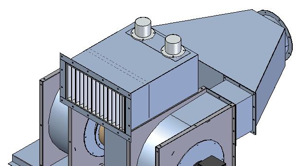
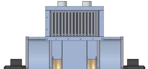

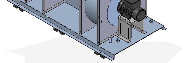
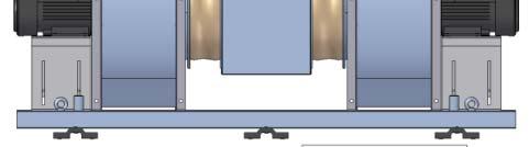
208 OFFSHORE PRODUCTS APPLICATIONS MSV 315 B1 FAN SKID C/W Air intake & filters for Ventilation of Drillers Cabin Drill Module
209 Example of Offshore Air Handling Units

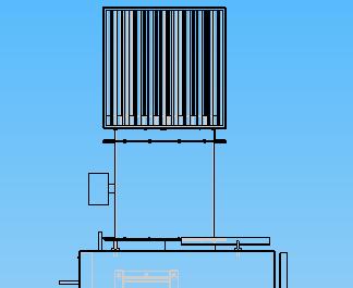
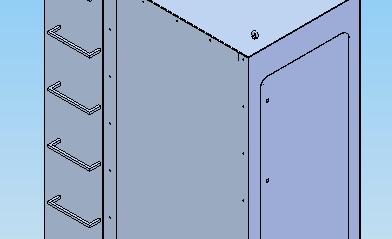
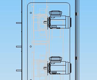
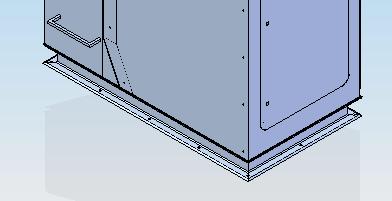
210 OFFSHORE PRODUCTS APPLICATIONS MSV 25 FAN CABINET C/W Air Intake for Ventilation of machine room Offshore cranes
211 Example of Offshore Air Handling Units
212 Reference project: Deepsea Rig Scope of Supply, Cooling Fans for Drawworks Deepsea Atlantic/Stavanger semi submersible drilling rig ultra deepwater and harsh environment Scope of Supply, Drillers Cabin Produkt Note before Orderline note DRS_G Pos.3: Droplet Seperator * Part of Air Intake/ Fan Skid 1 Produkt Note before Orderline note MSV7B1AF DRS_F 1 Pos.1: V1574/ AHD 5-46 Blower Skid f. Drawworks Motor Pos.2: Direct driven, medium pressure centrifugal fan, 22m3h Pos.3: Droplet Seperators Pos.4: Mounted on Fan outlet * Blower Skid in acc.to GA Drawing: * Blower Skid in acc.to Purch. Specs.: Each Blower Skid comprising the following: * 2off, Centrifugal fans, MSV 7 B1, listed below pos.2. * 2off, Inlet chambers, c/w droplet separators "DRS" and prefilterpad in 2/2. Chambers inside sound insulated. Access from top chambers. * 1off, Base frame, c/w cert. lifting lugs, Gunnebo and earthing Studs. * 2off, Backflow dampers, make BAAS, AISI 316. * 1off, Plenum chamber in AISI 316 execution. * Blower Skid to be packed in a disposable light tarpaulin * Insulating of fan housings with 5mm sound muffling plates * Drain Plug on fan housings, R 1/2" (Muff & Plug) * Motor : EExde - IIB/T4 - IP56 - Cenelec * Heater: 1x 23V/ 6Hz/ PTC Termistors incl. * Motor painted in acc. to ABB Offshore Paint System * Droplet Separator for Air Intake, Part of Inlet Chamber * 1pc. for each fan * Manufacturer: BAAS - Component AS * Main Dimensions: W5 x H7 x L3mm * Flange Details in acc. to Dwg.: * Dampers executed in AISI 316 * To be mounted in pairs opposite, airstream directed downwards(vertical) SKID1 SILENCER 1 Pos.5: Blower Skid F Ilt Pos.7: Sound Level Measurement * Internal Duct Size x Lenght: W1 x H125 x L13 * To be mounted bt d t l t /f i l t d ii tk h b Pos.1: Fan Skid Fan Inlet between adapterplate/ fan inlet and airintake chamber Drawing * Air Intake complete w/ Skid m/ 2x, dropletseparator "DRS and EU7 filter MSV 35 (CamGT). * Back-Flow Damper(BAAS), 2 Pos.6: Blower B1. SILENCER Skid Outlet pcs. For fan outlet * Flexibel collar, Ø 4, Execution monted on outlet of plenum chamber 2pcs. without / Supplyfans. resirc * Internal Duct Size x Lenght: W1 x H8 x L18 * To be mounted right after Blower Skid's Plenum Chamber * Silencers in acc. to Purch. Specs.: * Silencers, fixed mounted, in acc to GA Dwg * Silencers to be delivered as seperate items, but complete with neccesary accessories like bolts,washers & nuts. Each silencer to be clearly marked up where it belongs. * Compl. with Test Report for Levels for Acoustic Pressure/ Sound Levels. Report comprises 2pages. MSV35B1AF Pos.2: Supply Fans * External pressure drop for skid, max. 6Pa/Ps * Motor: EExde - IIB/T4 - IP56 - PTC Thermistorer * Motors c/w spaceheater 1x23V * Motors c/w offshore zink/ epoxy painting Documentation Pos.8: Final Documentation * Test & Inspection Reports in acc. to Natoil FAT Procedure * Sound Level Test Report, See Pos.7 above Quality by Experience - Efficiency by technology
213 Reference project: Deepsea Rig Deepsea RIG Nyborg AS has participated in delivering HVAC equipment to the following project, including Cooling fans for Drawworks and ventilation of drillers cabin, listed below also similar project of equal deliverance of different owners. Deepsea Atlantic and Deepsea Stavanger. The two units are scheduled for delivery from Daewoo Shipbuilding and Marine Engineering (DSME) in South Korea early 29 and 2 quarter 21 respectively. The first unit - Deepsea Atlantic has signed a long term contract with StatoilHydro in Norway. The second unit Deepsea Stavanger is currently being marketed World Wide. Green Rig Deepsea Atlantic / Stavanger is designed for environmental sensitive areas, and the utmost focus has been put on zero discharge, low emissions and electrical solutions to reduce onboard oil volumes and associated pollution risks. Separate drain systems are installed for the machinery area, drilling area and all outside clean deck areas. No drain water is discharged without passing a cleaning system which ensures acceptable oil content. Important installations and arrangements to obtain the green rig are: Enclosed derrick which prevents mud spill to sea. All drain lines routed to central cleaning unit by use of several tanks and pumps. Discharge from mud pits by pumping, no gravity discharge. Waste management system implemented Low emission of NOX, clean design engines. Closed loop BOP control system Electrical drawworks with power regeneration Similar References: Project to owners of: Mosvold Cosl Maersk Petrobras Gazflot Island Innovator Aker Oilfield Keppel Fels Stena Drillmax Transocean Quality by Experience - Efficiency by technology
214 Reference project: HVAC Mud module, for Maracc, Island Innovator Scope of Supply Produkt Note before Orderline note DRS_G Del av Pos.3, System S2 SKID1 Pos.1: System E11, 385m3h - 15Pa Ext. Fan Skid including Base frame - 2x. exhaust.fan, LSV 8 B1, data acc. pos x, Backflow damper on fan outlet, t BAAS. - 2x, Man Shut-Off Damper on Inlet, Ø 8, BAAS. - uninsulated plenumchamber - insulated single inlet chamber, 9. on fan inntake, opening 62 x 1mm - Compl. acc. to drw LSV8B1BG Pos.2: Extract Fans, System * Motors: EExe, II/T3, IP56, PTC Thermistors * Standstill heating, 1x23V E11 SKID1 Pos.3: System S2, 25m3/h - 6Pa Ext. Fan Skid including: * Compl. acc. to drw * base frame * uninsulated intakechamber * Intakelouver/ dropletseparator DRS 65x62 * EU7 filter CamGT, 1x, 1/1Bag * Supplyfans, 2x, acc. pos.4. * 2x, Backflowdamper on fanoutlet, t BAAS. * Plenumchamber * Magnehelic mounted td with tubing MSV35B1AF Pos.4: Supply Fans, System S2 * Motors: EExde, IIB/T4, IP56, PTC * Standstillheating, 1x23V MSV125B1BG Pos.5: Extract Fan, System E21 * Motor: EExde, IIB/T4, IP56. * Standstill heating, 1x23V * Drawing Quality by Experience - Efficiency by technology
215 Reference project: Island Innovator Nyborg AS has participated in delivering HVAC equipment to the following project, including two fan skid, Fan unit for Extr Shale Shaker Room, Mud tanks and Supply Fan unit for Mud Contr room, LER, Mud Lab. Listed below also similar project of equal deliverance of different owners. The intervention unit is the first of its kind, and is designed for North Sea operations. The GM4 is a fully equipped semi-submersible submersible unit based on proven design. Island Offshore is responsible for the marketing and management the vessel, as well as providing project management and supervision during construction. Island Offshore has an unrivalled track record, having performed numerous light well intervention operations for StatoilHydro, Chevron and Nexen. The GM4 is a state of the art top-side from National Oilwell Varco and Nymo. Similar References: Project to owners of: Awilco: WilPromotor WilPioneer WilInnovator Semi V Quality by Experience - Efficiency by technology

216 VENTILATION COWLS APPLICATIONS Heavy-duty cowls for marine applications, to be duct-top mounted. KH - R1O Ventilation cowl for protection against seawater spray and rain. Both for supply and exhaust of air. Cowl to be turned upwards for easy maintenance and inspection. Available for duct sizes from dia Ø25- Ø1. KH - R1F Fixed ventilation cowl. Available for duct sizes from dia Ø1- Ø14. KHE - R1F Jet cowl for upward discharge of exhaust air. Functional design protects against seawater spray and rain, with drainage. Available for duct sizes from dia Ø25- Ø1. KHS - R1OV Shutable ventilation cowl for protection of incoming seas and spray, and total weather tight design. Intended for mounting on low ventilation ducts. Dimensions are according classification societies for low ventilation ducts on main deck. Dimension G can be subtracted from the requirements of the heights of the ventilation ducts. The valve to be manually shut or opened, and can be locked either open or shut. The valve seals tightly against a ring of neoprene, by means of a spring load, also acting in open position. Cowl to be upturned for easy maintenance and inspection. Available for duct sizes from dia Ø25- Ø1. DESIGN Long experience has contributed to a simple and functional construction. Also tailor made solutions to meet customers specification, EXECUTION Normally manufactured in Grade A ship steel, hot dip galvanised. Other materials are sea water resistant aluminium or stainless steel. N-623 SYKKYLVEN, NORWAY TEL FAX
217 VENTILATION COWLS KH - R1O KHE - R1F KHS - R1OV N-623 SYKKYLVEN, NORWAY TEL FAX
218 NYBORG VENTILATION HOOD For Duct Top Installation All Hot-Dipped Galvanized KH - R1O T1 F T2 E A O D1 BCD=O C O B O D2 O D3 Z holes, Ø K Size A B C Ø D1 Ø D2 Ø D3 E F/ T1 T2 Z x K Weight x x x x x x x x x x x R.Berge 1/12-2 N-623 SYKKYLVEN, NORWAY TEL FAX KH - R1O
219 NYBORG VENTILATION HOOD For Duct-Top Installation All Hot-Dipped Galvanized KH - R1F T2 A O D1 T1 F E BCD =O C O B O D2 O D3 Z holes, Ø K Size A B C Ø D1 Ø D2 Ø D3 E F/ T1 T2 Z x K Weight xØ xØ xØ xØ R.Berge 13/12-2 N-623 SYKKYLVEN, NORWAY TEL FAX KH - R1F
220 t JET COWL KHE - R1F Wire Mesh O E O D+3 A + 1 A Draining Pipe Drain Gap O D Z holes, Ø K DC= O C O B Size A B C D E T Z x K x x x x x x x x x x x x x R.Berge 13/12-2 rev N-623 SYKKYLVEN, NORWAY TEL FAX KHE - R1F
221 SHUTABLE VENTILATION COWL KHS - R1OV T2 T2 O D2 A G Open Pos E O D3 Closed Pos T1 F O D1 BCD = O C O B Z holes, Ø K KHS A B C Ø D1 Ø D2 Ø D3 E F G T1 T2 Z x K Weight x x x x x x x x x x R.Berge 4/3-3 N-623 SYKKYLVEN, NORWAY TEL FAX KHS - R1OV
222 VENTILATION HOOD WITH WEATHER TIGHT CLOSING KHR 164 Lifting Lugs E D F A A T2 T1 Wire Guard Air Flow C.H. Open / Closed Indicator BCD = OC O B O A SECTION A-A A B C D E F C.H. T1 T ~ ,8 (1) ~ ~ ~ ~ ~ ~ ~ ~ ~ ~ Tegn.nr.: Dato: Tegn. av: SA.Drabløs N-623 SYKKYLVEN, NORWAY TEL FAX
223 Dim. ØD r t Md x k l Weight [kg] 5 6,3 8 6,3 M8x ,9 12 6,3 M8x5 78 2, , M8x ,7 19 8,8 M1x , ,3 24 8,8 M1x , ,1 3 8,8 M1x ,8 M1x ,9 45 8,8 M1x6 34 Remarks
224
225 DIMENSION DRAWING SWAN NECK TYPE C B Cotter Pin t1 t1 HDG r L L req. = 9 ( 76 ) Gasket t1 Deck O dim. Size (ND) ø dim t1 L r B 5 6,3 6,3 8 22,3 8 88,9 6, , , , ,7 8, , ,3 8, , ,1 8, , , ,9 8, , ,6 8, , F.Østro N-623 SYKKYLVEN, NORWAY TEL FAX SWAN NECK TYPE C
226 DIMENSION DRAWING SWAN NECK TYPE D OD L l 1 Md x k Dim. ØD r t Md x k l Weight [kg] L Remarks 51 6,3 8 6,3 M1 x ,9 12 6,3 M1 x , , M1 x ,7 19 8,8 M1 x , ,3 24 8,8 M12 x , ,1 3 8,8 M12 x ,8 M12 x ,9 45 8,8 M12 x ,6 53 8,8 M12 x ,4 61 8,8 M12 x Tegn.nr.: Dato: Tegn. av: SA.Drabløs N-623 SYKKYLVEN, NORWAY TEL FAX SWAN NECK TYPE D
227 N-623 SYKKYLVEN - NORWAY Tel: Fax office@nyborgfan.com - WEB:

228 DAMPERS APPLICATIONS Heavy-duty dampers are designed for marine applications. LSS R Butterfly valve with circular housing for air volume control or as a shut-off damper. Manually, electrically or pneumatically operated. Available for duct sizes from dia Ø2- Ø125. SSVent Rectangular Shut-Off Damper with Adapter-plate for circular application. Damper blades and shafts are executed in AISI 316L. Manually, electrically or pneumatically operated. Available for duct sizes from dia Ø71- Ø16. S.Vent R1OVL Butterfly Valve with Drain Gap for Overflow Water. Suitable for weather tight shut-off service of ventilating ducts on main deck. To be used where the heights of the ventilating top-ducts above deck are low. Mainly fitted with manual actuators as hand-wheels or levers. For remote control the valves can be supplied with electric, pneumatic or hydraulic actuators. Available for duct sizes from dia Ø15- Ø125. DESIGN Long experience has contributed to a simple and functional construction. Also tailor made solutions to meet customer s specification. EXECUTION Normally manufactured in Grade A ship steel, hot dip galvanized. Other materials are sea water resistant aluminium or stainless steel. N-623 SYKKYLVEN, NORWAY TEL FAX
229 DAMPERS LSS - R SSVENT S.VENT - R1OVL N-623 SYKKYLVEN, NORWAY TEL FAX
230 NYBORG CIRCULAR SHUT-OFF DAMPER LSS - R DC= O C OPEN POS O D O B 4 CLOSED POS T E Z holes, Ø H A F 1 DAMPER HOUSING, Matl. : St.37, Hot Dipped Galvanized 2 DAMPER PLATE, Matl.: AISI 316L 3 OPERATING FIELD, c/w open/closed Indicator 4 OPERATING HANDLE, c/w Clamping Screw and Wing Nut 5 DAMPER SHAFT, Matl. : AISI 316L To be equipped with actuator (pneumatical or electrical) up to size Ø 63 DIA A B C Ø D E F T Z ØH /11-2 R.Berge N-623 SYKKYLVEN, NORWAY TEL FAX LSS - R
231 NYBORG RECTANGULAR SHUT-OFF DAMPER SSVent O max.3 = = = = = 15 = = 15 = = max. 3 a H + 12 O DIA 8 H x B B NYBORG RECTANGULAR SHUT-OFF DAMPER, DESIGNED FOR CIRCULAR APPLICATION, SSVent BxH, made of hot dipped galv. Steel. Damper blades and shafts in AISI 316L. Adapterplate is made of hot dipped galv. steel. Equipped with electrical or pneumatical actuators. DIA B H Actuator a N 1 B 8 E 2 19/11-2 R.Berge N-623 SYKKYLVEN, NORWAY TEL FAX SSVent
232 BCD=O C BUTTERFLY VALVE WITH DRAIN GAP FOR OVERFLOW WATER S.Ventil R1(2)OVL O B DC=O C F2 T2 V U S F1 T1 O D W Y R P Z holes, O K O Size ØB ØC ØD O P R Y S U V W F1 F2 T1 T2 Z K /3-3 R.Berge N-623 SYKKYLVEN, NORWAY TEL FAX S-Ventil R1(2)OVL
233 BUTTERFLY VALVE weather and water tight B-Vent G D E A BCD = B Z holes x K C H F SSL A B C D E F G H Z x K Weight x M x M x M x M x M x M x M x M SA. Drabløs N-623 SYKKYLVEN, NORWAY TEL FAX B-Vent
234 CONECTING PIECE WITH OR WITHOUT FLANGE B-Vent For connection to B-Vent 1 B Nyborg standard for connection to fan Z x OK BCD=C D A A B C D Z x K x x x x x x x x 26 Tegn.nr.: Dato: Tegn. av: SA.Drabløs N-623 SYKKYLVEN, NORWAY TEL FAX B-Vent 15-5
235 REGULATING APPARATUS A-4, A-5, A-56 and A-63 TYPE ADJUSTED BY SERVOMOTOR N-623 SYKKYLVEN, NORWAY TEL FAX
236 REGULATING APPARATUS A-8 and A-1 TYPE N-623 SYKKYLVEN, NORWAY TEL FAX
237 REGULATING APPARATUS A-8 and A-1 TYPE N-623 SYKKYLVEN, NORWAY TEL FAX

238 REGULATING APPARATUS A-4, A-5, A-56 and A-63 TYPE MANUALLY CONTROLLED N-623 SYKKYLVEN, NORWAY TEL FAX
239 WEATHER LOUVRES SR - F SRL - F SSVENT SSVENT - FS N-623 SYKKYLVEN, NORWAY TEL FAX

240 WEATHER LOUVER with closing damper SSVent-FS (BxH) General: The SSVent-FS is a combined rectangular single stage weather louver with an integrated closing damper. The louver is made / delivered in customer specified sizes, but it is recommended to use standard heights for best performance. Applications: For ship and offshore/rig applications. The SSVent-FS is used where weather tight closing is not needed, primarily for exhaust, but also for supply if some ingress of rain is acceptable.. The damper is mainly used as shut off damper, but can also be used as a regulating damper for air volume control. Design The damper is operated by lever / regulating arm from the outside, and the leaver is on right side (seen from outside) as standard. The louver is intended for flange mounting to bulkhead and is penetrating the bulkhead. Execution: The frame and weather louver is as standard in mild steel, hot dip galvanized. All movable parts like damper blades, bolts, shafts, hinges, regulating arm are in stainless steel execution. Cut out W cut out = W louver +5, H cut out = H louver +2 to +5. Radius on cut out max : 5mm for (2+5 cut out), max7mm for 5x5mm cut out. Actuator As standard manual regulating from outside, but when access from outside is difficult the louver can be delivered with a electric or pneumatic actuator. See section for dampers for more info on actuators. Optional material execution. Frame and louver in sea water resistant aluminium (damper blades and movable parts in stainless steel). Complete louver in stainless steel (aisi 34) or aisi 316 execution. N-623 SYKKYLVEN, NORWAY TEL FAX
241 WEATHER LOUVER with closing damper SSVent-FS (BxH) Options With wire mesh (12x12x1 aisi316) in front or back side of louver. With sand filter in front With filter Painted (after galvanization). Electric or pneumatic closing damper. With regulating arm from operated from inside, or extended arm for outside. Performance Supply: max recommended facevelocity 5,5 m/s Exhaust: max recommended face velocity 6-6,5m/s Calculation of face velocity: Face velocity [m/s] = air flow [m 3 /s] / WxH [m 2 ] Special designs: With flange on specified placement of frame (louver partly penetrating bulkhead) With complete louver on outside of bulkhead. Dimensions 15 max. 3 = = = = 15 O 14 B-12 H max.3 = = = = 15 B + 12 Cutout Bulkhead : H+5 x B+5 H x B 6 Bulkhead 25 N-623 SYKKYLVEN, NORWAY TEL FAX
242 NYBORG SHUTABLE BLADE DAMPER SSVent B x H FS H max. 3 = = = = 15 O 14 B-12 H max.3 = = = = 15 B + 12 Cutout Bulkhead : B+5 x H+5 B x H 6 Bulkhead 25 B H B H NYBORG BLADE DAMPER SSVent B x H FS, made of hot dipped galv. St.37. Damper blades and shafts in AISI 316L. 29/8- R.Berge N-623 SYKKYLVEN, NORWAY TEL FAX SSVent B x H FS
243 WEATHER LOUVER SR-F & SR-G (BxH) General The SR-F is a rectangular single stage weather louver which is produced in customer specified sizes. The function is to protect the ventilation duct from rain and light sea spray Applications The louver is primarily used as exhaust louver where weather tight closing is not needed, but it can also be used for supply where some ingress of water is acceptable. Optional execution. Sea water resistant aluminium Stainless steel (aisi 34) or aisi316, Options With wire mesh (12x12x1 aisi316) in front or back (inside) of louver. With sand filter in front With filter Painted (after galvanization). Models: SR-F with flange for bolting to bulkhead SR-G without flange for welding to bulkhead Performance: Recommended max air speed for supply: 5,5 m/s Recommended max air speed for exhaust 6-6,5m/s Design: For the SRL-F the louver can be both penetrating bulkhead or be mounted entirely on the outside. For best performance as exhaust louver the latter is recommended. Calculation of face velocity: Face velocity [m/s] = air flow [m 3 /s] / WxH [m 2 ] Execution: The frame and blades are made in mild steel, hot dip galvanized. Cut out W cut out = W louver +2, H cut out = H louver +2. If the louver is mounted on outside of the bulkhead no radius on cut out will conflict with louver. If the louver is penetrating bulkhead radius on cut out should be max 35mm. N-623 SYKKYLVEN, NORWAY TEL FAX
244 N-623 SYKKYLVEN - NORWAY Tel: Fax office@nyborgfan.com - WEB:
245 N-623 SYKKYLVEN - NORWAY Tel: Fax office@nyborgfan.com - WEB:

246 WEATHER LOUVER with weather tight closing SRL-F & SRL-G BxH General: The SRL-F is a rectangular, single stage weather louver with a weather tight hatch. The louver is made in customer specified sizes. The louver is to prevent ingress of rain into the ventilation system. Applications The louver is designed for use for marine vessels, or for rig applications. The SRL is used primarily for exhaust, but can be used for supply where some ingress of water is acceptable. Models: SRL-F: With flange for bolting to bulkhead. SRL-G: Without flange for welding to bulkhead. Design The louver is available in all sizes.(tailor made) and is delivered either top-, bottom- or side (left- or right hinged.) The hinges are equipped with greasing nipples for lubrication The Max recommended size of the louver is approx 3-3,5 m2, For bigger louvers the hatch should be divided in two pieces. Execution The frame, profiles and hatch are executed in mild steel, hot dip galvanized. All bolts and nuts are in stainless steel execution. The louver achieves a weather tight closing by a neoprene gasket. Cut out: W cut out = W louver, H cut out = H louver. As the louver is mounted on outside of bulkhead no radius on cut out will conflict with the louver. Optional execution. Sea water resistant aluminium Frame and hatch in stainless steel (aisi 34) or aisi316, Frame and profiles in steel, hot dip galvanized, hatch in aluminium Options With wire mesh (12x12x1 aisi316) in front or back (inside) of louver. With sand filter in front With filter With locking arm for keeping louver in open position at specified angle (e.g. 3deg) With locking bolt for locking hatch to bulkhead (must be welding to bulkhead) (for 9 or 18 deg opening) Painted (after galvanization). Special designs: Folded hatch (e.g. where space for hatch is limited(f.eks. pga gangveier) Divided hatch (e.g. one louver with one bottom- and one top hinged hatch). Louver with hatch for 27 deg opening. Without lamellas/profiles (only frame and hatch). N-623 SYKKYLVEN, NORWAY TEL FAX
247 WEATHER LOUVER with closing damper SSVent-FS Performance: Recommended max air speed for supply: 5,5 m/s Recommended max air speed for exhaust 6-6,5m/s Dimensions SRL-F B max. 25 max x6x6 H + 11 max max B + 43 H + 43 H x B 8 ca. 17 N-623 SYKKYLVEN, NORWAY TEL FAX
248 N-623 SYKKYLVEN - NORWAY Tel: Fax office@nyborgfan.com - WEB:
249 N-623 SYKKYLVEN - NORWAY Tel: Fax office@nyborgfan.com - WEB:


250 MIST ELIMINATOR LOUVERS Overview Mist eliminator louvers are used for air intakes for separation of water droplets, moisture and some salt spray from the air stream. This reduces corrosion, mold and other moisture related problems, and usually mean reduced maintenance and significant savings for the owner. Models: DRS-F and DRS-G DRSL-F and DRSL-G SSvent-FS/DRS-G DRS-FiMO-F and DRS-FiMi-F DRS-FiZO-F and DRS-FiZi-F standard mist eliminator mist eliminator with weather tight hatch mist eliminator with integrated shut off damper. mist eliminator with filter prefabricated modules Mist eliminator with filter filter from roll, tailor made sizes N-623 SYKKYLVEN, NORWAY TEL FAX
251 MIST ELIMINATOR LOUVERS DRS - F DRSL - F N-623 SYKKYLVEN, NORWAY TEL FAX
252 MIST ELIMINATOR LOUVERS PERFORMANCE DATA Performance: Recommended face (gross) air velocity is 4,5-5 m/s. For louvers with e.g. area <,3m2 it is recommended to reduce this velocity by 5-1% due to smaller net area. Calculation of face velocity Face velocity [m/s] = air flow [m 3 /s] / BxH [m 2 ] (face velocity = air flow / louver gross area) Pressure drop, Ps [Pa] Pressure drop, material: aluminium (standard) SSVent-FS/DRS-G DRS, DRSL Pressure drop, Ps [Pa] Pressure drop, material: stainless steel Aisi34/316 (optional) SSVent-FS/DRS-G DRS, DRSL face velocity, v [m/s] face velocity, v [m/s] 1 Water separation Efficiency [%] face velocity, v [m/s] N Y B O R G A S N-623 Sykkylven, Norway TEL FAX

 at the bottom of the louver.")
253 MIST ELIMINATOR LOUVER w closing damper SSVent-FS/DRS-G BxH General: The SSVent-FS is a single stage mist eliminator louver with a integrated closing damper. The louver is made in customer specified sizes. Applications: The SSVent-FS/DRS-G is used as an air intake where weather tight closing is not demanded. The damper is primarily intended as a shut off damper, but can also be used as an air volume control / regulating damper. Design and drain The louver has vertical profiles with grooves/water traps where the water is led down and drained out to the front (outside) at the bottom of the louver. The damper is operated by lever / regulating arm from the outside. The louver is intended for flange mounting to bulkhead and is penetrating the bulkhead. Execution The frame is as standard in mild steel, hot dip galvanized, the mist eliminator is made in sea water resistant alum. All movable parts like damper blades, bolts, shafts, hinges and regulating arm are in stainless steel execution. Optional material execution Frame and mist eliminator louver in sea water resistant aluminium (damper blades in stainless steel). Frame and damper blades in stainless steel and mist eliminator louver in alum. Complete louver in stainless steel (aisi 34) or aisi 316 execution. Cut out W cut out = W louver +5mm, H cut out = H louver + 5mm. Radius on cut out: max 5mm. Actuator As standard manual closing from outside (actuator as standard on the right side). Where access to actuator from outside is difficult an electric or pneumatic fail safe actuator can be used. (See chapter for dampers for more info). Options With wire mesh (12x12x1 aisi316) in front or back side of louver. With sand filter in front With filter Painted (after galvanization). Electric or pneumatic actuator for damper. With regulating arm on left side. With regulating arm from operated from inside. Special designs: With flange on specified placement of louver (louver partly penetrating bulkhead) Complete louver designed for mounting on outside of bulkhead Without flange for welding to bulkhead N-623 SYKKYLVEN, NORWAY TEL FAX
254 NYBORG SHUTABLE BLADE DAMPER WITH INTEGRATED WEATHER LOUVRE SSVent B x H FS / DRS B x H G H max.3 = = = = 15 O 14 B - 12 H max = = 15 Cutout Bulkhead : H + 5 x B + 5 H x B 6 Bulkhead 275 max. 3 B + 12 B x H max. 48 H H NYBORG BLADE DAMPER SSVent B x H FS, made of hot dipped galv.st.37. Damper blades and shafts in AISI 316L. NYBORG WEATHER LOUVRE DRS B x H G, made of high tensile alum. alloy,salt resistant. 26/3-1 R.Berge N-623 SYKKYLVEN, NORWAY TEL FAX SSVent B x H FS / DRS B x H G

 at the bottom of the louver.")
255 MIST ELIMINATOR LOUVER DRS-F & DRS-G BxH General The DRS-F is a rectangular single stage mist eliminator louver for separation of water droplets and moisture from the air stream. Delivered in customer specified sizes. Applications The louver is primarily used as intake louver. Typical examples are engine room intakes, intake for accommodation, cargo hold etc. Models: DRS-F with flange for mounting onto bulkhead DRS-G without flange for insertion into steel duct, frame or similar. Design and drain The louver has vertical profiles with water traps where the water is led down and drained out to the front (outside) at the bottom of the louver. As standard the mist eliminator louver is penetrating into the bulkhead. Execution: The complete louver is made of sea water resistant alum. Optional material execution: Entire louver in stainless steel, aisi 34 or aisi 316L Cut out: W cut out = W louver +2, H cut out = H louver +2. Max radius on the cut out is 35mm. For a bigger radius the louver must be made with wider flanges.. Options: With wire mesh behind (or in front of) the louver (12x12x1 stainless steel) With sand filter in front for easy removal / cleaning (filter class G2 or G3) With filter behind louver (for dust/soot) (G3 or G4) With drain pipe either with drain to front or to inside. Panted Special designs: With access door (e.g. 8x8mm) Hinged execution (entire louver) for access For mounting entirely on the outside of bulkhead. One or more sides of louver inclined (e.g. triangular shape). N-623 SYKKYLVEN, NORWAY TEL FAX
256 NYBORG HIGH EFFICIENCY DROPLETS SEPARATOR DRS B x H F min 2 B max 25 = = = = 15 O 14 8 B x H min 2 max 25 H + 84 = = 15 5 max. 3 NYBORG HIGH EFFICIENCY DROPLET SEPARATOR DRS B x H F, made of high tensile alum.alloy, salt resistant. Bulkhead Cutout : H + 2 x B /8-4 R.Berge N-623 SYKKYLVEN, NORWAY TEL FAX DRS B x H F
257 NYBORG HIGH EFFICIENCY DROPLETS SEPARATOR DRS B x H G B H 8 B x H 125 max. 3 NYBORG HIGH EFFICIENCY DROPLET SEPARATOR DRS B x H G, made of high tensile alum. alloy, salt resistant. 29/8- R.Berge N-623 SYKKYLVEN, NORWAY TEL FAX DRS B x H G

 Design and drain The mist eliminator part of the louver has vertical profiles with water traps.")
258 MIST ELIMINATOR LOUVER with weather tight closing DRSL-F & DRSL-G BxH General: The DRSL is a single stage mist eliminator for separation of water droplets and moisture with a weather tight hatch. The louver is made in customer specified sizes. Applications: The louver is primarily used as air intake / supply louver where you have demand for weather tight closing. It can also be used as an alternative to a shut off damper. Typical applications are intake for accommodation, technical rooms, etc. Models DRSL-F: with flange for bolting to bulkhead DRSL-G: without flange for welding to bulkhead (e.g. for curved bulkhead) Design and drain The mist eliminator part of the louver has vertical profiles with water traps. The water is led down and drained out to the front (outside) at the bottom of the louver. The hatch can be top-, bottom-, left- or right hinged The hinges are equipped with grease nipples for lubrication. Optional Execution. All louver in sea water resistant aluminium Frame and hatch in stainless steel (aisi 34 or 316), mist eliminator louver in sea water resistant alum. All louver in stainless steel (frame, hatch and mist eliminator). Cut out W cut out = W louver, H cut out = H louver. Radius on cut out: For standard design the louver will not conflict with cut out. If the louver is special designed to penetrate the bulkhead Rmax is 2mm. Options Wire mesh (12x12x1 aisi316) behind (or in front) of louver. With sand filter in front of louver With filter behind louver With locking arm for keeping louver in open position at specified angle (e.g. 3deg) for top hinged louvers With locking bolt for locking hatch to bulkhead (must be welded to bulkhead) (for side- or bottom hinged louver). With drainpipe either to outside or to inside. Painted (after galvanization). Execution The frame and hatch are executed in mild steel, hot dip galvanized. The mist eliminator part is executed in sea water resistant alum. Locking bolts, toggles and nuts are in aisi 316 Special designs: Folded hatch (e.g. where space for hatch is limited). Divided hatch (e.g. one louver with one bottom- and one top hinged hatch). Louver with hatch for 27 deg opening. With short frame (louver is partly penetrating the bulkhead). N-623 SYKKYLVEN, NORWAY TEL FAX
259
260 MIST ELIMINATOR LOUVER with filter (prefabricated modules) DRS-FiMO-F & DRS-FiMi-F BxH General The DRS-F w filter is a two stage intake louver with a mist eliminator louver in front followed by a filter as the 2 nd stage. The filter section is made up by prefabricated modules in standard sizes. The filter prevents soot, dust, sand, insects or salt etc from being sucked into the ventilation system and the rooms to be ventilated. Applications: Used for air intake where removal of soot, sand, dust, moisture, insects etc from the air stream is desired. Typically used for engine room intake, accommodation, but can also be used as pre-filter, e.g. for turbo intake. Models DRS-FiMO-F with hinged louver for access to filter from front (outside). DRS-FiMi-F with access to filter from inside (back side of louver). Design and drain The louver has vertical profiles with grooves/water traps where the water is led down and drained out to the front (outside) at the bottom of the louver. The louver is only made in certain step sizes due to using prefabricated standard filter modules. Standard filters from most filter manufacturers can be used. For the DRSFaF-F, there is one detachable bar, giving an opening of min 56x9 (WxH) if access to inside is needed. Execution: the louver and the filter frame are made in sea water resistant aluminium. The frames for the prefabricated filter usually are made of plastic. Special execution: Louver and filter frame in stainless steel. Mist eliminator louver in alum and frame in stainless steel. Cut out: W cut out = W louver +2, H cut out = H louver +2. Max radius on the cut out is 35mm. For a bigger radius the cut out can be increased to +4mm. Special design. Louver and filter section for mounting completely on outside on bulkhead (e.g. if limited space behind louver/filter). With access to filter from the side (through inspection hatch). Filter/Performance Filter can be delivered in EU 3, 4, 5, 6 and 7 class. The prefabricated modules gives a high effective filter area, superior filtration, lower pressure drop and long time between filter change compared to plan filters (Filter) Maintenance When filter has reached recommended pressure drop it should be cleaned or changed. Time between change of filter will depend of environment for ship operation. A quick locking system makes filter changes quick and simple. Options: Louver equipped with pressure meter for indication of time for filter change. Drainpipe, either to outside or inside. wire guard for louver on inside (or outside), 12x12x1 stainless steel. Pre-filter (EU2) in front of louver to prolong lifetime for the (more expensive) main filters. N-623 SYKKYLVEN, NORWAY TEL FAX
261 MIST ELIMINATOR LOUVERS with filter (prefabricated modules) DRS FiMO-F & DRS FiM -F BxH Filters Filter characteristics Initial pressure drop [Pa] Rec. final press. drop Average arresistance Dust holding cap Filter suitable for Depth of filter [mm] Nominal face velocity [m/s] Max rec. face velocity [m/s] Table filter characteristics Filter class G3 (EU3) G4 (EU4) F5 (EU5) F6 (EU6) F7 (EU7) ,92,95 4kg/m2 3kg/m2 3kg/m2 6kg/m2/@8Pa 5kg/m2/@8Pa course dust, also soot, some also finer soot, also salt, also moisture insects, sand moisture some moisture moisture, (14) 292 (14) 3 2,75 2,5 3,1 3,1 3,5 3,5 3, Dimensions: Only stepwise sizes available. Face area indicated in table. B \ H ,2,39,58,78,97 62,19,39,58,77,96 1,15 1,34 1,53 1,72 1,91 93,58 1,15 1,72 2,29 2, ,39,77 1,15 1,53 1,91 2,29 2,67 3,5 3,43 3, ,96 1,91 2,86 3,81 4,76 185,58 1,15 1,72 2,29 2,86 3,42 3,99 4,56 5,14 5, ,34 2,67 4 5,33 6, ,78 1,54 2,3 3,6 3,83 4,58 5,34 6,1 6,87 7, ,73 3,44 5,16 6,87 39,97 1,91 2,87 3,81 4,76 5,7 6,65 7,63 Table 14.2: face area as function of louver dimensions. = not applicable Pressure drop, Ps [Pa] Filter (EU5) filter (EU7) Filter (EU6) louver Filter (EU4) Calculation of air flow through louver Air flow [m 3 /s] = face velocity [m/s] * face area [m 2 ] Pressure drop Total pressure drop = pressure drop louver + pressure drop filter Face velocity, v [m/s] nybmw 9-15 N Y B O R G A S N-623 Sykkylven, Norway TEL FAX
262 MIST ELIMINATOR LOUVER with FILTER, Prefabricated filter modules Hinged for access from front DRS-FiMO-F B x H max 3 A = = = = = = = 15 O 14 D 131 Bulk head = = = H + 1 = H H-48 = = Air Flow B = B A B + 1 B 6 SECTION A-A Drain to outside Compact or bagfilter Mist eliminator louver (alum.) Dimensions, WxH [mm], and face area [m2] B - 48 SECTION B-B Hinged doors W \ H ,2,39,58,78,97 62,19,39,58,77,96 1,15 1,34 1,53 1,72 1,91 93,58 1,15 1,72 2,29 2, ,39,77 1,15 1,53 1,91 2,29 2,67 3,5 3,43 3, ,96 1,91 2,86 3,81 4,76 185,58 1,15 1,72 2,29 2,86 3,42 3,99 4,56 5,14 5, ,34 2,67 4 5,33 6, ,78 1,54 2,3 3,6 3,83 4,58 5,34 6,1 6,87 7, ,73 3,44 5,16 6,87 39,97 1,91 2,87 3,81 4,76 5,7 6,65 7, D Filter box Cutout: B louver + 2mm H louver + 2mm Rmax 35mm One door B < 14 Two doors B > 14 Calculation of air flow through louver Air flow [m3/s] = face velocity [m/s] * face area [m2] Tegn.nr.: Dato: Tegn. av: SA.Drabløs N-623 SYKKYLVEN, NORWAY TEL FAX DRS-FiMO-F B x H
263 MIST ELIMINATOR LOUVER with FILTER, Prefabricated filter modules For access to filters from inside DRS-FiMi-F B x H 15 A max 3 max 3 15 = = = = = = = = = 15 D Bulk head Air Flow B B 6 = = = = = H = = = 15 H + 1 = A B + 1 B SECTION A-A Compact or bagfilter ~ D Filter box Cutout: B louver + 2mm H louver + 2mm Rmax 35mm SECTION B-B Dimensions, WxH [mm], and face area [m2] W \ H ,2,39,58,78,97 62,19,39,58,77,96 1,15 1,34 1,53 1,72 1,91 93,58 1,15 1,72 2,29 2, ,39,77 1,15 1,53 1,91 2,29 2,67 3,5 3,43 3, ,96 1,91 2,86 3,81 4,76 185,58 1,15 1,72 2,29 2,86 3,42 3,99 4,56 5,14 5, ,34 2,67 4 5,33 6, ,78 1,54 2,3 3,6 3,83 4,58 5,34 6,1 6,87 7, ,73 3,44 5,16 6,87 39,97 1,91 2,87 3,81 4,76 5,7 6,65 7,63 Calculation of air flow through louver Air flow [m3/s] = face velocity [m/s] * face area [m2] Tegn.nr.: Dato: Tegn. av: SA.Drabløs N-623 SYKKYLVEN, NORWAY TEL FAX DRS-FiMi-F B x H
264 MIST ELIMINATOR LOUVER with filter (in tailor made sizes) DRS-FiZO-F & DRS-FiZi-F BxH General The DRS-FiZO and FiZi are two stage mist eliminator louvers with the filter behind as the 2 nd stage. The filter is cloth from roll that is fastened to a frame. The louver can be made in tailor made sizes, but has standard heights in steps of 6mm. Applications: Used for air intake where removal of soot, sand, dust, moisture, insects etc from the air stream is desired. Typically used for engine room intake, accommodation, but can also be used as pre-filter, e.g. for turbo intake. Models DRS-FiZO-F with hinged louver for access to filter from outside (front). DRS-FiZi-F with access to filter from inside (back side of louver). Design and drain The louver has vertical profiles, and the separated water droplets are led down and drained to the front (outside) Execution: the louver is made in sea water resistant aluminium, while the frame for the filter is as standard stainless steel, aisi 34. Cut out: W cut out = W louver +4, H cut out = H louver +4. Max radius on the cut out is 6mm. For a bigger radius the louver must be made with wider flanges. Special design. Louver and filter section for mounting completely on outside on bulkhead (e.g. if limited space behind louver/filter). With access to filter from the side (through inspection hatch). Filter/Performance Filter can be delivered in EU 3, 4 or 5 class. The filter cloth is synthetic filter and is vashable. (Filter) Maintenance When filter has reached recommended pressure drop it should be cleaned or changed. Time between change of filter will depend of environment. A quick locking system makes filter changes quick and simple. Options: Louver equipped with pressure meter for indication of time for filter change. Drainpipe, either to outside or inside. wire guard for louver on inside (or outside), 12x12x1 stainless steel. Special execution: Louver and filter frame in stainless steel. Mist eliminator louver in alum and frame in stainless steel. N-623 SYKKYLVEN, NORWAY TEL FAX
265 MIST ELIMINATOR LOUVERS with filter (from roll) in customer specified sizes DRS FiZO F & DRS FiZi F BxH Filters Filter characteristics Initial pressure drop [Pa] Rec. final press. drop [Pa] Average arresistance [%] Filter class G3 (EU3) G4 (EU4) Filter suitable for course dust, also soot, some insects, sand moisture Depth of filter [mm] Nominal face velocity [m/s] Max rec. face velocity [m/s] Table filter characteristics ,75 4,5 Pressure drop with depth of filter = 25mm (D=25). Pressure drop, Ps [Pa] Filter (EU4) Filter (EU3) louver Calculation of air flow through louver Air flow [m 3 /s] = face velocity [m/s] * face area [m 2 ] Pressure drop Total pressure drop = pressure drop louver + pressure drop filter Face velocity, v [m/s] Pressure drop is based on standard depth of filterbox of 23 24mm. A shorter filter box will give a higher pressure drop. nybmw 9-17 N Y B O R G A S N-623 Sykkylven, Norway TEL FAX DRSFiF F & DRSFiB F BxH
266 MIST ELIMINATOR LOUVER With FILTER, customer made sizes Hinged for access from front DRS-FiZO-F B x H Bulk Head = = A = = = = = 15 O 14 D = = = 15 = H + 1 = = = = Air Flow 8 H - 48 Filter box (alum.) A B + 1 B B - 48 Filter Filter frame (AISI 34) 6 SECTION A-A Drain to outside (front) Cut out in bulk head B louver + 4mm H louver + 4mm Rmax 65mm Tegn.nr.: Dato: Tegn. av: SA.Drabløs Mist Eliminator (alum.) Standard heights in steps of 6mm H [mm] Dimensions: B min 2mm H min 28mm D (Depth) 18 standard. Min 13mm N-623 SYKKYLVEN, NORWAY TEL FAX Hinged Doors One Door B < 14 Two Doors B > 14 DRS-FiZO-F B x H
267 MIST ELIMINATOR LOUVER With FILTER, customer made sizes Access from inside (back side) DRS-FiZi-F B x H A 15 = = = = = = = = (std) Bulk Head Air Flow = = = H + 1 = = = = 15 = Service Area Filter box (alum.) A B + 1 Filter Optional Flange Placement SECTION A-A Filter frame (AISI 34) Drain to outside (front) Tegn.nr.: Dato: Tegn. av: SA.Drabløs Mist Eliminator (alum.) Standard heights in steps of 6mm H [mm] Minimum dimensions: B min 2mm H min 28mm N-623 SYKKYLVEN, NORWAY TEL FAX Cut out in bulk head B louver + 4mm H louver + 4mm Rmax 65mm DRS-FiZi-F B x H
. Circular High Efficiency Silencer with Core, for flange connection. Where extra damping is necessary. Available in sizes from dia Ø63 - Ø16.")
268 SILENCERS APPLICATIONS Heavy-duty Silencers for marine applications. LD LDC Circular High Efficiency Silencer for flange connection. Available in sizes from dia Ø315 - Ø16. Length 1D or 2D (Length = 1 x diameter). Circular High Efficiency Silencer with Core, for flange connection. Where extra damping is necessary. Available in sizes from dia Ø63 - Ø16. Length 1D or 2D (Length = 1 x diameter). To be mounted directly to axial fans or in-duct. DESIGN Also tailor made solutions to meet customer s specification. EXECUTION The Silencer is normally manufactured in Grade A ship steel, hot dip galvanized. 1 mm insulation material, type Rockwool, with perforated stainless steel plate, AISI 316L inside. N-623 SYKKYLVEN, NORWAY TEL FAX
269 SILENCERS LD LDC (with core) N-623 SYKKYLVEN, NORWAY TEL FAX
270 SOUND ATTENUATOR LD & LDC A LDC T2 A O D O B T1 DC=O C Z holes, K threads DETAIL A LD A=1D A=2D B C D T1 T2 Z x K xM xM xM xM xM xM xM xM xM xM xM xM xM xM16 LD R.Berge 24/2-3 N-623 SYKKYLVEN, NORWAY TEL FAX LD & LDC
271 TECHNICAL DATA The pressure for LD (without core) equals the pressure drop for ductwork with equal length. The pressure drop for LDC (with core) se below Air flow vs Pressure drop, Model LDC 1D 2 Pa size Air flow vs Pressure drop, Model LDC 2D size Pa 1 1 Differential Pressure - Kg/cm2 5 Differential Pressure - Kg/cm2 5 1,1 1 1,5 5 5 m 3 /s Sound attenuation For LDC the attenuation will depend on the blade angle of the axial fan. For LD the blade angle is ignorable. Silencers in duct Static attenuation Size Model Attenuation db k 2k 4k 8k LD 1D LD 2D LDC 1D LDC 2D LD 1D LD 2D LDC 1D LDC 2D LD 1D LD 2D LDC 1D LDC 2D LD 1D LD 2D LDC 1D LDC 2D LD 1D LD 2D LDC 1D LDC 2D LD 1D LD 2D LDC 1D LDC 2D LD 1D LD 2D LDC 1D LDC 2D LD 1D LD 2D LDC 1D LDC 2D ,1 1 1,5 5 5 m 3 /s Silencer mounted directly on axialfan in duct Dynamical attenuation Blade angle small refers to 2-25, medium to 3-35 and big to 4-45 Blade Attenuation db Size Model angle k 2k 4k 8k LD 1D All Small LDC 1D LD 2D Medium Big Small Medium Big Small LDC 2D Medium Big LD 1D All Small LDC 1D Medium Big Small LD 2D Medium Big Small LDC 2D Medium Big LD 1D All Small LDC 1D Medium Big Small LD 2D Medium Star Small LDC 2D Medium Big LD 1D All Small LDC 1D Medium Big Small LD 2D Medium Big Small LDC 2D Medium Big N-623 SYKKYLVEN - NORWAY Tlf: Fax
272 SS Vent 26 O 16 Silencer NOVIBRA DAMPERS Fan DC= O 169 O OFF Ø Dato Konstr./Tegnet Godkjent Målestokk F. Østro Gen. Arr. Drawing Henvisning: E.Nyborg Beregning: 1:2 NYBORG AS Erstatning for: N-623 SYKKYLVEN Erstattet av: MPV 16 D1K / Silencer / SS Vent
273 1 pcs Novibra Vibr. dampers mounted between 2 pcs contra-flanges. 1 pcs M12 bolts to be threaded to vibr. dampers. Sound atten. to be mounted to deck penetration by M16 bolts, Threaded Flange Brackets, Pl.12 Angle Bar 15x75, Welded to Deck- Housing M16 threads A O 112 A 28 3 Shut Off Damper 125x125 Split Out type Axial Fan Ø 112 Collar with flexible Connection and Novibra Dampers Not in Our Scope of supply! Deck Penetration, Ø 112 Sound Attenuator, Ø DC= O 12 2 pcs. M16 on Sound Att O 112 B Detail of Novibra Type C75/36 36 O 75 M12x12 DETAIL B 2 pcs. Ø 19 in lower Deck-Flange 1 pcs. Ø 16 in Upper Deck-Flange WW Lines Ro/Ro Carrier MKII M/V Tampa Fan. No.: 36, 1,2,3,4,5,6,7,8,9,1,11,12,13,14,15,16,17,2 Dato Konstr./Tegnet Godkjent Målestokk 28/5-2 R.Berge E.Nyborg 1:2 NYBORG AS N-623 SYKKYLVEN Erstatning for: Erstattet av: SECTION A-A Gen. Arr. Drawing MPV 112 A/D1M/SSVent / LD Henvisning: Beregning: As Built 14/11-2 R.B.
274 RESILIENT MOUNTINGS PRINCIPLE SKETCH MPV A1K N-623 SYKKYLVEN - NORWAY Tel: Fax office@nyborgfan.com - WEB: MPV A1K
275 Document NYP155B Issued Revision PROCEDURE FOR INSTALLATION AND MAINTENANCE OF NYBORG FANS, CENTRIFUGAL AND AXIAL. 1 Purpose The purpose of this procedure is to ensure that all delivered fans are mounted, installed and maintained carefully by the purchaser. 2 Limited Applications This procedure comprise NYBORG Fans, both Axial and Centrifugal, Belt and Direct driven. If any special requirements are available beyond this procedure, a procedure adjusted to the conditions will be issued. 3 Responsibility Manufacturing manager is responsible that this procedure is part of each fan delivery. Any competent person in purchaser s organization is responsible for all activities that this procedure describes. 4 Description 4.1 Installation/Mounting First of all, check the fan regarding to transport damages. Any damages must be reported immediately. It is strictly prohibited to lift the fan by the shaft, the bearings or the impeller. A good result can only be obtained by using correct foundation for the fan. The foundation has to be almost straight and made in a heavy duty design. It is important that the fan is not tightened up awry by the foundation bolts. Adjust with shims if it necessary before tighten up the foundation bolts. Concerning duct-top mounted axial fans, check that the top flange is straight. If the fan is equipped with adjustable vibration isolators, these have to be adjusted until the fan is level. Then tighten the locknuts. If the fan is equipped with flexible connections, like PVC-coated canvas collar or similar, these have to be mounted in such a position that the flexible conn. don t tighten at any place around the fan inlet or outlet. N-623 SYKKYLVEN - NORWAY Tlf: Fax NO MVA office@nyborgfan.com - WEB: page 1 / 4
276 Document NYP155B Issued Revision Commissioning Check all bolts for foundation, el.motor, and fixing bolt for impeller that they are tightened up before starting. Rotate the impeller by hand for examining that the impeller is running easily. Start the fan and stop immediately after. Check that direction of rotation agrees with indicating arrow on the fan housing. Start the fan once again, and let it run for appr. 1 hour. If any abnormal noise/conditions occur, stop the fan immediately and find the causes. After running for appr. 1 hour, stop the fan. Check once more that all bolts mentioned above are tightened up. Equal check must be carried out after 1 week operation. After this, the fan has to be checked at regular intervals (periodic), and the following points are highlighted: Out of balance/vibrations on fan caused by dirt/sediments on fan impeller. Heat generation in fan/motor. El.motor. Independent section Fan Bearings. Independent section. V-Belt Transmission. Independent section. 4.3 El.motors El.Motors are usually equipped with ball bearings sealed for life. Lifetime is appr. 2. operating hours. After this time bearings ought to be changed. See also the instructions from the motor manufacturer. N-623 SYKKYLVEN - NORWAY Tlf: Fax NO MVA office@nyborgfan.com - WEB: page 2 / 4
277 Document NYP155B Issued Revision Fan Bearings On V-Belt driven NYBORG fans, following main bearing designs are used. - Ball Bearings, sealed and lubricated for life. These demand no maintenance at all, only a minimum of supervision. - Grease-filled Spherical Roller- and Ball Bearings. Grease filled bearings have to be cleaned up and refilled with grease (lubrication) at regular intervals. Enclosed you will find an alignment chart. This alignment chart indicates the lubrication intervals in operating hours. Actual parameters in the alignment chart are fan speed (n/rpm) and shaft diameter (ø d). Grease-filled bearings must not be supplied with more grease than half-filled. An increase outwards this, may cause heat generation. The lubrication intervals in the alignment chart are only guiding values. Local conditions as moisture, dust and extreme temperatures will make shorter lubrication intervals necessary. See also bearing manufacturer s own lubrication instructions. 4.5 V-Belt Transmission The alignment of the V-belt transmission has to be checked by the help of a straight edge ruler. The V-belt tension must be exact adjusted for obtaining as long lifetime as possible on the V-belts as well as the bearings. As a principal rule, a V-belt is correct straightened up when the V-belt can be forced together with a distance like the width of the V-belt by normal finger pressure. By high power ratings, an indicator for V-belt tension ought to be used. The fan bearings are designed for normal V-belt transmission. If the V-belt tension is too high, unnecessary wear and tear of fan bearings as well as motor can occur. Shidding during starting is normal by power ratings higher than 15 kw. After appr. 1 week operation/running, the V-belt transmission has to be checked, and if necessary to be adjusted/straightened up. Later to be checked up at regular intervals (periodic supervision). 4.6 Spare Parts All fans manufactured by the NYBORG A/S company, are equipped with a manufacturing signboard (tag plate), which indicates serial no (L.No.), model, performance etc. By ordering spare parts, signboard data always must be specified. N-623 SYKKYLVEN - NORWAY Tlf: Fax NO MVA office@nyborgfan.com - WEB: page 3 / 4
278 Document NYP155B Issued Revision Documentation Procedure for installation and maintenance of NYBORG Fans, Centrifugal and Axial. 6 Forms: None. N-623 SYKKYLVEN - NORWAY Tlf: Fax NO MVA office@nyborgfan.com - WEB: page 4 / 4
279
280
281
282
283
284
285
286
287
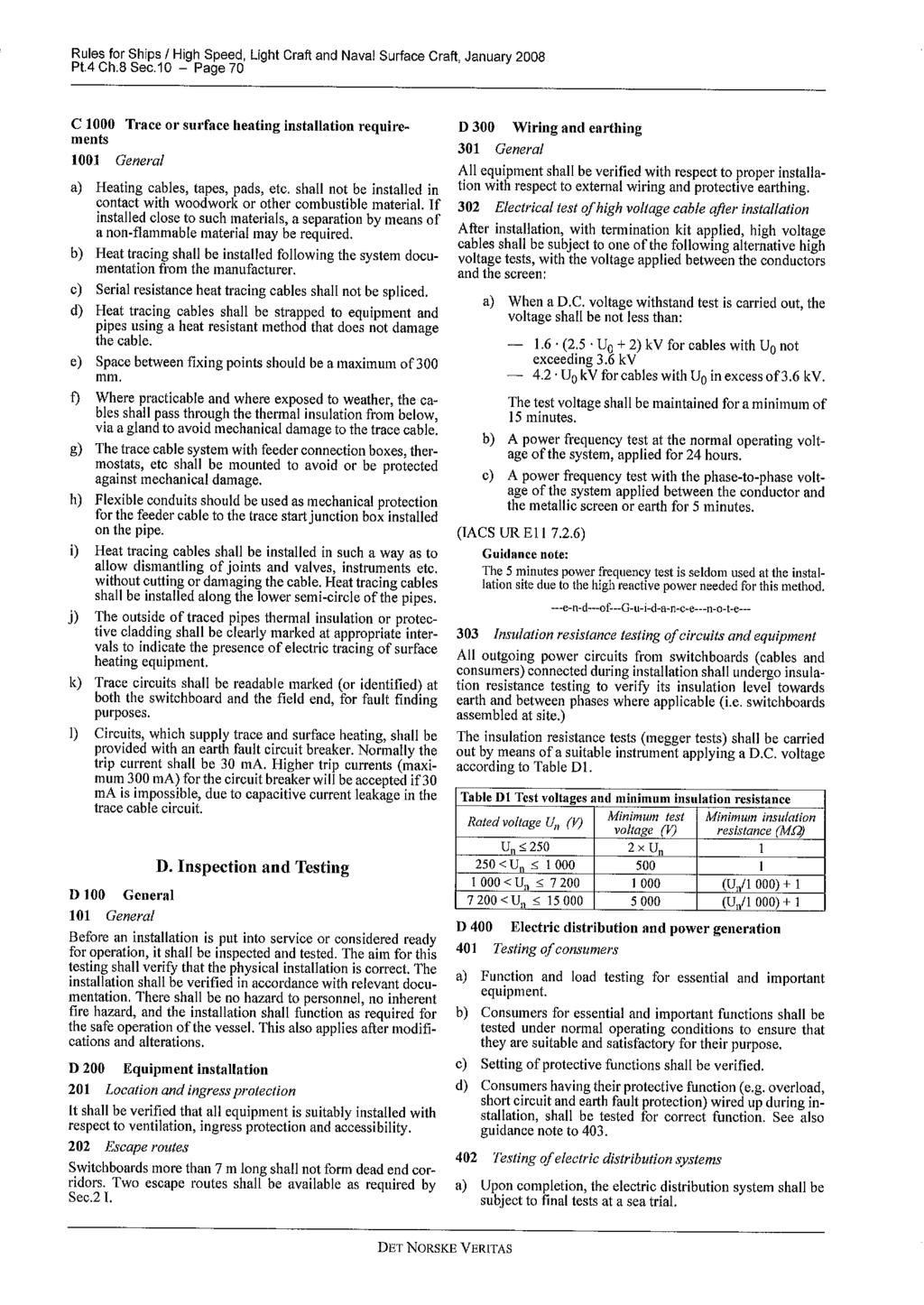
288
289
290
291
292
293
294
295
296
297
298
299
300
301 Hazardous areas Hazardous areas worldwide are classified by zone, according to the risk posed by explosive gas or dust in the atmosphere. Zone 2 / 22 Abnormal condition Presence of explosive atmosphere only by accident, but not during normal duty ( 1 H per year) Zone 1 / 21 Occasionally Incidental presence of explosive atmosphere during normal duty (1-1 H per year) CE... CE... CE... CE... CE... II 2 G EEx d(e) II 2 G EEx e II 2 G EEx p II 2 D IP65 II 2 G-D EEx d IP65 Zone / 2 Continously Permanent presence of explosive atmosphere (> 1 H per year) CE... CE... CE... CE... II 3 G EEx na II 3 D IP55 II 2 D IP65 II 3 G-D EEx na IP55 Classification of hazardous locations The definition of areas according to the presence of atmosphere are set up in EN or IEC Explosive Permanent Incidental Accidental atmosphere presence presence presence (normal operation (abnormal operation conditions) conditions) IEC (International) Zone (gas) Zone 1 (gas) Zone 2 (gas) CENELEC (Europe) Zone 2 (dust) Zone 21 (dust) Zone 22 (dust) Note: In certain countries EEx d and EEx e motors are also used in Zone 2. July 23; all equipment both electrical and nonelectrical put on the market in hazardous areas shall comply with: European Directive 94/9/EC (ATEX) Motors in accordance with ATEX directive comply with: - Low Voltage Directive 73/23/EEC amended by 93/68/ EEC (Voltage supply less than 1V) - EMC Directive 89/336/EEC amended by 92/31/EEC and 93/68/EEC - Machinery Directive 98/37/EEC (Certificate of Incorporation) Key words of ATEX Directive: - Free movement in the EU territory is ensured for any products complying with ATEX directive. - EHSRs: Essential Health and Safety Requirements needed for products used in potentially explosive atmospheres with detailed demands of manufacturer. - 1 st of July 23: The European Union has decided not to extend the transition period for the new standard relating to equipment for use in potentially explosive atmospheres, ATEX, beyond 1 st of July Article 14: Previous Directives 76/117/EEC, 79/198/ EEC and 82/13/EEC will expire on 1 st of July All national standards which are in conflict with the directive will be withdrawn. In addition to the above, all ABB's motor production units are certified to ISO 91 and ISO ABB / LV Motors / Cat. BA/Ex-motors GB 4-22
302 Marking temperatures, gas groups and hazardous areas To ensure equipment can be safety used in potentially explosive atmospheres, the hazardous areas where the equipment is installed must be known. Temperature class of equipment must be compared with the spontaneous ignition temperature of the gas mixtures concerned and its gas group must be known in specific cases (e.g. flame proof protection). Categories or classification The ATEX Directive has introduced the concept of "Categories" which is a way of expressing the capability of equipment respecting the EHSR needs for versus the Zone where the equipment is installed. Category 1 Category 2 Category 3 according to Annex 1 of ATEX used in Zone or Zone 2 according to Annex 1 of ATEX used in Zone 1 or Zone 21 according to Annex 1 of ATEX used in Zone 2 or Zone 22 Classification Category Inflammable Level of Fault Comparison with equipment substances protection protection present practice and IEC Equipment M1 Methane, dust Very high level 2 types of protection or Group I group I 2 independent faults (mines) M2 Methane, dust High level 1 type of protection Normal operation Group I Equipment Gas, vapours, Very high level 2 types of protection or Group II 1 group II mist, dust 2 independent faults Z (gas) / Z2 (dust) (surface) Gas, vapours, High level 1 type of protection Group II 2 mist, dust Habitual frequent malfunction Z1 (gas) / Z21 (dust) 3 Gas, vapours, Normal Required level of Group II mist, dust protection Z2 (gas) / Z22 (dust) Temperature classes Temperature Ignition temperature Max. permitted class for the gas/vapor temperature C equipment C T1 > T2 > 3 < 45 3 T3 > 2 < 3 2 T4 > 135 < T5 > 1 < T6 > 85 < 1 85 Grouping of electrical apparatus Group I Group II IIA, IIB, IIC Apparatus for coal mines susceptible to firedamp Apparatus for explosive atmospheres other than mines; surface industries Group II is subdivided for EEx d and EEx i -equipment according to the severity of the environment. IIC is the highest rating; a motor from one of the higher categories can also be used in a lower category environment. Marking of equipment CE marking Identification of the notified body responsible for the approval. 81 is the identification number of LCIE The European Commission mark for Ex products 81 Motor grouping: II for surface industry (I for mines) II 2 G EEx d IIB T4 Additional marking specifying the type of protection of motor Equipment category: 2 allowed for Zone 1 or Zone 21 (1 for Zone or 2, 3 for Zone 2 or 22) Atmosphere surrounding the motor: G for explosive gas (D for dust) ABB / LV Motors / Cat. BA/Ex-motors GB
303 Selection of products for hazardous areas EN Standard for Group II: Gas environments EN 514 : General rules EN 518 Flame proof enclosure «d» EN 519 Increased safety «e» EN 521 Non sparking «n» Category 2G Category 2G Category 3G II 2 G II 2 G II 3 G Product EEx d II B T4 EEx e II T3 EEx na II T3 Environment Zone 1 Zone 1 Zone 2 EN Standard for Group II: Dust environments Directive 94/9/EC (ATEX) EN : Dust ignition protection EN 514 General rules IP 6X Category : 2D IP 5X Category : 3D II 2 D II 3 D Product IP 65 - T 125 C IP 55 - T 125 C Environment EN : Dust ignition protection Zone 21 Zone 22 Zone 22 All kinds of dust Conductive dust Non-conductive dust 6 ABB / LV Motors / Cat. BA/Ex-motors GB 4-22
304 Dust Ignition protection in hazardous areas Combustible dusts is hazardous as it can form potentially explosive atmospheres when dispersed in the air. Furthermore, layers of combustible dust may ignite and act as ignition source for an explosive atmosphere. Hazardous areas with dust can be found in a variety of industries such as: - agriculture - chemicals - plastics - stock holding Selection and installation of electrical equipment To ensure equipment can be safely used in hazardous areas with dust, the following procedure should be considered before selecting a product: 1. Type of dust: - Will a cloud of dust be present around the product or - will a layer of dust build up on the product and if so, what will be the maximum thickness of the layer between two cleaning/maintenance periods? 2. Characteristics of the dust: - Is the dust electrically conductive or nonconductive? 3. Ignition temperature of the dust: - T Cl : Ignition temperature of dust in a "cloud" or - T 5mm : Ignition temperature of a 5 mm dust layer Selection and installation of product: EN Equipment category Category 1 Category 2 Category 3 (Zone 21) (Zone 21 and (Zone 22 and nonconductive dust) conductve dust) Minimum protection not applicable IP 6X IP 5X for equipment Marking temperature Type of dust Ignition Maximum surface temperature Marking temperature of temperature of motor equipment T C Cloud T CI 2/3 x T CI T C 2/3 x T CI Layer up to 5 mm T 5mm T 5mm - 75 K T C (T 5mm - 75 K) T 5mm is the ignition temperature of 5 mm layer of dust Note: In case of dust layer above 5 mm; please consult ABB. Substances (examples) Dust Wheat Barley Corn Turniprape Sunflower Sugar Lignite Sulphur T CI (cloud) 42 C 45 C 4 C 48 C 49 C 35 C 45 C 19 C T 5mm (5mm) 2 C 25 C 25 C 23 C 22 C 22 C 2 C 22 C Marking of equipment... Dust II 2 D T125 C IP 65 Surface temperature IP protection ABB / LV Motors / Cat. BA/Ex-motors GB
305 General about hazardous areas Standards Motors for hazardous areas comply with the following international standards: IEC publications 679- (2-6) and (21-2); (1999-6) European standards (latest edition) EN 514, EN 516, EN 518, EN 519, EN 521 and EN British standards BS 5 Part 16 Preamble In hazardous areas, it is the utmost importance to ensure the safe use of electrical apparatus. To this end, many countries have regulations concerning both the design and use of such apparatus. These regulations are becoming increasingly harmonized within the framework of IEC recommendations and European Standards. The hazard may be due to an explosive atmosphere composed of a mixture of gas, vapors or dusts with air. This chapter only deals with safety in explosive gas atmospheres for which European Standards exist. Flameproof enclosure EEx d and EEx de The motor enclosure shall be designed in such a way that no internal explosion can be transmitted to the explosive atmosphere surrounding the motor. The enclosure must withstand, without damage, any pressure levels caused by an internal explosion. The shape, length and gap of part assembly joints, at shaft opening, cable entries, etc., shall be designed to allow for throttling and cooling of hot gases escaping outside. The standards emphasize the impact of an explosive atmosphere (for instance, explosion pressure) over constructional requirements of such apparatus. Work on assembly devices of enclosure component parts is only permitted using prescribed tools. Cable entries must meet the requirements of this type of protection. The temperature of the motor's external enclosure should not exceed the self-ignition temperature of the explosive atmosphere of the installation area during normal Alleinschutz thermistors as sole protection (optional) The flameproof motors from ABB, frame sizes 8 to 4, have been certified for thermistors as sole protection against overload. This construction, "Alleinschutz", is available as an option, see variant codes. "Alleinschutz is a term that defines the certification of flameproof motor and protection device together. The certificate confirms that thermistors and relays will switch off the motor in case of overheating before the temperature of the motor's external enclosure exceeds the temperature marking stamped on the rating plate. Each motor ordered with thermistors as sole protection operation. For this reason, rated output depends on this rated maximum temperature for the considered area. No motor device outside the flameproof enclosure (e.g., ventilation) shall be a potential source of sparks, arcs or dangerous overheating. Variants combining two types of protection usually combine d and e protection. The most commonly used and recognized by the CENELEC European Standards is the EEx de variant. The motor is designed with an EEx d flameproof enclosure, while the terminal box features an EEx e increased safety protection. Such design combines the superior safety degree of the d type of protection with the less stringent electrical connection requirements of increased safety motors. Motors featuring dual protection are seldom encountered - such as an increased safety motor with a flameproof enclosure designated EEx e + EEx d in European Standards. will be tested, with locked rotor, up to the point where the thermistors trigger the relay to turn off the motor. At the triggering temperature, the motor has to be within the certified temperature class. The relay is included in the certificate, which means that only approved relays can be used for "Alleinschutz. Please note that sizes 315 to 4 require special technical solutions, consult ABB. 8 ABB / LV Motors / Cat. BA/Ex-motors GB 4-22
306 Increased safety design, EEx e The design of this motor type prevents the occurrence of sparks, arcs or hot spots in service (including starting and locked rotor situation), that could reach the selfignition temperature of the surrounding, potentially explosive atmosphere, in all inner and outer parts of the machine. This is ensured by applying constructional or dimensional provisions that mainly concern: specified minimum values for creepage distances and clearances use of tracking-proof isolating materials suppression of sharp angles where static electrical loads could build-up ensuring electrical and mechanical assemblies are tightly secured minimum backlash values between stationary and rotating parts (e.g., air gap, ventilation, etc.) temperature-rise limits, taking into account locked rotor, normal operation, accidental mechanical stalling of machine under the most adverse thermal conditions, i.e. when thermal equilibrium of machine is reached while in service. Temperature rise limits are to be considered for two operating aspects; one for normal operating conditions and the other under accidental stalling conditions. Temperature rise limits under normal operating conditions The expected electrical lifespan of a motor depends on its temperature rise for a given insulation class, and on the motor winding temperature, in operation, which is not homogeneous with hot spots appearing. For these reasons, a safety margin of 1 K is allowed for between windings temperature rise at rated output, as measured by the change of resistance method, and the maximum temperature rise permitted by the winding insulation class. Temperature rise limits during short circuit under accidental stalling conditions Should the machine stall while in operation, a shortcircuit current nearly equal to the starting current will develop, and stator and rotor winding temperatures will rise rapidly (see figure 1). To prevent this temperature value from exceeding the temperature level below which the apparatus should not cause the spontaneous ignition of an explosive atmosphere, protection devices must trip within a specified time (t E ). This tripping time depends on the short-circuit current level or the short-circuit current to rated current ratio (I A /I N ). Figures 2 and 3 show, for commonly used protection devices, the limiting ratio between short-circuit current inrush I A /I N and rotor stalling time t E, according to the EN and VIK. This type of protection is inappropriate for commutator machines or brake-motors which, by principle, are capable of producing arcs, sparks or hot spots. Minimum 5 s Temperature C D F Figure 2. t E s Min. value of time t E as a function of I A /I N acc. to EN 519. C B A E Figure 1. O = temperature C A = Max. ambient temperature, reference 4 C B = C = Temperature at rated load Max temperature as permitted by the insul. class D = Max limit temperature as set by the nature of the potentially explosive atmosphere E = Temperature-rise curve of motor at rated output F = Temp. rise curve under stalled rotor conditions t E = stalled rotor time t E Time Figure 3. Minimum 7 s 7 s Min. value of time t E as a function of I A /I N acc. to VIK. I A /I N ABB / LV Motors / Cat. BA/Ex-motors GB
307 Non-sparking design, EEx na, Ex na, Ex N This type of protection is allowed to be used in the hazardous area corresponding to zone 2. This design is also known as 'Non-sparking' type as the motor must be designed in such a way that no sparks can occur in normal operation, and used within the ratings specified by the manufacturer, which excludes thermal requirements due to starting or accidental stalling. Yet, EHRS's (Essential Health and Safety Requirements) stated in ATEX Directive for products installed in zone 2 have introduced new requirements on the motor design compared to previous technical report IEC (1987) used for Zone 2. These new requirements make the motor safer against the risk of spark during the start-up. However, along with the ATEX -directive, the national standards will be withdrawn and supersided by the ATEX directive 94/9/EC and the EN standards. Thus the new British standard for non-sparking is BS-EN 521. EEx na motors are not flameproof motors. They have no flamepath, and thus the enclosure groups A, B and C have no relevance. The letter "A" stands for nonsparking equipment according to EN 521. After 1 st of July, 23 it will not be allowed to put on the market any motor according to IEC in hazardous area corresponding to zone 2 in Europe. The requirements of IEC are identical to the requirements of EN 521, which proves that although CENELEC and IEC operate at two different levels, their action has a strong mutual impact in the electrotechnical field around the world. Dual certification EEx na motors in cast iron frame can also be used for Dust -applications. Following combinations are possible: CI sizes EEx na II T3 for zone 2 DIP T125 C, IP55 for zone 22 These features are possible due to the IP protection. The gases penetrate this protection, and thus the inside surface temperature class is T3 (2 C). The ingress of dust, however, is prevented and the dust determines the outside surface temperature class: T 125 C. CI sizes EEx na II T3 for zone 2 DIP T125 C, IP65 for zone 21 1 ABB / LV Motors / Cat. BA/Ex-motors GB 4-22


308 ELECTRIC MOTORS 21
309 Electric motors ELECTRIC MOTORS Information on safety and commissioning for low voltage Information on safety and commissioning for low voltage asynchronous motors In accordance with L.V. directive 73/23/EEC 1 General Information Electric motors have dangerous voltage carrying and rotating components as well as surfaces that may become hot. All work involved in the transport, connection, commissioning and regular maintenance must be carried out by qualified, responsible specialists (note VDE 15; IEC 364). improper behaviour may result in serious injury and damage to property. The applicable national, local and works regulations and requirements must be complied with. 2 Intended use These motors are intended for commercial installations. They comply with the harmonized standards of the EN634 (VDE 53) series. Utilization in areas subject to explosion hazard is not permitted, unless expressly Intended for this purpose (see additional notes). In certain special cases, for example. on use in noncommercial installations, it requirements are more strict (e.g. protection against contact with children s fingers), is it the responsibility of the customer to ensure compliance on installing the equipment. The motors are rated for ambient temperatures of -2 o C to +4 o C and site altitudes <1m above sea level. Any contradictory information. on the rating plate must be observed. The conditions on site must correspond to all rating plate specifications. Low voltage motors are components for installation in machinery in terms of the Machine directive 89/392/EEC, Commissioning must not take place until it has been proved that the end product conforms with this guideline (please note EN 624-1). 3 Transport and storage Any damage detected after dispatch should be reported immediately to the transport company and commissioning must be postponed. Tighten the eyebolts. They are designed for the weight of the motor only therefore do not attach any additional loads. If necessary, use suitable, adequately dimensioned transporting equipment (e.g. rope guides). Remove existing shipping braces before commissioning; and reuse for subsequent transport. If motors are stored, a dry, dust-free and low vibration (Vrms <.2 mm/s) environment is important (to avoid bearing standstill damage). On long-term storage, the regrease interval of the bearings is reduced. Before commissioning, measure the impedance of the insulation. It values <1kW per volt of rated voltage are measured; the windings must he dried out. When motors with roller bearings for increased cantilever force are operated the, value of cantilever force must be minimal 3% of permissible cantilever force (see catalogue). Operating with smaller cent lever force Is the cause of bearing faults. 4 Installation Ensure an even underlying surface, good foot or flange fixing and precise alignment for direct coupling. It is important to ensure that the mounting conditions do not cause resonance with the rotational frequency and the doubled supply frequency. Turn the rotor by hand and listen for any unusual grinding noises. Check the direction of rotation in the decoupled state (note section 5). Only mount or remove drive components (belt pulley, coupling, etc.) using suitable tools (heat up), and cover to shield against contact. Avoid unpermissible belt tensions (see catalogue and technical data). The balancing type is specified on the shaft end face or rating plate (H =half- and F= full-key balancing). On mounting the drive, note the balancing type! In the case of half key balancing, the protruding, visible part of the half - featherkey must be removed. 1

 the grease must be exhanged.")

 the heating effect is increased and the electromagnetic")
310 ELECTRIC MOTORS Information on safety and commissioning for low voltage A canopy is recommended for designs with the shaft end pointing downwards, and with the shaft end pointing upwards a cover must be provided by the customer to prevent foreign bodies from falling into the fan. Do net obstruct ventilation! Discharged air, also from neighbouring equipment, must not be sucked In again immediately. Checking of bearing grease must he carry out when motors are longer than 12 months storage. When storage conditions are the cause of grease depreciation (presence of condensate, consistency change) the grease must be exhanged. Grease exhange must be carry out no later than in three year interval. 5 Electrical connection Work is only permitted to be carried out by qualified specialists on the stationary motor, while disconnected and prevented from being switched on again. This also applies for the auxiliary power circuits (e.g. Anti-condensation heaters). Check that the equipment is potential-free! If the tolerance limits are exceeded that are specified in EN 634, part 1 / IEC 34-1 (voltage ± 5%, frequency ± 2%, shape of curve, symmetry) the heating effect is increased and the electromagnetic compatibility is affected. Please note the specifications on the rating plate and the connection diagram in the terminal box. Connections must be made in such a way as to ensure that a permanently safe electrical connection is maintained (no protruding wire ends) use the corresponding cable end pieces. Create a safe earth continuity connectien. Tightening torques for terminal board connections. M4 M5 M6 M8 M1 M12 M16 Tightening torque (Nm),8...1,2 1,8...2,5 2, , Clearances in air between bare live parts themselves and between bare live parts and earth must be > 5,5 mm {U rated < 69 V) - If must be ensured that the terminal box does not contain foreign bodies, dirt or humidity. Seal any unused cable entry openings against dust and water. Secure the featherkey on test operation without drive components. For motors with brakes, check that the brakes are operating perfectly before commissioning. 25mm 2 1mm 2 25mm 2 1mm 2 25mm 2 If connections are made with DIN cable lugs, band the cable lugs downwards. Connecting a single conductor with a terminal clip. Connecting two conductors of almost equal thickness with a terminal clip. If connections are made with DIN cable lugs, under the outer earthing angle. If connections are made with DIN cable lugs. 6 Operation Vibration levels of V rms <3,5mm/s{P N 15 kw) or V rms < 4,5mm/s (P N >15 kw} are quite acceptable in the. coupled state. If deviations from normal operation occur - e.g. increased temperatures, noises, vibration - the motor should be switched off in the event of doubt. Determine the causes and contact the manufacturer if necessary. Do not disconnect protective equipment, even under test operation. Under dirty operating conditions, clean the air channels regularly. Open any closed condensate water holes from time to time! 2
311 ELECTRIC MOTORS Information on safety and commissioning for low voltage For motors without regreasing facilities, bearing or grease replacement must be carried out in accordance with the manufacturer s instructions, or after 3 years, whichever is sooner. Bearings with regreasing facilities must be regreased when the motor is running. Please note the greasing plate! In the case of motors with separate ventilation, the separately-driven fan must be switched on throughout motor operation. 3
312 ELECTRIC MOTORS Information on safety and commissioning for low voltage Terminal markings MEZ 3-PHASE MOTORS MEZ 3-phase motors can be delivered from stock with rated voltages as 22/38 V - 23/4 V - 5Hz, and 38/66 V - 4/69 V - 5 Hz (from 3 kw). The motors can be operated at 6 Hz. Motor wound for 5Hz /Y 22 / 38 volt /Y 23 / 4 volt /Y 38 / 66 volt /Y 4 / 69 volt Operated at 6 Hz /Y 254 / 44 volt /Y 265 / 46 volt /Y 44 / 764 volt /Y 46 / 796 volt Lowest voltage Highest voltage W2 U2 V2 W2 U2 V2 DELTA U1 V1 W1 L1 L2 L3 STAR U1 V1 W1 L1 L2 L3 By use of star/delta starter must the lowest voltage be equal to the supply voltage. DAHLANDER-CONNECTION, 75/15 and 15/3 RPM 6 terminals Low speed High speed 2-Separate windings 1/15, 75/3 and 75/1 RPM 6 terminals Low speed High speed NOTE! Specify always the supply voltage by ordering 2-speed motors. 4
313 ELECTRIC MOTORS Information on safety and commissioning for low voltage MEZ 1-PHASE MOTORS 4 terminals 6 terminals CS CS O1 O1 Z2 O1 O2 Z2 Cb Cb L U1 Z1 U2 N U1 Z2 U1 Z2 U1 Z1 U2 O1 O2 Z2 Z1 U2 Z1 U2 L N L U1 Z1 U2 L N L N N U 1 - U 2 = Primary winding Z 1 - Z 2 = Secondary winding Cs = Starting capacitor Cb = Permanently operating capacity LUBRICATION Motorsize 4AP 56 7AA 56 4AP 63 7AA 63 7AA 71 7AA8 7AA9 7BA/7AA1 7AA112 7BA/7AA112 7AA132 7BA/7AA132 7AA16 7BA/7AA16 C18 C2 16BA. B BA. B 25 16BA. B 28 16BA. B 28 16BA. B BA. B 315 Poles 2 to 8 2 to 8 2 to 8 2 to 8 2 to 8 2 to 8 2 to to to 8 Bearing Drive end 62-ZZ C3 621-ZZ C3 621-ZZ C3 621-ZZ C3 622-ZZ C3 624-ZZ C3 625-ZZ C3 626-ZZ C3 626-ZZ C3 636-ZZ C3 628-ZZ C3 638-ZZ C C3 631 C C C C C C C C3 Bearings Non drive end 62-ZZ C3 621-ZZ C3 621-ZZ C3 621-ZZ C3 622-ZZ C3 624-ZZ C3 625-ZZ C3 626-ZZ C3 626-ZZ C3 636-ZZ C3 628-ZZ C3 638-ZZ C C3 631 C C C C C C C C3 The motors are permanently lubricated; the grease lifetime is, for CT 25 C * 2-pole motors 2 h * 4-pole motors and higher 4 h The bearing lifetime is the grease lifetime for enclosed bearings (2Z). The nominal bearing lifetime is> 1 h for a coupling drive. Lubrication. Grease change intervals. At speeds up to 18 rpm: 15 hours At speeds above to 18 rpm: 75 hours. Irrespective of the operating hours, the grease should be changed due to aging after commissioning at least on the occasion of the main inspections (approx. Every 3 years). Some of the motors have a separate nameplate with information about the bearings and the lubrication intervals. In the case of motors operating under special conditions, such as vertical motor position, frequent operation at maximum speed n max, heavy vibration, sudden load changes and frequent reversing operation, the bearing should be changed at considerably more frequent intervals than at the operating hour stated above. Type of grease for standard machines: (Fa. ESSO / UNIREX N 3). Compensatory greases must conform to DIN KL3N at least. In this case the lubrication intervals at KT> 25 C are to be reduced. Special grease are introduced on the lubricating data plate Poler Interval 4 C Interval 25 C
314 ELECTRIC MOTORS Information on safety and commissioning for low voltage Spare parts, frame size Stator - complete with winding 2. Rotor 3. Terminal box cover 4. Terminal box 5. Endshield B3, drive end 6. Endshield B5, drive end 7. Endshield B14A, drive end 8. Endshield, non-drive end 9. Anti-bump washer 1. Bearing, drive end 11. Bearing, cover 12. Bearing, non-drive end 13. Fan 14. Fan cover 15. Key 6

315 ELECTRIC MOTORS Information on safety and commissioning for low voltage Spare parts, frame size Shaft 2. Bearing cap, drive end 3. Rear endshield 4. Bearing cap, drive end internal 5. Bearing, drive end 6. Sealing of the terminal board cover 7. Terminal board cover 8. Terminal box 9. Terminal board 1. Sealing of the terminal box 11. Eye bolt 12. Stator core 13. Frame 14. Rotor core with the cage 15. Stator winding 16. Bearing, non-drive end 17. Bearing cap, non-drive end internal 18. Lubricating nipple 19. Front endshield 2. Bearing cap, non-drive end 21. Fan 22. Fan cover 23. Retaining ring (of the bearing on the shaft) 24. Key 25. Flange shield 26. Retaining ring (of the fan) 27. Key of the fan 28. Shaft sealing ring, drive end 29. Shaft sealing ring, non-drive end 7
316 Contact NORWAY SWEDEN DENMARK FINLAND BERGEN HELSINGBORG VEJLE HELSINKI Lönne Scandinavia AS Lönne Scandinavia AB Lönne Scandinavia AS Lönne Scandinavia OY Postboks 16 Kastellgatan 5 Hjulmagervej 9D Sirrikuja 3 Liamyrane 12 - Nyborg S HELSINGBORG DK-71 VEJLE FIN-94 HELSINKI N-5871 BERGEN Tel.: + 46 (42) 38 3 Tel.: Tel.: (9) Tel.: Fax.: + 46 (42) Fax.: Fax.: (9) Fax.: Service tel.: Service tel.: Service tel.: Service tel.:
317 INSTRUCTIONS FOR USE AND MAINTENANCE ROTATING ELECTRICAL MACHINES - LOW VOLTAGE
318 INSTRUCTIONS FOR USE AND MAINTENANCE ROTATING ELECTRICAL MACHINES - LOW VOLTAGE Edition 1/97
319 GB CONTENTS Page INTRODUCTION... 3 NOTE REGARDING ELECTRO-MAGNETIC COMPATIBILITY GENERAL SAFETY WARNINGS STORAGE AND INSTALLATION CONTROL STORAGE PROCEDURE Storage conditions Checking bearings Cheking insulation Operating precautions 1. 3 INSTALLATION Lifting Assembly of connecting organ Direct connection Connection by means of pulley Connection to power supply Connection of auxiliary parts 2. PUTTING INTO OPERATION INITIAL CONTROLS CONTROL OF DESIGN DATA Environmental conditions Working conditions Electric characteristics 2. 3 STARTING Earthing connection Motors with auxiliary ventilation Start up 2. 4 CONDITIONS OF USE Working features Reconditioning after long rest Anomalous conditions 3. MAINTENANCE INSPECTION Normal working Cleaning the surface Checking the supply and earthing cable Transmission elements Protection against water Drainage devices Thermal protection Unauthorized modifications Painting Reconditioning operations 3. 2 LUBRICATION Permanently lubricated bearings Bearings with lubricator 3. 3 DISASSEMBLY AND REASSEMBLING Consulting the catalogue Disconnection from power supply Placing on workstand Disassembly procedure Expedients for self-braking motors 3. 4 REPLACING THE BEARINGS Disassembly of bearings Reassembling new bearings with press Reassembling new bearings with shrinkage Checking connection of bearings Reassembling the motor 3. 5 OVERHAULS AND REPAIRS Spare parts Personnel qualification - Authorized repair shops TABLE... 7/8 2
320 INTRODUCTION The electrical machines referred to in these instructions are intended as components for use in industrial areas. The information contained in this documentation is designed for use by qualified personnel who are familiar with the current rules and regulation in force. They are not intended to replace any installation regulations issued for safety purposes. NOTE REGARDING ELECTRO-MAGNETIC COMPATIBILITY Low voltage induction motors, if installed correctly and connected to the power supply, respect all immunity and emission limits as set out in the regulations relating to electromagnetic compatibility (EMC Generic Standard for industrial environments). In the case of supply by means of electronic impulse (inverters, soft starters etc.), all verifications and any modifications, necessary to ensure that emission and immunity limits, as stated within the regulations, are respected, are the responsibility of the installer.. GENERAL SAFETY WARNINGS DANGER Rotating electric machines are dangerous. Consequently: - improper use - removal of protection and disconnection of protection devices - lack of inspection and maintenance can cause serious harm. The personnel must be informed of any danger caused by contact with: - live parts - rotating parts - hot surfaces. In normal working conditions the motor exceeds 5 C. The safety manager must ensure and guarantee that: - the machine is moved, installed, put in service inspected, maintained and repaired only by qualified personnel, who should have: - specific technical training and experience - knowledge of technical standards and applicable laws - knowledge of general safety regulations as well as national, local and installation regulations - ability to recognize and avoid all possible dangers. Work on the electric machine should be carried out upon authorization of the safety manager after having ensured that: a) the motor has been disconnected from the power supply and that no parts of the motor including auxiliary parts are live b) discharge of the condenser has been done for single phase motors c) the motor is completely stopped and there is no danger of accidental restarting d) the right precautions against faulty braking operations have been taken for self-braking motors where thermal protection with automatic reset is used care must be taken to ensure automatic restart cannot occur. Since the electric machine referred to is intended to be used in industrial areas, additional protective measures must be taken and guaranteed by the person who is in charge of installation where more stringent protective measures are needed. 1. STORAGE AND INSTALLATION 1.1 Control 1.2 Storage procedure The motors are shipped ready for installation. Upon receipt remove packaging and turn the shaft to check the motor has not been damaged, also check all physical aspects of the machine for damage. In the case where the machine is damaged an immediale notification must be given in writing by the storeman and the representative of the carrier to CEMP INTERNA- TIONAL within 3 days If the motors are not used immediately, they should be stored in a clean, dry and temperate environment free of vibrations and protected from the weather. (If stored below -15 C, and before starting, the motor temperature must be restored to the permissable working temperature range (i.e. -15 C 4 C). In this case, it is necessary to specify these particular storage conditions during the ordering stage so that proper precautions can be taken during building and packaging When the motors are stored properly, bearings do not need maintenance. However, it is a good idea to turn the shaft by hand every three months. After storage for over one year motors with unshielded bearings (usually such motors have a lubricator and bear a lubrication plate), it is advisable to check the condition of the lubrication and motor components. 3
321 1.2.3 Before installation check the motor windings using the appropriate instruments to ensure the condition of the insulation between phases and between phase and earth are of the corrects resistance values. Do not touch the terminals during and immediately after measuring as they are live. If the insulation resistance value is less than 1 megaohm, or after storage in a damp environment, the motors must be put to dry in an oven for about 8 hours by gradually bringing the temperature up to 1 C. To ensure that the dampness has been completely expelled, the motors must be disassembled All operations listed above must be carried out by qualified personnel. In case of flameproof motors it is necessary: - to be very careful that the flame-proof characteristics are not altered - to have the procedure described in point carried out by authorized repair shops - to understand dismantling or opening of the motor during the warranty period without authorization of CEMP INTERNATIONAL may invalidate the warranty. 1.3 Installation Work on the electric machine must be carried out when the machine has stopped and been disconnected from the power supply (including auxiliary parts, such as anticondensation heaters) Lifting Before using the lifting rings make sure they have been tightened. The lifting rings are big enough to bear the weight of a single motor, therefore they must not be used to lift the equipment connected to the motor. In environments where the temperature is below -2 C, these lifting rings should be used with caution as they could break at low temperatures and cause damage Fitting devices to shaft Fitting if pulley, coupling or gear to the motor shaft must be carried out with care to ensure no damage is caused to the bearing. Remove the protective paint finish from the shaft and smear with oil then fit the device heating before fitting if possible to ensure an easy fit. Any component that is assembled on the motor shaft must be accurately balanced. Connection with fitments not balanced properly causes anomalous vibrations during operation that jeopodises proper working of the motor and drastically reduces its life Direct connection Use couplings that have been made and balanced perfectly align the motor shaft and the operating machine precisely. Inaccurate alignment may cause vibrations and damage to the bearings or breakage of the shaft end Connection by means of pulley Check that alignment with the pulley of the operating machine has been carried out perfectly. The tension of the belts must be enough to avoid slipping. Excessive tension of the belts causes harmful radial loads on the motor shaft and bearings, reducing their life. It is advisable to assemble the motor on beltstretching slides in order to regulate tension of the belts exactly. Connection with belts must be such as to avoid accumulation of static charges in the moving belts which could cause sparks Connection to power supply Use cables with sufficient section to bear the maximum current absorbed by the motor, avoiding overheating and/or drops in voltage. Connect the cables to terminals by following the instructions on the plate or on the diagram included in the terminal box. Check that terminal nuts are tightened. Connections to the terminals must be made in order to guarantee safe distances between live uncovered parts. Do the earthing by using the screw located inside the terminal box. Flame-proof motors are provided with a second earth stud located on the motor casing outside the terminal box. Earths must of sufficient size and installed according to relevant standards. The area of contact of connections must be cleaned and protected against corrosion. When the cable inlet is made by means of a cable gland, it must be chosen properly in relation to the type of plant and type of cable used. The cable gland must be tightened so that the retaining rings create the pressure necessary to: a) prevent transmission of mechanical stress to the motor terminals b) to ensure the mechanical (IP degree) protection of the terminal box. For flame-proof motors the cable inlet must be made by complying with the regulations in points 12.1 and 12.2 of the standard EN Apertures not used must be closed in accordance with specifications in point 12.5 of the same standard. When reassembling the terminal cover, make sure that if there is a seal, it is in the right place. Flame-proof motors do not have a seal so before reassembling the terminal box it is necessary to replace the layer of grease. The terminal box cover must be tightened to ensure it is properly sealed Connection of auxiliary parts (Table B) a) thermal protection Check which type of protection is installed before making connections. If thermistors (PTC) are used, it is necessary to utilize a suitable relay. b) anti-condensation heaters If the motor is fitted with anti-condensation heaters, their power supply must be separated from that of the motor, using the terminals housed in the terminal box. WARNING: the supply of the heater is always monophase and the voltage is different from that of the motor. Check that it corresponds to the one indicated on the plate. c) auxiliary ventilation Connect the supply of the auxiliary ventilation motor separately from that of the main motor. WARNING: use a device that allows starting and operation of the main motor only when the auxiliary fan is working. d) all the above-mentioned operations must be carried out by following the instructions shown on the diagrams of connection provided with the motor. 4
322 2. PUTTING INTO OPERATION It is the responsibility of the installer to establish the motor's fitness to be used in a certain plant, after analysing the characteristics of danger existing in the installation area with respect to current provisions of the law and to those issued for safety purposes. 2.1 Initial Controls Before starting the motor it is important to check that: a) installation has been carried out properly b) the bearings have not been damaged during installation c) the motor base is sturdy enough and the foundation bolts have been tightened d) the design data corresponds to those given on the plate and in the technical documentation The electric motor is a component made to be mechanically connected to another machine (single or part of a plant). Consequently, it is the responsibility of the person who looks after installation to guarantee that during operation there is an adequate degree of protection for people or things against the danger of accidental contact with moving parts. 2.2 Control of Design Data Make sure that the motor is suited for use in the working conditions foreseen and check the following: Environmental conditions a) environmental temperature: standard motors may work between -15 C and +4 C b) altitude: normal motors have been designed to work between and 1. m above sea level c) protection against the presence of harmful agents like: sand, corrosive substances, dust and/or fibre, water, mechanical stress and vibrations d) mechanical protection: installation inside or outside considering the harmful effects of the weather, the combined effect of temperature and humidity and the formation of condensation e) adequate space around the motor particularly on the fan side to allow proper ventilation f) motors mounted in the vertical, shaft down require a protective cowl over the fan inlet g) any danger of explosion or fire Working conditions a - operation type: the motors are normally for S1 type continuous operation b - load type: carefully evaluate machines with high moments of inertia and the relative starting times c - for motors intended for operation in hazardous areas (EEx-d or EEx-e) the motor type and temperature classification must comply with the area rating When there is an X on the plate near the certificate number, it is necessary to check on the certificate which additional conditions are required for proper working. d - for self-braking motors see the special applications envisaged in the relative catalogue Electric characteristics a - voltage and frequency should correspond to those on the plate b - motor power should be adequate as required by the load c - power supply protections against overloads and/or short circuits should be adequate for nominal currents and starting currents d - for connection to control circuits follow the connection diagram supplied with motor (Table A) Abnormal working conditions must always be defined when placing order to ensure that the site conditions are not prejudicial to the proper operation of the machine 2.3 Starting Before starting the motor ensure that the incoming supply cables are connected correctly For motors with forced ventilation by means of external ventilation make sure that the motor starter is interlocked with the, contactor of the external ventilator to ensure the fan is operational When all previous checks have been made satisfactorily, the motor may be started. Unless oterwise started all motors can be direct on line started. Save when otherwise indicated, all motors are fit for direct starting. If you intend to start the motor by means of static starters, rheostats or the star-delta system, they must be chosen and set property to avoid incorrect functioning of the motor. 2.4 Conditions of Use Once the motor has started it is necessary to check that during operations the working conditions remain within the limits envisaged, and that the following does not occur: a) overloading b) dangerous rise in environmental temperature c) excessive drop in voltage E very time there is a change in the working conditions, it is necessary to check that the complete fitness of the motor has been maintained for the new operating conditions. For example: - variation in working cycle - the function of the motor has not altered - moving of the motor to a different environment (from outside to inside) - moving of the motor from a low temperature environment to one with a higher temperature Before starting the motor after a long resting period, repeat the controls described in section 1. When supplied, heater must not be energised when the motor is running The motor must be used solely for applications it was designed for and must be utilized and controlled complying with the precautionary standards. If the machine shows anomalous working characteristics (greater absorption, increase in temperature, noisiness, vibrations), inform the personnel in charge of maintenance immediately. 5
323 3. MAINTENANCE Any operation on the motor must be carried out with the machine stopped and disconnected from the power supply (including auxiliary circuits, especially the anticondensation heaters). Maintenance of the original characteristics of electric machines over time must be ensured by a schedule of inspection, maintenance and setting up managed by qualified technicians. The type and frequency of maintenance depends on environmental and working conditions. For flame-proof motors, apart from specifications in this document, refer to the CEMP INTERNATIONAL manual entitled MAIN- TENANCE AND REPAIR GUIDE FOR ELEC- TRIC FLAME-PROOF MOTORS. As a rule, it is recommended that the first inspection is made after about 5 hours of operations (or, within 1 year), while subsequent inspections should follow the schedules established for lubrication and general inspection. 3.1 Inspection Check that the motor works normally without anomalous noise or vibrations. If it does not, locate the cause of the anomaly Make sure that the ventilation is not obstructed. Clean the motor by removing any dust or fibre deposits from the fins and from the fan cover Check that the supply cable does not show signs of wear and that the connections are tight. Make sure that the earth and supply cables are not damaged Check that the transmission elements are in perfect condition and that the screws and nuts are tight When the motor is installed in a very damp environment or is subject to drips of water, check regularly that the seal and retaining rings and any protective devices work efficiently. Ensure that there are no infiltrations inside the casing or terminal box The motors furnished with drainage devices should be checked and cleaned regularly so that such devices continue to work properly Make sure that thermal protections have not cut out and have been set properly. The right selection and setting of thermal protections for EEx-e motors is essential to guarantee the temperature class and safety against the danger of explosion Check that no modifications have been made that alter the electric and mechanical operation of the motor When the motor is installed in an environment where there are corrosive agents it is recommended to paint the motor itself to protect the outer surfaces from corrosion if necessary Every irregularity or anomaly found during inspection must be fixed immediately. 3.2 Lubrication Motors with shielded or sealed bearings (type ZZ or 2RS) do not require lubrication. Therefore, if used properly, they do not require maintenance Motors with unshielded bearings are furnished with lubricators. The interval of time between lubrications depends on the type of grease, environmental temperature, overheating of the motor and type of operation the motor carries out. The table C shows the intervals foreseen for 7 C as a working temperature of the bearings in normal operating conditions. It is recommended to use a good quality lithium based grease with great penetration capacity and high dropping point like Athesia 3 by IP, Beacon 3 by Esso or Avana 3 by Shell. If the velocity is different from the one given in the table, the intervals must be modified in inverse proportion. Eg. bearing 6314 at 1.8 RPM 15 1 = x 355 h = 295 h 18 Regardless of working hours, the grease must be renewed after 1 or 2 years or during a complete overhaul. When the motor is furnished with a lubrication plate, refer to the dates shown on it. 3.3 Disassembly and Reassembling the Motor All operations must be carried out bearing in mind health and safety regulations Before working on the motor it is advisable to consult the relevant catalogue and have all the tools ready Before proceeding with the disassembly the motor must be disconnected from the power supply. Make sure that the power is off and disconnect supply cables and auxiliary cables when there are any In order to work on the motor satisfactorily it should be removed from its mounting and placed on a work bench Take off the fan cover by removing the fixing screws. Using an extractor remove the cooling fan. Remove the end shields and withdraw the rotor being careful not to damage the windings. Precautions must be taken with flameproof motors so that the spigots on the frame and the end shields are not damaged. When the motor is disassembled and before it is reassembled it is necessary to protect the various components (particularly the bearings and windings) to avoid damage caused by dust or knocks For disassembly of self-braking motors follow the instructions shown in the relative catalogue. 3.4 Replacing the Bearings Remove the bearings using an extractor. Ensure the respective housings have not been damaged then fit the new bearings - these must be the same type as the old ones To fit the new bearings it is advisable to use a press and a sleeve which rests on the inner ring and must not put pressure on the outside ring of the bearing. The surfaces of the relative housings should be oiled slightly If the facilities are available, however, it is recommended that the bearings are heated to 9-1 C and fitted quickly to the shaft. Use a brass sleeve resting on the internal ring of the bearing and if a press is not available use a mallet After the assembly has been finished the internal rings of the bearings must rest against the relative shaft shoulders Before reassembling, clean the internal parts of the motor carefully and check that the components have not been damaged. Renew the layer of grease where needed on the abutting spigots and proceed with the reassembling. For more detailed information on the proper procedure, consult the catalogues relative to the various types of motors. 3.5 Overhauls and Repairs When needed, all motor components should be replaced by original spare parts. To request spare parts use the nomenclature shown in the catalogues and always give: - motor type - serial number - year built Overhauls and repairs must be carried out by trained personnel who guarantee restoration of the motor to its original conditions, we recommend that you contact an authorised repair agent. For further information please contact our sales department. 6
324 Connecting diagrams - Table A Connection for single speed motors: Y-Connection U1 Connection- U1 W2 U2 V2 W2 U2 V2 U1 V1 W1 U1 V1 W1 W1 V1 L1 L2 L3 W1 V1 L1 L2 L3 Number of pole: 2, 4, 6, Synchronous speed at 5 Hz: 3, 15, 1, Two separate windings for two speed motors: L1 L2 L3 High Speed W2 W2 U2 V2 Low Speed U1 W2 U2 V2 U1 V1 W1 U1 V1 W1 V2 U2 W1 V1 L1 L2 L3 Number of pole: 2/6, 2/8, 4/6, 6/8... Synchronous speed at 5 Hz: 3/1, 3/75, 15/1, 1/75... Dahlander system for two speed motors, constant torque: High Speed W2 L1 L2 L3 W2 U2 V2 Low Speed U1 W2 U2 V2 V2 W2 U1 W1 U1 V1 W1 U1 V1 W1 V2 V1 U2 W1 U2 V1 L1 L2 L3 Number of pole: 2/4, 4/8 - Synchronous speed at 5 Hz: 3/15, 15/75 Dahlander system for two speed motors, quadratic torque: L1 L2 L3 High Speed W2 W2 U2 V2 Low Speed U1 W2 U2 V2 U1 W1 V1 U1 V1 W1 V2 W2 U2 U1 V1 W1 V2 U2 W1 V1 L1 L2 L3 Number of pole: 2/4, 4/8 - Synchronous speed at 5 Hz: 3/15, 15/75 Single phase motors connecting diagram µf Right rotation Starting w. V2 W2 µf V2 Left rotation V2 Starting w. W2 V2 U1 W1 U1 W1 W2, U1 Main w. W1 L1 L2 U1 Main w. W1,W2 L1 L2 7
325 Additional terminal marking - Table B Identification number Additional terminals for Thermistor PTC Thermistor PT Normally closed bi-metallic switch Normally open bi-metallic switch 7-71 Space heater Forced ventilation 5-6 Tachogenerator and others Lubrication intervals in hours for unshielded bearings - Table C Bearings Amount of Grease in Grammes RPM RPM RPM RPM , , NU 39 12, / NU NU NU NU / NU / NU / NU
326 Programma di vendita Sales programme Programme Lieferprogramm MOTORI ANTIDEFLAGRANTI EEx-d - EEx-de gruppo I-IIA-IIB-IIC classe T3-T4-T5-T6 trifasi, monofasi con freno MOTORI A SICUREZZA AUMENTATA EEx-e classe T1-T2-T3 MOTORI NON SPARKING EEx-nA MOTORI CHIUSI CON VENTILAZIONE ESTERNA CEI/IEC trifasi, monofasi speciali su specifiche del cliente ELETTROPOMPE CENTRIFUGHE ad immersione orizzontali ELETTROPOMPE CENTRIFUGHE ANTIDEFLAGRANTI EEx-d FLAME PROOF MOTORS EEx-d - EEx-de group I-IIA-IIB-IIC class T3-T4-T5-T6 threephase, singlephase with brake INCREASED SAFETY MOTORS EEx-e class T1-T2-T3 NON SPARKING MOTORS EEx-nA TOTALLY ENCLOSED FAN COOLED IEC MOTORS threephase, singlephase special to customs own design CENTRIFUGAL PUMPS immersible horizontal CENTRIFUGAL PUMPS WITH FLAME PROOF MOTOR EEx-d MOTEURS ANTIDEFLAGRANTS EEx-d - EEx-de groupe I-IIA-IIB-IIC classes de température T3-T4-T5-T6 triphasés - monophasés avec frein MOTEURS A SECURITE AUGMENTEE EEx-e classes de température T1-T2-T3 MOTEURS NON SPARKING EEx-nA (anti-étincelle) MOTEURS IP 55 CEI-IEC AVEC VENTILATION EXTERIEURE triphasés - monophasés spéciaux sur plan du client ELECTROPOMPES CENTRIFUGES avec corps immergé horizontales ELECTROPOMPES CENTRIFUGES ANTIDEFLAGRANTES EXPLOSIONS- GESCHÜTZTE MOTOREN EEx-d - EEx-de Gruppe I-IIA-IIB-IIC Klasse T3-T4-T5-T6 Dreiphasen, Einphasen Ausführung mit Bremse ERHÖHTE SICHERHEITSMOTOREN EEx-e Klasse T1-T2-T3 FUNKENFREIE MOTOREN EEx-nA VOLLGEKAPSELTE LUFTGEKÜHLTE IEC MOTORE Dreiphasen, Einphasen Ausführung Sonderausführung nach Kundenbedarf FLIEHKRAFTPUMPEN Tauchbar Horizontal FLIEHKRAFTPUMPEN MIT EXPLOSIONSGESCHÜTZ- EM MOTOR EEx-d Le descrizioni e/o caratteristiche tecniche del presente catalogo non sono impegnative. La CEMP INTERNATIONAL si riserva il diritto e la facoltà di apportare modifiche in qualsiasi momento, senza preavviso. Descriptions and/or technical features listed in this catalogue may not be considered as binding. CEMP INTERNATIONAL reserves the right to make alterations at any time without prior notice. Dans le souci d'améliorer continuellement nos produits, certaines données de notre catalogue peuvent être modifiées par la CEMP INTERNATIONAL sans préavis. Die Beschreibung und oder technische Eigenschaften die in diesem Katalog angegeben sind, dürfen nicht als verbindlich angesehen werden. CEMP INTERNATIONAL behält sich das Recht vor, ohne Mitteilung, Abweichungen und Änderungen jederzeit vorzunehmen. CEMP International SpA I 23 SENAGO - MI - Via Piemonte, 16 Telefono: (int. +39) Fax (int. +39) cemp@cemp.it

327 Fast customer response time: We aim to respond your request within 24 hour Customer support & service: Our team of engineer supports you with qualified answer or on site support if necessary. Tel: Fax: Mail: office@nyborgfan.comcom Wide range of standard applications on stock. Our organisation can adapt customers needs, and if precarious, we can deliver spareparts or standard souloutions in just a couple of days. When ordering spareparts p we need serial number for original fan, for quick handling. Please Contact Purchase & Service Manager: Arild Brunstad, arild.brunstad@nyborgfan.com
328 References Axial Fans Centrifugal Fans Explosion Proof Fans for Hazardous Area Mist Eliminator Weather Louvers Dampers Ventilation Cowls References NORWEGIAN SHIPYARDS. PACKAGE DELIVERIES. COMPLETE DELIVERY OF FANS AND WEATHER LOUVERS PACKAGES. Ship yard Y.No Dilivered Equipment Type of Vessel Aukra Bruk AS Aukra Ferry Aukra Aukra Industrier AS Tårnsund - Aukra American Express Fabric trawler Antartic Longlining Artic longliner Petur Jonsson Stern trawer Rieber Shipping Seismic vessel A.Utkilens Rederi Chemical tanker A.Utkilens Rederi Chemical tanker S.Mørkster Shipping Supply vessel S.Mørkster Shipping Supply vessel Petur Jonssong Factory trawler Anders Utkilens Rred tdw Che.T Anders Utkilens Rred tdw Chem.T Anders Utkilens Rred tdw Chem.T. Brattvåg Skipsverft Austvik - Brattvåg Supply vessel 43 - S. v 44 - S. v 45 - S. v KS Dianne op. Ltd Supply vessel Antartic Longlining Artic longliner Antartic Longlining Artic longliner District Offshore Supply Ship Johannes Østensjø d.y AS Supply Ship Aker RGI Aker RGI ASA Pacific Partn. Mar Newbuilding Newbuilding Olympic Offshore RTMT6 Supply S Multi Purp.Supply Multi Purp.Supply y N-6239 SYKKYLVEN TEL: FAX
329 References Axial Fans Centrifugal Fans Explosion Proof Fans for Hazardous Area Mist Eliminator Weather Louvers Dampers Ventilation Cowls References NORWEGIAN SHIPYARDS. PACKAGE DELIVERIES. COMPLETE DELIVERY OF FANS AND WEATHER LOUVERS PACKAGES. Ship yard Y.No Dilivered Equipment Type of Vessel Brødrene Langset AS Nybo Holding Fishing Trawler Lyngstad Båtbyggt AS 1999 Voldnes Seismic Research V. Raudeberg Båtservice Holdingt AS Anders Utkilen Chemical tanker Mandal M/S Vesta Ferry Egersund Mek. Verkst Gollenes Fishing Vessel Eid Verft A/S Eid Ferry Azalea - Eide Contracting Tuna West Fishing Vessel Eidsvik Skipsb. AS Paula Trawler Uskedalen Sæbjørn Purse Seiner Fiskerstrand Verft AS Nordtørn - 27 Joffre Skarhaug Nonhammer - 3 Leinefisk Sætring Fernando Geir Husby Senior Ny Geir Fishing vessel Ferry Line Trawler y N-6239 SYKKYLVEN TEL: FAX
330 References Axial Fans Centrifugal Fans Explosion Proof Fans for Hazardous Area Mist Eliminator Weather Louvers Dampers Ventilation Cowls References NORWEGIAN SHIPYARDS. PACKAGE DELIVERIES. COMPLETE DELIVERY OF FANS AND WEATHER LOUVERS PACKAGES. Ship yard Y.No Dilivered Equipment Type of Vessel Flekkefjord Slipp & Gecoship a.s Seismic vessel Naskinfabrikk as 145 Øgurvik H.F Factory trawler Flekkefjord Geco Diamond Seismic vessel 152 Norad Research vessel Hrønn HF Fabric trawler Newbuilding Pelagic trawler 158 N. b. P.t Serene Fish. Co Pelagic trawler Lauritz Eidesvik Supply ship Newbuilding Newbuilding Newbuilding Fishing trawlers Newbuilding Fishing trawlers BLBM Ltd Fishing Trawler Antares Fish.Co Purse seiner/trawler Antares Fish.Co Purse seiner/trawler M/S Antattic/Eamon Mc. Hugh/Fishing Trawler P&J Johnstone Ltd Pelagic Trawler M/V Quantus Ltd Pelagic Trawler M/V Serene/ Serene Fishing C. Fishing Trawler Geco Angler/Remøy Sh. Research vessel Rieber Shippingh. Seismic RV MPSV Fosen Mek. Verkstad Vela - Fosen Lynx - 17 Fjell Fjord - 19 Porsøy Nordvær - 21 Rogaland Lomur Blikur Newbuilding - AS Haugesund Slip Santa teresa - Haugesund Hellesøy Nordfjord Nordfjordeid Hellesøy Th.Skipsbyggeri AS Løfallstrand Sævik Supply Shipping Superior MPS Offsh Olympic Shipping AS UT722 Supply Sh. y N-6239 SYKKYLVEN TEL: FAX
331 References Axial Fans Centrifugal Fans Explosion Proof Fans for Hazardous Area Mist Eliminator Weather Louvers Dampers Ventilation Cowls References NORWEGIAN SHIPYARDS. PACKAGE DELIVERIES. COMPLETE DELIVERY OF FANS AND WEATHER LOUVERS PACKAGES. Ship yard Y.No Dilivered Equipment Type of Vessel Hjørungavåg Mek.V Brestingsson - Hjørungavåg Reinøy Gulen Container vessel 51 Holen mek Verksted Varøy - Langevåg - C.v. Karmøy Mek. Verk Chris Andra - Karmøy Taits - Kværner Fjellstrand AS Nordic Jet Line Jumbo Cat 6m Omastrand Jumbo Cat 6m Kværner Kimek Vestliner Jumbo Cat 6m Kirkenes Fiskeriselskap K/S Kværner Kleven Florø Kværner Kleven Andenes Havfisk Stern Trawler Leirvik Remøy Sea Group Supply ship Kværner Kleven Erikson Crystal - 16 Erikson Artic Erikson Cooler - 18 Erikson Frost - 19 Newbuilding Newbuilding Eidesvik & Co AS VS492 Supply S. y N-6239 SYKKYLVEN TEL: FAX
332 References Axial Fans Centrifugal Fans Explosion Proof Fans for Hazardous Area Mist Eliminator Weather Louvers Dampers Ventilation Cowls References NORWEGIAN SHIPYARDS. PACKAGE DELIVERIES. COMPLETE DELIVERY OF FANS AND WEATHER LOUVERS PACKAGES. Ship yard Y.No Dilivered Equipment Type of Vessel Kystvågen Slip & Cecilia Trosca - Båtbyggeri Øyliner - 38 Max Kåre Langsten Slip & Avantgard - Båtbygger 135 Ocean Rover Fabric trawler Hvitanes Petro geo services Research vessel American Seafood Co Factory trawler Sealord Trawler Farstad Shipping Supply Ship Petro geo services Seismic Ramform PGS Seismic Ramform Farstad Shipping ASA UT741 MPS Vessel PGS Seismic Ramform PGS Seismic Ramform N.b. UT741 MPS Vessel Mjellem & Karlsen Bergen Rem Searcher Newbuilding Seismic Vessel Baruna Jo Research Vessel Myklebust Mek Ferry Gursken Sævik Supply ASA Supply Ship Newbuilding Supply N.b. UT-741 MPS Vessel N.b. Supply N.b. Stern Trawler N.b. Stern Trawler y N-6239 SYKKYLVEN TEL: FAX
333 References Axial Fans Centrifugal Fans Explosion Proof Fans for Hazardous Area Mist Eliminator Weather Louvers Dampers Ventilation Cowls References NORWEGIAN SHIPYARDS. PACKAGE DELIVERIES. COMPLETE DELIVERY OF FANS AND WEATHER LOUVERS PACKAGES. Ship yard Y.No Dilivered Equipment Type of Vessel SIMEK AS Flekkefjord Far Sea Anch.handl./Tug/Sv 76 Far Sky d.o Herjolfur Pass./car ferry Samherji H.F Freezer trawler Jih. Østensjø Escort tug Jih. Østensjø Escort tug Jih. Østensjø Escort tug Fishing Co Pelagic trawler Alfons Håkans Supply Ship Lunar Fishing Solstad Shipping Supply Ship M/V Maersk Battler Supply/Anchor H M/V Maersk Beater d.o M/V Maersk Boulder d.o M/V Maersk Blazer d.o Havila Lista Supply Ship Newbuilding Trawler Havila Hildra Supply Ship Slipen Mek. as Stamsund - sandnessjøen Søviknes Verft as Sævik Supply Supply vessel Søvik Farstad Shipping Supply vessel Newbuilding Arctic shrimp trawler 113 N.b Ocean Prawns Artic trawler Niisa Trawl Arctic shrimp trawler Aker RGI Trawler Aker RGI Trawler newbuilding N.b Puretank Reder Chemical tanker Frendtrawl K/S Factory trawler Ulstein Hatlø AS Northern Eagle Fabric trawler Polar Circle - Ulstein International Seattle Fabric trawler y N-6239 SYKKYLVEN TEL: FAX
334 References Axial Fans Centrifugal Fans Explosion Proof Fans for Hazardous Area Mist Eliminator Weather Louvers Dampers Ventilation Cowls References NORWEGIAN SHIPYARDS. PACKAGE DELIVERIES. COMPLETE DELIVERY OF FANS AND WEATHER LOUVERS PACKAGES. Ship yard Y.No Dilivered Equipment Type of Vessel Ulstein Verft AS Ulstein Sverre Farstad Supply vessel Sverre Farstad S.v Erasmusgracht Container ship 244 d.o dry bulk d.o 13. tdw Newbuilding Tug/supply vessel Maersk Cable laying vessel Sævik Supply Sh. Supply ship Swire Pacific Supply ship 252 Offshore ships d.o 253 d.o d.o Swire Pacific Offsh. Supply/Anchor H.å Solstad Shipping Supply ship Newbuilding UT73 MPS Vessel UT742 Supply S Swire Pacific Offsh. Supply/Anchor H Swire Pacific Offsh. Supply/Anchor H N.b UT742 Supply S Ulstein Mek. Verkst Newbuilding Catamaran Hareid UMOE Sterkoder Bror Husell Chatering Sto-Ro-Contain Kristiansund N Rederi AB Engship Sto-Ro-Contain Rederi AB Engship Sto-Ro-Contain Newbuilding MPS Vessel Westcon AS Newbuilding Fishing Vessel Ølensvang y N-6239 SYKKYLVEN TEL: FAX
335 References Axial Fans Centrifugal Fans Explosion Proof Fans for Hazardous Area Mist Eliminator Weather Louvers Dampers Ventilation Cowls References OFFSHORE off air handling units for Ekofisk 2/4 T PPCON -6 off centrifugal fans for Ekofisk 2/4 C -1 axial fan for Eldfisk 2/4 A -2 off axial fans for Ekofisk 2/7 A PPCON off centrifugal fans for Ekofisk 2/4 C PPCON -1 off fan, cyclone and filter unit for Veslefrikk B Statoil -1 off air handling unit for Ekofisk CCC building PPCON -2 off air handling unit for Ekofisk H7&B11-2 off kitchen extract unit for Ekofisk H7&B11-1 off fan and cyclone unit for Ekofisk PPCON Balancing dampers packaging for Brage projekt Hydro -3 off air handling units for Petroland/KGD sat. platf. Elf -1 off air handling unit for Draugen DMS Shell -2 off air handling unit for LQ-Statfjord C Statoil -1 off air handling unit for Ekofisk 2/4, gas lift project PPCON -2 off air handling units for Ekofisk 2/4 utility deck PPCON -1 off centrifugal fan for statfjord C Statoil off fan for West Alpha Smedvik Drilling -2 off centrifugal fans & dampers for Ekofisk H7&B11 PPCON -1 off centrifugal fan for Vallhall Platform Amoco -2 off air inlet/outlet boxes with fans. Container Maskin K Lund -1 off fan unit for Frigg Platform Elf -2 off axial fans for Ekofisk 2/4T PPCON -1 off centrifugal fan and damper for Ekofisk 2/4D PPCON -4 off balancing dampers for Frigg Platform Elf -1 off fan unit for Gyda Platform BP -6 off axial fans for Ula, gas turbine room BP -8 off various dampers/louvres for Ekofisk 2/4T PPCON Weather louver package for heidrun projekt Conoco -Various HVAC fans and dampers for Ekofisk 2/4P PPCON -1 off air handl. unit/europipe Dev. Proj./16/11 E-platf Statoil -5 off separate fans, Europipe Dev. Proj/16/11 E-Platf Statoil -6 off airhandlings units. Troll Ph 1, drilling module Shell -12 off axial flow fans Statfjord C, Condenser/Contr.r Statoil -4 off hydr. driven axial fans, Fan Coil Units TTC Norge off centr. fan Hod Platform, Shelter Module Amoco -11 off centr. fan Ekofisk 2/4 Hotel/upgrade Phillips off airhandlings unit Ekofisk 2/4X Phillips Axial fans & Cowls, metanol Project HVAC/Tjeldbergodden y N-6239 SYKKYLVEN TEL: FAX
336 References Axial Fans Centrifugal Fans Explosion Proof Fans for Hazardous Area Mist Eliminator Weather Louvers Dampers Ventilation Cowls References OFFSHORE off Fan Skid, Plugs & Abandon Rig MHVAC/PPCON off Airhandling Unit MHVAC/Byford Dolphin -1 off Mud Fan MHVAC -2 off Fan Skid, Plugs & Abandon Rig MHVAC/PPCON -Fan skid f. driller s Cabin Simex/HITEC -6 off fan skid, Cooling El Motors for Drawworks HITEC HVAC Equipment for Drilling Facilities HITEC ASA NAVIS - Explorer 1 - Samsung SY -Fan Skid f. Driller s Cabin Simex AS/HITEC ASA -2 off Fan Skid f. Cooling El Motors HITEC ASA for Drawworks -1 off HVAC Unit for Welding Extract BKA Offshore AS Norne 2 -Several Fan Skids for Air Supply to Drillers Cabin BKA Offshore AS -1 off Air handling Unit Marine HVAC AS Paint Storage Container Ekofisk J -Several Centrifugal Fans for Offshore Application -Several Centrifugal Fans for Simvent Systems Ex Proof & AISI316 Design Marine HVAC AS Simex AS y N-6239 SYKKYLVEN TEL: FAX
337 References Axial Fans Centrifugal Fans Explosion Proof Fans for Hazardous Area Mist Eliminator Weather Louvers Dampers Ventilation Cowls References OFFSHORE 21 -Several Fan Skids for Air Supply to Drillers Cabin BKA Offshore AS -3 off Air Handling Units Seatrax Crane Cabins BKA Offshore AS Ekofisk -1 off Air Handling Unit Stua BKA Offshore AS Ekofisk 2/4 H -1 off Air Handling Unit BKA Offshore AS Extract Kitchen Ekofisk 2/4 Q -1 off Air handling Unit BKA Offshore AS Blower Skid draw Work - National Oilwell -1 off Air Handling Unit BKA Offshore AS Drillers Cabin Santa Fe - National Oilwell -Several Air Handling Units, Axial Fans and Centrifugal fans. HVAC Upgrade Petrojarl -Several Centrifugal Fans for Offshore Applications. -Several Extract Fan Skid & Fan Units Statoil Kvitebjørn -Several Centrifugal Fans for Simvent Systems Ex Proof & AISI316 Design -Several Portable Gas Freeing fans Elf Amenam FSO Project KPONO Floating Storage & Marine HVAC AS Marine HVAC AS Marine HVAC AS Simex AS Hyundai Heavy Ind. Co.Ltd y N-6239 SYKKYLVEN TEL: FAX
338 References Axial Fans Centrifugal Fans Explosion Proof Fans for Hazardous Area Mist Eliminator Weather Louvers Dampers Ventilation Cowls References Some of your deliveries of Nyborg explosion Proof Fans, Axial Fans, Centrifugal fans, Valves Fans, Valves and Weather Louvers in the past years. ABROAD SHIP YARDS Ship yard Y.No Delivered Equipment Type of Vessel CANADA Halifax shipyard Ltd Fans & equipm. T722 Supply ship Fans & equipm. UT722 Supply ship CHINA Halifax shipyard Ltd OT65-1/2 21 Vent/Ex. proof fans T722 Supply ship DNS Ship Design T3-1/2/3/4/5 21 Ex. proof fans VLCC FPSO 2 21 Ex. proof fans FPSO Guangzhou Shipyard Int. Co., Ltd Vent fans & equipment Ro-Ro Vessel Vent fans & equipment Ro-Ro Vessel Vent fans & equipment Ro-Ro Vessel Vent fans & equipment Ro-Ro Vessel Y.No 9134 / 9135 y N-6239 SYKKYLVEN TEL: FAX
339 References Axial Fans Centrifugal Fans Explosion Proof Fans for Hazardous Area Mist Eliminator Weather Louvers Dampers Ventilation Cowls References Ship yard Y.No Delivered Equipment Type of Vessel Jiangnan Shipyard Co., Ltd Ex proof fans Chemical Tanker Ex proof fans Chemical Tanker Ex proof fans Chemical Tanker Vent.fans & Ex proof Chemical Tanker Ex proof fans Chemical Tanker Ex proof fans Chemical Tanker Ex proof fans Chemical Tanker Y.No Wuhu Shipyard 11/12/13/14 21/2 Vent. fans Bulk Carrier ENGLAND Tyne & Tees Dockyard Ltd GERMANY Jos.L. Meyer GmbH & Co ITALY Breda Shipyard Fans & Equipment Seism./Atlantic Hor Fans & Equipment Seism./Geco Triton Hi press. Gas Fr.Fans Gas carrier Hi press. Gas Fr.Fans Gas carrier Ex proof fans - Malta Shipyard Fans & Equipment Ferry/IDC Scandinavia Fans & Equipment Ferry Fans & Equipment Ferry y N-6239 SYKKYLVEN TEL: FAX
340 References Axial Fans Centrifugal Fans Explosion Proof Fans for Hazardous Area Mist Eliminator Weather Louvers Dampers Ventilation Cowls References Ship yard Y.No Delivered Equipment Type of Vessel JAPAN Kawasaki Heavy Ind Ex. proof fans LNG N Gas Fr. Fans Gas Carrier 21N Gas Fr. Fans Gas Carrier 21N Gas Fr. Fans Gas Carrier 21N Gas Fr. Fans Gas Carrier 21N Gas Fr. Fans Gas Carrier Aeration/ Ex proof/vent.fans Gas Carrier Hitachi Zosen Co Ex. proof fans Gas Carrier Ariake Works 494 Ex. proof fans Gas Carrier NKK Ex. proof fans Ex. proof fans Ex. proof fans Ex. proof fans Mitsui Eng. & Shipbuilding Co Ltd Ex. proof fans - MES Co. Ltd Ventilation fans - y N-6239 SYKKYLVEN TEL: FAX
341 References Axial Fans Centrifugal Fans Explosion Proof Fans for Hazardous Area Mist Eliminator Weather Louvers Dampers Ventilation Cowls References Ship yard Y.No Delivered Equipment Type of Vessel KOREA Hyundai HI. Co Hi press. aeration fans Gas Carrier Hi press. aeration fans Gas Carrier Port.gas freeing fans Tanker Port.gas freeing fans Tanker Port.gas freeing fans Tanker Port.gas freeing fans Tanker Port.gas freeing fans Tanker Port.gas freeing fans Tanker Port.gas freeing fans Tanker Port.gas freeing fans Tanker Port.gas freeing fans Tanker Port.gas freeing fans Tanker Port.gas freeing fans Tanker Port.gas freeing fans Tanker Port.gas freeing fans Tanker Port.gas freeing fans Tanker Port.gas freeing fans Tanker Port.gas freeing fans Tanker Port.gas freeing fans Tanker Port.gas freeing fans Tanker Port.gas freeing fans Tanker Aeration ex proof fan LPGC Gas freeing fan FSO Aeration ex proof fan LPGC Aeration ex proof fan LPGC Aeration ex proof fan LPGC Hyunda Mipo Dockyard Port.gas Fr.fans Tanker Hanjin HI Co Ex. proof fans Samsung Heavy Industries Co 1321/1322/ 1339/ Ex. proof fans LITHUNIA Klaipada 1998 All fans & equipment Atlantic Challenger/ ROV-Vessel y N-6239 SYKKYLVEN TEL: FAX
342 References Axial Fans Centrifugal Fans Explosion Proof Fans for Hazardous Area Mist Eliminator Weather Louvers Dampers Ventilation Cowls References Ship yard Y.No Delivered Equipment Type of Vessel POLAND Naval Shipyard Gdynia 1998 Ex. proof fans MV Artica StoczniaGdynia 55/ Ex. proof fans LPG 55/ Ex. proof fans LPG 55/ Ex. proof fans LPG 55/ Ex. proof fans LPG 551/ Ex. proof fans LPG 551/ Ex. proof fans LPG 813/ Ex. proof fans Container vessel 813/ Ex. proof fans Container vessel 8143/ Ex. proof fans Container vessel Ex. proof fans Container vessel 8145/ Ex. proof fans Container vessel Y.No 8143/ / Vent. fans Car carrier 8185/ Ex. proof fans/aeration fans LPG Y.No 8168 Y.No 8185/1-2 y N-6239 SYKKYLVEN TEL: FAX
343 References Axial Fans Centrifugal Fans Explosion Proof Fans for Hazardous Area Mist Eliminator Weather Louvers Dampers Ventilation Cowls References Ship yard Y.No Delivered Equipment Type of Vessel POLAND StoczniaGdanska 369/I/ Ex. proof, axial- & cent. fans LPG Stozcnia Szczcecinska S.A 579/ Ex. proof and Vent fans Chemical tanker 587/1-4 2 Ex. proof & Vent fans Chemical tanker Louvres ROMANIA SC Navol SA 1998 Fans & Equipment Container Ship Severnav 1/ Fans & Equipment 35 LPG Carrier/ Rederej Helena RUSSIA Admiralty Shipyard 1996 Ex. proof fans St. Petersburg SCOTLAND Kværner Govan Ex. proof fans Gas Carrier Ex. proof fans Gas Carrier Ex. proof fans Gas Carrier TAIWAN Ching Fu Shipbuilding Axial-, centr. fans y N-6239 SYKKYLVEN TEL: FAX
344 References Axial Fans Centrifugal Fans Explosion Proof Fans for Hazardous Area Mist Eliminator Weather Louvers Dampers Ventilation Cowls References Ship yard Y.No Delivered Equipment Type of Vessel TYRKIE Birlesik Denizcilik Fans & Equipment Chemical tanker Istanbul USA/RUSSIA McDermott Shipbuilding Complete set of fans Radiation Waste Barge FRANCE Charter Shipyard A Ex. proof fans B Ex. proof fans C Ex. proof fans Chantiers de France Ex. proof fans Dunquerque Ex. proof fans Ex. proof fans Constr. Navale & Ex. proof fans Industriell de la mediterrane (CNIM) SWEDEN Oscarholmn Varv Ex. proof fans Uddevallavarvet AB Ex. proof fans and butterfly valves y N-6239 SYKKYLVEN TEL: FAX
345 References Axial Fans Centrifugal Fans Explosion Proof Fans for Hazardous Area Mist Eliminator Weather Louvers Dampers Ventilation Cowls References Some of your deliveries of Nyborg explosion Proof Fans, Axial Fans, Centrifugal fans, Valves Fans, Valves and Weather Louvers in the past years. ABROAD SHIP YARDS Ship yard Y.No Delivered Equipment Type of Vessel CANADA Halifax shipyard Ltd Fans & equipm. T722 Supply ship Fans & equipm. UT722 Supply ship CHINA Halifax shipyard Ltd OT65-1/2 21 Vent/Ex. proof fans T722 Supply ship DNS Ship Design T3-1/2/3/4/5 21 Ex. proof fans VLCC FPSO 2 21 Ex. proof fans FPSO Guangzhou Shipyard Int. Co., Ltd Vent fans & equipment Ro-Ro Vessel Vent fans & equipment Ro-Ro Vessel Vent fans & equipment Ro-Ro Vessel Vent fans & equipment Ro-Ro Vessel Y.No 9134 / 9135 y N-6239 SYKKYLVEN TEL: FAX
346 References Axial Fans Centrifugal Fans Explosion Proof Fans for Hazardous Area Mist Eliminator Weather Louvers Dampers Ventilation Cowls References Ship yard Y.No Delivered Equipment Type of Vessel Jiangnan Shipyard Co., Ltd Ex proof fans Chemical Tanker Ex proof fans Chemical Tanker Ex proof fans Chemical Tanker Vent.fans & Ex proof Chemical Tanker Ex proof fans Chemical Tanker Ex proof fans Chemical Tanker Ex proof fans Chemical Tanker Y.No Wuhu Shipyard 11/12/13/14 21/2 Vent. fans Bulk Carrier ENGLAND Tyne & Tees Dockyard Ltd GERMANY Jos.L. Meyer GmbH & Co ITALY Breda Shipyard Fans & Equipment Seism./Atlantic Hor Fans & Equipment Seism./Geco Triton Hi press. Gas Fr.Fans Gas carrier Hi press. Gas Fr.Fans Gas carrier Ex proof fans - Malta Shipyard Fans & Equipment Ferry/IDC Scandinavia Fans & Equipment Ferry Fans & Equipment Ferry y N-6239 SYKKYLVEN TEL: FAX
347 References Axial Fans Centrifugal Fans Explosion Proof Fans for Hazardous Area Mist Eliminator Weather Louvers Dampers Ventilation Cowls References Ship yard Y.No Delivered Equipment Type of Vessel JAPAN Kawasaki Heavy Ind Ex. proof fans LNG N Gas Fr. Fans Gas Carrier 21N Gas Fr. Fans Gas Carrier 21N Gas Fr. Fans Gas Carrier 21N Gas Fr. Fans Gas Carrier 21N Gas Fr. Fans Gas Carrier Aeration/ Ex proof/vent.fans Gas Carrier Hitachi Zosen Co Ex. proof fans Gas Carrier Ariake Works 494 Ex. proof fans Gas Carrier NKK Ex. proof fans Ex. proof fans Ex. proof fans Ex. proof fans Mitsui Eng. & Shipbuilding Co Ltd Ex. proof fans - MES Co. Ltd Ventilation fans - y N-6239 SYKKYLVEN TEL: FAX
348 References Axial Fans Centrifugal Fans Explosion Proof Fans for Hazardous Area Mist Eliminator Weather Louvers Dampers Ventilation Cowls References Ship yard Y.No Delivered Equipment Type of Vessel KOREA Hyundai HI. Co Hi press. aeration fans Gas Carrier Hi press. aeration fans Gas Carrier Port.gas freeing fans Tanker Port.gas freeing fans Tanker Port.gas freeing fans Tanker Port.gas freeing fans Tanker Port.gas freeing fans Tanker Port.gas freeing fans Tanker Port.gas freeing fans Tanker Port.gas freeing fans Tanker Port.gas freeing fans Tanker Port.gas freeing fans Tanker Port.gas freeing fans Tanker Port.gas freeing fans Tanker Port.gas freeing fans Tanker Port.gas freeing fans Tanker Port.gas freeing fans Tanker Port.gas freeing fans Tanker Port.gas freeing fans Tanker Port.gas freeing fans Tanker Port.gas freeing fans Tanker Aeration ex proof fan LPGC Gas freeing fan FSO Aeration ex proof fan LPGC Aeration ex proof fan LPGC Aeration ex proof fan LPGC Hyunda Mipo Dockyard Port.gas Fr.fans Tanker Hanjin HI Co Ex. proof fans Samsung Heavy Industries Co 1321/1322/ 1339/ Ex. proof fans LITHUNIA Klaipada 1998 All fans & equipment Atlantic Challenger/ ROV-Vessel y N-6239 SYKKYLVEN TEL: FAX
349 References Axial Fans Centrifugal Fans Explosion Proof Fans for Hazardous Area Mist Eliminator Weather Louvers Dampers Ventilation Cowls References Ship yard Y.No Delivered Equipment Type of Vessel POLAND Naval Shipyard Gdynia 1998 Ex. proof fans MV Artica StoczniaGdynia 55/ Ex. proof fans LPG 55/ Ex. proof fans LPG 55/ Ex. proof fans LPG 55/ Ex. proof fans LPG 551/ Ex. proof fans LPG 551/ Ex. proof fans LPG 813/ Ex. proof fans Container vessel 813/ Ex. proof fans Container vessel 8143/ Ex. proof fans Container vessel Ex. proof fans Container vessel 8145/ Ex. proof fans Container vessel Y.No 8143/ / Vent. fans Car carrier 8185/ Ex. proof fans/aeration fans LPG Y.No 8168 Y.No 8185/1-2 y N-6239 SYKKYLVEN TEL: FAX
350 References Axial Fans Centrifugal Fans Explosion Proof Fans for Hazardous Area Mist Eliminator Weather Louvers Dampers Ventilation Cowls References Ship yard Y.No Delivered Equipment Type of Vessel POLAND StoczniaGdanska 369/I/ Ex. proof, axial- & cent. fans LPG Stozcnia Szczcecinska S.A 579/ Ex. proof and Vent fans Chemical tanker 587/1-4 2 Ex. proof & Vent fans Chemical tanker Louvres ROMANIA SC Navol SA 1998 Fans & Equipment Container Ship Severnav 1/ Fans & Equipment 35 LPG Carrier/ Rederej Helena RUSSIA Admiralty Shipyard 1996 Ex. proof fans St. Petersburg SCOTLAND Kværner Govan Ex. proof fans Gas Carrier Ex. proof fans Gas Carrier Ex. proof fans Gas Carrier TAIWAN Ching Fu Shipbuilding Axial-, centr. fans y N-6239 SYKKYLVEN TEL: FAX
351 References Axial Fans Centrifugal Fans Explosion Proof Fans for Hazardous Area Mist Eliminator Weather Louvers Dampers Ventilation Cowls References Ship yard Y.No Delivered Equipment Type of Vessel TYRKIE Birlesik Denizcilik Fans & Equipment Chemical tanker Istanbul USA/RUSSIA McDermott Shipbuilding Complete set of fans Radiation Waste Barge FRANCE Charter Shipyard A Ex. proof fans B Ex. proof fans C Ex. proof fans Chantiers de France Ex. proof fans Dunquerque Ex. proof fans Ex. proof fans Constr. Navale & Ex. proof fans Industriell de la mediterrane (CNIM) SWEDEN Oscarholmn Varv Ex. proof fans Uddevallavarvet AB Ex. proof fans and butterfly valves y N-6239 SYKKYLVEN TEL: FAX
352 References Axial Fans Centrifugal Fans Explosion Proof Fans for Hazardous Area Mist Eliminator Weather Louvers Dampers Ventilation Cowls References NORWEGIAN SHIPYARDS. PACKAGE DELIVERIES. COMPLETE DELIVERY OF FANS AND WEATHER LOUVERS PACKAGES. Ship yard Y.No Dilivered Equipment Type of Vessel Aukra Bruk AS Aukra Ferry Aukra Aukra Industrier AS Tårnsund - Aukra American Express Fabric trawler Antartic Longlining Artic longliner Petur Jonsson Stern trawer Rieber Shipping Seismic vessel A.Utkilens Rederi Chemical tanker A.Utkilens Rederi Chemical tanker S.Mørkster Shipping Supply vessel S.Mørkster Shipping Supply vessel Petur Jonssong Factory trawler Anders Utkilens Rred tdw Che.T Anders Utkilens Rred tdw Chem.T Anders Utkilens Rred tdw Chem.T. Brattvåg Skipsverft Austvik - Brattvåg Supply vessel 43 - S. v 44 - S. v 45 - S. v KS Dianne op. Ltd Supply vessel Antartic Longlining Artic longliner Antartic Longlining Artic longliner District Offshore Supply Ship Johannes Østensjø d.y AS Supply Ship Aker RGI Aker RGI ASA Pacific Partn. Mar Newbuilding Newbuilding Olympic Offshore RTMT6 Supply S Multi Purp.Supply Multi Purp.Supply y N-6239 SYKKYLVEN TEL: FAX
353 References Axial Fans Centrifugal Fans Explosion Proof Fans for Hazardous Area Mist Eliminator Weather Louvers Dampers Ventilation Cowls References NORWEGIAN SHIPYARDS. PACKAGE DELIVERIES. COMPLETE DELIVERY OF FANS AND WEATHER LOUVERS PACKAGES. Ship yard Y.No Dilivered Equipment Type of Vessel Brødrene Langset AS Nybo Holding Fishing Trawler Lyngstad Båtbyggt AS 1999 Voldnes Seismic Research V. Raudeberg Båtservice Holdingt AS Anders Utkilen Chemical tanker Mandal M/S Vesta Ferry Egersund Mek. Verkst Gollenes Fishing Vessel Eid Verft A/S Eid Ferry Azalea - Eide Contracting Tuna West Fishing Vessel Eidsvik Skipsb. AS Paula Trawler Uskedalen Sæbjørn Purse Seiner Fiskerstrand Verft AS Nordtørn - 27 Joffre Skarhaug Nonhammer - 3 Leinefisk Sætring Fernando Geir Husby Senior Ny Geir Fishing vessel Ferry Line Trawler y N-6239 SYKKYLVEN TEL: FAX
354 References Axial Fans Centrifugal Fans Explosion Proof Fans for Hazardous Area Mist Eliminator Weather Louvers Dampers Ventilation Cowls References NORWEGIAN SHIPYARDS. PACKAGE DELIVERIES. COMPLETE DELIVERY OF FANS AND WEATHER LOUVERS PACKAGES. Ship yard Y.No Dilivered Equipment Type of Vessel Flekkefjord Slipp & Gecoship a.s Seismic vessel Naskinfabrikk as 145 Øgurvik H.F Factory trawler Flekkefjord Geco Diamond Seismic vessel 152 Norad Research vessel Hrønn HF Fabric trawler Newbuilding Pelagic trawler 158 N. b. P.t Serene Fish. Co Pelagic trawler Lauritz Eidesvik Supply ship Newbuilding Newbuilding Newbuilding Fishing trawlers Newbuilding Fishing trawlers BLBM Ltd Fishing Trawler Antares Fish.Co Purse seiner/trawler Antares Fish.Co Purse seiner/trawler M/S Antattic/Eamon Mc. Hugh/Fishing Trawler P&J Johnstone Ltd Pelagic Trawler M/V Quantus Ltd Pelagic Trawler M/V Serene/ Serene Fishing C. Fishing Trawler Geco Angler/Remøy Sh. Research vessel Rieber Shippingh. Seismic RV MPSV Fosen Mek. Verkstad Vela - Fosen Lynx - 17 Fjell Fjord - 19 Porsøy Nordvær - 21 Rogaland Lomur Blikur Newbuilding - AS Haugesund Slip Santa teresa - Haugesund Hellesøy Nordfjord Nordfjordeid Hellesøy Th.Skipsbyggeri AS Løfallstrand Sævik Supply Shipping Superior MPS Offsh Olympic Shipping AS UT722 Supply Sh. y N-6239 SYKKYLVEN TEL: FAX
355 References Axial Fans Centrifugal Fans Explosion Proof Fans for Hazardous Area Mist Eliminator Weather Louvers Dampers Ventilation Cowls References NORWEGIAN SHIPYARDS. PACKAGE DELIVERIES. COMPLETE DELIVERY OF FANS AND WEATHER LOUVERS PACKAGES. Ship yard Y.No Dilivered Equipment Type of Vessel Hjørungavåg Mek.V Brestingsson - Hjørungavåg Reinøy Gulen Container vessel 51 Holen mek Verksted Varøy - Langevåg - C.v. Karmøy Mek. Verk Chris Andra - Karmøy Taits - Kværner Fjellstrand AS Nordic Jet Line Jumbo Cat 6m Omastrand Jumbo Cat 6m Kværner Kimek Vestliner Jumbo Cat 6m Kirkenes Fiskeriselskap K/S Kværner Kleven Florø Kværner Kleven Andenes Havfisk Stern Trawler Leirvik Remøy Sea Group Supply ship Kværner Kleven Erikson Crystal - 16 Erikson Artic Erikson Cooler - 18 Erikson Frost - 19 Newbuilding Newbuilding Eidesvik & Co AS VS492 Supply S. y N-6239 SYKKYLVEN TEL: FAX
356 References Axial Fans Centrifugal Fans Explosion Proof Fans for Hazardous Area Mist Eliminator Weather Louvers Dampers Ventilation Cowls References NORWEGIAN SHIPYARDS. PACKAGE DELIVERIES. COMPLETE DELIVERY OF FANS AND WEATHER LOUVERS PACKAGES. Ship yard Y.No Dilivered Equipment Type of Vessel Kystvågen Slip & Cecilia Trosca - Båtbyggeri Øyliner - 38 Max Kåre Langsten Slip & Avantgard - Båtbygger 135 Ocean Rover Fabric trawler Hvitanes Petro geo services Research vessel American Seafood Co Factory trawler Sealord Trawler Farstad Shipping Supply Ship Petro geo services Seismic Ramform PGS Seismic Ramform Farstad Shipping ASA UT741 MPS Vessel PGS Seismic Ramform PGS Seismic Ramform N.b. UT741 MPS Vessel Mjellem & Karlsen Bergen Rem Searcher Newbuilding Seismic Vessel Baruna Jo Research Vessel Myklebust Mek Ferry Gursken Sævik Supply ASA Supply Ship Newbuilding Supply N.b. UT-741 MPS Vessel N.b. Supply N.b. Stern Trawler N.b. Stern Trawler y N-6239 SYKKYLVEN TEL: FAX
357 References Axial Fans Centrifugal Fans Explosion Proof Fans for Hazardous Area Mist Eliminator Weather Louvers Dampers Ventilation Cowls References NORWEGIAN SHIPYARDS. PACKAGE DELIVERIES. COMPLETE DELIVERY OF FANS AND WEATHER LOUVERS PACKAGES. Ship yard Y.No Dilivered Equipment Type of Vessel SIMEK AS Flekkefjord Far Sea Anch.handl./Tug/Sv 76 Far Sky d.o Herjolfur Pass./car ferry Samherji H.F Freezer trawler Jih. Østensjø Escort tug Jih. Østensjø Escort tug Jih. Østensjø Escort tug Fishing Co Pelagic trawler Alfons Håkans Supply Ship Lunar Fishing Solstad Shipping Supply Ship M/V Maersk Battler Supply/Anchor H M/V Maersk Beater d.o M/V Maersk Boulder d.o M/V Maersk Blazer d.o Havila Lista Supply Ship Newbuilding Trawler Havila Hildra Supply Ship Slipen Mek. as Stamsund - sandnessjøen Søviknes Verft as Sævik Supply Supply vessel Søvik Farstad Shipping Supply vessel Newbuilding Arctic shrimp trawler 113 N.b Ocean Prawns Artic trawler Niisa Trawl Arctic shrimp trawler Aker RGI Trawler Aker RGI Trawler newbuilding N.b Puretank Reder Chemical tanker Frendtrawl K/S Factory trawler Ulstein Hatlø AS Northern Eagle Fabric trawler Polar Circle - Ulstein International Seattle Fabric trawler y N-6239 SYKKYLVEN TEL: FAX
358 References Axial Fans Centrifugal Fans Explosion Proof Fans for Hazardous Area Mist Eliminator Weather Louvers Dampers Ventilation Cowls References NORWEGIAN SHIPYARDS. PACKAGE DELIVERIES. COMPLETE DELIVERY OF FANS AND WEATHER LOUVERS PACKAGES. Ship yard Y.No Dilivered Equipment Type of Vessel Ulstein Verft AS Ulstein Sverre Farstad Supply vessel Sverre Farstad S.v Erasmusgracht Container ship 244 d.o dry bulk d.o 13. tdw Newbuilding Tug/supply vessel Maersk Cable laying vessel Sævik Supply Sh. Supply ship Swire Pacific Supply ship 252 Offshore ships d.o 253 d.o d.o Swire Pacific Offsh. Supply/Anchor H.å Solstad Shipping Supply ship Newbuilding UT73 MPS Vessel UT742 Supply S Swire Pacific Offsh. Supply/Anchor H Swire Pacific Offsh. Supply/Anchor H N.b UT742 Supply S Ulstein Mek. Verkst Newbuilding Catamaran Hareid UMOE Sterkoder Bror Husell Chatering Sto-Ro-Contain Kristiansund N Rederi AB Engship Sto-Ro-Contain Rederi AB Engship Sto-Ro-Contain Newbuilding MPS Vessel Westcon AS Newbuilding Fishing Vessel Ølensvang y N-6239 SYKKYLVEN TEL: FAX
359 References Axial Fans Centrifugal Fans Explosion Proof Fans for Hazardous Area Mist Eliminator Weather Louvers Dampers Ventilation Cowls References OFFSHORE off air handling units for Ekofisk 2/4 T PPCON -6 off centrifugal fans for Ekofisk 2/4 C -1 axial fan for Eldfisk 2/4 A -2 off axial fans for Ekofisk 2/7 A PPCON off centrifugal fans for Ekofisk 2/4 C PPCON -1 off fan, cyclone and filter unit for Veslefrikk B Statoil -1 off air handling unit for Ekofisk CCC building PPCON -2 off air handling unit for Ekofisk H7&B11-2 off kitchen extract unit for Ekofisk H7&B11-1 off fan and cyclone unit for Ekofisk PPCON Balancing dampers packaging for Brage projekt Hydro -3 off air handling units for Petroland/KGD sat. platf. Elf -1 off air handling unit for Draugen DMS Shell -2 off air handling unit for LQ-Statfjord C Statoil -1 off air handling unit for Ekofisk 2/4, gas lift project PPCON -2 off air handling units for Ekofisk 2/4 utility deck PPCON -1 off centrifugal fan for statfjord C Statoil off fan for West Alpha Smedvik Drilling -2 off centrifugal fans & dampers for Ekofisk H7&B11 PPCON -1 off centrifugal fan for Vallhall Platform Amoco -2 off air inlet/outlet boxes with fans. Container Maskin K Lund -1 off fan unit for Frigg Platform Elf -2 off axial fans for Ekofisk 2/4T PPCON -1 off centrifugal fan and damper for Ekofisk 2/4D PPCON -4 off balancing dampers for Frigg Platform Elf -1 off fan unit for Gyda Platform BP -6 off axial fans for Ula, gas turbine room BP -8 off various dampers/louvres for Ekofisk 2/4T PPCON Weather louver package for heidrun projekt Conoco -Various HVAC fans and dampers for Ekofisk 2/4P PPCON -1 off air handl. unit/europipe Dev. Proj./16/11 E-platf Statoil -5 off separate fans, Europipe Dev. Proj/16/11 E-Platf Statoil -6 off airhandlings units. Troll Ph 1, drilling module Shell -12 off axial flow fans Statfjord C, Condenser/Contr.r Statoil -4 off hydr. driven axial fans, Fan Coil Units TTC Norge off centr. fan Hod Platform, Shelter Module Amoco -11 off centr. fan Ekofisk 2/4 Hotel/upgrade Phillips off airhandlings unit Ekofisk 2/4X Phillips Axial fans & Cowls, metanol Project HVAC/Tjeldbergodden y N-6239 SYKKYLVEN TEL: FAX
360 References Axial Fans Centrifugal Fans Explosion Proof Fans for Hazardous Area Mist Eliminator Weather Louvers Dampers Ventilation Cowls References OFFSHORE off Fan Skid, Plugs & Abandon Rig MHVAC/PPCON off Airhandling Unit MHVAC/Byford Dolphin -1 off Mud Fan MHVAC -2 off Fan Skid, Plugs & Abandon Rig MHVAC/PPCON -Fan skid f. driller s Cabin Simex/HITEC -6 off fan skid, Cooling El Motors for Drawworks HITEC HVAC Equipment for Drilling Facilities HITEC ASA NAVIS - Explorer 1 - Samsung SY -Fan Skid f. Driller s Cabin Simex AS/HITEC ASA -2 off Fan Skid f. Cooling El Motors HITEC ASA for Drawworks -1 off HVAC Unit for Welding Extract BKA Offshore AS Norne 2 -Several Fan Skids for Air Supply to Drillers Cabin BKA Offshore AS -1 off Air handling Unit Marine HVAC AS Paint Storage Container Ekofisk J -Several Centrifugal Fans for Offshore Application -Several Centrifugal Fans for Simvent Systems Ex Proof & AISI316 Design Marine HVAC AS Simex AS y N-6239 SYKKYLVEN TEL: FAX
361 References Axial Fans Centrifugal Fans Explosion Proof Fans for Hazardous Area Mist Eliminator Weather Louvers Dampers Ventilation Cowls References OFFSHORE 21 -Several Fan Skids for Air Supply to Drillers Cabin BKA Offshore AS -3 off Air Handling Units Seatrax Crane Cabins BKA Offshore AS Ekofisk -1 off Air Handling Unit Stua BKA Offshore AS Ekofisk 2/4 H -1 off Air Handling Unit BKA Offshore AS Extract Kitchen Ekofisk 2/4 Q -1 off Air handling Unit BKA Offshore AS Blower Skid draw Work - National Oilwell -1 off Air Handling Unit BKA Offshore AS Drillers Cabin Santa Fe - National Oilwell -Several Air Handling Units, Axial Fans and Centrifugal fans. HVAC Upgrade Petrojarl -Several Centrifugal Fans for Offshore Applications. -Several Extract Fan Skid & Fan Units Statoil Kvitebjørn -Several Centrifugal Fans for Simvent Systems Ex Proof & AISI316 Design -Several Portable Gas Freeing fans Elf Amenam FSO Project KPONO Floating Storage & Marine HVAC AS Marine HVAC AS Marine HVAC AS Simex AS Hyundai Heavy Ind. Co.Ltd y N-6239 SYKKYLVEN TEL: FAX
 SHIPYARD CO., LTD SERENADEN 26 E.R. FAN 6165DWT MPC HERALDEN 26 E.R. FAN 6165DWT MPC RORO 27 Port. Gas.Fr.")

362 REFERENCE LIST NYBORG FANS CHINA 28 Ship Yard Hull# Year Product Type of Vessel Chengxi Shipyard TAMPERE 24 RoRo TOBA 24 RoRo TAPOLI 24 RoRo TALABOT 24 RoRo TOURCOING 24 RoRo Ship Yard Hull# Year Product Type of Vessel COSCO (NANTONG) SHIPYARD CO., LTD SERENADEN 26 E.R. FAN 6165DWT MPC HERALDEN 26 E.R. FAN 6165DWT MPC RORO 27 Port. Gas.Fr.FAN MPC RORO NO Port. Gas.Fr.FAN MPC Ship Yard Hull# Year Product Type of Vessel COSCO (ZHOUSHAN) SHIPYARD CO. LTD. RORO NO Port. Gas.Fr.FAN MPC Ship Yard Hull# Year Product Type of Vessel CSIC TIANJIN XINHE SHIPYARD SB52 26 E.R. FAN 37M3 SPLIT BARGE SB53 26 E.R. FAN 37M3 SPLIT BARGE Ship Yard Hull# Year Product Type of Vessel CSSC JIANGZHOU SHIPYARD JZ17 28 Port. Gas.Fr.FAN 165DWT CHEM TK JZ18 28 Port. Gas.Fr.FAN 165DWT CHEM TK JZ19 28 Port. Gas.Fr.FAN 165DWT CHEM TK JZ11 28 Port. Gas.Fr.FAN 165DWT CHEM TK JZ Port. Gas.Fr.FAN 165DWT CHEM TK JZ Port. Gas.Fr.FAN 165DWT CHEM TK JZ Port. Gas.Fr.FAN 165DWT CHEM TK JZ Port. Gas.Fr.FAN 165DWT CHEM TK JZ Port. Gas.Fr.FAN 165DWT CHEM TK JZ Port. Gas.Fr.FAN 165DWT CHEM TK JZ Port. Gas.Fr.FAN 165DWT CHEM TK JZ Port. Gas.Fr.FAN 165DWT CHEM TK JZ Port. Gas.Fr.FAN 165DWT CHEM TK JZ Port. Gas.Fr.FAN 165DWT CHEM TK ******* Referencelist for Nyborg AS - China 28 *******


363 JZ Port. Gas.Fr.FAN 165DWT CHEM TK JZ Port. Gas.Fr.FAN 165DWT CHEM TK JZ Port. Gas.Fr.FAN 165DWT CHEM TK Ship Yard Hull# Year Product Type of Vessel Guangzhou Shipyard H RORO H RORO H RORO H RORO GUANGZHOU WENCHONG SHIPYARD GWS E.R. FAN GWS E.R. FAN GWS E.R. FAN GWS E.R. FAN GWS329 GWS33 25 E.R. FAN GWS33 GWS E.R. FAN GWS E.R. FAN GWS337 GWS E.R. FAN GWS338 Ship Yard Hull# Year Product Type of Vessel HONGGUAN SHIPBUILDING CO LTD HG71 27 E.R. FAN 165DWT CHEM TK HG71 27 Port. Gas.Fr.FAN 165DWT CHEM TK HG72 27 E.R. FAN 165DWT CHEM TK HG72 27 Port. Gas.Fr.FAN 165DWT CHEM TK HG73 28 E.R. FAN 165DWT CHEM TK HG73 28 Port. Gas.Fr.FAN 165DWT CHEM TK HG74 28 E.R. FAN 165DWT CHEM TK HG74 28 Port. Gas.Fr.FAN 165DWT CHEM TK HG75 28 E.R. FAN 165DWT CHEM TK HG75 28 E.R. FAN 165DWT CHEM TK HG76 29 E.R. FAN 165DWT CHEM TK HG76 29 E.R. FAN 165DWT CHEM TK HG77 29 E.R. FAN 165DWT CHEM TK HG77 29 E.R. FAN 165DWT CHEM TK HG78 29 E.R. FAN 165DWT CHEM TK HG78 29 E.R. FAN 165DWT CHEM TK HG79 29 Port. Gas.Fr.FAN 165DWT CHEM TK HG79 29 Port. Gas.Fr.FAN 165DWT CHEM TK HG71 29 Port. Gas.Fr.FAN 165DWT CHEM TK HG71 29 Port. Gas.Fr.FAN 165DWT CHEM TK HG Port. Gas.Fr.FAN 165DWT CHEM TK HG Port. Gas.Fr.FAN 165DWT CHEM TK HG Port. Gas.Fr.FAN 165DWT CHEM TK HG Port. Gas.Fr.FAN 165DWT CHEM TK ******* Referencelist for Nyborg AS - China 28 *******


364 Ship Yard Hull# Year Product Type of Vessel JIANGDONG SHIPYARD JD E.R. FAN 12DWT MPC JD E.R. FAN 12DWT MPC JD E.R. FAN 12DWT MPC JD E.R. FAN 12DWT MPC JD E.R. FAN 12DWT MPC JD E.R. FAN 12DWT MPC JD E.R. FAN 12DWT MPC JD E.R. FAN 12DWT MPC JD Port. Gas.Fr.FAN 12DWT MPC JD Port. Gas.Fr.FAN 12DWT MPC JD Port. Gas.Fr.FAN 12DWT MPC JD Port. Gas.Fr.FAN 12DWT MPC JD Port. Gas.Fr.FAN 12DWT MPC JD Port. Gas.Fr.FAN 12DWT MPC JD DWT MPC JD DWT MPC JD DWT MPC JD DWT MPC Ship Yard Hull# Year Product Type of Vessel JIANGNAN SHIPYARD (GROUP) CO., LTD H E.R. FAN 165DWT CHEM TK H E.R. FAN 165DWT CHEM TK H E.R. FAN 165DWT CHEM TK H E.R. FAN 165DWT CHEM TK H E.R. FAN 165DWT CHEM TK H E.R. FAN 165DWT CHEM TK H E.R. FAN 165DWT CHEM TK H E.R. FAN 165DWT CHEM TK H E.R. FAN 165DWT CHEM TK H E.R. FAN 165DWT CHEM TK H E.R. FAN 165DWT CHEM TK H E.R. FAN 165DWT CHEM TK H E.R. FAN 165DWT CHEM TK H E.R. FAN 165DWT CHEM TK H E.R. FAN 165DWT CHEM TK H E.R. FAN 165DWT CHEM TK H E.R. FAN 165DWT CHEM TK H E.R. FAN 165DWT CHEM TK Ship Yard Hull# Year Product Type of Vessel JIANGSU HONGGUAN SHIPBUILDING DC 57DWT BULK CAR DC 57DWT BULK CAR DC 57DWT BULK CAR. ******* Referencelist for Nyborg AS - China 28 *******
365 Ship Yard Hull# Year Product Type of Vessel Jiangxi Jiangzhou Union Shipbuilding Co Ltd JZ17 27 Port. Gas.Fr.FAN JZ18 27 Port. Gas.Fr.FAN JZ19 27 Port. Gas.Fr.FAN JZ11 27 Port. Gas.Fr.FAN Ship Yard Hull# Year Product Type of Vessel Jinling Shipyard, CSC H H H H Ship Yard Hull# Year Product Type of Vessel Liaoning Hongguan Shipbuilding Co., Ltd HG71 27 HG72 27 HG73 28 HG74 28 Ship Yard Hull# Year Product Type of Vessel TIANJIN XINHE SHIPBUILDING SB SB SB SB SB74 29 HWB 37 M3 SPLIT BARGE SB75 21 HWB 37 M3 SPLIT BARGE Ship Yard Hull# Year Product Type of Vessel XIAMEN SHIPYARD 44A 24 Port. Gas.Fr.FAN 43PCTC 44B 24 Port. Gas.Fr.FAN 43PCTC 44C 27 Port. Gas.Fr.FAN 43PCTC 44D 27 Port. Gas.Fr.FAN 43PCTC 44E 28 Port. Gas.Fr.FAN 43PCTC 44F 29 Port. Gas.Fr.FAN 43PCTC Ship Yard Hull# Year Product Type of Vessel XINGANG SHIPYARD CO48 24 E.R. FAN CO49 24 E.R. FAN CO5 24 E.R. FAN SB E.R. FAN 376DWT BULK CAR. SB E.R. FAN 376DWT BULK CAR. SB E.R. FAN 376DWT BULK CAR. SB E.R. FAN 376DWT BULK CAR. ******* Referencelist for Nyborg AS - China 28 *******
366 SB E.R. FAN 376DWT BULK CAR. SB E.R. FAN 376DWT BULK CAR. SB E.R. FAN 376DWT BULK CAR. SB E.R. FAN 376DWT BULK CAR. SB E.R. FAN 376DWT BULK CAR. SB E.R. FAN 376DWT BULK CAR. SB E.R. FAN 376DWT BULK CAR. SB E.R. FAN 376DWT BULK CAR. SB E.R. FAN 376DWT BULK CAR. SB E.R. FAN 376DWT BULK CAR. Ship Yard Hull# Year Product Type of Vessel YANGFAN GROUP CO. LTD E.R. FAN 5PCTC E.R. FAN 5PCTC E.R. FAN 5PCTC E.R. FAN 5PCTC Port. Gas.Fr.FAN 165DWT TANKER Port. Gas.Fr.FAN 165DWT TANKER Port. Gas.Fr.FAN 165DWT TANKER Port. Gas.Fr.FAN FAN 165DWT TANKER E.R. FAN 5PCTC E.R. FAN 5PCTC E.R. FAN 5PCTC E.R. FAN 5PCTC E.R. FAN 5PCTC E.R. FAN 5PCTC E.R. FAN 5PCTC E.R. FAN 5PCTC Ship Yard Hull# Year Product Type of Vessel ZHEJIANG HONGGUAN SHIPBUILDING CO LTD E.R. FAN 19DWT OIL TANKER Port. Gas.Fr.FAN 19DWT OIL TANKER E.R. FAN 19DWT OIL TANKER Port. Gas.Fr.FAN 19DWT OIL TANKER E.R. FAN 19DWT OIL TANKER Port. Gas.Fr.FAN 19DWT OIL TANKER E.R. FAN 19DWT OIL TANKER Port. Gas.Fr.FAN 19DWT OIL TANKER E.R. FAN 19DWT OIL TANKER Port. Gas.Fr.FAN 19DWT OIL TANKER E.R. FAN 19DWT OIL TANKER Port. Gas.Fr.FAN 19DWT OIL TANKER E.R. FAN 19DWT OIL TANKER Port. Gas.Fr.FAN 19DWT OIL TANKER E.R. FAN 19DWT OIL TANKER Port. Gas.Fr.FAN 19DWT OIL TANKER ******* Referencelist for Nyborg AS - China 28 *******

367 Ship Yard Hull# Year Product Type of Vessel ZHEJIANG SHIPYARD ZJB E.R. FAN P15 ZJB E.R. FAN P16 ZJB E.R. FAN P17 ZJB E.R. FAN P18 ZJB E.R. FAN GPA67 PSV VENT ZJB E.R. FAN GPA67 PSV VENT ZJB E.R. FAN GPA67 PSV VENT ZJB E.R. FAN GPA67 PSV VENT ZJB E.R. FAN GPA67 PSV VENT ZJB E.R. FAN GPA67 PSV VENT ZJB E.R. FAN GPA67 PSV VENT ZJB E.R. FAN GPA67 PSV VENT ZJB E.R. FAN GPA67 PSV VENT ZJB E.R. FAN GPA67 PSV VENT ZJB E.R. FAN GPA67 PSV VENT ZJB E.R. FAN GPA67 PSV VENT Ship Yard Hull# Year Product Type of Vessel ZHENJIANG SOPO SHIPBLDG CO LTD SF71 29 E.R. FAN 8DWT CT SF72 29 E.R. FAN 8DWT CT ******* Referencelist for Nyborg AS - China 28 *******
368 -5- REFERENCE LIST NYBORG FANS KOREA 28 Ship yard Y. No Delivered Equipment Type of Vessel SO Dae Sun Shipbuilding & Eng. Co. Ltd., Busan Port. Gas freeing Fans 25k Chem. Tanker Port. Gas freeing Fans 25k Chem. Tanker Port. Gas freeing Fans 25k Chem. Tanker Port. Gas freeing Fans 25k Chem. Tanker HP Gas freeing Fans Chem. Tanker Port. Gas fr. Fans Chem. Tanker HP Gas freeing Fans Chem. Tanker Port. Gas fr. Fans Chem. Tanker HP Gas freeing Fans Chem. Tanker Port. Gas fr. Fans Chem. Tanker HP Gas freeing Fans Chem. Tanker Port. Gas fr. Fans Chem. Tanker HP Gas freeing Fans Chem. Tanker Port. Gas fr. Fans Chem. Tanker HP Gas freeing Fans Chem. Tanker Port. Gas fr. Fans Chem. Tanker HP Gas freeing Fans Chem. Tanker Port. Gas fr.fans Chem. Tanker HP Gas freeing Fans Chem. Tanker Port. Gas fr. Fans Chem. Tanker HP Gas freeing Fans Chem. Tanker Port. Gas fr. Fans Chem. Tanker HP Gas freeing Fans Chem. Tanker Port. Gas fr. Fans Chem. Tanker HP Gas freeing Fans Chem. Tanker Port. Gas fr. Fans Chem. Tanker HP Gas freeing Fans Chem. Tanker Port. Gas fr. Fans Chem. Tanker HP Gas freeing Fans Chem. Tanker Port. Gas fr. Fans Chem. Tanker HP Gas freeing Fans Chem. Tanker Port. Gas fr. Fans Chem. Tanker HP Gas freeing Fans Chem. Tanker Port. Gas fr. Fans Chem. Tanker 5 29 HP Gas freeing Fans Chem. Tanker Port. Gas fr. Fans Chem. Tanker HP Gas freeing Fans Chem. Tanker Port. Gas fr. Fans Chem. Tanker HP Gas freeing Fans Chem. Tanker Port. Gas fr. Fans Chem. Tanker
369 -5- Ship yard Y. No Delivered Equipment Type of Vessel SO -2- Dae Sun Shipbuilding & Eng. Co. Ltd., Busan HP Gas freeing Fans Chem. Tanker Port. Gas fr. Fans Chem. Tanker HP Gas freeing Fans Chem. Tanker Port. Gas fr. Fans Chem. Tanker HP Gas freeing Fans Chem. Tanker Port. Gas fr. Fans Chem. Tanker HP Gas freeing Fans Chem. Tanker Port. Gas fr. Fans Chem. Tanker HP Gas freeing Fans Chem. Tanker Port. Gas fr. Fans Chem. Tanker Daewoo Shipbuilding & Marine Engineering Co., Ltd Louvers Tanker Louvers Tanker Louvers Tanker Louvers Tanker Louvers Tanker Louvers Tanker Louvers Tanker Louvers Tanker Louvers Tanker Fans Hazardous Area LPGC 24 HP Gas Freeing Fans Fans Hazardous Area LPGC 25 HP Gas Freeing Fans Fans Hazardous Area LPGC 25 HP Gas Freeing Fans Fans Hazardous Area LPGC 25 HP Gas FReeing Fans Fans Hazardous Area LPGC 25 HP Gas Freeing Fans HP Gas Freeing Fans LPGC HP Gas Freeing Fans LPGC HP Gas Freeing Fans LPGC HP Gas Freeing Fans LPGC HP Gas Freeing Fans LPGC HP Gas Freeing Fans LPGC HP Gas Freeing Fans LPGC HP Gas Freeing Fans LPGC
370 Ship yard Y.No Delivered Equipment Type of Vessel SO Hyundai Heavy Industries Co., Ltd Hi press. aeration fans Gas carrier Hi press. aeration fans Gas carrier Port.gas freeing fans Tanker Port.gas freeing fans Tanker Port.gas freeing fans Tanker 189/ 19/192/ 193/ 113/ 114/ 1116/1117/1118/1119/112/ 1135/ 1136/ Port.gas freeing fans Tanker Port. Gas Fr. Fans Tanker HP Aeration exproof fan LPGC Gas freeing fan FSO HP Aeration exproof fan LPGC HP Aeration exproof fan LPGC HP Aeration exproof fan LPGC Port. gas freeing fans Tanker Port. Gas Fr. Fans Tanker HP Gas Fr. Fans Deck Unit LPGC HP Gas Fr. Fan Deck Unit LPGC Port. gas freeing fans Tanker Kizomba A 23 Port. gas freeing fans FPSO Kizomba B 23 Port. gas freeing fans FPSO Port. gas freeing fans Tanker Port. gas freeing fans Tanker Port. gas freeing fans Tanker Port. gas freeing fan Tanker Port. gas freeing fans Tanker Port. gas freeing fans Tanker HP Gas Fr. Fans Deck Unit LPGC HP Gas Fr. Fans Deck Unit LPGC Port. gas freeing fans Tanker Port. gas freeing fans FPSO HP Gas Fr. Fans Deck Unit LPGC HP Gas Fr. Fans Deck Unit LPGC HP Aeration Deck Fan Unit LPGC HP Aeration Deck Fan Unit LPGC HP Gas Fr. Fan Deck Unit LPGC HP Gas Fr. Fan Deck Unit LPGC HP Gas Fr. Fan Deck Unit LPGC HP Aeration Deck Fan Unit LPGC HP Aeration Deck Fan Unit LPGC HP Aeration Deck Fan Unit LPGC
371 Ship yard Y.No Delivered Equipment Type of Vessel SO Hyundai Heavy Industries Co., Ltd HP Aeration Deck Fan Unit LPGC HP Gas Fr. Fans Deck Unit LPGC HP Gas Fr. Fans Deck Unit LPGC HP Aeration Deck Fan Unit LPGC HP Gas Fr. Fans Deck Unit LPGC HP Gas Fr. Fans Deck Unit LPGC HP Gas Fr. Fans Deck Unit LPGC HP Gas Fr. Fans Deck Unit LPGC HP Gas Fr. Fans Deck Unit LPGC HP Gas Fr. Fans Deck unit LPGC 27 Fans Hazardous Area HP Gas Fr. Fans deck Unit LPGC 27 Fans Hazardous Area Port. Gas Freeing fans Tanker Port. gas freeing fans Tanker HP Gas Fr. Fans Deck Unit LPGC HP Gas Fr. Fans Deck Unit LPGC HP Gas Fr. Fans Deck Unit LPGC Port. gas freeing fans Tanker Port. gas freeing fans Tanker Port. gas freeing fans Tanker Port. gas freeing fans Tanker Port. gas freeing fans Tanker Port. gas freeing fans Tanker Port. gas freeing fans Tanker Port. gas freeing fans Tanker Port. gas freeing fans Tanker HP Aeration Deck Fan Unit LPGC HP Aeration Deck Fan Unit LPGC HP Aeration Deck Fan Unit LPGC HP Aeration Deck Fan Unit LPGC HP Aeration Deck Fan Unit LPGC HP Aeration Deck Fan Unit LPGC HP Gas Freeing Fan Deck Unit LPGC HP Gas Freeing Fan Deck Unit LPGC HP Gas Freeing Fan Deck Unit LPGC HP Gas Freeing Fan Deck Unit LPGC HP Gas Freeing Fan Deck Unit LPGC HP Gas Freeing Fan Deck Unit LPGC HP Aeration Deck Fan Unit LPGC
372 Ship yard Y.No Delivered Equipment Type of Vessel SO Hyundai Mipo Dockyard Port.gas fr.fans Tanker Gas Fr,Fan Deck Fan Unit LPGC Gas Fr, Fan Deck Fan Unit LPGC Gas Fr, Fan Deck Fan Unit LPGC Gas Fr, Fan Deck Fan Unit LPGC Gas Fr, Fan Deck Fan Unit LPGC Gas Fr, Fan Deck Fan Unit LPGC Gas Fr, Fan Deck Fan Unit LPGC Gas Fr, Fan Deck Fan Unit LPGC Gas Fr, Fan Deck Fan Unit LPGC Gas Fr, Fan Deck Fan Unit LPGC Gas Fr, Fan Deck Fan Unit LPGC Gas Fr, Fan Deck Fan Unit LPGC Hyundai Samho HI.Co S HP Gas Fr. Fan Deck Unit LPGC S HP Gas Fr. Fan Deck Unit LPGC S HP Gas Fr. Fan Deck Unit LPGC S HP Gas Fr. Fan Deck Unit LPGC Hanjin HI Co Ex. proof fans Port. Gas Freeing Fans LNGC Port. Gas Freeing Fans LNGC SEKWANG (INP) Heavy Industries Co., Ltd. H Gas free & tank drying Chem tanker H Gas free & tank drying Chem tanker H Gas free & tank drying Chem tanker H Gas free & tank drying Chem tanker H Gas free & tank drying Chem tanker H Gas free & tank drying Chem tanker H Port. gas freeing fans 13k tanker H Port. gas freeing fans 13k tanker H Port. gas freeing fans 13k tanker H Port. gas freeing fans 13k tanker H Port. gas freeing fans 13k tanker H Port. gas freeing fans 13k tanker H Port. gas freeing fans 13k tanker H Port. gas freeing fans 13k tanker H Purging fan 8k tanker H Purging fan 8k tanker H Purging fan 8k tanker H Purging fan 8k tanker H Purging fan 8k tanker H Purging fan 8k tanker -6-
373 -5- Ship yard Y.No Delivered Equipment Type of Vessel SO SEKWANG (INP) Heavy Industries Co., Ltd. H Purging fan 8k tanker H Purging fan 8k tanker H Purging Fan 8k tanker H Purging Fan 8k tanker H HP Gas Fr. Fan Deck Unit 13k Chem. T. H HP Gas Fr. Fan Deck Unit 13k Chem. T. H HP Gas Fr. Fan Deck Unit 13k Chem. T. H HP Gas Fr. Fan Deck Unit 13k Chem. T. H Port. gas freeing fans 13k Chem. T. H Port. gas freeing fans 13k Chem. T. H Port. gas freeing fans 13k Chem. T. H Port. gas freeing fans 13k Chem. T. H Port. gas freeing fans 13k Chem. T HP Gas Fr. Fan Deck Unit H Port. gas freeing fans 13k Chem. T. HP Gas Fr. Fan Deck Unit H Port. gas freeing fans 13k Chem. T. HP Gas Fr. Fan Deck Unit H HP Gas Fr. Fan Deck Unit 19,9k Chem. T. H HP Gas Fr. Fan Deck Unit 19,9k Chem. T. H HP Gas Fr. Fan Deck Unit 19,9k Chem. T. H HP Gas Fr. Fan Deck Unit 19,9k Chem. T. H Port. gas freeing fans 13k Chem. T. H Port. gas freeing fans 13k Chem. T. H Port. gas freeing fans 13k Chem. T. H Port. gas freeing fans 13k Chem. T. Samsung Heavy Industries Co 1321/1322/1339/ Ex proof fans -7-
374 -5- Ship yard Y.No Delivered Equipment Type of Vessel SO STX Shipbuilding Co S1112/ Port.gas freeing fans Tanker S1122/1123/1157/1158/ 25 Port.gas freeing fans Tanker S117/ Port.gas freeing fans Tanker S Port.gas freeing fans Tanker B52/ 53/54/55/56/ 25 Booster Air Fan Tanker B57/58/59/ 26 Booster Air Fan Tanker S1221/ Port.gas freeing fans Tanker B51/511/512/ Booster Air Fan Tanker S1177/78 26 Port.gas freeing fans Tanker S1197/ Port.gas freeing fans Tanker B Booster Air Fan Tanker B Booster Air Fan Tanker S Port.gas freeing fans Tanker S1225/1227/ Port.gas freeing fans Tanker B Fixed Gas Freeing fan 11k PC B Fixed Gas Freeing fan 11k PC S37 27 Port. Gas freeing Fans Tanker S Port. Gas Freeing Fans Tanker S13 27 Port. Gas Freeing Fans Tanker S Port. Gas Freeing Fans Tanker S Port. Gas Freeing Fans Tanker S Port. Gas Freeing fans Tanker Per DA


375 Reference Project: Rolls-Royce UT 761 CD Far Samson Design: Rolls-Royce UT-Design UT 761 CD Yard: STX Europe Langsten. Year: 29 Class Clean Design, Comfort, Naut OSV A, Ice 1B, DP 3, DeIce L.O.A.: 121,5m Width: 26,m DW: 87T / 7,9m Deck area: 26m2 Accommodat 1 persons ion: Subsea crane: 25T Bollard pull 4T++ Scope of Supply Position of Equipment Nyborg Fan Nyborg Louvers Item 1.1,1.2,11.1,11.2.supply/exhaust M.E.PS/SB. MPV16D1K SSVENT Soundattenator Item 24,suply pump/commisioning room. MPV71A1K Item 37,exhaust pluough/deck Workshop. MSV16B1BG Item 6/25,exh hydr power 1 room SB.exh.hydr.power unit 2 room SB. MPV1A1K Item 17,exh.engine workshop. MSV16B1BG Item 113,supply incinerator room. MPV315A1K Item 21,exh.workshop main deck. MSV2B1BG Item 28.,exh.solarium/gym. MSV2B1BG Item 44,exh.mess room day room 1&2. LSV5B1BG Item 2/3,supply steering gear room PS/SB MSV2B1BG Item 19,exh.engine and el.store STB. MPV315A1K MTO 52522, STEERING GEAR ROOM PS DRS_F , MTO 52724, EXHAUST ENGINE ROOM PS SSV_FS , MTO 52548, EXHAUST ENGINE ROOM SB SSV_FS , MTO 52548, SUPPLY ENGINE ROOM PS DRS_F , MTO 52726, SUPPLY ENGINE ROOM PS DRS_F , MTO 52548, SUPPLY ENGINE ROOM SB DRS_F MTO 52727, SUPPLY ENGINE ROOM SB DRS_F , MTO XXXXX, SUPPLY INCINERATOR ROOM DRSL_F , MTO 52563, PUMP/COMMISIONING ROOM DRS_F , MTO 52581, SUPPLY GALLEY DRSL_F , MTO 52592, SUPPLY AHU 1/2 DRS_F , MTO 5261, SUPPLY AHU 5 DRS_F , MTO 5264, SUPPLY AHU6 DRS_F , MTO 5267, SUPPLY EMERGENCY SSV_FS_DRS_ GENERATOR ROOM G MPV16 D1k MPV1 A1k MSV 2 B1BG LSV 5 B1BG Quality by Experience - Efficiency by technology

376 Reference Project: Ulstein SX 121 Scope of Supply Position of Equipmnet NYBORG FANS NYBORG LOUVERS / DAMPERS E-1, Exhauist fan sanitary spaces MSV315B1BG E-5, Exhaust fan crew lounge. LSV25B1BG E-6, Exhaust fan day room, D-deck. MSV2B1BG E-1, Exhaust fan mess room SKV35_B1O LSS35R E-12, Exhaust fan dayroom, A-deck. SKV25_B1O LSS25R E-13, Exhaust fan laundry. LSV25B1BG E-14, Exhuast fan wardrobes. LSV25B1BG S-2, Supply fan galley. LSV315B1BG E-21, Exhaust fan galley SKV4_B1O LSS4R S-33, Supply fan emergency generator room MPV4A1K S4/41/42/43, Supply fan engine room PS/SB MPV1A1K SSVENT Island Constructor Ship Of Year 28 Silenser for S-4/41/42/43, SILENCER1 E-49, Exhaust fan engine workshop, MSV16B1BG E-52, Exhaust fan deck workshop, MSV16B1BG RLWI (Riserless light well Type: E-53, Exhaust fan equipment hold. MSV16B1BG intervention unit) - DP III E-54, Exhaust fan incinerator room MSV16B1BG Design: Ulstein SX 121 o E-55, Supply fan incinerator room, MSV2B1BG Yard: Ulstein Verft AS S-56, Supply fan auxiliary generator room MPV4A1K Year: 28 E-57, Exhaust fan hpu room MPV71A1K DNV + 1A1 with the following E-57, Exhaust fan hpu room MPV9A1K class notations: Well E-58, Exhaust fan hpu room, forepeak MSV16B1BG Intervention Unit, SF, E, E-61/62, Exhaust fan pump room I PS/SB MSV16B1BG Class: DYNPOS-AUTRO, NAUT-OSV S-63/64, Supply fan pump room III PS/SB MSV16B1BG (LOC), CLEAN DESIGN, OPP- E-65, Exhaust fan equipment hold fwd. MPV4A1K F, CRANE, COMF-V(3), E-66, Exhaust fan equipment hold aft. MPV4A1K COMF-C(3), LFL*, DK(+), E-67, Exhaust fan lower cargo pump room HL(+), HELIDK. PS. MPV4A1K E-68, Exhaust fan lower cargo pump room PS. MPV4A1K LOA: L.O.A.: 12,2m2m S 74, Supply fan tower control room. MSV125B1BG Width: 25,m Pos: 116, 34, 341,342, 467,482A/B, Pos DW: 87T / 7,9m 483 A/B, 484, 485 SR_FI Pos: 13,16, 161, 467,5, 51,52, 521, Deck area: 1.47m2 525, 526, 531,532,533,534 SRL_F Accommodation: 9 persons Pos: 1, 445,446, DRS_F Subsea crane: 15T Pos: 15, 21, 447a/b, 448a/b DRSL_F Moonpool: 8x8m Tower with guide wire winches Skidding system 2xWork ROV w/heavy weather LARS SKV35 MSV125 MPV1 A1k LSV315 Quality by Experience - Efficiency by technology


 M/F Bergensfjord, M/F Fanafjord, M/F Raunefjord, M/F Stavangerfjord, M/F Mastrafjord 129,8 m Width")


377 Reference project: Gas Driven Ferries M/F Masterfjord M/F Fanafjord M/F Raunefjord M/F Stavangerfjord M/F Bergenfjord Scope of Supply ShipOwner Fjord1 Fylkesbaatane Position of Equipment NYBORG FAN NYBORG Louvers/Dampers Build Pos. 1 a/b. Exhaust Gas Engine Room LSV 8 B1 LP Centr. Fan Gas Proof Pos.1 a/b. Exhaust Gas Engine Room 1. Backup Fan LSV 5 B1 LP Centr. Fan Gas Proof Pos. 2a/b. Exhaust Gas Engine Room 2. LSV 8 B1 LP Centr. Fan Gas Proof Pos.2a/b. Exhaust Gas Engine Room 2. Backup Fan. LSV 5 B1 LP Centr. Fan Gas Proof Pos. 3a/b. Exhaust Gas Engine Room 3. LSV 8 B1 LP Centr. Fan Gas Proof Pos.3a/b. Exhaust Gas Engine Room 3. Backup Fan LSV 5 B1 LP Centr. Fan Gas Proof Pos.4a/b. Exhaust Gas Engine Room 4. LSV 8 B1 LP Centr. Fan Gas Proof Pos.4a/b. Exhaust Gas Engine Room 4. Backup Fan LSV 5 B1 LP Centr. Fan Gas Proof Lengt 26 Aker Yards, Søviknes/Brattvåg Norge (Hull build by Aker Tulcea i Romania) M/F Bergensfjord, M/F Fanafjord, M/F Raunefjord, M/F Stavangerfjord, M/F Mastrafjord 129,8 m Width 18,7 m Pos.7 Supply Gas Engine Room 3 Depth 4,75 m Pos.9 Supply Thruster Room AFT MPV 355 A1E Axial Fan Pos.1 Supply Thruster Room FORE MPV 355 A1E Axial Fan 4325 bt Pos.11 Supply Switchboard Room AFT MPV 315 A1K Axial Fan Pos.12 Supply Switchboard Room Fore MPV 315 A1K Axial Fan To Bergen KVGS-16G4 KVGS 16G4 gasengine and 2 Bergen KVGS-12G4 gasengine Pos.13 Supply Techn. Room SB/PSNO. 1 LSV 5 B1 LP Centr. Fan Pos. 14 Supply Techn. Room SB/POSN. 2 LSV 5 B1 LP Centr. Fan Pos. 15 Supply Techn. Room SB/PS No. LSV 5 B1 LP Centr. Fan Pos.16 Supply Techn. Room SB/PS No. 4 LSV 5 B1 LP Centr. Fan Pos.17a/b. Supply LNG-Tankroom PS/SB LSV 4 B1 LP Centr. Fan Pos. 18 Supply Tankroom SB-Centre LSV 4 B1 LP Centr. Fan Pos 18a/b Supply Tankroom SB-AFT, SB-Fore LSV 4 B1 LP Centr. Fan Pos 19 a/b, Exhaust Cold box Ps MSV 2 B1 MP Centr. Fan Pos 2 a/b Exhaust Cold-Box SB MSV 2 B1 MP Centr. Fan Pos. 21 a/b Exhaust LNG-Filling Shaft/Pipe Trunk MSV 16 B1 MP Centr. Fan Pos 22a/b/c/d Exhaust/Supply Lower Car Deck MPV 8 A1E Axial Fan Pos 22a/b/c/d Exhaust/Supply Lower Car Deck SILENCER Ø8 Pos 23 Supply Dieselengine/Emergencygen. Room MPV 5 A1E Axial Fan Pos 23 Supply Dieselengine/Emergencygen. Room SILENCER Ø5 SR_FI SR_FI SR_FI SR_FI SR_FI SR_FI SR_FI SR_FI SSV_FS_DRS_G SSV_FS_DRS_G SSV_FS_DRS_G SSV_FS_DRS_G DRSL_F DRSL_F DRSL_F DRSL_F DRS_F / SSVENT_FS DRS_F / SSVENT_FS DRS_F / SSVENT_FS DRS_F / SSVENT_FS DRS_F / SR_FI DRS_F / SR_FI DRS_F / SR_FI DRS_F / SR_FI DRS_F DRS_F / SR_FI SSV_FS_DRS_G SSV_FS_DRS_G SSV_FS_DRS_G SSVENT_FS DRS_F Yard Shipname Tonnage Main Engine Machineffect Speed Pos.5 Supply Gas Engine Room 1 Pos.6 Supply Gas Engine Room 2 Pos.8 Supply Gas Engine Room kw 21 kn Passanger 587 pcs Cars 198 pcs Pos 34 Supply/Exhaust to AHU-1 Air Condition Unit Pos 42 AHU-2 Air Handling Unit Crew, ECR, Bridge Deck DRS_F SR_FI Pos 82, Exhaust from Elevator machineroom LSV8 LSV5 MSV2 DRSL_F MPV8 A1E MPV355 A1K Quality by Experience - Efficiency by technology SR_F SSVENT_FS


 Pos 4. Fan 36.4 Supply MPV112D1M Pos 5. Fan 36.5 Supply/Exhaust MPV112A1M Pos 6.")

378 Reference Project: Rebuild for ConRo vessels forwilh. Wilhelmsen group M/V TAIKO M/V TAMPA M/V TEXAS Scope of Supply Technical Specifications TEU: Position of Equipment 1,649 Engine: Nyborg Fans Pos 1. Fan 36.1 Supply/Exhaust MPV112A1M Pos 2. Fan 36.2 Supply MPV112D1M Pos 3. Fan 36.3 Supply/Exhaust MPV112A1M Basic complement: Built: B ild year: Build Owner: Flag: Length over all: HHI, Korea 1984 Wilhelmsen Lines Shipowning, Norway NIS Beam: Air Draft: Depth to Upperdeck: Draft, design/max: Deadweight g at maximum draft: / ,9 Gross tonnage: 66,532 Net tonnage: 26,72 Stern ramp height: Stern ramp width: 12.5 Stern ramp capacity: 42 Number of decks: MPV125A1M 12 (of which 2 are hoistable) Pos 4. Fan 36.4 Supply MPV112D1M Pos 5. Fan 36.5 Supply/Exhaust MPV112A1M Pos 6. Fan 36.6 Supply MPV112D1M Pos 7. Fan 36.7 Supply Exhaust MPV112A1M Pos 8. Fan 36.8 Supply MPV112D1M Pos 9. Fan 36.9 Supply/Exhaust MPV112A1M o Pos 1o. Fan 36.1 Supply MPV112D1M Pos 11. Fan Supply/Exhaust MPV112A1M Pos 12. Fan Supply MPV112D1M Pos 13. Fan Supply Exhaust MPV112A1M Pos 14. Fan Supply MPV112D1M Pos 15. Fan Supply/Exhaust MPV112A1M Pos 16. Fan Supply MPV112D1M Pos 17. Fan Supply MPV112D1M Pos 18. Fan Supply/Exhaust MPV125A1M Pos 19. Fan Supply/Exhaust MPV125A1M Pos 2. Fan 36.2 Supply MPV112D1M Pos 21. Shut Off damper 1 Pos 22. Silencer 1 Pos 23. Shut Off Damper 1 Pos 24. Silencer 1 MPV112 D1M/Ssvent/Silencer MPV112 D1M/Ssvent/Silencer Quality by Experience - Efficiency by technology


 * Motor : EExde - IIB/T4 -")


, 2 Pos.6: Blower B1. SILENCER Skid Outlet pcs. For fan outlet * Flexibel collar, Ø 4, Execution monted on outlet of plenum chamber 2pcs. without / Supplyfans.")
379 Reference project: Deepsea Rig Scope of Supply, Cooling Fans for Drawworks Deepsea Atlantic/Stavanger semi submersible drilling rig ultra deepwater and harsh environment Scope of Supply, Drillers Cabin Produkt Note before Orderline note DRS_G Pos.3: Droplet Seperator * Part of Air Intake/ Fan Skid 1 Produkt Note before Orderline note MSV7B1AF DRS_F 1 Pos.1: V1574/ AHD 5-46 Blower Skid f. Drawworks Motor Pos.2: Direct driven, medium pressure centrifugal fan, 22m3h Pos.3: Droplet Seperators Pos.4: Mounted on Fan outlet * Blower Skid in acc.to GA Drawing: * Blower Skid in acc.to Purch. Specs.: Each Blower Skid comprising the following: * 2off, Centrifugal fans, MSV 7 B1, listed below pos.2. * 2off, Inlet chambers, c/w droplet separators "DRS" and prefilterpad in 2/2. Chambers inside sound insulated. Access from top chambers. * 1off, Base frame, c/w cert. lifting lugs, Gunnebo and earthing Studs. * 2off, Backflow dampers, make BAAS, AISI 316. * 1off, Plenum chamber in AISI 316 execution. * Blower Skid to be packed in a disposable light tarpaulin * Insulating of fan housings with 5mm sound muffling plates * Drain Plug on fan housings, R 1/2" (Muff & Plug) * Motor : EExde - IIB/T4 - IP56 - Cenelec * Heater: 1x 23V/ 6Hz/ PTC Termistors incl. * Motor painted in acc. to ABB Offshore Paint System * Droplet Separator for Air Intake, Part of Inlet Chamber * 1pc. for each fan * Manufacturer: BAAS - Component AS * Main Dimensions: W5 x H7 x L3mm * Flange Details in acc. to Dwg.: * Dampers executed in AISI 316 * To be mounted in pairs opposite, airstream directed downwards(vertical) SKID1 SILENCER 1 Pos.5: Blower Skid F Ilt Pos.7: Sound Level Measurement * Internal Duct Size x Lenght: W1 x H125 x L13 * To be mounted bt d t l t /f i l t d ii tk h b Pos.1: Fan Skid Fan Inlet between adapterplate/ fan inlet and airintake chamber Drawing * Air Intake complete w/ Skid m/ 2x, dropletseparator "DRS and EU7 filter MSV 35 (CamGT). * Back-Flow Damper(BAAS), 2 Pos.6: Blower B1. SILENCER Skid Outlet pcs. For fan outlet * Flexibel collar, Ø 4, Execution monted on outlet of plenum chamber 2pcs. without / Supplyfans. resirc * Internal Duct Size x Lenght: W1 x H8 x L18 * To be mounted right after Blower Skid's Plenum Chamber * Silencers in acc. to Purch. Specs.: * Silencers, fixed mounted, in acc to GA Dwg * Silencers to be delivered as seperate items, but complete with neccesary accessories like bolts,washers & nuts. Each silencer to be clearly marked up where it belongs. * Compl. with Test Report for Levels for Acoustic Pressure/ Sound Levels. Report comprises 2pages. MSV35B1AF Pos.2: Supply Fans * External pressure drop for skid, max. 6Pa/Ps * Motor: EExde - IIB/T4 - IP56 - PTC Thermistorer * Motors c/w spaceheater 1x23V * Motors c/w offshore zink/ epoxy painting Documentation Pos.8: Final Documentation * Test & Inspection Reports in acc. to Natoil FAT Procedure * Sound Level Test Report, See Pos.7 above Quality by Experience - Efficiency by technology


380 Reference project: Deepsea Rig Deepsea RIG Nyborg AS has participated in delivering HVAC equipment to the following project, including Cooling fans for Drawworks and ventilation of drillers cabin, listed below also similar project of equal deliverance of different owners. Deepsea Atlantic and Deepsea Stavanger. The two units are scheduled for delivery from Daewoo Shipbuilding and Marine Engineering (DSME) in South Korea early 29 and 2 quarter 21 respectively. The first unit - Deepsea Atlantic has signed a long term contract with StatoilHydro in Norway. The second unit Deepsea Stavanger is currently being marketed World Wide. Green Rig Deepsea Atlantic / Stavanger is designed for environmental sensitive areas, and the utmost focus has been put on zero discharge, low emissions and electrical solutions to reduce onboard oil volumes and associated pollution risks. Separate drain systems are installed for the machinery area, drilling area and all outside clean deck areas. No drain water is discharged without passing a cleaning system which ensures acceptable oil content. Important installations and arrangements to obtain the green rig are: Enclosed derrick which prevents mud spill to sea. All drain lines routed to central cleaning unit by use of several tanks and pumps. Discharge from mud pits by pumping, no gravity discharge. Waste management system implemented Low emission of NOX, clean design engines. Closed loop BOP control system Electrical drawworks with power regeneration Similar References: Project to owners of: Mosvold Cosl Maersk Petrobras Gazflot Island Innovator Aker Oilfield Keppel Fels Stena Drillmax Transocean Quality by Experience - Efficiency by technology


381 Reference project: HVAC Mud module, for Maracc, Island Innovator Scope of Supply Produkt Note before Orderline note DRS_G Del av Pos.3, System S2 SKID1 Pos.1: System E11, 385m3h - 15Pa Ext. Fan Skid including Base frame - 2x. exhaust.fan, LSV 8 B1, data acc. pos x, Backflow damper on fan outlet, t BAAS. - 2x, Man Shut-Off Damper on Inlet, Ø 8, BAAS. - uninsulated plenumchamber - insulated single inlet chamber, 9. on fan inntake, opening 62 x 1mm - Compl. acc. to drw LSV8B1BG Pos.2: Extract Fans, System * Motors: EExe, II/T3, IP56, PTC Thermistors * Standstill heating, 1x23V E11 SKID1 Pos.3: System S2, 25m3/h - 6Pa Ext. Fan Skid including: * Compl. acc. to drw * base frame * uninsulated intakechamber * Intakelouver/ dropletseparator DRS 65x62 * EU7 filter CamGT, 1x, 1/1Bag * Supplyfans, 2x, acc. pos.4. * 2x, Backflowdamper on fanoutlet, t BAAS. * Plenumchamber * Magnehelic mounted td with tubing MSV35B1AF Pos.4: Supply Fans, System S2 * Motors: EExde, IIB/T4, IP56, PTC * Standstillheating, 1x23V MSV125B1BG Pos.5: Extract Fan, System E21 * Motor: EExde, IIB/T4, IP56. * Standstill heating, 1x23V * Drawing Quality by Experience - Efficiency by technology


382 Reference project: Island Innovator Nyborg AS has participated in delivering HVAC equipment to the following project, including two fan skid, Fan unit for Extr Shale Shaker Room, Mud tanks and Supply Fan unit for Mud Contr room, LER, Mud Lab. Listed below also similar project of equal deliverance of different owners. The intervention unit is the first of its kind, and is designed for North Sea operations. The GM4 is a fully equipped semi-submersible submersible unit based on proven design. Island Offshore is responsible for the marketing and management the vessel, as well as providing project management and supervision during construction. Island Offshore has an unrivalled track record, having performed numerous light well intervention operations for StatoilHydro, Chevron and Nexen. The GM4 is a state of the art top-side from National Oilwell Varco and Nymo. Similar References: Project to owners of: Awilco: WilPromotor WilPioneer WilInnovator Semi V Quality by Experience - Efficiency by technology
AXIAL FANS & VANEAXIAL FANS
 AXIAL FANS & VANEAXIAL FANS TYPE MPV APPLICATIONS Typical application for this fan is mechanical ventilation of cargo rooms, engine room a.o. Where you have transportation of big air volumes at relative
PORTABLE GAS FREEING FAN
 PORTABLE GAS FREEING FAN TYPE MPV APPLICATIONS Typical application for this fan is mechanical ventilation of hazardous zones and cargo tanks onboard ships. To be mounted into tank openings on deck. DESIGN
EX PROOF FANS for Hazardous Area
 EX PROOF FANS for Hazardous Area PUV - D1RX PPV - D1OX SUV - B1RX HSV - B1(AFX) N-623 SYKKYLVEN, NORWAY TEL +47 7 25 4 8 - FAX +47 7 25 29 8 office@nyborgfan.com - www.nyborgfan.com PROPELLER EXHAUST FAN
DAMPERS LSS - R. N-6230 SYKKYLVEN, NORWAY TEL FAX
 DAMPERS LSS - R LSS / SOD circular single blade shut off damper SSVent rectangular multiblade shut off damper S.Ventil R1OVL circular single blade weather tight damper/valve RD circular regulating damper
hore PRODUCT CATALOGUE nd Offsh arine an ms for Ma & Refrig CENTRIFUGAL FANS HV VAC &
 hore nd Offsh arine an ms for Ma geration System & Refrig HV VAC & PRODUCT CATALOGUE CENTRIFUGAL FANS ! "# $ % & " ' (! ) * +,+( -../01..2 PRODUCT CATALOGUE 73-16 CENTRIFUGAL FANS CONTENT PAGE 1. CENTRIFUGAL
Size and Configurations
 !!"#!""!"$%!!" &'()&('& AK Axial Flow Fans the high efficiency direct-driven fan with adjustable pitch impeller specially designed to operate with low noise emission and vibration that meets the stringent
Hison Axial Flow Fans
 Hison Axial Flow Fans Introduction Hison Marine Axial Flow Fans, formerly know as Howden Fans are manufactured to international Quality Standard. Axial flow fans are available from sizes 35mm to 18mm diameter,
Hison Axial Flow Fans
 Hison Axial Flow Fans Introduction Hison Marine Axial Flow Fans, formerly know as Howden Fans are manufactured to international Quality Standard. Axial flow fans are available from sizes 35mm to 18mm diameter,
S ACON SEACON SEACO QUIPMEN EQUIPMENTS SEACON EQUIPMENTS
 S ACON EQ NTS ACON E NTS A S EQ A TS TS TS TS TS E AC AC AC AC AC AC S S UIP IPME IPME QU P QUI QUI EQ EQUI Q EQ EQ EQ EQ EN EN SE SE SEAC AC AC AC AC AC AC ACO EQUIP E MEN SEACO EQUIPMEN A EQU EQU AC
Section 4. Axial Fans - Section 4
 Axial Flow Fans Section 4 Fläkt Woods offers a wide range of axial flow fans for general air movement and special applications such as emergency high temperature smoke extract and pressurisation. ATEX
Explanation of AR Series Ventilator Products. Fan type code D S AR AE
 Series Axial Fan Explanation of Series Ventilator Products Fan type code 450-7 /26 D -2 F400 Smoke Extract Fan 400 C, 300 C Number of Poles D S Three Phase Single Phase AE AE Features and construction
MAJAX-2 GENERAL SPECIFICATION
 MAJAX-2 GENERAL SPECIFICATION Majax-2 axial flow fans are manufactured in diameters ranging from 315mm to 2000mm (available in 2250mm on request), and incorporate manually adjustable pitch aluminium bladed
Bifurcated Case Axial Fans (BIFA)
") Bifurcated Case Axial Fans (BIFA) Sizes 250 to 1000 dia Motors protected to IP55 Motor insulation Class F Maximum ambient temperature 200 C Speed controllable via transformer or inverter (when the ambient
Bifurcated Case Axial Fans (BIFA) Sizes 250 to 1000 dia Motors protected to IP55 Motor insulation Class F Maximum ambient temperature 200 C Speed controllable via transformer or inverter (when the ambient
NOVENCO FAN CATALOGUE
 NOVENCO FAN CATALOGUE WWW.NOVENCO-MARINE.COM ZERAX AXIAL FLOW FANS PRODUCT The Novenco ZerAx series of axial flow fans use innovative design to reduce power consumption and to better fan efficiency. The
Centrifugal performance characteristics with axial flow pattern: RADAX VAR
 High pressure in-line mixed-flow fans RADAX VAR Centrifugal performance characteristics with axial flow pattern: RADAX VAR COMPACT PRESSURE-RESISTANT UNIVERSAL In their compact casing, the RADAX VAR impellers
Axial-flow Fan AFC. Model numbering system AF C / T. Accessories Three phase. Power rate 1.
 xial-flow Fan FC Construction xial fan designed for installation in a ducted system. Casing of rolled and electro-welded steel sheet, powder coated RL5. Impeller in polypropylene. Casing in acid-proof
AXIAL FANS Catalogue CN0050C01 May 2008
 ADTA AXIAL FANS Catalogue CN0050C01 May 2008 ADTA AXIAL FANS Catalogue CN0050C01 May 2008 Construction Specifications Impellers: Breezax aerfoil blades are available in four types of material: Glass Reinforced
BIFLOW SB CON Product Brochure
 BIFLOW SB CON Brochure Available for next day delivery with ELTA SELECT Bifurcated Conical Axial Flow Fan For full detailed information on the following: Sound Data, Accessories & Wiring Data and Optimum
REVOLUTION SLCX Product Brochure
 REVOLUTION SLCX Brochure Available for next day delivery with ELTA SELECT ATEX Long Cased Axial Flow Fan For full detailed information on the following: Sound Data, Accessories & Wiring Data and Optimum
AAVC. Accessories HIGH PRESSURE FANS HIGH PRESSURE WITH BACKWARD IMPELLER MANUFACTURING FEATURES:
 AAVC HIGH PRESSURE WITH BACKWARD IMPELLER MANUFACTURING FEATURES: Accessories Fan made of Fe360 sheet. The fan paint finish is based on a Qualicoat polyester powder coating stoved at 200ºC, with an average
CNA-CNB CNA-CNB CENTRIFUGAL FANS STANDARD TEMPERATURES AND EX
 NA-NB NA-NB ENTRIFUGAL FANS STANDARD TEMPERATURES AND EX PRODUT FATS PRODUT The centrifugal fans type NA and NB are robust and versatile fans of the single-inlet type with backward-curved blades. APPLIATION
Centrifugal fan with highly efficient EC drive motor
 Centrifugal fan with highly efficient EC drive motor simple and safe application and installation 2 Why HLU? 90 years of experience in the plastics processing market More than 10.000 m² production in Germany
Axial fans. What s more, non-stock models are normally available within two weeks.
 Axial fans 7 sees the introduction of a new production line at Xpelair s Peterborough plant for the Scimitar Sickle blade fans in Plate, Short Case and Roof versions up to 63mm. Scimitar will join an impressive
- CONSTRUCTIONS 300 SECTIONAL VIEW DRAWING 300 SECTIONAL VIEW TABLE 301 BEARINGS 302 MECHANICAL SEALS 303 DIAGRAM AND ELECTRIC CONNECTIONS 304
 CONTENTS Page - SPECIFICATIONS 200 SELECTION CHART 201 TYPE KEY 202 PERFORMANCE CHART A (up to 0.6 kw) 203 PERFORMANCE CHART A (from 0.75 kw up to 1.1 kw) 204 PERFORMANCE CHART A (1.3 kw) 205 PERFORMANCE
CONTENTS. Page. Adjustable Axial Pitch Flow Fans 3. Dimensions 4. AP056 Performance Curves 5. AP056 Sound Performance 6. AP063 Performance Curves 7
 CONTENTS Page Adjustable Axial Pitch Flow Fans 3 Dimensions 4 AP056 Performance Curves 5 AP056 Sound Performance 6 AP063 Performance Curves 7 AP063 Sound Performance 8 AP071Performance Curves 9 AP071 Sound
Duct mounted fans. axial flow. Pacific HVAC Engineering Tel. Australia NZ
 Duct mounted fans axial flow Pacific HVAC Engineering 215 www.pacifichvac.com Tel. Australia 13 733 833 NZ 8 1 326 6 5 4 3 2 1 5 1 15 2 7 6 5 4 3 2 1 3 2.5 2 1.5 1.5 1 15.5 1 1.5 2 2.5 3 3.5 Volume m 3
3D SERIES. EBARA PUMPS EUROPE S.p.A. CENTRIFUGAL PUMPS. Page
 CONTENTS Page - SPECIFICATIONS 0 SELECTION CHART 1 TYPE KEY 3 PERFORMANCE CURVE SPECIFICATIONS 4 PERFORMANCE CURVE 32-125 5 PERFORMANCE CURVE 32-6 PERFORMANCE CURVE 32-0 7 PERFORMANCE CURVE 40-125 8 PERFORMANCE
Aerofoil Ventilation Fans. Fantek. Quality & Performance at Affordable Prices
 Aerofoil Ventilation Fans Quality & Performance at Affordable Prices GENERAL FEATURES, located in Chennai strives to deliver quality products at affordable costs to all its customers. Our company s vision
CYLINDRICAL CASED AXIAL FLOW FANS
 - Adjustable pitch fans Range of adjustable pitch aerofoil blade, cased axial flow fans. Casings formed from rolled sheet steel with a corrosion resistant hot dipped galvanised finish. All models incorporate
ROOFMASTER STEF-HT ROOF FAN
 fire safety Air movement Roof Fans ROOFMASTER STEF-HT ROOF FAN» Technical CATALOGuE Contents ROOFMASTER STEF-HT...3 Performance Data...4 Performance Table...5 General description...6 Fan Chart-explanation
Short casing. Long casing (L version) Commercial premises
 Commercial premises") CYLINDRICAL CASED AXIAL FLOW FANS TGT Series Adjustable Pitch Fans Long casing (L version) Short casing A P P L I C A T I O N S Range of adjustable pitch cased axial flow fans. Casings formed from rolled
CYLINDRICAL CASED AXIAL FLOW FANS TGT Series Adjustable Pitch Fans Long casing (L version) Short casing A P P L I C A T I O N S Range of adjustable pitch cased axial flow fans. Casings formed from rolled
Small centrifugal fans made of plastic
 Small centrifugal fans made of plastic durable application-optimised wide range of variants 2 Small centrifugal fans made of plastic Index Small centrifugal fans made of plastic HF R 75-16 D and HF R 110-18
TGT Series Adjustable Pitch Fans
 CYLINDRICAL CASED AXIAL FLOW FANS Series Adjustable Pitch Fans Range of adjustable pitch aerofoil blade, cased axial flow fans.casings formed from rolled sheet steel with a corrosion resistant hot dipped
PROVEN PERFORMANCE RELIABILITY EASY INSTALLATION
 SERIES COOLING TOWER SINGLE-CELL UP TO 1750HRT COOLING CAPACITY EX-S High Performance Crossflow ow Type PROVEN PERFORMANCE RELIABILITY EASY INSTALLATION EX-S SERIES COOLING TOWER SINGLE-CELL UP TO 1750HRT
- CONSTRUCTIONS 300 SECTIONAL VIEW DRAWING 300 SECTIONAL VIEW TABLE 301 QUANTITY FOR MODEL AND BEARINGS 302 MECHANICAL SEAL 303
 CONTENTS Page - SPECIFICATIONS 200 PERFORMANCE RANGE and SELECTION CHART 201 TYPE KEY 202 CURVE SPECIFICATIONS 203 PERFORMANCE CURVE A (UP TO 0.6 KW) 204 PERFORMANCE CURVE A (FROM 0.75 KW UP TO 1.1 KW)
Medium Pressure Centrifugal Fans
 Medium Pressure Centrifugal Fans 2012 Edition ...About Axair Fans UK Application Knowledge: Over 20 years experience in general air movement; including corrosive, explosive and hot fume handling. Stock
AND AXIAL FLOW FANS ECOFIT
 AND AXIAL FLOW FANS with adjustable blades as standard fans, explosion proof design and smoke fans ECOFIT Rosenberg East Asia Pte Ltd 71 Ubi Crescent #08-04 Excalibur Centre Singapore 408571 Tel: +65 6846
MegaBox Product-specific information
 MegaBox Product-specific information Application Noise-encapsulating centrifugal fans with retractable motor impeller unit and motor located outside the air flow Suitable for rough operating conditions
CVM. EBARA PUMPS EUROPE S.p.A. MULTISTAGE CENTRIFUGAL PUMPS
 CONTENTS Page - SPECIFICATIONS 200 SELECTION CHART 201 TYPE KEY AND CURVE SPECIFICATIONS 202 PERFORMANCE CURVE A (UP TO 0.6 kw) 203 PERFORMANCE CURVE A (FROM 0.75 kw UP TO 1.1 kw) 204 PERFORMANCE CURVE
The Industrial Choice. Model VB Direct Drive. Model VBBD Belt Driven VANEAXIAL FANS. Direct Drive & Belt Driven Model VB / VBBD
 The Industrial Choice. Model VB Direct Drive Model VBBD Belt Driven VANEAXIAL FANS Direct Drive & Belt Driven Model VB / VBBD BULLETIN 466 November 2000 Contents Construction Features Belt Driven... 3
Transformer Oil Cooling Solutions
 pumps and fans Transformer Oil Cooling Solutions Series NTG/ TG/ TGCL Pumps TF/ TFBR/ NTF/ VTTF Fans quality certificate INDEX The company Portfolio Development PUMPS Nomenclature Inline axial pumps NTG
Novenco axial flow fans. ZerAx - Standard January 2010
 Novenco axial flow fans ZerAx - Standard January 2010 Product facts Product The Novenco ZerAx series of axial flow fans uses innovative design to reduce power consumption by improving efficiency. As an
In-Line Fans. Roof Fans. Fans ATEX. Centrifugal Fans. Chip Extractors. Domestic Fans. Accessories. Electric Diagrams. General Information.
 In-Line Fans xial-flow Fans Wall Versions xial-flow Fans Cased Versions Roof Fans Fans TEX Centrifugal Fans VISP/VSP Centrifugal Fans Side Channel lowers Chip Extractors COMPCT 44 TCx, TCTx FC 54 FC-V
ROOFMASTER STEF-HT ROOF FAN
 fire safety Air movement Roof Fans ROOFMASTER STEF-HT ROOF FAN» Technical CATALOGuE Contents ROOFMASTER STEF-HT...3 Performance Data...4 Performance Table...5 General description...6 Fan Chart-explanation
MARINE DUTY TUBEAXIAL & VANEAXIAL FANS
 BULLETIN 420 November 2000 MARINE DUTY TUBEAXIAL & VANEAXIAL FANS Type MD Direct Drive Model MDTM, MDVM & MDVH Marine Duty Tubeaxial and Vaneaxial Fans Aerovent s Marine Duty Fans feature medium and high
Contents. Identification
 Contents Identification Type key Product data Introduction Applications Features and benefits Performance range pole pole Construction Sectional drawing Construction features Test pressure Operating conditions
- CONSTRUCTIONS 300 SECTIONAL VIEW DRAWING 300 SECTIONAL VIEW TABLE 301 QUANTITY FOR MODEL AND BEARINGS 302 MECHANICAL SEAL 303
 CONTENTS Page - SPECIFICATIONS 200 SELECTION CHART 201 TYPE KEY AND CURVE SPECIFICATIONS 202 PERFORMANCE CURVE A (UP TO 0.6 KW) 204 PERFORMANCE CURVE A (FROM 0.75 KW UP TO 1.1 KW) 205 PERFORMANCE CURVE
Specifications. Applications Ventilation of safety cabinets (STORM 10), scrubbers, fume capture arms, filter housing, etc. (STORM 12, 14, 16).
, scrubbers, fume capture arms, filter housing, etc. (STORM 12, 14, 16).") Specifications Applications Ventilation of safety cabinets (STORM 10), scrubbers, fume capture arms, filter housing, etc. (STORM 12, 14, 16). Housings: PP* Single block strong high density UV treated and
Specifications Applications Ventilation of safety cabinets (STORM 10), scrubbers, fume capture arms, filter housing, etc. (STORM 12, 14, 16). Housings: PP* Single block strong high density UV treated and
 CASED 24 Designed for emergency ventilation of hot fire smoke applications 300 C or 400 C for two hours operation, CE marked to EN12101-3 2002 All casings are hot dipped galvanised Sizes from 315mm to
supplied in Form (B) configuration. Airflow over Impeller- Motor.
 configuration. Airflow over Impeller- Motor.") CYLINDRICAL CASED AXIAL FLOW FANS COMPACT Series TCBB-TCBT (Aluminium impellers) and TCFB-TCFT (Plastic impellers) NEW VERSIONS Description The S&P Cylindrical Cased Axial Fans feature, as the name suggests,
CYLINDRICAL CASED AXIAL FLOW FANS COMPACT Series TCBB-TCBT (Aluminium impellers) and TCFB-TCFT (Plastic impellers) NEW VERSIONS Description The S&P Cylindrical Cased Axial Fans feature, as the name suggests,
CONTRA ROTATING CASED AXIAL FANS TCBBx2 / TCBTx2 Series
 Range of cylindrical cased axial fans fitted with aluminium impellers and manufactured from high grade rolled galvanised steel and protected against corrosion by cataforesis primer and black polyester
TGT Series Adjustable Pitch Fans
 CYLINDRICAL CASED AXIAL FLOW FANS TGT Series Adjustable Pitch Fans Range of adjustable pitch aerofoil blade, cased axial flow fans.casings formed from rolled sheet steel with a corrosion resistant hot
FEATURES & BENEFITS UPON REQUEST
 ErP 27 IDUSTRIAL CETRIFUGAL FAS WITH VERY HIGH PRESSURE APPLICATIO High pressure industrial centrifugal fans with backward curved impeller, suitable for exhausting clean or slightly dusty air. They can
BSB SINGLE INLET BELT DRIVEN CENTRIFUGAL FANS WITH BACKWARD CURVED IMPELLERS
 SINGLE INLET BELT DRIVEN CENTRIFUGAL FANS WITH BACKWARD CURVED IMPELLERS BSB 03.06-01 BSB SINGLE INLET BELT DRIVEN CENTRIFUGAL FANS WITH BACKWARD CURVED IMPELLERS Description Construction Fans are not
The Industrial Choice. Vane Section For Model VTBD. Model TTABD TUBEAXIAL & VANEAXIAL FANS. Type "T" Belt Driven Model TTABD / VTBD
 The Industrial Choice. Vane Section For Model VTBD Model TTABD TUBEAXIAL & VANEAXIAL S Type "T" Belt Driven Model TTABD / VTBD BULLETIN 424-A November 1998 Model TTABD/VTBD Tubeaxial/Vaneaxial Fans Aerovent
FAN & BLOWER CENTRIFUGAL FANS
 FAN & BLOWR CNTRIFUGAL FANS INTRODUCTION GNRAL PRODUCT RANG FANS BY FANTCH - INTRACTIV PRODUCT SUIT SLCTION PROGRAM PRFORMANC CONSTRUCTION The Fan & Blower range of centrifugal fans is marketed to the
Section 4 e c tio - P lat F a n s
 Plate Fans Section 4 The Fläkt Woods Plate Fan Range is the result of detailed market analysis and intensive research and development by the world leaders in air movement technology. By setting and achieving
Kitchen exhaust fan GLEB
 Kitchen exhaust fan GLEB Contents General description...3 Quick selection...5 Design description...5 Material and design...6 Fan impeller...6 Motor...6...6 Quality...6 Specification...6 Technical data
CENTRIFLOW 3D WITH AC MOTOR >> Technical catalogue
 CENTRIFLOW 3D plug fan WITH AC MOTOR >> Technical catalogue air comfort Centriflow 3D 2 GMEB CentriFlow 3D - Technical Catalogue Contents GENERAL Description and survey chart Application... 3 General Survey
Prepared By : Checked By : Approved By : Page 1 out of 6
 Software Name Carrier AHU - Version 1.0, Patch R1.1X UNIT MODEL GENERAL SPECIFICATIONS GENERAL LOCATION / WEIGHT UNIT DIMENSION Configuration : Quick Selection Wizard Unit Orientation : Horizontal Box
SERIES COOLING TOWER SINGLE-CELL UP TO 1500HRT COOLING CAPACITY
 EX-S SERIES COOLING TOWER SINGLE-CELL UP TO 1500HRT COOLING CAPACITY High Performance Crossflow Type CERTIFICATE NUMBER: 12-41-02 PROVEN PERFORMANCE RELIABILITY EASY INSTALLATION CERTIFICATE NUMBER: LOGO-SGBP
BPF. Centrifugal Plug Fans
 BPF Centrifugal Plug Fans Introduction INTRODUCTION Plug Fans S&P - THE COMPANY Soler & Palau was founded in 1951 in Ripoll (Spain) and since this date has become one of the world s leading companies engaged
3D SERIES. EBARA PUMPS EUROPE S.p.A. CENTRIFUGAL PUMPS. Page
 CONTENTS Page SPECIFICATIONS 0 PERFORMANCE RANGE and SELECTION CHART 1 TYPE KEY 3 PERFORMANCE CURVE SPECIFICATIONS 4 MEI INDEX SPECIFICATIONS 5 PERFORMANCE CURVE 32 6 PERFORMANCE CURVE 32 7 PERFORMANCE
Short casing. Long casing (L version) Highly versatile range due to different number of available blades and adjustable pitch angles
 Highly versatile range due to different number of available blades and adjustable pitch angles") CYLINDRICAL CASED AXIAL FLOW FANS TGT Series Additional Information Standard air direction: form (B) configuration (Impeller over ). models description: incorporated an "L" after blade pitch angle. E.g.
CYLINDRICAL CASED AXIAL FLOW FANS TGT Series Additional Information Standard air direction: form (B) configuration (Impeller over ). models description: incorporated an "L" after blade pitch angle. E.g.
FLSD (E) Atmospheres containing explosive GAS totally enclosed three-phase asynchronous motors General information
 Atmospheres containing explosive GAS totally enclosed three-phase asynchronous motors General information") (E) Atmospheres containing explosive GAS General information Flameproof totally enclosed three-phase asynchronous motors, FLSD (E) series, according to IEC 60034, 60038, 60072, 60079-0 and 60079-1, EN
(E) Atmospheres containing explosive GAS General information Flameproof totally enclosed three-phase asynchronous motors, FLSD (E) series, according to IEC 60034, 60038, 60072, 60079-0 and 60079-1, EN
ROOFMASTER STEF-ATEX ROOF FAN
 Air Comfort Air movement Roof fans ROOFMASTER STEF-ATEX ROOF FAN» Technical CATALOGuE 2 STEF-ATEX Roofmaster - Technical Catalogue Contents General description Application/specification... 3 Features...
Sabre Plate Mounted Sickle Fans (VSP)
") Sabre Plate Mounted Sickle Fans (VSP) Swept impeller with Aerofoil blades, winglets and serrated trailing edge for optimum performance One shot die cast impeller, dynamically balanced for smoother operation
Sabre Plate Mounted Sickle Fans (VSP) Swept impeller with Aerofoil blades, winglets and serrated trailing edge for optimum performance One shot die cast impeller, dynamically balanced for smoother operation
 400mm - 630mm diameter Volume flow up to 7.2m 3 /s ASED 42 Static pressures up to 1000 Pa High energy efficiency All casings are hot dipped galvanised Low installed noise levels protection IP55 Overheat
3D SERIES. EBARA PUMPS EUROPE S.p.A. CENTRIFUGAL PUMPS. Page
 CONTENTS Page SPECIFICATIONS 0 SELECTION CHART 1 TYPE KEY 3 PERFORMANCE CURVE SPECIFICATIONS 4 MEI INDEX SPECIFICATIONS 5 PERFORMANCE CURVE 32 6 PERFORMANCE CURVE 32 7 PERFORMANCE CURVE 320 8 PERFORMANCE
WINDER. Impellers with higher efficiency and less sound level
 WINDER Impellers with higher efficiency and less sound level Winder Solutions The last new generation impeller With the Serrated Novovent Concept (S.N.C.), NOVOVENT, S.A. has developed a new blades generation.
General Catalog. A New Vision for Quality Pumps. General Catalog
 General Catalog A New Vision for Quality Pumps General Catalog 2 Tru20 is committed to only the highest quality pumping products. We produce a tremendous range of water and process pumps in order to serve
Centrifugal medium-pressure fans fitted with multi-blade
 CMP/ATEX CMP/ATEX impeller Centrifugal medium-pressure fans fitted with multi-blade with ATEX certification Centrifugal single-inlet, medium-pressure fans with casing and sheet steel impeller to work in
Powerful centrifugal fans for universal use: The product ranges TEM and REM
 Powerful centrifugal fans for universal use: The product ranges TEM and REM The fan ranges TEM and REM offered by Nicotra Gebhardt do present a large fan programme of single inlet centrifugal fans which
.3 Section Vibration Isolation and Seismic Control..2 ANSI/AMCA 210/ASHRAE 51 Laboratory Methods of Testing Fans for Rating.
 Issued 2005/06/01 Section 15831 Commercial Fans Page 1 of 6 PART 1 GENERAL 1.1 RELATED SECTIONS.1 Section 01355 Waste Management and Disposal..2 Section 15053 Motors, Drives and Guards..3 Section 15072
MAXFAN COMPAC » OFFERING HIGH PERFORMANCE, ROBUST DESIGN AND FLEXIBLE CONTROL AIR COMFORT FIRE SAFETY AIR MOVEMENT
 AIR COMFORT FIRE SAFETY AIR MOVEMENT MAXFAN COMPAC» OFFERING HIGH PERFORMANCE, ROBUST DESIGN AND FLEXIBLE CONTROL INTRODUCING THE MAXFAN COMPAC THE NEW MAXFAN COMPAC DESIGNED FOR THE KITCHEN CANOPY MARKET
BULLETIN 456. July 1997 VANEAXIAL FANS. Type W Direct Drive/Belt Driven. Model VW Direct Drive. Model VWBD Belt Driven
 BULLETIN 456 July 1997 VANEAXIAL FANS Type W Direct Drive/Belt Driven Model VW Direct Drive Model VWBD Belt Driven Aerovent certifies that the Type W Vaneaxial Fans shown herein are licensed to bear the
Square Duct Fans - ESTOC TARGE Range. Estoc Targe Features. Electrical Supply. Sizes 355, 400, 450, 500, 560 and 630.
 Square Duct Fans - ESTOC TARGE Range Features Sizes from 55 to 6 mm diameter Air flow 21, m /h (5.8 m /s) Static pressures up to 145 Pa Maximum temperature up to 11 C Controllable external rotor motors
CYLINDRICAL CASED AXIAL FLOW FANS TGT Series - ADJUSTABLE PITCH FANS
 - ADJUSTABLE PITCH FANS Range of adjustable pitch aerofoil blade, cased axial flow fans. Casings formed from rolled sheet steel with a corrosion resistant hot dip galvanised finish. All models incorporate
Sabre Sickle Fan Assisted Roof Cowls (VSR)
") Sabre Sickle Fan Assisted Roof Cowls (VSR) Swept impeller with Aerofoil blades, winglets and serrated trailing edge for optimum performance Fully assembled cowl, separate plate axial fan Optional backdraught
Sabre Sickle Fan Assisted Roof Cowls (VSR) Swept impeller with Aerofoil blades, winglets and serrated trailing edge for optimum performance Fully assembled cowl, separate plate axial fan Optional backdraught
NYBORG AS N-6230 SYKKYLVEN, NORWAY TEL FAX
 NYBORG AS N-6230 SYKKYLVEN, NORWAY TEL +47 70 25 40 80 - FAX +47 70 25 29 08 office@nyborgfan.com - www.nyborgfan.com OPERATION AND MAINTENANCE NYBORG CIRCULAR FIRE DAMPER TYPE BSS 500-400 R-LD Version
ROOF MOUNTED AXIAL FLOW FANS HCTB / HCTT Series
 asy to install Supports to facilitate installation in the roof. XTRACTION (type B) SUPPLY (type A) High quality steel sleeve nsuring the long life of the fan. Range of axial roof fans with horizontal air
Twin City Fan & Blower
 Twin City Fan & Blower BULLETIN 4810 August 2005 PROPELLER WALL S DIRECT AND BELT DRIVE TYPE WPMD/WPMB WPMD/WPMB Propeller Wall Fans Twin City Fan & Blower WPMD and WPMB Medium Duty Propeller Wall Fans
- CONSTRUCTIONS 300 SECTIONAL VIEW 300 MECHANICAL SEAL 301 BEARINGS DIMENSIONS AND WEIGHT 400 PUMP 400 PACKING 401
 CONTENTS Page - SPECIFICATIONS 200 PERFORMANCE RANGE and SELECTION CHART 201 TYPE KEY and CURVE SPECIFICATIONS 202 PERFORMANCE CURVE AGA 0.60 203 PERFORMANCE CURVE AGA 0.75 204 PERFORMANCE CURVE AGA 1.00
Powerful centrifugal fans for universal use: The product ranges TEM and REM
 Powerful centrifugal fans for universal use: The product ranges TEM and REM The fan ranges TEM and REM offered by Nicotra Gebhardt do present a large fan programme of single inlet centrifugal fans which
BSB. SINGLE INLET CENTRIFUGAL FAN with Backward Wheels
 BSB SINGE INET ENTRIFUGA FAN with Backward heels BSB Series SINGE INET ENTRIFUGA FAN with Backward heels Kruger Ventilation Industries certifies that the BSB series shown herein is licensed to bear the
DTV, DTH and VVR Roof- and wall fans DTV Roof fan DTH Roof fan VVR Wall fan
 Product information - Version 3 DTV, DTH and VVR Roof- and wall fans DTV Roof fan DTH Roof fan VVR Wall fan Overskrift placering Table of contents Choice of motor... 4 DTV roof fans... 5 - Technical specifications
Lowara. Centrifugal Electric Pumps Manufactured in AISI 316 Stainless Steel in Compliance with EN 733. SH Series. 60 Hz
 Centrifugal Electric Pumps Manufactured in AISI 316 Stainless Steel in Compliance with EN 733 SH Series 60 Hz SERIE SH HYDRAULIC PERFORMANCE RANGE AT 60 Hz WEB 10-2006 2 CONTENTS 5 Specifications... 6
ACOUSTIC CABINET FANS Centribox CVB-CVT Series, Forward Curved Centrifugal Fans
 Hacer título más resumido ACOUSTIC CABINET FANS Centribox CVB-CVT Series, Forward Curved Centrifugal Fans Construction Casing The fan casings are manufactured from heavy gauge galvanised sheet steel and
CGT Series Adjustable Pitch Fans
 AXIAL FLOW CABINET FAN CGT Series Adjustable Pitch Fans New Ø 400-450-500 Range of adjustable pitch aerofoil blade, axial flow cabinet fans.fan casing manufactured from heavy gauge galvanised sheet steel
CENTRIFLOW 3D WITH AC MOTOR >> Technical catalouge
 CENTRIFLOW 3D plug fan WITH AC MOTOR >> Technical catalouge air comfort Centriflow 3D 2 GMEB CentriFlow 3D - Technical Catalouge Contents GENERAL Description and survey chart Application... 3 General Survey
Defining Innovation. backward curved FANs
 Defining Innovation. high efficiency industrial backward curved FANs TYPE HIB BULLETIN 00-B May 20 HIB High-Efficiency Industrial Backward-Curved Fans Model HIB fans from Twin City Fan & Blower employ
Eco Mixed Flow (emf) Energy Saver. Terminal Box. Performance. Quality Assurance. Impellers. Accessories. Motors
 Energy Saver. Terminal Box. Performance. Quality Assurance. Impellers. Accessories. Motors") Eco Mixed Flow (emf) High efficiency Mixed Flow Fan with guide vanes Available in sizes 355 to 710mm dia. IP54 Fan rating (duct mounted) Operating temperatures up to 80 C (see technical specification)
Eco Mixed Flow (emf) High efficiency Mixed Flow Fan with guide vanes Available in sizes 355 to 710mm dia. IP54 Fan rating (duct mounted) Operating temperatures up to 80 C (see technical specification)
ACOUSTIC CABINET FANS CVAB / CVAT Series
 Range of in-line cabinet fans, manufactured from galvanised steel sheet with double thickness side panels internally lined with 17 mm thickness of fireproof fibreglass acoustic insulation (M). All models
Vent-Axia Sabre Sickle Roof Fans (VSR)
") Vent-Axia Sabre Sickle Roof Fans (VSR) Features and Benefits High performance roof sickle fan Fully assembled cowl. Optional backdraught shutters and birdguard Moulded from recyclable polymeric material,
Vent-Axia Sabre Sickle Roof Fans (VSR) Features and Benefits High performance roof sickle fan Fully assembled cowl. Optional backdraught shutters and birdguard Moulded from recyclable polymeric material,
SINGLE PHASE TEFC CAGE MOTORS
 SINGLE PHASE TEFC CAGE MOTORS 2 SINGLE PHASE TEF CAGE MOTORS Mechanical protection: IP 54 Voltage: 220 V, 50 Hz Type Output power P N kw Rated speed n N min -1 Efficiency % Power factor cos Rated current
[ T] THREE-PHASE MOTORS «[32] [33] Three-Phase Motors - Technical Catalogue 1018/10
![[ T] THREE-PHASE MOTORS «[32] [33] Three-Phase Motors - Technical Catalogue 1018/10](/thumbs/93/114259204.jpg "[ T] THREE-PHASE MOTORS «[32] [33] Three-Phase Motors - Technical Catalogue 1018/10") THREE-PHASE MOTORS «[32] [33]» MECHANICAL DESIGN Terminal boxes The location of the terminal box in standard design is on top; on the right or on the left are possible. Motors 71-160 frame size have removable
THREE-PHASE MOTORS «[32] [33]» MECHANICAL DESIGN Terminal boxes The location of the terminal box in standard design is on top; on the right or on the left are possible. Motors 71-160 frame size have removable
CENTRIFUGAL DIRECT DRIVE FANS CMT-CMB
 CENTRIFUGAL DIRECT DRIVE FANS CMT-CMB Applications The CMT-CMB range of fans are suitable for many general and OEM ventilation applications where the extract of nonhazardous heated air is required. The
GmbH Lufttechnik Dresden USER INFORMATION ROOF FANS SERIES VRV. vertical outlet. Issue 07/02
 GmbH Lufttechnik Dresden USER INFORMATION ROOF FANS SERIES VRV vertical outlet Issue 07/02 Roof fans made of plastic materials Series VRV with vertical outlet Usable in ventilation engineering of all branches
- CONSTRUCTIONS 300 SECTIONAL VIEW DRAWING 300 SECTIONAL VIEW TABLE 301 MECHANICAL SEAL 302 BEARINGS 303
 CONTENTS Page - SPECIFICATIONS 200 PERFORMANCE RANGE and SELECTION CHART 201 TYPE KEY and CURVE SPECIFICATIONS 202 PERFORMANCE CURVE 0.50 203 PERFORMANCE CURVE 0.80 204 PERFORMANCE CURVE 1.00 205 PERFORMANCE
KAT. DOUBLE INLET CENTRIFUGAL FAN with Forward Wheels
 KAT DOUBLE INLET ENTRIFUGAL FAN with Forward Wheels KAT Series DOUBLE INLET ENTRIFUGAL FAN with Forward Wheels Kruger Ventilation Industries certifies that the KAT series : version S and - model 9-7 to