8 (800) (бесплатно) Needle roller bearings
|
|
|
- Myles Freeman
- 5 years ago
- Views:
Transcription

1 Needle roller bearings
2 SKF is a registered trademark of the SKF Group. SKF Group 2010 The contents of this publication are the copyright of the publisher and may not be reproduced (even extracts) unless prior written permission is granted. Every care has been taken to ensure the accuracy of the information contained in this publication but no liability can be accepted for any loss or damage whether direct, indirect or consequential arising out of the use of the information contained herein. PUB PSD/P /1 EN March 2010 This publication supersedes publication PUB PSD/P EN. Printed in Germany on environmentally friendly paper.
3 Principles of bearing selection and application Needle roller and cage assemblies Drawn cup needle roller bearings Needle roller bearings with machined rings Alignment needle roller bearings Needle roller thrust bearings and bearing washers Combined needle roller bearings Needle roller bearing components Track runner bearings
4 Contents Foreword... 5 Unit conversions... 7 SKF the knowledge engineering company Principles of bearing selection and application Bearing terminology Bearing types Bearing life and loads Friction Speeds Bearing data general Application of bearings Lubrication Needle roller and cage assemblies Product tables 2.1 Needle roller and cage assemblies Drawn cup needle roller bearings Product tables 3.1 Drawn cup needle roller bearings Needle roller bearings with machined rings Product tables 4.1 Needle roller bearings with machined rings with flanges, without an inner ring Needle roller bearings with machined rings with flanges, with an inner ring Needle roller bearings with machined rings without flanges, without an inner ring Needle roller bearings with machined rings without flanges, with an inner ring Alignment needle roller bearings Product tables 5.1 Alignment needle roller bearings without an inner ring Alignment needle roller bearings with an inner ring Needle roller thrust bearings and bearing washers Product tables 6.1 Needle roller and cage thrust assemblies and appropriate washers Needle roller thrust bearings with a centring spigot and appropriate washers
5 7 Combined needle roller bearings Product tables 7.1 Needle roller / angular contact ball bearings Needle roller / thrust ball bearings, full complement thrust bearing Needle roller / thrust ball bearings, thrust bearing with a cage Needle roller / cylindrical roller thrust bearings Needle roller bearing components Product tables 8.1 Needle roller bearing inner rings Needle rollers Radial shaft seals with low cross sectional height Track runner bearings Product tables 9.1 Support rollers without flange rings, without an inner ring Support rollers without flange rings, with an inner ring Support rollers with flange rings, with an inner ring Cam followers Product index
6 The SKF brand now stands for more than ever before, and means more to you as a valued customer. While SKF maintains its leadership as the hallmark of quality bearings throughout the world, new dimensions in technical advances, product support and services have evol ved SKF into a truly solutions-oriented supplier, creating greater value for customers. These solutions encompass ways to bring greater productivity to customers, not only with breakthrough application-specific products, but also through leading-edge design simulation tools and consultancy services, plant asset efficiency maintenance program mes, and the industry s most advanced supply management techniques. The SKF brand still stands for the very best in rolling bearings, but it now stands for much more. SKF the knowledge engineering company 4
7 Foreword Many bearing arrangements have limited radial space, but require bearings having a high load carrying capacity and a high degree of stiffness. SKF needle roller bearings with their low cross section fulfil these requirements. They also provide an economical solution to these challenges if the shaft or housing bore can serve as raceways. SKF track runner bearings are an excellent choice for all types of cam drives, tracks, conveyor systems etc. where guidance is required. For motorsport applications, SKF Racing has been using customized, high-performance needle roller bearings for many years. These special needle roller bearings are used in the most demanding Formula One applications, such as gearboxes. Using different advanced materials, coatings and designs, SKF s advanced engineering knowledge can improve the performance and reliability of virtually any application. SKF supplies needle roller bearings as well as track runner bearings in many designs, series and sizes, which make them appropriate for various operating conditions. This catalogue presents the current standard assortment of SKF needle roller bearings, track runner bearings and radial shaft seals with low cross sectional height. Structure of the catalogue The catalogue starts with general product information followed by nine main chapters, which are marked with numbered blue tabs in the right margin: Chapter 1 provides bearing terminology and types as well as selection, design and application recommendations. Chapters 2 to 8 describe the various needle roller bearing types and their associated components. Each chapter contains descriptions of the products as well as product tables, which list data for selecting a bearing and designing the bearing arrangement. Similarly, chapter 9 presents the various designs and series of track runner bearings, incorporating needle or cylindrical rollers. The index at the end lists all products presented in this catalogue in alphanumeric order. About the data in this catalogue The data in this catalogue relates to SKF s stateof-the-art technology as of mid The data may differ from that shown in earlier catalogues because of revised methods of calculation, redesign or technological developments. SKF reserves the right to make continuing improvements to SKF products with respect to materials, design and manufacturing methods, as well as changes necessitated by technological developments. The units used in this catalogue are in accordance with ISO (International Organization for Standardization) standard 1000:1992, and SI (Système International d Unités). A table for unit conversions can be found on page 7. Other SKF catalogues The total SKF product portfolio is much broader than only needle roller bearings and track runner bearings. Product information is also available via the SKF website at The SKF Interactive Engineering Catalogue provides not only product information, but also online 5
8 calculation tools, CAD drawings in various formats, and search and selection functions. The main printed SKF catalogues are: General Catalogue High-precision bearings Y-bearings and Y-bearing units Spherical plain bearings and rod ends Bearing housings Slewing bearings Linear motion standard range SKF Maintenance and Lubrication Products Centralized lubrication systems Industrial shaft seals SKF Power transmission products For more information about SKF products and services, contact your local SKF representative or SKF Authorized Distributor. More advantages SKF aims to deliver industry-leading, high value products, services and knowledge-engineered solutions. Many capabilities contribute to the overall value customers receive in making SKF their supplier of choice, such as: simplified bearing selection short delivery times worldwide availability commitment to product innovation state-of-the-art application solutions extensive engineering and technology knowledge in virtually every industry 6
9 Unit conversions Quantity Unit Conversion Length inch 1 mm 0,03937 in 1 in 25,40 mm foot 1 m 3,281 ft 1 ft 0,3048 m yard 1 m 1,094 yd 1 yd 0,9144 m mile 1 km 0,6214 mile 1 mile 1,609 km Area square inch 1 mm 2 0,00155 sq.in 1 sq.in 645,16 mm 2 square foot 1 m 2 10,76 sq.ft 1 sq.ft 0,0929 m 2 Volume cubic inch 1 cm 3 0,061 cub.in 1 cub.in 16,387 cm 3 cubic foot 1 m 3 35 cub.ft 1 cub.ft 0,02832 m 3 imperial gallon 1 l 0,22 gallon 1 gallon 4,5461 l U.S. gallon 1 l 0,2642 U.S. 1 U.S. 3,7854 l gallon gallon Velocity, foot per second 1 m/s 3,28 ft/s 1 ft/s 0,30480 m/s speed mile per hour 1 km/h 0,6214 mile/h 1 mile/h 1,609 km/h (mph) (mph) Mass ounce 1 g 0,03527 oz 1 oz 28,350 g pound 1 kg 2,205 lb 1 lb 0,45359 kg short ton 1 tonne 1,1023 short ton 1 short ton 0,90719 tonne long ton 1 tonne 0,9842 long ton 1 long ton 1,0161 tonne Density pound per 1 g/cm 3 0,0361 lb/cub.in 1 lb/cub.in 27,680 g/cm 3 cubic inch Force pound-force 1 N 0,225 lbf 1 lbf 4,4482 N Pressure, pounds per 1 MPa 145 psi 1 psi 6, Pa stress square inch Moment inch pound-force 1 Nm 8,85 in.lbf 1 in.lbf 0,113 Nm Power foot-pound per 1 W 0,7376 ft lbf/s 1 ft lbf/s 1,3558 W second horsepower 1 kw 1,36 HP 1 HP 0,736 kw Temperature degree Celsius t C = 0,555 (t F 32) Fahrenheit t F = 1,8 t C
10 SKF the knowledge engineering company From the company that invented the self-aligning ball bearing more than 100 years ago, SKF has evolved into a knowledge engineering company that is able to draw on five technology platforms to create unique solutions for its customers. These plat forms include bearings, bearing units and seals, of course, but extend to other areas in clud ing: lubricants and lubrication systems, critical for long bearing life in many applications; mecha tronics that combine mechanical and electronics knowledge into systems for more effective linear motion and sensorized solutions; and a full range of services, from design and logistics support to conditioning monitoring and reliability systems. Though the scope has broadened, SKF continues to maintain the world s leadership in the design, manufacture and marketing of rolling bearings, as well as complementary products such as radial seals. SKF also holds an increasingly important position in the market for linear motion products, high-precision aerospace bearings, machine tool spindles and plant maintenance services. The SKF Group is globally certified to ISO 14001, the international standard for en vironmental management, as well as OHSAS 18001, the health and safety management standard. Individual divisions have been approv ed for qual ity certification in accord ance with either ISO 9001 or other customer specific requirements. With over 100 manufacturing sites worldwide and sales companies in 70 countries, SKF is a truly international corporation. In addition, our distributors and dealers in some locations around the world, an e-business marketplace and a global distribution system put SKF close to customers for the supply of both products and services. In essence, SKF solutions are available wherever and whenever customers need them. Overall, the SKF brand and the corporation are stronger than ever. As the knowledge engineering company, we stand ready to serve you with world-class product competencies, intellectual resources, and the vision to help you succeed. Seals Bearings and units Lubrication systems Mechatronics Services 8


11 Evolving by-wire technology SKF has a unique expertise in fast-growing by-wire technology, from fly-by-wire, to drive-by-wire, to work-by-wire. SKF pioneered practical fly-by-wire technology and is a close working partner with all aerospace industry leaders. As an example, virtually all aircraft of the Airbus design use SKF by-wire systems for cockpit flight control. Airbus photo: e x m company, H. Goussé SKF is also a leader in automotive by-wire technology, and has partnered with automotive engineers to develop two concept cars, which employ SKF mechatronics for steering and braking. Further by-wire development has led SKF to produce an all-electric forklift truck, which uses mechatronics rather than hydraulics for all controls. 9


12 Harnessing wind power The growing industry of wind-generated electric power provides a source of clean, green electricity. SKF is working closely with global industry leaders to develop efficient and trouble-free turbines, providing a wide range of large, highly specialized bearings and condition monitoring systems to extend equipment life of wind farms located in even the most remote and inhospitable environments. Working in extreme environments In frigid winters, especially in northern countries, extreme sub-zero temperatures can cause bearings in railway axleboxes to seize due to lubrication starvation. SKF created a new family of synthetic lubricants formulated to retain their lubrication viscosity even at these extreme temperatures. SKF knowledge enables manufacturers and end user customers to overcome the performance issues resulting from extreme temperatures, whether hot or cold. For example, SKF products are at work in diverse environments such as baking ovens and instant freezing in food processing plants Developing a cleaner cleaner The electric motor and its bearings are the heart of many household appliances. SKF works closely with appliance manufacturers to improve their products performance, cut costs, reduce weight, and reduce energy consumption. A recent example of this cooperation is a new generation of vacuum cleaners with substantially more suction. SKF knowledge in the area of small bearing technology is also applied to manufacturers of power tools and office equipment. 10


13 Maintaining a 350 km/h R&D lab In addition to SKF s renowned research and development facilities in Europe and the United States, Formula One car racing provides a unique environment for SKF to push the limits of bearing technology. For over 50 years, SKF products, engineering and knowledge have helped make Scuderia Ferrari a formidable force in F1 racing. (The average racing Ferrari utilizes more than 150 SKF components.) Lessons learned here are applied to the products we provide to automakers and the aftermarket worldwide. Delivering Asset Efficiency Optimization Through SKF Reliability Systems, SKF provides a comprehensive range of asset efficiency products and services, from condition monitoring hard ware and software to maintenance strategies, engineering assistance and machine reliability programmes. To optimize efficiency and boost productivity, some industrial facilities opt for an Integrated Maintenance Solution, in which SKF delivers all services under one fixed-fee, performance-based contract. Planning for sustainable growth By their very nature, bearings make a positive contribution to the natural environment, enabling machinery to operate more efficiently, consume less power, and require less lubrication. By raising the performance bar for our own products, SKF is enabling a new generation of highefficiency products and equipment. With an eye to the future and the world we will leave to our children, the SKF Group policy on environment, health and safety, as well as the manufacturing techniques, are planned and implemented to help protect and preserve the earth s limited natural resources. We remain committed to sustainable, environmentally responsible growth. 11
14
15 Principles of bearing selection and application 1 Bearing terminology Bearing types Needle roller bearings Track runner bearings Bearing life and loads Bearing life Equivalent bearing loads Static bearing loads Requisite minimum load Friction Estimating the frictional moment Speeds Bearing data general Tolerances Internal clearance Cages Seals Materials Supplementary designations Application of bearings Design of associated components Surface roughness of bearing seats Raceways on shafts and in housings Lubrication The SKF traffic light concept Lubricating greases
16 Bearing terminology Bearing terminology Fig. 1 To better understand frequently used needle roller and track runner bearing terms, definitions are provided in fig. 1 to 6. Drawn cup needle roller bearings ( fig. 1) 1 Drawn cup 2 Lubrication hole 3 Closed end 4 Raceway 5 Needle roller and cage assembly 6 Open end Needle roller bearings with machined rings ( fig. 2) 1 Outer ring 2 Lubrication hole 3 Annular groove 4 Raceway 5 Integral flange 6 Seal 7 Inner ring 8 Needle roller and cage assembly Fig Needle roller thrust bearings with a centring spigot ( fig. 3) 1 Centring spigot 2 Needle roller and cage thrust assembly 3 Raceway 1 Fig
17 Fig. 4 5 Needle roller / thrust ball bearings ( fig. 4) 1 Lubrication hole 2 Snap ring groove 3 Annular groove 4 Outer ring 5 Needle roller and cage assembly 6 Thrust rolling element: ball (full complement) 7 Shaft washer 8 Steel cover Fig Support rollers ( fig. 5) 1 Outer ring 2 Outer ring running surface 3 Integral flange 4 Loose flange ring 5 Rolling element: cylindrical roller (two rows full complement) 6 Inner ring 7 Lubrication hole 8 Raceway 9 Contact seal 10 Sheet metal angle ring Fig. 6 8 Cam followers ( fig. 6) 1 Outer ring 2 Stud (pin) 3 Outer ring running surface 4 Raceway 5 Axial sliding ring 6 Pressed-on flange ring 7 Annular groove 8 Thread 9 Lubrication duct 10 Eccentric collar 11 Head/ integral flange 12 Slot 13 Recessed hexagon 14 Hole for grease fitting 15
18
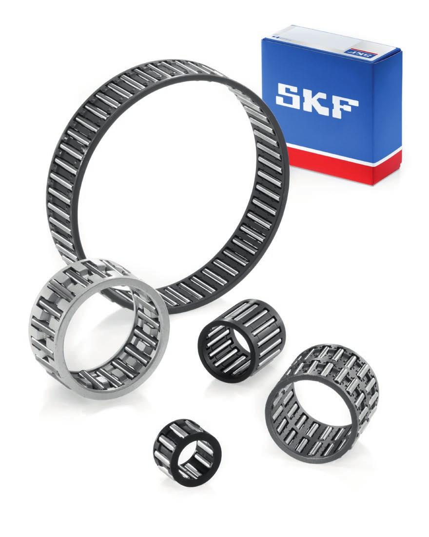
19 Bearing types 1 Needle roller bearings Needle roller bearings are bearings with cylindrical rollers that are small in diameter. In spite of their low cross section, needle roller bearings have a high load carrying capacity and are therefore extremely suitable for bearing arrangements where radial space is limited. SKF supplies needle roller bearings in different designs and in a wide range of sizes, which are appropriate for different applications. In addition to customized designs, they comprise the following types and components: needle roller and cage assemblies drawn cup needle roller bearings universal joint bearings needle roller bearings with machined rings alignment needle roller bearings needle roller thrust bearings bearing washers combined needle roller bearings needle roller bearing inner rings needle rollers radial shaft seals with low cross sectional height Basic information about the different needle roller bearing types, washers, and seals is provided in the following overview. 17
20 Bearing types Needle roller and cage assemblies See chapter 2 starting on page 57 Bearing design Needle roller and cage assemblies Single row Designation series Inside diameter range K.. TN F w = 3 45 mm K F w = mm Characteristics Polyamide 66 cage Steel cage Double row K.. ZWTN F w = 32 mm K.. ZW F w = mm Polyamide 66 cage Steel cage Drawn cup needle roller bearings See chapter 3 starting on page 75 Bearing design Drawn cup needle roller bearings With open ends, HK series, not sealed Designation series Inside diameter range HK.. TN F w = 3 mm HK F w = 4 60 mm Characteristics Polyamide 66 cage Steel cage, sizedependent single or double row ( product tables) With open ends, HK series, sealed on one side HK.. RS F w = 8 50 mm Steel cage, factory greased 18
21 Bearing design Drawn cup needle roller bearings With open ends, HK series, sealed on both sides Designation series Inside diameter range Characteristics 1 HK...2RS F w = 8 50 mm Steel cage, factory greased With a closed end, BK series, not sealed BK.. TN F w = 3 mm Polyamide 66 cage BK F w = 4 45 mm Steel cage, sizedependent single or double row ( product tables) With a closed end, BK series, sealed BK.. RS F w = mm Steel cage, factory greased With open ends, HN series, full complement, not sealed HN F w = mm Factory greased to secure the rollers 19
22 Bearing types Universal joint bearings Not covered in this catalogue. For additional information, refer to the SKF Interactive Engineering Catalogue. Bearing design Universal joint bearings Designation series Characteristics BNKB Specific cold forged cup needle roller bearings for universal joints of commercial vehicle propeller shafts Needle roller bearings with machined rings See chapter 4 starting on page 97 Bearing design Needle roller bearings with machined rings With flanges, without an inner ring, not sealed Designation series Inside diameter range NK.. TN F w = 5 60 mm NK F w = mm NKS F w = mm RNA 49 F w = mm RNA 69 F w = mm RNA 48 F w = mm Characteristics Integral flanges, annular groove and one or more lubrication holes (size dependent) If F w 10 mm: with integral closure rings, without lubrication hole or annular groove RNA 69 series bearings with an outside diameter D 52 mm are designed as double row bearings With flanges, without an inner ring, sealed on one side RNA 49.. RS F w = mm Integral flanges, annular groove and one or more lubrication holes (size dependent), factory greased 20
23 Bearing design Needle roller bearings with machined rings With flanges, without an inner ring, sealed on both sides Designation series Inside/bore diameter range Characteristics 1 RNA RS F w = mm Integral flanges, annular groove and one or more lubrication holes (size dependent), factory greased With flanges, with an inner ring, not sealed NKI.. TN d = 5 55 mm NKI d = mm NKIS d = mm Integral flanges, annular groove and one ore more lubrication holes (size dependent) If d 7 mm: with integral closure rings, without lubrication hole or annular groove NA 49 d = mm NA 69 d = mm NA 48 d = mm NA 69 series bearings with an outside diameter D 52 mm are designed as double row bearings With flanges, with an inner ring, sealed on one side NA 49.. RS d = mm Integral flanges, annular groove and one or more lubrication holes (size dependent), factory greased With flanges, with an inner ring, sealed on both sides NA RS d = mm Integral flanges, annular groove and one or more lubrication holes (size dependent), factory greased 21
24 Bearing types Bearing design Needle roller bearings with machined rings Without flanges, without an inner ring, not sealed Designation series Inside/bore diameter range RNAO.. TN F w = 5 12 mm RNAO F w = mm Characteristics Available as single or double row bearings ( product tables) Double row bearings have an annular groove and a lubrication hole Without flanges, with an inner ring, not sealed NAO.. TN d = 6 9 mm NAO d = mm Available as single or double row bearings ( product table) Double row bearings have an annular groove and a lubrication hole Some bearings have one lubrication hole in the inner ring ( product table) Alignment needle roller bearings See chapter 5 starting on page 141 Bearing design Alignment needle roller bearings Without an inner ring Designation series Inside/bore diameter range RPNA F w = mm Characteristics Can compensate static misalignment up to 3 between the shaft and housing Steel cage, not sealed, no lubrication holes With an inner ring PNA d = mm Can compensate static misalignment up to 3 between the shaft and housing Steel cage, not sealed, no lubrication holes 22
25 Needle roller thrust bearings See chapter 6 starting on page 151 Bearing design Needle roller thrust bearings Designation series Bore diameter range Characteristics 1 Needle roller and cage thrust assemblies AXK.. TN d = 4 8 mm AXK d = mm Appropriate washers: LS, AS, GS 811 and WS 811 series Needle roller thrust bearings with a centring spigot AXW d = mm Can be combined with radial needle roller bearings to accommodate combined radial and axial loads Bearing washers See chapter 6 on page 154 Bearing design Bearing washers Designation series Bore diameter range Characteristics Raceway washers, LS series LS d = mm Ground raceway, turned bore and outside diameter, can be combined with AXK and AXW series Thrust washers, AS series AS d = mm Made of spring steel, 1 mm thick, hardened and polished, can be combined with AXK and AXW series, both sides can be used as raceways 23
26 Bearing types Bearing design Bearing washers Shaft washers, WS 811 series Designation series Bore/outside diameter range WS 811 d = mm Characteristics Precision machined raceway, ground bore, can be combined with AXK and AXW series, for bore diameters up to 160 mm Housing washers, GS 811 series GS 811 D = mm Precision machined raceway, ground outside diameter, can be combined with AXK series, for outside diameters up to 200 mm Combined needle roller bearings See chapter 7 starting on page 169 Bearing design Combined needle roller bearings Needle roller / angular contact ball bearings, NKIA series Designation series Bore diameter range NKIA d = mm Characteristics Can accommodate axial loads in one direction Needle roller / angular contact ball bearings, NKIB series NKIB d = mm Can accommodate axial loads in both directions 24
27 Bearing design Combined needle roller bearings 8 (800) (бесплатно) Designation series Inside diameter range Characteristics NX.. (Z)TN Fw = 7 mm Full complement thrust ball bearing, steel cover with or without lubrication holes NX.. Z series: factory greased thrust bearing, steel cover without lubrication hole 1 Needle roller / thrust ball bearings, NX series NX.. (Z) Fw = mm NX series NX.. Z series Needle roller / thrust ball bearings, NKX series NKX.. (Z)TN Fw = 10 mm NKX.. (Z) Fw = mm NKX series Thrust ball bearing with a cage, with or without steel cover NKX.. Z series: factory greased thrust bearing, steel cover without lubrication hole NKX.. Z series Needle roller / cylindrical roller thrust bearings, NKXR series NKXR series sale@technobearing.ru NKXR Fw = mm Separable bearing design NKXR.. Z Fw = mm Thrust bearing with a steel cover and initial grease fill, non-separable bearing design NKXR.. Z series (800) (бесплатно)
28 Bearing types Needle roller bearing inner rings See chapter 8 starting on page 195 Bearing design Needle roller bearing inner rings Designation series Bore diameter range Characteristics IR d = mm IR.. IS1 d = 6 50 mm Made of carbon chromium bearing steel, hardened, precision machined raceway with a lead-in chamfer on both sides, with or without lubrication hole(s) IR series IR.. IS1 series LR d = 7 50 mm Made of carbon chromium bearing steel, hardened, ground bore and raceway, turned side faces LR series Radial shaft seals with a low cross sectional height See chapter 8 on page 208 Bearing design Radial shaft seals with a low cross sectional height Designation series Bore diameter range Characteristics G.. S d 1 = 4 7 mm G d 1 = 8 70 mm Single lip design, made of acrylonitrile-butadiene rubber Rubber material metal cased Sheet steel reinforced G.. S series G series SD d 1 = 8 50 mm Double lip design, lips are made of polyurethane elastomer, polyamide reinforcement ring SD design 26
29 Track runner bearings SKF track runner bearings are rolling bearings with a very thick-walled outer ring that can accommodate heavy loads as well as shock loads. The designs of track runner bearings are based on ball bearings, needle roller bearings as well as cylindrical roller bearings. SKF supplies track runner bearings in many different designs and for a wide variety of operating conditions and applications. They are ready-to-mount pre-greased units and are intended for all types of cam drives, tracks, conveyor systems, etc. The rails used for SKF linear guides can serve as tracks for the bearings. Basics of the SKF track runner bearing assortment are listed below and comprises the following types: 1 cam rollers support rollers cam followers Cam rollers Not covered in this catalogue. For additional information, refer to the SKF Interactive Engineering Catalogue. Bearing design Cam rollers Single row Designation series Outside diameter range R D = mm Characteristics Sealed, crowned running surface Double row C-2Z D = mm C-2Z D = mm Sealed Crowned running surface Cylindrical running surface C-2Z series C-2Z series 27
30 Bearing types Support rollers See chapter 9 starting on page 215 Bearing design Support rollers Without flange rings, (R)STO and (R)NA RS designs Designation series Outside diameter range STO.. TN D = mm STO D = mm RSTO.. TN D = mm Characteristics Crowned running surface STO design RSTO design RSTO D = mm NA 22 2RS D = mm RNA 22 2RS D = mm NA 22 2RS design RNA 22 2RS design With flange rings, NATR and NATV designs NATR NATV D = mm Crowned running surface NATR design NATV design NATR.. PPA NATV.. PPA D = mm Improved crowned running surface NATR.. PPA series NATV.. PPA series 28
31 Bearing design Support rollers With flange rings, NUTR.. A design Designation series Outside diameter range Characteristics 1 NUTR.. A D = mm Can accommodate axial forces and heavy shock loads, improved crowned running surface With flange rings, PWTR...2RS design PWTR...2RS D = mm Improved crowned running surface With flange rings, NNTR...2ZL design NNTR...2ZL D = mm Size-dependent crowned running surface 29
32 Bearing types Cam followers See chapter 9 on page 238 Bearing design Cam followers KR design KR.. B series Designation series Outside diameter range KR.. B D = mm KR.. (PPSKA) D = mm KR.. PPA KRV.. PPA KRE.. PPA D = mm Characteristics Crowned outer ring running surface as standard, designation suffixes PPSKA and PPA with an improved crowned profile, with or without axial sliding rings, cage-guided or full complement of needle rollers, concentric or eccentric seat, sizedependent characteristics regarding relubrication and holding during mounting KR.. PPSKA series KRV.. PPA series KRE.. PPA series 30
33 Bearing design Cam followers NUKR design Designation series Outside diameter range Characteristics 1 NUKR.. A NUKRE.. A D = mm Improved crowned profile of the outer ring running surface, concentric seat or eccentric collar on the stud NUKR.. A design NUKRE.. A design PWKR design PWKR...2RS PWKRE...2RS D = mm Improved crowned profile of the outer ring running surface, concentric seat or eccentric collar on the stud PWKR...2RS design PWKRE...2RS design 31
34 Bearing life and loads Bearing life The bearing size to be used can be selected on the basis of its load ratings in relation to the applied loads and the requirements regarding bearing life and reliability. A simple way to calculate bearing life is the classic ISO formula for basic rating life. However, SKF recommends using the SKF rating life, which makes predicting bearing life more reliable. The values of the basic dynamic load rating C and the basic static load rating C 0 are listed in the product tables. For additional information about the calculation methods and the equations, refer to the SKF General Catalogue. Calculations can also be performed easily online using the SKF Interactive Engineering Catalogue, available online at The general information about bearing life calculations and basic load ratings provided in the SKF General Catalogue and in the SKF Interactive Engineering Catalogue are also valid for needle roller bearings. Equivalent bearing loads Needle roller bearings can accommodate either radial loads (radial bearings) or axial loads (thrust bearings). Therefore, the equivalent bearing load P is equal to the calculated bearing load F and can be inserted directly into the life equations. Combined needle roller bearings The equation P = F is also valid for the radial and thrust bearing of combined needle roller bearings. It is necessary to calculate the life of the radial needle roller bearing and the thrust bearing separately. For needle roller / angular contact ball bearings, the axial component of the load F a must not exceed 25% of the radial component of the load F r. The values of the basic load ratings C for the radial and axial bearings are listed separately in the product tables. Static bearing loads The basic static load rating C 0 is used in calculations when the bearings are to: rotate at very slow speeds (n < 10 r/min) perform very slow oscillating movements be stationary under load for extended periods be under shock or heavy peak loads, whether it is rotating (dynamically stressed) or at rest If one of these conditions exists, refer to the SKF General Catalogue (section Selection of bearing size). Requisite minimum load The correlation between load and service life is less important when bearings are subjected to very light loads, because the failure mode is typic ally something other than fatigue. To achieve satisfactory operation, needle roller and track runner bearings must always be subjected to a requisite minimum load. Applying a requisite minimum load is especially important for bearings that operate at high speeds or are subjected to high acceler ations or rapid changes in the direction of load. Under these conditions, not applying the correct minimum load can 32
35 result in damaging sliding movement between the rollers and raceways caused by the inertia forces of the needle rollers and cage and friction in the lubricant. The requisite minimum radial and axial loads to be applied can be estimated for: radial needle roller bearings using F rm = 0,02 C needle roller thrust bearings using When starting up at low temperatures or when the lubricant is highly viscous, an even greater minimum load may be required. However, the weight of the components supported by the bearing, together with the external forces, generally exceeds the requisite minimum load. If this is not the case, the bearing must be subjected to an additional radial and/or axial load. 1 F am = 0,0005 C 0 track runner bearings using F rm = 0,0167 C 0 The requisite minimum axial load for the thrust part of combined bearings can be obtained for: angular contact ball bearings using C 0 q n d m w 2 F am = 0, < z cylindrical roller thrust bearings using q n w 2 F am = 0,0005 C 0 + A < z thrust ball bearings using q n w 2 F am = A < z where F rm = minimum radial load [kn] F am = minimum axial load [kn] C = basic dynamic load rating ( product tables) [kn] C 0 = basic static load rating ( product tables) [kn] d m = mean bearing diameter = 0,5 (d + D) [mm] n A = rotational speed [r/min] = minimum load factor ( product tables) 33
36 Friction Friction in a bearing can be described as the resistance to rotation. The friction dictates the amount of heat generated within a bearing and consequently determines the bearing operating temperature. The amount of friction within a bearing depends on the load and several other factors including bearing type, size, operating speed, and the properties and quantity of the lubricant. Friction in a bearing is produced in the contact areas. These are the areas where the rolling elem ents make contact with the raceways, cage(s), guiding surfaces and lubricant. If the bearing is sealed, the contact area also includes the area where the sealing lip makes contact with its counterface. Coefficient of friction µ for bearings without seals, with a cage Bearing type Coefficient Radial needle roller bearings 0,0022 Needle roller thrust bearings 0,0050 Thrust part of combined bearings Angular contact ball bearings 0,0020 Thrust ball bearings 0,0013 Cylindrical roller thrust bearings 0,0050 Table 1 Estimating the frictional moment The frictional moment can be calculated with sufficient accuracy under the following conditions: bearing load P 0,1 C good lubrication normal operating conditions When using a coefficient of friction, the equations to be used are the following: for radial needle roller bearings M = 0,5 μ P F w and for other bearing types where M = frictional moment [Nmm] µ = coefficient of friction ( table 1) P = equivalent dynamic bearing load [N] F w = diameter under rollers [mm] For needle roller bearings with an inner ring, the inner ring raceway diameter F is to be used. d = bearing bore diameter [mm] For additional information about calculating the frictional moment of needle roller bearings, refer to the SKF General Catalogue. Calculations can be easily performed online using the SKF Interactive Engineering Catalogue, available online at For information about calculating the frictional moment of track runner bearings, contact the SKF application engineering service. M = 0,5 µ P d 34
37 Speeds 1 In the product tables, two speeds are typically listed: reference speed and limiting speed. The reference speed represents the speed, under specific operating conditions, at which there is equilibrium between the heat that is generated by the bearing and the heat that is dissipated from the bearing via the shaft, housing and lubricant. Limiting speed is determined by criteria that include the form stability or strength of the cage, lubrication of cage guiding surfaces, centri fugal and gyratory forces acting on the rolling elements, precision and other speedlimiting factors such as seals and lubricant for sealed bearings. Which of these two speed values to consider depends on the needs of the application. In certain applications, such as very low speeds or oscillating movements, the speed limits are superseded in importance by other considerations. For certain bearings, where the speed limit is not determined by heat from the rolling elements/raceway contacts, only limiting speeds are listed in the product tables. These include, for example, bearings with contact seals and all track runner bearings. For additional information about speeds and calculations, refer to the SKF General Catalogue (section Speeds and vibration). 35
38 Bearing data general SKF needle roller bearings are manufactured to several specifications. These specifications, concerning tolerances and internal clearance, are described in the following sections. Information about each bearing type is provided in the introductory text of the individual product chapters. Tolerances Unless otherwise stated, the needle roller bearings listed in this catalogue are manufactured to dimensional, form and running accuracy of needle roller bearings in accordance with the following international standards: ISO 199:2005: Rolling bearings Thrust bearings Tolerances ISO 492:2002: Rolling bearings Radial bearings Tolerances Information about the bearing types and the relevant tolerance classes are provided in the introductory text of the individual product chapters as well as tolerances for the inside diameter F w of the roller set. Actual tolerance values are listed in tables 2 to 5 on pages 38 to 41. The tolerance symbols used there are listed together with their definitions in table 1. 36
39 Table 1 Tolerance symbols Symbol Definition Bore diameter 1 d Nominal bore diameter d mp Mean bore diameter, arithmetical mean of the largest and smallest single bore diameters in one plane Δ dmp Deviation of the mean bore diameter from the nominal (Δ dmp = d mp d) V dp Bore diameter variation; difference between the largest and smallest single bore diameters in one plane V dmp Mean bore diameter variation; difference between the largest and smallest mean bore diameter Outside diameter D Nominal outside diameter D mp Mean outside diameter; arithmetical mean of the largest and smallest single outside diameters in one plane Δ Dmp Deviation of the mean outside diameter from the nominal (Δ Dmp = D mp D) V Dp Outside diameter variation; difference between the largest and smallest single outside diameters in one plane V Dmp Mean outside diameter variation; difference between the largest and smallest mean outside diameters of one ring or washer Width or height B s, C s Single width of the inner ring and outer ring, respectively Δ Bs, Δ Cs Deviation of the single inner ring width or single outer ring width from the nominal (Δ Bs = B s B; Δ Cs = C s C) V Bs, V Cs Ring width variation; difference between the largest and smallest single widths of the inner ring and of the outer ring, respectively T S Single height (H) of a single direction thrust bearing Δ Ts Deviation of the single height of a thrust bearing from the nominal (Δ Ts = T S T) Running accuracy K ia, K ea S d S D S i, S e Radial runout of the inner ring and outer ring, respectively, of an assembled bearing Side face runout with reference to the bore (of an inner ring) Outside inclination variation; variation in inclination of an outside cylindrical surface to an outer ring side face Thickness variation, measured from the middle of the raceway to the back (seat) face of the shaft washer and of the housing washer, respectively (axial runout) 37
40 Bearing data general Table 2 Normal tolerances for radial needle roller bearings and track runner bearings Inner ring d 1) Δ dmp V dp V dmp Δ Bs V Bs K ia over incl. high low max max high low max max mm μm μm µm µm μm µm 2, ) For cam followers the stud shank diameter d can be used as the bore diameter reference. Outer ring D Δ Dmp V Dp V Dmp Δ Cs, V Cs K ea over incl. high low max max max mm μm μm µm μm Values are identical to those for 20 inner ring of same bearing (Δ Bs, V Bs )
41 Table 3 Class P6 tolerances for radial bearings Inner ring 1 d Δ dmp V dp V dmp Δ Bs V Bs K ia over incl. high low max max high low max max mm μm μm µm µm μm µm 2, Outer ring D Δ Dmp V Dp V Dmp Δ Cs, V Cs K ea over incl. high low max max max mm μm μm µm μm Values are identical to those for 10 inner ring of same bearing (Δ Bs, V Bs )
42 Bearing data general Table 4 Class P5 tolerances for radial bearings Inner ring d Δ dmp V dp V dmp Δ Bs V Bs K ia S d over incl. high low max max high low max max max mm μm μm µm µm μm µm µm 2, Outer ring D Δ Dmp V Dp V Dmp Δ Cs V Cs K ea S D over incl. high low max max max max max mm μm μm µm μm µm µm Values are identical to those for inner ring of same bearing (Δ Bs, V Bs )
43 Chamfer dimension limits r 2max r 2min r 1min r 1max Table 6 Limits for chamfer dimensions Minimum values for the chamfer dimensions are listed in the product tables. To prevent the improper dimensioning of fillets on associated components for needle roller bearings and to facilitate the calculation of snap ring location arrangements, the maximum chamfer limits for the relevant minimum value of chamfer dimensions are listed in table 6. These limits are in accordance with ISO 582:1995. The symbols used are explained below: d nominal bearing bore diameter r 1 maximum value in the radial direction r 2 maximum value in the axial direction r s min general symbol for the minimum value of chamfer dimensions 1 Table 5 Normal tolerance class for washers and thrust bearings Minimum Nominal Maximum values value bearing bore Radial bearings Thrust diameter bearings r s min d r 1 r 2 r 1,2 over incl. max max max mm mm mm 0,1 0,2 0,4 0,2 0,15 0,3 0,6 0,3 0,2 0,5 0,8 0,5 0,3 40 0,6 1 0,8 40 0,8 1 0,8 0, ,5 40 1,3 2 1, ,5 3 2,2 50 1,9 3 2,2 1, ,5 2, ,5 4 2,7 1, ,3 4 3, , , , , , ,5 4, ,5 7 4,5 Shaft washer, WS d Δ dmp V dp S 1) i Δ 1) Ts over incl. high low max max high low mm μm μm µm µm Housing washer, GS d Δ dmp V Dp S e over incl. high low max mm μm μm µm ) Also valid where raceway washers in the LS series are used 41
44 Bearing data general Internal clearance Bearing internal clearance is defined as the total distance through which one bearing ring can be moved relative to the other in the radial direction (radial internal clearance) or in the axial direction (axial internal clearance). It is necessary to distinguish between the internal clearance in a bearing before mounting and the internal clearance in a mounted bearing that has reached its operating temperature (operational clearance). The initial internal clearance (before mounting) is greater than the operational clearance because the degree of the interference fits and the effects of thermal expansion of the bearing rings and associated components will expand or compress the rings. Bearing internal clearance referred to as Normal has been selected so that a suitable operational clearance will be obtained when the bearing is mounted with the recommended fits and operating under normal conditions. In applications where conditions are not normal, e.g. where interference fits are used for both bearing rings, unusual temperatures prevail, or bearings with greater or smaller internal clearance than Normal are required, SKF recommends checking residual clearance in the bearing after it has been mounted. Unless otherwise stated, SKF needle roller bearings with an inner ring have Normal radial internal clearance. Bearings having an internal clearance other than Normal are identified by the designation suffix C2, C3 or C4. The clearance values ( table 7) are in accordance with ISO :2009 and are valid for unmounted bearings under zero measuring load. Table 7 Radial internal clearance for needle roller bearings and track runner bearings Bore diameter Radial internal clearance d 1) C2 Normal C3 C4 over incl. min max min max min max min max mm μm ) For cam followers, the stud shank diameter d can be used as the bore diameter reference. 42
45 Cages Bearing cages can influence the suitability of a rolling bearing for a particular application. Their main purposes are: to separate the rolling elements and keep them spaced evenly for uniform load distribution to reduce noise levels to guide the rolling elements in the unloaded zone to improve rolling conditions and prevent damaging sliding movements to retain the rolling elements when mounting separable bearings Cages are stressed by friction, inertia forces and heat. Depending on the material, cages can also be affected by certain lubricants, lubricant additives, organic solvents, coolants, or by-products of these substances as they age. Therefore, cage design and material are of paramount importance for the performance and the operational reliability of the bearing. For larger bearings, the standard cage may be different than the one used in smaller bearings even though they are in the same design or series. In the introductory text of each product chapter, information is provided about standard cages. Seals The seals integrated in a needle roller bearing can have a considerable impact on the performance and reliability of the bearing. Their primary purpose is to exclude solid contaminants and moisture and retain the lubricant in the bearing. The seal materials must withstand oxidation and offer excellent thermal or chemical resistance. Integral seals are generally contact seals or sliding rings. Depending on the internal geometry and design of the bearing, the arrangement of the bearing and associated components can form non-contact seals and act as efficient labyrinth or gap-type seals. Additional information about seals is available in the introductory text of each product chapter, if seals are available. In addition to integral bearing seals, SKF also supplies an assortment of radial shaft seals that can be used as external seals. Appropriate seals are listed in the product tables, if available. For additional information, refer to the section Radial shaft seals with a low cross sectional height, starting on page 208. Materials The material used to make a bearing component determines, to a large extent, the performance and reliability of that bearing. For the bearing rings and rolling elements, typical considerations include hardness for load carrying capacity, fatigue resistance under rolling contact conditions, under clean or contaminated lubrication conditions, and the dimensional stability of the bearing components. For additional information about seal materials, refer to the SKF General Catalogue. The general information about materials also applies to needle roller bearings. Materials for bearing rings and rolling elements The standard steel used to produce machined rings and rolling elements of SKF needle roller bearings is a carbon chromium steel for through-hardening, containing approximately 1% carbon and 1,5% chromium, in accordance with ISO 683:17:1999. Unless otherwise stated in the product chapters, bearing washers are also made of this carbon chromium bearing steel. The thin-walled deep drawn outer rings of drawn cup needle roller bearings and the drawn sheet steel sleeve of alignment needle roller bearings are exceptions. They are made of mild steel in accordance with EN 10139:1997. The majority of outer rings of track runner bearings are made of bearing steels for casehardening because of their ability to withstand heavy shock loads. Materials that can be used are chromium-nickel and manganesechromium alloyed steel in accordance with ISO :1999. Standard needle roller bearings and track runner bearings made of carbon chromium steel or steel for case hardening are heat stabilized up to 120 C unless otherwise stated in the in tro duc tory text of the product chapter. Bearings used in applications where temperatures exceed 120 C must be subjected to a special heat stabilization process to provide adequate dimensional stability. 1 43
46 Bearing data general Cage materials Polyamide 66 Polyamide 66, with glass fibre reinforcement, is used for cages in many needle roller bearings and thrust bearings. Polyamide 66 is characterized by a favourable combination of strength and elasticity. Due to its excellent sliding properties on lubricated steel surfaces and the superior finish of the contact surfaces, polyamide 66 cages promote low friction, low heat generation and low wear. Polyamide 66 can be used for operating temperatures ranging from 40 to +120 C, provided it does not come in contact with aggressive lubricants. Aggressive lubricants (e.g. oils with EP additives or some synthetic oils) promote ageing effects that can be compensated for by reducing the normal operating temperature. At temperatures below 40 C, polyamide loses its elasticity, which can result in cage failures. For additional information about the cage material, particularly the relationship between the operating temperatures and the cage ageing life, refer to the SKF General Catalogue. Steel cages Steel cages can be used at operating temperatures up to 300 C. They are not affected either by mineral or synthetic oil-based lubricants or by the organic solvents used to clean a bearing. They are designed as window-type cage. Sheet steel cages are pressed from continuously hot-rolled low carbon steel. These lightweight cages have relatively high strength and can be surface treated to further reduce friction and wear. Machined steel cages are made of nonalloyed structural steel. To improve sliding and wear-resistance, some machined steel cages are surface treated. Seal materials Acrylonitrile-butadiene rubber (NBR) Acrylonitrile-butadiene rubber (NBR) is the universal seal material. This copolymer, produced from acrylonitrile and butadiene, shows good resistance to the following media: most mineral oils and greases with a mineral oil base normal fuels: petrol, diesel and light heating oils animal and vegetable oils and fats hot water NBR also tolerates short-term dry running of the sealing lip. The permissible operating temperature range is 40 to +100 C. For brief periods, temperatures of up to 120 C can be tolerated. At higher temperatures, the material hardens. Polyurethane Polyurethane (AU) is a wear-resistant organic ma ter ial with good elastic prop erties. It is resistant to mineral oil based greases and lubricating oils, even those containing small quantities of EP (Extreme Pressure) additives. The permissible operating temperature range is 30 to +100 C. Fluoro rubber Fluoro rubbers (FKM) are characterized by their high thermal and chemical resistance. Their resistance to ageing and ozone is very good and their gas permeability is very slight. They have exceptionally good wear characteristics even under harsh environmental conditions and can withstand operating temperatures up to 200 C. Seals made from this material can tolerate dry running of the lip for short periods. Fluoro rubbers are also resistant to oils and hydraulic fluids, fuels and lubricants, mineral acids and aliphatic, as well as aromatic hydrocarbons, which would cause seals made from other materials to fail. In the presence of esters, ethers, ketones, certain amines and hot anhydrous hydrofluorides, fluoro rubbers should not be used. Note At temperatures above 300 C, fluoro rubber gives off dangerous fumes. As handling seals made of fluoro rubber constitutes a potential safety risk, the safety precautions mentioned hereafter must always be followed. 44
47 WARNING! Safety precautions for fluoro rubber Fluoro rubber is very stable under normal operating conditions up to 200 C. At temperatures above 200 C, the material hardens and loses its effectiveness. At temperatures above 300 C, which is usually the result of a fire or the flame of a cutting torch, fluoro rubber seals will give off hazardous fumes which can be harmful to the eyes and, if inhaled, to the respiratory system. Once fluoro rubber has been heated to 300 C or above, it is dangerous to handle, even after it has cooled. Therefore, the following safety precautions should be observed when handling such material: 1 Always wear protective goggles, gloves and appropriate breathing apparatus. Place the remains of the seals in an airtight plastic container marked with a symbol for material will etch. Follow the safety precautions in the appropriate material safety data sheet (MSDS). Anyone who contacts these seals or their remains should wash their hands with soap and plenty of water and flush eyes with plenty of water and consult a doctor immediately. If the fumes have been inhaled, they should consult a doctor immediately. The user is responsible for the correct use of the product during its service life and its proper disposal. 45
48 Bearing data general Supplementary designations The complete designation for needle roller and track runner bearings consists of a basic designation, which identifies bearing type and size, as well as supplementary designations. These designation suffixes identify design features that differ from the standard design. Where several supplementary designations are used to identify a particular bearing, they are always written in a specific order. The supplementary designations listed below are not exhaustive, but include those most commonly used. Suffix A AS.. ASR.. B BF C2 C3 CN C4 D DS Description NUTR design support rollers and NUKR design cam followers with an improved crowned profile of the outer ring running surface Lubrication hole(s) in the outer ring, a figure following indicates the number of holes Annular groove and lubrication hole(s) in the outer ring, a figure following indicates the number of holes KR design cam followers with a crowned profile of the outer ring running surface and a recessed hexagon on both ends of the stud Needle roller with flat ends Bearing internal clearance smaller than Normal Bearing internal clearance greater than Normal Bearing internal clearance Normal, only used together with an additional letter (H, L, M, P) that identifies a reduced or displaced clearance range Bearing internal clearance greater than C3 Deviating or modified internal design with the same boundary dimensions. Generally dropped after a certain changeover period, but may have the significance to bound to the particular bearing design/series Example: K D Needle roller and cage assembly with a double split cage Single split needle roller and cage assembly EGS Inner ring with a non-directionally ground raceway G2 Needle roller in accordance with ISO 3096:1996 Grade 2 H.. Needle roller bearing without an inner ring, with reduced inside diameter (under rollers) tolerance, followed by tolerance limits in μm, e.g. H IS.. Needle roller bearing with one or more lubricating holes in the inner ring, a figure following indicates the number of holes ISR.. Needle roller bearing with an annular groove and one or more lubricating holes in the inner ring, a figure following indicates the number of holes M../M.. Diameter tolerance of needle rollers, e.g. M2/M4 indicates diameter tolerance 2 to 4 µm N/M.. Diameter tolerance of needle rollers, e.g. N/M2 indicates diameter tolerance 0 to 2 µm P5 Dimensional and running accuracies to ISO tolerance class 5 P6 Dimensional and running accuracies to ISO tolerance class 6 P6CNR P6 + CNR P62 P6 + C2 P63 PPA P6 + C3 1. NATR or NATV design support rollers with a polyamide 66 axial sliding and sealing ring on both sides. Improved crowned profile of the outer ring running surface. 2. KR design cam followers have the same features as listed above. Sizes 16 and 19 have one slot in the head of the stud as standard. Size 22 and larger have a recessed hexagon on both ends. PPSKA KR design cam followers, sizes 16 and 19, with a polyamide 66 axial sliding and sealing ring on both sides, improved crowned profile of the outer ring running surface and a hexagon recessed into the head of the stud. These cannot be relubricated. PPXA RS Cam followers with PPA features except for the outer ring running surface, which has a cylindrical profile Contact seal of acrylonitrile-butadiene rubber (NRB) with or without sheet steel reinforcement on one side of the bearing 46
49 .2RS RS contact seal on both sides of the bearing..s Matched bearings for an equal distribution of the radial load. The figure preceding indicates the number of bearings, e.g. NK 50/25 TN/2S S Radial shaft seals with low cross sectional height, rubber material is metal cased, e.g. G S 2S Two matched bearings for an equal distribution of radial load (refer to S, the figure preceding the S indicates the number of bearings) S0 Bearing rings or washers dimensionally stabilized for use at operating tempera tures up to 150 C S1 Bearing rings or washers dimensionally stabilized for use at operating tempera tures up to 200 C S2 Bearing rings or washers dimensionally stabilized for use at operating tempera tures up to 250 C S3 Bearing rings or washers dimensionally stabilized for use at operating tempera tures up to 300 C SM.. Special grease, two figures following identify the grease /SORT.. Tolerance grade of needle rollers of a needle roller and cage assembly, the figures following give the actual limits in μm, e.g. /SORT-2-4 TN Injection moulded cage of glass fibre reinforced polyamide 66 VGS Inner ring with a pre-ground raceway and a machining allowance VG052 Single split cage of polyethersulfone (PES) X Track runner bearings with a cylindrical (flat) profile of the outer ring running surface XA NUKR.. A and NUKRE.. A design cam followers with a cylindrical (flat) profile of the outer ring running surface Z Combined needle roller bearings, axial bearing with a cover over the outside diameter without lubrication holes. Filled at the factory with a high-quality lithium base NLGI 2 grease. ZW Double row needle roller and cage assembly.2zl Support rollers with a lamellar seal on both sides 1 47
50 Application of bearings Application of bearings The bearing arrangement of a rotating machine component such as a shaft generally requires locating and a non-locating bearing arrangement to support and locate the component radially and axially relative to the housing. As radial needle roller bearings can accommodate axial displacement within the bearing, they generally are used as non-locating bearings. Needle roller thrust bearings can only accommodate axial loads acting in one direction. A double direction needle roller thrust bearing can be created by combining two needle roller and cage thrust assemblies and bearing washers with an intermediate washer. Radial loads must be accommodated by a combined needle roller bearing or a separate radial bearing. Combined needle roller bearings can accommodate radial loads and axial loads in one direction only. Therefore, a second combined needle roller bearing is required to be able to take axial loads in the opposite direction (except NKIB series needle roller bearings that can accommodate axial loads in both directions). For additional information about bearing arrangements, refer to the SKF General Catalogue. The application information for bearings provided in the SKF General Catalogue is also valid for needle roller bearings. If necessary, the introductory text of each product chapter provides information about axial guidance axial and radial location recommended fits for shafts and housings Design of associated components Form and running accuracy Good running accuracy, required speeds and low operating temperatures can only be achieved if the associated components and other mating parts are manufactured with equal precision as the needle roller bearings. Deviations from geometric form of associated seats and abutments must be kept to a minimum. The parts should be machined according to the following recommendations. Table 1 Limits for ISO tolerance grades Nominal Tolerance grades dimension IT2 IT3 IT4 IT5 IT6 IT7 over incl. max mm μm 1 3 1, ,5 2, ,5 2, , ,
51 Dimensional tolerances For bearings manufactured to Normal tolerances, the dimensional accuracy of cylindrical seats on the shaft should be at least grade 6 and in the housing at least grade 7. For bearings with higher accuracy, correspondingly better grades should be used. The numerical values of standard IT tolerance grades, in accordance with ISO 286-1:1988, are listed in table 1. 1 Table 2 Accuracy of form and position for bearing seats on shafts and in housings A t 1 t 3 A-B B A t 2 A-B t 4 A-B B d A d B D A D B t 2 A-B t 4 A-B t 1 t 3 A-B Surface Permissible deviation Characteristic Symbol for Bearings of tolerance class 1) characteristic tolerance zone Normal P6 P5 Cylindrical seat Cylindricity t 1 IT5 IT4 IT IT5 IT4 IT3 Total radial runout t Flat abutment Perpendicularity t 2 IT5 IT4 IT3 Total axial runout t 4 IT5 IT4 IT3 1) The basic tolerance classes stated are valid for normal demands on the bearing arrangement. For special demands in respect of running accuracy or even support, the bearing seat should be machined to the basic tolerance classes recommended for the next higher bearing tolerance class. 49
52 Application of bearings Tolerances for cylindrical form The cylindricity tolerances as defined in ISO should be one to two IT grades better than the prescribed dimensional tolerance, depending on requirements. For example, if a bearing shaft seat has been manufactured to m6 tolerance class, then the accuracy of form should be to IT5 or IT4 tolerance grade. The tolerance value for cylindricity, t 1, is obtained for an assumed shaft diam eter of 150 mm from t 1 = IT5/2 = 18/2 = 9 µm. However, the tolerance t 1 is for a radius, hence 2 t 1 applies for the shaft diameter. Guideline values for the cylindrical form tolerance and the total runout tolerance for the different bearing tolerance classes are listed in table 2 on page 49. Tolerances for perpendicularity Abutments for bearing rings should have a rectangularity tolerance as defined in ISO , which is better by at least one IT grade than the diameter tolerance of the associated cylindrical seat. For thrust bearing washer seats, the tolerance for perpendicularity should not exceed IT5 tolerance grade. Guideline values for the tolerance for rectangularity and for the total axial runout are listed in table 2 on page 49. Surface roughness of bearing seats The surface roughness of a bearing seat does not have the same degree of influence on bearing performance as the dimensional, form and running accuracies. However, the accuracy of an interference fit is directly proportional to the smoothness of the mating surface. For bearing arrangements where accuracy is a key operational parameter, guideline values for the mean surface roughness R a are listed in table 3. These recommendations apply to ground seats, which are normally assumed for shaft seats. Raceways on shafts and in housings Raceway hardness and its influence If the load carrying capacity of the bearing or assembly is to be fully exploited, the raceways machined in associated components must be hardened to between 58 and 64 HRC. Raceway surface finish and accuracy The surface roughness should be R a 0,2 μm or R z 1 μm. For less demanding applications, rougher surfaces may be used. The out-of-round and deviation from cylindrical form must not exceed 25 and 50%, respectively, of the actual diameter tolerance of the raceway. The permissible axial runouts of raceways for thrust assemblies are the same as for the shaft and housing washers of thrust bearings, listed in table 5 on page 41. Raceway materials Suitable materials for the raceways include steel for through-hardening, e.g. 100Cr6 in accordance with ISO :1999, steels for casehardening, e.g. 20Cr3 or 17MnCr5 in accordance with ISO :1999) as well as steels for induction-hardening that can be surface hardened. Table 3 Guideline values for surface roughness of bearing seats Diameter Recommended R a value of seat for ground seats d (D) Diameter tolerance to over incl. IT7 IT6 IT5 mm μm 80 1,6 (N7) 0,8 (N6) 0,4 (N5) ,6 (N7) 1,6 (N7) 0,8 (N6) 50
53 The recommended hardening depth for raceways machined in associated components depends on various factors including the dynamic and static load ratios (P/C and P 0 /C 0 respectively) as well as the core hardness of the component. Therefore, it is difficult to make generalizations regarding hardening depth. For example, under conditions of purely static load up to the magnitude of the basic static load rating and with a core hardness of 350 HV, the recommended hardening depth is in the order of 0,1 times the rolling element diameter. For dynamic loads, however, smaller hardening depths are permitted. For additional information, contact the SKF application engineering service. 1 51
54 Lubrication If rolling bearings are to operate reliably they must be adequately lubricated to prevent direct metal-to-metal contact between the rolling elem ents, raceways and cages. The lubricant also inhibits wear and protects the bearing surfaces against corrosion. The choice of a suitable lubricant and method of lubrication for each individual bearing application is therefore important, as is adequate maintenance. Differences in the lubricating properties of seemingly identical lubricants particularly grease produced at different locations can exist. As a result, SKF will not accept responsibility for the performance of any of its lubricants. The user is therefore advised to specify lubricant properties in detail so as to obtain the most suitable lubricant for the application. The SKF traffic light concept Most grease suppliers indicate the specific values for the low and high temperature limits in their product information. The SKF traffic light concept is distinctly different from that. SKF recognizes that the really important temperatures for reliable operation lie within a smaller range. This range depends largely on the type of base oil and thickener used, as well as the additives. The relevant temperatures are given by the SKF traffic light concept. They are schematically illustrated in diagram 1 in the form of a double traffic light. It is clear that grease in the red zones should not be applied at all, as damage may occur. Within the green zone, the grease will function reliably and the grease life can be determined accurately. At temperatures in the amber zone above the high temperature performance limit (HTPL), grease will age and oxidize with increasing rapidity and the by-products of the oxidation will have a detrimental effect on lubrication. An amber zone also exists for low temperatures. Short periods in this zone such as during a cold start are not harmful since the heat caused by friction will bring the bearing temperature into the green zone. For additional information about the SKF traffic light concept, refer to the SKF General Catalogue (section Lubrication). 52
55 Lubricating greases The following explains basics concerning initial grease fills, if available, and gives recommendations for SKF greases that can be used for relubri cation. Certain features, which facilitate efficient lubrication and relubrication of the bearings are provided in the introductory text of the individual product chapters. For additional information about lubrication and calculation of relubrication intervals, refer to the SKF General Catalogue (section Lubrication). The SKF grease selection program Lube Select available online at provides a more detailed selection of appropriate greases. Initial grease fill Sealed needle roller bearings and track runner bearings The following bearings are filled at the factory with the same high-quality grease with good cor rosion inhibiting properties: sealed needle roller bearings thrust part of combined bearings with the designation suffix Z cam followers support rollers SKF recommends SKF LGWA 2 grease, if relubrication is required. The most important technical specifications for grease for initial fill and for relubrication are listed in table 1 on page The SKF traffic light concept general Diagram 1 Do not use Unreliable performance (use only for short periods) Reliable performance, i.e. with predictable grease life Temperature LTL LTPL HTPL HTL LTL Low temperature limit The lowest temperature at which the grease will enable the bearing to be started up without difficulty LTPL Low temperature performance limit Below this limit, the supply of grease to the contact surfaces of rolling elements and raceways may become insufficient HTPL High temperature performance limit Above this limit the grease will age and oxidize in an uncontrolled way, so that grease life cannot be determined accurately HTL High temperature limit When exceeding this limit, the grease loses its structure permanently 53
56 Lubrication Full complement drawn cup needle roller bearings Special grease is used for full complement drawn cup needle roller bearings to secure the rollers during transportation. However, this grease does not provide sufficient long term lubrication. Therefore, relubrication after mounting may be necessary. Depending on the required consistency class, SKF recommends SKF LGEP 2 or SKF LGMW 1 greases for relubrication. Characteristics for the greases are listed in table 2. Table 1 Lubricating greases for sealed needle roller bearings and track runner bearings Initial grease fill LGWA 2 Thickener Lithium complex soap Lithium complex soap Base oil type Mineral Mineral NLGI consistency class 2 2 Temperature range 1) [ C] [ F] Base oil viscosity [mm 2 /s] at 40 C at 100 C 15,5 15 1) Refer to the SKF traffic light concept. Greases for full complement drawn cup needle roller bearings Initial grease fill LGEP 2 LGMW 1 Table 2 Thickener Lithium soap Lithium soap Lithium soap Base oil type Mineral Mineral Mineral NLGI consistency class Temperature range 1) [ C] [ F] Base oil viscosity [mm 2 /s] at 40 C at 100 C 18, ) Refer to the SKF traffic light concept. 54
57 1 55
58
59 Needle roller and cage assemblies 2 Dimensions Tolerances Operational clearance Misalignment Cages Abutment dimensions Supplementary designations Product tables Needle roller and cage assemblies
60 Needle roller and cage assemblies Needle roller and cage assemblies are readyto-mount, self-contained bearing components. They are an excellent choice for applications that require a very rigid bearing arrangement as well as a high load carrying capacity. If the shaft and housing bore can serve as raceways, needle roller and cage assemblies require minimal radial space. Standard needle roller and cage assemblies SKF supplies needle roller and cage assemblies in single row ( fig. 1) and double row ( fig. 2) designs. They are characterized by: a simple and rugged design accurate guidance of the rollers in the cage pockets good running performance journal) ( fig. 5). The assemblies for these applications can provide excellent service in spite of high accelerations, high temperatures, unfavourable load conditions or poor lubrication conditions. SKF also supplies special sizes of needle roller and cage assemblies to special order. Details of these other needle roller and cage assemblies are available on request. Dimensions The dimensions of needle roller and cage assemblies with an inside diameter up to and including 100 mm, where standardized, are in accordance with ISO 3030:1996. Other needle roller and cage assemblies Only part of SKF s comprehensive assortment of needle roller and cage assemblies is listed in the product tables. SKF also supplies other sizes and assemblies with cages that differ from the standard design, such as needle roller and cage assemblies with a split cage ( fig. 3) that can be used where raceways are recessed in the shaft. For connecting rods of internal combustion engines and compressors, SKF supplies special needle roller and cage assemblies for the gudgeon (wrist) pin ( fig. 4) and crank pin (crankshaft Needle roller and cage assembly, single row Fig. 1 Needle roller and cage assembly, double row Fig. 2 K series K.. ZW series 58
61 Fig. 3 Bearing arrangement incorporating split needle roller and cage assemblies 2 Needle roller and cage assembly for gudgeon pin bearing arrangements Fig. 4 Fig. 5 Needle roller and cage assembly for crank pin bearing arrangements 59
62 Needle roller and cage assemblies Tolerances SKF needle roller and cage assemblies contain rollers of one gauge of grade G2 (ISO 3096: 1996 Grade 2). The tolerance of each gauge is 2 μm. The deviation from the nominal dimensions of the needle rollers is printed on the package. SKF needle roller and cage assemblies may comprise, as standard, assemblies of any standard gauge ( table 1). If a specific gauge is required, it must be stated when ordering. Assemblies with rollers of a special gauge ( table 1) are only available by special order on request. The tolerances for the width U are 0,20/ 0,80 mm for all needle roller and cage assemblies. Paired mounting Needle roller and cage assemblies that are mounted immediately adjacent to each other must incorporate rollers of the same gauge. This will enable both assemblies to share the load equally. Operational clearance The radial operational clearance of bearing arrangements incorporating needle roller and cage assemblies is determined by: the gauge of the needle rollers the shaft and housing raceway tolerances the operating temperature Suitable raceway tolerance classes are listed in table 2. If these tolerances are applied when using assemblies with standard gauge rollers ( table 1), under normal conditions the operational clearance will reach a value in the range of C2 to Normal radial internal clearance ( table 7, page 42). If a specific radial internal clearance is required, the various components of the arrangement should be matched following a mounting scheme similar to the one shown in table 3. The mean value of the needle roller gauge should be used to calculate the internal clearance, e.g. 6 μm for the gauge 5 to 7 μm. Needle roller gauges Gauge type Gauge in μm Standard gauges 0/ 2 1/ 3 2/ 4 3/ 5 4/ 6 5/ 7 Special gauges (to order) 6/ 8 7/ 9 8/ 10 9/ 11 Table 1 Table 2 Raceway tolerance classes for needle roller and cage assemblies Shaft Housing/shaft tolerance classes Nominal for operational clearance diameter lower medium higher over incl. side side mm 80 G6/j5 G6/h5 G6/g6 H6/h5 H6/g5 H6/f G6/h5 G6/g5 G6/f6 120 G6/h5 G6/g5 G6/f6 H6/f5 H6/e6 60
63 Misalignment The ends of the needle rollers are relieved slightly to modify the line contact between the raceways and the rollers. This provides favourable load distribution in the needle roller and cage assembly and minimizes damaging edge stresses. It also enables single row needle roller and cage assemblies to accommodate a small amount of misalignment, approximately 1 min of arc between the shaft and housing. The detrimental effects of misalignment increase with increasing bearing width and load. For additional information, contact the SKF application engineering service. 2 Table 3 Mounting scheme example Needle roller and cage assembly: K Housing bore diameter: 22H6 (mm), deviation 0/+13 μm Shaft diameter: 16h5 (mm), deviation 0/ 8 μm Shaft diameter Housing bore diameter Deviation group Deviation groups 0 to to to to +13 Needle Radial Needle Radial Needle Radial Needle Radial roller internal roller internal roller internal roller internal gauge clearance gauge clearance gauge clearance gauge clearance limits limits limits limits μm μm 0 to 3 5/ / to 6 5/ / / / 6 6 to 8 5/ / / / / 8 4/ 6 3/ 5 1/ 3 61
64 Needle roller and cage assemblies Cages SKF needle roller and cage assemblies are fitted, as standard, with a machined steel cage ( fig. 6) or a sheet steel cage ( fig. 7), with the exception of assemblies identified by the designation suffix TN. These have an injection moulded glass fibre reinforced polyamide 66 cage ( fig. 8). Note Needle roller and cage assemblies with a polyamide 66 cage can be operated at temperatures up to 120 C. The lubricants generally used for rolling bearings do not have a detrimental effect on cage properties. Exceptions are a few synthetic oils and greases with a synthetic oil base and lubricants containing a high proportion of EP additives when used at high temperatures. For bearing arrangements that operate at continuously high temperatures or under arduous conditions, SKF recommends using assemblies with a steel cage. For additional information about the tempera ture resistance and the applicability of cages, refer to the section Cage materials, starting on page 44. Machined steel cage Sheet steel cage Fig. 6 Fig. 7 Polyamide 66 cage Fig. 8 62
65 Abutment dimensions Needle roller and cage assemblies should be axially guided. The lateral abutment surfaces should be fine turned and polished. For high speed operation they should be hardened and ground. Interruptions in the surface should be avoided. Snap rings can be used in less demanding applications, otherwise an intermedi ate ring, e.g. a spring steel washer, should be placed between the snap ring and the assembly. Appropriate values for the abutment diameters on the shaft and in the housing are listed in table 4. Abutment dimensions for needle roller and cage assemblies d a U H12 U E w Table 4 2 Supplementary designations The designation suffixes used to identify certain features of SKF needle roller and cage assemblies are explained in the following. U H12 U DS Split needle roller and cage assembly /SORT.. Tolerance grade of needle rollers of a needle roller and cage assembly, the figures following give the actual limits in μm, e.g. /SORT-2-4 TN Injection moulded cage of glass fibre reinforced polyamide 66 VG052 Single split cage of polyethersulfone (PES) ZW Double row needle roller and cage assembly (double row cage) D a F w Needle roller and Shaft Housing cage assembly abutment abutment Inside diameter F w d a D a over incl. mm mm mm 25 E w 0,3 F w +0, E w 0,5 F w +0,5 65 E w 1 F w +1 63
66 Needle roller and cage assemblies F w 3 19 mm U E w F w K Dimensions Basic load ratings Fatigue Speed ratings Mass Designation Appropriate dynamic static load limit Reference Limiting seal 1) speed speed Designation F w E w U C C 0 P u mm kn kn r/min g ,51 1,34 0, ,3 K TN 5 9 1,72 1,63 0, ,4 K TN 6 7 1,42 1,02 0, ,4 K TN ,72 1,32 0, ,5 K TN ,29 1,9 0, ,7 K TN ,29 2 0, ,7 K TN ,92 2,7 0, ,9 K TN ,55 2,36 0, ,8 K TN ,3 3,2 0, ,1 K TN ,69 3,15 0, ,9 K TN G S ,68 1,83 0, ,6 K TN ,81 2,75 0, ,9 K TN ,58 3,75 0, ,0 K TN ,03 3,1 0, ,0 K TN ,8 4,25 0, ,2 K TN ,01 5,85 0, ,7 K TN ,84 4,75 0, ,0 K TN G ,4 5,2 0, ,5 K TN ,72 7,2 0, ,1 K TN ,57 5,7 0, ,6 K TN ,94 8 0, ,3 K TN ,82 9,5 1, ,9 K TN ,61 6,1 0, ,5 K TN G ,83 6,3 0, ,6 K TN G ,65 7,2 0, ,5 K TN ,73 6,2 0, ,9 K TN ,16 8,65 0, ,3 K TN ,65 9,5 1, ,6 K TN G ,13 10,4 1, ,9 K TN , , ,0 K TN G/SD ) For additional information, refer to the section Radial shaft seals with a low cross sectional height, starting on page
67 2.1 Dimensions Basic load ratings Fatigue Speed ratings Mass Designation Appropriate dynamic static load limit Reference Limiting seal 1) speed speed Designation F w E w U C C 0 P u mm kn kn r/min g ,93 8, ,0 K ,92 10,2 1, ,5 K ,13 12,5 1, ,0 K TN ,5 14,6 1, ,0 K ,9 10,6 1, ,5 K G/SD ,65 12,2 1, ,6 K TN ,21 9,3 1, ,0 K ,25 11,2 1, ,0 K ,8 15,6 1, ,5 K ,52 11,6 1, ,0 K ,8 16, K G/SD ,7 24, K G/SD , , ,5 K , , ,5 K , K ,5 1, K G/SD ,2 17,6 2, K G/SD ,6 22,8 2, K G/SD ,5 23,6 2, K G/SD ,81 10,8 1, ,5 K ,1 14,6 1, ,5 K ,7 18,3 2, ,5 K ,09 11,4 1, ,0 K ,8 12,9 1, ,0 K ,7 18,3 2, K ,1 15 1, K G/SD ,5 15,3 1, K G/SD ,4 27 3, K G/SD , K ,13 13,7 1, ,0 K ,1 19,3 2, K ) For additional information, refer to the section Radial shaft seals with a low cross sectional height, starting on page
68 Needle roller and cage assemblies F w mm U E w F w K K.. ZW Dimensions Basic load ratings Fatigue Speed ratings Mass Designation Appropriate dynamic static load limit Reference Limiting seal 1) speed speed Designation F w E w U C C 0 P u mm kn kn r/min g ,58 12,9 1, ,5 K ,52 14,6 1, ,0 K ,5 20,8 2, K ,8 16,3 1, K G/SD ,8 18 2, K G/SD ,3 26 3, K G/SD ,1 29 3, K G/SD ,4 2, K G/SD ,9 28,5 3, K G/SD ,2 39 4, K G/SD ,1 41,5 5, K ,68 15,3 1, ,0 K ,8 13,7 1, ,5 K ,1 16,3 1, ,5 K ,2 22,8 2, K ,3 27 3, K G/SD ,4 25,5 3, K ,6 2, K TN G/SD ,9 40 4, K ,2 23,2 2, K TN , , ,5 K ,6 18 2, K , K ,7 27,5 3, K ,4 43 5, K ZW 1) For additional information, refer to the section Radial shaft seals with a low cross sectional height, starting on page
69 2.1 Dimensions Basic load ratings Fatigue Speed ratings Mass Designation Appropriate dynamic static load limit Reference Limiting seal 1) speed speed Designation F w E w U C C 0 P u mm kn kn r/min g ,52 15,6 1, ,5 K ,8 18,6 2, K ,2 26,5 3, K ,9 30,5 3, K ,9 36,5 4, K ,5 36 4, K ZW ,7 28,5 3, K ,3 38 4, K ,8 27,5 3, K G ,5 38 4, K G/SD ,9 47,5 5, K G/SD ,6 62 7, K G/SD ,2 19,6 2, K ,7 27,5 3, K ,1 29 3, K ZW ,7 24,5 2, K ,5 4, K ,9 33,5 4, K ,5 30 3, K G/SD ,9 34,5 4, K G/SD ,9 55 6, K ,9 22 2, K ,1 25, K ,7 34 4, K ,2 60 7, K , K G/SD ,1 39 4, K G/SD ,3 40 4, K G/SD ,8 69,5 8, K G/SD ) For additional information, refer to the section Radial shaft seals with a low cross sectional height, starting on page
70 Needle roller and cage assemblies F w mm U E w F w K K.. ZW Dimensions Basic load ratings Fatigue Speed ratings Mass Designation Appropriate dynamic static load limit Reference Limiting seal 1) speed speed Designation F w E w U C C 0 P u mm kn kn r/min g ,7 25, K ,5 4, K ,6 60 7, K ,1 45 5, K ,9 35,5 4, K ,5 41, K ,8 58,5 7, K , , K ZWTN , , K ,4 28 3, K ,8 39 4, K ,1 60 7, K , K TN ,3 37,5 4, K G/SD ,4 44 5, K G/SD , K G/SD ,4 68 8, K G/SD ,2 50 6, K G/SD , K G/SD ,6 43 5, K ,8 39 4, K ,3 68 8, K ,1 57 6, K , , K , K ZW ,8 32,5 3, K ,5 41, K ,4 73, K ,6 50 6, K G/SD ,4 57 6, K G/SD ,7 58,5 7, K ) For additional information, refer to the section Radial shaft seals with a low cross sectional height, starting on page
71 2.1 Dimensions Basic load ratings Fatigue Speed ratings Mass Designation Appropriate dynamic static load limit Reference Limiting seal 1) speed speed Designation F w E w U C C 0 P u mm kn kn r/min g ,2 33, K ,9 43 5, K ,9 76, K ZW ,9 54 7, K ,9 43 5, K ,9 76,5 9, K ,6 46,5 5, K , K ,3 57 6, K G/SD ,4 68 8, K ,9 67 8, K , , K , K TN , , K , K , , K ,5 17,6 36,5 4, K ,2 47,5 5, K ,5 60 7, K , K ,9 64 7, K ,1 62 7, K G/SD ,8 81,5 10, K G/SD ,2 36,5 4, K , K ,8 96, K , , K ,1 71 8, K , K G , , K G , , K G ) For additional information, refer to the section Radial shaft seals with a low cross sectional height, starting on page
72 Needle roller and cage assemblies F w mm U E w F w K K.. ZW Dimensions Basic load ratings Fatigue Speed ratings Mass Designation Appropriate dynamic static load limit Reference Limiting seal 1) speed speed Designation F w E w U C C 0 P u mm kn kn r/min g ,6 71 8, K , , K ZW ,1 72 8, K , , K , K ZW , K ZW ,8 86,5 10, K , , K , K , , K ZW K , , K ZW ,4 60 7, K ,2 76,5 9, K , , K , , K , , K , , K , K , , K ZW ,1 86,5 10, K , , K , K G , , K , , K , , K , K , , K , K , K ZW , K ZW 1) For additional information, refer to the section Radial shaft seals with a low cross sectional height, starting on page
73 2.1 Dimensions Basic load ratings Fatigue Speed ratings Mass Designation dynamic static load limit Reference Limiting speed speed F w E w U C C 0 P u mm kn kn r/min g , , K , K , , K ZW , , K ZW , , K , , K , , K , , K , K , , K ZW , , K , K , , K , , K , , K , , K , K , , K , , K , , K , K , K K , , K
74 Needle roller and cage assemblies F w mm U E w F w K Dimensions Basic load ratings Fatigue Speed ratings Mass Designation dynamic static load limit Reference Limiting speed speed F w E w U C C 0 P u mm kn kn r/min g K , , K , , K K , K K , K K K
75 2.1 73
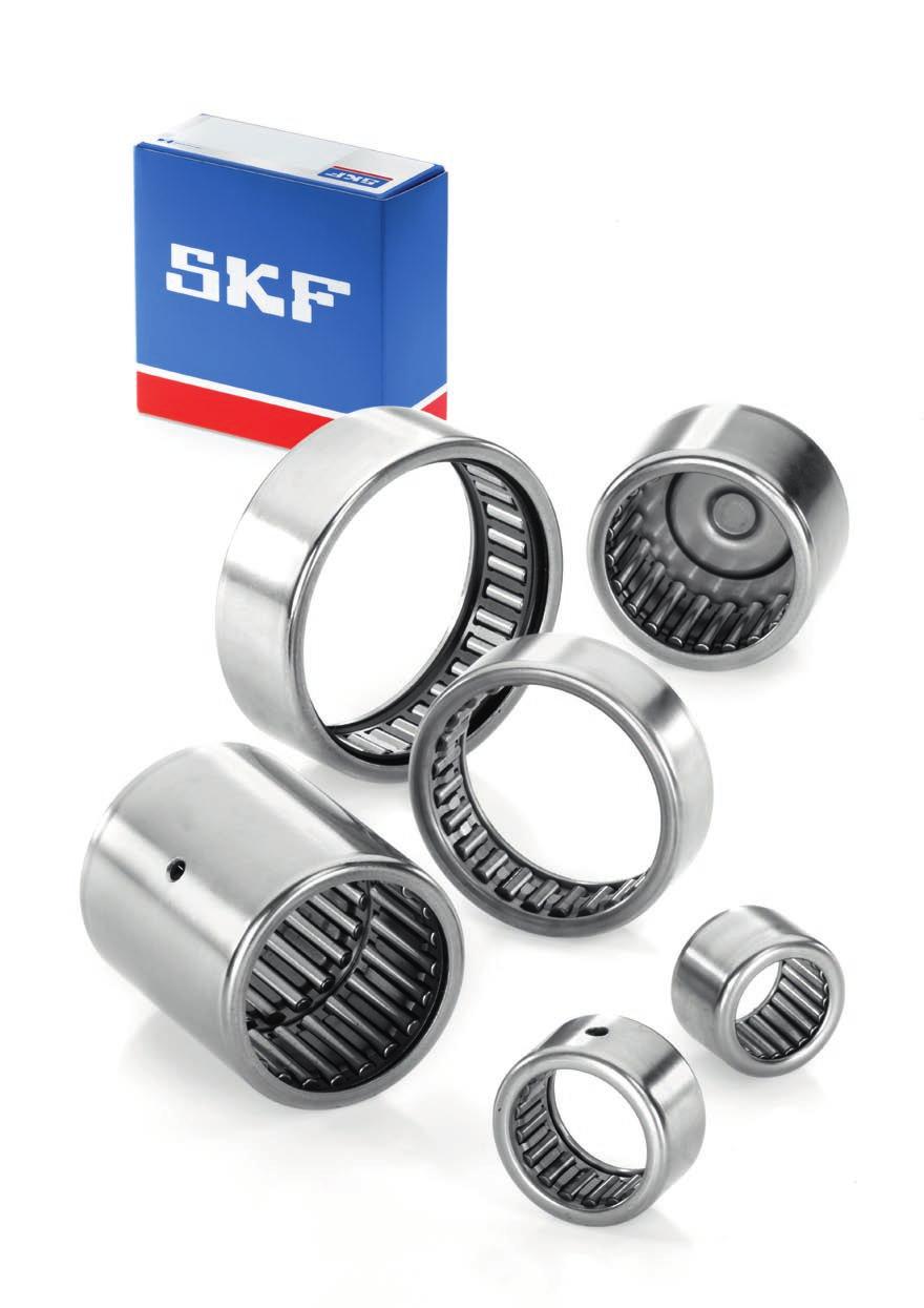
76
77 Drawn cup needle roller bearings Sealed drawn cup needle roller bearings Full complement drawn cup needle roller bearings Dimensions Tolerances Misalignment Cages Shaft and housing tolerances Operational clearance Mounting instructions Static safety factor Supplementary designations Product tables Drawn cup needle roller bearings
78 Drawn cup needle roller bearings Drawn cup needle roller bearings, as the name suggests, are needle roller bearings with a deep drawn, thin-walled outer ring with either open ends or a closed end. They are characterized by a very low sectional height and high load carrying capacity. Drawn cup needle roller bearings are typically used in applications where the housing bore cannot be used as a raceway for a needle roller and cage assembly, but where a very compact and economical bearing arrangement is required. Generally, drawn cup needle roller bearings have a recommended maximum operating temperature of 140 C, unless otherwise stated in the relevant sections in this chapter. The maximum operating temperature is limited by the seal and cage materials and the applied grease. SKF supplies a wide assortment of drawn cup needle roller bearings. This includes: drawn cup needle roller bearings with open ends ( fig. 1) drawn cup needle roller bearings with a closed end ( fig. 2) full complement drawn cup needle roller bearings with open ends ( fig. 3) Drawn cup needle roller bearings with a closed end are suitable for bearing arrangements at the ends of shafts. The profiled design of the closed end accommodates small axial guidance forces. Drawn cup needle roller bearings generally run directly on the shaft. However, in cases where the shaft cannot be hardened and ground, they can be combined with an inner ring ( fig. 4). The drawn cup of hardened steel and the needle roller and cage assembly of these bearings form a non-separable unit. The space available for lubricant is large enough to enable long relubrication intervals. Typically, drawn cup needle roller bearings have a single row of rollers. However, wide sizes incorporate two needle roller and cage assemblies immediately adjacent to each other with a lubrication hole in the outer ring ( fig. 5). On request, any single row drawn cup needle roller bearing for shaft diameters of 7 mm and above can be supplied with a lubrication hole in the outer ring ( fig. 6). Drawn cup needle roller bearing with open ends HK series Drawn cup needle roller bearing with a closed end BK series Fig. 1 Fig. 2 Fig. 3 Full complement drawn cup needle roller bearing with open ends HN series 76
79 Drawn cup needle roller bearing combined with an inner ring and an external seal Fig. 4 Drawn cup needle roller bearing combined with a needle roller thrust bearing, AXW series Fig. 7 3 Fig. 5 Wide size drawn cup needle roller bearing, double row, with a lubrication hole Drawn cup needle roller bearings are mounted with an interference fit in the housing bore. Therefore, shoulders or snap rings are not required to locate the bearing axially so the design of the housing bore is simple and can be produced economically. To accommodate combined radial and axial loads ( fig. 7), drawn cup needle roller bearings of certain sizes can be combined with a needle roller thrust bearing with a centring spigot, AXW series. Fig. 6 Drawn cup needle roller bearing with a closed end and lubrication hole 77
80 Drawn cup needle roller bearings Sealed drawn cup needle roller bearings For applications where a sufficiently efficient seal is not available, or cannot be used for space reasons, drawn cup needle roller bearings can also be supplied with integral lip seals. These include: drawn cup needle roller bearings with open ends, sealed on one side, designation suffix RS ( fig. 8), available for shaft diameters ranging from 8 mm to 50 mm drawn cup needle roller bearings with open ends, sealed on both sides, designation suffix.2rs ( fig. 9), available for shaft diameters ranging from 8 mm to 50 mm sealed drawn cup needle roller bearings with a closed end, designation suffix RS ( fig. 10), available for shaft diameters ranging from 10 mm to 25 mm The integral seals are contact seals made of polyurethane (AU), fluoro rubber (FKM) or acrylonitrile-butadiene rubber (NBR). The use of a sealed drawn cup needle roller bearing is, under normal conditions, an extremely costeffective solution to exclude solid contaminants and moisture and retain the lubricant in the bearing. The permissible operating temperature range for sealed bearings is 30 to +100 C. Drawn cup needle roller bearing with open ends, sealed on one side HK.. RS series Drawn cup needle roller bearing with open ends, sealed on both sides Fig. 8 Fig. 9 Initial grease fill and relubrication Sealed drawn cup needle roller bearings are filled at the factory with a high-quality grease that has good corrosion inhibiting properties. The relatively large quantity of grease in the bearings means they can be operated for long periods before relubrication is required. SKF recommends using SKF LGWA 2 grease for relubrication. For additional information about greases, refer to the section Lubrication, starting on page 52 and table 1 on page 54. HK...2RS series Sealed drawn cup needle roller bearing with a closed end Fig. 10 BK.. RS series 78
81 Full complement drawn cup needle roller bearings Full complement drawn cup needle roller bearings with open ends ( fig. 3, page 76) are suitable for very heavy radial loads at moderate speeds. Initial grease fill and relubrication A special grease is used to secure the rollers during transportation, however, this grease does not provide sufficient long term lubri cation. Therefore, relubrication after mounting may be necessary. Depending on the required consistency class, SKF recommends SKF LGEP 2 or SKF LGMW 1 grease for relubrication. For additional information and characteristics ( table 2, page 54) of the initial grease fill and the greases for relubrication, refer to the section Lubrication, starting on page 52 or contact the SKF application engineering service. Dimensions The boundary dimensions of drawn cup needle roller bearings are in accordance with ISO 3245:2007, as far as they have been standardized. Tolerances The dimensional accuracy of drawn cup needle roller bearings cannot be checked until they have been mounted, because the thin-walled outer ring may be slightly out-of-round. Only after the bearing has been pressed into a housing bore that is machined to the recommended tolerance classes can the outer ring obtain its correct form, which is crucial for bearing performance. To check the inside diameter F w of the roller set, the bearing must first be pressed into a thick-walled gauge ring with a bore diameter as listed in table 1. A measuring mandrel can then be used to check the inside diameter deviation. The permissible deviations are also listed in the table. The tolerance values listed are in accordance with ISO 3245:2007, as far as they have been standardized. The width tolerance is 0/ 0,3 mm for all drawn cup needle roller bearing sizes. Table 1 Tolerances for drawn cup needle roller bearings Bearing Gauge ring Deviations from Inside Outside Bore nominal inside diameter diameter diameter diameter F w D (measured) high low mm mm µm 3 6,5 6, , , , , , , , , , , , , , , , , , , , , , , , , , , , Paired mounting If drawn cup needle roller bearings are to be mounted immediately adjacent to each other, the deviations from the nominal internal diameter must be the same for both bearings if they are to share the load equally. 3 79
82 Drawn cup needle roller bearings Misalignment The ends of the needle rollers are relieved slightly to modify the line contact between the raceways and the rollers. This provides favourable load distribution in the bearing and minimizes damaging edge stresses. It also enables single row drawn cup needle roller bearings to accommodate a small amount of misalignment, approximately 1 min of arc between the shaft and housing. The detrimental effects of misalignment increase with increasing bearing width and load. For additional information, contact the SKF application engineering service. Cages SKF drawn cup needle roller bearings are fitted, as standard, with a sheet steel cage ( fig. 11), except for those identified by the designation suffix TN. These have an injection moulded, glass fibre reinforced polyamide 66 cage ( fig. 12). Sheet steel cage Polyamide 66 cage Fig. 11 Fig. 12 Note Drawn cup needle roller bearings with a polyamide 66 cage can be operated at temperatures up to +120 C. The lubricants generally used for rolling bearings do not have a detrimental effect on cage properties. Exceptions are a few synthetic oils and greases with a synthetic oil base and lubricants containing a high proportion of EP additives when used at high temperatures. For bearing arrangements that will operate at continuously high temperatures or under arduous conditions, SKF recommends using bearings with a steel cage. For detailed information about the temperature resistance and the applicability of cages, refer to the section Cage materials, starting on page 44. Shaft and housing tolerances Drawn cup needle roller bearings need a housing bore that has a good dimensional form and accuracy. For these bearings, to obtain the ne cessary interference fit in the housing, the tolerance classes listed in table 2 must be applied. The cylindricity of the housing bore should be within IT5/2 tolerance grade and the shaft raceway should be within IT3 tolerance grade. Operational clearance When the recommended tolerance classes are applied, the inside diameter F w (diameter under the rollers) will be approximately within F8 tolerance class. This, together with the recommended shaft tolerance class, which is also listed in table 2, will reach a suitable (medium) oper ational clearance in the range of C2 to C3 radial internal clearance. The clearance value depends on the shaft diameter, the operating 80
83 temperature, and on the raceway diameter when combined with an inner ring. Mounting instructions Drawn cup needle roller bearings should be mounted with a heavy interference fit in the housing bore. Therefore, SKF recommends mounting them using a mounting dolly ( fig. 13). An O-ring provides a simple means of retaining the bearing on the mounting dolly. The stamped side face of drawn cup needle roller bearings should preferably abut the flange of the mounting dolly. If grease lubrication is going to be used, the bearing should be lubricated before mounting. Table 2 Shaft and housing tolerance classes Housing Tolerance classes material 1) Housing Raceway Shaft bore on the inner ring seat 2) shaft seat Steel, cast iron N6 h5 k5 N7 h6 j6 Light alloy R6 h5 k5 R7 h6 j6 1) For housings that are not rigid, the shaft tolerance giving the desired operational clearance must be determined by trial and error. 2) The accuracy of cylindrical form to ISO for the housing bore must correspond to IT5/2 tolerance grade. 3 Note Special care should be taken to prevent the bearings from skewing or tilting when they are being pressed into the housing. Otherwise the rollers and raceways could easily be damaged. Mounting dolly Fig. 13 Static safety factor SKF recommends applying a static safety factor of 3 or larger, i.e. s 0 = C 0 /P Supplementary designations The designation suffixes used to identify certain features of SKF drawn cup needle roller bearings are explained in the following. AS1 One lubrication hole in the outer ring H.. Needle roller bearing without an inner ring, with reduced inside diameter (under rollers) tolerance, followed by tolerance limits in µm, e.g. H RS Contact seal on one side of the bearing.2rs Contact seal on both sides of a drawn cup needle roller bearing with open ends TN Injection moulded cage of glass fibre re inforced polyamide 66 D 0,2 0,3 F w 0,025 81
84 Drawn cup needle roller bearings F w 3 9 mm C r 2 r1 C 1 D F w HK BK HK.. RS HK...2RS Principal Basic load ratings Fatigue Speed ratings Mass Designation dimensions dynamic static load limit Reference Limiting speed speed F w D C C C 0 P u mm kn kn r/min kg 3 6,5 6 1,23 0,88 0, ,0010 HK 0306 TN 6,5 6 1,23 0,88 0, ,0010 BK 0306 TN ,76 1,37 0, ,0020 HK ,76 1,37 0, ,0021 BK ,38 2,08 0, ,0020 HK ,38 2,08 0, ,0021 BK ,72 1,29 0, ,0015 HK ,01 1,73 0, ,0021 HK ,81 2,7 0, ,0025 HK ,81 2,7 0, ,0026 BK ,03 3,05 0, ,0026 HK ,03 3,05 0, ,0029 BK ,7 2,75 0, ,0027 HK ,7 2,75 0, ,0030 BK ,69 4,05 0, ,0030 HK ,7 2,75 0, ,0030 HK 0810 RS ,3 2,04 0, ,0032 HK RS ,69 4,05 0, ,0034 BK ,69 4,05 0, ,0031 HK 0812 RS ,7 2,75 0, ,0033 HK RS ,52 3,9 0, ,0030 HK ,13 4,8 0, ,0040 HK ,13 4,8 0, ,0043 BK ,12 6,4 0, ,0046 HK ,12 6,4 0, ,0049 BK
85 3.1 Dimensions Appropriate Appropriate inner ring 1) seal 2) Designation Designation F w C 1 r 1,2 min min mm 3 0,3 5,2 0,3 4 0,3 G S 6,4 0,3 G S 5 0,4 G S 7,2 0,4 G S 0,4 G S 6 0,4 G S 0,4 G S 7,4 0,4 G S 7 0,4 G S 7,4 0,4 G S 8 0,4 G ,4 0,4 G ,4 IR G ,4 IR ,4 8,4 0,4 IR G ,4 0,4 IR ,4 G ,4 IR G ,2 0,4 IR G ,4 IR G ,4 0,4 IR G ) For additional information, refer to the section Needle roller bearing inner rings, starting on page ) For additional information, refer to the section Radial shaft seals with a low cross sectional height, starting on page
86 Drawn cup needle roller bearings F w mm C r 2 r1 C 1 D F w HK BK HK.. RS HK...2RS Principal Basic load ratings Fatigue Speed ratings Mass Designation dimensions dynamic static load limit Reference Limiting speed speed F w D C C C 0 P u mm kn kn r/min kg ,29 5,3 0, ,0041 HK ,82 11,4 1, ,0046 HN ,29 5,3 0, ,0043 BK ,39 6,95 0, ,0048 HK ,29 5,3 0, ,0042 HK 1012 RS ,19 3,55 0, ,0043 HK RS ,39 6,95 0, ,0050 BK ,29 5,3 0, ,0043 BK 1012 RS ,29 5,3 0, ,0046 HK RS ,6 9 1, ,0060 HK ,6 9 1, ,0062 BK ,84 6,4 0, ,0046 HK ,48 13,7 1, ,0053 HN ,84 6,4 0, ,0052 BK ,27 7,35 0, ,0090 HK ,52 15,3 1, ,011 HN ,27 7,35 0, ,010 BK ,27 7,35 0, ,010 HK 1214 RS ,84 6,4 0, ,0080 HK RS ,27 7,35 0, ,011 HK RS ,6 8 0, ,010 HK ,6 8 0, ,011 BK ,82 8,65 0, ,011 HK ,5 17,6 2, ,012 HN ,82 8,65 0, ,012 BK ,82 8,65 0, ,012 HK 1414 RS ,82 8,65 0, ,013 BK 1414 RS ,82 8,65 0, ,013 HK RS 84
87 3.1 BK.. RS HN Dimensions Appropriate Appropriate inner ring 1) seal 2) Designation Designation F w C 1 r 1,2 min min mm 10 0,4 LR/IR G ,4 LR/IR G ,4 0,4 LR/IR G ,4 IR G ,4 IR ,4 10,4 0,4 IR G ,4 0,4 0,4 IR ,4 IR G ,4 0,4 IR G ,4 LR/IR G ,4 LR/IR G ,4 0,4 LR/IR G ,8 LR/IR G/SD ,8 LR/IR G/SD ,3 0,8 LR/IR G/SD ,8 0,4 0,8 IR ,8 LR/IR G ,3 0,8 LR/IR G ,8 IR G/SD ,8 IR G/SD ,3 0,8 IR G/SD ,8 IR ,3 0,8 IR ,8 IR ) For additional information, refer to the section Needle roller bearing inner rings, starting on page ) For additional information, refer to the section Radial shaft seals with a low cross sectional height, starting on page
88 Drawn cup needle roller bearings F w mm C r 2 r1 C 1 D F w HK BK HK.. RS HK...2RS Principal Basic load ratings Fatigue Speed ratings Mass Designation dimensions dynamic static load limit Reference Limiting speed speed F w D C C C 0 P u mm kn kn r/min kg ,65 9,5 1, ,011 HK ,65 9,5 1, ,013 BK , , ,012 HK 1514 RS ,1 14,6 1, ,015 HK , , ,015 HK RS ,5 28 3, ,014 HN ,1 14,6 1, ,017 BK ,1 14,6 1, ,016 HK 1518 RS ,1 14,6 1, ,018 HK RS , ,020 HK ) ,37 9,8 1, ,012 HK ,2 20,4 2, ,013 HN ,37 9,8 1, ,014 BK ,37 9,8 1, ,013 HK 1614 RS ,37 9,8 1, ,015 BK 1614 RS ,5 15,6 1, ,016 HK ,37 9,8 1, ,014 HK RS ,5 15,6 1, ,018 BK ,6 1, ,018 HK RS ,8 19,6 2, ,022 HK ) ,8 19,6 2, ,024 BK ) ,65 10,6 1, ,012 HK ,92 11,2 1, ,013 HK ,92 11,2 1, ,015 BK ,92 11,2 1, ,014 HK 1814 RS ,2 17,6 2, ,018 HK ,92 11,2 1, ,015 HK RS ,1 33,5 3, ,020 HN ,2 17,6 2, ,020 BK ) Double row, outer ring with a lubrication hole 86
89 3.1 BK.. RS HN HK (double row) BK (double row) Dimensions Appropriate Appropriate inner ring 1) seal 2) Designation Designation F w C 1 r 1,2 min min mm 15 0,8 LR/IR G/SD ,3 0,8 LR/IR G/SD ,8 LR/IR ,8 LR/IR G/SD ,8 LR/IR ,8 LR/IR G/SD ,3 0,8 LR/IR G/SD ,8 0,8 LR/IR ,8 LR/IR G/SD ,8 IR G/SD ,8 IR G/SD ,3 0,8 IR G/SD ,8 IR ,3 0,8 IR ,8 IR G/SD ,8 IR ,3 0,8 IR G/SD ,8 IR ,8 IR G/SD ,3 0,8 IR G/SD ,8 G/SD ,8 LR G/SD ,3 0,8 LR G/SD ,8 LR/IR ,8 LR/IR G/SD ,8 LR/IR ,8 LR/IR G/SD ,3 0,8 LR/IR G/SD ) For additional information, refer to the section Needle roller bearing inner rings, starting on page ) For additional information, refer to the section Radial shaft seals with a low cross sectional height, starting on page
90 Drawn cup needle roller bearings F w mm C r 2 r1 C 1 D F w HK BK HK.. RS HK...2RS Principal Basic load ratings Fatigue Speed ratings Mass Designation dimensions dynamic static load limit Reference Limiting speed speed F w D C C C 0 P u mm kn kn r/min kg ,16 8,5 0, ,012 HK ,42 12,5 1, ,014 HK ,3 20,4 2, ,019 HK ,42 12,5 1, ,018 HK RS ,8 36,5 4, ,022 HN ,3 20,4 2, ,022 BK ,3 20,4 2, ,021 HK 2018 RS ,3 20,4 2, ,024 BK 2018 RS ,1 26,5 3, ,024 HK ,3 20,4 2, ,023 HK RS ,9 48 5, ,030 HN ,1 26,5 3, ,027 BK ) ,9 40,5 4, ,035 HK ) ,21 10,6 1, ,013 HK ,8 13,7 1, ,015 HK ,8 13,7 1, ,018 BK ,8 13,7 1, ,016 HK 2214 RS ,4 2, ,021 HK ,8 13,7 1, ,018 HK RS ,4 2, ,024 BK ,4 2, ,024 HK 2218 RS ,7 29 3, ,026 HK ,4 2, ,026 HK RS 1) Double row, outer ring with a lubrication hole 88
91 3.1 BK.. RS HN HK (double row) BK (double row) Dimensions Appropriate Appropriate inner ring 1) seal 2) Designation Designation F w C 1 r 1,2 min min mm 20 0,8 IR IS1 G/SD ,8 IR G/SD ,8 LR/IR G/SD ,8 LR/IR ,8 LR/IR G/SD ,3 0,8 LR/IR G/SD ,8 LR/IR ,3 0,8 LR/IR ,8 LR/IR G/SD ,8 LR/IR ,8 LR/IR G/SD ,3 0,8 LR/IR G/SD ,8 LR/IR G/SD ,8 IR G/SD ,8 IR G/SD ,3 0,8 IR G/SD ,8 IR ,8 IR G/SD ,8 IR ,3 0,8 IR G/SD ,8 IR ,8 IR G/SD ,8 IR ) For additional information, refer to the section Needle roller bearing inner rings, starting on page ) For additional information, refer to the section Radial shaft seals with a low cross sectional height, starting on page
92 Drawn cup needle roller bearings F w mm C r 2 r1 C 1 D F w HK BK HK.. RS HK...2RS Principal Basic load ratings Fatigue Speed ratings Mass Designation dimensions dynamic static load limit Reference Limiting speed speed F w D C C C 0 P u mm kn kn r/min kg ,5 15,3 1, ,020 HK ,1 24 2, ,027 HK ,5 15,3 1, ,027 HK RS ,1 24 2, ,032 BK ,1 24 2, ,029 HK 2518 RS ,1 24 2, ,034 BK 2518 RS , ,033 HK ,1 24 2, ,031 HK RS ,4 60 7, ,040 HN , ,038 BK , ,040 HK RS ,2 45 5, ,044 HK ,2 45 5, ,048 BK ,2 45 5, ,047 HK RS , ,064 HK ) , ,068 BK ) ,7 26,5 3, ,029 HK ,7 26,5 3, ,031 HK 2818 RS ,1 36,5 4, ,036 HK ,7 26,5 3, ,034 HK RS ,1 68 8, ,044 HN ,7 18,3 2, ,023 HK ,7 18,3 2, ,028 BK ,5 29 3, ,031 HK ,7 18,3 2, ,031 HK RS ,5 29 3, ,038 BK ,5 29 3, ,037 HK 3018 RS ,9 40 4, ,039 HK ,5 29 3, ,036 HK RS ,9 40 4, ,047 BK ,8 46,5 5, ,042 HK ,9 40 4, ,044 HK RS , ,051 HK , ,058 BK ,8 80 9, ,076 HK ) ,8 80 9, ,084 BK ) 1) Double row, outer ring with a lubrication hole 90
93 3.1 BK.. RS HN HK (double row) BK (double row) Dimensions Appropriate Appropriate inner ring 1) seal 2) Designation Designation F w C 1 r 1,2 min min mm 25 0,8 LR G ,8 LR / IR G ,8 LR / IR ,3 0,8 0,8 LR/IR ,3 0,8 LR / IR ,8 LR/IR G ,8 LR/IR ,8 LR/IR G ,3 0,8 LR/IR G ,8 LR/IR ,8 LR/IR G ,3 0,8 LR/IR G ,8 IR ,8 LR/IR G ,3 0,8 LR/IR G ,8 IR G/SD ,8 LR/IR ,8 LR/IR G/SD ,8 LR/IR ,8 LR/IR G/SD ,8 LR G/SD ,3 0,8 LR G/SD ,8 LR / IR G/SD ,8 LR / IR ,3 0,8 LR / IR G/SD ,8 LR/IR ,8 LR/IR G/SD ,8 LR/IR ,3 0,8 LR/IR G/SD ,8 G/SD ,8 LR/IR ,8 LR/IR G/SD ,3 0,8 LR/IR G/SD ,8 LR/IR G/SD ,3 0,8 LR/IR G/SD ) For additional information, refer to the section Needle roller bearing inner rings, starting on page ) For additional information, refer to the section Radial shaft seals with a low cross sectional height, starting on page
94 Drawn cup needle roller bearings F w mm C r 2 r1 C 1 D F w HK BK HK.. RS HK...2RS Principal Basic load ratings Fatigue Speed ratings Mass Designation dimensions dynamic static load limit Reference Limiting speed speed F w D C C C 0 P u mm kn kn r/min kg , ,041 HK ,4 54 6, ,049 HK ,5 21,6 2, ,027 HK , ,036 HK ,5 21,6 2, ,032 HK RS , ,039 HK 3518 RS ,9 46,5 5, ,044 HK , ,041 HK RS , , ,054 HN ,9 46,5 5, ,053 BK ,4 24,5 2, ,030 HK , ,039 HK ,4 24,5 2, ,037 HK RS , ,045 HK 4018 RS ,2 53 6, ,054 HK , ,048 HK RS , , ,061 HN ,2 53 6, ,062 BK ,2 27,5 3, ,033 HK ,5 43 5, ,046 HK ,5 43 5, ,050 HK 4518 RS , ,056 HK ,5 43 5, ,054 HK RS , , ,066 HN , ,072 BK ,085 HN ,2 63 7, ,070 HK , , ,085 HN ,2 63 7, ,076 HK 5022 RS ,2 63 7, ,081 HK RS , , ,090 HK , , ,11 HN
95 3.1 HN Dimensions Appropriate Appropriate inner ring 1) seal 2) Designation Designation F w C 1 r 1,2 min min mm 32 0,8 0,8 35 0,8 LR G/SD ,8 LR / IR G/SD ,8 LR / IR ,8 LR/IR ,8 LR/IR G/SD ,8 LR/IR ,8 LR/IR G/SD ,3 0,8 LR/IR G/SD ,8 LR G/SD ,8 LR / IR G/SD ,8 LR / IR ,8 LR/IR ,8 LR/IR G/SD ,8 LR/IR ,8 LR/IR G/SD ,3 0,8 LR/IR G/SD ,8 G/SD ,8 LR / IR G/SD ,8 LR/IR ,8 LR/IR G/SD ,8 LR/IR ,8 LR/IR G/SD ,3 0,8 LR/IR G/SD ,8 G/SD ,8 LR / IR IS1 G/SD ,8 LR/IR IS1 G/SD ,8 LR/IR ,8 LR/IR ,8 LR/IR G/SD ,8 LR/IR G/SD ) For additional information, refer to the section Needle roller bearing inner rings, starting on page ) For additional information, refer to the section Radial shaft seals with a low cross sectional height, starting on page
96 Drawn cup needle roller bearings F w mm C r 2 r1 D F w HK Principal Basic load ratings Fatigue Speed ratings Mass Designation dimensions dynamic static load limit Reference Limiting speed speed F w D C C C 0 P u mm kn kn r/min kg ,3 67 8, ,074 HK , , ,11 HK ,6 32 3, ,049 HK ,9 75 9, ,081 HK , ,14 HK
97 3.1 Dimensions Appropriate Appropriate inner ring 1) seal 2) Designation Designation F w r 1,2 min mm 55 0,8 LR G ,8 G ,8 0,8 0,8 1) For additional information, refer to the section Needle roller bearing inner rings, starting on page ) For additional information, refer to the section Radial shaft seals with a low cross sectional height, starting on page
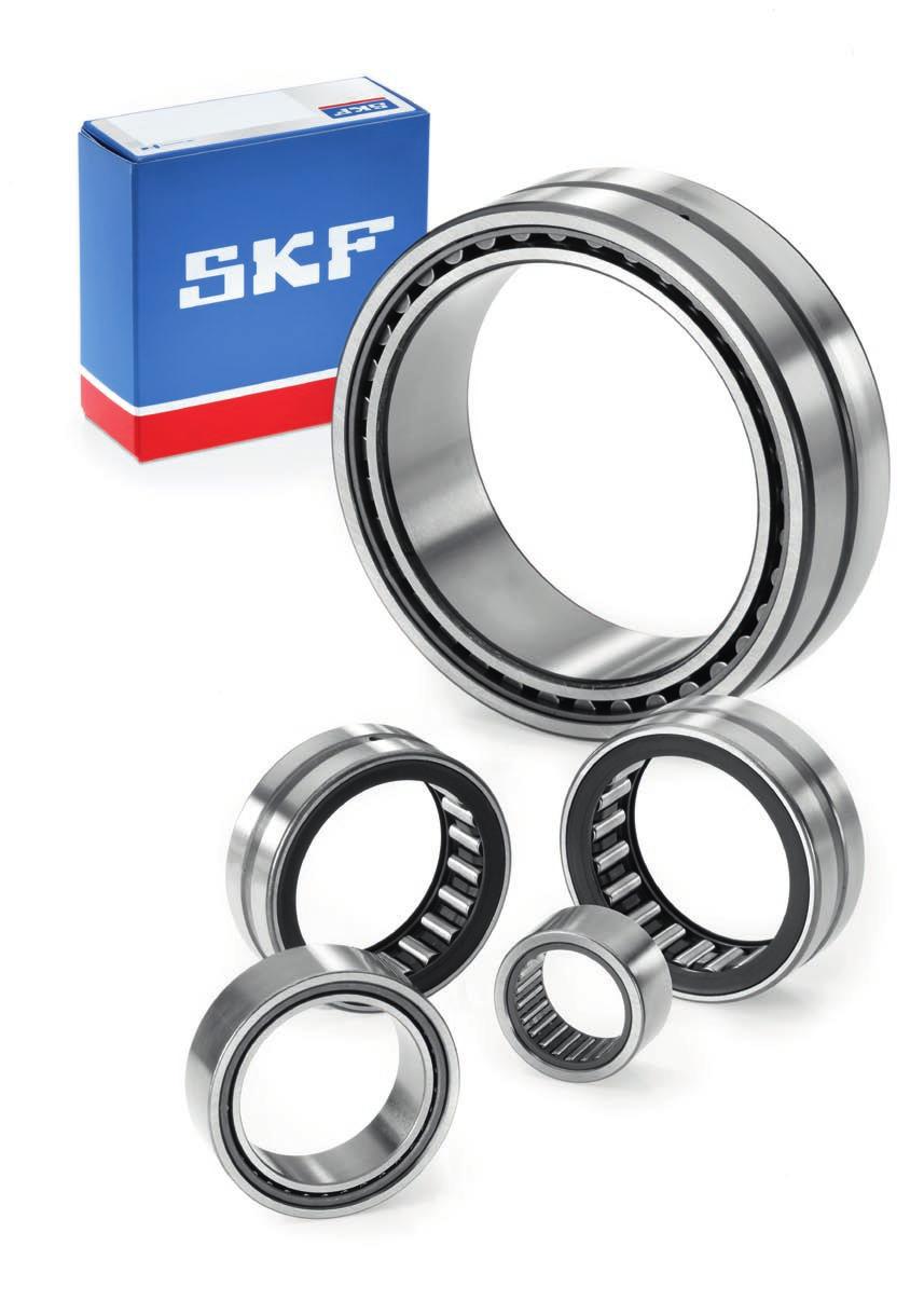
98
99 Needle roller bearings with machined rings Needle roller bearings with machined rings with flanges Needle roller bearings with machined rings without flanges Dimensions Tolerances Internal clearance Misalignment Cages Shaft and housing tolerances Supplementary designations Product tables Needle roller bearings with machined rings with flanges, without an inner ring Needle roller bearings with machined rings with flanges, with an inner ring Needle roller bearings with machined rings without flanges, without an inner ring Needle roller bearings with machined rings without flanges, with an inner ring
100 Needle roller bearings with machined rings Needle roller bearings with machined rings made of carbon chromium bearing steel have a low sectional height and a very high load carrying capacity for their size. They may be used with or without an inner ring, depending on the application. Needle roller bearings without an inner ring ( fig. 1) are an excellent choice for compact bearing arrangements if the shaft can be hardened and ground. Eliminating the need for a separate inner ring enables a larger shaft diameter and a stiffer arrangement. Axial displacement of the shaft relative to the housing is only limited by the width of the raceway on the shaft. By machining the shaft raceways to the appropriate dimensional and form accuracy, it is possible to obtain bearing arrangements with heightened running accuracy. For additional information, refer to the section Raceways on shafts and in housings on page 50 and to Internal clearance on page 42. Needle roller bearings with an inner ring ( fig. 2) are used for arrangements where it is not possible or uneconomical to harden and grind the shaft. Bearings with an inner ring only permit axial displacement of the shaft relative to the housing within certain limits. If the permissible axial displacement provided by a standard inner ring is insufficient, it is possible to use an extended inner ring. Extended inner rings can also provide an excellent counterface for the lips of external G or SD seals. For add itional information, refer to the section Needle roller bearing components, starting on page 195. SKF supplies needle roller bearings in several designs and sizes: with flanges (closure rings or integral flanges) on the outer ring ( figs. 3 and 4), sealed ( fig. 5) or not sealed and with or without an inner ring without flanges on the outer ring ( fig. 6), not sealed and with or without an inner ring Needle roller bearing without an inner ring Needle roller bearing with an inner ring Needle roller bearing with inserted closure rings (for bearings with F w 10 mm) Fig. 1 Fig. 2 Fig. 3 To accommodate combined radial and axial loads, needle roller bearings of certain sizes can be combined with needle roller thrust bearings with a centring spigot, AXW series ( fig. 7). 98
101 Needle roller bearing with integral outer ring flanges (for bearings with F w 12 mm) Fig. 4 Needle roller bearing combined with a needle roller thrust bearing, AXW series Fig. 7 without an inner ring with an inner ring Fig. 5 Needle roller bearing, sealed 4 Fig. 6 Needle roller bearing without flanges on the outer ring 99
102 Needle roller bearings with machined rings Needle roller bearings with machined rings with flanges SKF needle roller bearings with flanges on the outer ring and with an outside diameter up to and including 17 mm (F w 10 mm), are manufactured with inserted closure rings. These bearings do not have a lubrication hole or an annular groove ( fig. 8). Larger bearings have integral flanges on the outer ring, an annular groove and, depending on the bearing size, one or more lubrication holes in the outer ring ( fig. 9). Needle roller bearings with flanges are generally designed as single row bearings. Bearings in the RNA 69 and NA 69 series, with an outside diameter D 52 mm, have two needle roller and cage assemblies ( fig. 10). The outer ring and cage assembly of a needle roller bearing with flanges form a non separable unit. Design with inserted closure rings, without a lubrication hole NK series (F w 10 mm) Design with integral flanges, with a lubrication hole and an annular groove Fig. 8 Fig. 9 NK series (F w 12 mm) NKS series RNA 48 series RNA 49 series RNA 69 series (D 47 mm) Fig. 10 Needle roller bearing, double row RNA series (D 52 mm) 100
103 Sealed bearings Single row bearings, in the RNA 49 and NA 49 series, are also available with a contact seal on one ( fig. 11) or both sides ( fig. 12). The seals are made of acrylonitrile-butadiene rubber (NBR) that efficiently protects the bearing against the entry of contaminants and retains the lubricant in the bearing. The operating temperature range for sealed needle roller bearings with machined rings, which is limited by the seal material and the grease fill, is 20 C to +100 C. The inner ring of sealed bearings is 1 mm wider than the outer ring. This maintains the efficiency of the seals even when a small amount of axial displacement occurs. Needle roller bearing, sealed on one side NA 49.. RS series Fig. 11 Initial grease fill and relubrication Sealed needle roller bearings with machined rings are filled at the factory with a high-quality grease with good rust inhibiting properties. Because these bearings can hold a relatively large quantity of grease, they can be operated for long periods before relubrication is required. The lubrication groove and lubrication hole in the outer ring enable the lubricant to reach the bearing cavity during relubrication. The inner ring is also provided with a lubrication hole so that the bearing can be relubricated either via the outer or inner ring, depending on the application. SKF recommends SKF LGWA 2 grease for relubrication. For additional information about greases, refer to the section Lubrication, starting on page 52. Needle roller bearing, sealed on both sides NA RS series Fig External seals SKF supplies an assortment of radial shaft seals that can be used as external seals. Extended inner rings can be used if the inner ring raceway is to serve as a counterface for a seal adjacent to the bearing. Appropriate seals are listed in the product tables, when available. For additional information, refer to the section Needle roller bearing components, starting on page
104 Needle roller bearings with machined rings Needle roller bearings with machined rings without flanges Needle roller bearings without flanges are completely separable, i.e. the outer ring, the needle roller and cage assembly and the inner ring can all be mounted separately. In many applications, this makes mounting a great deal easier. The needle roller and cage assembly can either be mounted together with the outer ring or with the shaft or inner ring, depending on the arrangement design. It can also be inserted between the outer ring and shaft or inner ring as the final step. However, needle roller and cage assemblies and bearing outer rings must always be kept together as supplied. SKF needle roller bearings without flanges are available as single row ( fig. 13) or double row bearings ( fig. 14). Double row bearings have two needle roller and cage assemblies arranged adjacent to each other. They have an annular groove and a lubrication hole in the outer ring to enable efficient lubrication. To provide efficient lubrication for needle roller bearings with an inner ring, SKF supplies some bearings with one lubrication hole in the inner ring. These bearings are listed in the product table. The cage of needle roller bearings without flanges must be axially guided by fine turned and burr-free surfaces on adjacent machine components. Recommended dimensions for these surfaces are listed in the product tables. Dimensions The boundary dimensions of SKF needle roller bearings with machined rings in the RNA 48, RNA 49, RNA 69, NA 48, NA 49 and NA 69 series are in accordance with ISO The dimensions of the other needle roller bearings do not adhere to any national or international standards, but are common in the market. Tolerances SKF supplies needle roller bearings with machined rings to Normal tolerances in accordance with ISO 492:2002, as standard. On request, needle roller bearings with higher accuracy to tolerance P6 or P5 specifications can be supplied. For bearing arrangements with higher accur acy, inner rings with a pre ground raceway and a machining allowance can be supplied, but must be finish ground after mounting. The inside diameter F w of the needle roller and cage assembly, when the rollers are in contact with the outer ring raceway, lies within the limits of F6 tolerance class ( table 1) before the bearings are mounted. On request, SKF supplies needle roller bearings without an inner ring and with reduced inside diameter tolerances. These bearings are identified by the designation suffix H followed by a figure com bination that gives the actual maximum and minimum values in μm for the deviation from the nominal inside diameter F w, e.g. H Needle roller bearing, single row, with an inner ring Fig. 13 Needle roller bearing, double row, without an inner ring Fig. 14 NAO series RNAO series 102
105 Internal clearance SKF needle roller bearings with an inner ring have Normal radial internal clearance as standard. The clearance values are listed in table 7 on page 42 and are in accordance with ISO :2009. They are valid for unmounted bearings under zero measuring load. For needle roller bearings without an inner ring, a suitable internal clearance is achieved by selecting the appropriate tolerance class for the raceway diameter. Recommended values are listed in table 2. The recommendations apply, pro vided the housing bore is not tighter than a K7 tolerance class. Misalignment The ends of the needle rollers are relieved slightly to modify the line contact between the raceways and rollers. This provides favourable load distribution in the bearing and minimizes damaging edge stresses. It also enables needle roller bearings with machined rings to accommodate a small amount of misalignment, approximately 1 min of arc between the shaft and housing. The detrimental effects of misalignment increase with increasing bearing width and load. For additional information, contact the SKF application engineering service. 4 ISO tolerance class Nominal inside F6 tolerance class diameter F w over incl. high low mm µ μm Table 1 Shaft tolerance classes for needle roller bearings without an inner ring Nominal inside diameter Shaft tolerance classes for shaft raceways to give operational clearance F w lower medium higher over incl. side side mm 65 k5 h5 g k5 h5 f k5 g5 f k5 g5 e j5 g5 e j5 f6 e h5 f6 e g5 f6 d6 Table 2 103
106 Needle roller bearings with machined rings Machined steel cage Sheet steel cage Fig. 15 Fig. 16 Cages Depending on their size, SKF needle roller bearings with machined rings are fitted as standard with a machined steel ( fig. 15) or sheet steel cage ( fig. 16), no designation suffix. A number of bearings are fitted as standard with an injection moulded cage of glass fibre reinforced polyamide 66 ( fig. 17), designation suffix TN. Note Needle roller bearings with a polyamide 66 cage that are not sealed can be operated at temperatures up to 120 C. The lubricants generally used for rolling bearings do not have a detrimental effect on cage properties. Exceptions are a few synthetic oils and greases with a synthetic oil base and lubricants containing a high proportion of EP additives when used at high temperatures. For bearing arrangements that operate at continuously high temperatures or under arduous conditions, SKF recommends using bearings with a steel cage. For additional information about the tempera ture resistance and the applicability of cages, refer to the section Cage materials, starting on page 44. Polyamide 66 cage Fig. 17 Shaft and housing tolerances The shaft tolerances for SKF needle roller bearings with machined rings should be in accordance with the fits that are listed in table 3. When needle roller bearings with an inner ring are used under conditions of point load and mounted with a loose fit, the inner ring seat should be machined to h6 or g6 tolerance class. When the load rotates, the inner rings should have an interference fit. Sufficient interference can be obtained if the recommended shaft tolerance classes ( table 3) are applied. For information about housing tolerances for needle roller bearings with an inner ring, refer to the SKF General Catalogue, section Application of bearings/recommended fits. 104
107 Table 3 Fits for needle roller bearings with machined rings with an inner ring on solid steel shafts Conditions Shaft Tolerance diameter class mm Rotating inner ring load or direction of load indeterminate Light and 10 k5 variable loads (10) to 25 k6 (P 0,05 C) (25) to 100 m6 Normal to 25 k5 heavy loads (25) to 60 m6 (P > 0,05 C) (60) to 100 n6 (100) to 400 p6 1) Heavy to very (50) to 100 n6 1) heavy loads (100) to 200 p6 1) (P > 0,1 C) > 200 r6 1) Stationary inner ring load Easy axial displace- g6 ment of the inner ring on the shaft necessary Easy axial displace- h6 ment of the inner ring on the shaft unnecessary 1) Bearings with radial internal clearance greater than Normal may be necessary. Supplementary designations The designation suffixes used to identify certain features of SKF needle roller bearings are explained in the following. C2 C3 C4 CN H.. IS.. Bearing internal clearance smaller than Normal Radial internal clearance greater than Normal Radial internal clearance greater than C3 Bearing internal clearance Normal, only used together with an additional letter (H, L, M, P) that identifies a reduced or displaced clearance range Needle roller bearing without an inner ring, with reduced inside diameter (under rollers) tolerance, followed by tolerance limits in μm, e.g. H Needle roller bearing with one or more lubricating holes in the inner ring, a figure following indicates the number of holes ISR.. Needle roller bearing with an annular groove and one or more lubricating holes in the inner ring, a figure following indicates the number of holes P5 P6 Dimensional and running accuracy to ISO tolerance class 5 specifications (better than P6) Dimensional and running accuracy to ISO tolerance class 6 specifications (better than Normal) RS Contact seal of acrylonitrile-butadiene rubber (NRB) with or without sheet steel reinforcement on one side of the bearing.2rs RS contact seal on both sides of the TN bearing Injection moulded cage of glass fibre re inforced polyamide 66, rolling element centred 4 105
108 Needle roller bearings with machined rings with flanges, without an inner ring F w 5 16 mm C r 2 r 1 D F w NK (F w 10 mm) NK (F w 12 mm) RNA 49 RNA 6901 RNA 49.. RS RNA RS Principal Basic load ratings Fatigue Speed ratings Mass Designation dimensions dynamic static load Reference Limiting limit speed speed F w D C C C 0 P u mm kn kn r/min kg ,29 2 0, ,0031 NK 5/10 TN ,92 2,7 0, ,0037 NK 5/12 TN ,55 2,36 0, ,0047 NK 6/10 TN ,3 3,2 0, ,0057 NK 6/12 TN ,81 2,75 0, ,0069 NK 7/10 TN ,58 3,75 0, ,0082 NK 7/12 TN ,8 4,25 0, ,0087 NK 8/12 TN ,01 5,85 0, ,012 NK 8/16 TN ,4 5,2 0, ,010 NK 9/12 TN ,72 7,2 0, ,013 NK 9/16 TN ,4 5,4 0, ,010 NK 10/12 TN ,94 8 0, ,013 NK 10/16 TN ,71 8,15 0, ,012 NK 12/ , , ,016 NK 12/ ,8 10,4 1, ,017 RNA ,37 8,15 0, ,016 RNA 4900 RS ,37 8,15 0, ,016 RNA RS ,2 12,5 1, ,021 NK 14/ ,8 16,6 2, ,026 NK 14/ , ,022 NK 15/ ,8 18,3 2, ,027 NK 15/ ,9 12,2 1, ,017 RNA ,09 9,65 1, ,018 RNA 4901 RS ,09 9,65 1, ,018 RNA RS ,7 15,3 1, ,022 NK 16/ ,5 20 2, ,028 NK 16/ ,1 23,2 2, ,031 RNA
109 r a D a Dimensions Abutment and Appropriate seal 1) fillet dimensions Designation F w r 1,2 D a r a min max max mm mm ,15 8,8 0,1 G S 0,15 8,8 0,1 G S 6 0,15 10,8 0,1 G S 0,15 10,8 0,1 G S 7 0,3 12 0,3 G ,3 12 0,3 G ,3 13 0,3 G/SD ,3 13 0,3 G/SD ,3 14 0,3 G ,3 14 0,3 G ,3 15 0,3 G/SD ,3 15 0,3 G/SD ,3 17 0,3 G/SD ,3 17 0,3 G/SD ,3 20 0,3 G/SD ,3 20 0,3 0,3 20 0,3 0,3 20 0,3 G/SD ,3 20 0,3 G/SD ,3 21 0,3 G/SD ,3 21 0,3 G/SD ,3 22 0,3 G/SD ,3 22 0,3 0,3 22 0,3 0,3 22 0,3 G/SD ,3 22 0,3 G/SD ,3 22 0,3 G/SD ) For additional information, refer to the section Radial shaft seals with a low cross sectional height, starting on page 208. For additional information about SKF seals, refer to the SKF catalogue Industrial shaft seals. 107
110 Needle roller bearings with machined rings with flanges, without an inner ring F w mm C r 2 r1 D F w NK(S) RNA 49 RNA 69 RNA 49.. RS RNA RS Principal Basic load ratings Fatigue Speed ratings Mass Designation dimensions dynamic static load Reference Limiting limit speed speed F w D C C C 0 P u mm kn kn r/min kg ,1 16, ,024 NK 17/ ,1 22 2, ,030 NK 17/ ,8 17,6 2, ,025 NK 18/ ,1 23, ,031 NK 18/ ,4 19 2, ,026 NK 19/ ,5 25,5 3, ,032 NK 19/ ,2 15,3 1, ,022 RNA , , ,022 RNA 4902 RS , , ,022 RNA RS ,2 19,3 2, ,027 NK 20/ ,5 25,5 3, ,034 NK 20/ ,3 27 3, ,049 NKS ,2 27 3, ,040 RNA ,8 20,4 2, ,028 NK 21/ ,2 27 3, ,035 NK 21/ ,4 16,3 1, ,022 RNA ,52 12,9 1, ,023 RNA 4903 RS ,52 12,9 1, ,023 RNA RS ,2 21,6 2, ,030 NK 22/ ,9 29 3, ,037 NK 22/ ,7 30,5 3, ,042 RNA ,6 30 3, ,062 NKS ,4 24, ,032 NK 24/ ,5 4, ,040 NK 24/ ,5 4, ,066 NKS
111 r a D a Dimensions Abutment and Appropriate seal 1) fillet dimensions Designation F w r 1,2 D a r a min max max mm mm ,3 23 0,3 G/SD ,3 23 0,3 G/SD ,3 24 0,3 G/SD ,3 24 0,3 G/SD ,3 25 0,3 G/SD ,3 25 0,3 G/SD ,3 26 0,3 G/SD ,3 26 0,3 0,3 26 0,3 0,3 26 0,3 G/SD ,3 26 0,3 G/SD ,6 28 0,6 CR CRW1 R 0,3 26 0,3 G/SD ,3 27 0,3 G ,3 27 0,3 G ,3 28 0,3 G/SD ,3 28 0,3 0,3 28 0,3 0,3 28 0,3 G/SD ,3 28 0,3 G/SD ,3 28 0,3 G/SD ,6 31 0,6 CR CRW1 R 24 0,3 30 0,3 G/SD ,3 30 0,3 G/SD ,6 33 0,6 1) For additional information, refer to the section Radial shaft seals with a low cross sectional height, starting on page 208. For additional information about SKF seals, refer to the SKF catalogue Industrial shaft seals. 109
112 Needle roller bearings with machined rings with flanges, without an inner ring F w mm C r 2 r1 D F w NK(S) RNA 49 RNA 69 RNA 49.. RS RNA RS Principal Basic load ratings Fatigue Speed ratings Mass Designation dimensions dynamic static load Reference Limiting limit speed speed F w D C C C 0 P u mm kn kn r/min kg ,1 24, ,033 NK 25/ ,5 4, ,042 NK 25/ ,6 28 3, ,052 RNA ,4 22,4 2, ,056 RNA 4904 RS ,4 22,4 2, ,056 RNA RS ,2 53 6, ,10 RNA ,5 36 4, ,068 NKS ,7 26 3, ,034 NK 26/ ,4 34,5 4, ,042 NK 26/ ,5 4, ,052 NK 28/ ,9 60 7, ,082 NK 28/ ,3 32 4, ,050 RNA 49/ ,9 57 7, ,098 RNA 69/ , ,084 NKS ,6 42,5 5, ,050 NK 29/20 TN ,9 60 7, ,084 NK 29/ ,5 44 5, ,061 NK 30/20 TN , ,093 NK 30/30 TN ,2 34,5 4, ,061 RNA ,6 27,5 3, ,060 RNA 4905 RS ,6 27,5 3, ,060 RNA RS , ,11 RNA ,9 43 5, ,10 NKS , ,064 NK 32/20 TN ,1 65,5 8, ,10 NK 32/ ,1 36,5 4, ,073 RNA 49/ ,6 65,5 8, ,14 RNA 69/ ,1 46, ,11 NKS
113 r a D a Dimensions Abutment and Appropriate seal 1) fillet dimensions Designation F w r 1,2 D a r a min max max mm mm ,3 31 0,3 G/SD ,3 31 0,3 G/SD ,3 35 0,3 CR CRW1 R 0,3 35 0,3 0,3 35 0,3 0,3 35 0,3 CR CRW1 R 0,6 34 0,6 CR CRW1 R 26 0,3 32 0,3 G/SD ,3 32 0,3 G/SD ,3 35 0,3 G ,3 35 0,3 G ,3 37 0,3 0,3 37 0,3 0,6 38 0,6 CR CRW1 R 29 0,3 36 0,3 G ,3 36 0,3 G ,3 38 0,3 G/SD ,3 38 0,3 G/SD ,3 40 0,3 CR CRW1 R 0,3 40 0,3 0,3 40 0,3 0,3 40 0,3 CR CRW1 R 0,6 41 0,6 CR CRW1 R 32 0,3 40 0,3 G/SD ,3 40 0,3 G/SD ,3 43 0,3 G ,3 43 0,3 G ,6 43 0,6 CR CRW1 R 1) For additional information, refer to the section Radial shaft seals with a low cross sectional height, starting on page 208. For additional information about SKF seals, refer to the SKF catalogue Industrial shaft seals. 111
114 Needle roller bearings with machined rings with flanges, without an inner ring F w mm C r 2 r1 D F w NK(S) RNA 49 RNA 69 (D 47 mm) RNA 69 (D 52 mm) RNA 49.. RS RNA RS Principal Basic load ratings Fatigue Speed ratings Mass Designation dimensions dynamic static load Reference Limiting limit speed speed F w D C C C 0 P u mm kn kn r/min kg ,5 52 6, ,070 NK 35/20 TN , , ,11 NK 35/30 TN ,5 39 4, ,069 RNA ,3 32 3, ,069 RNA 4906 RS ,3 32 3, ,069 RNA RS ,9 75 9, ,13 RNA ,2 50 6, ,12 NKS ,1 46,5 5, ,077 NK 37/ ,9 76, ,11 NK 37/ ,9 54 6, ,12 NKS ,5 49 6, ,079 NK 38/ , , ,12 NK 38/ ,3 61 7, ,078 NK 40/20 TN , ,13 NK 40/ ,8 51 6, ,089 RNA 49/ , , ,16 RNA 69/ , ,13 NKS , ,086 NK 42/ ,1 86,5 11, ,13 NK 42/ ,9 54 6, ,11 RNA , ,11 RNA 4907 RS , ,11 RNA RS , , ,19 RNA ,5 55 6, ,086 NK 43/ , , ,13 NK 43/ ,1 61 7, ,14 NKS ,4 67 8, ,086 NK 45/20 TN , , ,14 NK 45/30 TN ,2 64 8, ,15 NKS ,2 61 7, ,095 NK 47/ , , ,14 NK 47/30 112
115 r a D a Dimensions Abutment and Appropriate seal 1) fillet dimensions Designation F w r 1,2 D a r a min max max mm mm ,3 43 0,3 G/SD ,3 43 0,3 G/SD ,3 45 0,3 CR CRW1 R 0,3 45 0,3 0,3 45 0,3 0,3 45 0,3 CR CRW1 R 0,6 46 0,6 CR CRW1 R 37 0,3 45 0,3 G/SD ,3 45 0,3 G/SD ,6 48 0,6 38 0,3 46 0,3 G/SD ,3 46 0,3 G/SD ,3 48 0,3 G/SD ,3 48 0,3 G/SD ,6 48 0,6 G/SD ,6 48 0,6 G/SD ,6 51 0,6 CR CRW1 R 42 0,3 50 0,3 G/SD ,3 50 0,3 G/SD ,6 51 0,6 CR CRW R 0,6 51 0,6 0,6 51 0,6 0,6 51 0,6 43 0,3 51 0,3 G ,3 51 0,3 G ,6 53 0,6 45 0,3 53 0,3 G/SD ,3 53 0,3 G/SD ,6 56 0,6 CR CRW1 R 47 0,3 55 0,3 0,3 55 0,3 1) For additional information, refer to the section Radial shaft seals with a low cross sectional height, starting on page 208. For additional information about SKF seals, refer to the SKF catalogue Industrial shaft seals. 113
116 Needle roller bearings with machined rings with flanges, without an inner ring F w mm C r 2 r1 D F w NK(S) RNA 49 RNA 69 RNA 49.. RS RNA RS Principal Basic load ratings Fatigue Speed ratings Mass Designation dimensions dynamic static load Reference Limiting limit speed speed F w D C C C 0 P u mm kn kn r/min kg ,9 71 9, ,14 RNA ,9 58,5 7, ,15 RNA 4908 RS ,9 58,5 7, ,15 RNA RS , ,26 RNA , , ,15 NK 50/25 TN , ,21 NK 50/35 TN ,9 72 9, ,16 NKS , ,18 RNA , ,16 RNA 4909 RS , ,16 RNA RS , , ,34 RNA , , ,18 NK 55/ , ,25 NK 55/ , ,22 NKS , ,16 RNA ,2 69,5 8, ,16 RNA 4910 RS ,2 69,5 8, ,16 RNA RS , ,31 RNA , , ,17 NK 60/25 TN , ,26 NK 60/ , , ,34 NKS , , ,26 RNA , ,47 RNA , ,22 NK 65/ , , ,31 NK 65/ ,36 NKS ,24 NK 68/ , ,34 NK 68/ , , ,28 RNA , ,49 RNA
117 r a D a Dimensions Abutment and Appropriate seal 1) fillet dimensions Designation F w r 1,2 D a r a min max max mm mm ,6 58 0,6 CR CRW1 R 0,6 58 0,6 0,6 58 0,6 0,6 58 0,6 50 0,6 58 0,6 G/SD ,6 58 0,6 G/SD CR CRW1 R 52 0,6 64 0,6 CR CRW1 R 0,6 64 0,6 0,6 64 0,6 0,6 64 0,6 55 0,6 64 0,6 0,6 64 0, CR CRW1 R 58 0,6 68 0,6 CR CRW1 R 0,6 68 0,6 0,6 68 0,6 0,6 68 0,6 60 0,6 68 0,6 0,6 68 0,6 1,1 73, CR CRW1 R ,6 74 0,6 0,6 74 0,6 1,1 78,5 1 CR CRW1 R 68 0,6 78 0,6 0,6 78 0, CR CRW1 R ) For additional information, refer to the section Radial shaft seals with a low cross sectional height, starting on page 208. For additional information about SKF seals, refer to the SKF catalogue Industrial shaft seals. 115
118 Needle roller bearings with machined rings with flanges, without an inner ring F w mm C r 2 r1 D F w NK(S) RNA 49 RNA 69 Principal Basic load ratings Fatigue Speed ratings Mass Designation dimensions dynamic static load Reference Limiting limit speed speed F w D C C C 0 P u mm kn kn r/min kg , , ,26 NK 70/ , , ,37 NK 70/ , , ,38 NKS , , ,31 RNA , ,58 RNA , , ,30 NK 73/ , , ,43 NK 73/ , ,32 NK 75/ , ,45 NK 75/ , ,40 NKS , ,30 NK 80/ , ,43 NK 80/ , , ,46 RNA , ,86 RNA , ,43 NK 85/ , , ,49 RNA , ,60 NK 85/ ,94 RNA , , ,45 NK 90/ ,52 RNA ,63 NK 90/ , ,99 RNA , ,49 NK 95/ , ,68 NK 95/ , , ,52 NK 100/ ,66 RNA ,72 NK 100/ ,20 RNA
119 r a D a Dimensions Abutment and Appropriate seal 1) fillet dimensions Designation F w r 1,2 D a r a min max max mm mm ,6 81 0,6 CR CRW1 R 0,6 81 0,6 CR CRW1 R 1,1 83,5 1 CR CRW1 R CR CRSH1 R ,1 88,5 1 CR CRW1 R CR CRW1 R CR CRW1 R CR CRW1 R CR CRW1 R CR CRW1 R CR CRW1 R CR CRW1 R CR CRW1 R CR CRW1 R CR CRW1 R 1,1 113,5 1 CR CRW1 R CR CRW1 R 1,1 113,5 1 1) For additional information, refer to the section Radial shaft seals with a low cross sectional height, starting on page 208. For additional information about SKF seals, refer to the SKF catalogue Industrial shaft seals. 117
120 Needle roller bearings with machined rings with flanges, without an inner ring F w mm C r 2 r1 D F w NK RNA 48 RNA 49 RNA 69 Principal Basic load ratings Fatigue Speed ratings Mass Designation dimensions dynamic static load Reference Limiting limit speed speed F w D C C C 0 P u mm kn kn r/min kg , , ,54 NK 105/ , ,75 RNA , ,71 NK 105/ ,35 RNA , , ,65 NK 110/ ,72 RNA ,83 NK 110/ ,45 RNA , ,15 RNA , , ,67 RNA , ,25 RNA ,73 RNA , ,85 RNA , ,99 RNA ,20 RNA ,05 RNA , ,35 RNA , ,60 RNA ,70 RNA ,55 RNA ,70 RNA , ,20 RNA
121 r a D a Dimensions Abutment and Appropriate seal 1) fillet dimensions Designation F w r 1,2 D a r a min max max mm mm ,1 118, ,1 118, ,1 123,5 1 CR CRW1 R 1,1 123,5 1 1,1 123,5 1 CR CRW1 R 1,1 123, ,1 133,5 1 CR CRW1 R CR HMS4 R 125 1,1 143,5 1 CR CRW1 R ,1 158, ,1 158,5 1 CR CRSH1 R 150 1, ,5 CR HMS4 R 155 1,1 168, , ,5 CR CRW1 V 165 1,1 183, ,1 193, ,1 208, ,1 218, , ,5 1) For additional information, refer to the section Radial shaft seals with a low cross sectional height, starting on page 208. For additional information about SKF seals, refer to the SKF catalogue Industrial shaft seals. 119
122 Needle roller bearings with machined rings with flanges, without an inner ring F w mm C r 2 r1 D F w RNA 48 Principal Basic load ratings Fatigue Speed ratings Mass Designation dimensions dynamic static load Reference Limiting limit speed speed F w D C C C 0 P u mm kn kn r/min kg ,35 RNA , ,60 RNA ,40 RNA ,80 RNA ,30 RNA ,5 RNA ,5 RNA ,0 RNA ,0 RNA ,0 RNA
123 r a D a Dimensions Abutment and Appropriate seal 1) fillet dimensions Designation F w r 1,2 D a r a min max max mm mm , ,5 CR HMS4 R 240 1, ,5 CR HDS1 R , , CR HDS1 R 370 2, CR HDS1 R 390 2, , ) For additional information, refer to the section Radial shaft seals with a low cross sectional height, starting on page 208. For additional information about SKF seals, refer to the SKF catalogue Industrial shaft seals. 121
124 Needle roller bearings with machined rings with flanges, with an inner ring d 5 17 mm C B r 2 r 1 r 1 r 2 B D d F NKI (d 7 mm) NKI(S) (d 9 mm) NA 49 NA 69 NA 49.. RS NA RS Principal Basic load ratings Fatigue Speed ratings Mass Designation dimensions dynamic static load limit Reference Limiting speed speed d D B C C C 0 P u mm kn kn r/min kg ,8 4,25 0, ,012 NKI 5/12 TN ,01 5,85 0, ,015 NKI 5/16 TN ,4 5,2 0, ,014 NKI 6/12 TN ,72 7,2 0, ,017 NKI 6/16 TN ,57 5,7 0, ,014 NKI 7/12 TN ,94 8 0, ,018 NKI 7/16 TN ,71 8,15 0, ,017 NKI 9/ , , ,022 NKI 9/ ,8 10,4 1, ,023 NA ,37 8,15 0, ,025 NA 4900 RS ,37 8,15 0, ,025 NA RS ,2 12,5 1, ,029 NKI 10/ ,8 16,6 2, ,037 NKI 10/ ,9 12,2 1, ,026 NA ,09 9,65 1, ,028 NA 4901 RS ,09 9,65 1, ,028 NA RS ,7 15,3 1, ,033 NKI 12/ ,5 20 2, ,042 NKI 12/ ,1 23,2 2, ,046 NA ,4 19 2, ,039 NKI 15/ ,5 25,5 3, ,049 NKI 15/ ,2 15,3 1, ,034 NA , , ,037 NA 4902 RS , , ,037 NA RS ,2 27 3, ,064 NA ,6 30 3, ,092 NKIS ,8 20,4 2, ,042 NKI 17/ ,2 27 3, ,053 NKI 17/ ,4 16,3 1, ,037 NA ,52 12,9 1, ,040 NA 4903 RS ,52 12,9 1, ,040 NA RS ,7 30,5 3, ,072 NA ,5 4, ,098 NKIS
125 r a r a D a d a Dimensions Abutment and fillet dimensions d F r 1,2 s 1) d a D a r a min min max max mm mm ,3 1, ,3 8 0, , ,3 1, ,3 9 0, , ,3 1, ,3 10 0, , ,3 1, ,3 12 0, , ,3 0, ,3 14 0,3 0, ,3 14 0,3 0, ,3 14 0,3 0, ,3 14 0,3 0, , ,3 0, ,3 16 0,3 0, ,3 16 0,3 0, ,3 16 0,3 0, ,3 16 0,3 0, ,3 16 0, , ,3 0, ,3 19 0,3 0, ,3 20 0,3 0, ,3 20 0,3 0, ,3 20 0,3 0, ,3 20 0, ,3 22 0,6 0, , ,3 0, ,3 21 0,3 0, ,3 22 0,3 0, ,3 22 0,3 0, ,3 22 0,3 0, ,3 22 0, ,3 24 0,6 0, ,6 1) Permissible axial displacement from normal position of one bearing ring relative to the other 123
126 Needle roller bearings with machined rings with flanges, with an inner ring d mm B r 2 r 1 C r 1 r 2 B D d F NKI(S) NA 49 NA 69 (D 47 mm) NA 69 (D 52 mm) NA 49.. RS NA RS Principal Basic load ratings Fatigue Speed ratings Mass Designation dimensions dynamic static load limit Reference Limiting speed speed d D B C C C 0 P u mm kn kn r/min kg ,4 24, ,049 NKI 20/ ,5 4, ,061 NKI 20/ ,6 28 3, ,075 NA ,4 22,4 2, ,080 NA 4904 RS ,4 22,4 2, ,080 NA RS ,2 53 6, ,14 NA , ,13 NKIS ,7 26 3, ,052 NKI 22/ ,4 34,5 4, ,065 NKI 22/ ,3 32 4, ,080 NA 49/ ,9 57 7, ,15 NA 69/ ,6 42,5 5, ,076 NKI 25/20 TN ,9 60 7, ,12 NKI 25/ ,2 34,5 4, ,088 NA ,6 27,5 3, ,090 NA 4905 RS ,6 27,5 3, ,090 NA RS , ,16 NA ,1 46, ,16 NKIS , ,093 NKI 28/20 TN ,1 65,5 8, ,15 NKI 28/ ,1 36,5 4, ,098 NA 49/ ,6 65,5 8, ,18 NA 69/ ,5 52 6, ,11 NKI 30/20 TN , , ,17 NKI 30/30 TN ,5 39 4, ,10 NA ,3 32 3, ,10 NA 4906 RS ,3 32 3, ,10 NA RS ,9 75 9, ,19 NA , ,18 NKIS ,1 46,5 5, ,12 NKI 32/ ,9 76, ,18 NKI 32/ ,8 51 6, ,16 NA 49/ , , ,29 NA 69/32 124
127 r a r a D a d a Dimensions Abutment and fillet dimensions d F r 1,2 s 1) d a D a r a min min max max mm mm ,3 0, ,3 24 0,3 0, ,3 25 0,3 0, ,3 25 0,3 0, ,3 25 0,3 0, ,3 25 0, ,3 28 0,6 0, , ,3 0, ,3 26 0,3 0, ,3 28 0,3 0, ,3 28 0,3 0, , , ,3 29 0,3 1, ,3 30 0,3 0, ,3 30 0,3 0, ,3 30 0,3 0, ,3 30 0, ,3 32 0, , , ,3 32 0,3 1, ,3 32 0,3 0, ,3 32 0, , ,3 0, ,3 35 0, ,3 35 0,3 0, ,3 35 0,3 0, ,3 35 0,3 0, ,3 35 0, ,3 37 0, , ,3 0, ,3 37 0, ,3 40 0,6 0, ,6 40 0,6 0, ,6 1) Permissible axial displacement from normal position of one bearing ring in relation to the other 125
128 Needle roller bearings with machined rings with flanges, with an inner ring d mm B r 2 r 1 C r 1 r 2 B D d F NKI(S) NA 49 NA 69 NA 49.. RS NA RS Principal Basic load ratings Fatigue Speed ratings Mass Designation dimensions dynamic static load limit Reference Limiting speed speed d D B C C C 0 P u mm kn kn r/min kg ,3 61 7, ,13 NKI 35/20 TN , ,19 NKI 35/ ,9 54 6, ,17 NA , ,18 NA 4907 RS , ,18 NA RS , , ,31 NA ,1 61 7, ,22 NKIS ,5 55 6, ,14 NKI 38/ , , ,21 NKI 38/ ,4 67 8, ,14 NKI 40/20 TN , , ,22 NKI 40/30 TN ,9 71 9, ,23 NA ,9 58,5 7, ,25 NA 4908 RS ,9 58,5 7, ,25 NA RS , ,43 NA ,9 72 9, ,28 NKIS ,2 61 7, ,15 NKI 42/ , , ,22 NKI 42/ , , ,22 NKI 45/25 TN , ,31 NKI 45/35 TN , ,27 NA , ,29 NA 4909 RS , ,29 NA RS , , ,50 NA , ,34 NKIS , , ,27 NKI 50/ , ,38 NKI 50/ , ,27 NA ,2 69,5 8, ,30 NA 4910 RS ,2 69,5 8, ,30 NA RS , ,52 NA , , ,52 NKIS
129 r a r a D a d a Dimensions Abutment and fillet dimensions d F r 1,2 s 1) d a D a r a min min max max mm mm ,3 0, ,3 40 0, ,3 42 0,6 0, ,6 42 0,6 0, ,6 42 0,6 0, ,6 42 0,6 0, ,6 43 0,6 0, , ,3 0, ,3 43 0, , ,3 0, ,3 45 0, ,3 48 0, ,6 48 0,6 0, ,6 48 0,6 0, ,6 48 0,6 0, , , ,3 0, ,3 47 0, , ,6 1, ,6 50 0, ,6 52 0, ,6 52 0,6 0, ,6 52 0,6 0, ,6 52 0,6 0, , , ,6 1, ,6 55 0, ,6 58 0, ,6 58 0,6 0, ,6 58 0,6 0, ,6 58 0,6 0, ,6 60 1,1 2 56,5 73,5 1 1) Permissible axial displacement from normal position of one bearing ring in relation to the other 127
130 Needle roller bearings with machined rings with flanges, with an inner ring d mm B r 2 r 1 r 1 r 2 D d F NKI(S) NA 49 NA 69 Principal Basic load ratings Fatigue Speed ratings Mass Designation dimensions dynamic static load limit Reference Limiting speed speed d D B C C 0 P u mm kn kn r/min kg , , ,26 NKI 55/25 TN , ,38 NKI 55/ , , ,39 NA , ,78 NA ,56 NKIS ,39 NKI 60/ , ,55 NKI 60/ , , ,43 NA , ,81 NA , , ,56 NKIS , , ,46 NA , , ,47 NKI 65/ , , ,66 NKI 65/ , ,83 NA , ,64 NKIS , ,52 NKI 70/ , ,74 NKI 70/ , , ,73 NA , ,35 NA , ,64 NKI 75/ , , ,78 NA , ,91 NKI 75/ ,45 NA , , ,68 NKI 80/ ,88 NA ,96 NKI 80/ , ,50 NA , ,74 NKI 85/ , ,05 NKI 85/ ,25 NA ,20 NA
131 r a r a D a d a Dimensions Abutment and fillet dimensions d F r 1,2 s 1) d a D a r a min min max max mm mm ,6 1, ,6 60 0, , , , ,1 2 61,5 78, , ,6 68 0, , , , ,1 2 66,5 83, , , ,1 2 71,5 88, , , , , , , , ,1 1 91,5 113, ,1 1 91,5 113,5 1 1) Permissible axial displacement from normal position of one bearing ring in relation to the other 129
132 Needle roller bearings with machined rings with flanges, with an inner ring d mm B r 2 r 1 r 1 r 2 D d F NKI NA 48 NA 49 NA 69 Principal Basic load ratings Fatigue Speed ratings Mass Designation dimensions dynamic static load limit Reference Limiting speed speed d D B C C 0 P u mm kn kn r/min kg , , ,78 NKI 90/ ,10 NKI 90/ , ,30 NA ,30 NA , , ,82 NKI 95/ , ,15 NKI 95/ ,35 NA ,50 NA , , ,99 NKI 100/ ,35 NKI 100/ , ,90 NA , , ,10 NA , ,05 NA ,15 NA , ,85 NA , ,80 NA ,90 NA ,90 NA , ,15 NA , ,70 NA ,90 NA ,95 NA ,20 NA , ,60 NA ,85 NA , ,40 NA
133 r a r a D a d a Dimensions Abutment and fillet dimensions d F r 1,2 s 1) d a D a r a min min max max mm mm , , ,1 1 96,5 118, ,1 1 96,5 118, , , , ,5 123, , ,5 123, ,1 1,5 106,5 123, , ,5 123, , ,5 133, , , ,5 143, , , ,5 158, , ,5 158, ,5 1, , , ,5 168, ,5 1, , ,1 1,5 156,5 183, ,1 1,5 166,5 193, ,1 1,5 176,5 208, ,1 1,5 186,5 218, ,5 1, , ,5 1, , ,5 1, ,5 1) Permissible axial displacement from normal position of one bearing ring in relation to the other 131
134 Needle roller bearings with machined rings with flanges, with an inner ring d mm B r 2 r 1 r 1 r 2 D d F NA 48 Principal Basic load ratings Fatigue Speed ratings Mass Designation dimensions dynamic static load limit Reference Limiting speed speed d D B C C 0 P u mm kn kn r/min kg ,0 NA ,5 NA ,5 NA ,0 NA ,0 NA ,0 NA ,5 NA ,5 NA
135 r a r a D a d a Dimensions Abutment and fillet dimensions d F r 1,2 s 1) d a D a r a min min max max mm mm , , , , , , ) Permissible axial displacement from normal position of one bearing ring in relation to the other 133
136 Needle roller bearings with machined rings without flanges, without an inner ring F w 5 30 mm C r 2 r 1 C D E F w RNAO RNAO (double row) Principal Basic load ratings Fatigue Speed ratings Mass Designation dimensions dynamic static load limit Reference Limiting speed speed F w D C C C 0 P u mm kn kn r/min kg ,29 2 0, ,003 RNAO TN ,55 2,36 0, ,006 RNAO TN ,81 2,75 0, ,006 RNAO TN ,8 4,25 0, ,008 RNAO TN ,57 5,7 0, ,010 RNAO TN , , ,019 RNAO TN ,09 10,8 1, ,020 RNAO , , ,021 RNAO ,5 1, ,032 RNAO ,1 14,6 1, ,022 RNAO ,9 30 3, ,069 RNAO ) ,52 14,6 1, ,025 RNAO ,1 29 3, ,050 RNAO ) ,8 16,3 1, ,038 RNAO ,1 16,3 1, ,027 RNAO ,4 25,5 3, ,059 RNAO ,2 26,5 3, ,053 RNAO ,7 37,5 4, ,076 RNAO ) ,1 28 3, ,060 RNAO ,7 34 4, ,060 RNAO , ,059 RNAO ,14 RNAO ) 1) Double row, outer ring with a lubrication hole and an annular groove 134
137 r a r a D a d a D b Dimensions Abutment and fillet dimensions F w E r 1,2 d a D a D b r a min max mm mm ,15 7,7 8,3 5,3 0, ,3 8,7 9,3 6,3 0, ,3 9,7 10,3 7,3 0, ,3 10,7 11,3 8,3 0, ,3 12,7 13,3 10,3 0, ,3 17,6 18,3 12,3 0, ,3 18,6 19,3 15,4 0, ,3 19,6 20,3 16,4 0,3 22 0,3 21,6 22,3 16,4 0, ,3 20,6 21,3 17,4 0, ,3 23,6 24,5 18,4 0, ,3 23,6 24,3 20,4 0,3 24 0,3 23,6 24,3 20,4 0,3 26 0,3 25,6 26,5 20,4 0, ,3 25,6 26,3 22,4 0,3 29 0,3 28,4 29,5 22,4 0, ,3 29,4 30,5 25,6 0,3 30 0,3 29,4 30,5 25,6 0,3 32 0,3 31,4 32,5 25,6 0, ,3 34,4 35,5 30,6 0,3 37 0,3 36,4 37,5 30,6 0,3 37 0,3 36,4 37,5 30,6 0,3 135
138 Needle roller bearings with machined rings without flanges, without an inner ring F w mm C r 2 r 1 C D E F w RNAO RNAO (double row) Principal Basic load ratings Fatigue Speed ratings Mass Designation dimensions dynamic static load limit Reference Limiting speed speed F w D C C C 0 P u mm kn kn r/min kg ,4 28 3, ,053 RNAO ,8 39 4, ,069 RNAO ,4 56 6, ,091 RNAO ) ,3 37,5 4, ,078 RNAO ,4 44 5, ,089 RNAO , ,16 RNAO ) ,5 41, ,074 RNAO , ,15 RNAO ) ,4 57 6, ,15 RNAO , , ,28 RNAO ) ,6 46,5 5, ,083 RNAO , , ,38 RNAO ) ,5 60 7, ,14 RNAO ,1 62 7, ,17 RNAO , , ,36 RNAO ) , ,17 RNAO ,8 86,5 10, ,26 RNAO , , ,44 RNAO ) , , ,46 RNAO , ,50 RNAO , ,58 RNAO , , ,37 RNAO , , ,61 RNAO , , ,69 RNAO ) Double row, outer ring with a lubrication hole and an annular groove 136
139 r a r a D a d a D b Dimensions Abutment and fillet dimensions F w E r 1,2 d a D a D b r a min max mm mm ,3 39,4 40,5 35,6 0,3 40 0,3 39,4 40,5 35,6 0,3 40 0,3 39,4 40,5 35,6 0,3 42 0,3 41,4 42,5 35,8 0,3 42 0,3 41,4 42,5 35,6 0,3 42 0,3 41,4 42,5 35,6 0, ,3 44,4 45,5 40,6 0,3 45 0,3 44,4 45,5 40,6 0,3 47 0,3 46,2 47,5 40,6 0,3 48 0,3 47,2 47,5 40,6 0, ,3 49,4 50,5 45,6 0,3 53 0,3 52,2 53,5 46 0, ,3 54,4 55,8 50,6 0,3 58 0,3 57,2 58,5 51 0,3 58 0,3 57,2 58,5 51 0, ,3 59,4 60,8 55,6 0, ,2 68, ,2 68, ,2 73, ,2 78, , , , ,
140 Needle roller bearings with machined rings without flanges, with an inner ring d 6 90 mm B r 2 r 1 B r 1 r 2 D E d F NAO NAO (double row) Principal Basic load ratings Fatigue Speed ratings Mass Designation dimensions dynamic static load limit Reference Limiting speed speed d D B C C 0 P u mm kn kn r/min kg ,57 5,7 0, ,014 NAO TN 2) , , ,024 NAO TN , , ,030 NAO ,5 1, ,040 NAO ) ,52 14,6 1, ,029 NAO ,8 16,3 1, ,050 NAO ) ,1 16,3 1, ,042 NAO ,4 25,5 3, ,078 NAO ,2 26,5 3, ,076 NAO ,1 28 3, ,082 NAO ,7 34 4, ,088 NAO , ,086 NAO ) , ,19 NAO ) ,8 39 4, ,10 NAO ,4 56 6, ,16 NAO ) ,3 37,5 4, ,11 NAO ,4 44 5, ,12 NAO ,5 41, ,11 NAO ,4 57 6, ,19 NAO ,6 46,5 5, ,13 NAO , ,23 NAO ) , ,85 NAO , , ,92 NAO , , ,05 NAO ) Double row, outer ring with a lubrication hole and an annular groove 2) One lubrication hole in the inner ring 138
141 r a r a D a d a D b d b Dimensions Abutment and fillet dimensions d E F r 1,2 s 3) d a d b D a D b r a min max 4.4 mm mm ,3 0,5 12,7 9,7 13,3 10,3 0, ,3 0,5 17,6 11,7 18,3 12,3 0, ,3 0,5 19,6 15,7 20,3 16,4 0, ,3 0,5 21,6 15,7 22,3 16,6 0, ,3 0,5 23,6 19,5 24,3 20,4 0, ,3 0,5 25,6 19,5 26,5 20,6 0, ,3 0,5 25,6 21,5 26,3 22,4 0, ,3 0,5 28,4 21,5 29,5 22,6 0, ,3 0,5 29,4 24,5 30,5 25,6 0, ,3 0,5 31,4 24,5 32,5 25,6 0, ,3 0,8 34,4 29,5 35,5 30,6 0, ,3 0,8 36,4 29,5 37,5 30,6 0, ,3 0,8 36,4 29,5 37,5 30,6 0, ,3 0,8 39,4 34,5 40,5 35,6 0, ,3 0,8 39,4 34,5 40,5 35,6 0, ,3 0,8 41,4 34,5 42,5 35,6 0, ,3 0,8 41,4 34,5 42,5 35,6 0, ,3 0,8 44,4 39,5 45,5 40,6 0, ,3 0,8 46,2 39,5 47,5 40,6 0, ,3 0,8 49,2 44,5 50,5 45,6 0, ,6 1 59,2 54,5 60,8 55,8 0, ,2 79, ,2 89, ,2 99, ) Permissible axial displacement from normal position of one bearing ring relative to the other 139
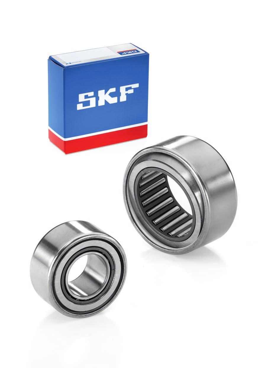
142
143 Alignment needle roller bearings Dimensions Tolerances Internal clearance Misalignment Permissible operating temperature Cages Shaft and housing tolerances Mounting instructions Product tables Alignment needle roller bearings without an inner ring Alignment needle roller bearings with an inner ring
144 Alignment needle roller bearings Alignment needle roller bearings have an outer ring with a convex sphered outside surface. Two polymer seating rings with a concave sphered inside surface that is encased in a drawn sheet steel sleeve are fitted over the outer ring, en abling the bearing to align itself. Alignment needle roller bearings are therefore insensitive to static misalignment of the shaft relative to the housing. SKF supplies alignment needle roller bearings without an inner ring ( fig. 1) and with an inner ring ( fig. 2). Bearings without an inner ring provide the optimum solution for compact arrangements if the shaft can be hardened and ground. In applications where it is not possible or uneconomical to harden and grind the shaft, bearings with an inner ring should be used. Bearings with an inner ring permit axial displace ment of the shaft relative to the housing within certain limits ( product table). If greater axial displacements are anticipated, extended inner rings that are wider than standard inner rings can be used. See chapter Needle roller bearing inner rings, starting on page 196. The bearings are supplied without grease and not sealed. Depending on the application, they can be grease or oil lubricated. The ends of the needle rollers are slightly relieved. The resulting modified line contact between the rollers and raceways means that the load distribution in the bearing is improved. Dimensions Fig. 1 Alignment needle roller bearing without an inner ring RPNA series Fig. 2 Alignment needle roller bearing with an inner ring PNA series The dimensions of alignment needle roller bearings have not been standardized. However, with the exception of bearings with a 52 mm outside diameter, the inner ring bore and outside diameter are standardized, in accordance with ISO 15:1998, as follows: bearings with an outside diameter D 47 mm follow Diameter Series 0 bearings with an outside diameter D 55 mm follow Diameter Series 9 142
145 Tolerances Inner rings, as well as outer rings with a sphered outside surface are manufactured to Normal tolerances in accordance with ISO 492:2002. The tolerance for the width of the external drawn sheet steel sleeve is ± 0,5 mm. Internal clearance Table 1 Shaft and housing tolerance classes Housing Tolerance classes material Housing Shaft inner Shaft bore seat ring seat raceway Steel, cast iron N6 k5 h5 N7 j6 h6 Light alloy R6 k5 h5 R7 j6 h6 SKF alignment needle roller bearings with an inner ring have Normal radial internal clearance as standard. The clearance values are listed in table 7 on page 42 and are in accordance with ISO :2009. They are valid for unmounted bearings under zero measuring load. SKF alignment needle roller bearings without an inner ring have an inside diameter F w that lies within F6 tolerance class when the bearing is unmounted and the rollers are in contact with the outer ring raceway. If the recommended tolerance classes ( table 1) are applied, the oper ational clearance will reach a value in the range of C2 to Normal radial internal clearance ( table 7, page 42). Misalignment 5 Alignment needle roller bearings can compensate static misalignment up to 3 between the shaft and housing. These bearings are unable to accommodate any dynamic misalignment. Permissible operating temperature Due to the polymer seating ring material, the permissible operating temperature range for alignment needle roller bearings is 30 to +100 C. 143
146 Alignment needle roller bearings Cages SKF alignment needle roller bearings are fitted with a machined steel ( fig. 3) or a sheet steel cage ( fig. 4), with adequate free space for lubricant. Machined steel cage Fig. 3 Shaft and housing tolerances Alignment needle roller bearings are mounted with an interference fit in the housing bore. Therefore, shoulders or snap rings are not required to locate the bearing axially so the design of the housing bore is simple and can be produced economically. If the recommended housing bore tolerance classes listed in table 1 on page 143 are applied, alignment movements between the outer ring and the sleeve will be possible. These tolerances, together with the tolerance classes recommended for the inner ring shaft seats or for raceways on the shaft, will reach an operational clearance value in the range of C2 to Normal radial internal clearance ( table 7, page 42). Sheet steel cage Fig
147 Mounting instructions When mounting alignment needle roller bearings, the inner ring should be mounted separately. The outer ring and the polymer seating rings with sleeve and needle roller and cage assembly should be mounted with a mounting dolly ( fig. 5). An O-ring provides a simple means of retaining the bearing on the mounting dolly. The stamped side face should abut the flange of the mounting dolly. Mounting dolly 15 Fig. 5 Note When using grease, the bearing should be lubricated before mounting. Special care should be taken to prevent the sleeve from skewing or tilting when it is being pressed into the housing. Otherwise the rollers and raceways could easily be damaged. D 0,2 0,3 5 F w 0,
148 Alignment needle roller bearings without an inner ring F w mm C r D D 1 F w RPNA Principal Basic load ratings Fatigue Speed ratings Mass Designation dimensions dynamic static load limit Reference Limiting speed speed F w D C C C 0 P u mm kn kn r/min kg ,37 9,15 1, ,032 RPNA 15/ ,8 17,6 2, ,052 RPNA 18/ ,2 19,3 2, ,062 RPNA 20/ , ,11 RPNA 25/ ,5 4, ,11 RPNA 28/ ,9 38 4, ,13 RPNA 30/ ,6 45 5, ,13 RPNA 35/ ,4 51 6, ,14 RPNA 40/ ,5 57 7, ,18 RPNA 45/62 146
149 r a D a Dimensions Abutment and fillet dimensions F w D 1 r D a D a r a min min max max mm mm 15 24,5 1 23,5 24, ,5 1 29,5 30, , ,5 1 37, ,5 1 46,5 47, ,5 1 49,5 50,
150 Alignment needle roller bearings with an inner ring d mm B r s r 1 r 2 D D 1 d F PNA PNA Principal Basic load ratings Fatigue Speed ratings Mass Designation dimensions dynamic static load limit Reference Limiting speed speed d D B C C 0 P u mm kn kn r/min kg ,37 9,15 1, ,037 PNA 12/ ,8 17,6 2, ,062 PNA 15/ ,2 19,3 2, ,073 PNA 17/ , ,14 PNA 20/ ,5 4, ,15 PNA 22/ ,9 38 4, ,16 PNA 25/ ,6 45 5, ,18 PNA 30/ ,4 51 6, ,18 PNA 35/ ,5 57 7, ,23 PNA 40/62 148
151 r a r b D a d a Dimensions Abutment and fillet dimensions d F D 1 r r 1,2 s 1) d a D a D a r a r b min min min min max max max mm mm ,5 1 0,3 0, ,5 24,5 1 0, ,3 0, , ,5 1 0,3 0, ,5 30,5 1 0, ,5 1 0,3 0, , ,5 1 0,3 0, , , ,3 0, , ,5 1 0,3 0, ,5 47,5 1 0, ,5 1 0,3 0, ,5 50,5 1 0, ,3 0, , ) Permissible axial displacement from normal position of one bearing ring in relation to the other 149
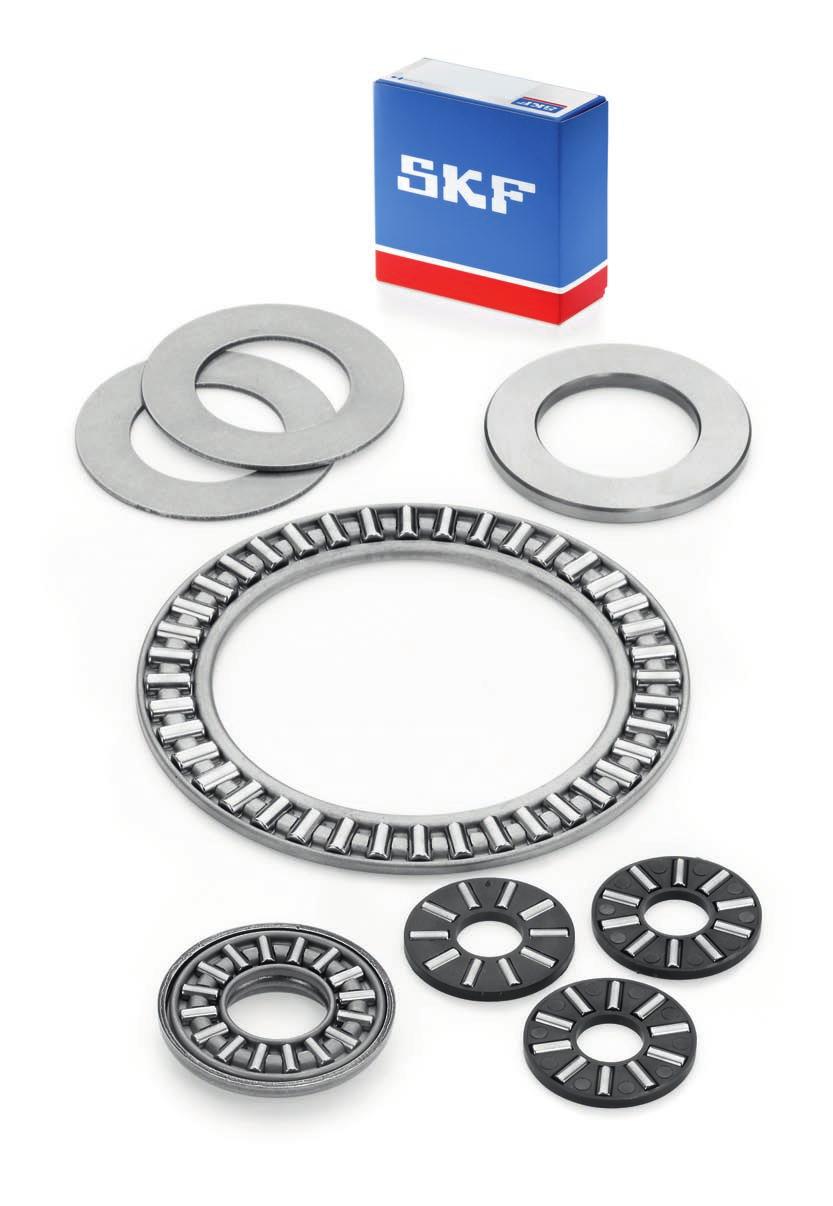
152
153 Needle roller thrust bearings and bearing washers Needle roller and cage thrust assemblies, AXK series Needle roller thrust bearings with a centring spigot, AXW series Bearing washers Dimensions Tolerances Misalignment Cages Design of associated components Raceways on a shaft and in a housing Supplementary designations Product tables Needle roller and cage thrust assemblies and appropriate washers Needle roller thrust bearings with a centring spigot and appropriate washers
154 Needle roller thrust bearings and bearing washers SKF needle roller thrust bearings are fitted with a form-stable cage to reliably guide and retain a large number of needle rollers. The diameter deviations of the rollers within one assembly are within 2 µm, enabling these bearings to accommodate heavy axial loads and shock loads. These bearings provide a high degree of stiffness within a minimum axial space. In applications where the faces of adjacent machine components can serve as raceways, needle roller thrust bearings will take up no more space than a conventional thrust washer. They can accommodate axial loads acting in one direction only. SKF supplies needle roller thrust bearings in two designs: needle roller and cage thrust assemblies, AXK series ( fig. 1) needle roller thrust bearings with a centring spigot, AXW series ( fig. 2) Fig. 1 Needle roller and cage thrust assembly AXK series Fig. 2 Needle roller thrust bearing with a centring spigot For applications where adjacent components cannot serve as raceways, the assemblies can also be combined with washers of various designs. AXW series 152
155 Needle roller and cage thrust assemblies, AXK series Double direction bearing arrangement with internal centring Fig. 3 SKF needle roller and cage thrust assemblies in the AXK series ( fig. 1) range from a 4 to 160 mm bore. If required, washers in the LS, AS, GS 811 or WS 811 series can be used with these assemblies. Double direction bearings A double direction needle roller thrust bearing can be created by combining two needle roller and cage thrust assemblies and bearing washers with an intermediate washer. Depending on the design of the intermediate washer, the bearing has internal centring ( fig. 3) or external centring ( fig. 4). The intermediate washers must have the same surface finish and hardness as the bearing washers. For additional information, refer to the section Design of associated components, starting on page 48. SKF does not supply intermediate washers, but recommendations about suitable dimensions of the washers can be supplied on request. Double direction bearing arrangement with external centring Fig
156 Needle roller thrust bearings and bearing washers Needle roller thrust bearings with a centring spigot, AXW series Needle roller thrust bearing, AXW series, combined with a drawn cup needle roller bearing Fig. 5 SKF needle roller thrust bearings in the AXW series ( fig. 2, page 152) consist of a needle roller and cage thrust assembly and a thrust washer with a centring spigot. The spigot facilitates the mounting process of the thrust bearing and provides an accurate radial centring of the housing washer. Available bore sizes for the thrust assembly range from 10 to 50 mm. Combination with radial needle roller bearings To accommodate combined radial and axial loads, AXW series needle roller thrust bearings can be combined with the following radial needle roller bearings: drawn cup needle roller bearings with a closed end or with open ends ( fig. 5) needle roller bearings with machined rings ( fig. 6) Needle roller thrust bearings, AXW series, combined with a needle roller bearing with machined rings without an inner ring Fig. 6 These arrangements provide an economical and compact solution for combined loads. Bearing washers SKF bearing washers are required in cases where adjacent machine components cannot serve as raceways. Available bore sizes for washers in the LS series range from 6 to 160 mm and in the AS series from 4 to 160 mm. Washers in the LS and AS series can be used as a shaft washer (for AXK or AXW series needle roller thrust assemblies) or housing washer (for AXK series needle roller thrust assemblies). Because of all the possible combinations, the appropriate washers must be ordered separately. with an inner ring Raceway washer Fig. 7 Raceway washers, LS series Raceway washers in the LS series ( fig. 7) are made of carbon chromium (rolling bearing) steel and are hardened. The raceway is ground and the bore and outside diameter are turned. These LS LS series 154
157 washers are used for bearing arrangements where accurate centring of the washers is not necessary or where low speeds are involved. The side face with the smaller chamfers is the raceway, and should face the rollers. Thrust washer Fig. 8 Thrust washers, AS series Thrust washers in the AS series ( fig. 8) are made of spring steel and are 1 mm thick. Both sides of these washers, which are hardened and polished, can be used as raceways. If adjacent machine components are not hardened but have adequate stiffness and the running accuracy requirements are moderate, washers in the AS series can be used to provide a cost-effective bearing arrangement. AS AS series Shaft and housing washers, WS 811 and GS 811 series Shaft washers in the WS 811 series ( fig. 9) and housing washers in the GS 811 series ( fig. 10) are developed primarily for applications with cylindrical roller and cage thrust assemblies, but they can also be combined with needle roller and cage thrust assemblies. These washers, made of carbon chromium bearing steel are hardened and have precision machined raceways. Therefore, SKF recommends using these shaft and housing washers in high-speed applications where ac cur ate centring of the bearing washers is required. WS 811 series shaft washers, which have a ground bore, are available in bore sizes ranging from 15 to 630 mm. When combined with needle roller and cage thrust assemblies, bore sizes up to 160 mm are used. GS 811 series housing washers, which have a ground outside diameter, are available for housing bore diameters ranging from 28 mm to 750 mm. When combined with needle roller and cage thrust assemblies, outside diameter sizes up to 200 mm are used. Shaft washer Housing washer WS WS 811 series Fig. 9 Fig GS GS 811 series 155
158 Needle roller thrust bearings and bearing washers Table 1 Tolerances for needle roller thrust bearings D w B B 1 B B D E b d E a D d D d D d d 1 d D D 1 AXK AXW LS AS WS 811 GS 811 Bearing component Dimensions Tolerance, tolerance class Needle roller and cage thrust assemblies, AXK Bore diameter d E12 Outside diameter D c13 Roller diameter D w Grade 2, ISO 3096:1996 Needle roller thrust bearings with a centring spigot, AXW Bore diameter d E12 Outside diameter D Thickness B 0/ 0,2 mm Roller diameter D w Grade 2, ISO 3096:1996 Raceway washers, LS Bore diameter d E12 Outside diameter D a12 Thickness B h11 Axial runout s i Normal, ISO 199:2005 Thrust washers, AS Bore diameter d E13 Outside diameter D e13 Thickness B 1 ±0,05 mm Shaft washers, WS 811 Bore diameter d Normal, ISO 199:2005 Outside diameter d 1 Thickness B h11 Axial runout s i Normal, ISO 199:2005 Housing washer, GS 811 Outside diameter D Normal, ISO 199:2005 Bore diameter D 1 Thickness B h11 Axial runout s e Normal, ISO 199:
159 Table 2 ISO tolerance classes Nominal a12 c13 e13 h11 E12 E13 dimension Deviations Deviations Deviations Deviations Deviations Deviations over incl. high low high low high low high low high low high low mm μm μm μm μm μm μm Dimensions The dimensions of needle roller and cage thrust assemblies and thrust washers in the AS series are in accordance with ISO 3031:2000. The bore and outside diameters of the other bearing washers are in accordance with ISO 104:2002 for Diameter Series 1 thrust bearings. Tolerances Needle roller and cage thrust assemblies, needle roller thrust bearings with a spigot, and bearing washers are manufactured to the tolerance classes listed in table 1. The values for the dimension deviations of the various ISO tolerance classes mentioned in table 1 are listed in table 2. Misalignment Needle roller thrust bearings cannot tolerate any angular misalignment between the shaft and the housing, or any misalignment between the shaft and the axial support surfaces in the housing. The ends of the needle rollers are relieved slightly to modify the line contact between the raceways and the rollers. This provides favourable load distribution in the bearing and minimizes damaging edge stresses
160 Needle roller thrust bearings and bearing washers Cages SKF needle roller and cage thrust assemblies are fitted as standard with a form-stable, machined steel cage ( fig. 11) or a sheet steel cage ( fig. 12), except for those identified by the designation suffix TN. These assemblies have an injection moulded, glass fibre re inforced, polyamide 66 cage ( fig. 13). The complete range of needle roller thrust bearings with a centring spigot in the AXW series are fitted exclusively with steel cages. Note Assemblies with a polyamide 66 cage can be used at temperatures up to +120 C. The lubricants generally used for rolling bearings do not have a detrimental effect on cage properties. Exceptions are a few synthetic oils and greases with a synthetic oil base and lubricants containing a high proportion of EP additives when used at high temperatures. For bearing arrangements that will operate at continuously high temperatures or under arduous conditions, SKF recommends using needle roller and cage thrust assemblies with a steel cage. For detailed information about the temperature resistance and the applicability of cages, refer to the section Cage materials, starting on page 44. Needle roller and cage thrust assembly with a machined steel cage Needle roller and cage thrust assembly with a sheet steel cage Fig. 11 Fig. 12 Needle roller and cage thrust assembly with a polyamide 66 cage Fig
161 Table 3 Shaft and housing tolerance classes Thrust bearing Series Shaft tolerance class Housing tolerance class component Internal guidance/ External guidance/ centring centring Needle roller and cage thrust assemblies AXK h8 Raceway washers LS h8 radial space radial space H9 Thrust washers AS h8 radial space radial space H9 Shaft washers WS 811 h8 Housing washers GS 811 H9 Design of associated components The support surfaces in the housing and on the shaft must be at right angles to the shaft axis and should provide uninterrupted support for the bearing washers across the entire width of the raceways. When using thrust washers in the AS series, the dimensions E a and E b listed in the product tables should be applied. To provide satisfactory radial guidance for the individual thrust bearing components, suitable tolerance classes for shafts and housings are listed in table 3. Radial space between the shaft and the bore is required for washers that are externally guided in the housing. For washers that are internally guided on the shaft, radial space in the housing bore is required. When SKF needle roller and cage thrust assemblies in the AXW series are combined with drawn cup needle roller bearings or needle roller bearings, the same housing tolerance must be selected for the centring spigot as for the radial bearing. Needle roller and cage thrust assemblies are generally guided radially on the shaft in order to obtain the lowest possible sliding speed against the guiding surfaces. At high speeds, radial guidance must be provided by the shaft and the guiding surface must be ground
162 Needle roller thrust bearings and bearing washers Raceways on a shaft and in a housing For detailed information about suitable materials as well as surface hardness and surface finish, refer to the section Raceways on shafts and in housings, starting on page 50. Raceways machined on the shaft or in the housing should have the same axial runout as is common for shaft or housing washers. The values for the permissible axial runout for the shaft and housing washers of thrust bearings are listed in table 4. Supplementary designations The designation suffixes used to identify certain features of SKF needle roller thrust bearings are explained in the following. TN Injection moulded cage of glass fibre re inforced polyamide
163 Table 4 Normal tolerances for thrust bearings Shaft washer, WS 811 d Δ dmp V dp S 1) i Δ 1) Ts over incl. high low max max high low mm µ μm µ μm µm µm ) Also valid where raceway washers in the LS series are used Housing washer, GS 811 D Δ Dmp V Dp S e over incl. high low max mm µ μm µ μm µm
164 Needle roller and cage thrust assemblies and appropriate washers d 4 80 mm D w D E b d E a AXK Dimensions Basic load ratings Fatigue Speed ratings Mass Designation dynamic static load limit Reference Limiting speed speed d D D w E a E b C C 0 P u mm kn kn r/min g ,15 8,3 0, ,7 AXK 0414 TN ,5 9, ,8 AXK 0515 TN ,3 16 1, AXK 0619 TN ,2 20 2, AXK 0821 TN ,5 26 2, AXK , , AXK ,4 37,5 4, AXK ,5 4, AXK ,5 5, AXK ,4 60 6, AXK AXK ,6 83 9, AXK , AXK , AXK , AXK , , AXK , , AXK AXK , AXK AXK , AXK
165 B 1 B B r 1 45 r 1 r 2 r 1 r 2 D d D d d 1 d D D 1 LS AS WS 811 GS 811 Dimensions Masses Designations Washers Washers Raceway Thrust Shaft Housing LS, AS washer washer washer washer d d 1 D D 1 B r 1,2 WS, min GS mm g AS AS ,75 0,3 6 2 LS 0619 AS ,75 0,3 6 2 LS 0821 AS ,75 0,3 8 3 LS 1024 AS ,75 0,3 9 3 LS 1226 AS ,75 0,3 9 3 LS 1528 AS 1528 WS GS ,75 0, LS 1730 AS 1730 WS GS ,75 0, LS 2035 AS 2035 WS GS ,00 0, LS 2542 AS 2542 WS GS ,00 0, LS 3047 AS 3047 WS GS ,50 0, LS 3552 AS 3552 WS GS ,50 0, LS 4060 AS 4060 WS GS ,00 0, LS 4565 AS 4565 WS GS ,00 0, LS 5070 AS 5070 WS GS ,00 0, LS 5578 AS 5578 WS GS , LS 6085 AS 6085 WS GS , LS 6590 AS 6590 WS GS , LS 7095 AS 7095 WS GS , LS AS WS GS , LS AS WS GS
166 Needle roller and cage thrust assemblies and appropriate washers d mm D w D E b d E a AXK Dimensions Basic load ratings Fatigue Speed ratings Mass Designation dynamic static load limit Reference Limiting speed speed d D D w E a E b C C 0 P u mm kn kn r/min g , AXK , AXK , , AXK , AXK , , AXK AXK , AXK AXK AXK
167 B 1 B B r 1 45 r 1 r 2 r 1 r 2 D d D d d 1 d D D 1 LS AS WS 811 GS 811 Dimensions Masses Designations Washers Washers Raceway Thrust Shaft Housing LS, AS washer washer washer washer d d 1 D D 1 B r 1,2 WS, min GS mm g , LS AS WS GS , LS AS WS GS , LS AS WS GS , LS AS WS GS , LS AS WS GS , LS AS WS GS , LS AS WS GS , LS AS WS GS , LS AS WS GS
168 Needle roller thrust bearings with a centring spigot and appropriate washers d mm B 1 B D D 1 d E a E b AXW Dimensions Basic load ratings Fatigue Speed ratings Mass Designation dynamic static load Reference Limiting limit speed speed d D D 1 B B 1 E a E b C C 0 P u mm kn kn r/min g , ,5 26 2, ,3 AXW , , , ,1 AXW ,2 3, ,4 37,5 4, AXW ,2 3, ,5 4, AXW ,2 3, ,5 5, AXW , ,4 60 6, AXW , AXW , ,6 83 9, AXW , , AXW , , AXW ,2 4, , AXW
169 B 1 B r 1 45 r 1 r 2 D d D d d 1 d LS AS WS 811 Dimensions Masses Designations Washers Washers Raceway washer Thrust washer Shaft washer LS, WS AS d d 1, D B r 1,2 min mm g ,75 0,3 8 3 LS 1024 AS ,75 0,3 9 3 LS 1226 AS ,75 0,3 9 3 LS 1528 AS 1528 WS ,75 0, LS 1730 AS 1730 WS ,75 0, LS 2035 AS 2035 WS ,00 0, LS 2542 AS 2542 WS ,00 0, LS 3047 AS 3047 WS ,50 0, LS 3552 AS 3552 WS ,50 0, LS 4060 AS 4060 WS ,00 0, LS 4565 AS 4565 WS ,00 0, LS 5070 AS 5070 WS
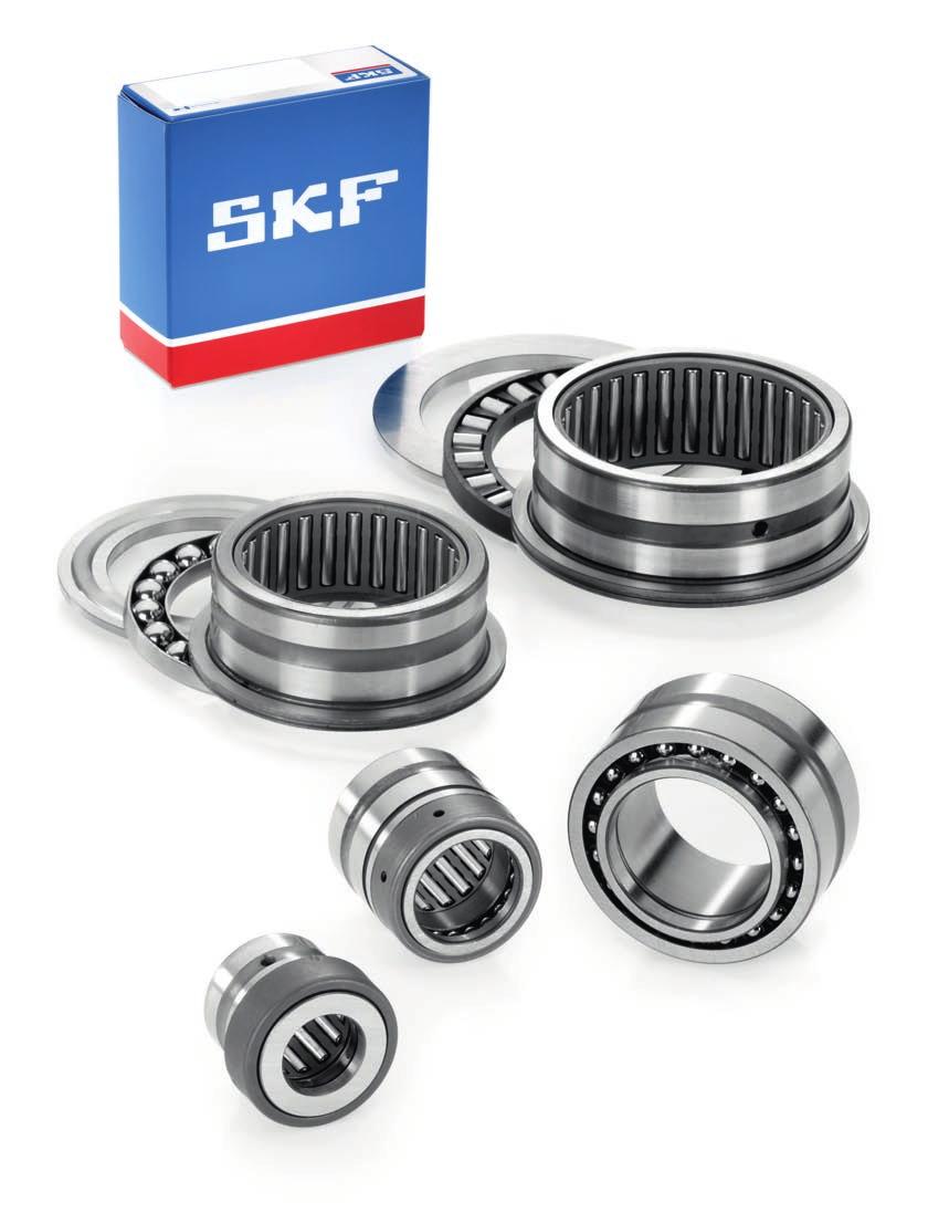
170
171 Combined needle roller bearings Needle roller / angular contact ball bearings Needle roller / angular contact ball bearings, NKIA series Needle roller / angular contact ball bearings, NKIB series Dimensions Tolerances Internal clearance Misalignment Cages Shaft and housing tolerances Lubrication Product tables Needle roller / angular contact ball bearings Needle roller / thrust ball bearings Needle roller / thrust ball bearings, NX series Needle roller / thrust ball bearings, NKX series Dimensions Tolerances Shaft and housing tolerances Internal clearance Misalignment Cages Lubrication Design of associated components Application recommendations Supplementary designations Product tables Needle roller / thrust ball bearings, full complement thrust bearing Needle roller / thrust ball bearings, thrust bearing with a cage Needle roller / cylindrical roller thrust bearings Needle roller / cylindrical roller thrust bearings, NKXR series Needle roller / cylindrical roller thrust bearings, NKXR.. Z series Dimensions Tolerances Shaft and housing tolerances Internal clearance Misalignment Cages Lubrication Design of associated components Application recommendations Supplementary designations Product tables Needle roller / cylindrical roller thrust bearings
172 Needle roller / angular contact ball bearings Combined needle roller bearings consist of a radial needle roller bearing combined with a thrust bearing and are consequently able to accommodate both radial and axial loads. Combined needle roller bearings provide the means to produce locating bearing arrangements where radial space is limited. They are particularly suitable for applications where other types of locating bearings occupy too much space, or where the axial loads are too heavy, the speeds are too high, or the lubricant is inadequate for simple thrust washers. SKF supplies combined needle roller bearings in the following designs: needle roller / angular contact ball bearings needle roller / thrust ball bearings needle roller / cylindrical roller thrust bearings Needle roller / angular contact ball bearings Needle roller / angular contact ball bearings combine a radial needle roller bearing with a radial angular contact ball bearing to produce a low cross section bearing that can operate at high speeds and accommodate heavy radial and light axial loads. The radial loads are accommodated exclusively by the needle roller bearing. SKF supplies these bearings in the following two series: NKIA series ( fig. 1), accommodates axial loads in one direction NKIB series ( fig. 2), accommodates axial loads in both directions Note Bearings of both series are separable. In other words, the inner ring can be mounted separately from the outer ring, roller and cage assemblies. However, the bearings must be kept together as supplied e.g. the outer ring, roller and cage assembly from one bearing are not interchangeable with the the roller and cage assembly from another seemingly identical bearing. Needle roller / angular contact ball bearings, NKIA series SKF needle roller / angular contact ball bearings in the NKIA 59 series ( fig. 1) can accommodate axial loads acting in one direction and can therefore locate the shaft in one direction. For short shafts, where changes in length as a result of thermal expansion are relatively minor, two bearings in the NKIA 59 series can be used in a back-to-back (mirrored) arrangement ( fig. 3). Needle roller / angular contact ball bearings, NKIB series Needle roller / angular contact ball bearings in the NKIB 59 series ( fig. 2) are able to locate Needle roller / angular contact ball bearing Fig. 1 Needle roller / angular contact ball bearing Fig. 2 NKIA 59 series NKIB 59 series 170
173 a shaft in both directions with an axial play between 0,08 and 0,25 mm. To facilitate mounting, the bearing has a two-piece inner ring. When mounting the inner ring, it is important that the two pieces are mounted immediately adjacent to each other without any gap between them. Dimensions The boundary dimensions of bearings in the NKIA 59 series are in accordance with Dimension Series 59 of ISO 15:1998. With the exception of the inner ring width, which is extended on one side, the boundary dimensions of bearings in the NKIB 59 series are in accordance with Dimension Series 59 of ISO 15:1998. Tolerances SKF supplies needle roller / angular contact ball bearings to Normal tolerances in accordance with ISO 492:2002 as standard. The following tolerances in the NKIB 59 series are exceptions: Internal clearance SKF supplies needle roller / angular contact ball bearings with Normal radial internal clearance as standard. The values for radial internal clearance are listed in table 7 on page 42 and are in accordance with ISO :2009. They are valid for unmounted bearings under zero measuring load. Misalignment SKF needle rollers are relieved slightly toward their ends. The modified line contact achieved between the raceways and the needle rollers provides favourable load distribution in the bearing and minimizes damaging edge stresses. It also enables needle roller / angular contact ball bearings to accommodate a minimum amount of misalignment. The detrimental effect of misalignment increases with increasing bearing width and load. Needle roller / angular contact ball bearings are sensitive to misalignment. If misalignment can not be avoided, contact the SKF application engineering service. The bore diameter of the narrow part of the inner ring is slightly larger. The width tolerances of the complete inner ring is 0/ 0,3 mm for all sizes. Fig. 3 NKIA 59 series, back-to-back arrangement 7 171
174 Needle roller / angular contact ball bearings Cages The radial needle roller bearing is fitted as standard with a machined steel cage ( fig. 4) or a sheet steel cage ( fig. 5). The balls of the angular contact ball bearing are retained in an injection moulded cage made of glass fibre re inforced polyamide 66 ( fig. 6). Note Limited by the polyamide 66 cage, needle roller / angular contact ball bearings should not be operated at temperatures above 120 C. The lubricants generally used for rolling bearings do not have a detrimental effect on cage properties. Exceptions are a few synthetic oils and greases with a synthetic oil base and lubricants containing a high proportion of EP additives when used at high temperatures. For detailed information about the temperature resistance and the applicability of cages, refer to the section Cage materials, starting on page 44. Machined steel cage of the radial bearing Sheet steel cage of the radial bearing Fig. 4 Fig. 5 Shaft and housing tolerances For needle roller / angular contact ball bearings SKF recommends machining the shaft seat to a k5 tolerance class, and the housing bore seat to an M6 tolerance class. Tighter fits than those achieved with these tolerance classes should be avoided as they could have a negative influence on bearing performance. In addition to their interference fit on the shaft and in the housing, the bearing rings should be located axially by a shaft shoulder or snap ring. Fig. 6 Polyamide 66 cage of the angular contact ball bearing 172
175 Lubrication To facilitate efficient lubrication, the needle roller bearing has an annular groove with one lubrication hole in the outer ring. Depending on the application, needle roller / angular contact ball bearings can be grease or oil lubricated. In the case of grease lubrication, both the needle roller bearing and ball bearing should be filled with the same lubricant. If grease lubrication is going to be used, the bearing should be lubricated before mounting. Relubrication intervals for the needle roller and angular contact ball bearing must be calculated separately. The lower of the two intervals should be used. For additional information about lubrication, refer to the section Lubrication, starting on page
176 Needle roller / angular contact ball bearings d mm B r 2 r 1 C r 1 r 2 B D F d NKIA NKIB Principal Basic load ratings Fatigue Speed ratings Mass Designation dimensions radial axial load limits Reference Limiting dynamic static dynamic static radial axial speed speed d D B C C C 0 C C 0 P u P u mm kn kn r/min kg , ,07 1,92 1,14 0, ,04 NKIA ,5 16 8, ,07 1,92 1,14 0, ,043 NKIB ,4 15,6 2,27 2,37 1,83 0, ,05 NKIA ,4 15,6 2,27 2,37 1,83 0, ,052 NKIB ,7 17 2,24 2,74 1,96 0, ,056 NKIA ,7 17 2,24 2,74 1,96 0, ,058 NKIB ,6 28 3,79 4,21 3,35 0, ,1 NKIA ,6 28 3,79 4,21 3,35 0, ,11 NKIB ,3 32 4,14 4,93 3,9 0, ,12 NKIA 59/ ,3 32 4,14 4,93 3,9 0, ,12 NKIB 59/ ,2 34,5 4,24 5,26 4,15 0, ,13 NKIA ,2 34,5 4,24 5,26 4,15 0, ,13 NKIB ,5 39 4,54 6,32 4,65 0, ,15 NKIA ,5 39 4,54 6,32 4,65 0, ,15 NKIB ,9 54 5,83 8,42 6,7 0, ,24 NKIA ,9 54 5,83 8,42 6,7 0, ,25 NKIB ,9 71 7,17 10,9 8,8 0, ,32 NKIA ,9 71 7,17 10,9 8,8 0, ,32 NKIB ,7 78 7, ,65 0, ,38 NKIA ,7 78 7, ,65 0, ,38 NKIB ,3 85 7,74 13,7 10,6 0, ,38 NKIA ,3 85 7,74 13,7 10,6 0, ,39 NKIB , ,27 16,7 13,2 0, ,55 NKIA , ,27 16,7 13,2 0, ,56 NKIB , , ,3 0, ,59 NKIA , , ,3 0, ,6 NKIB
177 r a r a d a D a Dimensions Abutment and fillet dimensions d F r 1,2 d a D a r a min min max max mm mm , ,3 16 0, , , ,3 20 0, , , ,3 22 0, , , ,3 25 0, , , ,3 28 0, , , ,3 30 0, , , ,3 35 0, , , ,6 42 0, , , ,6 48 0, , , ,6 52 0, , , ,6 58 0, ,
178 Needle roller / angular contact ball bearings d mm B r 2 r 1 C r 1 r 2 B D F d NKIA NKIB Principal Basic load ratings Fatigue Speed ratings Mass Designation dimensions radial axial load limits Reference Limiting dynamic static dynamic static radial axial speed speed d D B C C C 0 C C 0 P u P u mm kn kn r/min kg , ,96 19,2 14,6 0, ,64 NKIA , ,96 19,2 14,6 0, ,64 NKIB , , ,8 1, ,98 NKIA , , ,8 1, ,99 NKIB
179 r a r a d a D a Dimensions Abutment and fillet dimensions d F r 1,2 d a D a r a min min max max mm mm
180 Needle roller / thrust ball bearings Needle roller / thrust ball bearings Needle roller / thrust ball bearings combine a radial needle roller bearing and a thrust ball bearing. SKF supplies these bearings in the following two series: NX series ( fig. 7), a needle roller bearing with a full complement thrust ball bearing NKX series ( fig. 8), a needle roller bearing with a thrust ball bearing with a cage SKF supplies the bearings in both series without an inner ring. However, for applications where it is not possible to harden and grind the shaft, the needle roller bearing can be combined with an inner ring ( fig. 9). Appropriate inner rings are listed in the product tables and can be ordered separately. Needle roller / thrust ball bearing NX series Needle roller / thrust ball bearing Fig. 7 Fig. 8 NKX series Needle roller / thrust ball bearing, combined with an inner ring Fig. 9 NX series 178
181 Needle roller / thrust ball bearings, NX series SKF needle roller / full complement thrust ball bearings in the NX series are suitable for applications where there are moderate radial loads and lighter, single direction axial loads. Their extremely low sectional height enables shaft centrelines to be positioned close together as is the case for multi-spindle drilling machines. For axial support, the bearings may be mounted against a shoulder or snap ring in the housing bore. The snap ring groove in the outer ring provides a cost-effective and axially spacesaving arrangement ( fig. 10). The appropriate snap rings are listed in the product tables. Needle roller / thrust ball bearings in the NX series have a stamped steel cover that extends over the shaft washer of the thrust ball bearing and is firmly attached to the radial needle roller bearing. These bearings are therefore non-separable. Bearings in the NX series have lubrication holes in the cover ( fig. 11) and are intended for oil lubrication. Bearings in the NX.. Z series ( fig. 12) should be grease lubricated. SKF supplies the thrust ball bearing in this series filled, as standard, with a high-quality grease with good rust inhibiting properties. The cover, which has no lubrication holes, forms a gap-type seal with the shaft washer to retain the grease in the bearing. NX series mounted with a snap ring Needle roller / thrust ball bearing, with lubrication holes in the cover Fig. 10 Fig. 11 NX series Fig. 12 Needle roller / thrust ball bearing, no lubrication holes in the cover 7 NX.. Z series 179
182 Needle roller / thrust ball bearings Needle roller / thrust ball bearings, NKX series SKF needle roller / thrust ball bearings in the NKX series combine a radial needle roller bearing and a thrust ball bearing based on the 511 series. They are able to support single-direction axial loads in addition to radial loads. They also permit relatively high-speed operation. NKX series needle roller / thrust ball bearings ( fig. 13) do not have a cover around the thrust ball bearing. As a result, both the ball and cage assembly and shaft washer can be mounted separately from the rest of the bearing. NKX.. Z series needle roller / thrust ball bearings ( fig. 14) are non-separable. They have a stamped steel cover that extends over the shaft washer of the thrust ball bearing. It is firmly attached to the housing washer that is integral to the needle roller bearing outer ring. The cover makes these bearings non-separable. SKF supplies the thrust ball bearing in this series filled, as standard, with a high-quality grease that has good rust inhibiting properties. The cover, which has no lubrication holes, forms a gap-type seal with the shaft washer to retain the grease in the bearing. Dimensions The boundary dimensions of needle roller / thrust ball bearings in the NKX and NKX.. Z series are in accordance with DIN : The dimensions of bearings in the NX and NX.. Z series are not standardized, but are common in the market. Tolerances SKF needle roller / thrust ball bearings are manu factured to the tolerances and tolerance classes listed in table 1. The radial runout val ues are in accordance with ISO 492:2002 and the Normal axial runout values are in accordance with ISO 199:2005. The values for the devi ations from the nominal diameter of the ISO tolera nce classes F6 and E8 in table 1 are listed in table 2. Shaft and housing tolerances SKF recommends machining the shaft seat to a k5 tolerance class for bearings with or without an inner ring. For the housing bore seat, SKF recommends a K6 tolerance class. For stiff bearing arrangements, SKF recommends an M6 housing bore tolerance class. In addition to their interference fit on the shaft and in the housing, the bearing rings must be axially located by a shoulder or snap ring. Needle roller / thrust ball bearing Fig. 13 Needle roller / thrust ball bearing Fig. 14 NKX series NKX.. Z series 180
183 Internal clearance SKF needle roller / thrust ball bearings combined with the appropriate inner ring, as listed in the product tables, have Normal radial internal clearance as standard. The clearance values are listed in table 7 on page 42 and are in accordance with ISO :2009. They are valid for unmounted bearings under zero measuring load. The radial internal clearance for SKF needle roller / thrust ball bearings without an inner ring depends on the shaft tolerance. If the recommended k5 shaft tolerance class is applied, the tolerance for the inside diameter F w will provide an internal clearance that is slightly less than the Normal radial internal clearance. Needle roller / thrust ball bearing tolerances Dimension 1) Tolerance, tolerance class Table 1 Outside diameter D Normal, ISO 492:1994 Inside diameter of needle roller complement F w F6 Bore diameter d E8 Width C 0/ 0,25 mm Width 2) C 1 0/ 0,20 mm Misalignment SKF needle roller / thrust ball bearings in the NX and NKX series cannot tolerate any angular misalignment between the shaft and the housing or any misalignment between the shaft and the axial support surfaces in the housing. 1) Refer to the illustrations in the product tables, starting on page ) Applicable to bearings in the NKX and NKX.. Z series only ISO tolerance classes Nominal E8 F6 diameter Deviations Deviations over incl. high low high low mm μm μm Table
184 Needle roller / thrust ball bearings Cages The radial needle roller bearing is fitted as standard with a machined steel ( fig. 4, page 172) or a sheet steel cage ( fig. 5, page 172), no designation suffix. However, some small bearings are fitted as standard with an injection moulded cage of glass fibre reinforced polyamide 66 ( fig. 15), designation suffix TN. The cage, that retains the balls of the thrust ball bearing (NKX series), is made of sheet steel ( fig. 16). Polyamide 66 cage of the radial bearing Fig. 15 Note Needle roller / thrust ball bearings with a poly amide 66 cage should not be operated at temperatures above 120 C. The lubricants generally used for rolling bearings do not have a detrimental effect on cage properties. Exceptions are a few synthetic oils and greases with a synthetic oil base and lubricants containing a high proportion of EP additives when used at high temperatures. For bearing arrangements that will operate at continuously high temperatures or under arduous conditions, SKF recommends using needle roller / thrust ball bearings with steel cages. For detailed information about the temperature resistance and the applicability of cages, refer to the section Cage materials, starting on page 44. Fig. 16 Sheet steel cage of the thrust ball bearing, NKX series Lubrication To facilitate efficient lubrication, the needle roller bearing has an annular groove with one lubrication hole in the outer ring. The shielded thrust bearing of needle roller / thrust ball bearings with the designation suffix Z is filled at the factory with a high-quality grease that has good corrosion inhibiting properties. For relubrication, SKF recommends SKF LGWA 2 grease. For additional information about greases, refer to the section Lubrication, starting on page 52. Bearings in the NKX and NX series without the designation suffix Z should be oil lubricated whenever possible, as oil facilitates an adequate supply of lubricant to the bearing. Relubrication intervals for the axial and radial components must be calculated separately. The lower of the two intervals should be used. A calculation is needed for both oil and grease lubrication. 182
185 Design of associated components The diameter of the support surface for the integral housing washer of a needle roller / thrust ball bearing must always be at least 0,5 mm larger than the dimension D 1 or D 2 ( fig. 17) to obtain a clearance fit. The values for the diameters D 1 and D 2 are listed in the product table. Application recommendations SKF needle roller / thrust ball bearings can locate a shaft axially in one direction only. For short shafts, where changes in length as a result of thermal expansion are relatively minor, two bearings can be used in a back-to-back (mirrored) arrangement ( fig. 18). In these cases SKF recommends elastically preloading the thrust ball bearings with cup springs (belle ville washers). This elastic preload helps to avoid skidding of the balls when one of the thrust bearings is unloaded and facilitates proper and quiet performance of the thrust ball bearing. Supplementary designations The designation suffixes used to identify certain features of SKF needle roller / thrust ball bearings are explained in the following. Z Thrust ball bearing with a cover over the outside diameter without lubrication holes. Filled at the factory with a high-quality lithium base NLGI 2 grease. Clearance fit for the integral housing washer Fig. 17 D 1 +0,5 D 2 +0,5 Fig. 18 NKX series, back-to-back arrangement, incorporating belleville washers 7 183
186 Needle roller / thrust ball bearings, full complement thrust bearing F w 7 35 mm C r 1 r 2 C 1 r 2 r 1 d F w D NX NX.. Z Principal Basic load ratings Fatigue Min. Speed ratings Mass Designation dimensions radial axial load limits load Reference Limiting dynamic static dynamic static radial axial factor speed speed F w D C C C 0 C C 0 P u P u A mm kn kn r/min kg ,81 2,75 3,45 5 0,29 0,186 0, ,014 NX 7 TN 1) ,81 2,75 3,45 5 0,29 0,186 0, ,014 NX 7 ZTN 1) ,68 4,15 5,07 8,5 0,475 0,31 0, ,025 NX ,68 4,15 5,07 8,5 0,475 0,31 0, ,025 NX 10 Z ,5 5,4 5,27 9,65 0,61 0,355 0, ,028 NX ,5 5,4 5,27 9,65 0,61 0,355 0, ,028 NX 12 Z ,2 14 6,18 12,2 1,66 0,45 0, ,048 NX ,2 14 6,18 12,2 1,66 0,45 0, ,048 NX 15 Z ,3 16,6 6,37 13,4 1,96 0,5 0, ,053 NX ,3 16,6 6,37 13,4 1,96 0,5 0, ,053 NX 17 Z ,4 19,6 7,8 17,3 2,28 0,64 1, ,068 NX ,4 19,6 7,8 17,3 2,28 0,64 1, ,068 NX 20 Z , ,4 28,5 2,9 1,06 4, ,12 NX , ,4 28,5 2,9 1,06 4, ,12 NX 25 Z , ,7 32,5 4,8 1,2 5, ,13 NX , ,7 32,5 4,8 1,2 5, ,13 NX 30 Z , ,5 38 5,6 1,4 7, ,16 NX , ,5 38 5,6 1,4 7, ,16 NX 35 Z 1) Radial bearing with inserted closure ring 184
187 C a r a r a d a D a B i d i F r a Dimensions Abutment and fillet Appropriate inner ring 2) Appropriate dimensions Dimensions Designation snap ring 3) Designation F w C 1 d r 1,2 d a D a C a r a d i F B i min max max mm mm mm 7 4,7 7 0,3 9, ,3 SW 14 4,7 7 0,3 9, ,3 SW ,7 10 0,3 14, , IR IS1 SW 19 4,7 10 0,3 14, , IR IS1 SW ,7 12 0,3 16, , IR IS1 SW 21 4,7 12 0,3 16, , IR IS1 SW , ,2 0, IR SW , ,2 0, IR SW , ,2 0, IR SW , ,2 0, IR SW , ,2 0, IR SW , ,2 0, IR SW ,3 31, ,2 0, IR IS1 SW ,3 31, ,2 0, IR IS1 SW ,3 36, ,2 0, IR SW ,3 36, ,2 0, IR SW ,3 40, ,2 0, IR SW ,3 40, ,2 0, IR SW ) For additional information, refer to the section Needle roller bearing inner rings, starting on page ) In accordance with DIN 471, not supplied by SKF 185
188 Needle roller / thrust ball bearings, thrust bearing with a cage F w mm C C 1 C 2 r 2 r 1 r 1 r 2 D 1 d 1 d F w D D 2 NKX NKX.. Z Principal Basic load ratings Fatigue Min. Speed ratings Mass Designation dimensions radial axial load limits load Reference Limiting dynamic static dynamic static radial axial factor speed speed F w D C C C 0 C C 0 P u P u A mm kn kn r/min kg ,94 8 9,95 15,3 0,9 0,56 1, ,034 NKX 10 TN 1) ,94 8 9,95 15,3 0,9 0,56 1, ,036 NKX 10 ZTN 1) ,16 8,65 10,4 16,6 0,98 0,62 1, ,038 NKX ,16 8,65 10,4 16,6 0,98 0,62 1, ,04 NKX 12 Z , ,6 18,3 1,66 0,67 1, ,044 NKX , ,6 18,3 1,66 0,67 1, ,047 NKX 15 Z ,3 16,6 10,8 19,6 1,96 0, ,053 NKX ,3 16,6 10,8 19,6 1,96 0, ,055 NKX 17 Z , ,3 27 3,05 1 3, ,083 NKX , ,3 27 3,05 1 3, ,09 NKX 20 Z ,5 19,5 40,5 4 1,5 8, ,13 NKX ,5 19,5 40,5 4 1,5 8, ,13 NKX 25 Z , ,3 45,5 4,8 1, ,14 NKX , ,3 45,5 4,8 1, ,15 NKX 30 Z , ,2 51 5,6 1, ,16 NKX , ,2 51 5,6 1, ,17 NKX 35 Z , ,3 2, ,2 NKX , ,3 2, ,21 NKX 40 Z , ,1 75 7,1 2, ,25 NKX , ,1 75 7,1 2, ,27 NKX 45 Z ,6 81,5 9,65 3, ,28 NKX ,6 81,5 9,65 3, ,3 NKX 50 Z ,8 96,5 41, ,8 4, ,36 NKX ,8 96,5 41, ,8 4, ,38 NKX 60 Z , , ,2 5, ,5 NKX , , ,2 5, ,52 NKX 70 Z 1) Radial bearing with inserted closure ring 186
189 r a d a d b B i d i F r b Dimensions Abutment and fillet dimensions Appropriate inner ring 2) Designation F w C 1 C 2 d d 1 D 1 D 2 r 1,2 d a d b r a r b d i F B i min min max max max mm mm , ,3 19 0,3 0, IR , ,7 25,2 0, ,7 0,3 0, IR , ,3 21 0,3 0, IR , ,7 27,2 0, ,7 0,3 0, IR , ,3 23 0,3 0, IR , ,7 29,2 0, ,7 0,3 0, IR ,3 25 0,3 0, IR ,7 31,1 0, ,7 0,3 0, IR , ,3 29 0,3 0, IR , ,7 36,2 0, ,7 0,3 0, IR , ,6 35 0,6 0, IR , ,7 43,2 0, ,7 0,6 0, IR , ,6 40 0,6 0, IR , ,7 48,2 0, ,7 0,6 0, IR ,6 45 0,6 0, IR ,7 53,2 0, ,7 0,6 0, IR ,6 52 0,6 0, IR ,7 61,2 0, ,7 0,6 0, IR ,6 57 0,6 0, IR ,5 66,5 0, ,5 0,6 0, IR ,6 62 0,6 0, IR ,5 71,5 0, ,5 0,6 0, IR IR ,5 86, , IR IR ,5 96, , IR ) For additional information, refer to the section Needle roller bearing inner rings, starting on page
190 Needle roller / cylindrical roller thrust bearings Needle roller / cylindrical roller thrust bearings Needle roller / cylindrical roller thrust bearings combine a radial needle roller bearing and a cylindrical roller thrust bearing based on the 811 series. SKF supplies these bearings in the following two series: NKXR series ( fig. 19), cylindrical roller thrust bearing is separable NKXR.. Z series ( fig. 20), non-separable bearing These bearings are supplied without an inner ring. For applications where it is not possible to harden and grind the shaft, the bearings can be combined with an inner ring ( fig. 21). Appropriate inner rings are listed in the product tables and can be ordered separately. Needle roller / cylindrical roller thrust bearing NKXR series Needle roller / cylindrical roller thrust bearing Fig. 19 Fig. 20 Needle roller / cylindrical roller thrust bearings, NKXR series SKF needle roller / cylindrical roller thrust bearings in the NKXR series ( fig. 19) are separable. Both the cylindrical roller and cage thrust assembly and shaft washer can be mounted separately from the rest of the bearing. Needle roller / cylindrical roller thrust bearings, NKXR.. Z series SKF needle roller / cylindrical roller thrust bearings in the NKXR.. Z series ( fig. 20) are nonseparable. They have a stamped steel cover that extends over the shaft washer of the cylindrical roller thrust bearing. It is firmly attached to the housing washer that is integral to the needle roller bearing outer ring. The cover makes these bearings non-separable. SKF supplies the cylindrical roller thrust bearing in this series filled, as standard, with a high-quality grease that has good rust inhibiting properties. The cover, which has no lubrication holes, forms a gap-type seal with the shaft washer to retain the grease in the bearing. NKXR.. Z series Needle roller / cylindrical roller thrust bearing, NKXR.. Z series, combined with an inner ring Fig
191 Dimensions The boundary dimensions of the single direction needle roller / cylindrical roller thrust bearings are in accordance with DIN : In addition to their interference fit on the shaft and in the housing, the bearing rings must be axially located by a shaft shoulder or locating ring. Tolerances SKF needle roller / cylindrical roller thrust bearings are manufactured to the tolerances and tolerance classes listed in table 3. The radial runout values are in accordance with ISO 492:2002 and the axial runout values are in accordance with Normal tolerance class of ISO 199:2005. The values for the deviations from the nominal diameter of the ISO tolerance classes F6 and E8 in table 3 are listed in table 4. Shaft and housing tolerances SKF recommends machining the shaft seat for needle roller / cylindrical roller thrust bearings to a k5 tolerance class for bearings with or without an inner ring. For the housing bore seat, SKF recommends a K6 tolerance class. For stiff bearing arrangements, SKF recommends an M6 housing bore tolerance class. Internal clearance SKF needle roller / cylindrical roller thrust bearings combined with the appropriate inner ring, as listed in the product tables, have Normal radial internal clearance as standard. The clearance values are listed in table 7 on page 42 and are in accordance with ISO :2009. They are valid for unmounted bearings under zero measuring load. The radial internal clearance for SKF needle roller / cylindrical roller thrust bearings without an inner ring depends on the shaft tolerance. If the recommended k5 shaft tolerance class is applied, the tolerance for the inside diameter F w will provide an internal clearance that is slightly less than the Normal radial internal clearance. Table 3 Needle roller / cylindrical roller thrust bearing tolerances Dimension 1) Tolerance, tolerance class Outside diameter D Normal, ISO 492:1994 Inside diameter of needle roller complement F w F6 Bore diameter d E8 Width C 0/ 0,25 mm Width C 1 0/ 0,20 mm ISO tolerance classes Nominal E8 F6 diameter Deviations Deviations over incl. high low high low mm μm μm Table 4 7 1) Refer to the illustrations in the product table on page
192 Needle roller / cylindrical roller thrust bearings Misalignment Needle roller / cylindrical roller thrust bearings cannot accommodate any angular misalignment of the shaft relative to the housing, or between the axial support surfaces on the shaft or in the housing. Cages The radial needle roller bearing is fitted as standard with a machined steel cage ( fig. 4, page 172) or a sheet steel cage ( fig. 5, page 172). The cage that retains the rollers of the cylindrical roller thrust bearing is made of glass fibre reinforced polyamide 66 ( fig. 22). Note Needle roller / cylindrical roller thrust bearings should not be operated at temperatures above 120 C. The lubricants generally used for rolling bearings do not have a detrimental effect on cage properties. Exceptions are a few synthetic oils and greases with a synthetic oil base and lubricants containing a high proportion of EP additives when used at high temperatures. For detailed information about the temperature resistance and the applicability of cages, refer to the section Cage materials, starting on page 44. Lubrication To promote efficient lubrication, SKF needle roller / cylindrical roller thrust bearings have an annular groove with lubrication holes in the outer ring of the needle roller bearing. The shielded thrust bearing of needle roller / cylindrical roller thrust bearings, in the NKXR.. Z series, is filled at the factory with a high-quality grease with good corrosion inhibiting properties. SKF recommends SKF LGWA 2 grease for relubrication. For additional information about greases, refer to the section Lubrication, starting on page 52. Bearings in the NKXR series, without the designation suffix Z, should be oil lubricated whenever possible, as oil facilitates an adequate supply of lubricant to the bearing. Relubrication intervals for the needle roller bearing and cylindrical roller thrust bearing must be calculated separately. The lower of the two intervals should be used. A calculation is necessary for both oil and grease lubrication. Fig. 22 Polyamide 66 cage of the cylindrical roller thrust bearing 190
193 Design of associated components The diameter of the support surface for the integral housing washer of needle roller / cylindrical roller thrust bearings must always be at least 0,5 mm larger than the dimension D 1 or D 2 ( fig. 23) to obtain a clearance fit. The values for the diameters D 1 and D 2 are listed in the product table. Application recommendations SKF needle roller / cylindrical roller thrust bearings can locate a shaft axially in one direction. For short shafts, where changes in length as a result of thermal expansion are relatively minor, two bearings can be used in a back-toback (mirrored) arrangement ( fig. 24). In these cases, SKF recommends elastically preloading the cylindrical roller thrust bearings with cup springs (belleville washers). This elastic preload helps to avoid skidding of the rolling elements when one of the thrust bearings is unloaded. Elastic preload also reduces the noise level of the cylindrical roller thrust bearing. Supplementary designations The designation suffixes used to identify certain features of SKF needle roller / cylindrical roller thrust bearings are explained in the following. Z Cylindrical roller thrust bearing with a cover over the outside diameter without lubrication holes. Filled at the factory with a high-quality lithium base NLGI 2 grease. Clearance fit for the integral housing washer Fig. 23 D 1 +0,5 D 2 +0,5 Fig. 24 NKXR series, back-to-back arrangement 7 191
194 Needle roller / cylindrical roller thrust bearings F w mm C C 1 C 2 r 2 r 1 r 1 r 2 D 1 d F w D D 2 NKXR NKXR.. Z Principal Basic load ratings Fatigue Min. Speed ratings Mass Designation dimensions radial axial load limits load Reference Limiting dynamic static dynamic static radial axial factor speed speed F w D C C C 0 C C 0 P u P u A mm kn kn r/min kg , ,2 27 1,66 2,45 0, ,042 NKXR , ,2 27 1,66 2,45 0, ,045 NKXR 15 Z ,3 16,6 12,2 31,5 1,96 2,85 0, ,05 NKXR ,3 16,6 12,2 31,5 1,96 2,85 0, ,053 NKXR 17 Z , ,6 48 3,05 4,65 0, ,08 NKXR , ,6 48 3,05 4,65 0, ,084 NKXR 20 Z , ,5 4 6,8 0, ,12 NKXR , ,5 4 6,8 0, ,13 NKXR 25 Z , ,8 7,65 0, ,14 NKXR , ,8 7,65 0, ,14 NKXR 30 Z , ,6 9,15 0, ,16 NKXR , ,6 9,15 0, ,17 NKXR 35 Z , ,3 13,7 1, ,2 NKXR , ,3 13,7 1, ,21 NKXR 40 Z , ,1 15,3 1, ,24 NKXR , ,1 15,3 1, ,26 NKXR 45 Z , ,65 16,6 2, ,27 NKXR , ,65 16,6 2, ,29 NKXR 50 Z 192
195 r a d a B i d i F r b Dimensions Abutment and fillet dimensions Appropriate inner ring 1) Designation F w C 1 C 2 d D 1 D 2 r 1,2 d a r a r b d i F B i min max max mm mm , ,3 23,7 0,3 0, IR , ,2 0,3 23,7 0,3 0, IR ,3 25,7 0,3 0, IR ,2 0,3 25,7 0,3 0, IR , ,3 30,7 0,3 0, IR , ,2 0,3 30,7 0,3 0, IR , ,6 37,7 0,6 0, IR , ,2 0,6 37,7 0,6 0, IR , ,6 42,7 0,6 0, IR , ,2 0,6 42,7 0,6 0, IR ,6 47,7 0,6 0, IR ,2 0,6 47,7 0,6 0, IR ,6 55,7 0,6 0, IR ,2 0,6 55,7 0,6 0, IR ,6 60,6 0,6 0, IR ,5 0,6 60,6 0,6 0, IR ,6 65,6 0,6 0, IR ,5 0,6 65,6 0,6 0, IR ) For additional information, refer to the section Needle roller bearing inner rings, starting on page
196
197 Needle roller bearing components Needle roller bearing inner rings Inner rings in the IR series Tolerances Internal clearance Raceways with a machining allowance Inner rings in the LR series Tolerances Inner ring seats Shaft diameter tolerances Cylindricity Runout Supplementary designations Product tables Needle roller bearing inner rings Needle rollers Materials Tolerances Supplementary designations Product tables Needle rollers Radial shaft seals with a low cross sectional height G design radial shaft seals SD design radial shaft seals Design of associated components Speeds Operating temperature range Mounting instructions Product tables Radial shaft seals with a low cross sectional height
198 Needle roller bearing inner rings Needle roller bearing inner rings SKF supplies inner rings for needle roller bearings separately. They are primarily used in conjunction with needle roller and cage assemblies and drawn cup needle roller bearings in applications where the shaft cannot be ground and hardened to a suitable raceway tolerance. Extended inner rings are also available. These permit greater axial displacement of the shaft, relative to the housing, compared to standard width inner rings. They also provide an excellent counterface for the lips of contact seals. SKF supplies needle roller bearing inner rings in the following two series: inner rings in the IR series ( fig. 1), with or without a lubrication hole, with or without machining allowance inner rings in the LR series ( fig. 2). Regardless of whether the ring has an interference or loose fit, it should be located to the shaft by either a shoulder or snap ring to prevent axial movements. Inner ring Inner ring IR series Fig. 1 Fig. 2 Inner rings in the IR series Inner rings in the IR series ( fig. 1) are the standard SKF inner rings for needle roller bearings. They are made of carbon chromium bearing steel that has been hardened and ground. The raceway surface, which is precision machined, has a lead-in chamfer on both sides to simplify assembly. The chamfer also protects the sealing lips from damage during the mounting process. Some sizes of IR inner rings have a lubrication hole ( fig. 3). These inner rings are identified by the designation suffix IS1. Inner rings with additional lubrication holes are available on request. Tolerances The bore diameter and the width of IR inner rings are made to Normal tolerances in accordance with ISO 492:2002. LR series Inner ring, with a lubrication hole Fig. 3 IR.. IS1 series 196
199 Internal clearance If the recommended shaft and housing tolerance classes are applied, the tolerances for the inner ring raceway diameter F will provide applications with the following internal clearance: a suitable (medium) operational clearance that will reach a value in the range of C2 to C3 radial internal clearance, when combined with SKF drawn cup needle roller bearings. The clearance value depends on the raceway diameter and the operating temperature. a Normal radial internal clearance, when combined with SKF needle roller bearings with a machined outer ring. The clearance values are listed in table 7 on page 42 and are in accordance with ISO :2009. They are valid for unmounted bearings under zero measuring load. Raceways with a machining allowance On request, SKF can supply inner rings in the IR series with a pre-ground raceway and a machining allowance z. These inner rings are identified by the designation suffix VGS. The machining allowance depends on the inner ring raceway diameter and is listed in table 1. Table 1 Inner ring raceway diameter Raceway Machining Preground diameter allowance raceway F z diameter F VGS over incl. mm mm mm 50 0, , ,20 F VGS = F + z h7 tolerance class , , , ,40 Fig. 4 Inner ring, LR series, combined with a needle roller and cage assembly Inner rings in the LR series Inner rings in the LR series ( fig. 2, page 196) are made of carbon chromium bearing steel and have been hardened. The bore and outside diameter are ground. The side faces are turned and the edges are smoothed. Therefore, they have larger tolerances than inner rings in the IR series. For applications where the larger run-out and width tolerances are less important, these inner rings can be used to provide a cost-effective bearing arrangement. They are, therefore, often combined with drawn cup needle roller bearings or needle roller and cage assemblies ( fig. 4)
200 Needle roller bearing inner rings Tolerances SKF inner rings in the LR series are manufactured to the following tolerance classes: raceway diameter to h6 tolerance class width to h12 tolerance class bore diameter to K6 tolerance class. The values for the deviation from the nominal dimension for these tolerances are provided in table 2. Inner ring seats The seat for an inner ring mounted on a shaft should be in accordance with the following recommendations. Table 2 ISO tolerance classes for LR series inner rings Nominal h6 h12 K6 diameter Deviations Deviations Deviations over incl. high low high low high low mm μm μm μm Shaft diameter tolerances When inner rings are used under conditions of point load and mounted with a loose fit, the seat should be machined to h6 or g6 tolerance class. When the load rotates, the inner rings should have an interference fit. Sufficient interference can be obtained if the recommended shaft tolerance classes ( table 3, page 105) are applied. Cylindricity The cylindricity of an inner ring seat should be in accordance with ISO 1101:2004, corresponding to the following IT tolerance classes: IT5/2 for inner rings under point load IT4/2 for inner rings under rotating load. Runout Inner ring shaft abutments should have a runout corresponding to IT4 tolerance class. 198
201 Supplementary designations The designation suffixes used to identify certain features of SKF needle roller bearing inner rings are explained in the following. EGS Inner ring with non-directionally ground raceway IS.. Needle roller bearing with one or more lubricating holes in the inner ring, a figure following indicates the number of holes ISR.. Needle roller bearing with an annular groove and one or more lubricating holes in the inner ring, a figure following indicates the number of holes VGS Inner ring with a pre-ground raceway and a machining allowance C2 Bearing internal clearance smaller than Normal C3 Bearing internal clearance greater than Normal C4 Bearing internal clearance greater than C
202 Needle roller bearing inner rings d 5 42 mm r 1 r2 B 30 r F d IR IR.. IS1 LR Dimensions Mass Designation Dimensions Mass Designation d F B r, r 1,2 d F B r, r 1,2 mm kg ,3 0,0028 IR ,3 0,0038 IR ,3 0,0032 IR ,3 0,0043 IR ,3 0,0037 IR IS ,5 0,3 0,0031 IR ,5 0,3 0,0031 LR ,3 0,0036 IR ,3 0,0049 IR ,3 0,0048 IR IS ,5 0,3 0,005 IR ,5 0,3 0,005 LR ,5 0,3 0,0059 IR ,5 0,3 0,0059 LR ,3 0,0045 IR ,3 0,0061 IR ,5 0,3 0,0052 IR ,5 0,3 0,0052 LR ,3 0,0073 IR IS ,3 0,0074 IR ,3 0,0092 IR ,3 0,012 IR ,3 0,0058 IR ,5 0,3 0,0061 IR ,5 0,3 0,0061 LR ,3 0,008 IR ,5 0,3 0,0081 IR ,5 0,3 0,0081 LR ,5 0,3 0,011 IR ,5 0,3 0,011 LR ,3 0,0079 IR IS ,3 0,0087 IR ,3 0,011 IR ,3 0,014 IR ,3 0,015 IR mm kg ,3 0,01 IR ,5 0,3 0,0072 LR ,3 0,0096 IR ,5 0,3 0,0099 IR ,5 0,3 0,0099 LR ,3 0,013 IR ,3 0,016 IR ,3 0,012 IR IS ,3 0,014 IR ,3 0,024 IR ,3 0,011 IR ,5 0,3 0,011 IR ,5 0,3 0,011 LR ,3 0,014 IR ,5 0,3 0,014 IR ,5 0,3 0,014 LR ,5 0,3 0,021 IR ,5 0,3 0,021 LR ,3 0,014 IR ,3 0,018 IR ,3 0,015 IR ,3 0,019 IR ,3 0,027 IR ,3 0,034 IR ,3 0,017 IR ,3 0,021 IR ,5 0,3 0,016 LR ,3 0,021 IR IS ,5 0,3 0,022 LR ,3 0,022 IR ,3 0,028 IR ,5 0,3 0,028 IR ,5 0,3 0,028 LR ,5 0,3 0,036 IR ,5 0,3 0,036 LR ,3 0,041 IR ,5 0,3 0,053 IR ,5 0,3 0,053 LR ,6 0,045 IR
203 Dimensions Mass Designation Dimensions Mass Designation d F B r, r 1,2 d F B r, r 1,2 mm kg mm kg ,3 0,018 IR ,3 0,023 IR ,3 0,03 IR ,3 0,035 IR ,5 0,3 0,036 IR ,5 0,3 0,036 LR ,3 0,054 IR ,3 0,026 IR ,3 0,039 IR ,5 0,3 0,02 LR ,3 0,026 IR IS ,5 0,3 0,027 LR ,3 0,028 IR ,3 0,033 IR ,5 0,3 0,034 IR ,5 0,3 0,034 LR ,5 0,3 0,043 IR ,5 0,3 0,043 LR ,3 0,05 IR ,3 0,053 IR ,5 0,3 0,064 IR ,5 0,3 0,064 LR ,6 0,052 IR ,3 0,025 IR ,3 0,028 IR ,3 0,044 IR ,5 0,3 0,023 LR ,3 0,025 IR ,3 0,031 IR ,5 0,3 0,031 LR ,3 0,032 IR ,3 0,04 IR ,5 0,3 0,041 IR ,5 0,3 0,041 LR ,3 0,05 IR ,3 0,059 IR ,6 0,05 IR ,6 0,061 IR ,6 0,065 IR IS ,3 0,042 IR ,3 0,063 IR ,6 0,068 IR ,6 0,12 IR ,3 0,022 IR ,5 0,3 0,027 LR ,5 0,3 0,037 LR ,3 0,038 IR ,3 0,044 IR ,5 0,3 0,046 IR ,5 0,3 0,046 LR ,3 0,068 IR ,6 0,064 IR IS ,6 0,12 IR ,6 0,082 IR ,3 0,048 IR ,3 0,074 IR ,5 0,3 0,041 LR ,3 0,043 IR ,3 0,051 IR ,5 0,3 0,053 IR ,5 0,3 0,053 LR ,3 0,077 IR ,6 0,092 IR ,6 0,17 IR ,11 IR IS ,12 IR ,3 0,054 IR ,3 0,081 IR
204 Needle roller bearing inner rings d mm r 1 r2 B 30 r F d IR IR.. IS1 LR Dimensions Mass Designation Dimensions Mass Designation d F B r, r 1,2 d F B r, r 1,2 mm kg ,5 0,3 0,058 LR ,6 0,071 IR ,5 0,3 0,074 IR ,5 0,3 0,074 LR ,6 0,1 IR ,6 0,089 IR ,6 0,16 IR ,12 IR IS ,13 IR ,6 0,063 IR IS ,5 0,6 0,064 LR ,6 0,078 IR ,6 0,11 IR ,6 0,12 IR ,6 0,21 IR ,13 IR IS ,16 IR ,18 IR ,6 0,086 IR ,6 0,12 IR ,14 IR ,26 IR ,1 0,2 IR ,15 IR ,6 0,21 IR ,28 IR ,2 IR ,1 0,22 IR ,14 IR ,26 IR ,16 IR ,23 IR ,1 0,23 IR ,22 IR ,27 IR ,31 IR ,49 IR mm kg ,24 IR ,29 IR ,34 IR ,52 IR ,25 IR ,3 IR ,36 IR ,55 IR ,28 IR ,39 IR ,1 0,58 IR ,1 1,05 IR ,29 IR ,34 IR ,41 IR ,1 0,61 IR ,1 1,1 IR ,31 IR ,43 IR ,1 0,64 IR ,1 1,15 IR ,1 0,37 IR ,1 0,51 IR ,1 0,78 IR ,41 IR ,1 0,84 IR ,44 IR ,1 1 IR ,1 0,86 IR ,5 1,7 IR ,1 0,92 IR ,5 1,8 IR
205 Dimensions Mass Designation d F B r, r 1,2 mm kg ,1 1,1 IR ,1 1,2 IR ,1 1,45 IR ,1 1,5 IR ,5 2,4 IR ,5 2,5 IR ,5 2,75 IR ,6 IR IR ,1 IR ,1 9,2 IR ,1 9,8 IR ,1 10 IR ,1 11 IR ,1 17 IR
206 Needle rollers Needle rollers Needle rollers can be used to make full complement bearing arrangements for slow speed or oscillating applications. These compact bearing arrangements have a high load carrying capacity and are economical, provided the shaft and housing bore can serve as raceways. The cylindrical surface of the rollers is slightly relieved toward the roller ends to prevent damaging edge stresses. For additional information about surface requirements for raceways, refer to the section Raceways on shafts and in housings, starting on page 50. For assistance in designing full complement bearing arrangements or to calculate performance data for these bearing arrangements, contact the SKF application engineering service. The rollers are gauged according to their minimum and maximum deviation from the nom inal diameter. Needle rollers for each gauge are packed separ ately and the package is marked with the gauge limits, e.g. N/M2 or M2/M4, where M signifies minus and N zero. For a needle roller with a 2 mm nominal diameter and gauge limits M2/M4, the actual diameter is between 1,998 mm and 1,996 mm. Note Needle rollers of the same gauge should be used in each bearing arrangement. A delivery of needle rollers of the same nominal diameter may contain packages of one or more gauges, depending on availability at the time. Materials SKF needle rollers are made from carbon chromium steel with a hardness of 58 to 65 HRC and have a precision machined surface. Tolerances SKF needle rollers are in accordance with ISO 3096:1996 Grade 2 for flat end needle rollers. SKF supplies needle rollers with the dimensional and form tolerances as listed in table 3, where the preferred diameter deviations range from 0 to 7 µm. Table 3 Dimensional and form accuracy of SKF needle rollers, grade G2 Diameter D w Length L w Deviation Gauge Gauge Roundness Tolerance class tolerance limits (max circularity high low deviation in accordance with ISO 3096) µm / 2 1 h13 1/ 3 2/ 4 3/ 5 4/ 6 5/ 7 6/ 8 7/ 9 8/
207 Supplementary designations The designation suffixes used to identify certain features of SKF needle rollers are explained in the following. BF G2 Needle roller with flat ends Needle roller in accordance with ISO 3096:1996 Grade 2 M../M.. Diameter tolerance of needle rollers, e.g. M2/M4 indicates diameter tolerance 2 to 4 µm N/M.. Diameter tolerance of needle rollers, e.g. N/M2 indicates diameter tolerance 0 to 2 µm 8 205
208 Needle rollers D w 1 6 mm L w D w r 1 min r 1 max r 2 min r 2 max Dimensions Mass Designation per 1000 D w L w r 1,2 r 1 r 2 min max max mm kg 1 7,8 0,1 0,4 0,6 0,048 RN BF/G2 1,5 5,8 0,1 0,4 0,6 0,081 RN BF/G2 6,8 0,1 0,4 0,6 0,094 RN BF/G2 7,8 0,1 0,4 0,6 0,108 RN BF/G2 9,8 0,1 0,4 0,6 0,136 RN BF/G2 11,8 0,1 0,4 0,6 0,164 RN BF/G2 13,8 0,1 0,4 0,6 0,191 RN BF/G2 2 6,3 0,2 0,6 0,8 0,16 RN BF/G2 7,8 0,2 0,6 0,8 0,19 RN BF/G2 9,8 0,2 0,6 0,8 0,24 RN BF/G2 11,8 0,2 0,6 0,8 0,29 RN BF/G2 13,8 0,2 0,6 0,8 0,34 RN BF/G2 15,8 0,2 0,6 0,8 0,39 RN BF/G2 17,8 0,2 0,6 0,8 0,44 RN BF/G2 19,8 0,2 0,6 0,8 0,49 RN BF/G2 21,8 0,2 0,6 0,8 0,54 RN BF/G2 2,5 7,8 0,2 0,6 0,8 0,3 RN BF/G2 9,8 0,2 0,6 0,8 0,38 RN BF/G2 11,8 0,2 0,6 0,8 0,45 RN BF/G2 13,8 0,2 0,6 0,8 0,53 RN BF/G2 15,8 0,2 0,6 0,8 0,61 RN BF/G2 17,8 0,2 0,6 0,8 0,69 RN BF/G2 19,8 0,2 0,6 0,8 0,76 RN BF/G2 21,8 0,2 0,6 0,8 0,84 RN BF/G2 23,8 0,2 0,6 0,8 0,92 RN BF/G2 3 9,8 0,2 0,6 0,8 0,54 RN BF/G2 11,8 0,2 0,6 0,8 0,65 RN BF/G2 13,8 0,2 0,6 0,8 0,77 RN BF/G2 15,8 0,2 0,6 0,8 0,88 RN BF/G2 17,8 0,2 0,6 0,8 0,99 RN BF/G2 19,8 0,2 0,6 0,8 1,1 RN BF/G2 21,8 0,2 0,6 0,8 1,21 RN BF/G2 23,8 0,2 0,6 0,8 1,32 RN BF/G2 206
209 Dimensions Mass Designation per 1000 D w L w r 1,2 r 1 r 2 min max max mm kg 3,5 11,8 0,3 0,8 1 0,89 RN BF/G2 13,8 0,3 0,8 1 1,04 RN BF/G2 15,8 0,3 0,8 1 1,19 RN BF/G2 17,8 0,3 0,8 1 1,34 RN BF/G2 19,8 0,3 0,8 1 1,5 RN BF/G2 21,8 0,3 0,8 1 1,65 RN BF/G2 29,8 0,3 0,8 1 2,25 RN BF/G2 34,8 0,3 0,8 1 2,63 RN BF/G2 4 11,8 0,3 0,8 1 1,16 RN BF/G2 13,8 0,3 0,8 1 1,36 RN BF/G2 15,8 0,3 0,8 1 1,56 RN BF/G2 17,8 0,3 0,8 1 1,76 RN BF/G2 19,8 0,3 0,8 1 1,95 RN BF/G2 21,8 0,3 0,8 1 2,15 RN BF/G2 23,8 0,3 0,8 1 2,35 RN BF/G2 25,8 0,3 0,8 1 2,55 RN BF/G2 27,8 0,3 0,8 1 2,74 RN BF/G2 29,8 0,3 0,8 1 2,94 RN BF/G2 34,8 0,3 0,8 1 3,43 RN BF/G2 39,8 0,3 0,8 1 3,93 RN BF/G2 5 15,8 0,3 0,8 1 2,44 RN BF/G2 19,8 0,3 0,8 1 3,05 RN BF/G2 21,8 0,3 0,8 1 3,36 RN BF/G2 23,8 0,3 0,8 1 3,67 RN BF/G2 25,8 0,3 0,8 1 3,98 RN BF/G2 27,8 0,3 0,8 1 4,28 RN BF/G2 29,8 0,3 0,8 1 4,59 RN BF/G2 34,8 0,3 0,8 1 5,36 RN BF/G2 39,8 0,3 0,8 1 6,13 RN BF/G ,8 0,3 0,8 1 3,95 RN BF/G2 207
210 Radial shaft seals with a low cross sectional height Radial shaft seals with a low cross sectional height It is not always easy to find commercially available radial shaft seals for bearing arrangements that incorporate needle roller bearings because of their very low cross section. As a result, SKF offers a wide assortment of special low cross section radial shaft seals to fit virtually all of these bearing arrangements. These contact seals are designed without garter springs and available in two designs: Radial shaft seal Fig. 5 the G design with a single lip the SD design with a double lip G design radial shaft seals G design radial shaft seals are made of acrylonitrile-butadiene rubber (NBR). The seals for shaft diameters 8 mm ( fig. 5) are reinforced with sheet steel. The rubber outside diameter enhances the seal around the housing bore and reduces the risk of damage to the seal and housing during installation and removal. To attain an adequate degree of rigidity for seals for shaft diameters 7 mm ( fig. 6), the rubber material is metal cased. These seals are identified by the designation suffix S. If the seal is to be used primarily for lubricant retention, it should be mounted with the lip facing inward. If the primary purpose of the seal is to exclude contaminants, the lip should face outward, away from the bearing ( fig. 7). For information about the chemical resistance of acrylonitrile-butadiene rubber (NBR), refer to the SKF Interactive Engineering Catalogue (section Chemical resistance). Radial shaft seal G series (d 1 8 mm) G.. S series (d 1 7 mm) Needle roller bearing with machined rings with an external G design seal Fig. 6 Fig. 7 SD design radial shaft seals SD design radial shaft seals ( fig. 8) have a primary seal lip and an auxiliary dust lip. The lips are made of polyurethane (AU) and the reinforcement ring is made of polyamide (PA) instead of metal. The auxiliary lip is the smaller of the two lips and designed with zero lip/shaft interference to avoid additional friction, heat and energy losses. The primary seal lip, i.e. the larger of the two lips, is a contact seal and should always point toward the medium that is to be sealed. Therefore, if the primarily function is protection Primary lip facing inward Primary lip facing outward 208
211 against ingress of contaminants, the primary lip should face outward. The auxiliary lip will contribute to retain lubricant in the bearing arrangement. In applications whereas the main purpose is retaining the lubricant, the primary lip should face inward, toward the bearing. The cavity between the two lips should be filled with a grease that is compatible with the lubricant used in the application. This will provide additional protection and prevent the seal from dry running. SD seals are resistant to lubricating oils, even those containing small quantities of EP additives, and also to mineral oil based greases. Depending on the counterface of the shaft, SD seals can also be used as wiper seals for linear applications with speeds up to 3 m/s. Design of associated components Shaft requirements To achieve a reliable seal and sufficiently long service life, the surface of the seal counterface should have a hardness of at least 55 HRC or 600 HV. The surface roughness of the counterface on the shaft of rotary applications should lie between R a 0,2 and 0,8 µm, if the maximum permissible circumferential speeds are to be used. For linear applications, the maximum permissible roughness of the counterface is R a 0,3 µm. The diameter of the shaft at the counterface should be machined to g7 up to k7 tolerance classes. The shaft end should have a 15 to 30 lead-in chamfer to prevent damage to the seal lips during mounting. Appropriate minimum dimensions for lead-in chamfers ( fig. 9) are: h 1 = 0,3 mm for seals with an outside diameter d 2 30 mm h 1 = 0,5 mm for seals with an outside diameter d 2 > 30 mm Housing requirements The housing bore tolerance classes normally recommended for needle roller bearings will provide a sufficient interference fit for the seals. In general, these seals can be fitted into housing bores machined to G7 up to R7 tolerance class. Radial shaft seal primary seal lip Lead-in chamfers for shafts and housings SD design Fig. 9 No additional axial location of the seal will be needed. To simplify mounting, the housing bore should have a 15 to 30 lead-in chamfer. Appropriate minimum dimensions for lead-in chamfers ( fig. 9) are: h = 0,3 mm for seals with an outside diameter d 2 30 mm h = 0,01 d 2 mm for seals with an outside diameter d 2 > 30 mm h marked side h 1 Fig. 8 auxiliary dust lip 8 209
212 Radial shaft seals with a low cross sectional height Speeds If the recommendations under Design of associated components are adhered to, the permissible circumferential speed is 10 m/s for both seal designs. To convert circumferential speed to rotational speed, use Mounting tool Fig. 10 d π n = v 60 where n = rotational speed [r/min] d = shaft diameter [mm] v = circumferential speed [m/s] Operating temperature range The permissible operating temperature range for G design seals is 30 to +110 C ( 20 to +230 F) SD design seals is 30 to +100 C ( 20 to +210 F). These material related temperature ranges can only be considered as rough guidelines as the influence from the medium in which the seal is working must also be considered. Mounting instructions The seals should be mounted concentric and perpendicular to the shaft. A suitable mounting tool ( fig. 10) should be used to prevent the seal from skewing. The outside diameter of G design seals should be lightly oiled to ease installation. If the shaft ends are not chamfered or rounded, a mounting sleeve should be used to prevent damage to the seal lip. 210
213 8 211
214 Radial shaft seals with a low cross sectional height d 4 70 mm B d 1 d 2 G (d 1 7 mm) G (d 1 8 mm) SD Dimensions Mass Designation per 100 d 1 d 2 b Dimensions Mass Designation per 100 d 1 d 2 b mm kg ,018 G S ,019 G S ,022 G S ,021 G S ,038 G S ,025 G S ,052 G S ,041 G ,065 G ,04 SD ,044 G ,069 G ,05 G ,09 G ,044 SD ,06 G ,09 G ,05 SD ,1 G ,06 SD ,09 G ,1 G ,05 SD ,11 G ,13 G ,07 SD ,1 G ,05 SD ,13 G ,07 SD mm kg ,13 G ,06 SD ,13 G ,08 SD ,16 G ,13 G ,06 SD ,15 G ,08 SD ,12 G ,06 SD ,18 G ,11 SD ,2 G ,11 SD ,18 G ,08 SD ,21 G ,11 SD ,22 G ,18 G ,09 SD ,22 G ,13 SD ,25 G ,23 G ,13 SD ,25 G ,13 SD ,26 G ,19 SD
215 Dimensions Mass Designation per 100 d 1 d 2 b Dimensions Mass Designation per 100 d 1 d 2 b mm kg mm kg ,26 G ,14 SD ,24 G ,13 SD ,31 G ,32 G ,27 G ,13 SD ,36 G ,21 SD ,37 G ,24 SD ,51 G ,3 G ,15 SD ,41 G ,25 SD ,4 G ,27 SD ,44 G ,28 SD ,33 G ,17 SD ,46 G ,29 SD ,48 G ,45 SD ,47 G ,3 SD ,48 G ,38 G ,19 SD ,52 G ,32 SD ,45 G ,24 SD ,05 G ,55 SD ,71 G ,9 G
216
14 Track runner bearings
 14 Track runner bearings Designs and variants............... 1100 Cam rollers... 1100 Single row cam rollers............. 1100 Double row cam rollers............ 1100 Support rollers... 1101 Support rollers
SKF axial-radial cylindrical roller bearings
 SKF axial-radial cylindrical roller bearings Contents The SKF brand now stands for more than ever before, and means more to you as a valued customer. While SKF maintains its leadership as the hallmark
SKF Energy Efficient Y-bearings. Reduced friction for reduced energy use
 SKF Energy Efficient Y-bearings Reduced friction for reduced energy use Contents The SKF brand now stands for more than ever before, and means more to you as a valued customer. While SKF maintains its
Drawn cup needle roller bearings
 Drawn cup needle roller bearings Sealed drawn cup needle roller bearings... 78 Full complement drawn cup needle roller bearings... 79 3 Dimensions... 79 Tolerances... 79 Misalignment... 80 Cages... 80
SKF Y-bearing units for extreme temperatures
 SKF Y-bearing units for extreme temperatures Contents The SKF brand now stands for more than ever before, and means more to you as a valued customer. While SKF maintains its leadership as the hallmark
10 Thrust ball bearings
 10 Thrust ball bearings Designs and variants.............. 1010 Single direction thrust ball bearings... 1010 Double direction thrust ball bearings.. 1010 Cages............................ 1010 Bearings
SKF Energy Efficient deep groove ball bearings. Reduced friction for reduced energy use
 SKF Energy Efficient deep groove ball bearings Reduced friction for reduced energy use SKF Energy Efficient bearings Engineered to promote sustainability As the need to conserve energy grows more apparent
Super-precision axial-radial cylindrical roller bearings. For applications requiring a higher degree of accuracy and rigidity
 Super-precision axial-radial cylindrical roller bearings For applications requiring a higher degree of accuracy and rigidity Contents The SKF brand now stands for more than ever before, and means more
Cylindrical roller bearings for large electric motors
 Cylindrical roller bearings for large electric motors Cylindrical roller bearings are typically used in belt or gear driven medium- to largesized electric motors, where heavy radial loads prevail. These
Axial-radial cylindrical roller bearings
 Axial-radial cylindrical roller bearings Designs and variants.............. 320 Bearing data..................... 321 (Boundary dimensions, tolerances) Product table 5.1 Axial-radial cylindrical roller
Single direction thrust ball bearings Double direction thrust ball bearings
 Thrust ball bearings Single direction thrust ball bearings... 838 Double direction thrust ball bearings... 839 Bearing data general... 840 Dimensions... 840 Tolerances... 840 Misalignment... 840 Cages...
SKF Energy Efficient double row angular contact ball bearings. Reduced friction for reduced energy use
 SKF Energy Efficient double row angular contact ball bearings Reduced friction for reduced energy use SKF Energy Efficient bearings Engineered to promote sustainability As the need to conserve energy grows
4 Self aligning ball bearings
 Rolling bearings 4 Self aligning ball bearings Designs and variants... 538 Basic design bearings... 539 Bearings with an extended inner ring.. 540 Cages... 540 Sealing solutions... 540 Greases for sealed
SKF Explorer cylindrical roller bearings. Extended range for large, heavy industrial applications
 SKF Explorer cylindrical roller bearings Extended range for large, heavy industrial applications 2 A higher level of performance for large, heavy-duty applications The SKF Explorer performance class now
SKF Explorer angular contact ball bearings. Designed to run faster, cooler, smoother, longer
 SKF Explorer angular contact ball bearings Designed to run faster, cooler, smoother, longer Improve performance and increase service life Screw compressors, pumps and gearboxes require bearing arrangements
Suspension bearing solutions
 Suspension bearing solutions Contents The SKF brand now stands for more than ever before, and means more to you as a valued customer. While SKF maintains its leadership as the hallmark of quality bearings
INSOCOAT bearing designs INSOCOAT bearings with coated outer ring INSOCOAT bearings with coated inner ring
 INSOCOAT bearings INSOCOAT bearing designs... 913 INSOCOAT bearings with coated outer ring... 913 INSOCOAT bearings with coated inner ring... 913 Other INSOCOAT bearings... 913 Bearing data general...
Sealed SKF single row angular contact ball bearings. Robust, cost-effective and interchangeable
 Sealed SKF single row angular contact ball bearings Robust, cost-effective and interchangeable Sealed SKF single row angular contact bearings have an attractive combination of design features such as low
SKF Power Transmission products
 SK Power Transmission products SK is a registered trademark of the SK Group. ytrel is a registered trademark of DuPont. Dacromet and Dacrotized are registered trademarks of Metal Coatings International
15E INSOCOAT bearings
 15E INSOCOAT bearings Designs and variants............... 1206 INSOCOAT bearings with a coated outer ring......................... 1207 INSOCOAT bearings with a coated inner ring.........................
bearings (metric series)
") Taper roller bearings (metric series) 32302 B J2 / Q CL7C Nomenclature 1 2 3 4 1. Contact angle: 3. Features: B Larger contact angle than standard Q Improved friction torque characteristics and raceway
Taper roller bearings (metric series) 32302 B J2 / Q CL7C Nomenclature 1 2 3 4 1. Contact angle: 3. Features: B Larger contact angle than standard Q Improved friction torque characteristics and raceway
Y-bearings and Y-bearing units
 Y-bearings and Y-bearing units SKF is a registered trademark of the SKF Group. SKF Group 2009 The contents of this publication are the copyright of the publisher and may not be reproduced (even extracts)
Profi le rail guides LLR
 Profi le rail guides LLR Content The SKF brand now stands for more than ever before, and means more to you as a valued customer. While SKF maintains its leadership as the hallmark of quality bearings throughout
Super-precision cylindrical roller bearings: High-speed. N 10 series
 Super-precision cylindrical roller bearings: High-speed N 10 series Contents SNFA is now a part of the SKF Group. Our new, super-precision bearings are built on the combined expertise of SKF and SNFA,
Maximizing performance. Radial shaft seals HMS5 and HMSA10 Longer service life Improved sealing performance Excellent oil compatibility
 Maximizing performance Radial shaft seals HMS5 and HMSA10 Longer service life Improved sealing performance Excellent oil compatibility Radial shaft seals HMS5 and HMSA10 Main features SKF metric line of
Angular contact ball bearings
 Angular contact ball bearings Single row angular contact ball bearings... 409 Double row angular contact ball bearings... 433 Four-point contact ball bearings... 451 Double row cam rollers... 463 405 Angular
SKF ConCentra roller bearing units. The fast, easy, error-free way to install and remove plummer blocks
 SKF ConCentra roller bearing units The fast, easy, error-free way to install and remove plummer blocks Combine industrial strength with the simplicity of plug and play The current situation To properly
Super-precision cylindrical roller bearings: High-speed. N 10 series
 Super-precision cylindrical roller bearings: High-speed N 10 series Contents A Product information High-speed super-precision single row cylindrical roller bearings... 3 The assortment... 4 High-speed
PTFE seals for screw compressors
 PTFE seals for screw compressors Customized and off-the-shelf sealing solutions from SKF The Power of Knowledge Engineering If you know SKF just for bearings, you only know half the story SKF is your source
Heavy-Duty Rod Ends - Male with integral spherical plain bearing
 Heavy-Duty Rod Ends - Male with integral spherical plain bearing 65700 Order No. Thread (hand) d 1 l 1 d 2 d 3 d 4 l 2 l 3 X g H7 65700.W0005 Right 5 33 M 5 11,11 18 20 9 14 65700.W0006 Right 6 36 M 6
Profile rail guides LLT
 Profile rail guides LLT Contents The SKF brand now stands for more than ever before, and means more to you as a valued customer. While SKF maintains its leadership as the hallmark of quality bearings throughout
SKF high-capacity cylindrical roller bearings. Full complement bearings with a cage
 SKF high-capacity cylindrical roller bearings Full complement bearings with a cage Higher load ratings and longer service life Applications like industrial gearboxes, gearboxes in wind turbines or machines
SKF Explorer spherical roller bearings Optimized for superior field performance
 SKF Explorer spherical roller bearings Optimized for superior field performance Continuous improvement to optimize The timeline below illustrates SKF milestones in the development of self-aligning bearings.
SKF Explorer spherical roller bearings
 SKF Explorer spherical roller bearings Setting the industry standard again. The Power of Knowledge Engineering The competition is getting tougher. So are SKF spherical roller bearings. The timeline below
The economical machinery mounting solution
 The universal adjustable chock The economical machinery mounting solution Why use? is a self leveling, height adjustable and re-usable chock Easy and accurate mounting of all types of rotating equipment
SKF Super-precision Bearing Lubrication Unit. Improved reliability, profitability and reduced environmental impact
 SKF Super-precision Bearing Lubrication Unit Improved reliability, profitability and reduced environmental impact Benefit your business and the environ To meet the ever-growing performance requirements
SKF solutions for CNC turning centres
 SKF solutions for CNC turning centres Increasing machine performance and reducing machine development costs The Power of Knowledge Engineering for the market and the factory Improve machine availability
10 Thrust ball bearings
 Rolling bearings 10 Thrust ball bearings Designs and variants... 1010 Single direction thrust ball bearings... 1010 Double direction thrust ball bearings.. 1010 Cages... 1010 Bearings with sphered housing
TRANSLATION (OR LINEAR)
") 5) Load Bearing Mechanisms Load bearing mechanisms are the structural backbone of any linear / rotary motion system, and are a critical consideration. This section will introduce most of the more common
5) Load Bearing Mechanisms Load bearing mechanisms are the structural backbone of any linear / rotary motion system, and are a critical consideration. This section will introduce most of the more common
Bearing designs. Spherical roller bearings. Extract from the Railway technical handbook, volume 1, chapter 4, page 96 to 98
 Bearing designs Spherical roller bearings Extract from the Railway technical handbook, volume 1, chapter 4, page 96 to 98 Railway technical handbook Volume 1 xleboxes, wheelset bearings, sensors, condition
SKF ConCentra ball bearing units. True concentric locking, for fast and reliable mounting
 SKF ConCentra ball bearing units True concentric locking, for fast and reliable mounting Contents The SKF brand now stands for more than ever before, and means more to you as a valued customer. While SKF
Chapter 11 Rolling Contact Bearings
 Chapter 11 Rolling Contact Bearings 1 2 Chapter Outline Bearing Types Bearing Life Bearing Load Life at Rated Reliability Bearing Survival: Reliability versus Life Relating Load, Life, and Reliability
SKF FX Keyless Bushings
 SKF FX Keyless ushings Contents The SKF brand now stands for more than ever before, and means more to you as a valued customer. While SKF maintains its leadership as a high-quality bearing manufacturer
SKF Mudblock cassette seals. A new generation of radial shaft sealing units for off-highway, oil-lubricated applications
 SKF Mudblock cassette seals A new generation of radial shaft sealing units for off-highway, oil-lubricated applications SKF Mudblock seals provide excellent oil retention to minimize environmental impact.
High performance S1S hydraulic seals. Providing a longer and more reliable life-cycle for hydraulic cylinders
 High performance S1S hydraulic seals Providing a longer and more reliable life-cycle for hydraulic cylinders A leader in sealing technology Reduced leakage and friction, together with a long and reliable
SKF ConCentra ball bearing units. True concentric locking, for fast and reliable mounting
 SKF ConCentra ball bearing units True concentric locking, for fast and reliable mounting Contents The SKF brand now stands for more than ever before, and means more to you as a valued customer. While SKF
3. BEARING ARRANGEMENT DESIGN
 3. BEARING ARRANGEMENT DESIGN 3.1 GENERAL PRINCIPLES OF ROLLING BEARING ARRANGEMENT DESIGN Rotating shaft or another component arranged in rolling bearings is guided by them in radial as well as in axial
SKF Energy Efficient Y-bearings. Reduced friction for reduced energy use
 SKF Energy Efficient Y-bearings Reduced friction for reduced energy use 2 Contents SKF the knowledge engineering company.... 4 SKF Energy Efficient bearings.... 6 Engineered to promote sustainability....
TIMKEN DEEP GROOVE BALL BEARINGS
 TIMKEN DEEP GROOVE BALL BEARINGS DEEP GROOVE BALL BEARING CATALOG INDEX DEEP GROOVE BALL BEARINGS Deep Groove Ball Bearing Range...1 Bearing Size Range...1 Standard 6000 Series...2 Thin-Section 61000 Series...6
Home at last. The new FNL fl anged bearing housing
 Home at last The new FNL fl anged bearing housing Approved by the family Previously it was blue-green. Yet was seen as the black sheep of the family. Now it s the other way around. FNL offers everything
Track Rollers/ Cam Followers
 Track Rollers/ Cam Followers Page Nomenclature...................................... 460 Introduction....................................... 462 Identification....................................... 462
General index. General technical information. Technical supplement. Pages for refer. Total 56 pages. Technical information of bearings
 General index Total 56 pages General technical information T1 T2 T3 Technical information of bearings Technical supplement of bearings Technical information of plummer block housings Technical information
Metric cam follower bearings
 Metric cam follower bearings Cam follower stude type, standard P. 5-8 Cam follower stude type, heavy load P. 5-10 Cam follower yoke type, standard P. 5-12 Cam follower yoke type, heavy load P. 5-14 Per
Proile Rail Guide Slides
 Proile Rail Guide Slides The SKF brand now stands for more than ever before, and means more to you as a valued customer. While SKF maintains its leadership as the hallmark of quality bearings throughout
SKF fan upgrade services. One source for a full range of solutions, from unique bearing systems to circulating oil lubrication systems
 SKF fan upgrade services One source for a full range of solutions, from unique bearing systems to circulating oil lubrication systems Are productivity goals To meet ambitious new productivity goals, many
Super-precision double direction angular contact thrust ball bearings. BTW series
 Super-precision double direction angular contact thrust ball bearings BTW series Contents The SKF brand now stands for more than ever before, and means more to you as a valued customer. While SKF maintains
Super-precision double direction angular contact thrust ball bearings. BTW series
 Super-precision double direction angular contact thrust ball bearings BTW series Contents SNFA is now a part of the SKF Group. Our new, super-precision bearings are built on the combined expertise of SKF
Special industrial solutions. SKF custom-engineered bearings and bearing units
 www.bergab.ru Берг АБ bergab@ya.ru Тел.(495)-228-06-21,факс (495) 223-3071 Special industrial solutions SKF custom-engineered bearings and bearing units www.bergab.ru Берг АБ bergab@ya.ru Тел.(495)-228-06-21,факс
SKF bearings with solid oil
 SK bearings with solid oil he third lubrication choice he Power of Knowledge ngineering Authorised distributors for over 40 manufacturers Acorn Industrial Services Ltd Distribution Centres Acorn North
Flanged housings FNL series
 Flanged housings FNL series Bearing types Self-aligning ball bearings Spherical roller bearings CARB toroidal roller bearings Bearing dimension series 02, 22 FNL flanged housings are well-proven machine
Cylindrical roller bearings
 Cylindrical roller bearings Cylindrical roller bearings are manufactured in a various range of constructive types and sizes, particularly single row cylindrical roller bearings but also two or more row
INTERNATIONAL STANDARD
 INTERNATIONAL STANDARD ISO 1206 Third edition 2001-11-15 Rolling bearings Needle roller bearings, dimension series 48, 49 and 69 Boundary dimensions and tolerances Roulements Roulements à aiguilles, séries
Bogie subsystems. Articulation joints. Extract from the Railway technical handbook, volume 1, chapter 9, page 172 to 175
 Bogie subsystems Articulation joints Extract from the Railway technical handbook, volume 1, chapter 9, page 172 to 175 Railway technical handbook Volume 1 Axleboxes, wheelset bearings, sensors, condition
The SKF brand now stands for more than ever before, and means more to you as a valued customer.
 Slewing bearings The SKF brand now stands for more than ever before, and means more to you as a valued customer. While SKF maintains its leadership as the hallmark of quality bearings throughout the world,
*複合型/B _*複合型/B /05/25 10:10 ページ 151 Complex Bearings
 Complex Bearings Complex bearings Complex Bearings complex bearing is comprised of a needle roller bearing of supporting radial load and a thrust bearing for supporting axial load which are assembled integrally.
SKF energy efficient bearings
 SK energy efficient bearings Because friction loss is energy lost nergy fficiency Solutions Authorised distributors for over 40 manufacturers Acorn Industrial Services Ltd Distribution Centres Acorn North
CATALOG
 www.craft-bearings.com CATALOG The contents of this catalog are subjected to change without prior notice. Every possible effort has been made to ensure that the data here in is correct; however, CRAFT
Steering bearing solutions
 Steering bearing solutions Contents Solutions for the man-vehicle interface.................. 3 The SKF steering products range...................... 3 The SKF brand now stands for more than ever before,
...our linkages, your solution. Rod Ends
 ...our linkages, your solution Technical Information Introduction All of our rod ends incorporate either a plain spherical bearing, ball bearing, or roller bearing. Below is an overview of each type. Plain
DOUBLE-ROW BALL BEARINGS CUSTOMISED BALL BEARINGS
 DOUBLE-ROW BALL BEARINGS CUSTOMISED BALL BEARINGS SUBSCRIBE TO NSK NEWSLETTER As one of the world s leading manufacturers of rolling bearings, linear technology components and steering systems, we can
SKF, the market leader for gas spring seals
 Gas spring seals SKF, the market leader for gas spring seals Gas springs are hydropneumatic devices that lift, lower and position equipment of all types. A very important component of these devices is
SKF Cooper split bearings
 SKF Cooper split bearings The company SKF Cooper is the leading supplier of split roller bearings, providing quality and long lasting products since 1907. Based in the UK, SKF Cooper designs and manufactures
Miniature profi le rail guides
 Miniature profi le rail guides Contents The SKF brand now stands for more than ever before, and means more to you as a valued customer. While SKF maintains its leadership as the hallmark of quality bearings
TECHNICAL INFORMATION
 General Nomenclature Spherical Roller Bearings The spherical roller bearing is a combination radial and thrust bearing designed for taking misalignment under load When loads are heavy, alignment of housings
Tapered Roller Bearings in X-life Design
 Tapered Roller Bearings in X-life Design Contents Design and safety guidelines Page Features X-life... 2 Operating temperature... 4 Cages... 4 Suffixes... 4 Compensation of angular misalignments... 4
Sensor-Bearing Units Steer-By-Wire Modules Mast Height Control units Other sensorized units
 Mechatronics Sensor-Bearing Units... 957 Steer-By-Wire Modules... 967 Mast Height Control units... 969 Other sensorized units... 971 955 Sensor-Bearing Units SKF Sensor-Bearing Units... 958 SKF Explorer
& U-joints Synchronous belts Sprockets Keyless bushings
 eaves Couplings & U-joints Synchronous belts Sprockets V & Wedge belts Pulleys & Sheaves Couplings & U-joints belts Chain Drives Smart Tools V & Wedge belts Pulleys ckets Keyless bushings Special belts
SKF sealing solutions for off-highway machines Protecting productivity and profitability at jobsites worldwide
 SKF sealing solutions for off-highway machines Protecting productivity and profitability at jobsites worldwide The Power of Knowledge Engineering More uptime for off-highway machines? SKF seals are also
Sealed SKF Explorer spherical roller bearings. Optimum protection against contaminants, downtime and high maintenance costs
 Sealed SKF Explorer spherical roller bearings Optimum protection against contaminants, downtime and high maintenance costs Contents The SKF brand now stands for more than ever before, and means more to
CYLINDRICAL ROLLER BEARING CATALOG TIMKEN THRUST AND PLAIN BEARINGS CATALOG
 CYLINDRICL ROLLER BERING CTLOG TIMKEN THRUST ND PLIN BERINGS CTLOG Spherical Plain Bearings SPHERICL PLIN Overview: Timken s spherical plain bearings consist of a spherically ground inner ring housed in
SKF Explorer angular contact ball bearings
 SKF Explorer angular contact ball bearings SKF Explorer angular contact ball bearings - your key to a longer service life High rotating speeds, combined radial and axial loads, a high degree of stiffness
6000_EN_05_TRB.indd
 6000_EN_05_TRB.indd 600 06-10-02 14.41.31 Taper roller bearings Single row taper roller bearings... 605 Paired single row taper roller bearings... 671 601 6000_EN_05_TRB.indd 601 06-10-02 14.41.32 Taper
Double-row ball bearings
 Double-row ball bearings Radial double-row ball bearings 262 Definition and capabilities 262 Series 262 Tolerances and clearances 262 Design criteria 263 Suffixes 263 Characteristics 264 Radial double-row
Dr. TRETTER AG. Tolerance Rings. safe cost-effective fast assembly
 Dr. TRETTER AG Tolerance Rings safe cost-effective fast assembly Tolerance Rings are corrugated metal strips manufactured of high quality spring steel. Tolerance Rings are a fastening device between two
CLASSIFICATION OF ROLLING-ELEMENT BEARINGS
 CLASSIFICATION OF ROLLING-ELEMENT BEARINGS Ball bearings can operate at higher speed in comparison to roller bearings because they have lower friction. In particular, the balls have less viscous resistance
Principles of slewing bearing selection and application
 1 Slewing bearings 2 7 General 8 Units conversion 9 Foreword 10 Slewing bearings 12 Common SKF slewing bearings 14 Other SKF slewing bearings 17 Principles of slewing bearing selection and application
NTN Ball Screw Support Bearings
 Ball Screw Support Bearings 1. Ball Screw Support Bearings CONTENTS 1. Ball Screw Support Bearings q Angular contact thrust ball bearing A-BST w Duplex angular contact ball bearing HT 1 e Needle roller
Ch# 11. Rolling Contact Bearings 28/06/1438. Rolling Contact Bearings. Bearing specialist consider matters such as
 Ch# 11 Rolling Contact Bearings The terms rolling-contact bearings, antifriction bearings, and rolling bearings are all used to describe the class of bearing in which the main load is transferred through
Relubrication-free solutions for industrial air handling units. Easy to install Long service life Relubrication-free Reduced power consumption
 Relubrication-free solutions for industrial air handling units Easy to install Long service life Relubrication-free Reduced power consumption Mount a defense against rising costs Excessive vibrations in
Rolling Bearings KLF-ZVL Bearings, s. r. o.
 Rolling Bearings KLF-ZVL Bearings, s. r. o. Lidická 667, 258 01 Vlašim tel.: 00420 317 844 485, fax: 00420 317 844167 www. klf-zvl.cz, klf-zvl@klf-zvl.cz Page 3 Double-Row Cylindrical Roller Bearings with
Super-precision double direction angular contact thrust ball bearings. BTW series
 Super-precision double direction angular contact thrust ball bearings BTW series SKF the knowledge engineering company From one simple but inspired solution to a misalignment problem in a textile mill
Friction Management Solutions for Industrial Gear Drives
 Friction Management Solutions for Industrial Gear Drives A complete range of bearings and complementary services help the gear drive industry to meet ever-increasing requirements in product reliability
PRODUCT FOCUS BEARING KNOWLEDGE TRAINING INTRODUCTION KNOW MORE SELL MORE WIN MORE ISSUE 137
 BEARING KNOWLEDGE TRAINING This training series should prove useful to all employees of Bearings International. These training modules are geared towards improving the technical knowledge of our sales
The SKF self-aligning bearing system
 The SKF self-aligning bearing system Contents The SKF brand now stands for more than ever before, and means more to you as a valued customer. While SKF maintains its leadership as the hallmark of quality
Engine seals. The Power of Knowledge Engineering
 Engine seals The Power of Knowledge Engineering Engine shaft seals SKF offers a wide range of engine shaft seals which provide optimum performance for automotive applications. Our extensive testing capabilities
12.4 CYLINDRICAL ROLLER BEARINGS
 12.4 CYLINDRICAL ROLLER BEARINGS Cylindrical roller bearings are manufactured in many designs, dimensions and sizes. The most common designs are single row cylindrical roller bearings with cage. Single
SINGLE ROW FULL COMPLEMENT CYLINDRICAL ROLLER BEARINGS
 SINGLE ROW FULL COMPLEMENT CYLINDRICAL ROLLER BEARINGS Design Single row full complement cylindrical roller bearings suit locations with high radial load and lower revolution frequencies, comparing to
Ball Screw Support Bearings
 Ball Screw Support Bearings. Ball Screw Support Bearings CONTENTS. Ball Screw Support Bearings q Angular contact thrust ball bearings A-BST series w Duplex angular contact ball bearings HT series e Needle
Evolving chiller performance SKF solutions for centrifugal compressors in chillers
 Evolving chiller performance SKF solutions for centrifugal compressors in chillers The Power of Knowledge Engineering Need to optimize your centrifugal Speed high mid low Oil Super-precision angular contact
Publication BCRKB.Rev00EN. RKB Europe SA 2018/07
 BEARING CATALOGUE Publication BCRKB.Rev00EN RKB Europe SA 2018/07 Every care has been taken to ensure the accuracy of the information in the present document but no liability can be accepted fony errors,