Advanced original design Four-row Roller Type
|
|
|
- Marjorie Bishop
- 6 years ago
- Views:
Transcription
1

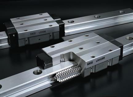
2 Advanced original design our-row Roller Type Linear Roller Way Compact block type LRXS is newly introduced. Dimensional interchangeable with a ball type 1 2


 LWTG (Ball type) Parallel arrangement of cylindrical rollers 0 0 000 000 000 0")
3 Linear Roller Way Super X is a linear motion rolling guide, featuring high reliability, high rigidity, high accuracy, and smooth motion. our rows of cylindrical rollers are incorporated in a highly rigid casing, and the cylindrical rollers in each row are arranged in parallel to each other in well-balanced form to take full advantage of the excellent characteristics of cylindrical rollers. Super high rigidity Rigidity of linear motion rolling guide has a large influence on the performance of machines or equipment in which they are assembled. Very high rigidity of Super X is achieved owing to the excellent elastic deformation characteristics of cylindrical rollers which give smaller elastic deformation under load as compared with steel balls, and, in addition, to a large number of cylindrical rollers incorporated in the slide unit. Deflection m 1 LRXG1 T3 preload LRXG2 T3 preload LRXG3 T3 preload LRXG T3 preload LRXG T3 preload LRXG8 T3 preload xcellent vibration characteristics As compared with ball types of the same size, Super X has higher rigidity and gives smaller deformation under repeated fluctuating load. The natural frequency is high, and the vibration damping time is short. Compliance -9 m / 8 2 X alf amplitude X. e -2.. f0.. t X : Initial amplitude f0 : atural frequency : Damping factor t t : Time Vibration damping curve LRXG (Roller type) LWTG (Ball type) Parallel arrangement of cylindrical rollers Downward load lastic deformation characteristic of Linear Roller Way Super X Time 0.03 s 0.0 Vibration damping curve under downward excitation (half amplitude) 0.0 Structure of the re-circulating part of cylindrical rollers arranged in four rows Super high load capacity Cylindrical rollers give a larger contact area compared to steel balls, so higher load capacity is attainable when cylindrical rollers are used. Incorporating a large number of cylindrical rollers, Super X has very high load ratings. xcellent load balance and moment load capacity Cylindrical rollers are arranged in a well-balanced form so that they can uniformly withstand loads in all directions. In addition, rows are arranged in such a way that the moment arm distance between the loading points is large under T0 moment. A high moment load capacity can be obtained Structure of Linear Roller Way Super X Grease nipple Casing Cylindrical roller Under seal Retaining plate nd plate nd seal U.S. PATT o.,800,0 o.,193,91 o.,0,22 o.,,188 o.,37, o.,22,33 o.,17,17 o.,97,7 o.,,288 Basic static load rating LRX (Roller type) LW... B (Ball type) Size Comparison of basic static load ratings Low noise and high running performance Smooth and quiet motion is achieved by adopting the optimum design based on the analysis of roller re-circulation behavior. urthermore, as the number of load carrying cylindrical rollers is large, the minute fluctuating deflection during travel can be minimized. When T0 moment is applied Accurate positioning with excellent friction characteristics A unique roller retaining method is adopted, in which the end faces of cylindrical rollers are guided accurately by the retaining plate, so skew of cylindrical rollers is prevented and smooth motion is achieved. As compared with the slide guides and ball type linear motion rolling guides, Super X has superior frictional characteristics and gives small frictional resistance even under preload. Good response to micro feed and high positioning accuracy can thus be achieved. 3
4 1 asy to use Matching needs by wide variations Line up with track rail widths from to 0. They can be applicable to various machines and devices of small machines to large machines. LRX LRX1 LRX LRX2 LRX LRX3 LRX LRX LRX LRX8 LRXG0 Downsizing Due to a great load capacity of the roller type compared with the ball type, Linear Roller Way Super X series enables downsizing of the linear motion rolling guide with its abundant variations. It also enables downsizing of the machines or devices. or example < Ball type > In case of LW... B C 0= 000 ine Types of Slide Units for Selection to meet Application eeds lange type LRX Block type LRXD Compact block LRXS Low profile design compact type is newly introduced. Keeping the same load capacity and downsizing the machine. Keeping the same size and obtaining larger load capacity. Short Smaller size, yet higher load capacity! C 0= Same size and much higher load capacity! C 0= Standard LRX Roller type LRX Roller type igh rigidity long igh tact Quick positioning can be achieved by high rigidity and excellent vibration characteristics of roller type even with a large inertia caused by the latest high tact positioning devices. Inertia =ma Small posture alternation in high acceleration and quick stop. Standardized Stainless Steel Series Linear Roller Way Super X includes stainless steel series in which stainless steel is used for steel component. Stainless series Linear Roller Way Super X are more resistant to corrosion than high carbon steel series, so these products are most suitable for applications where the use of oil or grease (including rust preventive oil) should be avoided or kept to minimum and for use in clean rooms.
5 2 asy to use User friendly 3 asy to use Abundant Special Specifications Dimensional interchangeable with a ball type Liner Roller Way Super X is dimensional interchangeable with a ball type. Replacing by a roller type is possible without a design modification of the machine. < Roller type > Liner Roller Way Super X < Ball type > Linear Way 19 special specifications are prepared for Linear Roller Way Super X. They can be specified by the supplemental codes in the identification number. So the right item can be specified easily according to the applications when the customer orders. < Identification number > LRXC 3 C1 R0 T2 P S1 / asy specify lange type LRX LW... B Butt-jointing track rails -A1 -A1 -A2 -A2 -B1 -B1 -B2 -B2 Supplemental code /A Rail cover plate Capillary plates Capillary plates Supplemental code /PS /Q Block type Compact block LRXD LWD... B Opposite reference surfaces arrangement Specified rail mounting hole positions With caps for rail mounting holes Changed pitch of slide unit middle mounting holes alf pitch of track rail mounting holes /D / / /G /P Butt-jointing interchangeable track rail (for interchangeable specification) With double end seals nd seals /T /V W LRXS LWS... B Inspection sheet / Mounting can be made from top or bottom! (lange type) Six oil supply holes provided as standard specification. With female threads for bellows (for single slide unit or track rail) emale threads for bellows /J Matched sets to be used as an assembled group /W lange type slide unit can be mounted from top or bottom. rom size 3 to 0 models, oil/grease can be supplied from six positions. As the lubricating position can be selected according to the specification of the machine or equipment, design flexisibility is enhanced. Black chrome surface treatment luorine black chrome surface treatment /L /L Set a Specified grease With scrapers (for assembled set) Set b /Y /Z Without track rail mounting bolts /M With scrapers (for assembled set) o end seal / Applicable size 3,,,, 8 and 0 models. If the other specifications are required, please consult. 7 8

6 asy to use Interchangeable Specification, Three eatures of Interchangeability The track rails and the slide units of interchangeable specification Linear Roller Way Super X can be handled separately and can be assembled to make a set as required. Interchangeability of incomparable high level has been achieved through rigorous dimensional control of the slide units and the track rails on the basis of the original advanced manufacturing technology. At a time like this! Want to improve the rigidity and life of the machine Want to improve the accuracy of the machine Want to replace slide units right away umber of slide units insufficient Want to replace track rails right away Length of track rails not long enough Want to stock spare slide units for emergency Interchangeable specification can be useful. Urgent design change can be made. igh-accuracy and preload can be selected freely. s and track rails can be handled separately and combined freely. s and track rails can be stocked individually requiring only small stock area. A new product selection system is offered, in which slide units and track rails can be selected separately, as and when required!! Interchangeable slide unit Interchangeable with high accuracy Interchangeable with preload Various types of slide units with different sectional shapes and lengths are prepared. All of these slide units can be freely mounted on the same track rail. It is also possible to combine a slide unit and a track rail of different materials, for example, a high carbon steel slide unit and a stainless steel track rail can be combined. In addition, butt-jointing interchangeable track rails (supplemental code /T) can be butt-jointed for use. Two accuracy classes, igh and Precision are prepared for the interchangeable specification products so that these products can be used for applications requiring high running accuracy. eight variation among multiple sets is also controlled at a high accuracy level, ensuring that these products can be used for parallel track rail arrangement. igh accuracy dimensional control owing to a simple structure has made it possible to realize the interchangeability among preloaded slide units. These products can be used for applications requiring one step higher rigidity. igh carbon steel track rail C s with the same preload symbol are interchangeable for achieving high rigidity. lange type Block type Compact block type Stainless steel track rail Butt-jointing interchangeable track rail A D B Deflection m 0 LRX T2 preload LRX T3 preload Short Standard igh rigidity long Load
7 Identification number The specification of Linear Roller Way Super X is indicated by the identification number, consisting of a model code, a size, a part code, a material symbol, a preload symbol, a classification symbol, an interchangeable code, and any supplemental codes. qseries lange type mounted from the upper/lower side LRX 1 Block type mounted from the upper side LRXD Compact block type mounted from the upper side LRXS or available models and sizes, see Table 1. or the model code of a single track rail of interchangeable specification, indicate LRX. ote 1 The size models can be mounted from the upper side only. or mounting from the lower side, LRX can be used. Interchangeable specification Assembled set on-interchangeable specification Assembled set qseries wlength of slide unit Model code LRX C 3 C1 T2 P S1 / Z LRX 3 R0 P S1 / LRX C 3 C1 R0 T2 P S1 / Z LRX C 3 C1 R0 T2 P / Z wlength of slide unit esize of rolling guide Short Standard igh rigidity long C o symbol G, 1,, 2,, 3,,,, 8, 0 Table 1 Models and sizes of Linear Roller Way Super X Material igh carbon steel made Stainless steel made Shape lange type Block type Compact block Block type ote 1 The interchangeable specification is not available. rumber of slide units Assembled set C C1 or available models and sizes, see Table 1. or available models and sizes, see Table 1. Size Model LRXC LRX 1 LRXG 1 1 LRXDC LRXD LRXDG LRXSC LRXS LRXSG LRXDCSL LRXD SL LRXDGSL or an assembled set, indicate the number of slide units assembled on one track rail. or a slide unit, only C1 can be indicated. esize of rolling guide Size tlength of track rail Assembled set R R Indicate the length of track rail in. or standard and maximum lengths, see Table 17 on page 27. rumber of slide units ymaterial igh carbon steel made o symbol Stainless steel made SL or available models and sizes, see Table 1. tlength of track rail Part code upreload amount Standard Light preload Medium preload eavy preload o symbol T1 T2 T3 Specify this item for an assembled set or a slide unit. ote that, for the slide unit of interchangeable specification, the preload amount that can be specified differs depending on the size. or details of preload amount, see Table 3 on page 13. ymaterial upreload amount Material symbol Preload symbol iaccuracy class igh Precision Super precision Ultra precision P SP UP The super precision classspand the ultra precision classupapply to the non-interchangeable specification products. In case of interchangeable specification products, assemble track rails and slide units of the same accuracy class. or details of accuracy, see Table 2 on page 13. iaccuracy class Classification symbol ointerchangeable code Select group S1 Select group S2 S1 S2 Specify this item for interchangeable specification products. Assemble track rails and slide units with the same interchangeable code. Performance and accuracy of S1 group and S2 group are the same. ointerchangeable!0special specification Interchangeable code Supplemental code!0special specification A, D,,, G, P,, J, L, L, M,, PS, Q, T, V, W, Y, Z or applicable special specifications, see Table on page kgf0.228lbs inch
8 Accuracy Preload Special Specifications Accuracy of Linear Roller Way Super X is shown in Table 2. Table 2 Accuracy C A D Classification Symbol Item Dim. tolerance Dim. tolerance Dim. variation of 2 Dim. variation of 2 Dim. variation of for multiple assembled sets 3 Parallelism in operation of C to A Parallelism in operation of D to B B igh Precision Super 1 precision Ultra 1 precision P SP UP See ig. 1. See ig ote 1 Applicable to the non-interchangeable specification products. 2 Variation between slide units mounted on the same track rail 3 Applicable to the interchangeable specification products. Parallelis 0 0 Length of track raill igh PrecisionP Super precisionsp Ultra precisionup ig. 1 Parallelism in operation unit The average amount of preload for Linear Roller Way Super X is shown in Table 3. or slide units of interchangeable specification, the type of preload that can be specified differs depending on the size. The applicable preload types for each size are shown in Table. When both rigidity and vibration characteristics are important, the standard preload amount is 1/2 of the applied load. Table 3 Preload amount Preload type Item Symbol Preload amount Standard o symbol 0 1 Light preload Medium preload eavy preload T1 0.02C0 T2 0.0C0 T3 0.08C0 ote 1 Zero or minimal amount of preload RemarkC0 means the basic static load rating. Table Preload type Preload type Standard o Light preload symbol T1 Interchangeable specification LRX LRX 1 LRX LRX 2 LRX LRX 3 LRX LRX LRX on-interchangeable specification Application Smooth and precise motion Minimum vibration Load is evenly balanced. Smooth and precise motion Medium vibration Medium overhung load Vibration and/or shocks Large overhung load eavy cutting Medium preload T2 eavy preload T3 RemarkThe above table shows representative model numbers but is applicable to all models of the same size. Linear Roller Way Super X of the special specifications shown in Table are available. When a special specification is required, add the applicable supplemental code to the end of the identification number. Table Special specifications Special specification Supplemental Interchangeable specification on-interchangeable code Assembled set specification Butt-jointing track rails A Opposite reference surfaces arrangement D Specified rail mounting hole positions Caps for rail mounting holes Changed pitch of slide unit middle mounting holes G alf pitch of track rail mounting holes P Inspection sheet emale threads for bellows J Black chrome surface treatment L 3 luorine black chrome surface treatment L 3 Without track rail mounting bolts M o end seal Rail cover plate for track rail PS 7 Capillary plates Q Butt-jointing interchangeable track rail T Double end seals V Matched sets to be used as an assembled group W 3 Specified grease Y Scrapers Z ote 1 Applicable to LRX, LRXG, LRX and LRXG. 2 ot applicable to size models. 3 ot applicable to size 8 models. ot applicable to size 0 models. Table.1 Combination of supplemental codes Interchangeable specification G P J L L M Q T V Y Z D G P J L L M Q T V Y Remark 1In the table, the mark indicates that this combination can be made. 2or combinations marked, consult for further information. When a combination of several special specifications is requiredsee Table.1 &.2, arrange their supplemental codes in alphabetical order. ot applicable to stainless steel series. ot applicable to size,, 8 and 0 models. 7 Applicable to size 3, and models. Table.2 Combination of supplemental codes on-interchangeable specification D G P J L L M PS Q V W Y Z A D G P J L L M PS Q V W Y RemarkIn the table, the mark indicates that this combination can be made. 13.2kgf0.228lbs inch 1
9 Butt-jointing track rails A -A1 -A1 -A2 -A2 With caps for rail mounting holes Cap Synthetic resin made With female threads for bellowsfor single slide unit or track rail J JR JL emale threads for bellows -B1 -B1 -B2 -B2 When the required length of non-interchangeable specification track rail exceeds the maximum length indicated in Table 1, two or more track rails can be used by butt-jointing them in the direction of linear motion. or the length and the number of butt-jointing track rails, consult for further information. Opposite reference surfaces arrangement Reference mounting surface of slide unit D Specially prepared caps for track rail mounting holes are appended. These caps cover the track rail mounting holes to improve the sealing performance in the linear motion direction. Aluminum caps are also available. Consult for further information. Changed pitch of slide unit middle mounting holes L 2 L 2 L G emale threads for mounting bellows are provided on the interchangeable slide unit or the interchangeable track rail. or details of related dimensions, see Table 9. qj emale threads are provided at both ends of the slide unit or the track rail. wjr emale threads are provided at the right end of the slide unit in sight of mark. ejl emale threads are provided at the left end of the slide unit in sight of mark. With female threads for bellowsfor assembled set J JJ JR JS JJS emale threads for bellows Reference mounting surface of track rail The reference mounting surface of track rail is made opposite to the standard side. The accuracy of dimension including parallelism in operation is the same as that of standard specification. Specified rail mounting hole positions The pitch length between the two middle mounting holes of slide unit is changed. or this dimension, see Table 7. alf pitch of track rail mounting holes P emale threads for bellows or an assembled set of interchangeable or noninterchangeable specification, female threads for mounting bellows are provided on the slide unit and the track rail. or details of related dimensions, see Table 9. qj emale threads are provided at both ends of the track rail, and at the slide unit ends which are the closest to the track rail ends.in case only one slide unit is assembled, female threads are provided at both ends. wjj emale threads are provided at both ends of the track rail, and at all ends of all slide units.applicable, when the number of slide units is two or more. In case only one slide unit is assembled, indicate /J. ejr emale threads are provided at both ends of the track rail. rjs emale threads are provided at the slide unit ends which are the closest to the track rail ends.in case only one slide unit is assembled, female threads are provided at both ends. tjjs emale threads are provided at all ends of all slide units. Applicable, when the number of slide units is two or more. In case only one slide unit is assembled, indicate /JS. mark The mounting hole positions of track rail can be specified by specifying dimension at the left end, which is the distance from the mounting hole nearest to the left end of the track rail to the left end face of the track rail in sight of mark on the slide unit. When ordering, add the dimensionin after /. Dimension can be specified in a limited range. Consult for further information. /2 /2 The pitch of the track rail mounting holes is changed to 1/2 of the dimension of standard type. mounting bolts are appended in the same number as that of mounting holes. Inspection sheet The inspection sheet recording dimensions and, dimensional variations of and, and parallelism in operation of the slide unit is attached for each set. Black chrome surface treatment LC LR LCR A black permeable chrome film is formed to improve corrosion resistance. The surface is then coated with acrylic resin. qlc Treatment is applied to the casing. wlr Treatment is applied to the track rail. elcr Treatment is applied to the casing and the track rail. luorine black chrome surface treatment LC LR LCR After forming a black permeable chrome film, the surface is coated with fluorine resin for further improvement in corrosion resistance. This treatment is also effective in preventing the adhesion of foreign substances on the surface. qlc Treatment is applied to the casing. wlr Treatment is applied to the track rail. elcr Treatment is applied to the casing and the track rail. 1.2kgf0.228lbs inch 1
10 Without track rail mounting bolts M Bolts for track rail mounting are not appended. Butt-jointing interchangeable track rail for interchangeable specification T Matched sets to be used as an assembled group W With scrapersfor assembled set Z ZZ Scraper o end seal nd pressure plate nd seals at both ends of slide unit are replaced by end pressure platesnot in contact with the track railto reduce frictional resistance. The under seals are not assembled. This specification is not effective for dust protection. Rail cover plate Rail cover plate Capillary plates PS Snap fastener Q Capillary plate The rail cover plate is delivered as assembled on the track rail. After mounting the track rail, the top surface of track rail is covered with a U-shaped thin stainless steel plate for further improvement in sealing performance. Standard end seals must be replaced with the special end seals. When mounting the cover plate, refer to the attached instruction manual for rail cover plate. The capillary plate is assembled inside the end seal of the slide unit. It is impregnated with lubricant so that relubrication interval can be made longer. or the total length of the slide unit with capillary plates, see Table 8. A special interchangeable track rail of which both ends are finished for butt-jointing is provided. Use the track rails having the same interchangeable code for butt-jointing. or the non-interchangeable specification, indicate butt-jointing track rail /A. With double end sealsfor single slide unit V VR VL Double end seals are provided on the interchangeable slide unit for more effective dust protection. or the total length of the side unit with double end seals, see Table 8. qv Double end seals are provided at both ends of the slide unit. wvr Double end seals are provided at the right end of the slide unit in sight of mark. evl Double end seals are provided at the left end of the slide unit in sight of mark. With double end sealsfor assembled set V nd seal VV Double end seals are provided on the slide unit of assembled set of interchangeable specification or noninterchangeable specification for more effective dust protection. or the total length of the slide unit with double end seals, see Table 8. qv Double end seals are provided at the slide unit ends which are the closest to the ends of the track rail.in case only one slide unit is assembled, double end seals are provided at both ends. wvv Double end seals are provided at all ends of all slide units.applicable, when the number of slide units is two or more. In case only one slide unit is assembled, indicate /V. Set Set or two or more sets of Linear Roller Way Super X used on the same plane, the dimensional variation of of Linear Roller Way Super X is kept within the specified range. The dimensional variation of dimension in matched sets is the same as that of a single set. When ordering, indicate the number of sets, which is always represented by the number of track rails, after /W. Specified grease YCG YBR YG The type of pre-packed grease in the slide unit can be changed by a supplemental code. qycg Low Dust Generation Grease for Clean nvironment CG2 is pre-packed. wybr MOLYCOT BR2 Plus GreaseDow Corningis prepacked. eyg o grease is pre-packed. With scrapers for single slide unit Z ZR ZL Metal scrapers are provided on the slide unit of interchangeable specification. The scrapernon-contact typeis used to effectively remove large particles of dust or foreign matter adhering to the track rail. or the total length of the slide unit with scrapers, see Table 8. qz Scrapers are provided at both ends of the slide unit. wzr A scraper is provided at the right end of the slide unit in sight of mark. ezl A scraper is provided at the left end of the slide unit in sight of mark. Metal scrapers are provided on the slide units of assembled set of interchangeable specification or noninterchangeable specification. The scrapernon-contact typeis used to effectively remove large particles of dust or foreign matter adhering to the track rail. or the total length of the slide unit with scrapers, see Table 8. qz Scrapers are provided at the slide unit ends which are the closest to the ends of the track rail.in case only one slide unit is assembled, scrapers are provided at both ends. wzz Scrapers are provided at all ends of all slide units. Applicable, when the number of slide units is two or more. In case only one slide unit is assembled, indicate /Z. Table 7 Pitch of slide unit middle mounting holes Supplemental code /G L2 L LRX 1LRXG 1 LRX LRXG 1 LRX 2LRXG 2 LRX LRXG LRX 3LRXG 3 LRX LRXG LRX LRXG LRX LRXG LRXG 0 L 2 L unit ote 1 Also applicable to LRX and LRXG. 17.2kgf0.228lbs inch 18
11 Table 8 with capillary platessupplemental code /Q, with double end sealssupplemental code /V, and with scraperssupplemental code /Z Table 9.1 emale threads for bellowssupplemental code /J Size, 1,, 2, Size3,,,, 8, 0 Size 1,, 2, / Q Capillary plate L L1 Capillary plate / Q Capillary plate L1 Capillary plate b1 b2 2M 1depth 3 b1 b2 2M 1depth 3 Grease nipple 1 A-M3 L1 a1 a1 / V nd seal L L1 nd seal / V nd seal L1 nd seal D B 2M 2depth a3 a D B 2M 2depth a3 a a / Z Scraper With capillary plates Q L L1 With double end seals 1 V Scraper With scrapers 1 Z L1 L L1 L L1 L / Z Scraper With capillary plates Q L1 With double end seals 1 V Scraper With scrapers 1 Z L1 L1 L1 LRXC LRXC LRX LRX LRXG LRXG LRXC LRXC LRX LRX LRXG LRXG LRXC LRXC LRX LRX LRXG LRXG LRXC LRXC LRX LRX LRXG LRXG LRXC LRX LRX LRXG LRXG LRXG ote 1 The values for a slide unit with double end seals or scrapers at both ends are shown. RemarkThe above table shows representative model numbers but is applicable to all models of the same size. unit LRXC 1 LRX 1 LRXG 1 LRXDC 1 LRXD 1 LRXDG 1 LRXSC 1 LRXS 1 LRXSG 1 LRXC 2 LRX 2 LRXG 2 LRXDC LRXD LRXDG LRXSC LRXS LRXSG LRXC 2 LRX 2 LRXG 2 LRXDC 2 LRXD 2 LRXDG 2 LRXSC 2 LRXS 2 LRXSG 2 LRXC LRX LRXG LRXDC LRXD LRXDG LRXSC LRXS LRXSG a1 b1 b2 M1depth L1 3 3 a3 a M2depth M3 M3 M3 M Unit ote 1 The specification and mounting position of grease nipple are different from those of the standard specification product. The grease nipple of the size models is A-M. or grease nipple specifications, see Table. 2 Also applicable to LRXC, LRX and LRXG. 3 The values for a slide unit with female threads for bellows at both ends are shown. Remarkor the size 1 and models of flange type and compact block type, the dimension a is higher than the dimension of the assembly. or details, consult for further information. M3 M8 M8 M8 19.2kgf0.228lbs inch
12 Load Rating and Life Table 9.2 emale threads for bellowssupplemental code /J Basic dynamic load rating C Size 3,,,, 8 a2 a1 b3 b b1 b2 M 1depth a a1 a2 b3 b1 b b2 M 1depth a L1 The basic dynamic load rating is defined as the constant load both in direction and magnitude under which a group of identical Linear Roller Ways Super X are individually operated and 90 of those in the group can travel 0 x 3 meters free from material damage due to rolling contact fatigue. The dynamic load ratings of Linear Roller Way Super X are designed for equal load capacity in downward, upward and lateral directions. Upward load Downward load D B 2M 2depth a3 D B 2M 2depth a3 a1 a2 b1 b2 b3 b M1depth L1 1 a3 a M2depth LRXC 3 LRX 3 1 LRXG 3 LRXDC M3 LRXD LRXDG 3 LRXC LRX LRXG LRXDC 0 7 M 8 LRXD LRXDG LRXC LRX LRXG LRXDC 0 88 M 8 LRXD LRXDG LRXC LRX LRXG LRXDC 7 8 M LRXD LRXDG LRX 8 LRXG M ote 1 The values for a slide unit with female threads for bellows at both ends are shown unit M 8 M M M M Basic static load rating C0 The basic static load rating is defined as the static load that gives a prescribed constant contact stress at the center of the contact area between the rolling element and raceway receiving the maximum load. It is the allowable limit load that permits normal rolling motion. Generally, the basic static load rating is used in combination with the static safety factor. The static load ratings of Linear Roller Way Super X are designed for equal load capacity in download, upward and lateral directions. Static moment rating T0TXTY The static moment rating is defined as the static moment load that gives a prescribed constant contact stress at the center of the contact area between the rolling element and raceway receiving the maximum load when a moment See ig. 3.is loaded. It is the allowable limit moment that permits normal rolling motion. Generally, the static moment rating is used in combination with the static safety factor. T0 TX ig. 2 Load direction TY Lateral load ig. 3 Static moment rating direction.2kgf0.228lbs inch 21 22
13 Lubrication and Dust Protection Grease ipple Precautions for Use Life The rating life of Linear Roller Way Super X is obtained from the following formula. C L0 3 1 P where, LRating life 3 m CBasic dynamic load rating PDynamic equivalent loador Applied load If the stroke length and the number or strokes per minute are known, the life in hours can be obtained from the following formula. L Lh 2 2Sn where, LhRating life in hoursh S Stroke length n1umber of strokes per minutecpm Static safety factor The static safety factor of Linear Roller Way Super X is given in the following formula. where, C0 fs P0 3 fs Static safety factor C0Basic static load rating P0Static equivalent loador Applied load Table Static safety factor Operating conditions fs A quality lithium-soap base grease containing extremepressure additivesalvaia P Grease 2SLLis pre-packed in Linear Roller Way Super X. owever, the quality of any grease will gradually deteriorate as operating time passes. Therefore, periodic re-lubrication is necessary. The re-lubrication interval varies depending on the operating conditions of the rolling guides. A six month interval is generally recoended and, if the machine operation consists of reciprocating motions with many cycles and long strokes, re-lubrication every three months is recoended. Re-lubrication is performed from a grease nipple provided at the slide unit. Re-lubrication interval can be extended by using the special specification Capillary Platesupplemental code /Q. Also, re-lubrication and other maintenance works can be reduced. Linear Roller Way Super X is dust-protected with special rubber seals. But, if large amounts of fine contaminants are present, or if large particles of foreign matter such as dust or chips may fall on the track rail, it is recoended to provide protective covers such as bellows or telescopic shields for the entire linear motion mechanism. Bellows to match the dimensions of Linear Roller Way Super X are optionally available. They are easy to mount and highly effective for dust protection. If required, consult. Grease nipples shown in Table are assembled to each slide unit of Linear Roller Way Super X. Table Grease nipple Type LRX AM3 LRX 1 AM LRX LRX 2 BM Grease nipple Shape and dimension Width across flats M3 Width across flats. M R3 2.1 R3 Approx Width across flats M unit.2. qmounting surface, reference mounting surface, and general mounting structure To mount Linear Roller Way Super X, correctly fit the reference mounting surfaces B and D of Linear Roller Way Super X to the reference mounting surfaces of the table and the bed, and then fix them tightly.see ig.. The reference mounting surfaces B and D and mounting surfaces A and C of Linear Roller Way Super X are accurately finished by grinding. Stable and high accuracy linear motion can be obtained by finishing the mating mounting surfaces of machines or equipment with high accuracy and correctly mounting the guide on these surfaces. The slide unit reference mounting surface is always the side surface opposite to the mark. The track rail reference mounting surface is identified by locating the mark on the top surface of the track rail. The track rail reference mounting surface is the side surface above the markin the direction of the arrow.see ig.. C D Operation with vibration and/or shocks igh operating performance ormal operation Load factor Due to vibration and/or shocks during machine operation, the actual load on each rolling guide becomes greater in many cases than the theoretically calculated load. The applied load is generally calculated by multiplying the theoretically calculated load by the load factor indicated in Table 11. Table 11 Load factor Operating conditions fw LRX LRX 3 LRX LRX LRX LRX 8 LRXG 0 BM quivalent to A-M Approx. 7. Width across flats8 M0.7 JIS AM JIS APT18 JIS APT A B ig. Reference mounting surfaces and general mounting structure Reference mounting surface D B Smooth operation free from vibration and/or shocks ormal operation RemarkThe above table shows representative model numbers but is applicable to all models of the same size. Operation with vibration and/or shocks 1.3 mark mark ig. Reference mounting surfaces 23.2kgf0.228lbs inch 2
14 Mounting wmounting of the slide unit xcept the size models, the slide unit is provided with one or two mounting thread holes in the middle of width See ig..so that an applied load can be received with good load balance. When designing machines or equipment, ensure that these middle mounting holes of the slide unit can be securely tightened to obtain maximum performance of the guide. It is recoended to secure the screwing depths shown in Table 13 for the slide units of compact block type. Middle mounting hole of the slide unit ig. Middle mounting hole of the slide unit Table 13 Screwing depth of slide unit mounting holes for compact block type LRXS 1 LRXS LRXS 2 LRXS Recoended minimum depth RemarkThe above table shows representative model numbers but is applicable to all models of the same size. ecorner radius and shoulder height of reference mounting surfaces It is recoended to make a relieved fillet at the corner of the mating reference mounting surfaces as shown in ig.7. owever, in some series, corner radius R shown in Table 1 can also be used. Table 1 shows recoended shoulder heights and corner radius of the mating reference mounting surfaces Table 1 Shoulder heights and corner radius of the mating reference mounting surfaces h1 R LRX LRX 1 LRX LRX 2 LRX LRX 3 LRX LRX LRX LRX 8 LRXG 0 R Shoulder height h2 R Shoulder height R Corner radius h1 h2 Rmax unit RemarkThe above table shows representative model numbers but is applicable to all models of the same size. rmultiple slide units mounted in close distance When using multiple slide units in close distance to each other, actual load may be greater than the calculated load depending on the accuracy of the mounting surfaces and the reference mounting surfaces of the machine. It is suggested in such cases to assume a greater load than the calculated load. qwhen mounting multiple sets at the same time In the case of interchangeable specification Linear Roller Way Super X, assemble a slide unit and a track rail with the same interchangeable code S1 or S2. In the case of non-interchangeable specification Linear Roller Way Super X, use an assembly of slide unit and track rail as delivered without changing the combination. Special specification products of matched sets supplemental code /W are delivered as a group in which dimensional variations are specially controlled. Mount them without mixing with the sets of another group. wassembling a slide unit and a track rail When assembling the slide unit on the track rail, correctly fit the grooves of the slide unit to the grooves of the track rail and move the slide unit gently in parallel direction. Rough handling will result in seal damage or dropping of cylindrical rollers. The interchangeable specification slide unit is provided with a duy rail. The size, 1,, 2 and models of non-interchangeable specification are appended with a duy rail. This duy rail should be used for assembly. eaccuracy of mating mounting surfaces A load greater than the calculated load may act on Linear Roller Way Super X, depending on the accuracy of mating mounting surfaces and assembling accuracy. This will eventually give an adverse effect on the service life of Linear Roller Way Super X. Therefore, the accuracy must be carefully examined. The accuracy of mating mounting surfaces for track rail and slide unit and the assembling accuracy must be determined considering the operating conditions, required running accuracy and rigidity, etc. Also, the mounting structure must be examined to ensure accuracy and performance for reliable use of a linear motion rolling guide. When multiple sets are mounted, the parallelism between the two mounting surfaces of machines must be prepared, in general, as shown in Table 1. Table 1 Parallelism between two mounting surfaces Accuracy class igh Precision P Super precision SP unitm Ultra precision UP ig. 8 Cleaning of mounting surfaces ttightening torque of mounting bolts The standard torque values for Linear Roller Way Super X mounting bolts are shown in Table 1. When machines or equipment are subjected to severe vibration, shock, large fluctuating load, or moment load, the bolts should be tightened with a torque 1.2 to 1. times higher than the standard torque values shown. When the mating member material is cast iron or aluminum, tightening torque should be lowered in accordance with the strength characteristics of the material. Table 1 Tightening torque of mounting bolts Bolt size M. M 0.7 M 0.8 M 1 M 81.2 M1. M1.7 M M Tightening torque -m Carbon steel bolt Stainless steel bolt Strength division.9 Property division A ig. 7 Relieved fillet at the corner of the mating reference mounting surfaces toperating temperature The maximum operating temperature is 1C and a continuous operation is possible at temperatures up to 0 C. When the temperature exceeds 0C, consult. or the with capillary plates supplemental code /Q of special specification, operate Linear Roller Way Super X below 80C. Parallelism rcleaning of mounting surfaces Before assembling Linear Roller Way Super X, remove burrs and blemishes from the reference mounting surfaces and mounting surfaces of the machine using an oil-stone, etc., and wipe off rust prevention oil and dirt with clean cloth. M2. M23 M RemarkTightening torque for slide unit center mounting holes on flange typelrxc, LRX, LRXGsize 1,, 2,, and 3, are, recoended to be tightened with a torque 70 to 80% values of table kgf0.228lbs inch 2
15 Track Rail Length Standard and maximum lengths of track rails of Linear Roller Way Super X are shown in Table 17. s in any length are also available. Simply indicate the necessary length of track rail in in the identification number. or non-interchangeable track rails longer than the maximum length shown in Table 17, butt-jointing track rails are available upon request. In this case, indicate /A in the identification number. dimensions at both ends are the same unless otherwise specified. To change these dimensions, specify the specified rail mounting hole positionssupplemental code / of special specification. Table 17.2 Standard and maximum lengths of stainless steel track rails number of mounting holes L Table 17.1 Standard and maximum lengths of high carbon steel track rails Item Standard length Standard length Ln Pitch of mounting holes Standard range of Maximum length 2 Item Ln Pitch of mounting holes Standard range of incl. 1 under Maximum length 2 incl. 1 under LRX number of mounting holes 0 1 L LRX 1 LRX LRX 2 LRX LRX LRX LRX LRX LRX 8 LRXG ote 1 ot applicable to the track rail with female threads for bellowssupplemental code /J 2 s with the maximum lengths shown in parentheses can also be manufactured. Consult for further information. 3 LRX8 track rail maximum length of half pitchsupplemental code/pis RemarkThe above table shows representative model numbers but is applicable to all high carbon steel track rails of the same size. Unit Item Standard length Ln Pitch of mounting holes Standard range of incl. 1 under Maximum length 2 LRX SL LRX 1SL LRX SL LRX 2SL LRX SL ote 1 ot applicable to the track rail with female threads for bellowssupplemental code /J 2 s with the maximum lengths shown in parentheses can also be manufactured. Consult for further information. RemarkThe above table shows representative model numbers but is applicable to all stainless steel track rails of the same size. Unit 27.2kgf0.228lbs inch 28
16 Linear Roller Way Super X lange type mounted from the upper/lower side LRXCLRXLRXG W d1 W2 3 W d1 W2 3 3M1 2M1LRXC d L L1 L L1 L2 M1 M1 LRX LRXG 1 1 h 2 2 LRXC LRX LRXG LRXC 1 LRX 1 LRXG 1 LRXC 1 LRX 1 LRXG 1 LRXC 2 LRX 2 LRXG 2 LRXC LRX LRXG Interchangeable W LRXC LRX LRXG MassRef. Slide unit kg Track rail kgm Dimensions of assembly W LRXC LRX LRXG Models mounted from the lower side only 1 ote 1 LRXC, LRX, and LRXG can be mounted from the upper side only. or mounting from the lower side, LRXC, LRX, and LRXG which have the same dimensions as those of the above models can be used. 2 lengths L are shown in Table The directions of basic dynamic load ratingc, basic static load ratingc0, and static moment ratingt0, TX, TYare shown in the sketches below. The upper values in the TX and TY columns apply to one slide unit, and the lower values apply to two slide units in close contact. Remark 1The mark indicates that interchangeable specification products are available. 2The appended track rail mounting bolts are hexagon socket head bolts of JIS B 117 or equivalent. 3or grease nipple specifications, see Table. A grease nipple mounting thread is provided on the left and right end plates respectively Dimensions of slide unit 1 W2 W L1 L2 L d1 M M 7 8. M M M 8 M C, C0 T0 TX TY d3 Dimensions of track rail W d3 d h Mounting bolt for track rail Bolt sizelength M3 M1 M M2 M828 LRXC LRXC xample of identification number of assembled set L 2 Basic dynamic load rating 3 C Basic static load rating 3 C Static moment rating m -m LRX C2 R80 T1 P S2 / Size of rolling guide Preload amount Model code umber of slide units Standardo symbol LRXC Two slide units Light preloadt1 LRX Medium preloadt2 LRXG Length of track rail80 eavy preloadt3 T0 -m Accuracy class igh PrecisionP Super precisionsp Ultra precisionup TX TY Interchangeable code Select group 1S1 Select group 2S2 LRXC LRX LRXG LRXC 1 LRX 1 LRXG 1 LRXC 1 LRX 1 LRXG 1 LRXC 2 LRX 2 LRXG 2 LRXC LRX LRXG Special specification Caps for rail mounting holes.2kgf0.228lbs inch
17 Linear Roller Way Super X lange type mounted from the upper/lower side LRXCLRXLRXG d1 W W2 L L1 L2 L2/2 L2/2 9M1 d L L1 3M1 L1 L2 M1 L 1 h 2 3 W LRXG 8, LRXG 0 d3 3 LRXC L 1 LRXC 3 LRX 3 LRXG 3 LRXC LRX LRXG LRXC LRX LRXG LRXC LRX LRXG LRX 8 LRXG 8 LRXG 0 Interchangeable MassRef. Slide unit kg Track rail kgm Dimensions of assembly ote 1 lengths L are shown in Table The directions of basic dynamic load ratingc, basic static load ratingc0, and static moment ratingt0, TX, TYare shown in the sketches below. The upper values in the TX and TY columns apply to one slide unit, and the lower values apply to two slide units in close contact. 3 The track rail longer and equalthan 00 of LRX8, LRXG8 and LRXG0 have few threaded holes for purpuse by specified hanging bolt. More details, consult. Remark 1The mark indicates that interchangeable specification products are available. 2The appended track rail mounting bolts are hexagon socket head bolts of JIS B 117 or equivalent. 3or grease nipple specifications, see Table. Three grease nipple mounting threads are provided on the left and right end plates respectively Dimensions of slide unit 1 W2 W L1 L2 L d1 M M M M1 M1 M M C, C0 T0 TX TY Dimensions of track rail W d3 d h Mounting bolt for track rail Bolt sizelength M M M M M M80 Basic dynamic load rating 2 xample of identification number of assembled set LRX C2 R00 T2 P S2 / Size of rolling guide Preload amount Model code umber of slide units Standardo symbol LRXC Two slide units Light preloadt1 LRX Medium preloadt2 LRXG Length of track rail00 eavy preloadt3 C Basic static load rating 2 C Accuracy class igh PrecisionP Super precisionsp Ultra precisionup Static moment rating 2 T0 -m TX -m TY -m Interchangeable code Select group 1S1 Select group 2S2 LRXC 3 LRX 3 LRXG 3 LRXC LRX LRXG LRXC LRX LRXG LRXC LRX LRXG LRX 8 LRXG 8 LRXG 0 Special specification Caps for rail mounting holes 31.2kgf0.228lbs inch 32
18 Linear Roller Way Super X Block type mounted from the upper side LRXDCLRXDLRXDG W W2 W W2 3M1depth 2M1depthLRXDC d L L1 L L1 L2 M1depth M1depth LRXD LRXDG 1 1 h 3 3 W LRXDC LRXD LRXDG W d3 LRXDC L 1 LRXDC LRXDC SL LRXD LRXD SL LRXDG LRXDG SL LRXDC 1 LRXDC 1SL LRXD 1 LRXD 1SL LRXDG 1 LRXDG 1SL LRXDC LRXDC SL LRXD LRXD SL LRXDG LRXDG SL LRXDC 2 LRXDC 2SL LRXD 2 LRXD 2SL LRXDG 2 LRXDG 2SL LRXDC LRXDC SL LRXD LRXD SL LRXDG LRXDG SL Interchangeable MassRef. Slide unit kg Track rail kgm Dimensions of assembly ote 1 lengths L are shown in Table The directions of basic dynamic load ratingc, basic static load ratingc0, and static moment ratingt0, TX, TYare shown in the sketches below. The upper values in the TX and TY columns apply to one slide unit, and the lower values apply to two slide units in close contact. Remark 1The mark indicates that interchangeable specification products are available. 2The appended track rail mounting bolts are hexagon socket head bolts of JIS B 117 or equivalent. or stainless steel series Linear Roller Way Super X, stainless steel bolts are appended. 3or grease nipple specifications, see Table. A grease nipple mounting thread is provided on the left and right end plates respectively Dimensions of slide unit 1 W2 W L1 L2 L M1depth C, C0 T0 TX TY M. M8 M8 M M W Dimensions of track rail M M M M M828 xample of identification number of assembled set LRXD C2 R80 SL T1 P S2 /.2kgf0.228lbs inch 33 3 Model code LRXDC LRXD LRXDG Size of rolling guide d3 d h umber of slide units Two slide units Mounting bolt for track rail Bolt sizelength Length of track rail80 Basic dynamic load rating 2 Material C igh carbon steel madeo symbol Stainless steel madesl Basic static load rating 2 C Preload amount Standardo symbol Light preloadt1 Medium preloadt2 eavy preloadt3 Static moment rating 2 T0 -m TX -m Accuracy class igh PrecisionP Super precisionsp Ultra precisionup TY -m Interchangeable code Select group 1S1 Select group 2S2 LRXDC LRXDC SL LRXD LRXD SL LRXDG LRXDG SL LRXDC 1 LRXDC 1SL LRXD 1 LRXD 1SL LRXDG 1 LRXDG 1SL LRXDC LRXDC SL LRXD LRXD SL LRXDG LRXDG SL LRXDC 2 LRXDC 2SL LRXD 2 LRXD 2SL LRXDG 2 LRXDG 2SL LRXDC LRXDC SL LRXD LRXD SL LRXDG LRXDG SL Special specification Caps for rail mounting holes
1N 0.102kgf lbs. 1mm inch
 1 2 3 10.102kgf0.228lbs. 10.03937inch 7 10.102kgf0.228lbs. 10.03937inch 8 9 10.102kgf0.228lbs. 10.03937inch 10 Identification number The specification of Linear Roller Way Super X is indicated by the identification
Linear Way F LWF Ⅱ 133 Ⅱ 134
 Linear Way F 33 34 Linear Way F umber and Specification xample of an identification The specification of series is indicated by the identification. Indicate the identification, consisting of a model, dimensions,
Linear Way F. Linear Way F series. Linear Way F LWFF LWFH. Interchangeable. Wide structure. Flange type and block type.
 ide Rail Type Linear ay Linear ay LHLLS U.S. PATTD Linear ay is a linear motion rolling guide, featuring a wide track rail along which a highly rigid slide unit performs endless linear motion. A large
C-Lube Linear Way MV
 -Lube Linear Way 49 50 -Lube Maintenance Free Series -Lube Linear Way Long term maintenance free compliant! The aquamarine end plate is the symbol of maintenance free. Designation of Identification Number
C-Lube Linear Way MUL Linear Way U MUL LWU
 C-Lube Linear Way Linear Way U 1 16 C-Lube Maintenance Free Series C-Lube Linear Way long term maintenance free supported! The aquamarine end plate is the symbol of maintenance free. Identification umber
C-Lube Linear Way MLV MLV
 -Lube Linear Way 9 0 -Lube Maintenance Free Series -Lube Linear Way Long term maintenance free compliant! The aquamarine end plate is the symbol of maintenance free. Identification Number and Specification
Crossed Roller Ways. Description of each series and Table of dimensions. Anti-Creep Cage Crossed Roller Way
 Crossed Roller Ways Description of each series and Table of dimensions Crossed Roller Way Page - to -7 Anti-Creep Cage Crossed Roller Way Page - to - Crossed Roller Way Unit Page - to - In the table of
C-Lube Linear Way MUL Linear Way U
 C-Lube Linear Way Linear Way U 133 134 Aquamarine endplate for identification of C-Lube Linear Way Identifi cation number and specifi cation The specification of C-Lube Linear Way is indicated by the identification
C-Lube Linear Way ML Linear Way L
 -Lube Linear ay Linear ay L 3 Aquamarine endplate for identification of -Lube Linear ay Identifi cation number and specifi cation The specifications of series and LLseries are indicated by the identification
SRG. Caged Roller LM Guide Ultra-high Rigidity Type Model SRG. Point of Selection. Point of Design. Options. Model No. Precautions on Use
 Caged Roller LM Guide Ultra-high Rigidity Type Model LM block LM rail End seal Endplate 45 45 Caged roller Roller 45 Cross section 45 * or the caged roller, see. Point of Selection A Point of Design Options
C-Lube Linear Way MH Linear Way H MH LWH
 -Lube Linear ay M Linear ay ML -Lube Maintenance ree Series -Lube Linear ay M M long term maintenance free supported! Te aquamarine end plate is te symbol of maintenance free. Identification umber and
SHS. Caged Ball LM Guide Global Standard Size Model SHS. Point of Selection. Point of Design. Options. Model No. Precautions on Use
 Caged Ball LM Guide Global Standard Size Model LM block LM rail Endplate End seal 45 Ball Ball cage Cross section 45 * For the Ball Cage, see. Point of Selection Point of Design Options Model No. Precautions
NSK Linear Guides. Roller Guide RA Series. Extended series
 NSK Linear Guides A roller guide series employing advanced analysis technology offers super-high load capacity and rigidity. The RA series includes a complete lineup to handle a wide range of applications.
NSR-TBC. LM Guide Self-aligning Type Model NSR-TBC. Point of Selection. Point of Design. Options. Model No. Precautions on Use
 LM Guide Self-aligning Type Model LM casing Spline nut End seal LM rail Grease nipple Side plate Clearance adjustment bolt 90 Side seal (Optional) Ball Retainer Cross section 30 Point of Selection A Point
C-Lube Linear Roller Way Super MX Linear Roller Way Super X
 -ube inear Roller ay uper inear Roller ay uper X 14 Aquamarine endplate for identification of -ube inear ay Identifi cation number and specifi cation Te specification of -ube inear Roller ay uper is identified
Ball Rail Systems RE / The Drive & Control Company
 Ball Rail Systems RE 82 202/2002-12 The Drive & Control Company Rexroth Linear Motion Technology Ball Rail Systems Roller Rail Systems Standard Ball Rail Systems Super Ball Rail Systems Ball Rail Systems
Linear Guideways HG Series
 18 G99TE1-67 Linear Guideways 2-1 - Heavy Load Ball Type Linear Guideway HG series linear guideways are designed with load capacity and rigidity higher than other similar products with circular-arc groove
SSR. Caged Ball LM Guide Radial Type Model SSR. Point of Selection. Point of Design. Options. Model No. Precautions on Use
 Caged Ball LM Guide Radial Type Model Endplate LM block End seal LM 90 30 Ball Ball cage Cross section * For the Ball Cage, see A. Point of Selection A Point of Design Options Precautions on Use Accessories
Ballscrews / Linear Guideway General Catalog
 Ballscrews / inear Guideway General Catalog inear Guideway 2 Introduction of ach Series 2. eavy oad Type, MSA Series A. Construction Upper Retainer Carriage nd Seal nd Cap Rail Grease Nipple Ball 45 ower
511E. LM Guide General Catalog
 General Catalog A Classification Table of the s Ball Guide Caged Ball Type Full-ball Type Standard Type Standard Type Model SHS Global Standard Size Model SSR Radial Model HSR 4-way Equal Load Model SR
SVR/SVS. Caged Ball LM Guide Ultra-heavy Load Type for Machine Tools Model SVR/SVS. Point of Selection. Point of Design. Options. Model No.
 Caged Ball Guide Ultra-heavy Load Type for Machine Tools Model Protector 90 rail Ball cage Radial type model SVR Cross section 40 50 Ball * For the Ball Cage, see A. 4-Way Type Model SVS Cross section
2-9 RG Series High Rigidity Roller Type Linear Guideway
 G99TE17-136 2-9 High Rigidity Roller Type Linear Guideway 2-9-1 Advantages and features The new RG series from Hiwin features a roller as the rolling element instead of steel balls. The roller series offers
Profi le rail guides LLR
 Profi le rail guides LLR Content The SKF brand now stands for more than ever before, and means more to you as a valued customer. While SKF maintains its leadership as the hallmark of quality bearings throughout
Caged Roller LM Guide
 Caged Roller LM Guide SRG/SRN Ultra-high Rigidity Long-term Maintenance-free Operation Smooth Motion Wide Array of Options For details, visit THK at www.thk.com Product information is updated regularly
HSR. LM Guide Global Standard Size Model HSR. Point of Selection. Point of Design. Options. Model No. Precautions on Use
 LM Guide Global Standard Size Model Retainer plate Endplate End seal Grease nipple Ball Retainer plate Inner seal (Optional) Side seal LM rail Cross section 45 45 Point of Selection A Point of Design Options
2-1 HG Series - Heavy Load Ball Type Linear Guideway
 2 G99TE15-114 Linear Guideways 2-1 - Heavy Load Ball Type Linear Guideway HG series linear guideways are designed with load capacity and rigidity higher than other similar products with circular-arc groove
LM Guide Radial Type Model SR
 LM Guide Radial Type Model Endplate LM block Grease nipple End seal LM rail 90 Ball Retainer plate Side seal (Optional) Cross section 30 Point of Selection A Point of Design Options Model No. Precautions
Miniature Ball Rail Systems
 R310EN 2210 (2004.06) The Drive & Control Company 2 Bosch Rexroth AG Linear Motion and Assembly Technologies Miniature-BRS R310EN 2210 (2004.06) Linear Motion Systems Ball Rail System Standard Ball Rail
Linear Guideways QH Series
 G99TE17-136 2-6 Quiet Linear Guideway, with SynchMotion TM Technology The development of HIWIN-QH linear guideway is based on a four-row circular-arc contact. The HIWIN-QH series linear guideway with SynchMotion
Linear Bushing General Catalog
 General Catalog A Technical Descriptions of the Products B Product Specifications (Separate) Features and Types... Features of the... Structure and features... Dedicated Shafts for Model LM... Standard
R310EN 2302 ( ) The Drive & Control Company
 The Drive & Control Company") R31EN 232 (26.4) The Drive & Control Company Bosch Rexroth AG Linear Motion and Assembly Technologies Ball Rail Systems Linear Bushings and Shafts Ball Screw Drives Linear Motion Systems Basic Mechanical
R31EN 232 (26.4) The Drive & Control Company Bosch Rexroth AG Linear Motion and Assembly Technologies Ball Rail Systems Linear Bushings and Shafts Ball Screw Drives Linear Motion Systems Basic Mechanical
Introduction of Each Series
 12 Introduction of Each Series 12.1 eavy Load Type, MSA Series A. Construction LINEAR GUIDEWAY Upper Retainer Carriage End Cap End Seal Grease Nipple Ball Lower Retainer Rail 45 eavy Load Type, MSA Series
The Block Structure. Linear block SBG, SBS, SPG and SPS types are available. All blocks are dimensionally interchangeable.
 Circular arc groove Two pint contact structure of circular arc groove. It keeps the function of self-aligning and smooth rolling performance. 45 angle of contact Four rows of circular arc groove contact
C-Lube Linear Roller Way Super MX Linear Roller Way Super X
 -Lube Linear Roller ay uper Linear Roller ay uper X 14 148 Aquamarine endplate for identification of -Lube Linear ay Identifi cation number and specifi cation Te specification of and series are identified
G10TE HG Linear Guideway
 G10TE01-0310 I HG Linear Guideway Preface... 1 1... 1 1-1... 1 1-2... 2 1-3... 3 1-3-1 1-3-2 1-4... 4 1-4-1 1-4-2 1-4-3 1-4-4 1-4-5 1-5... 6 1-5-1 1-5-2 1-5-3 1-5-4 1-6... 9 1-7... 9 1-7-1 1-7-2 1-8...
Cross Roller Guide/Ball Guide General Catalog
 General Catalog A Product Descriptions Features and Types... A7-2 Features of the.. A7-2 Structure and Features... A7-2 Types of the.. A7-3 Types and Features... A7-3 Point of Selection... A7-4 Rated Load
Roller Follower General Catalog
 General Catalog A Product Descriptions Features and Types... A20-2 Features of the... A20-2 Structure and Features... A20-2 Types of the... A20-3 Types and Features... A20-4 Point of Selection... A20-6
Linear Bushing. General Catalog A-523
 Linear Bushing General Catalog A Technical Descriptions of the Products B Product Specifications (Separate) Features and Types... Features of the Linear Bushing... Structure and features... Dedicated Shafts
RSR. LM Guide Miniature Types Model RSR. Point of Selection. Point of Design. Options. Model No. Precautions on Use
 LM Guide Miniature Types Model Endplate LM block End seal LM rail Ball Grease nipple Cross section Point of Selection A Point of Design Options Model No. Precautions on Use Accessories for Lubrication
HSR-M1. LM Guide High Temperature Type Model HSR-M1. Point of Selection. Point of Design. Options. Model No. Precautions on Use
 LM Guide High Temperature Type Model Endplate SUS304 End seal (High temperature rubber material) LM THK-EX50 Ball SUS440C Side seal (High temperature rubber material) LM rail THK-EX50 Cross section 45
...components in motion. Miniature Linear Guideways
 ...components in motion Miniature Linear Introduction Miniature linear guideway systems are widely used throughout industry for precise, compact applications. Precise and Stainless The gothic arch shape
A LH Series. LH Series A162. (2) Ball slide shape
 Ball slide shape") Series -5-1.3 Series (2) all slide sape all slide Model Sape/installation metod ig-load type ype Super-ig-load type 1 1 (1) eatures 1. ig self-aligning capability (rolling direction) Same as te D combination
Series -5-1.3 Series (2) all slide sape all slide Model Sape/installation metod ig-load type ype Super-ig-load type 1 1 (1) eatures 1. ig self-aligning capability (rolling direction) Same as te D combination
114 NOSE SEIKO CO.,LTD NOSE SEIKO CO.,LTD
 114 NOSE SEIKO CO.,LTD NOSE SEIKO CO.,LTD 115 and Part Code Applicable axis diameter Feature Part Code 5 ~ 3 General purpose cam follower with screwdriver groove on the stud head. Available with stainless
2. HG Series Linear Guideway Four-row Super Heavy Load
 16 2. HG Series Linear Guideway Four-row Super Heavy Load 2-1 Features of the HG Series Linear Guideway 2-2 Construction of HG Series Block Cap End cap End seal (Double seals and scraper) Rail Grease nipple
series Linear guideways CG-serie 3.3 CG series
 series CG-serie 3.3 CG series 3.3.1 Properties of the linear guideways, series CG The HIWIN linear guideways of the CG series with O-arrangement of the ball tracks guarantee high torque loading capacity,
Courtesy of CMA/Flodyne/Hydradyne Motion Control Hydraulic Pneumatic Electrical Mechanical (800)
") 01_1 Miniature st Headline_36 Ball Rail pt/14.4 Systems mm second line 2 Linear Motion and Assembly Technologies Miniature Ball Rail Systems Ball Rail Systems Roller Rail Systems Linear Bushings and Shafts
01_1 Miniature st Headline_36 Ball Rail pt/14.4 Systems mm second line 2 Linear Motion and Assembly Technologies Miniature Ball Rail Systems Ball Rail Systems Roller Rail Systems Linear Bushings and Shafts
LINEAR RAIL BALL CHAIN TYPE
 LINEAR RAIL BALL CAIN TYPE Svanemærket tryksag 54-73 INDEX Index Product overview... 4-5 Dimension table RC/ERC... 6-7 Dimension table RC... 8-9 Dimension table ARC... 0-3 Dimension table & Grease... 4
506E. LM Guide Actuator General Catalog
 LM Guide Actuator General Catalog A LM Guide Actuator General Catalog A Product Descriptions 506E Caged Ball LM Guide Actuator Model SKR.. A2-4 Structure and Features... A2-4 Caged Ball Technology... A2-6
SRW NEW. Wide Type Roller Guide with Caged Technology
 NEW Roller Wide Type Roller Guide with Caged Technology Ultra-High Rigidity, Heavy Load Low Friction Long Service Life, Long-Term Maintenance-Free Operation SRW This catalog uses recycled paper. CATALOG
12.3 Full Roller Type, MSR Series
 12.3 Full Roller Type, MSR Series A. Construction Carriage End Seal Grease Nipple End Cap Inner Seal Roller Bottom Seal 45 Rail 45 B. Characteristics The full roller type linear guideway, MSR series, equip
Runner block FNS R Flanged, normal, standard height
 38 Bosch Rexroth Corporation Roller Rail Systems R310A 30 (007.06) Standard Runner Blocks, Steel version Runner block FS R1851... 10 Flanged, normal, standard height Further runner block versions with
Inner block. Grease nipple. Fig.1 Structure of LM Guide Actuator Model KR
 LM Guide ctuator Model LM Guide + all Screw = Integral-structure ctuator Stopper Housing all screw Inner block Grease nipple Outer rail earing (supported side) Housing Stopper Double-row ball circuit earing
HSR(Ct Grade) Cost effective Type (Ct Grade) of LM Guide Debuts STOCK DISPONIBLE ENTREGA INMEDIATA
 Cost effective Type (Ct Grade) of LM Guide Debuts STOCK DISPONIBLE ENTREGA INMEDIATA") Cost effective Type (Ct Grade) of L Guide Debuts A cost effective series of the well-established model HSR has been newly added. Optimal for the general linear guide market such as for conveyance systems!
Cost effective Type (Ct Grade) of L Guide Debuts A cost effective series of the well-established model HSR has been newly added. Optimal for the general linear guide market such as for conveyance systems!
LM Guide HCR/HMG. R Guide / Straight-Curved Guide Achieving a Simplified Mechanism. For details, visit THK at CATALOG No.
 LM Guide HCR/HMG R Guide / Straight-Curved Guide Achieving a Simplified Mechanism For details, visit THK at www.thk.com Product information is updated regularly on the THK website., CATALOG No.306-8E HCR
Miniature LM Guide RSR and RSR-W
 iniature Guide RSR and RSR End plate block rail End seal Ball Greace nipple ig. 1 onstruction of odel RSRV onstruction and eatures Balls roll in two rows of precisionground raceways on an rail and an block.
Features of the LM Guide
 Features of the Functions Required for Linear Guide Surface Large permissible load Highly rigid in all directions High positioning repeatability Running accuracy can be obtained easily High accuracy can
Wide Caged-roller LM Guide
 NEW Wide Caged-roller LM Guide Optimal for large machines that require high rigidity and mounting accuracy Ultra-high rigidity, heavy load A wide, large roller guide model is added to the lineup CATALOG
SRS. Caged Ball LM Guide Miniature Type Model SRS. Point of Selection. Point of Design. Options. Model No. Precautions on Use
 Caged Ball M Guide Miniature Type Model M rail Endplate End seal M block Compact type Model -M Ball Side seal Ball cage Wide type Model -WM * or the ball cage, see A. Point of Selection A Point of Design
Linear Guideways MG Series
 52 2-3 - Miniature Linear Guideway 2-3-1 Features of MGN Series 1. Tiny and light weight, suitable for miniature equipment. 2. All materials in special grade of stainless steel for anti-corrosion size
The Classification Chart of PMI Linear Guideways
 1 The Characteristics of MI s The Classification Chart of MI s 2 (1) igh positioning accuracy, high repeatability The MI linear guideway is a design of rolling motion with a low friction coefficient, and
2-3 Miniature MGN/MGW Series Features of MGN Series
 54 G99TE08-0405 2-3 Miniature MGN/MGW Series 2-3-1 Features of MGN Series 2-3-2 Construction of MGN Series Cap Block End cap End seal Grease nipple Ball Bottom seal Retainer Rolling Circulation System:
LM Roller General Catalog
 General Catalog A Product Descriptions Features and Types... A10-2 Features of the... A10-2 Structure and Features... A10-2 Types of the... A10-4 Types and Features... A10-4 Point of Selection... A10-6
Ball. Ball cage. Fig.1 Structure of Caged Ball LM Guide Actuator Model SKR
 Caged all LM Guide Actuator Model Inner block all screw shaft Grease nipple Outer rail all cage all Structure and Features Fig.1 Structure of Caged all LM Guide Actuator Model Caged all LM Guide Actuator
LINEAR GUIDES with Ball Retainer
 LINEAR GUIDES with Ball Retainer LGSR, LGSR-S Series LGHR, LGHR-F Series Low noise operation without collision of balls Suitable for high precision since vibration is canceled Linear Guide
Guide units. For toolmaking, fixture manufacturing and machine engineering
 Guide units For toolmaking, fixture manufacturing and machine engineering Guide units in compliance with DIN, ISO and STEINEL standards or according to your specifications Guide pillars Guide and pillar
12.5 Ball Chain Type, SME Series
 12.5 Ball Chain Type, SME Series A. Construction Carriage End Cap End Seal Grease Nipple Inner Seal Ball Bottom Seal Ball Chain 45 Rail 45 B. Characteristics The ball chain type linear guideway, SME series,
TS / CT TS / CT Ⅱ 195 Ⅱ 196
 19 196 Precision Positioning Table Ball screw TS Slide table Ball screw Linear Points Crossed Roller Way 1 High precision and compact positioning table slide tables and beds. High precision and compact
R310EN 2211 ( ) The Drive & Control Company
 The Drive & Control Company") eline Ball Rail Systems R310EN 2211 (2006.04) The Drive & Control Company Bosch Rexroth AG Linear Motion and Assembly Technologies Ball Rail Systems Roller Rail Systems Linear Bushings and Shafts Ball
eline Ball Rail Systems R310EN 2211 (2006.04) The Drive & Control Company Bosch Rexroth AG Linear Motion and Assembly Technologies Ball Rail Systems Roller Rail Systems Linear Bushings and Shafts Ball
NSK Standard Ball Screws High Speed SS Series
 NSK Standard Ball Screws igh Speed SS Series NSK s high speed and low noise ball screws provide high-level performance for drive systems of industrial machines such as those used in manufacturing. standard
Precision Linear Pack
 Precision Linear Pack General Catalog A Technical Descriptions of the Products B Product Specifications (Separate) Features... Features of the Precision Linear Pack... Structure and features... Rated Load
A SH Series. SH Series. 2. Ball slide shape
 S Series -5-1.2 S Series 1. eatures (1) ower noise and gentler tone Incorporating a retaining piece and optimizing te circulation pat enables steel ball circulation stability and te prevention of ball
Features of the LM Guide
 Features of the Functions Required for Linear Guide Surface Large permissible load Highly rigid in all directions High positioning repeatability Running accuracy can be obtained easily High accuracy can
RSR-M1. LM Guide High Temperature Type Model RSR-M1. Point of Selection. Point of Design. Options. Model No. Precautions on Use
 LM Guide High Temperature Type Model Endplate SUS34 LM block THK EX5 End seal (High temperature rubber) LM rail THK EX5 Ball SUS44C Grease nipple SUS34 Point of Selection A Point of Design Options Model
F-1 SLIDE GUIDE STROKE BALL SPLINE ROTARY BALL SPLINE BALL SPLINE TOPBALL PRODUCTS SLIDE BUSH SLIDE UNIT SLIDE ROTARY BUSH STROKE BUSH SLIDE SHAFT
 SLIDE GUIDE BALL SPLIE ROTARY BALL SPLIE STROKE BALL SPLIE TOPBALL PRODUTS SLIDE BUSH SLIDE UIT SLIDE WAY/GOIO WAY MIIATURE SLIDE F- ATUATOR SLIDE SREW The B stroke bush is a linear and rotational motion
(1) High positioning accuracy, high repeatability. (2) Low frictional resistance, high precision maintained for long period
 High positioning accuracy, high repeatability. (2) Low frictional resistance, high precision maintained for long period") Linear Guideway 1 The Characteristics of PMI Linear Guideways (1) igh positioning accuracy, high repeatability The PMI linear guideway is a design of rolling motion with a low friction coeffcient, and
Linear Guideway 1 The Characteristics of PMI Linear Guideways (1) igh positioning accuracy, high repeatability The PMI linear guideway is a design of rolling motion with a low friction coeffcient, and
...components in motion. Easy Rail
 ...components in motion Easy Rail Easy Rail Introduction The Easy Rail family have a compact cross-section and low-friction movement. Robust and Long Service Life Easy Rail s range of cross-sectional rail
LINEAR MOTION SYSTEM COMPONENTS
 R RECISION NDUSTRIAL OMPONENTS R LINEAR MOTION SYSTEM COMPONENTS LINEAR MOTION SYSTEM COMPONENTS PIC Design has added a most comprehensive selection of precision components for linear motion applications.
Easy Slide Rails ov -easy_slide_divider - U pdated
 Easy Slide Rails ov-easy_slide_divider - Updated - 18-09-2017 163 Easy Slide Rails Easy Slide Rails Introduction The Easy Slide family of linear rails have a compact cross-section and low-friction movement.
Linear Guideway General Catalog
 General Catalog General Catalog Index TY AG Contents Technical roducts TY AG 1 2 3 4 5 6 7 8 6 7 1 11 11 11 12 12 13 14 15 18 19 1. The Characteristics of MI s 2. The Classifi cation Chart of MI s 3. The
Compact FA Series. NSK Standard Ball Screws
 NSK Standard Ball s ompact Series ompact-nut ball screws with increased speed and low noise for NSK standard. They accommodate a variety of uses, from use in semiconductor equipment to various transfer
Precision Modules PSK
 Precision Modules PSK The Drive & Control Company Rexroth Linear Motion Technology Ball Rail Systems Roller Rail Systems Standard Ball Rail Systems Super Ball Rail Systems Ball Rail Systems with Aluminum
Profile rail guides LLT
 Profile rail guides LLT Contents The SKF brand now stands for more than ever before, and means more to you as a valued customer. While SKF maintains its leadership as the hallmark of quality bearings throughout
Miniature Linear Guideway MSC Stainless Steel Series
 Supreme Performance of High Precision 1 Construction Carriage End Cap End Seal Rail Ball Retainer Bottom Seal 4 4 2 Characteristics MSC stainless steel series are applied two rows with Gothicarch groove
SNR/SNS. Advantages of Caged Ball Technology. Revised basic dynamic load ratings
 Advantages of aged Ball Technology High speed performance Low noise design, Long service life Long-term maintenance-free operation Reduction in rolling resistance variation SNR/SNS Revised basic dynamic
Guide plate. Fig. 1 Construction of Slide Pack Type FBW-RUU
 A Slide Pack Slide Pack Type FBW Japanese patent No. 1696446 Overseas patent resistered in the U.S. Mounting plate Ball Slide rail Seal Guide plate Stopper Fig. 1 Construction of Slide Pack Type FBW-RUU
12.4 Miniature Type, MSC MSD Stainless Steel Series
 12.4 Miniature Type, MSC MSD Stainless Steel Series A. Construction Carriage End Cap MSC Standard Type End Seal Rail MSD Wide Type Ball Retainer Bottom Seal 45 45 B. Characteristics MSC st ows with Gothic-arch
Instruction Manual for the LM Guide
 Instruction Manual for the LM Guide 1 Table of Contents 1.Introduction 1 2.Precautions on Using the LM Guide 2 1.Introduction Thank you for purchasing the THK products. This document will explain any precautions
Compact Modules. with ball screw drive and toothed belt drive R310EN 2602 ( ) The Drive & Control Company
 The Drive & Control Company") with ball screw drive and toothed belt drive R310EN 2602 (2007.02) The Drive & Control Company Bosch Rexroth AG Linear Motion and Assembly Technologies Ball Rail Systems Roller Rail Systems Linear Bushings
with ball screw drive and toothed belt drive R310EN 2602 (2007.02) The Drive & Control Company Bosch Rexroth AG Linear Motion and Assembly Technologies Ball Rail Systems Roller Rail Systems Linear Bushings
FUNCTION OF A BEARING
 Bearing FUNCTION OF A BEARING The main function of a rotating shaft is to transmit power from one end of the line to the other. It needs a good support to ensure stability and frictionless rotation. The
JPF, BTK-V, MTF, WHF, BLK/WTF, CNF
 Rolled Models JPF, BTK-V, MTF, WF, BLK/WTF, CNF and BNT Point of Selection Options Model No. Precautions on Use Accessories for Lubrication Mounting Procedure and Maintenance A A B Lead Angle Accuracy
The Characteristics of PMI Linear Guideways
 Linear Guideway 1 The Characteristics of PMI Linear Guideways (1) High positioning accuracy, high repeatability The PMI linear guideway is a design of rolling motion with a low friction coeffcient, and
LM Guide Actuator KR. For details, visit THK at CATALOG No E. Product information is updated regularly on the THK website.
 LM Guide Actuator KR For details, visit THK at www.thk.com Product information is updated regularly on the THK website. CATALOG No.209-10E Integrated LM Guide and all Screw High-rigidity / High-precision
Linear Guideway. Technical Information.
 Linear Guideway Technical Information www.hiwin.com.tw Linear Guideways Technical Information Index Preface...1 1. General Information...1 1-1 Advantages and features of Linear Guideway...1 1-2 The principles
SRG. CATALOG No.270-4E
 Roller SRG CATALOG No.27-4E LM Guide with Caged Roller TechnologySRG LM rail LM block End seal End plate Pipe Retaining plate Caged Roller Roller cage Roller Caged roller retaining plates 45 45 Enlarged
Contents. Page. 1. Product description. 2. The AXC line of linear axes. 3. AXLT line of linear tables. AXC and AXS product overview...
 SNR Industry Contents Page 3 1. Product description AXC and AXS product overview... 6-8 Dynamic load ratings of the linear motion systems... 9 Compact modules... 10-11 Linear tables... 12 Telescopic axes...
A LH Series. LH Series. 2. Ball slide shape
 Series -5-1.1 Series are also available in randam matcing. (Special ig-carbon steel products for 15 to 45) 2. all slide sape all slide Model Sape/installation metod ype (Upper row, Rating: ower row, all
Any reproduction, even partial, is allowed only by written permission by Rollco.
 LINEAR UNIT E-SMART Every care has been taken to ensure the accuracy of the information contained in this catalogue, but no liability can be accepted for any errors or omissions. We reserve the right to
Ball Screw Support Bearings
 Ball Screw Support Bearings. Ball Screw Support Bearings CONTENTS. Ball Screw Support Bearings q Angular contact thrust ball bearings A-BST series w Duplex angular contact ball bearings HT series e Needle
Track Rollers/ Cam Followers
 Track Rollers/ Cam Followers Page Nomenclature...................................... 460 Introduction....................................... 462 Identification....................................... 462
Precise Stable Durability High Rigidity. Meet the Multi-Demand of Accuracy and Efficiency
 Precise Stable Durability High Rigidity Meet the Multi-Demand of Accuracy and Efficiency Linear Guideway B1-1 The Characteristics of PMI Linear Guideways High positioning accuracy, high repeatability