Content. Planetary Features. Application. Prestigious Clients.
|
|
|
- Donna Stanley
- 5 years ago
- Views:
Transcription

1 PLANETAR ARY DRIVES 1
2 Power er Transmission People Planetary Features Coaxial Input and Output Input and Output Rotation in same direction Compact in Size Flange and Foot ounted Efficient Speed Reduction Torque ultiplication Reversible Drive igh Shock Load Capacity Suitable for Continous Cyclic Loads Installation in any Postion Application. obile Cranes and Overhead Cranes Derrick and Shipboard Cranes Dredging Equipments Road aking achinery aterial andling Equipments Goods and Personnel Elevaters Sugar Crystalizers and ill Drives Construction Equipments and Conveyors Prestigious Clients. Crompton Greaves. SAIL Steel Plants. umbolt Wedag. Kirloskar Group. L & T, umbai. aruti dyog. DGP Windsor. Thermax Ltd. Nestle India. TELCO Ltd. Byer India. ECIL Ltd. SPIC Ltd. TIL Ltd. Escorts Ltd. IPCL Ltd. Gujarath Apollo...and countless more....and countless more. Content Particulars 1. General Information Company Profile 2 Introduction 3 General Information 3 Operating Temperature 3 Working Principle 4 aterial Construction 4 odel Codification 5 2. Technical Information omentary Overloads 6 Shrink Discs 6 Installation 7 Lubrication 7 Storage 8 3. Selection Procedure Symbol sed 9 Service Factor 9 Torque Ratings 9 Thermal Power 9 Selection Examples 9 4. Load Rating Load Classification 15 Load Location Factor 16 Output Load Rating 17 Input Load Rating Technical Data otorised Selection Dimensional Details 53 Foot ollow Input 54 Foot Free Input 56 Flange ollow input 58 Flange Free Input 60 Bevel Foot 64 Bevel Flange 68 Agitator Drive 70 Large Planetary 72 Shrink Disc Details 74 Output Shaft - ale Spline 75 Output Shaft - Female Spline 75 Output Shaft - ollow Keyed 76 otor ounitng Details Planetary Applications Enquiry Data sheet 80 Page No. 2
3 Company Profile In a span of twenty-two years we have grown to be the leader in POWER TRANSISSION PRODCTS of various types in India. We have supplied more than 55,000 Gear Boxes of Cycloidal type and over 35,000 of Planetary type and also exported more than 5000 Gear Boxes in last six years. We also manufacture Torque Limiters, Shaft ounted Drives, Winches, Track Drives, Slew Drives, Pump Drives and Custom Built Drives to the specific requirement. Products are manufactured with strict adherence to highest quality standards, our product range guarantees precise and trouble free performance for years together. A true testimony to the top quality of our products has been their wide acceptance. Our manufacturing unit is situated at Satara, 250 Kms. southeast of umbai and is equipped with hi-tech, state-ofthe-art machines and qualified well-trained manpower. Design, Research and Development is our strength. Continuous research is on, to incorporate innovative design features, so as to offer a best possible solution to customer for its power transmission requirement. Our products are used successfully in a wide range of industries all over the India and exported to developed countries. The power transmission products are designed and manufactured with our own technology and practical experience of highly qualified technocrats. The high quality components manufactured with the help of sophisticated machinery are indispensable both for trouble free operation and splitting of power transmission through multiple meshing. The multiple meshing allows power transmission through several paths and ultimately compact design. Our design experiences combined with extensive computer facility enable us to offer optimum solutions to any required application in a short time. We received ISO-9001 quality certificate from DNV in April 2001 and maintained till date. Customer satisfaction is our motivation and strength. We export to: Canada Germany Italy France Norway iddle East England nited States Australia Newzeland Netherland Sweden 3

4 General Information Introduction Our manufacturing unit is situated at Satara, 250 Kms. south-east of umbai and is equipped with hitech, state-of-the-art machines and qualified, well trained manpower. We have our own foundry to supply special grade quality castings. Design, Research and Development is our strength. All the products are developed and manufactured with own technology. Continuous research is on, to incorporate innovative design features, so as to offer a best possible solution to customer s power transmission requirements. General Information Before a reducer can be selected for any application, the equivalent output torque or horse power must be computed by multiplying the actual or specified torque or horsepower by the service factor ( SF ) for the particular load classification for which the unit is to be used. It is necessary that the unit selected have a capacity equal to or in excess of the equivalent output torque in Nm or horsepower. Operating Temperature It is important that the maximum oil temperature should not exceed F (93 0 C). If a continuous ambient temperature of F (46 0 C) or higher exists. Please contact the factory. Thermal limitations may exist for some units with low ratios. eat exchangers are available for these applications that exceed the thermal capacity of reducers. For unusual application requirements such as those listed below, consult the factory for assistance. - Ambient temperature less than 15 0 F (-9 0 C) or more than 120 o F (50 o C). - Corrosive, chemical or explosive fumes. - Inclined or azimuth mounting or rotating body or sub merged requirements. - nusual atmosphere such as vacuum, high pressure, or high altitude. Reducer can be selected by service factor or load classification. Both service factors and load classification are a means of classifying different equipment and applications into a uniform guideline useful for reducer selection. Due to variations in application, service factors are used to adjust equipment ratings to accommodate differing load conditions. Applications involving unusual or severe load condition should be carefully reviewed before a service factor is applied. Care must be taken by the customer to isolate the reducer from unplanned transient load or vibrating conditions. 4
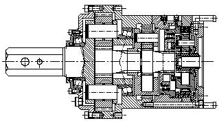
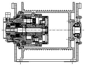
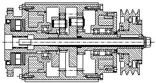
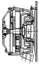
5 General Information Working Principle. The simple planetary comprises of sun gear, planet, planet carrier assembly and ring gear. Coaxial sun gear and planet carrier assembly which comprises of carrier and the planets rotating at constant centres along with the planet carrier. The input is from sun gear and the drive motion through the planet carrier via planets and ring gear is generally stationery. The rolling contact of the planets with the ring gear provides the appropriate reduction ratio. By varying the number of teeth of sun gear and planets it is possible to achieve various different ratios per stage. ulti-stage gear boxes are available by connecting the individual stages in sequence. n 2 n 1 aterial Construction Ring Gears Ring gears are manufactured from high alloy steel and heat treated to absorb impact loads and give desired wear life, the production process selected to avoid distortion of gear teeth due to heat treatment. Planets Planets are manufactured from high alloy steel and heat treated for case carburising or nitriding to achieve the optimum strength and wear resistance. Planet bores are ground and honed to achieve desired finish and tolerance. Gear Teethes are ground for model 4003 and above to reduce noise level. To increase load carrying capacity and uniform load distribution, planets are selected in sets. Sun Gear Sun Gears are manufactured from high alloy steel and heat treated for case carburising or nitriding to achieve the optimum strength and wear resistance. Sun gears are mounted on input shaft or carrier with the help of splines and in small models with keyways to achieve desired power transmission. Planet Carriers Planet carriers are manufactured from high alloy steel casting or forging or bars and machined with CNC machining center to achieve desired accuracy of planet pin holes runout and parallality. Output / Input Shafts Shafts are manufactured from high alloy steel and heat treated to achieve maximum strength to transmit power and absorb high impact load. The input motion from sun gear (1) is transmitted via planets and finally to coaxial planet carrier (5). Planets (2) simultaneously engages with sun gear (1) and the ring gear (3), The input rotation n 1 applied to the sun gear is reduced to the output rotation n 2. The ring gear (3) fixed to the frame functions as the reacting gear component. Input and output rotates in the same direction. The power is transmitted simultaniously through multiple planets and hence high power transmission is possible in small size and will result in less weight. Casing / ousing Casing Foot or Flange type are designed to absorb vibration and support reaction loads. These are manufactured from graded cast iron or cast steel according to power transmission and designed to optimum weight to power ratio. Broughtout parts All standard parts such as bearings, seals, hardware are procured directly from reputed manufacturers for genuineness and cost effectiveness. The Product is designed with the help of computers for the optimum power to weight ratio. All components are designed in keeping stringent requirements. 5
6 odel Identification 1. ounting - - orizontal. V - Vertical shaft down. W - Vertical shaft upward. 2. Input - F - Free J - ollow - Geared otor 3. ounting ethod - - Foot F - Flange A - Agitator 4. odel No. - x x x x - Standard Number B - With Bevel Input W - With Worm Input - With elical Input 5. Stages Single 2 - Double 3 - Triple 4 - Four 6. Reduction Ratio x x x x 7. Special - X - Indicates model to which specialized or modified specifications are adopted. Example 1 Example - 2 Example orizontal V - Vertical down W - Vertical up F - Input free J - Input hollow F - Input free - Foot mounting A - Agitator mounting F - Flange mounting Standard model Agitator model 4009B - Right Angle (Bevel) 2 - Double stage 3 - Triple stage. 2 - Double stage :1 - Reduction ratio :1 - Reduction ratio 43.47:1 - Reduction ratio F V J A W F F 4009 B
7 Technical Information omentary Overloads The maximum momentary or starting load applied to a reducer must not exceed 200% of rated load (100% overload). Rated load is defined as the reducer rating at a service factor of 1.0. Applications with high torque and for intermittent operations refer to the factory. Also applications where extreme repetative shock occurs or when high-energy loads are required to be absorbed, require special considerations and should be refered to the factory. Brake Loads When drives are equipped with brakes on the input, and the torque rating of the brake exceeds the rating of the motors, the rating of the brake dictates the selection of the reducer. Thermal Capacity It is the maximum orse Power, that can be transmitted without over heating at maximum oil temprature of 90 0 C when reducer is operated continously under standard oil bath lubrication. eat exchangers can be provided for those applications that are thermally limited. For the specific requirements contact factory. Lubrication Planetary Drives are shipped without oil and must be filled to the specified oil level before start-up. Lubrication and oil capacities are listed in the instruction and maintenance anual. ulti-speed Selections Reducers those will be operated at a variety of input speeds must be selected for the speed that yields the highest output torque requirement Gear Ratios The gear ratios are designed to avoid hunting and hence ratios are not whole numbers, any possible ratio can be manufactured specially according to requirement. Service Life The load ratings in the data sheets are based on number of output load cycles at a service factor of 1. The required service life must be specified when ordering, to select the speed reducer unit correctly, with a suitable service factor. Shrink Disc Assembly The shrink discs are supplied ready for mounting and well lubricated. owever, before re-assembly the shrink discs should be lubricated again. This also applies to the tapered ring surface as well as to the screw threads. For this purpose, a moly sulphide containing grease such as olykote BR 2 - should be used. When reassembling, it is important that all screws are within the sealing ring. Damaged sealing rings must be replaced. When putting the shrink discs on to the hub to be braced, the seat for the shrink discs on the hub must also be lubricated to avoid any possibility of corrosion. Contact surface of the shrink disc hub bore and the shaft must be free from grease. the safety of the torque transmission depends upon it to a great extent. nder no circumstances screws should not be tightened if the shrink disc is not mounted; otherwise, the inner ring will be deformed permanently. The same permanent deformation happens to the hub if not mounted on the shaft. Before putting the shrink disc on to the hub, both discs should be drawn against each other by tightening lightly and carefully by means of a small wrench so that the inner ring can just be turned. ake sure that the faces of both discs are absolutely parallel by checking at various diameters of both disks. The complete shrink disc set is then pushed on the hub. Then all screws be tightened carefully and evenly only so far that the shrink disc set cannot be turned on the hub by hand, even when using possible force. The screws must be tightened evenly and gradually, using a wrench of adequate size, always make sure that the two discs remains parallel. Shrink Disc Dismantling Exactly in the same way as in bracing, the screws will be loosened evenly and gradually to avoid tilting of the discs. The steep taper angle of the discs has been chosen to absolutely secure the opening of the shrink disc. Thereby the hub widens again and can easily be pulled off from the shaft, incase if the shaft is not free mounted shaft should be locked and input shaft to be rotated to seperate out output shaft of gearbox and mounted shaft.whilst the shrink disc remains on the hub. Attention Do not remove screws completely as long as the two outer rings are not free from their tapered seats. Remove any corrosion on the shaft in front of the hub. Before any new bracing, the shrink disc set should be lubricated again, the sealing ring should be renewed. Check easy fitting of the screw. 7
8 Installation All Speed Reducers should be mounted on vibration-free, solid, level foundation. The normal method of mounting is orizontal. When mounting the gear units, check that the breather, oil level and drain plugs are in the correct position. These will vary according to the mounting position. Foundation When mounting on structural steel, use of a rigid base plate is strongly recommended. The base plate should be designed to minimize bending and twisting. The base plate must be flat to prevent distortion of the unit. The base plate should extend the entire length of the unit. Clamp the unit securely to the structural steel support. When mounting on concrete base grout structural steel mounting pads into the mounting base, the reducer is then installed and shimmed off the structural pads, if shims are used to level or align the unit, they should be distributed evenly under all mounting pads to equalize the support load. se a feeler gauge to determine thickness of required shims. All pads must be squarely supported to prevent the distortion of the housing when the unit is bolted down. In case of installation with shocks, long duration over loads or frequent stopping, it is necessary to install motor protections, such as hydraulic coupling clutches. Alignment Align reducer with driven equipment by placing broad flat shims under all mounting pads of the reducer. Start at the low speed end and level across the length and width of the reducer. Check with feeler gauge to make certain that all pads are supported to prevent distortion of housing when reducer is bolted down. After reducer is aligned with driven equipment and bolted down, align prime mover to the reducer input shaft. The reliability and long life of the reducer requires careful installation of accessories and accurate alignment of the connecting shafts. After first week check alignment of the total system and realign if necessary. Also tighten the bolts and plugs as required. Remember to remove the load from the system before attempting to service the reducer. This action reduces the possibility of unexpected motion in the system. Check coupling for alignment to make sure that setting or vibration has not caused excessive misalignment. Load Connections ount sprocket, pulley and sheave as close as possible to the gear case in order to reduce the cantilever effect of overhang loads on the shaft bearings. Adjust belts or chains to manufacturer specification to prevent over tightening. Lubrication Determine minimum and maximum ambient temperatures the unit is to operate in. From the Ambient Temperature Table below, determine the proper AGA or ISO grade lubricant for those temperature conditions and select appropriate oil. se only SAE recommended grade as gear lubricants. Automotive oils are not recommended. All reducer are splash lubricated by gear rotation with even distribution to all gear meshes and bearings. Ambient Viscosity AGA ISO Temp. Grade Grade Grade -10 C to 15 C (15 F to 60 F) 10 C to 50 C (50 F to 125 F) If the speed reducer operates under extreme conditions or exposed to large temperature fluctuations, the use of synthetic oil is recommended. Note: The synthetic lubrication should conform to the requirements of ANSI/AGA 9005-D94. If the speed reducer operates in an environment where the temperature fluctuations are predictable, choose an oil viscosity that is recommended for the given temperature (i.e. for cold weather operation, use an oil that will circulate freely at all times.) The pour point of the oil should be 9 F (-5 C) or less than the minimum external temperature during reducer operation. During hot weather use higher viscosity oil that will not thin out and lose its lubricating qualities. Special measure should be taken to protect drives operating in direct sunlight at ambient temperature over 100 F(38 0 C).This protection can consist of a canopy/cover over the drive or reflective paint on the drive. If neither is possible, a heat exchanger nor other cooling device may be required to prevent the reducer sump temperature from exceeding the allowable maximum oil temperature of 90 C or 80 C. Cyclo Planetary Speed Reducers can be operated within oil temperatures from 20 C to 80 C. 8
9 Technical Information Lubrication Change Oil change must be carried out initially after first 100/200 hours of operation, and subsequently after every 2500 hours or at least every 12 months of operation. If operating under abnormal conditions such as high temperature sever duty, moisture or particle contamination, oil may need to be changed more frequently. Do not mix the oil of different types even of the same make. Never mix mineral and synthetic oils. Note : Oil samples should be taken from the oil level hole, not the drain hole. Storage Preparation for Storage. parts with rust preventive oil that is soluble in lubricating oil. Seal the reducer completely, and replace the vent plug with a solid pipe plug to keep rust inhibiting atmosphere inside. Periodically inspect stored or inactive reducers and add rust inhibitor every six months or more often if necessary. Dry indoor storage it is recommended to rotate shafts every three months to prevent bearings from becoming lacquered. Preparation for Start-p Fill reducer up to a proper oil level with the recommended lubricant. Remember reducers are supplied from the factory without oil. Rotate the shaft until the bearings move freely. Now the unit is ready to start-up. If reducer is to be stored or is likely to inactive after installation, drain oil from housing and spray all internal Table 1 Power Source Duration of working in ours per day Load Classification niformshock oderate shock eavy shock Electric motor, steam turbine nder or hydraulic motor 3 to Over ulti-cylinder internal nder combustion engine 3 to Over Single cylinder internal nder combustion engine 3 to Over
10 Technical Information Symbols used f s n 1 n 2 η t con t peak t eq h i Pt P Lf PD Fc To Teq P Kf n 1max = Service factor = Input speed (rpm) = Output speed (rpm) = Gearbox efficiency = Continuous Torque (Nm) = Peak Torque (Nm) = Equivalent Torque when gearbox is subjected to varying loads (Nm) = Number of working hours = Actual Reduction ratio = Thermal power of gearbox (kw) = orsepower = Load location factor = Pitch Diameter (mm) = Load connection factor = Required output Torque (Nm) = Equivalent Torque (Nm) = Required echanical Rating (kw) = Load correction factor on shaft = aximum Input speed (rpm) Service Factor (f s ) This is the factor depending on the application type table..2. It takes into consideration load variation, which the gearbox may undergo for the specific type of duty. It also takes into consideration the selected type of drive unit e.g. electric, hydraulic motor and so on and to be selected from table 1. Speed Input Speed (n 1 ) It represents the actual input speed of the gearbox. Output Speed (n 2 ) It represents the actual out speed of the gearbox. aximum input Speed (n 1max ) It represents the maximum input speed of the gearbox for the continuous operation that the gearbox can run for the specified life index. Reduction Ratio (i) It is the ratio of Actual input speed to actual output speed i = n1/n2 Torque Ratings Continuous Torque (t con ) This is the transmittable torque of the gearbox with continuous operation, that garantees a duration of h hours with a gearbox output rotation velocity of n2 RP. It is expressed as a function of the product n2 x h Peak Torque (t peak ) This is the maximum torque that the gearbox can transmit for short periods of time. Equivalent Torque (t eq ) It represents the value of the constant torque, which determines the same duration in hours of the torque induced by the work cycle. If T21 T2n are the torque transmitted by the gearbox at the output velocity n21. n2n for the time duration in hours of hi...hn, the equivalent torque is : teq = [ ( ( (n 21 * h 1 )/(n 2 *h) )* T ) + + ( ( (n 2n * hn)/(n 2 *h) )* T 2b 6.61 )] 1/6.61 Where, n2*h = (n 21 * h 1 ) + (n 22 * h 2 )+..+ (n 2n * h n ) Lifetime (n2 x h) It is the product of output speed and the duration in hours. It represents a number proportional to the stress applied to the element, which limits the life of the gearbox. To correlate the speed and the duration, the torque is expressed as a function of the product n2 x h. With the speed n2 and the torque tcon required the duration in hours can be calculated, or alternatively, if the speed and the duration in hours required are known then the tcon that the gearbox can transmit can be calculated. Example : Expected Life in hours = Output speed of the gearbox = 20 rpm 25000[h] * 20[n2] = [n2 x h] Thermal Power (Pt) aximum mechanical power transmitted by the gearbox while operating continuously, with splash lubrication, without exceeding the thermal limit of gear box (50 C above the ambient temperature). Greater powers can be transmitted by using an appropriate cooling system. The value refers to a continuous operation with input speed of 1440 rpm at ambient temperature 30 C. 10
11 Selection Procedure Information required for selection of the reduction unit : - The specific application - Working life in hours - Input speed - Input orsepower - Desired output speed - Over hung load etc. Selection of reducer is based solely on the required output torque capacity of the application at specified life duration. The Service factor method is used to apply specific industry application standards based on the hours per day of operation. These application standards are given in table-2 and have been developed based on practical application experience. Determine service factor (f s ) Selection of the Service factor is done as follows : - Depending upon driven machine or application decide the load classification (i.e. niform/oderate/eavy shock) from table 2. - Decide the prime mover and number of working hours per day By knowing above factors we can select service factor from table 1 Calculate the desired reducer ratio Reducer ratio = Input speed (RP)/Output speed (RP) Select Reduction ratio, that is closest to the desired ratio calculated as above. Calculate the equivalent output torque. When output torque is known (To) Equivalent Output torque (T eq ) = Output Torque(T o ) x service factor(f s ) When input motor horse power is known Output torque (Nm) = ( x P x fs x Eff ) Output speed Where : P = Input Power in horsepower fs = Service Factor from above Eff. = Drive Efficiency ( single = 96%, double = 92%, triple = 87%, four = 84%) Decide the life index (n2 x h) of the gearbox Life index (n2 x h) = output speed x life required in hours Example Output speed (n2) = 50 rpm Life required (h) = hours Life index (n2 x h) = 50 x = Select Reducer Locate the reduction ratio determined as above. Locate the smallest model, that offers the output torque (N-m.) rating that is equal to or greater than the equivalent output torque determined as above for the required reduction ratio and for required life index (n2 x h). i. e. Teq must be less than or equal to t con of the gearbox also peak torque requirement of the application must be less than the t peak of the gearbox Check thermal capacity (Pt) The motor horsepower capacity must be compared to the thermal capacity of the reducer and select the rating, which corresponds to the reducer model. If the motor horsepower is less than or equal to the rating, your application will not be thermally limited with respect to horsepower. If your motor horsepower exceeds this rating, contact the factory to review the possibility of increasing the thermal capacity by use of a heat exchanger. Thermal ratings can be ignored if continuous running time does not exceed idle time on a per hour basis. Check over hung load When over hung load exists on either input or output shafts, check that the overhung load exerted on input and output shaft are lower than or equal to values indicated in the chart for selected reducer model. In case they are greater than indicated value, change gearbox output version, gearbox size or system bearing arrangement. For correct modification according to your requirement contact factory. For each gearbox the radial loads for duration (n1 x h)= for input shaft and(n2 x h) = for the output shaft are shown in the diagram. For different durations applicable radial loads can be obtained by multiplying the values in the diagram by the correction factor K f 11
12 Selection Procedure Axial loads are given for various models along with maximum radial loads. ence these values must be checked against the axial loads. Check the breaking torque When drives are equipped with brakes on the input and the torque rating of the brake exceeds the rating of the motors, the rating of the brake dictates the selection of the reducer Calculations of the overhung load The centerline of the overhung load should be as close as possible to the seal cage to minimize bearing load and improve bearing life. The formula for determining overhung load in N. is as follows: Overhung load (N) = ( x P x Fc) / ( PD x RP (output) ) Seal Fr 1. Increase the pitch diameter of gear, Pulley or sprocket. 2. Locate the sprocket or belt closer to the Seal cage. 3. Go to the next larger reducer series. Check dimensions Dimensions drawings for reducers are given in the catalogue for free input and hollow input with foot and flange mounting. For your specific requirement contact the factory. Ordering reducers Specify the model, Reduction ratio, ounting, Input type and Specific requirements if any. Selection Examples When Output torque is known : A heavy-duty bucket elevator is operating at 24 hrs/day. The elevator requires a reducer with a 120 rpm output speed (1440 rpm input speed) and 2740 Nm. output torque. Overhung and thrust loads are bit a factor. Reducer will be driven with a 60-hp electric motor. Life index required (n2 x h) = Select service factor. Where: P PD RP Fc : orsepower without service factor. : Pitch Diameter in mm : Shaft revolutions per minute. : Load connection factor Load connection factor selection table Load connection factor (Fc) Sprocket or Timing Belt * 1 achined Pinion or Gear * 1.25 V-Belt 1.5 Flat belt 2.5 * Refer all multiple chain sprocket and pinion mounted If the actual overhung load exceeds the specified capacity, the following may assist to reduce the overhung load on the shaft bearings. The service factor for a heavy duty bucket elevator 24 hrs/day operation is 1.5. Calculate Required Reduction Ratio. Ratio = 1440 rpm /120rpm = 12. Select closest Reduction ratio i.e Output Speed = 1440/12.11 Calculate equivalent output torque = rpm. Since output torque is known : Teq = 2740 Nm. X 1.5 (SF) = 4110 Nm. Select Reducer. Reducer selection for Nominal ratio The smallest series listed for the design output torque as calculated as above is model having rating of 5821 Nm. For the life index (n2 x h)
13 Selection Procedure Check Thermal Capacity. Thermal capacity of odel , ratio is maximum 20 hp without any cooling arrangement and it can be increased up to 75 hp with cooling arrangement. Thus the application for 60 P requires cooling arrangement. Check for Overhung and Thrust Loads. Overhung and thrust loads are not a factor in this example. Check Dimensions. Dimensions for the model Order Planetary Gear Reducer. odel Name Nominal Ratio Output torque rating Nm. Input motor horsepower - 10 hp. Service Factor Input Speed rpm. Desired Accessories - with heat exchanger. When otor orsepower is known Example : 10 hp 1400-rpm electric motor is used to drive a heavyduty horizontal apron conveyor working 24 hrs/day. The conveyor requires a reducer output speed of 50 rpm. A roller chain drive having a 240 B 25 tooth roller chain sprocket having 600 mm Pitch Diameter which is mounted at the shaft center. The chain pull is acting at 76mm from the seal cage. Ambient temperature is 26 o C. Life index required (n2 x h) = Select service factor. The service factor for an apron conveyor. 24-hrs / day operation is 1.5. Calculate Actual reduction ratio. Reduction Ratio = 1440 /50 = 28.5 Select closest Reduction ratio Which is 27.5 Output Speed = 1440/27.5 = rpm. Calculate equivalent output torque. Equivalent output torque (Teq) = ( x10 hpx1.5sfx0.92)/52.36 rpm = Nm Select reducer Reduction ratio is The smallest series listed for the Output torque calculated as above model is a having rating of 2528 Nm. For life index (n2 x h) Check Thermal Capacity Compare the motor horsepower to the thermal ratings of the selected reducers. Since the motor horsepower is less than the thermal rating, the reducer s thermal capacity exceeds the motor capacity. Overhung and Thrust Loads. The overhung load exists on the output shaft. The input shaft is direct connected and does not encounter overhung load. Overhung load = x10hpx1.0/( 600 mmx52.36) = 4535 N Now from graph we find that for model overhung load for the life index (n2xh) and overhung load distance from seal cage 76 mm is equal to 8800 N.Now overhung load for the life index (n2 x h) = will be Overhung load = overhung load from graph * Kf From table Kf factor for life index equal to ence, Overhung load = 8800 * = 5146 (N) Thus the rated overhung load capacity is greater than the actual value, so the selection is approved. This application does not encounter thrust load. Check Dimensions. Order Planetary Gear Reducer. odel Name Nominal Ratio Output torque rating Nm. Input motor horsepower - 10 hp. Service Factor Input Speed rpm. Desired Accessories - none. 13
14 Selection Procedure Customer to fit the motor Electric motor 1 Determine the required torque at the output of gearbox (To) and output speed n2 2 Now depending upon the application determine the load classification from table 2 and depending upon the number of working hours decide the service factor(fs). 3 We have efficiency of the gearbox (η) 4 Calculate the input power as follows Input power = (To x fs x n2)/(9550 x η) (kw) or Input power = (To x fs x n2)/( x η) (p) For efficiency of gearbox refer Stage No Efficiency(η) Lookup the motor selection charts and select a size with such rated power to satisfy this condition otor power >= Input power calculated above Example otor unit is to be fitted by the customer with a 75 Nm output torque. The output shaft is to rotate at 50 rev / min. and is to be coupled to an industrial fan that operates 8 hours per day. Life index (n2 x h = ) Selection Procedure Following the procedure specified as above. 1 The load classification for this application is moderate shock. 2 The drive requires a minimum mechanical service factor of Required unit ratio 1440 / 50 i.e : 1 Check motor supplier s data for actual speed. 4 Referring to exact ratio table we have reduction ratio : 1 which is closer to required one. As gearbox is two stage hence efficiency (η) = 0.92 P (mech.) = Output torque*service factor*output speed /(9550 * 0.92) = 75*1.25*(1440/27.5)/(9550*0.92) = kw or P 5 Thus select a motor which has horse power rating greater than or equal to ydraulic otor 1 Determine the hydraulic motor type according to the application, choosing from the options given in guidance table (1) ydraulic otor Selection Table (1) Duty Light edium eavy Pressure p (bar) < otor Orbital Gear motor Radial pistion Axial piston Cam motor Axial piston design Speed ean <=700 igh <=3000 ean <=500 igh <=4000 Low <=200 ean <=4000 h mh h v
15 Selection Procedure 2 Depending upon the specification of the gearbox Output torque : Output torque ( tcon ) and Velocity ratio (i) Input torque = Output torque ( ) / velocity ratio(i) tcon Now depending upon allowed pressure p (bar) for the hydraulic circuit, calculate the displacement of the hydraulic motor by formula: Vc = (20 x Π x Input torque)/(p x η mh ) cm 3 Where h mh is the hydraulic mechanical efficiency of the motor (refer table 1) Select the motor size with displacement V that satisfies the following condition Vc<= V Calculate the flow required for the hydraulic motor Q1 = (V x n1)/( h v x 1000) Where h v is volumetric efficiency Thrust Loads (l/min) Thrust loads applied to reducer shafts through coupling connections often are combined with radial shaft loads. Since this combined loading affects bearing thrust capacities, these values may be obtained by contacting the factory. Overhung Load Calculation example igh Speed Shaft Example : A 10 P RP motor with 140 mm Pitch diameter pulley is V-belt connected to an 220 mm sheave mounted on an odel reducer having a ratio of and output torque capacity of 7488 Nm for the life index (n2 x h = ). and a RP output speed. The centerline of the pulley on the reducer is mounted 40mm from the seal cage. Calculate the high-speed shaft overhung load for. Solution : Reducer Input RP = 1440 X 140/220 = RP Overhung Load = ( X 10 X 1.5)/(220 X ) = Now referring overhung load graph for model we find that Overhung load for overhung distance 40 mm = N Above overhung load is for (n1 x h = ) But we have (n1 x h = *50.78 = ) ence Overhung load capacity = * Kf = * Kf is taken from graph table = 3220 N Thus actual overhung load capacity (3220 N) is greater than required overhung load ( N) hence selection is acceptable Low Speed Shaft The overhung capacity ratings for low speed shafts. Example : A 5 P RP motor is directly connected to a reducer having a ratio of (71.71 RP output) A. 120 B " PD roller chain sprocket is mounted so that the centerline of the load is 72 mm from the seal cage. Calculate the low speed shaft overhung load. Life index required (n2 x h = ) Solution : Overhung Load = ( X5 X 1.0) / ( X 71.71) = Now referring overhung load graph for model we find that Overhung load for overhung distance 72 mm = 8820 N Above overhung load is for (n2 x h = ) But we have (n2 x h = ) ence Overhung load capacity = 8820 * Kf = 8820 * Kf is taken from graph table = 5158 N Thus actual overhung load capacity (5158N) is greater than required overhung load (4036 N) hence selection is acceptable 15
16 Load Classification Table 2 = niform load = eavy shock load = oderate shock load T = Refer to Cyclo Driven achine Load Type Driven achine Load Type Driven achine Load Type Driven achine Load Type Agitators Pure liquids Liquids & solids Liquids-variable density Blowers Centrifugal Lobe Vane Brewing and distilling Bottling achinery Brew kettles cont. duly Cookers cont. duty ash tubs cont. duty Scale hopper-fre. starts Can filling /C Cane knifes Car dumpers Car pulleys Clarifiers Classifiers Clay working machinery Brick press Briquette machine Clay working machinery Pug mill Compressors Centrifugal Lobe Reciprocating - ulti-cyl. Single cyl. Conveyor-uniformly loaded Apron Assembly Belt Bucket Chain Flight Oven Screw Conveyor - heavy duty Apron Assembly Belt Bucket Chain Flight Live roll Oven Reciprocating Screw Shaker Cranes ain hoists Bridge travel Trolley travel Crusher Ore Stone Sugar Dredges Cable reels Conveyors Cutter head drives Jig drives anoeuvring Winches Pumps Screen drive Stackers tility winches Dry dock cranes main hoist auxiliary hoist boom, luffing rotating swing or slew tracking,drive wheels Elevators bucket-uniform load bucket-heavy load bucket-continuous centrifugal discharge escalators freight gravity discharge man lifts passenger Fans centrifugal cooling towers induced draft forced draft induced draft large, mine, etc. large, industrial light, small diameter Feeders apron belt disc reciprocating screw Food industry beef slicer cereal cooker dough mixer meat grinders Generators-not welding ammer mills oists heavy duty medium duty skip hoist Laundry machines Laundry washers reverse Laundry tumblers Line shafts processing equipment light applications other line shafts Lumber industry barkers- ydraulic barkers- mechanical burner conveyor chain saw and drag saw chain transfer craneway transfer de-barking drum edger feeder gang feeder green chain live rolls log deck log haul-incline log haul-well type log turning device main log conveyor off bearing rolls planer feed chains planer floor chains planer tilting hoist T T T T T T T T T erry-go-round conveyor roll cases slab conveyor small waste conveyor-belt small waste conveyor-chain sorting table tipple hoist conveyor tipple hoist drive transfer conveyor transfer rolls tray drive trimmer feed waste conveyor achine tools bending roll punch press-gear driven notching press-belt driven plate planers tapping machine Other machine tools ain drives Auxiliary drives etal mills Draw bench carriage ain drive pinch, dryer and scrubber rolls-reversing slitters Table conveyors - non-reversing group drives individual drives Reversing - wire drawing flattening machine wire winging machine ill-rotary type ball cement kilns dryers and coolers kilns, other than - cement pebble rod plain wedge bar tumbling barrels ixers concrete mixers - cont. concrete mixers -int. constant density variable density Oil industry chillers oil well pumping paraffin filter press rotary kilns Paper mills agitators, (ixers) barker-auxiliaries hydraulic barker-mechanical barking drum beater and pulper bleacher calenders calenders-super Converting machine, except cutters, platers conveyors couch cutters-plates cylinders dyers felt stretcher T T T felt whipper jordans log haul presses pulp machine reel suction roll washers & thickeners winders Printing presses Pullers T barge haul Pumps centrifugal proportioning reciprocating single acting 3 or more cylinders reciprocating double acting 2 or more cylinders single acting 1or 2 cylinders T double acting; single cylinder T rotary - gear type rotary - lobe, vane Rubber and plastics industries crackers laboratory, equipment mixed minds refiners rubber calenders rubber mill-2 on line rubber mill-3 on line sheeter tire building machines T tire and tube press openers T tubers and strainers warming mills Sand multer Sewage disposal equipment bar screens chemical feeders collectors de watering screws scum breakers slow or rapid mixers thickeners vacuum filters Screens air washing rotary-stone or gravel travelling water intake Slab pushers Steering gear Stokers Sugar industry cane knives crushers mills Textile industry batchers calenders cards dry cans dryers dyeing machinery knitting machines looms mangles nappers pads range drives slashers soapers spinners tenter frames washers winders 16
17 Load Location Factor Table 3 igh Speed Shafts Distance in mm Low Speed Shaft Distance in mm

 (n2 x h = 100000) aximum Thrust Load (N) 1950 aximum Radial Load (N) 3669 n2 x h 10000 25000 50000 100000 500000 1000000 10000000 kf 2.154434 1.5874 1.")
18 Output Load Rating odel No 4000 Radial Load (N) (n2 x h = ) aximum Thrust Load (N) 1637 aximum Radial Load (N) 3018 n2 x h kf Distance Overhung e (mm) Load (N) odel No 4001 Radial Load (N) (n2 x h = ) aximum Thrust Load (N) 1950 aximum Radial Load (N) 3669 n2 x h kf Distance Overhung e (mm) Load (N)

 (n2 x h = 100000) aximum Thrust Load (N) 4750 aximum Radial Load (N) 7013 n2 x h 10000 25000 50000 100000 500000 1000000 10000000 kf 2.154434 1.5874 1.")
19 Output Load Rating odel No 4002 Radial Load (N) (n2 x h = ) aximum Thrust Load (N) 2800 aximum Radial Load (N) 4688 n2 x h kf Distance Overhung e (mm) Load (N) odel No 4003 Radial Load (N) (n2 x h = ) aximum Thrust Load (N) 4750 aximum Radial Load (N) 7013 n2 x h kf Distance Overhung e (mm) Load (N)

 (n2 x h = 100000) aximum Thrust Load (N) 5915 aximum Radial Load (N) 16197 n2 x h 10000 25000 50000 100000 500000 1000000 10000000 kf 2.154434 1.5874 1.")
20 Output Load Rating odel No 4004 Radial Load (N) (n2 x h = ) aximum Thrust Load (N) 4225 aximum Radial Load (N) n2 x h kf Distance Overhung e (mm) Load (N) odel No 4005 Radial Load (N) (n2 x h = ) aximum Thrust Load (N) 5915 aximum Radial Load (N) n2 x h kf Distance Overhung e (mm) Load (N)

 (n2 x h = aximum Thrust Load (N) 12090 aximum Radial Load (N) 45664 n2 x h 10000 25000 50000 100000 500000 1000000 10000000 kf 2.154434 1.")
21 Output Load Rating odel No 4006 Radial Load (N) (n2 x h = aximum Thrust Load (N) 7150 aximum Radial Load (N) n2 x h kf Distance Overhung e (mm) Load (N) odel No 4007 Radial Load (N) (n2 x h = aximum Thrust Load (N) aximum Radial Load (N) n2 x h kf Distance Overhung e (mm) Load (N)

 (n2 x h = 100000) aximum Thrust Load (N) 15340 aximum Radial Load (N) 55238 n2 x h 10000 25000 50000 100000 500000 1000000 10000000 kf 2.")
22 Output Load Rating odel No 4008 Radial Load (N) (n2 x h = ) aximum Thrust Load (N) aximum Radial Load (N) n2 x h kf Distance Overhung e (mm) Load (N) odel No 4009 Radial Load (N) (n2 x h = ) aximum Thrust Load (N) aximum Radial Load (N) n2 x h kf Distance Overhung e (mm) Load (N)

 (n2 x h = 100000) aximum Thrust Load (N) 91080 aximum Radial Load (N) 290192 n2 x h 10000 25000 50000 100000")
23 Output Load Rating odel No 4010 Radial Load (N) (n2 x h = ) aximum Thrust Load (N) aximum Radial Load (N) n2 x h kf Distance Overhung e (mm) Load (N) odel No 4011 Radial Load (N) (n2 x h = ) aximum Thrust Load (N) aximum Radial Load (N) n2 x h kf Distance Overhung e (mm) Load (N)

 (n2 x h = aximum Thrust Load (N) 192009 aximum Radial Load (N) 647108 n2 x h 10000 25000 50000 100000 500000")
24 Output Load Rating odel No 4012 Radial Load (N) (n2 x h = aximum Thrust Load (N) aximum Radial Load (N) n2 x h kf Distance Overhung e (mm) Load (N) odel No 4013 Radial Load (N) (n2 x h = aximum Thrust Load (N) aximum Radial Load (N) n2 x h kf Distance Overhung e (mm) Load (N)

 (n2 x h = 100000) aximum Thrust Load (N) 245067 aximum Radial Load (N) 901329 n2 x h 10000 25000 50000 100000")
25 Output Load Rating odel No 4014 Radial Load (N) (n2 x h = ) aximum Thrust Load (N) aximum Radial Load (N) n2 x h kf Distance Overhung e (mm) Load (N) odel No 4015 Radial Load (N) (n2 x h = ) aximum Thrust Load (N) aximum Radial Load (N) n2 x h kf Distance Overhung e (mm) Load (N)

 (n1 x h = 150000) aximum Thrust Load (N) 2800 aximum Radial Load (N) 5281 n1 x h 25000 50000 100000 200000 500000 10000000 5000000 kf 1.81712059 1.")
26 Input Load Rating odel No Radial Load (N) (n1 x h = ) aximum Thrust Load (N) 1637 aximum Radial Load (N) 1842 n1 x h kf Distance Overhung e (mm) Load (N) odel No Radial Load (N) (n1 x h = ) aximum Thrust Load (N) 2800 aximum Radial Load (N) 5281 n1 x h kf Distance Overhung e (mm) Load (N)

 (n1 x h = 150000) aximum Thrust Load (N) 7150 aximum Radial Load (N) 20892 n1 x h 25000 50000 100000 200000 500000 1000000 5000000 kf 1.")
27 Input Load Rating odel No Radial Load (N) (n1 x h = ) aximum Thrust Load (N) 3770 aximum Radial Load (N) n1 x h kf Distance Overhung e (mm) Load (N) odel No Radial Load (N) (n1 x h = ) aximum Thrust Load (N) 7150 aximum Radial Load (N) n1 x h kf Distance Overhung e (mm) Load (N)
28 Tec echnical Data ta 28
29 Tec echnical Data ta Input speed = 1440 rpm odel Ratio Peak Thermal Continuous Torque (Nm) Torque Rating Number of output load cycles (n2 x h) (Nm) (kw)
30 Input speed = 1440 rpm odel Ratio Peak Thermal Continuous Torque (Nm) Torque Rating Number of output load cycles (n2 x h) (Nm) (kw)
31 Tec echnical Data ta Input speed = 1440 rpm odel Ratio Peak Thermal Continuous Torque (Nm) Torque Rating Number of output load cycles (n2 x h) (Nm) (kw)
32 Input speed = 1440 rpm odel Ratio Peak Thermal Continuous Torque (Nm) Torque Rating Number of output load cycles (n2 x h) (Nm) (kw)
33 Tec echnical Data ta Input speed = 1440 rpm odel Ratio Peak Thermal Continuous Torque (Nm) Torque Rating Number of output load cycles (n2 x h) (Nm) (kw)
34 Input speed = 1440 rpm odel Ratio Peak Thermal Continuous Torque (Nm) Torque Rating Number of output load cycles (n2 x h) (Nm) (kw)
35 Tec echnical Data ta Input speed = 1440 rpm odel Ratio Peak Thermal Continuous Torque (Nm) Torque Rating Number of output load cycles (n2 x h) (Nm) (kw)
36 Input speed = 1440 rpm odel Ratio Peak Thermal Continuous Torque (Nm) Torque Rating Number of output load cycles (n2 x h) (Nm) (kw)
37 Tec echnical Data ta Input speed = 1440 rpm odel Ratio Peak Thermal Continuous Torque (Nm) Torque Rating Number of output load cycles (n2 x h) (Nm) (kw)
38 Input speed = 1440 rpm odel Ratio Peak Thermal Continuous Torque (Nm) Torque Rating Number of output load cycles (n2 x h) (Nm) (kw)
39 Tec echnical Data ta Input speed = 1440 rpm odel Ratio Peak Thermal Continuous Torque (Nm) Torque Rating Number of output load cycles (n2 x h) (Nm) (kw)
40 Input speed = 1440 rpm odel Ratio Peak Thermal Continuous Torque (Nm) Torque Rating Number of output load cycles (n2 x h) (Nm) (kw)
41 Tec echnical Data ta Input speed = 1440 rpm odel Ratio Peak Thermal Continuous Torque (Nm) Torque Rating Number of output load cycles (n2 x h) (Nm) (kw)
42 Input speed = 1440 rpm odel Ratio Peak Thermal Continuous Torque (Nm) Torque Rating Number of output load cycles (n2 x h) (Nm) (kw)
43 Tec echnical Data ta Input speed = 1440 rpm odel Ratio Peak Thermal Continuous Torque (Nm) Torque Rating Number of output load cycles (n2 x h) (Nm) (kw)
44 otorised Selection 44
45 otorised Selection Input power in P Input Speed in RP (For output load cycles 50,00,000) Output Reduction Output Service Factor speed Ratio Torque (Nm) Input power in P Input Speed in RP (For output load cycles 50,00,000) Output Reduction Output Service Factor speed Ratio Torque (Nm)
46 otorised Selection Input power in P Input Speed in RP (For output load cycles 50,00,000) Output Reduction Output Service Factor speed Ratio Torque (Nm) Input power in P Input Speed in RP (For output load cycles 50,00,000) Output Reduction Output Service Factor speed Ratio Torque (Nm)
47 otorised Selection Input power in P - 1 Input Speed in RP (For output load cycles 50,00,000) Output Reduction Output Service Factor speed Ratio Torque (Nm) Input power in P Input Speed in RP (For output load cycles 50,00,000) Output Reduction Output Service Factor speed Ratio Torque (Nm)
48 otorised Selection Input power in P - 2 Input Speed in RP (For output load cycles 50,00,000) Output Reduction Output Service Factor speed Ratio Torque (Nm) Input power in P - 3 Input Speed in RP (For output load cycles 50,00,000) Output Reduction Output Service Factor speed Ratio Torque (Nm)
49 otorised Selection Input power in P - 5 Input Speed in RP (For output load cycles 50,00,000) Output Reduction Output Service Factor speed Ratio Torque (Nm) Input power in P Input Speed in RP (For output load cycles 50,00,000) Output Reduction Output Service Factor speed Ratio Torque (Nm)
50 otorised Selection Input power in P - 10 Input Speed in RP (For output load cycles 50,00,000) Output Reduction Output Service Factor speed Ratio Torque (Nm) Input power in P - 15 Input Speed in RP (For output load cycles 50,00,000) Output Reduction Output Service Factor speed Ratio Torque (Nm)
51 otorised Selection Input power in P - 20 Input Speed in RP (For output load cycles 50,00,000) Output Reduction Output Service Factor speed Ratio Torque (Nm) Input power in P - 30 Input Speed in RP (For output load cycles 50,00,000) Output Reduction Output Service Factor speed Ratio Torque (Nm)
52 otorised Selection Input power in P - 40 Input Speed in RP (For output load cycles 50,00,000) Output Reduction Output Service Factor speed Ratio Torque (Nm) Input power in P - 50 Input Speed in RP (For output load cycles 50,00,000) Output Reduction Output Service Factor speed Ratio Torque (Nm)
53 otorised Selection Input power in P - 75 Input Speed in RP (For output load cycles 50,00,000) Output Reduction Output Service Factor speed Ratio Torque (Nm) Input power in P Input Speed in RP (For output load cycles 50,00,000) Output Reduction Output Service Factor speed Ratio Torque (Nm)
54 DIENSIONAL DETAILS 54
55 Dimension Sheet odels to 4005 Foot - ollow Input Single Stage All Dimensions in mm odel Output ounting Others otor Dj6 JP9 L1 C E F N G S K A Lh Frame Double Stage Triple Stage Four Stage
56 Dimension Sheet odels to 4009 Foot - ollow Input Single Stage All Dimensions in mm odel Output ounting Others otor Dj6 JP9 L1 C E F N G S K A Lh Frame Double Stage Triple Stage Four Stage
57 Dimension Sheet odels to 4005 Foot - Free Input Single Stage All Dimensions in mm odel Output Input ounting Others Dj6 J P9 L1 d j6 h j P9 L2 C E F N G S K A Lf Double Stage Triple Stage Four Stage
58 Dimension Sheet odels to 4009 Foot - Free Input Single Stage All Dimensions in mm odel Output Input ounting Others Dj6 JP9 L1 dj6 h jp9 L2 C E F N G S K A Lf Double Stage Triple Stage Four Stage
59 Dimension Sheet odels to 4005 Flange - ollow Input Single Stage All Dimensions in mm odel Output ounting Others otor Dj6 JP9 L1 E Fh8 N S K G A Lh Frame Double Stage Triple Stage Four Stage
60 Dimension Sheet odels to 4009 Flange - ollow Input Single Stage All Dimensions in mm odel Output ounting Others otor Dj6 JP9 L1 E Fh8 N S K G Lh Frame Double Stage Triple Stage Four Stage
61 Dimension Sheet odels to 4005 Flange - Free Input Single Stage All Dimensions in mm odel Output Input ounting Others Dj6 JP9 L1 dj6 h jp9 L2 E Fh8 N S K G A Lf Double Stage Triple Stage Four Stage
62 Dimension Sheet odels to 4009 Flange - Free Input Single Stage All Dimensions in mm odel Output Input ounting Others Dj6 JP9 L1 dj6 h jp9 L2 E Fh8 N S K G Lf Double Stage Triple Stage Four Stage
63 Dimension Sheet odels B to 4005 B Foot - ollow Input Single Stage All Dimensions in mm odel Output ounting Others otor Dj6 JP9 L1 C E F N G S K A P L B Frame Double Stage Triple Stage Four Stage
64 Dimension Sheet odels B to 4009 B Foot - ollow Input Single Stage All Dimensions in mm odel Output ounting Others otor Dj6 JP9 L1 C E F N G S K A P L B Frame Double Stage Triple Stage Four Stage
65 Dimension Sheet odels B to 4005B Foot - Free Input Single Stage All Dimensions in mm odel Output Input ounting Others Dj6 J P9 L1 d j6 h j P9 L2 C E F N G S K A P L B Double Stage Triple Stage Four Stage
66 Dimension Sheet odels B to 4009B Foot - Free Input Single Stage All Dimensions in mm odel Output Input ounting Others Dj6 J P9 L1 d j6 h j P9 L2 C E F N G S K A P L B Double Stage Triple Stage Four Stage
67 Dimension Sheet odel B to 4005 B Flange - ollow Input Single Stage All Dimensions in mm odel Output ounting Others otor Dj6 JP9 L1 E Fh8 N S K G A P L B Frame Double Stage Triple Stage Four Stage
68 Dimension Sheet odels B to 4009 B Flange - ollow Input Single Stage All Dimensions in mm odel Output ounting Others otor Dj6 JP9 L1 E Fh8 N S K G P L B Frame Double Stage Triple Stage Four Stage
69 Dimension Sheet odels B to 4005B Flange - Free Input Single Stage All Dimensions in mm odel Output Input ounting Others Dj6 J P9 L1 d j6 h j P9 L2 E Fh8 N S K G A P L B Double Stage Triple Stage Four Stage
70 Dimension Sheet odels B to 4009B Flange - Free Input Single Stage All Dimensions in mm odel Output Input ounting Others Dj6 J P9 L1 d j6 h j P9 L2 E Fh8 N S K G P L B Double Stage Triple Stage Four Stage
71 Dimension Sheet odels to 4009 Agitator - ollow Input Single Stage All Dimensions in mm odel Output ounting Others otor Dj6 JP9 L1 E Fh8 N S K G A Lmax Frame Double Stage Triple Stage Four Stage
72 Dimension Sheet odels to 4009 Agitator - Free Input Single Stage All Dimensions in mm odel Output Input ounting Others Dj6 J P9 L1 d j6 h j P9 L2 E Fh8 N S K G A Lmax Double Stage Triple Stage Four Stage
73 Dimension Sheet odel to 4015 Foot - Free and ollow Input Double Stage All Dimensions in mm ode Output Input Foot ounting Overall otor Dj6 J P9 L1 d j6 h j P9 L2 C E F K G S A B Lf Lh Frame Triple Stage Four Stage
74 Dimension Sheet odel to 4015 Flange - Free and ollow Input Double Stage All Dimensions in mm odel Output Input Flange ounting Overall otor D j6 J P9 L1 d j6 h j P9 L2 E F h8 N S K G A Lf Lh Frame Triple Stage Four Stage
75 Dimension Sheet Shrink Disc Details All Dimensions in mm odel Output Shaft Shrink Disc Torque Arm D d w d1 L L1 L3 A L min d T G
76 Dimension Sheet Output Shaft - ale Spline odel L1 N Pf7 Spline Details Rf7 V L B 48 x 43 IS: x B 58 x 53 IS: x B 68 x 63 IS: x B 75 x 70 IS: x B 80 x 75 IS: x B 98 x 93 IS: x N 140 x 5 x 9 DIN x W 170 x 5 x 8F DIN All Dimensions in mm x W 200 x 5 x 38 DIN x W 250 x 8 x 30 DIN x W 280 x 8 x 34 DIN x W 320 x 8 x 38 DIN x45 Output Shaft - Female Spline odel N L Spline Details R 8 P A 40 x 35 IS: A 50 x 45 IS: A 58 x 53 IS: A 68 x 63 IS: A 80 x 75 IS: A 90 x 85 IS: W 120 x 5 x 9 DIN N 140 x 5 x 9 DIN N 170 x 5 x 9 DIN N 200 x 5 x 9 DIN N 240 x 5 x 9 DIN N 280 x 8 x 9 DIN
77 Dimension Sheet Output Shaft - ollow Keyed All Dimensions in mm odel D 7 J Js9 L
78 Dimension Sheet otor ounting Details. All Dimensions in mm otor ollow Shaft ounting Available Standard B 5 type otors with speed and power Frame d F7 h j L R P Q 8 N S 3000 RP 1440 RP 960 RP 720 RP / / / / / 1 / / / / / / / / / / / / / / / / 15 / / 15 / / 12.5 / 15 5 / 7.5 / / / / / / / / / / / / / 125 / / / to to to to to to to to 250 odelwise suitable motor frame sizes Frame size Single Stage Two Stage Three Stage Four Stage / / 4001 / / 4001 / / 4001 / / 4003 / / 4003 / / 4002 / / 4003 / / 4003 / / 4003 / / 4003 / / 4003 / / 4003 / / 4003 / / 4003 / / 4004 / / 4004 / / 4005 / / 4007 / / 4004 / / 4004 / / 4005 / / 4007 / / 4006 / / 4006 / / 4007 / / 4009 / / 4006 / / 4006 / / 4007 / / 4009 / / 4007 / / 4009 / / 4011 / / 4011 / / 4009 / / 4011 / / 4011 / / 4010 / / 4011 / / 4011 / / / /


79 Planetary Applications Crystalliser Drive Centrifuge Drive Diffrential Drive Slew Drive 79

80 Planetary Applications Track Drive Two Speed Drive Transit ixer Plastic Extruder Drive Winch 80
Size 1120, Bore Ø0.75" Size 1320, Bore Ø1.25" Size 1420, Bore Ø1.375" 3/4HP. Size 1320, Bore Ø1.25" Size 1320, Bore Ø1.25" Size 1633, Bore Ø2.
 Product Range Hollow Shaft Type Selections shaded in blue offer an increased service factor. Please refer to the gearmotor selection tables for specific unit service factor details. Nominal Ratio (:1)
Speed Reducers and Gearmotors
 and Gearmotors Table of Contents 1. General Information 2. How to Select...2.2 Configure a Model Number (Nomenclature)...2.4 AGMA Load Classifications...2.6...2.8 Single Reduction,,, Y3, Y5,...2.8 Single
Series P Planetary. Technical Up to - 90kW / 65000Nm. Planetary CP-2.00GB0 1
 VARIMAX AG, Antriebstechnik, Normannenstrasse 14, Postfach 762, CH-3018 Bern Tel. +41 (0)31 990 00 70 e-mail info@varimax.ch Fax +41 (0)31 990 00 71 web www.varimax.ch Series P Planetary Technical Up to
Series C Helical Worm
 Series C Helical Worm Technical p to - 45 Kw / 10,000 Nm Geared otors CC-2.01GB0914 PRODCTS IN THE RANGE Series A Worm Gear units and geared motors in single & double reduction types Series BD Screwjack
Gear Coupling. Applications
 Gear Coupling Applications Power Transformation Print & Paper Industries Gear Boxes Textile Industries Conveyors Pumps Compressors Process, Chemical & Pharmaceutical Industries Nylon Gear Couplings Nylon
Cyclo Speed Reducers CATALOG
 Cyclo 6000 CATALOG 03.601.50.005 Cyclo 6000 Superior design, powerful performance The Cyclo 6000 is also available as an inline Gearmotor To request a catalog, or for more information on any of our high
Series F Shaft Mounted Helical
 Series F Shaft ounted Helical Technical Up to - 110 kw / 16,500 Nm Geared otors CF-2.01GB1 ATEX Compliance Assured Total compliance with the ATEX Directive safeguarding the use of industrial equipment
Power Transmission Products. Maurey Couplings. Hi-Flex Tire Couplings Hi-Q Jaw Couplings Finished Bore Sleeve Couplings Rigid Bushed Sleeve Couplings
 Power Transmission Products Maurey Couplings Hi-Flex Tire Couplings Hi-Q Jaw Couplings Finished Bore Sleeve Couplings Rigid Bushed Sleeve Couplings Hi-Q Flexible Couplings R to enable full power transmission
CYCLO 6000 Gearmotors. How to Select. How to. Select. Cyclo 6000 Series. How to Select 2.1
 2 How to Select How to Select Cyclo 6000 Series How to Select 2.1 How to Select a Gearmotor Step 1: Step 2: Collect data about your application Before starting you need to know the: (e.g. Conveyor, Mixer,
Hyponic. Hypoid Right Angle Gearmotor and Reducer CATALOG
 Hypoid Right Angle Gearmotor and Reducer CATALOG 12.001.50.005 Hypoid Right Angle Patented, High-Performance Gearmotors and Reducers Featuring All-Steel Hypoid Gearing U. S. PAT. NO. 5,203,231; U.S. PAT.
Catalog April Metric Motorized Torque-Arm II Technical catalog
 Catalog April 2015 Metric Motorized Torque-Arm II Technical catalog With expertise, and a comprehensive portfolio of products and life-cycle services, we help value-minded industrial customers improve
Specialty Couplings. Overview. Deltaflex Coupling Design Lovejoy offers maximum misalignment capacity with the Deltaflex coupling! SP-3.
 Overview Deltaflex Coupling Design Lovejoy offers maximum misalignment capacity with the Deltaflex coupling! The Deltaflex coupling is the real solution to installation, misalignment, and performance problems.
RXC. traction drives. When an ordinary drive falls short... Featuring an all metal power train and optional advanced electronic control capabilities
 RXC traction drives Featuring an all metal power train and optional advanced electronic control capabilities When an ordinary drive falls short... Ring Cone Adjustable Speed Traction Drives Control Ring
CONTENTS MAXUM Concentric Reducers
 CONTENTS s Features/Benefits.............................................. G3-2 Specifications................................................. G3-4 How to Order.................................................
Speed Reducers. Speed Reducers. Speed Reducers. How to. Select. Cyclo HBB. Speed Reducers 2.1
 2 How to Select 2.1 How to select a Reducer Step 1: Step 2: Step 3: Collect data about your application Before starting you need to know the: Application (e.g. Conveyor, Mixer, etc.) Hours of Operation
Maxum XTR Concentric reducers catalog
 MECHANICAL POWER TRANSMISSION Maxum XTR Concentric reducers catalog Maxum XTR Concentric reducers catalog To receive a copy of the Dodge Maxum XTR Catalog, Dodge Bearing Engineering Catalog, Dodge Gearing
Catalog. MagnaGear XTR gear reducers Gearing
 Catalog MagnaGear XTR gear reducers Gearing We provide motors, generators and mechanical power transmission products, services and expertise to improve customers' processes and optimize the total cost
Speed Reducers and Gearmotors featuring Keyless Taper-Grip Bushing
 Cyclo BBB BEVEL BUDDYBOX Speed Reducers and Gearmotors featuring Keyless Taper-Grip Bushing CATALOG 13.601.50.006 Cyclo BBB Bevel Buddybox Rugged Spiral Bevel Output Modular Cyclo Input Compact Size Ring
General Description 2. Unit Designations 3. Explanation and use of Ratings and Service Factors 4. Load Classification by Applications 5
 CONTENTS General Description 2 nit Designations 3 Explanation and use of Ratings and Service Factors 4 Load Classification by Applications 5 Selection Procedure 6-7 Options 8-9 otor Adaptors 10-12 Lubrication
Universal Joints. In This Section: D Type HD Type D Type Stainless NB (Needle Bearing) Type LOJ Type DD and DDX Type Universal Joint Boots
 Type LOJ Type DD and DDX Type Universal Joint Boots") JW Universal Joints In This Section: D Type HD Type D Type Stainless NB (Needle Bearing) Type LOJ Type DD and DDX Type Universal Joint Boots www.lovejoy-inc.com 329-1 JW Universal Joints Safety Warning
JW Universal Joints In This Section: D Type HD Type D Type Stainless NB (Needle Bearing) Type LOJ Type DD and DDX Type Universal Joint Boots www.lovejoy-inc.com 329-1 JW Universal Joints Safety Warning
Flange Flexible Couplings.
 Flange Flexible Couplings Coupling Selection Coupling Selection How to Select Standard Selection The Standard Selection may be used for engine driven, motor, or turbine applications. The following information
SPECIFICATION HOW TO ORDER QUANTIS QUANTIS
 The DODGE speed reducer is suitable for c-face, separate, or integral gearmotor construction in either foot or output flange mountings, and available in single, double or triple ratios. The DODGE RHB and
Falk Ultramite UC Helical Concentric Gear Drives
 Gear Catalog Download the most up-to-date versions at www.rexnord.com Falk Ultramite UC Helical Concentric Gear s (Inch) Falk Ultramite UC Helical Concentric Gear To learn more about the Falk Ultramite
Falk Type YB & GHB Horizontal Right Angle Gear Drives
 Falk Series YB & GHB Gear Drives Proven Performance for Thermal Capacity Applications (English Inch) Falk Type YB & GHB Horizontal Right Angle Gear Drives Since 1897, Falk gear drives have benefitted from
Cyclo BBBBEVEL BUDDYBOX
 Cyclo BBBBEVEL BUDDYBOX Speed Reducers and Gearmotors featuring Keyless Taper-Grip Bushing CATALOG 13.601.50.003 Cyclo BBB BEVEL BUDDYBOX Speed Reducers and Gearmotors featuring Keyless Taper-Grip Bushing
XL Right Angle and Parallel Reducers and Gearmotors
 CONTENTS XL Right Angle and Parallel Reducers and Gearmotors Contents Updated 11-7-2016 Features / Benefits XL Right Angle Reducers and Gearmotors...XL-2 XL Parallel Reducers and Gearmotors...XL-3 Specification
Thomas Flexible Disc Couplings (Inch)
") Disc Catalog Download the most up-to-date version at www.rexnord.com/documentation Thomas Flexible Disc s (Inch) Table Of Contents DESCRIPTION PAGE Application Guide................................................................................................................
Disc Catalog Download the most up-to-date version at www.rexnord.com/documentation Thomas Flexible Disc s (Inch) Table Of Contents DESCRIPTION PAGE Application Guide................................................................................................................
Falk Series Y & YF Gear Drives. Proven Performance for High Thermal Capacity Applications (English Inch)
") Falk Series Y & YF Gear Drives Proven Performance for High Thermal Capacity Applications (English Inch) Falk Series Y&YFParallel Gear Drives Since 1897, Falk gear drives have benefitted from specialized
Falk Series Y & YF Gear Drives Proven Performance for High Thermal Capacity Applications (English Inch) Falk Series Y&YFParallel Gear Drives Since 1897, Falk gear drives have benefitted from specialized
HELICAL AND BEVEL-HELICAL UNITS
 I V-I IS S I W I QS I IS ISI V-I IS ISI II SII, KY SYS IIY I SVI SSIII IY SI S I SIS I SIS I SIS I SIS /V V-I SIS /V V-I SIS /V V-I SIS SIS /V SIS SIS SIS SIS SIS SIS V SIS SIS V SIS SIS V SIS S S I SIIS
MASTER ENGINEERING/ TECHNICAL. XL Reducers And Gearmotors INSTALLATION
 INSTALLATION Proper installation of MASTER speed reducers will ensure reliable service and maximum life. Key items to minimize possible failures include: Gear Case Mounting To insure uniform pressure mount
Viking s helical gear reducers are available in three basic sizes, each size offering several gear ratios.
 PARTS & ACCESSORIES: SIZES A, B & C Section 610 Page 610.1 Issue L Gear Ratio Range: (varies by reducer size) 1.87:1 to 7.95:1 Output Speeds (with 1750 rpm input) 950 to 220 rpm Reducer Horsepower Range:
Thomas Flexible Disc Couplings (Metric)
") Disc Catalog Download most up-to-date versions at www.rexnord.com Thomas Flexible Disc s (Metric) Table Of Contents DESCRIPTION PAGE Application Guide................................................................................................................
Disc Catalog Download most up-to-date versions at www.rexnord.com Thomas Flexible Disc s (Metric) Table Of Contents DESCRIPTION PAGE Application Guide................................................................................................................
FLEXIBLE JAW COUPLINGS
 To order this part, call Lifco Hydraulics USA Toll Free at -800-92-849 Jaw Type Couplings USA Standard The Jaw Type Couplings from Vescor are offered in the industry s largest variety of stock bore/keyway
Hyponic. Hypoid Right Angle Gearmotor and Reducer CATALOG
 Hypoid Right Angle Gearmotor and Reducer CATALOG 12.001.50.007 Hypoid Right Angle Patented, High-Performance Gearmotors and Reducers Featuring All-Steel Hypoid Gearing U. S. PAT. NO. 5,203,231; U.S. PAT.
LMI Product Catalog. Premium Shaft Mount Gear Reducers Built For The Long Haul
 LMI Product Catalog Premium Shaft Mount Gear Reducers Built For The Long Haul Featuring Shaft Mount Models DIR1 through DIR10, Accessories, and Rebuild Kits The Better Alternative! January 2004 LMI Shaft
Series F Shaft Mounted Helical
 Series F Shaft ounted elical Technical p to - 150 P / 146,000 lb.in Geared otors CF- S 11 PRODCTS IN TE RANGE Serving an entire spectrum of mechanical drive applications from food, energy, mining and metal;
Thomas Flexible Disc Couplings (Metric)
") Disc Catalog Download the most up-to-date version at www.rexnord.com/documentation Thomas Flexible Disc s (Metric) Table Of Contents DESCRIPTION PAGE Application Guide................................................................................................................
Disc Catalog Download the most up-to-date version at www.rexnord.com/documentation Thomas Flexible Disc s (Metric) Table Of Contents DESCRIPTION PAGE Application Guide................................................................................................................
Description. General characteristics 2. Product Code 3-5. Selection of gear-unit 6-7. Service factors 8-9
 www.wegcestari.com Index Description Page General characteristics 2 Product Code 3-5 Selection of gear-unit 6-7 Service factors 8-9 Radial forces / Permissible Radial orce -12 Output- torque 13 echanical
Disclosure to Promote the Right To Information
 इ टरन ट म नक Disclosure to Promote the Right To Information Whereas the Parliament of India has set out to provide a practical regime of right to information for citizens to secure access to information
SURE-FLEX ELASTOMERIC COUPLINGS
 SECTION F1 SURE-FLEX ELASTOMERIC COUPLINGS Need No Lubrication, No Maintenance Quick, Easy Installation Clean, Quiet Performance TB WOOD S INCORPORATED Chambersburg, Pennsylvania 17201 T.B. WOOD S CANADA
HELIMAX. Parallel/Orthogonal Gear Units with Ground Helical Gear. Bipartite housing. Monobloc housing. 1 Stage
 HELIAX Parallel/Orthogonal Gear Units with Ground Helical Gear Bipartite housing onobloc housing 1 Stage www.wegcestari.com Index Description Page General characteristics 2 Product designation 3-5 Selection
Gearbox standard series Your industrial Gearboxes. Standard Industrial NH/NHK
 www.gamesagearbox.com Standard Industrial 1 Contents Gear Design and Construction 3 Service Factors 5 Example of Selection 7 Spur Gearboxes NH I 8 NH II, NHS II, NHZ I2 NH III, NHS III, NHZ II7 NH IV,
Viking Helical Gear Reducers
 Page 610.1 Issue J Gear Ratio Range: (varies by reducer size) 1.87:1 to 7.95:1 Output Speeds (with 1750 rpm input) Reducer Horsepower Range: 950 to 220 rpm 1.4 HP (.1 kw) to 49.8 HP (37.2 kw) THREE SIZES
Series F Shaft Mounted Geared Motor- Version 3
 Series F Shaft ounted Geared otor- Version 3 Technical p to - 45kW/ 8000 Nm Geared otor CF3.01-GBD-0 18 PRODCTS IN TE RANGE Series A Worm Gear units and geared motors in single & double reduction types
FALK ULTRAMITE Delivers Local Availability, NEMA/IEC Compatibility Plus Drop-in Replacement
 Falk Ultramite UB Right-Angle Gear Drive Delivering The Right Punch for Productivity (English-Inch) FALK ULTRAMITE Delivers Local Availability, NEMA/IEC Compatibility Plus Drop-in Replacement It s a winning
SURE-FLEX ELASTOMERIC COUPLINGS
 SECTION F1 SURE-FLEX ELASTOMERIC COUPLINGS Need No Lubrication, No Maintenance Quick, Easy Installation Clean, Quiet Performance TB WOOD S INCORPORATED Chambersburg, Pennsylvania 17201 T.B. WOOD S CANADA
Advantages of Delroyd Worm Gearing
 Advantages of Delroyd Worm Gearing Compactness and High Ratio Reduction Single reduction worm gearing offers high ratio reduction with few moving parts in a close-coupled compact drive. The right angle
Mechanical. Flexible Couplings. Lowest Cost TOTAL Solution
 Mechanical FC Flexible Couplings Lowest Cost TOTAL Solution SECTION F1 SURE-FLEX ELASTOMERIC COUPLINGS Need No Lubrication, No Maintenance Quick, Easy Installation Clean, Quiet Performance TB WOOD S INCORPORATED
Premium Flexible Drive Couplings
 Premium Flexible Drive Couplings agnaloy is the original lightweight, heavy-duty flexible drive coupling. Light weight magnesium construction makes agnaloy couplings 76% lighter than cast iron and 36%
GEARED TO EXCEL SMSR GEAR BOX PLUMMER BLOCK HELICAL GEAR PUMP V BELT PULLEY
 www.nisukaindustries.com GEARED TO EXCEL SMSR GEAR BOX PLUMMER BLOCK HELICAL GEAR PUMP V BELT PULLEY COMPANY PROFILE The Industries Private Limited was established in 994 for manufacturing High Quality
SHAFT MOUNTED HELICAL GEAR REDUCER
 Shaft Mounted Helical Gear Assembly INTRODUCTION The VIGNESSH Shaft Mounted Helical Gear Units are the result of experience in design and production, taking advantage of the most recent relevent research
The Strong Silent Type
 The Strong Silent Type Shaft Mount Speed Reducers SMR-15 Vortex Shaft Mount Reducers Engineering Guide VORTEX www.vortexreducer.com 2 Shaft Mount Speed Reducers What do you want to do? Understand an Engineering
Jaw. In This Section:
 Jaw In This Section: L Type LC Type Al Type - Aluminum SS Type - Stainless RRS and RRSC Types - Spacer C and H Type - Medium / Heavy Duty RRC Type - Spacer www.lovejoy-inc.com 13-1 Jaw Safety Warning When
V ariodrive units are available with standard NEMA motor flange as well as optional IEC motor flanges to fit your needs.
 Features and Benefits Ribbed aluminum housing* provides expanded surface area and greater heat dissipation than traditional cast iron housings. This allows for higher thermal capacity and reduced internal
Selection Procedure, Example... PT13-16 Basic Horsepower Ratings... PT13-20
 CONTENTS Sprockets for Roller Chain V-Drives Features/Benefits.......................................... PT13-2 Specification: TAPER-LOCK, A, B #35 Pitch...............................................
Jaw Type JW JW-1. Polígono Indutrial O Rebullón s/n Mos - España -
 -1 Overview Couplings USA Standard Elastomer-in-Compression The couplings from Lovejoy are offered in the industry s largest variety of stock bore/keyway combinations. These couplings require no lubrication
FALK ULTRAMITE Delivers Local Availability, NEMA/IEC Compatibility Plus Drop-in Replacement
 Falk Ultramite UJ Shaft-Mounted Offset Helical Gear Drive Delivering The Right Punch for Productivity (English-Inch) FALK ULTRAMITE Delivers Local Availability, NEMA/IEC Compatibility Plus Drop-in Replacement
Jaw Type. Overview. Jaw Type Couplings USA Standard Elastomer-in-Compression
 -1 Overview Jaw Type Couplings USA Standard Elastomer-in-Compression The Jaw Type couplings from Lovejoy are offered in the industry s largest variety of stock bore/keyway combinations. These couplings
QUADRA-FLEX 4-Way Flexing
 QUADRA-FLEX 4-Way Flexing Quadra-flex FLEXIBLE COUPLINGS Stocked Nationwide In Sizes 3 Through 16 Styles J, S, B, and SC Spacers C-4 QUADRA-FLEX 4-Way Flexing Martin QUADRA-FLEX Couplings, Non Lubricated,
PARAMAX Series Reducer & Drive Units. PARAMAX 9000 Series. Reducer & Drive Units CW21
 PARAMAX 0 Series PARAMAX 0 Series Reducer & Drive Units CW2 Reducer & Drive Units No. G2002E7.0 No. G2002E7 INDEX A Features Available Combination Drive Units and Reducers Basic Motor Introduction of Application
ER Worm Gears. Worm Gears CER-2.01GB0415
 ER Worm Gears Worm Gears CER-2.01GB0415 PRODCTS IN TE RANGE Serving an entire spectrum of mechanical drive applications from food, energy, mining and metal; to automotive, aerospace and marine propulsion,
Series C Helical Worm
 Series C elical Worm Technical p to - 60 P / 89,000 lb.in Geared otors CC- S03 8 PRODCTS IN TE RANGE Serving an entire spectrum of mechanical drive applications from food, energy, mining and metal; to
Shaft Couplings Flange-Couplings Rigid Shaft Couplings Flexible Couplings
 Shaft Couplings Flange-Couplings Rigid Shaft Couplings Flexible Couplings 44 Edition 2013/2014 RINGSPANN Registered Trademark of RINGSPANN GmbH, Bad Homburg 2 Table of Contents Flange-Couplings Page Flange-Couplings
Section 9: Gearboxes: Series F
 GEARBOXES Section 9: Gearboxes: Series F The new Fenner Series F geared motor range is primarily designed as a compact shaft mounted unit incorporating an integral torque reaction bracket. ew range now
CONTENTS Sprockets for Roller Chain
 CONTENTS Sprockets for Roller Chain Features/enefits.................................................... PT14-2 Specification: TAPER-LOCK, A, #35 Pitch......................................................
INDEX SECTION : M GRID COUPLING SECTION : N GEAR COUPLING SECTION :OJAWCOUPLING
 INDEX PAGE # SECTION : M GRID COUPLING GRID COUPLING Selection Procedure M 1 Coupling Selection based on Equivalent hp Ratings M 2-3 Service Factor M 4 Grid Coupling Type T-10 M 5 Grid Coupling Type T-20
TW Series Heavy Duty Worm Gear Units
 TW eries eavy Duty Worm Gear Units uperior Gear Technology TW eries - Product Features Wide range of gear unit type single and double reduction options for complete design flexibility. Unique olroyd tooth
Section 9: Gearboxes: Series K
 GEARBOXES Section : 9 Section 9: Gearboxes: Series K The Fenner Series K incorporates all the core design features in a highly efficient yet flexible bevel helical drive. Drives up to 90 Highly efficient
4 Fenner Torque Drive Plus 3
 Fenner Torque Drive Plus 3 offers; State of the art power ratings. Compact drive package - reduced weight. Quiet operation. Accuracy of positioning. Anti-static as standard. Runs on standard HTD pulleys.
TRADITIONAL SHAFT HUB CONNECTIONS
 TABLE OF CONTENTS MAV locking devices.... Pg. 2 Traditional shaft hub connections...pg. 3 Advantages of MAV locking devices...pg. 4 The wedge principle..... Pg. 5 Installation removal...pg. 6 Characteristics....
A SERIES ELASTOMER COUPLINGS
 A Retaining ring with locking feature B Wrap-around elastomeric insert C Hubs (blank or bored) D Anti-corrosion treatment A B C C D Spacer Arrangement Shown Product Description A Series elastomer couplings
L-Jaw Elastomeric Couplings
 L-Jaw Elastomeric Couplings F3 100% interchangeable with industry standard 3 Insert materials available 3 Hub materials available Large selection of sizes P-1686-TBW 4/16... TB Wood s 888-829-6637 F3-1
POWER TRANSMISSION FLEXIBLE COUPLINGS HADEFLEX X / TX / F HADEFLEX
 POWER TRANIION FLEXIBLE COUPLIN X / TX / F 2 FLEXIBLE COUPLIN The flexible Hadeflex couplings are claw couplings with a flexible element to provide a torsionally flexible connection for shafts. The flexible
METALDRIVE Disc Couplings
 ETADRIVE Disc Couplings ETADRIVE ETADRIVE disc couplings ETADRIVE couplings are fully made of steel and are used in all applications where high reliability, precision, and no maintenance are required.
Gearmotor Section... Page B-2-B-98
 GEARMOTORS Size -9 Range Gearmotor Section... Page B--B-98 Reducer Section... Page B-100-B-1 For Ratings < 7,600 In. Lbs. - See Catalog 3000-0 or www.emerson-ept.com B-1 FEATURES and BENEFITS GEARMOTORS
Shaft Mounted Speed Reducer. Technical Catalogue
 Shaft Mounted Speed Reducer Technical Catalogue Where others fit, We perform Contents The Challenge SMSR stands tall amongst the crowd. Packed full of attention to detail, the Challenge SMSR delivers performance
Sure-Flex Plus couplings are selected as component parts. 1. Determine SLEEVE material and type. Refer to pages 4 & 5
 Sure-Flex Plus 4-Way flexing action absorbs all types of shock, vibration and misalignment Torsional Sure-Flex Plus coupling sleeves have an exceptional ability to absorb torsional shock and dampen torsional
INDEX 1.0 GENERAL INFORMATION 3.0 ELECTRIC MOTORS 2.0 SHAFT MOUNTED GEARMOTORS 2.11 GEARMOTOR RATING CHARTS SPEED REDUCERS RATING CHARTS...
 INDEX 1.0 GENERAL INFORMATION 2.11 GEARMOTOR RATING CHARTS 25 2.12 SPEED REDUCERS RATING CHARTS... 64 2.13 MOTOR AVAILABILITY... 84 2.14 MASS MOMENT OF INERTIA... 88 1.1 SYMBOLS AND UNITS... 2 1.2 TORQUE...
Agitator Gearboxes. Agitator Gearboxes
 Kumera Power-Plaza is the online market place for Kumera mechanical transmission products and associated spare parts. Power-plaza.com speeds up the process of requesting for quotations. www.power-plaza.com
Falk Steelflex Grid Couplings (Metric)
") Grid Coupling Catalog Download the most up-to-date versions at www.rexnord.com Falk Steelflex Grid Couplings (Metric) Table Of Contents DESCRIPTION PAGE Falk Steelflex Grid Coupling Application Guide...3
Grid Coupling Catalog Download the most up-to-date versions at www.rexnord.com Falk Steelflex Grid Couplings (Metric) Table Of Contents DESCRIPTION PAGE Falk Steelflex Grid Coupling Application Guide...3
H E L I C A L G E A R U N I T S
 ELICAL GEAR NITS Index Description SPECS. 001 ARKETING DATA Date Sheet Page No. Ref. Number 1. Index 001 1 2. Design features 003 2 SELECTION Procedures & Examples 1. orizontal nits S004 3 2. Vertical
Helical and Bevel Gearboxes
 Kumera Power-Plaza is the online market place for Kumera mechanical transmission products and associated spare parts. Power-plaza.com speeds up the process of requesting for quotations. www.power-plaza.com
PLANETARY DRIVE. A Better Planetary Reduction Gear Drive. (ISO Company)
") PLANETARY DRIVE A Better Planetary Reduction Gear Drive. BEACON GEAR TRANSMISSIONS (P) LTD. (ISO 9001-2015 Company) GENERAL Beacon Gear Transmissions (P) Ltd is one of the leading manufacturer of Planetary
PLANETARY DRIVE A Better Planetary Reduction Gear Drive. BEACON GEAR TRANSMISSIONS (P) LTD. (ISO 9001-2015 Company) GENERAL Beacon Gear Transmissions (P) Ltd is one of the leading manufacturer of Planetary
Tyreflex Couplings.
 Tyreflex Couplings trength through ervice Renold Gears has been manufacturing high quality, high specification gear units for over 100 years and has always been at the leading edge of gear technology with
U-DISC 6-BOLT UNITIZED SPACER DISC COUPLING
 U-DISC 6-BOLT UNITIZED SPACER DISC COUPLING THE U-DISC 6-BOLT UNITIZED SPACER DISC COUPLING Same Day Shipping Stocked in Two Convenient Locations Simple 3-Piece Spacer Disc Coupling Factory Pre-Assembled
SYNCHRONOUS BELT DRIVES
 Experience The PTH-98 SYNCHRONOUS BELT DRIVES EMERSON POWER TRANSMISSION MORE HORSEPOWER PER DOLLAR... For Positive Performance, Choose... BROWNING Panther Synchronous Drive Systems. Todays Choice For:
DRIVE ONE ONE DRIVE FOR ONE WORLD
 FALK ONE ONE FOR ONE WORLD English etric BE #1 WITH ONE The Falk name has earned a reputation for more than 100 years of delivering the highest value gear drive solutions in the power transmission industry.
Installation Tensioning Procedure
 Contents PARTICULARS Introduction PIX X treme HTD Belts Construction Features Designation Pitch range Length range Pulley Dimensions Length tolerances Width tolerances PIX X treme Classical Belts Construction
POWER TRANSMISSION FLEXIBLE COUPLINGS FLEX FLEX
 POWER TRANIION IBLE COUPLIN 2 IBLE COUPLIN IBLE COUPLIN The Flex coupling combines all the advantages which can be expected of an ideal flexible coupling. It is a torsional flexible coupling which offers
Specifications. Trantorque GT CALL FAX
 GT Specifications The following pages contain engineering data and product specifications for GT. For CAD drawings of GT, please click on the part number to download the drawing. All drawings are in AutoCAD
Shaft Mounted Speed Reducers
 s Metric Range Features The Challenge SMSR stands tall amongst the crowd. Packed full of attention to detail, the Challenge SMSR delivers performance in the harshest of applications. Shaft mounted drives
METALDRIVE Disc couplings
 ETADRIVE Disc couplings ETADRIVE couplings are fully made of steel and are used in all applications where high reliability, precision and no maintenance are required. Features All steel made Superior disc
METALDRIVE Disc Couplings METALDRIVE
 ETADRIVE Disc Couplings ETADRIVE Contents ETADRIVE Disc Couplings age Features 83 ETADRIVE disc coupling executions 84 Technical characteristics 85 GD type S 86 GD type DC 87 GD type SA1 - SA2 88 GD type
Shaft Mounted Speed Reducer Selection
 GEARBOX SELECTION PROCEDURE (a) Service Factor From Table 1 select the service factor applicable to the drive. (b) Design Power Multiply the absorbed power (or motor power if absorbed power not known)
Catalogue. Industrial Gear Units of the M1... Series. Edition 05/ / EN
 Gearmotors \ Industrial Gear Units \ Drive Electronics \ Drive Automation \ Services Industrial Gear Units of the M1... Series Edition 05/2008 16652819 / EN Catalogue SEW-EURODRIVE Driving the world Contents
QUADRA-FLEX. Quadra-Flex FLEXIBLE COUPLINGS. Stocked Nationwide In Sizes 3 Through 16. Styles J, S, B, and SC Spacers C-4
 QUADRA-FLEX 4-Way Flexing Quadra-Flex FLEXIBLE Stocked Nationwide In Sizes Through 6 Styles J, S, B, and SC Spacers C-4 QUADRA-FLEX 4-Way Flexing Martin QUADRA-FLEX Couplings, Non Lubricated, Maintenance
PRODUCT MANUAL TYRE-FLEX COUPLING (T,TO & RST)
") RATHI TRANSPOWER PVT. LTD. PUNE - INDIA PRODUCT MANUAL TYRE-FLEX COUPLING (T,TO & RST) R-PM-T-1/3-1/14 Page 1 INDEX CONTENTS PAGE Standard Features 3 At a Glance 3 TYRE-FLEX Family 3 Elastomer Information
RATHI TRANSPOWER PVT. LTD. PUNE - INDIA PRODUCT MANUAL TYRE-FLEX COUPLING (T,TO & RST) R-PM-T-1/3-1/14 Page 1 INDEX CONTENTS PAGE Standard Features 3 At a Glance 3 TYRE-FLEX Family 3 Elastomer Information
Clutch Couplings FW/FWW. Overrunning Ball Bearing Supported, Sprag Clutch Couplings. FW Series. FWW Series. Typical Applications
 s Overrunning Ball Bearing Supported, Sprag s Series For in-line shaft applications Outer race overrunning intermediate speed Inner race overrunning high speed clutch couplings are comprised of an FSO
A L T R A I N D U S T R I A L M O T I O N Flexible Couplings
 A L T R A I N D U S T R I A L M O T I O N Flexible Couplings SECTION F1 SURE-FLEX ELASTOMERIC COUPLINGS Need No Lubrication, No Maintenance Quick, Easy Installation Clean, Quiet Performance TB WOOD S
QT Power Chain Sprockets & Belts
 QT Power Chain Sprockets & Belts C2 Requires little retensioning Abrasion resistant Less drive maintenance P-1686-TBW 3/18... TB Wood s 888-829-6637 C2-1 QT Power Chain Sprocket 8M Dimensions SPROCKET