Servo Drive Systems. Complete Program Range Standard. Catalogs. Driving Elements
|
|
|
- George Peters
- 6 years ago
- Views:
Transcription

 to 100 (kn) HS-Screw Jack Gearbox High-Performance with ball-screw spindle 5 (kn) 100 (kn) EH-High Thrust Linear Actuator With")
1 Complete Program Range Standard Catalogs Driving Elements Driving Elements 1/2015 Worm Gear Units, Worm Gear Sets, Bevel Gear Units, Bevel Gear Sets, Gear Wheels, Racks, Thread Spindles and Nuts, Belt Drives, Chain Drives, Clutches, Fiction Hubs, Splined Shafts and Involute Spline Shafts, Shaft Joints Servo Drive System Servo-Worm Gear Units: HT High-Torque Gear Units <1' HP High-Performance Gear Units <2' E Servo-Worm Gear Units <5' B Servo-Worm Gear Units <12' BG Servo-Bevel Gear Unit <6' Special Racks Integratable Racks for Linear Guides Gear Wheels Lubrication Systems TS-Standard Screw Jack Gearbox Standard with trapezoidal thread-spindle 2 (kn) to 100 (kn) HS-Screw Jack Gearbox High-Performance with ball-screw spindle 5 (kn) 100 (kn) EH-High Thrust Linear Actuator With ball-screw and trapezoidal thread-spindle Force of spindle from 30 to 160 (kn) - Please request catalogs - Servo Drive Systems ATLANTA Drive Systems Inc Route 34, Unit D-10 Farmingdale, NJ Phone: (800) Fax: (732) info@atlantadrives.com Website:
2 1st Edition 2016 Servo-Drive Systems ATLANTA Drive Systems Inc Route 34, Unit D-10 Farmingdale, NJ USA Telephone: (800) Fax: (732) Internet: Duplication even by way of excerpts is not allowed without our express permission. Dimensions and any other technical details given in this catalog are subject to alterations without notice and are completely without obligation on our part. All rights to make technical changes to the dimensions and the range of our standard programme are reserved. 1/2015 V G 1


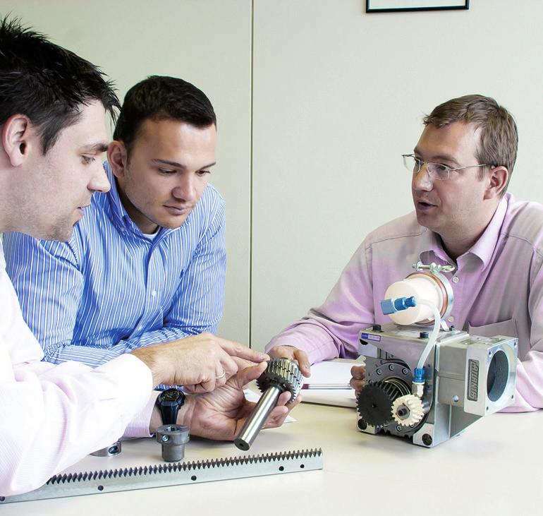
3 Tradition. Innovation. Progress. ATLANTA Drive Systems has offered convincing high-quality power transmission solutions for more than 80 years. As a medium-sized company we have specialized in the development, construction and production of high quality drive systems. ATLANTA customers are found in all areas of transmission engineering. The main focus however, lies in machine tool, woodworking machines, robotics and handlings, food machinery, packaging machines, boxing machines and special purpose machines. We are market leaders in high quality racks and define market trends. All components of our products are produced exclusively in our three modern plants in Bietigheim-Bissingen, Germany. We have 3 subsidiary companies and 23 agents in all industrialized countries to serve our customers all over the world. ISO 9001 : 2008 G 2 1/2015


4 Mitglied / Member 1/2015 G 3
5 Order Codes Examples Example High-Performance Gear Units High-Performance Gear Units Keyway Design a o = 80 mm Center Distance i = 19.5 Ratio High-Performance Gear Units Shrink-Disk Design a o = 80 mm Center Distance i = 19.5 Ratio Example Racks- for Continuous Linking Design Module With Holes Rack Length G 4 1/2015
6 Table of Contents Servo Gearboxes HT High-Torque Gear Units < 1' GA HP High-Performance Gear Units < 2' GB E Economy Gear Units < 5' GC B Basic Gear Units < 12' GD BG Servo-Bevel Gear Units < 6' GE Gear Units Calculation and Selection GF Pinion and Output Drive Shafts GG Shrink-Disk Clamping Sets GH Mounting Guide for Servo-Gear-Boxes and Servo Motors GI Racks and Pinions Helical Tooth System m = ZA Straight Tooth System m = 1 12 ZB Integrated Racks for Guides m = 2 4 ZC p = Rack and Pinion Drive Calculation and Selection ZD Lubrication System ZE Technical Aids ZF Agents Germany/Worldwide ZG 1/2015 G 5


7 Servo Gearbox Family ATLANTA Servo Drive Systems: Setting Standards for Technological Leadership The world s most extensive range of precision racks together with the complete family of servo gear units, provides an unmatched range of combinations to achieve the best solution to almost all possible applications. HT-Servo HP-Servo UHPR Ultra High Precision Rack Quality For each application the right solution High-precision machine tools with electrical preload Machine tools, lifting axis, dual-pinion systems Laser cutting machines Photo: Vansichen Lineairtechniek Belgium Driving and lifting axis of a robotic pallatizer G 6 1/2015


8 Servo Gearbox Family E-Servo BG-Servo B-Servo HPR High Precision Rack Quality PR Precision Rack Quality 8 BR Basic Rack Quality Wood, plastic, composite aluminum working machines Machine tools, water cutting machines, tube bending systems plasma cutting machines Portals, handling, lifting axis Linear axis Linear axis with low load, feed units for adjustment Lifting axis, handling, welding robots Woodworking machines, linear axis with high requirement for a smooth running Photo: Vansichen Lineairtechniek Belgium Linear axis with integrated lubrication system 1/2015 G 7


9 Servo Gearbox Family HT High-Torque Gear Units 150% Output Torque Backlash < 1 arcmin Highest Stiffness HP High-Performance Gear Units 100% Output Torque Backlash < 2 arcmin Highest Stiffness E Economy Gear Units 100% Output Torque Backlash < 5 arcmin Highest Stiffness B Basic Gear Units 90% Output Torque Backlash < 12 arcmin High Stiffness BG Servo-Bevel-Gear Units 100% Output Torque Backlash < 6 arcmin Highest Stiffness G 8 1/2015


10 NEW NEW NEW NEW NEW NEW Food Grade The New Servo Gear Units available with food grade lubricant Picture apple: atoss / Fotolia.com Manufacturing of machinery for the food industry must comply with a set of rules for general safety requirements, including cleaning and disinfection for hygiene. While drive technology is used in food processing machines and systems, it is not technically possible to eliminate 100% of the contact of food with lubricant, so food grade lubricants is a mandatory regulation in the food industry. If needed, we supply our Servo Gear Units filled with food grade lubricant for use it in the food industry. Due of the increasing demand, we have decided to offer all ATLANTA Servo Gear Units with food-grade lubricant. For this we have introduced a separate article number range, which you will find in our new catalog Servo Drive System edition 1/2015, chapter GA to GE. Example for ordering of ATLANTA servo gear units with food grade lubricant: Synthetic Oil Food Grade Oil HT High-Torque HP High-Performance E Economy B Basic Dmitry Vereshchagin / Fotolia.com / Fotolia.com G 9 1/2015
11 HT High-Torque Gear Units with <1' Adjustable Backlash Page HT High-Torque Gear Units with <1' Adjustable Backlash GA2 GA9 Center Distance 50 mm GA2 GA3 Center Distance 63 mm GA4 GA5 Center Distance 80 mm GA6 GA7 Center Distance 100 mm GA8 GA9 Couplings and Shrink-Disk Selection and Load Tables Short Description Mounting and Maintenance GA10 GA11 GA12 GA13 GA14 GA15 Gear Units Calculation and Selection GF1 GF3 Gear Units Accessories GG1 GG8 Motor Applications GI1 GI4 1/2015 Dimensions in mm GA 1
12 HT High-Torque Gear Units with <1' Adjustable Backlash Center Distance a o = 50 mm < 1 arcmin Fig. 1 Output shaft with interface according analog EN ISO A-40 Fig. 2 Output shaft for clamp connection Order Code J red 10-4 Fig. 1 Fig. 2 Ratio i kg m With food grade oil, order code xx / xx GA 2 Dimensions in mm 1/2015
13 HT High-Torque Gear Units with <1' Adjustable Backlash Motor Flange < 1 arcmin Center Distance a o = 50 mm Order Code D G7 k 1 r x y f 1 e G M , 95, 115 M4, M6, M M M M , 90, 115 M5, M5, M , 115 M6, M M M M M M M M M M M M M M M The order should contain gear box xx / xx and flange xx or 4xx. 1/2015 Dimensions in mm GA 3
14 HT High-Torque Gear Units with <1' Adjustable Backlash Center Distance a o = 63 mm < 1 arcmin Fig. 1 Output shaft with interface according analog EN ISO A-50 Fig. 2 Output shaft for clamp connection Order Code J red 10-4 Fig. 1 Fig. 2 Ratio i kg m With food grade oil, order code xx / xx GA 4 Dimensions in mm 1/2015
15 HT High-Torque Gear Units with <1' Adjustable Backlash Motor Flange < 1 arcmin Center Distance a o = 63 mm Order Code D G7 k 1 r x y f 1 e G M , 95, 115 M4, M6, M M M M , 90, 115 M5, M5, M , 115 M6, M M M M M M M M M M M M M M M The order should contain gear box xx / xx and flange xx or 4xx. 1/2015 Dimensions in mm GA 5
16 HT High-Torque Gear Units with <1' Adjustable Backlash Center Distance a o = 80 mm < 1 arcmin Fig. 1 Output shaft with interface according analog EN ISO A-63 Fig. 2 Output shaft for clamp connection Order Code J red 10-4 Fig. 1 Fig. 2 Ratio i kg m With food grade oil, order code xx / xx GA 6 Dimensions in mm 1/2015
17 HT High-Torque Gear Units with <1' Adjustable Backlash Motor Flange < 1 arcmin Center Distance a o = 80 mm Order Code D G7 k 1 r x y f 1 e G M M M M M M M M M M M M M The order should contain gear box xx / xx and flange xx. 1/2015 Dimensions in mm GA 7
18 HT High-Torque Gear Units with <1' Adjustable Backlash Center Distance a o = 100 mm < 1 arcmin Fig. 1 Output shaft with interface according analog EN ISO A-80 Fig. 2 Output shaft for clamp connection Order Code J red 10-4 Fig. 1 Fig. 2 Ratio i kg m With food grade oil, order code xx / xx GA 8 Dimensions in mm 1/2015

19 HT High-Torque Gear Units with <1' Adjustable Backlash Motor Flange < 1 arcmin Center Distance a o = 100 mm Order Code D G7 k 1 r x y f 1 e G M M M M M M M M M M M M M The order should contain gear box xx / xx and flange xx. 1/2015 Dimensions in mm GA 9
20 Connecting Elements Special Couplings for Motor/Gear Units, rigid model, nitrided, preassembled for motor shafts without key < 1 arcmin Bore on gear unit side low-clearance tooth-hub profile corresponding to DIN 5480 for push-fitting G l 1 l 2 d 1 Bore on motor side with locking elements as clamp connection D 1 D 2 d 2 DIN 5480 l 3 L 2 l 4 L 1 G Reference diameter for mounting Order Code Coupling 1) d 1 d 2 D 1 D 2 l 1 l 2 l 3 l 4 L 1 L 2 G x1.25x xM x1.25x xM x1.25x xM x1.25x xM x1.25x xM x1.25x xM x1.25x xM x1.25x xM x1.25x xM x1.25x xM x1.25x xM x1.25x xM x1.25x xM x1.25x xM x1.25x xM x1.25x xM x1.25x xM x1.25x xM x1.25x xM x1.25x xM /8" 38x1.25x xM x1.25x xM x1.25x xM x1.25x xM x1.25x xM x1.25x xM ) Spare part clamping element J red 10-4 kg m² Shrink-Disk Clamping Sets for Output Drive Shafts of gear series Supplied as complete set L 1 L 2 L 3 J red = J i 2 d 2 D l d 1 d 3 Order Code mm Nm d 1 d 2 d 3 D L 1 L 2 L 3 l G 10-4 kg m² x M x M x M x M GA 10 Dimensions in mm 1/2015
21 Selection and Load Table for HT High-Torque Gear Units The values in the tables are based upon wear or maximum flank load at 12,000 hours full load and on servo-operation. With continuous full-load operation it may be necessary to consider temperature limits! (Please ask us, if in doubt.) T 2max. = static torque to avoid tooth fracture, P 1 = driving power in kw, T 2 = output torque in Nm. < 1 arcmin Input Speed n 1 in rpm Order Code a 0 i T 2 max η P 1 T 2 P 1 T 2 P 1 T 2 P 1 T 2 P 1 T 2 P 1 T 2 P 1 T 2 at (mm) (kw) (Nm) (kw) (Nm) (kw) (Nm) (kw) (Nm) (kw) (Nm) (kw) (Nm) (kw) (Nm) * * * * On Request 1/2015 Dimensions in mm GA 11
22 Selection and Load Table for HT High-Torque Gear Units Gearing efficiency of servo worm gear units with driving worm and under full load. < 1 arcmin Efficiency η % Speed [rpm] Additional loads on output drive The data given are reference values. You should consider the values arising from the choice of the tooth system. It is assumed that the point of action of the force is the center of the shaft. In cases where additional axial forces occur, over and above high transverse forces, please ask for advice. l Fn Z Fa Z a Center Distance a (mm) Dimension center of casing EN ISO Clamp EN ISO Clamp EN ISO Clamp EN ISO Clamp to center of pinion Connect. Connect. Connect. Connect. l (mm) Max. additional load radial Fn z [N] axial Fa z [N] Only axial load Fa z [N] (Fn = 0) GA 12 Dimensions in mm 1/2015
23 HT High-Torque Gear Units Short Description ATLANTA HT High-Torque Worm Gear Units have been specially developed for use with the latest three-phase and DC servo-motors. Like all other components in this catalog, they are usually available ex stock or, at least, within a very short time. < 1 arcmin The following are typical features of our HT high-torque gear units: low-clearance gearing (backlash < 1'), adjustable up to 150% higher loading values casing of light metal for optimal heat dissipation robust bevel roller bearings for the output drive hollow shaft in O arrangement permitting greater additional forces. Center distances, gear ratios and tooth systems have been chosen in accordance with DIN 3975/76. The tooth shape was optimised so as to permit the adjustment of the clearance simply by changing the center distance by means of eccentric flanges. The use of ground, right-hand worms, a worm gear of special worm-gear bronze and dip-feed lubrication (synthetic special oil) ensures a high degree of efficiency and also smooth running in both directions and a long service life. The fully machined casing with its many fixing bores and tapped holes permits mounting in any position. The demand for an absolutely positive, and largely torsion-free connection between gear unit and output shaft, as it is especially important for intermittent operation, is fulfilled by our new gear-unit version with interface according to DIN EN ISO A as well as by our traditional version with shrink-disk coupling of the output shaft. The drive, i.e. the connection with the driving motor, is achieved with a special clutch. Its internal gearing, together with the barrelled profile of the driving shaft of our worm gear unit ensures transmission of the power with no free play. The use of annular spring elements firmly fixed to the motor shaft serves the same purpose. For the output drive you can choose from quite a number of output drive shafts with straight and helical tooth systems and various numbers of teeth. Apart from pinion shafts there is a multitude of gearwheels with different numbers of teeth from our gearwheel program which can be combined and used together with suitable special output drive shafts. In addition there is a large choice of gearwheels with helical tooth system for gear units with interface according to EN ISO A. For emergency stops, the maximum transmittable torque of the gear unit (see page GA-11) and shrink disk (see page GH-1) has to be checked. 1/2015 Dimensions in mm GA 13
24 Mounting and Maintenance HT High-Torque Gear Units < 1 arcmin Mounting Instructions Worm Gear Units Five mounting faces with sufficiently dimensioned tapped holes are provided for mounting in any position. In order to accommodate all supplementary forces (see page GA-12) we recommend mounting at the largest contact faces., i.e. at one of the two cap sides. Putting the worm shaft (input shaft) in a lateral or inferior position is ideal for lubrication. Mounting the shaft in a top position will reduce the driving capacity by about 10%. Coupling The coupling will be delivered pre-assembled. Before attaching it to the motor shaft all contact surfaces must be cleaned and protected by applying a thin oil film. A retaining ring inserted in the hub of the coupling locks it on the motor shaft preventing axial movement of the coupling. It may be necessary to insert this ring in the next recess. Recommended sequence: Slide the coupling onto the motor shaft until it clicks home (shoulder/retaining ring). Tighten the clamping screws slightly and check the coupling for true running. Tighten screws alternately crosswise using torque figures as shown in operation and maintenance instructions ensuring that the gap between coupling and contact face remains even. A final check of true running is recom mended at the applicable reference diameter! A mounting guide can be found on page GI-1 to GI-4 Motor Insert the motor with coupling mounted into the gear centering piece and bolt it to the gearbox. Output Pinion Shaft Unless the output pinion shaft comes already fully assembled, we recommend to proceed as follows: Clean pinion shaft and hollow shaft extension and then oil them. For the special output drive shaft we recommend tolerance h6 (DIN ISO286). the material must have a minimum yield point of 385 N/mm². A recalculation of the strength is necessary. Output Drive Pinion for Interface EN ISO A If the output pinion is not supplied already mounted, we recommend to proceed as follows: Clean the pinion and the gearbox interface, put on the pinion and tighten the screws (crosswise) to the proper torque acc. to table (suitable screws 12.9 are supplied with the cylindrical gears). GA 14 Dimensions in mm 1/2015
25 Mounting and Maintenance HT High-Torque Gear Units Output Drive Shaft for Shrink-Disk Connec tion Slide shrink disk onto the hollow shaft extension of the gear unit (please do not tighten the screws beforehand!).insert the output shaft from the desired side into the hollow shaft fully up to the stop. Make the transverse pressure connection by evenly tightening the clamping screws. Tighten the screws one after the other (not crosswise) in several passes to the torque indicated in the operation and maintenance instructions. < 1 arcmin Maintenance Adjustment of Circumferential Backlash The units are set up in the factory with a minimal amount of backlash. After prolonged usage, backlash may increase due to wear (reference value >15'). It can be adjusted by moving the eccentrically supported output shaft (= worm wheel). We recommend to proceed as follows: Unscrew the hexagon socket head screw of the two end caps without removing the caps in order to avoid oil leakage. Turn both caps towards the next higher number marked on the casing ensuring that they are both moved by the same amount. Check the backlash by turning the worm gear at least one complete revolution. If necessary, adjust further by another step. Evenly retighten the hexagon socket head screws alternately crosswise. An alteration of the gear center distance in relation to the overall operating conditions of the unit must be made up for by adjusting the attachment of the gear unit. Lubricant Change In the factory the gear units are filled with a synthetic lubricant and test run. They are delivered ready for use. A check of the lubricant level once a month - during the first weeks of operation more frequently - is recommended. Under normal load conditions and with single shift working it is recommended that the lubricant be changed every four years; with 2 or 3 shift working the lubricant should be changed annually. To do this, the unit must be emptied, flushed through and then refilled to the oil-level hole approximately in the middle of the gear unit using one of the lubricants recommended below. (Important: Synthetic lubricants must not be mixed with mineral oils.) For oil quantities see table. Center Distance Oil Quantity a = 50 mm 0.3 l a = 63 mm 0.5 l a = 80 mm 1.2 l a = 100 mm 2.0 l We recommend the following synthetic gear lubricant: Klübersynth GH Order Code: (1 liter) Alternative: SHELL Tivela S 220, BP Enersyn SG-XP 220, ARAL Degol GS 220 Degree to Protection Degree of protection: IP65/67 according to ISO (Corrosion has to be verified separately). 1/2015 Dimensions in mm GA 15
26 HP High-Performance Gear Units with <2' Adjustable Backlash Page HP High-Performance Gear Units with <2' Adjustable Backlash GB2 GB11 Center Distance 50 mm GB2 GB3 Center Distance 63 mm GB4 GB5 Center Distance 80 mm GB6 GB7 Center Distance 100 mm GB8 GB9 Center Distance 125 mm GB10 GB11 < 2 arcmin Couplings and Shrink-Disk GB12 Selection and Load Tables GB13 GB14 Short Description GB15 Mounting and Maintenance GB16 GB17 Gear Units Calculation and Selection GF1 GF3 Gear Units Accessories GG1 GG8 Motor Applications GI1 GI4 1/2015 Dimensions in mm GB 1
27 HP High-Performance Gear Units with <2' Adjustable Backlash Center Distance a o = 50 mm Fig. 1 Output shaft with key connection < 2 arcmin Fig. 2 Output shaft for clamp connection Order Code J red 10-4 Fig. 1 Fig. 2 Ratio i kg m With food grade oil, order code xx / xx GB 2 Dimensions in mm 1/2015
28 HP High-Performance Gear Units with <2' Adjustable Backlash Motor Flange < 2 arcmin Center Distance a o = 50 mm Order Code D G7 k 1 r x y f 1 e M , 95, 115 M4, M6, M M M M , 90, 115 M5, M5, M , 115 M6, M M M M M M M M M M M M M M M The order should contain gear box xx / xx and flange xx or 4xx. 1/2015 Dimensions in mm GB 3
29 HP High-Performance Gear Units with <2' Adjustable Backlash Center Distance a o = 63 mm Fig. 1 Output shaft with key connection < 2 arcmin Fig. 2 Output shaft for clamp connection Order Code J red 10-4 Fig. 1 Fig. 2 Ratio i kg m With food grade oil, order code xx / xx GB 4 Dimensions in mm 1/2015
30 HP High-Performance Gear Units with <2' Adjustable Backlash Motor Flange < 2 arcmin Center Distance a o = 63 mm Order Code D G7 k 1 r x y f 1 e G M , 95, 115 M4, M6, M M M M , 90, 115 M5, M5, M , 115 M6, M M M M M M M M M M M M M M M The order should contain gear box xx / xx and flange xx or 4xx. 1/2015 Dimensions in mm GB 5
31 HP High-Performance Gear Units with <2' Adjustable Backlash Center Distance a o = 80 mm Fig. 1 Output shaft with key connection < 2 arcmin Fig. 2 Output shaft for clamp connection Order Code J red 10-4 Fig. 1 Fig. 2 Ratio i kg m With food grade oil, order code xx / xx GB 6 Dimensions in mm 1/2015
32 HP High-Performance Gear Units with <2' Adjustable Backlash Motor Flange < 2 arcmin Center Distance a o = 80 mm Order Code D G7 k 1 r x y f 1 e G M M M M M M M M M M M M M The order should contain gear box xx / xx and flange xx. 1/2015 Dimensions in mm GB 7
33 HP High-Performance Gear Units with <2' Adjustable Backlash Center Distance a o = 100 mm Fig. 1 Output shaft with key connection < 2 arcmin Fig. 2 Output shaft for clamp connection Order Code J red 10-4 Fig. 1 Fig. 2 Ratio i kg m With food grade oil, order code xx / xx GB 8 Dimensions in mm 1/2015
34 HP High-Performance Gear Units with <2' Adjustable Backlash Motor Flange < 2 arcmin Center Distance a o = 100 mm Order Code D G7 k 1 r x y f 1 e G M M M M M M M M M M M M M The order should contain gear box xx / xx and flange xx. 1/2015 Dimensions in mm GB 9
35 HP High-Performance Gear Units with <2' Adjustable Backlash Center Distance a o = 125 mm < 2 arcmin r M16x Ø160 H7 f 1 G x y f G D 37.7 h8 M16x ± e k DIN 5480 W38x1,25x29 18 P8 Fig. 1 Output shaft with key connection r M16x h8 M16x ± f 1 G 26 e Ø160 H8 x f k 280 DIN 5480 W38x1,25x29 60 G6 80 h8 Fig. 2 Output shaft for clamp connection GB 10 Dimensions in mm 1/2015
36 HP High-Performance Gear Units with <2' Adjustable Backlash Center Distance a o = 125 mm Order Code Fig.1 Fig. 2 Ratio i D G7 k r x y f 1 e G J red 10-4 kg m² M M < 2 arcmin Other center distances and ratios available on request. 2/2015 Dimensions in mm GB 11
37 Connecting Elements Special Couplings for Motor/Gear Units, rigid model, nitrided, preassembled for motor shafts without key < 2 arcmin Bore on gear unit side low-clearance tooth-hub profile corresponding to DIN 5480 for push-fitting G l 1 l 2 d 1 Bore on motor side with locking elements as clamp connection D 1 D 2 l 3 L 2 l 4 G d 2 DIN 5480 L 1 Reference diameter for mounting Order Code Coupling 1) d 1 d 2 D 1 D 2 l 1 l 2 l 3 l 4 L 1 L 2 G J red 10-4 kg m² x1.25x xM x1.25x xM x1.25x xM x1.25x xM x1.25x xM x1.25x xM x1.25x xM x1.25x xM x1.25x xM x1.25x xM x1.25x xM x1.25x xM x1.25x xM x1.25x xM x1.25x xM x1.25x xM x1.25x xM x1.25x xM x1.25x xM x1.25x xM /8" 38x1.25x xM x1.25x xM x1.25x xM x1.25x xM x1.25x xM x1.25x xM ) Spare part clamping element Shrink-Disk Clamping Sets for Output Drive Shafts of gear series Supplied as complete set L 1 L 2 L 3 J red = J i 2 d 2 D l d 1 d 3 a 0 T 2 max Order Code mm Nm d 1 d 2 d 3 D L 1 L 2 L 3 l G J 10-4 kg m² x M x M x M x M x M GB 12 Dimensions in mm 1/2015
38 Selection and Load Table for HP High-Performance Gear Units The values in the tables are based upon wear or maximum flank load at 12,000 hours full load and on servo-operation. With continuous full-load operation it may be necessary to consider temperature limits! (Please ask us, if in doubt.) T 2max. = static torque to avoid tooth fracture, P 1 = driving power in kw, T 2 = output torque in Nm < 2 arcmin Input Speed n 1 in rpm Order Code a 0 i T 2 max η P 1 T 2 P 1 T 2 P 1 T 2 P 1 T 2 P 1 T 2 P 1 T 2 P 1 T 2 at (mm) (kw) (Nm) (kw) (Nm) (kw) (Nm) (kw) (Nm) (kw) (Nm) (kw) (Nm) (kw) (Nm) * * * _ _ ) _ _ _ _ _ _ _ _ _ _ _ _ * On request 1) Power and driving torque corresponding to max. input speed of 2800 rpm 1/2015 Dimensions in mm GB 13
39 Selection and Load Table for HP High-Performance Gear Units Gearing efficiency of servo worm gear units with driving worm and under full load. < 2 arcmin Efficiency η % Speed [rpm] Additional loads on output drive The data given are reference values. You should consider the values arising from the choice of the tooth system. It is assumed that the point of action of the force is the center of the shaft. In cases where additional axial forces occur, over and above high transverse forces, please ask for advice. l Fn Z Fa Z a Center Distance a (mm) Dimension center of casing to center of pinion l (mm) Max. additional load radial Fn z [N] axial Fa z [N] Only axial load Fa z [N] (Fn = 0) GB 14 Dimensions in mm 1/2015
40 HP High-Performance Gear Units Short Description ATLANTA HP high-performance worm gear units have been specially developed for use with the latest three-phase and DC servo-motors. Like all other components in this catalog, they are usually available ex stock or, at least, within a very short time. The following are typical features of our HP High-Performance Gear Units: low-clearance gearing (backlash < 2'), adjustable up to 70 % higher loading values casing of light metal for optimal heat dissipation robust bevel roller bearings for the output drive hollow shaft, permitting greater additional forces. < 2 arcmin Center distances, gear ratios and tooth systems have been chosen in accordance with DIN 3975/76. The tooth shape was optimised so as to permit the adjustment of the clearance simply by changing the center distance by means of eccentric flanges. The use of ground, right-hand worms, a worm gear of special worm-gear bronze and dip-feed lubrication (synthetic special oil) ensures a high degree of efficiency and also smooth running in both directions and a long service life. The fully machined casing with its many fixing bores and tapped holes permits mounting in any position. The demand for an absolutely positive, and largely torsion-free connection between gear unit and output shaft, as it is especially important for intermittent operation, is fulfilled by our new gear units using shrink-disk coupling with the output drive shaft. The drive, i.e. the connection with the driving motor, is achieved with a special clutch. Its internal gearing, together with the barrelled profile of the driving shaft of our worm gear unit ensures transmission of the power with no free play. The use of annular spring elements firmly fixed to the motor shaft serves the same purpose. For the output drive you can choose from quite a number of output drive shafts with straight and helical tooth systems and various numbers of teeth. Apart from pinion shafts there is a multitude of gearwheels with different numbers of teeth from our gearwheel program which can be combined and used together with suitable special output drive shafts.the whole range of drive shafts, like our gear units, is of course available for key and shrink-fit connection. Racks ideally supplement our programme of standard elements for servo drive units. Our off-the shelf programme ranges from relatively simple, soft racks through hardened racks available with straight tooth system or with helical tooth system for smooth running, to the fully ground, low-tolerance types. For emergency stops, the maximum transmittable torque of the gear unit (see page GB-13) and shrink disk (see page GH-1) has to be checked. The output keyway has to be calculated separately. 1/2015 Dimensions in mm GB 15
41 Mounting and Maintenance HP High-Performance Gear Units < 2 arcmin Mounting Instructions Worm Gear Units Five mounting faces with sufficiently dimensioned tapped holes are provided for mounting in any position. In order to accommodate all supplementary forces (see page GB-14) we recommend mounting at the largest contact faces., i.e. at one of the two cap sides. Putting the worm shaft (input shaft) in a lateral or inferior position is ideal for lubrication. Mounting the shaft in a top position will reduce the driving capacity by about 10 %. Coupling The coupling will be delivered pre-assembled. Before attaching it to the motor shaft all contact surfaces must be cleaned and protected by applying a thin oil film. A retaining ring inserted in the hub of the coupling locks it on the motor shaft preventing axial movement of the coupling. It may be necessary to insert this ring in the next recess. Recommended sequence: Slide the coupling onto the motor shaft until it clicks home (shoulder/retaining ring). Tighten the clamping screws slightly and check the coupling for true running. Tighten screws alternately crosswise using torque figures as shown in the operation and maintenance instructions ensuring that the gap between coupling and contact face remains even. A final check of true running is recom mended at the applicable reference diameter! A mounting guide can be found on page GI-1 to GI-4 Motor Insert the motor with coupling mounted into the gear centering piece and bolt it to the gearbox. Output Pinion Shaft Unless the output pinion shaft comes already fully assembled, we recommend to proceed as follows: Clean pinion shaft and hollow shaft extension and then oil them. For the special output drive shaft we recommend tolerance h6 (DIN ISO286). the material must have a minimum yield point of 385 N/mm². A recalculation of the strength is necessary. Output Drive Shaft for Shrink-Disk Connec tion Slide shrink disk onto the hollow shaft extension of the gear unit (please do not tighten the screws beforehand!). Insert the output shaft from the desired side into the hollow shaft fully up to the stop. Make the transverse pressure connection by evenly tightening the clamping screws. Tighten the screws one after the other (not crosswise) in several passes to the torque indicated in the operation and maintenance instructions. GB 16 Dimensions in mm 1/2015
42 Mounting and Maintenance HP High-Performance Gear Units Output Drive Shaft for Key Connection - The retaining ring, the disk and the screw supplied with the output drive shaft serve for locking the output shaft in axial direction. For this purpose insert the retaining ring in the applicable recess of the hollow shaft and slide the output drive shaft from the desired side into the hollow shaft up to the stop. Disk and screw are screwed to the output shaft from the other side of the gear unit. The retaining ring must be clamped between disk and pinion shaft. Maintenance Adjustment of Circumferential Backlash The units are set up in the factory with a minimal amount of backlash. After prolonged usage, backlash may increase due to wear (reference value >15'). It can be adjusted by moving the eccentrically supported output shaft (= worm wheel). < 2 arcmin We recommend to proceed as follows: Unscrew the hexagon socket head screw of the two end caps without removing the caps in order to avoid oil leakage. Turn both caps towards the next higher number marked on the casing ensuring that they are both moved by the same amount. Check the backlash by turning the worm gear at least one complete revolution. If necessary, adjust further by another step. Evenly retighten the hexagon socket head screws alternately crosswise. An alteration of the gear center distance in relation to the overall operating conditions of the unit must be made up for by adjusting the attachment of the gear unit. Lubricant Change In the factory the gear units are filled with a synthetic lubricant and test run. They are delivered ready for use. A check of the lubricant level once a month - during the first weeks of operation more frequently - is recommended. Under normal load conditions and with single shift working it is recommended that the lubricant be changed every four years, with 2 or 3 shift working the lubricant should be changed annually. To do this, the unit must be emptied, flushed through and then refilled to the oil-level hole approximately in the middle of the gear unit using one of the lubricants recommended below. (Important: Synthetic lubricants must not be mixed with mineral oils.) For oil quantities see table. Center Distance Oil Quantity a = 50 mm 0.3 l a = 63 mm 0.5 l a = 80 mm 1.2 l a = 100 mm 2.0 l a = 125 mm 4.0 l We recommend the following synthetic gear lubricant: Klübersynth GH Order code: (1 liter) Alternative: SHELL Tivela S 220, BP Enersyn SG-XP 220, ARAL Degol GS 220 Degree to Protection Degree of protection: IP65/67 according to DIN ISO (Corrosion has to be verified separately). 1/2015 Dimensions in mm GB 17
43 E Economy Gear Units with <5' Backlash E Economy Gear Units with <5' Backlash GC2 GC9 Page Center Distance 32 mm GC2 GC3 Center Distance 50 mm GC4 GC5 Center Distance 63 mm GC6 GC7 Center Distance 80 mm GC8 GC9 Center Distance 100 mm GC10 GC11 < 5 arcmin Couplings and Shrink-Disk GC12 GC13 Selection and Load Tables GC14 GC15 Short Description GC16 Mounting and Maintenance GC17 GC18 Gear Units Calculation and Selection GF1 GF3 Gear Units Accessories GG1 GG8 Motor Applications GI5 GI9 1/2015 Dimensions in mm GC 1
44 E Economy Gear Units with <5' Backlash Center Distance a o = 32 mm Fig. 1 Output shaft with key connection < 5 arcmin Fig. 2 Output shaft for clamp connection Order Code J red 10-4 Fig. 1 Fig. 2 Ratio i kg m With food grade oil, order code xx / xx GC 2 Dimensions in mm 1/2015
45 E Economy Gear Units with <5' Backlash Motor Flange < 5 arcmin Center Distance a o = 32 mm Order Code D G7 k 1 r x y f 1 e G M M M M M M The order should contain gear box xx / xx and flange xx. 1/2015 Dimensions in mm GC 3
46 E Economy Gear Units with <5' Backlash Center Distance a o = 50 mm Fig. 1 Output shaft with key connection < 5 arcmin Fig. 2 Output shaft for clamp connection Order Code J red 10-4 Fig. 1 Fig. 2 Ratio i kg m With food grade oil, order code xx / xx GC 4 Dimensions in mm 1/2015
47 E Economy Gear Units with <5' Backlash Motor Flange < 5 arcmin Center Distance a o = 50 mm Order Code D G7 k 1 r x y f 1 e G M , 95, 115 M4, M6, M M M M , 90, 115 M5, M5, M , 115 M6, M M M M M M M M M M M M M M M The order should contain gear box xx / xx and flange xx or 4xx. 1/2015 Dimensions in mm GC 5
48 E Economy Gear Units with <5' Backlash Center Distance a o = 63 mm Fig. 1 Output shaft with key connection < 5 arcmin Fig. 2 Output shaft for clamp connection Order Code J red 10-4 Fig. 1 Fig. 2 Ratio i kg m With food grade oil, order code xx / xx GC 6 Dimensions in mm 1/2015
49 E Economy Gear Units with <5' Backlash Motor Flange < 5 arcmin Center Distance a o = 63 mm Order Code D G7 k 1 r x y f 1 e G M , 95, 115 M4, M6, M M M M , 90, 115 M5, M5, M , 115 M6, M M M M M M M M M M M M M M M The order should contain gear box xx / xx and flange xx or 4xx. 1/2015 Dimensions in mm GC 7
50 E Economy Gear Units with <5' Backlash Center Distance a o = 80 mm Fig. 1 Output shaft with key connection < 5 arcmin Fig. 2 Output shaft for clamp connection Order Code J red 10-4 Fig. 1 Fig. 2 Ratio i kg m With food grade oil, order code xx / xx GC 8 Dimensions in mm 1/2015
51 E Economy Gear Units with <5' Backlash Motor Flange < 5 arcmin Center Distance a o = 80 mm Order Code D G7 k 1 r x y f 1 e G M M M M M M M M M M M M M The order should contain gear box xx / xx and flange xx. 1/2015 Dimensions in mm GC 9
52 E Economy Gear Units with <5' Backlash Center Distance a o = 100 mm Fig. 1 Output shaft with key connection < 5 arcmin Fig. 2 Output shaft for clamp connection Order Code J red 10-4 Fig. 1 Fig. 2 Ratio i kg m With food grade oil, order code xx / xx GC 10 Dimensions in mm 1/2015

53 E Economy Gear Units with <5' Backlash Motor Flange < 5 arcmin Center Distance a o = 100 mm Order Code D G7 k 1 r x y f 1 e G M M M M M M M M M M M M M The order should contain gear box xx / xx and flange xx. 1/2015 Dimensions in mm GC 11
54 Connecting Elements Special Couplings for Motor/Gear Units, rigid model, nitrided, preassembled for motor shafts without key Bore on gear unit side low-clearance tooth-hub profile corresponding to DIN 5480 for push-fitting Reference diameter for the mounting < 5 arcmin Order Code Coupling d 1 d 2 D 1 D 2 L 1 L 3 R 1 G L 2 Couplings on page GA-10 can be used as well. J red 10-4 kg m² x1.25x M x1.25x M x1.25x M x1.25x M x1.25x M x1.25x M x1.25x M x1.25x M x1.25x M x1.25x M x1.25x M x1.25x M x1.25x M x1.25x M x1.25x M x1.25x M x1.25x M x1.25x M x1.25x M x1.25x M x1.25x M x1.25x M x1.25x M x1.25x M x1.25x M x1.25x M x1.25x M x1.25x M x1.25x M x1.25x M x1.25x M x1.25x M x1.25x M x1.25x M x1.25x M x1.25x M x1.25x M x1.25x M x1.25x M x1.25x M x1.25x M x1.25x M x1.25x M GC 12 Dimensions in mm 1/2015
55 Connecting Elements Shrink-Disk Clamping Sets for Output Drive Shafts of gear series Supplied as complete set L 1 L 2 L 3 J red = J i 2 d 2 D l d 1 d 3 < 5 arcmin Order Code mm Nm d 1 d 2 d 3 D L 1 L 2 L 3 l G J 10-4 kg m² x M x M x M x M x M /2015 Dimensions in mm GC 13
56 Selection and Load Table for E Economy Gear Units The values in the tables are based upon wear or maximum flank load at 12,000 hours full load and on servo-operation. With continuous full-load operation it may be necessary to consider temperature limits! (Please ask us, if in doubt.) T 2max. = static torque to avoid tooth fracture, P 1 = driving power in kw, T 2 = output torque in Nm. < 5 arcmin Input Speed n 1 in rpm Order Code a 0 i T 2 max η P 1 T 2 P 1 T 2 P 1 T 2 P 1 T 2 P 1 T 2 P 1 T 2 P 1 T 2 at (mm) (kw) (Nm) (kw) (Nm) (kw) (Nm) (kw) (Nm) (kw) (Nm) (kw) (Nm) (kw) (Nm) * * * * * On Request GC 14 Dimensions in mm 1/2015
57 Selection and Load Table for E Economy Gear Units Gearing efficiency of servo worm gear units with driving worm and under full load. Efficiency η % < 5 arcmin Speed [rpm] Additional loads on output drive The data given are reference values. You should consider the values arising from the choice of the tooth system. It is assumed that the point of action of the force is the center of the shaft. In cases where additional axial forces occur, over and above high transverse forces, please ask for advice. l Fn Z Fa Z a Center Distance a (mm) Dimension center of casing to center of pinion l (mm) Max. additional load radial Fn z [N] axial Fa z [N] /2015 Dimensions in mm GC 15
58 E Economy Gear Units Short Description ATLANTA E-servo worm gear units have been specially developed for use with the latest three-phase and DC servo-motors. Like all other components in this catalog, they are usually available ex stock or, at least, within a very short time. The following are typical features of our E-servo gear units: < 5 arcmin the same dimensions as our HP Servo-Worm Gear Units low-clearance gearing (backlash < 5'), the same load values as our servo worm gear units serie 58 casing of light metal for optimal heat dissipation robust bearings for the output drive hollow shaft, permitting greater additional forces. Center distances, gear ratios and tooth systems have been chosen in accordance with DIN 3975/76. The use of ground, right-hand worms, a worm gear of special worm-gear bronze and dip-feed lubrication (synthetic special oil) ensures a high degree of efficiency and also smooth running in both directions and a long service life. The casing with its many fixing bores and tapped holes permits mounting in any position. The drive, i.e. the connection with the driving motor, is achieved with a special clutch. Its internal gearing, together with the barrelled profile of the driving shaft of our worm gear unit ensures transmission of the power with no free play. For the output drive you can choose from quite a number of output drive shafts with straight and helical tooth systems and various numbers of teeth. Apart from pinion shafts there is a multitude of gearwheels with different numbers of teeth from our S & L gearwheel program which can be combined and used together with suitable special output drive shafts. For emergency stops, the maximum transmittable torque of the gear unit (see page GC-14) and shrink disk (see page GH-1) has to be checked. The output keyway has to be calculated separately. GC 16 Dimensions in mm 1/2015
59 Mounting and Maintenance E Economy Gear Units Mounting Instructions Worm Gear Units Five mounting faces with sufficiently dimensioned tapped holes are provided for mounting in any position. In order to accommodate all supplementary forces (see page GC-15) we recommend mounting at the largest contact faces., i.e. at one of the two cap sides. Putting the worm shaft (input shaft) in a lateral or inferior position is ideal for lubrication. Mounting the shaft in a top position will reduce the driving capacity by about 10 %. Coupling The coupling is supplied pre-assembled. All contact surfaces must be cleaned and protected by a thin oil film before attaching it to the motor shaft. An important dimension for mounting is the value X1 (compare pages GI 5 to GI 9). Recommended procedure: Carefully clean the contact surfaces and protect them with a thin oil film. Place the coupling onto the motor shaft at the distance given by the measurement X1 (see pages GI 5 to GI 9); a depth gauge is helpful for determining the measurement. Slightly tighten the clamping screws and check the clutch for true running Tighten the screws alternately and uniformly. The correct tightening torque can be seen from the operation and maintenance instructions. The gap in the coupling must be equally wide on both sides. It is recommended to make another final check for true running at the appropriate reference diameter! < 5 arcmin A mounting guide can be found on page GI-5 to GI-9 Motor Insert the motor with coupling mounted into the gear centering piece and bolt it to the gearbox. Output Pinion Shaft Unless the output pinion shaft comes already fully assembled, we recommend to proceed as follows: Clean pinion shaft and hollow shaft extension and then oil them. For the special output drive shaft we recommend tolerance h6 (DIN ISO286). the material must have a minimum yield point of 385 N/mm². A recalculation of the strength is necessary. Output Drive Shaft for Shrink-Disk Connec tion Slide shrink disk onto the hollow shaft extension of the gear unit (please do not tighten the screws beforehand!).insert the output shaft from the desired side into the hollow shaft fully up to the stop. Make the transverse pressure connection by evenly tightening the clamping screws. Tighten the screws one after the other (not crosswise) in several passes to the torque indicated in the operation and maintenance instructions. Output Drive Shaft for Key Connection The retaining ring, the disk and the screw supplied with the output drive shaft serve for locking the output shaft in axial direction. For this purpose insert the retaining ring in the applicable recess of the hollow shaft and slide the output drive shaft from the desired side into the hollow shaft up to the stop. Disk and screw are screwed to the output shaft from the other side of the gear unit. The retaining ring must be clamped between disk and pinion shaft. 1/2015 Dimensions in mm GC 17
60 Mounting and Maintenance E Economy Gear Units Maintenance < 5 arcmin Lubricant Change ATLANTA servo worm-gear units are filled with synthetic polyglycol oil. Under the following conditions this means lifetime lubri cation: The layout of the gear unit is made strictly in conformance with the guidelines specified in the ATLANTA catalog and the gear unit is operated exclusively within the permissible characteristic values and limits. The operator checks the gear unit regularly (every 4 weeks) for oil leakage. The surface temperature does not exceed max. 80 C. Experience has shown that this temperature is not reached with servo-operation (intermittent operation). In the case of an operation with mainly low input speeds (circumferential speed of the worm v < 0.5 m/s) we recommend to change the lubricant every two years. Center Distance Oil Quantity a = 32 mm 0.07 l a = 50 mm 0.40 l a = 63 mm 0.70 l a = 80 mm 1.70 l a = 100 mm 2.00 l We recommend the following synthetic gear lubricant: Klübersynth GH Order code: (1 liter) Alternative: SHELL Tivela S 220, BP Enersyn SG-XP 220, ARAL Degol GS 220 Degree of Protection Degree of protection: IP65/67 according to ISO (Corrosion has to be verified separately). GC 18 Dimensions in mm 1/2015
61 B Basic Gear Units with <12' Backlash B Basic Gear Units with <12' Backlash GD2 GD7 Center Distance 50 mm GD2 GD3 Center Distance 63 mm GD6 GD7 Page Couplings and Shrink-Disk GD12 Selection and Load Tables GD14 GD15 Short Description GD16 < 12 arcmin Mounting and Maintenance GD17 GD18 Gear Units Calculation and Selection GF1 GF3 Gear Units Accessories GG1 GG9 Mounting Guide for Servo Gears GI5 GI9 1/2015 Dimensions in mm GD 1
62 B Basic Gear Units with <12' Backlash Center Distance a o = 50 mm Fig. 1 Output shaft with key connection < 12 arcmin Fig. 2 Output shaft for clamp connection Order Code J red 10-4 Fig. 1 Fig. 2 Ratio i kg m With food grade oil, order code xx / xx GD 4 Dimensions in mm 1/2015
63 B Basic Gear Units with <12' Backlash Motor Flange < 12 arcmin Center Distance a o = 50 mm Order Code D G7 k 1 r x y f 1 e G M , 95, 115 M4, M6, M M M M , 90, 115 M5, M5, M , 115 M6, M M M M M M M M M M M M M M M The order should contain gear box xx / xx and flange xx or 4xx. 1/2015 Dimensions in mm GD 5
64 B Basic Gear Units with <12' Backlash Center Distance a o = 63 mm Fig. 1 Output shaft with key connection < 12 arcmin Fig. 2 Output shaft for clamp connection Order Code J red 10-4 Fig. 1 Fig. 2 Ratio i kg m With food grade oil, order code xx / xx GD 6 Dimensions in mm 1/2015

65 B Basic Gear Units with <12' Backlash Motor Flange < 12 arcmin Center Distance a o = 63 mm Order Code D G7 k 1 r x y f 1 e G M , 95, 115 M4, M6, M M M M , 90, 115 M5, M5, M , 115 M6, M M M M M M M M M M M M M M M The order should contain gear box xx / xx and flange xx or 4xx. 1/2015 Dimensions in mm GD 7
66 Connecting Elements Special Couplings for Motor/Gear Units, rigid model, nitrided, preassembled for motor shafts without key Bore on gear unit side low-clearance tooth-hub profile corresponding to DIN 5480 for push-fitting Reference diameter for the mounting < 12 arcmin Order Code Coupling d 1 d 2 D 1 D 2 L 1 L 3 R 1 G L x1.25x M x1.25x M x1.25x M x1.25x M x1.25x M x1.25x M x1.25x M x1.25x M x1.25x M x1.25x M x1.25x M x1.25x M x1.25x M x1.25x M x1.25x M x1.25x M x1.25x M x1.25x M x1.25x M x1.25x M x1.25x M x1.25x M x1.25x M x1.25x M x1.25x M x1.25x M x1.25x M x1.25x M x1.25x M x1.25x M x1.25x M Couplings on page GA-10 can be used as well. J red 10-4 kg m² GD 12 Dimensions in mm 1/2015
67 Connecting Elements Shrink-Disk Clamping Sets for Output Drive Shafts of gear series Supplied as complete set L 1 L 2 L 3 J red = J i 2 d 2 D l d 1 d 3 Order Code mm Nm d 1 d 2 d 3 D L 1 L 2 L 3 l G J 10-4 kg m² < 12 arcmin x M x M /2015 Dimensions in mm GD 13
68 Selection and Load Table for B Basic Gear Units The values in the tables are based upon wear or maximum flank load at 12,000 hours full load and on servo-operation. With continuous full-load operation it may be necessary to consider temperature limits! (Please ask us, if in doubt.) T 2max. = static torque to avoid tooth fracture, P 1 = driving power in kw, T 2 = output torque in Nm. < 12 arcmin Input Speed n 1 in rpm Order Code a 0 i T 2 max η P 1 T 2 P 1 T 2 P 1 T 2 P 1 T 2 P 1 T 2 P 1 T 2 P 1 T 2 at (mm) (kw) (Nm) (kw) (Nm) (kw) (Nm) (kw) (Nm) (kw) (Nm) (kw) (Nm) (kw) (Nm) * * * On Request GD 14 Dimensions in mm 1/2015
69 Selection and Load Table for B Basic Gear Units Gearing efficiency of servo worm gear units with driving worm and under full load. Efficiency η % < 12 arcmin Speed [rpm] Additional loads on output drive The data given are reference values. You should consider the values arising from the choice of the tooth system. It is assumed that the point of action of the force is the center of the shaft. In cases where additional axial forces occur, over and above high transverse forces, please ask for advice. l Fn Z Fa Z a Center Distance a (mm) Dimensions center of casing to center of pinion l (mm) Max. additional load radial Fn z [N] axial Fa z [N] /2015 Dimensions in mm GD 15
70 B Basic Gear Units Short Description ATLANTA B-servo worm gear units have been specially developed for use with the latest three-phase and DC servo-motors. Like all other components in this catalog, they are usually available ex stock or, at least, within a very short time. The following are typical features of our B-servo gear units: the same dimensions as our servo worm gear units serie 59 low-clearance gearing (backlash < 12'), casing of light metal for optimal heat dissipation robust bearings for the output drive hollow shaft, permitting additional forces. Center distances, gear ratios and tooth systems have been chosen in accordance with DIN 3975/76. < 12 arcmin The use of ground, right-hand worms, a worm gear of special worm-gear bronze and dip-feed lubrication (synthetic special oil) ensures a high degree of efficiency and also smooth running in both directions and a long service life. The casing with its many fixing bores and tapped holes permits mounting in any position. The drive, i.e. the connection with the driving motor, is achieved with a special clutch. Its internal gearing, together with the barrelled profile of the driving shaft of our worm gear unit ensures transmission of the power with no free play. For the output drive you can choose from quite a number of output drive shafts with straight and helical tooth systems and various numbers of teeth. Apart from pinion shafts there is a multitude of gearwheels with different numbers of teeth from our S & L gearwheel program which can be combined and used together with suitable special output drive shafts. For emergency stops, the maximum transmittable torque of the gear unit (see page GD-14) and shrink disk (see page GH-1) has to be checked. The output keyway has to be calculated separately. GD 16 Dimensions in mm 1/2015
71 Mounting and Maintenance B Basic Gear Units Mounting Instructions Worm Gear Units Five mounting faces with sufficiently dimensioned tapped holes are provided for mounting in any position. In order to accommodate all supplementary forces (see page GD-15) we recommend mounting at the largest contact faces., i.e. at one of the two cap sides. Putting the worm shaft (input shaft) in a lateral or inferior position is ideal for lubrication. Mounting the shaft in a top position will reduce the driving capacity by about 10 %. Coupling The coupling is supplied pre-assembled. All contact surfaces must be cleaned and protected by a thin oil film before attaching it to the motor shaft. An important dimension for mounting is the value X1 (compare pages GI 5 to GI 9). Recommended procedure: Carefully clean the contact surfaces and protect them with a thin oil film. Place the coupling onto the motor shaft at the distance given by the measurement X1 (see pages GI 5 to GI 9); a depth gauge is helpful for determining the measurement. Slightly tighten the clamping screws and check the clutch for true running Tighten the screws alternately and uniformly. The correct tightening torque can be seen from the operation and maintenance instructions. The gap in the coupling must be equally wide on both sides. It is recommended to make another final check for true running at the appropriate reference diameter! < 12 arcmin A mounting guide can be found on page GI-5 to GI-9. Motor Insert the motor with coupling mounted into the gear centering piece and bolt it to the gearbox. Output Pinion Shaft Unless the output pinion shaft comes already fully assembled, we recommend to proceed as follows: Clean pinion shaft and hollow shaft extension and then oil them. For the special output drive shaft we recommend tolerance h6 (DIN ISO286). the material must have a minimum yield point of 385 N/mm². A recalculation of the strength is necessary. Output Drive Shaft for Shrink-Disk Connec tion Slide shrink disk onto the hollow shaft extension of the gear unit (please do not tighten the screws beforehand!).insert the output shaft from the desired side into the hollow shaft fully up to the stop. Make the transverse pressure connection by evenly tightening the clamping screws. Tighten the screws one after the other (not crosswise) in several passes to the torque indicated in the operation and maintenance instructions. Output Drive Shaft for Key Connection The retaining ring, the disk and the screw supplied with the output drive shaft serve for locking the output shaft in axial direction. For this purpose insert the retaining ring in the applicable recess of the hollow shaft and slide the output drive shaft from the desired side into the hollow shaft up to the stop. Disk and screw are screwed to the output shaft from the other side of the gear unit. The retaining ring must be clamped between disk and pinion shaft. 1/2015 Dimensions in mm GD 17
72 Mounting and Maintenance B Basic Gear Units Maintenance Lubricant Change ATLANTA B-servo-worm-gear units are filled with synthetic polyglycol oil. Under the following conditions this is a lifetime lubrication: The layout of the gear unit is made strictly in conformance with the guidelines specified in the ATLANTA catalog and the gear unit is operated exclusively within the permissible characteristic values and limits. The operator checks the gear unit regularly (every 4 weeks) for oil leakage. The surface temperature does not exceed max. 80 C. Experience has shown that this temperature is not reached with servo-operation (intermittent operation). In the case of an operation with mainly low input speeds (circumferential speed of the worm v < 0.5 m/s) we recommend to change the lubricant every two years. < 12 arcmin Center Distance Oil Quantity a = 50 mm 0.25 l a = 63 mm 0.60 l We recommend the following synthetic gear lubricant: Klübersynth GH Order code: (1 liter) Alternative: SHELL Tivela S 220, BP Enersyn SG-XP 220, ARAL Degol GS 220 Degree of Protection Degree of protection: IP65/67 according to ISO (Corrosion has to be verified separately). GD 18 Dimensions in mm 1/2015
73 BG Bevel-Gear Units with <6' Backlash BG Bevel-Gear Units with <6' Backlash Page Size 50 GE2 GE3 Size 63 GE4 GE5 Size 80 GE6 GE7 Couplings and Shrink-Disks GE8 GE9 Selection and Load Tables Short Description GE10 GE11 Mounting and Maintenance GE12 GE13 Motor Applications GI5 GI9 < 6 arcmin 1/2015 Dimensions in mm GE 1
74 BG Bevel-Gear Units with <6' Backlash Key Connection Size BG 50 5 Mounting Surfaces < 6 arcmin DIN 5480 W15x1.25x10 Fig. 1 Output shaft with key connection G6 * Mounting disk for key connection Shrink-Disk Connection Size BG 50 5 Mounting Surfaces DIN 5480 W15x1,25x10 G6 Fig. 2 Output shaft for clamp connection Order Code J red 10-4 Key Connection Shrink-Disk Connection Ratio i kg m * Necessary for mounting of ATLANTA Pinion 20 2x 4xx or Output drive shaft xxx. GE 2 Dimensions in mm 1/2015
75 BG Bevel-Gear Units with <6' Backlash Motor Flange Size BG 50 < 6 arcmin Size 50 mm Order Code D G7 k 1 r x y f 1 e G M M M M M , 90 M M M M M M M M M M M M M M M M8 1.5 The order should contain gear box xx / xx and flange xx or 4xx. 1/2015 Dimensions in mm GE 3
76 BG Bevel-Gear Units with <6' Backlash Key Connection Size BG 63 5 Mounting Surfaces < 6 arcmin DIN 5480 W25x1.25x18 Fig. 1 Output shaft with key connection Shrink-Disk Connection Size BG 63 5 Mounting Surfaces DIN 5480 W25x1.25x18 G6 G6 Fig. 2 Output shaft for clamp connection Order Code J red 10-4 Key Connection Shrink-Disk Connection Ratio i kg m GE 4 Dimensions in mm 1/2015
77 BG Bevel-Gear Units with <6' Backlash Motor Flange Size BG 63 < 6 arcmin Size 63 mm Order Code D G7 k 1 r x y f 1 e G M M M M M , 90 M M M M M M M M M M M M M M M M8 1.5 The order should contain gear box xx / xx and flange xx or 4xx. 1/2015 Dimensions in mm GE 5
78 BG Bevel-Gear Units with <6' Backlash Key Connection Size BG 80 5 Mounting Surfaces < 6 arcmin DIN 5480 W38x1.25x29 Shrink-Disk Connection Size BG 80 5 Mounting Surfaces DIN 5480 W38x1.25x29 G6 G6 Fig. 1 Output shaft with key connection Fig. 2 Output shaft for clamp connection Order Code J red 10-4 Key Connection Shrink-Disk Connection Ratio i kg m GE 6 Dimensions in mm 1/2015
79 BG Bevel-Gear Units with <6' Backlash Motor Flange Size BG 80 < 6 arcmin Size 80 mm Order Code D G7 k 1 r x y f 1 e G M M M M M M M M M M M M M8 2.5 The order should contain gear box xx / xx and flange xx. 1/2015 Dimensions in mm GE 7
80 Connecting Elements Special Couplings for Motor/Gear Units, rigid model, nitrided, preassembled for motor shafts without key Bore on gear unit side low-clearance tooth-hub profile corresponding to DIN 5480 for push-fitting Reference diameter for the mounting < 6 arcmin Order Code Coupling d 1 d 2 D 1 D 2 D 3 D 4 D 5 l 1 l 2 L 1 L 2 L 3 R 1 R 2 G L 4 J red 10-4 kg m² x1.25x M x1.25x M x1.25x M x1.25x M x1.25x M x1.25x M x1.25x M x1.25x M x1.25x M x1.25x M x1.25x M x1.25x M x1.25x M x1.25x M x1.25x M x1.25x M x1.25x M x1.25x M x1.25x M x1.25x M x1.25x M x1.25x M x1.25x M x1.25x M x1.25x M x1.25x M x1.25x M x1.25x M x1.25x M x1.25x M x1.25x M x1.25x M x1.25x M x1.25x M x1.25x M x1.25x M x1.25x M x1.25x M x1.25x M x1.25x M x1.25x M x1.25x M x1.25x M Couplings on page GA-10 can be used as well. GE 8 Dimensions in mm 1/2015
81 Connecting Elements Shrink-Disk Clamping Sets for Output Drive Shafts of gear series Supplied as complete set L 1 L 2 L 3 J red = J i 2 d 2 D l d 1 d 3 Order Code Nm d 1 d 2 d 3 D L 1 L 2 L 3 l G J 10-4 kg m² x M x M x M < 6 arcmin 1/2015 Dimensions in mm GE 9
82 Selection and Load Table for BG Bevel-Gear Units The values in the tables are based upon wear or maximum flank load at 12,000 hours full load and on servo-operation. With continuous full-load operation it may be necessary to consider temperature limits! (Please ask us, if in doubt.) T 2max. = static torque to avoid tooth fracture, P 1 = driving power in kw, T 2 = output torque in Nm. BG Bevel-Gear Units Input Speed n 1 in rpm Order Code BG i T 2 max η P 1 T 2 P 1 T 2 P 1 T 2 P 1 T 2 P 1 T 2 P 1 T 2 P 1 T 2 at (kw) (Nm) (kw) (Nm) (kw) (Nm) (kw) (Nm) (kw) (Nm) (kw) (Nm) (kw) (Nm) 1500 < 6 arcmin _ _ _ _ _ _ _ _ _ _ _ _ _ _ _ _ _ _ Additional loads on output drive The data given are reference values. You should consider the values arising from the choice of the tooth system. It is assumed that the point of action of the force is the center of the shaft. In cases where additional axial forces occur, over and above high transverse forces, please ask for advice. l Fn Z Fa Z a Size BG Dimension center of casing to center of pinion l (mm) Max. additional load radial Fr z [N] axial Fa z [N] GE 10 Dimensions in mm 1/2014
83 BG Bevel-Gear Units Short Description ATLANTA BG servo bevel-gear units have been specially developed for use with new generation three-phase AC motors and DC motors. Like all other items in this catalog they are usually available from stock or within very short time. Our servo bevel-gear units feature: gear ratios which are similar, sometimes identical with those of the series 98, 58, and 59 low-clearance gearing (backlash < 6 ) light-alloy housing for optimal heat dissipation robust tapered-roller bearing of the output hollow shaft for high additional forces low moments of inertia for high dynamics Sizes and gear ratios correspond with those of the existing servo worm-gear unit series. The bevel-gears are manufactured and installed with optimal tooth bearing. The use of bevel-gears end-lapped in sets guarantees smooth running in both directions of rotation. The housing is machined on all sides and provided with many fixing holes and threaded bores and can thus be installed in any mounting position desired. < 6 arcmin The drive or the connection to the driving motor, is realized via a special clutch. The internal gearing of this clutch in combination with the barrelled profile of the driving shaft of our bevel-gear units assures the flow of forces without play. For the output drive we offer quite a number of output shafts with straight or helical tooth systems and with different numbers of teeth. Besides pinion shafts it is possible to combine and use a large variety of other numbers of teeth from our gear-wheel program with matching special output shafts. It goes without saying that analogous to our gear units the complete range of output shafts is not only available for key fitting but also for shrink-disk fitting. Our wide range of standard elements for servo drives is supplemented by racks. The ex-stock program comprises many different types from rather simple, soft racks through hardened versions with straight tooth system or optionally with helical tooth system for smooth running, to racks ground on all sides to very narrow tolerances. For emergency stops, the maximum transmittable torque of the gear unit (see page GE-10) and shrink disk (see page GH-1) has to be checked. The output keyway has to be calculated separately. 1/2015 Dimensions in mm GE 11
84 Mounting and Maintenance BG Bevel-Gear Units Mounting Instructions Bevel-Gear Unit Five machined mounting surfaces with sufficiently dimensioned fixing holes and threaded bores are provided for tension-free installation in any mounting position. In order to make full use of the additional dynamic forces (see p. GE-10) we recommend to choose the largest available contact surfaces, i.e. on the side of the cover or on the opposite side. Lubrication conditions are almost the same in all mounting positions. Coupling The coupling is supplied pre-assembled. Before fixing it on the motor shaft carefully clean all contact surfaces and protect them with a thin oil film. An important dimension for mounting is X1 (compare pages GI 5 to GI 9) < 6 arcmin We recommend to proceed as follows: Clean the contact surfaces and protect them with a thin oil film. Position the coupling on the motor shaft at the distance X1 (see pages GI 5 to GI 9) using a depth gauge for determining this dimension. Slightly tighten the screws alternately and check the coupling for true running Observe the tightening torque indicated in the operation and maintenance instructions bearing in mind that the width of the gap on both sides of the clutch must remain the same. It is advisable to make another final concentricity check at the reference collar. A mounting guide can be found on page GI-5 to GI-9 Motor Insert the motor with coupling mounted into the gear centering piece and bolt it to the gearbox. Output Pinion Shaft Unless the output pinion shaft comes already fully assembled, we recommend to proceed as follows: Clean pinion shaft and hollow shaft extension and then oil them. For the special output drive shaft we recommend tolerance h6 (DIN ISO286). the material must have a minimum yield point of 385 N/mm². A recalculation of the strength is necessary. Output Drive Shaft for Shrink-Disk Connec tion Slide shrink disk onto the hollow shaft extension of the gear unit (please do not tighten the screws beforehand!).insert the output shaft from the desired side into the hollow shaft fully up to the stop. Make the transverse pressure connection by evenly tightening the clamping screws. Tighten the screws one after the other (not crosswise) in several passes to the torque indicated in the operation and maintenance instructions. GE 12 Dimensions in mm 1/2015
85 Mounting and Maintenance BG Bevel-Gear Units Output Drive Shaft for Key Connection The retaining ring, the disc and the screw supplied with the output drive shaft serve for locking the output shaft in axial direction. For this purpose insert the retaining ring in the applicable recess of the hollow shaft and slide the output drive shaft from the desired side into the hollow shaft up to the stop. Disc and screw are screwed to the output shaft from the other side of the gear unit. The retaining ring must be clamped between disc and pinion shaft. Maintenance Lubricant Change ATLANTA servo bevel-gear units are filled with synthetic polyclycol oil. Under the following conditions this means lifetime lubricacaton: The layout of the gear unit is made strictly in conformance with the guidelines specified in the ATLANTA catalogue and the gear unit is operated exclusively within the permissible characteristic values and limits. The operator checks the gear regularly (every 4 weeks) for oil leakage. The surface temperature does not exceed max. 80 C. Experience has shown that this temperature is not reached with servo-operation (intermittent operation). Size Oil Quantity BG l BG l BG l Degree to Protection Degree of protection: IP65/67 according to ISO (Corrosion has to be verified separately). We recommend the following synthetic gear lubricant: Klübersynth GH Order Code: (1 liter) Alternative: SHELL Tivela S 220, BP Enersyn SG-XP 220, ARAL Degol GS 220 < 6 arcmin 1/2015 Dimensions in mm GE 13
86 Gear Units Calculation and Selection Page Calculation and Selection Gear Unit Accessories GF2 GF3 GG1 GG8 Mounting Guide for HT and HP Servo Gears GI1 GI4 Mounting Guide for E, B and BG Servo Gears GI5 GI9 1/2012 Dimensions in mm GF 1
87 Gear Units - Calculation and Selection The values given in the load table are based on uniform, smooth servo-operation. Since, in practice, the applications are very diverse, it is essential to consider the given condi tions by using the appropriate factors S, K A and b B (see symbols). The maximum oil-sump temperature of 80 C should not be exceeded. Formulas for Determining Power and Torque Data: ν a = [m/s²] F u = m g + m a (for lifting axle) [N] F u = m g μ + m a (for driving axle) [N] F u d T 2req. = [Nm] 2000 ν n 2 = (rpm) [rpm] d π i gear = n 1 n 2 T 2table T 2perm. = K A S b B Condition T 2perm. > T 2req. must be fulfilled. P 1req. = t b T 2req. n η Load Factor K A Drive [Nm] [kw] Type of load from the machines to be driven uniform medium shocks heavy shocks uniform light shocks medium shocks Safety Coefficient S The Safety Coefficient should be allowed for according to experience (S = 1.1 to 1.4). Symbols a = Acceleration or Retardation (m/s²) b B = Operating Time Factor d = Pinion Pitch-Circle Diameter (mm) g = Acceleration Due to Gravity (9.81m/s²) m = Mass (kg) n 1 = Gearbox Input rpm (rpm) n 2 = Gearbox Output rpm (rpm) t b = Acceleration Time (s) i = Gear Ratios (--) ν = Travelling/Lifting Speed (m/s) F u = Peripheral Force at the Pinion (N) K A = Load Factor (--) P 1 = Gearbox Input Power (kw) S = Safety Coefficient (--) T 2 = Gearbox Output Torque (Nm) η = Gearbox Efficiency (--) μ = Coefficient of Friction (--) π = Operating Time Factor b B Operating time 4 8 h 8 12 h >12 h Operating time factor GF 2 Dimensions in mm 1/2012
88 Gear Units - Calculation and Selection Calculating Example Values Given Travelling Operation x Lifting Operation Mass to be Moved m = 300 kg Speed v = 1.08 m/s Acceleration Time t b = 0.27 s Acceleration Due to Gravity g = 9.81 m/s² Coefficient of Friction μ = Pitch-Circle Dia. of Pinion d = mm Load Factor K A = 1.25 Operation Time Factor b B = 1.2 Safety Coefficient S = 1.2 Motor rpm n 1 = 3000 rpm Motor Type Motor Manutacturer Calculation Process Results a = ν a = 1.08 t b 0.27 = 4 m/s² F u = m g+m a F u = = 4,143 N F u = m g μ+m a F T 2erf. = u d T 2erf. = = 132 Nm ν 1.08 n 2 = 60,000 n 2 = = 324 rpm d π π n 1 only Travelling Operation 3000 i Getr. = i Getr. = 9.25 n Permissible Gear Torque T 2table see page GB-13 assumed 58_5_09 with T 2 =280 Nm at 3,000 rpm T T 2zul. = 2Table 280 T 2zul. = = 155 Nm K A S b B Condition T 2zul. > T 2erf = 155 Nm > 132 Nm = fulfilled T P 1erf = 2erf n P 1erf = = 4.98 KW 9550 η Your Calculation Values Given Travelling Operation Lifting Operation Mass to be Moved m = kg Speed v = m/s Acceleration Time t b = s Acceleration Due to Gravity g = 9.81 m/s² Coefficient of Friction μ = Pitch-Circle Dia. of Pinion d = mm Load Factor K A = Operation Time Factor b B = Safety Coefficient S = Motor rpm n 1 = rpm Motor Type Motor Manutacturer Calculation Process Results a = ν a = = m/s² t b F u = m g+m a F u = = N F u = m g μ+m a F u = = N T F u d 2erf. = 2000 T 2erf. = = Nm n 2 = ν n 2 = d π = rpm n 1 n 2 i Getr. = i Getr. = Permissible Gear Torque T2table see page... T 2Table T 2zul. = T K A S b 2zul. = = Nm B Condition T 2zul. > T 2erf = Nm > Nm = fulfilled T 2erf n 2 P 1erf = 9550 η P 1erf = = KW Result: Gear 58_5_09 Page GB-6 1/2012 Dimensions in mm GF 3
89 Gear Unit Accessories Page Pinion and Output Drive Shafts for High-Performance Gear Units Pre-Load Pinion Shafts Adjusting Wrench Shrink-Disk Clamping Sets Lubrication Units GG2 GG4 GG5 GG7 GG8 GH1 ZE5 ZE6 1/2012 Dimensions in mm GG 1
90 t Pinion for Key Connection Straight Tooth System, 20 Pressure Angle, teeth are ground and crowned, Tolerances acc. to DIN 3962/63/67 G l 1 l 2 l 3 u 16MnCr5, d 2 t d wz d k Case-Hardened L 1 b d 1 Tooth. Qual. 6 e 25 Order Code Gearbox ao HP/E/B No.of Module Teeth x d wz d k b d 1h6 d 2 L 1 I 1 I 2 I 3 u t G a M M M M M M M M M M M M M M M Helical Tooth System, " left, 20 Pressure Angle, teeth are ground and crowned, Tolerances acc. to DIN 3962/63/67 G l 1 l 2 l 3 u 16MnCr5, d 2 d wz d k Case-Hardened L 1 b d 1 Tooth. Qual. 6 e 25 Order Code Gearbox ao HP/E/B Module No.of Teeth x d wz d k b d 1h6 d 2 L 1 I 1 I 2 I 3 u t G a M M M M M M M M M M M M M M M M Calculation of center distance a between pinion and rack. a o = d wz 2 + h o h o a o d wz GG 2 Dimensions in mm 1/2012
91 Output Drive Shafts Output Drive Shafts for Key Connection without Teeth, of 16 MnCr 5, Mat. No u 2 L 1 l 1 l 2 l 4 l 5 b 2 u 1 16MnCr5, Case-Hardened t 2 d 3 d 3 t 1 d 2 l 6 l 3 b 1 d 1 Incl. Keyway Order Code Gearbox ao HP/E/B d 1h6 d 2j6 d 3 L 1 I 1 I 2 I 3 l 4 l 5 l 6 u 1 u 2 t 1 t 2 b 1 b dep. on pairing In the case of hardened gears and shrink-disk mounting of the gears we recommend to recalculate the shaft strength. Output Drive for Shrink-Disk Connection without Teeth, of 16 MnCr 5, Mat.No u 2 L 1 l 4 l 5 b 2 16MnCr5, Case-Hardened t 2 d 1 d 3 d 3 d 2 l 6 l 3 b 1 Incl. Keyway Order Code Gearbox ao d 1h6 d 2j6 d 3 L 1 I 3 l 4 l 5 l 6 u 2 t 2 b 1 b 2 HT/BG HP/E/B dep. on pairing In the case of hardened gears and shrink-disk mounting of the gears we recommend to recalculate the shaft strength. 1/2012 Dimensions in mm GG 3
92 Pinion for Shrink-Disk Connection Straight Tooth System, 20 Pressure Angle, teeth are ground and crowned, Tolerances acc. to DIN 3962/63/67 16MnCr5, d wz Case-Hardened Tooth. Qual. 6 e 25 Order Code Gearbox Size HT/BG HP/E/B Module No.of Teeth x d wz d k b d 1h6 d 2 d 3 L 1 I 3 l 4 a Helical Tooth System, " left, 20 Pressure Angle, teeth are ground and crowned, Qual. 6 e 25 corresp. to DIN 3962/63/67 16MnCr5, d wz Case-Hardened Tooth. Qual. 6 e 25 Order Code Gearbox Size HT/BG HP/E/B Module No.of Teeth x d wz d k b d 1h6 d 2 d 3 L 1 I 3 l 4 a * * * Gearing quality 4 e 22 Calculation of center distance a between pinion and rack. a o = d wz 2 + h o h o a o d wz GG 4 Dimensions in mm 1/2012
93 Pre-Load Pinion Shafts Helical Tooth System, left hand, 20 Pressure Angle, Ground Teeth, Tolerance acc. to DIN 3962/63/67 16MnCr5, d 2 Case-Hardened d k d wz d 3 d 1 Gearing Grade 7 e 25 s b 1 b 1 b l L 1 L Gearbox T 2 (Nm)* T v max. (Nm)* z d wz * d k b b 1 d 1h6 d 2 d 3 s l L 1 L Order Module Size Shrink- without with max. No. of Code HT HP Disk pre-load pre-load teeth * Torques based on using hardened and ground racks. Max. Pre-Load Torque T v max. Module T v max. Disk Spring Layers Tightening of Adjusting Nut 2 67 Nm single 14 Graduation Marks Nm double 6 Graduation Marks Nm triple 7 Graduation Marks Nm double 3 Graduation Marks Nm double 5 Graduation Marks Nm double 3 Graduation Marks Nm double 6 Graduation Marks How to adjust the pre-load pinion shaft, see page GG-6. Note: Stronger pre-load is obtainable by means of multiple spring layers, but then Tv max. has to be smaller. Disk springs can also be ordered separately. Calculation of Center Distance a between pinion and rack. d wz m a x ho a o h o a o = d wz 2 + h o /2015 Dimensions in mm GG 5
94 Pre-Load Pinion Shaft Description of Operation and Adjusting Instructions Description of Operation Pre-load pinion shafts consist of an output shaft, a helical split pinion and a pre-load unit. The split pinion is manufactured as a unit with an axial distance of s = 1 mm (m = 2...4) and s = 2 mm (m = 5...8). By reducing the distance between the pinions (axial displacement of the outer pinion) the backlash is reduced and pre-load initiated when teeth are in mesh with the rack. A defined pre-load torque between rack and split pinion can be produced by means of the pre-load unit. Adjusting Instructions The pre-load unit consists of: countersunk screw The reverse side of the thrust plate is provided with 24 marks at m = and 12 at m = 5...8, and the adjusting nut with 4 marks (graduations). 1. Determine the optimal tooth contact with non-preloaded split-pinion shaft. For this purpose mount the pinion shaft with gap s (see above). 2. The backlash between rack and split pinion should be < 0.1 mm. 3. Tighten the adjusting nut (loosen the countersunk screw) until no backlash remains. The two flanks of the split pinion should be in mutual contact. This can be checked by scanning the tooth flanks with a dial indicator. 4. The specified degree of pre-load (T v ) can be produced by turning the adjusting nut by a definite number of graduation marks (TS) (see adjusting diagram). The pre-load torque T v is the torque which ensures backlash-free positioning of the rack and pinion drive. The transmissible torque outside the positioning points T 2max. can be determined according to the following formula: T 2max. = T 2 - T v If: T v max. = T 2 max. the drive is free from play throughout the travelling distance. Attention: The pre-load is adjusted in assembled condition; therefore the front side of the pinion shaft must be accessible. To adjust the pre-load, we recommend our adjusting wrench (page GG-8). 1TS s mm / without Pre-Load Lubrication Recommendations Felt gearwheel or sliding brush with grease supply by means of an electronically controlled lubricator. Due to the elasticity of the teeth, the felt gearwheels can be used even with maximum backlash compensation. Lubricants see Servo-Catalog page ZE-2 to ZE-9. GG 6 Dimensions in mm 1/2012
95 Pre-Load Pinion Shaft Adjusting Diagram for Pre-Load Torque T v 1/2012 Dimensions in mm GG 7


96 Pre-Load Pinion Shaft Adjusting Wrench Locking Screw of the Adjusting Nut Holding Magnet Steel Order Code Pre-Load T 2 max SWa la SWi li ds Lk d L Pinion Shafts Attention: Apply the adjusting wrench by hand. Be careful to position the adjusting wrench correctly in relation to the locking screw. Pins must engage the adjusting nut (do not tap). The holding magnet holds the adjusting wrench in position. Loosen the locking screw by the adjusting nut. Mind the functional characteristics and adjusting instructions for making the adjustment. Use the Allen wrench with width over flats SWi or the fork wrench with width over flats SWa for turning the adjusting wrench. Tighten the locking screw by the adjusting nut. GG 8 Dimensions in mm 1/2012
97 Shrink-Disk Clamping Sets For Output Drive Shafts of Gear Series HT, HP, E, B, BG and Gearwheels with Ground Teeth Supplied as Complete Set L 1 L 2 L 3 J red = J i 2 d 2 d 1 d 3 D l Order Code T 2 max (Nm) d 2 d 1 d 3 D L 1 L 2 L 3 l G Screw Torque (Nm) J 10-4 kg m² x M x M x M x M x M x M x M x M x M x M x M x M x M x M Description The series 24 cylindrical gears (pages ZA-24 to ZA-27 and ZB-21 to ZB-27) can be fitted on shafts (tolerance h7) either with key or with shrink plate fitting proceed as follows: Mounting Slide shrink plate onto cylindrical gear hub (do not tighten the screws before). Push the cylindrical gear on the shaft up to a stop or the desired position. Now make the transverse pressure connection by uniformly tightening the clamping bolts. Tighten the bolts on after the other in several passes to the correct torque specified in the table (do not tighten crosswise). Check the torque with an indicating torque wrench. 1/2012 Dimensions in mm GH 1
98 1/2015 Servo-Motor Mounting Guide for HT and HP Servo-Worm Gear Units The pairing of servo-motors to servo-worm reducers only con siders the servo shaft and flange dimensions; the servo-motor performance with the reducer must also be checked, as well as the individual application requirements. X 1 ± 0.5 Center Distance 50 * Coupling to stop Motor Sizes Shaft-Ø Shaft Length Pilot-Ø Max. Length Bolt Circle Fixing Screw Coupling Add. Flange Motor Flange HT-Servo Gearbox HP-Servo Gearbox Dimension for of Pilot EN ISO 9409 Clamp Connection Key Way Clamp Connection Coupling x1 Gearbox GI M xx xx xx xx * M xx xx xx xx * M xx xx xx xx M xx xx xx xx * M xx xx xx xx * M xx xx xx xx * M xx xx xx xx * M xx xx xx xx * M xx xx xx xx * M xx xx xx xx * M xx xx xx xx M xx xx xx xx * M xx xx xx xx * M xx xx xx xx * M xx xx xx xx M xx xx xx xx * M xx xx xx xx M xx xx * M xx xx xx xx * M xx xx * M xx xx xx xx * M xx xx xx xx * M xx xx xx xx * M xx xx xx xx * M xx xx xx xx * M xx xx xx xx * M xx xx xx xx M xx xx xx xx * M xx xx * M xx xx xx xx * M xx xx xx xx M xx xx xx xx * M xx xx xx xx * M xx xx xx xx 82
99 GI 2 1/2015 Further information see next page. Center Distance 63 Motor Sizes Servo-Motor Mounting Guide for HT and HP Servo-Worm Gear Units Shaft-Ø Shaft Length Pilot-Ø Max. Length Bolt Circle Fixing Screw Coupling Add. Flange Motor Flange HT-Servo Gearbox HP-Servo Gearbox Dimension for of Pilot EN ISO 9409 Clamp Connection Key Way Clamp Connection Coupling x M xx xx xx xx * M xx xx xx xx M xx xx xx xx * M xx xx xx xx * M xx xx xx xx * M xx xx xx xx * M xx xx xx xx * M xx xx xx xx * M xx xx xx xx M xx xx xx xx * M xx xx xx xx * M xx xx xx xx * M xx xx xx xx * M xx xx xx xx * M xx xx xx xx * M xx xx xx xx * M xx xx xx xx * M xx xx xx xx M xx xx xx xx * M xx xx xx xx M xx xx xx xx M xx xx xx xx M xx xx xx xx M xx xx xx xx * M xx xx xx xx * M xx xx xx xx * M xx xx xx xx * M xx xx xx xx M xx xx xx xx * M xx xx xx xx * M xx xx xx xx * M xx xx xx xx * M xx xx xx xx * M xx xx xx xx M xx xx xx xx * M xx xx xx xx M xx xx xx xx * M xx xx xx xx 110 Gearbox * Coupling to stop
100 1/2015 Servo-Motor Mounting Guide for HT and HP Servo-Worm Gear Units The pairing of servo-motors to servo-worm reducers only con siders the servo shaft and flange dimensions; the servo-motor performance with the reducer must also be checked, as well as the individual application requirements. X 1 ± 0.5 Center Distance 80 * Coupling to stop Motor Sizes Shaft-Ø Shaft Length Pilot-Ø Max. Length Bolt Circle Fixing Screw Coupling Add. Flange Motor Flange HT-Servo Gearbox HP-Servo Gearbox Dimension for of Pilot EN ISO 9409 Clamp Connection Key Way Clamp Connection Coupling x M xx xx xx xx * M xx xx xx xx * M xx xx xx xx * M xx xx xx xx * M xx xx xx xx * M xx xx xx xx * M xx xx xx xx * M xx xx xx xx * M xx xx xx xx M xx xx xx xx M xx xx xx xx M xx xx xx xx * M xx xx xx xx * M xx xx xx xx * M xx xx xx xx * M xx xx xx xx * M xx xx xx xx * M xx xx xx xx M xx xx xx xx * M xx xx xx xx * M xx xx xx xx * M xx xx xx xx * M xx xx xx xx * M xx xx xx xx * M xx xx xx xx * M xx xx xx xx 149 Gearbox GI 3


101 GI 4 1/2015 The pairing of servo-motors to servo-worm reducers only con siders the servo shaft and flange dimensions; the servo-motor performance with the reducer must also be checked, as well as the individual application requirements. Center Distance 100 Motor Sizes Shaft-Ø Shaft Length Pilot-Ø Max. Length Bolt Circle Fixing Screw Coupling Add. Flange Motor Flange HT-Servo Gearbox HP-Servo Gearbox Dimension for of Pilot EN ISO 9409 Clamp Connection Key Way Clamp Connection Coupling x M xx xx xx xx M xx xx xx xx * M xx xx xx xx * M xx xx xx xx * M xx xx xx xx * M xx xx xx xx M xx xx xx xx * M xx xx xx xx * M xx xx xx xx * M xx xx xx xx * M xx xx xx xx * M xx xx xx xx M xx xx xx xx * M xx xx xx xx * M xx xx xx xx * M xx xx xx xx * M xx xx xx xx * M xx xx xx xx * M xx xx xx xx * M xx xx xx xx 149 Center Distance 125 Servo-Motor Mounting Guide for HT and HP Servo-Worm Gear Units M xx xx * M xx xx * M xx xx * M xx xx * M xx xx * Gearbox X 1 ± 0.5 * Coupling to stop
102 1/2012 Servo-Motor Mounting Guide for E, B and BG Servo-Worm Gear Units The pairing of servo-motors to servo-worm gear units only considers the servo shaft and flange dimensions; the servo-motor performance with the gear units must also be checked, as well as the individual application requirements. X 1 ± 0,5 Center Distance 32 * Coupling to stop Motor Sizes Gearbox Shaft-Ø Shaft Pilot-Ø Max. Length Bolt Fixing Coupling Add. Flange Motor Flange E Servo Gearbox B Servo Gearbox BG Servo Gearbox Dimen. for Length of Pilot Circle Srew Key Way Clamp Connection Key Way Clamp Connection Key Way Clamp Connection coupl. x M xx xx xx xx M xx xx xx xx M xx xx xx xx M xx xx xx xx M xx xx xx xx M xx xx xx xx M xx xx xx xx M xx xx xx xx M xx xx xx xx M xx xx xx xx M xx xx xx xx M xx xx xx xx M xx xx xx xx M xx xx xx xx M xx xx xx xx M xx xx xx xx M xx xx xx xx M xx xx xx xx M xx xx xx xx 67 GI 5
103 GI 6 1/2012 Further information see page GI 8. Center Distance 50 Motor Sizes Servo-Motor Mounting Guide for E, B and BG Servo-Worm Gear Units Shaft-Ø Shaft Pilot-Ø Max. Length Bolt Fixing Coupling Add. Flange Motor Flange E Servo Gearbox B Servo Gearbox BG Servo Gearbox Dimen. for Length of Pilot Circle Srew Key Way Clamp Connection Key Way Clamp Connection Key Way Clamp Connection coupl. x M xx xx xx xx xx xx M xx xx xx xx xx xx * M xx xx xx xx xx xx * M xx xx xx xx xx xx M xx xx xx xx xx xx M xx xx xx xx xx xx * M xx xx xx xx xx xx M xx xx xx xx xx xx * M xx xx xx xx xx xx M xx xx xx xx xx xx * M xx xx xx xx xx xx * M xx xx xx xx xx xx M xx xx xx xx xx xx M xx xx xx xx xx xx M xx xx xx xx xx xx M xx xx xx xx xx xx M xx xx xx xx xx xx M xx xx xx xx xx xx M xx xx xx xx xx xx M xx xx xx xx xx xx M xx xx xx xx xx xx M xx xx xx xx xx xx M xx xx xx xx xx xx M xx xx xx xx xx xx * M xx xx xx xx xx xx M xx xx xx xx xx xx M xx xx xx xx xx xx M xx xx xx xx xx xx M xx xx xx xx xx xx M xx xx xx xx xx xx M xx xx xx xx xx xx M xx xx xx xx xx xx M xx xx xx xx xx xx M xx xx xx xx xx xx M xx xx xx xx xx xx M xx xx xx xx xx xx M xx xx xx xx xx xx M xx xx xx xx xx xx 98 Gearbox * Coupling to stop
104 1/2012 Servo-Motor Mounting Guide for E, B and BG Servo-Worm Gear Units Further information see page GI 8. Center Distance 63 * Coupling to stop Motor Sizes Gearbox Shaft-Ø Shaft Pilot-Ø Max. Length Bolt Fixing Coupling Add. Flange Motor Flange E Servo Gearbox B Servo Gearbox BG Servo Gearbox Dimen. for Length of Pilot Circle Srew Key Way Clamp Connection Key Way Clamp Connection Key Way Clamp Connection coupl. x1 GI M xx xx xx xx xx xx M xx xx xx xx xx xx M xx xx xx xx xx xx M xx xx xx xx xx xx M xx xx xx xx xx xx M xx xx xx xx xx xx M xx xx xx xx xx xx M xx xx xx xx xx xx M xx xx xx xx xx xx M xx xx xx xx xx xx M xx xx xx xx xx xx M xx xx xx xx xx xx M xx xx xx xx xx xx M xx xx xx xx xx xx M xx xx xx xx xx xx M xx xx xx xx xx xx M xx xx xx xx xx xx M xx xx xx xx xx xx M xx xx xx xx xx xx M xx xx xx xx xx xx M xx xx xx xx xx xx M xx xx xx xx xx xx M xx xx xx xx xx xx M xx xx xx xx xx xx M xx xx xx xx xx xx M xx xx xx xx xx xx M xx xx xx xx xx xx M xx xx xx xx xx xx M xx xx xx xx xx xx M xx xx xx xx xx xx M xx xx xx xx xx xx M xx xx xx xx xx xx M xx xx xx xx xx xx M xx xx xx xx xx xx * M xx xx xx xx xx xx * M xx xx xx xx xx xx M xx xx xx xx xx xx 102
105 GI 8 1/2012 The pairing of servo-motors to servo-worm gear units only considers the servo shaft and flange dimensions; the servo-motor performance with the gear units must also be checked, as well as the individual application requirements. Center Distance 80 Motor Sizes Servo-Motor Mounting Guide for E, B and BG Servo-Worm Gear Units Gearbox X 1 ± 0,5 * Coupling to stop Shaft-Ø Shaft Pilot-Ø Max. Length Bolt Fixing Coupling Add. Flange Motor Flange E Servo Gearbox B Servo Gearbox BG Servo Gearbox Dimen. for Length of Pilot Circle Srew Key Way Clamp Connection Key Way Clamp Connection Key Way Clamp Connection coupl. x M xx xx xx xx xx xx M xx xx xx xx xx xx M xx xx xx xx xx xx * M xx xx xx xx xx xx * M xx xx xx xx xx xx M xx xx xx xx xx xx M xx xx xx xx xx xx M xx xx xx xx xx xx M xx xx xx xx xx xx M xx xx xx xx xx xx M xx xx xx xx xx xx M xx xx xx xx xx xx M xx xx xx xx xx xx M xx xx xx xx xx xx M xx xx xx xx xx xx M xx xx xx xx xx xx M xx xx xx xx xx xx M xx xx xx xx xx xx M xx xx xx xx xx xx M xx xx xx xx xx xx M xx xx xx xx xx xx M xx xx xx xx xx xx M xx xx xx xx xx xx M xx xx xx xx xx xx M xx xx xx xx xx xx M xx xx xx xx xx xx M xx xx xx xx xx xx * M xx xx xx xx xx xx * M xx xx xx xx xx xx M xx xx xx xx xx xx M xx xx xx xx xx xx M xx xx xx xx xx xx M xx xx xx xx xx xx M xx xx xx xx xx xx M xx xx xx xx xx xx *
106 1/2012 Servo-Motor Mounting Guide for E, B and BG Servo-Worm Gear Units The pairing of servo-motors to servo-worm gear units only considers the servo shaft and flange dimensions; the servo-motor performance with the gear units must also be checked, as well as the individual application requirements. X 1 ± 0,5 Center Distance 100 * Coupling to stop Motor Sizes Gearbox Shaft-Ø Shaft Pilot-Ø Max. Length Bolt Fixing Coupling Add. Flange Motor Flange E Servo Gearbox B Servo Gearbox BG Servo Gearbox Dimen. for Length of Pilot Circle Srew Key Way Clamp Connection Key Way Clamp Connection Key Way Clamp Connection coupl. x M xx xx xx xx M xx xx xx xx M xx xx xx xx M xx xx xx xx M xx xx xx xx M xx xx xx xx M xx xx xx xx M xx xx xx xx M xx xx xx xx M xx xx xx xx M xx xx xx xx M xx xx xx xx M xx xx xx xx M xx xx xx xx M xx xx xx xx 115 GI 9


107 ATLANTA Racks and Pinions ATLANTA Rack and Pinions The Widest Range of High-Quality Racks on the World. The new quality classes of ATLANTA racks with hardened & grounded teeth, reduce frictional losses and create highefficiency rack & pinion drives at a level never achieved before. With a complete ATLANTA servo gearbox family, ATLANTA can now offer a complete rack & pinion drive system family. This makes it possible to supply, from one source, complete rack & pinion drive systems perfectly tailored to meet the customers requirements including gearbox, pinion and rack. TR Pinion & Rack Integrated Rack Sheet metal processing machine with full automatic loading 5 Axis Machine Tool Z 0 Dimensions in mm 1/2015


108 ATLANTA Racks and Pinions UHPR Ultra High Precision Rack Quality 3 Quality 5 HPR High Precision Rack Quality 6 Quality 7 PR Precision Rack Quality 8 BR Basic Rack Quality 9 Quality 10 Ritzel Pinions Quality 5 8 All the racks and pinions here listed have a pressure angle 20 1/2015 Dimensions in mm Z 1
109 ATLANTA Racks and Pinions Advantages of Using Long, Ground Racks from ATLANTA For mounted racks, the obtained accuracy and required installation time are important. With ATLANTA ground racks with lengths of 1,500 mm and 2,000 mm, the total pitch error per meter is reduced dramatically. Thus, the pitch error of the entire axis is correspondingly lower. By using long racks, the number of rack joints is reduced, which improves the accuracy of the entire axis and significantly reduces the installation time at the same time. Ground racks have the advantage that the complete rack is more precise, the meshing takes place evenly and the pinion bearing stress is reduced unlike a milled tooth. The ground rack drives have lower friction which increase energy efficiency. Example: Module: 4 Quality 6 Assembly length: 6 meter mounted with companion rack for assembly i.e. Q joint = 25 µm Time: Number of screws x t screw + number of joints x t joint + number of pins x t pin Accuracy: GT f : 47 µm Maximum pitch error: 3 x 47 µm + 2 x 25 µm = 191 µm Time: 2 meter racks: Number of screws: 3 x 16 = 48 screws Number of joints: 2 Number of pins: 0 Accuracy: GT f : 36 µm (1000 mm) Maximum pitch error: 6 x 36 μm + 5 x 25 μm = 341 μm Time: 1 meter racks: Number of screws: 6 x 8 = 48 screws Number of joints: 5 Number of pins: 0 Accuracy: GT f : 32 µm Maximum pitch error: 12 x 32 µm + 11 x 25 µm = 659 µm Time: 0.5 meter racks: Number of screws: 12 x 4 = 48 screws Number of joints: 11 Number of pins: 12 x 2 = 24 Z 2 Dimensions in mm 1/2015
110 Overview of Helical Racks Class ATLANTA Module Total Tooth Thickness Max. Max. Feed Force per Applications (Examples) Quality Pitch Error 1) Tolerance Length Pinion Contact 2) (± µm/m) (µm) (mm) (kn) UHPR Ultra High Precision Rack High Precision Machine Tools with Electrical Preload Machine Tools, Lifting Axis, Multiple Pinion Contact Wood, Plastic, Composite, Aluminium Working Machines HPR High Precision Rack PR Precision Rack BR Basic Rack Machine Tools, Integratable Racks, Water Cutting Machines, Tube Bending Systems, Plasma Cutting Machines Woodworking Machines, Linear Axis with High Requirement for a Smooth Running Portals, Handling Linear Axis Linear Axis Linear Axis with Low Load Feed Units for Adjustment Lifting Axis, Handling, Welding Robots ) Values available for 1000 mm. Other total pitch errors for other length, see detailed description. 2) Values are only valid for special steel according to ATLANTA-Standard. When using the maximum capacity of the teeth, or multiple pinions in contact, the mounting screw loads must be checked separately! Please ask ATLANTA for advice! 1/2015 Dimensions in mm ZA 1


111 Overview of Helical Racks 1) Class Series Module ATLANTA-Quality Page UHPR , 6, 8, 10, 12 3 ZA , 4, 5, 6 5 ZA , 3, 4 6 ZA-6 HPR , 2, 3, 4, 5, 6, 8, 10, 12 6 ZA , 3, 4, 5, 6, 8, 10 7 ZA-8 PR , 3, 4, 5 8 ZA , 3, 4 8 ZA-10 BR , 2, 3, 4, 5, 6, 8, 10 9 ZA , 2, 3, 4, 5, 6, 8, 10, ZA Selection and Load Tables ZA Electronically Controlled Lubricators, Sliding-Type Lubricating Brushes and Hose-Connection Sets ZE-2 6 Felt Gear and Mounting Shaft ZE-7 8 Mounting ZF-9 1) All our helical racks are right hand, except the companion racks, which are left hand! ZA 2 Dimensions in mm 1/2015
112 Overview of Helical 1) Gears Heat-Treatment Tolerance Series Module of Teeth of Teeth Page , 3, 4, 5, 6 Case-Hardened 5 ZA , 3, 4, 5 Case-Hardened 5 e 24 ZA , 2, 3, 4 Case-Hardened 5 e 24 ZA , 2, 3, 4, 5, 6, 8, 10 Case-Hardened 7 e 25 ZA , 3, 4, 5, 6, 8 Induction Hardened 6 e 25 ZA , 2, 3, 4, 5, 6, 8, 10, 12 Soft 8 e 25 ZA Short Description TR-Pinion, Mounting Instructions ZF Selection and Load Tables for Rack Drives ZH-2 6 Electronically Controlled Lubricators, ZE-2 6 Sliding-Type Lubricating Brushes and Hose-Connection Sets 1) All our helical pinions are left hand! 1/2012 Dimensions in mm ZA 3
113 UHPR Racks Module 5-12 ATLANTA-Quality 3 Order Code Module L 1 N of teeth b +0.4 h k h 0 f a I N of holes h d 1 d 2 t a 1 I 1 d Total pitch error GT f / mm Teeth hardened with the ATLANTA high performance hardening process and ground Heat-treatable steel according to ATLANTA-Standard Ground on all sides after hardening Signed with effective total pitch error (20 C) Inspection measurement data available as an option. To achieve precision rack joints, we recommend our patented rack assembly kit, see page ZF-4. For lubrication of racks & pinions, we recommend our automatic lubrication systems, see page ZE-1. For the calculation and selection of the rack & pinion drive, see page ZD-1. Screws for rack mounting, see page ZF-3. ZA 4 Dimensions in mm 1/2015
114 UHPR Racks Module 3-6 ATLANTA-Quality 5 StrongLine Order Code Module L 1 N of teeth b +0,4 h k h 0 f a I N of holes h d 1 d 2 t a 1 I 1 d Total pitch error GT f / mm Teeth case hardened and ground Case hardening steel according to ATLANTA-Standard Ground on all sides after hardening Signed with effective total pitch error (20 C) Inspection measurement data available as an option. Mounting racks, see page ZF-2. To achieve precision rack joints, we recommend our patented rack assembly kit, see page ZF-4. For lubrication of racks & pinions, we recommend our automatic lubrication systems, see page ZE-1. For the calculation and selection of the rack & pinion drive, see page ZD-1. Screws for rack mounting, see page ZF-3. 1/2015 Dimensions in mm ZA 5
115 HPR Racks Module 2 4 Quality 6 Order N N Code Module L 1 L 2 of Teeth b h k h 0 f a I of Holes h d 1 d 2 t a 1 I 1 d ) without Mounting Holes without Mounting Holes without Mounting Holes without Mounting Holes ) without Mounting Holes without Mounting Holes without Mounting Holes without Mounting Holes ) 2) without Mounting Holes ) without Mounting Holes without Mounting Holes ) without Mounting Holes ) This racks should be used for continuous linking only with the left side (see sketch). 2) The screw joint limits the feed force. Total pitch error: GT f / mm GT f / mm ( 0.029/1000 mm) GT f / mm ( 0.024/1000 mm) Teeth induction-hardened and ground Material 16MnCr5, carburized Ground on all sides after hardening Mounting racks, see page ZF-2. To achieve precision rack joints, we recommend our patented rack assembly kit, see page ZF-4. For lubrication of racks & pinions, we recommend our automatic lubrication systems, see page ZE-1. For the calculation and selection of the rack & pinion drive, see page ZD-1. Screws for rack mounting, see page ZF-3. ZA 6 Dimensions in mm 1/2012
116 HPR Racks Module Quality 6 Order N N Code Module L 1 L 2 of Teeth b h k h 0 f a I of Holes h d 1 d 2 t a 1 I 1 d ) without Mounting Holes without Mounting Holes without Mounting Holes without Mounting Holes without Mounting Holes without Mounting Holes without Mounting Holes without Mounting Holes ) without Mounting Holes ) without Mounting Holes ) without Mounting Holes without Mounting Holes without Mounting Holes without Mounting Holes ) without Mounting Holes without Mounting Holes without Mounting Holes without Mounting Holes ) without Mounting Holes without Mounting Holes without Mounting Holes without Mounting Holes without Mounting Holes without Mounting Holes ) These racks should be used for continuous linking only with the left side (see sketch). 2) The screw joint limits the feed force. Total pitch error: GT f / mm, GT f / mm ( 0.029/1000 mm) GT f / mm ( 0.024/1000 mm) Further information see next page. 1/2012 Dimensions in mm ZA 7
117 HPR Racks Module 2 10 Quality 7 Order N N Code Module L 1 L 2 of Teeth b h k h 0 f a I of Holes h d 1 d 2 t a 1 I 1 d ) ) These racks should be used for continuous linking only with the left side (see sketch). Total pitch error: GT f / mm GT f / mm ( 0.041/1000 mm) GT f / mm ( 0.034/1000 mm) Teeth induction-hardened and ground Material C45 Ground on all sides after hardening Mounting racks, see page ZF-2. To achieve precision rack joints, we recommend our patented rack assembly kit, see page ZF-4. For lubrication of racks & pinions, we recommend our automatic lubrication systems, see page ZE-1. For the calculation and selection of the rack & pinion drive, see page ZD-1. Screws for rack mounting, see page ZF-3. ZA 8 Dimensions in mm 1/2012

118 PR Racks Module 2-5 ATLANTA-Quality 8 Order Code Module L 1 N of teeth b +0,4 h k h 0 f a I N of holes h d 1 d 2 t a 1 I 1 d mm and other length on request. Without bores on request. Total pitch error: GT f / mm GT f / mm ( mm/1000) Teeth hardened with the ATLANTA high performance hardening process and ground Heat-treatable, bright steel according to ATLANTA-Standard Mounting racks, see page ZF-2. To achieve precision rack joints, we recommend our patented rack assembly kit, see page ZF-4. For lubrication of racks & pinions, we recommend our automatic lubrication systems, see page ZE-1. For the calculation and selection of the rack & pinion drive, see page ZD-1. Screws for rack mounting, see page ZF-3. 1/2015 Dimensions in mm ZA 9

119 PR Racks Module 2-4 ATLANTA-Quality 8 Order Code Module L 1 N of teeth b -0.5 h k h 0 f a I N of holes h d 1 d 2 t a 1 I 1 d without mounting holes without mounting holes without mounting holes without mounting holes without mounting holes without mounting holes mm and other length on request. Total pitch error GT f / mm GT f / mm Milled teeth, quenched and tempered Heat-treatable steel according to ATLANTA-Standard Bright steel, backside machined Mounting racks, see page ZF-2. To achieve precision rack joints, we recommend our patented rack assembly kit, see page ZF-4. For lubrication of racks & pinions, we recommend our automatic lubrication systems, see page ZE-1. For the calculation and selection of the rack & pinion drive, see page ZD-1. Screws for rack mounting, see page ZF-3. ZA 10 Dimensions in mm 1/2015
120 BR Racks Module Quality 9 Order N N Code Module L 1 L 2 of Teeth b h k h 0 f a I of Holes h d 1 d 2 t a 1 I 1 d without Mounting Holes without Mounting Holes without Mounting Holes without Mounting Holes without Mounting Holes without Mounting Holes without Mounting Holes without Mounting Holes without Mounting Holes without Mounting Holes ) without Mounting Holes without Mounting Holes without Mounting Holes without Mounting Holes without Mounting Holes without Mounting Holes without Mounting Holes without Mounting Holes without Mounting Holes without Mounting Holes ) These racks should be used for continuous linking only with the left side (see sketch). Total pitch error GT f / mm. Milled teeth Material C45 Bright Steel Mounting racks, see page ZF-2. Further information see page ZA 10. 1/2012 Dimensions in mm ZA 11
121 BR Racks Module Quality 10 Order N N Code Module L 1 L 2 of Teeth b h k h 0 f a I of Holes h d 1 d 2 t a 1 I 1 d ) without Mounting Holes without Mounting Holes ) without Mounting Holes without Mounting Holes without Mounting Holes ) without Mounting Holes without Mounting Holes without Mounting Holes ) 2) without Mounting Holes ) without Mounting Holes ) without Mounting Holes ) without Mounting Holes without Mounting Holes without Mounting Holes ) without Mounting Holes without Mounting Holes without Mounting Holes ) The screw joint limits the feed force. Total pitch error GT f / mm. Further information see page ZA 13. ZA 12 Dimensions in mm 1/2012
122 BR Racks Module 8 12 Quality 10 Order N N Code Module L 1 L 2 of Teeth b h k h 0 f a I of Holes h d 1 d 2 t a 1 I 1 d ) without Mounting Holes without Mounting Holes without Mounting Holes without Mounting Holes without Mounting Holes ) The screw joint limits the feed force. Total pitch error GT f / mm. Mounting racks, see page ZF-2. To achieve precision rack joints, we recommend our patented rack assembly kit, see page ZF-4. For lubrication of racks & pinions, we recommend our automatic lubrication systems, see page ZE-1. For the calculation and selection of the rack & pinion drive, see page ZD-1. Screws for rack mounting, see page ZF-3. 1/2012 Dimensions in mm ZA 13
123 TR-Pinion for Interface EN ISO A Bolt Circle-ø 50, 16MnCr5, Case-Hardened a 0 = d 2 + h 0 Gearing Grade 5 With Screws 12.9 DIN 912 Flange: Soft Order Code No. of Profile Interface Teeth Modification Factor d k b 1 b 2 L a 0 ISO d 1 G d a h8 L Module A M A M Further number of teeth on request, min. number of teeth 12, max. number of teeth 16 Bolt Circle-ø 63, 16MnCr5, Case-Hardened a 0 = d 2 + h 0 Gearing Grade 5 With Screws 12.9 DIN 912 Flange: Soft Order Code No. of Profile Interface Teeth Modification Factor [mm] [mm] [mm] [mm] [mm] z x d wz d k b 1 b 2 L a 0 ISO d 1 G d a h8 L Module A M A M A M Further number of teeth on request, min. number of teeth 12, max. number of teeth 23 Module A M A M Further number of teeth on request, min. number of teeth 12, max. number of teeth 14 ZA 14 Dimensions in mm 1/2012
124 TR-Pinion for Interface EN ISO A Bolt Circle-ø 80, 16MnCr5, Case-Hardened a 0 = d 2 + h 0 Gearing Grade 5 With Screws 12.9 DIN 912 Flange: Soft Order Code No. of Profile Interface Teeth Modification Factor d k b 1 b 2 L a 0 ISO d 1 G d a h8 L Module A M (1) A M (1) A M Further number of teeth on request, min. number of teeth 12, max. number of teeth 29 Module A M A M (1) A M A M Further number of teeth on request, min. number of teeth 12, max. number of teeth 19 Module A M Further number of teeth on request, min. number of teeth 12, max. number of teeth 13 1/2012 Dimensions in mm ZA 15
125 TR-Pinion for Interface EN ISO A Bolt Circle-ø 125, 16MnCr5, Case-Hardened a 0 = d 2 + h 0 Gearing Grade 5 With Screws 12.9 DIN 912 Flange: Soft Order Code No. of Profile Interface Teeth Modification Factor d k b 1 b 2 L a 0 ISO d 1 G d a h8 L d b Module A M M A M M A M (1) A M M (1) A M M Further number of teeth on request, min. number of teeth 12, max. number of teeth 32 Module A M M A M A M A M M A M M (1) A M M M urther number of teeth on request, min. number of teeth 12, max. number of teeth 23 Module (2) A M (2) 125 M (1) (2) A M (2) 125 M (2) A M (2) 125 M Further number of teeth on request, min. number of teeth 12, max. number of teeth 18 Module A M M A M A M Further number of teeth on request, min. number of teeth 12, max. number of teeth 15 0 = a ZA 16 Dimensions in mm 1/2012
126 TR-Pinion for Interface EN ISO A Bolt Circle-ø 140, 16MnCr5, Case-Hardened a 0 = d 2 + h 0 Gearing Grade 5 With Screws 12.9 DIN 912 Flange: Soft Order Code No. of Profile Interface Teeth Modification Factor d k b 1 b 2 L a 0 ISO d 1 G d a h8 L d b Module M M M M Further number of teeth on request, min. number of teeth 12, max. number of teeth 25 Module (2) 140 M (2) 140 M (2) 140 M Further number of teeth on request, min. number of teeth 12, max. number of teeth 20 Module M M (1) M Further number of teeth on request, min. number of teeth 12, max. number of teeth 16 0 = a /2012 Dimensions in mm ZA 17
127 TR-Pinion for Interface EN ISO A Bolt Circle-ø 160, 16MnCr5, Case-Hardened a 0 = d 2 + h 0 Gearing Grade 5 With Screws 12.9 DIN 912 Flange: Soft Order Code No. of Profile Interface Teeth Modification Factor d k b 1 b 2 L a 0 ISO d 1 G d a h8 L d b Module M M Further number of teeth on request, min. number of teeth 12, max. number of teeth 22 Module M M Further number of teeth on request, min. number of teeth 12, max. number of teeth 18 Module M (2) 0 = a ZA 18 Dimensions in mm 1/2012
128 Gearwheels with Ground Teeth Module 2 3 for Interface EN ISO A Helical Tooth System, Bild 1 / Fig. 1 Bild 2 / Fig. 1 16MnCr5, Case-Hardened d d wz d wz d 5 N Order Code Fig. Module of Teeth L=PI*d Interface d d k d 1h6 d 2 d 3 d 4 d H6 5 b 1 b 2 b 3 L ISO A A A A A A A A A A-50 d A A A-63 The max. torque is limited by the threaded connection. Calculation of center distance a between gearwheel and rack. Gearing Grade 5 e 24 With Screws 12.9 DIN 912 With Screws 12.9 DIN 912 N Order Code Module of Teeth L=PI*d Interface d d k d 1h6 d 2 d 3 d 4 d H6 5 b 1 b 2 b 3 L ISO a o = d 2 + h o 16MnCr5, Case-Hardened Gearing Grade 5 e 24 h o a o 1/2012 Dimensions in mm ZA 19
129 Gearwheels with Ground Teeth Module 3 5 for Interface EN ISO A Helical Tooth System, 16MnCr5, Case-Hardened d wz d 5 Gearing Grade 5 e 24 With Screws 12.9 DIN 912 N Order Code Module of Teeth L=PI*d Interface d d k d 1h6 d 2 d 3 d 4 d H6 5 b 1 b 2 b 3 L ISO A A A A A-125 The max. torque is limited by the threaded connection. Foil Coated with Diamonds to increase the Friction Coefficient Order Code Fig. No. ISO Connection d 1 d 2 d 3 d Fig. 1 A Fig. 1 A Fig. 2 A Fig. 3 A Fig. 3 A Material [μm] [Mpa] Coefficient of Friction Static Dynamic Average from 5 test results Standard deviation Average from 5 test results Standard deviation C MnCr If you need more information please contact us. ZA 20 Dimensions in mm 1/2012
130 Gearwheels with Ground Teeth Module 2 for Interface EN ISO A Helical Tooth System, Interface A50 16MnCr5, Case-Hardened d Gearing Grade 5 e 24 Flange: Soft With Screws 12.9 DIN 912 Set consists of Order Code Gear and Order Code Flange Order Code Order Code Module N of L=PI*d Interface Pinion Flange Teeth z x (1) d d k d 1h6 d 2 d 3 d 4 d 5 d6 d7 b 1 b 2 b 3 b4 L ISO A-31.5/ A-31.5/ A-31.5/ A-31.5/50 Interface A63 16MnCr5, Case-Hardened d Gearing Grade 5 e 24 Flange: Soft With Screws 12.9 DIN 912 Set consists of Order Code Gear and Order Code Flange Order Code Order Code Module N of L=PI*d Interface Pinion Flange Teeth z x (1) d d k d 1h6 d 2 d 3 d 4 d 5 d6 d7 b 1 b 2 b 3 b4 L ISO A-31.5/ A-31.5/ A-31.5/ A-31.5/63 The max. torque is limited by the threaded connection. 1/2012 Dimensions in mm ZA 21
131 Gearwheels with Ground Teeth Module 2 5 for Interface EN ISO A Helical Tooth System, Interface A80 16MnCr5, Case-Hardened d d Gearing Grade 5 e 24 Flange: Soft With Screws 12.9 DIN 912 Order Code Order Code Module N of L=PI*d Interface Pinion Flange Teeth z x (1) d d k d 1h6 d 2 d 3 d 4 d 5 d6 d7 b 1 b 2 b 3 b4 L ISO (2) A-31.5/50/ (2) (2) A-31.5/50/ (2) (2) A-31.5/50/ (2) (2) A-31.5/50/ (2) A-50/ A-50/ A-50/ A-50/80 2) 2 flange Set consists of Order Code Gear and order Code Flange Interface A125 16MnCr5, Case-Hardened Gearing Grade 5 e 24 Flange: Soft With Screws 12.9 DIN 912 Set consists of Order Code Gear and Order Code Flange Order Code Order Code Module N of L=PI*d Interface Pinion Flange Teeth z x (1) d d k d 1h6 d 2 d 3 d 4 d 5 d6 d7 b 1 b 2 b 3 b4 L ISO (2) A-50/80/ (2) A80/ A80/ A80/ A80/125 2) 2 flange The max. torque is limited by the threaded connection. ZA 22 Dimensions in mm 1/2012
132 Gearwheels with Ground Teeth and Spline Profile DIN 5480 Helical Tooth System, 16MnCr5, Case-Hardened Gearing Grade 5 e 24 With Washer and Screws 8.8 DIN 7991 N Profile Order Code of Teeth Module Modification Factor d d k d 1 L d 2 L 1 L 2 b M DIN M8x25 N22x1.25x30x16x7H M5x16 N16x0.8x30x18x7H M5x16 N16x0.8x30x18x7H M5x16 N16x0.8x30x18x7H M8x25 N22x1.25x30x16x7H M8x25 N22x1.25x30x16x7H M8x25 N22x1.25x30x16x7H M8x25 N22x1.25x30x16x7H M12x35 N32x1.25x30x24x7H M12x35 N32x1.25x30x24x7H M12x35 N32x1.25x30x24x7H M16x45 N40x2x30x18x7H M16x45 N40x2x30x18x7H M16x45 N40x2x30x18x7H M20x50 N55x2x30x26x7H M20x50 N70x2x30x34x7H 3.0 Calculation of center distance a between gearwheel and rack. d a o = d 2 + h o h o a o d 1/2012 Dimensions in mm ZA 23
133 t Gearwheels with Ground Teeth Module Helical Tooth System, 0,01 A u 0,5 B b 2 B 0,05 A b 2 b 1 16MnCr5, Case-Hardened d k d d N d k d d N h8 Gearing Grade 6 e 25 b 1 d 1 A Fig. 1 Fig Keyway Middle Fig. 3 of Tooth Gap N Order Code Fig. of Teeth k d H6 1 d N b 1 b 2 u t Shrink-Disk on Page GH-1 Module ) ) ) ) Module * * * * * * * * * * * * * * * * * * * H7 tolerance 1) Gearing grade 6 f 24 ZA 24 Dimensions in mm 1/2012
134 t Gearwheels with Ground Teeth Module 3 Helical Tooth System, 0,01 A u 0,5 B b 2 B 0,05 A b 2 b 1 16MnCr5, Case-Hardened d k d d N d k d d N h8 Gearing Grade 6 e 25 b 1 d 1 A Fig. 1 Fig Keyway Middle Fig. 3 of Tooth Gap N Order Code Fig. of Teeth k d H6 1 d N b 1 b 2 u t * H7 tolerance Shrink-Disk on Page GH-1 Module * * * * * * * /2012 Dimensions in mm ZA 25
135 t Gearwheels with Ground Teeth Module 4 10 Helical Tooth System, 0,01 A u 0,5 B b 2 B 0,05 A b 2 b 1 16MnCr5, Case-Hardened d k d d N d k d d d N N h8 Gearing Grade 6 e 25 b 1 d 1 Fig. 1 Fig Keyway Middle of Fig. 3 Tooth Gap A N Order Code Fig. of Teeth k d H6 1 d N b 1 b 2 u t Shrink-Disk on Page GH-1 Module Module Module Module * Module * * Gearing grade 5 f 23 ZA 26 Dimensions in mm 1/2012
136 Gearwheels with Ground Teeth Module 2 8 Helical Tooth System, 16MnCr5, Teeth Induction Hardened Gearing Grade 6 e 25 N Order Code Module of Teeth d d*pi d k d N b 1 b 2 Shrink-Disk on Page GH ) ) H7 k or d n Maximum bore diameter of the pinion on request. 1/2012 Dimensions in mm ZA 27
137 Gearwheels with Milled Teeth Module Helical Tooth System, Soft b Ck d N d 1 d d k Gearing Grade 8 e 25 b 1 Order Code N of Teeth b 1 b d d k d 1 d N Module Module Module Module ZA 28 Dimensions in mm 1/2012
138 Gearwheels with Milled Teeth Module 5 12 Helical Tooth System, Soft b Ck d N d 1 d d k Gearing Grade 8 e 25 b 1 Order Code N of Teeth b 1 b d d k d 1 d N Module Module Module Module 10* Module 12* * With threads for handling 1/2012 Dimensions in mm ZA 29
139 ZA 30 Dimensions in mm 1/2012 Rack HPR BR Quality Rack Pinion 1) Check availability (chapter ZA) Material C45 C45 C45 Heat Treatment Ind. Hardened Soft Ind. Hardened Material 16MnCr5 C45 C45 Heat Treatment Case Hardened Soft Ind. Hardened No. of Pitch Circle Dia. Max. Feed Force Pinion Teeth 1) mm 3.0 kn 0.4 kn 1.5 kn mm 3.0 kn 0.4 kn 1.5 kn mm 4.0 kn 0.5 kn 2.0 kn mm 4.5 kn 0.5 kn 2.0 kn mm 4.5 kn 0.6 kn 2.5 kn mm 5.0 kn 0.6 kn 2.5 kn mm 5.0 kn 0.6 kn 2.5 kn mm 5.5 kn 0.7 kn 3.0 kn mm 6.0 kn 0.7 kn 3.0 kn mm 6.0 kn 0.8 kn 3.0 kn mm 6.5 kn 0.8 kn 3.5 kn mm 7.0 kn 0.8 kn 3.5 kn mm 7.0 kn 0.9 kn 3.5 kn mm 7.5 kn 0.9 kn 3.5 kn mm 8.0 kn 1.0 kn 3.5 kn mm 8.0 kn 1.0 kn 3.5 kn mm 8.5 kn 1.0 kn 3.5 kn mm 9.0 kn 1.0 kn 3.5 kn mm 9.0 kn 1.0 kn 3.5 kn mm 9.0 kn 1.0 kn 3.5 kn mm 9.0 kn 1.0 kn 3.5 kn mm 9.0 kn 1.0 kn 3.5 kn mm 9.0 kn 1.0 kn 3.5 kn mm 9.0 kn 1.0 kn 3.5 kn mm 9.0 kn 1.0 kn 3.5 kn mm 9.0 kn 1.0 kn 3.5 kn mm 9.0 kn 1.0 kn 3.5 kn mm 9.0 kn 1.5 kn 3.5 kn mm 9.0 kn 1.5 kn 3.5 kn Rack and Pinion Drive Calculation and Selection Module 1.5 Helical Tooth System Maximum permissible Feed Forces 1) in kn nic lubricator described on page ZE-2/3 or manual lubrication at least once a day) and v=1.5 m/s, S B =1.0 as well as a linear load distribution factor of 1.0. The values in the load tables are maximum values under perfect conditions and is a guide value. needed. Calculation and example see page ZD-2. 1) For keyway transmission make a separate calculation, torque with shrink disk see on page GH-1. When using the maximum capacity of the teeth, or multiple pinions in contact, the mounting screw loads must be checked separately!
140 1/2012 Rack and Pinion Drive Calculation and Selection Module 2 Helical Tooth System Rack UHPR HPR PR BR Quality Rack Pinion Material 16MnCr5 16MnCr5 C45 C45 C45 42CrMo4 C45 C45 Heat Treatment Case Hardened Induction Hardened Ind. Hardened Ind. Hardened Quenched + Tempered Soft Induction Hardened Material 16MnCr5 16MnCr5 16MnCr5 16MnCr5 16MnCr5 16MnCr5 C45 16MnCr5 C45 16MnCr5 C45 Heat Treatment Case Hardened Case Hardened Case Hardened Case Hardened Case Hardened Case Hardened Ind. Hardened Case Hardened Soft Case Hardened Ind. Hardened No. of Pitch Circle Dia. Maximum Feed Force Pinion Teeth 1) Dimensions in mm ZA mm 8.5 kn 8.0 kn 6.0 kn 6.0 kn 5.0 kn 2.0 kn 1.0 kn 1.0 kn 0.6 kn 3.5 kn 2.5 kn mm 9.0 kn 8.5 kn 6.0 kn 6.0 kn 5.5 kn 2.0 kn 1.0 kn 1.0 kn 0.6 kn 4.0 kn 2.5 kn mm 10.5 kn 10.0 kn 7.5 kn 7.5 kn 6.5 kn 2.5 kn 1.5 kn 1.0 kn 0.7 kn 4.5 kn 3.0 kn mm 12.0 kn 11.0 kn 8.0 kn 8.0 kn 7.0 kn 2.5 kn 1.5 kn 1.5 kn 0.8 kn 5.0 kn 3.5 kn mm 13.0 kn 12.0 kn 9.0 kn 9.0 kn 7.5 kn 3.0 kn 2.0 kn 1.5 kn 0.9 kn 5.5 kn 3.5 kn mm 13.5 kn 13.0 kn 9.5 kn 9.5 kn 8.0 kn 3.0 kn 2.0 kn 1.5 kn 1.0 kn 6.0 kn 4.0 kn mm 14.5 kn 13.5 kn 10.0 kn 10.0 kn 8.5 kn 3.5 kn 2.0 kn 1.5 kn 1.0 kn 6.5 kn 4.0 kn mm 15.5 kn 14.5 kn 10.5 kn 10.5 kn 9.0 kn 3.5 kn 2.0 kn 2.0 kn 1.0 kn 7.0 kn 4.5 kn mm 16.5 kn 15.5 kn 11.5 kn 11.5 kn 9.5 kn 4.0 kn 2.5 kn 2.0 kn 1.0 kn 7.0 kn 4.5 kn mm 17.0 kn 16.0 kn 12.0 kn 12.0 kn 10.5 kn 4.0 kn 2.5 kn 2.0 kn 1.0 kn 7.5 kn 5.0 kn mm 18.0 kn 17.0 kn 12.5 kn 12.5 kn 11.0 kn 4.0 kn 2.5 kn 2.0 kn 1.0 kn 8.0 kn 5.5 kn mm 19.0 kn 17.5 kn 13.0 kn 13.0 kn 11.5 kn 4.5 kn 3.0 kn 2.5 kn 1.0 kn 8.5 kn 5.5 kn mm 19.5 kn 18.0 kn 13.5 kn 13.5 kn 12.0 kn 4.5 kn 3.0 kn 2.5 kn 1.0 kn 8.5 kn 5.5 kn mm 20.0 kn 18.5 kn 14.5 kn 14.5 kn 12.5 kn 5.0 kn 3.0 kn 2.5 kn 1.5 kn 9.0 kn 5.5 kn mm 20.0 kn 18.5 kn 15.0 kn 15.0 kn 13.0 kn 5.0 kn 3.0 kn 2.5 kn 1.5 kn 9.0 kn 5.5 kn mm 20.0 kn 18.5 kn 15.0 kn 15.0 kn 13.0 kn 5.5 kn 3.5 kn 2.5 kn 1.5 kn 9.0 kn 5.5 kn mm 20.0 kn 18.5 kn 15.0 kn 15.0 kn 13.0 kn 5.5 kn 3.5 kn 3.0 kn 1.5 kn 9.5 kn 5.5 kn mm 20.0 kn 18.5 kn 15.0 kn 15.0 kn 13.0 kn 6.0 kn 3.5 kn 3.0 kn 1.5 kn 9.5 kn 5.5 kn mm 20.0 kn 18.5 kn 15.0 kn 15.0 kn 13.0 kn 6.0 kn 4.0 kn 3.0 kn 1.5 kn 9.5 kn 6.0 kn mm 20.5 kn 19.0 kn 15.5 kn 15.5 kn 13.0 kn 6.0 kn 4.0 kn 3.0 kn 1.5 kn 9.5 kn 6.0 kn mm 20.5 kn 19.0 kn 15.5 kn 15.5 kn 13.0 kn 6.5 kn 4.0 kn 3.5 kn 1.5 kn 9.5 kn 6.0 kn mm 20.5 kn 19.0 kn 15.5 kn 15.5 kn 13.5 kn 6.5 kn 4.0 kn 3.5 kn 2.0 kn 9.5 kn 6.0 kn mm 20.5 kn 19.0 kn 15.5 kn 15.5 kn 13.5 kn 7.0 kn 4.5 kn 3.5 kn 2.0 kn 9.5 kn 6.0 kn mm 20.5 kn 19.0 kn 15.5 kn 15.5 kn 13.5 kn 7.0 kn 4.5 kn 3.5 kn 2.0 kn 9.5 kn 6.0 kn mm 20.5 kn 19.0 kn 15.5 kn 15.5 kn 13.5 kn 7.5 kn 4.5 kn 4.0 kn 2.0 kn 9.5 kn 6.0 kn mm 20.5 kn 19.0 kn 15.5 kn 15.5 kn 13.5 kn 7.5 kn 5.0 kn 4.0 kn 2.0 kn 9.5 kn 6.0 kn mm 20.5 kn 19.0 kn 15.5 kn 15.5 kn 13.5 kn 7.5 kn 5.0 kn 4.0 kn 2.0 kn 9.5 kn 6.0 kn mm 20.5 kn 19.0 kn 15.5 kn 15.5 kn 13.5 kn 8.0 kn 5.0 kn 4.0 kn 2.0 kn 9.5 kn 6.0 kn mm 20.5 kn 19.5 kn 15.5 kn 15.5 kn 13.5 kn 8.0 kn 5.0 kn 4.0 kn 2.0 kn 9.5 kn 6.0 kn 1) Check availability (chapter ZA) Maximum permissible feed forces description see page ZA-30
141 ZA 32 Dimensions in mm 1/2012 Rack and Pinion Drive Calculation and Selection Module 3 Helical Tooth System Rack UHPR HPR PR BR Quality Rack Pinion Material 16MnCr5 16MnCr5 C45 C45 C45 42CrMo4 C45 C45 Heat Treatment Case Hardened Induction Hardened Ind. Hardened Ind. Hardened Quenched + Tempered Soft Induction Hardened Material 16MnCr5 16MnCr5 16MnCr5 16MnCr5 16MnCr5 16MnCr5 C45 16MnCr5 C45 16MnCr5 C45 Heat Treatment Case Hardened Case Hardened Case Hardened Case Hardened Case Hardened Case Hardened Ind. Hardened Case Hardened Soft Case Hardened Ind. Hardened No. of Pitch Circle Dia. Maximum Feed Force Pinion Teeth 1) mm 13.5 kn 13.0 kn 9.5 kn 9.5 kn 8.0 kn 3.0 kn 2.5 kn 1.5 kn 1.0 kn 5.5 kn 5.0 kn mm 16.0 kn 15.0 kn 11.0 kn 11.0 kn 9.0 kn 3.5 kn 3.0 kn 1.5 kn 1.5 kn 6.5 kn 6.0 kn mm 19.0 kn 18.0 kn 13.0 kn 13.0 kn 11.0 kn 4.5 kn 3.5 kn 2.0 kn 1.5 kn 8.0 kn 7.5 kn mm 21.0 kn 19.5 kn 14.5 kn 14.5 kn 12.0 kn 5.0 kn 4.0 kn 2.5 kn 2.0 kn 9.0 kn 8.0 kn mm 22.5 kn 21.0 kn 15.5 kn 15.5 kn 13.0 kn 5.0 kn 4.5 kn 2.5 kn 2.0 kn 9.5 kn 8.5 kn mm 24.0 kn 22.5 kn 16.5 kn 16.5 kn 14.0 kn 5.5 kn 4.5 kn 2.5 kn 2.0 kn 10.0 kn 9.0 kn mm 25.5 kn 24.0 kn 17.5 kn 17.5 kn 14.5 kn 6.0 kn 5.0 kn 3.0 kn 2.0 kn 11.0 kn 10.0 kn mm 27.0 kn 25.5 kn 19.0 kn 19.0 kn 15.5 kn 6.0 kn 5.5 kn 3.0 kn 2.5 kn 11.5 kn 10.5 kn mm 28.5 kn 27.0 kn 20.0 kn 20.0 kn 16.5 kn 6.5 kn 5.5 kn 3.0 kn 2.5 kn 12.0 kn 11.0 kn mm 29.0 kn 28.5 kn 21.0 kn 21.0 kn 17.5 kn 7.0 kn 6.0 kn 3.5 kn 2.5 kn 13.0 kn 11.5 kn mm 29.5 kn 29.5 kn 22.0 kn 22.0 kn 18.5 kn 7.5 kn 6.5 kn 3.5 kn 2.5 kn 13.5 kn 12.0 kn mm 29.5 kn 29.5 kn 23.0 kn 23.0 kn 19.0 kn 7.5 kn 6.5 kn 4.0 kn 3.0 kn 14.0 kn 13.0 kn mm 29.5 kn 29.5 kn 24.0 kn 24.0 kn 20.0 kn 8.0 kn 7.0 kn 4.0 kn 3.0 kn 15.0 kn 13.0 kn mm 30.0 kn 30.0 kn 25.5 kn 25.0 kn 21.0 kn 8.5 kn 7.5 kn 4.0 kn 3.0 kn 15.5 kn 13.0 kn mm 30.0 kn 30.0 kn 26.5 kn 26.5 kn 22.0 kn 8.5 kn 7.5 kn 4.5 kn 3.5 kn 16.0 kn 13.0 kn mm 30.0 kn 30.0 kn 27.5 kn 27.5 kn 22.5 kn 9.0 kn 8.0 kn 4.5 kn 3.5 kn 17.0 kn 13.5 kn mm 30.5 kn 30.5 kn 27.5 kn 27.5 kn 23.5 kn 9.5 kn 8.0 kn 4.5 kn 3.5 kn 17.0 kn 13.5 kn mm 30.5 kn 30.5 kn 27.5 kn 27.5 kn 23.5 kn 10.0 kn 8.5 kn 5.0 kn 4.0 kn 17.0 kn 13.5 kn mm 30.5 kn 30.5 kn 27.5 kn 27.5 kn 24.0 kn 10.0 kn 9.0 kn 5.0 kn 4.0 kn 17.5 kn 13.5 kn mm 30.5 kn 30.5 kn 28.0 kn 28.0 kn 24.0 kn 10.5 kn 9.0 kn 5.5 kn 4.0 kn 17.5 kn 13.5 kn mm 31.0 kn 30.5 kn 28.0 kn 28.0 kn 24.0 kn 11.0 kn 9.5 kn 5.5 kn 4.0 kn 17.5 kn 13.5 kn mm 31.0 kn 31.0 kn 28.0 kn 28.0 kn 24.0 kn 11.5 kn 10.0 kn 5.5 kn 4.5 kn 17.5 kn 13.5 kn mm 31.0 kn 31.0 kn 28.0 kn 28.0 kn 24.0 kn 11.5 kn 10.0 kn 6.0 kn 4.5 kn 17.5 kn 13.5 kn mm 31.0 kn 31.0 kn 28.0 kn 28.0 kn 24.0 kn 12.0 kn 10.5 kn 6.0 kn 4.5 kn 17.5 kn 13.5 kn mm 31.0 kn 31.0 kn 28.5 kn 28.5 kn 24.5 kn 12.5 kn 11.0 kn 6.0 kn 5.0 kn 17.5 kn 13.5 kn mm 31.0 kn 31.0 kn 28.5 kn 28.5 kn 24.5 kn 13.0 kn 11.0 kn 6.5 kn 5.0 kn 17.5 kn 13.5 kn mm 31.0 kn 31.0 kn 28.5 kn 28.5 kn 24.5 kn 13.0 kn 11.5 kn 6.5 kn 5.0 kn 17.5 kn 13.5 kn mm 31.0 kn 31.0 kn 28.5 kn 28.5 kn 24.5 kn 13.5 kn 11.5 kn 7.0 kn 5.0 kn 17.5 kn 13.5 kn mm 31.0 kn 31.0 kn 28.5 kn 28.5 kn 24.5 kn 14.0 kn 12.0 kn 7.0 kn 5.5 kn 17.5 kn 13.5 kn Maximum permissible feed forces description see page ZA-30
142 1/2012 Rack and Pinion Drive Calculation and Selection Module 4 Helical Tooth System Rack UHPR HPR PR BR Quality Rack Pinion Material 16MnCr5 16MnCr5 C45 C45 C45 42CrMo4 C45 C45 Heat Treatment Case Hardened Induction Hardened Ind. Hardened Ind. Hardened Quenched + Tempered Soft Induction Hardened Material 16MnCr5 16MnCr5 16MnCr5 16MnCr5 16MnCr5 16MnCr5 C45 16MnCr5 C45 16MnCr5 C45 Heat Treatment Case Hardened Case Hardened Case Hardened Case Hardened Case Hardened Case Hardened Ind. Hardened Case Hardened Soft Case Hardened Ind. Hardened No. of Pitch Circle Dia. Maximum Feed Force Pinion Teeth 1) Dimensions in mm ZA mm 25.5 kn 24.0 kn 18.0 kn 17.5 kn 15.0 kn 6.0 kn 5.0 kn 3.0 kn 2.0 kn 11.0 kn 9.5 kn mm 30.0 kn 28.0 kn 20.5 kn 20.5 kn 17.5 kn 7.0 kn 5.5 kn 3.5 kn 2.5 kn 13.0 kn 11.0 kn mm 34.5 kn 32.5 kn 24.0 kn 24.0 kn 20.5 kn 8.0 kn 6.5 kn 4.0 kn 3.0 kn 15.0 kn 12.5 kn mm 39.5 kn 37.0 kn 27.5 kn 27.5 kn 23.5 kn 9.5 kn 7.5 kn 4.5 kn 3.5 kn 17.0 kn 14.5 kn mm 42.5 kn 39.5 kn 29.5 kn 29.5 kn 25.0 kn 10.0 kn 8.0 kn 5.0 kn 3.5 kn 18.5 kn 15.5 kn mm 45.0 kn 42.0 kn 31.5 kn 31.0 kn 26.5 kn 10.5 kn 8.5 kn 5.5 kn 4.0 kn 19.5 kn 16.5 kn mm 48.0 kn 45.0 kn 33.5 kn 33.0 kn 28.5 kn 11.5 kn 9.0 kn 5.5 kn 4.0 kn 21.0 kn 17.5 kn mm 51.0 kn 47.5 kn 35.5 kn 35.0 kn 30.0 kn 12.0 kn 10.0 kn 6.0 kn 4.5 kn 22.5 kn 19.0 kn mm 54.0 kn 50.0 kn 37.0 kn 37.0 kn 31.5 kn 13.0 kn 10.5 kn 6.5 kn 4.5 kn 23.5 kn 20.0 kn mm 55.5 kn 53.0 kn 39.0 kn 39.0 kn 33.5 kn 13.5 kn 11.0 kn 7.0 kn 5.0 kn 25.0 kn 21.0 kn mm 56.0 kn 55.5 kn 41.0 kn 41.0 kn 35.0 kn 14.0 kn 11.5 kn 7.0 kn 5.0 kn 26.0 kn 22.0 kn mm 56.5 kn 56.5 kn 43.0 kn 43.0 kn 37.0 kn 15.0 kn 12.0 kn 7.5 kn 5.5 kn 27.5 kn 23.0 kn mm 57.0 kn 57.0 kn 45.0 kn 45.0 kn 38.5 kn 15.5 kn 12.5 kn 8.0 kn 5.5 kn 28.5 kn 23.5 kn mm 57.5 kn 57.5 kn 47.0 kn 47.0 kn 40.0 kn 16.0 kn 13.0 kn 8.0 kn 6.0 kn 30.0 kn 23.5 kn mm 58.0 kn 57.5 kn 49.0 kn 49.0 kn 42.0 kn 17.0 kn 13.5 kn 8.5 kn 6.0 kn 30.5 kn 24.0 kn mm 58.0 kn 58.0 kn 49.5 kn 49.5 kn 42.0 kn 17.5 kn 14.5 kn 9.0 kn 6.5 kn 31.0 kn 24.0 kn mm 58.5 kn 58.5 kn 49.5 kn 49.5 kn 42.0 kn 18.5 kn 15.0 kn 9.5 kn 6.5 kn 31.0 kn 24.0 kn mm 58.5 kn 58.5 kn 50.0 kn 50.0 kn 42.5 kn 19.0 kn 15.5 kn 9.5 kn 7.0 kn 31.0 kn 24.0 kn mm 58.5 kn 58.5 kn 50.0 kn 50.0 kn 42.5 kn 19.5 kn 16.0 kn 10.0 kn 7.0 kn 31.0 kn 24.0 kn mm 59.0 kn 59.0 kn 50.0 kn 50.0 kn 42.5 kn 20.5 kn 16.5 kn 10.5 kn 7.5 kn 31.0 kn 24.5 kn mm 59.0 kn 59.0 kn 50.5 kn 50.5 kn 43.0 kn 21.0 kn 17.0 kn 11.0 kn 7.5 kn 31.5 kn 24.5 kn mm 59.0 kn 59.0 kn 50.5 kn 50.5 kn 43.0 kn 22.0 kn 17.5 kn 11.0 kn 8.0 kn 31.5 kn 24.5 kn mm 59.5 kn 59.5 kn 50.5 kn 50.5 kn 43.0 kn 22.5 kn 18.0 kn 11.5 kn 8.0 kn 31.5 kn 24.5 kn mm 59.5 kn 59.5 kn 51.0 kn 51.0 kn 43.5 kn 23.0 kn 19.0 kn 12.0 kn 8.5 kn 31.5 kn 24.5 kn mm 59.5 kn 59.5 kn 51.0 kn 51.0 kn 43.5 kn 24.0 kn 19.5 kn 12.0 kn 8.5 kn 31.5 kn 24.5 kn mm 59.5 kn 59.5 kn 51.0 kn 51.0 kn 43.5 kn 24.5 kn 20.0 kn 12.5 kn 9.0 kn 31.5 kn 24.5 kn mm 59.5 kn 59.5 kn 51.5 kn 51.5 kn 43.5 kn 25.5 kn 20.5 kn 13.0 kn 9.0 kn 32.0 kn 24.5 kn mm 60.0 kn 59.5 kn 51.5 kn 51.5 kn 43.5 kn 26.0 kn 21.0 kn 13.5 kn 9.5 kn 32.0 kn 24.5 kn mm 60.0 kn 60.0 kn 51.5 kn 51.5 kn 44.0 kn 27.0 kn 21.5 kn 13.5 kn 10.0 kn 32.0 kn 24.5 kn Maximum permissible feed forces description see page ZA-30
143 ZA 34 Dimensions in mm 1/2012 Rack UHPR HPR PR BR Quality Rack Pinion Material C45 16MnCr5 C45 C45 C45 42CrMo4 C45 C45 Heat Treatment Ind. Hardened Case Hardened Induction Hardened Ind. Hardened Quenched + Tempered Soft Induction Hardened Material 16MnCr5 16MnCr5 16MnCr5 16MnCr5 16MnCr5 16MnCr5 C45 16MnCr5 C45 16MnCr5 C45 Heat Treatment Case Hardened Case Hardened Case Hardened Case Hardened Case Hardened Case Hardened Ind. Hardened Case Hardened Soft Case Hardened Ind. Hardened No. of Pitch Circle Dia. Maximum Feed Force Pinion Teeth 1) mm 28.0 kn 40.5 kn 28.0 kn 28.0 kn 23.5 kn 9.5 kn 7.5 kn 5.0 kn 3.5 kn 17.5 kn 15.0 kn mm 32.5 kn 47.0 kn 32.5 kn 32.5 kn 27.5 kn 11.0 kn 9.0 kn 5.5 kn 4.0 kn 20.5 kn 17.5 kn mm 37.5 kn 54.5 kn 37.5 kn 37.5 kn 32.0 kn 13.0 kn 10.5 kn 6.5 kn 4.5 kn 23.5 kn 20.0 kn mm 43.0 kn 62.0 kn 43.0 kn 43.0 kn 36.5 kn 14.5 kn 12.0 kn 7.5 kn 5.5 kn 27.0 kn 23.0 kn mm 46.0 kn 66.5 kn 46.0 kn 46.0 kn 39.0 kn 16.0 kn 13.0 kn 8.0 kn 5.5 kn 29.0 kn 24.5 kn mm 49.5 kn 71.0 kn 49.5 kn 49.5 kn 42.0 kn 17.0 kn 13.5 kn 8.5 kn 6.0 kn 31.0 kn 26.0 kn mm 52.5 kn 75.5 kn 52.5 kn 52.5 kn 44.5 kn 18.0 kn 14.5 kn 9.0 kn 6.5 kn 33.0 kn 28.0 kn mm 55.5 kn 80.0 kn 55.5 kn 55.5 kn 47.0 kn 19.0 kn 15.5 kn 9.5 kn 7.0 kn 35.0 kn 29.5 kn mm 58.5 kn 84.5 kn 58.5 kn 58.5 kn 49.5 kn 20.0 kn 16.5 kn 10.5 kn 7.5 kn 37.0 kn 31.0 kn mm 62.0 kn 87.0 kn 61.5 kn 61.5 kn 52.5 kn 21.0 kn 17.0 kn 11.0 kn 7.5 kn 39.0 kn 33.0 kn mm 65.0 kn 88.0 kn 65.0 kn 65.0 kn 55.0 kn 22.5 kn 18.0 kn 11.5 kn 8.0 kn 41.0 kn 34.5 kn mm 68.0 kn 88.5 kn 68.0 kn 68.0 kn 57.5 kn 23.5 kn 19.0 kn 12.0 kn 8.5 kn 43.0 kn 36.5 kn mm 71.0 kn 89.5 kn 71.0 kn 71.0 kn 60.5 kn 24.5 kn 20.0 kn 12.5 kn 9.0 kn 45.0 kn 37.0 kn mm 74.5 kn 90.0 kn 74.5 kn 74.5 kn 63.0 kn 25.5 kn 20.5 kn 13.0 kn 9.5 kn 47.0 kn 37.0 kn mm 75.0 kn 90.5 kn 75.0 kn 75.0 kn 63.5 kn 26.5 kn 21.5 kn 13.5 kn 10.0 kn 48.0 kn 37.5 kn mm 75.5 kn 91.0 kn 75.5 kn 75.5 kn 64.0 kn 27.5 kn 22.5 kn 14.0 kn 10.0 kn 48.0 kn 37.5 kn mm 75.5 kn 91.0 kn 75.5 kn 75.5 kn 64.0 kn 29.0 kn 23.5 kn 15.0 kn 10.5 kn 48.5 kn 38.0 kn mm 76.0 kn 91.5 kn 76.0 kn 76.0 kn 64.5 kn 30.0 kn 24.5 kn 15.5 kn 11.0 kn 48.5 kn 38.0 kn mm 76.5 kn 92.0 kn 76.0 kn 76.0 kn 64.5 kn 31.0 kn 25.0 kn 16.0 kn 11.5 kn 49.0 kn 38.0 kn Rack and Pinion Drive Calculation and Selection Module 5 Helical Tooth System Maximum permissible feed forces description see page ZA-30
144 1/2012 Rack and Pinion Drive Calculation and Selection Module 6 Helical Tooth System Rack UHPR HPR BR Quality Rack Pinion Material C45 C45 C45 C45 C45 Heat Treatment Ind. Hardened Induction Hardened Soft Induction Hardened Material 16MnCr5 16MnCr5 16MnCr5 16MnCr5 C45 16MnCr5 C45 Heat Treatment Case Hardened Case Hardened Case Hardened Case Hardened Soft Case Hardened Ind. Hardened No. of Pitch Circle Dia. Maximum Feed Force Pinion Teeth 1) Dimensions in mm ZA mm 40.5 kn 40.5 kn 40.5 kn 7.0 kn 5.0 kn 25.5 kn 21.5 kn mm 47.5 kn 47.0 kn 47.0 kn 8.0 kn 6.0 kn 29.5 kn 25.0 kn mm 54.5 kn 54.5 kn 54.5 kn 9.5 kn 7.0 kn 34.5 kn 29.0 kn mm 62.5 kn 62.5 kn 62.5 kn 11.0 kn 8.0 kn 39.0 kn 33.0 kn mm 67.0 kn 67.0 kn 67.0 kn 11.5 kn 8.5 kn 42.0 kn 35.5 kn mm 71.5 kn 71.5 kn 71.5 kn 12.5 kn 9.0 kn 45.0 kn 38.0 kn mm 76.0 kn 76.0 kn 76.0 kn 13.5 kn 9.5 kn 47.5 kn 40.5 kn mm 80.5 kn 80.5 kn 80.5 kn 14.0 kn 10.0 kn 50.5 kn 43.0 kn mm 85.0 kn 85.0 kn 85.0 kn 15.0 kn 10.5 kn 53.5 kn 45.0 kn mm 89.5 kn 89.5 kn 89.5 kn 15.5 kn 11.5 kn 56.5 kn 47.5 kn mm 94.0 kn 94.0 kn 94.0 kn 16.5 kn 12.0 kn 59.0 kn 50.0 kn mm 98.5 kn 98.5 kn 98.5 kn 17.5 kn 12.5 kn 62.0 kn 52.5 kn mm kn kn kn 18.0 kn 13.0 kn 65.0 kn 53.0 kn mm kn kn kn 19.0 kn 13.5 kn 66.5 kn 53.5 kn mm kn kn kn 20.0 kn 14.0 kn 66.5 kn 53.5 kn mm kn kn kn 20.5 kn 15.0 kn 67.0 kn 54.0 kn mm kn kn kn 21.5 kn 15.5 kn 67.0 kn 54.0 kn mm kn kn kn 22.0 kn 16.0 kn 67.5 kn 54.5 kn mm kn kn kn 23.0 kn 16.5 kn 67.5 kn 54.5 kn Maximum permissible feed forces description see page ZA-30
145 ZA 36 Dimensions in mm 1/2012 Rack UHPR HPR BR Quality Rack Pinion Material C45 C45 C45 C45 C45 Heat Treatment Ind. Hardened Induction Hardened Soft Induction Hardened Material 16MnCr5 16MnCr5 16MnCr5 16MnCr5 C45 16MnCr5 C45 Heat Treatment Case Hardened Case Hardened Case Hardened Case Hardened Soft Case Hardened Ind. Hardened No. of Pitch Circle Dia. Maximum Feed Force Pinion Teeth 1) mm 73.0 kn 72.5 kn 72.5 kn 12.5 kn 9.0 kn 45.5 kn 38.5 kn mm 84.5 kn 84.5 kn 84.5 kn 15.0 kn 10.5 kn 53.0 kn 44.5 kn mm 98.0 kn 97.5 kn 97.5 kn 17.0 kn 12.5 kn 61.5 kn 52.0 kn mm kn kn kn 19.5 kn 14.0 kn 70.0 kn 59.5 kn mm kn kn kn 21.0 kn 15.0 kn 75.0 kn 63.5 kn mm kn kn kn 22.5 kn 16.0 kn 80.0 kn 67.5 kn mm kn kn kn 24.0 kn 17.0 kn 85.0 kn 72.0 kn mm kn kn kn 25.5 kn 18.0 kn 90.0 kn 76.5 kn mm kn kn kn 27.0 kn 19.5 kn 95.5 kn 80.5 kn mm kn kn kn 28.5 kn 20.5 kn kn 85.0 kn mm kn kn kn 29.5 kn 21.5 kn kn 89.0 kn mm kn kn kn 31.0 kn 22.5 kn kn 92.5 kn mm kn kn kn 32.5 kn 23.5 kn kn 93.0 kn mm kn kn kn 34.0 kn 24.5 kn kn 93.5 kn mm kn kn kn 35.5 kn 25.5 kn kn 94.0 kn mm kn kn kn 37.0 kn 26.5 kn kn 94.5 kn mm kn kn kn 38.5 kn 27.5 kn kn 95.0 kn mm kn kn kn 40.0 kn 28.5 kn kn 95.0 kn mm kn kn kn 41.5 kn 29.5 kn kn 95.5 kn Maximum permissible feed forces description see page ZA-30 Rack and Pinion Drive Calculation and Selection Module 8 Helical Tooth System
146 1/2012 Rack and Pinion Drive Calculation and Selection Module 10 Helical Tooth System Rack UHPR HPR BR Quality Rack Pinon Material C45 C45 C45 C45 C45 Heat Treatment Ind. Hardened Induction Hardened Soft Induction Hardened Material 16MnCr5 16MnCr5 16MnCr5 16MnCr5 C45 16MnCr5 C45 Heat Treatment Case Hardened Case Hardened Case Hardened Case Hardened Soft Case Hardened Ind. Hardened No. of Pitch Circle Dia. Maximum Feed Force Pinion Teeth 1) Dimensions in mm ZA mm kn kn kn 20.0 kn 14.5 kn 71.5 kn 60.5 kn mm kn kn kn 23.5 kn 16.5 kn 83.0 kn 70.0 kn mm kn kn kn 27.0 kn 19.5 kn 96.0 kn 81.5 kn mm kn kn kn 31.0 kn 22.0 kn kn 93.0 kn mm kn kn kn 33.0 kn 24.0 kn kn 99.5 kn mm kn kn kn 35.5 kn 25.5 kn kn kn mm kn kn kn 37.5 kn 27.0 kn kn kn mm kn kn kn 40.0 kn 28.5 kn kn kn mm kn kn kn 42.0 kn 30.5 kn kn kn mm kn kn kn 44.5 kn 32.0 kn kn kn mm kn kn kn 46.5 kn 33.5 kn kn kn mm kn kn kn 49.0 kn 35.0 kn kn kn mm kn kn kn 51.0 kn 37.0 kn kn kn mm kn kn kn 53.5 kn 38.5 kn kn kn Maximum permissible feed forces description see page ZA-30
147 ZA 38 Dimensions in mm 1/2012 Rack UHPR HPR BR Quality Rack Pinion Material C45 C45 C45 Heat Treatment Ind. Hardened Ind. Hardened Induction Hardened Material 16MnCr5 16MnCr5 16MnCr5 C45 Heat Treatment Case Hardened Case Hardened Case Hardened Ind. Hardened No. of Pitch Circle Dia. Maximum Feed Force Pinion Teeth 1) mm kn kn kn 85.5 kn mm kn kn kn 99.0 kn mm kn kn kn kn mm kn kn kn kn mm kn kn kn kn mm kn kn kn kn mm kn kn kn kn mm kn kn kn kn mm kn kn kn kn mm kn kn kn kn mm kn kn kn kn mm kn kn kn kn mm kn kn kn kn mm kn kn kn kn Maximum permissible feed forces description see page ZA-30 Rack and Pinion Drive Calculation and Selection Module 12 Helical Tooth System
148 Overview of Straight Racks Class ATLANTA Module Total Tooth Thickness Max. Max. Feed Force per Applications (Examples) Quality Pitch Error 1) Tolerance Length Pinion Contact 2) (± µm/m) (µm) (mm) (kn) UHPR Ultra High Precision Rack High Precision Machine Tools with Electrical Preload Backlash Free Drives with Electrical Preload Machine Tools, Lifting Axis, Multiple Pinion Contact Wood, Plastic, Composite, Aluminium Working Machines HPR High Precision Rack PR Precision Rack BR Basic Rack Machine Tools, Integratable Racks, Water Cutting Machines, Tube Bending Systems, Plasma Cutting Machines Woodworking Machines, Linear Axis with High Requirement for a Smooth Running Portals, Handling Linear Axis Linear Axis Linear Axis with Low Load Feed Units for Adjustment Driving and Lifting Axes for Higher Loads but Without Special Accuracy ) Values available for 1000 mm. Other total pitch errors for other length, see detailed description (Kap. ZB). 2) Values are only valid for special steel according ATLANTA-Standard. When using the maximum capacity of the teeth, or multiple pinions in contact, the mounting screw loads must be checked separately! Please ask ATLANTA for advice! 1/2015 Dimensions in mm ZB 1


149 Overview of Straight Racks Class Series Module ATLANTA-Quality Page UHPR , 6, 8, 10, 12 3 ZB , 4, 5, 6 5 ZB , 3, 4 6 ZB-6 HPR , 3, 4, 5, 6, 8, 10, 12 6 ZB , 3, 4, 5, 6, 8 7 ZB-8 PR , 3, 4, 5 8 ZB , 3, 4 8 ZB , 1.5, 2, 2.5, 3, 4, 5, 6, 8, 10 9 ZB BR , 1.5, 2, 3, 4, 5, 6, 8, ZB-15 Selection and Load Tables ZB Electrically Controlled Lubricators, Sliding-Type Lubricating Brushes and Hose-Connection Sets ZE-2 6 Felt Gear and Mounting Shaft ZE-7 8 Mounting ZF-9 ZB 2 Dimensions in mm 1/2015
150 Overview of Straight Gears Heat-Treatment Tolerance Series Module of Teeth of Teeth Page , 3, 4, 5, 6, 8 Case-Hardened 5 ZB , 3, 4, 5, 6, 8, 10 Case-Hardened 6 e 25 ZB , 3, 4, 5 Induction-Hardened 6 e 25 ZB / , 1.5, 2, 2.5, 3, 4, Soft 8 e 25 ZB , 6, 8, 10, 12 Short Description TR-Pinion, Mounting Instructions ZF Selection and Load Tables for Rack Drives ZD-2 4 Electronically Controlled Lubricators, Sliding-Type Lubricating Brushes and ZE-2 6 Hose-Connection Sets 1/2012 Dimensions in mm ZB 3
151 UHPR Racks Module 5-12 ATLANTA-Quality 3 Order Code Module L 1 N of teeth b +0,4 h k h 0 f a I N of holes h d 1 d 2 t a 1 I 1 d Total pitch error GT f / mm Teeth hardened with the ATLANTA high performance hardening process and ground Heat-treatable steel according to ATLANTA-Standard Ground on all sides after hardening Signed with effective total pitch error (20 C) Inspection measurement data available as an option. To achieve precision rack joints, we recommend our patented rack assembly kit, see page ZF-4. For lubrication of rack & pinions we recommend our automatic lubrication systems, see page ZE-1. For the calculation and selection of the rack & pinion drive, see page ZD-1. Screws for rack mounting, see page ZF-3. ZB 4 Dimensions in mm 1/2015
152 UHPR Racks Module 3-6 ATLANTA-Quality 5 StrongLine Order Code Module L 1 N of teeth b +0,4 h k h 0 f a I N of holes h d 1 d 2 t a 1 I 1 d Total pitch error GT f / mm Teeth case hardened and ground Case hardening steel according to ATLANTA-Standard Ground on all sides after hardening Signed with effective total pitch error (20 C) Inspection measurement data available as an option. Mounting racks, see page ZF-2. To achieve precision rack joints, we recommend our patented rack assembly kit, see page ZF-4. For lubrication of rack & pinions we recommend our automatic lubrication systems, see page ZE-1. For the calculation and selection of the rack & pinion drive, see page ZD-1. Screws for rack mounting, see page ZF-3. 1/2015 Dimensions in mm ZB 5
153 HPR Racks Module 2 4 Quality 6 Order N N Code Module L 1 of Teeth b h k h 0 f a I of Holes h d 1 d 2 t a 1 I 1 d ) without Mounting Holes ) without Mounting Holes without Mounting Holes ) without Mounting Holes ) without Mounting Holes without Mounting Holes ) without Mounting Holes ) without Mounting Holes ) without Mounting Holes ) The screw joint limits the feed force. Total pitch error: GT f / mm GT f / mm ( 0.029/1000 mm) GT f / mm ( 0.024/1000 mm) Teeth induction-hardened and ground Material 16MnCr5, carburized Ground on all sides after hardening Mounting racks, see page ZF-2. To achieve precision rack joints, we recommend our patented rack assembly kit, see page ZF-4. For lubrication of rack & pinions we recommend our automatic lubrication systems, see page ZE-1. For the calculation and selection of the rack & pinion drive, see page ZD-1. Screws for rack mounting, see page ZF-3. ZB 6 Dimensions in mm 1/2012
154 HPR Racks Module 2 12 Quality 6 Order N N Code Module L 1 of Teeth b h k h 0 f a I of Holes h d 1 d 2 t a 1 I 1 d without Mounting Holes without Mounting Holes without Mounting Holes without Mounting Holes ) without Mounting Holes without Mounting Holes ) without Mounting Holes without Mounting Holes without Mounting Holes without Mounting Holes ) without Mounting Holes without Mounting Holes without Mounting Holes without Mounting Holes ) without Mounting Holes without Mounting Holes without Mounting Holes without Mounting Holes without Mounting Holes ) The screw joint limits the feed force. Total pitch error: GT f / mm, GT f / mm ( 0.029/1000 mm) GT f / mm ( 0.024/1000 mm) Teeth induction-hardened and ground Material C45 Ground on all sides after hardening Mounting racks, see page ZF-2. Further information see page ZB 4. 1/2012 Dimensions in mm ZB 7
155 HPR Racks Module 2 8 Quality 7 Order N N Code Module L 1 of Teeth b h k h 0 f a I of Holes h d 1 d 2 t a 1 I 1 d Total pitch error: GT f / mm Teeth induction-hardened and ground Material C45 Ground on all sides after hardening Mounting racks see page ZF-2. To achieve precision rack joints, we recommend our patented rack assembly kit, see page ZF-4. For lubrication of rack & pinions we recommend our automatic lubrication systems, see page ZE-1. For the calculation and selection of the rack & pinion drive, see page ZD-1. Screws for rack mounting, see page ZF-3. ZB 8 Dimensions in mm 1/2012
156 PR Racks Module 2-5 ATLANTA-Quality 8 Order Code Module L 1 N of teeth b +0,4 h k h 0 f a I N of holes h d 1 d 2 t a 1 I 1 d Without bores on request. Total pitch error: GT f / mm GT f / mm ( mm/1000) Teeth hardened with the ATLANTA high performance hardening process and ground Heat-treatable steel according to ATLANTA-Standard Bright steel, profile blasted Mounting racks see page ZF-2. To achieve precision rack joints, we recommend our patented rack assembly kit, see page ZF-4. For lubrication of rack & pinions we recommend our automatic lubrication systems, see page ZE-1. For the calculation and selection of the rack & pinion drive, see page ZD-1. Screws for rack mounting, see page ZF-3. 1/2015 Dimensions in mm ZB 9
157 PR Racks Module 2-4 ATLANTA-Quality 8 Order Code Module L 1 N of teeth b -0,5 h k h 0 f a I N of holes h d 1 d 2 t a 1 I 1 d without mounting holes without mounting holes without mounting holes without mounting holes without mounting holes without mounting holes mm and other length on request. Total pitch error GT f / mm, GT f / mm. Milled teeth, quenched and tempered Heat-treatable steel according to ATLANTA-Standard Bright steel, backside machined Mounting racks see page ZF-2. To achieve precision rack joints, we recommend our patented rack assembly kit, see page ZF-4. For lubrication of rack & pinions we recommend our automatic lubrication systems, see page ZE-1. For the calculation and selection of the rack & pinion drive, see page ZD-1. Screws for rack mounting, see page ZF-3. ZB 10 Dimensions in mm 1/2015
158 BR Racks Module 1 4 Quailty 9 Order N Code Module L 1 of Teeth b h k h 0 Remarks Square Dimension Square Dimension Square Dimension Square Dimension Square Dimension Square Dimension Square Dimension Square Dimension Square Dimension Square Dimension Square Dimension Square Dimension Square Dimension Square Dimension Square Dimension Square Dimension Square Dimension Square Dimension Square Dimension Square Dimension Square Dimension Square Dimension Square Dimension Square Dimension Square Dimension Square Dimension Square Dimension Square Dimension Square Dimension Total pitch error GT f / mm. Mounting racks see page ZF-2. To achieve precision rack joints, we recommend our patented rack assembly kit, see page ZF-4. For lubrication of rack & pinions we recommend our automatic lubrication systems, see page ZE-1. For the calculation and selection of the rack & pinion drive, see page ZD-1. Screws for rack mounting, see page ZF-3. 1/2012 Dimensions in mm ZB 11
159 BR Racks Module 5 10 Quality 9 Order N Code Module L 1 of Teeth b h k h 0 Remarks Not square dimension Not square dimension Not square dimension Not square dimension Not square dimension Square dimension Square dimension Not square dimension Not square dimension Not square dimension Square dimension Square dimension Square dimension Square dimension Square dimension Total pitch error GT f / mm. Mounting racks see page ZF-2. To achieve precision rack joints, we recommend our patented rack assembly kit, see page ZF-4. For lubrication of rack & pinions we recommend our automatic lubrication systems, see page ZE-1. For the calculation and selection of the rack & pinion drive, see page ZD-1. Screws for rack mounting, see page ZF-3. ZB 12 Dimensions in mm 1/2012
160 BR Racks Module 1 4 Quality 10 Order N Code Module L 1 of Teeth b h k h 0 Remarks Square dimension Square dimension Square dimension Square dimension Square dimension Square dimension Square dimension Square dimension Square dimension Square dimension Square dimension Square dimension Square dimension Square dimension Square dimension Square dimension Square dimension Square dimension Square dimension Square dimension Square dimension Square dimension Square dimension Square dimension Square dimension Square dimension Square dimension Square dimension Square dimension Total pitch error GT f / mm. Mounting racks see page ZF-2. To achieve precision rack joints, we recommend our patented rack assembly kit, see page ZF-4. For lubrication of rack & pinions we recommend our automatic lubrication systems, see page ZE-1. For the calculation and selection of the rack & pinion drive, see page ZD-1. Screws for rack mounting see page ZF-3. 1/2012 Dimensions in mm ZB 13
161 BR Racks Module 5 10 Quailty 10 Order N Code Module L 1 of Teeth b h k h 0 Remarks Not square dimension Not square dimension Not square dimension Not square dimension Not square dimension Square dimension Square dimension Not square dimension Not square dimension Not square dimension Square dimension Square dimension Square dimension Square dimension Square dimension Total pitch error GT f / mm. Mounting racks see page ZF-2. To achieve precision rack joints, we recommend our patented rack assembly kit, see page ZF-4. For lubrication of rack & pinions we recommend our automatic lubrication systems, see page ZE-1. For the calculation and selection of the rack & pinion drive, see page ZD-1. Screws for rack mounting, see page ZF-3. ZB 14 Dimensions in mm 1/2012
162 BR Racks Module 1-10 ATLANTA-Quality 10 Order Code Module L 1 N of teeth b h k h 0 f a I N of holes h d 1 d 2 t a 1 I 1 d without mounting holes without mounting holes without mounting holes without mounting holes without mounting holes without mounting holes without mounting holes without mounting holes ) without mounting holes ) without mounting holes without mounting holes t without mounting holes without mounting holes without mounting holes without mounting holes without mounting holes without mounting holes ) The screw joint limits the feed force. Total pitch error 500 mm and other length on request. GT f / mm, GT f / mm, GT f / mm. Teeth hardened with the ATLANTA high performance hardening process Heat-treatable steel according to ATLANTA-Standard Bright steel Mounting racks see page ZF-2. To achieve precision rack joints, we recommend our patented rack assembly kit, see page ZF-4. For lubrication of rack & pinions we recommend our automatic lubrication systems, see page ZE-1. For the calculation and selection of the rack & pinion drive, see page ZD-1. Screws for rack mounting, see page ZF-3. 1/2015 Dimensions in mm ZB 15
163 TR-Pinion for Interface EN ISO A Bolt Circle-ø 50, straight tooth system 16MnCr5, Case-Hardened a 0 = d 2 + h 0 Gearing Grade 5 With Screws 12.9 DIN 912 Flange: Soft Order Code No. of Profile Interface Teeth Modification Factor d k b 1 b 2 L a 0 ISO d 1 G d a h8 L Module A M A M Bolt Circle-ø 63, straight tooth system 16MnCr5, Case-Hardened a 0 = d 2 + h 0 Gearing Grade 5 With Screws 12.9 DIN 912 Flange: Soft Order Code No. of Profile Interface Teeth Modification Factor d k b 1 b 2 L a 0 ISO d 1 G d a h8 L Module A M A M A M Module A M ZB 16 Dimensions in mm 1/2012
164 TR-Pinion for Interface EN ISO A Bolt Circle-ø 80, straight tooth system 16MnCr5, Case-Hardened a 0 = d wz 2 + h 0 Gearing Grade 5 With Screws 12.9 DIN 912 Flange: Soft Order Code No. of Profile Interface Teeth Modification Factor z x d wz d k b 1 b 2 L a 0 ISO d 1 G d a h8 L Module A M (1) A M Further number of teeth on request, min. number of teeth 13, max. number of teeth 31 Module A M A M Further number of teeth on request, min. number of teeth 13, max. number of teeth 20 Module A M A M (1) Also available as pinion for counter bearing. 1/2012 Dimensions in mm ZB 17
165 TR-Pinion for Interface EN ISO A Bolt Circle-ø 125, straight tooth system 16MnCr5, Case-Hardened a 0 = d 2 + h 0 Gearing Grade 5 With Screws 12.9 DIN 912 Flange: Soft Order Code No. of Profile Interface Teeth Modification Factor d k b 1 b 2 L a 0 ISO d 1 G d a h8 L d b Module A M M A M M M M Module A M M A M M (1) A M M A M M Module Module A M M A M A M (1) Also available as pinion for counter bearing. (2) For a' 0 = a ZB 18 Dimensions in mm 1/2012
166 TR-Pinion for Interface EN ISO A Bolt Circle-ø 140, straight tooth system 16MnCr5, Case-Hardened a 0 = d 2 + h 0 Gearing Grade 5 With Screws 12.9 DIN 912 Flange: Soft Order Code No. of Profile Interface Teeth Modification Factor d k b 1 b 2 L a 0 ISO d 1 G d a h8 L d b Module M M M Module Module M (1) M (1) Also available as pinion for counter bearing. (2) For a' 0 = a /2012 Dimensions in mm ZB 19
167 TR-Pinion for Interface EN ISO A Bolt Circle-ø 160, straight tooth system 16MnCr5, Case-Hardened a 0 = d 2 + h 0 Gearing Grade 5 With Screws 12.9 DIN 912 Flange: Soft Order Code No. of Profile Interface Teeth Modification Factor d k b 1 b 2 L a 0 ISO d 1 G d a h8 L d b Module Module M M M Module M (2) For a' 0 = a ZB 20 Dimensions in mm 1/2012
168 0,01 A u 0,2 B b 2 B d k t Gearwheels with Ground Teeth Module 2 Straight Tooth System, 0,05 A b 2 b 1 16MnCr5, Case-Hardened d d N d k d d Nh8 Gearing Grade 6 e 25 b 1 d 1 A Fig. 1 Fig Keyway Middle of Tooth Gap Fig. 3 N Order Code Fig. of Teeth k d H6 1 d N b 1 b 2 u t Shrink-Disk on Page GH-1 Module * * * * * * * * * * * * * * * * * H7 tolerance 1/2012 Dimensions in mm ZB 21
169 0,01 A u 0,2 B b 2 B t Gearwheels with Ground Teeth Module 2 Straight Tooth System, 0,05 A b 2 b 1 16MnCr5, Case-Hardened d k d d N d k d d Nh8 Gearing Grade 6 e 25 b 1 d 1 A Fig. 1 Fig Keyway Middle of Tooth Gap Fig. 3 N Order Code Fig. of Teeth k d H6 1 d N b 1 b 2 u t Shrink-Disk on Page GH-1 Modul / Module ZB 22 Dimensions in mm 1/2012
170 0,01 A u 0,2 B b 2 B d k t Gearwheels with Ground Teeth Module 3 Straight Tooth System, 0,05 A b 2 b 1 16MnCr5, Case-Hardened d d N d k d d Nh8 Gearing Grade 6 e 25 b 1 d 1 A Fig. 1 Fig Keyway Middle Fig. 3 of Tooth Gap N Order Code Fig. of Teeth k d H6 1 d N b 1 b 2 u t Shrink-Disk on Page GH-1 Module * * * * * H7 tolerance 1/2012 Dimensions in mm ZB 23
171 t Gearwheels with Ground Teeth Module 3 Straight Tooth System, 0,01 A u 0,2 B b 2 B 0,05 A b 2 b 1 16MnCr5, Case-Hardened d k d d N d k d d Nh8 Gearing Grade 6 e 25 b 1 d 1 A Fig. 1 Fig Keyway Middle of Tooth Gap Fig. 3 N Order Code Fig. of Teeth k d H6 1 d N b 1 b 2 u t Shrink-Disk on Page GH-1 Module ZB 24 Dimensions in mm 1/2012
172 0,01 A u 0,2 B b 2 B t Gearwheels with Ground Teeth Module 4 Straight Tooth System, 0,05 A b 2 b 1 16MnCr5, Case-Hardened d k d d N d k d d Nh8 Gearing Grade 6 e 25 b 1 d 1 A Fig. 1 Fig Keyway Middle Fig. 3 of Tooth Gap N Order Code Fig. of Teeth k d H6 1 d N b 1 b 2 u t Shrink-Disk on Page GH-1 Module /2012 Dimensions in mm ZB 25
173 t Gearwheels with Ground Teeth Module 5 10 Straight Tooth System, u 0,2 B B 0,05 A b 2 b 1 16MnCr5, Case-Hardened d k d d Nh8 Gearing Grade 6 e 25 d 1 A Keyway Middle of Tooth Gap N Order Code Fig. of Teeth k d H6 1 d N b 1 b 2 u t Shrink-Disk on Page GH-1 Module Module Module * * Module * * Gearing quality 5 f 23 ZB 26 Dimensions in mm 1/2012
174 Gearwheels with Ground Teeth Module 2 6 Straight Tooth System, 20 Pressure Angle, without Bore 16MnCr5, Induction-Hardened Gearing Grade 6 e 25 N Order Code Module of Teeth d d k d N b 1 b 2 Shrink-Disk on Page GH The pinion could be fixed at d k or d n to be reworked (see page ZF-10). Maximum bore diameter of the pinion on request. 1/2012 Dimensions in mm ZB 27
175 Gearwheels with Milled Teeth Module 1 Straight Tooth System, prebored 25 Soft C45, d N d 1 d d k d 1 d d k Gearing Grade 8 e 25 Fig. 1 Fig. 2 Order Code Fig. N of Teeth k d 1 d N d 3 s ZB 28 Dimensions in mm 1/2012
176 Gearwheels with Milled Teeth Module 1.5 Straight Tooth System, prebored 30 Soft C45, d N d 1 d d k d 1 d d k Gearing Grade 8 e 25 Fig. 1 Fig. 2 Order Code Fig. N of Teeth k d 1 d N d 3 s /2012 Dimensions in mm ZB 29
177 Gearwheels with Milled Teeth Module 2 Straight Tooth System, prebored 35 Soft C45, d N d 1 d d k d 1 d d k Gearing Grade 8 e 25 Fig. 1 Fig. 2 Order Code Fig. N of Teeth k d 1 d N d 3 s ZB 30 Dimensions in mm 1/2012
178 Gearwheels with Milled Teeth Module 2.5 Straight Tooth System, prebored 40 Soft C45, d N d 1 d d k d 1 d d k Gearing Grade 8 e 25 Fig. 1 Fig. 2 Order Code Fig. N of Teeth k d 1 d N d 3 s /2012 Dimensions in mm ZB 31
179 Gearwheels with Milled Teeth Module 3 Straight Tooth System, prebored 50 Soft C45, d N d 1 d d k d 1 d d k Gearing Grade 8 e 25 Fig. 1 Fig. 2 Order Code Fig. N of Teeth k d 1 d N d 3 s ZB 32 Dimensions in mm 1/2012
180 Gearwheels with Milled Teeth Module 4 Straight Tooth System, prebored 60 Soft C45, d N d 1 d d k d 1 d d k Gearing Grade 8 e 25 Fig. 1 Fig. 2 Order Code Fig. N of Teeth k d 1 d N d 3 s /2012 Dimensions in mm ZB 33
181 Gearwheels with Milled Teeth Module 5 Straight Tooth System, prebored 70 Soft C45, d N d 1 d d k d 1 d d k Gearing Grade 8 e 25 Fig. 1 Fig. 2 Order Code Fig. N of Teeth k d 1 d N d 3 s ZB 34 Dimensions in mm 1/2012
182 Gearwheels with Milled Teeth Module 6 12 Module 6, Straight Tooth System, prebored 80 Soft d N d 1 d d k d 1 d d k C45, Gearing Grade 8 e 25 Fig. 1 Fig. 2 Order Code Fig. N of Teeth k d 1 d N d 3 s Module 8, 10 and 12, Straight Tooth System, prebored Soft d N d 1 d d k d N d 1 d d k d N d 1 d d k C45, Gearing Grade e 25 Fig. 1 Fig. 2 Fig. 3 Order Code Fig. N of Teeth k d 1 d N d 3 s Module Module 10* Module 12* /2012 Dimensions in mm ZB 35
183 ZB 36 Dimensions in mm 1/2012 Rack BR Quality 9 10 Rack Pinion Material C45 C45 Heat Treatment Soft Ind. Hardened Material C45 C45 Heat Treatment Soft Ind. Hardened No. of Pinion Teeth 1) Pitch Circle Dia. Maximum Feed Force mm 0.1 kn 0.6 kn mm 0.1 kn 0.7 kn mm 0.1 kn 0.8 kn mm 0.2 kn 0.9 kn mm 0.2 kn 1.0 kn mm 0.2 kn 1.0 kn mm 0.2 kn 1.0 kn mm 0.3 kn 1.0 kn mm 0.3 kn 1.0 kn mm 0.3 kn 1.0 kn mm 0.3 kn 1.5 kn mm 0.4 kn 1.5 kn mm 0.4 kn 1.5 kn mm 0.4 kn 1.5 kn mm 0.4 kn 1.5 kn mm 0.4 kn 1.5 kn mm 0.5 kn 1.5 kn mm 0.5 kn 1.5 kn mm 0.5 kn 1.5 kn mm 0.5 kn 2.0 kn mm 0.6 kn 2.0 kn mm 0.6 kn 2.0 kn mm 0.6 kn 2.0 kn mm 0.6 kn 2.0 kn mm 0.6 kn 2.0 kn mm 0.7 kn 2.0 kn mm 0.7 kn 2.0 kn mm 0.7 kn 2.0 kn mm 0.7 kn 2.0 kn Rack and Pinion Drive Calculation and Selection Module 1 Straight Tooth System Maximum permissible Feed Forces 1) in kn use of the electronic lubricator described on page v=1.5 m/s, S B factor of 1.0. under perfect conditions and is a guide value. any cases needed. - When using the maximum capacity of the teeth, or multiple pinions in contact, the mounting screw loads must be checked separately!
184 1/2012 Rack and Pinion Drive Calculation and Selection Module 1.5 Straight Tooth System Rack BR Quality 9 10 Rack Pinion Material C45 C45 Heat Treatment Soft Ind. Hardened Material C45 C45 Heat Treatment Soft Ind. Hardened No. of Pinion Teeth 1) Pitch Circle Dia. Maximum Feed Force Dimensions in mm ZB mm 0.2 kn 1.0 kn mm 0.2 kn 1.0 kn mm 0.3 kn 1.0 kn mm 0.3 kn 1.5 kn mm 0.3 kn 1.5 kn mm 0.4 kn 1.5 kn mm 0.4 kn 2.0 kn mm 0.5 kn 2.0 kn mm 0.5 kn 2.0 kn mm 0.6 kn 2.5 kn mm 0.6 kn 2.5 kn mm 0.6 kn 2.5 kn mm 0.7 kn 3.0 kn mm 0.7 kn 3.0 kn mm 0.8 kn 3.0 kn mm 0.8 kn 3.0 kn mm 0.8 kn 3.0 kn mm 0.9 kn 3.0 kn mm 0.9 kn 3.0 kn mm 1.0 kn 3.5 kn mm 1.0 kn 3.5 kn mm 1.0 kn 3.5 kn mm 1.0 kn 3.5 kn mm 1.0 kn 3.5 kn mm 1.0 kn 3.5 kn mm 1.0 kn 3.5 kn mm 1.0 kn 3.5 kn mm 1.0 kn 3.5 kn mm 1.0 kn 3.5 kn Maximum permissible feed forces description see page ZB-36
185 ZB 38 Dimensions in mm 1/2012 Rack and Pinion Drive Calculation and Selection Module 2 Straight Tooth System Rack UHPR HPR PR BR Quality Rack Pinion Material 16MnCr5 16MnCr5 C45 C45 C45 42CrMo4 C45 C45 Heat Treatment Case Hardened Induction Hardened Ind. Hardened Ind. Hardened Quenched + Tempered Soft Induction Hardened Material 16MnCr5 16MnCr5 16MnCr5 16MnCr5 16MnCr5 16MnCr5 C45 16MnCr5 C45 16MnCr5 C45 Heat Treatment Case Hardened Case Hardened Case Hardened Case Hardened Case Hardened Case Hardened Ind. Hardened Case Hardened Soft Case Hardened Ind. Hardened No. of Pinion Teeth 1) Pitch Circle Dia. Maximum Feed Force mm 3.5 kn 3.5 kn 3.5 kn 3.5 kn 3.5 kn 1.5 kn 1.0 kn 0.8 kn 0.3 kn 2.5 kn 1.5 kn mm 4.5 kn 4.5 kn 4.5 kn 4.5 kn 4.0 kn 1.5 kn 1.0 kn 0.9 kn 0.4 kn 3.0 kn 1.5 kn mm 5.5 kn 5.5 kn 5.5 kn 5.5 kn 5.0 kn 2.0 kn 1.0 kn 0.9 kn 0.4 kn 3.5 kn 2.0 kn mm 6.5 kn 6.5 kn 6.0 kn 6.0 kn 6.0 kn 2.0 kn 1.5 kn 1.0 kn 0.5 kn 4.0 kn 2.0 kn mm 7.0 kn 7.0 kn 7.0 kn 7.0 kn 6.5 kn 2.5 kn 1.5 kn 1.0 kn 0.6 kn 4.5 kn 2.5 kn mm 8.0 kn 8.0 kn 7.5 kn 7.5 kn 7.0 kn 2.5 kn 1.5 kn 1.0 kn 0.7 kn 4.5 kn 3.0 kn mm 9.0 kn 9.0 kn 8.0 kn 8.0 kn 7.5 kn 3.0 kn 2.0 kn 1.0 kn 0.7 kn 5.0 kn 3.0 kn mm 10.0 kn 10.0 kn 8.5 kn 8.5 kn 8.0 kn 3.0 kn 2.0 kn 1.0 kn 0.8 kn 5.0 kn 3.5 kn mm 10.5 kn 10.5 kn 9.0 kn 9.0 kn 8.5 kn 3.5 kn 2.0 kn 1.5 kn 0.8 kn 5.5 kn 3.5 kn mm 11.5 kn 11.5 kn 9.5 kn 9.5 kn 9.0 kn 3.5 kn 2.0 kn 1.5 kn 0.9 kn 5.5 kn 4.0 kn mm 12.0 kn 12.0 kn 10.0 kn 10.0 kn 9.5 kn 3.5 kn 2.5 kn 1.5 kn 1.0 kn 6.0 kn 4.0 kn mm 13.0 kn 13.0 kn 10.5 kn 10.5 kn 10.0 kn 4.0 kn 2.5 kn 1.5 kn 1.0 kn 6.0 kn 4.5 kn mm 13.5 kn 13.5 kn 11.0 kn 11.0 kn 10.5 kn 4.0 kn 2.5 kn 1.5 kn 1.0 kn 6.5 kn 4.5 kn mm 14.5 kn 14.5 kn 11.5 kn 11.5 kn 11.0 kn 4.0 kn 2.5 kn 1.5 kn 1.0 kn 6.5 kn 5.0 kn mm 15.0 kn 15.0 kn 12.0 kn 12.0 kn 11.0 kn 4.5 kn 3.0 kn 2.0 kn 1.0 kn 7.0 kn 5.0 kn mm 16.0 kn 15.0 kn 12.0 kn 12.0 kn 11.5 kn 4.5 kn 3.0 kn 2.0 kn 1.0 kn 7.0 kn 5.0 kn mm 16.5 kn 15.0 kn 12.0 kn 12.0 kn 11.5 kn 5.0 kn 3.0 kn 2.0 kn 1.0 kn 7.0 kn 5.5 kn mm 16.5 kn 15.0 kn 12.5 kn 12.5 kn 11.5 kn 5.0 kn 3.0 kn 2.0 kn 1.0 kn 7.0 kn 5.5 kn mm 16.5 kn 15.0 kn 12.5 kn 12.5 kn 11.5 kn 5.0 kn 3.5 kn 2.0 kn 1.5 kn 7.0 kn 5.5 kn mm 16.5 kn 15.0 kn 12.5 kn 12.5 kn 11.5 kn 5.5 kn 3.5 kn 2.0 kn 1.5 kn 7.0 kn 5.5 kn mm 16.5 kn 15.5 kn 12.5 kn 12.5 kn 11.5 kn 5.5 kn 3.5 kn 2.5 kn 1.5 kn 7.0 kn 5.5 kn mm 16.5 kn 15.5 kn 12.5 kn 12.5 kn 11.5 kn 5.5 kn 3.5 kn 2.5 kn 1.5 kn 7.0 kn 5.5 kn mm 16.5 kn 15.5 kn 12.5 kn 12.5 kn 12.0 kn 6.0 kn 3.5 kn 2.5 kn 1.5 kn 7.0 kn 5.5 kn mm 16.5 kn 15.5 kn 12.5 kn 12.5 kn 12.0 kn 6.0 kn 4.0 kn 2.5 kn 1.5 kn 7.0 kn 5.5 kn mm 17.0 kn 15.5 kn 12.5 kn 12.5 kn 12.0 kn 6.5 kn 4.0 kn 2.5 kn 1.5 kn 7.0 kn 5.5 kn mm 17.0 kn 15.5 kn 12.5 kn 12.5 kn 12.0 kn 6.5 kn 4.0 kn 2.5 kn 1.5 kn 7.0 kn 5.5 kn mm 17.0 kn 15.5 kn 12.5 kn 12.5 kn 12.0 kn 6.5 kn 4.0 kn 3.0 kn 2.0 kn 7.0 kn 5.5 kn mm 17.0 kn 15.5 kn 12.5 kn 12.5 kn 12.0 kn 7.0 kn 4.5 kn 3.0 kn 2.0 kn 7.0 kn 5.5 kn mm 17.0 kn 15.5 kn 12.5 kn 12.5 kn 12.0 kn 7.0 kn 4.5 kn 3.0 kn 2.0 kn 7.0 kn 5.5 kn Maximum permissible feed forces description see page ZB-36
186 1/2012 Rack and Pinion Drive Calculation and Selection Module 2.5 Straight Tooth System Rack BR Quality 9 10 Rack Pinion Material C45 C45 Heat Treatment Soft Ind. Hardened Material C45 C45 Heat Treatment Soft Ind. Hardened No. of Pinion Teeth 1) Pitch Circle Dia. Maximum Feed Force Dimensions in mm ZB mm 0.5 kn 2.5 kn mm 0.6 kn 3.0 kn mm 0.7 kn 3.0 kn mm 0.8 kn 3.5 kn mm 0.9 kn 4.0 kn mm 1.0 kn 4.5 kn mm 1.0 kn 5.0 kn mm 1.0 kn 5.5 kn mm 1.0 kn 5.5 kn mm 1.5 kn 6.0 kn mm 1.5 kn 6.5 kn mm 1.5 kn 7.0 kn mm 1.5 kn 7.5 kn mm 1.5 kn 8.0 kn mm 1.5 kn 8.0 kn mm 2.0 kn 8.5 kn mm 2.0 kn 8.5 kn mm 2.0 kn 8.5 kn mm 2.0 kn 8.5 kn mm 2.0 kn 8.5 kn mm 2.5 kn 8.5 kn mm 2.5 kn 8.5 kn mm 2.5 kn 8.5 kn mm 2.5 kn 8.5 kn mm 2.5 kn 8.5 kn mm 3.0 kn 8.5 kn mm 3.0 kn 8.5 kn mm 3.0 kn 8.5 kn mm 3.0 kn 8.5 kn Maximum permissible feed forces description see page ZB-36
187 ZB 40 Dimensions in mm 1/ mm 6.5 kn 6.5 kn 6.5 kn 6.5 kn 6.0 kn 2.5 kn 2.5 kn 1.5 kn 0.7 kn 5.5 kn 3.5 kn mm 7.5 kn 7.5 kn 7.5 kn 7.5 kn 7.0 kn 3.0 kn 2.5 kn 1.5 kn 0.9 kn 6.5 kn 4.0 kn mm 9.5 kn 9.5 kn 9.5 kn 9.5 kn 8.5 kn 3.5 kn 3.0 kn 2.0 kn 1.0 kn 8.0 kn 4.5 kn mm 11.0 kn 11.0 kn 10.5 kn 10.5 kn 9.5 kn 4.0 kn 3.0 kn 2.0 kn 1.0 kn 8.5 kn 5.5 kn mm 12.5 kn 12.5 kn 12.0 kn 11.5 kn 10.5 kn 4.0 kn 3.5 kn 2.0 kn 1.0 kn 9.5 kn 6.0 kn mm 14.5 kn 14.5 kn 13.5 kn 13.5 kn 12.0 kn 5.0 kn 4.0 kn 2.5 kn 1.5 kn 10.0 kn 6.5 kn mm 16.0 kn 16.0 kn 14.0 kn 14.0 kn 13.0 kn 5.0 kn 4.5 kn 2.5 kn 1.5 kn 10.5 kn 7.0 kn mm 17.5 kn 17.5 kn 15.0 kn 15.0 kn 13.5 kn 5.5 kn 4.5 kn 3.0 kn 1.5 kn 11.0 kn 8.0 kn mm 18.5 kn 18.5 kn 16.0 kn 16.0 kn 14.5 kn 5.5 kn 5.0 kn 3.0 kn 2.0 kn 11.5 kn 8.5 kn mm 20.0 kn 20.0 kn 17.0 kn 17.0 kn 15.0 kn 6.0 kn 5.0 kn 3.0 kn 2.0 kn 12.0 kn 9.0 kn mm 21.5 kn 21.5 kn 17.5 kn 17.5 kn 16.0 kn 6.5 kn 5.5 kn 3.5 kn 2.0 kn 13.0 kn 9.5 kn mm 22.5 kn 22.5 kn 18.5 kn 18.5 kn 16.5 kn 6.5 kn 5.5 kn 3.5 kn 2.0 kn 13.5 kn 10.0 kn mm 24.0 kn 24.0 kn 19.5 kn 19.5 kn 17.5 kn 7.0 kn 6.0 kn 3.5 kn 2.5 kn 14.0 kn 10.5 kn mm 24.0 kn 24.0 kn 20.0 kn 20.0 kn 18.5 kn 7.5 kn 6.5 kn 4.0 kn 2.5 kn 14.5 kn 11.5 kn mm 24.5 kn 24.5 kn 21.0 kn 21.0 kn 19.0 kn 7.5 kn 6.5 kn 4.0 kn 2.5 kn 15.0 kn 12.0 kn mm 24.5 kn 24.5 kn 22.0 kn 22.0 kn 20.0 kn 8.0 kn 7.0 kn 4.0 kn 3.0 kn 15.5 kn 12.0 kn mm 24.5 kn 24.5 kn 22.5 kn 22.5 kn 20.5 kn 8.0 kn 7.0 kn 4.5 kn 3.0 kn 16.0 kn 12.5 kn mm 25.0 kn 25.0 kn 22.5 kn 22.5 kn 21.0 kn 8.5 kn 7.5 kn 4.5 kn 3.0 kn 16.0 kn 12.5 kn mm 25.0 kn 25.0 kn 22.5 kn 22.5 kn 21.0 kn 9.0 kn 7.5 kn 4.5 kn 3.0 kn 16.0 kn 12.5 kn mm 25.0 kn 25.0 kn 22.5 kn 22.5 kn 21.0 kn 9.0 kn 8.0 kn 5.0 kn 3.5 kn 16.0 kn 12.5 kn mm 25.0 kn 25.0 kn 22.5 kn 22.5 kn 21.5 kn 9.5 kn 8.0 kn 5.0 kn 3.5 kn 16.0 kn 12.5 kn mm 25.0 kn 25.0 kn 23.0 kn 23.0 kn 21.5 kn 10.0 kn 8.5 kn 5.5 kn 3.5 kn 16.0 kn 12.5 kn mm 25.5 kn 25.5 kn 23.0 kn 23.0 kn 21.5 kn 10.0 kn 9.0 kn 5.5 kn 4.0 kn 16.0 kn 12.5 kn mm 25.5 kn 25.5 kn 23.0 kn 23.0 kn 21.5 kn 10.5 kn 9.0 kn 5.5 kn 4.0 kn 16.0 kn 12.5 kn mm 25.5 kn 25.5 kn 23.0 kn 23.0 kn 21.5 kn 11.0 kn 9.5 kn 6.0 kn 4.0 kn 16.5 kn 12.5 kn mm 25.5 kn 25.5 kn 23.0 kn 23.0 kn 21.5 kn 11.0 kn 9.5 kn 6.0 kn 4.0 kn 16.5 kn 12.5 kn mm 25.5 kn 25.5 kn 23.0 kn 23.0 kn 21.5 kn 11.5 kn 10.0 kn 6.0 kn 4.5 kn 16.5 kn 12.5 kn mm 25.5 kn 25.5 kn 23.0 kn 23.0 kn 21.5 kn 11.5 kn 10.0 kn 6.5 kn 4.5 kn 16.5 kn 12.5 kn mm 25.5 kn 25.5 kn 23.5 kn 23.0 kn 22.0 kn 12.0 kn 10.5 kn 6.5 kn 4.5 kn 16.5 kn 12.5 kn Rack and Pinion Drive Calculation and Selection Module 3 Straight Tooth System Rack UHPR HPR PR BR Quality Rack Pinion Material 16MnCr5 16MnCr5 C45 C45 C45 42CrMo4 C45 C45 Heat Treatment Case Hardened Induction Hardened Ind. Hardened Ind. Hardened Quenched + Tempered Soft Induction Hardened Material 16MnCr5 16MnCr5 16MnCr5 16MnCr5 16MnCr5 16MnCr5 C45 16MnCr5 C45 16MnCr5 C45 Heat Treatment Case Hardened Case Hardened Case Hardened Case Hardened Case Hardened Case Hardened Ind. Hardened Case Hardened Soft Case Hardened Ind. Hardened No. of Pinion Teeth 1) Pitch Circle Dia. Maximum Feed Force Maximum permissible feed forces description see page ZB-36
188 1/2012 Rack and Pinion Drive Calculation and Selection Module 4 Straight Tooth System Rack UHPR HPR PR BR Quality Rack Pinion Material 16MnCr5 16MnCr5 C45 C45 C45 42CrMo4 C45 C45 Heat Treatment Case Hardened Induction Hardened Ind. Hardened Ind. Hardened Quenched + Tempered Soft Induction Hardened Material 16MnCr5 16MnCr5 16MnCr5 16MnCr5 16MnCr5 16MnCr5 C45 16MnCr5 C45 16MnCr5 C45 Heat Treatment Case Hardened Case Hardened Case Hardened Case Hardened Case Hardened Case Hardened Ind. Hardened Case Hardened Soft Case Hardened Ind. Hardened No. of Pinion Teeth 1) Pitch Circle Dia. Maximum Feed Force Dimensions in mm ZB mm 12.0 kn 12.0 kn 12.0 kn 12.0 kn 11.5 kn 5.5 kn 4.5 kn 3.0 kn 1.0 kn 11.0 kn 6.5 kn mm 14.5 kn 14.5 kn 14.5 kn 14.5 kn 13.5 kn 6.0 kn 4.5 kn 3.5 kn 1.5 kn 13.0 kn 7.5 kn mm 18.0 kn 18.0 kn 18.0 kn 18.0 kn 17.0 kn 7.0 kn 5.5 kn 3.5 kn 1.5 kn 15.0 kn 8.5 kn mm 20.5 kn 20.0 kn 20.0 kn 20.0 kn 18.5 kn 7.5 kn 6.0 kn 4.0 kn 2.0 kn 17.0 kn 10.0 kn mm 23.0 kn 23.0 kn 22.0 kn 22.0 kn 20.5 kn 8.0 kn 6.5 kn 4.5 kn 2.0 kn 18.0 kn 11.0 kn mm 27.0 kn 27.0 kn 24.5 kn 24.5 kn 23.0 kn 9.0 kn 7.5 kn 5.0 kn 2.5 kn 19.0 kn 12.0 kn mm 30.0 kn 30.0 kn 26.5 kn 26.5 kn 25.0 kn 10.0 kn 8.0 kn 5.5 kn 3.0 kn 20.0 kn 13.0 kn mm 32.5 kn 32.5 kn 28.0 kn 28.0 kn 26.0 kn 10.5 kn 8.5 kn 5.5 kn 3.0 kn 21.5 kn 14.0 kn mm 35.0 kn 35.0 kn 30.0 kn 30.0 kn 27.5 kn 11.0 kn 9.0 kn 6.0 kn 3.5 kn 22.5 kn 15.0 kn mm 37.5 kn 37.5 kn 31.5 kn 31.5 kn 29.0 kn 11.5 kn 9.5 kn 6.5 kn 3.5 kn 23.5 kn 16.5 kn mm 40.0 kn 39.5 kn 33.0 kn 33.0 kn 30.5 kn 12.5 kn 10.0 kn 6.5 kn 4.0 kn 24.5 kn 17.5 kn mm 42.5 kn 42.0 kn 34.5 kn 34.5 kn 32.0 kn 13.0 kn 10.5 kn 7.0 kn 4.0 kn 26.0 kn 18.5 kn mm 44.5 kn 44.5 kn 36.0 kn 36.0 kn 33.5 kn 13.5 kn 11.0 kn 7.5 kn 4.5 kn 27.0 kn 19.5 kn mm 46.5 kn 46.5 kn 37.5 kn 37.5 kn 35.0 kn 14.0 kn 11.5 kn 7.5 kn 4.5 kn 28.0 kn 20.5 kn mm 47.0 kn 47.0 kn 39.5 kn 39.5 kn 36.5 kn 14.5 kn 12.0 kn 8.0 kn 5.0 kn 28.5 kn 21.5 kn mm 47.0 kn 47.0 kn 40.0 kn 40.0 kn 37.5 kn 15.5 kn 12.5 kn 8.5 kn 5.0 kn 28.5 kn 22.0 kn mm 47.5 kn 47.5 kn 40.5 kn 40.5 kn 37.5 kn 16.0 kn 13.0 kn 8.5 kn 5.5 kn 28.5 kn 22.0 kn mm 47.5 kn 47.5 kn 40.5 kn 40.5 kn 37.5 kn 16.5 kn 13.5 kn 9.0 kn 5.5 kn 29.0 kn 22.5 kn mm 48.0 kn 48.0 kn 40.5 kn 40.5 kn 38.0 kn 17.0 kn 14.0 kn 9.5 kn 6.0 kn 29.0 kn 22.5 kn mm 48.0 kn 48.0 kn 41.0 kn 41.0 kn 38.0 kn 17.5 kn 14.5 kn 9.5 kn 6.0 kn 29.0 kn 22.5 kn mm 48.0 kn 48.0 kn 41.0 kn 41.0 kn 38.0 kn 18.5 kn 15.0 kn 10.0 kn 6.5 kn 29.0 kn 22.5 kn mm 48.5 kn 48.5 kn 41.0 kn 41.0 kn 38.0 kn 19.0 kn 15.5 kn 10.5 kn 6.5 kn 29.0 kn 22.5 kn mm 48.5 kn 48.5 kn 41.5 kn 41.0 kn 38.5 kn 19.5 kn 16.0 kn 10.5 kn 7.0 kn 29.0 kn 22.5 kn mm 48.5 kn 48.5 kn 41.5 kn 41.5 kn 38.5 kn 20.0 kn 16.5 kn 11.0 kn 7.0 kn 29.5 kn 23.0 kn mm 49.0 kn 49.0 kn 41.5 kn 41.5 kn 38.5 kn 21.0 kn 17.0 kn 11.5 kn 7.5 kn 29.5 kn 23.0 kn mm 49.0 kn 49.0 kn 41.5 kn 41.5 kn 38.5 kn 21.5 kn 17.5 kn 11.5 kn 7.5 kn 29.5 kn 23.0 kn mm 49.0 kn 49.0 kn 42.0 kn 41.5 kn 38.5 kn 22.0 kn 18.0 kn 12.0 kn 8.0 kn 29.5 kn 23.0 kn mm 49.0 kn 49.0 kn 42.0 kn 42.0 kn 39.0 kn 22.5 kn 18.0 kn 12.5 kn 8.0 kn 29.5 kn 23.0 kn mm 49.0 kn 49.0 kn 42.0 kn 42.0 kn 39.0 kn 23.0 kn 18.5 kn 12.5 kn 8.5 kn 29.5 kn 23.0 kn Maximum permissible feed forces description see page ZB-36
189 ZB 42 Dimensions in mm 1/ mm 19.0 kn 19.0 kn 19.0 kn 19.0 kn 18.0 kn 8.5 kn 7.0 kn 5.0 kn 2.0 kn 17.5 kn 10.0 kn mm 23.0 kn 23.0 kn 23.0 kn 23.0 kn 21.5 kn 9.5 kn 7.5 kn 5.5 kn 2.5 kn 20.5 kn 12.0 kn mm 29.0 kn 29.0 kn 28.5 kn 28.5 kn 26.5 kn 11.0 kn 9.0 kn 6.0 kn 2.5 kn 23.5 kn 13.5 kn mm 31.5 kn 32.0 kn 31.5 kn 31.5 kn 29.0 kn 11.5 kn 9.5 kn 6.5 kn 3.0 kn 26.5 kn 15.5 kn mm 35.0 kn 37.0 kn 35.0 kn 35.0 kn 32.5 kn 13.0 kn 10.5 kn 7.0 kn 3.5 kn 28.0 kn 17.0 kn mm 39.5 kn 42.5 kn 39.5 kn 39.0 kn 36.5 kn 14.5 kn 12.0 kn 8.0 kn 4.0 kn 30.0 kn 19.0 kn mm 42.0 kn 47.0 kn 42.0 kn 42.0 kn 39.0 kn 15.5 kn 12.5 kn 8.5 kn 4.5 kn 31.5 kn 20.5 kn mm 44.5 kn 51.0 kn 44.5 kn 44.5 kn 41.0 kn 16.5 kn 13.5 kn 9.0 kn 5.0 kn 33.5 kn 22.5 kn mm 47.0 kn 55.0 kn 47.0 kn 47.0 kn 43.5 kn 17.5 kn 14.0 kn 9.5 kn 5.5 kn 35.0 kn 24.0 kn mm 49.5 kn 58.5 kn 49.5 kn 49.5 kn 45.5 kn 18.5 kn 15.0 kn 10.0 kn 6.0 kn 37.0 kn 25.5 kn mm 52.0 kn 62.5 kn 52.0 kn 52.0 kn 48.0 kn 19.5 kn 15.5 kn 10.5 kn 6.0 kn 39.0 kn 27.0 kn mm 54.5 kn 66.5 kn 54.5 kn 54.5 kn 50.5 kn 20.5 kn 16.5 kn 11.0 kn 6.5 kn 40.5 kn 29.0 kn mm 57.0 kn 70.5 kn 57.0 kn 57.0 kn 52.5 kn 21.5 kn 17.0 kn 11.5 kn 7.0 kn 42.5 kn 30.5 kn mm 59.5 kn 72.5 kn 59.5 kn 59.5 kn 55.0 kn 22.0 kn 18.0 kn 12.0 kn 7.5 kn 44.0 kn 32.0 kn mm 61.0 kn 73.0 kn 61.0 kn 61.0 kn 56.5 kn 23.0 kn 19.0 kn 12.5 kn 8.0 kn 44.5 kn 33.5 kn mm 61.5 kn 73.5 kn 61.0 kn 61.0 kn 56.5 kn 24.0 kn 19.5 kn 13.0 kn 8.0 kn 45.0 kn 35.0 kn mm 61.5 kn 74.0 kn 61.5 kn 61.5 kn 57.0 kn 25.0 kn 20.5 kn 13.5 kn 8.5 kn 45.0 kn 35.0 kn mm 62.0 kn 74.5 kn 61.5 kn 61.5 kn 57.0 kn 26.0 kn 21.0 kn 14.0 kn 9.0 kn 45.0 kn 35.0 kn mm 62.0 kn 75.0 kn 62.0 kn 62.0 kn 57.5 kn 27.0 kn 22.0 kn 14.5 kn 9.5 kn 45.5 kn 35.5 kn Rack and Pinion Drive Calculation and Selection Module 5 Straight Tooth System Rack UHPR HPR PR BR Quality Rack Pinion Material C45 16MnCr5 C45 C45 C45 42CrMo4 C45 C45 Heat Treatment Ind. Hardened Case Hardend Induction Hardened Ind. Hardened Quenched + Tempered Soft Induction Hardened Material 16MnCr5 16MnCr5 16MnCr5 16MnCr5 16MnCr5 16MnCr5 C45 16MnCr5 C45 16MnCr5 C45 Heat Treatment Case Hardened Case Hardened Case Hardened Case Hardened Case Hardened Case Hardened Ind. Hardened Case Hardened Soft Case Hardened Ind. Hardened No. of Pinion Teeth 1) Pitch Circle Dia. Maximum Feed Force Maximum permissible feed forces description see page ZB-36
190 1/2012 Rack and Pinion Drive Calculation and Selection Module 6 Straight Tooth System Rack UHPR HPR BR Quality Rack Pinion Material C45 C45 C45 C45 C45 Heat Treatment Ind. Hardened Induction Hardened Soft Induction Hardened Material 16MnCr5 16MnCr5 16MnCr5 16MnCr5 C45 16MnCr5 C45 Heat Treatment Case Hardened Case Hardened Case Hardened Case Hardened Soft Case Hardened Ind. Hardened No. of Pinion Teeth 1) Pitch Circle Dia. Maximum Feed Force Dimensions in mm ZB mm 27.5 kn 27.5 kn 27.5 kn 7.5 kn 3.0 kn 25.5 kn 15.0 kn mm 33.5 kn 33.5 kn 33.5 kn 8.0 kn 3.5 kn 30.0 kn 17.5 kn mm 41.5 kn 41.5 kn 41.5 kn 8.5 kn 4.0 kn 34.5 kn 20.0 kn mm 46.0 kn 45.5 kn 45.5 kn 9.0 kn 4.5 kn 38.0 kn 22.5 kn mm 50.5 kn 50.5 kn 50.5 kn 10.0 kn 5.0 kn 40.5 kn 25.0 kn mm 56.5 kn 56.5 kn 56.5 kn 11.5 kn 6.0 kn 43.5 kn 27.5 kn mm 61.0 kn 61.0 kn 61.0 kn 12.5 kn 7.0 kn 46.0 kn 30.0 kn mm 64.5 kn 64.5 kn 64.5 kn 13.0 kn 7.5 kn 48.5 kn 32.5 kn mm 68.0 kn 68.0 kn 68.0 kn 14.0 kn 8.0 kn 51.0 kn 34.5 kn mm 71.5 kn 71.5 kn 71.5 kn 14.5 kn 8.5 kn 53.5 kn 37.0 kn mm 75.5 kn 75.0 kn 75.0 kn 15.5 kn 9.0 kn 56.0 kn 39.5 kn mm 79.0 kn 79.0 kn 78.5 kn 16.0 kn 9.5 kn 58.5 kn 42.0 kn mm 82.5 kn 82.5 kn 82.5 kn 17.0 kn 10.5 kn 61.0 kn 44.0 kn mm 86.0 kn 86.0 kn 86.0 kn 17.5 kn 11.0 kn 61.5 kn 46.5 kn mm 87.5 kn 87.5 kn 87.5 kn 18.5 kn 11.5 kn 62.0 kn 49.0 kn mm 88.0 kn 87.5 kn 87.5 kn 19.0 kn 12.0 kn 62.0 kn 50.0 kn mm 88.5 kn 88.0 kn 88.0 kn 20.0 kn 12.5 kn 62.5 kn 50.0 kn mm 88.5 kn 88.5 kn 88.5 kn 20.5 kn 13.0 kn 62.5 kn 50.5 kn mm 89.0 kn 89.0 kn 89.0 kn 21.5 kn 13.5 kn 63.0 kn 50.5 kn Maximum permissible feed forces description see page ZB-36
191 ZB 44 Dimensions in mm 1/2012 Rack UHPR HPR BR Quality Rack Pinion mm 49.5 kn 49.5 kn 49.5 kn 13.0 kn 5.5 kn 45.5 kn 26.5 kn mm 60.0 kn 60.0 kn 60.0 kn 14.5 kn 6.5 kn 53.5 kn 31.0 kn mm 74.5 kn 74.5 kn 74.5 kn 16.0 kn 7.5 kn 61.5 kn 35.5 kn mm 82.0 kn 82.0 kn 82.0 kn 16.5 kn 8.0 kn 68.0 kn 40.0 kn mm 90.5 kn 90.0 kn 90.0 kn 18.5 kn 9.5 kn 72.5 kn 44.5 kn mm kn kn kn 21.0 kn 11.0 kn 77.5 kn 49.0 kn mm kn kn kn 22.5 kn 12.5 kn 82.0 kn 53.5 kn mm kn kn kn 23.5 kn 13.5 kn 86.5 kn 57.5 kn mm kn kn kn 25.0 kn 14.5 kn 91.0 kn 62.0 kn mm kn kn kn 26.5 kn 15.5 kn 95.5 kn 66.0 kn mm kn kn kn 27.5 kn 16.5 kn kn 70.5 kn mm kn kn kn 29.0 kn 17.5 kn kn 74.5 kn mm kn kn kn 30.5 kn 18.5 kn kn 79.0 kn mm kn kn kn 31.5 kn 19.5 kn kn 83.0 kn mm kn kn kn 33.0 kn 20.5 kn kn 87.0 kn mm kn kn kn 34.5 kn 21.5 kn kn 87.5 kn mm kn kn kn 35.5 kn 22.5 kn kn 88.0 kn mm kn kn kn 37.0 kn 23.5 kn kn 88.5 kn mm kn kn kn 38.5 kn 24.5 kn kn 88.5 kn Material C45 C45 C45 C45 C45 Heat Treatment Ind. Hardened Induction Hardened Soft Induction Hardened Maximum permissible feed forces description see page ZB-36 Rack and Pinion Drive Calculation and Selection Module 8 Straight Tooth System Material 16MnCr5 16MnCr5 16MnCr5 16MnCr5 C45 16MnCr5 C45 Heat Treatment Case Hardened Case Hardened Case Hardened Case Hardened Soft Case Hardened Ind. Hardened No. of Pinion Teeth 1) Pitch Circle Dia. Maximum Feed Force
192 1/2012 Rack and Pinion Drive Calculation and Selection Module 10 Straight Tooth System Rack UHPR HPR BR Quality Rack Pinion Material C45 C45 C45 C45 Heat Treatment Ind. Hardened Ind. Hardened Soft Induction Hardened Material 16MnCr5 16MnCr5 16MnCr5 C45 16MnCr5 C45 Heat Treatment Case Hardened Case Hardened Case Hardened Soft Case Hardened Ind. Hardened No. of Pinion Teeth 1) Pitch Circle Dia. Maximum Feed Force Dimensions in mm ZB mm 78.0 kn 77.5 kn 21.0 kn 8.5 kn 71.5 kn 41.5 kn mm 94.0 kn 94.0 kn 22.5 kn 10.0 kn 84.0 kn 49.0 kn mm kn kn 25.0 kn 11.5 kn 96.0 kn 56.0 kn mm kn kn 26.5 kn 13.0 kn kn 63.0 kn mm kn kn 29.0 kn 15.0 kn kn 70.0 kn mm kn kn 33.0 kn 17.5 kn kn 77.0 kn mm kn kn 35.0 kn 19.5 kn kn 83.5 kn mm kn kn 37.0 kn 21.0 kn kn 90.5 kn mm kn kn 39.5 kn 22.5 kn kn 97.0 kn mm kn kn 41.5 kn 24.5 kn kn kn mm kn kn 43.5 kn 26.0 kn kn kn mm kn kn 45.5 kn 27.5 kn kn kn mm kn kn 47.5 kn 29.0 kn kn kn mm kn kn 49.5 kn 31.0 kn kn kn Maximum permissible feed forces description see page ZB-36
193 ZB 46 Dimensions in mm 1/2012 Rack UHPR HPR Quality 4 6 Rack Pinion Material C45 C45 Heat Treatment Ind. Hardened Ind. Hardened Material 16MnCr5 16MnCr5 Heat Treatment Case Hardened Case Hardened No. of Pinion Teeth 1) Pitch Circle Dia. Maximum Feed Force mm kn kn mm kn kn mm kn kn mm kn kn mm kn kn mm kn kn mm kn kn mm kn kn mm kn kn mm kn kn mm kn kn mm kn kn mm kn kn mm kn kn Maximum permissible feed forces description see page ZB-36 Rack and Pinion Drive Calculation and Selection Module 12 Straight Tooth System
194 Overview of Integrated Rack 90 Arrangement 180 Arrangement Adjusting between rack and rail not necessary Space-saving and performance-optimized design can be realized Different types of integrated racks allows best price-performance-ratio Allows assembling of integrated rack and rail outside the machine On-site mounting of integrated rack and rail with corresponding device Continuous linking of the integrated rack with rails Additional requirement: threads in the rail for the 90 arrangement Helical Integrated Rack Class Quality Module Total Tooth Thickness Max. Feed Force per Applications (Examples) Pitch Tolerance Length Pinion Contact/ Error Tooth Wide (μm/m) (μm) (mm) (kn/width) HPIR High Precision Integrated Rack BIR Basic Integrated Rack /24 Machine Tools, Wood, Plastic /29 Working Machines / /25 Pick and Place Applicaions / /40 Straight Integrated Rack Class Quality Module Total Tooth Thickness Max. Feed Force per Applications (Examples) Pitch Tolerance Length Pinion Contact/ Error Tooth Wide (μm/m) (μm) (mm) (kn/width) HPIR High Precision Integrated Rack BIR Basic Integrated Rack /24 Machine Tools, Wood, Plastic /29 Working Machines / /25 Pick and Place Applicaions / /40 1/2012 Dimensions in mm ZC 1
195 Overview of Integrated Rack Straight/ Heat-Treatment Series Helical Module of Teeth Page HPIR Helical 1) 2, 3, 4 Induction-Hardened 6 h 25 ZC-4/ Straight 5, 10, mm Induction-Hardened 6 h 25 ZC-8/9 BIR Helical 1) 2, 3, 4 Soft 9 e 27 ZC-6/ Straight 5, 10, mm Soft 9 e 27 ZC-10/11 Mounting Guide for 90 Version ZC-12 Mounting Guide for 180 Version ZC-13 Selection and Load Tables ZC Electronically Controlled Lubricators, Sliding-Type Lubricating Brushes ZE-2 6 and Hose-Connection Sets Felt Gear and Mounting Shaft ZE Mounting ZF - 9 1) All our helical racks are right hand, except the companion racks, which are left hand! ZC 2 Dimensions in mm 1/2012
196 Overview of Gears with Metric-Pitch Series Pitch Heat-Treatment Tolerance Page of Teeth of Teeth , 10, Case-Hardened 6 e 25 ZC , 10 Soft 8 e 25 ZC-14 Selection and Load Tables ZC Electronically Controlled Lubricators, Sliding-Type Lubricating Brushes ZE-2 6 and Hose-Connection Sets Felt Gear and Mounting Shaft ZE Mounting ZF - 9 Suitable helical pinions are shown at page ZA 14 and following pages. 1/2012 Dimensions in mm ZC 3
197 HPIR Integrated Rack Module 2 4 Quality 6 90 Version b fx45 h h 0 h k d 1 d 2 d 3 L 1 l l l t a a 1 l l l h fx '42" Order N N Code Module L 1 L 2 of Teeth b h k h o f a I of Holes h d 1 d 2 t a 1 d Total pitch error: GT f / mm Teeth induction-hardened and ground Material C45 Ground on all sides after hardening Mounting racks, see page ZF-2. To achieve precision rack joints, we recommend our patented rack assembly kit, see page ZF-4. For lubrication of racks & pinions, we recommend our automatic lubrication systems, see page ZE-1. For the calculation and selection of the rack & pinion drive, see page ZD-1. ZC 4 Dimensions in mm 1/2012
198 HPIR Integrated Rack Module 2 4 Quality Version b fx45 t 3 h 0 h k d 1 d 2 m 3 h 3 L 2 a a 1 l l l l L 1 l l l l l l t h fx '42" Order N N Code Module L 1 L 2 of Teeth b h k h o f a I of Holes h d 1 d 2 t a 1 m 3 h 3 t M M M M M M Total pitch error: GT f / mm Teeth induction-hardened and ground Material C45 Ground on all sides after hardening Mounting racks, see page ZF-2. To achieve precision rack joints, we recommend our patented rack assembly kit, see page ZF-4. For lubrication of racks & pinions, we recommend our automatic lubrication systems, see page ZE-1. For the calculation and selection of the rack & pinion drive, see page ZD-1. 1/2012 Dimensions in mm ZC 5
199 BIR Integrated Rack Module 2 4 Quality 9 90 Version fx45 b h h 0 h k d 1 d 2 d 3 L 2 a a 1 l l l l L 1 l l l l l l t h fx '42" Order N N Code Module L 1 L 2 of Teeth b h k h o f a I of Holes h d 1 d 2 t a 1 d Total pitch error GT f / mm. Mounting racks see page ZF-2. To achieve precision rack joints, we recommend our patented rack assembly kit, see page ZF-4. For lubrication of racks & pinions, we recommend our automatic lubrication systems, see page ZE-1. For the calculation and selection of the rack & pinion drive, see page ZD-1. ZC 6 Dimensions in mm 1/2012
200 BIR Integrated Rack Module 2 4 Quality Version fx45 b t 3 h 0 h k d 1 d 2 h m 3 h 3 L 2 a l l L 1 l l l t fx45 a 1 l l l l l 19 31'42" Order N N Code Module L 1 L 2 of Teeth b h k h o f a I of Holes h d 1 d 2 t a 1 m 3 h 3 t M M M M Total pitch error GT f / mm. Mounting racks see page ZF-2. To achieve precision rack joints, we recommend our patented rack assembly kit, see page ZF-4. For lubrication of racks & pinions, we recommend our automatic lubrication systems, see page ZE-1. For the calculation and selection of the rack & pinion drive, see page ZD-1. 1/2012 Dimensions in mm ZC 7
201 HPIR Integrated Rack Pitch 5, 10, Quality 6 90 Version L 1 b a l l l l l fx45 h 0 h k d 1 d 2 h d 3 a 1 l l l l l h fx45 t Order N N Code Pitch L 1 of Teeth b h k h o f a I of Holes h d 1 d 2 t a 1 d Total pitch error: GT f / mm Teeth induction-hardened and ground Material C45 Ground on all sides after hardening Mounting racks see page ZF-2 and ZF-4-5. To achieve precision rack joints, we recommend our patented rack assembly kit, see page ZF-4. For lubrication of racks & pinions, we recommend our automatic lubrication systems, see page ZE-1. For the calculation and selection of the rack & pinion drive, see page ZD-1. ZC 8 Dimensions in mm 1/2012
202 HPIR Integrated Rack Pitch 5, 10, Quality Version L 1 b a l l l l l fx45 t 3 h 0 d 1 h k d 2 h m 3 h 3 a 1 l l l l l t fx45 Order N N Code Pitch L 1 of Teeth b h k h o f a I of Holes h d 1 d 2 t a 1 m 3 h 3 t M M M M Total Pitch Error: GT f / mm Teeth induction-hardened and ground Material C45 Ground on all sides after hardening Mounting racks see page ZF-2 and ZF-4-5. To achieve precision rack joints, we recommend our patented rack assembly kit, see page ZF-4. For lubrication of racks & pinions, we recommend our automatic lubrication systems, see page ZE-1. For the calculation and selection of the rack & pinion drive, see page ZD-1. 1/2012 Dimensions in mm ZC 9
203 BIR Integrated Rack Pitch 5, 10, Quality 9 90 Version a l l l L 1 l l fx45 b h 0 h k d 1 h d 2 d 3 h a 1 l l l l l fx45 t Order N N Code Pitch L 1 of Teeth b h k h o f a I of Holes h d 1 d 2 t a 1 d Total pitch error GT f / mm. Mounting racks see page ZF-2 and ZF-4-5. To achieve precision rack joints, we recommend our patented rack assembly kit, see page ZF-4. For lubrication of racks & pinions, we recommend our automatic lubrication systems, see page ZE-1. For the calculation and selection of the rack & pinion drive, see page ZD-1. ZC 10 Dimensions in mm 1/2012
204 BIR Integrated Rack Pitch 5, 10, Quality Version a l l l L 1 l l fx45 b t 3 h 0 h k d 1 d 2 h m 3 h 3 a 1 l l l l l t fx45 Order N N Code Pitch L 1 of Teeth b h k h o f a I of Holes h d 1 d 2 t a 1 m 3 h 3 t M M M M Total Pitch error GT f / mm. Mounting racks see page ZF-2 and ZF-4-5. To achieve precision rack joints, we recommend our patented rack assembly kit, see page ZF-4. For lubrication of racks & pinions, we recommend our automatic lubrication systems, see page ZE-1. For the calculation and selection of the rack & pinion drive, see page ZD-1. 1/2012 Dimensions in mm ZC 11


205 Mounting Guide for 90 Version Integrated Rack This table with the most usual rails enables (you) to select the rack suitable for the rail. the permissible feed force of the rack has to be checked, too. the rail has to be selected according to the supplier's specifications. Racks from 90 Assembly (Additional threads required in the rail) ATLANTA HIWIN LGR 15R LGR 20R LGR 25R LGR 30R LGR 35R LGR 45R AGR 15U AGR 20R AGR 25R AGR 30U HGR 15Z HGR 20Z HGR 25Z HGR 30Z HGR 35Z HGR 45Z IKO LWL 20 LWH 15 LWH 20 LWH 25 LWH 30 LWH 35 LWH 45 LRX 15 LRX 20 LRX 25 LRX 30 LRX 35 LRX 45 INA KUSE 20 KUSE 25 KUSE 30 KUSE 35 KUSE 45 KUVE 15 KUVE 20 KUVE 25 KUVE 30 KUVE 35 KUVE 45 KUE 15 KUE 20 KUE 25 KUE 30 KUE 35 NSK L1H 15 L1H 20 L1H 25 L1H 30 L1H 35 L1H 45 L1S 15T L1S 20 L1S 25 L1S 30 L1S 35 LY 15 LY 20 LY 25 LY 30 LY 35 LY 45 LA 25 LA 30 LA 35 LA 45 Schneeberger BM 15 BM 20 BM 25 BM 30 BM 35 BM 45 SKF LLBHS 15 LLBHS 20 LLBHS 25 LLBHS 30 LLBHS 35 LLBHS 45 LLBUS 20 LLBUS 25 LLBUS 35 Star 1605-G G G G G G G G G G G G G G G G G G45 THK SSR15 SSR20 SSR25 SSR30 SSR35 SHS15 SHS20 SHS25 SHS30 SHS35 SHS45 SR15 SR20 SR25 SR30 SR35 SR45 HSR15 HSR20 HSR25 HSR30 HSR35 HSR45 CSR15 CSR20 CSR25 CSR30 CSR35 CSR45 GSR15 GSR20 GSR25 GSR30 NSR20TBC Mounting Device Order Code The device for mounting racks on rails (patented), is available upon request. ZC 12 Dimensions in mm 1/2012
206 Mounting Guide for 180 Version Integrated Rack This table with the most usual rails enables (you) to select the rack suitable for the rail. the permissible feed force of the rack has to be checked, too. the rail has to be selected according to the supplier's specifications. Racks from 180 Assembly ATLANTA HIWIN LGR 15R LGR 20R LGR 25R LGR 30R LGR 35R LGR 45R AGR 15U AGR 20R AGR 25R AGR 30U HGR 15R HGR 20R HGR 25R HGR 30R HGR 35R HGR 45R IKO LWL 20 LWH 15 LWH 20 LWH 25 LWH 30 LWH 35 LWH 45 LRX 15 LRX 20 LRX 25 LRX 30 LRX 35 LRX 45 INA KUSE 20 KUSE 25 KUSE 30 KUSE 35 KUSE 45 KUVE 15 KUVE 20 KUVE 25 KUVE 30 KUVE 35 KUVE 45 KUE 15 KUE 20 KUE 25 KUE 30 KUE 35 NSK L1H 15 L1H 20 L1H 25 L1H 30 L1H 35 L1H 45 L1S 15T L1S 20 L1S 25 L1S 35 LY 15 LY 20 LY 25 LY 30 LY 35 LY 45 LA 25 LA 30 LA 35 LA 45 Schneeberger BM 15 BM 20 BM 25 BM 30 BM 35 BM 45 SKF LLBHS 15 LLBHS 20 LLBHS 25 LLBHS 30 LLBHS 35 LLBHS 45 LLBUS 20 LLBUS 25 LLBUS 35 Star 1605-G G G G G G G G G G G G G G G G G G45 THK SSR15 SSR20 SSR25 SSR35 SHS15 SHS20 SHS25 SHS30 SHS35 SHS45 SR20 SR25 SR35 SR45 HSR15 HSR20 HSR25 HSR30 HSR35 HSR45 CSR15 CSR20 CSR25 CSR30 CSR35 CSR45 GSR15 GSR20 GSR25 GSR30 RSR20 Mounting Device Order Code The device for mounting racks on rails (patented), is available upon request. 1/2012 Dimensions in mm ZC 13
207 t Gearwheels Pitch 5, 10, mm Straight Tooth System, Ground Teeth u b 2 b 1 16MnCr5, Case-Hardened d k d d Nh8 Gearing Grade 6 e 25 d 1 N Order Code Module of Teeth z d d k d H6 1 d N b 1 b 2 u t Shrink-Disk on page GH-1 Pitch 5 mm Pitch 10 mm Pitch mm Straight Tooth System, milled teeth d N d 1 b 2 d d k Soft Ck b 1 Gearing Grade 8 e 25 N Order Code Module of Teeth m z d d k d 1 d N b 1 b 2 Pitch 5 mm Pitch 10 mm Further finishing (turning bores, keywaying, threading, etc.) is possible within short time. ZC 14 Dimensions in mm 1/2012
208 1/2012 Integrated Rack and Pinion Drive Calculation and Selection Module 2 Helical Tooth System Rack HPIR HPIR BIR BIR Quality Width 19 mm Width 24 mm Width 20 mm Width 25 mm Material 16MnCr5 16MnCr5 C45 C45 Rack Pinion Heat Treatment Induction Hardened Induction Hardened Soft Soft Material 16MnCr5 16MnCr5 16MnCr5 C45 16MnCr5 C45 Heat Treatment Case Hardened Case Hardened Case Hardened Ind. Hardened Case Hardened Ind. Hardened No. of Pinion Teeth 1) Pitch Circle Dia. Maximum Feed Force Dimensions in mm ZC kn 6.0 kn 1.0 kn 0.8 kn 1.25 kn 1.00 kn kn 6.7 kn 1.0 kn 0.9 kn 1.25 kn 1.10 kn kn 6.7 kn 1.0 kn 1.0 kn 1.25 kn 1.25 kn kn 6.8 kn 1.5 kn 1.0 kn 1.80 kn 1.25 kn kn 6.8 kn 1.5 kn 1.0 kn 1.80 kn 1.25 kn 1) Check availability (chapter ZA) Maximum permissible Feed Forces 1) in kn which are achieved with good grease lubrication (i.e. use of the electronic lubricator described on page ZE-2/3 or manual lubrication at least once a day) and v=1.5 m/s, S B =1.0 as well as a linear load distribution factor L KHß of 1.0. The values in the load tables are maximum values under perfect conditions and is a guide value. A calculation of the application and configuration is in any cases needed. Calculation and example see page ZD-1. 1) For keyway transmission make a separate calculation, torque with shrink disk see on page GH-1.
209 ZC 16 Dimensions in mm 1/2012 Rack HPIR BIR Integrated Rack and Pinion Drive Calculation and Selection Module 3 Helical Tooth System Quality 6 9 Width 29 mm Width 30 mm Rack Pinion Material 16MnCr5 C45 Heat Treatment Induction Hardened Soft Material 16MnCr5 16MnCr5 C45 Heat Treatment Case Hardened Case Hardened Induction Hardened No. of Pinion Teeth 1) Pitch Circle Dia. Maximum Feed Force kn 1.5 kn 1.5 kn kn 1.5 kn 1.5 kn kn 2.5 kn 1.5 kn kn 3.0 kn 2.0 kn 1) Check availability (chapter ZA) Maximum permissible feed forces description see page ZC-15
210 1/2012 Integrated Rack and Pinion Drive Calculation and Selection Module 4 Helical Tooth System Rack HPIR BIR Quality 6 9 Width 39 mm Width 40/41 mm Material 16MnCr5 C45 Rack Pinion Heat Treatment Induction Hardened Soft Material 16MnCr5 16MnCr5 C45 Heat Treatment Case Hardened Case Hardened Induction Hardened No. of Pinion Teeth 1) Pitch Circle Dia. Maximum Feed Force Dimensions in mm ZC kn 2.5 kn 1.4 kn kn 3.5 kn 2.5 kn kn 3.5 kn 2.5 kn kn 4.5 kn 3.0 kn kn 5.0 kn 4.0 kn 1) Check availability (chapter ZA) Maximum permissible feed forces description see page ZC-15
211 ZC 18 Dimensions in mm 1/2012 Integrated Rack and Pinion Drive Calculation and Selection Pitch 5 Straight Tooth System Rack HPIR HPIR BIR BIR Quality Width 19 mm Width 24 mm Width 20 mm Width 25 mm Rack Pinion Material 16MnCr5 16MnCr5 C45 C45 Heat Treatment Induction Hardened Induction Hardened Soft Soft Material 16MnCr5 16MnCr5 C45 C45 Heat Treatment Case Hardened Case Hardened Induction Hardened Induction Hardened No. of Pinion Teeth 1) Pitch Circle Dia. Maximum Feed Force kn 0.9 kn 0.25 kn 0.3 kn kn 2.9 kn 0.5 kn 0.6 kn kn 4.0 kn 0.6 kn 0.7 kn kn 4.3 kn 0.8 kn 0.9 kn kn 5.0 kn 1.0 kn 1.2 kn 1) Check availability (chapter ZC) Maximum permissible feed forces description see page ZC-15
212 1/2012 Integrated Rack And Pinion Drive Calculation And Selection Pitch 10 Straight Tooth System Rack HPIR BIR Quality 6 9 Width 29 mm Width 30 mm Rack 16MnCr5 C45 Heat Treatment Induction Hardened Soft Pinion Material 16MnCr5 16MnCr5 C45 C45 Heat Treatment Case Hardened Case Hardened Induction Hardened Soft No. of Pinion Teeth 1) Pitch Circle Dia. Maximum Feed Force Dimensions in mm ZC kn 2.0 kn 1.5 kn 0.5 kn kn 2.4 kn 2.0 kn 1.4 kn kn 3.5 kn 2.5 kn 2.0 kn kn 4.0 kn 3.0 kn 2.5 kn kn 5.5 kn 4.0 kn 4.0 kn 1) Check availability (chapter ZC) Maximum permissible feed forces description see page ZC-15
213 ZC 20 Dimensions in mm 1/2012 Rack HPIR BIR Quality 6 9 Width 39 mm Width 40 mm Rack Pinion 1) Check availability (chapter ZC) Integrated Rack and Pinion Drive Calculation and Selection Pitch Straight Tooth System Material 16MnCr5 C45 Heat Treatment Induction Hardened Soft Material 16MnCr5 16MnCr5 C45 C45 Heat Treatment Case Hardened Case Hardened Induction Hardened Soft No. of Pinion Teeth 1) Pitch Circle Dia. Maximum Feed Force kn 5.0 kn 3.5 kn 3.0 kn kn 6.5 kn 4.5 kn 4.0 kn Maximum permissible feed forces description see page ZC-15
214 Rack and Pinion Drive Calculation and Selection Chapter Racks Helical m = 1.5 ZA-30 m = 2 ZA-31 m = 3 ZA-32 m = 4 ZA-33 m = 5 ZA-34 m = 6 ZA-35 m = 8 ZA-36 m = 10 ZA-37 m = 12 ZA-38 Racks Straight m = 1 ZB-36 m = 1.5 ZB-37 m = 2 ZB-38 m = 2.5 ZB-39 m = 3 ZB-40 m = 4 ZB-41 m = 5 ZB-42 m = 6 ZB-43 m = 8 ZB-44 m = 10 ZB-45 m = 12 ZB-46 Integrated Racks m = 2 ZC-15 m = 3 ZC-16 m = 4 ZC-17 p = 5 mm ZC-18 p = 10 mm ZC-19 p = mm ZC-20 Calculation, Instruction ZD-2 Calculation Example Travelling Operation ZD-3 Lifting Operation ZD-4 Actual size of modular gearing according to DIN 867 ZD-5 1/2012 Dimensions in mm ZD 1
215 Rack and Pinion Drive Calculation and Selection The values given in the load table are based upon uniform, smooth operation, K Hß =1.0 and reliable grease lubrication. Since, in practice, the applications are very diverse, it is important to consider the given conditions by using appropriate factors S B, K A, L KHß and f n (see below). Formulas for Determining the Tangential Force ν a = [m/s²] t b F u = m g + m a (for lifting axle) [kn] 1000 F u = m g μ + m a (for driving axle) [kn] 1000 F u Tab F u perm. = [kn] K A S B f n L KHß Formula dimensions see page ZD-3 The Condition F u < F u perm. Must be Fulfilled. Load Factor K A Drive Type of load from the machines to be driven Uniform Medium Shocks Heavy Shocks Uniform Light Shocks Medium Shocks Safety Coefficient S B The safety coefficient should be allowed for according to experience (S B = 1.1 to 1.4). Life-Time Factor f n considering of the peripheral speed of the pinion and lubrication. Lubrication Continuous Daily Monthly Peripheral Speed of Gearing m/sec m/min from to Linear Load Distribution Factor L KHß The linear load distribution factor considers the contact stress, while it describes unintegrated load distribution over the tooth width (L KHß = K Hß ). L KHß = 1.1 for counter bearing, e.g. Torque Supporter = 1.2 for preloaded bearings on the output shaft e.g. ATLANTA HT, HP and E servo-worm gear unit, BG bevel-gear unit = 1.5 for unpreloaded bearings on the output shaft e.g. ATLANTA B servo-worm gear unit ZD 2 Dimensions in mm 1/2012
216 Rack and Pinion Drive - Calculation and Selection Calculation Example Values Given Your Calculation Values Given x Travelling Operation x Travelling Operation Mass to be Moved m = 820 kg Speed v = 2 m/s Acceleration Time t b = 1 s Acceleration Due to Gravity g = 9.81 m/s 2 Coefficient of Friction μ = 0.1 Load Factor K A = 1.5 Life-Time Factor f n = 1.05 (cont. lubrication) Safety Coefficient S B = 1.2 Linear Load L KHβ = 1.5 Distribution Factor Mass to be Moved m = kg Speed v = m/s Acceleration Time t b = s Acceleration Due to Gravity g = 9.81 m/s 2 Coefficient of Friction μ = Load Factor K A = Life-Time Factor f n = Safety Coefficient S B = Linear Load L KHβ = Distribution Factor Calculation Process Results Calculation Process Results ν 2 a = a = = 2 m/s 1 2 t b F u = m g μ+m a 1000 F u = = 2.44 kn 1000 Assumed feed force: rack C45, ind. hardened, straight tooth, module 3, pinion 16MnCr5, case hardened, 20 teeth, page ZB-40 with Futab = 11.5 kn F utab F u zul./per. = ; K A S B f n L KHβ 11.5 kn F u zul./per. = = 4.05 kn ν a = a = = m/s 2 t b F u = m g μ+m a ; F u = = kn Permissible Feed Force F u Tab F u Tab F u zul./per. = ; K A S B f n L KHβ F u zul. /per. = = kn Condition F u zul./per. > F u ; 4.05 kn > 2.44 kn = > fulfilled Condition F u zul./per. > F u ; kn > kn = > fulfilled Result: Rack Page ZB-13 Pinion Page ZB-23 case hardened 1/2012 Dimensions in mm ZD 3
217 Rack and Pinion Drive - Calculation and Selection Calculation Example Your Calculation Values Given Values Given x Lifting Operation x Lifting Operation Mass to be Moved m = 300 kg Speed v = 1.08 m/s Acceleration Time t b = 0.7 s Mass to be Moved m = kg Speed v = m/s Acceleration Time t b = s Acceleration Due to Gravity g = 9.81 m/s² Acceleration Due to Gravity g = 9.81 m/s² Load Factor K A = 1.2 Life-Time Factor f n = 1.1 (Cont. Lubrication) Safety Coefficient S B = 1.2 Linear Load L KHβ = 1.2 Distribution Factor Load Factor K A = Life-Time Factor f n = Safety Coefficient S B = Linear Load L KHβ = Distribution Factor Calculation Process Results Calculation Process Results ν 1.08 a = ν a = = m/s² a = a = = 4 m/s² t b 0.27 t b F u = m g+m a F u erf./req. = = kn F u = m g+m a F u = = 4.1 kn Assumed feed force: rack C45, ind. hardened, helical, module 2, pinion 16MnCr5, case hardened, 20 teeth, page Permissible Feed Force F ZA-31 with F u tab utab = 12 kn F u Tab 11.5 kn F u zul./per. = ; F u zul./per. = K A S B f n L KHβ = 5.9 kn Condition F u zul./per. = ; F u zul./per. = = kn K A S B f n L KHβ Condition Fu Tab F u zul./per. > F u ; 6.0 kn > 4.1 kn => fulfilled F u zul./per. > F u ; kn > kn => fulfilled Result: Rack Page ZA-7 Pinion Page ZA-24 ZD 4 Dimensions in mm 1/2012
218 Actual Size of Modular Gearing According to DIN 867 Module 1.0 Module 1.25 Module 1.5 Module 2.0 Module 2.5 Module 3.0 Module 4.0 Module 5.0 Module 6.0 Module 8.0 Module 10.0 Module /2012 Dimensions in mm ZD 5
219 Rack & Pinion Lubrication Systems Page Lubricator 125 cm 3 ZE-2 Lubricator 475 cm 3 ZE-3 Selection of the Lubrication for Rack Drives ZE-4 Lubrication System ZE-5 6 Felt Gear ZE-7 8 Lubrication Equipment, Accessories ZE 9 Lubricating Systems and Accessories ZE 10 1/2015 Dimensions in mm ZE 1
220 Rack & Pinion Lubrication Systems Electrically Controlled Lubricators 125 cm 3 95 Ø 79 Ø 6.6 Connecting cable, four-core, approx. 5 m long thickness 142 Magnetic sensor thickness SW 17 Fig. 1 G1/8" Ø Fig. 2 Fig. 3 Fig Fig Fig. 6 Order Code Fig. Klüber Microlube GB 0 Klüber Structivis AHD Witout grease Pipe clamp Reducer G1/4" to G1/8" Synchronisation Detection of end position 2 batteris 1.5 V External power supply Atex Nitrogen pressure chamber Contact cable / Fig.4 Cconnecting cable, four-core Magnetic sensor Assembly wrench / Fig.5 Mounting plate / Fig º ) 1 º º ) 2 º ) Equipment of the lubricator º Upgrading option 8 Spare Assembly tool 1) When using Structovis AHD, we recommend to position the lubricator lower than the lubrication point or to use the check valve The function is based upon the grease gun principle. After starting the operation, a nitrogen gas is generated electrically which by means of a highly functional construction moves a piston causing the grease filling of 125 cm 3 resp. 475 cm 3 to emerge uni-formly (not pulsatingly) at a constant pressure set to the desired dosage. Depending on the individual requirements, an emptying time of or 18 months can be set by means of a micro-switch. It is possible to adjust the grease quantity even after starting the operation by changing the micro-switch position accordingly. Detailed mounting and operating instructions come with every shipment. The transparent housing, which can be mounted in any position, permits the visual inspection of the available grease filling at any time. When completely empty, it can be refilled and used again. Only the nitrogen chamber (Fig cm 3, Fig cm 3 ) and the batteries need to be replaced. A permanent signal lamp powered by 2 (125 cm 3 ) resp. 4 (475 cm 3 ) standard 1.5 V batteries confirms the activation of the lubricator. The contact cable - connected to a potential-free limit switch or contactor (no external power supply required) - permits synchronization with the machine operating time. When using the lubricator (125 cm 3 ) resp (475 cm 3 ), the connecting cable additionally permits external power supply with 3 V DC. By powering a magnetic sensor (Fig cm 3, Fig cm 3 ) with max. 200 ma at 30 V DC the end position (empty condition) indication is transmitted to a yellow LED directly at the sensor or externally to a signal indicator or to your control unit. When replenishing the lubricator, consider the following: replace the nitrogen chamber together with the batteries fill up with lubricant Microlube GB 0 or Structovis AHD for closing and opening the lubricator, use the assembly tools and ZE 2 Dimensions in mm 2/2015
221 Rack & Pinion Lubrication Systems Electrically Controlled Lubricators 475 cm 3 Ø Ø130 Ø Ø 8.5 Ø120 Ø thickness 135 SW thickness Fig. 7 G1/4" Ø104 Fig. 8 Fig. 9 Fig. 10 Fig. 11 Order Code Fig. Klüber Microlube GB 0 Klüber Structivis AHD Witout grease Pipe clamp Reducer G1/2" to G1/4" Synchronisation Detection of end position 4 batteris 1.5 V External power supply Atex Nitrogen pressure chamber / fig. 9 Cconnecting cable, four-core Magnetic sensor Assembly wrench / Fig. 10 Mounting plate / Fig ) Equipment of the lubricator º Upgrading option 8 Spare Assembly tool 1) When using Structovis AHD, we recommend to position the lubricator lower than the lubrication point or to use the check valve The function is based upon the grease gun principle. After starting the operation, a nitrogen gas is generated electrically which by means of a highly functional construction moves a piston causing the grease filling of 125 cm 3 resp. 475 cm 3 to emerge uni-formly (not pulsatingly) at a constant pressure set to the desired dosage. Depending on the individual requirements, an emptying time of or 18 months can be set by means of a micro-switch. It is possible to adjust the grease quantity even after starting the operation by changing the micro-switch position accordingly. Detailed mounting and operating instructions come with every shipment. The transparent housing, which can be mounted in any position, permits the visual inspection of the available grease filling at any time. When completely empty, it can be refilled and used again. Only the nitrogen chamber (Fig cm 3, Fig cm 3 ) and the batteries need to be replaced. A permanent signal lamp powered by 2 (125 cm 3 ) resp. 4 (475 cm 3 ) standard 1.5 V batteries confirms the activation of the lubricator. The contact cable - connected to a potential-free limit switch or contactor (no external power supply required) - permits synchronization with the machine operating time. When using the lubricator (125 cm 3 ) resp (475 cm 3 ), the connecting cable additionally permits external power supply with 3 V DC. By powering a magnetic sensor (Fig cm 3, Fig cm 3 ) with max. 200 ma at 30 V DC the end position (empty condition) indication is transmitted to a yellow LED directly at the sensor or externally to a signal indicator or to your control unit. When replenishing the lubricator, consider the following: replace the nitrogen chamber together with the batteries fill up with lubricant Microlube GB 0 or Structovis AHD for closing and opening the lubricator, use the assembly tools and /2015 Dimensions in mm ZE 3
222 Rack & Pinion Lubrication Systems Lubrication of Rack and Pinion Drives When lubricating rack and pinion drives by means of a felt gearwheel and electrically controlled lubricator the optimal grease supply can be seen from the diagram below. For lubrication with sliding brush use the next higher switch position. If, for example, micro-switch position 4 is chosen for felt- Grease Supply Rate for Felt Gear lubrication Gearwheel lubrication, choose 3 for sliding-brush lubrication at the same speed and with the same module. Pressure Build-Up Set all micro-switches to "ON". Pressure build-up time 6 8 hours. Then set the desired time. The micro-switch 7 must be always on. Before starting up the lubricator the connecting hose between felt wheel and lubricator should be filled and the felt wheel soaked with grease. Battery Changing The guaranteed service life of the battery is 1 year. Then the battery should be replaced. Although the control lamp may still flash it is possible that the battery capacity has already decreased. The lubricator can also be operated by means of external power supply via an intermediate relay. Recommended Lubricants for Rack Drives: Felt Gear Lubrication: Klüber Microlube GB 0 Order Code (1 kg) Klüber Structovis AHD Order Code (1 kg) Sliding Brush Lubrication: Klüber Microlube GB 0 Order Code (1 kg) Furthermore the following lubricants have been tested with good results. Oest Langzeitfett LT 200 BP Energrease LS EP 00 DEA Glissando 6833 EP 00 Fuchs Lubritech Gearmaster ZSA Molykote G-Rapid plus 3694 ZE 4 Dimensions in mm 1/2015

223 Rack & Pinion Lubrication Systems Lubricator Assemblies for HT High-Torque Gear Units with Pinion Shaft with Clamp Connection Fig. 1 Fig. 2 Order Code Tooth System - Straight For fig. 2, lubricators can be found on page ZE-2 and felt gears on page ZE-7 / - Helical Fig. 1 Fig. 2 m z h h 1 h 2 h 3 h 4 b 1 b 2 s b H B L a o = LU,RU RO,LO,RS,LS LU,RU RO,LO,RS,LS RS LU,RU RO,LO,LS RS LU,RU RO,LO,LS LU,RU RS RO,LO,LS LU,RU RS RO,LO,LS a o = LU,RU RO,LO,RS,LS LU,RU RO,LO,RS,LS LU,RU RO,LO,RS LS LU,RU RO,LO,RS LS LU,RU,RS RO,LO,LS LU,RU,RS RO,LO,LS a o = ,30* LU,RU LU*,RU* RO,LO,RS,LS RO*,LO*,RS*,LS* ,30* LU,RU LU*,RU* RO,LO,RS,LS RO*,LO*,RS*,LS* LU,RU RO,LO,RS,LS LU,RU RO,LO,RS,LS LU,RU RO,LO,RS,LS a o = ) 5 15 LU,RU RO,LO,RS,LS ) 5 15 LU,RU RO,LO,RS,LS ) 6 13 LU,RU RO,LO,RS,LS ) 6 13,15* LU,RU,LU*,RU* RO,LO,RS,LS,RO*,LO*,RS*,LS* ) ) 8 12 LU,RU RS RO,LO,LS Unit Mounting Possibilities Ordering Example: a = 80, m = 4 helical tooth system, Fig. LO (Felt gear assembled according to the dimension "h2 = 85 of the mounting surface). 1/2015 Dimensions in mm ZE 5

224 Rack & Pinion Lubrication Systems Lubricator Assemblies for HP/E/B/ Gear Units Fig. 1 Fig. 2 Order Code Tooth System - Straight For fig. 2, lubricators can be found on page ZE-2 and felt gears on page ZE-7 / - Helical Fig. 1 Fig. 2 m z h h 1 h 2 h 3 h 4 b 1 b 2 s b H B L a o = LU, RU RO, LO, RS LS LU, RU RO, LO, RS LS LU, RU, LS RO, LO, RS LU, RU, LS RO, LO, RS RS LU, RU RO, LO, LS RS LU, RU RO, LO, LS a o = LU, RU RO, LO, LS LS LU, RU RO, LO, LS LS RS LU, RU RO, LO, LS RS LU, RU RO, LO, LS LU, RU RS RO, LO, LS LU, RU RS RO, LO, LS a o = LU, RU RO, LO, RS, LS LU, RU RO, LO, RS, LS LU, RU RO, LO, RS, LS LU, RU RO, LO, RS, LS LU, RU RS RO, LO, RS LU, RU RS RO, LO, RS a o = ) 4 17, 30* LU, RU, RS RO, LO, LS, LU*, RU* RO*, LO*, LS* ) 4 15, 30* LU, RU, RS RO, LO, LS, LU*, RU* RO*, LO*, LS* ) 5 13 LU, RU RS RO, LO, LS ) 5 12 LU, RU RS RO, LO, LS ) ) 6 13 LU, RU, RS LS RO, LO a o = ) 5 15 LU, RU RO, LO, RS, LS ) 5 15 LU, RU RO, LO, RS, LS ) 6 13 RS LU, RU RO, LO LS ) 6 13, 15* RS LU, RU, LU*,RU* RO, LO LS, RO*, LO*, LS*, RS* ) ) 8 12 LU, RU RO, LO, LS, RS Unit Mounting Possibilities see page ZE-5 ZE 6 Dimensions in mm 1/2015
225 Rack & Pinion Lubrication Systems Felt Gears Mounting Shafts Fig. 1 Straight Tooth System Fig. 2 / Helical Tooth Systems RH Fig. 3 \ Helical Tooth Systems LH Fig. 4 d 1 d d k d 1 d d k D d 1 G d 1 d d k M4 l Fig. 5 D G d 1 b 1 b 1 b 1 G 1 / 4 " b 1 L Order Code Fig. Module Pitch Flank Direction No. of Teeth d d k d 1 b 1 D L l G I M I \ M I M I \ I M * M ** M I M M M I \ M * M ** M I M M M I \ M * M ** M \ I M M M * For use with HP/E/B Gear Units ** For use with HT Gear Units 1/2015 Dimensions in mm ZE 7


226 Rack & Pinion Lubrication Systems Felt Gears Mounting Shafts Fig. 1 Straight Tooth System Fig. 2 / Helical Tooth System RH Fig. 3 \ Helical Tooth System LH Fig. 4 d 1 d d k d 1 d d k d 1 D d 1 d G d k M4 l Fig. 5 D G d 1 b 1 b 1 b 1 G 1 / 4 " b 1 L Order Code Fig. Module Pitch Flank Direction No. of Teeth d d k d 1 b 1 D L l G \ I M * M ** M \ I M * M ** M \ I M M \ I M M * For use with HP/E/B Gear Units ** For use with HT Gear Units ZE 8 Dimensions in mm 1/2015
227 Rack & Pinion Lubrication Systems Sliding Brush Lubrication Reducer Fig. 1 Fig. 2 Fig. 3 Fig. 4 Order Code Fig. Description For Module Sliding -type lubricating brush, round, with internal thread 1, 1.5, 2, 3, Sliding -type lubricating brush, flat, with internal thread 5, 6, Sliding -type lubricating brush, flat, with internal thread 10, Reducer 8 The sliding brush (of M S with sturdy Nylon bristles) can be used in combination with our lubricators for lubricating either the rack or the pinion. During the assembly of the sliding brush onto the lubricator with 125 cm³ or the house-connection set, the existing lubricator reducer (Fig. 4) must be used. Using the lubricator with 475 cm³ the existing lubricator reducer must be used in combination with the reducer out of Fig. 4. Hose Connection Set Non-Return Valve 6 G ¼ SW SW17 G ¼ Fig. 5 Fig. 6 Order Code Fig. Description Hose-connection set comprising: 25 2 m plastic hose Alumin. hose coupling with inside thread Alumin. hose coupling with outside thread Hose-connection set comprising: 25 2 m plastic hose filled with GB0 Alumin. hose coupling with inside thread Alumin. hose coupling with outside thread Non-return valve 0.2 bar Remark: Before starting the hose-connection set must be filled up with lubricant. Lubrication see on page ZE-4. 1/2015 Dimensions in mm ZE 9


228 Rack & Pinion Lubrication Systems Lubrication Information Lubricator Assemblies for gear unit center distances 50 mm to 125 mm Lubricator Assemblies for center distance 32 mm available on request Lubrication by means of felt gear Lubrication by means of sliding brush Check-valve, if lubricating point is lower than lubricator Non-lubricated length Reducer ¼ to 1/8 required and check valve Non-lubricated length Lubrication over the full length Lubrication over the full length Lubrication of 2 lubrication points Lubrication by means of felt gear is possible in any position Lube lines equally long lubricator type 475 cm 3 recommended Check-valve recommended at both lubrication points Lubrication with sliding brush limited to max. 60 tilt Important information for optimum lubrication: Lube lines filled with lubricant Felt gear or sliding brush soaked with lubricant Pressure available in lubricant metering device Dosage properly set at lubricant metering device ZE 10 Dimensions in mm 1/2015


229 Technical Aids Chapter Companion Racks ZF-2 Rack Mounting ZF-3 Rack Assembly Kit ZF-4 1/2015 Dimensions in mm ZF 1
230 Companion Racks Companion Racks for Straight Tooth System Order Code Module L 1 L 2 N o of Teeth b h k h o Companion Racks for Helical Tooth System Order Code Module L 1 L 2 N o of Teeth b h k h o Teeth induction-hardened and ground Material C45. Companion racks left-hand for right-hand racks. ZF 2 Dimensions in mm 1/2012

231 Rack Mounting Order Code Screws Pin Rack M5 x 20 D6 m6 x 24 Module 1.5/47.15.xxx M6 x 20 D6 m6 x 28 Module M6 x 25 D6 m6 x 30 Module M8 x 25 D10 m6 x 36 Module 2/Strongline M8 x 30 D8 m6 x 40 Module M10 x 35 D12 m6 x 45 Module 3/Strongline M8 x 40 D8 m6 x 50 Module 4/xx.40.xxx M14 x 45 D16 m 6 x 60 Module 4/Strongline M12 x 45 D12 m6 x 55 Module 4/xx.42.xxx M12 x 55 D12 m6 x 70 Module M16 x 55 D16 m6 x 70 Module 5/Strongline M16 x 65 D16 m6 x 80 Module M20 x 90 D20 m6 x 100 Module M30 x 110 D20 m6 x 120 Module M36 x 130 D20 m6 x 140 Module 12 Content of bag: 8 screws + 2 pins ^= 1 meter of rack Screws: DIN EN ISO Pins: DIN 7979 (ISO 8735-A) 1/2012 Dimensions in mm ZF 3
232 Assembly Kit Deutsches Patent Nr Order Relative Item No. Code Description Module Helical Straight Assembly kit, comprising: xxx xxx x Adjusting device xxx xxx 3 x Gauging roller with magnet xxx xxx 1 x Measuring bridge with dial gauge xxx xxx Assembly kit, comprising: xxx xxx x Adjusting device xxx xxx 3 x Gauging roller with magnet xxx xxx 1 x Measuring bridge with dial gauge xxx xxx Assembly kit, comprising: xxx xxx x Adjusting device xxx xxx 3 x Gauging roller with magnet xxx xxx 1 x Measuring bridge with dial gauge xxx xxx Assembly kit, comprising: xxx xxx x Adjusting device xxx xxx 3 x Gauging roller with magnet xxx xxx 1 x Measuring bridge with dial gauge xxx Assembly kit, comprising: xxx xxx x Adjusting device xxx xxx 3 x Gauging roller with magnet xxx 1 x Measuring bridge with dial gauge Assembly kit, comprising: xxx x Adjusting device helical xxx 3 x Gauging roller with magnet x Measuring bridge with dial gauge Assembly kit, comprising: xxx x Adjusting device straight 3 x Gauging roller with magnet x Measuring bridge with dial gauge Assembly kit, comprising: xxx xxx x Adjusting device xxx 3 x Gauging roller with magnet x Measuring bridge with dial gauge Assembly kit, comprising: xxx xxx x Adjusting device x Gauging roller with magnet x Measuring bridge with dial gauge ZF 4 Dimensions in mm 1/2012


233 Assembly Kit for StrongLine Deutsches Patent Nr Order Relative Item No. Code Description Module Helical Straight Assembly kit, comprising: xxx xxx x Adjusting device x Gauging roller with magnet x Measuring bridge with dial gauge Assembly kit, comprising: xxx xxx x Adjusting device x Gauging roller with magnet x Measuring bridge with dial gauge Assembly kit, comprising: xxx xxx x Adjusting device x Gauging roller with magnet x Measuring bridge with dial gauge Assembly kit, comprising: xxx xxx x Adjusting device x Gauging roller with magnet x Measuring bridge with dial gauge /2012 Dimensions in mm ZF 5

 are placed in the tooth gaps of the already mounted rack, of the rack to be mounted, and in the gap at the joint.")

234 Gauging Rollers with Magnets Deutsches Patent Nr Order Code Description Module L l D x Gauging roller with magnet x Gauging roller with magnet x Gauging roller with magnet x Gauging roller with magnet x Gauging roller with magnet x Gauging roller with magnet x Gauging roller with magnet x Gauging roller with magnet Material: hardened steel. Description: The gauging rollers (patent) are placed in the tooth gaps of the already mounted rack, of the rack to be mounted, and in the gap at the joint. Adjust the measuring bridge on a measuring plate or other level surface to zero. Mount the adjusting device. By means of the measuring bridge and the adjusting device it is now possible to adjust the optimal pitch by moving the racks to be assembled. The pointer of the dial gauge should, if possible, reach the pre-set zero value. Measuring Bridge Order Code Description Module L b H D Measuring bridge Measuring bridge ZF 6 Dimensions in mm 1/2012


235 Rack Adjusting Device SW Order SW Relative Item No. Code Description Module Helical Straight Adjusting device xxx xxx xxx xxx xxx xxx xxx xxx StrongLine Adjusting device xxx xxx Adjusting device xxx xxx xxx xxx xxx xxx xxx xxx xxx xxx xxx xxx xxx xxx xxx xxx StrongLine Adjusting device xxx xxx 0.14 StrongLine Adjusting device xxx xxx xxx xxx Adjusting device xxx xxx xxx xxx xxx xxx xxx Adjusting device xxx xxx xxx xxx xxx Adjusting device xxx xxx xxx xxx xxx Adjusting device xxx 0.46 straight By fitting the adjusting device (patent pending) in the pinholes of the rack it is possible to move the rack to be assembled axially in both directions by turning the screw. This permits to adjust the correct dimension over rollers and the accurate pitch at the rack joint. The adjusting device is held in place on the rack by means of magnetic force and can be used in any mounting position. Up to module 6 the wrench sizes correspond to the rack mounting screws. 1/2012 Dimensions in mm ZF 7
236 Rack Mounting Information Mounting Instructions Racks To make it possible to link our standard racks to form any desired length, the teeth are cut so that there is half a tooth gap at each end of the rack. The opposite diagram shows how rack 1 and rack 2 can be brought into the correct pitch position. Fitting aids with teeth cut in the opposite direction are available for linking helical-tooth systems. See page ZF-2. The best mounting results can be achieved with the Rack Assembly Kits. Description see page ZF 10. The mounting screws are to be tightened to the torque of socket head cap screws 12.9 using a torque wrench and table. For the 0.5 m long racks it is absolute necessary to use the pin holes. At rack and pinion drives, the pitch lines of pinion and rack has to be parallel. To check this, we recommend using a bluing compound and check the gear mesh contact pattern under load conditions. The backlash in between rack and pinion has to be adjusted at the high point. The backlash should be according to the table. Thread M5 M6 M8 M10 M12 M14 M16 M20 M30 M36 Tighten torque Nm Nm Nm Nm Nm Nm Nm Nm Nm Nm Recommended Backlash for Rack Quality Used: Q3: min Q5: min Q6: min (m= 1,5 4) / min (m= 5 6) Q7: min (m= 1,5 4) / min (m= 5 6) Q8: min (xx.xx.xx8) / (xx.xx.xx0) Q9: min Q10: min Max: Module 2 12 Max: Module 1.5 Correct Correct Wrong Wrong Wrong ZF 8 Dimensions in mm 1/2015
237 Rack Mounting Information Relationship between tooth thickness and roller ball measurement: The tooth thickness of racks is usually measured via the roller ball measurement as the tooth thickness could not be measured directly. A measuring roller is put into the teeth and measured to the back of the rack. So tooth thickness tolerances could be measured by recalculating of the roller ball measurement. Tooth Thickness Tolerance Roller Ball Measurement Tolerance Desired Backlash Change In Center Distance /2015 Dimensions in mm ZF 9

238 Rack Mounting Information Description Dimension-over-roller tolerances for pitches over the joint Deviation dimension over rollers Rack Quality ATLANTA gear racks can be mounted end-to-end with the correct gap pitch by means of a companion rack or rack assembly kit. After positioning the racks for assembly insert the fixing screws of the rack and slightly turn them in by hand. Arrange the rack adjusting device in the existing pinholes of the racks. The device is held in position on the racks by magnetic force. Any mounting position is possible. The gauging rollers are inserted in the two adjacent racks and in the gap at the joint. They, too, are held in place in the tooth space by magnetic force and can therefore be used in any mounting position of the racks. It is thus ensured that they are always accurately positioned on the tooth flanks. The tooth gaps must be free from residues or any other foreign matter. With the measuring bridge set to zero on a measuring plate or another level surface it is now possible to measure the variation of the dimension over the roller. The exact pitch at the joint can then be adjusted by movingg the rack with utmost precision in either direction. The sketch shows the excellent toothing quality obtained based on the variation of the dimension over rollers at the joint of the racks. It is therefore no longer necessary to adjust the rack by tapping with a hammer. The slightly prestressed rack is put in the correct position and held in this position until it is screwed together. ZF 10 Dimensions in mm 1/2015

239 Safety and Finishing Safety Instructions The following preventive measures are necessary: Ensure there can be no contact with rotating parts (for example output shaft, spur wheel, rack) and gearbox-bolts are tight. Contact with lubricant must be avoided. Refer to data sheet. Finishing Gears serial no xxx/24.99.xxx are carburized and the teeth induction hardened. Finishing according to customers request is possible. True to bore All soft spur gears of our off-the-shelf program range with order code series 06/07/21/22 and 23 are prebored and thus can be finished by us or by the customer to the required mounting dimensions (turning of inside diameter, boring, keyseating, hardening, etc.). In order to ensure proper functioning of the finished spur gears it is important to consider not only the toothing quality but also the concentricity in relation to the mounting bore. This should be born in mind when choosing the appropriate machining process. Since the outside diameter of our standard gears is turned in one operation true to the mounting bore and/or hobbed when cutting the teeth, we recommend to proceed as shown on the opposite sketch. All standard spur gears with one-sided hub as well as certain plate wheels (for material, see the dimension tables) are manufactured from norma lized heat treatable steel C45 (Material No ). If a higher strength is required, these drive elements of C 45 can be quenched and tempered or optionally the teeth can be flame or induction hardened (approx. 50 HRC). Fitting surfaces should be finished only after inductionhardening. Be sure to observe the relevant regulations when flame- or induction-hardening our off-the-shelf standard gears. Maximum bore diameter of the pinion on request. 1/2015 Dimensions in mm ZF 11

240 Agents Germany 7/1 Baden-Württemberg Ralf-Thomas Schmidt Wilhelmstraße 20 D Bietigheim-Bissingen Telefon Telefax Mobil schmidt@rts-antriebssysteme.de 1 Berlin / Brandenburg/ Thüringen/Sachsen Wolfgang Wirth August-Bebel-Straße 11 D Ziegelheim Telefon Telefax Mobil: wwirth@atlantagmbh.de 5 Hamburg / Bremen / Schleswig- Holstein / Niedersachsen / Westfalen / Sachsen-Anhalt Uwe Hilz Ingenieurbüro Vetriebsstützpunkt Nord Rothemühleweg 26 D Braunschweig Telefon Telefax uhilz@hilz.de Internet: 4 Rheinland-Pfalz /Nord Lahme Engineering Dipl.-Ing. Andreas Lahme Kapellstr. 21 D Düsseldorf Telefon Telefax Mobil: lahme-engineering@t-online.de 6 Rheinland-Pfalz-Ost Klaus Hehn Berliner Straße 17 D Schwalbach am Taunus Telefon Telefax Mobil: khehn@atlantagmbh.de 7/2 Baden-Württemberg Lutz Antriebstechnik GmbH Dr.-Ing. Michael Lutz Weiherwiesen 13 D Burgthann Telefon Telefax michael.lutz@lutz-antriebstechnik.de 8 Bayern Markus Wiesert Hauptstraße 9a Eresing Telefon: Telefax: Mobil: mwiesert@atlantagmbh.de 11 Saarland Robert Müller Antriebstechnik R. Müller GmbH Eifelstraße 4 D Völklingen Telefon Telefax Mobil: info@antriebstechnik-mueller.de ZG 1 1/2015


241 Subsidiary Companies Fotolia USA USA CDN Canada ATLANTA Drive Systems, Inc Route 34, Unit D-10 USA Farmingdale, NJ Tel.: Fax: Internet: F France ATLANTA Neugart France S.A.R.L. 9, Rue Georges Charpak F Lieusaint Tel.: Fax: info@atlanta-neugart.com Internet: CN People s Republic of China ATLANTA Drive Technology (Shanghai) Co., Ltd. Suite 10E, No.88 Dapu Road Postal Code , Shanghai Tel.: +86 (21) Fax: +86 (21) info@atlanta-drives.cn Internet: 1/2015 ZG 2
HP High-Performance Gear Units with <2' Adjustable Backlash
 Page HP High-Performance Gear Units with
Operating and Maintenance Instructions. Abteilung TB, Schell Seite 1 8 SERIES 56
 Abteilung TB, Schell Seite 1 8 These instructions supersede all earlier instructions, in particular BWS 109-0 till BWS 109-3. For applications in areas with explosion hazard it is obligatory to observe
Tradition. Innovation. Progress. Product Overview
 Tradition. Innovation. Progress. Product Overview Tradition Innovation Progress Worldwide, the name ATLANTA is synonymous with quality, high-tech, and precision in transmission technology Atlanta Antriebssysteme
V-Drive Technical brochure. Maximum power density Constant torsional backlash Supreme smooth running
 V-Drive Technical brochure Maximum power density Constant torsional backlash Supreme smooth running V-Drive Basic The quiet endurance runner Servo worm gearheads with output shaft and hollow shaft. The
5 Gear units, types of installation, lubricant quantities. 5.1 Standard fitting positions/ types of installation for Bauer geared motors
 26 5 Gear units, types of installation, lubricant quantities 5.1 Standard fitting positions/ types of installation for Bauer geared motors 5 27 28 5.2 Position of the terminal box and the cable entry points
Power Jacks have taken time, engineering excellence and the best people to produce the ultra compact Neeter Drive gearbox.
 202 www.powerjacks.com Power Jacks have taken time, engineering excellence and the best people to produce the ultra compact Neeter Drive gearbox. Our expertise has been built on a history of engineering
Performance Plus: Spiral Bevel Series
 Performance Plus: Spiral Bevel Series GAM Perfomance Plus Miniature Spiral Bevel Gearboxes The VP Series Performance Plus Miniature Bevel Gearboxes pack high performance in a small package with the highest
Goodwin Electronics: Tel: Web:
 ZF Maschinenantriebe GmbH Industrial Drives Right angle gearboxes for servomotors 2 Hysteresis brakes Planetary gearboxes Two-speed clutches Customer specific gearboxes Two-speed gearboxes Elevator gearbox
Catalogue geared motors. Edition 01/
 Catalogue geared motors Edition 0/0 Page Gearboxes and Lubrication Standard fitting - BG and BF - BK and BS Position of the terminal box and the cabel entry - BG and BF - BK and BS Radial and axial forces
For advanced drive technology CLAMPEX. Shaft-Hub-Connection. KTR Precision Joints CLAMPEX
 technology CLAMPEX Shaft-Hub-Connection CLAMPEX KTR Precision Joints 07 technology Table of contents Page Brief information 09 Selection and calculation -5 CLAMPEX -Selection Shaft diameter = d 0 10 0
Das Winkelgetriebe. Made in Germany. Gear sets. Bevel Gear sets Worm Gear sets. bevel gearboxes. Miniature. gearboxes.
 Made in Germany Miniature bevel Bevel Das Winkelgetriebe Hygiene-design Hypoid Worm Gearbox motors Servo (precision ) Gear sets Bevel Gear sets Worm Gear sets Special ATEX Gear sets Service 14 Gear sets
Highest Precision: Dyna Series
 GAM can. Just ask! If you don t see exactly what you need, let us know. We can modify the Dyna Series gearboxes to meet your needs. Page 3 provides a list of commonly requested modifications to give you
BEVEL GEAR UNITS ZZ-SERVOLINE
 BEVEL GEAR UNITS ZZ-SERVOLINE ZZ-SERVOLINE GEARBOX DESIGN AND FUNCTIONAL FEATURES Gear Ratios i= 3:1 i= 4:1 i= 5:1 i= 6:1 i= 8:1 i= 10:1 i= 12:1 i= 15:1 Spiral Bevel Gear KLINGELNBERG tooth system Hypoid
For advanced drive technology CLAMPEX. Shaft-hub-connection. KTR Precision joints CLAMPEX
 technology CLAMPEX Shaft-hub-connection CLAMPEX KTR Precision joints 227 technology Table of contents Page Brief information 228 Selection and calculation 25-255 CLAMPEX -Selection Shaft diameter = d 0
Highest Performance: Dyna Series
 Highest Performance: Dyna Series GAM can. If you don t see exactly what you need, let us know. We can modify the Dyna Series gearboxes to meet your needs. Page provides a list of commonly requested modifications
EJP SERIES Right-angle Worm
 EJP SERIES T he EJP series is ideal for demanding applications requiring high efficiency, torsional rigidity and zero backlash. It s lightweight, black anodized aluminum housing and dual input/output seals
Precision Drives Precision Gears Performance in Accuracy
 Precision Gears Performance in Accuracy Your addition in transmission. The foundations were laid over 100 years ago: In the small mill belonging to the Stephan family in the 1890s, everything already
Highest Performance: Dyna Series
 Highest Performance: Dyna Series The Dyna Series is our highest performance right-angle gear reducer utilizing sophisticated hypoid gearing. The benefit of hypoid gearing is that it combines the space
PRODUCT OVERVIEW HIGHEST PRECISION
 PRODUCT OVERVIEW If you need high precision gear reducers at a reasonable cost and you value innovation and excellent service, take a close look at our product line. You ll find a wide range of products
HT hypoid bevel gear boxes
 HT hypoid bevel gear boxes Solid and Hollow Shaft Design Cycloidal gear boxes Planetary gear boxes evel gear boxes Planetary bevel gear boxes Hypoid gear boxes Gear technology Eppinger hypoid gear boxes
Highest Precision: Dyna Series
 Highest Precision: Dyna Series GAM can. Just ask! If you don t see exactly what you need, let us know. We can modify the Dyna Series gearboxes to meet your needs. Page 3 provides a list of commonly requested
Standard with cone bushing. Backlash-free Safety Clutch
 EAS -Compact ratchetting clutch/synchronous clutch The Backlash-free Safety Clutch for Standard with cone bushing Packaging Machinery Machine Tools Paper Machinery Indexing Drives Servo Motors EAS -NC
HT hypoid bevel gear boxes
 HT hypoid bevel gear boxes Solid and Hollow Shaft Design Zykloidgetriebe Planetengetriebe Kegelrad-Planetengetriebe Kegelradgetriebe Hypoidgetriebe Hypoid-Stirnradgetriebe Getriebemotoren Verzahnungsentwicklung
POWERGEAR. Miniature NEW. Actual Size. Impressively small and incredibly powerful.
 MS-Graessner GmbH & Co. KG THE GEAR COMPANY POWERGEAR Miniature NEW Impressively small and incredibly powerful. Actual Size The bevel gearbox with minimum size at maximum performance and precision The
HT hypoid bevel gear boxes
 HT hypoid bevel gear boxes Solid and Hollow Shaft Design Cycloid gearboxes Planetary gearboxes evel gearboxes Planetary bevel gearboxes Hypoid gearboxes Gear technology Eppinger hypoid gear boxes The compact
1. Product overview Basic-Line-Module AXN Product description Basic-Line-Module AXN 4-5. Guide system Roller guide 6 Drive system Gear belt 7
 Directory Page 1. Product overview Basic-Line-Module AXN 3 2. Product description Basic-Line-Module AXN 4-5 Guide system Roller guide 6 Drive system Gear belt 7 3. Basic-Line-Modul AXN 45-Z 8-9 AXN 65-Z
PSN. PSN Precision Line. The helical-toothed precision planetary gearbox for low-noise operation and high bearing loads
 Precision Line The helical-toothed precision planetary gearbox for low-noise operation and high bearing loads Our embodies pure progress: Its innovative helical teeth safeguard low-noise operations. This
R310EN 2211 ( ) The Drive & Control Company
 The Drive & Control Company") eline Ball Rail Systems R310EN 2211 (2006.04) The Drive & Control Company Bosch Rexroth AG Linear Motion and Assembly Technologies Ball Rail Systems Roller Rail Systems Linear Bushings and Shafts Ball
eline Ball Rail Systems R310EN 2211 (2006.04) The Drive & Control Company Bosch Rexroth AG Linear Motion and Assembly Technologies Ball Rail Systems Roller Rail Systems Linear Bushings and Shafts Ball
Operating Instructions
 Operating Instructions Table of contents Table of contents... 1 1. Declaration... 1 2. Warranty and liability... 2 3. Gear description... 2 4. Gear types... 2 5. Safety... 3 5.1 General safety information...
Accessories smart additions for efficiency and intelligent performance
 smart additions for efficiency and intelligent performance Metal bellows couplings Perfectionists you can count on Metal bellows couplings are designed for the highest requirements in servo drive technology.
CLAMP AND FLANGE COUPLINGS
 POWER TRANSMISSION RIGID COUPLINGS CLAMP AND FLANGE COUPLINGS 2 CLAMP AND FLANGE COUPLINGS RIGID COUPLINGS CLAMP AND FLANGE COUPLINGS FLANGE COUPLINGS DIN 116 Flange couplings are torsionally stiff, particularly
Bevel gearboxes. Catalogue
 Bevel gearboxes Catalogue INDEX Bevel gearbox description... page 2 Manufacturing features... page 2 Materials and components... page 4 Bevel gearbox selection... page 5 Thermal power limit... page 7
High-Performance Servo-Worm Reducers Input and Output Couplings for Servo-Worm Reducers 18. Selection and Ratings for Servo-Worm Reducers 19 22
 Table of Contents Page High-Performance Servo-Worm Reucers 7 17 Input an Output Couplings for Servo-Worm Reucers 18 Selection an Ratings for Servo-Worm Reucers 19 22 Mounting, Maintenance an Spare Parts
Performance: Spiral Bevel Series
 Performance: Spiral Bevel Series GAM can. If you don t see exactly what you need, let us know. We can modify the VC Series gearboxes to meet your needs. Page provides a list of commonly requested modifications
Precision on the highest level
 6 - line Precision on the highest level The series is the standard Neugart inline high precision planetary gearhead for applications with very high precision requirements. Whether high torque density,
Highest Precision: SPL Series
 Highest Precision: SPL Series GAM can. Just ask! If you don t see exactly what you need, let us know. We can modify the SPL Series gearboxes to meet your needs. Page 3 provides a list of commonly requested
PSN. PSN Precision Line. The helical-toothed precision planetary gearbox for low-noise operation and high bearing loads
 Precision Line The helicaltoothed precision planetary gearbox for lownoise operation and high bearing loads Our embodies pure progress: Its innovative helical teeth safeguard lownoise operations. This
TOOLFLEX Operating-/Assembly Instructions
 D-807 Rheine heet: 5810 EN 1 of 19 Backlash-free, torsionally stiff and maintenance-free coupling is a backlash-free, torsionally stiff and maintenance-free metal bellow-type coupling designed to be used
Four Row Linear Recirculating Ball Bearing and Guideway Assembly with Gear Rack
 Four Row Linear Recirculating Ball Bearing and Guideway Assembly with Gear Rack Series KUVE..SB ZHP Features NEW! Guideway with Gear Rack Four Row Linear Recirculating Ball Bearing and Guideway Assembly
 heet: 1 of 22 Backlash-free, torsionally stiff and maintenance-free coupling Type with setscrew Type with clamping hubs Type KN (Taper hubs) Type M with setscrew Type M with clamping hubs Type PI 11-3379-883
Precision Modules PSK
 Precision Modules PSK 2 Bosch Rexroth AG Precision Modules PSK R999000500 (2015-12) Identification system for short product names Short product name Example:: P S K - 050 - N N - 1 System = Precision Module
Lenze. Drives with worm gearboxes 52.
 6 887 Lenze Drives with worm gearboxes 5. Lenze Drive Systems GmbH, Postfach 0 5, D-76 Hameln, Site: Groß Berkel, Hans-Lenze-Straße, D-855 Aerzen, Phone ++9 (0) 55 8-0, Telefax ++9 (0) 55 8- E-Mail: Lenze@Lenze.de
Selection Tool. on the Internet at in the section MÄDLER -Tools. Other sizes and designs on request. Connecting Shafts Page 766
 Couplings Overview Friction Clutches Friction Clutches Type B Axial Arrangement Friction Clutches Type C Transversal Flexibility Sliding Hubs with Torsionally-Flexible Coupling Multi-Disk Friction Clutches
POWER GEAR. The HighSpeed bevel gearbox.
 MS-Graessner GmbH & Co. KG THE GEAR COMPANY POWER GEAR The HighSpeed bevel gearbox HS www.graessner.de Nothing but highlights! Designed for special requirements no adaption, no compromises: There are decades
DYNA GEAR. The highly dynamic servo right angle gearbox.
 MS- Gr a es s ne r GmbH & Co. K G THE GEAR COM PAN Y The highly dynamic servo right angle gearbox Internal highlights The design of the DynaGear range has been influenced by extremely varied applications
MINIATURE METAL BELLOWS COUPLINGS
 VERSATILE AND PRECISE. Courtesy of CMA/Flodyne/Hydradyne Motion Control Hydraulic Pneumatic Electrical Mechanical (800) 426-5480 www.cmafh.com MINIATURE METAL BELLOWS COUPLINS SERIES MK 0.05 10 Nm THE
H Synchronous Precision. T Compact Precision. S Classic Precision. Low-Backlash Servo Gearhead. V-Drive C 01/04 US Technical modifications reserved.
 H Synchronous Precision T Compact Precision Low-Backlash Servo Gearhead V-Drive C 01/04 US Technical modifications reserved. S Classic Precision 7 8 10 The Best of TOP100 Germany prize is among the highest-profile
High Performance: Dyna-Lite Series
 High Performance: Dyna-Lite Series GAM can. If you don t see exactly what you need, let us know. We can modify the Dyna-Lite Series gearboxes to meet your needs. Page 4 provides a list of commonly requested
alpha Value Line - NPS Sizing and Technical Data Efficient Flexible Reliable
 alpha Value Line - NPS Sizing and Technical Data Efficient Flexible Reliable alpha Value Line NP NPS NPL NPT NPR Ratios 3-100 Torsional backlash [arcmin] 8 Output type Smooth output shaft Grooved output
alpha Value Line - NPR Sizing and Technical Data Efficient Flexible Reliable
 alpha Value Line - PR Sizing and Technical Data Efficient Flexible Reliable alpha Value Line P PS PL PT Ratios PR 3-100 Torsional backlash [arcmin] 8 Output type Smooth output shaft Grooved output shaft
Linear & Rotary Axis Drive
 DRP KRPX KRP Linear & Rotary Axis Drive REDEX offers the most comprehensive range in machine-tool drives. The integrated output pinion exclusive design is at the core of the largest range of servo-reducers
KS TWINGEAR. Compact, precise and powerful.
 MS-Graessner GmbH & Co. KG THE GEAR COMPANY Compact, precise and powerful Precision combines with performance. Bevel gear technology is at the heart of an assembly consisting of gear housing, shafts, flanges
GAM New Products 2018
 GAM New Products 218 GPL ROBOTIC PLANETARY GCL ROBOTIC CYCLOIDAL EPR RIGHT ANGLE BEVEL PLANETARY VP PRECISION PLUS SPIRAL BEVEL GAM Can. GAM Company Overview About GAM Founded in 199 by Gary A. Michalek,
The optimum geared motor for every motion control application. Brochure April 2007
 The optimum geared motor for every motion control application Brochure April 2007 Geared servo motors overview For motion control applications, Siemens offers an extensive range of rotary servomotors.
RIGIFLEX -N RADEX -N. Steel laminae coupling. Steel laminae coupling. You will find continuously updated data in our online catalogue at
 117 Table of contents 117 Coupling selection steel laminae coupling 119 Description of coupling 121 General information 122 Types and applications 123 Technical data 124 Standard types 126 Special types
KTR Torque Limiters Overload Protection Systems
 KT Torque Limiters Overload Protection Systems UFLEX - Friction Disk - Zero Backlash Ball Detent KT SI - Ball/oller Bearing Style KT SI Compact - Zero Backlash Ball Detent Catalog Contents (Metric) Page
Low backlash planetary gearheads Economy
 Low backlash planetary gearheads Economy LP + Innovation sets standards The low-backlash LP + planetary gearhead extends and completes the product portfolio. Up to 75% higher torques oise level halved
Precision in Accuracy
 Your addition in transmission. Precision in Accuracy MELIOR MOTION PRECISION GEARBOX PSH-D SPECIAL PRECISION GEARBOXES The Premium Group Premium Stephan Hameln, Germany Design, development and production
Electromagnetic clutch-brake combinations INTORQ
 Electromagnetic clutch-brake combinations INTORQ 14.800 14.867 7.5 120 Nm setting the standard 2 CBC en 5/2005 Contents Clutch-brake combinations Product information 4 Type code 6 Design selection 8 Overview
Stainless Steel Worm Gears Designed for Demanding Environments
 Stainless Steel Worm Gears Designed for Demanding Environments Stainless Steel Worm Gears We are offering our own manufactured stainless steel gear series of high quality. The series is developed specifically
RACK JACK. Synchronous Lifting Systems
 RACK JACK Synchronous Lifting Systems RACK JACK (ROUND RACK TYPE) Operation The Rack Jack from WMH Herion provides simple synchronous lifting motion. The system of rack and pinion transforms linear motion
NEW. Linear Ball Bushing Bearings and 60 Case Shafting. Profile Rail Linear Guides
 Linear Ball Bushing Bearings and 60 Case Shafting Thomson invented the ball bushing bearing over 60 years ago and has since been the recognized leader in this field. Our linear products provide low friction,
RIGHT ANGLE SERVO GEARHEADS PRECISION GEARHEADS
 RIGHT ANGLE SERVO GEARHEADS PRECISION GEARHEADS July 2005 Provides : TABLE OF CONTENTS RIGHT ANGLE SERVO GEARHEADS : To machine designers a convenient option of turning servomotor drive systems through
High Performance: EPR Series
 High Performance: EPR Series GAM can. If you don t see exactly what you need, let us know. We can modify the EPR Series gearboxes to meet your needs. Page 4 provides a list of commonly requested modifications
Contents. Page. 1. Product description. 2. The AXC line of linear axes. 3. AXLT line of linear tables. AXC and AXS product overview...
 SNR Industry Contents Page 3 1. Product description AXC and AXS product overview... 6-8 Dynamic load ratings of the linear motion systems... 9 Compact modules... 10-11 Linear tables... 12 Telescopic axes...
CLAMPEX KTR 100 Operating/Assembly instructions
 1 of 9 The CLAMPEX clamping set is a frictionally engaged, detachable shaft-to-shaft connection for cylindrical shafts and bores without feather key. Table of contents 1 Technical data 2 2 Advice 4 2.1
CLAMPEX KTR 400 Operating/Assembly instructions
 1 of 10 The CLAMPEX clamping set is a frictionally engaged, detachable shaft-to-shaft connection for cylindrical shafts and bores without feather key. Table of contents 1 Technical data 2 2 Advice 2.1
Gear Boxes and Rack & Pinion
 Gear Boxes and Rack & Pinion Delivering precision in motion. As a manufacturer of the world's first precision planetary gearbox, WITTENSTEIN continues to create cutting-edge engineered technology for -
WPLE. The right angle gearbox of the PLE series with circular output flange. Economy Line
 44 The right angle gearbox of the series with circular output flange The is the logical refinement of our series. This right angle gearbox series was designed especially for spacesaving installation in
Installation and Operational Instructions for ROBA -D Couplings Type 91_. _
 Please read the Installation and Operational Instructions carefully and follow them accordingly! Ignoring these Instructions may lead to malfunctions or to coupling failure, resulting in damage to other
Precision Planetary Gears Type HTRG
 Precision Planetary Gears Type HTRG The HTRG product range of precision planetary gears is the outcome of years of experience in the industry, and is the culmination of a decadelong dedication to performance
Locking Assemblies Shrink Discs Rigid Couplings.
 M I N I Locking Assemblies Shrink Discs Rigid Couplings www.mav.it our company We are an Italian company world renowned for our creativity and ethics. Established in 1989 we have rapidly built a reputation
Spindle Gear Manual. Gears and linear products since 1964
 Spindle Gear Manual /// Page 2 Design of the spindle gear /// Page Mounting instructions /// Page Operating instructions and choice of oil /// Page 6 Unique gear number /// Page 7 Spare parts diagram ///
FLEXIBLE COUPLINGS - RIGID COUPLINGS Up to Nm of torque and 205 mm bores
 Edition 10/2014 www.comintec.it FLEXIBLE COUPLINGS - RIGID COUPLINGS Up to 130.000 Nm of torque and 205 mm bores (BACKLASH FREE) Technology for Safety FLEXIBLE COUPLINGS - RIGID COUPLINGS (BACKLASH FREE):
For new perspectives. WPLE - line WPLE
 54 - line For new perspectives The is the logical refinement of our PLE series. This bevel gearbox series was designed especially for space-saving installation in a right-angle position of the motor/gearbox
Planetary gears. Standard series & custom engineered solutions.
 Planetary gears. Standard series & custom engineered solutions. - Our motto - Customers trust us as their preferred partner for gear and drive engineering. We stand for quality, innovation, efficiency
Stainless Worm & Helical bevel Gearboxes
 Stainless Worm & Helical bevel Gearboxes Designed for Demanding Environments Stainless Steel Worm Gears To complement the Marlin Stainless motor range we also offer high quality, European-manufactured
Shrink Discs, Smart-Lock & Shaft Couplings
 RINGFEDER Products are available from MARYLAND METRICS Shrink Discs, Smart-Lock & Shaft Couplings US 08 2009 Partner for performance RINGFEDER Products are available from MARYLAND METRICS P.O. Box 261
Shaft-Hub-Connections
 Stand: 14.01.2010 Shaft-Hub-Connections Shrink Discs Cone Clamping Elements Star Discs 36 Edition 2012/2013 RINGSPANN Eingetragenes Warenzeichen der RINGSPANN GmbH, Bad Homburg Table of Contents Introduction
RACK JACK. Synchronous Lifting Systems
 RACK JACK Synchronous Lifting Systems RACK JACK (ROUND RACK TYPE) Operation The Rack Jack from WMH Herion provides simple synchronous lifting motion. The system of rack and pinion transforms linear motion
Operating Instructions. Parallel shaft cam gear
 Operating Instructions Parallel shaft cam gear Type : Serial No. : C O N T E N T S 1. General 1.1 Validity 1.2 Safety instructions 1.3 Shipment 1.4 Transport Regulations 1.5 Weights of gear types 2. Instructions
alpha Basic Line WORM GEARBOXES CVH / CVS
 alpha WORM GEARBOXES CVH / CVS If the focus is on smooth running, smooth synchronization properties, and continuous operation, the V-Drive Basic is the right choice for you. 86 CVH Worm Gearboxes CVS 87
LIGHTWEIGHT AND COMPACT. SERIES SL Nm. single-position multi-position. THE ultimate COUPLING from Nm
 LIGHTWEIGHT AND COMPACT L SAFETY COUPLINGS TOQLIGHT SEIES SL 5 700 Nm THE ultimate COUPLING from 5 700 Nm SEIES SL DESIGN / FEATUES Extremely lightweight construction Up to 60 % weight reduction in comparison
CLAMPEX KTR 603 Operating/Assembly instructions
 1 of 9 The CLAMPEX clamping set is a frictionally engaged, detachable shaft-hub-connection for cylindrical shafts and bores without feather key. Table of contents 1 Technical data 2 2 Advice 6 2.1 General
alpha Value Line - NPT Sizing and Technical Data Efficient Flexible Reliable
 alpha Value Line - PT Sizing and Technical Data Efficient lexible Reliable alpha Value Line P PS PL Ratios PT PR 3-100 Torsional backlash [arcmin] 8 Output type Smooth output shaft Grooved output shaft
Mönninghoff electromagnetic tooth clutches
 Mönninghoff electromagnetic tooth clutches High torque without slip in compact size Angular synchronisation of input to output possible Torque limiting and other special tooth options readily available
ROTARY MOTION CONTROL
 ROTARY MOTION ONTROL Technical Data Sheet Mechanical Torque Limiter The trend in industry is to design and incorporate more automation into production processes. Machines are becoming more accurate, requiring
Precision Modules PSK
 Precision Modules PSK The Drive & Control Company Rexroth Linear Motion Technology Ball Rail Systems Roller Rail Systems Standard Ball Rail Systems Super Ball Rail Systems Ball Rail Systems with Aluminum
Conveyors 12. slide strips roller Conveyors roller elements Conveyor rollers Chain Transfer
 Conveyors slide strips roller Conveyors roller elements Conveyor rollers Chain Transfer Application example conveyors Transport solutions and goods provision 1 2 3 4 5 6 7 8 362 9 1 slide strips Low-wear
Precision Worm Gearboxes for Servomotors
 Precision Worm Gearboxes for Servomotors 2 ZF-Duoplan 2K Two-speed Gearboxes ZF-Servoplan PG Servogearboxes ZF-Servoplan CG Compact Gearboxes ZF-Tiratron Hysteresis Brakes ZF-Ecolift Elevator Gearboxes
HPG xxx 060 C1 C2 C3. High performance angle gearboxes. Output. Input. Drawings. with option motor flange. View x. Centering. M10 (16 deep) View y
 View y") HPG 00 1 2 3 Input Output 1 View 9 entering 25 5 M ( deep) 55 0 42.50 7 M ( deep) 2 28 25 19 M8 Ø k 22.50 40 M ( deep) 3 Eample HPG 00 2 with option motor flange 9 entering 25 25 5 55 0 L tot * 7 M ( deep)
HPG 00 1 2 3 Input Output 1 View 9 entering 25 5 M ( deep) 55 0 42.50 7 M ( deep) 2 28 25 19 M8 Ø k 22.50 40 M ( deep) 3 Eample HPG 00 2 with option motor flange 9 entering 25 25 5 55 0 L tot * 7 M ( deep)
Power Transmission Solutions
 RINGFEDER Products are available from MARYLAND METRICS Power Transmission Solutions 11 2011 Partners for performance RINGFEDER Products are available from MARYLAND METRICS P.O. Box 261 Owings Mills, MD
High Performance: EPL Series
 High Performance: EPL Series GAM can. If you don t see exactly what you need, let us know. We can modify the EPL Series gearboxes to meet your needs. Page 4 provides a list of commonly requested modifications
Precision Modules PSK. The Drive & Control Company
 Precision Modules PSK The Drive & Control Company 2 Bosch Rexroth Coporation Precision Modules PSK R310A 2414 (2008.07) Linear Motion and Assembly Technologies Ball Rail Systems Roller Rail Systems Linear
HPG xxx 120 C1 C2 C3. High performance angle gearboxes. Output. Input. Drawings. with option motor flange. View x. Centering. M12 (20 deep) View y
 View y") HPG 120 1 2 3 Input Output View 0 Ø H7 (5 deep) 98 1 M10 ( deep) 2 98 M10 ( deep) 98 3 with option motor flange 0 Ø H7 (5 deep) 3 M10 ( deep) L tot * Ø68 f7 Ø60 H7 M10 ( deep) 3 62 0 3 12 32 60 M12 Ø0
HPG 120 1 2 3 Input Output View 0 Ø H7 (5 deep) 98 1 M10 ( deep) 2 98 M10 ( deep) 98 3 with option motor flange 0 Ø H7 (5 deep) 3 M10 ( deep) L tot * Ø68 f7 Ø60 H7 M10 ( deep) 3 62 0 3 12 32 60 M12 Ø0
Linear Drive with Toothed Belt and Integrated Guide with Recirculating Ball Bearing Guide with Roller Guide Series OSP-E..BHD
 Linear Drive with and Integrated Guide with Recirculating Ball Bearing Guide with Roller Guide Contents Description Page Overview 11-14 Version with Recirculating Ball Bearing Guide Technical Data 15-17
HPG xxx 090 C1 C2 C3. High performance angle gearboxes. Input. Output. Drawings. with option motor flange L* 160. View x. Centering.
 HPG 090 1 2 3 Input Output 1 View 0 Ø0 H7 ( deep) 86 30 0 2 86 30 3 86 30 30 with option motor flange 0 Ø0 H7 ( deep) 1 L tot * Ød * 0 Ø0 f 7 Ø91 2 1 33 22 M10 30 k6 8 0 1 Eample HPG 090 2 Ø H7 31 L* Eample
PLFN. PLFN Precision Line. The precision planetary gearbox for maximum loads and the highest performance fast and easy to install
 Precision Line The precision planetary gearbox for maximum loads and the highest performance fast and easy to install Our features a standardized flange interface for ease of installation. The straight-teeth
7 Important information on selection tables and dimension drawings
 Possible geometrical combinations Important information on selection tables and dimension drawings. Possible geometrical combinations.. Structure of the tables These tables show geometrically possible
Precision Planetary Gears Type HTRG
 Precision Planetary Gears Type HTRG The HTRG product range of precision planetary gears is the outcome of years of experience in the industry, and is the culmination of a decadelong dedication to performance