PROUDLY SERVING INDUSTRY SINCE 1911
|
|
|
- Karen Sophia Lloyd
- 6 years ago
- Views:
Transcription
1

2 PROUDLY SERVING INDUSTRY SINCE 1911 This 3-dimensional retrospective art was commissioned to celebrate the first 100 years of the American Roller Bearing Company: the history, people, products, accomplishments and the company s ability to adapt and evolve in serving its customers. The circular structure, created of satin aluminum, is shaped as a bearing. The story flows counterclockwise from the top left. Miniaturized photographs, publications, brochures, advertising and actual memorabilia chronicle the milestones in the story of the USA s largest privately-owned bearing manufacturer.
3 TABLE OF CONTENTS 2 HEAVY INDUSTRIES 3 PRODUCT LINE GUIDE 4 INTRODUCTION 10 BALL S 30 CYLINDRICAL 174 TAPERED 214 SPHERICAL 224 THRUST S 256 SPECIAL S 260 RECONDITIONING PROGRAM 264 ENGINEERING - GENERAL 272 TOLERANCES 275 CLEARANCES 282 FITTING PRACTICE 283 METRIC SHAFT FITS 286 INCH SHAFT FITS 289 METRIC HOUSING FITS 290 INCH HOUSING FITS 291 THRUST FITS 292 CONVERSION FACTORS 294 INDEX 1


4 ROLLER COMPANY Heavy Duty Bearings Serving Heavy Industry PRIMARY METALS: Rolling Mills BOF Drives Pinion Stands Coilers Table Rolls Transfer Cars OIL FIELD: Mud Pumps Service Pumps Drawworks Swivels Rotary Tables MINING: Draglines Shovels Longwall Millers Off Road Dump Trucks Rock Crushing ELECTRICAL POWER GENERATION: Pulverizers Classifiers Control Valves Wind Turbines 2 * The industries above represent just a sample of the industries served by American Roller Bearing.
5 PRODUCT LINE GUIDE BALL S TYPES: BAC, BAC-D, DGB CYLINDRICAL TYPES: AD, CD, ECS, HCS, NU, NCF, NNU, NNCL, SCS, A-H, AD-D, AD-DK, AD-H, AD-SM, AW-H TAPERED TYPES: TDI, TDIE, TDO, TQO, TQITS, TS SPHERICAL SERIES: 22200, 22300, 23000, 23100, 23200, 23800, 23900, 24000, and THRUST S TYPES: AB, ABD, ATP, AVFT, BT, T, TDP, TPC TPS, TTP, VFT, VFTV, VFTX, VVFT, WTPC SPECIAL S Specific Designs for Applications with Special Demands. Modifying; Materials, Features, Configurations and/or Tolerances RECONDITIONING PROGRAM Services and Programs That Give New Life to Used Bearings Extending Bearing Life, Performance and Value ENGINEERING Life Calculations, Life Adjustment Factors, Rating Lives, Speed Limits, Lubrication, Tolarances, Internal Clearances, Fitting Practice, Shaft & Housing Fits INDEX 3
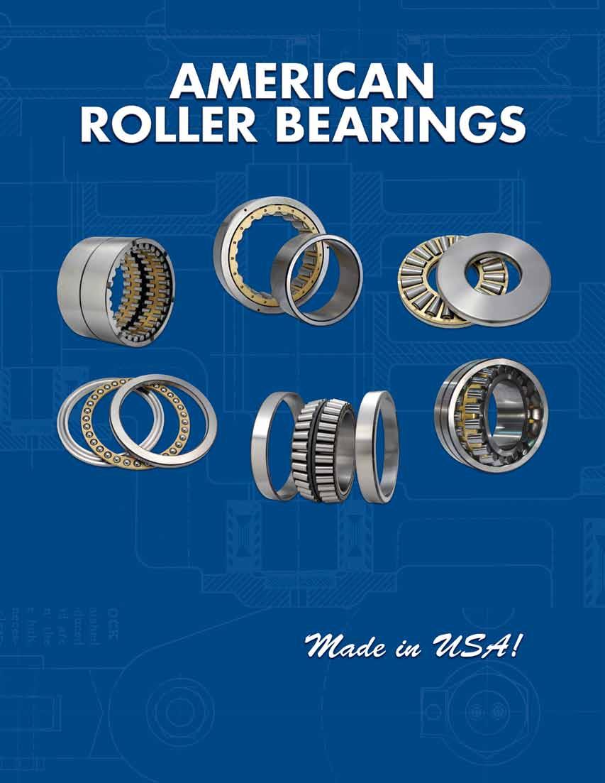
6 INTRODUCTION The American Roller Bearing Company Since 1911, when C.F. Succop helped start American Roller Bearing in Pittsburgh, Pennsylvania, the company has been designing and manufacturing quality anti-friction bearings for thousands of different types of industrial equipment. American Roller Bearings helped U.S. troops win two world wars, powered the greatest industrial expansion in history, and helped America conquer space. Through depression, war, recession and boom, American Roller Bearing has demonstrated success in key sectors of the nation s industrial economy: steel and primary metal manufacturing, railroads, oil and gas, mining, electric power generation, corrugated box manufacturing, aerospace, rock crushing, construction equipment, stamping presses, and large gear box drives. American Roller Bearing has become synonymous with quality. As these industries modernized with newer equipment, so did the bearings we manufactured for this equipment. We ve improved our bearing designs, used higher performance bearing steels, employed newer, more accurate machine tools, and incorporated the latest quality assurance techniques to provide our customers with the finest, longest lasting bearings available. In 1945, William G. Succop took over the management of American Roller Bearing Company and bought out all the remaining investors. In 1966 he orchestrated a major facilities move from Melwood Avenue to a newly constructed factory and headquarters, located at 150 Gamma Drive, Pittsburgh, Pennsylvania. In the 1980 s, the company moved its manufacturing and production to North Carolina, while headquarters remained in Pittsburgh. Today, the third generation owns and manages the American Roller Bearing Company. American s headquarters and primary sales office moved to Hickory, North Carolina in Manufacturing facilities are located close by in Morganton and Hiddenite, North Carolina. Additional sales offices are located in Pittsburgh, Pennsylvania, with regional sales offices throughout the U.S. At the modern manufacturing facilities in the foothills of the North Carolina mountains, American Roller Bearing and its people pay attention to a tradition of craftsmanship that emphasizes quality, workmanship and flexibility traits that have characterized our company since C.F. Succop and Chief Engineer Carl Knaak started designing and manufacturing roller bearings in the early years of the 20th century in Pittsburgh, Pennsylvania. American Roller Bearings proven ability to adapt to industrial change has been on display in the 21st century. We are now designing and expanding a line of heavy duty roller bearings for the next generation of wind turbines that will provide America with a growing share of its electricity from this source. When other industries of the future demand better anti-friction bearings, American Roller Bearing will be there. American Roller Bearing Commitment American Roller Bearing Company has been manufacturing ball and roller bearings for heavy-duty industrial equipment for over one hundred years. Our goal has always been to manufacture a superior product. Implementation of advancements in manufacturing technologies, quality control and continuous improvement programs, assure our future product will continue to excel for the most discerning customers. American Roller Bearing has driven company growth by simultaneously developing customer relationships and products. We ve continuously improved product quality through our focus on engineering and manufacturing technologies, while maintaining a commitment to our customers and the markets we serve. Through a century of change, American Roller Bearing has provided quality roller bearings to a diverse industrial customer base. We continue to develop, design, manufacture, and service the robust bearings that are the keystones of America s industrial economy. American Roller Bearing has made a major contribution to the development of heavy industry and is committed to the continuation of this 100- year tradition of excellence well into the future. The people of American Roller Bearing pledge to do it better every day, designing, developing, manufacturing and servicing better bearings for a 21st century marketplace. American Roller Bearing is proud to remain an American company. This pride is reflected in the high quality and success of our product line, bearings that are increasingly called for by customers around the world. About Our Products American Roller Bearing Company primarily makes heavy duty industrial class bearings that are used in various industries in the US and around the world. With manufacturing capabilities up to 84 outer diameter, American can manufacture a broad range of products to meet your needs. As shown in our product line, American manufactures ball bearings, cylindrical, spherical, and tapered roller bearings in both radial and thrust configurations. Quality Statement American Roller Bearing is a leading manufacturer of quality anti-friction bearings for the industrial markets we serve. Our quality commitment starts with our top management and is supported conscientiously by all the people in our company. We strive to produce exceptional products and services that consistently meet or exceed our customer s requirements and specifications. American Roller Bearing will efficiently apply our resources, and we will involve and train all our people for the purpose of continually improving the quality of our products, processes and services. American Roller Bearing monitors our success by our satisfied customers. We hold and will continue to hold ISO 9001 certifications at all locations. 4
7 INTRODUCTION Warranty American Roller Bearing will replace or repair (at our evaluation), any goods which fail in normal use and service due to defects in material or workmanship free of charge for one year after the date of receipt. Such goods must be returned to American Roller Bearing at its Morganton, North Carolina manufacturing facility, transportation charges prepaid. No return shipments will be accepted without prior written authorization of American Roller Bearing. American Roller Bearing s obligations with respect to such replacement or repair shall not include costs of transportation, installation, adjustment or other expenses which may arise in connection with such replacement or repair. The provisions of this warranty shall not apply to any goods which have not been properly lubricated, subjected to misuse, improper storage conditions, damage due to negligence or accident, or which shall have been repaired or altered in any way so as, in the judgment of American Roller Bearing, to affect adversely their performance and reliability, nor which are used for a purpose for which they are not designed. ROLLER S AGREEMENT TO REPAIR OR REPLACE DEFECTIVE GOODS IS THE EXCLUSIVE REMEDY AND IS EXPRESSLY IN LIEU OF, AND IS HEREBY IN DISCLAIMER OF, ANY IMPLIED WARRANTIES OF MERCHANTABILITY AND/OR FITNESS FOR A PARTICULAR PURPOSE, AS WELL AS ALL OTHER EXPRESS OR IMPLIED WARRANTIES, IN LAW OR EQUITY, AND OF ALL OTHER OBLIGATIONS OR LIABILITIES ON S PART. S EXPRESS WARRANTY HEREUNDER RUNS ONLY TO THE PURCHASER AND PURCHASER S IMMEDIATE BUYER AND DOES NOT EXTEND, EXPRESSLY OR BY IMPLICATION, TO ANY OTHER PERSON. ROLLER S DISCLAIMER OF ALL IMPLIED WARRANTIES RUNS TO ALL SUBSEQUENT PURCHASERS AND USERS, AND PURCHASER WILL PASS THIS DISCLAIMER ON TO ITS BUYER. IN NO EVENT SHALL ROLLER BE LIABLE FOR INCIDENTAL OR CONSEQUENTIAL DAMAGES TO PURCHASER, IMMEDIATE OR REMOTE BUYERS, AND IN NO EVENT MAY THE COMPANY S LIABILITY EXCEED THE PURCHASE PRICE OF THE PRODUCT. Nuclear Application None of the bearings found in this catalog, nor any special bearings not described herein, have been designed or manufactured for use in any nuclear application. This includes any bearings installed or used in devices that could be considered support equipment related in any way to any nuclear application, such as, but not limited to: motors, gear boxes, cranes, carts and valves. The use of our bearings in such applications, without the direct written advance approval and advice of American Roller Bearing s Engineering Department, violates the normal use and service clause of our warranty and shall immediately void all warranties. Engineering Policy For over a century, it has been American Roller Bearing s policy to offer sound engineering assistance to our customers. We have many years experience in the application and manufacture of rolling bearings and are able and willing to help our customers in selecting the best bearing for their application. We also provide proper mounting and lubrication recommendations to insure the bearings will perform at maximum potential for a long time. Using This Catalog The American Roller Bearings shown in this catalog can be found in six sections: Ball Bearings Cylindrical Roller Bearings Tapered Roller Bearings Spherical Roller Bearings Thrust Bearings Special Bearings Many bearings found in the first five product sections are pure standard bearings because they follow a boundary dimension (Bore, O.D. and Width) plan by either the American Bearing Manufacturers Association (ABMA) or the International Standards Organization (ISO). Other bearings are essentially standards because they interchange dimensionally and functionally with those made by several other bearing manufacturers. The Ball Bearings section starts with the two most popular types: deep groove ball bearings and angular contact bearings. These are pure standards, while the other ball bearing product lines in this section interchange with other manufacturers bearings of the same type and boundary dimensions. Cylindrical Roller Bearings, because their various design types are separable, offer the ability to interchange components with bearings from other manufacturers. This only applies to bearing styles with one straight race when the other race contains the cage and rollers. This can easily be verified in the bearing tables by comparing the DUR (Diameter Under Rollers) or F dimension with that of another bearing manufacturer. If they are the same, then interchanging components will be successful. 5
8 INTRODUCTION Similarly, for Tapered Roller Bearings, interchanging a complete bearing can be verified by comparing the boundary dimensions, especially total bearing width, cone width and cup width with those of another manufacturer s bearing. Care must be exercised when selecting some TDO bearings as there exists two and sometimes three with identical boundary dimensions. Each has its own bearing number, and the difference between one another can be seen in the bearing tables in the K factor column. This means different internal geometry and different ability to accommodate axial thrust. Users procuring a replacement bearing should keep this in mind. Most of our tapered roller bearings have the ability to interchange cone assemblies with cups of other manufacturers, and vice versa, but this should be verified by contacting our sales department or engineering department. When components are interchanged for two row bearings, types TDO and TDI, the same Bench End Play (BEP) should be maintained if the original bearing has a spacer. Introduced in this catalog are Spherical Roller Bearings in the popular 22200, 22300, 23000, 23100, 23200, 23800, 23900, 24000, and series. These are all standard bearings with the same boundary dimensions and similar capacities as other bearing brands. Various types of Thrust Bearings are found in this section that use three common types of rolling elements: balls, cylindrical rollers and tapered rollers. All will interchange complete bearing for complete bearing with those made by other manufacturers. There is no standard to allow interchanging of components. The Special Bearings section shows several examples of bearings specially designed to provide unique functions in unique applications. All are shown in general to display our capability to design and manufacture when a special need arises. Additional types can be created when needed. There are no bearing numbers or sizes in this section. Bearing Selection We have constructed this catalog as a general reference guide to American Roller Bearing products and capabilities. The information has been arranged to help the user in the selection of replacement bearings for existing applications and, in general, selection of bearings for new applications. We have attempted to verify the accuracy of the details regarding the bearings found in this catalog. Never the less, it is suggested that purchasers of any of these products seek verification from our engineering department when ordered for the first time. The bearing weights shown for each product are approximate, and if this is an important factor in the use thereof, the purchaser should contact us before placing an order. The three most common reasons for a bearing user to make a selection from a catalog are: 1. To exactly replace a used bearing in a machine. 2. To put new bearings in a new machine. 3. To replace bearing(s) that have not been functioning well in a machine. Most bearings in this catalog are standards and will interchange with those of other bearing manufacturers in existing applications. For new designs or new applications, contact American s sales department at so we can recommend the best bearings for your applications. Selecting a replacement bearing can be very simple, provided the correct and complete bearing number is ordered. Each user of a machine should keep a record available of all the required parts, including the bearing number with its prefixes and suffixes if they exist. Choosing a new bearing for new equipment is a process that usually occurs with OEMs. American Roller Bearing can help in this selection process by doing an analysis to verify that the desired service life will occur and the bearings will allow the machine to operate as intended. Typically, engineers from both companies will be in contact, sharing data on loads, speeds and other operating conditions. When our analysis concludes that we can now specify your bearings, American can supply the proper shaft dimensions, housing dimensions and lubrication recommendations. Often, several iterations of the design and the bearing selection have to be made to optimize equipment performance, and we at American Roller Bearing are committed to helping with this process. Occasionally, bearings must be replaced to improve performance in an application. Our engineering department will perform an in-depth analysis of the machine and its operating conditions. Often, inspections of previously used bearings that have been removed from service are very helpful in identifying the source of a problem. If new bearings are required, the engineers from both companies will work together so the new bearings can be fitted properly into the machine. Dual Dimensioning All the tables in this catalog that list all our bearing products along with their appropriate dimensions, capacities, weights, clearances, etc. are dual dimensioned in SI (Metric) and Imperial (Inch) units for the users convenience. All bearing weights are approximate, and they and capacities have been rounded off from their exact values in both systems. 6
9 INTRODUCTION Industry Standards All of our bearing products conform to ABMA and ISO standards. This insures that all external dimensions and their tolerances are proper so that our bearings will not only physically interchange with those of other manufacturers, but also function and perform as originally intended by the original equipment manufacturer (OEM). All the data concerning our bearing products in this catalog such as dimensions, capacities, tolerances, internal clearance, and fitting recommendations has been carefully reviewed, checked and double checked to insure correctness; however, ROLLER COMPANY ASSUMES NO LIABILITY TO ANY PERSON OR COMPANY FOR ANY DIRECT OR INDIRECT DAMAGES TO PERSON OR PROPERTY BASED ON INFORMATION SHOWN IN THIS CATALOG. Prospective purchasers of our bearing products should contact our sales department at to obtain engineering verification for all pertinent data before ordering. American Roller Bearing Company reserves the right to make changes in design and/or specifications to its products without notice. Bearing Steels Bearing quality steels are the foundation of a successfully manufactured product. Today, either through-hardening or case hardening bearing quality steels are used. The quality of these steels is carefully controlled, and they are manufactured to strict ASTM, (American Society for Testing and Materials) alloy chemistry, mechanical strength and cleanliness specifications. American purchases its bearing steel in the form of bars, tubes and forgings from reliable suppliers. All of these materials are subject to our own incoming quality inspection. Heat Treatment The heat treating processes involved in the hardening of bearing steels are critical and must be executed carefully. The actual process begins with the creation of the alloy in billet form, through the secondary processes as described in the above paragraph, and is completed by our in-house heat treating procedures and QC inspections. All of the care exercised in the execution of proper heat treating results in the finished race or roller, having the most satisfactory physical properties in their relationship to one another and the application itself. Grinding Bearing races and rollers are finished by grinding in modern CNC machines in order to obtain tight tolerances, concentricity, contours, and superior surface finishes. Advanced design and manufacturing provides a long-life bearing that has optimal load sharing among the rolling elements inside each bearing. Races These are the two major components of every typical rolling element bearing. The inner race provides the connection to the rotating part of a machine by being mounted on a shaft, while the outer race connects to the stationary part of a machine by being mounted in a housing. In a small percentage of machines this order is reversed when the equipment has a stationary or dead shaft. Between the races are the rolling elements, either balls or rollers, which share and transmit the load from one race to the other. Several choices of different bearing quality alloy steels are available for the races, and it takes expertise and experience to select the best alloy for each application and load level. Blended Bevel This bearing race feature only applies to cylindrical roller bearings that previously had a simple shallow angle chamfer between the rollerpath and an end face. It is custom designed for each product to facilitate assembly in its application when inner and outer races are mounted separately. The larger and heavier the machine components, the more beneficial this feature becomes. Patented in 1999, the Blended Bevel is a complicated shape with multiple radii that has been designed to allow the bearing s rollers to slide onto the rollerpath surface without scratching or gouging during machine assembly. Originally designed for 4-row cylindricals used as rollneck bearings in bar mills, it is also supplied in many of our standard cylindricals with either a single row, two rows, or four rows of rollers. Rollers All rollers manufactured for American bearings are made from bearing steel, either through-hardened or case hardened, depending on what is best for the bearing and/or its application. All cylindrical, tapered and spherical rollers are then precisely O.D. and end ground to their required sizes and contours. Producing optimally contoured rollers requires a very involved engineering analysis to design a complex shape that is defined by a Logarithmic function. Figure I below is an approximate depiction of a cylindrical roller with a logarithmic contour, with the vertical scale exaggerated. tapered rollers have a similar shape applied to their angled O.D.s, while spherical rollers have a constant full radius. Fig. 1 7


10 INTRODUCTION CAGES Two-Piece Brass Cage-M The cage in all types of rolling element bearings performs the primary function of keeping the rolling elements separated, thereby reducing friction. In roller bearings, they also help reduce roller skew by keeping their axis parallel. A secondary function is keeping all rollers in an assembly in which one or both races are separable. American employs two types of cages in most of its bearings: fully machined brass and pin-type, which is almost exclusively used in tapered roller bearings. These are high quality, high performance cages. In general, different quality cages may be used, but should only be considered after the application has been evaluated. Several types of standard cages used in American bearings are shown on this and the next page. Deep Groove Ball Bearing Cage-M For cylindrical rollers, lid is attached to cage body at assembly. Roller riding is standard, but land riding can be supplied when required. One-Piece Brass Cage-M2 A two-piece solid brass cage with ball pockets, riveted together at bearing assembly. Angular Contact Cage-M A land riding cage with individually formed roller pockets. Typically used for special applications, for both cylindrical and tapered roller bearings. Stamped Steel Cage-SS A one-piece brass land riding cage for ball angular contact bearings. Made from thin mild steel strip, this type of cage can be supplied for cylindrical and tapered roller bearings. 8


11 INTRODUCTION Two-Piece Steel Cage-SM End Ring Cage-ER Same construction as two-piece brass cage except material is mild steel. Finger Type Brass Cage-M Two mild steel rings with short roller pockets. Standard cage for journal bearings. Two-Piece Thrust Cage One piece, with staggered roller pockets on opposite sides. For 2-row and 4-row cylindrical roller bearings and spherical roller bearings. Pin Type Cage Outer band retains rollers at assembly. Used for bearings with cylindrical and tapered rollers. One-Piece Thrust Cage Hardened pins connect two side rings at assembly. Standard cage for tapered roller bearings, optional on some 4-row cylindrical roller bearings. Used for cylindrical roller thrust bearings, tapered roller thrust bearings and v-flat thrust bearings. 9
12 BALL S
13 BALL S Deep Groove Ball Bearings, Metric 14 Deep Groove Ball Bearings, Inch 18 Angular Contact, Metric 20 Special Ball and Angular Contact 24 Special Double Row Angular Contact 28 BALL S Deep Groove Ball Bearings, Metric and Inch Series These bearings are suitable for moderate radial or thrust loads and combined radial/thrust loads. The metric DGB series follow ISO design practices for boundary dimensions, Bore, O.D., Width and corner radii. Both metric and inch series bearings are supplied with a two-piece machined brass cage, ball centered in most sizes, land centered in the very large bearings. Unless otherwise specified by the end user, these bearings will automatically be supplied with a C3 clearance for metric bearings and B3 for inch series ball bearings. This is necessary to provide some mounted clearance since these bearings are typically mounted on a shaft with an interference fit. Please refer to our engineering section for tolerances, internal clearances, and recommended shaft and housing fits for these bearings. The complete metric bearing numbers will have the M cage and C_ clearance suffixes added to the bearing number as follows: DGB61960MC3 This is a 300mm bore bearing. Complete inch bearing numbers will simply have the B clearance suffix added while still providing a machined brass cage as follows: 130DGB553B3 This is a in. bore bearing. Angular Contact (Ball) Bearings, Metric These bearings have a greater number of balls and higher capacities than deep groove ball bearings with the same boundary dimensions and are suitable for higher loads and speeds with proper lubrication. However, because of the absence of a flange on one side of the outer race, they are capable of supporting thrust loading in only one direction. This is why most applications employ two of the same bearing bearings facing opposite directions, often as a duplex pair. Typical duplex pair configurations are shown below. BACK TO BACK FACE TO FACE TANDEM 11
14 BALL S Angular Contact (Ball) Bearings, Metric (Continued) BALL S To obtain American BAC bearings capable of duplex mounting, they must be ordered flush ground, designated by the G suffix. G basically means No axial clearance, no preload. In cases where the tandem mounting is required, another bearing with thrust capability is usually employed on the shaft to take thrust or locate the shaft in the opposite direction as the pair. Preloading is often employed with duplex pairs of BAC bearings for various reasons, and their suffix designations are as follows: flush ground BAC bearings are sold and packaged individually, meaning any two randomly selected G bearings can be mounted together. Preloaded bearings follow the common industry practice of being sold individually, but packaged in pairs. All American angular contact bearings come with a standard machined brass cage and will have an M suffix in their bearing numbers. Angular contact bearings are supplied with four standard contact angles with suffixes as shown below: Unless otherwise specified by the end user, we will supply bearings with the popular 40 degree contact angle: B suffix. The complete angular contact bearing number will be in the following format as required: BAC7056MBG This is a 280mm bearing. Special Deep Groove Ball and Angular (Ball) Contact Bearings These bearings have been specially designed for rolling mills that produce various metal products in various forms such as strip, bars and shapes. Their primary function is to either locate the bearing housing (chock) on the rollneck or take thrust load generated in the rolling process. Their boundary dimensions do not always follow an industry published boundary plan; hence, they are Specials. Their boundary dimensions are often dictated by the primary bearing on a rollneck that accommodates the very large separating force when metals are rolled. Typically, a single DGB bearing is mounted on a rollneck and in a chock that is axially floated in the mill stand. This bearing keeps the stationary chock in axial alignment with the rollneck; hence it is termed an alignment bearing. The opposite chock would then be the held chock that positions the roll axially in the mill stand and accommodates the generated thrust load. Usually, either a duplex pair of angular contact bearings or a double row angular contact bearing is used in the held chock. Typical bearing numbers are: BAC41721 DGB Since these are special bearing numbers, the brass cage, internal clearance, contact angle, etc. are not shown as suffixes in the actual bearing number, making the typical numbers like those shown above complete.
15 BALL S Double Row Angular Contact Bearings These bearings are supplied in two designs in order to maintain a non-separable unit. Design 1 has a single double-row inner race, while design 2 has a single double-row outer race. Due to their construction, they are supplied with a very small positive axial clearance. A typical bearing number is: BALL S BAC5724D DESIGN 1 DESIGN 2 Since this typical bearing has a special bearing number, no suffixes defining the cage type, contact angle or axial clearance are shown in the bearing number, making the bearing number complete as shown. Commonly used DGB and BAC suffixes: Deep Groove Ball: B3, B4 ETC. INTERNAL CLEARANCE, INCH SERIES C3, C4 ETC. INTERNAL CLEARANCE, METRIC SERIES D TWO ROW M MACHINED BRASS CAGE N ONE 45 DEGREE OUTER RACE FACE NOTCH N2 TWO 45 DEGREE OUTER RACE FACE NOTCHES Angular Contact: A B C AC D G GA GB GC G02 G05 G100 G200 G500 M 30 DEGREE CONTACT ANGLE 40 DEGREE CONTACT ANGLE 15 DEGREE CONTACT ANGLE 25 DEGREE CONTACT ANGLE TWO ROW FLUSH GROUND RACES LIGHT PRELOAD, ISO SPECS MEDIUM PRELOAD, ISO SPECS HEAVY PRELOAD, ISO SPECS 20 LBS./90 N PRELOAD, USA SPECS 50 LBS./222 N PRELOAD, USA SPECS 100 LBS./445 N PRELOAD, US SPECS 200 LBS./890 N PRELOAD, USA SPECS 500 LBS./2224 N PRELOAD, USA SPECS MACHINED BRASS CAGE, LAND RIDING 13
16 DEEP GROOVE BALL S, METRIC BALL S w R R D T B S TYPE DGB DGB61940 DGB6040 DGB6240 DGB6340 DGB61944 DGB6044 DGB6244 DGB6344 DGB61948 DGB6048 DGB6248 DGB6348 DGB61952 DGB6052 DGB6252 DGB6352 DGB61956 DGB6056 BORE O.D. WIDTH MAX. FILLET SHOULDER DIAMETERS DYNAMIC STATIC RADIUS SHAFT HSNG. CAPACITY CAPACITY WEIGHT B D W R S T C Co M mm/in mm/in mm/in mm/in mm/in mm/in kn/lbs kn/lbs kg/lbs ,000 32, ,000 50, ,000 64, , , ,000 34, ,000 58, ,000 75, , , ,000 37, ,000 63, , , , , ,000 52, ,000 75, , , , , ,000 55, ,000 81,
17 DEEP GROOVE BALL S, METRIC BALL S DGB6256 DGB6356 DGB61860 DGB61960 DGB6060 DGB6260 DGB6360 DGB61864 DGB61964 DGB6064 DGB6264 DGB6364 DGB61868 DGB61968 DGB6068 DGB61872 DGB61972 DGB6072 DGB61876 DGB61976 DGB6076 DGB61880 DGB61980 DGB6080 DGB61884 BORE O.D. WIDTH MAX. FILLET SHOULDER DIAMETERS DYNAMIC STATIC RADIUS SHAFT HSNG. CAPACITY CAPACITY WEIGHT B D W R S T C Co M mm/in mm/in mm/in mm/in mm/in mm/in kn/lbs kn/lbs kg/lbs , , , , ,500 44, ,000 72, , , , , , , ,500 46, ,000 75, , , , , , , ,000 51, ,000 80, , , ,500 52, ,000 85, , , ,500 72, , , , , ,500 75, , , , , ,500 76,
18 DEEP GROOVE BALL S, METRIC BALL S w R R D T B S TYPE DGB DGB61984 DGB6084 DGB61888 DGB61988 DGB6088 DGB61892 DGB61992 DGB6092 DGB61896 DGB61996 DGB6096 DGB618/500 DGB619/500 DGB60/500 DGB618/530 DGB619/530 DGB60/530 DGB618/560 BORE O.D. WIDTH MAX. FILLET SHOULDER DIAMETERS DYNAMIC STATIC RADIUS SHAFT HSNG. CAPACITY CAPACITY WEIGHT B D W R S T C Co M mm/in mm/in mm/in mm/in mm/in mm/in kn/lbs kn/lbs kg/lbs , , , , ,000 81, , , , , , , , , , , , , , , , , , , , , , , , , , , , , , ,
19 DEEP GROOVE BALL S, METRIC BALL S DGB618/560 DGB619/560 DGB60/560 DGB618/600 DGB619/600 DGB60/600 DGB618/630 DGB619/630 DGB60/630 DGB618/670 DGB619/670 DGB60/670 DGB618/710 DGB619/710 DGB60/710 DGB618/750 DGB619/750 DGB60/750 DGB618/800 DGB619/800 DGB60/800 DGB618/850 DGB618/900 DGB618/950 DGB618/1000 BORE O.D. WIDTH MAX. FILLET SHOULDER DIAMETERS DYNAMIC STATIC RADIUS SHAFT HSNG. CAPACITY CAPACITY WEIGHT B D W R S T C Co M mm/in mm/in mm/in mm/in mm/in mm/in kn/lbs kn/lbs kg/lbs , , , , , , , , , , , , , , , , , , , , , , , , , , , , , , , , , , , , , , , , , , , , , , , , , ,
20 DEEP GROOVE BALL S, INCH BALL S w R R D T B S TYPE DGB 80DGB360 80DGB362 85DGB392 90DGB402 95DGB DGB DGB DGB DGB DGB DGB DGB DGB DGB DGB DGB DGB DGB581 BORE O.D. WIDTH MAX. FILLET SHOULDER DIAMETERS DYNAMIC STATIC RADIUS SHAFT HSNG. CAPACITY CAPACITY WEIGHT B D W R S T C Co M IN/mm IN/mm IN/mm IN/mm IN/mm IN/mm LBS/kN LBS/kN LBS/kg , , , , , , , , , , , , , , , , , , , , , , , , , , , , , , , , , , , ,
21 DEEP GROOVE BALL S, INCH BALL S 140DGB DGB DGB DGB DGB DGB DGB DGB DGB DGB DGB DGB DGB DGB DGB DGB DGB DGB DGB DGB DGB DGB DGB504 BORE O.D. WIDTH MAX. FILLET SHOULDER DIAMETERS DYNAMIC STATIC RADIUS SHAFT HSNG. CAPACITY CAPACITY WEIGHT B D W R S T C Co M IN/mm IN/mm IN/mm IN/mm IN/mm IN/mm LBS/kN LBS/kN LBS/kg , , , , , , , , , , , , , , , , , , , , , , , , , , , , , , , , , , , , , , , , , , , , , , , , , , , , , , , , , , , , , , , , ,
22 ANGULAR CONTACT S, METRIC BALL S R w R D T B S TYPE BAC BAC71940 BAC7040 BAC7240 BAC7340 BAC71944 BAC7044 BAC7244 BAC7344 BAC71948 BAC7048 BAC7248 BAC7348 BAC71852 BAC71952 BAC7252 BAC71856 BAC71956 BAC7056 MAX. FILLET SHOULDER DIAMETERS DYNAMIC STATIC BORE O.D. WIDTH RADIUS SHAFT HSNG. CAPACITY CAPACITY WEIGHT B D W Ri Ro S T C Co M mm/in mm/in mm/in mm/in mm/in mm/in mm/in kn/lbs kn/lbs kg/lbs ,400 44, ,200 71, ,900 95, , , ,000 50, ,600 77, , , , , ,500 60, ,500 84, , , , , ,800 42, ,500 77, , , ,100 54, ,400 85, , ,
23 ANGULAR CONTACT S, METRIC BALL S BAC7256 BAC7356 BAC71860 BAC71960 BAC7060 BAC7260 BAC7360 BAC71864 BAC71964 BAC7064 BAC7264 BAC7364 BAC71868 BAC71968 BAC7068 BAC71872 BAC71972 BAC7072 BAC71876 BAC71976 BAC7076 BAC71880 BAC71980 BAC7080 MAX. FILLET SHOULDER DIAMETERS DYNAMIC STATIC BORE O.D. WIDTH RADIUS SHAFT HSNG. CAPACITY CAPACITY WEIGHT B D W Ri Ro S T C Co M mm/in mm/in mm/in mm/in mm/in mm/in mm/in kn/lbs kn/lbs kg/lbs , , , , ,500 65, , , , , , , , , ,800 68, , , , , , , , , ,600 87, , , , , ,700 95, , , , , , , , , , , , , , , , ,
24 ANGULAR CONTACT S, METRIC BALL S R w R D T B S TYPE BAC BAC71884 BAC71984 BAC7084 BAC71888 BAC71988 BAC7088 BAC71892 BAC71992 BAC7092 BAC71896 BAC71996 BAC7096 BAC718/500 BAC719/500 BAC70/500 BAC718/530 BAC719/530 BAC70/530 MAX. FILLET SHOULDER DIAMETERS DYNAMIC STATIC BORE O.D. WIDTH RADIUS SHAFT HSNG. CAPACITY CAPACITY WEIGHT B D W Ri Ro S T C Co M mm/in mm/in mm/in mm/in mm/in mm/in mm/in kn/lbs kn/lbs kg/lbs , , , , , , , , , , , , , , , , , , , , , , , , , , , , , , , , , , , ,
25 ANGULAR CONTACT S, METRIC BALL S BAC718/560 BAC719/560 BAC70/560 BAC718/600 BAC719/600 BAC70/600 BAC718/630 BAC719/630 BAC70/630 BAC718/670 BAC719/670 BAC70/670 BAC718/710 BAC719/710 BAC70/710 BAC718/750 BAC719/750 BAC70/750 BAC718/800 BAC719/800 BAC70/800 BAC718/850 BAC718/900 BAC718/950 BAC718/1000 MAX. FILLET SHOULDER DIAMETERS DYNAMIC STATIC BORE O.D. WIDTH RADIUS SHAFT HSNG. CAPACITY CAPACITY WEIGHT B D W Ri Ro S T C Co M mm/in mm/in mm/in mm/in mm/in mm/in mm/in kn/lbs kn/lbs kg/lbs , , , , , , , , , , , , , , , , , , , , , , , , , , , , , , , , , , , , , , , , , , , , , , , , , ,
26 SPECIAL DEEP GROOVE BALL & ANGULAR CONTACT BALL S w R R w R R D T B S D T B S TYPE DGB TYPE BAC DGB4797 BAC5753 DGB5747 DGB5748 DGB5749 DGB5761 BAC5817 BAC5824 DGB5834 DGB5963 DGB5915 DGB5922 DGB5931 BAC5964 DBG41038 BORE O.D. BRG. WIDTH MAX. FILLET DYNAMIC STATIC RADIUS CAPACITY CAPACITY WEIGHT B D W/Wo R C Co M mm/in mm/in mm/in mm/in kn/lbs kn/lbs kg/lbs ,300 25, REFERENCE / A / ,300 31, ,500 24, ,200 32, ,600 28, ,100 30, ,900 98, R / A / ,000 50, ,900 33, ,400 32, , , , ,700 50, / A / ,600 56, A ,700 47,
27 SPECIAL DEEP GROOVE BALL & ANGULAR CONTACT BALL S DGB41149 BAC41157 DGB41184 DGB41181 DGB41245 BAC41233 DGB41255 BAC41338 DGB41312 DGB41350 DGB41351 DGB41352 DGB41402 DGB41403 BAC51404 DGB41405 DGB41406 BAC41543 DGB41526 BAC41648 DGB41649 DGB41650 BORE O.D. BRG. WIDTH MAX. FILLET DYNAMIC STATIC RADIUS CAPACITY CAPACITY WEIGHT B D W/Wo R C Co M mm/in mm/in mm/in mm/in kn/lbs kn/lbs kg/lbs REFERENCE ,600 49, A ,200 74, ,900 89, ,500 68, ,500 81, FPB , , BNS ,600 69, A , , ,600 69, ,400 71, , , ,100 79, , , , ,, A , , , , , , , , , , , SC A , , , , , ,
28 SPECIAL DEEP GROOVE BALL & ANGULAR CONTACT BALL S w R R w R R D T B S D T B S TYPE DGB TYPE BAC DGB41651 DGB41652 BAC41721 BAC41814 DGB41819 BAC41939 DGB41907 DGB41932 DGB42011 BAC42033 DGB42023 BAC42025 DGB42027 BAC42228 DGB42210 BORE O.D. BRG. WIDTH MAX. FILLET DYNAMIC STATIC RADIUS CAPACITY CAPACITY WEIGHT B D W/Wo R C Co M mm/in mm/in mm/in mm/in kn/lbs kn/lbs kg/lbs REFERENCE , , , , A , , A , , , , ,900 56, , , E-SC , , , , E-SC ,800 27, , , B , , , , , , , , , E-SC
29 SPECIAL DEEP GROOVE BALL & ANGULAR CONTACT BALL S BAC42320 DGB42519 DGB42508 DGB42521 DGB42619 DGB42708 DGB42714 DGB42707 DGB42823 BAC42910 DGB42903 DGB42906 DGB43107 BAC43109 DGB43111 DGB43317 DGB43306 DGB43701 DGB43903 DGB45902 DGB46201 BORE O.D. BRG. WIDTH MAX. FILLET DYNAMIC STATIC RADIUS CAPACITY CAPACITY WEIGHT B D W/Wo R C Co M mm/in mm/in mm/in mm/in kn/lbs kn/lbs kg/lbs REFERENCE , , , , , , , C , , , , C , , , , , , , , , , , , C , , , , , , , , , , , , , , , , , , A ,000 1,170,
30 SPECIAL DOUBLE ROW ANGULAR CONTACT BALL S R w wi R TYPE BAC-D D T B S DESIGN 1 BAC5522D BAC5521D BAC4513D BAC4683D BAC5616D BAC4676D BAC4684D BAC5620D BAC5764D BAC5766D BAC5724D BAC5768D BAC5725D BAC5722D WIDTH WIDTH MAX. FILLET SHOULDER DIAMETERS DYNAMIC STATIC BORE O.D. O.R. I.R. RADIUS CAPACITY CAPACITY DESIGN BRG. SHAFT HSNG. WT. TYPE B D W Wi R S T C Co M mm/in mm/in mm/in mm/in mm/in mm/in mm/in kn/lbs kn/lbs kg/lbs ,400 45, ,100 47, ,800 63, ,400 35, ,500 55, ,500 55, ,600 67, ,100 76, ,900 48, ,900 48, ,900 65, ,100 76, ,800 49, ,800 68,
31 SPECIAL DOUBLE ROW ANGULAR CONTACT R w BALL S wi R D T B S TYPE BAC-D DESIGN 2 BAC5770D BAC5771D BAC5740D BAC5774D BAC5775D BAC5707D BAC5778D BAC5815D BAC5818D BAC5929D BAC5965D BAC5943D BAC41044D BAC41059D BAC41151D WIDTH WIDTH MAX. FILLET SHOULDER DIAMETERS DYNAMIC STATIC BORE O.D. O.R. I.R. RADIUS CAPACITY CAPACITY DESIGN BRG. SHAFT HSNG. WT. TYPE B D W Wi R S T C Co M mm/in mm/in mm/in mm/in mm/in mm/in mm/in kn/lbs kn/lbs kg/lbs ,400 73, ,300 84, ,900 61, ,500 59, ,900 61, ,200 77, ,900 93, ,000 72, ,000 84, , , , , ,100 93, , , , , , ,
32 CYLINDRICAL
33 CYLINDRICAL ISO Cylindrical 34 Two Row, ISO Cylindrical 78 Full Complement ISO Cylindrical 83 Two Row, ISO Full Comp. Cylindrical 91 Domestic Metric Cylindrical 94 Inch Series Cylindrical 112 Journal Roller - Metric 138 Journal Roller - Type AT 142 Journal Roller - Inch Series 144 Precision End Ring Inch 155 Line Shaft Cylindrical 156 Table Roll Cylindrical 157 Cluster Mill Backing Cylindrical Row Cylindrical Row Cylindrical, Tapered Bore 172 ISO Cylindrical (NU, NJ, etc.) These are metric bearings that are the most common cylindrical roller bearings used around the world, and most manufacturers use the same letter designations for the six most popular styles, making interchanging fairly easy. Bearings with an E suffix, for Extra capacity, are redesigns of the original bearings. The NU type is the most popular design used in heavy duty equipment. Interchangeability can be verified by comparing the boundary dimensions and the value of the F dimension in our bearing tables with those of other manufacturers. Interchangeability can be for both complete bearings and components; i.e. inner races from one manufacturer with outer race assemblies from another. Our standard cage for these bearings is a 2-piece, roller riding brass cage, M designation. Other cage types are: LB 2-piece, land riding brass cage and M2 1-piece, land riding brass cage, for higher speed applications. Bearing internal clearance follows the ISO standard for cylindrical roller bearings, and Normal clearance requires no suffix. However, most applications require a C3 clearance in order to have some mounted clearance after the inner races have been tightly fitted to their shafts. Unless otherwise specified, American will supply these bearings with C3 clearance as a standard. If a clearance other than C3 is needed, including Normal, it should be specified. A typical complete bearing number for standard bearings would be: CYLNDRICAL NU2234EMC3 Two Row, ISO Cylindrical (NNU and NN) These metric designed bearings are wider to allow a second row of rollers for increased capacity. They interchange with complete bearings with the same style designation and basic size number. The cage is a 1-piece brass, roller riding, finger design, M designation. internal clearance values are the same for single row bearings with the same bore size. Unless otherwise specified, bearings will be supplied with a C3 clearance. A typical complete bearing number in this series is: NNU4184MC3 Full Complement ISO Cylindrical (NCF and NJG) These metric designed bearings have the same envelope dimensions as their caged counterparts, and by virtue of more rollers, provide higher capacities. The disadvantage of this design is slightly more internal friction which limits their speed capability. The V suffix indicates full complement. As in the previous product lines, we will supply these bearings with a C3 clearance unless another value is specified. A typical complete bearing numbers in this line is: NCF2338VC3 Two Row, ISO Full Complement Cylindrical (NNCL, NNCF, and NNC) These metric designed two row bearings have the same envelope dimensions as their caged two row counterparts. Having more rollers increases capacities at the expense of lowering their speed limits. Type NNCL is a float or expansion bearing, while type NNCF can be used as a one direction shaft locating bearing and type NNC is a two direction locating bearing. These will be supplied with a C3 clearance unless otherwise specified. A typical complete bearing numbers is: NNCL4964VC3 31
34 CYLINDRICAL Domestic Metric Cylindrical These bearings conform to ABMA Standard 20, Suffix B and are characterized by a larger than normal corner radius on one side of the inner race, a broken corner on the other side, and a standard internal clearance large enough to have a free mounted clearance when a heavy shaft fit is used. American s standard cage for this series of bearings uses a 2 piece fully machined brass type and requires no suffix on the bearing number to identify itself. Alternate cages are a fully machined steel type, SM designation and a stamped steel type, SS designation. The inner race O.D. is controlled so that interchangeability of inner races and outer race assemblies with other manufactures of the same basic bearing number occurs. Typical complete bearing numbers are: CYLNDRICAL CD232, AD5226SS Inch Series Cylindrical These bearings are designed totally in the inch system and interchange as a unit with bearings with the same boundary dimensions from other U.S. manufacturers. A 2 piece fully machined brass cage is standard and does not require suffix identification. Internal clearance is very similar to that of domestic cylindricals with the same bore size, leaving enough free clearance when inner races are tightly fitted. Typical complete bearing numbers are: 90CD789, 155AD791 Journal Roller - Metric These bearings have metric I.D.s and O.D.s, but inch value widths, most of which are sold in the replacement market for older equipment. They are fully separable into their three major components: inner race, outer race and cage/roller assembly. The cage design is the end ring type made from mild steel with shallow pockets for the Roller ends and depends on flat housing surfaces on both sides to retain the cage/roller assembly. Riveted stay rods hold the assembly together. A typical bearing number is: AW234H Journal Roller - Type AT These bearings are intended for use on line shafts. They have special Inch dimensioned bores designed to slip onto standard line shafting and extended and notched inner races so they can be keyed to the line shaft. These bearings should only be used on older line shafts or new applications that are properly designed for them. A typical bearing number is: ATW232H Journal Roller - Inch Series These are 3-piece separable cylindrical roller bearings are of a similar design as the above journal metric series. They were originally designed for various types of heavy industrial equipment. Most of these bearings are sold today in the replacement market. Typical bearing numbers are: SCS166, HCS272, ECS624 Precision End Ring - Inch Series This series of bearings were custom designed for specific applications. Several of these, not shown, have been modified and have a suffix added to the basic bearing number. A typical bearing number is: HCS32 32
35 CYLINDRICAL Line Shaft Cylindrical All of these bearings are based on the 5200 Series found in the previous domestic cylindrical series. The inner races are designed for a slip fit on standard line shafts diameters, and it is extended with a keyway to prevent slipping on the shaft. Extra internal clearance is provided in these bearings, making them unsuitable for typical applications. A typical bearing number is: AD5226SM24 Table Roll Cylindrical Similar to the above series, these bearings are based on the 5200 domestic cylindrical series. Inner race bore sizes are standard metric values, and some are extended to provide additional axial float. Extra internal clearance is provided on most, making them unsuitable for typical applications. A typical bearing number in this series is: CYLNDRICAL AD5238SM16 Cluster Mill Backing Cylindrical These cylindrical roller bearings are provided in several popular sizes for use in cluster mills around the world. They have either two or three rows of rollers and come either with a cage of in a full complement design (F suffix). A typical bearing numbers is: A Row Cylindrical These bearings are designed for and used in rolling mills for various metals and alloys. They come in many design styles as indicated in the bearing tables. The most common cage design is a fully machined finger type made from brass or mild steel. Some bearings are supplied with a steel pin-type cage. Most bearings come standard with a C4 internal clearance as the inner races are usually fitted tightly. Because all have special numbers, there is no cage suffix for brass and C4 clearance. When a steel cage is supplied, the suffix SM is applied. In the larger sizes that roll strip to very tight gauge control, the inner race O.D.s are often supplied semi-finished, RG suffix, so the end user can final grind when mounted on the rollneck. A typical 4 row cylindrical bearing number is: AD41022D 4 Row Cylindrical, Tapered Bore These bearing are very similar to the above series, except the bore of the inner race is tapered: 1 to 12 for smaller bearings and 1 to 30 for larger ones. Internal clearance is special and sufficient to provide proper running clearance as the inner race is expanded when driven up the tapered rollneck. Cage types vary much the same as those above. A typical 4 row cylindrical, tapered bore bearing number is: AD41621DK 33
36 ISO CYLINDRICAL CYLNDRICAL W Ro W Ro W Ro Ri Ri Ri D T2 S1 B F D T1 S2 B E D B E TYPE NU TYPE N TYPE NJ BORE O.D. WIDTH B D W mm/in mm/in mm/in NU315E N315E NJ315E NF315E NUP315E NP315E NU2315 N2315 NJ2315 NF2315 NUP2315 NP2315 NU216E N216E NJ216E NF216E NUP216E NP216E NU2216E N2216E NJ2216E NF2216E NUP2216E NP2216E NU316E N316E NJ316E NF316E NUP316E NP316E NU2316E N2316E NJ2316E NF2316E NUP2316E NP2316E NU217E N217E NJ217E NF217E NUP217E NP217E NU2217E N2217E NJ2217E NF2217E NUP2217E NP2217E NU317E N317E NJ317E NF317E NUP317E NP317E NU2317E N2317E NJ2317E NF2317E NUP2317E NP2317E NU218E N218E NJ218E NF218E NUP218E NP218E NU2218E N2218E NJ2218E NF2218E NUP2218E NP2218E NU318E N318E NJ318E NF318E NUP318E NP318E NU2318E N2318E NJ2318E NF2318E NUP2318E NP2318E NU219E N219E NJ219E NF219E NUP219E NP219E NU2219E N2219E NJ2219E NF2219E NUP2219E NP2219E NU319E N319E NJ319E NF319E NUP319E NP319E NU2319E N2319E NJ2319E NF2319E NUP2319E NP2319E
37 ISO CYLINDRICAL W Ro W Ro W Ro Ri Ri Ri CYLNDRICAL D T2 S2 B E T1 D B F D B E TYPE NF TYPE NUP TYPE NP DIA. UNDER DIA. OVER MAX. FILLET SHOULDER DIAMETERS DYNAMIC STATIC ROLLERS ROLLERS RADIUS SHAFT HOUSING CAPACITY CAPACITY WEIGHT F E Ri Ro S1 S2 T1 T2 C Co M mm/in mm/in mm/in mm/in mm/in mm/in mm/in mm/in kn/lbs kn/lbs kg/lbs ,000 59, ,200 90, ,500 37, ,300 55, ,500 65, ,000 99, ,100 45, ,400 63, ,500 75, , , ,600 49, ,000 70, ,000 81, ,000 99, ,500 59, ,100 84, ,500 87, , , BASIC 315E 2315E 216E 2216E 316E 2316E 217E 2217E 317E 2317E 218E 2218E 318E 2318E 219E 2219E 319E 2319E 35
38 ISO CYLINDRICAL CYLNDRICAL W Ro W Ro W Ro Ri Ri Ri D T2 S1 B F D T1 S2 B E D B E TYPE NU TYPE N TYPE NJ BORE O.D. WIDTH B D W mm/in mm/in mm/in NU1020 N1020 NJ1020 NF1020 NUP1020 NP1020 NU3120 N3120 NJ3120 NF3120 NUP3120 NP3120 NU220E N220E NJ220E NF220E NUP220E NP220E NU2220E N2220E NJ2220E NF2220E NUP2220E NP2220E NU320E N320E NJ320E NF320E NUP320E NP320E NU2320E N2320E NJ2320E NF2320E NUP2320E NP2320E NU1021 N1021 NJ1021 NF1021 NUP1021 NP1021 NU221E N221E NJ221E NF221E NUP221E NP221E NU2221E N2221E NJ2221E NF2221E NUP2221E NP2221E NU321E N321E NJ321E NF321E NUP321E NP321E NU2321E N2321E NJ2321E NF2321E NUP2321E NP2321E NU1022 N1022 NJ1022 NF1022 NUP1022 NP1022 NU3122 N3122 NJ3122 NF3122 NUP3122 NP3122 NU222E N222E NJ222E NF222E NUP222E NP222E NU2222E N2222E NJ2222E NF2222E NUP2222E NP2222E NU322E N322E NJ322E NF322E NUP322E NP322E NU2322E N2322E NJ2322E NF2322E NUP2322E NP2322E
39 ISO CYLINDRICAL W Ro W Ro W Ro Ri Ri Ri CYLNDRICAL D T2 S2 B E T1 D B F D B E TYPE NF TYPE NUP TYPE NP DIA. UNDER DIA. OVER MAX. FILLET SHOULDER DIAMETERS DYNAMIC STATIC ROLLERS ROLLERS RADIUS SHAFT HOUSING CAPACITY CAPACITY WEIGHT F E Ri Ro S1 S2 T1 T2 C Co M mm/in mm/in mm/in mm/in mm/in mm/in mm/in mm/in kn/lbs kn/lbs kg/lbs ,100 25, , , ,200 67, , , ,000 99, , , , , ,600 70, , , , , , , ,100 37, , , ,200 82, , , , , , , BASIC E 2220E 320E 2320E E 2221E 321E 2321E E 2222E 322E 2322E 37
40 ISO CYLINDRICAL CYLNDRICAL W Ro W Ro W Ro Ri Ri Ri D T2 S1 B F D T1 S2 B E D B E TYPE NU TYPE N TYPE NJ BORE O.D. WIDTH B D W mm/in mm/in mm/in NU323 N323 NJ323 NF323 NUP323 NP323 NU323E N323E NJ323E NF323E NUP323E NP323E NU1024 N1024 NJ1024 NF1024 NUP1024 NP1024 NU3124 N3124 NJ3124 NF3124 NUP3124 NP3124 NU224E N224E NJ224E NF224E NUP224E NP224E NU2224E N2224E NJ2224E NF2224E NUP2224E NP2224E NU324E N324E NJ324E NF324E NUP324E NP324E NU2324E N2324E NJ2324E NF2324E NUP2324E NP2324E NU1026E N1026E NJ1026E NF1026E NUP1026E NP1026E NU2026E N2026E NJ2026E NF2026E NUP2026E NP2026E NU3026 N3026 NJ3026 NF3026 NUP3026 NP3026 NU226E N226E NJ226E NF226E NUP226E NP226E NU2226E N2226E NJ2226E NF2226E NUP2226E NP2226E NU326E N326E NJ326E NF326E NUP326E NP326E NU2326E N2326E NJ2326E NF2326E NUP2326E NP2326E NU1028 N1028 NJ1028 NF1028 NUP1028 NP1028 NU2028E N2028E NJ2028E NF2028E NUP2028E NP2028E
41 ISO CYLINDRICAL W Ro W Ro W Ro Ri Ri Ri CYLNDRICAL D T2 S2 B E T1 D B F D B E TYPE NF TYPE NUP TYPE NP DIA. UNDER DIA. OVER MAX. FILLET SHOULDER DIAMETERS DYNAMIC STATIC ROLLERS ROLLERS RADIUS SHAFT HOUSING CAPACITY CAPACITY WEIGHT F E Ri Ro S1 S2 T1 T2 C Co M mm/in mm/in mm/in mm/in mm/in mm/in mm/in mm/in kn/lbs kn/lbs kg/lbs , , , , ,100 40, , , ,400 97, , , , , , , , ,100 50, ,400 99, , , , , , , , , , , ,300 55, , , BASIC E E 2224E 324E 2324E 1026E 2026E E 2226E 326E 2326E E 39
42 ISO CYLINDRICAL CYLNDRICAL W Ro W Ro W Ro Ri Ri Ri D T2 S1 B F D T1 S2 B E D B E TYPE NU TYPE N TYPE NJ BORE O.D. WIDTH B D W mm/in mm/in mm/in NU3028 N3028 NJ3028 NF3028 NUP3028 NP3028 NU3128 N3128 NJ3128 NF3128 NUP3128 NP3128 NU228E N228E NJ228E NF228E NUP228E NP228E NU2228E N2228E NJ2228E NF2228E NUP2228E NP2228E NU328E N328E NJ328E NF328E NUP328E NP328E NU2328E N2328E NJ2328E NF2328E NUP2328E NP2328E NU1030 N1030 NJ1030 NF1030 NUP1030 NP1030 NU2030 N2030 NJ2030 NF2030 NUP2030 NP2030 NU3030 N3030 NJ3030 NF3030 NUP3030 NP3030 NU230E N230E NJ230E NF230E NUP230E NP230E NU2230E N2230E NJ2230E NF2230E NUP2230E NP2230E NU330E N330E NJ330E NF330E NUP330E NP330E NU2330E N2330E NJ2330E NF2330E NUP2330E NP2330E NU1032 N1032 NJ1032 NF1032 NUP1032 NP1032 NU2032E N2032E NJ2032E NF2032E NUP2032E NP2032E NU3032 N3032 NJ3032 NF3032 NUP3032 NP3032 NU232E N232E NJ232E NF232E NUP232E NP232E NU2232E N2232E NJ2232E NF2232E NUP2232E NP2232E
43 ISO CYLINDRICAL W Ro W Ro W Ro Ri Ri Ri CYLNDRICAL D T2 S2 B E T1 D B F D B E TYPE NF TYPE NUP TYPE NP DIA. UNDER DIA. OVER MAX. FILLET SHOULDER DIAMETERS DYNAMIC STATIC ROLLERS ROLLERS RADIUS SHAFT HOUSING CAPACITY CAPACITY WEIGHT F E Ri Ro S1 S2 T1 T2 C Co M mm/in mm/in mm/in mm/in mm/in mm/in mm/in mm/in kn/lbs kn/lbs kg/lbs , , , , , , , , , , , , ,800 61, , , , , , , , , , , , , ,700 73, , , , , , , , , BASIC E 2228E 328E 2328E E 2230E 330E 2330E E E 2232E 41
44 ISO CYLINDRICAL CYLNDRICAL W Ro W Ro W Ro Ri Ri Ri D T2 S1 B F D T1 S2 B E D B E TYPE NU TYPE N TYPE NJ BORE O.D. WIDTH B D W mm/in mm/in mm/in NU332E N332E NJ332E NF332E NUP332E NP332E NU2332E N2332E NJ2332E NF2332E NUP2332E NP2332E NU2934 N2934 NJ2934 NF2934 NUP2934 NP2934 NU1034 N1034 NJ1034 NF1034 NUP1034 NP1034 NU2034E N2034E NJ2034E NF2034E NUP2034E NP2034E NU3034 N3034 NJ3034 NF3034 NUP3034 NP3034 NU3134 N3134 NJ3134 NF3134 NUP3134 NP3134 NU234E N234E NJ234E NF234E NUP234E NP234E NU2234E N2234E NJ2234E NF2234E NUP2234E NP2234E NU334 N334 NJ334 NF334 NUP334 NP334 NU334E N334E NJ334E NF334E NUP334E NP334E NU2334E N2334E NJ2334E NF2334E NUP2334E NP2334E NU1936E N1936E NJ1936E NF1936E NUP1936E NP1936E NU2936 N2936 NJ2936 NF2936 NUP2936 NP2936 NU1036 N1036 NJ1036 NF1036 NUP1036 NP1036 NU2036E N2036E NJ2036E NF2036E NUP2036E NP2036E NU3036 N3036 NJ3036 NF3036 NUP3036 NP
45 ISO CYLINDRICAL W Ro W Ro W Ro Ri Ri Ri CYLNDRICAL D T2 S2 B E T1 D B F D B E TYPE NF TYPE NUP TYPE NP DIA. UNDER DIA. OVER MAX. FILLET SHOULDER DIAMETERS DYNAMIC STATIC ROLLERS ROLLERS RADIUS SHAFT HOUSING CAPACITY CAPACITY WEIGHT F E Ri Ro S1 S2 T1 T2 C Co M mm/in mm/in mm/in mm/in mm/in mm/in mm/in mm/in kn/lbs kn/lbs kg/lbs , , , , ,200 81, ,800 90, , , , , , , , , , , , , , , , , ,100 87, ,500 99, , , , , , , BASIC 332E 2332E E E 2234E E 2334E 1936E E
46 ISO CYLINDRICAL CYLNDRICAL W Ro W Ro W Ro Ri Ri Ri D T2 S1 B F D T1 S2 B E D B E TYPE NU TYPE N TYPE NJ BORE O.D. WIDTH B D W mm/in mm/in mm/in NU236 N236 NJ236 NF236 NUP236 NP236 NU236E N236E NJ236E NF236E NUP236E NP236E NU2236E N2236E NJ2236E NF2236E NUP2236E NP2236E NU336 N336 NJ336 NF336 NUP336 NP336 NU336E N336E NJ336E NF336E NUP336E NP336E NU2336E N2336E NJ2336E NF2336E NUP2336E NP2336E NU1938E N1938E NJ1938E NF1938E NUP1938E NP1938E NU2938 N2938 NJ2938 NF2938 NUP2938 NP2938 NU1038 N1038 NJ1038 NF1038 NUP1038 NP1038 NU2038E N2038E NJ2038E NF2038E NUP2038E NP2038E NU3038 N3038 NJ3038 NF3038 NUP3038 NP3038 NU238E N238E NJ238E NF238E NUP238E NP238E NU2238E N2238E NJ2238E NF2238E NUP2238E NP2238E NU338E N338E NJ338E NF338E NUP338E NP338E NU2338E N2338E NJ2338E NF2338E NUP2338E NP2338E NU1840 N1840 NJ1840 NF1840 NUP1840 NP1840 NU1940E N1940E NJ1940E NF1940E NUP1940E NP1940E
47 ISO CYLINDRICAL W Ro W Ro W Ro Ri Ri Ri CYLNDRICAL D T2 S2 B E T1 D B F D B E TYPE NF TYPE NUP TYPE NP DIA. UNDER DIA. OVER MAX. FILLET SHOULDER DIAMETERS DYNAMIC STATIC ROLLERS ROLLERS RADIUS SHAFT HOUSING CAPACITY CAPACITY WEIGHT F E Ri Ro S1 S2 T1 T2 C Co M mm/in mm/in mm/in mm/in mm/in mm/in mm/in mm/in kn/lbs kn/lbs kg/lbs , , , , , , , , , , , , ,200 90, , , , , , , , , , , , , , , , , ,200 50, ,600 91, BASIC E 2236E E 2336E 1938E E E 2238E 338E 2338E E 45
48 ISO CYLINDRICAL CYLNDRICAL W Ro W Ro W Ro Ri Ri Ri D T2 S1 B F D T1 S2 B E D B E TYPE NU TYPE N TYPE NJ BORE O.D. WIDTH B D W mm/in mm/in mm/in NU2940 N2940 NJ2940 NF2940 NUP2940 NP2940 NU3940 N3940 NJ3940 NF3940 NUP3940 NP3940 NU1040 N1040 NJ1040 NF1040 NUP1040 NP1040 NU2040E N2040E NJ2040E NF2040E NUP2040E NP2040E NU3040 N3040 NJ3040 NF3040 NUP3040 NP3040 NU3140 N3140 NJ3140 NF3140 NUP3140 NP3140 NU240E N240E NJ240E NF240E NUP240E NP240E NU2240E N2240E NJ2240E NF2240E NUP2240E NP2240E NU340E N340E NJ340E NF340E NUP340E NP340E NU2340E N2340E NJ2340E NF2340E NUP2340E NP2340E NU1844 N1844 NJ1844 NF1844 NUP1844 NP1844 NU1944E N1944E NJ1944E NF1944E NUP1944E NP1944E NU2944E N2944E NJ2944E NF2944E NUP2944E NP2944E NU3944 N3944 NJ3944 NF3944 NUP3944 NP3944 NU1044 N1044 NJ1044 NF1044 NUP1044 NP1044 NU2044E N2044E NJ2044E NF2044E NUP2044E NP2044E NU3044 N3044 NJ3044 NF3044 NUP3044 NP3044 NU3144 N3144 NJ3144 NF3144 NUP3144 NP
49 ISO CYLINDRICAL W Ro W Ro W Ro Ri Ri Ri CYLNDRICAL D T2 S2 B E T1 D B F D B E TYPE NF TYPE NUP TYPE NP DIA. UNDER DIA. OVER MAX. FILLET SHOULDER DIAMETERS DYNAMIC STATIC ROLLERS ROLLERS RADIUS SHAFT HOUSING CAPACITY CAPACITY WEIGHT F E Ri Ro S1 S2 T1 T2 C Co M mm/in mm/in mm/in mm/in mm/in mm/in mm/in mm/in kn/lbs kn/lbs kg/lbs , , , , , , , , , , , , , , , , , , , , ,200 54, , , , , , , , , , , , , , , BASIC E E 2240E 340E 2340E E 2944E E
50 ISO CYLINDRICAL CYLNDRICAL W Ro W Ro W Ro Ri Ri Ri D T2 S1 B F D T1 S2 B E D B E TYPE NU TYPE N TYPE NJ BORE O.D. WIDTH B D W mm/in mm/in mm/in NU244 N244 NJ244 NF244 NUP244 NP244 NU244E N244E NJ244E NF244E NUP244E NP244E NU2244 N2244 NJ2244 NF2244 NUP2244 NP2244 NU2244E N2244E NJ2244E NF2244E NUP2244E NP2244E NU344 N344 NJ344 NF344 NUP344 NP344 NU344E N344E NJ344E NF344E NUP344E NP344E NU2344 N2344 NJ2344 NF2344 NUP2344 NP2344 NU2344E N2344E NJ2344E NF2344E NUP2344E NP2344E NU1848 N1848 NJ1848 NF1848 NUP1848 NP1848 NU1948 N1948 NJ1948 NF1948 NUP1948 NP1948 NU2948 N2948 NJ2948 NF2948 NUP2948 NP2948 NU3948 N3948 NJ3948 NF3948 NUP3948 NP3948 NU1048E N1048E NJ1048E NF1048E NUP1048E NP1048E NU2048E N2048E NJ2048E NF2048E NUP2048E NP2048E NU3048E N3048E NJ3048E NF3048E NUP3048E NP3048E NU3148 N3148 NJ3148 NF3148 NUP3148 NP3148 NU248 N248 NJ248 NF248 NUP248 NP
51 ISO CYLINDRICAL W Ro W Ro W Ro Ri Ri Ri CYLNDRICAL D T2 S2 B E T1 D B F D B E TYPE NF TYPE NUP TYPE NP DIA. UNDER DIA. OVER MAX. FILLET SHOULDER DIAMETERS DYNAMIC STATIC ROLLERS ROLLERS RADIUS SHAFT HOUSING CAPACITY CAPACITY WEIGHT F E Ri Ro S1 S2 T1 T2 C Co M mm/in mm/in mm/in mm/in mm/in mm/in mm/in mm/in kn/lbs kn/lbs kg/lbs , , , , , , , , , , , , , , , , ,800 78, , , , , , , , , , , , , , , , , BASIC E E E E E 2048E 3048E
52 ISO CYLINDRICAL CYLNDRICAL W Ro W Ro W Ro Ri Ri Ri D T2 S1 B F D T1 S2 B E D B E TYPE NU TYPE N TYPE NJ BORE O.D. WIDTH B D W mm/in mm/in mm/in NU2248 N2248 NJ2248 NF2248 NUP2248 NP2248 NU348 N348 NJ348 NF348 NUP348 NP348 NU2348 N2348 NJ2348 NF2348 NUP2348 NP2348 NU1852 N1852 NJ1852 NF1852 NUP1852 NP1852 NU1952E N1952E NJ1952E NF1952E NUP1952E NP1952E NU2952 N2952 NJ2952 NF2952 NUP2952 NP2952 NU3952 N3952 NJ3952 NF3952 NUP3952 NP3952 NU1052 N1052 NJ1052 NF1052 NUP1052 NP1052 NU2052E N2052E NJ2052E NF2052E NUP2052E NP2052E NU3052E N3052E NJ3052E NF3052E NUP3052E NP3052E NU3152E N3152E NJ3152E NF3152E NUP3152E NP3152E NU252 N252 NJ252 NF252 NUP252 NP252 NU252E N252E NJ252E NF252E NUP252E NP252E NU2252 N2252 NJ2252 NF2252 NUP2252 NP2252 NU2252E N2252E NJ2252E NF2252E NUP2252E NP2252E NU352E N352E NJ352E NF352E NUP352E NP352E NU2352E N2352E NJ2352E NF2352E NUP2352E NP2352E NU1856 N1856 NJ1856 NF1856 NUP1856 NP
53 ISO CYLINDRICAL W Ro W Ro W Ro Ri Ri Ri CYLNDRICAL D T2 S2 B E T1 D B F D B E TYPE NF TYPE NUP TYPE NP DIA. UNDER DIA. OVER MAX. FILLET SHOULDER DIAMETERS DYNAMIC STATIC ROLLERS ROLLERS RADIUS SHAFT HOUSING CAPACITY CAPACITY WEIGHT F E Ri Ro S1 S2 T1 T2 C Co M mm/in mm/in mm/in mm/in mm/in mm/in mm/in mm/in kn/lbs kn/lbs kg/lbs , , , , , , ,000 83, , , , , , , , , , , , , , , , , , , , , , , , , ,100 1,012, , , BASIC E E 3052E 3152E E E 352E 2352E
54 ISO CYLINDRICAL CYLNDRICAL W Ro W Ro W Ro Ri Ri Ri D T2 S1 B F D T1 S2 B E D B E TYPE NU TYPE N TYPE NJ BORE O.D. WIDTH B D W mm/in mm/in mm/in NU2856E N2856E NJ2856E NF2856E NUP2856E NP2856E NU1956 N1956 NJ1956 NF1956 NUP1956 NP1956 NU1956E N1956E NJ1956E NF1956E NUP1956E NP1956E NU2956E N2956E NJ2956E NF2956E NUP2956E NP2956E NU3956 N3956 NJ3956 NF3956 NUP3956 NP3956 NU1056 N1056 NJ1056 NF1056 NUP1056 NP1056 NU2056E N2056E NJ2056E NF2056E NUP2056E NP2056E NU3056 N3056 NJ3056 NF3056 NUP3056 NP3056 NU3156E N3156E NJ3156E NF3156E NUP3156E NP3156E NU256 N256 NJ256 NF256 NUP256 NP256 NU256E N256E NJ256E NF256E NUP256E NP256E NU2256E N2256E NJ2256E NF2256E NUP2256E NP2256E NU356E N356E NJ356E NF356E NUP356E NP356E NU2356E N2356E NJ2356E NF2356E NUP2356E NP2356E NU1860E N1860E NJ1860E NF1860E NUP1860E NP1860E NU1960E N1960E NJ1960E NF1960E NUP1960E NP1960E NU2960E N2960E NJ2960E NF2960E NUP2960E NP2960E
55 ISO CYLINDRICAL W Ro W Ro W Ro Ri Ri Ri CYLNDRICAL D T2 S2 B E T1 D B F D B E TYPE NF TYPE NUP TYPE NP DIA. UNDER DIA. OVER MAX. FILLET SHOULDER DIAMETERS DYNAMIC STATIC ROLLERS ROLLERS RADIUS SHAFT HOUSING CAPACITY CAPACITY WEIGHT F E Ri Ro S1 S2 T1 T2 C Co M mm/in mm/in mm/in mm/in mm/in mm/in mm/in mm/in kn/lbs kn/lbs kg/lbs , , , , , , , , , , , , , , , , , , , , , , , , , , ,400 1,160, , , , , , , BASIC 2856E E 2956E E E E 2256E 356E 2356E 1860E 1960E 2960E 53
56 ISO CYLINDRICAL CYLNDRICAL W Ro W Ro W Ro Ri Ri Ri D T2 S1 B F D T1 S2 B E D B E TYPE NU TYPE N TYPE NJ BORE O.D. WIDTH B D W mm/in mm/in mm/in NU3960 N3960 NJ3960 NF3960 NUP3960 NP3960 NU1060 N1060 NJ1060 NF1060 NUP1060 NP1060 NU2060E N2060E NJ2060E NF2060E NUP2060E NP2060E NU3060 N3060 NJ3060 NF3060 NUP3060 NP3060 NU260E N260E NJ260E NF260E NUP260E NP260E NU2260 N2260 NJ2260 NF2260 NUP2260 NP2260 NU360 N360 NJ360 NF360 NUP360 NP360 NU2360E N2360E NJ2360E NF2360E NUP2360E NP2360E NU1864 N1864 NJ1864 NF1864 NUP1864 NP1864 NU1964 N1964 NJ1964 NF1964 NUP1964 NP1964 NU2964 N2964 NJ2964 NF2964 NUP2964 NP2964 NU3964 N3964 NJ3964 NF3964 NUP3964 NP3964 NU1064 N1064 NJ1064 NF1064 NUP1064 NP1064 NU2064E N2064E NJ2064E NF2064E NUP2064E NP2064E NU3064E N3064E NJ3064E NF3064E NUP3064E NP3064E NU3164E N3164E NJ3164E NF3164E NUP3164E NP3164E NU264E N264E NJ264E NF264E NUP264E NP264E NU2264 N2264 NJ2264 NF2264 NUP2264 NP
57 ISO CYLINDRICAL W Ro W Ro W Ro Ri Ri Ri CYLNDRICAL D T2 S2 B E T1 D B F D B E TYPE NF TYPE NUP TYPE NP DIA. UNDER DIA. OVER MAX. FILLET SHOULDER DIAMETERS DYNAMIC STATIC ROLLERS ROLLERS RADIUS SHAFT HOUSING CAPACITY CAPACITY WEIGHT F E Ri Ro S1 S2 T1 T2 C Co M mm/in mm/in mm/in mm/in mm/in mm/in mm/in mm/in kn/lbs kn/lbs kg/lbs , , , , , , , , , , , , , , ,700 1,315, , , , , , , , , , , , , , , ,900 1,214, , , , , BASIC E E E E 3064E 3164E 264E
58 ISO CYLINDRICAL CYLNDRICAL W Ro W Ro W Ro Ri Ri Ri D T2 S1 B F D T1 S2 B E D B E TYPE NU TYPE N TYPE NJ BORE O.D. WIDTH B D W mm/in mm/in mm/in NU2264E N2264E NJ2264E NF2264E NUP2264E NP2264E NU364 N364 NJ364 NF364 NUP364 NP364 NU2364 N2364 NJ2364 NF2364 NUP2364 NP2364 NU1868 N1868 NJ1868 NF1868 NUP1868 NP1868 NU1968E N1968E NJ1968E NF1968E NUP1968E NP1968E NU2968E N2968E NJ2968E NF2968E NUP2968E NP2968E NU3968 N3968 NJ3968 NF3968 NUP3968 NP3968 NU1068 N1068 NJ1068 NF1068 NUP1068 NP1068 NU2068E N2068E NJ2068E NF2068E NUP2068E NP2068E NU3068 N3068 NJ3068 NF3068 NUP3068 NP3068 NU3168E N3168E NJ3168E NF3168E NUP3168E NP3168E NU268 N268 NJ268 NF268 NUP268 NP268 NU2268 N2268 NJ2268 NF2268 NUP2268 NP2268 NU368 N368 NJ368 NF368 NUP368 NP368 NU2368 N2368 NJ2368 NF2368 NUP2368 NP2368 NU1872 N1872 NJ1872 NF1872 NUP1872 NP1872 NU1972 N1972 NJ1972 NF1972 NUP1972 NP
59 ISO CYLINDRICAL W Ro W Ro W Ro Ri Ri Ri CYLNDRICAL D T2 S2 B E T1 D B F D B E TYPE NF TYPE NUP TYPE NP DIA. UNDER DIA. OVER MAX. FILLET SHOULDER DIAMETERS DYNAMIC STATIC ROLLERS ROLLERS RADIUS SHAFT HOUSING CAPACITY CAPACITY WEIGHT F E Ri Ro S1 S2 T1 T2 C Co M mm/in mm/in mm/in mm/in mm/in mm/in mm/in mm/in kn/lbs kn/lbs kg/lbs ,400 1,100, , , ,900 1,589, , , , , , , , , , , , , , , ,100 1,281, , , ,500 1,012, , , ,023,000 1,845, , , , , BASIC 2264E E 2968E E E
60 ISO CYLINDRICAL CYLNDRICAL W Ro W Ro W Ro Ri Ri Ri D T2 S1 B F D T1 S2 B E D B E TYPE NU TYPE N TYPE NJ BORE O.D. WIDTH B D W mm/in mm/in mm/in NU3972 N3972 NJ3972 NF3972 NUP3972 NP3972 NU1072 N1072 NJ1072 NF1072 NUP1072 NP1072 NU2072E N2072E NJ2072E NF2072E NUP2072E NP2072E NU3072 N3072 NJ3072 NF3072 NUP3072 NP3072 NU3172E N3172E NJ3172E NF3172E NUP3172E NP3172E NU272 N272 NJ272 NF272 NUP272 NP272 NU2272 N2272 NJ2272 NF2272 NUP2272 NP2272 NU372 N372 NJ372 NF372 NUP372 NP372 NU2372 N2372 NJ2372 NF2372 NUP2372 NP2372 NU1876E N1876E NJ1876E NF1876E NUP1876E NP1876E NU1976 N1976 NJ1976 NF1976 NUP1976 NP1976 NU3976 N3976 NJ3976 NF3976 NUP3976 NP3976 NU1076 N1076 NJ1076 NF1076 NUP1076 NP1076 NU2076E N2076E NJ2076E NF2076E NUP2076E NP2076E NU3076E N3076E NJ3076E NF3076E NUP3076E NP3076E NU3176 N3176 NJ3176 NF3176 NUP3176 NP3176 NU276 N276 NJ276 NF276 NUP276 NP276 NU2276 N2276 NJ2276 NF2276 NUP2276 NP
61 ISO CYLINDRICAL W Ro W Ro W Ro Ri Ri Ri CYLNDRICAL D T2 S2 B E T1 D B F D B E TYPE NF TYPE NUP TYPE NP DIA. UNDER DIA. OVER MAX. FILLET SHOULDER DIAMETERS DYNAMIC STATIC ROLLERS ROLLERS RADIUS SHAFT HOUSING CAPACITY CAPACITY WEIGHT F E Ri Ro S1 S2 T1 T2 C Co M mm/in mm/in mm/in mm/in mm/in mm/in mm/in mm/in kn/lbs kn/lbs kg/lbs , , , , , , , , ,660 1,281, , , ,700 1,360, , , ,170,000 1,866, , , , , , , , , , , ,000 1,068, ,700 1,789, , , ,600 1,488, BASIC E E E E 3076E
62 ISO CYLINDRICAL CYLNDRICAL W Ro W Ro W Ro Ri Ri Ri D T2 S1 B F D T1 S2 B E D B E TYPE NU TYPE N TYPE NJ BORE O.D. WIDTH B D W mm/in mm/in mm/in NU376 N376 NJ376 NF376 NUP376 NP376 NU2376 N2376 NJ2376 NF2376 NUP2376 NP2376 NU1880 N1880 NJ1880 NF1880 NUP1880 NP1880 NU1980E N1980E NJ1980E NF1980E NUP1980E NP1980E NU2980E N2980E NJ2980E NF2980E NUP2980E NP2980E NU3980 N3980 NJ3980 NF3980 NUP3980 NP3980 NU1080 N1080 NJ1080 NF1080 NUP1080 NP1080 NU2080E N2080E NJ2080E NF2080E NUP2080E NP2080E NU3080 N3080 NJ3080 NF3080 NUP3080 NP3080 NU3180 N3180 NJ3180 NF3180 NUP3180 NP3180 NU280 N280 NJ280 NF280 NUP280 NP280 NU2280 N2280 NJ2280 NF2280 NUP2280 NP2280 NU1884 N1884 NJ1884 NF1884 NUP1884 NP1884 NU1984E N1984E NJ1984E NF1984E NUP1984E NP1984E NU2984 N2984 NJ2984 NF2984 NUP2984 NP2984 NU3984 N3984 NJ3984 NF3984 NUP3984 NP3984 NU1084 N1084 NJ1084 NF1084 NUP1084 NP
63 ISO CYLINDRICAL W Ro W Ro W Ro Ri Ri Ri CYLNDRICAL D T2 S2 B E T1 D B F D B E TYPE NF TYPE NUP TYPE NP DIA. UNDER DIA. OVER MAX. FILLET SHOULDER DIAMETERS DYNAMIC STATIC ROLLERS ROLLERS RADIUS SHAFT HOUSING CAPACITY CAPACITY WEIGHT F E Ri Ro S1 S2 T1 T2 C Co M mm/in mm/in mm/in mm/in mm/in mm/in mm/in mm/in kn/lbs kn/lbs kg/lbs ,000 1,120, ,495,000 2,809, , , , , , , , , , , ,000 1,068, ,700 1,236, ,500 1,893, , , ,700 1,739, , , , , , , , , , , BASIC E 2980E E E
64 ISO CYLINDRICAL CYLNDRICAL W Ro W Ro W Ro Ri Ri Ri D T2 S1 B F D T1 S2 B E D B E TYPE NU TYPE N TYPE NJ BORE O.D. WIDTH B D W mm/in mm/in mm/in NU2084E N2084E NJ2084E NF2084E NUP2084E NP2084E NU3084 N3084 NJ3084 NF3084 NUP3084 NP3084 NU3184E N3184E NJ3184E NF3184E NUP3184E NP3184E NU284 N284 NJ284 NF284 NUP284 NP284 NU2284 N2284 NJ2284 NF2284 NUP2284 NP2284 NU1888 N1888 NJ1888 NF1888 NUP1888 NP1888 NU1988 N1988 NJ1988 NF1988 NUP1988 NP1988 NU2988E N2988E NJ2988E NF2988E NUP2988E NP2988E NU3988 N3988 NJ3988 NF3988 NUP3988 NP3988 NU1088 N1088 NJ1088 NF1088 NUP1088 NP1088 NU2088E N2088E NJ2088E NF2088E NUP2088E NP2088E NU3088 N3088 NJ3088 NF3088 NUP3088 NP3088 NU3188E N3188E NJ3188E NF3188E NUP3188E NP3188E NU288 N288 NJ288 NF288 NUP288 NP288 NU2288 N2288 NJ2288 NF2288 NUP2288 NP2288 NU1892 N1892 NJ1892 NF1892 NUP1892 NP1892 NU1992 N1992 NJ1992 NF1992 NUP1992 NP1992 NU2992 N2992 NJ2992 NF2992 NUP2992 NP
65 ISO CYLINDRICAL W Ro W Ro W Ro Ri Ri Ri CYLNDRICAL D T2 S2 B E T1 D B F D B E TYPE NF TYPE NUP TYPE NP DIA. UNDER DIA. OVER MAX. FILLET SHOULDER DIAMETERS DYNAMIC STATIC ROLLERS ROLLERS RADIUS SHAFT HOUSING CAPACITY CAPACITY WEIGHT F E Ri Ro S1 S2 T1 T2 C Co M mm/in mm/in mm/in mm/in mm/in mm/in mm/in mm/in kn/lbs kn/lbs kg/lbs ,000 1,068, ,300 1,147, ,113,000 2,023, , , ,093,000 1,927, , , , , , , ,300 1,079, , , ,300 1,102, ,500 1,214, ,151,000 2,169, , , ,176,000 2,091, , , , , , , BASIC 2084E E E E E
66 ISO CYLINDRICAL CYLNDRICAL W Ro W Ro W Ro Ri Ri Ri D T2 S1 B F D T1 S2 B E D B E TYPE NU TYPE N TYPE NJ BORE O.D. WIDTH B D W mm/in mm/in mm/in NU3992 N3992 NJ3992 NF3992 NUP3992 NP3992 NU1092 N1092 NJ1092 NF1092 NUP1092 NP1092 NU2092E N2092E NJ2092E NF2092E NUP2092E NP2092E NU3092E N3092E NJ3092E NF3092E NUP3092E NP3092E NU3192E N3192E NJ3192E NF3192E NUP3192E NP3192E NU292 N292 NJ292 NF292 NUP292 NP292 NU2292 N2292 NJ2292 NF2292 NUP2292 NP2292 NU1896 N1896 NJ1896 NF1896 NUP1896 NP1896 NU1996 N1996 NJ1996 NF1996 NUP1996 NP1996 NU2996 N2996 NJ2996 NF2996 NUP2996 NP2996 NU3996 N3996 NJ3996 NF3996 NUP3996 NP3996 NU1096 N1096 NJ1096 NF1096 NUP1096 NP1096 NU2096 N2096 NJ2096 NF2096 NUP2096 NP2096 NU3096 N3096 NJ3096 NF3096 NUP3096 NP3096 NU3196 N3196 NJ3196 NF3196 NUP3196 NP3196 NU18/500E N18/500E NJ18/500E NF18/500E NUP18/500E NP18/500E NU19/500 N19/500 NJ19/500 NF19/500 NUP19/500 NP19/
67 ISO CYLINDRICAL W Ro W Ro W Ro Ri Ri Ri CYLNDRICAL D T2 S2 B E T1 D B F D B E TYPE NF TYPE NUP TYPE NP DIA. UNDER DIA. OVER MAX. FILLET SHOULDER DIAMETERS DYNAMIC STATIC ROLLERS ROLLERS RADIUS SHAFT HOUSING CAPACITY CAPACITY WEIGHT F E Ri Ro S1 S2 T1 T2 C Co M mm/in mm/in mm/in mm/in mm/in mm/in mm/in mm/in kn/lbs kn/lbs kg/lbs ,900 1,140, , , ,700 1,214, , , ,187,000 2,169,000 1, ,600 1,112, ,298,000 2,405,000 1, , , , , , , ,200 1,328, , , ,000 1,259, ,800 1,742, ,335,000 2,428,000 1, , , , , BASIC E 3092E 3192E /500E 19/500 65
68 ISO CYLINDRICAL CYLNDRICAL W Ro W Ro W Ro Ri Ri Ri D T2 S1 B F D T1 S2 B E D B E TYPE NU TYPE N TYPE NJ BORE O.D. WIDTH B D W mm/in mm/in mm/in NU29/500 N29/500 NJ29/500 NF29/500 NUP29/500 NP29/500 NU39/500E N39/500E NJ39/500E NF39/500E NUP39/500E NP39/500E NU10/500 N10/500 NJ10/500 NF10/500 NUP10/500 NP10/500 NU20/500E N20/500E NJ20/500E NF20/500E NUP20/500E NP20/500E NU30/500E N30/500E NJ30/500E NF30/500E NUP30/500E NP30/500E NU31/500E N31/500E NJ31/500E NF31/500E NUP31/500E NP31/500E NU18/530 N18/530 NJ18/530 NF18/530 NUP18/530 NP18/530 NU19/530 N19/530 NJ19/530 NF19/530 NUP19/530 NP19/530 NU29/530E N29/530E NJ29/530E NF29/530E NUP29/530E NP29/530E NU39/530 N39/530 NJ39/530 NF39/530 NUP39/530 NP39/530 NU10/530 N10/530 NJ10/530 NF10/530 NUP10/530 NP10/530 NU20/530E N20/530E NJ20/530E NF20/530E NUP20/530E NP20/530E NU30/530 N30/530 NJ30/530 NF30/530 NUP30/530 NP30/530 NU31/530 N31/530 NJ31/530 NF31/530 NUP31/530 NP31/530 NU18/560E N18/560E NJ18/560E NF18/560E NUP18/560E NP18/560E NU19/560E N19/560E NJ19/560E NF19/560E NUP19/560E NP19/560E NU29/560 N29/560 NJ29/560 NF29/560 NUP29/560 NP29/560 NU39/560 N39/560 NJ39/560 NF39/560 NUP39/560 NP39/
69 ISO CYLINDRICAL W Ro W Ro W Ro Ri Ri Ri CYLNDRICAL D T2 S2 B E T1 D B F D B E TYPE NF TYPE NUP TYPE NP DIA. UNDER DIA. OVER MAX. FILLET SHOULDER DIAMETERS DYNAMIC STATIC ROLLERS ROLLERS RADIUS SHAFT HOUSING CAPACITY CAPACITY WEIGHT F E Ri Ro S1 S2 T1 T2 C Co M mm/in mm/in mm/in mm/in mm/in mm/in mm/in mm/in kn/lbs kn/lbs kg/lbs , , ,800 1,169, , , ,400 1,315, ,700 1,798, ,448,000 2,698,000 1, , , , , ,000 1,124, ,300 1,540, , , ,800 1,652, ,500 1,945, ,508,000 2,855,000 1, , , , , ,900 1,175, ,200 1,651, BASIC 29/500 39/500E 10/500 20/500E 30/500E 31/500E 18/530 19/530 29/530E 39/530 10/530 20/530E 30/530 31/530 18/560E 19/560E 29/560 39/560 67
70 ISO CYLINDRICAL CYLNDRICAL W Ro W Ro W Ro Ri Ri Ri D T2 S1 B F D T1 S2 B E D B E TYPE NU TYPE N TYPE NJ BORE O.D. WIDTH B D W mm/in mm/in mm/in NU10/560 N10/560 NJ10/560 NF10/560 NUP10/560 NP10/560 NU20/560E N20/560E NJ20/560E NF20/560E NUP20/560E NP20/560E NU30/560 N30/560 NJ30/560 NF30/560 NUP30/560 NP30/560 NU31/560 N31/560 NJ31/560 NF31/560 NUP31/560 NP31/560 NU18/600E N18/600E NJ18/600E NF18/600E NUP18/600E NP18/600E NU19/600E N19/600E NJ19/600E NF19/600E NUP19/600E NP19/600E NU29/600E N29/600E NJ29/600E NF29/600E NUP29/600E NP29/600E NU39/600 N39/600 NJ39/600 NF39/600 NUP39/600 NP39/600 NU10/600 N10/600 NJ10/600 NF10/600 NUP10/600 NP10/600 NU20/600E N20/600E NJ20/600E NF20/600E NUP20/600E NP20/600E NU30/600E N30/600E NJ30/600E NF30/600E NUP30/600E NP30/600E NU31/600 N31/600 NJ31/600 NF31/600 NUP31/600 NP31/600 NU18/630 N18/630 NJ18/630 NF18/630 NUP18/630 NP18/630 NU19/630E N19/630E NJ19/630E NF19/630E NUP19/630E NP19/630E NU29/630E N29/630E NJ29/630E NF29/630E NUP29/630E NP29/630E NU39/630 N39/630 NJ39/630 NF39/630 NUP39/630 NP39/630 NU10/630E N10/630E NJ10/630E NF10/630E NUP10/630E NP10/630E
71 ISO CYLINDRICAL W Ro W Ro W Ro Ri Ri Ri CYLNDRICAL D T2 S2 B E T1 D B F D B E TYPE NF TYPE NUP TYPE NP DIA. UNDER DIA. OVER MAX. FILLET SHOULDER DIAMETERS DYNAMIC STATIC ROLLERS ROLLERS RADIUS SHAFT HOUSING CAPACITY CAPACITY WEIGHT F E Ri Ro S1 S2 T1 T2 C Co M mm/in mm/in mm/in mm/in mm/in mm/in mm/in mm/in kn/lbs kn/lbs kg/lbs , , ,300 1,719, ,102,700 2,524, ,949,200 4,030,900 1, , , , , ,500 1,472, ,800 1,973, ,300 1,146, ,800 1,798, ,211,800 2,473, ,069,400 4,434,400 2, , , , , ,900 1,618, ,000 2,320, ,700 1,393, BASIC 10/560 20/560E 30/560 31/560 18/600E 19/600E 29/600E 39/600 10/600 20/600E 30/600E 31/600 18/630 19/630E 29/630E 39/630 10/630E 69
72 ISO CYLINDRICAL CYLNDRICAL W Ro W Ro W Ro Ri Ri Ri D T2 S1 B F D T1 S2 B E D B E TYPE NU TYPE N TYPE NJ BORE O.D. WIDTH B D W mm/in mm/in mm/in NU30/630 N30/630 NJ30/630 NF30/630 NUP30/630 NP30/630 NU31/630 N31/630 NJ31/630 NF31/630 NUP31/630 NP31/630 NU18/670 N18/670 NJ18/670 NF18/670 NUP18/670 NP18/670 NU19/670E N19/670E NJ19/670E NF19/670E NUP19/670E NP19/670E NU29/670 N29/670 NJ29/670 NF29/670 NUP29/670 NP29/670 NU39/670 N39/670 NJ39/670 NF39/670 NUP39/670 NP39/670 NU10/670E N10/670E NJ10/670E NF10/670E NUP10/670E NP10/670E NU30/670 N30/670 NJ30/670 NF30/670 NUP30/670 NP30/670 NU18/710 N18/710 NJ18/710 NF18/710 NUP18/710 NP18/710 NU28/710 N28/710 NJ28/710 NF28/710 NUP28/710 NP28/710 NU19/710 N19/710 NJ19/710 NF19/710 NUP19/710 NP19/710 NU29/710E N29/710E NJ29/710E NF29/710E NUP29/710E NP29/710E NU39/710 N39/710 NJ39/710 NF39/710 NUP39/710 NP39/710 NU10/710E N10/710E NJ10/710E NF10/710E NUP10/710E NP10/710E NU30/710 N30/710 NJ30/710 NF30/710 NUP30/710 NP30/710 NU18/750 N18/750 NJ18/750 NF18/750 NUP18/750 NP18/750 NU19/750E N19/750E NJ19/750E NF19/750E NUP19/750E NP19/750E NU29/750 N29/750 NJ29/750 NF29/750 NUP29/750 NP29/
73 ISO CYLINDRICAL W Ro W Ro W Ro Ri Ri Ri CYLNDRICAL D T2 S2 B E T1 D B F D B E TYPE NF TYPE NUP TYPE NP DIA. UNDER DIA. OVER MAX. FILLET SHOULDER DIAMETERS DYNAMIC STATIC ROLLERS ROLLERS RADIUS SHAFT HOUSING CAPACITY CAPACITY WEIGHT F E Ri Ro S1 S2 T1 T2 C Co M mm/in mm/in mm/in mm/in mm/in mm/in mm/in mm/in kn/lbs kn/lbs kg/lbs ,448,000 3,215,000 1, ,236,000 4,969,000 2, , , ,800 1,068, ,200 1,803, ,017,000 2,581, ,800 1,529, ,484,000 3,147,000 1, , , ,100 1,124, ,400 1,160, ,800 1,866, ,116,000 2,853, ,052,000 1,911, ,631,000 3,963,000 1, , , ,700 1,315, ,500 1,965, BASIC 30/630 31/630 18/670 19/670E 29/670 39/670 10/670E 30/670 18/710 28/710 19/710 29/710E 39/710 10/710E 30/710 18/750 19/750E 29/750 71
74 ISO CYLINDRICAL CYLNDRICAL W Ro W Ro W Ro Ri Ri Ri D T2 S1 B F D T1 S2 B E D B E TYPE NU TYPE N TYPE NJ BORE O.D. WIDTH B D W mm/in mm/in mm/in NU39/750 N39/750 NJ39/750 NF39/750 NUP39/750 NP39/750 NU10/750E N10/750E NJ10/750E NF10/750E NUP10/750E NP10/750E NU18/800E N18/800E NJ18/800E NF18/800E NUP18/800E NP18/800E NU19/800 N19/800 NJ19/800 NF19/800 NUP19/800 NP19/800 NU29/800 N29/800 NJ29/800 NF29/800 NUP29/800 NP29/800 NU39/800 N39/800 NJ39/800 NF39/800 NUP39/800 NP39/800 NU10/800E N10/800E NJ10/800E NF10/800E NUP10/800E NP10/800E NU31/800 N31/800 NJ31/800 NF31/800 NUP31/800 NP31/800 NU18/850 N18/850 NJ18/850 NF18/850 NUP18/850 NP18/850 NU19/850E N19/850E NJ19/850E NF19/850E NUP19/850E NP19/850E NU29/850E N29/850E NJ29/850E NF29/850E NUP29/850E NP29/850E NU39/850 N39/850 NJ39/850 NF39/850 NUP39/850 NP39/850 NU10/850 N10/850 NJ10/850 NF10/850 NUP10/850 NP10/850 NU18/900 N18/900 NJ18/900 NF18/900 NUP18/900 NP18/900 NU19/900E N19/900E NJ19/900E NF19/900E NUP19/900E NP19/900E NU29/900E N29/900E NJ29/900E NF29/900E NUP29/900E NP29/900E NU39/900 N39/900 NJ39/900 NF39/900 NUP39/900 NP39/
75 ISO CYLINDRICAL W Ro W Ro W Ro Ri Ri Ri CYLNDRICAL D T2 S2 B E T1 D B F D B E TYPE NF TYPE NUP TYPE NP DIA. UNDER DIA. OVER MAX. FILLET SHOULDER DIAMETERS DYNAMIC STATIC ROLLERS ROLLERS RADIUS SHAFT HOUSING CAPACITY CAPACITY WEIGHT F E Ri Ro S1 S2 T1 T2 C Co M mm/in mm/in mm/in mm/in mm/in mm/in mm/in mm/in kn/lbs kn/lbs kg/lbs ,199,000 3,071, ,063,000 1,978,000 1, , , ,300 1,435, ,500 1,924, ,288,000 3,428,000 1, ,237,000 2,383,000 1, ,990,000 6,789,000 4, , , ,100 1,562, ,052,000 2,518, ,356,000 3,741,000 1, ,236,000 2,637,000 1, ,600 1,124, ,500 1,978, ,311,000 3,147,000 1, ,521,000 4,137,000 1,434 BASIC 39/750 10/750E 18/800E 19/800 29/800 39/800 10/800E 31/800 18/850 19/850E 29/850E 39/850 10/850 18/900 19/900E 29/900E 39/900 73
76 ISO CYLINDRICAL CYLNDRICAL W Ro W Ro W Ro Ri Ri Ri D T2 S1 B F D T1 S2 B E D B E TYPE NU TYPE N TYPE NJ BORE O.D. WIDTH B D W mm/in mm/in mm/in NU10/900 N10/900 NJ10/900 NF10/900 NUP10/900 NP10/900 NU18/950 N18/950 NJ18/950 NF18/950 NUP18/950 NP18/950 NU19/950 N19/950 NJ19/950 NF19/950 NUP19/950 NP19/950 NU29/950E N29/950E NJ29/950E NF29/950E NUP29/950E NP29/950E NU39/950 N39/950 NJ39/950 NF39/950 NUP39/950 NP39/950 NU10/950 N10/950 NJ10/950 NF10/950 NUP10/950 NP10/950 NU18/1000 N18/1000 NJ18/1000 NF18/1000 NUP18/1000 NP18/1000 NU19/1000 N19/1000 NJ19/1000 NF19/1000 NUP19/1000 NP19/1000 NU29/1000E N29/1000E NJ29/1000E NF29/1000E NUP29/1000E NP29/1000E NU39/1000 N39/1000 NJ39/1000 NF39/1000 NUP39/1000 NP39/1000 NU18/1060 N18/1060 NJ18/1060 NF18/1060 NUP18/1060 NP18/1060 NU19/1060 N19/1060 NJ19/1060 NF19/1060 NUP19/1060 NP19/1060 NU29/1060E N29/1060E NJ29/1060E NF29/1060E NUP29/1060E NP29/1060E NU39/1060E N39/1060E NJ39/1060E NF39/1060E NUP39/1060E NP39/1060E NU18/1120E N18/1120E NJ18/1120E NF18/1120E NUP18/1120E NP18/1120E NU19/1120 N19/1120 NJ19/1120 NF19/1120 NUP19/1120 NP19/1120 NU29/1120 N29/1120 NJ29/1120 NF29/1120 NUP29/1120 NP29/
77 ISO CYLINDRICAL W Ro W Ro W Ro Ri Ri Ri CYLNDRICAL D T2 S2 B E T1 D B F D B E TYPE NF TYPE NUP TYPE NP DIA. UNDER DIA. OVER MAX. FILLET SHOULDER DIAMETERS DYNAMIC STATIC ROLLERS ROLLERS RADIUS SHAFT HOUSING CAPACITY CAPACITY WEIGHT F E Ri Ro S1 S2 T1 T2 C Co M mm/in mm/in mm/in mm/in mm/in mm/in mm/in mm/in kn/lbs kn/lbs kg/lbs ,287,000 2,815,000 1, ,000 1,330, ,200 2,054,000 1, ,311,000 3,147,000 1, ,739,000 4,704,000 1, ,393,000 3,183,000 2, ,500 1,473, ,035,000 2,440,000 1, ,583,000 3,889,000 1, ,866,000 5,240,000 2, ,500 1,641, ,111,000 2,574,000 1, ,621,000 3,889,000 1, ,053,000 5,396,000 2, ,600 1,945, ,239,000 3,016,000 1, ,757,000 4,719,000 2,044 BASIC 10/900 18/950 19/950 29/950E 39/950 10/950 18/ / /1000E 39/ / / /1060E 39/1060E 18/1120E 19/ /
78 ISO CYLINDRICAL CYLNDRICAL W Ro W Ro W Ro Ri Ri Ri D T2 S1 B F D T1 S2 B E D B E TYPE NU TYPE N TYPE NJ BORE O.D. WIDTH B D W mm/in mm/in mm/in NU39/1120 N39/1120 NJ39/1120 NF39/1120 NUP39/1120 NP39/1120 NU18/1180E N18/1180E NJ18/1180E NF18/1180E NUP18/1180E NP18/1180E NU19/1180 N19/1180 NJ19/1180 NF19/1180 NUP19/1180 NP19/1180 NU29/1180E N29/1180E NJ29/1180E NF29/1180E NUP29/1180E NP29/1180E NU18/1250 N18/1250 NJ18/1250 NF18/1250 NUP18/1250 NP18/1250 NU19/1250 N19/1250 NJ19/1250 NF19/1250 NUP19/1250 NP19/1250 NU29/1250 N29/1250 NJ29/1250 NF29/1250 NUP29/1250 NP29/1250 NU18/1320E N18/1320E NJ18/1320E NF18/1320E NUP18/1320E NP18/1320E NU19/1320 N19/1320 NJ19/1320 NF19/1320 NUP19/1320 NP19/1320 NU29/1320E N29/1320E NJ29/1320E NF29/1320E NUP29/1320E NP29/1320E NU39/1320 N39/1320 NJ39/1320 NF39/1320 NUP39/1320 NP39/1320 NU31/1320E N31/1320E NJ31/1320E NF31/1320E NUP31/1320E NP31/1320E NU18/1400 N18/1400 NJ18/1400 NF18/1400 NUP18/1400 NP18/1400 NU19/1400 N19/1400 NJ19/1400 NF19/1400 NUP19/1400 NP19/1400 NU29/1400 N29/1400 NJ29/1400 NF29/1400 NUP29/1400 NP29/1400 NU18/1500 N18/1500 NJ18/1500 NF18/1500 NUP18/1500 NP18/1500 NU19/1500E N19/1500E NJ19/1500E NF19/1500E NUP19/1500E NP19/1500E NU29/1500 N29/1500 NJ29/1500 NF29/1500 NUP29/1500 NP29/
79 ISO CYLINDRICAL W Ro W Ro W Ro Ri Ri Ri CYLNDRICAL D T2 S2 B E T1 D B F D B E TYPE NF TYPE NUP TYPE NP DIA. UNDER DIA. OVER MAX. FILLET SHOULDER DIAMETERS DYNAMIC STATIC ROLLERS ROLLERS RADIUS SHAFT HOUSING CAPACITY CAPACITY WEIGHT F E Ri Ro S1 S2 T1 T2 C Co M mm/in mm/in mm/in mm/in mm/in mm/in mm/in mm/in kn/lbs kn/lbs kg/lbs ,665 27,700 1, ,173,000 6,227,000 2, ,030 7, ,200 1,754, ,180 15, ,389,000 3,374,000 1, ,970 21,600 1, ,017,000 4,856,000 2, ,630 9, ,100 2,184, ,805 17,300 1, ,530,000 3,889,000 2, ,255 25,675 1, ,081,000 5,772,000 2, ,800 10, ,300 2,248,000 1, ,280 19,215 1, ,637,000 4,320,000 2, ,400 30,500 1, ,563,000 6,857,000 3, ,200 34,000 1, ,967,000 7,644,000 4, ,800 10,000 7, ,300 2,248,000 16, ,820 12, ,084,000 2,871,000 1, ,850 21,600 1, ,765,000 4,856,000 2, ,195 34,075 1, ,517,000 7,660,000 3, ,345 14, ,202,000 3,361,000 1, ,640 24,950 1, ,942,000 5,609,000 3, ,120 38,590 2, ,725,000 8,675,000 4,787 BASIC 39/ /1180E 19/ /1180E 18/ / / /1320E 19/ /1320E 39/ /1320E 18/ / / / /1500E 29/
80 TWO ROW, ISO CYLINDRICAL W R CYLNDRICAL D T1 S1 R B S/2 TYPE NNU TYPE NN NNU4926 NNU3026 NNU4126 NNU4928 NNU3028 NNU4128 NNU4930 NNU4130 NNU4932 NNU4132 NNU4934 NNU4134 NNU4936 NNU4136 NNU4938 NNU4138 NNU4940 NNU4140 NN4926 NN3026 NN4126 NN4928 NN3028 NN4128 NN4930 NN4130 NN4932 NN4132 NN4934 NN4134 NN4936 NN4136 NN4938 NN4138 NN4940 NN4140 BORE O.D. WIDTH MAX. FILLET SHOULDER DIAMETERS AXIAL DYNAMIC STATIC BRG. RADIUS SHAFT HSNG. FLOAT CAPACITY CAPACITY WT. B D W R S1 T1 S* C Co M mm/in mm/in mm/in mm/in mm/in mm/in mm/in kn/lbs kn/lbs kg/lbs ,600 87, , , , , ,800 90, , , , , , , , , , , , , , , , , , , , , , , , , , , , , * - Allowable axial float to prevent rollers from overhanging the lead-in bevels of the straight race. 78
81 TWO ROW, ISO CYLINDRICAL NNU4944 NNU4144 NNU4948 NNU3048 NNU4148 NNU4952 NNU4052 NNU4152 NNU4956 NNU4056 NNU4860 NNU4960 NNU4060 NNU4160 NNU4864 NNU4964 NNU4064 NNU4164 NNU4868 NNU4968 NNU4068 NNU4168 NNU4972 NNU4072 NN4944 NN4144 NN4948 NN3048 NN4148 NN4952 NN4052 NN4152 NN4956 NN4056 NN4860 NN4960 NN4060 NN4160 NN4864 NN4964 NN4064 NN4164 NN4868 NN4968 NN4068 NN4168 NN4972 NN4072 BORE O.D. WIDTH MAX. FILLET SHOULDER DIAMETERS AXIAL DYNAMIC STATIC BRG. RADIUS SHAFT HSNG. FLOAT CAPACITY CAPACITY WT. B D W R S1 T1 S* C Co M mm/in mm/in mm/in mm/in mm/in mm/in mm/in kn/lbs kn/lbs kg/lbs , , , , , , , , , , , , , , , , , , , , , , , , , , ,000 1,191, , , , , , , , ,700 1,393, , , , , ,300 1,146, ,800 1,686, , , ,500 1,281, CYLNDRICAL * - Allowable axial float to prevent rollers from overhanging the lead-in bevels of the straight race. 79
82 TWO ROW, ISO CYLINDRICAL W R CYLNDRICAL D T1 S1 R B S/2 TYPE NNU TYPE NN NNU4172 NNU4876 NNU4976 NNU4076 NNU4880 NNU4980 NNU4080 NNU4180 NNU4884 NNU4984 NNU4084 NNU4184 NNU4888 NNU4988 NNU4088 NNU4188 NNU4892 NNU4992 NN4172 NN4876 NN4976 NN4076 NN4880 NN4980 NN4080 NN4180 NN4884 NN4984 NN4084 NN4184 NN4888 NN4988 NN4088 NN4188 NN4892 NN4992 BORE O.D. WIDTH MAX. FILLET SHOULDER DIAMETERS AXIAL DYNAMIC STATIC BRG. RADIUS SHAFT HSNG. FLOAT CAPACITY CAPACITY WT. B D W R S1 T1 S* C Co M mm/in mm/in mm/in mm/in mm/in mm/in mm/in kn/lbs kn/lbs kg/lbs ,500 1,910, , , , , ,000 1,348, , , , , ,100 1,618, ,063,400 2,135, , , , , ,400 1,686, ,236,500 2,562, , , ,900 1,169, ,100 1,866, ,286,000 2,652, , , ,900 1,236, * - Allowable axial float to prevent rollers from overhanging the lead-in bevels of the straight race. 80
83 TWO ROW, ISO CYLINDRICAL NNU4192 NNU4996 NNU4096 NNU4196 NNU49/500 NNU40/500 NNU41/500 NNU49/530 NNU40/530 NNU41/530 NNU49/560 NNU40/560 NNU49/600 NNU40/600 NNU41/600 NNU49/630 NNU40/630 NNU41/630 NNU49/670 NNU40/670 NNU41/670 NNU40/710 NNU41/710 NNU48/750 NN4192 NN4996 NN4096 NN4196 NN49/500 NN40/500 NN41/500 NN49/530 NN40/530 NN41/530 NN49/560 NN40/560 NN49/600 NN40/600 NN41/600 NN49/630 NN40/630 NN41/630 NN49/670 NN40/670 NN41/670 NN40/710 NN41/710 NN48/750 BORE O.D. WIDTH MAX. FILLET SHOULDER DIAMETERS AXIAL DYNAMIC STATIC BRG. RADIUS SHAFT HSNG. FLOAT CAPACITY CAPACITY WT. B D W R S1 T1 S* C Co M mm/in mm/in mm/in mm/in mm/in mm/in mm/in kn/lbs kn/lbs kg/lbs ,447,800 2,967, ,900 1,371, ,200 2,169, ,582,700 3,214, ,900 1,371, ,002,700 2,248, ,681,600 3,372, ,000 1,753, ,236,500 2,742, ,755,800 3,597, ,200 1,944, ,286,000 2,900, ,900 2,293, ,533,300 3,507, ,225,700 4,743, ,800 2,562, ,719,800 3,934, ,473,000 5,395, ,112,900 3,079, ,893,000 4,406, ,720,300 5,732, ,102,000 4,855, ,012,500 6,407, ,700 2,293, CYLNDRICAL * - Allowable axial float to prevent rollers from overhanging the lead-in bevels of the straight race. 81
84 TWO ROW, ISO CYLINDRICAL W R CYLNDRICAL D T1 S1 R B S/2 TYPE NNU TYPE NN NNU49/750 NNU40/750 NNU41/750 NNU49/800 NNU40/800 NNU41/800 NNU49/850 NNU40/850 NNU49/900 NNU40/900 NNU49/950 NNU40/950 NNU49/1000 NNU40/1000 NNU49/1060 NNU49/1120 NNU49/1180 NN49/750 NN40/750 NN41/750 NN49/800 NN40/800 NN41/800 NN49/850 NN40/850 NN49/900 NN40/900 NN49/950 NN40/950 NN49/1000 NN40/1000 NN49/1060 NN49/1120 NN49/1180 BORE O.D. WIDTH MAX. FILLET SHOULDER DIAMETERS AXIAL DYNAMIC STATIC BRG. RADIUS SHAFT HSNG. FLOAT CAPACITY CAPACITY WT. B D W R S1 T1 S* C Co M mm/in mm/in mm/in mm/in mm/in mm/in mm/in kn/lbs kn/lbs kg/lbs ,236,500 3,597, ,293,100 5,395, ,619,500 7,980, ,310,700 3,821, ,428,000 5,845, ,709,400 8,205, ,335,400 4,046, ,630,300 6,407, ,483,800 4,496, ,877,600 7,081, ,656,900 5,035, ,192,400 7,980, ,928,900 5,845, ,462,100 8,542, ,360,600 6,856, ,360,600 7,081, ,675,300 8,093, * - Allowable axial float to prevent rollers from overhanging the lead-in bevels of the straight race. 82
85 FULL COMPLEMENT ISO CYLINDRICAL W Ro Ri CYLNDRICAL D T2 S2 B T1 S2 T2 S TYPE NCF S TYPE NJG NCF3020V NCF2220V NCF2320V NCF3022V NCF2222V NCF2322V NCF3024V NCF2224V NCF2324V NCF3026V NCF2226V NCF2326V NCF3028V NCF2228V NCF2328V NJG3020V NJG2220V NJG2320V NJG3022V NJG2222V NJG2322V NJG3024V NJG2224V NJG2324V NJG3026V NJG2226V NJG2326V NJG3028V NJG2228V NJG2328V MAX. FILLET SHLDR. DIAMETERS AXIAL DYNAMIC STATIC BRG. BORE O.D. WIDTH RADIUS SHAFT HOUSING FLOAT CAPACITY CAPACITY WT. B D W Ri Ro S2 T2 T1 S C Co M mm/in mm/in mm/in mm/in mm/in mm/in mm/in mm/in mm/in kn/lbs kn/lbs kg/lbs ,500 84, , , , , , , , , , , , , , , , , , , , , , , , , , , , ,
86 FULL COMPLEMENT ISO CYLINDRICAL W Ro CYLNDRICAL Ri D T2 S2 B T1 S2 T2 S TYPE NCF S TYPE NJG NCF2930V NCF3030V NCF2230V NCF2330V NCF2932V NCF3032V NCF2232V NCF2332V NCF2934V NCF3034V NCF2234V NCF2334V NCF2936V NCF3036V NCF2236V NJG2930V NJG3030V NJG2230V NJG2330V NJG2932V NJG3032V NJG2232V NJG2332V NJG2934V NJG3034V NJG2234V NJG2334V NJG2936V NJG3036V NJG2236V MAX. FILLET SHLDR. DIAMETERS AXIAL DYNAMIC STATIC BRG. BORE O.D. WIDTH RADIUS SHAFT HOUSING FLOAT CAPACITY CAPACITY WT. B D W Ri Ro S2 T2 T1 S C Co M mm/in mm/in mm/in mm/in mm/in mm/in mm/in mm/in mm/in kn/lbs kn/lbs kg/lbs , , , , , , , , , , , , , , , , , , , , , , , , , , , , , ,
87 FULL COMPLEMENT ISO CYLINDRICAL NCF2336V NCF2838V NCF2938V NCF3038V NCF2238V NCF2338V NCF1840V NCF2840V NCF2940V NCF3040V NCF2240V NCF2340V NCF1844V NCF2844V NCF2944V NCF3044V NCF2344V NCF1848V NCF2848V NCF2948V NCF3048V NCF2348V NJG2336V NJG2838V NJG2938V NJG3038V NJG2238V NJG2338V NJG1840V NJG2840V NJG2940V NJG3040V NJG2240V NJG2340V NJG1844V NJG2844V NJG2944V NJG3044V NJG2344V NJG1848V NJG2848V NJG2948V NJG3048V NJG2348V MAX. FILLET SHLDR. DIAMETERS AXIAL DYNAMIC STATIC BRG. BORE O.D. WIDTH RADIUS SHAFT HOUSING FLOAT CAPACITY CAPACITY WT. B D W Ri Ro S2 T2 T1 S C Co M mm/in mm/in mm/in mm/in mm/in mm/in mm/in mm/in mm/in kn/lbs kn/lbs kg/lbs , , , , , , , , , , , , ,400 74, , , , , , , , , , , ,500 81, , , , , , , , , , , , , , , , , , , CYLNDRICAL 85
88 FULL COMPLEMENT ISO CYLINDRICAL W Ro CYLNDRICAL Ri D T2 S2 B T1 S2 T2 S TYPE NCF S TYPE NJG NCF1852V NCF2852V NCF2952V NCF3052V NCF2352V NCF1856V NCF2856V NCF2956V NCF3056V NCF1860V NCF2860V NCF2960V NCF3060V NCF1864V NCF2864V NJG1852V NJG2852V NJG2952V NJG3052V NJG2352V NJG1856V NJG2856V NJG2956V NJG3056V NJG1860V NJG2860V NJG2960V NJG3060V NJG1864V NJG2864V MAX. FILLET SHLDR. DIAMETERS AXIAL DYNAMIC STATIC BRG. BORE O.D. WIDTH RADIUS SHAFT HOUSING FLOAT CAPACITY CAPACITY WT. B D W Ri Ro S2 T2 T1 S C Co M mm/in mm/in mm/in mm/in mm/in mm/in mm/in mm/in mm/in kn/lbs kn/lbs kg/lbs , , , , , , , , ,900 1,124, , , , , , , , , , , , , , , , , , , , ,
89 FULL COMPLEMENT ISO CYLINDRICAL NCF2964V NCF3064V NCF2968V NCF3068V NCF1872V NCF2872V NCF2972V NCF3072V NCF1876V NCF2876V NCF2976V NCF3076V NCF1880V NCF2880V NCF2980V NCF3080V NCF1884V NCF2884V NCF2984V NCF3084V NCF1888V NCF2888V NJG2964V NJG3064V NJG2968V NJG3068V NJG1872V NJG2872V NJG2972V NJG3072V NJG1876V NJG2876V NJG2976V NJG3076V NJG1880V NJG2880V NJG2980V NJG3080V NJG1884V NJG2884V NJG2984V NJG3084V NJG1888V NJG2888V MAX. FILLET SHLDR. DIAMETERS AXIAL DYNAMIC STATIC BRG. BORE O.D. WIDTH RADIUS SHAFT HOUSING FLOAT CAPACITY CAPACITY WT. B D W Ri Ro S2 T2 T1 S C Co M mm/in mm/in mm/in mm/in mm/in mm/in mm/in mm/in mm/in kn/lbs kn/lbs kg/lbs , , , , , , , , , , , , , , ,500 1,079, , , , , , , ,000 1,146, , , , , , , ,200 1,371, , , , , , , ,900 1,416, , , , , CYLNDRICAL 87
90 FULL COMPLEMENT ISO CYLINDRICAL W Ro CYLNDRICAL Ri D T2 S2 B T1 S2 T2 S TYPE NCF S TYPE NJG NCF2988V NCF3088V NCF1892V NCF2892V NCF2992V NCF3092V NCF1896V NCF2896V NCF2996V NCF3096V NCF18/500V NCF28/500V NCF29/500V NCF30/500V NCF18/530V NJG2988V NJG3088V NJG1892V NJG2892V NJG2992V NJG3092V NJG1896V NJG2896V NJG2996V NJG3096V NJG18/500V NJG28/500V NJG29/500V NJG30/500V NJG18/530V MAX. FILLET SHLDR. DIAMETERS AXIAL DYNAMIC STATIC BRG. BORE O.D. WIDTH RADIUS SHAFT HOUSING FLOAT CAPACITY CAPACITY WT. B D W Ri Ro S2 T2 T1 S C Co M mm/in mm/in mm/in mm/in mm/in mm/in mm/in mm/in mm/in kn/lbs kn/lbs kg/lbs , , ,800 1,652, , , , , ,900 1,011, ,500 1,798, , , , , ,900 1,146, ,800 1,866, , , , , ,100 1,191, ,500 1,944, , ,
91 FULL COMPLEMENT ISO CYLINDRICAL CYLNDRICAL NCF29/530V NCF30/530V NCF18/560V NCF28/560V NCF29/560V NCF30/560V NCF18/600V NCF28/600V NCF29/600V NCF18/630V NCF28/630V NCF29/630V NCF18/670V NCF28/670V NCF29/670V NCF18/710V NCF28/710V NCF29/710V NCF18/750V NCF28/750V NCF29/750V NJG29/530V NJG30/530V NJG18/560V NJG28/560V NJG29/560V NJG30/560V NJG18/600V NJG28/600V NJG29/600V NJG18/630V NJG28/630V NJG29/630V NJG18/670V NJG28/670V NJG29/670V NJG18/710V NJG28/710V NJG29/710V NJG18/750V NJG28/750V NJG29/750V MAX. FILLET SHLDR. DIAMETERS AXIAL DYNAMIC STATIC BRG. BORE O.D. WIDTH RADIUS SHAFT HOUSING FLOAT CAPACITY CAPACITY WT. B D W Ri Ro S2 T2 T1 S C Co M mm/in mm/in mm/in mm/in mm/in mm/in mm/in mm/in mm/in kn/lbs kn/lbs kg/lbs ,000 1,348, ,175,800 2,383, , , , , ,200 1,506, ,310,700 2,652, , , , , ,400 1,686, , , ,400 1,124, ,800 1,944, , , ,200 1,191, ,300 1,944, , , ,900 1,416, ,100 2,057, , , ,300 1,528, ,002,700 2,383,
92 FULL COMPLEMENT ISO CYLINDRICAL W Ro CYLNDRICAL Ri D T2 S2 B T1 S2 T2 S TYPE NCF S TYPE NJG NCF18/800V NCF28/800V NCF29/800V NCF18/850V NCF28/850V NCF29/850V NCF18/900V NCF28/900V NCF29/900V NCF18/950V NCF28/950V NCF29/950V NCF18/1000V NCF28/1000V NCF29/1000V NJG18/800V NJG28/800V NJG29/800V NJG18/850V NJG28/850V NJG29/850V NJG18/900V NJG28/900V NJG29/900V NJG18/950V NJG28/950V NJG29/950V NJG18/1000V NJG28/1000V NJG29/1000V MAX. FILLET SHLDR. DIAMETERS AXIAL DYNAMIC STATIC BRG. BORE O.D. WIDTH RADIUS SHAFT HOUSING FLOAT CAPACITY CAPACITY WT. B D W Ri Ro S2 T2 T1 S C Co M mm/in mm/in mm/in mm/in mm/in mm/in mm/in mm/in mm/in kn/lbs kn/lbs kg/lbs ,200 1,079, ,300 1,686, ,112,900 2,742, ,900 1,169, ,000 1,798, ,187,000 2,900, ,600 1,281, ,200 2,057, ,335,400 3,282, ,100 1,416, ,700 2,203, ,660 16, ,497,300 3,664, ,920 7, ,500 1,686, ,130 11, ,500 2,607, ,480 18, ,681,600 4,181,
93 TWO ROW, ISO FULL COMPLEMENT CYLINDRICAL W R D T2 S2 R B CYLNDRICAL S/2 TYPE NNCL TYPE NNCF TYPE NNC NNCL5024V NNCF5024V NNC5024V NNCL4926V NNCF4926V NNC4926V NNCL5026V NNCF5026V NNC5026V NNCL4928V NNCF4928V NNC4928V NNCL5028V NNCF5028V NNC5028V NNCL4930V NNCF4930V NNC4930V NNCL5030V NNCF5030V NNC5030V NNCL4932V NNCF4932V NNC4932V NNCL5032V NNCF5032V NNC5032V NNCL4934V NNCF4934V NNC4934V NNCL5034V NNCF5034V NNC5034V NNCL4936V NNCF4936V NNC4936V NNCL5036V NNCF5036V NNC5036V NNCL4838V NNCF4838V NNC4838V NNCL4938V NNCF4938V NNC4938V NNCL5038V NNCF5038V NNC5038V NNCL4840V NNCF4840V NNC4840V NNCL4940V NNCF4940V NNC4940V MAX. SHLDR. DIA. AXIAL DYNAMIC STATIC BRG. BORE O.D. WIDTH FILLET SHAFT HSNG. FLOAT CAPACITY CAPACITY WT. B D W R S2 T2 S* C Co M mm/in mm/in mm/in mm/in mm/in mm/in mm/in kn/lbs kn/lbs kg/lbs , , , , , , , , , , , , , , , , , , , , , , , , , , , , , , , , , , , , * - Allowable axial float for type NNCL bearings shown. Axial float for type NNCF bearings approximately half as much. Very little axial play for type NNC bearings. 91
94 TWO ROW, ISO FULL COMPLEMENT CYLINDRICAL W R CYLNDRICAL D T2 S2 R B TYPE NNCF TYPE NNC S/2 TYPE NNCL NNCL5040V NNCF5040V NNC5040V NNCL4844V NNCF4844V NNC4844V NNCL4944V NNCF4944V NNC4944V NNCL5044V NNCF5044V NNC5044V NNCL4848V NNCF4848V NNC4848V NNCL4948V NNCF4948V NNC4948V NNCL5048V NNCF5048V NNC5048V NNCL4852V NNCF4852V NNC4852V NNCL4952V NNCF4952V NNC4952V NNCL5052V NNCF5052V NNC5052V NNCL4856V NNCF4856V NNC4856V NNCL4956V NNCF4956V NNC4956V NNCL5056V NNCF5056V NNC5056V NNCL4860V NNCF4860V NNC4860V NNCL4960V NNCF4960V NNC4960V NNCL5060V NNCF5060V NNC5060V NNCL4864V NNCF4864V NNC4864V NNCL4964V NNCF4964V NNC4964V MAX. SHLDR. DIA. AXIAL DYNAMIC STATIC BRG. BORE O.D. WIDTH FILLET SHAFT HSNG. FLOAT CAPACITY CAPACITY WT. B D W R S2 T2 S* C Co M mm/in mm/in mm/in mm/in mm/in mm/in mm/in kn/lbs kn/lbs kg/lbs , , , , , , , , , , , , , , , , , , ,500 1,169, , , , , ,000 1,259, , , , , ,700 1,596, , , , , , * - Allowable axial float for type NNCL bearings shown. Axial float for type NNCF bearings approximately half as much. Very little axial play for type NNC bearings.
95 TWO ROW, ISO FULL COMPLEMENT CYLINDRICAL NNCL5064V NNCF5064V NNC5064V NNCL4868V NNCF4868V NNC4868V NNCL4968V NNCF4968V NNC4968V NNCL5068V NNCF5068V NNC5068V NNCL4872V NNCF4872V NNC4872V NNCL4972V NNCF4972V NNC4972V NNCL5072V NNCF5072V NNC5072V NNCL4876V NNCF4876V NNC4876V NNCL4976V NNCF4976V NNC4976V NNCL5076V NNCF5076V NNC5076V NNCL4880V NNCF4880V NNC4880V NNCL4980V NNCF4980V NNC4980V NNCL5080V NNCF5080V NNC5080V NNCL4884V NNCF4884V NNC4884V NNCL4984V NNCF4984V NNC4984V NNCL4888V NNCF4888V NNC4888V NNCL4988V NNCF4988V NNC4988V NNCL4892V NNCF4892V NNC4892V NNCL4992V NNCF4992V NNC4992V NNCL4896V NNCF4896V NNC4896V NNCL4996V NNCF4996V NNC4996V NNCL48/500V NNCF48/500V NNC48/500V NNCL49/500V NNCF49/500V NNC49/500V NNCL48/530V NNCF48/530V NNC48/530V NNCL49/530V NNCF49/530V NNC49/530V MAX. SHLDR. DIA. AXIAL DYNAMIC STATIC BRG. BORE O.D. WIDTH FILLET SHAFT HSNG. FLOAT CAPACITY CAPACITY WT. B D W R S2 T2 S* C Co M mm/in mm/in mm/in mm/in mm/in mm/in mm/in kn/lbs kn/lbs kg/lbs ,100 1,652, , , , , ,800 1,978, , , , , ,500 2,090, , , ,600 1,214, ,200 2,203, , , ,600 1,281, ,236,500 2,742, , , ,600 1,348, , , ,700 1,686, ,300 1,011, ,200 1,719, ,000 1,067, ,900 1,866, ,000 1,101, ,400 1,978, ,700 1,214, ,100 2,293, CYLNDRICAL * - Allowable axial float for type NNCL bearings shown. Axial float for type NNCF bearings approximately half as much. Very little axial play for type NNC bearings. 93
96 DOMESTIC METRIC CYLINDRICAL CYLNDRICAL W Ro Ri D T2 S1 B A T1 S2 T2 S2 S1 TYPE CD-AD TYPE CM-AM TYPE CE-AE BORE O.D. WIDTH B D W mm/in mm/in mm/in CD218 CM218 CE218 CC218 CDA218 CDD218 - AD5218 AM5218 AE5218 AC5218 ADA5218 ADD5218 A5218 CD318 CM318 CE318 CC318 CDA318 CDD318 - AD5318 AM5318 AE5318 AC5318 ADA5318 ADD5318 A5318 CD219 CM219 CE219 CC219 CDA219 CDD219 - AD5219 AM5219 AE5219 AC5219 ADA5219 ADD5219 A5219 CD319 CM319 CE319 CC319 CDA319 CDD319 - AD5319 AM5319 AE5319 AC5319 ADA5319 ADD5319 A5319 CD220 CM220 CE220 CC220 CDA220 CDD220 - AD5220 AM5220 AE5220 AC5220 ADA5220 ADD5220 A5220 CD320 CM320 CE320 CC320 CDA320 CDD320 - AD5320 AM5320 AE5320 AC5320 ADA5320 ADD5320 A5320 CD221 CM221 CE221 CC221 CDA221 CDD221 - AD5221 AM5221 AE5221 AC5221 ADA5221 ADD5221 A5221 CD321 CM321 CE321 CC321 CDA321 CDD321 - AD5321 AM5321 AE5321 AC5321 ADA5321 ADD5321 A5321 CD222 CM222 CE222 CC222 CDA222 CDD
97 DOMESTIC METRIC CYLINDRICAL W Ro Ri CYLNDRICAL T2 S2 A T2 D B S1 T1 TYPE CC-AC TYPE CDA-ADA TYPE CDD-ADD TYPE A INNER MAX. FILLET SHOULDER DIAMETERS DYNAMIC STATIC BRG. RACE O.D. RADIUS SHAFT HOUSING CAPACITY CAPACITY WEIGHT A Ri Ro S1 S2 T1 T2 C Co M mm/in mm/in mm/in mm/in mm/in mm/in mm/in kn/lbs kn/lbs kg/lbs ,500 34, ,000 90, ,000 60, , , ,500 44, , , ,000 83, , , ,500 46, , , ,000 93, , , ,000 50, , , , , , , , ,000 64, BASIC CD, CM, etc. refers to narrow bearings. AD, AM, etc. refers to wide bearings. 95
98 DOMESTIC METRIC CYLINDRICAL CYLNDRICAL W Ro Ri D T2 S1 B A T1 S2 T2 S2 S1 TYPE CD-AD TYPE CM-AM TYPE CE-AE BORE O.D. WIDTH B D W mm/in mm/in mm/in AD5222 AM5222 AE5222 AC5222 ADA5222 ADD5222 A5222 CD322 CM322 CE322 CC322 CDA322 CDD322 - AD5322 AM5322 AE5322 AC5322 ADA5322 ADD5322 A5322 AD5024 AM5024 AE5024 AC5024 ADA5024 ADD5024 A5024 CD224 CM224 CE224 CC224 CDA224 CDD224 - AD5224 AM5224 AE5224 AC5224 ADA5224 ADD5224 A5224 CD324 CM324 CE324 CC324 CDA324 CDD324 - AD5324 AM5324 AE5324 AC5324 ADA5324 ADD5324 A5324 AD5026 AM5026 AE5026 AC5026 ADA5026 ADD5026 A5026 CD226 CM226 CE226 CC226 CDA226 CDD226 - AD5226 AM5226 AE5226 AC5226 ADA5226 ADD5226 A5226 CD326 CM326 CE326 CC326 CDA326 CDD326 - AD5326 AM5326 AE5326 AC5326 ADA5326 ADD5326 A5326 AD5028 AM5028 AE5028 AC5028 ADA5028 ADD5028 A5028 CD128 CM128 CE128 CC128 CDA128 CDD128 - AD5128 AM5128 AE5128 AC5128 ADA5128 ADD5128 A5128 CD228 CM228 CE228 CC228 CDA228 CDD
99 DOMESTIC METRIC CYLINDRICAL W Ro Ri CYLNDRICAL T2 S2 A T2 D B S1 T1 TYPE CC-AC TYPE CDA-ADA TYPE CDD-ADD TYPE A INNER MAX. FILLET SHOULDER DIAMETERS DYNAMIC STATIC BRG. RACE O.D. RADIUS SHAFT HOUSING CAPACITY CAPACITY WEIGHT A Ri Ro S1 S2 T1 T2 C Co M mm/in mm/in mm/in mm/in mm/in mm/in mm/in kn/lbs kn/lbs kg/lbs , , , , , , ,000 91, ,000 80, , , , , , , , , ,000 85, , , , , , , , , ,000 68, , , , , BASIC CD, CM, etc. refers to narrow bearings. AD, AM, etc. refers to wide bearings. 97
100 DOMESTIC METRIC CYLINDRICAL CYLNDRICAL W Ro Ri D T2 S1 B A T1 S2 T2 S2 S1 TYPE CD-AD TYPE CM-AM TYPE CE-AE BORE O.D. WIDTH B D W mm/in mm/in mm/in AD5228 AM5228 AE5228 AC5228 ADA5228 ADD5228 A5228 CD328 CM328 CE328 CC328 CDA328 CDD328 - AD5328 AM5328 AE5328 AC5328 ADA5328 ADD CD1030 CM1030 CE1030 CC1030 CDA1030 CDD AD5030 AM5030 AE5030 AC5030 ADA5030 ADD5030 A5030 CD130 CM130 CE130 CC130 CDA130 CDD130 - AD5130 AM5130 AE5130 AC5130 ADA5130 ADD5130 A5130 CD230 CM230 CE230 CC230 CDA230 CDD230 - AD5230 AM5230 AE5230 AC5230 ADA5230 ADD5230 A5230 CD330 CM330 CE330 CC330 CDA330 CDD330 - AD5330 AM5330 AE5330 AC5330 ADA5330 ADD5330 A5330 CD1032 CM1032 CE1032 CC1032 CDA1032 CDD AD5032 AM5032 AE5032 AC5032 ADA5032 ADD5032 A5032 CD132 CM132 CE132 CC132 CDA132 CDD132 - AD5132 AM5132 AE5132 AC5132 ADA5132 ADD5132 A5132 CD232 CM232 CE232 CC232 CDA232 CDD232 - AD5232 AM5232 AE5232 AC5232 ADA5232 ADD5232 A
101 DOMESTIC METRIC CYLINDRICAL W Ro Ri CYLNDRICAL T2 S2 A T2 D B S1 T1 TYPE CC-AC TYPE CDA-ADA TYPE CDD-ADD TYPE A INNER MAX. FILLET SHOULDER DIAMETERS DYNAMIC STATIC BRG. RACE O.D. RADIUS SHAFT HOUSING CAPACITY CAPACITY WEIGHT A Ri Ro S1 S2 T1 T2 C Co M mm/in mm/in mm/in mm/in mm/in mm/in mm/in kn/lbs kn/lbs kg/lbs , , , , , , , ,000 63, , , ,000 83, , , , , , , , , , , ,000 80, , , ,500 88, , , , , , , BASIC CD, CM, etc. refers to narrow bearings. AD, AM, etc. refers to wide bearings. 99
102 DOMESTIC METRIC CYLINDRICAL CYLNDRICAL W Ro Ri D T2 S1 B A T1 S2 T2 S2 S1 TYPE CD-AD TYPE CM-AM TYPE CE-AE BORE O.D. WIDTH B D W mm/in mm/in mm/in CD332 CM332 CE332 CC332 CDA332 CDD332 - AD5332 AM5332 AE5332 AC5332 ADA5332 ADD5332 A5332 CD1034 CM1034 CE1034 CC1034 CDA1034 CDD AD5034 AM5034 AE5034 AC5034 ADA5034 ADD5034 A5034 CD134 CM134 CE134 CC134 CDA134 CDD134 - AD5134 AM5134 AE5134 AC5134 ADA5134 ADD5134 A5134 CD234 CM234 CE234 CC234 CDA234 CDD234 - AD5234 AM5234 AE5234 AC5234 ADA5234 ADD5234 A5234 CD334 CM334 CE334 CC334 CDA334 CDD334 - AD5334 AM5334 AE5334 AC5334 ADA5334 ADD5334 A5334 CD1036 CM1036 CE1036 CC1036 CDA1036 CDD AD5036 AM5036 AE5036 AC5036 ADA5036 ADD5036 A5036 CD136 CM136 CE136 CC136 CDA136 CDD136 - AD5136 AM5136 AE5136 AC5136 ADA5136 ADD5136 A5136 CD236 CM236 CE236 CC236 CDA236 CDD236 - AD5236 AM5236 AE5236 AC5236 ADA5236 ADD5236 A5236 CD336 CM336 CE336 CC336 CDA336 CDD
103 DOMESTIC METRIC CYLINDRICAL W Ro Ri CYLNDRICAL T2 S2 A T2 D B S1 T1 TYPE CC-AC TYPE CDA-ADA TYPE CDD-ADD TYPE A INNER MAX. FILLET SHOULDER DIAMETERS DYNAMIC STATIC RACE O.D. RADIUS SHAFT HOUSING CAPACITY CAPACITY WEIGHT A Ri Ro S1 S2 T1 T2 C Co M mm/in mm/in mm/in mm/in mm/in mm/in mm/in kn/lbs kn/lbs kg/lbs , , , , ,000 95, , , , , , , , , , , , , , , , , , , , , , , , , , , , , BASIC CD, CM, etc. refers to narrow bearings. AD, AM, etc. refers to wide bearings. 101
104 DOMESTIC METRIC CYLINDRICAL CYLNDRICAL W Ro Ri D T2 S1 B A T1 S2 T2 S2 S1 TYPE CD-AD TYPE CM-AM TYPE CE-AE BORE O.D. WIDTH B D W mm/in mm/in mm/in AD5336 AM5336 AE5336 AC5336 ADA5336 ADD5336 A5336 CD1038 CM1038 CE1038 CC1038 CDA1038 CDD AD5038 AM5038 AE5038 AC5038 ADA5038 ADD5038 A5038 CD138 CM138 CE138 CC138 CDA138 CDD138 - AD5138 AM5138 AE5138 AC5138 ADA5138 ADD5138 A5138 CD238 CM238 CE238 CC238 CDA238 CDD238 - AD5238 AM5238 AE5238 AC5238 ADA5238 ADD5238 A5238 CD338 CM338 CE338 CC338 CDA338 CDD338 - AD5338 AM5338 AE5338 AC5338 ADA5338 ADD5338 A5338 CD1040 CM1040 CE1040 CC1040 CDA1040 CDD AD5040 AM5040 AE5040 AC5040 ADA5040 ADD5040 A5040 CD140 CM140 CE140 CC140 CDA140 CDD140 - AD5140 AM5140 AE5140 AC5140 ADA5140 ADD5140 A5140 CD240 CM240 CE240 CC240 CDA240 CDD240 - AD5240 AM5240 AE5240 AC5240 ADA5240 ADD5240 A5240 CD340 CM340 CE340 CC340 CDA340 CDD340 - AD5340 AM5340 AE5340 AC5340 ADA5340 ADD5340 A
105 DOMESTIC METRIC CYLINDRICAL W Ro Ri CYLNDRICAL T2 S2 A T2 D B S1 T1 TYPE CC-AC TYPE CDA-ADA TYPE CDD-ADD TYPE A INNER MAX. FILLET SHOULDER DIAMETERS DYNAMIC STATIC RACE O.D. RADIUS SHAFT HOUSING CAPACITY CAPACITY WEIGHT A Ri Ro S1 S2 T1 T2 C Co M mm/in mm/in mm/in mm/in mm/in mm/in mm/in kn/lbs kn/lbs kg/lbs , , , , , , , , , , , , , , , , , , , , , , , , , , , , , , , , BASIC CD, CM, etc. refers to narrow bearings. AD, AM, etc. refers to wide bearings. 103
106 DOMESTIC METRIC CYLINDRICAL CYLNDRICAL W Ro Ri D T2 S1 B A T1 S2 T2 S2 S1 TYPE CD-AD TYPE CM-AM TYPE CE-AE BORE O.D. WIDTH B D W mm/in mm/in mm/in CD142 CM142 CE142 CC142 CDA142 CDD142 - AD5142 AM5142 AE5142 AC5142 ADA5142 ADD5142 A5142 CD242 CM242 CE242 CC242 CDA242 CDD242 - AD5242 AM5242 AE5242 AC5242 ADA5242 ADD5242 A5242 CD342 CM342 CE342 CC342 CDA342 CDD342 - AD5342 AM5342 AE5342 AC5342 ADA5342 ADD5342 A5342 CD1044 CM1044 CE1044 CC1044 CDA1044 CDD AD5044 AM5044 AE5044 AC5044 ADA5044 ADD5044 A5044 CD144 CM144 CE144 CC144 CDA144 CDD144 - AD5144 AM5144 AE5144 AC5144 ADA5144 ADD5144 A5144 CD244 CM244 CE244 CC244 CDA244 CDD244 - AD5244 AM5244 AE5244 AC5244 ADA5244 ADD5244 A5244 CD344 CM344 CE344 CC344 CDA344 CDD344 - AD5344 AM5344 AE5344 AC5344 ADA5344 ADD5344 A5344 CD146 CM146 CE146 CC146 CDA146 CDD146 - AD5146 AM5146 AE5146 AC5146 ADA5146 ADD5146 A5146 CD246 CM246 CE246 CC246 CDA246 CDD
107 DOMESTIC METRIC CYLINDRICAL W Ro Ri CYLNDRICAL T2 S2 A T2 D B S1 T1 TYPE CC-AC TYPE CDA-ADA TYPE CDD-ADD TYPE A INNER MAX. FILLET SHOULDER DIAMETERS DYNAMIC STATIC RACE O.D. RADIUS SHAFT HOUSING CAPACITY CAPACITY WEIGHT A Ri Ro S1 S2 T1 T2 C Co M mm/in mm/in mm/in mm/in mm/in mm/in mm/in kn/lbs kn/lbs kg/lbs , , , , , , , , , , ,000 1,000, , , , , , , , , , , , , , , , , , , , , , , BASIC CD, CM, etc. refers to narrow bearings. AD, AM, etc. refers to wide bearings. 105
108 DOMESTIC METRIC CYLINDRICAL CYLNDRICAL W Ro Ri D T2 S1 B A T1 S2 T2 S2 S1 TYPE CD-AD TYPE CM-AM TYPE CE-AE BORE O.D. WIDTH B D W mm/in mm/in mm/in AD5246 AM5246 AE5246 AC5246 ADA5246 ADD5246 A5246 CD346 CM346 CE346 CC346 CDA346 CDD346 - AD5346 AM5346 AE5346 AC5346 ADA5346 ADD5346 A5346 CD1048 CM1048 CE1048 CC1048 CDA1048 CDD AD5048 AM5048 AE5048 AC5048 ADA5048 ADD5048 A5048 CD148 CM148 CE148 CC148 CDA148 CDD148 - AD5148 AM5148 AE5148 AC5148 ADA5148 ADD5148 A5148 CD248 CM248 CE248 CC248 CDA248 CDD248 - AD5248 AM5248 AE5248 AC5248 ADA5248 ADD5248 A5248 CD348 CM348 CE348 CC348 CDA348 CDD348 - AD5348 AM5348 AE5348 AC5348 ADA5348 ADD5348 A5348 CD150 CM150 CE150 CC150 CDA150 CDD150 - AD5150 AM5150 AE5150 AC5150 ADA5150 ADD5150 A5150 CD250 CM250 CE250 CC250 CDA250 CDD250 - AD5250 AM5250 AE5250 AC5250 ADA5250 ADD5250 A5250 CD350 CM350 CE350 CC350 CDA350 CDD350 - AD5350 AM5350 AE5350 AC5350 ADA5350 ADD5350 A
109 DOMESTIC METRIC CYLINDRICAL W Ro Ri CYLNDRICAL T2 S2 A T2 D B S1 T1 TYPE CC-AC TYPE CDA-ADA TYPE CDD-ADD TYPE A INNER MAX. FILLET SHOULDER DIAMETERS DYNAMIC STATIC RACE O.D. RADIUS SHAFT HOUSING CAPACITY CAPACITY WEIGHT A Ri Ro S1 S2 T1 T2 C Co M mm/in mm/in mm/in mm/in mm/in mm/in mm/in kn/lbs kn/lbs kg/lbs , , , , ,000 1,140, , , , , , , , , , , , , , , ,000 1,270, , , , , , , , , , , ,000 1,320, BASIC CD, CM, etc. refers to narrow bearings. AD, AM, etc. refers to wide bearings. 107
110 DOMESTIC METRIC CYLINDRICAL CYLNDRICAL W Ro Ri D T2 S1 B A T1 S2 T2 S2 S1 TYPE CD-AD TYPE CM-AM TYPE CE-AE BORE O.D. WIDTH B D W mm/in mm/in mm/in CD1052 CM1052 CE1052 CC1052 CDA1052 CDD AD5052 AM5052 AE5052 AC5052 ADA5052 ADD5052 A5052 CD152 CM152 CE152 CC152 CDA152 CDD152 - AD5152 AM5152 AE5152 AC5152 ADA5152 ADD5152 A5152 CD252 CM252 CE252 CC252 CDA252 CDD252 - AD5252 AM5252 AE5252 AC5252 ADA5252 ADD5252 A5252 CD352 CM352 CE352 CC352 CDA352 CDD352 - AD5352 AM5352 AE5352 AC5352 ADA5352 ADD5352 A5352 CD1056 CM1056 CE1056 CC1056 CDA1056 CDD AD5056 AM5056 AE5056 AC5056 ADA5056 ADD5056 A5056 CD156 CM156 CE156 CC156 CDA156 CDD156 - AD5156 AM5156 AE5156 AC5156 ADA5156 ADD5156 A5156 CD256 CM256 CE256 CC256 CDA256 CDD256 - AD5256 AM5256 AE5256 AC5256 ADA5256 ADD5256 A5256 CD356 CM356 CE356 CC356 CDA356 CDD356 - AD5356 AM5356 AE5356 AC5356 ADA5356 ADD5356 A
111 DOMESTIC METRIC CYLINDRICAL W Ro Ri CYLNDRICAL T2 S2 A T2 D B S1 T1 TYPE CC-AC TYPE CDA-ADA TYPE CDD-ADD TYPE A INNER MAX. FILLET SHOULDER DIAMETERS DYNAMIC STATIC RACE O.D. RADIUS SHAFT HOUSING CAPACITY CAPACITY WEIGHT A Ri Ro S1 S2 T1 T2 C Co M mm/in mm/in mm/in mm/in mm/in mm/in mm/in kn/lbs kn/lbs kg/lbs , , , , , , , , , , , , , , ,000 1,430, , , , , , , , , , , ,000 1,040, , , ,000 1,700, BASIC CD, CM, etc. refers to narrow bearings. AD, AM, etc. refers to wide bearings. 109
112 DOMESTIC METRIC CYLINDRICAL CYLNDRICAL W Ro Ri D T2 S1 B A T1 S2 T2 S2 S1 TYPE CD-AD TYPE CM-AM TYPE CE-AE BORE O.D. WIDTH B D W mm/in mm/in mm/in CD1060 CM1060 CE1060 CC1060 CDA1060 CDD AD5060 AM5060 AE5060 AC5060 ADA5060 ADD5060 A5060 CD160 CM160 CE160 CC160 CDA160 CDD160 - AD5160 AM5160 AE5160 AC5160 ADA5160 ADD5160 A5160 CD260 CM260 CE260 CC260 CDA260 CDD260 - AD5260 AM5260 AE5260 AC5260 ADA5260 ADD5260 A5260 CD360 CM360 CE360 CC360 CDA360 CDD360 - AD5360 AM5360 AE5360 AC5360 ADA5360 ADD5360 A5360 CD1064 CM1064 CE1064 CC1064 CDA1064 CDD AD5064 AM5064 AE5064 AC5064 ADA5064 ADD5064 A5064 CD164 CM164 CE164 CC164 CDA164 CDD164 - AD5164 AM5164 AE5164 AC5164 ADA5164 ADD5164 A5164 CD264 CM264 CE264 CC264 CDA264 CDD264 - AD5264 AM5264 AE5264 AC5264 ADA5264 ADD5264 A5264 CD364 CM364 CE364 CC364 CDA364 CDD364 - AD5364 AM5364 AE5364 AC5364 ADA5364 ADD5364 A
113 DOMESTIC METRIC CYLINDRICAL W Ro Ri CYLNDRICAL T2 S2 A T2 D B S1 T1 TYPE CC-AC TYPE CDA-ADA TYPE CDD-ADD TYPE A INNER MAX. FILLET SHOULDER DIAMETERS DYNAMIC STATIC RACE O.D. RADIUS SHAFT HOUSING CAPACITY CAPACITY WEIGHT A Ri Ro S1 S2 T1 T2 C Co M mm/in mm/in mm/in mm/in mm/in mm/in mm/in kn/lbs kn/lbs kg/lbs , , , , , , , , , , ,000 1,370, , , ,160,000 2,080, , , , , , , ,000 1,000, , , , , ,250,000 2,200, BASIC CD, CM, etc. refers to narrow bearings. AD, AM, etc. refers to wide bearings. 111
114 INCH SERIES CYLINDRICAL W Ro Ri CYLNDRICAL D T B S TYPE CD & AD BORE O.D. WIDTH B D W IN/mm IN/mm IN/mm 40CD789 40CM789 40CE789 40CC789 40CDA789 40CDD789-40AD791 40AM791 40AE791 40AC791 40ADA791 40ADD791 40A791 40CD796 40CM796 40CE796 40CC796 40CDA796 40CDD796-40AD797 40AM797 40AE797 40AC797 40ADA797 40ADD797 40A797 42CD190 42CM190 42CE190 42CC190 42CDA190 42CDD190-42CD789 42CM789 42CE789 42CC789 42CDA789 42CDD789-42AD791 42AM791 42AE791 42AC791 42ADA791 42ADD791 42A791 42CD796 42CM796 42CE796 42CC796 42CDA796 42CDD796-42AD797 42AM797 42AE797 42AC797 42ADA797 42ADD797 42A797 45AD267 45AM267 45AE267 45AC267 45ADA267 45ADD267 45A267 45CD789 45CM789 45CE789 45CC789 45CDA789 45CDD789-45AD791 45AM791 45AE791 45AC791 45ADA791 45ADD791 45A791 45CD796 45CM796 45CE796 45CC796 45CDA796 45CDD796-45AD797 45AM797 45AE797 45AC797 45ADA797 45ADD797 45A797 47CD789 47CM789 47CE789 47CC789 47CDA789 47CDD789-47AD791 47AM791 47AE791 47AC791 47ADA791 47ADD791 47A791 47CD796 47CM796 47CE796 47CC796 47CDA796 47CDD796-47CD797 47CM797 47CE797 47CC797 47CDA797 47CDD797-50CD789 50CM789 50CE789 50CC789 50CDA789 50CDD789-50AD791 50AM791 50AE791 50AC791 50ADA791 50ADD791 50A791 50AD795 50AM795 50AE795 50AC795 50ADA795 50ADD795 50A795 50AD350 50AM350 50AE350 50AC350 50ADA350 50ADD350 50A350 50CD796 50CM796 50CE796 50CC796 50CDA796 50CDD796-50AD797 50AM797 50AE797 50AC797 50ADA797 50ADD797 50A
115 INCH SERIES CYLINDRICAL W Ri Ro D T B S CYLNDRICAL TYPE CM & AM FILLET SHOULDER DIAMETERS DYNAMIC STATIC RADIUS SHAFT HOUSING CAPACITY CAPACITY WEIGHT R S T C Co M IN/mm IN/mm IN/mm LBS/kN LBS/kN LBS/kg ,000 50, ,000 96, ,500 86, , , ,000 31, ,000 50, ,500 98, ,000 90, , , , , ,500 53, , , , , , , ,000 60, , , , , , , ,000 69, , , , , , , , , , , BASIC CD, CM, etc. refers to narrow bearings. AD, AM, etc. refers to wide bearings. 113
116 INCH SERIES CYLINDRICAL W Ro Ri CYLNDRICAL D T B S TYPE CD & AD BORE O.D. WIDTH B D W IN/mm IN/mm IN/mm 55CD789 55CM789 55CE789 55CC789 55CDA789 55CDD789-55AD791 55AM791 55AE791 55AC791 55ADA791 55ADD791 55A791 55CD796 55CM796 55CE796 55CC796 55CDA796 55CDD796-55CD797 55CM797 55CE797 55CC797 55CDA797 55CDD797-60CD789 60CM789 60CE789 60CC789 60CDA789 60CDD789-60CD187 60CM187 60CE187 60CC187 60CDA187 60CDD187-60AD791 60AM791 60AE791 60AC791 60ADA791 60ADD791 60A791 60AD293 60AM293 60AE293 60AC293 60ADA293 60ADD293 60A293 60CD796 60CM796 60CE796 60CC796 60CDA796 60CDD796-60AD797 60AM797 60AE797 60AC797 60ADA797 60ADD797 60A797 65CD291 65CM291 65CE291 65CC291 65CDA291 65CDD291-65CD789 65CM789 65CE789 65CC789 65CDA789 65CDD789-65AD791 65AM791 65AE791 65AC791 65ADA791 65ADD791 65A791 65CD796 65CM796 65CE796 65CC796 65CDA796 65CDD796-65AD797 65AM797 65AE797 65AC797 65ADA797 65ADD797 65A797 70CD102 70CM102 70CE102 70CC102 70CDA102 70CDD102-70CD102S 70CM102S 70CE102S 70CC102S 70CDA102S 70CDD102S - 70AD113 70AM113 70AE113 70AC113 70ADA113 70ADD113 70A113 70CD789 70CM789 70CE789 70CC789 70CDA789 70CDD789-70AD791 70AM791 70AE791 70AC791 70ADA791 70ADD791 70A791 70CD796 70CM796 70CE796 70CC796 70CDA796 70CDD796-70AD797 70AM797 70AE797 70AC797 70ADA797 70ADD797 70A797 72AD115 72AM115 72AE115 72AC115 72ADA115 72ADD115 72A115 75CD111 75CM111 75CE111 75CC111 75CDA111 75CDD
117 INCH SERIES CYLINDRICAL W Ri Ro D T B S CYLNDRICAL TYPE CM & AM FILLET SHOULDER DIAMETERS DYNAMIC STATIC RADIUS SHAFT HOUSING CAPACITY CAPACITY WEIGHT R S T C Co M IN/mm IN/mm IN/mm LBS/kN LBS/kN LBS/kg ,000 78, , , , , , , , , , , , , , , , , , , ,000 51, , , , , , , , , , , , , , , , , , , , , , , , , , , BASIC S CD, CM, etc. refers to narrow bearings. AD, AM, etc. refers to wide bearings. 115
118 INCH SERIES CYLINDRICAL W Ro Ri CYLNDRICAL D T B S TYPE CD & AD BORE O.D. WIDTH B D W IN/mm IN/mm IN/mm 75CD789 75CM789 75CE789 75CC789 75CDA789 75CDD789-75AD791 75AM791 75AE791 75AC791 75ADA791 75ADD791 75A791 75CD796 75CM796 75CE796 75CC796 75CDA796 75CDD796-75AD797 75AM797 75AE797 75AC797 75ADA797 75ADD797 75A797 80AD113 80AM113 80AE113 80AC113 80ADA113 80ADD113 80A113 80CD789 80CM789 80CE789 80CC789 80CDA789 80CDD789-80AD791 80AM791 80AE791 80AC791 80ADA791 80ADD791 80A791 80CD796 80CM796 80CE796 80CC796 80CDA796 80CDD796-80AD797 80AM797 80AE797 80AC797 80ADA797 80ADD797 80A797 80CD101 80CM101 80CE101 80CC101 80CDA101 80CDD101-85CD680 85CM680 85CE680 85CC680 85CDA680 85CDD680-85CD789 85CM789 85CE789 85CC789 85CDA789 85CDD789-85AD791 85AM791 85AE791 85AC791 85ADA791 85ADD791 85A791 85AD145 85AM145 85AE145 85AC145 85ADA145 85ADD145 85A145 90CD789 90CM789 90CE789 90CC789 90CDA789 90CDD789-90AD791 90AM791 90AE791 90AC791 90ADA791 90ADD791 90A791 90CD796 90CM796 90CE796 90CC796 90CDA796 90CDD796-90AD797 90AM797 90AE797 90AC797 90ADA797 90ADD797 90A797 95AD430 95AM430 95AE430 95AC430 95ADA430 95ADD430 95A430 95CD789 95CM789 95CE789 95CC789 95CDA789 95CDD789-95AD791 95AM791 95AE791 95AC791 95ADA791 95ADD791 95A791 95AD625 95AM625 95AE625 95AC625 95ADA625 95ADD625 95A625 95AD796 95AM796 95AE796 95AC796 95ADA796 95ADD796 95A796 97AD134 97AM134 97AE134 97AC134 97ADA134 97ADD134 97A
119 INCH SERIES CYLINDRICAL W Ri Ro D T B S CYLNDRICAL TYPE CM & AM FILLET SHOULDER DIAMETERS DYNAMIC STATIC RADIUS SHAFT HOUSING CAPACITY CAPACITY WEIGHT R S T C Co M IN/mm IN/mm IN/mm LBS/kN LBS/kN LBS/kg , , , , , , , , , , , , , , , , , , ,000 83, ,000 96, , , , , , , , , , , , , , , , , , , , , , , , , , , BASIC CD, CM, etc. refers to narrow bearings. AD, AM, etc. refers to wide bearings. 117
120 INCH SERIES CYLINDRICAL W Ro Ri CYLNDRICAL D T B S TYPE CD & AD BORE O.D. WIDTH B D W IN/mm IN/mm IN/mm 98CD142 98CM142 98CE142 98CC142 98CDA142 98CDD CD CM CE CC CDA CDD AD AM AE AC ADA ADD A CD CM CE CC CDA CDD AD AM AE AC ADA ADD A CD CM CE CC CDA CDD CD CM CE CC CDA CDD CD CM CE CC CDA CDD AD AM AE AC ADA ADD A CD CM CE CC CDA CDD CD CM CE CC CDA CDD CD CM CE CC CDA CDD CD CM CE CC CDA CDD AD AM AE AC ADA ADD A CD CM CE CC CDA CDD AD AM AE AC ADA ADD A CD CM CE CC CDA CDD AD AM AE AC ADA ADD A CD CM CE CC CDA CDD AD AM AE AC ADA ADD A CD CM CE CC CDA CDD AD AM AE AC ADA ADD A CD CM CE CC CDA CDD CD CM CE CC CDA CDD
121 INCH SERIES CYLINDRICAL W Ri Ro D T B S CYLNDRICAL TYPE CM & AM FILLET SHOULDER DIAMETERS DYNAMIC STATIC RADIUS SHAFT HOUSING CAPACITY CAPACITY WEIGHT R S T C Co M IN/mm IN/mm IN/mm LBS/kN LBS/kN LBS/kg , , , , , , , , , , , , , , , , , , , , , , , , , , , , , ,000 1,250, , , , , , , , , , , ,000 1,320, , , , , BASIC CD, CM, etc. refers to narrow bearings. AD, AM, etc. refers to wide bearings. 119
122 INCH SERIES CYLINDRICAL W Ro Ri CYLNDRICAL D T B S TYPE CD & AD BORE O.D. WIDTH B D W IN/mm IN/mm IN/mm 120CD CM CE CC CDA CDD AD AM AE AC ADA ADD A CD CM CE CC CDA CDD CD CM CE CC CDA CDD CD CM CE CC CDA CDD CD CM CE CC CDA CDD AD AM AE AC ADA ADD A CD CM CE CC CDA CDD AD AM AE AC ADA ADD A CD CM CE CC CDA CDD AD AM AE AC ADA ADD A CD CM CE CC CDA CDD CD CM CE CC CDA CDD CD CM CE CC CDA CDD AD AM AE AC ADA ADD A CD CM CE CC CDA CDD CD CM CE CC CDA CDD CD CM CE CC CDA CDD CD CM CE CC CDA CDD AD AM AE AC ADA ADD A CD CM CE CC CDA CDD CD CM CE CC CDA CDD CD CM CE CC CDA CDD
123 INCH SERIES CYLINDRICAL W Ri Ro D T B S CYLNDRICAL TYPE CM & AM FILLET SHOULDER DIAMETERS DYNAMIC STATIC RADIUS SHAFT HOUSING CAPACITY CAPACITY WEIGHT R S T C Co M IN/mm IN/mm IN/mm LBS/kN LBS/kN LBS/kg , , , , , , ,000 1,320, , , , , , , , , , , , , , , , , , , , , , , , , , , , , , , , , , , , , , , BASIC CD, CM, etc. refers to narrow bearings. AD, AM, etc. refers to wide bearings. 121
124 INCH SERIES CYLINDRICAL W Ro Ri CYLNDRICAL D T B S TYPE CD & AD BORE O.D. WIDTH B D W IN/mm IN/mm IN/mm 140AD AM AE AC ADA ADD A AD AM AE AC ADA ADD A CD CM CE CC CDA CDD AD AM AE AC ADA ADD A CD CM CE CC CDA CDD CD CM CE CC CDA CDD AD AM AE AC ADA ADD A CD CM CE CC CDA CDD CD CM CE CC CDA CDD AD AM AE AC ADA ADD A CD CM CE CC CDA CDD CD CM CE CC CDA CDD CD CM CE CC CDA CDD CD CM CE CC CDA CDD AD AM AE AC ADA ADD A CD CM CE CC CDA CDD CD CM CE CC CDA CDD CD CM CE CC CDA CDD CD CM CE CC CDA CDD AD AM AE AC ADA ADD A CD CM CE CC CDA CDD CD CM CE CC CDA CDD CD CM CE CC CDA CDD AD AM AE AC ADA ADD A
125 INCH SERIES CYLINDRICAL W Ri Ro D T B S CYLNDRICAL TYPE CM & AM FILLET SHOULDER DIAMETERS DYNAMIC STATIC RADIUS SHAFT HOUSING CAPACITY CAPACITY WEIGHT R S T C Co M IN/mm IN/mm IN/mm LBS/kN LBS/kN LBS/kg ,000 1,400, , , , , , , , , , , , , , , , , , , ,000 1,040, , , , , , , ,000 1,100, ,000 1,120, , , , , , , ,000 1,100, ,000 1,200, , , , , ,000 1,114, BASIC CD, CM, etc. refers to narrow bearings. AD, AM, etc. refers to wide bearings. 123
126 INCH SERIES CYLINDRICAL W Ro Ri CYLNDRICAL D T B S TYPE CD & AD BORE O.D. WIDTH B D W IN/mm IN/mm IN/mm 160CD CM CE CC CDA CDD CD CM CE CC CDA CDD AD AM AE AC ADA ADD A CD CM CE CC CDA CDD CD CM CE CC CDA CDD CD CM CE CC CDA CDD CD CM CE CC CDA CDD AD AM AE AC ADA ADD A CD CM CE CC CDA CDD AD AM AE AC ADA ADD A CD CM CE CC CDA CDD CD CM CE CC CDA CDD AD AM AE AC ADA ADD A CD CM CE CC CDA CDD CD CM CE CC CDA CDD AD AM AE AC ADA ADD A CD CM CE CC CDA CDD CD CM CE CC CDA CDD CD CM CE CC CDA CDD CD CM CE CC CDA CDD CD CM CE CC CDA CDD CD CM CE CC CDA CDD AD AM AE AC ADA ADD A CD CM CE CC CDA CDD
127 INCH SERIES CYLINDRICAL W Ri Ro D T B S CYLNDRICAL TYPE CM & AM FILLET SHOULDER DIAMETERS DYNAMIC STATIC RADIUS SHAFT HOUSING CAPACITY CAPACITY WEIGHT R S T C Co M IN/mm IN/mm IN/mm LBS/kN LBS/kN LBS/kg , , , , ,000 1,160, ,000 1,200, , , , , , , ,000 1,220, ,000 1,340, , , , , , , , , , , , , ,000 1,400, ,000 1,340, , , , , , , , , , , ,000 1,400, ,000 1,500, BASIC CD, CM, etc. refers to narrow bearings. AD, AM, etc. refers to wide bearings. 125
128 INCH SERIES CYLINDRICAL W Ro Ri CYLNDRICAL D T B S TYPE CD & AD BORE O.D. WIDTH B D W IN/mm IN/mm IN/mm 180AD AM AE AC ADA ADD A CD CM CE CC CDA CDD AD AM AE AC ADA ADD A CD CM CE CC CDA CDD CD CM CE CC CDA CDD AD AM AE AC ADA ADD A AD AM AE AC ADA ADD A CD CM CE CC CDA CDD CD CM CE CC CDA CDD AD AM AE AC ADA ADD A CD CM CE CC CDA CDD CD CM CE CC CDA CDD AD AM AE AC ADA ADD A CD CM CE CC CDA CDD CD CM CE CC CDA CDD CD CM CE CC CDA CDD CD CM CE CC CDA CDD CD CM CE CC CDA CDD CD CM CE CC CDA CDD AD AM AE AC ADA ADD A CD CM CE CC CDA CDD CD CM CE CC CDA CDD CD CM CE CC CDA CDD AD AM AE AC ADA ADD A
129 INCH SERIES CYLINDRICAL W Ri Ro D T B S CYLNDRICAL TYPE CM & AM FILLET SHOULDER DIAMETERS DYNAMIC STATIC RADIUS SHAFT HOUSING CAPACITY CAPACITY WEIGHT R S T C Co M IN/mm IN/mm IN/mm LBS/kN LBS/kN LBS/kg ,000 2,002, , , ,000 1,530, , , , , ,000 1,500, ,000 1,500, ,000 1,530, , , ,000 1,453, , , , , ,000 1,560, ,000 1,530, , , , , , , , , , , ,000 1,600, ,000 1,530, , , , , ,000 1,700, BASIC CD, CM, etc. refers to narrow bearings. AD, AM, etc. refers to wide bearings. 127
130 INCH SERIES CYLINDRICAL W Ro Ri CYLNDRICAL D T B S TYPE CD & AD BORE O.D. WIDTH B D W IN/mm IN/mm IN/mm 195CD CM CE CC CDA CDD A AD AM AE AC ADA ADD A AD AM AE AC ADA ADD A AD AM AE AC ADA ADD A CD CM CE CC CDA CDD CD CM CE CC CDA CDD CD CM CE CC CDA CDD AD AM AE AC ADA ADD A CD CM CE CC CDA CDD CD CM CE CC CDA CDD CD CM CE CC CDA CDD CD CM CE CC CDA CDD AD AM AE AC ADA ADD A AD AM AE AC ADA ADD A CD CM CE CC CDA CDD CD CM CE CC CDA CDD CD CM CE CC CDA CDD AD AM AE AC ADA ADD A CD CM CE CC CDA CDD AD AM AE AC ADA ADD A CD CM CE CC CDA CDD CD CM CE CC CDA CDD CD CM CE CC CDA CDD AD AM AE AC ADA ADD A
131 INCH SERIES CYLINDRICAL W Ri Ro D T B S CYLNDRICAL TYPE CM & AM FILLET SHOULDER DIAMETERS DYNAMIC STATIC RADIUS SHAFT HOUSING CAPACITY CAPACITY WEIGHT R S T C Co M IN/mm IN/mm IN/mm LBS/kN LBS/kN LBS/kg ,060,000 1,800, ,000 1,780, , , , , , , , , ,000 1,080, ,000 1,860, ,100,000 1,900, , , , , ,000 1,140, ,000 1,800, ,000 1,010, , , , , ,000 1,250, ,000,000 2,120, , , , , , , , , ,000 1,250, ,020,000 2,200, BASIC CD, CM, etc. refers to narrow bearings. AD, AM, etc. refers to wide bearings. 129
132 INCH SERIES CYLINDRICAL W Ro Ri CYLNDRICAL D T B S TYPE CD & AD BORE O.D. WIDTH B D W IN/mm IN/mm IN/mm 220AD AM AE AC ADA ADD A CD CM CE CC CDA CDD AD AM AE AC ADA ADD A CD CM CE CC CDA CDD AD AM AE AC ADA ADD A AD AM AE AC ADA ADD A CD CM CE CC CDA CDD CD CM CE CC CDA CDD AD AM AE AC ADA ADD A CD CM CE CC CDA CDD AD AM AE AC ADA ADD A CD CM CE CC CDA CDD CD CM CE CC CDA CDD AD AM AE AC ADA ADD A CD CM CE CC CDA CDD CD CM CE CC CDA CDD AD AM AE AC ADA ADD A CD CM CE CC CDA CDD CD CM CE CC CDA CDD CD CM CE CC CDA CDD AD AM AE AC ADA ADD A AD AM AE AC ADA ADD A CD CM CE CC CDA CDD AD AM AE AC ADA ADD A
133 INCH SERIES CYLINDRICAL W Ri Ro D T B S CYLNDRICAL TYPE CM & AM FILLET SHOULDER DIAMETERS DYNAMIC STATIC RADIUS SHAFT HOUSING CAPACITY CAPACITY WEIGHT R S T C Co M IN/mm IN/mm IN/mm LBS/kN LBS/kN LBS/kg ,000 1,001, , , ,000 1,800, ,000 1,270, ,100,000 2,200, ,000 1,180, ,000 1,140, ,000 1,270, ,140,000 2,240, , , , , ,000 1,220, ,000 1,370, ,180,000 2,400, ,000 1,200, ,000 1,370, ,220,000 2,500, ,000 1,080, , , ,000 1,180, ,020,000 2,650, ,060,000 2,600, ,000 1,560, ,290,000 2,750, BASIC CD, CM, etc. refers to narrow bearings. AD, AM, etc. refers to wide bearings. 131
134 INCH SERIES CYLINDRICAL W Ro Ri CYLNDRICAL D T B S TYPE CD & AD BORE O.D. WIDTH B D W IN/mm IN/mm IN/mm 245AD AM AE AC ADA ADD A CD CM CE CC CDA CDD AD AM AE AC ADA ADD A AD AM AE AC ADA ADD A CD CM CE CC CDA CDD AD AM AE AC ADA ADD A CD CM CE CC CDA CDD AD AM AE AC ADA ADD A CD CM CE CC CDA CDD CD CM CE CC CDA CDD AD AM AE AC ADA ADD A AD AM AE AC ADA ADD A CD CM CE CC CDA CDD AD AM AE AC ADA ADD A CD CM CE CC CDA CDD CD CM CE CC CDA CDD AD AM AE AC ADA ADD A CD CM CE CC CDA CDD AD AM AE AC ADA ADD A CD CM CE CC CDA CDD AD AM AE AC ADA ADD A AD AM AE AC ADA ADD A CD CM CE CC CDA CDD AD AM AE AC ADA ADD A
135 INCH SERIES CYLINDRICAL W Ri Ro D T B S CYLNDRICAL TYPE CM & AM FILLET SHOULDER DIAMETERS DYNAMIC STATIC RADIUS SHAFT HOUSING CAPACITY CAPACITY WEIGHT R S T C Co M IN/mm IN/mm IN/mm LBS/kN LBS/kN LBS/kg ,000 1,600, ,000 1,460, ,320,000 2,600, , , ,000 1,600, ,430,000 2,900, ,000 1,660, ,430,000 2,900, ,000 1,100, ,000 1,660, ,400,000 2,750, ,430,000 2,900, ,000 1,730, ,460,000 3,100, ,000 1,160, ,000 1,140, ,120,000 3,200, ,000,000 1,830, ,560,000 3,350, ,939 14, ,020,000 1,950, ,630,000 3,550, ,000 1,388, ,000 1,060, ,220,000 1,950, BASIC CD, CM, etc. refers to narrow bearings. AD, AM, etc. refers to wide bearings. 133
136 INCH SERIES CYLINDRICAL W Ro Ri CYLNDRICAL D T B S TYPE CD & AD BORE O.D. WIDTH B D W IN/mm IN/mm IN/mm 280CD CM CE CC CDA CDD AD AM AE AC ADA ADD A AD AM AE AC ADA ADD A CD CM CE CC CDA CDD CD CM CE CC CDA CDD CD CM CE CC CDA CDD AD AM AE AC ADA ADD A CD CM CE CC CDA CDD AD AM AE AC ADA ADD A AD AM AE AC ADA ADD A CD CM CE CC CDA CDD AD AM AE AC ADA ADD A AD AM AE AC ADA ADD A CD CM CE CC CDA CDD CD CM CE CC CDA CDD AD AM AE AC ADA ADD A CD CM CE CC CDA CDD AD AM AE AC ADA ADD A AD AM AE AC ADA ADD A AD AM AE AC ADA ADD A AD AM AE AC ADA ADD A CD CM CE CC CDA CDD CD CM CE CC CDA CDD AD AM AE AC ADA ADD A
137 INCH SERIES CYLINDRICAL W Ri Ro D T B S CYLNDRICAL TYPE CM & AM FILLET SHOULDER DIAMETERS DYNAMIC STATIC RADIUS SHAFT HOUSING CAPACITY CAPACITY WEIGHT R S T C Co M IN/mm IN/mm IN/mm LBS/kN LBS/kN LBS/kg ,060,000 2,040, ,660,000 3,600, ,000 1,645, , , ,000 2,600, ,060,000 2,040, ,700,000 3,650, ,120,000 2,080, ,760,000 3,650, ,060,000 2,600, ,140,000 2,120, ,800,000 3,750, ,000 1,228, , , ,000 1,200, ,000 2,650, ,220,000 2,400, ,205,000 2,344, ,320,000 2,640, ,900,000 4,150, ,060,000 3,000, ,000 1,160, ,000 1,056, ,000 1,060, BASIC CD, CM, etc. refers to narrow bearings. AD, AM, etc. refers to wide bearings. 135
138 INCH SERIES CYLINDRICAL CYLNDRICAL 360AD AM AE AC ADA ADD A AD AM AE AC ADA ADD A AD AM AE AC ADA ADD A AD AM AE AC ADA ADD A AD AM AE AC ADA ADD A CD CM CE CC CDA CDD AD AM AE AC ADA ADD A CD CM CE CC CDA CDD CD CM CE CC CDA CDD CD CM CE CC CDA CDD CD CM CE CC CDA CDD544 - BORE O.D. WIDTH B D W IN/mm IN/mm IN/mm Additional Design Types - Inch Series & Domestic Cylindrical (Metric) Series Type CPP - APP: Two separable outer race flanges, brass cage. Allows axial float. Type CP - AP: Separable inner race flange, brass cage. Allows axial float. Type CN - AN: Separable outer race end plate, brass cage. Locating thrust one direction. Type CK - AK: Double flanged outer race, separable inner race flange, brass cage. Locating thrust one direction. Type CDL - ADL: Both races double flanged for locating, two directions. brass cage. Type CJ - AJ: Separable outer race flange, brass cage. Allows axial float. 136
139 INCH SERIES CYLINDRICAL FILLET SHOULDER DIAMETERS DYNAMIC STATIC RADIUS SHAFT HOUSING CAPACITY CAPACITY WEIGHT R S T C Co M IN/mm IN/mm IN/mm LBS/kN LBS/kN LBS/kg ,000 1,053, ,000 1,060, ,000 1,830, ,000 1,730, , , ,000 1,408, ,000 1,726, ,000 1,630, ,000 1,800, ,000 1,677, ,000 1,800, BASIC D W Ro Ri T B S TYPE CD & AD CYLNDRICAL CD, CM, etc. refers to narrow bearings. AD, AM, etc. refers to wide bearings. Additional Design Types - Inch Series & Domestic Cylindrical (Metric) Series Type CF - AF: Double flanged inner race. Full complement of rollers. Allows limited axial float. Type CDP - ADP: Single flanged inner and outer races, both with end plates. brass cage. Provides location in two directions. Type CMZ - AMZ: Double flanged inner race. Single flanged outer race with snap ring. Full complement. Locating one direction, allows limited axial float. Type CRK - ARK: Double flanged inner race, two outer race snap rings, and a brass cage for an non-separable assembly. No axial float capability. Type CEX - AEX: Outer race with two snap rings. Full complement of rollers. Single inner race flange keeps IR from slipping off shaft. Type CZ - AZ: Double flanged inner race and two outer race snap rings for an non-separable assembly. Full complement. No axial float capability. * Snap rings are not capable of providing axial location or taking thrust loads. 137
140 JOURNAL - METRIC W CYLNDRICAL P Ro Dr TYPE A, AM, AS, AW, ASW Ri D B A A215H AW215H AD215H AM315H A216H AW216H AD216H AM316H A217H AW217H AD217H AM317H A218H AW218H BORE O.D. WIDTH INNER MAX. FILLET RADIUS ROLLER OIL HOLE DYNAMIC RACE O.D. SHAFT HSNG. DIA. DIA. CAPACITY WEIGHT B D W A* Ri Ro Dr P C M mm/in mm/in mm/in mm/in mm/in mm/in mm/in mm/in kn/lbs kg/lbs , , , , , , , , , , , , , , * Nominal values. 138
141 JOURNAL - METRIC W P Ro Dr CYLNDRICAL D Ri B A TYPE AD, ADA, ASD AD218H A318H A219H AW219H AD219H AM319H A220H AW220H AD220H A320H A222H AW222H AD222H AM322H BORE O.D. WIDTH INNER MAX. FILLET RADIUS ROLLER OIL HOLE DYNAMIC RACE O.D. SHAFT HSNG. DIA. DIA. CAPACITY WEIGHT B D W A* Ri Ro Dr P C M mm/in mm/in mm/in mm/in mm/in mm/in mm/in mm/in kn/lbs kg/lbs , , , , , , , , , , , , , , * Nominal values. 139
142 JOURNAL - METRIC W CYLNDRICAL P Ro Dr TYPE A, AM, AS, AW, ASW Ri D B A A224H AW224H AD224H A324H A226H AW226H AD226H ASW226H ASD226H A326H A228H AW228H AD228H A230H AW230H BORE O.D. WIDTH INNER MAX. FILLET RADIUS ROLLER OIL HOLE DYNAMIC RACE O.D. SHAFT HSNG. DIA. DIA. CAPACITY WEIGHT B D W A* Ri Ro Dr P C M mm/in mm/in mm/in mm/in mm/in mm/in mm/in mm/in kn/lbs kg/lbs , , , , , , , , , , , , , , , , , * Nominal values. 140
143 JOURNAL - METRIC W P Ro Dr CYLNDRICAL D B A Ri TYPE AD, ADA, ASD A232H AW232H AD232H AW234H ASD234H AD234H AW236H AS240H ASW240H ASW244H ADA244H AS148H AS156H BORE O.D. WIDTH INNER MAX. FILLET RADIUS ROLLER OIL HOLE DYNAMIC RACE O.D. SHAFT HSNG. DIA. DIA. CAPACITY WEIGHT B D W A* Ri Ro Dr P C M mm/in mm/in mm/in mm/in mm/in mm/in mm/in mm/in kn/lbs kg/lbs , , , , (1) , , , , , , , , , * Nominal values radius tangent with bore. 141
144 JOURNAL - TYPE AT CYLNDRICAL REFERANCE INNER RACE **ATXW215H TXW99215 A30406H ATW215H TW99215 A30394H ATM315H TM315 A30398H **ATXW218H TXW218 A30407H ATM316H TM316 A30399H ATW218H TW218 A30400H ATM317H TM317 A30400H **ATXW220H TXW99220 A30409 ATW220H TW99220 A30401H ATM319H TM319 A30401H **ATXW222H TXW99222 A30410H ATW222H TW99222 A30402H **AT226H T99226 A30414H **ATXW226H TXW99226 A30414H ATMW226H TMW226 ATMIR226H **AT228H T99228 A30411H **ATXW228H TXW99228 A30411H **ATX228H TX99228 A30097H AT230H T99230 A30425H ATW230H TW99230 A34025H AT232H T99232 A30426 ATW232H TW99232 A30426 ATW236H TW99236 A30427H ATS240H TS99240 A30428H ATSW240H TSW99240 A30428H BORE O.D. WIDTH WIDTH INNER MAX. FILLET RADIUS ROLLER OUTER INNER RACE O.D. SHAFT HSNG. DIA. B D Wo Wi A* Ri Ro Dr IN/mm IN/mm IN/mm IN/mm IN/mm IN/mm IN/mm IN/mm * Nominal values. ** 2 Keyways, equally spaced, one end. 142
145 JOURNAL - TYPE AT OIL HOLE DIA. NOTCH WIDTH NOTCH DEPTH DYNAMIC CAPACITY WEIGHT P E F C M IN/mm IN/mm IN/mm LBS/kn LBS/kg , , , , , , , , , , , , , , , , , , , , , , , , , , , , ATXW215H ATW215H ATM315H ATXW218H ATM316H ATW218H ATM317H ATXW220H ATW220H ATM319H ATXW222H ATW222H AT226H ATXW226H ATMW226H AT228H ATXW228H ATX228H AT230H ATW230H AT232H ATW232H ATW236H ATS240H ATSW240H W P Ro Dr Ri D E B A F TYPE AT CYLNDRICAL * Nominal values. ** 2 keyways, equally spaced, one end. 143
146 JOURNAL - INCH P W Ro Dr CYLNDRICAL TYPE SCS, HCS, ECS D Ri B A SCS142 SCS143 SCS144 SCS145 HCS244 HCS245 HCS246 HCS247 HCS248 ECS600 ECS601 ECS602 SCS146 SCS147 SCS148 BORE O.D. WIDTH INNER MAX. FILLET RADIUS ROLLER OIL HOLE DYNAMIC RACE O.D. SHAFT HSNG. DIA. DIA. CAPACITY WEIGHT B D W A* Ri Ro Dr P C M IN/mm IN/mm IN/mm IN/mm IN/mm IN/mm IN/mm IN/mm LBS/kN LBS/kg , , , , , , , , , , , , , , , * Nominal values. 144
147 JOURNAL - INCH CYLNDRICAL SCS149 SCS150 HCS249 HCS250 HCS251 HCS252 ECS603 ECS604 ECS605 SCS151 SCS152 SCS153 SCS154 SCS155 SCS156 HCS257 HCS258 HCS259 HCS260 ECS606 ECS607 BORE O.D. WIDTH INNER MAX. FILLET RADIUS ROLLER OIL HOLE DYNAMIC RACE O.D. SHAFT HSNG. DIA. DIA. CAPACITY WEIGHT B D W A* Ri Ro Dr P C M IN/mm IN/mm IN/mm IN/mm IN/mm IN/mm IN/mm IN/mm LBS/kN LBS/kg , , , , , , , , , , , , , , , , , , , , , * Nominal values. 145
148 JOURNAL - INCH P W Ro Dr CYLNDRICAL TYPE SCS, HCS, ECS D Ri B A ECS608 ECS609 SCS157 SCS158 SCS159 SCS160 SCS161 HCS261 HCS262 HCS263 HCS264 ECS610 ECS611 ECS612 ECS613 BORE O.D. WIDTH INNER MAX. FILLET RADIUS ROLLER OIL HOLE DYNAMIC RACE O.D. SHAFT HSNG. DIA. DIA. CAPACITY WEIGHT B D W A* Ri Ro Dr P C M IN/mm IN/mm IN/mm IN/mm IN/mm IN/mm IN/mm IN/mm LBS/kN LBS/kg , , , , , , , , , , , , , , , * Nominal values. **2 Roller assemblies. 146
149 JOURNAL - INCH CYLNDRICAL **ECS614 SCS162 SCS163 SCS164 SCS165 SCS166 HCS269 HCS270 HCS271 HCS272 ECS615 ECS616 ECS617 ECS618 **ECS619 HCS273 HCS274 HCS275 HCS276 ECS620 ECS621 BORE O.D. WIDTH INNER MAX. FILLET RADIUS ROLLER OIL HOLE DYNAMIC RACE O.D. SHAFT HSNG. DIA. DIA. CAPACITY WEIGHT B D W A* Ri Ro Dr P C M IN/mm IN/mm IN/mm IN/mm IN/mm IN/mm IN/mm IN/mm LBS/kN LBS/kg , , , , , , , , , , , , , , , , , , , , , * Nominal values. **2 Roller assemblies. 147
150 JOURNAL - INCH P W Ro Dr CYLNDRICAL TYPE SCS, HCS, ECS D Ri B A ECS622 **ECS623 HCS281 HCS282 HCS283 HCS284 ECS624 ECS625 ECS626 **ECS627 HCS285 HCS286 HCS287 HCS288 ECS628 BORE O.D. WIDTH INNER MAX. FILLET RADIUS ROLLER OIL HOLE DYNAMIC RACE O.D. SHAFT HSNG. DIA. DIA. CAPACITY WEIGHT B D W A* Ri Ro Dr P C M IN/mm IN/mm IN/mm IN/mm IN/mm IN/mm IN/mm IN/mm LBS/kN LBS/kg , , , , , , , , , , , , , , , * Nominal values. **2 Roller assemblies. 148
151 JOURNAL - INCH CYLNDRICAL ECS629 ECS630 **ECS631 HCS294 HCS295 HCS296 HCS297 **HCS298 ECS632 ECS633 ECS634 ECS635 **ECS636 HCS299 HCS300 HCS301 HCS302 **HCS303 ECS637 ECS638 ECS639 BORE O.D. WIDTH INNER MAX. FILLET RADIUS ROLLER OIL HOLE DYNAMIC RACE O.D. SHAFT HSNG. DIA. DIA. CAPACITY WEIGHT B D W A* Ri Ro Dr P C M IN/mm IN/mm IN/mm IN/mm IN/mm IN/mm IN/mm IN/mm LBS/kN LBS/kg , , , , , , , , , , , , , , , , , , , , , , * Nominal values. **2 Roller assemblies. 149
152 JOURNAL - INCH P W Ro Dr CYLNDRICAL TYPE SCS, HCS, ECS D Ri B A ECS640 **ECS641 HCS304 HCS305 HCS306 HCS307 **HCS308 ECS642 ECS643 ECS644 ECS645 **ECS646 HCS309 HCS310 HCS311 BORE O.D. WIDTH INNER MAX. FILLET RADIUS ROLLER OIL HOLE DYNAMIC RACE O.D. SHAFT HSNG. DIA. DIA. CAPACITY WEIGHT B D W A* Ri Ro Dr P C M IN/mm IN/mm IN/mm IN/mm IN/mm IN/mm IN/mm IN/mm LBS/kN LBS/kg , , , , , , , , , , , , , , , * Nominal values. **2 Roller assemblies. 150
153 JOURNAL - INCH CYLNDRICAL HCS312 **HCS313 HCS314 HCS315 HCS316 HCS317 **HCS318 HCS319 HCS320 HCS321 **HCS322 ECS647 ECS648 ECS649 **ECS650 HCS323 HCS324 HCS325 **HCS326 ECS651 ECS652 BORE O.D. WIDTH INNER MAX. FILLET RADIUS ROLLER OIL HOLE DYNAMIC RACE O.D. SHAFT HSNG. DIA. DIA. CAPACITY WEIGHT B D W A* Ri Ro Dr P C M IN/mm IN/mm IN/mm IN/mm IN/mm IN/mm IN/mm IN/mm LBS/kN LBS/kg , , , , , , , , , , , , , , , , , , , , , * Nominal values. **2 Roller assemblies. 151
154 JOURNAL - INCH P W Ro Dr CYLNDRICAL TYPE SCS, HCS, ECS D Ri B A ECS653 **ECS654 HCS327 HCS328 HCS329 **HCS330 ECS655 ECS656 ECS657 ECS658 **ECS659 HCS331 HCS332 HCS333 **HCS334 BORE O.D. WIDTH INNER MAX. FILLET RADIUS ROLLER OIL HOLE DYNAMIC RACE O.D. SHAFT HSNG. DIA. DIA. CAPACITY WEIGHT B D W A* Ri Ro Dr P C M IN/mm IN/mm IN/mm IN/mm IN/mm IN/mm IN/mm IN/mm LBS/kN LBS/kg , , , , , , , , , , , , , , , * Nominal values. **2 Roller assemblies. 152
155 JOURNAL - INCH CYLNDRICAL ECS660 ECS661 ECS662 ECS663 **ECS664 HCS335 HCS336 HCS337 **HCS338 ECS665 ECS666 ECS667 **ECS668 ECS669 ECS670 ECS671 **ECS672 ECS673 ECS674 ECS675 **ECS676 BORE O.D. WIDTH INNER MAX. FILLET RADIUS ROLLER OIL HOLE DYNAMIC RACE O.D. SHAFT HSNG. DIA. DIA. CAPACITY WEIGHT B D W A* Ri Ro Dr P C M IN/mm IN/mm IN/mm IN/mm IN/mm IN/mm IN/mm IN/mm LBS/kN LBS/kg , , , , , , , , , , , , , , , , , , , * Nominal values. **2 Roller assemblies. 153
156 JOURNAL - INCH P W Ro Dr CYLNDRICAL TYPE SCS, HCS, ECS D Ri B A ECS677 ECS678 ECS679 ECS680 **ECS681 ECS682 ECS683 ECS684 ECS685 **ECS686 ECS687 ECS688 ECS689 ECS690 **ECS691 BORE O.D. WIDTH INNER MAX. FILLET RADIUS ROLLER OIL HOLE DYNAMIC RACE O.D. SHAFT HSNG. DIA. DIA. CAPACITY WEIGHT B D W A* Ri Ro Dr P C M IN/mm IN/mm IN/mm IN/mm IN/mm IN/mm IN/mm IN/mm LBS/kN LBS/kg , , , , , , , , , , , , , , , * Nominal values. **2 Roller assemblies. 154
157 PRECISION END RING S - INCH W P Ro D Ri B A TYPE HCS CYLNDRICAL HCS21 HCS23 HCS24 HCS25 HCS26 HCS28 HCS30 HCS32 HCS34 HCS36 HCS40 HCS44 HCS52 BORE O.D. WIDTH INNER MAX. FILLET RADIUS OIL HOLE DYNAMIC RACE O.D. SHAFT HSNG. DIA. REF. CAPACITY WEIGHT B D W A* Ri Ro P C M IN/mm IN/mm IN/mm IN/mm IN/mm IN/mm IN/mm LBS/kN LBS/kg , , , , , , , , , , , , , * Nominal values. 155
158 LINE SHAFT W Ro CYLNDRICAL TYPE AD LINE SHAFT A E F Wi 1 KEYWAY Ri B S T D AD5218SM17 AD5219SM16 AD5220SM16 AD5222SM18 AD5222SM22* AD5224SM16 AD5226SM17 AD5226SM24 AD5226SM29* AD5228SM14** AD5228SM16 AD5230SM16 AD5230SM22 AD5232SM16 AD5236SM17 AD5244SM20 OUTER INNER INNER MAX. FILLET SHLDR. DIAS. KEYWAY DYNAMIC BORE O.D. RACE RACE RACE O.D. RADIUS SHAFT HSNG. WIDTH DEPTH CAPACITY WEIGHT B D W Wi A Ri Ro S T E F C M mm/in mm/in mm/in mm/in mm/in mm/in mm/in mm/in mm/in mm/in mm/in kn/lbs kg/lbs , , , , , , , , , , , , , , , , * Oil holes & groove in O.R. **Oil holes in O.R. 156
159 W Ro TABLE ROLL Wi A S B T D Ri TYPE AD TABLE ROLL CYLNDRICAL AD5218SM10 AD5218SM16 AD5219SM10 AD5219SM15 AD5219SM20 AD5220SM10 AD5220SM15 AD5220SM17* AD5221SM10 AD5222SM19 AD5222SM16 AD5224SM10 AD5224SM15 AD5226SM23 AD5226SM16 AD5228SM17 AD5228SM15 OUTER INNER INNER MAX. FILLET SHLDR. DIAS. INTERNAL DYNAMIC BORE O.D. RACE RACE RACE O.D. RADIUS SHAFT HSNG. CLEAR. CAPACITY WEIGHT B D W Wi A Ri Ro S T C M IRC mm/in mm/in mm/in mm/in mm/in mm/in mm/in mm/in mm/in kn/lbs kg/lbs INCR , INCR , INCR , INCR , INCR , INCR , INCR , INCR , INCR , INCR , INCR , INCR , INCR , INCR , INCR , INCR , INCR , * One.437 diameter hole in O.R. 157
160 TABLE ROLL W Ro CYLNDRICAL TYPE AD TABLE ROLL Wi A S B T D Ri AD5230SM20 AD5230SM17 AD5232SM18 AD5232SM15 AD5234SM10 AD5234SM15 AD5236SM25 AD5236SM19 AD5238SM16 AD5238SM15 AD5240SM19 AD5240SM17 AD3144SM15 AD3144SM16 AD5244SM10 AD5244SM19 AD5248SM10 AD5248SM16 OUTER INNER INNER MAX. FILLET SHLDR. DIAS. INTERNAL DYNAMIC BORE O.D. RACE RACE RACE O.D. RADIUS SHAFT HSNG. CLEAR. CAPACITY WEIGHT B D W Wi A Ri Ro S T C M IRC mm/in mm/in mm/in mm/in mm/in mm/in mm/in mm/in mm/in kn/lbs kg/lbs INCR , INCR , INCR , INCR , INCR , INCR , INCR , INCR , INCR , INCR , INCR , INCR , INCR , INCR , INCR , INCR , INCR , INCR ,
161 CLUSTER MILL BACKING CYLINDRICAL Wo D Wi Ri B CYLNDRICAL DESIGN 1 DESIGN 2 DESIGN 7 DESIGN 21 DESIGN 22 DESIGN 24 A4333F AKK4335F A4331 A4331F A4467 A4587 A4587F AM4558 AM4558F A4588 A4588F A4568 A4787 A4787F A4789 AKK4780 A4791 A4791F A4793 BORE O.D. OUTER INNER MAX. SHAFT DYNAMIC STATIC RACE RACE FILLET DESIGN CAPACITY CAPACITY WEIGHT B D Wo Wi Ro TYPE C Co M mm/in mm/in mm/in mm/in mm/in kn/lbs kn/lbs kg/lbs , , , , , , , , , , , , , , , , , , , , , , , , , , ,000 1,000, ,000 1,200, ,000 1,200, ,000 1,200, ,000 1,290, ,000 1,270,
162 4 ROW CYLINDRICAL CYLNDRICAL W Ro Ri D B F DESIGN A DESIGN B DESIGN B1 DESIGN B2 AD4553D AD4549D AD4552D AD4546D AD4640D AD4639D AD4623D AD4646D AD4698D AD5601D AD5616D AD4642D AD4719D AD4749D AD4737D AD4733D AD4739D AD4741D BORE O.D. WIDTH REF. DIA. MAX. FILLET RADIUS DYNAMIC DESIGN WEIGHT B D W F Ri Ro C TYPE M mm/in mm/in mm/in mm/in mm/in mm/in kn/lbs kg/lbs B , A , A , A , A , A , A , B , A , B , A , A , A , A , A , A , A , A , REFERENCE S A B B * A * * B B B A B * Design type slightly different. 160
163 4 ROW CYLINDRICAL W Ro Ri D B F CYLNDRICAL DESIGN B5 DESIGN C1 DESIGN D2 DESIGN D6 AD4742D AD4750D AD5760D AD5762D AD4763D AD4743D AD4732D AD4752D AD4828D AD5828D AD4836D AD4839D AD4835D AD4838D AD5835D AD4924D AD4949D AD5933D BORE O.D. WIDTH REF. DIA. MAX. FILLET RADIUS DYNAMIC DESIGN WEIGHT B D W F Ri Ro C TYPE M mm/in mm/in mm/in mm/in mm/in mm/in kn/lbs kg/lbs A , B , A , / D , / SP D , A , A , B , A , B , A , A , A , A , C , A , C , B , REFERENCE S * B * B * B *313581A * Design type slightly different. 161
164 4 ROW CYLINDRICAL CYLNDRICAL W Ro Ri D B F DESIGN A DESIGN B DESIGN B5 DESIGN C1 DESIGN C2 AD5910D AD4925D AD4943D AD4935D AD4941D AD41056D AD41020D AD41021D AD41051D AD41022D AD41057D AD41023D AD41058D AD41112D AD41164D AD41119D AD41110D AD41123D BORE O.D. WIDTH REF. DIA. MAX. FILLET RADIUS DYNAMIC DESIGN WEIGHT B D W F Ri Ro C TYPE M mm/in mm/in mm/in mm/in mm/in mm/in kn/lbs kg/lbs B , A , SP C , A , A , B , A , A , / SP D , C , C , , A , / SP D , A , / SP D , C , A , B , REFERENCE S ** * * * * *314719C A * C * Design type slightly different. ** One piece inner race. SP: Special inner race I.D. corner. 162
165 4 ROW CYLINDRICAL W Ro Ri D B F CYLNDRICAL DESIGN C3 DESIGN D1 DESIGN D2 DESIGN D3 DESIGN D4 AD41168D AD41120D AD41186D AD41121D AD41114D AD41183D AD41160D AD41256D AD41239D AD41258D AD41220D AD41221D AD41257D AD41344D AD41322D AD41359D AD41324D AD41353D BORE O.D. WIDTH REF. DIA. MAX. FILLET RADIUS DYNAMIC DESIGN WEIGHT B D W F Ri Ro C TYPE M mm/in mm/in mm/in mm/in mm/in mm/in kn/lbs kg/lbs B , A , C , A , SP C , D , / SP D , A , B , SP C ,260, SP C ,113, SP C , C ,012, SP D , SP C ,027, SP D ,027, / SP D ,027, C ,349, REFERENCE S * *524289B *314484D * A * B C A A C * Design type slightly different. SP: Special inner race I.D. corner. 163
166 4 ROW CYLINDRICAL W Ro CYLNDRICAL D Ri B F DESIGN B DESIGN B5 DESIGN C1 DESIGN C2 DESIGN C4 AD41354D AD41323D AD41355D AD41356D AD41357D AD41358D AD41430D AD41437D AD41438D AD41439D AD41420D AD41440D AD41441D AD41442D AD41443D AD41421D AD41444D AD51409D BORE O.D. WIDTH REF. DIA. MAX. FILLET RADIUS DYNAMIC DESIGN WEIGHT B D W F Ri Ro C TYPE M mm/in mm/in mm/in mm/in mm/in mm/in kn/lbs kg/lbs C ,533, B ,113, / D ,281, C ,484, / SP D , B , B , / SP D ,151, SP C ,349, SP C ,416, SP C ,236, SP C ,304, A , SP C ,126, / SP D ,286, C ,286, / SP D ,286, C ,574, REFERENCE S A * B A A A A * B * Design type slightly different. SP: Special inner race I.D. corner. 164
167 4 ROW CYLINDRICAL D Ri W Ro B F CYLNDRICAL DESIGN D DESIGN D1 DESIGN D3 DESIGN D4 DESIGN D5 AD41544D AD41545D AD41520D AD41521D AD41653D AD41654D AD41655D AD41656D AD41620D AD41659D AD41657D AD41658D AD41621D AD41660D AD41722D AD41723D AD41724D AD41726D BORE O.D. WIDTH REF. DIA. MAX. FILLET RADIUS DYNAMIC DESIGN WEIGHT B D W F Ri Ro C TYPE M mm/in mm/in mm/in mm/in mm/in mm/in kn/lbs kg/lbs SP C ,124, C ,169, SP C ,410, C ,657, SP C ,448, C ,282, / SP C ,574, / SP D ,416, SP C ,720, / SP D ,214, B ,052, D ,052, SP C ,621, D ,580, SP C ,798, / SP D ,686, SP D ,866, / SP D ,866, REFERENCE S A *513769A DC B * B C * Design type slightly different. SP: Special inner race I.D. corner. 165
168 4 ROW CYLINDRICAL CYLNDRICAL D Ri W Ro B F DESIGN B DESIGN B5 DESIGN C1 DESIGN C2 DESIGN E AD41728D AD41729D AD41720D AD41730D AD41717D AD41732D AD41733D AD41822D AD41823D AD41820D AD41824D AD41825D AD41826D AD41816D AD41815D AD41827D AD41828D AD41829D BORE O.D. WIDTH REF. DIA. MAX. FILLET RADIUS DYNAMIC DESIGN WEIGHT B D W F Ri Ro C TYPE M mm/in mm/in mm/in mm/in mm/in mm/in kn/lbs kg/lbs / SP , D ,405, SP C ,484, SP C ,756, B ,484, SP C ,855, SP E , C ,709, SP C ,147, SP C ,410, C ,720, SP C ,978, D ,035, / SP D ,035, D ,978, SP D ,911, SP D ,855, SP C ,709, SP D ,911, A REFERENCE S A B A A E D A A B SP: Special inner race I.D. corner. 166
169 4 ROW CYLINDRICAL W Ro Ri D B F CYLNDRICAL DESIGN D DESIGN D1 DESIGN D4 DESIGN D5 AD41830D AD41831D AD41821D AD41832D AD41833D AD41933D AD41910D AD41934D AD41901D AD41936D AD41937D AD41931D AD41912D AD41914D AD42021D AD42024D AD42026D AD42030D BORE O.D. WIDTH REF. DIA. MAX. FILLET RADIUS DYNAMIC DESIGN WEIGHT B D W F Ri Ro C TYPE M mm/in mm/in mm/in mm/in mm/in mm/in kn/lbs kg/lbs SP C ,830, SP C ,102, SP C ,079, C ,473, C ,248, B , SP C ,855, SP C ,664, SP D ,855, / SP D ,855, C ,855, C ,978, SP C ,978, SP C ,428, SP C ,017, C ,923, SP C ,855, C ,698, REFERENCE S B D A * A A B A * Design type slightly different. SP: Special inner race I.D. corner. 167
170 4 ROW CYLINDRICAL CYLNDRICAL W Ro Ri D B F DESIGN B DESIGN C2 DESIGN C4 AD42028D AD42006D AD42031D AD42008D AD42102D AD42112D AD42104D AD42113D AD42106D AD42111D AD42226D AD42223D AD42224D AD42213D AD42227D AD42314D AD42310D AD42316D BORE O.D. WIDTH REF. DIA. MAX. FILLET RADIUS DYNAMIC DESIGN WEIGHT B D W F Ri Ro C TYPE M mm/in mm/in mm/in mm/in mm/in mm/in kn/lbs kg/lbs D ,530, C ,630, B ,102, SP C ,878, SP C ,563, SP D ,563, SP C , / SP D ,383, D ,630, C ,990, SP C ,519, SP C ,192, / SP D ,125, SP C ,012, SP C ,530, SP C ,743, SP C ,923, SP D ,923, REFERENCE S A A A A B D B A A B A C SP: Special inner race I.D. corner. 168
171 4 ROW CYLINDRICAL W Ro Ri D B F CYLNDRICAL DESIGN D3 DESIGN D4 DESIGN D5 DESIGN D6 AD42317D AD42318D AD42308D AD42312D AD42309D AD42411D AD42412D AD42504D AD42520D AD42506D AD42620D AD42621D AD42622D AD42610D AD42704D AD42705D AD42706D AD42812D BORE O.D. WIDTH REF. DIA. MAX. FILLET RADIUS DYNAMIC DESIGN WEIGHT B D W F Ri Ro C TYPE M mm/in mm/in mm/in mm/in mm/in mm/in kn/lbs kg/lbs SP D ,923, SP C ,530, SP C ,967, SP C ,395, C ,574, SP C , SP C ,777, SP C ,867, B ,682, B ,893, C ,698, SP C ,384, C ,732, SP C ,867, SP C ,451, SP C ,395, SP C ,519, SP C ,462, REFERENCE S A A A * A B A C FA C A A C * Design type slightly different. SP: Special inner race I.D. corner. 169
172 4 ROW CYLINDRICAL W Ro CYLNDRICAL Ri D B F DESIGN B DESIGN C2 DESIGN C4 AD42813D AD42907D AD42904D AD42908D AD42901D AD43006D AD43108D AD43104D AD43207D AD43204D AD43208D AD43316D AD43304D AD43305D AD43320D AD43318D AD43319D AD43404D AD43503D BORE O.D. WIDTH REF. DIA. MAX. FILLET RADIUS DYNAMIC DESIGN WEIGHT B D W F Ri Ro C TYPE M mm/in mm/in mm/in mm/in mm/in mm/in kn/lbs kg/lbs SP C ,171, B ,765, SP C ,957, C ,226, SP C ,350, C ,171, C ,868, SP C ,451, C ,440, / SP C ,440, SP C ,451, C ,700, SP C ,733, C ,541, / SP C ,812, / SP C ,812, / SP C ,812, SP C ,395, SP C ,688, REFERENCE S B A A E A A A D SP: Special inner race I.D. corner. 170
173 4 ROW CYLINDRICAL W Ro Ri D B F CYLNDRICAL DESIGN C7 DESIGN D DESIGN D4 AD43504D AD43505D AD43601D AD43703D AD43705D AD43707D AD43801D AD43802D AD43803D AD43902D AD44004D AD44103D AD44302D AD44502D AD44701D AD44702D AD45501D AD45903D BORE O.D. WIDTH REF. DIA. MAX. FILLET RADIUS DYNAMIC DESIGN WEIGHT B D W F Ri Ro C TYPE M mm/in mm/in mm/in mm/in mm/in mm/in kn/lbs kg/lbs SP , C ,160, C ,554, SP C ,317, C ,116, SP C ,171, SP C ,543, SP C ,430, SP C ,116, C ,957, SP C ,182, SP C ,813, SP C C ,285, SP C ,519, SP C ,285, SP C ,397, SP C ,522, C ,893, REFERENCE S C A C A B A SP: Special inner race I.D. corner. 171
174 4 ROW CYLINDRICAL - TAPERED BORE W R CYLNDRICAL D B B1 F DESIGN K1 DESIGN K6 AD4785DK AD4783DK AD4881DK AD4889DK AD4887DK AD4891DK AD5905DK AD41012DK AD41187DK AD41139DK AD41141DK AD41217DK AD41302DK AD41317DK AD41327DK AD51408DK AD41514DK AD41522DK BORE REF. BORE O.D. WIDTH REF. DIA. MAX. DYNAMIC FILLET CAPACITY DESIGN WEIGHT B* B1 D W F R C TYPE M mm/in mm/in mm/in mm/in mm/in mm/in kn/lbs kg/lbs K , K , K , K , K , K , K , K , K , K , K , K , K ,340, K ,000, K ,180, K K ,040, K ,187, REFERENCE S A A K A A A A K * Bearing bore is toleranced on the B1 diameter. Taper is 1:12 on diameter. 172
175 4 ROW CYLINDRICAL - TAPERED BORE W R D B B1 F CYLNDRICAL DESIGN K4 DESIGN K11 DESIGN K21 AD41546DK AD41626DK AD41709DK AD41711DK AD41807DK AD42005DK AD42032DK AD42209DK AD42307DK AD42406DK AD42503DK AD42702DK AD43307DK AD43401DK** AD43702DK** AD43804DK** AD43904DK BORE REF. BORE O.D. WIDTH REF. DIA. MAX. DYNAMIC FILLET CAPACITY DESIGN WEIGHT B* B1 D W F R C TYPE M mm/in mm/in mm/in mm/in mm/in mm/in kn/lbs kg/lbs K ,126, SP K ,560, K ,893, K ,484, K ,410, K ,400, K ,518, K ,675, K ,765, K ,024, K ,710, K ,260, K ,643, K ,650, *** K ,934, K ,540,000 10, K ,550, REFERENCE S C /1000 * Bearing bore is toleranced on the B1 diameter. ** Taper is 1:30 on diameter. *** IR width is +.125mm/.005IN 173
176 174 TAPERED
177 TAPERED Single Row TS 178 Double Row TDO 190 Double Row TDI 198 Double Row TDIE Row TQO & 2TDIW Row TQOS, TQUS, TQUSE Row TQITS 212 TS Type Tapered Roller (Single Row) These bearings are designed in the inch system, and most interchange with those of other manufacturers with the same boundary dimensions. The K factor for each is shown in one column in the bearing tables, and this indicates the radial to thrust load capability of the bearing. The standard cage for all our tapered roller bearings is a pin type, in which hardened and ground pins pass through a hole in the roller and are firmly attached to steel rings on each side. No suffix is used with the bearing number when a pin-type cage is supplied. Other cage designs are available when needed. These include a stamped steel design (SS suffix) and a one-piece brass land riding (M2 suffix). Contact our sales department for these variations. A typical bearing number in this series is: 125TS535 TAPERED TDO Type Tapered Roller (2 Row) These bearings use two inner race or cone assemblies (cones) from comparable TS bearings. The outer race is called a cup, and for this type of bearing it is a double cup, allowing this bearing to take thrust in both directions. A standard feature of the double cup is a lubrication provision in the middle of its O.D. Historically, there have been three variations: 1. Groove and several oil holes. (no suffix); 2. Only one oil hole that is counterbored for engagement by an anti-rotation, hollow dowel pin. (Suffix DC); 3. Groove with several oil holes where one oil hole is counterbored for a dowel pin. (Suffix CD). Since variation 3. encompasses the features of 1. and 2. the industry has pretty much standardized on the CD cup, if the CD or DC cup was ever available. Unless otherwise specified, customers will automatically receive a TDO bearing with the CD feature, if that feature is available for each particular bearing. In many applications, two TDO bearings are used to support a shaft. The cone assemblies of both will be secured axially on the shaft, while the cup of one bearing, the held bearing, will be secured in both directions in the housing. The second TDO bearing will become an axial float bearing if its cup is not secured axially, allowing it to slide in its housing when axial expansion or contraction occurs in operation. To prevent rotation of this cup in its housing bore, a dowel pin is inserted through the housing wall so as to engage the counterbored oil hole. The dowel pin is always smaller than its counterbore hole, allowing space for axial movement while still preventing cup rotation, which would wear the housing bore. If required, TDO bearings can be supplied with no lubrication feature in the cup. Most TDO bearings require a cone spacer to set axial clearance allowing the cones to be simply clamped. certain bench end plays have been established that result in the correct mounted end play or axial clearance. American uses an Lxx suffix on these bearings indicating the bench end play (BEP) in thousandths of an inch. For example, a bearing with.024 BEP, will have the suffix L24. If the end user wishes to set the mounted axial play himself, we can supply a green spacer that is approximately.062 inches wider than.000 in. BEP. The user can then grind the faces of this spacer to set his desired axial play. In this case, the cone spacer is identified by the suffix LG. A typical bearing number for our TDO bearing is: 161TDO753CD L24 175
178 TAPERED TDI Type Tapered Roller (2 Row) These are inch designed bearings that feature a double cone with two sets of rollers in axially spaced roller paths. The outer races are single cups, often the same cup used in a single row (TS) bearing. The rollers and cages of a TDI cone are usually the same as the single row version. If reaction lines are drawn perpendicular to the cup rollerpaths through the middle of the roller length on line drawings for a TDI cross section, it will be observed that these converge near the shaft centerline. This indicates that the TDI bearing is not very resistant to an overturning moment load that tries to bend the shaft. This type of two row tapered roller bearing is better suited to applications where it is known that the shaft will deflect under loading, and this deflection is acceptable. Similar to most TDO bearings, TDI bearings usually need a cup spacer to set desired axial play. When a TDI bearing is ordered with a certain BEP value, a steel cup spacer is ground at the factory to obtain the BEP value. If the end user wishes to set the axial play himself, he can order a green spacer, LG suffix, which is approximately.062 in. wider than.000 in. BEP. The user can then grind the cup spacer to set his desired axial play. All cup spacers come with a lubrication groove and several oil holes. A typical TDI bearing number is: TAPERED 147TDI755 L24 TDIE Type Rollneck Thrust These bearings are specially designed for rolling mill applications to take axial thrust generated from the heavy loads encountered in rolling various metals. All TDIEs have two common features: 1. A steep cup angle for high thrust capacity, and 2. Anti-rotation keyway(s) in the cone faces and/or bores so the cones can be easily slip fit onto the rollnecks. There are only a few basic design versions of these TDIE bearings, but with slight variations in bore size, O.D., width, keyway size, and keyway locations. Many individual bearings presently exist, each designed for a particular rolling mill. Other TDIE bearings are even more specialized than those in this catalog. Some require a cup spacer to set BEP. Others employ coil springs in either the cup end faces or two side plates to apply a preload thrust to the bearing. The purpose of this is to put the rollers in the unloaded side into contact with the rollerpaths so that they roll. If this were not done, the rollers would skid on the cone rollerpath, damaging the precision ground surfaces and shortening bearing life. The housings for all TDIE bearings are designed so that this bearing does not experience any radial load from the rolling process. A typical TDIE bearing number is: 120TDIE617C TQO Type Tapered Roller (4 Row) and 2TDIW Type These bearings are specially designed for rolling mill applications where their thin cross-section height and increased width provide high capacity. This allows the rolls to have larger rollneck diameters, making them stronger. The differences between a TQO bearing and a 2TDIW bearing are relatively minor, as each basically uses two TDI cones. In the TQO, there is a double cup in the middle, a single cup on each end, two cup spacers, and a cone spacer between the two double cones. A 2TDIW bearing has four single cups, three cup spacers and two double cones but no cone spacer. Either type can be supplied depending on the preference of the mill; however, the TQO is the original and much more popular. There are a few special features that are often applied to TQO bearings, particularly the cones. The first is notches on the faces of the cones. Second is helical lube grooves in the bores of the cones. These are very helpful in preventing galling and heat checks in the cone bore and on the end faces as most TQO and 2TDW bearings are slip fit onto their rollnecks and turn somewhat during operation. A third is an extended small flange O.D. on one cone for a lip seal to run. Each has its own suffix letter designation applied to the bearing number as follows: W FACE NOTCHES (TQO ONLY) G BORE GROOVES E EXTENDED CONE FLANGE O.D A NON SPECIFIC MODIFICATION. (SOMETIMES, NON SYMMETRICAL CONES, OTHER TIMES, RADIAL OIL HOLES THROUGH THE CENTER FLANGE O.D. TO THE BORE.) S ONE OR TWO SEALS PROVIDED RL RE-LUBABLE (SEALED S) 176
179 TAPERED All TQO bearings have their BEP pre-set at the factory. Many standard bearings exist with several different BEP values, depending on mill preference and the way they operate. Consequently, all TQO numbers will have an LXX suffix on the end indicating the nominal BEP value in thousandths of an inch. A typical TQO bearing number is: 237TQO7011WL12 A typical bearing number for this bearing in the 2TDIW style is: 2372TDIW7011L12 TAPERED TQOS, TQUS, TQOSE - Sealed Work Roll Bearings, 4 Row These are sealed bearings based on the common TQO design that are used on work rolls in rolling mills. They are provided in three design types according to the requirements of the mill. The seals employed are standard commercially available seals that can be purchased through distribution in either Nitrile or Viton, depending on availability. Additional sealing of these bearings required to isolate its internals from its operating environment is provided by O-Rings on the O.D.s of the outer seal carriers and O-Rings with a center cone spacer. A typical bearing number is: 230TQOS7618-L12 TQITS Type (4 Row Tapered Bore) This four-row tapered roller bearing design solves the problems that occur with the previous types that have loose fits on their rollnecks. In simple terms, the tapered bore on a matching tapered journal allows an interference fit so that the inner races or cones do not turn relative to their rollneck journals. A tapered bore bearing easily slips onto the rollneck for all but the last fraction of an inch, where it is necessary to apply a large axial force to fully seat the bearing, giving the cones the desired interference fit. The problem of pulling a large, rather wide bearing off the rollneck is solved by designing hydraulic oil grooves and passages into the rollneck. By using a high pressure pump during bearing removal, the cones are easily expanded to overcome the interference fit and literally pop loose allowing them to be removed by hand. This design uses a double cone in the middle and two single cones at each end. The outer races are four identical single cups with three spacers in between to properly set bench end play (BEP). The BEP values for TQITS bearings are significantly higher than those of TQO bearings because the expansion of the cones due to their fit significantly reduces the BEP, usually by a factor of five times the amount of interference fit. The relatively large BEP value results in the desired mounted end play for the application. A typical TQITS bearing number is: 330TQITS726L52 177
180 TS TYPE TAPERED W Wo Ro Ri Wi TS TYPE D T2 S2 B S1 T1 TAPERED 78TS553A 78TS524 78TS514 79TS563 79TS553 80TS563 80TS553 80TS503 80TS424 81TS613 81TS573 81TS424 82TS592 85TS602 87TS464 CONE CUP MAX. FILLET SHLDR. DIA. DYNAMIC STATIC BRG. BORE O.D. WIDTH WIDTH WIDTH RADIUS SHAFT HSNG. CAPACITY CAPACITY WT. B D W Wi Wo Ri Ro S1 S2 T1 T2 K* C Co M IN/mm IN/mm IN/mm IN/mm IN/mm IN/mm IN/mm IN/mm IN/mm LBS/kN LBS/kN LBS/kg , , , , , , , , , , , , , , , , , , , , , , , , , , , , , , * Thrust factor. See engineering section. 178
181 TS TYPE TAPERED 88TS632 88TS573 89TS533 90TS642 90TS573 90TS544 90TS474 90TS454 91TS653 92TS622 92TS614 95TS652 95TS612 95TS602 95TS592 95TS544 95TS494 95TS474 96TS643 97TS702 97TS652 97TS TS TS702 CONE CUP MAX. FILLET SHLDR. DIA. DYNAMIC STATIC BRG. BORE O.D. WIDTH WIDTH WIDTH RADIUS SHAFT HSNG. CAPACITY CAPACITY WT. B D W Wi Wo Ri Ro S1 S2 T1 T2 K* C Co M IN/mm IN/mm IN/mm IN/mm IN/mm IN/mm IN/mm IN/mm IN/mm LBS/kN LBS/kN LBS/kg , , , , , , , , , , , , , , , , , , , , , , , , , , , , , , , , , , , , , , , , , , , , , , , , TAPERED * Thrust factor. See engineering section. 179
182 TS TYPE TAPERED W Wo Ro Ri Wi TS TYPE D T2 S2 B S1 T1 TAPERED 100TS TS TS TS TS TS TS TS TS TS TS TS TS TS TS623 CONE CUP MAX. FILLET SHLDR. DIA. DYNAMIC STATIC BRG. BORE O.D. WIDTH WIDTH WIDTH RADIUS SHAFT HSNG. CAPACITY CAPACITY WT. B D W Wi Wo Ri Ro S1 S2 T1 T2 K* C Co M IN/mm IN/mm IN/mm IN/mm IN/mm IN/mm IN/mm IN/mm IN/mm LBS/kN LBS/kN LBS/kg , , , , , , , , , , , , , , , ,000 1,140, , , , , , , , , , , , , , , * Thrust factor. See engineering section. 180
183 TS TYPE TAPERED 102TS TS TS TS TS TS TS TS TS TS TS TS TS TS TS TS TS TS TS TS TS TS TS TS615 CONE CUP MAX. FILLET SHLDR. DIA. DYNAMIC STATIC BRG. BORE O.D. WIDTH WIDTH WIDTH RADIUS SHAFT HSNG. CAPACITY CAPACITY WT. B D W Wi Wo Ri Ro S1 S2 T1 T2 K* C Co M IN/mm IN/mm IN/mm IN/mm IN/mm IN/mm IN/mm IN/mm IN/mm LBS/kN LBS/kN LBS/kg , , , , , , , , , , , , , , , , , , , , , , , , , , , , , , , , , ,000 1,040, , , ,000 1,000, , , , , ,000 1,140, TAPERED * Thrust factor. See engineering section. 181
184 TS TYPE TAPERED W Wo Ro Ri Wi TS TYPE D T2 S2 B S1 T1 TAPERED 118TS TS TS TS TS TS TS TS TS TS TS TS TS TS TS623A CONE CUP MAX. FILLET SHLDR. DIA. DYNAMIC STATIC BRG. BORE O.D. WIDTH WIDTH WIDTH RADIUS SHAFT HSNG. CAPACITY CAPACITY WT. B D W Wi Wo Ri Ro S1 S2 T1 T2 K* C Co M IN/mm IN/mm IN/mm IN/mm IN/mm IN/mm IN/mm IN/mm IN/mm LBS/kN LBS/kN LBS/kg , , , , , , , , , , , , ,000 1,100, , , , , , , , , ,000 1,060, , , ,000 1,060, , , * Thrust factor. See engineering section. 182
185 TS TYPE TAPERED 130TS TS TS TS TS672B 131TS TS TS TS TS TS TS TS TS TS TS TS TS TS TS TS TS TS TS713 CONE CUP MAX. FILLET SHLDR. DIA. DYNAMIC STATIC BRG. BORE O.D. WIDTH WIDTH WIDTH RADIUS SHAFT HSNG. CAPACITY CAPACITY WT. B D W Wi Wo Ri Ro S1 S2 T1 T2 K* C Co M IN/mm IN/mm IN/mm IN/mm IN/mm IN/mm IN/mm IN/mm IN/mm LBS/kN LBS/kN LBS/kg , , , , , , , , , , , , , , , , , , , , , , , , , , , , , , , , , , ,000 1,370, , , , , ,000 1,300, ,000 1,300, , , , , TAPERED * Thrust factor. See engineering section. 183
186 TS TYPE TAPERED W Wo Ro Ri Wi TS TYPE D T2 S2 B S1 T1 TAPERED 150TS TS TS TS TS TS TS TS TS TS TS TS TS TS TS722 CONE CUP MAX. FILLET SHLDR. DIA. DYNAMIC STATIC BRG. BORE O.D. WIDTH WIDTH WIDTH RADIUS SHAFT HSNG. CAPACITY CAPACITY WT. B D W Wi Wo Ri Ro S1 S2 T1 T2 K* C Co M IN/mm IN/mm IN/mm IN/mm IN/mm IN/mm IN/mm IN/mm IN/mm LBS/kN LBS/kN LBS/kg , , , , ,000 1,200, , , ,000 1,140, , , , , , , , , , , , , , , , , , , , , * Thrust factor. See engineering section. 184
187 TS TYPE TAPERED 160TS TS TS TS673A 160TS TS TS TS TS TS TS TS TS TS TS TS TS TS643A 170TS TS TS TS TS704 CONE CUP MAX. FILLET SHLDR. DIA. DYNAMIC STATIC BRG. BORE O.D. WIDTH WIDTH WIDTH RADIUS SHAFT HSNG. CAPACITY CAPACITY WT. B D W Wi Wo Ri Ro S1 S2 T1 T2 K* C Co M IN/mm IN/mm IN/mm IN/mm IN/mm IN/mm IN/mm IN/mm IN/mm LBS/kN LBS/kN LBS/kg , , ,000 1,080, , , , , , , , , ,020,000 1,960, , , , , ,000 1,200, ,000 1,460, , , , , , , , , , , , , , , ,000 2,040, , , ,000 1,400, , , ,000 1,400, TAPERED * Thrust factor. See engineering section. 185
188 TS TYPE TAPERED W Wo Ro Ri Wi TS TYPE D T2 S2 B S1 T1 TAPERED 177TS TS TS TS TS TS TS TS TS TS TS TS743A 192TS TS TS763B CONE CUP MAX. FILLET SHLDR. DIA. DYNAMIC STATIC BRG. BORE O.D. WIDTH WIDTH WIDTH RADIUS SHAFT HSNG. CAPACITY CAPACITY WT. B D W Wi Wo Ri Ro S1 S2 T1 T2 K* C Co M IN/mm IN/mm IN/mm IN/mm IN/mm IN/mm IN/mm IN/mm IN/mm LBS/kN LBS/kN LBS/kg , , ,000 1,600, , , , , , , , , ,000 1,270, ,000 1,700, , , ,000 1,020, , , , , , , , , , , * Thrust factor. See engineering section. 186
189 TS TYPE TAPERED 196TS TS TS TS TS TS TS TS TS TS TS TS TS TS TS TS TS TS TS TS TS TS TS773 CONE CUP MAX. FILLET SHLDR. DIA. DYNAMIC STATIC BRG. BORE O.D. WIDTH WIDTH WIDTH RADIUS SHAFT HSNG. CAPACITY CAPACITY WT. B D W Wi Wo Ri Ro S1 S2 T1 T2 K* C Co M IN/mm IN/mm IN/mm IN/mm IN/mm IN/mm IN/mm IN/mm IN/mm LBS/kN LBS/kN LBS/kg , , ,000 1,700, , , ,000 1,800, , , , , , , , , ,000 2,060, , , , , , , , , , , , , ,000 1,080, ,000 1,340, ,000 1,800, ,000 2,320, , , ,000 1,800, ,000 1,100, ,000 1,100, TAPERED * Thrust factor. See engineering section. 187
190 TS TYPE TAPERED W Wo Ro Ri Wi TS TYPE D T2 S2 B S1 T1 TAPERED 239TS TS TS TS TS TS TS TS TS TS TS TS TS TS TS707 CONE CUP MAX. FILLET SHLDR. DIA. DYNAMIC STATIC BRG. BORE O.D. WIDTH WIDTH WIDTH RADIUS SHAFT HSNG. CAPACITY CAPACITY WT. B D W Wi Wo Ri Ro S1 S2 T1 T2 K* C Co M IN/mm IN/mm IN/mm IN/mm IN/mm IN/mm IN/mm IN/mm IN/mm LBS/kN LBS/kN LBS/kg ,000 1,100, ,000 1,100, ,000 1,220, ,220, ,000 1,220, ,000 1,320, , , ,040,000 2,650, ,000 1,430, ,000 1,430, ,000 1,160, ,000 1,160, ,000 1,950, , , ,220,000 3,160, * Thrust factor. See engineering section. 188
191 TS TYPE TAPERED 267TS TS TS TS TS TS TS TS TS TS TS TS TS TS TS TS TS TS TS TS TS TS TS804 CONE CUP MAX. FILLET SHLDR. DIA. DYNAMIC STATIC BRG. BORE O.D. WIDTH WIDTH WIDTH RADIUS SHAFT HSNG. CAPACITY CAPACITY WT. B D W Wi Wo Ri Ro S1 S2 T1 T2 K* C Co M IN/mm IN/mm IN/mm IN/mm IN/mm IN/mm IN/mm IN/mm IN/mm LBS/kN LBS/kN LBS/kg ,000 2,600, ,220,000 3,160, ,000 1,500, , , ,000 1,160, ,000 1,160, ,000 1,160, ,150,000 3,040, ,000 1,560, ,000 1,320, ,000 1,320, ,000 1,300, ,300, ,000 1,600, ,000 1,720, ,000 1,240, ,000 1,980, ,000 1,980, ,000 1,300, ,000 1,300, ,000 1,830, ,000 1,830, ,000 2,900, TAPERED * Thrust factor. See engineering section. 189
192 TDO TYPE TAPERED Wi Wo Ro Ri TDO TYPE D T2 S2 B TAPERED 78TDO524CD 80TDO553CD 80TDO503 81TDO613CD 81TDO563CD 82TDO592CD 85TDO602CD 85TDO537CD 88TDO573CD 89TDO533 90TDO642CD 90TDO632CD 90TDO573CD 90TDO544 90TDO474CD 91TDO653CD 92TDO622CD WIDTH MAX. FILLET SHLDR. DIA. PIN DYNAMIC STATIC BRG. BORE O.D. CONE CUP RADIUS SHAFT HSNG. DIA. DEPTH CAPACITY CAPACITY WT. B D Wi Wo Ri Ro S2 T2 P V K* C Co M IN/mm IN/mm IN/mm IN/mm IN/mm IN/mm IN/mm LBS/kN LBS/kN LBS/kg ,000 1,340, , , , , ,000 1,040, , , , , , , ,000 1,090, ,000 1,000, , , , , , , ,000 1,000, ,000 1,080, ,000 1,240, , , , , * Thrust factor. See engineering section. 190
193 TDO TYPE TAPERED 92TDO614CD 95TDO652CD 95TDO612CD 95TDOO594CD 95TDO544CD 96TDO643CD 97TDO702CD 97TDO652CD 97TDO614CD 100TDO712CD 100TDO702CD 100TDO642CD 100TDO622CD 100TDO613CD 100TDO603CD 100TDO573CD 100TDO TDO515CD 100TDO TDO632CD 102TDO652CD 102TDO642CD 102TDO623CD 102TDO613CD 102TDO603CD WIDTH MAX. FILLET SHLDR. DIA. PIN DYNAMIC STATIC BRG. BORE O.D. CONE CUP RADIUS SHAFT HSNG. DIA. DEPTH CAPACITY CAPACITY WT. B D Wi Wo Ri Ro S2 T2 P V K* C Co M IN/mm IN/mm IN/mm IN/mm IN/mm IN/mm IN/mm LBS/kN LBS/kN LBS/kg ,000 1,470, , , , , ,000 1,560, ,000 1,220, , , , , , , ,000 1,680, , , , , , , , , ,000 1,060, , , , , , , ,000 2,280, ,000 1,390, , , , , , , ,000 1,030, ,000 1,060, ,000 1,060, TAPERED * Thrust factor. See engineering section. 191
194 TDO TYPE TAPERED Wi Wo Ro Ri TDO TYPE D T2 S2 B TAPERED 102TDO534CD 105TDO682CD 105TDO623CD 106TDO702CD 107TDO672CD 110TDO593CD 110TDO574CD 110TDO692CD 110TDO702CD 110TDO692CD 112TDO TDO TDO578CD 113TDO713CD 115TDO623CD 115TDO637CD 115TDO564CD WIDTH MAX. FILLET SHLDR. DIA. PIN DYNAMIC STATIC BRG. BORE O.D. CONE CUP RADIUS SHAFT HSNG. DIA. DEPTH CAPACITY CAPACITY WT. B D Wi Wo Ri Ro S2 T2 P V K* C Co M IN/mm IN/mm IN/mm IN/mm IN/mm IN/mm IN/mm LBS/kN LBS/kN LBS/kg ,000 1,730, , , ,000 1,060, , , , , ,000 1,360, ,000 1,730, , , , , , , , , , , ,000 1,030, ,000 1,080, ,000 1,360, ,000 1,300, ,000 1,530, * Thrust factor. See engineering section. 192
195 TDO TYPE TAPERED 115TDO TDO672CD 118TDO615CD 118TDO713CD 120TDO693CD 120TDO682CD 120TDO TDO623CD 120TDO545CD 122TDO TDO712CD 125TDO713CD 125TDO TDO623ACD 130TDO672CD 130TDO683CD 131TDO703CD 135TDO TDO722CD 136TDO713CD 137TDO703CD 137TDO683CD 140TDO732CD 140TDO712CD 140TDO713CD WIDTH MAX. FILLET SHLDR. DIA. PIN DYNAMIC STATIC BRG. BORE O.D. CONE CUP RADIUS SHAFT HSNG. DIA. DEPTH CAPACITY CAPACITY WT. B D Wi Wo Ri Ro S2 T2 P V K* C Co M IN/mm IN/mm IN/mm IN/mm IN/mm IN/mm IN/mm LBS/kN LBS/kN LBS/kg ,000,000 2,000, , , ,000 2,280, ,000 1,170, , , , , ,000 1,020, ,000 1,360, ,040,000 2,200, ,000 1,050, , , ,000 1,270, ,060,000 1,860, ,000 1,000, , , , ,000 1,170, ,000 1,520, ,000 1,120, , , , ,000 1,680, ,000 1,420, ,000 1,420, , , ,000 1,000, ,000 1,420, TAPERED * Thrust factor. See engineering section. 193
196 TDO TYPE TAPERED Wi Wo Ro Ri TDO TYPE D T2 S2 B TAPERED 145TDO704CD 145TDO613CD 146TDO743CD 150TDO752CD 150TDO704CD 150TDO654CD 151TDO694CD 151TDO753CD 152TDO713CD 155TDO723CD 155TDO702CD 156TDO733CD 156TDO712CD 160TDO742CD 160TDO753CD 160TDO722CD 160TDO703 WIDTH MAX. FILLET SHLDR. DIA. PIN DYNAMIC STATIC BRG. BORE O.D. CONE CUP RADIUS SHAFT HSNG. DIA. DEPTH CAPACITY CAPACITY WT. B D Wi Wo Ri Ro S2 T2 P V K* C Co M IN/mm IN/mm IN/mm IN/mm IN/mm IN/mm IN/mm LBS/kN LBS/kN LBS/kg ,000 1,830, , , ,000 1,000, , , ,000 1,840, ,000 2,400, ,000 1,860, ,000 1,460, ,000 1,730, ,000 1,080, ,000 1,080, ,000 1,080, ,000 1,080, ,000 1,080, ,000 1,730, ,000 1,080, ,000 1,140, * Thrust factor. See engineering section. 194
197 TDO TYPE TAPERED 160TDO TDO TDO TDO TDO TDO753CD 161TDO TDO TDO704CD 165TDO TDO TDO713CD 170TDO TDO762CD 170TDO723CD 170TDO TDO TDO TDO704CD 176TDO704CD 176TDO TDO TDO763CD 180TDO743CD 180TDO693 WIDTH MAX. FILLET SHLDR. DIA. PIN DYNAMIC STATIC BRG. BORE O.D. CONE CUP RADIUS SHAFT HSNG. DIA. DEPTH CAPACITY CAPACITY WT. B D Wi Wo Ri Ro S2 T2 P V K* C Co M IN/mm IN/mm IN/mm IN/mm IN/mm IN/mm IN/mm LBS/kN LBS/kN LBS/kg ,000 2,160, ,000 1,530, ,000 1,390, ,000 1,500, ,780,000 3,920,000 1, ,000 1,640, ,000 1,140, ,000 1,390, ,000 2,400, ,028,000 5,080,000 1, ,170,000 2,920, ,000 1,310, ,000 1,280, ,000 1,470, ,000 1,310, ,000 1,500, ,600,000 4,080,000 1, ,000 1,560,000 1, ,000,000 2,800, ,100,000 2,800, ,000 2,700, ,400,000 3,200, ,000 1,460, ,000 1,960, ,000 1,560,000 1, TAPERED * Thrust factor. See engineering section. 195
198 TDO TYPE TAPERED Wi Wo Ro Ri TDO TYPE D T2 S2 B TAPERED 180TDO TDO705CD 190TDO783CD 190TDO763CD 192TDO743ACD 192TDO773CD 192TDO743CD 192TDO773CD 196TDO763CD 197TDO705CD 200TDO693CD 200TDO615CD 202TDO703CD 205TDO713CD 210TDO683CD 211TDO705CD 215TDO743CD WIDTH MAX. FILLET SHLDR. DIA. PIN DYNAMIC STATIC BRG. BORE O.D. CONE CUP RADIUS SHAFT HSNG. DIA. DEPTH CAPACITY CAPACITY WT. B D Wi Wo Ri Ro S2 T2 P V K* C Co M IN/mm IN/mm IN/mm IN/mm IN/mm IN/mm IN/mm LBS/kN LBS/kN LBS/kg ,100,000 2,540, ,260,000 3,400, ,000 2,040, ,000 1,930, ,000 1,960, ,000 1,730, ,000 1,960, ,000 1,730, ,000 1,930, ,360,000 3,400, ,000 1,600, ,480,000 3,600,000 1, ,000 1,600, ,000 1,600, ,000 1,730, ,400,000 4,120, ,000 1,830, * Thrust factor. See engineering section. 196
199 TDO TYPE TAPERED 216TDO793CD 216TDO803CD 220TDO763CD 220TDO753CD 220TDO764CD 220TDO625CD 225TDO706CD 230TDO655CD 237TDO753CD 239TDO763CD 239TDO773CD 240TDO773CD 240TDO753CD 250TDO TDO813CD 270TDO TDO773CD 285TDO793CD 300TDO793CD 385TDO TDO TDO824 WIDTH MAX. FILLET SHLDR. DIA. PIN DYNAMIC STATIC BRG. BORE O.D. CONE CUP RADIUS SHAFT HSNG. DIA. DEPTH CAPACITY CAPACITY WT. B D Wi Wo Ri Ro S2 T2 P V K* C Co M IN/mm IN/mm IN/mm IN/mm IN/mm IN/mm IN/mm LBS/kN LBS/kN LBS/kg ,000 1,800, ,000 1,800, ,000 1,830, ,000 2,160, ,000,000 2,680, ,570,000 3,600, ,740,000 4,620, ,570,000 3,600, ,000 2,200, ,000 2,200, ,000 2,200, ,000 2,640, ,000 1,820, ,820,000 5,300, ,000 2,860, ,000 3,000, ,000 2,320, ,000 2,320, ,000 2,640, ,000 2,480, ,000 3,060, ,664,000 6,880, TAPERED * Thrust factor. See engineering section. 197
200 TDI TYPE TAPERED Wo Ro Ri Wi TDI TYPE D B S1 T1 TAPERED 80TDI563 81TDI613 85TDI605 86TDI613 87TDI625 90TDI643 90TDI565 90TDI544 92TDI614 95TDI577 96TDI643 97TDI TDI TDI TDI TDI TDI TDI702 WIDTH MAX. FILLET SHLDR. DIA. DYNAMIC STATIC BRG. BORE O.D. CUPS CONE RADIUS SHAFT HSNG. CAPACITY CAPACITY WT. B D Wo Wi Ri Ro S1 T1 K* C Co M IN/mm IN/mm IN/mm IN/mm IN/mm IN/mm LBS/kN LBS/kN LBS/kg , , ,000 1,040, , , ,000 1,560, , , , , , , ,000 1,080, ,000 1,470, ,000 1,400, , , ,000 1,560, , , ,000 1,120, , , , , ,000 1,200, , , * Thrust factor. See engineering section. 198
201 TDI TYPE TAPERED 110TDI TDI TDI TDI TDI TDI TDI TDI TDI TDI TDI TDI TDI TDI TDI TDI TDI TDI TDI TDI TDI TDI TDI TDI TDI TDI607 WIDTH MAX. FILLET SHLDR. DIA. DYNAMIC STATIC BRG. BORE O.D. CUPS CONE RADIUS SHAFT HSNG. CAPACITY CAPACITY WT. B D Wo Wi Ri Ro S1 T1 K* C Co M IN/mm IN/mm IN/mm IN/mm IN/mm IN/mm LBS/kN LBS/kN LBS/kg ,000 1,900, ,000 1,080, ,000,000 2,000, ,000 1,170, , , , , , , ,000 1,410, ,000 1,270, ,000 1,120, ,000 1,170, ,000 1,520, ,000 1,120, ,000 1,680, , , ,000 1,210, ,000 1,000, ,000 1,830, ,140,000 2,600, , , ,000 1,860, ,000 1,080, ,000 1,080, ,000 1,500, ,000 1,780, ,000 2,000, TAPERED * Thrust factor. See engineering section. 199
202 TDI TYPE TAPERED Wo Ro Ri Wi TDI TYPE D B S1 T1 TAPERED 163TDI TDI TDI TDI TDI TDI TDI TDI TDI TDI TDI TDI TDI TDI TDI TDI TDI TDI737 WIDTH MAX. FILLET SHLDR. DIA. DYNAMIC STATIC BRG. BORE O.D. CUPS CONE RADIUS SHAFT HSNG. CAPACITY CAPACITY WT. B D Wo Wi Ri Ro S1 T1 K* C Co M IN/mm IN/mm IN/mm IN/mm IN/mm IN/mm LBS/kN LBS/kN LBS/kg ,000 2,400, ,880,000 3,700, ,000 1,470, ,000 1,340, ,000 1,440, ,100,000 2,800, ,400,000 5,200, ,000 1,460, ,000 1,140, ,000 1,560, ,040,000 2,200, ,300,000 5,100, ,260,000 3,400, ,000 2,040, ,000 1,840, ,000 1,980, ,000 1,730, ,020,000 2,200, * Thrust factor. See engineering section. 200
203 TDI TYPE TAPERED 202TDI TDI TDI TDI TDI TDI TDI TDI TDI TDI TDI TDI TDI TDI TDI TDI TDI TDI TDI TDI TDI TDI TDI TDI TDI TDI813 WIDTH MAX. FILLET SHLDR. DIA. DYNAMIC STATIC BRG. BORE O.D. CUPS CONE RADIUS SHAFT HSNG. CAPACITY CAPACITY WT. B D Wo Wi Ri Ro S1 T1 K* C Co M IN/mm IN/mm IN/mm IN/mm IN/mm IN/mm LBS/kN LBS/kN LBS/kg ,000 1,900, ,600,000 3,600, ,000 1,730, ,400,000 4,120, ,570,000 3,600, ,000,000 6,060, ,000 2,160, ,000,000 2,680, ,140,000 2,320, ,567,000 3,600, ,760,000 4,620, ,000 1,900, ,570,000 3,600, ,250,000 2,600, ,880,000 3,900, ,060,000 4,000, ,000 2,640, ,260,000 2,610, ,000,000 4,200, ,120,000 4,400, ,600,000 3,310, ,040,000 4,440,000 2, ,200,000 4,600,000 1, ,250,000 4,680,000 1, ,000 1,530, ,000 2,860, TAPERED * Thrust factor. See engineering section. 201
204 TDI TYPE TAPERED Wo Ro Ri Wi TDI TYPE D B S1 T1 TAPERED 260TDI TDI TDI TDI TDI TDI TDI TDI TDI TDI TDI TDI TDI TDI TDI TDI TDI7814 WIDTH MAX. FILLET SHLDR. DIA. DYNAMIC STATIC BRG. BORE O.D. CUPS CONE RADIUS SHAFT HSNG. CAPACITY CAPACITY WT. B D Wo Wi Ri Ro S1 T1 K* C Co M IN/mm IN/mm IN/mm IN/mm IN/mm IN/mm LBS/kN LBS/kN LBS/kg ,600,000 6,000, ,690,000 5,200, ,130,000 6,320, SP ,700,000 5,630, SP ,950,000 6,220, ,760,000 5,840, ,840,000 6,110, ,400,000 7,220, ,420,000 7,240, ,460,000 5,220, ,710,000 5,720, ,750,000 8,000, ,400,000 7,250, ,280,000 9,140, ,480,000 7,440, ,400,000 9,220, ,100,000 6,640,000 2, * Thrust factor. See engineering section. 202
205 TDIE TYPE TAPERED DESIGN 1 W Ro DESIGN 2 DESIGN 3 A E Rk 118TDIE684A 118TDIE684C TDIE31104 TDIE TDIE617E 120TDIE547L TDIE TDIE617A BORE O.D. WIDTH MAX. FILLET KEYWAY KEYWAY BORE KEY DESIGN THRUST DYNAMIC BRG. RADIUS DESIGN NOTCH RADIUS TYPE FACTOR CAPACITY WT. B D W Ri Ro - F E Rk - K C M IN/mm IN/mm IN/mm IN/mm - IN/mm IN/mm - LBS/kN LBS/kg , E , B, E , A , , B, E , D , C , E TDIE619H ,040, A, TDIE , B, E TDIE617B , C TDIE619A ,040, E TDIE619B ,040, B, E TDIE , D TDIE667H , D TDIE707A , D TDIE6411A ,460, B, E TDIE739A D B F Ri A B B TDIE TYPE Keyway Design Codes: A One face keyway, each face, spaced 180 B One face keyway, one face only C Two keyways, one face only, spaced 180 D Four keyways, 2 each face, spaced 180, staggered 90 E Bore keyway F Special keyway(s) ,400, D TDIE7311A ,960, C TAPERED 203
206 TQO TYPE TAPERED Wo Ro Ri Wi DESIGN TQO D B S1 T1 TAPERED TQO TQO TQO TQO TQO TQO TQO TQO TQO TQO705A 120TQO TQO TQO TQO TQO TQO TQO TQO TQO683 BORE O.D. WIDTH MAX. FILLET RADIUS SHLDR. DIA. THRUST DYNAMIC BRG. OVER CUPS OVER CONES SHAFT HSNG. SHAFT HSNG. FACTOR CAPACITY WT. B D Wo Wi Ri Ro S1 T1 K C M IN/mm IN/mm IN/mm IN/mm IN/mm IN/mm IN/mm IN/mm LBS/kN LBS/kg , , , , , ,080, , , , , , ,040, ,150, ,380, , , ,125, , , Bearings are also available in Design 2TDIW. A typical bearing number would be: 1052TDIW
207 2TDIW TYPE TAPERED Wo Ro Ri Wi D B S1 T1 DESIGN 2TDIW 130TQO TQO TQO TQO TQO TQO TQO TQO725 TQO TQO TQO TQO TQO TQO TQO755 TQO31412 TQO TQO TQO753 BORE O.D. WIDTH MAX. FILLET RADIUS SHLDR. DIA. THRUST DYNAMIC BRG. OVER CUPS OVER CONES SHAFT HSNG. SHAFT HSNG. FACTOR CAPACITY WT. B D Wo Wi Ri Ro S1 T1 K C M IN/mm IN/mm IN/mm IN/mm IN/mm IN/mm IN/mm IN/mm LBS/kN LBS/kg , ,230, , , , ,330, , , , , , ,160, , ,560, , ,100, ,170, ,700, ,040, TAPERED Bearings are also available in Design 2TDIW. A typical bearing number would be: 1312TDIW
208 TQO TYPE TAPERED Wo Ro Ri Wi DESIGN TQO D B S1 T1 TAPERED 155TQO TQO TQO TQO TQO TQO TQO TQO TQO TQO TQO TQO TQO TQO TQO774 TQO TQO TQO TQO765 BORE O.D. WIDTH MAX. FILLET RADIUS SHLDR. DIA. THRUST DYNAMIC BRG. OVER CUPS OVER CONES SHAFT HSNG. SHAFT HSNG. FACTOR CAPACITY WT. B D Wo Wi Ri Ro S1 T1 K C M IN/mm IN/mm IN/mm IN/mm IN/mm IN/mm IN/mm IN/mm LBS/kN LBS/kg ,020, ,100, , ,250, ,600, ,800, ,250, , , ,280, ,300, ,200, ,530, ,010, , ,600, ,650, ,300, ,750, Bearings are also available in Design 2TDIW. A typical bearing number would be: 1602TDIW
209 2TDIW TYPE TAPERED Wo Ro Ri Wi D B S1 T1 DESIGN 2TDIW 190TQO TQO TQO743 TQO TQO763 TQO TQO TQO TQO TQO TQO TQO TQO TQO TQO TQO7617 2TDIW32201 TQO TQO706 BORE O.D. WIDTH MAX. FILLET RADIUS SHLDR. DIA. THRUST DYNAMIC BRG. OVER CUPS OVER CONES SHAFT HSNG. SHAFT HSNG. FACTOR CAPACITY WT. B D Wo Wi Ri Ro S1 T1 K C M IN/mm IN/mm IN/mm IN/mm IN/mm IN/mm IN/mm IN/mm LBS/kN LBS/kg ,900, ,280, ,640, ,130, ,250, ,650, ,720, ,060, ,700, ,900, ,900, ,980, ,350, ,590, ,980, ,260, ,260, ,382, ,800, TAPERED Bearings are also available in Design 2TDIW. A typical bearing number would be: 1972TDIW
210 TQO TYPE TAPERED Wo Ro Ri Wi DESIGN TQO D B S1 T1 TAPERED 230TQO TQO TQO TQO TQO TQO TQO TQO TQO TQO TQO TQO TQO TQO TQO TQO TQO7521 TQO TQO7027 BORE O.D. WIDTH MAX. FILLET RADIUS SHLDR. DIA. THRUST DYNAMIC BRG. OVER CUPS OVER CONES SHAFT HSNG. SHAFT HSNG. FACTOR CAPACITY WT. B D Wo Wi Ri Ro S1 T1 K C M IN/mm IN/mm IN/mm IN/mm IN/mm IN/mm IN/mm IN/mm LBS/kN LBS/kg ,180, ,900, ,625, ,750, ,860, ,750, ,600, ,050, ,220, ,150, ,450, ,000, ,500, ,250, ,830, ,000, ,800, ,210, ,300, Bearings are also available in Design 2TDIW. A typical bearing number would be: 2602TDIW
211 2TDIW TYPE TAPERED Wo Ro Ri Wi D B S1 T1 DESIGN 2TDIW 270TQO TQO7622 TQO TQO TQO TQO TQO TQO TQO TQO TQO TQO TQO TQO TQ TQO TQO TQO TQO7032 BORE O.D. WIDTH MAX. FILLET RADIUS SHLDR. DIA. THRUST DYNAMIC BRG. OVER CUPS OVER CONES SHAFT HSNG. SHAFT HSNG. FACTOR CAPACITY WT. B D Wo Wi Ri Ro S1 T1 K C M IN/mm IN/mm IN/mm IN/mm IN/mm IN/mm IN/mm IN/mm LBS/kN LBS/kg ,850, ,560, ,200, ,600, ,720, ,600, ,600, ,500, ,400, ,000, ,460, ,500, ,800, ,400, ,700, ,800, ,100, ,200, ,960, TAPERED Bearings are also available in Design 2TDIW. A typical bearing number would be: 2872TDIW
212 TQO TYPE TAPERED Wo Ro Ri Wi D B S1 T1 DESIGN TQO TAPERED 325TQO TQO TQO TQO TQO TQO TQO TQO TQO TQO TQO TQO TQO TQO TQO TQO TQO7519 2TDIW TQO7840 BORE O.D. WIDTH MAX. FILLET RADIUS SHLDR. DIA. THRUST DYNAMIC BRG. OVER CUPS OVER CONES SHAFT HSNG. SHAFT HSNG. FACTOR CAPACITY WT. B D Wo Wi Ri Ro S1 T1 K C M IN/mm IN/mm IN/mm IN/mm IN/mm IN/mm IN/mm IN/mm LBS/kN LBS/kg ,500, ,200, ,000, ,700, ,500, ,450, ,680, ,800, ,600, ,000, ,800, ,265, ,250, ,100, ,950, ,450, ,400, ,200, ,520, Bearings are also available in Design 2TDIW. A typical bearing number would be: 4202TDIW
213 SEALED WORK ROLL TAPERED TQOSE DESIGN 3 Same as TQOS Design 2 with Extended Cone Seal O.D.s Wo Ro TQUS DESIGN 4 Increased Width Over Standard, Heavy Duty Commercial Seals D Ri B Wi S1 T1 TQOS DESIGN 2 Standard Overall Width, Heavy Duty Commercial Seals TAPERED BORE O.D. WIDTH MAX. FILLET RADIUS SHLDR. DIA. THRUST DESIGN DYNAMIC BRG. OVER CUPS OVER CONES SHAFT HSNG. SHAFT HSNG. FACTOR TYPE CAPACITY WT. B D Wo Wi Ri Ro S1 T1 K C M IN/mm IN/mm IN/mm IN/mm IN/mm IN/mm IN/mm IN/mm LBS/kN LBS/kg 118TQOS , TQOS , TQOS , TQOSE , TQOS ,425, TQUS , TQOS ,430, TQOS ,170, TQ0SE ,170, TQOSE ,170, TQUS ,520, TQUS ,390, TQOS ,200, TQOS ,400, TQOS ,200, TQUS ,100, TQUS ,660,
214 TQITS TYPE TAPERED BORE, TAPERED ROLLER Wo Ro TAPERED DESIGN TQITS D T2 S2 B Wi 106TQITS TQITS TQITS TQITS TQITS TQITS TQITS TQITS TQITS TQITS TQITS TQITS TQITS704 BORE O.D. WIDTH MAX. SHLDR. DIA. THRUST DYNAMIC BRG. OVER CUPS OVER CONES RADIUS SHAFT HSNG. FACTOR CAPACITY WT. B D Wo Wi Ro S2 T2 K C M IN/mm IN/mm IN/mm IN/mm IN/mm IN/mm IN/mm LBS/kN LBS/kg , , , , ,122, , ,326, ,158, ,518, ,326, ,646, ,910, ,200,
215 TQITS TYPE TAPERED BORE, TAPERED ROLLER TAPERED 192TQITS TQITS TQITS TQITS TQITS TQITS TQITS TQITS TQITS TQITS TQITS TQITS TQITS TQITS TQITS TQITS TQITS767 WIDTH MAX. SHLDR. DIA. THRUST DYNAMIC BRG. BORE O.D. OVER CUPS OVER CONES RADIUS SHAFT HSNG. FACTOR CAPACITY WT. B D Wo Wi Ro S2 T2 K C M IN/mm IN/mm IN/mm IN/mm IN/mm IN/mm IN/mm LBS/kN LBS/kg ,500, ,060, ,900, ,080, ,530, ,100, ,140, ,500, ,480, ,000, ,900, ,160, ,060, ,000, ,500, ,820, ,400, Bearing bore is sized and toleranced at the large bore end. Taper is 1:12 on diameter for smaller bearings; 1:30 on diameter for larger bearings. 213

216 214 SPHERICAL
217 SPHERICAL Spherical Roller Bearings, Two Row Used extensively throughout the world in many industries, supplied in standard versions and modified standard versions, the two-row spherical roller bearing offers the following advantages: High Radial Capacity Thrust Capability (often used as the locating bearing on a shaft) Misalignment Capability (many times that of other bearing types) Sphericals are the most popular type of bearing to be supplied with a tapered bore: K or K30 suffix. Bore size is defined at the inner race small I.D. end. Ease of removal is the primary advantage as a small amount of axial movement releases the interference fit of the inner race on a shaft. Since most applications require a tightly fitted inner race, most sphericals are supplied with a C3 Internal Radial Clearance (IRC), which must be specified in the bearing number as shown: 23192CA/C3W CAC/C3W33 Outside retaining flanges, symmetrical rollers, machined brass cage, center guide ring DESIGN CA DESIGN CAC Outside retaining flanges symmetrical rollers, machined brass cage, special internal geometry & finishes for true rolling SPHERICAL Commonly Used Spherical Roller Bearing Suffixes: M One piece brass finger cage M1 Split brass cage (for each row) C02 Inner race P5 running accuracy C04 Outer race P5 running accuracy C023 Combined C02 + C3 IRC C024 Combined C02 + C4 IRC C043 Combined C04 + C3 IRC C044 Combined C04 + C4 IRC C08 Combined C02 and C04 C083 Combined C02 + C04 + C3 IRC C084 Combined C02 + C04 + C4 IRC C_ 1, 2, 3, 4, & 5 ISO Internal radial clearances C6 Special IRC, each individual bearing K Tapered bore (1:12) K30 Tapered bore (1:30) LB Land riding brass cage W1 Special inner race bore size and/or tolerance W2 Special outer race O.D. size and/or tolerance W14 Mark high & low spots of I.R. and O.R. on faces W20 Oil holes in outer race, no groove W26 W33 W33X W43 W44 W72 W74 W77 W93 W99 W502 W507 W509 W525 W534 Z1 Z2 Z3 Z12 Z30 Inner race oil holes Three oil holes and groove in outer race Six oil holes and groove in outer race Tapped inner race lifting holes Tapped outer race lifting holes Blind dowel pin hole in outer race Counterbored oil hole in outer race for dowel pin Oil holes in outer race plugged Inner race bore keyway Special QC inspection standards Combined W2 + W33 Combined W14 + W99 + W33 Combined W26 + W99 + W33 Combined W99 + W77 Combined C08 + W507 Case hardened inner race Case hardened outer race Case hardened rollers Combined Z1 + Z2 Combined Z1 + Z2 + Z3 215
218 SPHERICAL W R D T S B B B B SPHERICAL CA CA CA CA CA CA CA CA 22356CA CA CA CA CA CA CA CA TYPE CA TYPE CAC TYPE CAK TYPE CACK BORE O.D. WIDTH FILLET SHOULDER DIAMETERS DYNAMIC STATIC RADIUS SHAFT HSNG. CAPACITY CAPACITY WEIGHT B D W R S T C Co M mm/in mm/in mm/in mm/in mm/in mm/in kn/lbs kn/lbs kg/lbs , , , , , , , , , , ,300 1,146, , , ,000 1,101, ,600 1,169, , , , , , , ,600 1,079, ,500 1,146, ,900 1,416, , ,
219 SPHERICAL CA CA CA CA CA 23164CA CA CA CA CA CA CA CA CA CA CA CA CA CA CA CA CA CA CA CA CA BORE O.D. WIDTH FILLET SHOULDER DIAMETERS DYNAMIC STATIC RADIUS SHAFT HSNG. CAPACITY CAPACITY WEIGHT B D W R S T C Co M mm/in mm/in mm/in mm/in mm/in mm/in kn/lbs kn/lbs kg/lbs ,200 1,315, , , , , , , ,100 1,146, ,900 1,348, ,100 1,596, ,200 1,101, ,600 1,506, , , , , ,400 1,022, ,500 1,393, ,800 1,528, ,045,400 2,169, ,600 1,259, ,047,700 1,866, , , , , ,600 1,079, ,400 1,506, ,100 1,562, ,101,600 2,090, ,100 1,393, ,045,400 1,866, , , SPHERICAL 217
220 SPHERICAL W R D T S B B B B SPHERICAL CA CA CA CA CA CA CA CA CA CA CA CA CA CA 24084CA CA TYPE CA TYPE CAC TYPE CAK TYPE CACK BORE O.D. WIDTH FILLET SHOULDER DIAMETERS DYNAMIC STATIC RADIUS SHAFT HSNG. CAPACITY CAPACITY WEIGHT B D W R S T C Co M mm/in mm/in mm/in mm/in mm/in mm/in kn/lbs kn/lbs kg/lbs ,100 1,124, ,200 1,528, ,800 1,596, ,135,300 2,203, ,169,100 2,169, , , ,500 1,281, ,400 1,753, ,800 1,731, ,202,800 2,383, ,292,700 2,338, ,472,600 2,338, , , ,500 1,348, ,100 1,832, ,101,600 2,090,
221 SPHERICAL CA CA CA CA CA CA CA 23288CA CA CA CA CA CA CA CA CA CA CA CA CA CA 238/500 CA 239/500 CA 230/500 CA 240/500 CA 231/500 CA BORE O.D. WIDTH FILLET SHOULDER DIAMETERS DYNAMIC STATIC RADIUS SHAFT HSNG. CAPACITY CAPACITY WEIGHT B D W R S T C Co M mm/in mm/in mm/in mm/in mm/in mm/in kn/lbs kn/lbs kg/lbs ,423,100 2,810, ,423,100 2,607, ,200 1,101, ,400 1,472, ,800 1,978, ,164,600 2,248, ,472,600 2,967, ,517,500 2,832, ,600 1,124, ,600 1,573, ,500 2,135, ,270,200 2,428, ,629,900 3,282, ,652,400 3,079, , , ,300 1,281, ,200 1,528, ,011,700 2,248, ,371,400 2,697, ,731,100 3,507, ,843,500 3,372, , , ,300 1,348, ,800 1,753, ,034,200 2,338, ,517,500 2,900, SPHERICAL 219
222 SPHERICAL W R D T S B B B B SPHERICAL 241/500 CA 239/530 CA 230/530 CA 240/530 CA 231/530 CA 241/530 CA 232/530 CA 239/560 CA 230/560 CA 240/560 CA 231/560 CA 241/560 CA 232/560 CA 239/600 CA 230/600 CA 240/600 CA TYPE CA TYPE CAC TYPE CAK TYPE CACK BORE O.D. WIDTH FILLET SHOULDER DIAMETERS DYNAMIC STATIC RADIUS SHAFT HSNG. CAPACITY CAPACITY WEIGHT B D W R S T C Co M mm/in mm/in mm/in mm/in mm/in mm/in kn/lbs kn/lbs kg/lbs ,944,700 3,821, ,800 1,506, ,000 2,090, ,270,200 2,855, ,607,400 3,147, ,068,300 4,271, ,495,400 4,586, ,700 1,618, ,101,600 2,293, ,393,900 3,147, ,798,500 3,597, ,360,600 4,855, ,585,400 4,945, ,600 1,866, ,180,300 2,562, ,517,500 3,507,
223 SPHERICAL 231/600 CA 241/600 CA 232/600 CA 238/630 CA 239/630 CA 230/630 CA 240/630 CA 231/630 CA 241/630 CA 232/630 CA 238/670 CA 239/670 CA 230/670 CA 240/670 CA 231/670 CA 241/670 CA 232/670 CA 239/710 CA 230/710 CA 240/710 CA 231/710 CA 241/710 CA 238/750 CA 239/750 CA 230/750 CA 240/750 CA BORE O.D. WIDTH FILLET SHOULDER DIAMETERS DYNAMIC STATIC RADIUS SHAFT HSNG. CAPACITY CAPACITY WEIGHT B D W R S T C Co M mm/in mm/in mm/in mm/in mm/in mm/in kn/lbs kn/lbs kg/lbs ,012,100 4,046, ,585,400 5,305, ,945,100 5,732, ,600 1,371, ,300 2,135, ,292,700 2,810, ,697,400 3,889, ,360,600 4,676, ,855,100 6,069, ,214,800 6,407, ,900 1,438, ,000 2,428, ,472,600 3,282, ,899,700 4,496, ,450,500 5,035, ,102,400 6,519, ,462,100 6,856, ,067,900 2,697, ,629,900 3,664, ,012,100 4,945, ,742,700 5,845, ,417,200 7,306, ,200 1,910, ,169,100 2,967, ,899,700 4,181, ,236,900 5,395, SPHERICAL 221
224 SPHERICAL W R D T S B B B B SPHERICAL 231/750 CA 241/750 CA 232/750 CA 239/800 CA 249/800 CA 230/800 CA 240/800 CA 231/800 CA 241/800 CA 238/850 CA 239/850 CA 249/850 CA 230/850 CA 240/850 CA 231/850 CA 241/850 CA TYPE CA TYPE CAC TYPE CAK TYPE CACK BORE O.D. WIDTH FILLET SHOULDER DIAMETERS DYNAMIC STATIC RADIUS SHAFT HSNG. CAPACITY CAPACITY WEIGHT B D W R S T C Co M mm/in mm/in mm/in mm/in mm/in mm/in kn/lbs kn/lbs kg/lbs ,057,500 6,519, ,889,300 8,430, ,204,000 8,205, ,270,200 3,214, ,585,000 4,338, ,944,700 4,496, ,450,500 6,182, ,327,200 7,081, ,136,600 9,104, ,200 2,248, ,348,900 3,507, ,843,500 4,945, ,102,000 4,855, ,697,800 6,744, ,619,500 7,756, ,766,000 10,790,
225 SPHERICAL 239/900 CA 230/900 CA 240/900 CA 241/900 CA 239/950 CA 249/950 CA 230/950 CA 240/950 CA 238/1000 CA 239/1000 CA 230/1000 CA 240/1000 CA 231/1000 CA 241/1000 CA 238/1060 CA 239/1060 CA 230/1060 CA 240/1060 CA 239/1120 CA 240/1120 CA 238/1180 CA 239/1180 CA 240/1180 CA 239/1250 CA 240/1250 CA 239/1320 CA BORE O.D. WIDTH FILLET SHOULDER DIAMETERS DYNAMIC STATIC RADIUS SHAFT HSNG. CAPACITY CAPACITY WEIGHT B D W R S T C Co M mm/in mm/in mm/in mm/in mm/in mm/in kn/lbs kn/lbs kg/lbs ,450,100 3,821, ,270,600 5,215, ,900,100 7,306, ,811,000 11,015, ,629,900 3,507, ,068,300 5,845, ,697,800 6,407, ,327,200 8,767, ,045,400 3,214, ,798,500 4,766, ,383,000 6,047, ,462,100 9,104, ,811,000 10,790, ,980,000 14,432, ,079,100 3,372, ,147,000 5,845, ,102,400 7,643, ,889,300 10,228, ,248,200 5,957, ,204,000 11,240, ,326,400 4,181, ,495,400 6,969, ,496,300 11,690, ,697,800 7,531, ,721,100 13,488, ,012,500 8,542, SPHERICAL 223
226 224 THRUST S
227 THRUST S Ball Thrust, Metric 224 Ball Thrust, Inch 225 Angular Ball Thrust 227 Double Acting Ang. Ball Thrust 229 Cylindrical Roller Thrust, Metric 230 Cylindrical Roller Thrust, Inch 234 Self Aligning Cylindrical Thrust 238 Crane Hook Thrust 240 Light Duty Double Acting Thrust 242 Center Plate Double Acting Thrust 244 Spool Double Acting Thrust 245 Tapered Roller Thrust T-Type 246 V-Flat Thrust 248 Self-Aligning V-Flat Thrust 249 Double Acting V-Flat 250 Screwdown Thrust 251 Ball Thrust (Metric and Inch) These are lower capacity/lower cost bearings for pure thrust loads in one direction. The balls are contained by a brass cage and circulate between two plates with matching ball grooves. Additional radial bearings are usually needed on a shaft to center the shaft in the equipment. Typical metric and inch ball thrust bearing numbers are respectively: BT51260, 90BT395 Ball Angular Contact (Single Acting and Double Acting) These bearings are designed with a contact angle typically around 50 degrees, and are dimensioned in the Inch system only. Because of the contact angle, these bearings are capable of taking both radial and thrust loads. They are often used in equipment with vertical shafts, and by putting this type of bearing at the bottom, large thrust loads can be handled while providing centering alignment of the shaft. The ABD type can handle thrust loads in both directions, with one side having much more capacity than the other to taking the major (downward) thrust load. Typical bearing numbers are respectively: THRUST S 240AB ABD728 Cylindrical Roller Thrust (Metric and Inch) These bearing use cylindrical rollers to provide greater thrust capacity than ball thrust bearings with the same envelope. The cage is made from a solid disc of brass by milling radial roller pockets from its O.D. After the rollers are inserted, a band is installed over the brass cage body and pinned into place. Thrust plates are precision ground on their I.D.s and O.D.s for proper fitting and on their top and bottom sides in order to provide the rollerpaths. Typical metric and inch bearing numbers are: TP81233, TP
228 THRUST S Self Aligning Cylindrical Roller Thrust These bearings are only provided in the Inch system and essentially use the top plates and cage/roller assemblies from the above TP bearings. They are designed to self align under static misalignment by providing a base plate with a concave spherical seat that supports a bottom plate with a matching convex spherical seat. A typical bearing number is: ATP154 Crane Hook Thrust These are very similar in design to the TP bearings above; however, the top and bottom plates have the same bore size so they and the Cage can be centered on the crane hook shank diameter. The top plate has a steel sleeve tightly fitted to it such that it overlaps the Cage Bottom Plate O.D., providing a limited sealing function. The WTPC versions provide grease fitting on the sleeve O.D. for adding grease to the bearing. Typical bearing numbers are: TPC544-1 WTPC544-1 THRUST S Light Duty Double Acting Thrust The design of this type of bearing allows moderate thrust to be taken in both directions when proper backing shoulders are provided in the housing and on the shaft. The design of the thrust plates and cage/roller assemblies is very similar to the bearings above. A typical bearing number is: TPS354 Double Acting Thrust (Center Plate and Spool Types) The TDP type bearing uses a thicker rotating or center plate to resist deformation under load. It needs to be clamped against a shaft shoulder of a specific diameter with the supplied inner Sleeve. The TTP design uses a spool as the rotating component with built-in thrust surfaces in the center. Both designs are capable of taking relatively higher thrust loads than the previous TPS design. Typical bearing numbers are respectively: TDP488 TTP
229 THRUST S Tapered Roller Thrust T Type This bearing design employs a cage/roller assembly of tapered rollers between two identical thrust plates. Because the rollers are tapered, more of the space between the thrust plates can be filled with rollers for a higher capacity. Many of these bearings are offered as full complement bearings without a cage. This allows more rollers for more capacity, but at the expense of high speed capability due to internal friction of the rollers rubbing against each other. A typical T type bearing number is: T1811 V-Flat Thrust and Self Aligning V-Flat Thrust This design is similar to the one above except one of the thrust plates is a flat plate, similar to those used in the TP type bearings. This design allows the V-Flat bearing to float radially in its application so there is no conflict with the closest radial bearing. A similar version of this basic design is the type AVFT which adds a base plate with a concave spherical surface to mate with a bottom plate with a convex spherical surface to absorb any misalignment between the shaft and housing. Typical bearing numbers for each are respectively: VFT12003 AVFT12006 Double Acting V-Flat Thrust This design type was conceived for the horizontal rolls of rolling mills that roll structural shapes. This process usually results in high thrust loads, which the VVFT type can handle in either direction. A typical bearing number is: THRUST S VVFT8172 Screw Down Thrust These bearings are used in the stands of strip mills to transfer the force from a large screw to one chock on each side of the mill. Because strips are often fairly wide, a huge separating force is usually generated to optimally reduce strip thickness to its final gauge. These bearings reduce the friction between the screw end and the chock body so that fine adjustments to establish gauge can accurately be done. Typical bearing numbers are respectively: 228VFTX VFTV
230 BALL THRUST S, METRIC d B R TYPE BT H R b D THRUST S BT51140 BT51240 BT51340 BT51144 BT51244 BT51148 BT51248 BT51152 BT51252 BT51156 BT51256 BT51160 BT51260 BT51164 BT51264 BT51168 BT51268 BT51172 BORE O.D. HEIGHT MAX. FILLET LG. BORE SM. BORE DYNAMIC STATIC BRG. RADIUS PLATE I.D. PLATE O.D. CAPACITY CAPACITY WT. B D H R b d C Co M mm/in mm/in mm/in mm/in mm/in mm/in kn/lbs kn/lbs kg/lbs , , , , , , , , , , , , , , , , , , , , , , , , , , , , , , , , , , , ,
231 BALL THRUST S, METRIC & INCH BT - BALL THRUST, METRIC CONTINUED BT51272 BT51176 BT51180 BT51184 BT51188 BT51192 BT51196 BT511/500 BT511/530 BORE O.D. HEIGHT MAX. FILLET LG. BORE SM. BORE DYNAMIC STATIC BRG. RADIUS PLATE I.D. PLATE O.D. CAPACITY CAPACITY WT. B D H R b d C Co M mm/in mm/in mm/in mm/in mm/in mm/in kn/lbs kn/lbs kg/lbs , , , , , , , , , , , , , , , , , , THRUST S BT - BALL THRUST, INCH 80BT346 80BT347 80BT348 82BT390 85BT391 87BT392 90BT393 90BT394 90BT395 BORE O.D. HEIGHT MAX. FILLET LG. BORE SM. BORE DYNAMIC STATIC BRG. RADIUS PLATE I.D. PLATE O.D. CAPACITY CAPACITY WT. B D H R b d C Co M IN/mm IN/mm IN/mm IN/mm IN/mm IN/mm LBS/kN LBS/kN LBS/kg , , , , , , , , , , , , , , , , , , Continued on next page. 229
232 BALL THRUST S, INCH d B R TYPE BT H R b D THRUST S 92BT430 95BT431 97BT BT BT BT BT BT BT BT BT BT BT BT BT BT BT BT640 BORE O.D. HEIGHT MAX. FILLET LG. BORE SM. BORE DYNAMIC STATIC BRG. RADIUS PLATE I.D. PLATE O.D. CAPACITY CAPACITY WT. B D H R b d C Co M IN/mm IN/mm IN/mm IN/mm IN/mm IN/mm LBS/kN LBS/kN LBS/kg , , , , , , , , , , , , , , , , , , , , , , , , , , , , , , , , , , ,
233 BALL ANGULAR CONTACT Jb d P R B 50 H TYPE AB R P Jd b D 120AB AB AB AB AB AB AB AB AB AB AB AB AB AB AB AB716 STACK MAX. BORE O.D. HEIGHT FILLET TOP PLATE BOTTOM DOWEL PIN HOLE DYNAMIC STATIC BRG. PLATE DIA. RADIUS TO CTR. LINE CAPACITY CAPACITY WT. B D H R O.D. BORE P Jb Jd Ca Co M IN/mm IN/mm IN/mm IN/mm IN/mm IN/mm IN/mm IN/mm IN/mm LBS/kN LBS/kN LBS/kg , , , , , , , , , , , ,000 1,080, , , , , , ,000 1,160, , , ,000 1,330, ,000 1,500, ,000 1,550, ,000 1,900, ,000 2,180, , , THRUST S 231
234 BALL ANGULAR CONTACT Jb d P R B 50 TYPE AB H R P Jd b D THRUST S 245AB AB AB AB AB AB AB AB AB AB AB AB AB AB AB AB720 STACK MAX. BORE O.D. HEIGHT FILLET TOP PLATE BOTTOM DOWEL PIN HOLE DYNAMIC STATIC BRG. PLATE DIA. RADIUS TO CTR. LINE CAPACITY CAPACITY WT. B D H R O.D. BORE P Jb Jd Ca Co M IN/mm IN/mm IN/mm IN/mm IN/mm IN/mm IN/mm IN/mm IN/mm LBS/kN LBS/kN LBS/kg ,000 1,570, ,000 1,210, ,000 2,150, ,000 1,780, ,000 2,810, ,000 1,400, ,000 2,375, , , ,000 1,970, ,000 2,450, ,000 2,450, ,000 1,820, ,000 3,150, ,000 3,150, ,000 2,040, ,000 4,060, Continued on next page. 232
235 DOUBLE ACTING BALL ANGULAR CONTACT R D d B H Hi TYPE ABD R R b di THRUST S 200ABD ABD ABD ABD ABD ABD ABD728 TOP BOTTOM PLATE PLATE STACK PARTIAL BORE BORE O.D. HEIGHT STACK MAX. TOP BOT. UPPER LOWER BRG. HEIGHT FILLET PLATE PLATE DYNAMIC STATIC WT. O.D. O.D. CAPACITY CAPACITY CAPACITY DYNAMIC STATIC CAPACITY B b D H H1 R d di Ca Coa Ca Coa M IN/mm IN/mm IN/mm IN/mm IN/mm IN/mm IN/mm IN/mm LBS/kN LBS/kN LBS/kN LBS/kN LBS/kg ,000 1,200, , , ,557 5, ,000 1,200, , , ,468 5, ,000 1,710, , , ,975 7, ,000 1,450, , , ,646 6, ,000 1,920, ,000 1,420, ,491 8, ,000 1,750, ,000 1,200, ,890 7, ,000 2,400, ,000 1,620, ,491 10, ,000 2,250, ,000 1,500, ABD ,224 10, ,000 2,800, ,000 1,850, ABD ,793 12, ,000 4,000, ,000 2,500, ABD ,559 17,
236 CYLINDRICAL ROLLER THRUST, METRIC b R B TYPE TP H R b D THRUST S TP81224 TP89424 TP81226 TP89426 TP81228 TP89428 TP81230 TP89330 TP89430 TP81232 TP89332 TP89432 TP81234 TP89334 TP89434 BORE O.D. HEIGHT MAX. FILLET RADIUS LG. BORE PLATE I.D. SM. BORE PLATE O.D. DYNAMIC CAPACITY STATIC CAPACITY WEIGHT B D H R b d C Co M mm/in mm/in mm/in mm/in mm/in mm/in kn/lbs kn/lbs kg/lbs , , , , , , ,600 1,011, , , ,300 1,079, , , , , ,100 1,259, , , , , ,500 1,438, , , , , ,700 1,607,
237 CYLINDRICAL ROLLER THRUST, METRIC TP81236 TP89336 TP89436 TP81238 TP89338 TP89438 TP81140 TP81240 TP89340 TP89440 TP81144 TP81244 TP89444 TP81148 TP81248 TP89348 TP89448 TP81152 TP81252 TP89452 TP81156 TP81256 TP89456 BORE O.D. HEIGHT MAX. FILLET RADIUS LG. BORE PLATE I.D. SM. BORE PLATE O.D. DYNAMIC CAPACITY STATIC CAPACITY WEIGHT B D H R b d C Co M mm/in mm/in mm/in mm/in mm/in mm/in kn/lbs kn/lbs kg/lbs , , ,600 1,146, ,200 1,798, , , ,800 1,303, ,700 2,000, , , , , ,300 1,461, ,000 2,241, , , , , ,600 2,517, , , ,300 1,090, ,000 1,798, ,600 2,697, , , ,100 1,191, ,800 3,214, , , ,800 1,214, ,400 3,799, THRUST S 235
238 CYLINDRICAL ROLLER THRUST, METRIC b R B TYPE TP H R b D THRUST S TP81160 TP81260 TP89460 TP81164 TP81264 TP89464 TP81168 TP81268 TP89468 TP81172 TP81272 TP89472 TP81176 TP81276 TP89476 BORE O.D. HEIGHT MAX. FILLET RADIUS LG. BORE PLATE I.D. SM. BORE PLATE O.D. DYNAMIC CAPACITY STATIC CAPACITY WEIGHT B D H R b d C Co M mm/in mm/in mm/in mm/in mm/in mm/in kn/lbs kn/lbs kg/lbs , , ,000 1,573, ,000 4,150, ,900 1,034, ,500 1,618, ,800 4,496, ,100 1,124, ,500 1,776, ,000,500 5,283, ,400 1,079, ,400 2,293, ,034,200 5,575, ,000 1,169, ,600 2,405, ,140,000 6,100,
239 CYLINDRICAL ROLLER THRUST, METRIC TP81180 TP81280 TP89480 TP81184 TP81284 TP89484 TP81188 TP81288 TP89488 TP81192 TP81292 TP81196 TP81296 TP811/500 TP812/500 TP894/500 TP811/530 TP812/530 TP811/560 TP812/560 TP811/600 TP812/600 BORE O.D. HEIGHT MAX. FILLET LG. BORE SM. BORE DYNAMIC STATIC BRG. RADIUS PLATE I.D. PLATE O.D. CAPACITY CAPACITY WT. B D H R b d C Co M mm/in mm/in mm/in mm/in mm/in mm/in kn/lbs kn/lbs kg/lbs ,000 1,236, ,600 2,473, ,270,200 6,789, ,400 1,303, ,800 3,057, ,339,900 7,328, ,500 1,776, ,000 3,214, ,456,800 8,115, ,000 1,888, ,000 3,012, ,300 1,955, ,900 3,844, ,700 19,783, ,000 3,485, ,810,000 10,340, ,000 2,135, ,000 4,092, ,000 2,470, ,800 4, ,700 2,607, ,200 5,395, THRUST S 237
240 CYLINDRICAL ROLLER THRUST, INCH b R B TYPE TP H R b D THRUST S TP130 TP131 TP132 TP133 TP134 TP135 TP136 TP137 TP138 TP139 TP140 TP141 TP142 TP143 TP144 BORE O.D. HEIGHT MAX. FILLET RADIUS LG. BORE PLATE I.D. SM. BORE PLATE O.D. DYNAMIC CAPACITY STATIC CAPACITY WEIGHT B D H R b d C Co M IN/mm IN/mm IN/mm IN/mm IN/mm IN/mm LBS/kN LBS/kN LBS/kg , , , , , , , , , , , , , , , , , , , , , , ,000 1,000, ,000 1,200, , , , ,
241 CYLINDRICAL ROLLER THRUST, INCH TP145 TP146 TP313 TP147 TP148 TP149 TP413 TP150 TP151 TP152 TP153 TP418 TP420 TP514 TP516 TP518 TP520 TP414 TP154 TP155 BORE O.D. HEIGHT MAX. FILLET LG. BORE SM. BORE DYNAMIC STATIC RADIUS PLATE I.D. PLATE O.D. CAPACITY CAPACITY WEIGHT B D H R b d C Co M IN/mm IN/mm IN/mm IN/mm IN/mm IN/mm LBS/kN LBS/kN LBS/kg , , ,000 1,200, ,000 1,430, , , , , ,000 1,060, ,000 1,180, ,000 1,660, , , ,000 1,600, ,000 2,280, ,000 2,750, ,000 3,450, ,000 1,200, ,000 1,960, ,000 2,650, ,000 3,350, ,000 1,020, ,000 1,800, ,000 2,700, THRUST S 239
242 CYLINDRICAL ROLLER THRUST, INCH b R B TYPE TP H R b D THRUST S TP156 TP422 TP157 TP158 TP522 TP159 TP160 TP161 TP162 TP526 TP163 TP164 TP165 TP528 TP166 BORE O.D. HEIGHT MAX. FILLET RADIUS LG. BORE PLATE I.D. SM. BORE PLATE O.D. DYNAMIC CAPACITY STATIC CAPACITY WEIGHT B D H R b d C Co M IN/mm IN/mm IN/mm IN/mm IN/mm IN/mm LBS/kN LBS/kN LBS/kg ,000 3,450, ,000 4,750, ,000 2,320, ,000 3,150, ,000 3,650, ,000 4,500, ,000 2,280, ,000 3,450, ,000 4,500, ,000 5,500, ,000 2,550, ,000 3,900, ,000 5,000, ,100,000 6,100, ,000 4,150,
243 CYLINDRICAL ROLLER THRUST, INCH TP167 TP168 TP169 TP170 TP171 TP172 TP173 TP174 TP175 TP176 TP177 TP178 TP179 TP182 TP183 TP184 TP185 TP186 TP187 TP188 BORE O.D. HEIGHT MAX. FILLET LG. BORE SM. BORE DYNAMIC STATIC RADIUS PLATE I.D. PLATE O.D. CAPACITY CAPACITY WEIGHT B D H R b d C Co M IN/mm IN/mm IN/mm IN/mm IN/mm IN/mm LBS/kN LBS/kN LBS/kg ,200,000 5,600, ,500,000 7,100, ,040,000 4,750, ,250,000 6,200, ,700,000 8,000, ,200,000 5,300, ,340,000 6,800, ,760,000 8,650, ,290,000 5,500, ,500,000 7,200, ,960,000 9,000, ,630,000 8,000, ,120,000 10,000, ,400,000 12,000, ,760,000 8,500, ,200,000 10,800, ,270,000 15,000, ,830,000 9,300, ,320,000 11,800, ,700,000 14,300, THRUST S 241
244 SELF ALIGNING CYLINDRICAL ROLLER THRUST d R B TYPE ATP H R b D THRUST S ATP134 ATP135 ATP136 ATP137 ATP138 ATP139 ATP140 ATP141 ATP142 ATP143 ATP144 ATP145 ATP146 ATP313 ATP147 ATP148 ATP149 ATP413 BORE O.D. HEIGHT MAX. FILLET RADIUS LG. BORE PLATE I.D. SM. BORE PLATE O.D. DYNAMIC CAPACITY STATIC CAPACITY WEIGHT B D H R b d C Co M IN/mm IN/mm IN/mm IN/mm IN/mm IN/mm LBS/kN LBS/kN LBS/kg , , , , , , , , , , , , , , ,000 1,000, ,000 1,200, , , , , , , ,000 1,200, ,000 1,430, , , , , ,000 1,060, ,000 1,180,
245 SELF ALIGNING CYLINDRICAL ROLLER THRUST ATP150 ATP151 ATP152 ATP153 ATP154 ATP155 ATP156 ATP157 ATP158 ATP159 ATP160 ATP161 ATP162 ATP163 ATP164 ATP165 ATP166 ATP167 ATP168 ATP169 ATP170 ATP171 ATP172 ATP173 ATP174 BORE O.D. HEIGHT MAX. FILLET RADIUS LG. BORE PLATE I.D. SM. BORE PLATE O.D. DYNAMIC CAPACITY STATIC CAPACITY WEIGHT B D H R b d C Co M IN/mm IN/mm IN/mm IN/mm IN/mm IN/mm LBS/kN LBS/kN LBS/kg ,000 1,660, , , ,000 1,600, ,000 2,280, ,000 1,800, ,000 2,700, ,000 3,450, ,000 2,320, ,000 3,150, ,000 4,500, ,000 2,280, ,000 3,450, ,000 4,500, ,000 2,550, ,000 3,900, ,000 5,000, ,000 4,150, ,200,000 5,600, ,500,000 7,100, ,040,000 4,750, ,250,000 6,200, ,700,000 8,000, ,200,000 5,300, ,340,000 6,800, ,760,000 8,650, THRUST S 243
246 CRANE HOOK THRUST THRUST S TPC527-1 TPC527-4 TPC527-3 TPC527-5 TPC527-2 TPC528-1 TPC530-2 TPC534-1 TPC535-1 TPC535-2 TPC538-1 TPC539-2 TPC539-1 TPC539-3 TPC544-1 TPC545-2 TPC545-3 TPC545-1 TPC549-1 TPC551 TPC552 TPC553 TPC554 TPC555 TPC556 TYPE TPC SHANK DIA. BORE O.D. HEIGHT MAX. FILLET RADIUS BOT. PLT. O.D. LOAD CAPACITY WEIGHT B D H R d Cas M IN/mm IN/mm IN/mm IN/mm IN/mm IN/mm LBS/kN LBS/kg , , , , , , , , , , , , , , , , , , , , , , ,320, ,560, H R R D B B d The bores of both thrust plates and roller assembly slip fit and pilot on the crane hook shank. 244
247 CRANE HOOK THRUST.440 (11.2mm) R R D B B d H TYPE WTPC WTPC527-1 WTPC527-4 WTPC527-3 WTPC527-5 WTPC527-2 WTPC528-1 WTPC530-2 WTPC534-1 WTPC535-1 WTPC535-2 WTPC538-1 WTPC539-2 WTPC539-1 WTPC539-3 WTPC544-1 WTPC545-2 WTPC545-3 WTPC545-1 WTPC549-1 WTPC551 WTPC552 WTPC553 WTPC554 WTPC555 WTPC556 SHANK DIA. BORE O.D. HEIGHT MAX. FILLET RADIUS BOT. PLT. O.D. LOAD CAPACITY WEIGHT B D H R d Cas M IN/mm IN/mm IN/mm IN/mm IN/mm IN/mm LBS/kN LBS/kg , , , , , , , , , , , , , , , , , , , , , , , ,320, ,560, THRUST S Clearance for and access to the grease fitting must be provided. 245
248 LIGHT DUTY DOUBLE ACTING THRUST d b R TYPE TPS W H W R B D THRUST S TPS334 TPS335 TPS336 TPS337 TPS338 TPS339 TPS340 TPS341 TPS342 TPS343 TPS344 TPS345 TPS346 BORE O.D. BRG. SPACER MAX. FILLET LOCATING HEIGHT WIDTHS RADIUS SLEEVES OIL HOLES CAPACITY DYNAMIC STATIC BRG. CAPACITY WT. B D H W R b d No. Dia. C Co M IN/mm IN/mm IN/mm IN/mm IN/mm IN/mm IN/mm IN/mm LBS/kN LBS/kN LBS/kg , , , , , , , , , , , , , , , , , , , , , , , , , ,

249 LIGHT DUTY DOUBLE ACTING THRUST Typical mounting arrangement for a type TPS bearing. TPS347 TPS348 TPS349 TPS350 TPS351 TPS352 TPS353 TPS354 TPS355 TPS356 TPS357 TPS358 TPS359 BORE O.D. BRG. SPACER MAX. FILLET LOCATING HEIGHT WIDTHS RADIUS SLEEVES OIL HOLES CAPACITY DYNAMIC STATIC BRG. CAPACITY WT. B D H W R b d No. Dia. C Co M IN/mm IN/mm IN/mm IN/mm IN/mm IN/mm IN/mm IN/mm LBS/kN LBS/kN LBS/kg , , , , , , ,000 1,000, , , , , , , , , , ,000 1,250, ,000 1,660, , , ,000 1,430, ,000 2,450, THRUST S 247
250 CENTER PLATE DOUBLE ACTING THRUST R R d B TYPE TDP H H1 K D THRUST S TDP430 TDP431 TDP435 TDP436 TDP440 TDP438 TDP439 TDP445 TDP446 TDP443 TDP444 TDP449 TDP447 TDP448 TDP452 TDP451 TDP454 BORE O.D. HEIGHT SLEEVE MAX. FILLET SLEEVE HEIGHT RADIUS O.D. KEYWAY CENTER DYNAMIC STATIC BRG. PLATE CAPACITY CAPACITY WT. B D H H1 R d DEPTH WIDTH K C Co M IN/mm IN/mm IN/mm IN/mm IN/mm IN/mm IN/mm IN/mm IN/mm LBS/kN LBS/kN LBS/kg , , , , , , , , , , , , , , , , , , , , , , , , , , , , , , , , , ,000 1,020, ,
251 SPOOL DOUBLE ACTING THRUST R R T S H TYPE TTP B D TTP635 TTP636 TTP640 TTP638 TTP639 TTP645 TTP646 TTP643 TTP664 TTP649 TTP647 TTP648 TTP652 TTP651 TTP654 BORE O.D. HEIGHT MAX. FILLET SHLDR. DIAS. DYNAMIC STATIC BRG. RADIUS SHAFT HSNG. CAPACITY CAPACITY WT. B D H R S T C Co M IN/mm IN/mm IN/mm IN/mm IN/mm IN/mm LBS/kN LBS/kN LBS/kg , , , , , , , , , , , , , , , , , , ,700 1,000, , , , , ,000 1,340, , , , ,000 1,600, THRUST S 249
252 TAPERED ROLLER THRUST T R B TYPE T H R S D THRUST S T1411 T1411F T1441 T1451 T1520 T1520F T1511 T1511F T1611 T1611F T1651 T1651F T1661 T1661F T1691 BORE O.D. HEIGHT MAX. FILLET SHLDR. DIAS. DYNAMIC STATIC BRG. RADIUS SHAFT HSNG. CAPACITY CAPACITY WT. B D H R S T C Co M IN/mm IN/mm IN/mm IN/mm IN/mm IN/mm LBS/kN LBS/kN LBS/kg , , , , , , , , , , , , , , , , , , ,000 1,080, , , , , , , , , , ,
253 TAPERED ROLLER THRUST T1711 T1711F T1709 T17519 T1811 T1811F T1811X T1911 T1911F T1921 T1921V T11011 T11115 T11120 T11120F T11421 T T T T116050F BORE O.D. HEIGHT MAX. FILLET SHLDR. DIAS. DYNAMIC STATIC RADIUS SHAFT HSNG. CAPACITY CAPACITY WEIGHT B D H R S T C Co M IN/mm IN/mm IN/mm IN/mm IN/mm IN/mm LBS/kN LBS/kN LBS/kg ,000 1,040, ,000 1,370, ,000 1,800, ,000 1,560, ,000 1,400, ,000 1,830, ,000 1,400, ,020,000 2,080, ,120,000 2,550, ,370,000 2,750, ,370,000 2,750, ,290,000 2,700, ,000 3,150, ,600,000 3,200, ,760,000 4,000, ,000 2,710, ,240,000 4,060, ,900,000 3,750, ,100,000 6,200, ,420,000 7,720, THRUST S 251
254 V-FLAT THRUST R S B TYPE VFT H R T D THRUST S VFT9431 VFT9556 VFT9557 VFT9654 VFT9720 VFT9937 VFT10048 VFT10049 VFT10050 VFT10051 VFT11004 VFT12003 VFT12004 VFT12005 VFT14004 VFT16004 VFT16005 BORE O.D. HEIGHT MAX. FILLET SHLDR. DIAS. DYNAMIC STATIC RADIUS SHAFT HSNG. CAPACITY CAPACITY WEIGHT B D H R S T C Co M IN/mm IN/mm IN/mm IN/mm IN/mm IN/mm LBS/kN LBS/kN LBS/kg , , , , , , , , ,000 1,400, ,000 1,600, ,020,000 2,240, ,250,000 2,700, ,800,000 3,350, ,060,000 2,040, ,760,000 4,000, ,660,000 4,000, ,500,000 5,100, ,900,000 6,300, ,320,000 2,650, ,320,000 4,500, ,080,000 4,400, Continued on next page. 252
255 V-FLAT & SELF ALIGNING V-FLAT THRUST VFT17001 VFT20003 VFT22002 VFT28001 VFT28002 VFT32002 BORE O.D. HEIGHT MAX. FILLET SHLDR. DIAS. DYNAMIC STATIC RADIUS SHAFT HSNG. CAPACITY CAPACITY WEIGHT B D H R S T C Co M IN/mm IN/mm IN/mm IN/mm IN/mm IN/mm LBS/kN LBS/kN LBS/kg ,250,000 8,500, ,750,000 9,300, ,300,000 11,000, ,960,000 4,400, ,200,000 6,300, ,550,000 10,000, R S B TYPE AVFT H THRUST S T D R AVFT9721 AVFT9722 AVFT9938 AVFT9939 AVFT10052 AVFT12006 AVFT14005 AVFT16006 BORE O.D. HEIGHT MAX. FILLET SHLDR. DIAS. DYNAMIC STATIC RADIUS SHAFT HSNG. CAPACITY CAPACITY WEIGHT B D H R S T C Co M IN/mm IN/mm IN/mm IN/mm IN/mm IN/mm LBS/kN LBS/kN LBS/kg ,020,000 1,730, ,000 1,600, ,320,000 2,450, ,120,000 2,240, ,340,000 2,200, ,280,000 4,000, ,500,000 4,150, ,000,000 8,800,
256 DOUBLE ACTING V-FLAT Ri W Ro TYPE VVFT D b Ct B S THRUST S VVFT8944 VVFT8948 VVFT8050 VVFT8952 VVFT8154 VVFT8960 VVFT8964 VVFT8064 VVFT8970 VVFT8070 VVFT8172 VVFT8076 VVFT8180 VVFT8084 VVFT8088 VVFT8090 VVFT8194 VVFT8096 VVFT89/530 VVFT89/550 VVFT80/600 VVFT89/670 BORE O.D. WIDTH MAX FILLET ROT. PLATE STAT. ROT. PLATE DYNAMIC STATIC BRG. SHAFT HSNG. SHLDR. PLATE I.D. THICK. CAPACITY CAPACITY WT. B D W Ri Ro S b Ct C Co M mm/in mm/in mm/in mm/in mm/in mm/in mm/in mm/in kn/lbs kn/lbs kg/lbs , , , , ,700 1,018, , , ,000 1,348, ,400 1,011, ,600 1,045, ,300 1,281, ,100 1,146, ,700 2,057, ,900 2,585, ,500 2,248, ,100 2,922, ,100 2,742, ,200 2,428, ,200 2,428, ,700 3,956, ,200 3,709, ,600 2,473, ,500 2,967, ,063,400 4,766, ,900 4,271,
257 SCREWDOWN THRUST TYPE VFTX H H1 Ct D1 K TYPE VFTV Rs D1 K H Ct 126VFTX VFTX VFTX VFTX VFTX VFTX VFTX VFTX VFTX VFTX VFTX VFTX958 R D Rs SCREW EXT. O.D. HEIGHT SHLDR. SPHERE BOT. PLT. TOP PLATE MAX. FILLET STATIC BRG. HEIGHT RADIUS THICK O.D. RADIUS CPACITY WT. K D H H1 Rs Ct D1 R Co M IN/mm IN/mm IN/mm IN/mm IN/mm IN/mm IN/mm IN/mm LBS/kN LBS/kg ,500, ,040, ,450, ,800, ,600, ,450, ,200, ,250, ,550, ,100, ,700, ,300, D R THRUST S 126VFTV VFTV VFTV VFTV VFTV VFTV VFTV VFTV VFTV VFTV ,500, ,040, ,450, ,800, ,600, ,200, ,550, ,100, ,700, ,300,


258 SPECIAL S When a standard bearing cannot be found that will physically fit the available space in an application, cannot handle the anticipated loads or speeds, or in general cannot properly function for a variety of reasons, special bearings have been designed and manufactured for our customers. Many times, the success or failure of a manufacturer s machine has hinged on the ability of a special bearing to let the machine do its job. Spherical Plain Bearings These bearings are very common in much smaller sizes, being used in automobiles and many types of equipment. The 8.0 inch bore bearing to the right allows radial and axial forces to be transmitted as well as free rotation without imposing a bending moment on its shaft. The two components of this example have been made with hard steel on hard steel, while other versions for other applications employ one component made from bearing bronze. Split Bearings SPECIAL S The most common reason for employing a split bearing is to simplify the removal and replacement of its predecessor after its service time has expired. Cylindrical roller bearings are the type that are most commonly split, and are typically used in applications where the shaft has a shoulder on one side of the bearing and another component, such as a gear, coupling, etc. mounted on the other side. The old split bearing is unbolted and the halves lifted off, then the process is reversed to install the new bearing. Smaller split bearings like the one shown are used on caster rolls. Larger size split bearings can be found on very long drive shafts on the order of 600mm and act as center support bearings. Combined Radial/Thrust Bearings These bearings take advantage of limited space by allowing one race to perform the dual functions of a radial race and a thrust race. The amount of each load and the shaft speed need to be known in order to optimize the radial and thrust capacities of each part of the bearing for optimal service life. 256


259 SPECIAL S Self Aligning Cylindrical This type of bearing uses a conventionally designed cylindrical roller bearing with a spherical O.D. that fits inside an outer sleeve with a spherical I.D. allowing misalignment to occur without adversely affecting the rolling elements. When a straight inner race is used, axial shaft expansion is easily accommodated by the ground and lubricated surfaces. This is a much more reliable method of allowing axial expansion than trying to make an outer race O.D. slide in a dry machined housing bore. Ladder Bearing This unique type of bearing is designed to allow limited axial movement that occurs from thermal expansion or a repositioning of the heavy machine it supports. For balance, four ladder bearings are commonly used on one machine, with the ladder bearings underneath at the four corners. Usually pockets are provided in the base of the machine for the top races, while a matching set of pockets are created on the floor for the Bottom Races. The cage/roller assemblies fit in between. Grease lubrication is sufficient for these bearings, and sealing is provided by the machine manufacturer. SPECIAL S Notched Deep Groove Ball Bearing This modified deep groove ball bearing is used in an application where mounting and dismounting would be very difficult if the typical shaft fit was used to prevent the Inner Race from turning and galling the shaft. The shaft fit has been adjusted to allow the inner race to easily slide onto the shaft for assembly and off for removal. To prevent the damage that would occur if the Inner Race turned on the shaft, a keyway notch is provided on the face of this race race and it easily engages a key when slid into position. The outer race notches are simply grease passages. 257


260 SPECIAL S Extra Large Bearing When a very large bearing for a piece of equipment is needed and no standard bearing exists, the equipment manufacturer will work with a bearing manufacturer to create a special bearing for his application. The various types of bearings found in this catalog can all be made as extra large bearings. We ve even manufactured a combined radial/thrust bearing as an extra large. Crossed Roller Bearing This bearing design offers its users a single bearing with a compact envelope that can accommodate radial, thrust and moment loading. The original application of a crossed roller, or X bearing, was that of replacing two radial bearings and a thrust bearing in a kingpost arrangement. Whenever selecting a crossed roller bearing for an application, it is recommended that you contact American Roller Bearing so our engineering department can evaluate the arrangement with its anticipated loads and speeds. Large size crossed roller bearings are often supplied with inner race and outer race bolt holes for mounting and with seals. SPECIAL S Track Wheel Track wheel and conveyor roll bearings employ a very thick outer race that acts as the wheel part of the bearing. This prevents the wheel from deforming under the relatively heavy loads it experiences. Track wheel bearings differ from conveyor roll bearings in that they have one or two outside flanges designed to follow the edge of a rail. 258


261 SPECIAL S Ball Bushing This type of bearing accommodates light radial loads while allowing rotation and free axial movement. Some versions are used in stamping presses to precisely align the top and bottom dies. Other applications use this type of bearing to allow one part of a machine to slide while maintain alignment on two axis. Very High Temperature Bearings With Rollers made from a tough, heat resistant tool steel, this type of bearing is capable of withstanding very high temperatures, some up to 1200 degrees Fahrenheit. Operation is either intermittent or of a short duration as there are no suitable lubricants available for such high temperatures. For much lower temperatures, up to 400 deg. F, special heat treating processes and various stainless steel alloys are used. SPECIAL S Eccentric Outer Race Bearing The purpose of this special outer race feature is to allow the radial adjustments by turning the bearing s outer race in its housing. Usually used as a rollneck bearing, with two per roll, the adjustability allows a precise radial gap to be created with parallel roll bodies. 259


262 RECONDITIONING PROGRAM RADIAL, THRUST & SPECIAL TAPERED SPHERICAL CYLINDRICAL ALL TYPES OF STANDARD & CUSTOM DESIGNS Reconditioning Objective We can help our customers maximize the total value of their bearing expenditures through a comprehensive and professional repair and reconditioning program. Reason to Recondition Many bearings suffer minor but significant internal damage in use from contamination and lubrication breakdown. If allowed to continue in operation, this minor damage will rapidly progress resulting in a complete failure of the bearing. A professional Class II reconditioning will re-grind rollerpaths, which removes the damaged surfaces providing essentially new rollerpaths. In conjunction with re-grinding, the old, damaged rollers will be replaced by new, slightly oversize rollers, allowing the bearing to possess its original internal clearance. Value from Your Investment Behind the products, services and warranty are the people of American Roller Bearing Company. Our bearing products, both new and reconditioned, are designed by our engineering department using the stringent ISO/ABMA tolerances and controls, manufactured new and/or repaired by experienced, well-trained operators, thoroughly inspected according to quality assurance procedures and carefully assembled by our skilled technicians. Getting Started You may contact one of our Regional Sales Managers who will evaluate your bearing usage and help you determine if and where reconditioning will be a cost benefit. Often, one of our Industry Service Specialists is called in to physically examine your used bearings in order to determine their suitability for reconditioning. Together, we can customize a program to fit you specific requirements. These services are also available through our network of local distributors that may already be an integral part of your supply chain. RECONDITIONING PROGRAM 260

263 RECONDITIONING PROGRAM RECONDITIONING PROGRAM SIZE RANGE Reconditioning Summary Inch I.D. to O.D. Metric 200 mm I.D. to 2134 mm O.D. American Roller Bearing Company provides reconditioning services that can extend the useable life of your bearings in order to reduce your total bearing costs. American services all types of bearings. American services those from all bearing manufacturers. Fully reconditioned bearings receive the same warranty as new bearings. Cost of services range from 20% to 80% of the price of a new bearing. Type of service depends on your needs. See Standard Repair Classes on next page. American can recondition and return your bearings faster than anyone can make them from the beginning. Users can maintain a larger population of bearings at a lower total investment. American can modify your existing bearings by adjusting clearances, modifying Spacers, adding lubrication or anti-rotation features, etc. American provides a complete Outer Race O.D. regrinding and matching for cluster mill bearings and support roll applications. CLEAN & INSPECT REPORT & QUOTE ENGINEERING EVALUATION REGRIND RACEWAYS MANUFACTURE OR MODIFY ROLLING ELEMENTS IN-PROCESS QUALITY INSPECTION RESET CLEARANCES ASSEMBLE FINAL QUALITY INSPECTION American is ready, willing and able to customize a program for your specific needs. RECONDITIONING PROGRAM 261
264 RECONDITIONING PROGRAM SAME MATERIAL SAME OPERATORS SAME PROCESSES SAME EQUIPMENT SAME TOLERANCES SAME PROCEDURES SAME SPECIFICATIONS & WARRANTY Like New from the Company that Knows New! There s a very good chance American Roller Bearing Company already manufacturers the same interchange bearing that you need reconditioned. At the least, we likely manufacture different sized bearings used in the same industry. Therefore, we are familiar with the tolerances and specifications to apply to the bearings that we will recondition for you. To properly recondition many bearings also requires that our design engineers re-design the interior of your bearing so it may properly function. When new bearing parts are manufactured, we have to know the correct materials to select and the proper way they should be heat treated. Grinding both used and new components is done by the same operators on the same machines that make our own new bearings. Yes, a properly reconditioned bearing can be as good as new! Standard Reconditioning Classes Class I DISASSEMBLE, CLEAN, VISUALLY INSPECT, MEASURE, PROVIDE WRITTEN REPORT WITH DIMENSIONS AND OBSERVATIONS, QUOTE. POLISH ALL COMPONENTS, ASSEMBLE, MARK REPAIR CODE, PACKAGE, AND LABEL AS REPAIR. Class II SAME AS CLASS I ABOVE WITH ADDITION OF: SPECIFY RECONDITIONING PROCEDURE. POLISH ALL NON-CONTACT SURFACES, RE-GRIND ROLLERPATHS, MANUFACTURE NEW ROLLERS, ENLARGE CAGE POCKETS, ASSEMBLE, MARK REPAIR CODE, PACKAGE AND LABEL AS REPAIR. Class III SAME AS CLASS II ABOVE WITH THE ADDITION OF: MANUFACTURE OF ONE NEW RACE, EITHER AN INNER RACE OR AN OUTER RACE. REGRIND OR REPLACE ROLLERS ARE REQUIRED. ASSEMBLE, MARK REPAIR CODE, PACKAGE AND LABEL AS REPAIR. Customized Programs CLUSTER MILLS PULVERIZERS ROLL SHOPS SUPPORT ROLLS RECONDITIONING PROGRAM BALL S TAPERED SPHERICAL CYLINDRICAL 262


265 RECONDITIONING PROGRAM 100 YEARS IN BUSINESS USA OWNED USA MANUFACTURED BEFORE LARGE INDUSTRIAL S MEMBER ABMA MODERN MANUFACTURING PLANTS ISO CERTIFIED ENGINEERED PRODUCTS & SERVICES AFTER ALL TYPES LIKE NEW WARRANTY ENGINEERING SUPPORT REDUCED OPERATING COSTS RECONDITIONING PROGRAM 263
266 ENGINEERING ENGINEERING Bearing Dynamic Capacity C The bearing Dynamic Capacity, C, is defined as the constant stationary radial load which a rolling bearing can theoretically endure for a basic rating life of one million revolutions. Values for this important bearing parameter, C, are shown in each bearing table found in this catalog except Crane Hook bearings. Bearing Dynamic Capacity is used to predict a rating life for for each bearing at its anticipated loading and rotational speed. Generally, a bearing should only be subject to a maximum operating load equal to half its Bearing Dynamic Capacity. The method of calculating Bearing Dynamic Capacity has been defined by associations such as the American Bearing Manufacturers Association (ABMA) and the International Organization for Standardization (ISO). The formulas use the internal dimensions of the bearing raceways and its rolling elements. Static Capacity - Co The Bearing Static Capacity, Co, is the maximum load that can safely be applied to a non-rotating bearing that will not cause subsequent bearing operation to be impaired. It is based on a calculated contact stress at the center of the most heavily load rolling element where it contacts the Inner Race. These stress levels for three types of bearings are: MPa (667,000 psi) for self-aligning ball bearings MPa (609,000 psi) for all other ball bearings MPa (580,000 psi) for all roller bearings Bearing Rating Life Calculation Rating life is the bearing life calculated for 90% reliability. This is the amount of time that a group of apparently identical bearings will complete or exceed before the formation of a fatigue spall. The basic formula for calculating bearing L 10 rating life is: L 10 = (C/P) e x x N where: C = Dynamic Capacity (dn or Lbs) P = Equivalent Bearing Load (N or Lbs) N = Rotating speed in RPM e = 3.0 for ball bearings, 10/3 for roller bearings Combined Radial and Thrust Loads All ball bearings, tapered roller bearings and spherical roller bearings are capable of taking a significant axial thrust load. The equivalent bearing load, P, used in the rating life formula, needs to be calculated when combined radial and axial loads occur. This calculation can be somewhat complicated as it depends on the relative magnitudes of the radial and thrust loads to each other and the contact angle developed by the bearing. It is beyond the scope of this catalog to show all the methods of calculating P for all the bearing types shown. For tapered roller bearings, the K thrust factor is employed. For any application needing a rating life calculation with combined radial and thrust loading, please contact American s sales department. Radial cylindrical roller bearings that have opposing flanges on their inner and outer races have a limited capability of taking a thrust load though the length of the rollers. It is so limited that we do not recommend users intentionally do this. Acceptable thrust loading is using roller ends and flanges for intermittent thrust and locating purposes. Since any thrust load would be perpendicular to the radial load and would use different bearing contact surfaces, it is not a factor in the bearing s life calculation. Varying Loads and Speeds Many applications do not operate at a constant load or speed, and to select bearings for a certain rating life in hours based on the worst operating condition might prove uneconomical. Often, a duty cycle can be defined for the various operating conditions (load and speed) and the percentage of time at each. A related situation also occurs in some machines that create a reciprocating motion. In such instances, a complete duty cycle occurs within one revolution of the bearing. Furthermore, the two examples could be combined for several anticipated operating conditions with reciprocating motion and different peak loads and speeds. Calculating the rating life when loads and speeds vary involves first calculating the L 10 rating life at each operating condition of the duty cycle. Next, the formula below is used to combine the individual L 10 lives to a rating life for the complete duty cycle. 1 L 10 = T 1 T 2 Tn + + Lp1 Lp2 Lpn T 1, T 2, T n = L p1, L p2, L pn = percentage of time at different conditions, expressed as a decimal T 1 + T 2 + T n = 1 Life in hours for each period of constant load and speed Oscillating Loads When a bearing does not make a complete rotation, but oscillates back and forth in operation, a lower equivalent radial load can be calculated using the formula below: where: Pe = Po x (β/90) 1/e Pe = equivalent dynamic radial load Po = actual oscillating radial load β = angle of oscillation, in degrees e = 10/3 (Roller Bearings) 3.0(Ball Brgs) Separating Radial and Thrust Loads Some applications produce very high radial and thrust loads, and it might not be physically possible or feasible to use a single bearing that is capable of taking both types of load. In such situations, a better design is to provide separate bearings to take the radial and thrust loads. When this occurs, the machine designer must be careful to insure that the radial bearing takes only the radial load, and the thrust bearing takes only the thrust load. A good way to accomplish this is to use a cylindrical roller bearing with one straight race at the radial location, as this bearing cannot take any thrust. A pair of angular contact bearings or steep angled tapered roller bearings is often a good choice to take the thrust load, but they must be prevented from seeing any radial load. One way to accomplish this is to make the fit of the outer races very loose in their housings: typically.5 mm/.020 In. to 1.0 mm/.040 In. 264
267 ENGINEERING Bearing Selection In many cases involving bearing selection during the initial design of a machine, obtaining a satisfactory rating life is the prime consideration. The shaft size is usually decided first, based on allowable working stress and deflection. This establishes the bearing bores. Fortunately for the equipment designer, standard bearings can be found with different O.D.s and widths for a given bore size. As the bearing envelope volume increases with O.D. and width, Dynamic Capacity increases accordingly, yielding increased rating life. Once the loads and speeds have been determined, the question now becomes, How many hours of rating life are needed for a well designed machine? Sometimes, this is spelled out either by specific industry standards or company policy based on the industry and customer expectations. It may be perfectly acceptable in one industry for the end users to overhaul their equipment, replacing bearings, seals, etc. once every year. In another industry, it may be expected that the bearings last ten years minimum. Also to be taken into consideration when determining the value of the minimum desired rating life is how often the equipment is in use. Does it run intermittently or full time during a work shift? How many shifts per day and how many days per week? Table I below shows suggested minimum bearing rating lives for various operating and reliability conditions. Table I OPERATING CONDITION Intermittent operation during day, service interuptions acceptable Intermittent operation during day, reliability important Continous 1 shift operation MINIMUM L 10 LIFE (HOURS) 8,000 12,000 20,000 Life Adjustment Factors Life adjustment factors allow the original equipment manufacturer to better predict the actual service lives and reliability of bearings that he selects and installs in his equipment. An adjusted calculated L 10 rating life is calculated by using the following formula: Lna = a1 x a2 x a3 x L 10 where: Lna = adjusted rating life a1 = life adjustment factor for reliability a2 = life adjustment factor for special bearing properties, such as material a3 = life adjustment factor for operating conditions, lubrication, cleanliness, etc. Life adjustment factors, a1, a2 and a3, can theoretically be greater or less than 1.0, depending on their evaluation. Life Adjustment for Reliability - a1 In the OEM s process of predicting the service reliability of his equipment, it is sometimes necessary to increase the reliability of the selected bearings to predict a longer mean time between failures. The a1 factors shown below are for increased values of reliability. If a lower value for L 10 is calculated with an a1 factor, and it is not acceptable, then a bearing with greater Dynamic Capacity needs to be chosen. Reliability - % Ln a1 factor 90 L L L L L L Continous 2 shift operation Continous 24 hour operation Continous 24 hour operation reliability important Required Dynamic Capacity When the machine designer knows his bearing loads and speeds along with a minimum acceptable L 10 rating life, he can use the formula below to calculate the minimum bearing Dynamic Capacity required. L Creq = 10 x 60 x N 1/e x P where: 1,000,000 40,000 60, ,000 Creq = Dynamic Capacity required (N or lbs.) P = Equivalent Bearing Load (N or lbs.) N = Rotating speed in RPM e = 3.0 for ball bearings 10/3 for roller bearings Life Adjustment Factor for Special Bearing Properties - a2 There have been many improvements in bearing design and manufacture over the years that have been proven in life tests that result in improved L 10 rating life. Some of these improvements are: Improved surface finishes Improved materials and heat treating Contoured Rollers and Raceways Life Adjustment Factor for Operating Conditions - a3 The Bearing Dynamic Capacity formula was empirically determined through carefully controlled laboratory life testing. Many bearing applications are far from laboratory conditions. Therefore it can be difficult to justify an a3 factor greater than 1.0. Conditions such as high temperature, contamination, exterior vibration, etc will lead to an a3 factor less than 1. If the lubrication is superior and the operating speed high enough, a significant improved lube film can develop between the bearing s internal contact surfaces justifying an a3 factor greater than 1.0. To safely use this benefit for design or commercial reasons requires a thorough analysis and either test data or previous experience. ENGINEERING 265
268 ENGINEERING ENGINEERING System Life Most machines employ two or more bearings on a shaft, and often there are two or more shafts. All of the bearings in a machine are then considered to be a bearing system. For business purposes, it is important for the manufacturer to know the reliability or system life of their machine. This evaluation process considers the importance of combining the L 10 lives of all the bearings in the system to answer the question, How long will the machine perform with 90 percent reliability. In simpler terms, the system L 10 reliability will be less than the lowest individual L 10 rating life. The following formula is used to calculate the System Rating Life: L 10sys = (L 1 -w + L 2 -w + L n -w ) -1/w where: L 10 sys = rating life for the system of bearings L 1, L 2, L n = rating life for the individual bearings in the system w = 10/9 for ball bearings and w = 9/8 for roller bearings Minimum Bearing Load It has been learned from experience that bearings requires a minimum applied load to insure traction for the rolling elements so they roll as the shaft starts to rotate. If the balls or rollers do not roll, they will skid on the moving raceway, wiping away the lubricating oil, and causing damage to the rolling element O.D.s and raceway surfaces. This is called skidding and the resultant damage is referred to as smearing, which will shorten bearing life. For the bearings found in this catalog, a good approximation of the minimum load for each is, Pmin = 0.02 x C where: Pmin = required minimum equivalent load on the bearing, radial load for radial bearings and thrust load for thrust bearings. C = Bearing Dynamic Capacity In most applications, the existing weight of the shaft, gears, couplings, etc. is sufficient to exceed the Minimum Bearing Load. However, during startup, the angular acceleration of the shaft should be monitored and limited to insure that the bearings immediately start rolling as the shaft starts to rotate. High Temperature Capacity Bearing Dynamic and Static Capacities are reduced at high operating temperatures. The basic reason is there is the reduction of raceway and rolling element hardness at high temperatures. Bearing Dynamic Capacity should be reduced by multiplying by the reduction factors as shown below. The temperatures shown are those of the bearing components themselves, which are usually higher than the ambient temperature of the application. Bearing ºC Temperature ºF Temperature Factor For temperature factors between the values shown, linear interpolation may be applied. Misalignment Misalignment of a bearing typically happens for two reasons: 1. Housings are statically misaligned; and 2. Shaft deflects or bends under load. Generally, misalignment is not a good thing for rolling element bearings that are not specifically designed to accommodate misalignment. Ball, tapered and cylindrical roller bearing capacity is based on the assumption that the misalignment will not exceed radians (0.03 ). Misalignment greater than this will lead to L 10 lives less than that calculated. The only bearings shown in this catalog that are specifically designed to accommodate misalignment are spherical roller bearings (Page 214), self aligning thrust bearings (Pages 242, 253, & 255), and self-aligning cylindrical (page257). This last type of bearing is found in the Special bearings section. These special bearing types can accommodate misalignments from 1.0 to 1.5. Distortions A quick perusal of our tables of standard bearings will reveal that for a given bore diameter, several bearings are available with increasing O.D.s and widths. Section heights and capacities increase accordingly. Section height is simply the radial dimension between a bearing s bore and its outside diameter, into which must be fitted an inner race, balls or rollers, and an outer race. A properly designed bearing balances the thicknesses of the two races with the rolling element diameter in order to optimize Dynamic Capacity without significantly reducing the structural strength of the races. Bearings with thinner races are more subject to distortion than those with thicker cross sections and thicker races. In general, for a bearing to properly operate, the inner and outer races must be properly supported by the shaft and housing. However, the nature of the design of some types of equipment does not always allow this. As discussed in the previous topic, sometimes significant shaft deflection can occur causing misalignment. Housings can distort under relatively heavy loads and allow the bearing s outer race to distort in the same manner. All of these effects tend to reduce the theoretical life of the bearing, but with proper analysis and a special internal design, this reduction can be minimized. Employing Finite Element Analysis (FEA) of the shaft and housing under load can predict the amount of distortion that will occur. A computer analysis of the internal workings of the bearing can show the stress distribution. Next, optimized roller crowning can be applied to minimize the reduction in bearing life. Consult American s sales department if the effect of distortion needs to be included in the calculation of bearing life. Axial Displacement Most bearing systems employ two or three bearings in order to support a shaft under radial and thrust loads. The number of bearings depends on whether one bearing is also capable of taking a thrust load. In cases where the thrust load is negligible, one bearing should be a considered a locating bearing that positively positions the shaft. When there is a significant distance between two support bearings, differences in thermal growth between the shaft and the housing require that one bearing be the locating or thrust bearing and the other be a float bearing. Also, a stack up of axial tolerances between the two bearing locations needs to have one bearing float axially so that a parasitic thrust load is not created. The best bearing for a float location is a cylindrical roller bearing with one straight race. Axial float is easily accommodated by the lubricated rollers sliding on the straight rollerpath. If another type of bearing is used, such as a deep groove ball bearing, double row angular contact bearing, TDO tapered roller bearing or spherical roller bearing, the typical practice is to allow the outer races of these bearings to slide in the housing bore. 266
269 ENGINEERING Speed Limits The maximum allowable rotational speed for any individual bearing can be determined from two simple equations and the Table II below. These speed limits are considered thermal limits that have been determined from empirical data from many typical applications. The ability of bearings to operate at high speed is further established by the type of lubrication employed. All the limits shown are based on static oil lubrication, with the oil level set at the center of the bottommost ball or roller when standing still. If grease lubrication is desired, then the speed limit is 66% of the oil limit. Besides speed, the load on the bearing has a significant effect on the generation of heat and temperature. In other words, higher loads generate more heat and higher temperatures. The Speed Limit Factors shown in Table II are applicable when the calculated rating life equals or exceeds 100,000 hours. For bearings more highly loaded, please contact American s sales department for adjusted speed limits. The design of the machine and its environment effects the way heat can be removed from the bearing, thereby lowering its temperature. Generally, most heat is removed through the bearing s outer race through the machine s housing. Thin, exposed housings result in lower bearing temperatures than thick, confined housings. Free movement of air around the housing plus a low ambient temperature allows the bearing to run cooler also. The problem with hot bearings is the breakdown of the lubrication in two ways. The first is loss of oil viscosity with increased temperature allowing metal-to-metal contact of the bearing components, while the second is a physical breakdown of the base oil itself and its additives. Generally, most users prefer to keep their housings below 60 C (140º F). Temperatures higher then this require specialized oil, constant level checks, and much shorter re-greasing intervals when grease is the chosen lubricant. To determine the limiting speed, Nlim, of any bearing, find the Ndm value for the specific bearing type in Table II below. Any operating speed that is within 80% of the limit should be scrutinized further. Calculate the bearing s Pitch Diameter (dm) from this formula: dm = (Bore + O.D.) mm 2 The limiting speed, Nlim, in RPM is simply calculated: Nlim = Speed Limit Factor Dm Example Calculation: An NU1996MC3 bearing (480mm x 650mm x 78mm) needs to operate at 800 RPM with static oil lubrication. Is this acceptable? The bearing s Pitch Diameter is: d m = 480mm + 650mm = 565mm 2 Its Width to Section Height ratio: W = 78mm =.92 SH (650mm 480mm)/2 This is a narrow Cylindrical Roller bearing with a machined brass Cage. Its Speed Limit Factor is 550,000mm/Min., from Table II. Its limiting speed - Nlim = 550,000mm/Min. = 973 RPM 565mm Since the intended operating speed of 800 RPM is 82% of the speed limit, further investigation is required In some applications, the established rotational shaft speed and the size of the bearing selected results in an Ndm value that exceeds the limiting speed, Nlim, of the bearing, sometimes extensively. The solution to this situation often employed is the installation of a jetted, circulating oil system, which lubricates and removes heat from the bearing. Such systems usually involve a heat exchanger to cool the oil after it is removed by a suction line from the machine. When the oil is recycled back to the bearing, it is significantly cooler, possessing a higher viscosity that better lubricates the bearing. When the bearing s operating speed is slightly higher than its limiting speed with circulating oil, a standard two-piece machined brass cage is usually acceptable. However, when the operating speed is much greater than its limiting speed, a cage of stronger construction is necessary. This is due to increased stresses within the cage due to centrifugal effects. Whenever a bearing is selected that operates within 80% of its limiting speed, please contact American s sales department so our engineering department can analyze the application and make proper recommendations regarding the method of lubrication and the bearing s cage. Table II TYPE SPEED LIMIT FACTOR NARROW WIDE 2 ROW RADIAL S BALL, DEEP GROOVE 500, ,000 BALL, ANGULAR CONTACT 450, ,000 CYLINDRICAL, 2 PIECE BRASS CAGE 550, , ,000 2 PIECE STEEL CAGE 450, , ,000 STAMPED STEEL CAGE 330, ,000-1 PIECE BRASS CAGE 600, ,000 - FULL COMPLEMENT 170, , ,000 END RING CAGE 80,000 60,000 60,000 TAPERED ROLLER, PIN TYPE CAGE 400, , ,000 BRASS, LAND RIDING CAGE 450, , ,000 SPHERICAL, BRASS FINGER CAGE 220, ,000 - THRUST S BALL, BT 200, BALL, ANGULAR CONTACT 200, CYLINDRICAL, 2 PIECE CAGE 220, ,000 - CYLINDRICAL, MILLED POCKET CAGE 240, ,000 - TAPERED ROLLER, 2 PIECE CAGE 180, ,000 - TAP. ROLLER, MILLED POCKET CAGE 200, ,000 - TAP. ROLLER, PIN-TYPE CAGE 220, ,000 - TAP. ROLLER, FULL COMP. 60,000 50,000 - *Wide, single row bearings have a Width/Section Height ratio of 1.10 to Section Height = (O.D. Bore)/2. For 2 row bearings, use the third column. High Rotational Acceleration/Deceleration It has been observed in equipment that rapidly changes RPM, both up and down, that the bearing s cage is subjected to high inertial loads. This can result in a fatigue failure of the cage and a functional end to the bearing s life, even though no fatigue spall has developed. When observed, the problem has been fixed by supplying a more robust cage design. If such a condition exists with your equipment, or you suspect it might occur, contact American s sales department for bearing selection advice. ENGINEERING 267
270 ENGINEERING Vibration Frequency Factors More and more manufacturers and end users use vibrational analysis to monitor the operation of their equipment to detect the onset of component failure. The primary suspects are bearings and gears, two components that are subjected to the highest stresses in operation. However, other machine components subjected to cyclic stresses can also deteriorate and eventually fail. There is often a window of opportunity between deterioration and complete failure when the machine component will announce its condition by an increased level of vibration or noise. An increase in vibration level can affect the quality of the product produced, but the greatest value of vibrational monitoring is the early warning of an impending failure. This allows plant operators to schedule a convenient shutdown time and maintenance workers to efficiently plan the removal and replacement procedure. Another advantage of having foreknowledge of impending component failure is to be able to remove the component before total failure thus preventing pieces of the failed component from getting into and damaging other components. A bearing, like a gear or other machine component, can predictably generate an impulse whose frequency is directly related to the input RPM of the machine. When the spectrum of a vibration monitoring indicates a higher than normal amplitude at a certain frequency, the analysis proceeds to match this frequency with the machine component that could produce this frequency, thus indentifying the cause and eliminating other components from consideration. Each typical bearing has four major components, and if damaged, can produce an impulse at different frequencies proportional to the operating RPM of the bearing. These bearing components are: cage, outer race, inner race and rolling elements. American can supply, for every bearing that we make, Fundamental Frequency Factors for each of the four components. When multiplied by the RPM of the bearing, each factor would indicate the expected frequency or harmonic that would be picked up by vibrational analysis. This assumes a defect can occur on each bearing component, which might be the beginning of a fatigue spall, denting damage from the piece of another component, or some other type of wear or damage. The four Fundamental Frequency Factors are: Bearing Friction Rolling element bearings, such as ball bearings and roller bearings, are used in equipment primarily because they support the loads inherent to the machine s function at a much lower friction level than any oil film bearing, such as bronze or Babbitt. This reduces the power required to drive the equipment, lowering the initial cost of the prime mover and the energy to operate it. While sometimes generically referred to as Anti-Friction bearings*, there is a small amount of friction or resistance to rotation in every ball and roller bearing. The sources of this friction are: slight deformation of the rolling elements and raceways under load, sliding friction of the rolling elements against the cage and guiding surfaces. Different bearing types, because of their internal designs, result in slightly different amounts of internal friction. Another contributor to bearing internal friction is the lubricant, grease or oil, that is continually being pushed aside as the rolling elements circulate around the raceways. Coefficients of friction for the various types of bearings are based on a reference value of lubricant viscosity of 20 cst/100sus at the bearing s operating temperature. Coefficients of friction for different bearing types are shown in Table III. Table III Coefficient of Bearing Type friction - µ Deep Groove Ball Bearing.0015 Angular Contact Bearing.0020 Cylindrical Roller Bearing, Cage.0010 Cylindrical Roller Bearing, Full Comp Tapered Roller Bearing.0020 Spherical Roller Bearing.0020 Ball Thrust Bearing.0015 Cylindrical Roller Thrust Bearing.0050 Tapered Roller Thrust Brg. Cage.0020 Tapered Roller Thrust Brg. Full Comp.0050 Frictional force would simply be: Force = P x µ ENGINEERING Fcage Fouter race Finner race Froller Manufacturers and users of equipment should be aware of the fundamental frequencies that each machine component can produce and keep on file all these values for reference purposes. The Cage Factor, Fcage, is related to the number of revolutions the cage makes compared to the inner race of a radial bearing and the rotating race of a thrust bearing. For 90 degree thrust bearing, it is.500, while for most radial bearings it is slightly less than.500 A typical value might be.410, and what this means is the cage will make 41 revolutions for every hundred that the inner race makes. The inner race and outer race factors relate to how often a Roller passes over a defect, such as a small spall of dent in the rollerpath. With a rotating inner race, the Finner race value is always larger than the Fouter race. The rolling element factor, Froller or Fball, relates to the RPM of the element and the defect contacting both the inner race and outer race during each revolution. Contact American Roller Bearing s sales department for the Fundamental Frequency Factors for our bearings. If a more accurate calculation of bearing friction taking into account the effects of speed and lubrication is required for an application, please contact American s sales department. More important to the equipment designer than frictional force is the amount of frictional torque that must be overcome. This parameter can easily be calculated using the formula below: where: Torque = P x µ x dm 2 P = Equivalent Load on the bearing µ = Coefficient of friction dm = Pitch diameter of bearing Lastly, the amount of power consumed by bearing friction can be easily calculated using the appropriate SI or Imperial formula knowing the resistance Torque and RPM. 268
271 ENGINEERING Lubrication Absolutely essential to proper operation of Ball and Roller bearings is lubrication. A proper lubricant will reduce friction between the internal sliding surfaces of the bearings components and reduce or prevent metal-to-metal contact of the rolling elements with their raceways. Proper lubrication reduces wear and prevents corrosion, insuring long service lives for bearings. Lubrication, especially circulating oil will also remove heat from the bearing. There are two basic types of bearing lubricants readily available: Oil and Grease. The former is fairly simple to understand being a free-flowing liquid, while the latter is a little more complex. All greases, in order to be a lubricant, have oil that is entrained in a thickened base. It is this base that gives the impression that grease is a more viscous type of oil; however, it is the oil in the grease that does the actual lubricating. Each type of lubricant has its own advantages and disadvantages and is selected by the nature of the application. The major advantages of the two basic types of lubricants are: Lubricant Advantage Disadvantage Oil Easy to distribute, lubes other components, less drag, easier to drain out and change. Better for high temperature. May leak (environmental concern), then no more lubrication Oil Lubrication From a performance aspect, oil is the best form of lubrication, and it offers several types of delivery methods to the bearings. The simplest form is that of maintaining a static oil level in the bearing s housing. In several types of equipment, such as those with gears and/or connecting rods, the oil supplied to these components creates a fog or spray that wets the bearing contact surfaces. This is sometimes called splash lubrication. Next in complexity are the oil mist and air/oil systems that are designed to provide the exact amount of oil needed for lubrication, preventing excess oil that could be churned by the bearing, increasing drag and temperature. For high speed applications, jetted circulating oil is often necessary. Nozzles inject oil directly into the bearing providing a duel function of lubrication and removal of heat. These systems are complicated and expensive and are selected when absolutely necessary. Grease Lubrication Generally, grease lubrication is chosen if the lubrication demands of the bearing will allow it. Typical grease systems are much simpler than oil systems and do not cost as much. Often, the only features needed are grease supply holes and an external grease nipple for replenishment. When choosing a grease for an application, several of its properties need to be considered for the expected operating conditions. Priority of these properties is: Grease Remains in place, doesn t leak out easily, improves sealing, does not require monitoring. Requires more labor to clean out and replenish. High temperature grease is very expensive. Each manufacturer of a lubricant can supply a specification sheet for each of their products, and each sheet will have a list of about 20 properties and their values related to this lubricant. The most important property of any lubricant for rolling element bearings is its oil viscosity. If the specification sheet is for an oil, the viscosity values will be for the oil. If it s a grease, it should refer to Base Oil Viscosity or another similar term, depending on the manufacturer. Usually, four viscosity values are shown as follows: 40º C(104ºF) SI units 100ºF(38ºC) Imperial units 100ºC (212ºF) SI units 210ºF(99ºC) Imperial units It is very important to select a lubricant that will provide a minimum acceptable viscosity at the bearing s operating temperature, which will usually be between the lowest and highest reference temperatures shown above. Typically, oil viscosity numbers decrease very rapidly with increasing temperature. Determining a bearing s operating temperature is a fairly complicated calculation that is beyond the scope of this catalog. Calculating the viscosity of a lubricant at this temperature from the lubricant manufacturer s specifications is yet another matter. Often, previous experience with an existing similar machine will indicate an acceptable lubricant. In house testing of a prototype or the first machine can indicate operating temperatures. Most machines use a lubricant that is selected to match the most severe demand of one component in the machine such as a bearing, gear, etc. Additives are a very important feature of modern oils and greases and can often mean the difference for successful, long term operation of bearings and other machine components. The selection of any lubricant over another should always consider additives. 1. Required oil viscosity at temperature of the bearing. 2. Grade for the operating temperature. 3. Soap base which is best for the application. 4. Availability of EP (Extreme Pressure) additives. The Grade level of the grease is an indicator of how stiff the grease is. Grades 0 and 1 are relatively soft and are typically used at low operating temperatures. Grades 2, 3, and 4 are used at increasingly higher temperatures. Grade 3 is also usually used in vertical applications to prevent all the grease from settling at the bottom of the bearing. The different thickening bases have specific advantages so they may be selected for different applications. Some of their main advantages are: Calcium Sodium: Lithium: Inherent EP ability, corrosion resistance, safe for food processing, low temperature use only. Lower cost, general purpose, medium-high temperature. Higher temperature, high speeds. Bentone Clay: Heavy loads at high temperature, water washout resistance. Synthetic: Very high temperature. (High cost) ENGINEERING 269
272 ENGINEERING ENGINEERING Regreasing Bearings In many applications, it is necessary to replenish the grease at regular intervals as the old grease will dry out from bleeding oil to the moving parts of the bearing, and the thickening base will oxidize. Regreasing should be an integral part of the design of the equipment, and some bearing types already provide a re-lube feature. Good designers will provide accessible grease passages in the machine itself for getting grease into the bearing. It does very little good to push new grease up against a bearing if the old grease blocks the way. It is far better to introduce new grease in the center of the bearing and let it push the old grease out each side. If this is not possible in the selected bearing, then the grease needs to be applied to one side of the bearing while the other side of the housing cavity provides someplace for the old grease to go. Some machine designs provided a purging vent or allow the old grease to escape under seal lips. Some types of equipment employed in industries that have abrasive particles in the air use the lubricating grease as a filter media to trap these particles. Regular regreasing of these bearings and their housings purges the contaminated grease out of the bearing housings. It is important to remember that relubrication should be done when grease in the bearing is still good. Regreasing intervals, that will always provide the proper amount of oil to the bearings, cannot always be accurately predicted. We do know that a proper interval is mainly a function of operating temperature, the number of hours in operation per day, and the size and speed of the bearing. Some equipment needs all the bearings regreased every day, some once a week, some every two weeks, and some once a month. In applications such as this, it is often beneficial to completely wash out the bearings once a year, re-pack with new grease, and continue on with the established regreasing program. Users are advised to not only inspect the condition of the old grease, but to send samples to a laboratory that specializes in analyzing used lubricants. The knowledge gained for each specific application is the best indicator of a proper regreasing interval. Obtaining lubrication recommendations should not be hard as there are numerous lubricant manufacturers and distributors that should have the knowledge and specifications to provide professional help. Experience learned with their products in similar equipment and/or similar operating conditions is often the best reason for choosing a brand, lubricant type for the bearings in a piece of equipment. In this catalog we ve tried to define the most important characteristics of a lubricant for our bearings so that they will provide a long service life to owners and operators of the equipment in which they are installed. Only some of the characteristics of the common oils and greases available have been briefly touched upon, leaving many more features of the various lubricants to be explained by a lubrication expert. If customers of our bearings have any questions or concerns about lubricant recommendations for their equipment, please do not hesitate to contact American Roller Bearing s Sales Department or one of our field representatives. It is the stated policy of American Roller Bearing Company that we do not recommend a specific lubricant or even a company that manufactures lubricants. We will, however, verify that a lubricant chosen by our customers is suitable for our bearings. Bearing Fitting Practice Proper fitting of bearing races to shafts and housings is necessary for satisfactory bearing performance and longevity of these machine components. The proper fits require very accurate machining or grinding of shaft journal O.D.s and housing bores. Allowed tolerances are only slightly larger than those of the mating bearing components. Surface finishes and deviation from form are also an important concern. Proper shaft O.D.s and housing bores provide two important functions: 1. Prevent race rotation relative to the shaft or housing and resultant fretting and galling. 2. Provide proper support to the relatively thin bearing races. Without proper fits, the bearings may have to be removed from service sooner and the shaft and housing surfaces may need re-conditioned before replacement bearings can be installed. The fits and tolerances tabulated herein are reproduced from ABMA Standards (American Bearing Manufacturers Association) and are in accordance with those of ANSI (American National Standards Institute) and ISO (International Organization for Standardization). Fits are shown as a combination of a letter and a single digit number such as m6 and H7. A lower case letter indicates an outside diameter, such as a shaft journal O.D., while a capital letter indicates an I.D., such as a housing bore. The various letters indicate the location of the resultant fit tolerance zone with respect to the nominal diameter, while the number indicates the relative magnitude of the tolerance. All fits are based on the Normal tolerances for bearing bores and O.D.s. As both bearing bore size and O.D. increase, their Normal tolerances increase as does the absolute tolerances for the shaft O.D.s and housing bores. Figure 2. below is a graphic representation of the relationship to the various fits with the bearing bore and O.D. tolerances. Shaft fits represented above the bearing bore indicate an interference fit. Housing fits above the bearing O.D. represent a clearance fit, while those below the bearing O.D. represent an interference fit. Some letter classes of fits allow both a clearance and a slight interference with the bearing component. The first step in selecting the proper shaft and housing fits for a bearing is to determine whether the load rotates with respect to the Inner Race or Outer Race. The second step is determining the relative loading on the bearing. This applies to radial bearings that are subjected to primarily a radial load. Thrust bearings and bearings capable of handling combined radial and thrust loads when subjected to only pure thrust load are fitted differently. Relative loading is defined by the C/P ratio, which is the bearing s Dynamic Capacity (C) divided by the equivalent radial load (P). In most cases, a bearing mounted on a shaft that turns has a rotating load with respect to the Inner Race and stationary load with respect to the Outer Race. If the shaft is fixed or stationary and the Outer Race is in a wheel, gear, or some other component that turns, the load rotates with respect to the Outer Race and is stationary on the Inner Race. In a few rare situations, the load can rotate with respect to both races, and both races need to be tightly fitted. In such cases, a separable bearing is needed so that both components can be fitted individually. Suitable separable bearings are certain configurations of Cylindrical Roller Bearings and Tapered Roller Bearings. 270
273 ENGINEERING The recommended fits shown in Tables XXIII to XXVI are reproduced from ISO/ABMA specifications. One exception is the fit for thin inner race cylindrical roller bearings that are heavily loaded, i.e. C/P less than 3. A common practice for sizing shaft journals that mount the two or more bearings with the same bore size is to use the recommended shaft O.D. for the most heavily loaded bearing in all locations. This eliminates the chance of a worker putting the wrong size on journals with the same nominal diameter. It should also be noted that recommended fits only apply to solid steel shafts. This allows a sufficient stretch of the Inner Race to develop the proper fit pressure to resist turning of the race on the shaft. In the rare instance that a bearing is fitted to a shaft with a modulus of elasticity less than that of steel, a tighter fit is also required. If the shaft is steel, but has a hole through it, a tighter fit is also required. For either or both of these two situations, if they occur, please contact American s Sales Department for specific shaft fit recommendation Mounting Inner and Outer Races The usual method of mounting large industrial inner races on shafts is to heat the separable inner race or whole bearing in an oven or in oil. A temperature of 93ºC (200ºF) is usually sufficient to expand the bearing s bore greater than the shaft O.D., but 121ºC (250ºF) gives a little more margin for error. When mounting, it is advisable to have a piece of pipe matching the inner race I.D. and O.D. and some soft steel drifts handy in case the inner race gets stuck on the shaft. Usually this happens if the race gets cocked slightly. A quick tap on the right place on the inner race will usually straighten it out so it can be further pushed against a shaft shoulder before it cools and becomes fixed. Outer races with the most commonly used H7 fit can be tapped into place with soft steel drifts as the fit is line-to-line to loose. Bearing races should never be struck directly with any kind of hammer, especially if they have guiding flanges and cages. A drift allows accurate placement of the impact at the solid part of a bearing race. When a slight interference fit is needed, the recommended procedure is to heat the housing to expand the bore for the bearing s O.D. Another method often used is to chill the outer race, usually in liquid alcohol with dry ice. Installation is fairly easy, but the disadvantage is the cold bearings are subject to condensation and corrosion if preventative steps are not taken. Bearing components should not be cooled lower than -46 C (-50 F) or metallurgical transformation can occur causing dimensional change when the component comes back to room temperature. Reduction of Internal Clearance When a bearing s inner race is mounted on a shaft with an interference fit, some expansion of the inner race O.D. (rollerpath or ball groove) occurs. This has the effect of reducing the manufactured or bench internal clearance of the bearing. This is a very important consideration when designing a machine. If the effective reduction of Internal Radial Clearance (IRC) is not properly calculated, there may not be enough bench IRC provided by the bearing to result in some operating or running clearance. Some internal clearance is necessary to prevent excessive heat generation by the bearing, which would result in a thermal run-away situation. This occurs when initial operation generates heat that results in a higher bearing temperature that causes a negative internal clearance, which generates more heat increasing bearing temperature, and so on. If the bearing becomes too hot for the lubrication, failure will rapidly occur. For help in selecting bearing fits and bench Internal Radial Clearance, please contact American s sales department. Internal Radial Clearance Internal Radial Clearance of ball and roller bearings is an important parameter in obtaining proper machine operation, optimal bearing life, and a reasonable operating temperature. With radial bearings of the deep groove ball, cylindrical roller and spherical roller types, the term Internal Radial Clearance - IRC - is commonly employed. This is the total clearance inside a bearing in the radial direction. Its numerical value can be calculated by subtracting from the diameter of the outer race rollerpath or ball groove I.D. two times the rolling element diameter and the O.D. size of the inner race rollerpath or ball groove. On small cylindrical roller and ball bearings, it can be easily measured with a dial indicator gage by laying the bearing on one side, fixing one race, and pushing the other race one direction and pulling back 180º. IRC is the total movement; however, this method does not lend itself to large, heavy industrial bearings. For two and four row tapered roller bearings of all sizes, it is very difficult to measure clearance in a radial direction, and is generally not done. Instead, with tapered roller bearings, the internal clearance is defined by an axial clearance or Bench End Play BEP. Small two row tapered roller bearings can be checked by hand, but this method will not work with large industrial bearings. The BEP value has to be calculated from drop measurements after loading and flipping the components. Measuring the IRC of spherical roller bearings is often an absolute necessity when mounting the tapered bore versions. They can be mounted either directly on a shaft that has an accurately ground tapered journal or an adapter sleeve that slides onto the shaft with a tapered O.D. Installation involves forcing the tapered inner race of these bearings up the taper, usually with a jam nut. Larger bearings may require a hydraulic nut to drive it up. It is then secured with a regular nut that is torqued. The recommended procedure for doing this involves measuring the IRC of the spherical roller bearing with feeler gage before mounting. As it is driven up the taper in increments, the IRC is continually checked with the feeler gage. For each bearing, there is a recommended reduction in IRC that signals the bearing has been properly driven up and the desired tightness obtained. When the desired reduction is obtained by subtracting the final IRC from the initial IRC, the bearing is driven up no more. Consistency of the feel results in a fairly accurate measurement of the difference between bench and mounted clearances. Standard Internal Radial Clearance values for deep groove ball, cylindrical roller, and spherical roller bearings are found in Tables XV through XXII. Please note that there are different standards for metric deep groove ball bearings and inch ball bearings, as well as ISO cylindrical roller bearings and domestic cylindrical roller bearings. Also, the IRC values differ for straight bore bearings versus bearings with a tapered bore. There are no standards for tapered roller bearings. Clearance values for these bearings are expressed axially as lateral or Bench End Play (BEP) and are designed and specified for each application. A word of caution, regarding IRC for those selecting ISO deep groove ball, cylindrical roller, and spherical roller bearings, is the Normal IRC shown in the tables for these bearings is not sufficient for these bearings if the bearing employs a heavy shaft fit. A heavy fit in most cases requires a C3 IRC as a bearing with a Normal IRC could be too tight. A light to medium fit with a relatively high operating speed that generates heat also requires a C3 IRC. If both a heavy fit is used along with a high speed, a C4 IRC is typically required. Very few bearings with Normal IRC are used or stocked, with C3 bearings being the most popular. For complicated applications, we recommend that users of our bearings contact our sales department for specific fitting and clearance recommendations. ENGINEERING 271
274 TOLERANCES Table IV ISO Inner Race Bore and Width Tolerances BORE BORE TOLERANCE WIDTH TOLERANCE B NORMAL P6 P5 ALL OVER INCL. MIN. MAX. MIN. MAX. MIN. MAX. MIN. MAX. mm/in. mm/in. mm/in. mm/in. mm/in. mm/in. mm/in. mm/in. mm/in. mm/in ENGINEERING Table V ISO Outer Race O.D. Tolerances O.D. O.D. TOLERANCE B NORMAL P6 P5 OVER INCL. MIN. MAX. MIN. MAX. MIN. MAX. mm/in. mm/in. mm/in. mm/in. mm/in. mm/in. mm/in. mm/in Outer Race Width Tolerance is the same as that of the Inner Race of each bearing. ISO Normal is comparable to ABEC/RBEC-1; P6 with ABEC/RBEC-3; P5 with ABEC/RBEC-5. Tables IV and V Apply to bearing types: Deep Groove Ball, Metric & Inch Angular Contact, Metric ISO Cylindrical Domestic Cylindrical Inch Cylindrical Journal Metric and Type AT Line Shaft Cylindrical Table Roll Cylindrical 4 Row Cylindrical 4 Row Tapered Bore, except Bore Ball Thrust, Metric Cylindrical Roller Thrust, Metric Double Acting V-Flat 272
275 TOLERANCES Table VI ISO Tapered Bore Tolerances BORE BORE TOLERANCE, NORMAL & P6 B TAPER 1 : 12 TAPER 1 : 30 OVER INCL. MIN. MAX. MIN. MAX. mm/in. mm/in. mm/in. mm/in. mm/in. mm/in Applies to bearing types: Deep Groove Ball Anguar contact Cylindrical Roller Spherical Roller 4 Row Cylindrical Table VII Inner Race Bore Tolerance, Tapered Roller Bearings, Inch Design BORE BORE TOLERANCE OVERALL WIDTH TOLERANCE B NORMAL TS W TDO WI TDI Wo TQO Wo TQITS Wo OVER INCL. MIN. MAX. MIN. MAX. MIN. MAX. MIN. MAX. In./mm In./mm In./mm In./mm In./mm In./mm In./mm In./mm In./mm In./mm Applies to types: TS TDO TQO TQITS TQOS Table VIII Outer Race O.D. Tolerance, Tapered Roller Bearings, Inch Design CUPS - OUTER RACES O.D. O.D. TOLERANCE D NORMAL OVER INCL. MIN. MAX. In./mm In./mm In./mm In./mm , , Applies to types: TS TDO TQO TQITS TQOS ENGINEERING 273
276 TOLERANCES Table IX Journal Cylindrical Roller Bearings Inner Races, Inch BORE BORE TOLERANCE B NORMAL OVER INCL. MIN. MAX. In./mm In./mm In./mm In./mm Applies to types: SCS HCS ECS Table X Journal Cylindrical Roller Bearings Outer Races, Inch O.D. O.D. TOLERANCE D NORMAL OVER INCL. MIN. MAX. In./mm In./mm In./mm In./mm Table XI Cylindrical Roller Thrust, Rotating (Top) Plates, Inch BORE BORE TOLERANCE B NORMAL OVER INCL. MIN. MAX. In./mm In./mm In./mm In./mm Applies to types: TP TPS TDP TTP ATP Table XII Cylindrical Roller Thrust, Stationary (Bot) Plates, Inch O.D. O.D. TOLERANCE D NORMAL OVER INCL. MIN. MAX. In./mm In./mm In./mm In./mm Table XIII Tapered Roller Thrust, Bore Tolerance BORE BORE TOLERANCE B NORMAL OVER INCL. MIN. MAX. In./mm In./mm In./mm In./mm Applies to: T-Type Table XIV Tapered Roller Thrust, O.D. Tolerance BORE BORE TOLERANCE D NORMAL OVER INCL. MIN. MAX. In./mm In./mm In./mm In./mm ENGINEERING For tolerance on other types of bearings in this catalog that are not shown on these pages, please contact your regional Sales representative or our Inside Sales at the number shown on the front cover. 274
277 INTERNAL CLEARANCES Table XV Radial Clearance for ISO (Metric) Deep Groove Ball Bearings BORE RADIAL CLEARANCE (INTERNAL) B C2 NORMAL C3 C4 C5 OVER INCL. MIN. MAX. MIN. MAX. MIN. MAX. MIN. MAX. MIN. MAX. mm/in. mm/in. mm/in. mm/in. mm/in. mm/in. mm/in. mm/in. mm/in. mm/in. mm/in. mm/in Table XVI Radial Clearance for Inch Series Deep Groove Ball Bearings BORE RADIAL CLEARANCE (INTERNAL) B B1 B2 B3 B4 B5 OVER INCL. MIN. MAX. MIN. MAX. MIN. MAX. MIN. MAX. MIN. MAX. In./mm In./mm In./mm In./mm In./mm In./mm In./mm In./mm In./mm In./mm In./mm In./mm ENGINEERING To convert millimeters to microns, multiply millimeters times Example:.100 mm = 100 microns. 275
278 INTERNAL CLEARANCES ENGINEERING Table XVII Radial Clearance for ISO Cylindrical Roller Bearings, Straight Bore BORE RADIAL CLEARANCE (INTERNAL) B C2 NORMAL C3 C4 C5 OVER INCL. MIN. MAX. MIN. MAX. MIN. MAX. MIN. MAX. MIN. MAX. mm/in. mm/in. mm/in. mm/in. mm/in. mm/in. mm/in. mm/in. mm/in. mm/in. mm/in. mm/in
279 INTERNAL CLEARANCES Table XVIII Radial Clearance for ISO Cylindrical Roller Bearings, Tapered Bore BORE RADIAL CLEARANCE (INTERNAL) B C2 NORMAL C3 C4 C5 OVER INCL. MIN. MAX. MIN. MAX. MIN. MAX. MIN. MAX. MIN. MAX. mm/in. mm/in. mm/in. mm/in. mm/in. mm/in. mm/in. mm/in. mm/in. mm/in. mm/in. mm/in ENGINEERING 277
280 INTERNAL CLEARANCES Table XIX Radial Clearance for Domestic Cylindrical Roller Bearings BORE RADIAL CLEARANCE (INTERNAL) B R4 R5 NORMAL (R6) R7 R8 OVER INCL. MIN. MAX. MIN. MAX. MIN. MAX. MIN. MAX. MIN. MAX. mm/in. mm/in. mm/in. mm/in. mm/in. mm/in. mm/in. mm/in. mm/in. mm/in. mm/in. mm/in ENGINEERING 278
281 INTERNAL CLEARANCES Table XX Radial Clearance for Inch Series Cylindrical Roller Bearings BORE RADIAL CLEARANCE (INTERNAL) B R1 R2 R3 R4 R5 OVER INCL. MIN. MAX. MIN. MAX. MIN. MAX. MIN. MAX. MIN. MAX. In./mm In./mm In./mm In./mm In./mm In./mm In./mm In./mm In./mm In./mm In./mm In./mm If the Radial Clearance of any Inch Series bearing is critical to the performance of the bearing or the equipment, the value should be verified by ARB Engineering before odering. ENGINEERING 279
282 INTERNAL CLEARANCES Table XXI Radial Clearance for Spherical Roller Bearings, Straight Bore BORE RADIAL CLEARANCE (INTERNAL) B C2 NORMAL C3 C4 C5 OVER INCL. MIN. MAX. MIN. MAX. MIN. MAX. MIN. MAX. MIN. MAX. mm/in. mm/in. mm/in. mm/in. mm/in. mm/in. mm/in. mm/in. mm/in. mm/in. mm/in. mm/in ENGINEERING 280
283 INTERNAL CLEARANCES Table XXII Radial Clearance for Spherical Roller Bearings, Tapered Bore BORE RADIAL CLEARANCE (INTERNAL) B C2 NORMAL C3 C4 C5 OVER INCL. MIN. MAX. MIN. MAX. MIN. MAX. MIN. MAX. MIN. MAX. mm/in. mm/in. mm/in. mm/in. mm/in. mm/in. mm/in. mm/in. mm/in. mm/in. mm/in. mm/in ENGINEERING 281
284 FITTING PRACTICE Table XXIII Inner Race/Shaft Fitting Practices, Ball & Roller Bearings Applies to ISO Normal & ABEC-1/RBEC-1 Tolerances, Solid Steel Shafts. OPERATING CONDITION LOADING RATIO EXAMPLES BORE BALL & ANGULAR CONTACT S CLASS FIT* CYLINDRICAL CLASS FIT* SPHERICAL CLASS FIT* Outer Race Rotation Inner All Wheel on Dead Shafy, Sheave 15 < C/P Fans, Pumps All (mm) g6 g6 g Up j6 k6 m6 n6 p6 k6 m6 n6 p6 Race 7 < C/P < 15 Pinion Shaft, Presses, Motors Up k6 m6 n6 p6 r6 n6 p6 r6 r7 Rotation 3 < C/P < 7 Output Shafts 1 < C/P < 3 Rolling Mills, U-Joints Up Up m6 n6 p6 r6 r7 n6 p6 r6 r7 - s6 s6 - s7 s7 Table XXIV Outer Race/Housing Fitting Practices, Ball & Roller Bearings Applies to ISO Normal & ABEC-1/RBEC-1 Tolerances OPERATING CONDITION LOADING RATIO EXAMPLES O.D. TYPE CLASS FIT* Outer Race Rotation 15 < C/P 7 < C/P < 15 C/P < 7 Sheaves Track Wheels Crankshafts All All All All All All M7 N7 P7 Outer Race Rotation All All Gear Drives Kilns All All All All H7 F7 * All fits based on Metric dimensioned bearings. For Inch dimensions, pick the closest Metric value. Table XXV Inner Race(Cone)/Shaft Fitting Practice, Applies to Inch Series Tapered Roller Bearings, Solid Steel Shaft BORE RANGE ROTATING SHAFT STATIONARY SHAFT B SHAFT O.D. DEVIATION RESULTANT FIT SHAFT O.D. RESULTANT OVER INCLUDING DEVIATION FIT INCHES INCHES INCHES INCHES INCHES INCHES / T/.0025T 0/ L/.0100T / T/.0050T 0/ L/.0020T / T/.0075T 0/ L/.0030T / T/.0100T 0/ L/.0040T / T/.0120T 0/ L/.0050T Table XXVI Outer Race(Cup)/Housing Bore Fitting Practice, Applies to Inch Series Tapered Roller Bearings ENGINEERING O.D. RANGE STATIONARY SHAFT ROTATING HOUSING D HOUSING I.D. DEVIATION RESULTANT FIT HOUSING I.D. RESULTANT OVER INCLUDING DEVIATION FIT INCHES INCHES INCHES INCHES INCHES INCHES / L/.0030L / T/.0040T / L/.0060L / T/.0060T / L/.0090L / T/.0080T / L/.0120L / T/.0100T / L/.0150L / T/.0120T 282
285 SHAFT FITS, METRIC Table XXVII-A ISO Shaft Fits, Millimeter Values, g6 Through k6 BORE FIT CLASSES g6 h6 j6 k6 B SHAFT O.D. FIT* SHAFT O.D. FIT* SHAFT O.D. FIT* SHAFT O.D. FIT* MAX. MIN. MAX. MIN. MAX. MIN. MAX. MIN. MAX. MIN. mm mm mm mm mm mm mm mm mm mm mm mm mm mm L L L T T T T T L L L T T T T T L L L T T T T T L L L T T T T T L L L T T T T T L L L T T T T T L L L T T T T L L L T T T T L L L T T T T L L L T T T T L L L T T T T * L for loose and T for tight ENGINEERING 283
286 SHAFT FITS, METRIC Table XXVII-B ISO Shaft Fits, Millimeter Values, m5 Through p6 ENGINEERING BORE FIT CLASSES m5 m6 n6 p6 B SHAFT O.D. FIT* SHAFT O.D. FIT* SHAFT O.D. FIT* SHAFT O.D. FIT* MAX. MIN. MAX. MIN. MAX. MIN. MAX. MIN. MAX. MIN. mm mm mm mm mm mm mm mm mm mm mm mm mm mm T T T T T T T T T T T T T T T T T T T T T T T T T T T T T T T T T T T T T T T T T T T T T T T T T T T T T T T T T T T T T T T T T T T T T T T T T T T T T T T T T T T T T T T T * L for loose and T for tight 284
287 SHAFT FITS, METRIC Table XXVII-C ISO Shaft Fits, Millimeter Values, r6 Through s7 BORE FIT CLASSES r6 r7 s6 s7 B SHAFT O.D. FIT* SHAFT O.D. FIT* SHAFT O.D. FIT* SHAFT O.D. FIT* MAX. MIN. MAX. MIN. MAX. MIN. MAX. MIN. MAX. MIN. mm mm mm mm mm mm mm mm mm mm mm mm mm mm T T T T T T T T T T T T T T T T T T T T T T T T T T T T T T T T T T T T T T T T T T T T T T T T ** ** ** ** T T T T T T T T T T T T T T T T T T T T T T T T T T T T T T T T T T T T T T T T T T T T T T T T T T T T T T T T T T T T T T T T T T T T T T T T T T T T T T T T T T T T T T T T T T T T T T T T T T T T T T T T T T T T T T T T T T T T T T T T T T T T T T T T T T T T T T T T * L for loose and T for tight ** 220mm Fits: r T/.139T; r T/.156T; s T/.189T; s T/.206T. ENGINEERING 285
288 SHAFT FITS, INCH Table XXVIII-A ISO Shaft Fits, Inch Values, g6 Through k6 ENGINEERING BORE FIT CLASSES g6 h6 j6 k6 B SHAFT O.D. FIT* SHAFT O.D. FIT* SHAFT O.D. FIT* SHAFT O.D. FIT* NOM. MAX. MIN. MAX. MIN. MAX. MIN. MAX. MIN. MAX. MIN. mm In. In. In. In. In. In. In. In. In. In. In. In. In. In L L L T T T T T L L L T T T T T L L L T T T T T L L L T T T T T L L L T T T T T L L L T T T T T L L L T T T T L L L T T T T L L L T T T T L L L T T T T L L L T T T T * L for loose and T for tight 286
289 SHAFT FITS, INCH Table XXVIII-B ISO Shaft Fits, Inch Values, m5 Through p6 BORE FIT CLASSES m5 m6 n6 p6 B SHAFT O.D. FIT* SHAFT O.D. FIT* SHAFT O.D. FIT* SHAFT O.D. FIT* NOM. MAX. MIN. MAX. MIN. MAX. MIN. MAX. MIN. MAX. MIN. mm In. In. In. In. In. In. In. In. In. In. In. In. In. In T T T T T T T T T T T T T T T T T T T T T T T T T T T T T T T T T T T T T T T T T T T T T T T T T T T T T T T T T T T T T T T T T T T T T T T T T T T T T T T T T T T T T T T T * L for loose and T for tight ENGINEERING 287
290 SHAFT FITS, INCH Table XXVIII-C ISO Shaft Fits, Inch Values, r6 Through s7 ENGINEERING BORE FIT CLASSES r6 r7 s6 s7 B SHAFT O.D. FIT* SHAFT O.D. FIT* SHAFT O.D. FIT* SHAFT O.D. FIT* NOM. MAX. MIN. MAX. MIN. MAX. MIN. MAX. MIN. MAX. MIN. mm In. In. In. In. In. In. In. In. In. In. In. In. In. In T T T T T T T T T T T T T T T T T T T T T T T T T T T T T T T T T T T T T T T T T T T T T T T T ** ** ** ** T T T T T T T T T T T T T T T T T T T T T T T T T T T T T T T T T T T T T T T T T T T T T T T T T T T T T T T T T T T T T T T T T T T T T T T T T T T T T T T T T T T T T T T T T T T T T T T T T T T T T T T T T T T T T T T T T T T T T T T T T T T T T T T T T T T T T T T T * L for loose and T for tight ** 220mm Fits: r T/.0055T; r T/.0062T; s T/.0075T; s T/.0081T. 288
291 HOUSING FITS, METRIC Table XXIX ISO Housing Fits, Millimeter Values, F7 Through P7 O.D. FIT CLASSES F7 H7 M7 N7 P7 D HOUSING I.D. FIT* HOUSING I.D. FIT* HOUSING I.D. FIT* HOUSING I.D. FIT* HOUSING I.D. FIT* MAX. MIN. MIN. MAX. MIN. MAX. MIN. MAX. MIN. MAX. MIN. MAX. mm mm mm mm mm mm mm mm mm mm mm mm mm mm mm mm mm L L L L T L T T T L L L L T L T T T L L L L T L T T T L L L L T L T T T L L L L T L T T T L L L L L T T T L L L L T L T T T L L L L T L T T T L L L L L T T T L L L L L L T T T L L L L L L T T T L L L L L L T T T * L for loose and T for tight ENGINEERING 289
292 HOUSING FITS, INCH Table XXX ISO Housing Fits, Inch Values, F7 Through P7 O.D. FIT CLASSES F7 H7 M7 N7 P7 D HOUSING I.D. FIT* HOUSING I.D. FIT* HOUSING I.D. FIT* HOUSING I.D. FIT* HOUSING I.D. FIT* NOM. MAX. MIN. MIN. MAX. MIN. MAX. MIN. MAX. MIN. MAX. MIN. MAX. mm In. In. In. In. In. In. In. In. In. In. In. In. In. In. In. In. In L L L L T L T T T L L L L T L T T T L L L L T L T T T L L L L L T T T L L L L L T T T L L L L L T T T L L L L T L T T T L L L L T L T T T L L L L L T T T L L L L L L T T T L L L L L L T T T L L L L L L T T T * L for loose and T for tight ENGINEERING 290
293 THRUST FITS, INCH Table XXXI Cylindrical Roller Thrust, Inch Deviation of Shaft Diameters from Nominal BORE BORE TOLERANCE SHAFT O.D. RESULTANT B NORMAL DEVIATION FIT OVER INCL. MIN. MAX. MIN. MAX. MIN. MAX. In./mm In./mm In./mm In./mm In./mm In./mm In./mm In./mm L L L L L L L L L L L L Table XXXII Cylindrical Roller Thrust, Inch Deviation of Housing Diameters from Nominal BORE O.D. TOLERANCE HOUSING I.D. RESULTANT D NORMAL DEVIATION FIT OVER INCL. MIN. MAX. MIN. MAX. MIN. MAX. In./mm In./mm In./mm In./mm In./mm In./mm In./mm In./mm L L L L L L L L L L L L ENGINEERING 291
294 CONVERSION FACTORS CONVERSION FACTORS CONVERSIONS - RELATED Bearing Capacity To convert from to Multiply by To convert from to Multiply by Newtons (N) Pounds (force) Pounds (force) Newtons (N) kilonewtons (kn) Newtons (N) Newtons (N) kilonewtons (kn).001 kilonewtons (kn) Pounds (force) Pounds (force) kilonewtons (kn) *C1million **C90million.2593 C90million C1million * 1 million revolutions is often expressed as RPM for 500 Hours. ** 90 million revolutions is often expressed as 500 RPM for 3000 Hours. CONVERSIONS - GENERAL Length To convert from to Multiply by To convert from to Multiply by Milimeters Inches Inches Milimeters 25.4 Centimeters Inches.3937 Inches Centimeters 2.54 Meters Inches Inches Meters.0254 Meters Feet Feet Meters.3048 Meters Yards Yards Meters.9144 Kilometers Miles.6214 Miles Kilometers Kilometers Nautical Miles Nautical Miles Kilometers 1,852 Miles Nautical Miles Nautical Miles Miles Velocity To convert from to Multiply by To convert from to Multiply by Meters/second Feet/Second Feet/second Meters/Second.3048 Meters/Second Feet/Minute Feet/Minute Meters/Second Kilometers/Hour Miles/Hour.6214 Miles/Hour Kilometers/Hour Kilometers/Hour Knots Knots Kilometers/Hour Kilometers/Hour Meters/Second.2778 Meters/Second Kilometers/Hour Miles/Hour Feet/Second Feet/Second Miles/Hour.6818 Area To convert from to Multiply by To convert from to Multiply by Sq. Centimeters Sq. Inches.155 Sq. Inches Sq. Centimeters ENGINEERING Sq. Centimeters Sq. Feet Sq. Feet Sq. Centimeters Sq. Meters Sq. Feet Sq. Feet Sq. Meters.0929 Sq. Meters Sq. Yards Sq. Yards Sq. Meters.8361 Sq. Kilometers Sq. Miles.3861 Sq. Miles Sq. Kilometers
295 CONVERSION FACTORS CONVERSIONS - GENERAL Volume To convert from to Multiply by To convert from to Multiply by Cubic Centimeters Cubic Inches Cubic Inches Cubic Centimeters Liters Pints Pints Liters Liters Quarts Quarts Liters Liters Gallons.2642 Gallons Liters Liters Cubic Inches Cubic Inches Liters Liters Cubic Feet Cubic Feet Liters Liters Cubic Meters.0010 Cubic Meters Liters Liters Milliliters Milileters Liters.0010 Cubic Meters Pints Pints Cubic Meters Cubic Meters Quarts Quarts Cubic Meters Cubic Meters Gallons Gallons Cubic Meters Cubic Meters Cubic Inches 61,023.7 Cubic Inches Cubic Meters Cubic Meters Cubic Feet Cubic Feet Cubic Meters Cubic Meters Cubic Yards Cubic Yards Cubic Meters Gallons Cubic Inches Cubic Inches Gallons Gallons Cubic Feet.1337 Cubic Feet Gallons Quarts Cubic Inches Cubic Inches Quarts Quarts Cubic Feet Cubic Feet Quarts Mass To convert from to Multiply by To convert from to Multiply by Grams Ounces Ounces Grams Grams Pounds Pounds Grams Grams Kilograms.0010 Kilograms Grams Kilograms Pounds Pounds Kilograms.4536 Kilograms Ounces ounces Kilograms Tons, Metric Tons Tons Tons, Metric.9072 Tons, Metric Kilograms Kilograms Tons, Metric.0010 Force To convert from to Multiply by To convert from to Multiply by Dynes Newtons Newtons Dynes 100,000 Newtons Kilograms-Force.1020 Kilograms-Force Newtons Newtons Pounds-Force.2248 Pounds-Force Newtons ENGINEERING 293
296 INDEX Bearing Design Type Designations Design Designation Bearing Type Design Designation Bearing Type 222 CA 223 CA 230 CA 231 CA 232 CA 238 CA 239 CA 240 CA 241 CA 2TDIW A AB ABD AC AD ADA ADD AD-D AD-DK ADF ADL ADP AD-SM AE AE AEX A-F A-H AKK AKK-F AM AMZ AN APP ARK ASD-H AS-H ASW-H ASW-H AT-H ATM-H ATP ATS-H ATW-H ATX-H ATXW-H AVFT AW-H AZ BAC BAC-D BT CC CD Spherical Roller Bearing Spherical Roller Bearing Spherical Roller Bearing Spherical Roller Bearing Spherical Roller Bearing Spherical Roller Bearing Spherical Roller Bearing Spherical Roller Bearing Spherical Roller Bearing Tapered Roller Bearing Cylindrical Roller Bearing Angular Ball Thrust Brg. Angular Ball Thrust Brg. Cylindrical Roller Bearing Cylindrical Roller Bearing Cylindrical Roller Bearing Cylindrical Roller Bearing Cylindrical Roller Bearing Cylindrical Roller Bearing Cylindrical Roller Bearing Cylindrical Roller Bearing Cylindrical Roller Bearing Cylindrical Roller Bearing Cylindrical Roller Bearing Cylindrical Roller Bearing Cylindrical Roller Bearing Cylindrical Roller Bearing Cylindrical Roller Bearing Cylindrical Roller Bearing Cylindrical Roller Bearing Cylindrical Roller Bearing Cylindrical Roller Bearing Cylindrical Roller Bearing Cylindrical Roller Bearing Cylindrical Roller Bearing Cylindrical Roller Bearing Cylindrical Roller Bearing Cylindrical Roller Bearing Cylindrical Roller Bearing Cylindrical Roller Bearing Cylindrical Roller Bearing Cylindrical Roller Bearing Cylindrical Roller Bearing Cylindrical Roller Bearing Cylindrical Roller Bearing Cylindrical Roller Bearing Tapered Roller Thrust Brg. Cylindrical Roller Bearing Cylindrical Roller Bearing Angular Contact Bearing Angular Contact Bearing Ball Thrust Bearing Cylindrical Roller Bearing Cylindrical Roller Bearing CDA CDD CE CEX CF CJ CK CM CMZ CN CPP CRK CZ DGB ECS HCS N NCF NF NJ NJG NN NNC NNCF NNCL NNU NP NU NUP SCS T TDI TDIE TDIW TDO TDP T-F TP TPC TPS TQITS TQO TQOK TQOKS TQOS TQOSE TQUS TS TTP VFT VFTV VFTX VVFT WTPC Cylindrical Roller Bearing Cylindrical Roller Bearing Cylindrical Roller Bearing Cylindrical Roller Bearing Cylindrical Roller Bearing Cylindrical Roller Bearing Cylindrical Roller Bearing Cylindrical Roller Bearing Cylindrical Roller Bearing Cylindrical Roller Bearing Cylindrical Roller Bearing Cylindrical Roller Bearing Cylindrical Roller Bearing Deep Groove Ball Bearing Cylindrical Roller Bearing Cylindrical Roller Bearing Cylindrical Roller Bearing Cylindrical Roller Bearing Cylindrical Roller Bearing Cylindrical Roller Bearing Cylindrical Roller Bearing Cylindrical Roller Bearing Cylindrical Roller Bearing Cylindrical Roller Bearing Cylindrical Roller Bearing Cylindrical Roller Bearing Cylindrical Roller Bearing Cylindrical Roller Bearing Cylindrical Roller Bearing Cylindrical Roller Bearing Tapered Roller Thrust Brg. Tapered Roller Bearing Tapered Roller Bearing Tapered Roller Bearing Tapered Roller Bearing Cylindrical Roller Thrust Brg. Cylindrical Roller Thrust Brg. Cylindrical Roller Thrust Brg. Cylindrical Roller Thrust Brg. Cylindrical Roller Thrust Brg. Tapered Roller Bearing Tapered Roller Bearing Tapered Roller Bearing Tapered Roller Bearing Tapered Roller Bearing Tapered Roller Bearing Tapered Roller Bearing Tapered Roller Bearing Cylindrical Roller Thrust Brg. Tapered Roller Thrust Brg. Tapered Roller Thrust Brg. Tapered Roller Thrust Brg. Tapered Roller Thrust Brg. Cylindrical Roller Thrust Brg. INDEX 294
297 INDEX Bearing Number Pg. Bearing Number Pg. Bearing Number Pg. Bearing Number Pg. Bearing Number Pg. Bearing Number Pg. 100A A AC AC AD AD ADA ADA ADD ADD AE AE AM AM BT BT CC CC CD CD CDA CDA CDD CDD CE CE CM CM DGB TDI TDI TDI TDO TDO TDO515CD TDO573CD TDO603CD TDO613CD TDO622CD TDO642CD TDO702CD TDO712CD TS TS TS TS TS TS TS TS TS TS TS TS TDO632CD TS TDI TDI TDO534CD TDO603CD TDO613CD TDO623CD TDO642CD TDO652CD TS TS TS TS TS TS TS TDIW A AC AD ADA ADD AE AM BT BT CC CC CC CC CC CD CD CD CD CD CDA CDA CDA CDA CDA CDD CDD CDD CDD CDD CE CE CE CE CE CM CM CM CM CM DGB TDO623CD TDO682CD TQO TS TS TS TDIW TDI TDO702CD TQITS TQO TS TDO672CD TS TDIW TDIW TDIW A A AC AC AD AD ADA ADA ADD ADD AE AE AM AM BT BT CC CC CC CC CD CD CD CD CDA CDA CDA CDA CDD CDD CDD CDD CE CE CE CE CM CM CM CM DGB TDI TDO574CD TDO593CD TDO692CD TDO702CD TQO TQO TQO TS TS TS TS TDIW TDO578CD TDO TDO TQO TS TS TS TDIW TDI TDO713CD TQO TS TQITS A A A AC AC AC AD AD AD ADA ADA ADA ADD ADD ADD AE AE AE AM AM AM BT CC CC CC CD CD CD CDA CDA CDA CDD CDD CDD CE CE CE CM CM CM DGB DGB TDI TDO TDO564CD TDO623CD TDO637CD TS TS TS TS TDO672CD TS TS TDIW TDI TDIE684A TDIE684C TDO615CD TDO713CD TQO TQOS TS TS TDIW TDIW TDIW TDIW705A TDIW TDIW A AB AC AD ADA ADD AE AM BT BT CC CC CC CC CD CD CD CD CDA CDA CDA CDA CDD CDD CDD CDD CE CE CE CE CM CM CM CM DGB DGB TDI TDI TDI TDI TDIE547L TDIE617A TDIE617E TDO545CD TDO TDO623CD TDO682CD TDO693CD TQITS TQO TQO TQO TQO705A TQO TQO TS TS TS INDEX
298 INDEX Bearing Number Pg. Bearing Number Pg. Bearing Number Pg. Bearing Number Pg. Bearing Number Pg. Bearing Number Pg. 120TS TS TS TDO TS TDIW TDIW A A AC AC AD AD ADA ADA ADD ADD AE AE AM AM BT CC CC CC CC CD CD CD CD CDA CDA CDA CDA CDD CDD CDD CDD CE CE CE CE CM CM CM CM DGB DGB TDI TDO TDO712CD TDO713CD TQITS TQO TQO TS TS TS TS TS A AC AD ADA ADD AE AM VFTV VFTX TQITS TS TDIW TDIW TDIW A AC AD ADA ADD AE AM BT CC CC CC CC CD CD CD CD CDA CDA CDA CDA CDD CDD CDD CDD CE CE CE CE CM CM CM CM DGB DGB TDI TDI TDO623ACD TDO672CD TDO683CD TQO TQO TQO TS623A TS TS672B TS TS TS TDIW TDI TDO703CD TQO TS TQITS TDIW TDIW TDIW A AC AD ADA ADD AE AM BT CC CC CC CC CD CD CD CD CDA CDA CDA CDA CDD CDD CDD CDD CE CE CE CE CM CM CM CM DGB DGB TDI TDO TQO TQO TQO TQOS TQOSE TS TDIW TDIW TDIW TDI TDO713CD TDO722CD TQO TQO TQO TS TS TS TS TDO683CD TDO703CD TS TQITS TDIW TDIW TDIW TDIW A A A AC AC AC AD AD AD ADA ADA ADA ADD ADD ADD AE AE AE AM AM AM BT CC CC CC CC CD CD CD CD CDA CDA CDA CDA CDD CDD CDD CDD CE CE CE CE CM CM CM CM DGB DGB TDI TDI TDI TDO712CD TDO713CD TDO732CD TQO TQO TQO TQO TS TS TS TS TS TS TQITS TDIW A A AC AC AD AD ADA ADA ADD ADD AE AE AM AM CC CC CC CC CD CD CD CD CDA CDA CDA CDA CDD CDD CDD CDD CE CE CE CE CM CM CM CM DGB DGB TDI TDI TDO613CD TDO704CD TQO TS TS TS TS AB TDO743CD TQITS TS TDIW TDI TQO TS TQITS VFTV VFTX A AB AC AD INDEX 296
299 INDEX Bearing Number Pg. Bearing Number Pg. Bearing Number Pg. Bearing Number Pg. Bearing Number Pg. Bearing Number Pg. 150ADA ADD AE AM BT CC CC CC CC CD CD CD CD CDA CDA CDA CDA CDD CDD CDD CDD CE CE CE CE CM CM CM CM DGB DGB TDO654CD TDO704CD TDO752CD TS TS TS TDIW TDIW TDI TDO694CD TDO753CD TQO TQO TQOS TS TS TS TDO713CD TS TQITS TQUS TDIW A AC AD ADA ADD AE AM CC CC CC CC CD CD CD CD CDA CDA CDA CDA CDD CDD CDD CDD CE CE CE CE CM CM CM CM DGB DGB TDI TDO702CD TDO723CD TQO TS TS TDO712CD TDO733CD TS TS TDIE617B TDIE619A TDIE619B TDIE619H TDIW TDIW TDIW TDIW TDIW A A AC AC AD AD ADA ADA ADD ADD AE AE AM AM BT CC CC CC CC CC CD CD CD CD CD CDA CDA CDA CDA CDA CDD CDD CDD CDD CDD CE CE CE CE CE CM CM CM CM CM DGB DGB TDI TDI TDI TDI TDO TDO TDO TDO TDO TDO TDO722CD TDO742CD TDO753CD TQO TQO TQO TQO TQO TS TS TS TS TS TS673A TS TS TS TS TS TS TDIW TDO TDO TDO753CD TQO TQOS TS TS VFTV VFTX TDIW TDI TDO704CD TQO TS A AC AD ADA ADD AE AM CC CC CC CC CD CD CD CD CDA CDA CDA CDA CDD CDD CDD CDD CE CE CE CE CM CM CM CM DGB TDI TDO TQITS AB TDO TS TDO713CD TS TDIW TDIW TDIW A A A AB AC AC AC AD AD AD ADA ADA ADA ADD ADD ADD AE AE AE AM AM AM CC CC CC CC CC CD CD CD CD CD CDA CDA CDA CDA CDA CDD CDD CDD CDD CDD CE CE CE CE CE CM CM CM CM CM DGB TDI TDI TDI TDO TDO TDO723CD TDO TDO762CD TQO TQO TQO TS TS TS643A TS TS TS TS VFTV VFTX TDO TS A AC AD ADA ADD AE AM CC CC INDEX
300 INDEX Bearing Number Pg. Bearing Number Pg. Bearing Number Pg. Bearing Number Pg. Bearing Number Pg. Bearing Number Pg. 175CC CC CC CC CD CD CD CD CD CD CDA CDA CDA CDA CDA CDA CDD CDD CDD CDD CDD CDD CE CE CE CE CE CE CM CM CM CM CM CM DGB TDO704CD TS TDIW TDI TDO TDO704CD TQO TS TS TDIW TQO TS TQITS TDI TDO TS TDIW TDIW A A A A AB AC AC AC AC AD AD AD AD ADA ADA ADA ADA ADD ADD ADD ADD AE AE AE AE AM AM AM AM CC CC CC CC CD CD CD CD CDA CDA CDA CDA CDD CDD CDD CDD CE CE CE CE CM CM CM CM DGB TDI TDI TDI TDI TDI TDO TDO TDO743CD TDO763CD TQO TQO TS TS TS TS TS A A AC AC AD AD ADA ADA ADD ADD AE AE AM AM CC CC CC CC CD CD CD CD CDA CDA CDA CDA CDD CDD CDD CDD CE CE CE CE CM CM CM CM DGB TDIW TDI TDO705CD TQO TS TDIW TDIW TDIW A AC AD ADA ADD AE AM CC CC CC CC CC CD CD CD CD CD CDA CDA CDA CDA CDA CDD CDD CDD CDD CDD CE CE CE CE CE CM CM CM CM CM DGB TDI TDI TDI TDIE667H TDO763CD TDO783CD TQ0SE TQO TQO TQO TQOSE TS TS TS VFTX TDIW TDIW TDIW AB TDI TDO743ACD TDO743CD TDO773CD TQITS TQO TQO TQO TQUS TS TS743A TS763B TS A A AB AC AD ADA ADD AE AM CC CC CC CD CD CD CDA CDA CDA CDD CDD CDD CE CE CE CM CM CM DGB VFTV VFTX TDO763CD TS TDIW A AC AD ADA ADD AE AM TDO705CD TQO TS TDIW TDIW A A A AB ABD AC AC AC AD AD AD ADA ADA ADA ADD ADD ADD AE AE AE AM AM AM CC CC CC CC CD CD CD CD CDA CDA CDA CDA CDD CDD CDD CDD INDEX 298
301 INDEX Bearing Number Pg. Bearing Number Pg. Bearing Number Pg. Bearing Number Pg. Bearing Number Pg. Bearing Number Pg. 200CE CE CE CE CM CM CM CM DGB TDI TDIE6411A TDIE707A TDO615CD TDO693CD TQITS TQO TQO TQOS TS TS AB TDIW AB ABD TDI TDO703CD TQO TS TDIW TDI TQO TDIW A AC AD ADA ADD AE AM CC CC CC CD CD CD CDA CDA CDA CDD CDD CDD CE CE CE CM CM CM DGB TDO713CD TQO TS VFTV VFTX TQITS A A AC AC AD AD ADA ADA ADD ADD AE AE AM AM CC CC CC CD CD CD CDA CDA CDA CDD CDD CDD CE CE CE CM CM CM DGB TDI TDO683CD TS TS VFTX TDIW TDI TDO705CD TQO TS TS A A AC AC AD AD ADA ADA ADD ADD AE AE AM AM CC CC CC CC CD CD CD CD CDA CDA CDA CDA CDD CDD CDD CDD CE CE CE CE CM CM CM CM TDO743CD TQITS TS TDO793CD TDO803CD TS TS VFTV VFTX TDIW TDIW TDIW A A A AC AC AC AD AD AD ADA ADA ADA ADD ADD ADD AE AE AE AM AM AM CC CC CD CD CDA CDA CDD CDD CE CE CM CM TDI TDI TDI TDI TDI TDI TDO625CD TDO753CD TDO763CD TDO764CD TQO TQO TQO TS TS TS TS TS CA CA CA CA CA CA CA TDIW A A AC AC AD AD ADA ADA ADD ADD AE AE AM AM CC CC CD CD CDA CDA CDD CDD CE CE CM CM TDI TDO706CD TQO TS AB TQITS VFTV VFTX /1000 CA /1060 CA /500 CA /530 CA /560 CA /600 CA /630 CA /670 CA /710 CA /750 CA /800 CA /850 CA /900 CA /950 CA TDIW TDIW TDIW CA CA CA CA CA CA CA CA CA CA CA A A AC AC AD AD ADA ADA ADD ADD AE AE AM AM CC CC CC CD CD CD CDA CDA CDA CDD CDD CDD CE CE CE CM CM CM TDI TDI TDI TDO655CD TQO TQO TQO TQSO TS TS /1000 CA /500 CA /530 CA INDEX
302 INDEX Bearing Number Pg. Bearing Number Pg. Bearing Number Pg. Bearing Number Pg. Bearing Number Pg. Bearing Number Pg. 231/560 CA /600 CA /630 CA /670 CA /710 CA /750 CA /800 CA /850 CA CA CA CA CA CA CA CA CA CA CA CA /530 CA /560 CA /600 CA /630 CA /670 CA /750 CA CA CA CA CA CA CA CA CA CA CA CA AB TDIW TDI TQO A ABD AC AD ADA ADD AE AM CC CC CD CD CDA CDA CDD CDD CE CE CM CM TDI TDIW TDO753CD TQO TS TS /1000 CA /1060 CA /1180CA /500 CA /630 CA /670 CA /750 CA /850 CA CA CA CA CA CA CA AB TQITS /1000 CA /1060 CA /1120CA /1180CA /1250CA /1320CA /500 CA /530 CA /560 CA /600 CA /630 CA /670 CA /710 CA /750 CA /800 CA /850 CA /900 CA /950 CA CA CA CA CA CA CA CA CA CA CA CA TDO763CD TDO773CD TS TS TS /1000 CA /1060 CA /1120CA /1180CA /1250CA /500 CA /530 CA /560 CA /600 CA /630 CA /670 CA /710 CA /750 CA /800 CA /850 CA /900 CA /950 CA TDIW TDIW TDIW CA CA CA CA CA CA CA CA CA CA CA A A A AB AC AC AC AD AD AD ADA ADA ADA ADD ADD ADD AE AE AE AM AM AM CC CC CC CC CC CD CD CD CD CD CDA CDA CDA CDA CDA CDD CDD CDD CDD CDD CE CE CE CE CE CM CM CM CM CM TDI TDI TDI TDO753CD TDO773CD TQO TQO TQO TS TS TS TS VFTV VFTX /1000CA /500 CA /530 CA /560 CA /600 CA /630 CA /670 CA /710 CA /750 CA /800 CA /850 CA /900 CA CA CA CA CA CA CA CA CA CA CA CA A A AB AB ABD AC AC AD AD ADA ADA ADD ADD AE AE AM AM CC CD CDA CDD CE CM /800 CA /850 CA /950 CA TDIW A A AC AC AD AD ADA ADA ADD ADD AE AE AM AM CC CD CDA CDD CE CM DGB TDI TDO TQO TS AB VFTV VFTX TQITS TDIW TDI TQO TDIW A AC AD ADA ADD AE AM CC CD CDA CDD CE CM TDI TDI TQO TDIW TDI TQO TDIW TDI TQO TS TDIW TDIW TDIW A A INDEX 300
303 INDEX Bearing Number Pg. Bearing Number Pg. Bearing Number Pg. Bearing Number Pg. Bearing Number Pg. Bearing Number Pg. 260AB AC AC AD AD ADA ADA ADD ADD AE AE AM AM CC CC CD CD CDA CDA CDD CDD CE CE CM CM TDI TDI TDO813CD TQO TQO TQO TS TS TS TS AB TQITS A AC AD ADA ADD AE AM CC CD CDA CDD CE CM TS TS ABD TDIW TDI TQO TQOS TS TDIW TDI TQO TS TDIW A A AC AC AD AD ADA ADA ADD ADD AE AE AM AM CC CC CC CD CD CD CDA CDA CDA CDD CDD CDD CE CE CE CM CM CM TDIE739A TDO TQO TQUS TS A AC AD ADA ADD AE AM CC CD CDA CDD CE CM TS TDIW TQO TDIW TDIW A A A AC AC AC AD AD AD ADA ADA ADA ADD ADD ADD AE AE AE AM AM AM CC CC CD CD CDA CDA CDD CDD CE CE CM CM TDO773CD TQO TQO TQUS TS TDIW TQO TDIW TQO A A AB AC AC AD AD ADA ADA ADD ADD AE AE AM AM CC CC CC CD CD CD CDA CDA CDA CDD CDD CDD CE CE CE CM CM CM TDO793CD TS TDIW TDIW TQO TQO A AC AD ADA ADD AE AM CC CD CDA CDD CE CM TQITS TDIW TDIW TDIW A A A AC AC AC AD AD AD ADA ADA ADA ADD ADD ADD AE AE AE AM AM AM CC CD CDA CDD CE CM TQITS TQO TQO TQO TS TS TDIW TQO TDIW TDIW TDIW TDIW A A A A AC AC AC AC AD AD AD AD ADA ADA ADA ADA ADD ADD ADD ADD AE AE AE AE AM AM AM AM CC CC CC CD CD CD CDA CDA CDA CDD CDD CDD CE CE CE CM CM CM DGB TDI TDI TDI TDI TDO793CD TQ TQO TQO TS TS AB AB ABD TS TQITS TDIW TQO AB TDIW AB AB TDI INDEX
304 INDEX Bearing Number Pg. Bearing Number Pg. Bearing Number Pg. Bearing Number Pg. Bearing Number Pg. Bearing Number Pg. 310TQO TDIW ABD TQO TDIE7311A AB A AC AD ADA ADD AE AM TDIW TDI TQO TS TDIW TQITS TQO TS CC CD CDA CDD CE CM TQITS TS TS TDIW TDIW TDIW TDIW A AC AD ADA ADD AE AM CC CD CDA CDD CE CM TDI TDI TDI TQITS TQO TQO TQO TQO TDIW TQITS TQO TDIW TDI TQO TQITS TDIW TDI TQO A A AC AC AD AD ADA ADA ADD ADD AE AE AM AM TDIW TDI TQO TDIW TDI TQO A AC AD ADA ADD AE AM TDO TS TDIW TQITS TQO TDIW TDI TQO TS A A AC AC AD AD ADA ADA ADD ADD AE AE AM AM CC CD CDA CDD CE CM DGB TS AB ABD A A AC AC AD AD ADA ADA ADD ADD AE AE AM AM CC CC CD CD CDA CDA CDD CDD CE CE CM CM AB ABD TS TDIW A AB AC AD ADA ADD AE AM CC CD CDA CDD CE CM TQO TS TS TDIW TQO A A AC AC AD AD ADA ADA ADD ADD AE AE AM AM CC CC CC CD CD CD CDA CDA CDA CDD CDD CDD CE CE CE CM CM CM TS CC CD CDA CDD CE CM TDIW TQO CC CD CDA CDD CE CM TS A A A AC AC AC AD AD AD ADA ADA ADA ADD ADD ADD AE AE AE AM AM AM CC CC CD CD CDA CDA CDD CDD CE CE CM CM TDIW TQO A AC AD ADA ADD AE AM CC CC CC CD CD CD CDA CDA CDA CDD CDD CDD CE CE CE CM CM CM CC CD CDA CDD CE CM TDO A A A A AC AC AC AC AD AD AD AD ADA ADA ADA ADA ADD ADD ADD ADD AE AE AE AE AM AM AM AM CC CC CD CD CDA CDA CDD INDEX 302
305 INDEX Bearing Number Pg. Bearing Number Pg. Bearing Number Pg. Bearing Number Pg. Bearing Number Pg. Bearing Number Pg. 50CDD CE CE CM CM AB TDIW AB TQO ABD TDO A AC AD ADA ADD AE AM CC CC CC CD CD CD CDA CDA CDA CDD CDD CDD CE CE CE CM CM CM A A AC AC AD AD ADA ADA ADD ADD AE AE AM AM CC CC CC CD CD CD CDA CDA CDA CDD CDD CDD CE CE CE CM CM CM A A AC AC AD AD ADA ADA ADD ADD AE AE AM AM CC CC CC CD CD CD CDA CDA CDA CDD CDD CDD CE CE CE CM CM CM A A A AC AC AC AD AD AD ADA ADA ADA ADD ADD ADD AE AE AE AM AM AM CC CC102S CC CC CD CD102S CD CD CDA CDA102S CDA CDA CDD CDD102S CDD CDD CE CE102S CE CE CM CM102S CM CM A AC AD ADA ADD AE AM A A AC AC AD AD ADA ADA ADD ADD AE AE AM AM CC CC CC CD CD CD CDA CDA CDA CDD CDD CDD CE CE CE CM CM CM TDO524CD TS TS TS553A TS TS A A A AC AC AC AD AD AD ADA ADA ADA ADD ADD ADD AE AE AE AM AM AM BT BT BT CC CC CC CD CD CD CDA CDA CDA CDD CDD CDD CE CE CE CM CM CM DGB DGB TDI TDO TDO553CD TS TS TS TS TDI TDO563CD TDO613CD TS TS TS BT TDO592CD TS A A AC AC AD AD ADA ADA ADD ADD AE AE AM AM BT CC CC CD CD CDA CDA CDD CDD CE CE CM CM DGB TDI TDO537CD TDO602CD TS TDI BT TDI TS TDO573CD TS TS TDO TS A A AC AC AD AD ADA ADA ADD ADD AE AE AM AM BT BT BT CC CC CD CD CDA CDA CDD CDD CE CE CM CM DGB TDI TDI TDI INDEX
306 INDEX Bearing Number Pg. Bearing Number Pg. Bearing Number Pg. Bearing Number Pg. Bearing Number Pg. Bearing Number Pg. 90TDO474CD TDO TDO573CD TDO632CD TDO642CD TS TS TS TS TDO653CD TS BT TDI TDO614CD TDO622CD TS TS A A A A AC AC AC AC AD AD AD AD ADA ADA ADA ADA ADD ADD ADD ADD AE AE AE AE AM AM AM AM BT CC CD CDA CDD CE CM DGB TDI TDO544CD TDO612CD TDO652CD TDOO594CD TS TS TS TS TS TS TS TDI TDO643CD TS A AC AD ADA ADD AE AM BT TDI TDO614CD TDO652CD TDO702CD TS TS TS CC CD CDA CDD CE CM A215H 138 A216H 138 A217H 138 A218H 138 A219H 139 A220H 139 A222H 139 A224H 140 A226H 140 A228H 140 A230H 140 A232H 141 A30097H 142 A30394H 142 A30398H 142 A30399H 142 A30400H 142 A30401H 142 A30402H 142 A30406H 142 A30407H 142 A A30410H 142 A30411H 142 A30414H 142 A30425H 142 A A30427H 142 A30428H 142 A318H 139 A320H 139 A324H 140 A326H 140 A A4331F 159 A4333F 159 A A A A4587F 159 A A4588F 159 A A4787F 159 A A A4791F 159 A A A A A A A A A A A A A A A A A A A A A A A A A A A A A A A A A A A A A A A A A A A A A A A A A A A A A A A A A A A A A A A A A A A A A A A A A A A A A A AC AC AC AC AC AC AC AC AC AC AC AC AC AC AC AC AC AC AC AC AC AC AC AC AC AC AC AC AC AC AC AC AC AC AC AC AC AC AC AC AC AC AC AC AC AC AC AC AC AC AC AC AC AC AC AC AC AC AC AC AC AC AC AC AC AC AC AC AC AC AC AC AC AC AC AC AC AD215H 138 AD216H 138 AD217H 138 AD218H 139 AD219H 139 AD220H 139 AD222H 139 AD224H 140 AD226H 140 AD228H 140 AD232H 141 AD234H 141 AD3144SM AD3144SM AD33904DK 173 AD41012DK 172 AD41020D 162 AD41021D 162 AD41023D 162 AD41051D 162 AD41056D 162 AD41057D 162 AD41058D 162 AD41110D 162 AD41112D 162 AD41114D 163 AD41119D 162 AD41120D 163 AD41121D 163 AD41123D 162 AD41139DK 172 AD41141DK 172 AD41160D 163 INDEX 304
307 INDEX Bearing Number Pg. Bearing Number Pg. Bearing Number Pg. Bearing Number Pg. Bearing Number Pg. Bearing Number Pg. AD41164D 162 AD41168D 163 AD41183D 163 AD41186D 163 AD41187DK 172 AD41217DK 172 AD41220D 163 AD41221D 163 AD41239D 163 AD41256D 163 AD41257D 163 AD41258D 163 AD41302DK 172 AD41317DK 172 AD41322D 163 AD41323D 164 AD41324D 163 AD41327DK 172 AD41344D 163 AD41353D 163 AD41354D 164 AD41355D 164 AD41356D 164 AD41357D 164 AD41358D 164 AD41359D 163 AD41420D 164 AD41421D 164 AD41430D 164 AD41437D 164 AD41438D 164 AD41439D 164 AD41440D 164 AD41441D 164 AD41442D 164 AD41443D 164 AD41444D 164 AD41514DDK 172 AD41520D 165 AD41521D 165 AD41522DK 172 AD41544D 165 AD41545D 165 AD41546DK 173 AD41620D 165 AD41621D 165 AD41626DK 173 AD41653D 165 AD41654D 165 AD41655D 165 AD41656D 165 AD41657D 165 AD41658D 165 AD41659D 165 AD41660D 165 AD41709DK 173 AD41711DK 173 AD41717D 166 AD41720D 166 AD41722D 165 AD41723D 165 AD41724D 165 AD41726D 165 AD41728D 166 AD41729D 166 AD41730D 166 AD41732D 166 AD41733D 166 AD41807DK 173 AD41815D 166 AD41816D 166 AD41820D 166 AD41821D 167 AD41822D 166 AD41823D 166 AD41824D 166 AD41825D 166 AD41826D 166 AD41827D 166 AD41828D 166 AD41829D 166 AD41830D 167 AD41831D 167 AD41832D 167 AD41833D 167 AD41901D 167 AD41910D 167 AD41912D 167 AD41914D 167 AD41931D 167 AD41933D 167 AD41934D 167 AD41936D 167 AD41937D 167 AD42005DK 173 AD42006D 168 AD42008D 168 AD42021D 167 AD42022D 162 AD42024D 167 AD42026D 167 AD42028D 168 AD42030D 167 AD42031D 168 AD42032DK 173 AD42102D 168 AD42104D 168 AD42106D 168 AD42111D 168 AD42112D 168 AD42113D 168 AD42209DK 173 AD42213D 168 AD42223D 168 AD42224D 168 AD42226D 168 AD42227D 168 AD42307DK 173 AD42308D 169 AD42309D 169 AD42310D 168 AD42312D 169 AD42314D 168 AD42316D 168 AD42317D 169 AD42318D 169 AD42406DK 173 AD42411D 169 AD42412D 169 AD42503DK 173 AD42504D 169 AD42506D 169 AD42520D 169 AD42522D 169 AD42610D 169 AD42620D 169 AD42621D 169 AD42702DK 173 AD42704D 169 AD42705D 169 AD42706D 169 AD42812D 169 AD42813D 170 AD42901D 170 AD42904D 170 AD42907D 170 AD42908D 170 AD43006D 170 AD43104D 170 AD43108D 170 AD43204D 170 AD43207D 170 AD43208D 170 AD43302D 170 AD43304D 170 AD43305D 170 AD43316D 170 AD43318D 170 AD43319D 170 AD43401DK 173 AD43404D 170 AD43503D 170 AD43504D 171 AD43505D 171 AD43601D 171 AD43702DK 173 AD43703D 171 AD43705D 171 AD43707D 171 AD43801D 171 AD43802D 171 AD43803D 171 AD43804DK 173 AD43902D 171 AD44004D 171 AD44103D 171 AD44302D 171 AD44502D 171 AD44701D 171 AD44702D 171 AD4546D 160 AD4549D 160 AD45501D 171 AD4552D 160 AD4553D 160 AD45903D 171 AD4623D 160 AD4639D 160 AD4640D 160 AD4642D 160 AD4646D 160 AD4698D 160 AD4719D 160 AD4732D 161 AD4733D 160 AD4737D 160 AD4739D 160 AD4741D 160 AD4742D 161 AD4743D 161 AD4749D 160 AD4750D 161 AD4752D 161 AD4763D 161 AD4783DK 172 AD4785DK 172 AD4828D 161 AD4835D 161 AD4836D 161 AD4838D 161 AD4839D 161 AD4881DK 172 AD4887DK 172 AD4889DK 172 AD4891DK 172 AD4924D 161 AD4925D 162 AD4935D 162 AD4941D 162 AD4943D 162 AD4949D 161 AD AD AD AD AD AD AD AD AD AD AD AD AD AD AD AD AD AD AD AD AD AD AD51408DK 172 AD51409D 164 AD AD AD AD AD AD AD AD AD AD AD5218SM AD5218SM AD5218SM AD AD5219SM AD5219SM AD5219SM AD5219SM AD AD5220SM AD5220SM AD5220SM AD5220SM17* 157 AD AD5221SM AD AD5222SM AD5222SM AD5222SM AD5222SM AD AD5224SM AD5224SM AD5224SM AD AD5226SM AD5226SM AD5226SM AD5226SM AD5226SM AD AD5228SM AD5228SM AD5228SM AD5228SM AD AD5230SM AD5230SM AD5230SM AD5230SM AD AD5232SM AD5232SM AD5232SM AD AD5234SM AD5234SM AD AD5236SM AD5236SM AD5236SM AD AD5238SM AD5238SM AD AD5240SM AD5240SM AD AD AD5244SM AD5244SM AD5244SM AD AD AD5248SM AD5248SM AD AD AD INDEX
308 INDEX Bearing Number Pg. Bearing Number Pg. Bearing Number Pg. Bearing Number Pg. Bearing Number Pg. Bearing Number Pg. AD AD AD AD AD AD AD AD AD AD AD AD AD AD AD AD AD AD AD AD AD AD AD AD AD AD5601D 160 AD5616D 160 AD5760D 161 AD5762D 161 AD5828D 161 AD5835D 161 AD5905DK 172 AD5910D 162 AD5933D 161 ADA244H 141 ADA ADA ADA ADA ADA ADA ADA ADA ADA ADA ADA ADA ADA ADA ADA ADA ADA ADA ADA ADA ADA ADA ADA ADA ADA ADA ADA ADA ADA ADA ADA ADA ADA ADA ADA ADA ADA ADA ADA ADA ADA ADA ADA ADA ADA ADA ADA ADA ADA ADA ADA ADA ADA ADA ADA ADA ADA ADA ADA ADA ADA ADA ADA ADA ADA ADA ADA ADA ADA ADA ADA ADA ADA ADA ADA ADA ADA ADD ADD ADD ADD ADD ADD ADD ADD ADD ADD ADD ADD ADD ADD ADD ADD ADD ADD ADD ADD ADD ADD ADD ADD ADD ADD ADD ADD ADD ADD ADD ADD ADD ADD ADD ADD ADD ADD ADD ADD ADD ADD ADD ADD ADD ADD ADD ADD ADD ADD ADD ADD ADD ADD ADD ADD ADD ADD ADD ADD ADD ADD ADD ADD ADD ADD ADD ADD ADD ADD ADD ADD ADD ADD ADD ADD ADD ADL 136 ADP 136 AE AE AE AE AE AE AE AE AE AE AE AE AE AE AE AE AE AE AE AE AE AE AE AE AE AE AE AE AE AE AE AE AE AE AE AE AE AE AE AE AE AE AE AE AE AE AE AE AE AE AE AE AE AE AE AE AE AE AE AE AE AE AE AE AE AE AE AE AE AE AE AE AE AE AE AE AE AEX 136 AF 136 AJ 136 AK 136 AKK4335F 159 AKK AM315H 138 AM316H 138 AM317H 138 AM319H 139 AM322H 139 AM AM4558F 159 AM AM AM AM AM AM AM AM AM AM AM AM AM AM AM AM AM AM AM AM AM AM AM AM AM AM AM AM AM AM AM AM AM AM AM AM AM AM AM AM AM AM AM INDEX 306
309 INDEX Bearing Number Pg. Bearing Number Pg. Bearing Number Pg. Bearing Number Pg. Bearing Number Pg. Bearing Number Pg. AM AM AM AM AM AM AM AM AM AM AM AM AM AM AM AM AM AM AM AM AM AM AM AM AM AM AM AM AM AM AM AM AM AM AMZ 136 AN 136 AP 136 APP 136 ARK 136 AS148H 141 AS156H 141 AS240H 141 ASD226H 140 ASD234H 141 ASW226H 140 ASW240H 141 ASW244H 141 AT226H 142 AT228H 142 AT230H 142 AT232H 142 ATM315H 142 ATM316H 142 ATM317H 142 ATM319H 142 ATMIR226H 142 ATMW226H 142 ATP ATP ATP ATP ATP ATP ATP ATP ATP ATP ATP ATP ATP ATP ATP ATP ATP ATP ATP ATP ATP ATP ATP ATP ATP ATP ATP ATP ATP ATP ATP ATP ATP ATP ATP ATP ATP ATP ATP ATP ATP ATP ATP ATS240H 142 ATSW240H 142 ATW215H 142 ATW218H 142 ATW220H 142 ATW222H 142 ATW230H 142 ATW232H 142 ATW236H 142 ATX228H 142 ATXW215H 142 ATXW218H 142 ATXW220H 142 ATXW222H 142 ATXW226H 142 ATXW228H 142 AVFT AVFT AVFT AVFT AVFT AVFT AVFT AVFT AW215H 138 AW216H 138 AW217H 138 AW218H 138 AW219H 139 AW220H 139 AW222H 139 AW224H 140 AW226H 140 AW228H 140 AW230H 140 AW232H 141 AW234H 141 AW236H 141 AZ 136 BAC41044D 29 BAC41059D 29 BAC41151D 29 BAC BAC BAC BAC BAC BAC BAC BAC BAC BAC BAC BAC BAC BAC BAC BAC4510D 28 BAC4513D 28 BAC4676D 28 BAC4683D 28 BAC4684D 28 BAC5521D 28 BAC5522D 28 BAC5616D 28 BAC5620D 28 BAC5707D 29 BAC5722D 28 BAC5724D 28 BAC5725D 28 BAC5740D 29 BAC BAC5764D 28 BAC5766D 28 BAC5768D 28 BAC5770D 29 BAC5771D 29 BAC5774D 29 BAC5775D 29 BAC5778D 29 BAC5815D 29 BAC BAC5818D 29 BAC BAC5929D 29 BAC5943D 29 BAC BAC5965D 29 BAC70/ BAC70/ BAC70/ BAC70/ BAC70/ BAC70/ BAC70/ BAC70/ BAC70/ BAC BAC BAC BAC BAC BAC BAC BAC BAC BAC BAC BAC BAC BAC BAC718/ BAC718/ BAC718/ BAC718/ BAC718/ BAC718/ BAC718/ BAC718/ BAC718/ BAC718/ BAC718/ BAC718/ BAC718/ BAC BAC BAC BAC BAC BAC BAC BAC BAC BAC BAC BAC BAC719/ BAC719/ BAC719/ BAC719/ BAC719/ BAC719/ BAC719/ BAC719/ BAC719/ BAC BAC BAC BAC BAC BAC BAC BAC BAC BAC BAC BAC BAC BAC BAC BAC BAC BAC BAC BAC BAC BAC BAC BAC BAC BAC BAC BAC BT511/ BT511/ BT BT BT BT BT BT BT BT BT BT BT BT BT BT BT BT BT BT BT BT BT BT BT BT BT CC CC CC CC CC CC CC CC CC CC CC CC CC CC CC CC CC CC CC CC CC CC CC CC INDEX
310 INDEX Bearing Number Pg. Bearing Number Pg. Bearing Number Pg. Bearing Number Pg. Bearing Number Pg. Bearing Number Pg. CC CC CC CC CC CC CC CC CC CC CC CC CC CC CC CC CC CC CC CC CC CC CC CC CC CC CC CC CC CC CC CC CC CC CC CC CC CC CC CC CC CC CC CC CC CC CC CC CC CC CD CD CD CD CD CD CD CD CD CD CD CD CD CD CD CD CD CD CD CD CD CD CD CD CD CD CD CD CD CD CD CD CD CD CD CD CD CD CD CD CD CD CD CD CD CD CD CD CD CD CD CD CD CD CD CD CD CD CD CD CD CD CD CD CD CD CD CD CD CD CD CD CD CD CDA CDA CDA CDA CDA CDA CDA CDA CDA CDA CDA CDA CDA CDA CDA CDA CDA CDA CDA CDA CDA CDA CDA CDA CDA CDA CDA CDA CDA CDA CDA CDA CDA CDA CDA CDA CDA CDA CDA CDA CDA CDA CDA CDA CDA CDA CDA CDA CDA CDA CDA CDA CDA CDA CDA CDA CDA CDA CDA CDA CDA CDA CDA CDA CDA CDA CDA CDA CDA CDA CDA CDA CDA CDA CDD CDD CDD CDD CDD CDD CDD CDD CDD CDD CDD CDD CDD CDD CDD CDD CDD CDD CDD CDD CDD CDD CDD CDD CDD CDD CDD CDD CDD CDD CDD CDD CDD CDD CDD CDD CDD CDD CDD CDD CDD CDD CDD CDD CDD CDD CDD CDD CDD CDD CDD CDD CDD CDD CDD CDD CDD CDD CDD CDD CDD CDD CDD CDD CDD CDD CDD CDD CDD CDD CDD CDD CDD CDD CDL 136 CDP 136 CE CE CE CE CE CE CE CE CE CE CE CE CE CE CE CE CE CE CE CE CE CE CE CE CE CE CE CE CE CE CE CE CE CE CE CE CE CE CE CE CE CE CE CE CE CE CE CE CE CE INDEX 308
311 INDEX Bearing Number Pg. Bearing Number Pg. Bearing Number Pg. Bearing Number Pg. Bearing Number Pg. Bearing Number Pg. CE CE CE CE CE CE CE CE CE CE CE CE CE CE CE CE CE CE CE CE CE CE CE CE CEX 136 CF 136 CJ 136 CK 136 CM CM CM CM CM CM CM CM CM CM CM CM CM CM CM CM CM CM CM CM CM CM CM CM CM CM CM CM CM CM CM CM CM CM CM CM CM CM CM CM CM CM CM CM CM CM CM CM CM CM CM CM CM CM CM CM CM CM CM CM CM CM CM CM CM CM CM CM CM CM CM CM CM CM CMZ 136 CN 136 CP 136 CPP 136 CRK 136 CZ 136 DBG DGB DGB DGB DGB DGB DGB DGB DGB DGB DGB DGB DGB DGB DGB DGB DGB DGB DGB DGB DGB DGB DGB DGB DGB DGB DGB DGB DGB DGB DGB DGB DGB DGB DGB DGB DGB DGB DGB DGB DGB DGB DGB DGB DGB DGB DGB DGB DGB DGB DGB DGB DGB DGB DGB60/ DGB60/ DGB60/ DGB60/ DGB60/ DGB60/ DGB60/ DGB60/ DGB60/ DGB DGB DGB DGB DGB DGB DGB DGB DGB DGB DGB DGB DGB DGB DGB DGB618/ DGB618/ DGB618/ DGB618/ DGB618/ DGB618/ DGB618/ DGB618/ DGB618/ DGB618/ DGB618/ DGB618/ DGB618/ DGB DGB DGB DGB DGB DGB DGB DGB DGB DGB DGB619/ DGB619/ DGB619/ DGB619/ DGB619/ DGB619/ DGB619/ DGB619/ DGB619/ DGB DGB DGB DGB DGB DGB DGB DGB DGB DGB DGB DGB DGB DGB DGB DGB DGB DGB DGB DGB DGB DGB DGB DGB DGB DGB DGB DGB DGB ECS ECS ECS ECS ECS ECS ECS ECS ECS ECS ECS ECS ECS ECS ECS ECS ECS ECS ECS ECS ECS ECS ECS ECS ECS ECS ECS ECS ECS ECS ECS ECS ECS ECS ECS ECS ECS ECS ECS ECS ECS ECS ECS ECS ECS ECS ECS ECS ECS ECS ECS ECS ECS ECS ECS ECS ECS ECS ECS ECS ECS ECS ECS ECS ECS ECS ECS ECS ECS ECS ECS ECS ECS ECS ECS ECS ECS INDEX
312 INDEX Bearing Number Pg. Bearing Number Pg. Bearing Number Pg. Bearing Number Pg. Bearing Number Pg. Bearing Number Pg. ECS ECS ECS ECS ECS ECS ECS ECS ECS ECS ECS ECS ECS ECS ECS HCS HCS HCS HCS HCS HCS HCS HCS HCS HCS HCS HCS HCS HCS HCS HCS HCS HCS HCS HCS HCS HCS HCS HCS HCS HCS HCS HCS HCS HCS HCS HCS HCS HCS HCS HCS HCS HCS HCS HCS HCS HCS HCS HCS HCS HCS HCS HCS HCS HCS HCS HCS HCS HCS HCS HCS HCS HCS HCS HCS HCS HCS HCS HCS HCS HCS HCS HCS HCS HCS HCS HCS HCS HCS HCS HCS HCS HCS HCS HCS HCS HCS HCS HCS HCS HCS HCS HCS HCS HCS HSC N10/ N10/ N10/ N10/ N10/630E 68 N10/670E 70 N10/710E 70 N10/750E 72 N10/800E 72 N10/ N10/ N10/ N N N N N1026E 38 N N N N N N N N N1048E 48 N N N N N N N N N N N N N18/ N18/ N18/1120E 74 N18/1180E 76 N18/ N18/1320E 76 N18/ N18/ N18/500E 64 N18/ N18/560E 66 N18/600E 68 N18/ N18/ N18/ N18/ N18/800E 72 N18/ N18/ N18/ N N N N N N1860E 52 N N N N1876E 58 N N N N N N19/ N19/ N19/ N19/ N19/ N19/ N19/ N19/1500E 76 N19/ N19/ N19/560E 66 N19/600E 68 N19/630E 68 N19/670E 70 N19/ N19/750E 70 N19/ N19/850E 72 N19/900E 72 N19/ N1936E 42 N1938E 44 N1940E 44 N1944E 46 N N1952E 50 N N1956E 52 N1960E 52 N N1968E 56 N N N1980E 60 N1984E 60 N N N N20/500E 66 N20/530E 66 N20/560E 68 N20/600E 68 N2026E 38 N2028E 38 N N2032E 40 N2034E 42 N2036E 42 N2038E 44 N2040E 46 N2044E 46 N2048E 48 N2052E 50 N2056E 52 N2060E 54 N2064E 54 N2068E 56 N2072E 58 N2076E 58 N2080E 60 N2084E 62 N2088E 62 N2092E 64 N N216E 34 N217E 34 N218E 34 N220E 36 N2216E 34 N2217E 34 N2218E 34 N2219E 34 N221E 36 N2220E 36 N2221E 36 N2222E 36 N2224E 38 N2226E 38 N2228E 40 N222E 36 N2230E 40 N2232E 40 N2234E 42 N2236E 44 N2238E 44 N2240E 46 N N2244E 48 N N224E 38 N N2252E 50 N2256E 52 N N N2264E 56 N N226E 38 N N N N N N228E 40 N N230E 40 N N2316E 34 N2317E 34 N2318E 34 N2319E 34 N2320E 36 N2321E 36 N2322E 36 N2324E 38 N2326E 38 N2328E 40 N232E 40 N2330E 40 N2332E 42 N2334E 42 N2336E 44 N2338E 44 N2340E 46 N N2344E 48 N N234E 42 N2352E 50 N2356E 52 N N2360E 54 N N N236E 44 N N N238E 44 N240E 46 N N244E 48 N N N252E 50 N INDEX 310
313 INDEX Bearing Number Pg. Bearing Number Pg. Bearing Number Pg. Bearing Number Pg. Bearing Number Pg. Bearing Number Pg. N256E 52 N260E 54 N264E 54 N N N N28/ N N N2856E 52 N N29/1000E 74 N29/1060E 74 N29/ N29/1180E 76 N29/ N29/1320E 76 N29/ N29/ N29/ N29/530E 66 N29/ N29/600E 68 N29/630E 68 N29/ N29/710E 70 N29/ N29/ N29/850E 72 N29/900E 72 N29/950E 74 N N N N N N2944E 46 N N N2956E 52 N2960E 52 N N2968E 56 N2980E 60 N N2988E 62 N N N30/500E 66 N30/ N30/ N30/600E 68 N30/ N30/ N30/ N N3028E 40 N N N N N N N N3048E 48 N3052E 50 N N N3064E 54 N N N3076E 58 N N N N3092E 64 N N31/1320E 76 N31/500E 66 N31/ N31/ N31/ N31/ N31/ N N N N N N N N N3152E 50 N3156E 52 N315E 34 N3164E 54 N3168E 56 N316E 34 N3172E 58 N N317E 34 N N3184E 62 N3188E 62 N318E 34 N3192E 64 N N319E 34 N320E 36 N321E 36 N322E 36 N N323E 38 N324E 38 N326E 38 N328E 40 N330E 40 N332E 42 N N334E 42 N N336E 44 N338E 44 N340E 46 N N344E 48 N N352E 50 N356E 52 N N N N N N39/ N39/1060E 74 N39/ N39/ N39/500E 66 N39/ N39/ N39/ N39/ N39/ N39/ N39/ N39/ N39/ N39/ N39/ N N N N N N N N N N N N N N N NCF18/1000V 90 NCF18/500V 88 NCF18/530V 88 NCF18/560V 89 NCF18/600V 89 NCF18/630V 89 NCF18/670V 89 NCF18/710V 89 NCF18/750V 89 NCF18/800V 90 NCF18/850V 90 NCF18/900V 90 NCF18/950V 90 NCF1840V 85 NCF1844V 85 NCF1848V 85 NCF1852V 86 NCF1856V 86 NCF1860V 86 NCF1864V 86 NCF1872V 87 NCF1876V 87 NCF1880V 87 NCF1884V 87 NCF1888V 87 NCF1892V 88 NCF1896V 88 NCF2220V 83 NCF2222V 83 NCF2224V 83 NCF2226V 83 NCF2228V 83 NCF2230V 84 NCF2232V 84 NCF2234V 84 NCF2236V 84 NCF2238V 85 NCF2240V 85 NCF2320V 83 NCF2322V 83 NCF2324V 83 NCF2326V 83 NCF2328V 83 NCF2330V 84 NCF2332V 84 NCF2334V 84 NCF2336V 85 NCF2338V 85 NCF2340V 85 NCF2344V 85 NCF2348V 85 NCF2352V 86 NCF28/1000V 90 NCF28/500V 88 NCF28/560V 89 NCF28/600V 89 NCF28/630V 89 NCF28/670V 89 NCF28/710V 89 NCF28/750V 89 NCF28/800V 90 NCF28/850V 90 NCF28/900V 90 NCF28/950V 90 NCF2838V 85 NCF2840V 85 NCF2844V 85 NCF2848V 85 NCF2852V 86 NCF2856V 86 NCF2860V 86 NCF2864V 86 NCF2872V 87 NCF2876V 87 NCF2880V 87 NCF2884V 87 NCF2888V 87 NCF2892V 88 NCF2896V 88 NCF29/1000V 90 NCF29/500V 88 NCF29/530V 89 NCF29/560V 89 NCF29/600V 89 NCF29/630V 89 NCF29/670V 89 NCF29/710V 89 NCF29/750V 89 NCF29/800V 90 NCF29/850V 90 NCF29/900V 90 NCF29/950V 90 NCF2930V 84 NCF2932V 84 NCF2934V 84 NCF2936V 84 NCF2938V 85 NCF2940V 85 NCF2944V 85 NCF2948V 85 NCF2952V 86 NCF2956V 86 NCF2960V 86 NCF2964V 87 NCF2968V 87 NCF2972V 87 NCF2976V 87 NCF2980V 87 NCF2984V 87 NCF2988V 88 NCF2992V 88 NCF2996V 88 NCF30/500V 88 NCF30/530V 89 NCF30/560V 89 NCF3020V 83 NCF3022V 83 NCF3024V 83 NCF3026V 83 NCF3028V 83 NCF3030V 84 NCF3032V 84 NCF3034V 84 NCF3036V 84 NCF3038V 85 NCF3040V 85 NCF3044V 85 NCF3048V 85 NCF3052V 86 NCF3056V 86 NCF3060V 86 NCF3064V 87 NCF3068V 87 NCF3072V 87 NCF3076V 87 NCF3080V 87 NCF3084V 87 NCF3088V 88 NCF3092V 88 NCF3096V 88 NF10/ NF10/ NF10/ NF10/ NF10/630E 68 NF10/670E 70 NF10/710E 70 NF10/750E 72 NF10/800E 72 NF10/ NF10/ NF10/ NF NF NF NF NF1026E 38 NF NF INDEX
314 INDEX Bearing Number Pg. Bearing Number Pg. Bearing Number Pg. Bearing Number Pg. Bearing Number Pg. Bearing Number Pg. NF NF NF NF NF NF NF1048E 48 NF NF NF NF NF NF NF NF NF NF NF NF NF18/ NF18/ NF18/1120E 74 NF18/1180E 76 NF18/ NF18/1320E 76 NF18/ NF18/ NF18/500E 64 NF18/ NF18/560E 66 NF18/600E 68 NF18/ NF18/ NF18/ NF18/ NF18/800E 72 NF18/ NF18/ NF18/ NF NF NF NF NF NF1860E 52 NF NF NF NF1876E 58 NF NF NF NF NF NF19/ NF19/ NF19/ NF19/ NF19/ NF19/ NF19/ NF19/1500E 76 NF19/ NF19/ NF19/560E 66 NF19/600E 68 NF19/630E 68 NF19/670E 70 NF19/ NF19/750E 70 NF19/ NF19/850E 72 NF19/900E 72 NF19/ NF1936E 42 NF1938E 44 NF1940E 44 NF1944E 46 NF NF1952E 50 NF NF1956E 52 NF1960E 52 NF NF1968E 56 NF NF NF1980E 60 NF1984E 60 NF NF NF NF20/500E 66 NF20/530E 66 NF20/560E 68 NF20/600E 68 NF2026E 38 NF2028E 38 NF NF2032E 40 NF2034E 42 NF2036E 42 NF2038E 44 NF2040E 46 NF2044E 46 NF2048E 48 NF2052E 50 NF2056E 52 NF2060E 54 NF2064E 54 NF2068E 56 NF2072E 58 NF2076E 58 NF2080E 60 NF2084E 62 NF2088E 62 NF2092E 64 NF NF216E 34 NF217E 34 NF218EC 34 NF219E 34 NF220E 36 NF2216E 34 NF2217E 34 NF2218E 34 NF2219E 34 NF221E 36 NF2220E 36 NF2221E 36 NF2222E 36 NF2224E 38 NF2226E 38 NF2228E 40 NF222E 36 NF2230E 40 NF2232E 40 NF2234E 42 NF2236E 44 NF2238E 44 NF2240E 46 NF NF2244E 48 NF NF224E 38 NF NF2252E 50 NF2256E 52 NF NF NF2264E 56 NF NF226E 38 NF NF NF NF NF NF228E 40 NF NF230E 40 NF NF2316E 34 NF2317E 34 NF2318E 34 NF2319E 34 NF2320E 36 NF2321E 36 NF2322E 36 NF2324E 38 NF2326E 38 NF2328E 40 NF232E 40 NF2330E 40 NF2332E 42 NF2334E 42 NF2336E 44 NF2338E 44 NF2340E 46 NF NF2344E 48 NF NF234E 42 NF2352E 50 NF2356E 52 NF NF2360E 54 NF NF NF236E 44 NF NF NF238E 44 NF240E 46 NF NF244E 48 NF NF NF252E 50 NF NF256E 52 NF260E 54 NF264E 54 NF NF NF NF28/ NF NF NF2856E 52 NF NF29/1000E 74 NF29/1060E 74 NF29/ NF29/1180E 76 NF29/ NF29/1320E 76 NF29/ NF29/ NF29/ NF29/530E 66 NF29/ NF29/600E 68 NF29/630E 68 NF29/ NF29/710E 70 NF29/ NF29/ NF29/850E 72 NF29/900E 72 NF29/950E 74 NF NF NF NF NF NF2944E 46 NF NF NF2956E 52 NF2960E 52 NF NF2968E 56 NF2980E 60 NF NF2988E 62 NF NF NF30/500E 66 NF30/ NF30/ NF30/600E 68 NF30/ NF30/ NF30/ NF NF3028E 40 NF NF NF NF NF NF NF NF3048E 48 NF3052E 50 NF NF NF3064E 54 NF NF NF3076E 58 NF NF NF NF3092E 64 NF NF31/1320E 76 NF31/500E 66 NF31/ NF31/ NF31/ NF31/ NF31/ NF NF NF NF NF NF NF NF NF3152E 50 NF3156E 52 NF315E 34 NF3164E 54 NF3168E 56 NF316E 34 NF3172E 58 NF NF317E 34 NF NF3184E 62 NF3188E 62 NF318E 34 NF3192E 64 NF NF319E 34 NF320E 36 NF321E 36 NF322E 36 NF NF323E 38 NF324E 38 NF326E 38 NF328E 40 NF330E 40 NF332E 42 NF NF334E 42 NF NF336E 44 NF338E 44 NF340E 46 INDEX 312
315 INDEX Bearing Number Pg. Bearing Number Pg. Bearing Number Pg. Bearing Number Pg. Bearing Number Pg. Bearing Number Pg. NF NF344E 48 NF NF352E 50 NF356E 52 NF NF NF NF NF NF39/ NF39/1060E 74 NF39/ NF39/ NF39/500E 66 NF39/ NF39/ NF39/ NF39/ NF39/ NF39/ NF39/ NF39/ NF39/ NF39/ NF39/ NF NF NF NF NF NF NF NF NF NF NF NF NF NF NF NJ10/ NJ10/ NJ10/ NJ10/ NJ10/630E 68 NJ10/670E 70 NJ10/710E 70 NJ10/750E 72 NJ10/800E 72 NJ10/ NJ10/ NJ10/ NJ NJ NJ NJ NJ1026E 38 NJ NJ NJ NJ NJ NJ NJ NJ NJ1048E 48 NJ NJ NJ NJ NJ NJ NJ NJ NJ NJ NJ NJ NJ18/ NJ18/ NJ18/1120E 74 NJ18/1180E 76 NJ18/ NJ18/1320E 76 NJ18/ NJ18/ NJ18/500E 64 NJ18/ NJ18/560E 66 NJ18/600E 68 NJ18/ NJ18/ NJ18/ NJ18/ NJ18/800E 72 NJ18/ NJ18/ NJ18/ NJ NJ NJ NJ NJ NJ1860E 52 NJ NJ NJ NJ1876E 58 NJ NJ NJ NJ NJ NJ19/ NJ19/ NJ19/ NJ19/ NJ19/ NJ19/ NJ19/ NJ19/1500E 76 NJ19/ NJ19/ NJ19/560E 66 NJ19/600E 68 NJ19/630E 68 NJ19/670E 70 NJ19/ NJ19/750E 70 NJ19/ NJ19/850E 72 NJ19/900E 72 NJ19/ NJ1936E 42 NJ1938E 44 NJ1940E 44 NJ1944E 46 NJ NJ1952E 50 NJ NJ1956E 52 NJ1960E 52 NJ NJ1968E 56 NJ NJ NJ1980E 60 NJ1984E 60 NJ NJ NJ NJ20/500E 66 NJ20/530E 66 NJ20/560E 68 NJ20/600E 68 NJ2026E 38 NJ2028E 38 NJ NJ2032E 40 NJ2034E 42 NJ2036E 42 NJ2038E 44 NJ2040E 46 NJ2044E 46 NJ2048E 48 NJ2052E 50 NJ2056E 52 NJ2060E 54 NJ2064E 54 NJ2068E 56 NJ2072E 58 NJ2076E 58 NJ2080E 60 NJ2084E 62 NJ2088E 62 NJ2092E 64 NJ NJ216E 34 NJ217E 34 NJ218E 34 NJ219E 34 NJ220E 36 NJ2216E 34 NJ2217E 34 NJ2218E 34 NJ2219E 34 NJ221E 36 NJ2220E 36 NJ2221E 36 NJ2222E 36 NJ2224E 38 NJ2226E 38 NJ2228E 40 NJ222E 36 NJ2230E 40 NJ2232E 40 NJ2234E 42 NJ2236E 44 NJ2238E 44 NJ2240E 46 NJ NJ2244E 48 NJ NJ224E 38 NJ NJ2252E 50 NJ2256E 52 NJ NJ NJ2264E 56 NJ NJ226E 38 NJ NJ NJ NJ NJ NJ228E 40 NJ NJ230E 40 NJ NJ2316E 34 NJ2317E 34 NJ2318E 34 NJ2319E 34 NJ2320E 36 NJ2321E 36 NJ2322E 36 NJ2324E 38 NJ2326E 38 NJ2328E 40 NJ232E 40 NJ2330E 40 NJ2332E 42 NJ2334E 42 NJ2336E 44 NJ2338E 44 NJ2340E 46 NJ NJ2344E 48 NJ NJ234E 42 NJ2352E 50 NJ2356E 52 NJ NJ2360E 54 NJ NJ NJ236E 44 NJ NJ NJ238E 44 NJ240E 46 NJ NJ244E 48 NJ NJ NJ252E 50 NJ NJ256E 52 NJ260E 54 NJ264E 54 NJ NJ NJ NJ28/ NJ NJ NJ2856E 52 NJ NJ29/1000E 74 NJ29/1060E 74 NJ29/ NJ29/1180E 76 NJ29/ NJ29/1320E 76 NJ29/ NJ29/ NJ29/ NJ29/530E 66 NJ29/ NJ29/600E 68 NJ29/630E 68 NJ29/ NJ29/710E 70 NJ29/ NJ29/ NJ29/850E 72 NJ29/900E 72 NJ29/950E 74 NJ NJ NJ NJ NJ NJ2944E 46 NJ NJ NJ2956E 52 NJ2960E 52 NJ NJ2968E 56 NJ2980E 60 NJ NJ2988E 62 NJ NJ NJ30/500E 66 NJ30/ NJ30/ NJ30/600E 68 NJ30/ NJ30/ NJ30/ NJ NJ3028E 40 NJ NJ NJ NJ NJ NJ NJ INDEX
316 INDEX Bearing Number Pg. Bearing Number Pg. Bearing Number Pg. Bearing Number Pg. Bearing Number Pg. Bearing Number Pg. NJ3048E 48 NJ3052E 50 NJ NJ NJ3064E 54 NJ NJ NJ3076E 58 NJ NJ NJ NJ3092E 64 NJ NJ31/1320E 76 NJ31/500E 66 NJ31/ NJ31/ NJ31/ NJ31/ NJ31/ NJ NJ NJ NJ NJ NJ NJ NJ NJ3152E 50 NJ3156E 52 NJ315E 34 NJ3164E 54 NJ3168E 56 NJ316E 34 NJ3172E 58 NJ NJ317E 34 NJ NJ3184E 62 NJ3188E 62 NJ318E 34 NJ3192E 64 NJ NJ319E 34 NJ320E 36 NJ321E 36 NJ322E 36 NJ NJ323E 38 NJ324E 38 NJ326E 38 NJ328E 40 NJ330E 40 NJ332E 42 NJ NJ334E 42 NJ NJ336E 44 NJ338E 44 NJ340E 46 NJ NJ344E 48 NJ NJ352E 50 NJ356E 52 NJ NJ NJ NJ NJ NJ39/ NJ39/1060E 74 NJ39/ NJ39/ NJ39/500E 66 NJ39/ NJ39/ NJ39/ NJ39/ NJ39/ NJ39/ NJ39/ NJ39/ NJ39/ NJ39/ NJ39/ NJ NJ NJ NJ NJ NJ NJ NJ NJ NJ NJ NJ NJ NJ NJ NJG18/1000V 90 NJG18/500V 88 NJG18/530V 88 NJG18/560V 89 NJG18/600V 89 NJG18/630V 89 NJG18/670V 89 NJG18/710V 89 NJG18/750V 89 NJG18/800V 90 NJG18/850V 90 NJG18/900V 90 NJG18/950V 90 NJG1840V 85 NJG1844V 85 NJG1848V 85 NJG1852V 86 NJG1856V 86 NJG1860V 86 NJG1864V 86 NJG1872V 87 NJG1876V 87 NJG1880V 87 NJG1884V 87 NJG1888V 87 NJG1892V 88 NJG1896V 88 NJG2220V 83 NJG2222V 83 NJG2224V 83 NJG2226V 83 NJG2228V 83 NJG2230V 84 NJG2232V 84 NJG2234V 84 NJG2236V 84 NJG2238V 85 NJG2240V 85 NJG2320V 83 NJG2322V 83 NJG2324V 83 NJG2326V 83 NJG2328V 83 NJG2330V 84 NJG2332V 84 NJG2334V 84 NJG2336V 85 NJG2338V 85 NJG2340V 85 NJG2344V 85 NJG2348V 85 NJG2352V 86 NJG28/1000V 90 NJG28/500V 88 NJG28/560V 89 NJG28/600V 89 NJG28/630V 89 NJG28/670V 89 NJG28/710V 89 NJG28/750V 89 NJG28/800V 90 NJG28/850V 90 NJG28/900V 90 NJG28/950V 90 NJG2838V 85 NJG2840V 85 NJG2848V 85 NJG2852V 86 NJG2856V 86 NJG2860V 86 NJG2864V 86 NJG2872V 87 NJG2876V 87 NJG2880V 87 NJG2884V 87 NJG2888V 87 NJG2892V 88 NJG2896V 88 NJG29/1000V 90 NJG29/500V 88 NJG29/530V 89 NJG29/560V 89 NJG29/600V 89 NJG29/630V 89 NJG29/670V 89 NJG29/710V 89 NJG29/750V 89 NJG29/800V 90 NJG29/850V 90 NJG29/900V 90 NJG29/950V 90 NJG2930V 84 NJG2932V 84 NJG2934V 84 NJG2936V 84 NJG2938V 85 NJG2940V 85 NJG2944V 85 NJG2948V 85 NJG2952V 86 NJG2956V 86 NJG2960V 86 NJG2964V 87 NJG2968V 87 NJG2972V 87 NJG2976V 87 NJG2980V 87 NJG2984V 87 NJG2988V 88 NJG2992V 88 NJG2996V 88 NJG30/500V 88 NJG30/530V 89 NJG30/560V 89 NJG3020V 83 NJG3022V 83 NJG3024V 83 NJG3026V 83 NJG3028V 83 NJG3030V 84 NJG3032V 84 NJG3034V 84 NJG3036V 84 NJG3038V 85 NJG3040V 85 NJG3044V 85 NJG3048V 85 NJG3052V 86 NJG3056V 86 NJG3060V 86 NJG3064V 87 NJG3068V 87 NJG3072V 87 NJG3076V 87 NJG3080V 87 NJG3084V 87 NJG3088V 88 NJG3092V 88 NJG3096V 88 NN NN NN NN40/ NN40/ NN40/ NN40/ NN40/ NN40/ NN40/ NN40/ NN40/ NN40/ NN40/ NN40/ NN40/ NN NN NN NN NN NN NN NN NN NN NN NN41/ NN41/ NN41/ NN41/ NN41/ NN41/ NN41/ NN41/ NN NN NN NN NN NN NN NN NN NN NN NN NN NN NN NN NN NN NN NN NN48/ NN NN NN NN NN NN NN NN NN49/ NN49/ NN49/ NN49/ NN49/ NN49/ NN49/ NN49/ NN49/ NN49/ NN49/ NN49/ NN49/ NN49/ NN49/ NN NN NN NN NN INDEX 314
317 INDEX Bearing Number Pg. Bearing Number Pg. Bearing Number Pg. Bearing Number Pg. Bearing Number Pg. Bearing Number Pg. NN NN NN NN NN NN NN NN NN NN NN NN NN NN NN NN NN NNC48/500V 93 NNC48/530V 93 NNC4838V 91 NNC4840V 91 NNC4844V 92 NNC4848V 92 NNC4852V 92 NNC4856V 92 NNC4860V 92 NNC4864V 92 NNC4868V 93 NNC4872V 93 NNC4876V 93 NNC4880V 93 NNC4884V 93 NNC4888V 93 NNC4892V 93 NNC4896V 93 NNC49/500V 93 NNC49/530V 93 NNC4926V 91 NNC4928V 91 NNC4930V 91 NNC4932V 91 NNC4934V 91 NNC4936V 91 NNC4938V 91 NNC4940V 91 NNC4944V 92 NNC4948V 92 NNC4952V 92 NNC4956V 92 NNC4960V 92 NNC4964V 92 NNC4968V 93 NNC4972V 93 NNC4976V 93 NNC4980V 93 NNC4984V 93 NNC4988V 93 NNC4992V 93 NNC4996V 93 NNC5024V 91 NNC5026V 91 NNC5028V 91 NNC5030V 91 NNC5032V 91 NNC5034V 91 NNC5036V 91 NNC5038V 91 NNC5040V 92 NNC5044V 92 NNC5048V 92 NNC5052V 92 NNC5056V 92 NNC5060V 92 NNC5064V 93 NNC5068V 93 NNC5072V 93 NNC5076V 93 NNC5080V 93 NNCF48/500V 93 NNCF48/530V 93 NNCF4838V 91 NNCF4840V 91 NNCF4844V 92 NNCF4848V 92 NNCF4852V 92 NNCF4856V 92 NNCF4860V 92 NNCF4864V 92 NNCF4868V 93 NNCF4872V 93 NNCF4876V 93 NNCF4880V 93 NNCF4884V 93 NNCF4888V 93 NNCF4892V 93 NNCF4896V 93 NNCF49/500V 93 NNCF49/530V 93 NNCF4926V 91 NNCF4928V 91 NNCF4930V 91 NNCF4932V 91 NNCF4934V 91 NNCF4936V 91 NNCF4938V 91 NNCF4940V 91 NNCF4944V 92 NNCF4948V 92 NNCF4952V 92 NNCF4956V 92 NNCF4960V 92 NNCF4968V 93 NNCF4972V 93 NNCF4976V 93 NNCF4980V 93 NNCF4984V 93 NNCF4988V 93 NNCF4992V 93 NNCF4996V 93 NNCF5024V 91 NNCF5026V 91 NNCF5028V 91 NNCF5030V 91 NNCF5032V 91 NNCF5034V 91 NNCF5036V 91 NNCF5038V 91 NNCF5040V 92 NNCF5044V 92 NNCF5048V 92 NNCF5052V 92 NNCF5056V 92 NNCF5060V 92 NNCF5064V 93 NNCF5068V 93 NNCF5072V 93 NNCF5076V 93 NNCF5080V 93 NNCL48/500V 93 NNCL48/530V 93 NNCL4838V 91 NNCL4840V 91 NNCL4844V 92 NNCL4848V 92 NNCL4852V 92 NNCL4856V 92 NNCL4860V 92 NNCL4864V 92 NNCL4868V 93 NNCL4872V 93 NNCL4876V 93 NNCL4880V 93 NNCL4884V 93 NNCL4888V 93 NNCL4892V 93 NNCL4896V 93 NNCL49/500V 93 NNCL49/530V 93 NNCL4926V 91 NNCL4928V 91 NNCL4930V 91 NNCL4932V 91 NNCL4934V 91 NNCL4936V 91 NNCL4938V 91 NNCL4940V 91 NNCL4944V 92 NNCL4948V 92 NNCL4952V 92 NNCL4956V 92 NNCL4960V 92 NNCL4964V 92 NNCL4968V 93 NNCL4972V 93 NNCL4976V 93 NNCL4980V 93 NNCL4984V 93 NNCL4988V 93 NNCL4992V 93 NNCL4996V 93 NNCL5024V 91 NNCL5026V 91 NNCL5028V 91 NNCL5030V 91 NNCL5032V 91 NNCL5034V 91 NNCL5036V 91 NNCL5038V 91 NNCL5040V 92 NNCL5044V 92 NNCL5048V 92 NNCL5052V 92 NNCL5056V 92 NNCL5060V 92 NNCL5064V 93 NNCL5068V 93 NNCL5072V 93 NNCL5076V 93 NNCL5080V 93 NNU NNU NNU NNU40/ NNU40/ NNU40/ NNU40/ NNU40/ NNU40/ NNU40/ NNU40/ NNU40/ NNU40/ NNU40/ NNU40/ NNU40/ NNU NNU NNU NNU NNU NNU NNU NNU NNU NNU NNU41/ NNU41/ NNU41/ NNU41/ NNU41/ NNU41/ NNU41/ NNU41/ NNU NNU NNU NNU NNU NNU NNU NNU NNU NNU NNU NNU NNU NNU NNU NNU NNU NNU NNU NNU NNU48/ NNU NNU NNU NNU NNU NNU NNU NNU NNU49/ NNU49/ NNU49/ NNU49/ NNU49/ NNU49/ NNU49/ NNU49/ NNU49/ NNU49/ NNU49/ NNU49/ NNU49/ NNU49/ NNU49/ NNU NNU NNU NNU NNU NNU NNU NNU NNU NNU NNU NNU NNU NNU NNU NNU NNU NNU NNU NNU NNU NNU NP10/ NP10/ NP10/ NP10/ NP10/630E 68 NP10/670E 70 NP10/710E 70 NP10/750E 72 NP10/800E 72 NP10/ NP10/ NP10/ NP NP NP NP NP1026E 38 NP NP NP NP NP NP NP NP INDEX
318 INDEX Bearing Number Pg. Bearing Number Pg. Bearing Number Pg. Bearing Number Pg. Bearing Number Pg. Bearing Number Pg. NP1048E 48 NP NP NP NP NP NP NP NP NP NP NP NP NP18/ NP18/ NP18/1120E 74 NP18/1180E 76 NP18/ NP18/1320E 76 NP18/ NP18/ NP18/500E 64 NP18/ NP18/560E 66 NP18/600E 68 NP18/ NP18/ NP18/ NP18/ NP18/800E 72 NP18/ NP18/ NP18/ NP NP NP NP NP NP1860E 52 NP NP NP NP1876E 58 NP NP NP NP NP NP19/ NP19/ NP19/ NP19/ NP19/ NP19/ NP19/ NP19/1500E 76 NP19/ NP19/ NP19/560E 66 NP19/600E 68 NP19/630E 68 NP19/670E 70 NP19/ NP19/750E 70 NP19/ NP19/850E 72 NP19/900E 72 NP19/ NP1936E 42 NP1938E 44 NP1940E 44 NP1944E 46 NP NP1952E 50 NP NP1956E 52 NP1960E 52 NP NP1968E 56 NP NP NP1980E 60 NP1984E 60 NP NP NP NP20/500E 66 NP20/530E 66 NP20/560E 68 NP20/600E 68 NP2026E 38 NP2028E 38 NP NP2032E 40 NP2034E 42 NP2036E 42 NP2038E 44 NP2040E 46 NP2044E 46 NP2048E 48 NP2052E 50 NP2056E 52 NP2060E 54 NP2064E 54 NP2068E 56 NP2072E 58 NP2076E 58 NP2080E 60 NP2084E 62 NP2088E 62 NP2092E 64 NP NP216E 34 NP217E 34 NP218EC 34 NP219E 34 NP220E 36 NP2216E 34 NP2217E 34 NP2218E 34 NP2219E 34 NP221E 36 NP2220E 36 NP2221E 36 NP2222E 36 NP2224E 38 NP2226E 38 NP2228E 40 NP222E 36 NP2230E 40 NP2232E 40 NP2234E 42 NP2236E 44 NP2238E 44 NP2240E 46 NP NP2244E 48 NP NP224E 38 NP NP2252E 50 NP2256E 52 NP NP NP2264E 56 NP NP226E 38 NP NP NP NP NP NP228E 40 NP NP230E 40 NP NP2316E 34 NP2317E 34 NP2318E 34 NP2319E 34 NP2320E 36 NP2321E 36 NP2322E 36 NP2324E 38 NP2326E 38 NP2328E 40 NP232E 40 NP2330E 40 NP2332E 42 NP2334E 42 NP2336E 44 NP2338E 44 NP2340E 46 NP NP2344E 48 NP NP234E 42 NP2352E 50 NP2356E 52 NP NP2360E 54 NP NP NP236E 44 NP NP NP238E 44 NP240E 46 NP NP244E 48 NP NP NP252E 50 NP NP256E 52 NP260E 54 NP264E 54 NP NP NP NP28/ NP NP NP2856E 52 NP NP29/1000E 74 NP29/1060E 74 NP29/ NP29/1180E 76 NP29/ NP29/1320E 76 NP29/ NP29/ NP29/ NP29/530E 66 NP29/ NP29/600E 68 NP29/630E 68 NP29/ NP29/710E 70 NP29/ NP29/ NP29/850E 72 NP29/900E 72 NP29/950E 74 NP NP NP NP NP NP2944E 46 NP NP NP2956E 52 NP2960E 52 NP NP2968E 56 NP2980E 60 NP NP2988E 62 NP NP NP30/500E 66 NP30/ NP30/ NP30/600E 68 NP30/ NP30/ NP30/ NP NP3028E 40 NP NP NP NP NP NP NP NP3048E 48 NP3052E 50 NP NP NP3064E 54 NP NP NP3076E 58 NP NP NP NP3092E 64 NP NP31/1320E 76 NP31/500E 66 NP31/ NP31/ NP31/ NP31/ NP31/ NP NP NP NP NP NP NP NP NP3152E 50 NP3156E 52 NP315E 34 NP3164E 54 NP3168E 56 NP316E 34 NP3172E 58 NP NP317E 34 NP NP3184E 62 NP3188E 62 NP318E 34 NP3192E 64 NP NP319E 34 NP320E 36 NP321E 36 NP322E 36 NP NP323E 38 NP324E 38 NP326E 38 NP328E 40 NP330E 40 NP332E 42 NP NP334E 42 NP NP336E 44 NP338E 44 NP340E 46 NP NP344E 48 NP NP352E 50 NP356E 52 NP INDEX 316
319 INDEX Bearing Number Pg. Bearing Number Pg. Bearing Number Pg. Bearing Number Pg. Bearing Number Pg. Bearing Number Pg. NP NP NP NP NP39/ NP39/1060E 74 NP39/ NP39/ NP39/500E 66 NP39/ NP39/ NP39/ NP39/ NP39/ NP39/ NP39/ NP39/ NP39/ NP39/ NP39/ NP NP NP NP NP NP NP NP NP NP NP NP NP NP NP NU10/ NU10/ NU10/ NU10/ NU10/630E 68 NU10/670E 70 NU10/710E 70 NU10/750E 72 NU10/800E 72 NU10/ NU10/ NU10/ NU NU NU NU NU1026E 38 NU NU NU NU NU NU NU NU NU1048E 48 NU NU NU NU NU NU NU NU NU NU NU NU NU18/ NU18/ NU18/1120E 74 NU18/1180E 76 NU18/ NU18/1320E 76 NU18/ NU18/ NU18/500E 64 NU18/ NU18/560E 66 NU18/600E 68 NU18/ NU18/ NU18/ NU18/ NU18/800E 72 NU18/ NU18/ NU18/ NU NU NU NU NU NU1860E 52 NU NU NU NU1876E 58 NU NU NU NU NU NU19/ NU19/ NU19/ NU19/ NU19/ NU19/ NU19/ NU19/1500E 76 NU19/ NU19/ NU19/560E 66 NU19/600E 68 NU19/630E 68 NU19/670E 70 NU19/ NU19/750E 70 NU19/ NU19/850E 72 NU19/900E 72 NU19/ NU1936E 42 NU1938E 44 NU1940E 44 NU1944E 46 NU NU1952E 50 NU NU1956E 52 NU1960E 52 NU NU1968E 56 NU NU NU1980E 60 NU1984E 60 NU NU NU NU20/500E 66 NU20/530E 66 NU20/560E 68 NU20/600E 68 NU2026E 38 NU2028E 38 NU NU2032E 40 NU2034E 42 NU2036E 42 NU2038E 44 NU2040E 46 NU2044E 46 NU2048E 48 NU2052E 50 NU2056E 52 NU2060E 54 NU2064E 54 NU2068E 56 NU2072E 58 NU2076E 58 NU2080E 60 NU2084E 62 NU2088E 62 NU2092E 64 NU NU216E 34 NU217E 34 NU218EC 34 NU219E 34 NU220E 36 NU2216E 34 NU2219E 34 NU221E 36 NU2220E 36 NU2221E 36 NU2222E 36 NU2224E 38 NU2226E 38 NU2228E 40 NU222E 36 NU2230E 40 NU2232E 40 NU2234E 42 NU2236E 44 NU2238E 44 NU2240E 46 NU NU2244E 48 NU NU224E 38 NU NU2252E 50 NU2256E 52 NU NU NU2264E 56 NU NU226E 38 NU NU NU NU NU NU228E 40 NU NU230E 40 NU NU2316E 34 NU2317E 34 NU2319E 34 NU2320E 36 NU2321E 36 NU2322E 36 NU2324E 38 NU2326E 38 NU2328E 40 NU232E 40 NU2330E 40 NU2332E 42 NU2334E 42 NU2336E 44 NU2338E 44 NU2340E 46 NU NU2344E 48 NU NU234E 42 NU2352E 50 NU2356E 52 NU NU2360E 54 NU NU NU236E 44 NU NU NU238E 44 NU240E 46 NU NU244E 48 NU NU NU252E 50 NU NU256E 52 NU260E 54 NU264E 54 NU NU NU NU28/ NU NU NU2856E 52 NU NU29/1000E 74 NU29/1060E 74 NU29/ NU29/1180E 76 NU29/ NU29/1320E 76 NU29/ NU29/ NU29/ NU29/530E 66 NU29/ NU29/600E 68 NU29/630E 68 NU29/ NU29/710E 70 NU29/ NU29/ NU29/850E 72 NU29/900E 72 NU29/950E 74 NU NU NU NU NU NU2944E 46 NU NU NU2956E 52 NU2960E 52 NU NU2968E 56 NU2980E 60 NU NU2988E 62 NU NU NU30/500E 66 NU30/ NU30/ NU30/600E 68 NU30/ NU30/ NU30/ NU NU3028E 40 NU NU NU NU NU NU NU NU3048E 48 NU3052E 50 NU NU NU3064E 54 NU NU NU3076E 58 NU INDEX
320 INDEX Bearing Number Pg. Bearing Number Pg. Bearing Number Pg. Bearing Number Pg. Bearing Number Pg. Bearing Number Pg. NU NU NU3092E 64 NU NU31/1320E 76 NU31/500E 66 NU31/ NU31/ NU31/ NU31/ NU31/ NU NU NU NU NU NU NU NU NU3152E 50 NU3156E 52 NU315E 34 NU3164E 54 NU3168E 56 NU316E 34 NU3172E 58 NU NU317E 34 NU NU3184E 62 NU3188E 62 NU318E 34 NU3192E 64 NU NU319E 34 NU320E 36 NU321E 36 NU322E 36 NU NU323E 38 NU324E 38 NU326E 38 NU328E 40 NU330E 40 NU332E 42 NU NU334E 42 NU NU336E 44 NU338E 44 NU340E 46 NU NU344E 48 NU NU352E 50 NU356E 52 NU NU NU NU NU NU39/ NU39/1060E 74 NU39/ NU39/ NU39/500E 66 NU39/ NU39/ NU39/ NU39/ NU39/ NU39/ NU39/ NU39/ NU39/ NU39/ NU39/ NU NU NU NU NU NU NU NU NU NU NU NU NU NU NU NUP10/ NUP10/ NUP10/ NUP10/ NUP10/630E 68 NUP10/670E 70 NUP10/710E 70 NUP10/750E 72 NUP10/800E 72 NUP10/ NUP10/ NUP10/ NUP NUP NUP NUP NUP1026E 38 NUP NUP NUP NUP NUP NUP NUP NUP NUP1048E 48 NUP NUP NUP NUP NUP NUP NUP NUP NUP NUP NUP NUP NUP18/ NUP18/ NUP18/1120E 74 NUP18/1180E 76 NUP18/ NUP18/1320E 76 NUP18/ NUP18/ NUP18/500E 64 NUP18/ NUP18/560E 66 NUP18/600E 68 NUP18/ NUP18/ NUP18/ NUP18/ NUP18/800E 72 NUP18/ NUP18/ NUP18/ NUP NUP NUP NUP NUP NUP1860E 52 NUP NUP NUP NUP1876E 58 NUP NUP NUP NUP NUP NUP19/ NUP19/ NUP19/ NUP19/ NUP19/ NUP19/ NUP19/ NUP19/1500E 76 NUP19/ NUP19/ NUP19/560E 66 NUP19/600E 68 NUP19/630E 68 NUP19/670E 70 NUP19/ NUP19/750E 70 NUP19/ NUP19/850E 72 NUP19/900E 72 NUP19/ NUP1936E 42 NUP1938E 44 NUP1940E 44 NUP1944E 46 NUP NUP1952E 50 NUP NUP1956E 52 NUP1960E 52 NUP NUP1968E 56 NUP NUP NUP1980E 60 NUP1984E 60 NUP NUP NUP NUP20/500E 66 NUP20/530E 66 NUP20/560E 68 NUP20/600E 68 NUP2026E 38 NUP2028E 38 NUP NUP2032E 40 NUP2034E 42 NUP2036E 42 NUP2038E 44 NUP2040E 46 NUP2044E 46 NUP2048E 48 NUP2052E 50 NUP2056E 52 NUP2060E 54 NUP2064E 54 NUP2068E 56 NUP2072E 58 NUP2076E 58 NUP2080E 60 NUP2084E 62 NUP2088E 62 NUP2092E 64 NUP NUP216E 34 NUP217E 34 NUP218EC 34 NUP219E 34 NUP220E 36 NUP2216E 34 NUP2218E 34 NUP2219E 34 NUP221E 36 NUP2220E 36 NUP2221E 36 NUP2222E 36 NUP2224E 38 NUP2226E 38 NUP2228E 40 NUP222E 36 NUP2230E 40 NUP2232E 40 NUP2234E 42 NUP2236E 44 NUP2238E 44 NUP2240E 46 NUP NUP2244E 48 NUP NUP224E 38 NUP NUP2252E 50 NUP2256E 52 NUP NUP NUP2264E 56 NUP NUP226E 38 NUP NUP NUP NUP NUP NUP228E 40 NUP NUP230E 40 NUP NUP2316E 34 NUP2317E 34 NUP2318E 34 NUP2319E 34 NUP2320E 36 NUP2321E 36 NUP2322E 36 NUP2324E 38 NUP2326E 38 NUP2328E 40 NUP232E 40 NUP2330E 40 NUP2332E 42 NUP2334E 42 NUP2336E 44 NUP2338E 44 NUP2340E 46 NUP NUP2344E 48 NUP NUP234E 42 NUP2352E 50 NUP2356E 52 NUP NUP2360E 54 NUP NUP NUP236E 44 NUP NUP NUP238E 44 NUP240E 46 NUP NUP244E 48 NUP NUP NUP252E 50 NUP NUP256E 52 NUP260E 54 NUP264E 54 NUP NUP NUP NUP28/ NUP NUP NUP2856E 52 NUP NUP29/1000E 74 NUP29/1060E 74 NUP29/ INDEX 318
321 INDEX Bearing Number Pg. Bearing Number Pg. Bearing Number Pg. Bearing Number Pg. Bearing Number Pg. Bearing Number Pg. NUP29/1180E 76 NUP29/ NUP29/1320E 76 NUP29/ NUP29/ NUP29/ NUP29/530E 66 NUP29/ NUP29/600E 68 NUP29/630E 68 NUP29/ NUP29/710E 70 NUP29/ NUP29/ NUP29/850E 72 NUP29/900E 72 NUP29/950E 74 NUP NUP NUP NUP NUP NUP2944E 46 NUP NUP NUP2956E 52 NUP2960E 52 NUP NUP2968E 56 NUP2980E 60 NUP NUP2988E 62 NUP NUP NUP30/500E 66 NUP30/ NUP30/ NUP30/600E 68 NUP30/ NUP30/ NUP30/ NUP NUP3028E 40 NUP NUP NUP NUP NUP NUP NUP NUP3048E 48 NUP3052E 50 NUP NUP NUP3064E 54 NUP NUP NUP3076E 58 NUP NUP NUP NUP3092E 64 NUP NUP31/1320E 76 NUP31/500E 66 NUP31/ NUP31/ NUP31/ NUP31/ NUP31/ NUP NUP NUP NUP NUP NUP NUP NUP NUP3152E 50 NUP3156E 52 NUP315E 34 NUP3164E 54 NUP3168E 56 NUP316E 34 NUP3172E 58 NUP NUP317E 34 NUP NUP3184E 62 NUP3188E 62 NUP318E 34 NUP3192E 64 NUP NUP319E 34 NUP320E 36 NUP321E 36 NUP322E 36 NUP NUP323E 38 NUP324E 38 NUP326E 38 NUP328E 40 NUP330E 40 NUP332E 42 NUP NUP334E 42 NUP NUP336E 44 NUP338E 44 NUP340E 46 NUP NUP344E 48 NUP NUP352E 50 NUP356E 52 NUP NUP NUP NUP NUP NUP39/ NUP39/1060E 74 NUP39/ NUP39/ NUP39/500E 66 NUP39/ NUP39/ NUP39/ NUP39/ NUP39/ NUP39/ NUP39/ NUP39/ NUP39/ NUP39/ NUP39/ NUP NUP NUP NUP NUP NUP NUP NUP NUP NUP NUP NUP NUP NUP NUP SCS SCS SCS SCS SCS SCS SCS SCS SCS SCS SCS SCS SCS SCS SCS SCS SCS SCS SCS SCS SCS SCS SCS SCS SCS T T T T11120F 251 T T T T T116050F 251 T T1411F 250 T T T T1511F 250 T T1520F 250 T T1611F 250 T T1651F 250 T T1661F 250 T T T T1711F 251 T T T1811F 251 T1811X 251 T T1911F 251 T T1921V 251 TDIE TDIE TDIE TDIE TDIE TDP TDP TDP TDP TDP TDP TDP TDP TDP TDP TDP TDP TDP TDP TDP TDP TDP TP TP TP TP TP TP TP TP TP TP TP TP TP TP TP TP TP TP TP TP TP TP TP TP TP TP TP TP TP TP TP TP TP TP TP TP TP TP TP TP TP TP TP TP TP TP TP TP TP TP TP TP TP TP TP TP TP TP TP TP TP TP TP TP TP TP TP TP TP TP TP811/ TP811/ TP811/ TP811/ TP TP TP TP TP TP TP TP TP TP TP TP TP TP TP TP812/ TP812/ INDEX
322 INDEX Bearing Number Pg. Bearing Number Pg. Bearing Number Pg. Bearing Number Pg. Bearing Number Pg. Bearing Number Pg. TP812/ TP812/ TP TP TP TP TP TP TP TP TP TP TP TP TP TP TP TP TP TP TP TP TP TP TP TP TP TP TP TP TP TP TP894/ TP TP TP TP TP TP TP TP TP TP TP TP TP TP TP TP TP TP TP TP TP TPC TPC TPC TPC TPC TPC TPC TPC TPC TPC TPC TPC TPC TPC TPC TPC TPC TPC TPC TPC TPC TPC TPC TPC TPC TPS TPS TPS TPS TPS TPS TPS TPS TPS TPS TPS TPS TPS TPS TPS TPS TPS TPS TPS TPS TPS TPS TPS TPS TPS TPS TQO TQO TQO TQO TQO TQO TQO TQO TQO TQO TQOS TQOS TQUS TTP TTP TTP TTP TTP TTP TTP TTP TTP TTP TTP TTP TTP TTP TTP VFT VFT VFT VFT VFT VFT VFT VFT VFT VFT VFT VFT VFT VFT VFT VFT VFT VFT VFT VFT VFT VFT VFT VVFT80/ VVFT VVFT VVFT VVFT VVFT VVFT VVFT VVFT VVFT VVFT VVFT VVFT VVFT89/ VVFT89/ VVFT89/ VVFT VVFT VVFT VVFT VVFT VVFT WTPC WTPC WTPC WTPC WTPC WTPC WTPC WTPC WTPC WTPC WTPC WTPC WTPC WTPC WTPC WTPC WTPC WTPC WTPC WTPC WTPC WTPC WTPC WTPC WTPC INDEX 320

323 THESE BROCHURES AND CATALOGS ILLUSTRATE S EXPERTISE. OVER 100 YEARS OF DESIGNS, ENGINEERING SPECIFICATIONS, AND INDUSTRIAL APPLICATIONS ARE CONTAINED WITHIN.

324 Made in USA! American Roller Bearing Company 400 2nd Ave. NW PO Box 68 Hickory, NC ISO9001 Certified Catalog
Chapter 11 Rolling Contact Bearings
 Chapter 11 Rolling Contact Bearings 1 2 Chapter Outline Bearing Types Bearing Life Bearing Load Life at Rated Reliability Bearing Survival: Reliability versus Life Relating Load, Life, and Reliability
Specialty Ball Bearings
 Specialty Ball Bearings Providing custom-engineered bearing solutions to industry for over 100 years ISO 9001:2000 www.rbcbearings.com 800.390.3300 RBC Bearings Incorporated (RBC Bearings, RBC) has had
Bearings. Rolling-contact Bearings
 Bearings A bearing is a mechanical element that limits relative motion to only the desired motion and at the same time it reduces the frictional resistance to the desired motion. Depending on the design
BEARINGS. Engineered Bearings for Your Applications
 SM BEARINGS Engineered Bearings for Your Applications Engineering and Manufacturing Anti-Friction Bearings Since 1908 Rollway Bearing Division of Emerson Power Transmission, originally known as the Railway
2. SELECTING THE RIGHT PART NUMBER
 A. SELECTING BY LIFE AND CAPACITY... 27 28 1. Basic dynamic load rating... 27 2. Timken dynamic load rating... 27 2.1. K factor B. SELECTING BY SIZE... 28 C. SELECTING WITH A SALES ENGINEER OR REPRESENTATIVE...
Advantages and Disadvantages of Rolling Contact Bearings Over Sliding Contact Bearings
 Advantages and Disadvantages of Rolling Contact Bearings Over Sliding Contact Bearings Advantages 1. Low starting and running friction except at very high speeds. 2. Ability to withstand momentary shock
CLASSIFICATION OF ROLLING-ELEMENT BEARINGS
 CLASSIFICATION OF ROLLING-ELEMENT BEARINGS Ball bearings can operate at higher speed in comparison to roller bearings because they have lower friction. In particular, the balls have less viscous resistance
FUNCTION OF A BEARING
 Bearing FUNCTION OF A BEARING The main function of a rotating shaft is to transmit power from one end of the line to the other. It needs a good support to ensure stability and frictionless rotation. The
Chapter 11 Rolling Contact Bearings
 Chapter 11 Rolling Contact Bearings 1 2 Chapter Outline 3 Overview The term rolling bearing is used to describe class of bearing in which the main load is transferred through elements in rolling contact
TRANSLATION (OR LINEAR)
") 5) Load Bearing Mechanisms Load bearing mechanisms are the structural backbone of any linear / rotary motion system, and are a critical consideration. This section will introduce most of the more common
5) Load Bearing Mechanisms Load bearing mechanisms are the structural backbone of any linear / rotary motion system, and are a critical consideration. This section will introduce most of the more common
Installation Procedures
 For the precision ball and roller bearings supplied by MRC Bearings, skill and cleanliness while handling, mounting and dismounting are necessary to ensure satisfactory bearing performance. As precision
Mounting Overlap Shield. Face Clamps. Gap. Seat Depth. Lead In Chamfer. Loose Fit.
 Mounting Introduction: Reali-Slim thin section ball bearings have a crosssection thickness that is much thinner than standard bearings of the same diameter, and are therefore more sensitive to shaft and
bearings (metric series)
") Taper roller bearings (metric series) 32302 B J2 / Q CL7C Nomenclature 1 2 3 4 1. Contact angle: 3. Features: B Larger contact angle than standard Q Improved friction torque characteristics and raceway
Taper roller bearings (metric series) 32302 B J2 / Q CL7C Nomenclature 1 2 3 4 1. Contact angle: 3. Features: B Larger contact angle than standard Q Improved friction torque characteristics and raceway
Inline & 90 Live Swivels Fax:
 Inline & 90 Live Swivels www.superswivels.com 763-784-5531 Email: sales@superswivels.com Fax: 763-784-7423 CW1602 Super Swivels was established in 1986. Our goal is to manufacture heavy-duty, leak free,
Modification Method of Back-up Roll Bearing by Replacing Oil Film Bearing with Rolling Bearing
 TECHNICAL REPORT Modification Method of Back-up Roll Bearing by Replacing Oil Film Bearing with Rolling Bearing J. KUBO N. SUZUKI As back-up roll s in rolling mills must support several thousand tons of
Friction Management Solutions for Industrial Gear Drives
 Friction Management Solutions for Industrial Gear Drives A complete range of bearings and complementary services help the gear drive industry to meet ever-increasing requirements in product reliability
Ch# 11. Rolling Contact Bearings 28/06/1438. Rolling Contact Bearings. Bearing specialist consider matters such as
 Ch# 11 Rolling Contact Bearings The terms rolling-contact bearings, antifriction bearings, and rolling bearings are all used to describe the class of bearing in which the main load is transferred through
Measurement Accuracy Considerations for Tapered Roller Bearings
 Measurement Accuracy Considerations for Tapered Roller Bearings Tapered roller bearings, with their two part construction consisting of an outer race called a cup and inner race and rollers known as a
AEROSPACE BEARINGS corporation
 For New Technology Network R AEROSPACE BEARINGS corporation # Warranty NTN warrants, to the original purchaser only, that the delivered product which is the subject of this sale (a) will conform to drawings
TECHNICAL INFORMATION
 General Nomenclature Spherical Roller Bearings The spherical roller bearing is a combination radial and thrust bearing designed for taking misalignment under load When loads are heavy, alignment of housings
Kaydon white paper. The importance of properly mounting thin section bearings. an SKF Group brand. by Rob Roos, Senior Product Engineer
 The importance of properly mounting thin section by Rob Roos, Senior Product Engineer an SKF Group brand Figure 1 Radial Load Reversing Thrust Overturning Moment Thin section ball have a much thinner cross-section
CYLINDRICAL ROLLER BEARING CATALOG TIMKEN THRUST AND PLAIN BEARINGS CATALOG
 CYLINDRICL ROLLER BERING CTLOG TIMKEN THRUST ND PLIN BERINGS CTLOG Spherical Plain Bearings SPHERICL PLIN Overview: Timken s spherical plain bearings consist of a spherically ground inner ring housed in
Serving Industries Worldwide. Mining. Aggregate. Crushers.
 Serving Industries Worldwide Mining. Aggregate. Crushers. If the environment is harsh, such as in mining operations, the byproducts of the process (heat and dust) only act to exaggerate the stresses. Scheerer
TIMKEN DEEP GROOVE BALL BEARINGS
 TIMKEN DEEP GROOVE BALL BEARINGS DEEP GROOVE BALL BEARING CATALOG INDEX DEEP GROOVE BALL BEARINGS Deep Groove Ball Bearing Range...1 Bearing Size Range...1 Standard 6000 Series...2 Thin-Section 61000 Series...6
Cathodic Protection Test Boxes
 Introducing our expanded line of Cathodic Protection Test Boxes #12 Quality Products Crafted with Pride in America TO ORDER Call (540) 825-8334 Fax (540) 825-2173 Visit our website at www.binghamandtaylor.com
FAG Angular Contact Thrust Ball Bearings double direction
 FAG Angular Contact Thrust Ball Bearings Basic designs Tolerances Preload Speed suitability Cage Lubrication are precision bearings with narrow tolerances. They are mainly used in precisiopindles of machine
3. BEARING ARRANGEMENT DESIGN
 3. BEARING ARRANGEMENT DESIGN 3.1 GENERAL PRINCIPLES OF ROLLING BEARING ARRANGEMENT DESIGN Rotating shaft or another component arranged in rolling bearings is guided by them in radial as well as in axial
TECHNICAL INFORMATION
 Radial Roller Bearings Fitting and Mounting Fixed Bearings and Float Bearings Radial and axial loads in bearing units can be transmitted by fixed and floating bearings A fixed bearing is generally used
SKF high-capacity cylindrical roller bearings. Full complement bearings with a cage
 SKF high-capacity cylindrical roller bearings Full complement bearings with a cage Higher load ratings and longer service life Applications like industrial gearboxes, gearboxes in wind turbines or machines
10 Thrust ball bearings
 10 Thrust ball bearings Designs and variants.............. 1010 Single direction thrust ball bearings... 1010 Double direction thrust ball bearings.. 1010 Cages............................ 1010 Bearings
INSTRUCTION MANUAL SURFACE RESISTIVITY METER SRM-110
 Pinion Products Corporation Inc. ESD and Ionization Instruments for Industry 32086 Share 28 Road Los Fresnos, TX 78566 (956) 233-8774 / FAX (956) 233-8924 Email: sales@pinionproducts.net www.pinionproducts.net
Bearing retention and clearances
 Bearing retention and clearances Bearing retention 9 Radial retention 9 Axial retention 91 Positioning of single bearing assemblies 91 Positioning of two bearing assemblies 92 Axial retention processes
Cylindrical roller bearings
 Cylindrical roller bearings Cylindrical roller bearings are manufactured in a various range of constructive types and sizes, particularly single row cylindrical roller bearings but also two or more row
Single-Position Detent Clutch DC Series. (i) MTY (81) MEX (55) QRO (442)
 MTY (81) MEX (55) QRO (442)") Single-Position Detent Clutch DC Series (i) FORM NO. L-2017-A-001 In accordance with Nexen s established policy of constant product improvement, the specifications contained in this manual are subject
Single-Position Detent Clutch DC Series (i) FORM NO. L-2017-A-001 In accordance with Nexen s established policy of constant product improvement, the specifications contained in this manual are subject
MATERIAL AND EQUIPMENT STANDARD FOR ROLLING BEARINGS ORIGINAL EDITION DEC. 1997
 MATERIAL AND EQUIPMENT STANDARD FOR ROLLING BEARINGS ORIGINAL EDITION DEC. 1997 This Standard is the property of Iranian Ministry of Petroleum. All rights are reserved to the owner. Neither whole nor any
Design 3. Bearings(1/2) Bearings. Bearings. Provides support for rotating machine elements. Contents. Hamidreza G.Darabkhani. Course Leader: A.
 Bearings. Bearings. Provides support for rotating machine elements. Contents. Hamidreza G.Darabkhani. Course Leader: A.") Design 3 Bearings Hamidreza G.Darabkhani Course Leader: A. Starr Contents Bearings Bearings Classification Loads on Bearings Rolling elements bearings Ball bearings Roller bearings Needle bearings Linear
Design 3 Bearings Hamidreza G.Darabkhani Course Leader: A. Starr Contents Bearings Bearings Classification Loads on Bearings Rolling elements bearings Ball bearings Roller bearings Needle bearings Linear
Bearing Fundamentals. Timken Training
 Bearing Fundamentals Timken Training AGENDA Basic Bearing Design Ball Bearings Cylindrical Roller Bearings (CRB) Spherical Roller Bearings (SRB) Tapered Roller Bearings (TRB) 2 BASIC BEARING DESIGN Anti-Friction
Instruction Manual for HSPA Take-Up Units
 Installation Instruction Manual for HSPA Take-Up Units Warning: To ensure the drive is not unexpectedly started, turn off and lockout the power source before proceeding. Failure to observe these precautions
MRC Bearing Solutions for the Hydrocarbon Processing Industry
 MRC Bearing Solutions for the Hydrocarbon Processing Industry M230-710 February 1996 Table of Contents Selection of the Proper Bearing Solution.................... 1 Relative Bearing Performance Characteristics................
Our Warranty, Your Satisfaction.
 Our Warranty, Your Satisfaction. Since 200, GRB Bearings, a 00% Canadian family owned company, has been a successful bearing supplier to distributors and OEMs across Canada. Our bearings are mainly imported
LESSON Transmission of Power Introduction
 LESSON 3 3.0 Transmission of Power 3.0.1 Introduction Earlier in our previous course units in Agricultural and Biosystems Engineering, we introduced ourselves to the concept of support and process systems
COMMERCIAL ITEM DESCRIPTION BEARING, BALL, ANNULAR, SINGLE ROW, RADIAL, NON-FILLING SLOT, DIMENSION SERIES 02
 METRIC A-A-59584C 15 September 2008 SUPERSEDING A-A-59584B 23 September 2003 COMMERCIAL ITEM DESCRIPTION BEARING, BALL, ANNULAR, SINGLE ROW, RADIAL, NON-FILLING SLOT, DIMENSION SERIES 02 The General Services
MTK+ Suffix and prefix overview. Deep groove ball bearings. Self-aligning ball bearings
 TK+ Suffix and prefix overview uthor Kevin Drake Released by Koen Geeraerts Release date 26 June 2016 Document Id D-833 Version 1.2 Revision date 14 July 2016 Deep groove ball bearings Z Pressed steel
ANGLgear. right angle drives Inch and Metric Series. The Original Right Angle Gear Drive Made in the U.S.A.
 ANGLgear right angle drives Inch and Metric Series The Original Right Angle Gear Drive Made in the U.S.A. INDEX Intro to ANGLgear Inch & Metric Series pg. 2-3 2 Flange Units, Inch Series pg. 4 3 Flange
MAIN SHAFT SUPPORT FOR WIND TURBINE WITH A FIXED AND FLOATING BEARING CONFIGURATION
 Technical Paper MAIN SHAFT SUPPORT FOR WIND TURBINE WITH A FIXED AND FLOATING BEARING CONFIGURATION Tapered Double Inner Row Bearing Vs. Spherical Roller Bearing On The Fixed Position Laurentiu Ionescu,
Instruction Manual for PTI Split Block Bearing Units For SAF, SDAF, SN, SNG, SNHF, S3000K & SD Series Housings
 Instruction Manual for PTI Split Block Bearing Units For SAF, SDAF, SN, SNG, SNHF, S3000K & SD Series Housings Installation SDAF SD & S3000 SAF Warning: To ensure that the drive is not unexpectedly started,
Kaydon s Bearing Remanufacturing Program
 www.kaydonbearings.com Turning Ideas Into Engineered Solutions Kaydon s Bearing Remanufacturing Program The Industry's Most Comprehensive Bearing Service Kaydon has been a leading manufacturer of large
COMMERCIAL ITEM DESCRIPTION BEARING, BALL, ANNULAR, SINGLE ROW, RADIAL, NON-FILLING SLOT, DIMENSION SERIES 03
 METRIC A-A-59585C 15 September 2008 SUPERSEDING A-A-59585B 23 September 2003 COMMERCIAL ITEM DESCRIPTION BEARING, BALL, ANNULAR, SINGLE ROW, RADIAL, NON-FILLING SLOT, DIMENSION SERIES 03 The General Services
introduction WARRAnTY / DiScLAiMeR OF unstated WARRAnTieS / LiMiTATiOn OF LiABiLiTY Warranty. Disclaimer of unstated warranties.
 BeLLOWS couplings Introduction Ruland Manufacturing Co., Inc. has been supplying carefully made products since 1937. We have manufactured everything from bicycle pumps to high pressure valves, including
Sheet 1 Variable loading
 Sheet 1 Variable loading 1. Estimate S e for the following materials: a. AISI 1020 CD steel. b. AISI 1080 HR steel. c. 2024 T3 aluminum. d. AISI 4340 steel heat-treated to a tensile strength of 1700 MPa.
HINDUSTAN BEARING TECHNOLOGIES. Manufacturer and Exporter of Ball & Roller Bearings. Company Profile. ISO Certified Company
 Manufacturer and Exporter of Ball & Roller Bearings Company Profile ISO 9001-2015 Certified Company Website : www.hbtbearings.com Our Vision Be globally recognized as high quality bearing manufacturer
Bearing preload. Preload considerations
 Bearing preload There may be some applications where the bearing arrangement needs to be preloaded i.e. requires a negative operating clearance. In applications such as machine tool spindles, automotive
SKF Explorer spherical roller bearings Optimized for superior field performance
 SKF Explorer spherical roller bearings Optimized for superior field performance Continuous improvement to optimize The timeline below illustrates SKF milestones in the development of self-aligning bearings.
LINEAR MOTION CONTROL
 LINEAR MOTION CONTROL PRODUCTS User Manual Precision Roller Pinion System RPS 16 RPS20, RPS25, RPS32, RPS40 Premium and Standard Models DANGER Read this manual carefully before installation and operation.
10 Thrust ball bearings
 Rolling bearings 10 Thrust ball bearings Designs and variants... 1010 Single direction thrust ball bearings... 1010 Double direction thrust ball bearings.. 1010 Cages... 1010 Bearings with sphered housing
INSTALLATION MANUAL. TORQ Locker TL GM 14 Bolt Installation Instructions. Made in USA By: Page 1 of 8
 INSTALLATION MANUAL TORQ Locker TL-19035 GM 14 Bolt Installation Instructions Made in USA By: Page 1 of 8 Page 2 of 8 INSTALLATION MANUAL TORQ Locker TL-19035 GM 14 Bolt Installation Instructions By: INTRODUCTION
SKF Super-precision Bearing Lubrication Unit. Improved reliability, profitability and reduced environmental impact
 SKF Super-precision Bearing Lubrication Unit Improved reliability, profitability and reduced environmental impact Benefit your business and the environ To meet the ever-growing performance requirements
Table of Contents Super Precision Machine Tool Bearings
 Introduction Spherical Tapered Roller Roller Roller Table of Contents Machine Tool INTRODUCTION About NSK Machine Tool...............183 NOMENCLATURE/INTERCHANGE Angular Contact.......184 Roller......186
SEALED SPHERICAL ROLLER BEARING
 SEALED SPHERICAL ROLLER BEARING McGILL SPHERE-ROL BEARINGS Invented in 1967, SPHERE-ROL bearings utilize a single row of rollers which provide a wide variety of advantages. High capacities, high limiting
Model 6 Weld-On Drawbar Eye
 MANUFACTURING CO. THE FIRST NAME IN QUALITY COUPLINGS Installation, Inspection, Operation & Maintenance Guide Model 6 Weld-On Drawbar Eye IMPORTANT Read these instructions completely before installing,
Why bigger isn t always better: the case for thin section bearings
 White Paper Why bigger isn t always better: the case for thin section bearings Richard Burgess, Les Miller and David VanLangevelde, Kaydon Bearings Typical applications Thin section bearings have proven
Single direction thrust ball bearings Double direction thrust ball bearings
 Thrust ball bearings Single direction thrust ball bearings... 838 Double direction thrust ball bearings... 839 Bearing data general... 840 Dimensions... 840 Tolerances... 840 Misalignment... 840 Cages...
Axial-radial cylindrical roller bearings
 Axial-radial cylindrical roller bearings Designs and variants.............. 320 Bearing data..................... 321 (Boundary dimensions, tolerances) Product table 5.1 Axial-radial cylindrical roller
Comparison Chart. extremely difficult. Finally, separated components can rarely be re-used.
 JAN 2014 Traditional Connections Why Go Keyless Keyed Bushing Systems Both QD and Taper-Lock bushing and weld-on hub systems are popular component mounting technologies. Yet both are ultimately keyed connections
6.0 SPECIFICATIONS CONTENTS. Calibration. According to factory procedureeeeeeeeeeeeeee Accuracy*
 6.0 SPECIFICATIONS Calibration According to factory procedureeeeeeeeeeeeeee Accuracy* ± 1% full scale (FS) or ± 1 graduation on scale Scale diameter 41 mm Temperature range 45 to 115 F (10-45 C) Air humidity
EPT Mounted Bearing Technical Support. Phone: FAX: Mounted Bearing Application Engineering
 ENGINEERING EPT Mounted Bearing Technical Support Browning Technical Services Phone: 606-564-2093 FAX: 606-564-2079 Mounted Bearing Application Phone: 219-465-2211 FAX: 219-465-2290 E-mail: browningbearing.eng@emerson-ept.com
SKF Explorer cylindrical roller bearings. Extended range for large, heavy industrial applications
 SKF Explorer cylindrical roller bearings Extended range for large, heavy industrial applications 2 A higher level of performance for large, heavy-duty applications The SKF Explorer performance class now
 Product Name: Product Description: Product Number: Comp-Gate40 40mm External TS-0505-1XXX ------------------------------------------------------------------------------------------------------------------------
ENGINEERED SOLUTIONS Based on Reali-Slim Bearings A N I L L U S T R A T E D M O U N T I N G G U I D E
 ENGINEERED SOLUTIONS Based on Reali-Slim Bearings A N I L L U S T R A T E D M O U N T I N G G U I D E Reali-Slim thin-section bearings have contributed to reductions in weight and size in thousands of
TECHNICAL SERVICE MANUAL
 TECHNICAL SERVICE MANUAL VIKING HELICAL GEAR REDUCERS "A", "B", AND "C" SIZES SECTION TSM 610 PAGE 1 OF 9 ISSUE E CONTENTS Special Information 2 Lubrication 2 Installation 3 Operation 3 Disassembly 3 Assembly
NSK Linear Guides. Roller Guide RA Series. Extended series
 NSK Linear Guides A roller guide series employing advanced analysis technology offers super-high load capacity and rigidity. The RA series includes a complete lineup to handle a wide range of applications.
Introduction. Deep Groove Ball Bearings. Angular Contact Ball Bearings. 1
 Introduction Deep Groove Ball Bearings At Axis, we build exceptionally close tolerances into our bearings. Instead of the usual ABEC 1, we manufacture every Axis bearing to meet or exceed ABEC 3 tolerances.
Bearings Ball Thrust Roller Thrust Special/Custom Stainless Steel
 Bearings Ball Thrust Roller Thrust Special/Custom Stainless Steel 4 Route 350 Macedon, NY 14502 (3) 986-7600 phone (3) 986-8293 fax www.auburnbearing.com Made in USA The Auburn Advantage A Need Brought
 Product Name: Product Description: Product Number: IWG75 Internal Wastegate Actuator TS-06XX-XXXX ------------------------------------------------------------------------------------------------------------------------
Classification and Characteristics of Rolling Bearings
 1. Classification Characteristics of Rolling Beas 1.1 Rolling bea construction Most rolling consist of s with raceway (inner outer ), rolling elements (either balls or rollers) cage. The cage separates
7.3L POWERSTROKE BANJO BOLT KIT Fits L Powerstroke Diesel. Installation Guide
 7.3L POWERSTROKE BANJO BOLT KIT Fits 94-03 7.3L Powerstroke Diesel Installation Guide INSPECT CONTENTS OF THIS KIT THOROUGHLY BEFORE STARTING THE INSTALLATION PROCESS! IF YOU FIND A PROBLEM WITH YOUR PACKAGE:
Universal Pump Extended Life Program REMANUFACTURING, RECONDITIONING AND REPAIR
 Universal Pump Extended Life Program REMANUFACTURING, RECONDITIONING AND REPAIR When you invest in a Waukesha Cherry-Burrell Universal pump SPX FLOW is committed to maximizing its lifetime value. Our goal
Track Rollers/ Cam Followers
 Track Rollers/ Cam Followers Page Nomenclature...................................... 460 Introduction....................................... 462 Identification....................................... 462
INSTALLATION AND MAINTENANCE MANUAL FORM #PM-122 REV A 12/09
 HAND CRANK WELDING CABLE REEL: SERIES 100WC COXREELS The technical data and images which appear in this manual are for informational purposes only. NO WARRANTIES, EXPRESS OR IMPLIED, INCLUDING WARRANTIES
15E INSOCOAT bearings
 15E INSOCOAT bearings Designs and variants............... 1206 INSOCOAT bearings with a coated outer ring......................... 1207 INSOCOAT bearings with a coated inner ring.........................
TERMS OF USE TERMS AND CONDITIONS. Plumbing and Heating Products (PL-WR)
") TERMS OF USE 1. Watts pricing and product data is subject to change without notice and such changes supersede all previous versions. 2. Watts data is to be used as provided. Watts is not responsible for
TERMS OF USE 1. Watts pricing and product data is subject to change without notice and such changes supersede all previous versions. 2. Watts data is to be used as provided. Watts is not responsible for
HPx-JDx3-xx HARNESS INSTALLATION
 HPx-JDx3-xx HARNESS INSTALLATION Conversion Manual 09040106b HEADSIGHT.COM 574.546.5022 About Headsight Headsight Contact Info Headsight, Inc. 4845 3B Road Bremen, IN 46506 Phone: 574-546-5022 Fax: 574-546-5760
Failures of Rolling Bearings in Bar and Rod Mill
 Case Study Failures of Rolling Bearings in Bar and Rod Mill by Christo Iliev University of Zimbabwe, Dept. of Mechanical Engineering Harare, Zimbabwe INTRODUCTION Bar and rod mills can usually be found
W o r l d C l a s s Q u a l i t y i n B a l l B e a r i n g M a n u f a c t u r i n g
 W o r l d C l a s s Q u a l i t y i n B a l l B e a r i n g M a n u f a c t u r i n g www.pfibearings.com Bearing Buyer s Guide Table of Contents Company Profile.. i World Class Quality ii Dimensional
AT Clutch Major Service Sizes 25, 55, 115
 P-1404 819-0324 AT Clutch Major Service Sizes 25, 55, 115 Installation Instructions Contents Introduction............................ 2 Warranty....................... back cover Failure to follow these
TRADITION QUALITY RELIABILITY
 TRADITION QUALITY RELIABILITY TRADITION QUALITY RELIABILITY PSL is a world class company based on a long and rich tradition of producing rolling bearings and slewing bearings. The company s head quarters,
INSOCOAT bearing designs INSOCOAT bearings with coated outer ring INSOCOAT bearings with coated inner ring
 INSOCOAT bearings INSOCOAT bearing designs... 913 INSOCOAT bearings with coated outer ring... 913 INSOCOAT bearings with coated inner ring... 913 Other INSOCOAT bearings... 913 Bearing data general...
SUMMIT PUMP Horizontal End Suction Pump Close Coupled and Frame Mounted
 SUMMIT PUMP Horizontal End Suction Pump Close Coupled and Frame Mounted Installation, Operation, and Maintenance Manual 2014 by Summit Pump, Inc. All rights reserved. WARRANTY Pumping units assembled
Bearings and steel balls
 Bearings and steel balls Deep groove ball bearings DIN 625 T1 P. 2-5 Deep groove ball bearings stainless steel DIN 625 T1 P. 2-15 Angular ball bearings DIN 628 T1 P. 2-17 Spindle bearings DIN 628 T1 P.
4 Self aligning ball bearings
 Rolling bearings 4 Self aligning ball bearings Designs and variants... 538 Basic design bearings... 539 Bearings with an extended inner ring.. 540 Cages... 540 Sealing solutions... 540 Greases for sealed
The sphere roller Less is more!
 The sphere roller Less is more! Heinrich Hofmann Rainer Eidloth Dr. Robert Plank Gottfried Ruoff 109 8 The sphere roller Introduction Wheel supported by balls It started with the point, then along came
6000_EN_05_TRB.indd
 6000_EN_05_TRB.indd 600 06-10-02 14.41.31 Taper roller bearings Single row taper roller bearings... 605 Paired single row taper roller bearings... 671 601 6000_EN_05_TRB.indd 601 06-10-02 14.41.32 Taper
LEXION SINGLE FUNCTION HYDRAULIC VALVE KIT
 LEXION SINGLE FUNCTION HYDRAULIC VALVE KIT Conversion Manual 09062010b HEADSIGHT.COM 574.546.5022 About Headsight Headsight Contact Info Headsight, Inc. 4845 3B Road Bremen, IN 46506 Phone: 574-546-5022
Tapered Roller Bearings in X-life Design
 Tapered Roller Bearings in X-life Design Contents Design and safety guidelines Page Features X-life... 2 Operating temperature... 4 Cages... 4 Suffixes... 4 Compensation of angular misalignments... 4
Sensor-Bearing Units Steer-By-Wire Modules Mast Height Control units Other sensorized units
 Mechatronics Sensor-Bearing Units... 957 Steer-By-Wire Modules... 967 Mast Height Control units... 969 Other sensorized units... 971 955 Sensor-Bearing Units SKF Sensor-Bearing Units... 958 SKF Explorer
CYLINDERS SINGLE ACTING TELESCOPIC CYLINDERS
 CYLINDERS SINGLE ACTING TELESCOPIC CYLINDERS Double Lip Wipers Double Lip Seal Solid Stop Sliders for Bearing Stability for Top and Bottom Chromed Final Stage Grease Zerk Standard CONSTRUCTION ELEMENTS
TOUGH AND LONG LIFE (TL) SERIES SPHERICAL ROLLER BEARINGS
 SERIES SPHERICAL ROLLER BEARINGS") TOUGH AND LONG LIFE (TL) SERIES SPHERICAL ROLLER BEARINGS TOUGH PERFORMANCE IN HIGH TEMPERATURES. High temperature processing and manufacturing environments, such as those in the dryer section of paper
TOUGH AND LONG LIFE (TL) SERIES SPHERICAL ROLLER BEARINGS TOUGH PERFORMANCE IN HIGH TEMPERATURES. High temperature processing and manufacturing environments, such as those in the dryer section of paper
BC Brake Caliper. (i) MEX (55) QRO (442) MTY (81) DIST. AUTORIZADO
 MEX (55) QRO (442) MTY (81) DIST. AUTORIZADO") MEX (55) 5 6 QRO (44) 95 7 60 MTY () 54 0 BC Brake Caliper (i) FORM NO. L-0066-B-040 In accordance with Nexen s established policy of constant product improvement, the specifications contained in this
MEX (55) 5 6 QRO (44) 95 7 60 MTY () 54 0 BC Brake Caliper (i) FORM NO. L-0066-B-040 In accordance with Nexen s established policy of constant product improvement, the specifications contained in this
CUSTOM CARRIERS. Crane Carrier Company Standard Warranty
 CUSTOM CARRIERS Crane Carrier Company Standard Warranty CRANE CARRIER COMPANY ("Manufacturer") warrants each new Crane Carrier sold by it or any of its authorized distributors to be free from defects in
SKF FAG Timken NSK NTN
 BEARINGS Rolling vs. Sliding Provides support for machine elements, while allowing smooth motion. µ = 0.001-0.005 Plain Bearings (Sliding/Hydrodynamic/ Journal/Sleeve) Rolling-Element Bearings Types Selection