Quality, Service. A history of. and Innovation
|
|
|
- Marybeth Rice
- 6 years ago
- Views:
Transcription
1

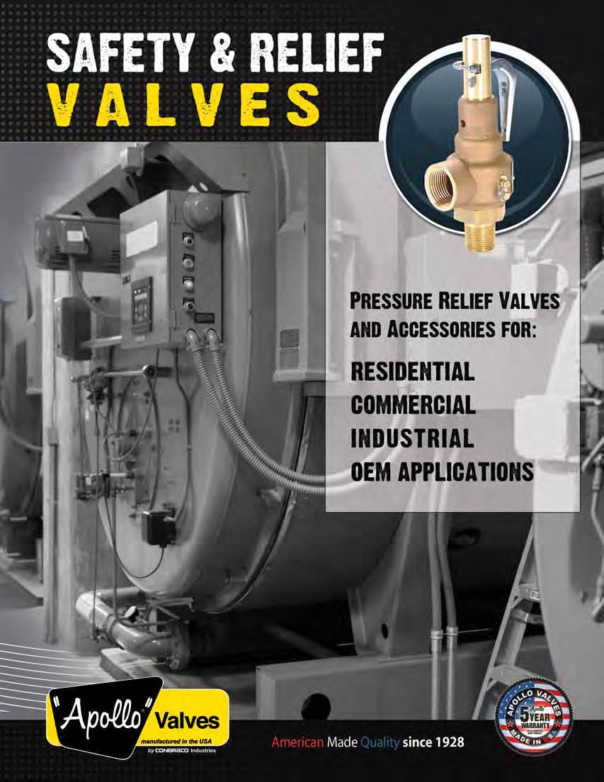
2 A history of Quality, Service and Innovation Now in its ninth decade, Conbraco Industries, Inc. is a leading manufacturer of flow control products for U.S. and international markets. The company s headquarters is based in Matthews, North Carolina with manufacturing plants and foundries located in Pageland and Conway, South Carolina. Conbraco has a history of new product development and innovation that dates back to the company s inception in Today, the Conbraco line of products is marketed under the Apollo Valves brand and includes: ball valves, butterfly valves, backflow prevention devices, water pressure reducing valves, mixing valves, safety relief valves, water gauges, strainers, actuation and ApolloXpress products. Conbraco s vertically integrated manufacturing ensures a consistency of production, testing, quality and availability. You can be assured that Conbraco flow control products will deliver long term reliability. All Conbraco plants are registered to ISO 9001:2008 quality standards. The Conbraco line continues to expand with new products, designs and advanced materials to better serve the needs of our customers. Markets served include: chemical processing, pulp and paper, petroleum, residential and commercial plumbing and heating, OEM, irrigation, water works, and fire protection. A long, successful history in safety and relief valves Conbraco has been designing and producing ASME safety and relief valves for eight decades. Its portfolio includes more than 30 models of valves carrying the ASME Section I, Section IV and Section VIII designations. These products are specified around the globe for use in boilers, sterilizers, air compressors and a broad spectrum of commercial, industrial and OEM applications. The company offers safety and relief valves with brass, bronze, cast iron, carbon steel and stainless steel body construction. Available in inlet sizes from 1 4 through 6, Conbraco valves are certified for steam, air/gas and liquid service, with set pressures up to 1,200 psi. As part of its total quality program, Conbraco provides 100 percent factory testing of safety and relief valves prior to shipment. It maintains a network of regional ASME certified setting stations that offer prompt deliveries as well as factory authorized sales, service and repair. Every Conbraco safety and relief valve represents our proud tradition of providing customers with real value and satisfying their needs with unmatched efficiency, consistency and speed. This catalog provides you with a full overview of the Conbraco safety and safety relief valve product line plus information on proper valve selection and application. If you have any questions, please don t hesitate to contact your nearest Conbraco factory representative, authorized setting station or Conbraco customer service.
3 table of contents PRODUCTS PAGE NO. Valve Selection Guide Series / Series Series Series... 12, Series... 13, Series , , Series Series Series C-400 & 18C-402X Series C-500 Series Series Series Series Drip Pan Elbows Series Equivalents and Conversion Factors Correction Factors Warranty Information European CE/PED Compliance Now Available! Several models of Apollo / Conbraco pressure relief valves listed in this catalog may now be furnished in compliance with the provisions of the European Pressure Equipment Directive 97/23/EC. These valves meet the essential safety requirements for Safety Hazard Category IV and Conformity Assessment Module H1. CE conformance is signified by the inclusion of the symbol on the valve nameplate. CE marking is an option and must be specified at the time of order placement. Please consult the factory for details For additional information, submittal sheets and manuals, visit 3
4 Pressure Relief Valve Selection Chart Model Material Inlet Sizes Inlet Sizes Connections Body / Trim Min / Max, in. Min / Max, mm. NPT Flanged CE/PED Available Set Pressures Min / Max, PSIG Set Pressures Min / Max, barg Temperature Max, F Temperature Max, C ASME Section I - Steam Power Boilers 19M Bronze / Brass 1/2-2 1/2 DN X X F C 19K Bronze / Brass 1/2-2 1/2 DN X X F C 19L Bronze / Stainless 1/2-2 1/2 DN X X F C 19S Bronze / Stainless 1/2-2 1/2 DN X X F C 29 Bronze / Brass 3/8-1 1/4 DN X X F C 119 Cast Iron / Stainless 1-1/2-6 DN X X X F C ASME Section IV - Low Pressure Steam Heating Boilers 12 Bronze / Brass 2-3 DN X F C Bronze / Brass 3/4 DN 20 X F C Bronze / Brass 1 DN 25 X F C Bronze / Brass 3/4 DN 20 X F C Bronze / Brass 1-1/4 DN 32 X F C Bronze / Brass 1-1/2 DN 40 X F C Bronze / Brass 3/4 DN 20 X F C Bronze / Brass 2-3 DN X F C ASME Section IV - Hot Water Heating & Supply Boilers Bronze / Brass 3/4 DN 20 X F C Bronze / Brass 3/4 DN 20 X F C Bronze / Brass 3/4 DN 20 X F C Bronze / Brass 3/4 DN 20 X F C , Bronze / Brass 3/4-2 DN X X F C , Bronze / Brass 3/4 DN 20 X F C Bronze / Brass 1/2 DN 15 X F C Bronze / Brass 3/4 DN 20 X F C 18C-400 Bronze / Brass 1/2-3/4 DN X F 98.9 C 18C-500 Bronze / Stainless 3/4-2 DN X F 98.9 C ASME Section VIII Air / Gases 15 Brass 1/4-1 DN 8-25 X X F C 19M Bronze / Brass 1/2-2-1/2 DN X X F C 19K Bronze / Brass 1/2-2-1/2 DN X X F C 19L Bronze / Stainless 1/2-2-1/2 DN X X F C 19S Bronze / Stainless 1/2-2-1/2 DN X X F C 29 Bronze / Brass 3/8-1-1/4 DN X X F C 119 Cast Iron / Stainless 1-1/2-6 DN X X X F C 510 Bronze / Brass 1/2-2 DN X X F C 520 Bronze / Stainless 1/2-2 DN X X F C 530 Steel / Stainless 1/2-2 DN X X X F C 540 Stainless / Stainless 1/2-2 DN X X X F C ASME Section VIII Steam Brass 3/4 DN 20 X X F C Brass 1/2 DN 15 X X F C 19M Bronze / Brass 1/2-2-1/2 DN X X F C 19K Bronze / Brass 1/2-2-1/2 DN X X F C 19L Bronze / Stainless 1/2-2-1/2 DN X X F C 19S Bronze / Stainless 1/2-2-1/2 DN X X F C 29 Bronze / Brass 3/8-1-1/4 DN X X F C 119 Cast Iron / Stainless 1-1/2-6 DN X X X F C 510 Bronze / Brass 1/2-2 DN X X F C 520 Bronze / Stainless 1/2-2 DN X X F C 530 Steel / Stainless 1/2-2 DN X X X F C 540 Stainless / Stainless 1/2-2 DN X X X F C ASME Section VIII Liquid 510 Bronze / Brass 1/2-2 DN X X F C 520 Bronze / Stainless 1/2-2 DN X X F C 530 CS / Stainless 1/2-2 DN X X X F C 540 Stainless / Stainless 1/2-2 DN X X X F C Non-Code, Vacuum & Miscellaneous Products , Low Pressure Air 2-3 DN X F C Vacuum Relief 2-3 DN X 8-30 HG mm. HG 400 F C Liquids 1/2 DN 15 X F 48.9 C Adj. Liquid Bypass 1/2 DN 15 X F 93.3 C , Calibrated Liquid Relief 1/2-3/4 DN X F 93.3 C Drip Pan Elbows Steam Discharge 3/4-8 DN X X N/A N/A 450 F C 4


 3/4F 1F 3.94 105 20-60 20 F 25 F 100 47.7 3/4 M 1 F 3.75 109 20-60 20 M 25 F 95 49.5 3/4 M 3/4 F 3.75 114 20-60 20 M 20 F 95 51.8 3/4 F 3/4 F 3.94 115 20-60 20 F 20 F 100 52.3 3/4 M 3/4 F 3.")
5 Hot Water Boiler Safety Relief Valves 10 Series Brass/bronze safety relief valves protect ASME Section IV hot water heating boilers and hydronic heating systems. High capacity design features corrosion resistant construction. Brass, satin or polished chrome finishes available ASME Section IV Inlet Size 3/4 - Outlet - 3/4 & 1 Factory set Pressure psi Maximum temperature service: 250 F Applications: Ideal for use with hot water boilers and hydronic heating systems. HV Section IV Heating Boilers Features: Pressures from 20 to 150 psig Registered in all Canadian provinces and territories, CRN #0G8547.5C Stainless steel springs standard /634 are ideal for use in various plumbing systems, commercial boiler applications and swimming pool heaters /417 are ideal for use in swimming pool heater applications Options: Model and are available with optional satin or polished chrome finish available in polished chrome only Dimensions and Weights Model Number Inlet NPT Size(in./mm.) Outlet NPT Certified Pressure Range psig Height (in./mm.) Wt./100 (lbs./kg.) 3/4F 1F F 25 F /4 M 1 F M 25 F /4 M 3/4 F M 20 F /4 F 3/4 F F 20 F /4 M 3/4 F M 20 F /4 M 3/4 F M 20 F /4 F 3/4 F F 20 F /4 M 3/4 F M 20 F /4 F 3/4 F F 20 F /4 M 3/4 F M 20 F /4 F 3/4 F F 20 F OEM For additional information, submittal sheets and manuals, visit 5
6 Hot Water Boiler Safety Relief Valves 10 series ASME Section IV Hot Water British thermal units per hour (Kilocalories per hour) at 10% overpressure. National Board Certified. Ratings are 90% of actual. US Customary Units Btu/Hr. Metric Units Kcal/Hr. Model No Model No Set Pressure psig Set Pressure barg 5* - 225, , * - 295, , , , , , , , , , , , , , , , , , , , , , , , , , , , , , ,035, , , ,000 1,007, ,115, , , ,000 1,087, ,200, , , ,000 1,166, ,000 1,246, ,000 1,325, ,000 1,405, ,027,000 1,484, ,564, ,643, ,723, ,802, ,882, ,961, ,041, ,120, ,199, ,279, ,358, ,438, ,517, ,597, * Pressure settings below 15 psi are non-asme Code. 6 P/N Suffix Key Exterior Finish Plain Brass Satin Chrome Set Pressure psig Polished Chrome Ordering Code: Use two-digit suffix number to indicate set pressure and body finish. Suffix for / models is actual set pressure in psig. EXAMPLE: / psig, satin chrome finish / psig (plain bronze finish only) NOTE: Model available in polished chrome finish only. All other models are furnished with plain bronze finish. Model and available with optional satin or polished chrome finish.


7 OEM Style Steam Safety Relief Valves and Series National Board capacity-certified safety valves; brass body with optional satin or polished chrome finish. Protects against excess pressure from thermal expansion and steam caused by failure of Btu input controls ASME Section VIII Sizes 1/2 and 3/4 Factory set pressures 15 to 60 F max National Board Certified Capacity Applications: Ideally suited for OEM applications such as steam carpet and jewelry cleaners, autoclaves, sterilizers, commercial pressure cookers, steam jacketed kettles, dental equipment, coffee makers and similar equipment. Features: Stainless steel springs Small physical size Discharge capacities to 725 lbs./hr. Soft seating for exceptional seat tightness Pressure settings 15 to 60 psig in polished chrome only ( P) CRN OG8547.5C, registered in all Canadian provinces and territories More descriptive model numbering system UV Section VIII Pressure Vessels Options: (Model Only) Satin or polished chrome finish Stainless steel wetted trim BSP pipe connections CE/PED compliance P/N Suffix Key Set *Certified Capacities Pressure psig lbs.hr. lbs.hr * ASME (UV) Rating 90% of actual capacity at 10% accumulation. Capacity in lbs. of saturated steam per hour. Dimensions and Weights Model Number Inlet NPT Size (in./mm.) Outlet NPT Set Pressure Range psig Height (in./mm.) Wt./100 (lbs./kg.) 3/4 M 3/4 F /2 M 1/2 F Model numbering system 10 - X -X -XX -X model and size (in.) finish Set pressure options 512 = 1/2 x 1/2 B = Plain Brass Set Pressure in PSIG B = BSPP connections 322 = 3/4 x 3/4 S = Satin Chrome (2 Digits) CE = PED/CE P = Polished Chrome S = Stainless Steel trim V = Viton Seat X = Blank Outlet not threaded EXAMPLE: P-20 3/ psig, polished chrome finish. NOTE: Model available in polished chrome finish only. Valves may be set for any pressure between 15 and 60 psig. For additional information, submittal sheets and manuals, visit 7

8 OEM Style Steam Safety Relief Valves series Materials Item Component Material 1 Nozzle Brass ASTM B-16 2 Body Brass ASTM B-16 3 Nameplate Aluminum 4 Drive Screw Steel, Zinc Plated 5 Handle Steel, Zinc Plated 6 Cotter Pin Steel, Zinc Plated 7 Stem Brass ASTM B-16 8 Spring Stainless Steel 9 Spring Washer Brass ASTM B Disc Brass ASTM B Seat Teflon Faced EPDM 12 Washer Brass ASTM B series Materials Item Component Material 1 Nozzle Brass ASTM B-16 2 Body Brass ASTM B-16 3 Nameplate Aluminum 4 Drive Screw Steel, Zinc Plated 5 Pull Ring Steel, Zinc Plated 6 Cap Brass ASTM B-16 7 Disc Assembly Brass, Silicone 8 Spring Stainless Steel 9 Spring Washer Brass ASTM B-16 4 Model available with optional stainless steel wetted trim. Nozzle, disc holder and disc washer are type 316 stainless steel

9 High Capacity Safety Relief Valves for Hot Water Heating Boilers series High-capacity heating system valves with female inlet and standard or expanded female outlet. Elevated seat for drainage of water away from seat area. Entire pressure range is National Board capacity certified. ASME Section IV Inlet Sizes 3/4 to 2 Factory set pressures from psig Maximum temperature service 250 F Applications: Hot water heating boilers and hot water supply systems HV Section IV Heating Boilers Features: High Btu capacity rating Silicone seat Fabric reinforced molded diaphragm isolates spring from water at all times Bronze body and spring cage Registered in Canadian provinces and territories CRN #0G8547.5C Protects against excessive water pressure due to failure of controls to regulate Btu input P/N Suffix Key Set Pressure psig D Suffix Set Pressure psig Suffix C A B Dimensions and Weights Model Number Size(in./mm.) Certified Dimensions (in./mm.) Pressure Wt./100 Inlet Outlet Range (lbs./kg.) NPT NPT psig A B C D 3/4F 3/4F /4F 1 F F 1F F 1-1/4F /4F 1-1/4F /4F 1-1/2F /2F 1-1/2F /2F 2F F 2F F 2-1/2F Ordering Code: Use two-digit suffix number to indicate Inlet x Outlet size and set pressure. EXAMPLES: x 1-1/ set 60 psig x set 30 psig For additional information, submittal sheets and manuals, visit 9

10 High Capacity Safety Relief Valves for Hot Water Heating Boilers D series C A B Materials Item Component Material 1 Body Bronze Alloy C Seat Insert Brass ASTM B-16 3 Seat Silicone 4 Disc Brass ASTM B-16 5 Diaphragm Fabric Reinforce EPDM 6 Stem Nut Steel Plated 7 Spacer Silicone 8 Cap Bronze Alloy C Spring PLAted ASTM A Spring Washer AISI 12L14 Steel 11 Adj. Screw Brass ASTM B Nameplate Aluminum 13 Lift Washer Steel Plated 14 Handle Rivet Steel Plated 15 Lift Handle Steel Plated 16 Stem Nut Steel Plated 17 Diaphragm Ret. Steel Plated ASME Section IV Hot Water British thermal units per hour (Kilocalories per hour) at 10% overpressure. National Board Certified. Ratings are 90% of actual. US Customary Units Btu/Hr. Metric Units Kcal/Hr. Model No /4 x 3/ x /4 x 1-1/ /2 x 1-1/ x 2 Model No x x x x x 50 Set Pressure psig Set Pressure barg , ,000 1,515,000 2,061,000 3,397, ,000 1,030,000 1,782,000 2,424,000 3,996, , ,000 1,185,000 2,049,000 2,788,000 4,595, , ,000 1,339,000 2,316,000 3,151,000 5,193, , ,000 1,493,000 2,583,000 3,514,000 5,792, , ,018,000 1,648,000 2,850,000 3,878,000 6,391, , ,113,000 1,802,000 3,117,000 4,241,000 6,990, ,070 1, ,209,000 1,956,000 3,384,000 4,604,000 7,589, ,161 1, ,304,000 2,111,000 3,651,000 4,968,000 8,188, ,253 2, ,399,000 2,265,000 3,918,000 5,331,000 8,786, ,344 2, ,495,000 2,420,000 4,185,000 5,694,000 9,385, ,055 1,436 2, ,590,000 2,574,000 4,453,000 6,058,000 9,984, ,123 1,528 2, ,686,000 2,728,000 4,720,000 6,421,000 10,583, ,190 1,619 2, ,781,000 2,883,000 4,987,000 6,784,000 11,182, ,258 1,711 2, ,876,000 3,037,000 5,254,000 7,148,000 11,780, ,325 1,803 2, ,972,000 3,192,000 5,521,000 7,511,000 12,379, ,393 1,894 3, ,067,000 3,346,000 5,788,000 7,874,000 12,978, ,560 1,986 3, ,162,000 3,500,000 6,055,000 8,238,000 13,577, ,527 2,076 3, ,258,000 3,655,000 6,322,000 8,601,000 14,176, ,594 2,169 3, ,353,000 3,809,000 6,589,000 8,964,000 14,775, ,662 2,261 3, ,449,000 3,963,000 6,856,000 9,327,000 15,373, ,729 2,352 3, ,544,000 4,118,000 7,123,000 9,691,000 15,972, ,039 1,796 2,444 4, ,639,000 4,272,000 7,390,000 10,054,000 16,571, ,077 1,864 2,536 4, ,735,000 4,427,000 7,657,000 10,417,000 17,170, ,116 1,931 2,627 4, ,830,000 4,581,000 7,924,000 10,781,000 17,769, ,155 1,998 2,719 4, ,925,000 4,735,000 8,191,000 11,144,000 18,368, ,194 2,066 2,811 4, ,021,000 4,890,000 8,458,000 11,507,000 18,966, ,233 2,133 2,902 4, ,116,000 5,044,000 8,725,000 11,871,000 19,565, ,272 2,200 2,994 4, ,212,000 5,199,000 8,992,000 12,234,000 20,164, ,311 2,268 3,085 5, ,307,000 5,353,000 9,260,000 12,597,000 20,763, ,350 2,335 3,177 5,
11 High Capacity Safety Relief Valves for Hot Water Heating Boilers series ASME Section IV Hot Water British thermal units per hour (Kilocalories per hour) at 10% overpressure. National Board Certified. Ratings are 90% of actual. US Customary Units Btu/Hr. Metric Units Kcal/Hr. Model No /4 x x 1-1/ /4 x 1-1/ /2 x x 2-1/2 Model No x x x x x 65 Set Pressure psig Set Pressure barg ,000 1,027,000 1,777,000 2,417,000 3,984, , ,000 1,208,000 2,090,000 2,843,000 4,686, , ,000 1,389,000 2,403,000 3,270,000 5,389, , ,000 1,570,000 2,716,000 3,696,000 6,091, , ,082,000 1,751,000 3,030,000 4,122,000 6,793, ,040 1, ,194,000 1,933,000 3,343,000 4,548,000 7,496, ,147 1, ,306,000 2,114,000 3,656,000 4,974,000 8,198, ,254 2, ,418,000 2,295,000 3,969,000 5,400,000 8,900, ,362 2, ,529,000 2,476,000 4,283,000 5,826,000 9,603, ,080 1,469 2, ,641,000 2,657,000 4,596,000 6,252,000 10,305, ,159 1,577 2, ,753,000 2,838,000 4,909,000 6,679,000 11,007, ,238 1,684 2, ,865,000 3,019,000 5,222,000 7,105,000 11,710, ,317 1,792 2, ,977,000 3,200,000 5,535,000 7,531,000 12,412, ,396 1,899 3, ,089,000 3,381,000 5,849,000 7,957,000 13,114, ,475 2,007 3, ,201,000 3,562,000 6,162,000 8,383,000 13,817, ,554 2,114 3, ,313,000 3,743,000 6,475,000 8,809,000 14,519, ,633 2,222 3, ,424,000 3,924,000 6,788,000 9,235,000 15,221, ,712 2,329 3, ,536,000 4,105,000 7,101,000 9,661,000 15,924, ,035 1,791 2,437 4, ,648,000 4,286,000 7,415,000 10,088,000 16,626, ,081 1,870 2,544 4, ,760,000 4,468,000 7,728,000 10,514,000 17,328, ,127 1,949 2,652 4, ,872,000 4,649,000 8,041,000 10,940,000 18,031, ,172 2,028 2,759 4, ,984,000 4,830,000 8,354,000 11,366,000 18,733, ,218 2,107 2,866 4, ,096,000 5,011,000 8,668,000 11,792,000 19,435, ,264 2,186 2,974 4, ,207,000 5,192,000 8,981,000 12,218,000 20,138, ,309 2,265 3,081 5, ,319,000 5,373,000 9,294,000 12,644,000 20,840, ,355 2,344 3,189 5, ,431,000 5,554,000 9,607,000 13,070,000 21,543, ,401 2,423 3,296 5, ,543,000 5,735,000 9,920,000 13,497,000 22,245, ,446 2,502 3,404 5, ,655,000 5,916,000 10,234,000 13,923,000 22,947, ,492 2,581 3,511 5, ,767,000 6,097,000 10,547,000 14,349,000 23,650, ,538 2,660 3,619 5, ,879,000 6,278,000 10,860,000 14,775,000 24,352, ,583 2,739 3,726 6,141 For additional information, submittal sheets and manuals, visit 11


12 Low Pressure Steam Heating Boiler Safety Valves series Medium capacity safety valves protect ASME Section IV low pressure steam heating boilers. Cast bronze, full nozzle design features PTFE faced elastomer soft seating for dependable operation. Ideal for OEM applications. ASME Section IV Sizes 2, 2-1/2 and 3 Factory set pressures 5-15 psi Applications: Medium and large commercial and industrial steam heating and processing boilers. HV Section IV Heating Boilers Features: All bronze construction PTFE-coated O-ring seat seal 3/8 NPT side tapping for drain Rust-proofed steel spring Top guided, high capacity design Registered in all Canadian provinces and territories, CRN #0G8547.5C National Board certified at 15 psig D C B A Dimensions and Weights Size (in./mm.) Dimensions (in./mm.) Model Wt./Ea. Inlet Outlet Number (lbs./kg.) NPT NPT A B C D 2M 2F /2M 2-1/2F M 3F NOTE: See Capacities page Materials Item Component Material 1 Nozzle Bronze ASTM B584 2 Body Bronze ASTM B584 3 O-ring Teflon Coated EPDM 4 Drive Screw AISI 1010 Plated CR Steel 5 Nameplate Aluminum 6 Handle Assembly Steel, Plated 7 Disc Brass ASTM B Stem Brass ASTM B Spring Stainless Steel 12 Spr. Washer AISI 1010 Plated CR steel 13 Stem Nut Brass ASTM B Retainer Ring Brass ASTM B Guide Brass ASTM B Ordering Code: Use two-digit suffix number to indicate set pressure and body finish. P/N Suffix key Set Pressure psig Suffix EXAMPLE: Series set 15 psig


 Dimensions (in./mm.) Model Wt.")
13 Low Pressure Steam Heating Boiler Safety Valves 13 series ASME Section IV bronze safety valves protect small to medium low pressure steam heating boilers. Three design configurations feature top guiding and raised seating area for extended service life. Available top and side discharge models ASME Section IV Sizes 3/4-1-1/2 Factory set pressure 5 to 15 psi Applications: Low pressure steam heating and supply boilers. HV Section IV Heating Boilers C B A Features: Flat seat, PTFE faced disc for positive seal Standard set pressure of 15 psig Positive drainage of condensate from seat area No is top outlet discharge Registered in all Canadian provinces and territories, CRN #0G8547.5C ASME and National Board certified at 15 psig Options: Satin or polished chrome finishes D C B A B Dimensions and Weights Size (in./mm.) Dimensions (in./mm.) Model Wt./100 Inlet Outlet Number (lbs./kg.) NPT NPT A B C D /4 M Top /4 M 3/4 F M 1 F /4 M 1-1/2 F /2 M 2 F /4 M 3/4 F /4 F 3/4 F NOTE: See Capacities page 15 Model numbering system 13 - XXX -X -XX -X model finish set pressure options 101= 3/4 M x Top B = Plain Brass Set Pressure in PSIG A = Air Service (Non-ASME) 211 = 3/4 M x 3/4 F S = Satin Chrome* (2 Digits) 202 = 1 M x 1 F P = Polished Chrome* 213 = 1-1/4 M x 1-1/2 F 214 = 1-1/2 M x 2 F 511 = 3/4 M x 3/4 F 512 = 3/4 F x 3/4 F D C A EXAMPLE: B15 3/ set at 15 psig * Available on select models only For additional information, submittal sheets and manuals, visit 13

14 Low Pressure Steam Heating Boiler Safety Valves series ASME Section IV Factory set pressures from 5 to 15 psig. Sizes 2, 2-1/2 and 3. HV Applications: Section IV The 14 Series is an ASME Section IV high capacity steam safety Heating Boilers valve for use with medium and large size commercial and industrial heating boilers. Features: One piece body, all bronze construction Rust proofed steel spring Chrome plated seat, PTFE coated disc PTFE coated EPDM O-ring for positive seal 3/8 NPT side tapping for drain connection Valves are capacity certified by the National Board at 15 psig only, in accordance with ASME Boiler and Pressure Vessel Code Section IV Registered in all Canadian provinces and territories, CRN #0G8547.5C Options: Test gag available to prevent the valve from opening during hydrostatic testing of the boiler. To specify gag option, add G to suffix. A B Dimensions and Weights Size (in./mm.) Dimensions (in./mm.) Model Wt./Ea. Inlet Outlet Number (lbs./kg.) NPT NPT A B C D 2M 2F M 50F /2M 2-1/2F M 65F M 3F M 80F NOTE: See Capacities page 15 D C Ordering Code: Use model number and two digit suffix number to indicate size and set pressure. P/N Suffix key Set Pressure psig Suffix EXAMPLE: /2 valve set at 15 psi Note: ASME IV and NB certified capacities at 15 psi only Valves may be set for any pressure between 5 and 15 psi. Consult factory for set pressures not listed. To specify test gag option add G to suffix. 14
15 Low Pressure Steam Heating Boiler Safety Valves US Customary Units Lbs./Hr. Model No. (in.) x /2 x 2-1/ x /4 capacities ASME Section IV Steam Pounds per hour (Kilograms per hour) saturated steam at 33-1/3% overpressure. National Board Certified. Ratings are 90% of actual x /4 x 3/ /4 x 1-1/ /2 x /4 x 3/ x /2 x 2-1/2 Set Pressure psig 5* 1,439 2,043 2, , ,815 2,695 3,944 10* 1,969 2,786 3, , ,483 3,686 5, ,500 3,529 4, ,200 1, ,150 4,676 6,843 Metric Units Kg./Hr. Model No. (mm.) 12, 13 and series x x x x x20 Set Pressure barg , ,222 1, ,264 1, ,126 1,672 2, ,134 1,601 1, ,429 2,121 3,103 *ASME Section IV and NB certified capacities at 15 psi only. Valves may be set for any pressure between 5 and 15 psi. Consult factory for set pressures not listed x x x x x x x 80 For additional information, submittal sheets and manuals, visit 15
16 Low Pressure Air Relief Valves and series High volume air relief valves designed for low pressure/high volume air and gas service. Rugged bronze construction features elastomer soft seating and TFE coated discs for dependable operation. Inlet sizes 2, 2 1/2 and 3 Factory set pressures 4 to F max. A B Applications: Non-ASME code air and gas service Low pressure, high volume blowers and compressors Bulk hauling tanks, trailers and rail cars Powdered solids / bulk handling Pneumatic conveying equipment w/lift Lever C Features: Vibration resistant soft seat is standard Stainless steel spring One piece corrosion resistant bronze body design High flow top-guided design Options: Model with test lever Model with plain cap, weather resistant sealed body Air Relief CAPACity: See page 19 C A B Dimensions and Weights Model Number 14-X05 14-X06 14-X07 Size (in./mm.) Dimensions (in./mm.) A B C Wt./Ea. (lbs./kg.) 2 x /2 3-1/ M x 50F /2 x 2-1/2 3-1/2 7-5/8 3-1/ M x 65F x 3 4-1/8 8-3/4 3-7/ M x 80F Plain Cap Model numbering system /500 Series Air Relief Valves 14 -X -XX -X series number body/cap style and service inlet connection relief pressure 14 = Base Model No. 4 = Air Relief, with Test Lever 05 = 2 NPT Set Pressure in PSIG 5 = Air Relief, Plain Cap 06 = 2 1/2 NPT (2 Digits) 07 = 3 NPT EXAMPLES: /2 14 Series air relief valve set at 12 psig, with lift lever air relief valve set at 8 psig, with sealed cap 16
17 Vacuum Relief Valves series High flow vacuum relief valves feature one piece cast bronze bodies. Teflon coated discs and elastomer soft seating provide accurate and dependable operation. Connect vacuum source here B Connection sizes 2, 2 1/2 and 3 Relief settings 8 to F max. Applications: High volume vacuum systems Bulk hauling tanks and trailers Powdered solids / bulk handling Pneumatic conveying equipment C A Features: Weather resistant construction Elastomer soft seat is vibration resistant Stainless steel spring One piece corrosion resistant bronze body design High capacity top-guided design TFE / chrome plated internals VACUUM Air Relief CAPACity: See page 19 Dimensions and Weights Model Number Size (in./mm.) Dimensions (in./mm.) A B C Wt./Ea. (lbs./kg.) 2 x /2 3-1/ M x 50F /2 x 2-1/2 3-1/2 7-5/8 3-1/ M x 65F x 3 4-1/8 8-3/4 3-7/ M x 80F Model numbering system X -VXX series number body/cap style and service inlet connection relief pressure 14 = Base Model No. 6 = Vacuum Relief 05 = 2 NPT Vacuum Relief 06 = 2 1/2 NPT 07 = 3 NPT Setting, HG V Prefix + Inches Mercury ( V + 2 Digits) EXAMPLE: V14 3 Vacuum relief valve set at 14 Hg For additional information, submittal sheets and manuals, visit 17
 3 Spring Stainless Steel 4 Adjusting Screw Brass ASTM B-16 5 Cap Screw (4) Steel (Plated) 6 Spring Washer Brass ASTM B-16 7 Cap Bronze ASTM B-584 8 Seat-O-Ring Silicone 9 Seat Insert")
 17 Lift Lever Steel (Plated) 18 Roll Pin Steel (Plated) 19 Plug Brass ASTM B-16 20 Plug Brass ASTM B-16 21 Cap Seal O-Ring Silicone 5 20 1 8 2 7 21 11 14 12 6 4 3 13 15 10 19 9 14-500 &")
18 Low Pressure Air and Vacuum Relief Valves , and series Materials Item Component Material 1 Nameplate Aluminum 2 Drivescrews (2) Steel (Plated) 3 Spring Stainless Steel 4 Adjusting Screw Brass ASTM B-16 5 Cap Screw (4) Steel (Plated) 6 Spring Washer Brass ASTM B-16 7 Cap Bronze ASTM B Seat-O-Ring Silicone 9 Seat Insert Brass ASTM B Disc Bronze ASTM B Body Bronze ASTM B Friction Ring EPDM 13 Stem Nut Brass ASTM B Stem Brass ASTM B Retaining Ring Steel (Plated) 16 Lift Washer Steel (Plated) 17 Lift Lever Steel (Plated) 18 Roll Pin Steel (Plated) 19 Plug Brass ASTM B Plug Brass ASTM B Cap Seal O-Ring Silicone &
19 Air Relief Valves and series US Customary Units SCFM Air Ordering Suffix Model No. Size (in.) Area (in. 2 ) x /2 x 2-1/ x Set Pressure psig Non-Code Air Relief Capacities Standard cubic feet per minute (Normalized cubic meters per hour) of air at 10% overpressure. Metric Units Nm 3 /Hr. Air Model No. Size (mm.) Area (cm 2 ) x x x Set Pressure barg series US Customary Units SCFM Air Ordering Suffix Model No. Size (in.) Area (in. 2 ) x /2 x 2-1/ x Relief Setting (in. Hg) V V V V V V V V V V V Vacuum Air Relief Capacity. Standard cubic feet per minute (normalized cubic meters per hour) of air at 10% overpressure. Metric Units Nm 3 /Hr. Air Model No. Size (mm.) Area (cm 2 ) x x x Relief Setting (mm. Hg) For additional information, submittal sheets and manuals, visit 19


20 Air Relief Valves 15 series Rugged design 15 Series air relief valves provide dependable overpressure protection at an economical price. Top guided design features brass construction and resilient seating for superior performance. Widely used by OEM s and for aftermarket replacement. ASME Section VIII Sizes 1/4 to 1 Factory set pressures from 15 to 250 psi Maximum Temp. 325 F Applications: Ideal for a wide range of air and inert gas applications UV Section VIII Pressure Vessels including compressors, intercoolers, dryers, receivers, control and instrument air lines, and pressurized systems and equipment. A Features: National Board certified 15 psig through 250 psig Stainless steel springs Viton O-ring seat Registered in all Canadian provinces and territories: CRN #0G8547.5C ASTM B16 Brass Body RoHS Compliant Materials European pressure equipment directive compliant option (CE/PED) B Dimensions and Weights Model Number Inlet Dimensions (in./mm.) Size (in./mm.) A B Wt./100 (lbs./kg.) 1/4 NPT /8 NPT /2 NPT /4 NPT NPT Materials Item Component Material 1 Nozzle ASTM b-16 Brass 2 Body ASTM b-16 Brass 3 Nameplate Aluminum 4 Pull Ring Pltd. aisi 1018 crs 5 Disc/Stem ASTM b-16 Brass 6 Seat Viton 7 Cap ASTM b-16 Brass 8 Spring ASTM a-227 Steel 9 Inst. Tag Paper 10 Lead Seal Lead Model numbering system 15-XXX -X -XXX -XX Model and Size (in.) finish set pressure options 112 = 1/4 NPT B = Plain Brass Set Pressure in PSIG CE = PED/CE 20 EXAMPLE: B Series 165 psig. 115 = 3/8 NPT Q = Performance 117 = 1/2 NPT (Calibration) Test 118 = 3/4 NPT Reports 119 = 1 NPT
21 Air Relief Valves 15 series US Customary Units SCFM Air Model No. Size (in.) / & 117 3/8 & 1/ / Set Pressure psig , , , , , , , , , , , , , , , , , , , , , , , , , ,964 ASME Section VIII - Air Standard cubic feet per minute (Normalized cubic meters per hour) of air at 10% overpressure. National Board Certified. Ratings are 90% of actual. Metric Units Nm 3 /Hr. Air Model No. Size (mm) & & Set Pressure barg , , , , , , , , , , , , , , , , , , ,005 2, ,035 2, ,064 2, ,093 2, ,122 2, ,151 2, ,180 2, ,209 2, ,238 2, ,267 2, ,296 2, ,325 2, ,353 2, ,382 2, ,411 2, ,440 2, ,469 3, ,498 3, ,527 3,157 For additional information, submittal sheets and manuals, visit 21

22 General Purpose Pressure Relief Valves Economical relief valves for general purpose non-code overpressure protection and bypass relief applications. Applications include liquid bypass or thermal expansion relief of well pumps, tanks, fire protection systems and all types of water or liquid piping systems. Not intended for steam service series Pressure relief valves relieve excess pressure in cold water supply systems, storage tanks, well pumps. Also suitable for air, oil and other non-hazardous liquids. Features: Standard pressure settings from 50 to 175 psi Cast bronze body, stainless steel springs Silicone soft seat ensures seat tightness, extended service life All valves are 100% factory tested Maximum recommended service temperature 120 F Lead Free Option, Model 16LF C A B Dimensions and Weights Model Number LF Model Number LF LF-203 Inlet Dimensions (in./mm.) Size (in./mm.) A B C Wt./100 (lbs./kg.) 1/2 M X 1/2 F M x 15 F /4 M x 1/2 F M x 15 F Ordering Code: Use two-digit suffix number to indicate set pressure and body finish. P/N Suffix key Set Pressure psig Suffix EXAMPLE: /2 model 100 psi. NOTE: Valves may be set for any pressure between 30 and 180 psi. Consult factory for pressure settings not shown. 22


23 General Purpose Liquid Relief Valves series Adjustable relief valves protect equipment by providing low volume liquid relief or bypass control. Excess volume may be discharged back to the low pressure source. Ideal for agricultural sprayers and simple commercial or industrial pressurized systems. A B Features: Adjustable relief settings, in two ranges to 600 psi Cast bronze body, stainless steel springs Choice of Nitrile (Buna) or PTFE soft seats Knurled locknut locks pressure adjustment Viton stem seal, polypropylene body gasket Maximum recommended service temperature 200 F Dimensions and Weights Model Number Inlet Size (in./mm.) Relief Range /2 M X 1/2 F M x 15 F Seat Material Nitrile PTFE Dimensions (in./mm.) A B C Wt./100 (lbs./kg.) C & series Calibrated pressure relief valve allows for in-line pressure adjustments without the need for a pressure gauge. Provides static overpressure protection for liquid filled systems such as well pumps, tanks, fire protection systems. A B Features: Choice of 1/2 or 3/4 inlet connection Factory preset at 100 psi Pressure range 50 to 175 psi, calibrated in 25 psi increments Cast bronze body, stainless steel spring Silicone soft seat, EPDM cap seal Maximum recommended service temperature 200 F Dimensions and Weights Model Number Inlet Size (in./mm.) 1/2 M X 1/2 F 15 M x 15 F 3/4 M X 1/2 F 20 M x 15 F Dimensions (in./mm.) A B C Wt./100 (lbs./kg.) C For additional information, submittal sheets and manuals, visit 23

24 Pressure Only Hot Water Relief Valves series series pressure only relief valves are engineered to protect against excessive pressure buildup due to thermal expansion in hot water supply systems. Both models are CSA certified to ANSI Z21.22 Relief Valves for Hot Water Supply Systems. In addition the is design certified to ASME Section IV for hot water relief. B A Connection sizes 1/2 (model ) and 3/4 (model ) CSA certified to ANSI Z21.22 Pressure settings 75 through F max. ASME Section IV Hot Water, model only Applications: HV Model : overpressure protection of domestic tankless water heaters. Also ideal for protecting plumbing and well systems, small liquid filled vessels and similar equipment from thermal expansion or pressure surges. Model : as above plus suitable for ASME Section IV hot water heating and supply boilers and storage tanks C Features: Cast bronze body, stainless steel springs Soft seat for durability, extended service life Conforms to HUD / FHA requirements CSA certified to ANSI Z21.22 ASME Section IV hot water, model CSA B-51, CRN 0G8547.5C Dimensions and Weights Model Number Inlet Size CSA Capacity ASME Dimensions (in./mm.) (in./mm.) Rating Capacity Wt./100 Rating A B C (lbs./kg.) 1/2 M X 1/2 F , M X 15 F /4 M X 3/4 F See table , M X 20 F below Ordering Code: Use model number and two-digit suffix number to indicate size and set pressure. P/N Suffix key Set Pressure psig Suffix Btu/hr. ASME Sec. IV , , , , EXAMPLES: /2 model psig /4 model psig. NOTE: Valves may be set for any pressure between 70 and 175 psi. Consult factory for pressure settings not shown. ASME Section IV certified model only, pressure settings 75 to 150 psig. 24


25 Water Heater T&P Relief Valves 18C-400 and 18C-402X series Automatic temperature and pressure relief valves feature unique non-metallic coating which protects the element against galvanic and electromechanical corrosion by isolating it from the heated water. This coating is electrostatically applied for uniform coverage, then thermobonded, resulting in optimum adhesion for extended service life. CSA design certified at all settings to ANSI Z ASME Section IV rated at 125 and 150 psig settings for 3/4 NPT only. C B A 18C-400 Applications: Temperature and pressure protection for hot water heaters and storage tanks. Features: Meets HUD/FHA requirements Cast bronze body, stainless steel spring Rated 210 F maximum Registered in all Canadian provinces and territories ASME capacity certified to 500,000 Btu/hr. HV Section IV Heating Boilers Options: Model 18C-402X features a body inlet extended 2 for insulated vessels. C B A 18C-402X Extended Shank Dimensions and Weights Model Number 18C C C C-402X Size (in./mm.) Element Length (in./mm.) CSA Capacity Rating Btu/HR Dimensions (in./mm.) A B C Wt./100 (lbs./kg.) 1/2 M x 1/2 F 1.44, 3 & 8" , M x 15 F 37, 76 & /4 M x 3/4 F , M x 20 F /4 M x 3/4 F 3 & , M x 20 F 76 & /4 M x 3/4 F 3" , M x 20 F Ordering Code: Use model number and two-digit suffix number to indicate size and set pressure. P/N Suffix key - model 18C-401 Set Pressure psig Coated Element Length (in.) P/N Suffix key - model 18C-402X Set Pressure psig Coated Element Length (in.) P/N Suffix key - model 18C-402 Set Coated Element Length (in.) Pressure psig Example: 18C-402X-38 3/4 model 18C-402X set 150 psig with 3 element Example: 18C /4 model 18C-402 set 150 psig with 3 element For additional information, submittal sheets and manuals, visit 25

26 Bronze High Capacity Commercial T&P Valves 18C series The Apollo 18C-500 Series bronze automatic temperature and pressure relief valves are used for high capacity protection of commercial hot water heaters and storage tanks. 26 Features: ASME Section IV certified capacity 3/4 through 2 NPT connections CSA Listed and certified to ANSI Z and 150 psig set pressures at 210 F max Coated element protects against corrosion SS elements (1-1/2 and 2 ) ASME Section IV heating boilers Canadian registration number CSA- 0G1438.6C Dimensions and Weights Part Number Size (in.) Element Length (in.) Inlet Type Inlet Size (in./mm.) Dimensions (in./mm.) A B C 3/4 M x 3/4 FNPT (20) (40) (88) (64) 3/4 F x 3/4 FNPT (20) (40) (88) (60) 1 M x 1 FNPT (25) (40) (88) (60) 1 F x 1 FNPT (25) (40) (88) (54) 1-1/4 M x 1 FNPT (32) (44) (110) (49) 1-1/2 M x 1-1/2 FNPT (40) (63) (148) (43) 2 M x 1-1/2 FNPT (50) (63) (148) (66) CSA Capacity Rating Btu/HR *ASME Cap. Rating BTU/HR 18C / M 185,000 1,619,000 18C / M 185,000 1,912,000 18C / M 205,000 1,619,000 18C / M 205,000 1,912,000 18C / M 205,000 1,619,000 18C / M 205,000 1,912,000 18C / F 185,000 1,619,000 18C / F 185,000 1,912,000 18C / F 205,000 1,619,000 18C / F 205,000 1,912,000 18C / F 205,000 1,619,000 18C / F 205,000 1,912,000 18C M 500,000 1,825,000 18C M 500,000 2,155,000 18C M 500,000 1,825,000 18C M 500,000 2,155,000 18C F 750,000 3,070,000 18C F 750,000 3,625,000 18CLF F 750,000 3,625,000 18C F 750,000 3,070,000 18C F 750,000 3,625,000 18C /4 x M 750,000 3,070,000 18C /4 x M 750,000 3,625,000 18C / F 1,200,000 5,125,000 18C / F 1,200,000 6,050,000 18C x 1-1/ M 1,200,000 5,125,000 18C x 1-1/ M 1,200,000 6,050,000 * National Board certified capacity per ASME Section IV-Heating Boilers Dimensions and Weights Model Number 18C511 18C512 18C521 18C522 18C531 18C542 18C551 HV Section IV Heating Boilers

27 Bronze Safety Valves For Steam, Air and Gas Service 19 series A dependable cast bronze high capacity safety valve ideal for use on all types of boilers, piping systems and unfired pressure vessels. This rugged design features top guided alignment for enhanced performance and reliability. Other features include optional metal seating, optional stainless steel wetted trim in all sizes, and a new, more descriptive model numbering system. Flow ratings are National Board certified in accordance with ASME sections I and VIII. Soft Seat Design Model 19K - Brass Model 19L - Stainless seat detail Metal to Metal Seat Design Model 19M - Brass Model 19S - Stainless ASME Section I and VIII Sizes 1/2 through 2-1/2 Factory set pressures 5 to 300 psig Maximum temperature is 406 F, 422 F for model 19S Applications: Overpressure protection of steam boilers, sterilizers, distillers, cookers, and pressure reducing stations. Pneumatic conveying equipment, air compressors, receivers and dryers. Steam, air and gas accumulators, pressure vessels and pressure piping systems. Features: Wide wrenching hex for easier, faster installations Stainless steel springs are standard Choice of Teflon or metal-to-metal seating Teflon PFA seat resists corrosive boiler chemicals and excessive vibration High-capacity full nozzle design available in six orifice sizes Two control rings for maximum performance and adjustability Short tuned blow down minimizes product loss Tapped body drain allows piping of condensate safely away from equipment Reduced repair costs: soft seat easily replaced Registered in all Canadian provinces under CSA B51 CRN OG8547.5C Options: Choice of Teflon or metal to metal seating Steam set pressures to F (Model 19S, stainless steel trim) 316 stainless steel wetted trim available for all sizes Anti-vibration dampened lifting lever Oxygen cleaning European Pressure Equipment Directive compliant option (CE/PED) V Section I Power Boilers UV Section VIII Pressure Vessels 4 trim styles to choose from Series 19K 19M 19L 19S Trim Brass Brass SS SS Seat Teflon Metal to Metal Teflon Metal to Metal Max. Set - Steam Max. Set - Air/Gas Max. Temperature 406 F 406 F 406 F 422 F Teflon is a registered trademark of DuPont. 19 Series Model Numbering System 19M D C K 165 A base model number orifice letter inlet size (in.) NPT asme code and service set pressure in psi special options 19K = Brass Trim/Teflon Seat D C = 1/2 A = Sect. I Steam A = Anti-vibration trim 19M = Brass Trim/Metal Seat E D = 3/4 K = Sect. VIII Air CE = CE/PED Compliant 19L = Stainless Trim/Teflon Seat F E = 1 L = Sect. VIII Steam Q = Performance 19S = Stainless Trim/Metal Seat G F = 1-1/4 N = Non-Code Air (Calibration) test report H G = 1-1/2 P = Non-Code Steam X = Oxygen cleaning J H = 2 * Other suffixes - factory issued J = 2-1/2 For additional information, submittal sheets and manuals, visit 27

 Brass Brass 7 Guide Ring Brass Brass 8 Disc Brass Stainless Steel 9 Guide Ring Screw Brass Brass 10 Nozzle Ring Screw Brass Brass 11 Seat")
28 B Bronze Safety Valves A series Materials C 19 Series 12 Materials 19 series with option a anti-vibration trim Item Component Material 1 Friction Clip (4) Steel Plated 2 Extension Spring Stainless Steel 3 Cap Lock Screw Stainless Steel Note: Preparation includes threadlocking of all internal threaded connections Item Component Material 19K, 19M Material 19L, 19S 1 Cap Brass Brass 2 Stem Nut (2) Steel - Plated Steel - Plated 3 Cap Lock Screw Brass Brass 4 Lift Lever Steel - Plated Steel - Plated 5 Body Bronze Bronze 6 Spring Washer (2) Brass Brass 7 Guide Ring Brass Brass 8 Disc Brass Stainless Steel 9 Guide Ring Screw Brass Brass 10 Nozzle Ring Screw Brass Brass 11 Seat Insert-19K &19L PFA Teflon PFA Teflon 12 Lift Washer Steel - Plated Steel - Plated 13 Lever Pin Steel - Plated Steel - Plated 14 Adjusting Screw Lock Nut Steel - Plated Steel - Plated 15 Adjusting Screw Brass Brass 16 Spring Stainless Steel Stainless Steel 17 Stem Stainless Steel Stainless Steel 18 Nozzle Ring Brass Brass 19 Nozzle Brass Stainless Steel - Nameplate Stainless Steel Stainless Steel - Seal and Wire Lead/SS* Lead/SS* * Alum/SS on CE models Dimensions and Weights Old Model Number New Model Number Orifice Letter *DC D *DD D *ED E *EE E *FE F *FF F *GF G *GG G *HG H *HH H 19*JG *JH J *JJ J * Specify trim letter (see previous page): 1: Available in bronze trim only, Model 19KJG & 19MJG. Connections are 1-1/2 FNPT x 2-1/2 FNPT. J Size (in./mm) Dimensions (in./mm.) Inlet x Outlet A B C Wt./Ea. (lbs./kg.) 1/2 X 3/ x /4 X 3/ x /4 X x X x X 1-1/ x /4 X 1-1/ x /4 X 1-1/ x /2 X 1-1/ x /2 X x X x /2F X 2-1/ x X 2-1/ x /2 X 2-1/ x
29 Bronze Safety Valves 19 series US Customary Units Lbs./Hr. Orifice Letter Area in. 2 D E F G H J Set Pressure psig ,240 2, ,435 2, ,045 1,631 2, ,170 1,826 2, ,296 2,022 3, ,421 2,217 3, ,546 2,413 3, ,019 1,672 2,608 4, ,095 1,797 2,804 4, ,172 1,922 2,999 4, ,248 2,048 3,195 5, ,326 2,175 3,394 5, ,405 2,304 3,596 5, ,483 2,433 3,797 6, ,001 1,562 2,563 3,998 6, ,051 1,641 2,692 4,200 6, ,101 1,719 2,821 4,401 7, ,152 1,798 2,950 4,602 7, ,202 1,877 3,079 4,804 7, ,253 1,955 3,208 5,005 8, , ,337 5,207 8, ,353 2,113 3,466 5,408 8, ,404 2,191 3,595 5,609 9, ,454 2,270 3,724 5,811 9, ,505 2,349 3,853 6,012 9, ,555 2,427 3,982 6,213 10, ,605 2,506 4,111 6,415 10, ,656 2,585 4,240 6,616 10, ,757 2,742 4,499 7,019 11, ,042 1,857 2,899 4,757 7,422 12, ,098 1,958 3,057 5,015 7,824 12, ,155 2,059 3,214 5,273 8,227 13, ,211 2,160 3,371 5,531 8,630 14, ,268 2,261 3,529 5,789 9,033 14, ,324 2,361 3,686 6,047 9,436 15, ,381 2,462 3,843 6,305 9,838 16, ,438 2,563 4,001 6,564 10,241 16, ,494 2,664 4,158 6,822 10,644 17, ,522 2,714 4,237 6,951 10,845 17, ,551 2,765 4,315 7,080 11,047 18, ,579 2,815 4,394 7,209 11,248 18, ,607 2,865 4,473 7,338 11,449 18, ,635 2,916 4,551 7,467 11,651 19, ,664 2,966 4,630 7,596 11,852 19, ,692 3,017 4,709 7,725 12,053 19, ,720 3,067 4,787 7,854 12,255 20, ,748 3,117 4,866 7,983 12,456 20, ,777 3,168 4,945 8,112 12,658 20,784 Approx. 1 psi increments ASME Section I - Steam Pounds per hour (Kilograms per hour) saturated 3% overpressure. National Board Certified. Ratings are 90% of actual. Metric Units Kg./Hr. Orifice Letter Area cm. 2 D E F G H J Set Pressure barg , , , ,068 1, ,197 1, ,326 2, ,454 2, ,016 1,586 2, ,101 1,719 2, ,186 1,851 3, ,271 1,984 3, ,356 2,116 3, ,440 2,249 3, ,525 2,381 3, ,610 2,514 4, ,033 1,695 2,646 4, ,085 1,780 2,779 4, ,136 1,865 2,911 4, ,188 1,950 3,044 4, ,240 2,035 3,176 5, ,292 2,120 3,309 5, ,343 2,204 3,441 5, ,395 2,289 3,574 5, ,447 2,374 3,706 6, ,498 2,459 3,839 6, ,550 2,544 3,971 6, ,059 1,654 2,714 4,236 6, ,125 1,757 2,884 4,501 7, ,192 1,861 3,053 4,767 7, ,258 1,964 3,223 5,032 8, ,324 2,067 3,393 5,297 8, ,390 2,171 3,563 5,562 9, ,437 2,243 3,682 5,747 9,430 Approx. 0.1 barg increments Note: Specify model 19S with stainless steel wetted trim for steam settings beyond 250 psig / 17.2 barg. For additional information, submittal sheets and manuals, visit 29
30 Bronze Safety Valves 19 series US Customary Units Lbs./Hr. Orifice Letter Area in. 2 D E F G H J Set Pressure psig 5* ,429 10* ,193 1, ,279 2, ,474 2, ,070 1,670 2, ,195 1,865 3, ,333 2,080 3, ,471 2,295 3, ,609 2,510 4, ,065 1,747 2,725 4, ,149 1,885 2,941 4, ,233 2,022 3,156 5, ,317 2,160 3,371 5, ,401 2,298 3,586 5, ,485 2,436 3,801 6, ,005 1,569 2,574 4,016 6, ,059 1,653 2,712 4,231 6, ,113 1,737 2,849 4,446 7, ,167 1,821 2,987 4,661 7, ,220 1,905 3,125 4,876 8, ,274 1,989 3,263 5,091 8, ,328 2,073 3,401 5,306 8, ,382 2,157 3,539 5,521 9, ,436 2, ,736 9, ,489 2,325 3,814 5,951 9, ,543 2,409 3,952 6,167 10, ,597 2,493 4,090 6,382 10, ,651 2,577 4,228 6,597 10, ,705 2,661 4,366 6,812 11, ,759 2,745 4,504 7,027 11, ,017 1,812 2,829 4,641 7,242 11, ,047 1,866 2,913 4,779 7,457 12, ,077 1,920 2,997 4,917 7,672 12, ,107 1,974 3,081 5,055 7,887 12, ,167 2,082 3,249 5,331 8,317 13, ,228 2,189 3,417 5,606 8,747 14, ,288 2,297 3,585 5,882 9,177 15, ,349 2,405 3,753 6,158 9,608 15, ,409 2,512 3,921 6,433 10,038 16, ,469 2,620 4,089 6,709 10,468 17, ,530 2,727 4,257 6,985 10,898 17, ,590 2,835 4,425 7,260 11,328 18, ,620 2,889 4,509 7,398 11,543 18, ,651 2,943 4,593 7,536 11,758 19, ,681 2,997 4,677 7,674 11,973 19, ,711 3,050 4,761 7,812 12,188 20, ,741 3,104 4,845 7,950 12,403 20, ,771 3,158 4,929 8,087 12,618 20, ,801 3,212 5,013 8,225 12,834 21, ,832 3,266 5,097 8,363 13,049 21, ,862 3,320 5,181 8,501 13,264 21, ,892 3,373 5,265 8,639 13,479 22,132 Approx. 1 psi increments ASME Section VIII - Steam Pounds per hour (Kilograms per hour) saturated steam at 10% overpressure. National Board Certified. Ratings are 90% of actual. Metric Units Kg./Hr. Orifice Letter Area cm. 2 D E F G H J Set Pressure barg 0.34* * , , , ,110 1, ,251 2, ,393 2, ,535 2, ,074 1,676 2, ,164 1,818 2, ,255 1,959 3, ,346 2,101 3, ,436 2,242 3, ,527 2,384 3, ,618 2,525 4, ,041 1,708 2,667 4, ,096 1,799 2,808 4, ,151 1,890 2,950 4, ,207 1,980 3,091 5, ,262 2,071 3,233 5, ,317 2,162 3,374 5, ,372 2,252 3,516 5, ,428 2,343 3,657 6, ,483 2,434 3,799 6, ,538 2,524 3,941 6, ,021 1,593 2,615 4,082 6, ,056 1,649 2,706 4,224 6, ,127 1,759 2,887 4,507 7, ,197 1,870 3,068 4,790 7, ,268 1,980 3,250 5,073 8, ,339 2,091 3,431 5,356 8, ,410 2,201 3,612 5,639 9, ,480 2,312 3,794 5,922 9, ,530 2,389 3,920 6,120 10,042 Approx. 0.1 barg increments Note: Specify model 19S with stainless steel wetted trim for steam settings beyond 250 psig / 17.2 barg. * Settings below 15 psi (1.1 barg) are non-asme code. 30
31 Bronze Safety Valves 19 series US Customary Units SCFM Orifice Letter Area in. 2 D E F G H J Set Pressure psig 5* * , , , , , ,047 1, ,123 1, ,200 1, ,276 2, ,353 2, ,429 2, ,506 2, ,014 1,583 2, ,063 1,659 2, ,112 1,736 2, ,161 1,812 2, ,211 1,889 3, ,260 1,965 3, ,309 2,042 3, ,358 2,118 3, ,407 2,195 3, ,456 2,271 3, ,505 2,348 3, ,554 2,425 3, ,603 2,501 4, ,037 1,701 2,654 4, ,067 1,750 2,731 4, ,097 1,799 2,807 4, ,156 1,897 2,960 4, ,216 1,996 3,114 5, ,276 2,094 3,267 5, ,336 2,192 3,420 5, ,396 2,290 3,573 5, ,456 2,388 3,726 6, ,515 2,486 3,879 6, ,009 1,575 2,584 4,032 6, ,028 1,605 2,633 4,109 6, ,047 1,635 2,682 4,185 6, ,067 1,665 2,731 4,262 6, ,086 1,695 2,781 4,338 7, ,105 1,725 2,830 4,415 7, ,124 1,755 2,879 4,491 7, ,143 1,784 2,928 4,568 7, ,162 1,814 2,977 4,645 7, ,182 1,844 3,026 4,721 7, ,201 1,874 3,075 4,798 7,878 Approx. 1 psi increments ASME Section VIII - Air Standard cubic feet per minute (Normalized cubic meters per hour) of air at 10% overpressure. National Board Certified. Ratings are 90% of actual. Metric Units Nm 3 /Hr. Orifice Letter Area cm. 2 D E F G H J Set Pressure barg 0.34* * , , , ,105 1, ,291 2, ,480 2, ,069 1,669 2, ,190 1,857 3, ,311 2,046 3, ,431 2,235 3, ,552 2,423 3, ,020 1,673 2,612 4, ,093 1,794 2,801 4, ,167 1,915 2,989 4, ,241 2,036 3,178 5, ,314 2,157 3,367 5, ,388 2,278 3,555 5, ,461 2,398 3,744 6, ,535 2,519 3,933 6, ,030 1,609 2,640 4,122 6, ,078 1,682 2,761 4,310 7, ,125 1,756 2,882 4,499 7, ,172 1,830 3,003 4,688 7, ,219 1,903 3,124 4,876 8, ,266 1,977 3,245 5,065 8, ,313 2,051 3,365 5,254 8, ,361 2,124 3,486 5,442 8, ,408 2,198 3,607 5,631 9, ,502 2,345 3,849 6,008 9, ,596 2,493 4,091 6,386 10, ,691 2,640 4,332 6,763 11, ,000 1,785 2,787 4,574 7,141 11, ,053 1,879 2,935 4,816 7,518 12, ,106 1,974 3,082 5,058 7,895 12, ,143 2,040 3,185 5,227 8,160 13,389 Approx. 0.1 barg increments Note: To correct for temperature or specific gravities other than air (=1.0), multiply the SCFM from the capacity tables by factor Ksg (See page 50) * Settings below 15 psi (1.1 barg) are non-asme code. For additional information, submittal sheets and manuals, visit 31


32 OEM Style Bronze Safety Valves for Steam, Air and Non-Hazardous Gas 29 series Conbraco 29 Series is ideally suited for OEM applications where compact size, dependable performance and maximum economy are required. These rugged safety valves feature a top guided design and patented Teflon soft-seat for dramatically reduced seat leakage. Flow ratings are National Board certified. ASME Sections I and VIII Sizes 3/8-1-1/4 NPT Factory set pressures 30 to 200 psig Maximum temperature 406 F V Section I Power Boilers Applications: Small to medium sized steam power boilers, sterilizers and distillers, air compressors and receivers, pressure vessels and pressure piping systems. Features: Stainless steel springs are standard PFA Teflon seat resists corrosive boiler chemicals Rust-proofed steel stem and spring washers Lower control ring ensures short, consistent blowdown Tapped body drain allows piping of condensate away from equipment Reduced repair costs; soft seat easily replaced Registered in all Canadian Provinces under CSA B51 CRN OG8547.5C Options: 316 Stainless steel wetted trim ( & sizes only) Oxygen cleaning European pressure equipment directive compliant option (CE/PED) UV Section VIII Pressure Vessels Materials Item Component Material 1 Cap Bronze or Brass 2 Stem Steel - Plated 3 Lift Washer Steel - Plated 4 Lift Lever Steel - Plated 5 Adjusting Screw Brass 6 Lock Nut Brass 7 Body Bronze 8 Nameplate Stainless Steel 9 Drive Screws Stainless Steel 10 Set Screw Brass 11 Blowdown Ring Brass 12 Nozzle* Brass/Stainless 13 Seat Insert Teflon PFA 14 Disc Holder Brass 15 Lower Washer Steel - Plated 16 Seat Retainer* Brass/Stainless 17 Stem Pin Stainless Steel 18 Spring Stainless Steel 19 Upper Washer Steel - Plated 20 Lock Screw Steel - Plated 21 Lever Pin Steel - Plated 22 Retaining Ring Stainless Steel - Seal & Wire Lead/Steel Teflon is a registered trademark of DuPont. * Optional stainless steel wetted trim for models XXL and XXL. Items 12 & 16 are type 316 stainless steel. 32

33 Bronze Safety Valves 29 series Dimensions and Weights A B Model Number Size (in./mm.) Wt./Ea. Dimensions (in./mm.) Inlet Outlet (lbs./kg.) A B C 3/ / / /4 1-1/ / /4 1-1/ C 29 Series Model Numbering System A 100 S base model number inlet x OUTLET NPT service set pressure options Bronze with Brass Trim and Teflon Soft Seat 102 = 3/8 x 1 A = ASME Sec I Steam Set Pressure, PSIG S = Stainless Steel Wetted Trim 202 = 1/2 x 1 K = ASME Sec VIII Air (range psig) (models & only) 302 = 3/4 x 1 L = ASME Sec VIII Steam CE = CE/PED 303 = 3/4 x 1-1/4 Q = Performance (Calibration) test reports 402 = 1 x 1-1/4 501 = 1-1/4 x 1-1/4 EXAMPLEs: A100 1/2 X 1 29 series set at 100 psig, ASME Section I V Steam L40 1/2 X 1 29 series set at 40 psig, ASME Section VIII UV Steam K200 S 3/4 X 1 29 series set at 200 psig, ASME Section VIII UV air, stainless steel wetted trim For additional information, submittal sheets and manuals, visit 33
34 Bronze Safety Valves 29 series US Customary Units Lbs./Hr. Model No. Seat Dia. (in.) , , , , Set Pressure psig , , , , , , , , , , , , , , , , ,596 Approx. 1 psi increments ASME Section I - Steam Pounds per hour (Kilograms per hour) saturated steam at 3% overpressure. National Board Certified. Ratings are 90% of actual. Metric Units Kg./Hr. Model No. Seat Dia. (mm.) , , , , Set Pressure barg Approx. 0.1 barg increments
35 Bronze Safety Valves 29 series US Customary Units Lbs./Hr. Model No. Seat Dia. (in.) , , , , Set Pressure psig , , , , , , , , , , , , , , , , , ,697 Approx. 1 psi increments ASME Section VIII Steam Pounds per hour (Kilograms per hour) saturated steam at 10% overpressure. National Board Certified. Ratings are 90% of actual. Metric Units Kg./Hr. Model No. Seat Dia. (mm.) , , , , Set Pressure barg Approx. 0.1 barg increments For additional information, submittal sheets and manuals, visit 35
36 Bronze Safety Valves 29 series US Customary Units SCFM Model No. Seat Dia. (in.) , , , , Set Pressure psig Approx. 1 psi increments ASME Section VIII Air Standard cubic feet per minute (Normalized cubic meters per hour) of air at 10% overpressure. National Board Certified. Ratings are 90% of actual. Metric Units Nm 3./Hr. Model No. Seat Dia. (mm.) , , , , Set Pressure barg , ,024 Approx. 0.1 barg increments


37 Cast Iron Flanged Safety Valves 119 series These flanged, heavy duty and high capacity safety valves are ideal for use on all types of boilers, pressure vessels and pressure piping systems. These ruggedly built valves offer you a cost-saving alternative to conventional steel bodied valves without compromising quality or performance. These valves feature a top guided design and two control rings to ensure seat tightness, repeatable performance and extended service life. Flow ratings are National Board certified. ASME Sections I & VIII, for steam, air and gas service Set pressures to 250 psig at 450 F max Flanged inlet sizes 1 1/2 through 6 ANSI 250 lb. Threaded inlet sizes 2 through 3 FNPT Applications: Overpressure protection of steam boilers, deaerators, accumulators, pressure reducing stations and pressure piping systems. Pneumatic conveying equipment, air and gas compressors, receivers and dryers. Per the ASME Code, cast iron safety relief valves must not be used for lethal or flammable fluid service. Features: Metal to metal seating, lapped to optical flatness High-capacity semi-nozzle design available in 8 orifice sizes Stainless steel wetted trim is standard Two control rings assure maximum performance and dependability Designed for new installations and replacement of existing valves (high flow rates and face to face dimensions enable direct replacement of most competitive models) Designed for ease of service or repair Ductile iron caps, forks and levers for added durability Registered in all Canadian provinces under CSA B51, CRN OG8547.5C Options: Drip pan elbows for discharge piping (See pg. 42) European pressure equipment directive compliant option (CE/PED) 119 Series Model Numbering System 119 K H C A MAA 0150 Q series number orifice letter Inlet (in.) connection service special options set pressure suffix 119 = Stainless Steel Wetted Trim The orifice letter from the Capacity Chart (pg ) G = 1-1/2 H = 2 J = 2-1/2 K = 3 A = FNPT x FNPT C = 250# x FNPT D = 250# x 125# A = Sec I Steam K = Sec VIII Air L = Sec VIII Steam N = Non Code Air Factory issued letters/numbers (MAA default) MCE = CE/PED M = 4 P = Non Code Steam P = 6 Set Pressure, PSIG (4 digits) V Section I Power Boilers UV Section VIII Pressure Vessels Q = Performance (Calibration) test reports How to select: 1. Determine the orifice letter that corresponds to your required flow rate from the capacity charts on pages Select the inlet x outlet connection options from the list of models available for that orifice from page Enter this base model number into the matrix above. Complete by specifying the Code, service and set pressure requirements. EXAMPLES: 119 KHC A MAA K 3 ASME Section I steam service valve set at 150 psig, with flanged inlet. 119 QPD L MAA Q 8 ASME Section VIII steam service valve set at 25 psi, with flanged inlet. For additional information, submittal sheets and manuals, visit 37
 7 Stem Steel (Plated) 8 Spring Washer Steel (Plated) 9 Test Lever Ductile Iron or 10 Clevis Pin Steel")
38 Cast Iron Flanged Safety Valves 119 series Materials Item Component Material 1 Body Gray Iron D B C A 2 Nozzle Stainless Steel 3 Nozzle Ring Screw Brass 4 Guide Ring Screw Brass 5 Disc Stainless Steel 6 Bonnet Bolt Steel (Plated) 7 Stem Steel (Plated) 8 Spring Washer Steel (Plated) 9 Test Lever Ductile Iron or 10 Clevis Pin Steel (Plated) 11 Lifting Fork Ductile Iron 12 Stem Nut Steel (Plated) 13 Stem Nut Lock Nut Steel (Plated) 14 Lifting Cap Ductile Iron 15 Clevis Pin Steel (Plated) 16 Adjusting Screw Brass 17 Lock Nut Steel (Plated) 18 Lift Cap Lockscrew Steel (Plated) 19 Bonnet Gray Iron 20 Spring Steel (Plated) or SS 21 Disc Guide Brass or Bronze 22 Nozzle Ring Brass or Bronze - Nameplate Aluminum - Seal and Wire Lead/Steel - Seal and Wire (CE) Alum/SS Dimensions and Weights Model Number 119 JGC 119 KHC 119 KHA 119 KJC 119 KKC 119 LJC 119 LJA 119 LKC 119 LMC 119 MKA 119 MKC 119 MMC 119 NMD 119 PMD 119 QPD 119 RPD Size (in./mm.) Orifice Dimensions (in./mm.) Hex Flat D Weight Inlet x Outlet Size A B C (in./mm) (lbs./kg.) 1-1/2 250# X 2-1/2 FNPT J DN40 x DN # X 3 FNPT K DN50 x DN FNPT X 3 FNPT K DN50 x DN /2 250# X 3 FNPT K DN65 x DN # X 3 FNPT K DN80 x DN /2 250# X 4 FNPT L DN65 x DN /2 FNPT X 4 FNPT L DN65 x DN # X 4 FNPT L DN80 x DN # X 4 FNPT L DN100 x DN FNPT X 4 FNPT M DN80 x DN # X 4 FNPT M DN80 x DN # X 4 FNPT M DN100 x DN # X 6 125# N DN100 x DN # X 6 125# P DN100 x DN # X 8 125# Q DN150 x DN # X 8 125# R DN150 x DN
39 Cast Iron Flanged Safety Valves US Customary Units Lbs./Hr. 119 series ASME Section I Steam Pounds per hour (Kilograms per hour) saturated steam at 3% overpressure. National Board Certified. Ratings are 90% of actual. Metric Units Kg./Hr. Orifice Letter Area in. 2 J K L 2.99 M N 4.55 P Q R Orifice Letter Area cm. 2 J K L M N P Q R Set Pressure psig Set Pressure barg 15 1,947 2,761 4,286 5,410 6,522 9,592 16,617 24, ,290 2,002 2,527 3,048 4,482 7,764 11, ,254 3,196 4,962 6,263 7,551 11,105 19,238 27, ,071 1,519 2,358 2,976 3,589 5,278 9,144 13, ,561 3,632 5,638 7,116 8,579 12,618 21,859 31, ,273 1,806 2,803 3,538 4,266 6,274 10,868 15, ,868 4,067 6,314 7,969 9,608 14,131 24,480 35, ,475 2,092 3,247 4,099 4,943 7,269 12,593 18, ,175 4,502 6,990 8,823 10,637 15,644 27,101 39, ,677 2,379 3,692 4,660 5,619 8,264 14,317 20, ,482 4,938 7,666 9,676 11,665 17,157 29,722 43, ,879 2,665 4,137 5,222 6,296 9,260 16,041 23, ,789 5,373 8,342 10,529 12,694 18,670 32,343 46, ,081 2,952 4,581 5,783 6,973 10,255 17,766 25, ,096 5,809 9,018 11,382 13,723 20,183 34,964 50, ,283 3,238 5,026 6,344 7,650 11,250 19,490 28, ,403 6,244 9,694 12,236 14,751 21,696 37,585 54, ,490 3,531 5,481 6,919 8,343 12,270 21,256 30, ,710 6,680 10,370 13,089 15,780 23,209 40,206 58, ,698 3,827 5,939 7,497 9,040 13,295 23,032 33, ,017 7,115 11,046 13,942 16,809 24,722 42,827 62, ,906 4,122 6,397 8,075 9,737 14,320 24,808 35, ,330 7,559 11,735 14,812 17,858 26,265 45,501 65, ,114 4,417 6,855 8,653 10,434 15,345 26,584 38, ,646 8,008 12,432 15,691 18,918 27,823 48,200 69, ,322 4,712 7,313 9,232 11,131 16,371 28,360 41, ,962 8,456 13,128 16,570 19,977 29,382 50,900 73, ,530 5,007 7,771 9,810 11,828 17,396 30,136 43, ,279 8,905 13,824 17,449 21,037 30,940 53,600 77, ,738 5,302 8,229 10,388 12,526 18,421 31,912 46, ,595 9,353 14,520 18,328 22,096 32,498 56,299 81, ,947 5,597 8,687 10,966 13,223 19,446 33,689 48, ,911 9,802 15,217 19,207 23,156 34,057 58,999 85, ,155 5,892 9,145 11,544 13,920 20,471 35,465 51, ,227 10,250 15,913 20,085 24,215 35,615 61,698 89, ,363 6,187 9,603 12,122 14,617 21,497 37,241 53, ,544 10,699 16,609 20,964 25,275 37,173 64,398 93, ,571 6,482 10,061 12,700 15,314 22,522 39,017 56, ,860 11,147 17,305 21,843 26,334 38,732 67,098 97, ,779 6,777 10,519 13,279 16,011 23,547 40,793 59, ,176 11,596 18,002 22,722 27,394 40,290 69, , ,987 7,072 10,977 13,857 16,708 24,572 42,569 61, ,492 12,044 18,698 23,601 28,453 41,848 72, , ,195 7,367 11,435 14,435 17,405 25,598 44,345 64, ,809 12,493 19,394 24,480 29,513 43,407 75, , ,403 7,662 11,893 15,013 18,102 26,623 46,121 66, ,125 12,941 20,091 25,358 30,573 44,965 77, , ,611 7,958 12,351 15,591 18,800 27,648 47,897 69, ,441 13,390 20,787 26,237 31,632 46,524 80, , ,819 8,253 12,809 16,169 19,497 28,673 49,673 71, ,757 13,838 21,483 27,116 32,692 48,082 83, , ,027 8,548 13,267 16,747 20,194 29,698 51,449 74, ,073 14,287 22,179 27,995 33,751 49,640 85, , ,235 8,843 13,725 17,325 20,891 30,724 53,225 77, ,390 14,735 22,876 28,874 34,811 51,199 88, , ,651 9,433 14,641 18,482 22,285 32,774 56,777 82, ,706 15,184 23,572 29,753 35,870 52,757 91, , ,068 10,023 15,557 19,638 23,679 34,824 60,330 87, ,022 15,632 24,268 30,631 36,930 54,315 94, , ,484 10,613 16,473 20,794 25,073 36,875 63,882 92, ,338 16,081 24,964 31,510 37,989 55,874 96, ,152 Approx 0.1 barg ,655 16,529 25,661 32,389 39,049 57,432 99, ,061 Increments ,971 16,978 26,357 33,268 40,108 58, , , ,287 17,426 27,053 34,147 41,168 60, , , ,603 17,875 27,750 35,026 42,228 62, , , , ,446 35,905 43,287 63, , , , ,142 36,783 44,347 65, , , , ,838 37,662 45,406 66, , , , ,535 38,541 46,466 68, , , , ,231 39,420 47,525 69, , , , ,927 40,299 48,585 71, , , , ,623 41,178 49,644 73, , , , ,320 42,056 50,704 74, , , , ,016 42,935 51,764 76, , , , ,712 43,814 52,823 77, , , , ,409 44,693 53,883 79, , , , ,105 45,572 54,942 80, , , , ,801 46,451 56,002 82, , ,603 Approx. 1 psi Increments For additional information, submittal sheets and manuals, visit 39
40 Cast Iron Flanged Safety Valves US Customary Units Lbs./Hr. 119 series ASME Section VIII steam Pounds per hour (Kilograms per hour) saturated steam at 10% overpressure. National Board Certified. Ratings are 90% of actual. *Settings below 15 psi (1.1 barg) are non-asme code. Metric Units Kg./Hr. Orifice Letter Area in. 2 J K L 2.99 M N 4.55 P Q R Orifice Letter Area cm. 2 J K L M N P Q R Set Pressure psig Set Pressure barg 5* 1,312 1,860 2,888 3,645 4,395 6,464 11,198 16,213.34* ,298 1,639 1,976 2,906 5,034 7,289 10* 1,798 2,550 3,957 4,995 6,023 8,859 15,346 22,220.69* 822 1,165 1,809 2,283 2,753 4,049 7,014 10, ,008 2,848 4,421 5,580 6,728 9,895 17,141 24, ,329 2,064 2,605 3,141 4,619 8,002 11, ,315 3,283 5,097 6,433 7,756 11,408 19,762 28, ,099 1,559 2,419 3,054 3,682 5,415 9,382 13, ,622 3,719 5,773 7,287 8,785 12,921 22,383 32, ,301 1,845 2,864 3,615 4,359 6,411 11,106 16, ,929 4,154 6,449 8,140 9,814 14,434 25,004 36, ,520 2,156 3,347 4,225 5,094 7,492 12,979 18, ,267 4,633 7,193 9,079 10,945 16,098 27,887 40, ,743 2,471 3,836 4,842 5,839 8,587 14,876 21, ,604 5,112 7,936 10,017 12,077 17,762 30,771 44, ,965 2,787 4,325 5,460 6,583 9,682 16,773 24, ,942 5,591 8,680 10,956 13,208 19,426 33,654 48, ,187 3,102 4,814 6,077 7,328 10,777 18,670 27, ,280 6,070 9,423 11,894 14,340 21,091 36,537 52, ,409 3,417 5,303 6,695 8,072 11,872 20,566 29, ,618 6,549 10,167 12,833 15,471 22,755 39,420 57, ,632 3,732 5,793 7,312 8,817 12,967 22,463 32, ,955 7,028 10,911 13,771 16,603 24,419 42,303 61, ,854 4,047 6,282 7,929 9,561 14,061 24,360 35, ,293 7,507 11,654 14,710 17,735 26,083 45,186 65, ,076 4,362 6,771 8,547 10,306 15,156 26,257 38, ,631 7,986 12,398 15,649 18,866 27,748 48,069 69, ,298 4,677 7,260 9,164 11,050 16,251 28,153 40, ,969 8,465 13,141 16,587 19,998 29,412 50,952 73, ,520 4,992 7,749 9,782 11,795 17,346 30,050 43, ,306 8,944 13,885 17,526 21,129 31,076 53,835 77, ,743 5,308 8,238 10,399 12,539 18,441 31,947 46, ,644 9,423 14,629 18,464 22,261 32,740 56,719 82, ,965 5,623 8,727 11,017 13,284 19,536 33,844 49, ,982 9,902 15,372 19,403 23,392 34,405 59,602 86, ,187 5,938 9,216 11,634 14,028 20,631 35,741 51, ,319 10,381 16,116 20,341 24,524 36,069 62,485 90, ,409 6,253 9,706 12,251 14,773 21,726 37,637 54, ,657 10,860 16,859 21,280 25,655 37,733 65,368 94, ,631 6,568 10,195 12,869 15,517 22,820 39,534 57, ,995 11,339 17,603 22,218 26,787 39,397 68,251 98, ,854 6,883 10,684 13,486 16,262 23,915 41,431 59, ,333 11,818 18,346 23,157 27,919 41,062 71, , ,076 7,198 11,173 14,104 17,006 25,010 43,328 62, ,670 12,297 19,090 24,096 29,050 42,726 74, , ,298 7,513 11,662 14,721 17,750 26,105 45,224 65, ,008 12,776 19,834 25,034 30,182 44,390 76, , ,520 7,829 12,151 15,338 18,495 27,200 47,121 68, ,346 13,255 20,577 25,973 31,313 46,055 79, , ,742 8,144 12,640 15,956 19,239 28,295 49,018 70, ,684 13,734 21,321 26,911 32,445 47,719 82, , ,965 8,459 13,129 16,573 19,984 29,390 50,915 73, ,021 14,213 22,064 27,850 33,576 49,383 85, , ,187 8,774 13,618 17,191 20,728 30,485 52,811 76, ,359 14,692 22,808 28,788 34,708 51,047 88, , ,409 9,089 14,108 17,808 21,473 31,580 54,708 79, ,697 15,171 23,552 29,727 35,839 52,712 91, , ,631 9,404 14,597 18,426 22,217 32,674 56,605 81, ,034 15,650 24,295 30,666 36,971 54,376 94, , ,076 10,034 15,575 19,660 23,706 34,864 60,399 87, ,372 16,129 25,039 31,604 38,103 56,040 97, , ,520 10,665 16,553 20,895 25,195 37,054 64,192 92, ,710 16,608 25,782 32,543 39,234 57,704 99, , ,964 11,295 17,531 22,130 26,684 39,244 67,986 98, ,048 17,087 26,526 33,481 40,366 59, , ,918 Approx. 0.1 barg ,385 17,566 27,270 34,420 41,497 61, , ,093 Increment ,723 18,045 28,013 35,358 42,629 62, , , ,061 18,524 28,757 36,297 43,760 64, , , ,399 19,003 29,500 37,236 44,892 66, , , ,736 19,482 30,244 38,174 46,023 67, , , ,074 19,961 30,988 39,113 47,155 69, , , ,412 20,440 31,731 40,051 48,287 71, , , ,749 20,919 32,475 40,990 49,418 72, , , ,087 21,398 33,218 41,928 50,550 74, , , ,425 21,876 33,962 42,867 51,681 76, , , ,763 22,355 34,706 43,806 52,813 77, , , ,100 22,834 35,449 44,744 53,944 79, , , ,438 23,313 36,193 45,683 55,076 81, , , ,776 23,792 36,936 46,621 56,207 82, , , ,113 24,271 37,680 47,560 57,339 84, , , ,451 24,750 38,424 48,498 58,471 85, , , ,789 25,229 39,167 49,437 59,602 87, , ,886 Approx. 1 psi Increment
41 Cast Iron Flanged Safety Valves US Customary Units SCFM 119 series ASME Section VIII Air Standard cubic feet per minute (Normalized cubic meters per hour) of air at 10% overpressure. National Board Certified. Ratings are 90% of actual. *Settings below 15 psi (1.1 barg) are non-asme code. Metric Units Nm 3 /Hr. Orifice Letter Area in. 2 J K L 2.99 M N 4.55 P Q R Orifice Letter Area cm. 2 J K L M N P Q R Set Pressure psig Set Pressure barg 5* ,160 1,399 2,058 3,565 5, * 722 1,024 1,589 2,006 2,418 3,557 6,161 8,921 10* ,282 1,619 1,952 2,870 4,973 7, * 1,005 1,425 2,212 2,793 3,367 4,952 8,579 12, ,014 1,574 1,986 2,395 3,522 6,101 8, ,182 1,677 2,603 3,286 3,961 5,826 10,093 14, ,169 1,814 2,290 2,761 4,060 7,034 10, ,386 1,996 3,052 3,852 4,644 6,831 11,833 17, ,324 2,055 2,594 3,127 4,599 7,967 11, ,641 2,327 3,613 4,560 5,498 8,086 14,008 20, ,043 1,479 2,295 2,897 3,493 5,138 8,900 12, ,918 2,720 4,222 5,329 6,425 9,449 16,370 23, ,163 1,649 2,560 3,231 3,896 5,730 9,926 14, ,198 3,117 4,839 6,108 7,364 10,830 18,762 27, ,283 1,820 2,825 3,566 4,299 6,322 10,953 15, ,478 3,514 5,456 6,887 8,303 12,211 21,154 30, ,403 1,990 3,089 3,900 4,701 6,915 11,979 17, ,758 3,912 6,073 7,665 9,241 13,592 23,546 34, ,523 2,161 3,354 4,234 5,104 7,507 13,005 18, ,038 4,309 6,690 8,444 10,180 14,973 25,938 37, ,644 2,331 3,619 4,568 5,507 8,099 14,031 20, ,319 4,707 7,307 9,223 11,119 16,354 28,331 41, ,764 2,502 3,884 4,902 5,910 8,692 15,057 21, ,599 5,104 7,924 10,002 12,058 17,735 30,723 44, ,884 2,672 4,148 5,236 6,312 9,284 16,084 23, ,879 5,502 8,541 10,780 12,997 19,115 33,115 47, ,004 2,843 4,413 5,570 6,715 9,877 17,110 24, ,159 5,899 9,158 11,559 13,936 20,496 35,507 51, ,124 3,013 4,678 5,904 7,118 10,469 18,136 26, ,439 6,296 9,775 12,338 14,875 21,877 37,899 54, ,245 3,184 4,942 6,238 7,521 11,061 19,162 27, ,720 6,694 10,392 13,116 15,813 23,258 40,291 58, ,365 3,354 5,207 6,572 7,924 11,654 20,188 29, ,000 7,091 11,009 13,895 16,752 24,639 42,683 61, ,485 3,524 5,472 6,906 8,326 12,246 21,215 30, ,280 7,489 11,626 14,674 17,691 26,020 45,076 65, ,605 3,695 5,736 7,240 8,729 12,838 22,241 32, ,560 7,886 12,243 15,453 18,630 27,400 47,468 68, ,726 3,865 6,001 7,574 9,132 13,431 23,267 33, ,841 8,283 12,860 16,231 19,569 28,781 49,860 72, ,846 4,036 6,266 7,908 9,535 14,023 24,293 35, ,121 8,681 13,477 17,010 20,508 30,162 52,252 75, ,966 4,206 6,530 8,243 9,937 14,616 25,320 36, ,401 9,078 14,093 17,789 21,447 31,543 54,644 79, ,086 4,377 6,795 8,577 10,340 15,208 26,346 38, ,681 9,476 14,710 18,568 22,385 32,924 57,036 82, ,206 4,547 7,060 8,911 10,743 15,800 27,372 39, ,961 9,873 15,327 19,346 23,234 34,305 59,428 86, ,327 4,718 7,324 9,245 11,146 16,393 28,398 41, ,242 10,271 15,944 20,125 24,263 35,686 61,820 89, ,447 4,888 7,589 9,579 11,548 16,985 29,424 42, ,522 10,668 16,561 20,904 25,202 37,066 64,213 91, ,567 5,059 7,854 9,913 11,951 17,577 30,451 44, ,802 11,065 17,178 21,683 26,141 38,447 66,605 96, ,687 5,229 8,118 10,247 12,354 18,170 31,477 45, ,082 11,463 17,795 22,461 27,080 39,828 68,997 99, ,807 5,400 8,383 10,581 12,757 18,762 32,503 47, ,362 11,860 18,412 23,240 28,019 41,209 71, , ,928 5,570 8,648 10,915 13,160 19,355 33,529 48, ,923 12,655 19,646 27,798 29,896 43,971 76, , ,048 5,741 8,912 11,249 13,562 19,947 34,556 50, ,483 13,450 20,880 26,355 31,774 46,732 80, , ,168 5,911 9,177 11,583 13,965 20,539 35,582 51, ,444 14,245 22,114 27,912 33,652 49,494 85, , ,288 6,082 9,442 11,917 14,368 21,132 36,608 53,006 Approx. 0.1 barg 170 4,408 6,252 9,706 12,251 14,771 21,724 37,634 54,492 Increment ,529 6,423 9,971 12,586 15,173 22,317 38,660 55, ,649 6,593 10,236 12,920 15,576 22,909 39,687 57, ,769 6,764 10,500 13,254 15,979 23,501 40,713 58, ,889 6,934 10,765 13,588 16,382 24,094 41,739 60, ,010 7,105 11,030 13,922 16,784 24,686 42,765 61, ,130 7,275 11,294 14,256 17,187 25,278 43,791 63, ,250 7,446 11,559 14,590 17,590 25,871 44,818 64, ,370 7,616 11,824 14,924 17,993 26,463 45,844 66, ,490 7,787 12,088 15,258 18,396 27,056 46,870 67, ,611 7,957 12,353 15,592 18,798 27,648 47,896 69, ,731 8,128 12,618 15,926 19,201 28,240 48,923 70, ,851 8,298 12,883 16,260 19,604 28,833 49,949 72, ,971 8,469 13,147 16,594 20,007 29,425 50,975 73, ,091 8,639 13,412 16,929 20,409 30,017 52,001 75, ,212 8,810 13,677 17,263 20,812 30,610 53,027 76, ,332 8,980 13,941 17,597 21,215 31,202 54,054 78,267 Approx. 1 psi Increment For additional information, submittal sheets and manuals, visit 41

42 Drip Pan Elbows The use of an Apollo International TM drip pan elbow is highly recommended for steam safety valve installations. The drip pan elbow connects to the valve outlet to safely direct steam discharge away from the valve and into the discharge piping. Condensate is directed to drain. Drip pans offer ideal flow characteristics, and serve to isolate the valve from piping stresses that can adversely effect safety valve performance and longevity. Sizes 3/4 through 8, flanged and threaded models Material: Gray iron ASTM A126 class B Finish: Black phosphate or black paint coating Features: Sizes 3/4 through 8 available from stock Ideal flow characteristics Directs condensate to drain Isolates safety valve from piping stresses caused by: - weight of discharge piping - thermal expansion - reaction forces during valve discharge InstallATion: Sizes 3/4 through 4 feature FNPT connections and connect directly to the valve outlet by means of a short pipe nipple, or with an appropriate companion flange and nipple for flanged outlet connections. Sizes 6 and 8 have integral cast ANSI 125# flanges that bolt directly to the valve outlet. Ordering Information: Select the drip pan to match the nominal outlet size of the safety valve. Specify part number and quantity. Dimensions and Weights Part Number DPE 07 DPE 10 DPE 12 DPE 15 DPE 20 DPE 25 DPE 30 DPE 40 DPE 60 DPE 80 Size (In.) NPS/DN Dimensions (in./mm.) A NPS/DN B C D E F G NPS/DN Wt./Ea. (lbs./kg.) 3/4 1-1/ / / / / / / / / / / / / /

.")
43 Multi-Purpose Safety Relief Valves 500 Series Versatile safety relief valve available in bronze, carbon steel or all stainless steel construction, suitable for a wide range of steam, air, gas and liquid applications. High capacity full nozzle design is available with metal to metal, PCTFE or elastomer O-ring seating. Short tuned blowdown and backpressure tight body minimizes fugitive emissions and product losses in the event of valve operation. ASME Section VIII Air, Steam, and Liquid service Sizes 1/2 through 2 NPT Factory set pressure range F max. (See press. / temp. limit chart below for specific ratings for each model). Applications: Pressure Vessels and Pressure Piping Systems Pumps, Tanks and Hydraulic Systems Thermal Relief of Liquid Filled Vessels Chemical, Process and other Industrial Plants. Power Plant Auxiliary Systems Cryogenic and Industrial Gases Air and Gas Compressors and Dryers Vacuum Relief UV Section VIII Pressure Vessels How to select: 1. Determine the orifice letter that corresponds to your required flow rate from the capacity charts on pages Select the inlet x outlet connection options from the list of models available for that orifice from page Enter this base model number into the matrix below. Complete by specifying the Code, service and set pressure requirements. Features: Wide Range of Materials and Options One Trim Design is Suitable for Steam, Air / Gas and Liquid Service High Capacity Full Nozzle Design Stainless Steel Springs Integral Lift Stop Self - Aligning Pivoting Disc API 527 Seat Tightness, standard for all models Tuned Blowdown - Short and Adjustable, reduces product losses. Backpressure Tight Design Minimizes Fugitive Emissions CSA B51 CRN OG8547.5C Options: Screwed Cap (standard), Packed Lift Lever Test gags Elastomer or PCTFE Soft Seat for Exceptional Seat Tightness High Temperature Alloy Springs for 550 F F Service Special Cleaning Available European Pressure Equipment Directive compliant option (CE/PED) 500 Series Model Numbering System 52 3 j H B k M AA 0425 Q series body/ trim material cap orifice letter Inlet size connection service Seat special options 51 = Bronze/Brass 1 = Screwed Cap D C = 1/2 B = MNPT x NPT J = Sec VIII Liquid M = Metal Factory Issued 52 = Bronze/Stainless 2 = Screwed + Gag E D = 3/4 D = 3/4 Outlet K = Sec VIII Air/Gas B = BUNA-N 53 = Carbon/Stainless 3 = Packed Lever F E = 1 (Model 510 & L = Sec VIII Steam E = EPR Letters/Numbers for Special Options or set pressure Set Pressure, PSIG (4 digits) 54 = All Stainless 4 = Packed + Gag G F = 1-1/4 520 D Orifice Only) M = Non Code Liquid K = PCTFE Features Vacuum HG H G = 1-1/2 N = Non Code Air N = Neoprene AA = Default Setting Prefix + 2 digits J H = 2 P = Non Code Steam Z = Kalrez CE = CE/PED Q = Vacuum S = Silicone HT = High Temp Spring V = Viton OX = Cleaned for Oxygen Notes: 1. The ASME Code Section VIII requires a lift lever for the following services: air, steam, or hot water over 140 F 2. Maximum back pressure is 50 psig. 3. High temperature stainless steel alloy spring is required above 550 F / 288 C. Specify option HT 4. Contact factory for pricing and availability. suffix Q = Performance (Calibration) Test Reports For additional information, submittal sheets and manuals, visit 43


44 Multi-Purpose Safety Relief Valves 500 series C 500 Assembly w/screwed Cap 5 PACKED lever detail test gag detail A B Materials Item Component Material 510 Series Material 520 Series Material 530 Series Material 540 Series 1 Body Bronze B-584-C844 Bronze B-584-C844 Steel SA-216 WCB SS SA-351-CF8M 2 Bonnet Brass* Brass* Steel** SS Type 316*** 3 Bonnet Seal PTFE PTFE PTFE PTFE 4 Nozzle Brass B-16 SS Type 316 SS Type 316 SS Type Nozzle Seal PTFE PTFE PTFE PTFE 6 Nozzle Ring SS Type 316 SS Type 316 SS Type 316 SS Type Set Screw Brass Brass SS Type 316 SS Type Set Screw Seal PTFE PTFE PTFE PTFE 9 Disc Holder Brass SS Type 316 SS Type 316 SS Type Disc SS Type 316 SS type 316 SS Type 316 SS Type Retaining Ring Stainless Steel Stainless Steel Stainless Steel Stainless Steel 12 Disc Guide Brass Brass SS Type 316 SS Type Stem Brass Brass SS Type 316 SS Type Spring Pin Stainless Steel Stainless Steel Stainless Steel Stainless Steel 15 Spring Washer Brass Brass SS Type 316 SS Type Adjusting Bolt Brass Brass SS Type 316 SS Type Lock nut Brass Brass SS Type 316 SS Type Spring Stainless Steel Stainless Steel Stainless Steel Stainless Steel Spring, High Temp. Inconel Inconel Inconel Inconel 19 Lock Screw Stainless Steel Stainless Steel Stainless Steel Stainless Steel 20 Cap, Screwed Brass Brass Steel SS Type Seal, Cap Viton Viton Viton Viton - Nameplate Stainless Steel Stainless Steel Stainless Steel Stainless Steel - Drive Screw Stainless Steel Stainless Steel Stainless Steel Stainless Steel - Seal & Wire Lead/SS Lead/SS Lead/SS Lead/SS - Seal & Wire (CE) Alum/SS Alum/SS Notes: * Sizes G, H and J are Cast Bronze ** Sizes H and J are Cast Steel *** Sizes H and J are Cast Stainless Steel Type 316 Materials, lift lever option Item Component Material 513, 523 Series Material 533 Series Material 543 Series 1 Cap, Packed Lever Brass Steel SS Type Cam Bushing Stainless Steel Stainless Steel Stainless Steel 3 Lever Stainless Steel Stainless Steel Stainless Steel 4 Lift Washer Stainless Steel Stainless Steel Stainless Steel 5 Locknut Stainless Steel Stainless Steel Stainless Steel 6 Collar Stainless Steel Stainless Steel Stainless Steel 7 Cam Bushing Brass Stainless Steel Stainless Steel 8 Cam O-Ring Viton Viton Viton 9 Bushing O-Ring Viton Viton Viton 10 Seal, Cap Viton Viton Viton 11 Set Screw Stainless Steel Stainless Steel Stainless Steel 12 Washer ptfe ptfe ptfe 500 series soft seat detail PCTFE O-ring 44
45 Multi-Purpose Safety Relief Valves Seat Material 500 series Soft Seat Pressure & Temperature Limits* Series Set Pressure Temperature Min. Max. Min. Max. Viton F 400 F EPDM F 250 F Silicone F 450 F Air, Helium, Nitrogen, Oxygen (gaseous) Neoprene F 225 F Nitrile / Buna-N F 250 F Service Recommendations** Air, Benzene, Butane, Carbon Dioxide, Carbon Disulphide, Carbon Tetrachloride, Dowtherm A, Ethyl Alcohol, Ethyl Chloride, Ethylene, Ethylene Glycol, Fuel Oil, Gasoline, Hydraulic Fluid, JP-4 and -5 Fuel, Kerosene, Lube Oil, Natural Gas, Naphtha, Nitrogen, Propane, Propyl Alcohol, Propylene, Propylene Glycol, Sulphur Dioxide, Toluene, Trichlorethylene, Turpentine, Vinyl Chloride, Water Steam, Water, Hot Water, Acetone, Beer, Brake Fluid, Hydrogen Gas, Hydrogen Sulphide, Phosphate Ester Hydraulic Fluid, Sulphur Dioxide, Acids, Alkalis Air, Anhydrous Ammonia, Butane, Butyl Alcohol, Castor Oil, Denatured Alcohol, Ethanol, Ethyl Alcohol, Freon 12, 13, 14 & 22, Glycols, Natural Gas, Oxygen (gaseous), Silicate Esters Air, Anhydrous Ammonia, Butane, Carbon Dioxide, Diesel Oil, Freon 11 & 12, Fuel Oil, Gasoline, Helium, Hydraulic Fluid (petroleum based), Hydrogen Sulphide, Hydrogen Gas, Kerosene, Lube Oil, Natural Gas, Nitrogen, Oxygen (gaseous), Propane, Propylene, Sulphur Dioxide, Vinyl Chloride PCTFE F 250 F Cryogenic Service including Argon, Carbon Dioxide, Helium, Hydrogen, Nitrogen, Oxygen Notes: * Subject to valve body material pressure / temperature limitations. See chart below. ** Service recommendations are provided for guidance only. Material suitability and selection should be determined by the end user based on their prior experience with the service and materials involved. Pressure and Temperature Ratings Series Body Trim Max. Set- Steam Max. Set- Air/Gas/ Liquid Temp. Limits* 510 Bronze Brass 520 Bronze Stainless 250 PSI 300 PSI 300 PSI 1200 PSI (D) PSI (E) 600 PSI (F/G) 500 PSI (H/J) 530 Carbon Steel Stainless 900 PSI (D/E) 600 PSI (F/G) 500 PSI (H/J) 1200 PSI (D) PSI (E) 600 PSI (F/G) 500 PSI (H/J) 540 Stainless Steel Stainless 900 PSI (D/E) 600 PSI (F/G) 500 PSI (H/J) 1200 PSI (D) PSI (E) 600 PSI (F/G) 500 PSI (H/J) -320/406 F -320/422 F -20/800 F -320/800 F 1 Max set pressure for liquids is 1000 psi. Notes: Limits based upon materials of construction and use of metal to metal seating. Refer to 500 series soft seat chart for limitations based upon elastomer. Specify HT high temperature Inconel springs for service temperature beyond 422 F. * Models 510, 520 and 540 are suitable for cryogenic service to -320 F, with choice of either M metal or K PCTFE seat options. dimensions and weights Model Orifice Size Dimensions (in./mm.) Number Letter Inlet x Outlet A B C Weight (Lb../kg.) 5xxDC D 1/2 X xxDCD* D 1/2 X 3/ xxDD D 3/4 X xxDDD* D 3/4 X 3/ xxED E 3/4 X 1-1/ xxEE E 1 X 1-1/ xxFE F 1 X 1-1/ xxFF F 1-1/4 X 1-1/ xxGF G 1-1/4 X xxGG G 1-1/2 X xxHG H 1-1/2 X 2-1/ xxHH H 2 X 2-1/ xxJH J 2 X * 3/4 Outlet option available with 510 and 520 bronze bodied models only. For additional information, submittal sheets and manuals, visit 45
46 Multi-Purpose Safety Relief Valves 500 series US Customary Units Lbs./Hr. Orifice Letter Area (in. 2 ) D E F G H J Set Pressure psig 5* ,422 10* ,190 1, ,332 2, ,536 2, ,114 1,740 2, ,245 1,943 3, ,388 2,168 3, ,532 2,392 3, ,021 1,676 2,616 4, ,108 1,819 2,840 4, ,196 1,963 3,064 5, ,283 2,106 3,288 5, ,371 2,250 3,512 5, ,458 2,393 3,736 6, ,546 2,537 3,960 6, ,038 1,633 2,680 4,184 6, ,094 1,721 2,824 4,408 7, ,150 1,808 2,968 4,632 7, ,205 1,896 3,111 4,857 7, ,261 1,983 3,255 5,081 8, ,539 2,421 3,972 6,201 10, ,031 1,817 2,858 4,690 7,322 11, ,189 2,095 3,295 5,408 8,442 13, ,346 2,373 3,733 6,126 9,562 15, ,504 2,651 4,170 6,843 10,683 17, ,662 2,929 4,607 7,561 11,803 19, ,820 3,207 5,045 8,279 12,924 21, ,977 3,485 5,482 8,997 14,044 22, ,135 3,763 5,919 9,714 15,165 24, ,293 4,041 6,357 10,432 16,285 26, ,451 4,319 6,794 11,150 17,405 28, ,608 4,597 7,231 11,867 18,526 30, ,766 4,875 7,669 12,585 19,646 32, ,924 5,153 8,106 13,303 20,767 33, ,082 5,431 8,543 14, , ,239 5,709 8,981 14,738 23,008 37, ,397 5,987 9,418 15, ,555 6,266 9,855 16, ,713 6,544 10,293 16, ,870 6,822 10,730 17, ,028 7, ,186 7, ,344 7, ,501 7, ,659 8, ,817 8, ,975 8, ,132 9, ,290 9, ,448 9, ,606 9, ,763 10, Approx. 1 psi Increment ASME Section VIII steam Pounds per hour (Kilograms per hour) saturated steam at 10% overpressure. National Board Certified. Ratings are 90% of actual. Metric Units Kg./Hr. Orifice Letter Area (cm. 2 ) D E F G H J Set Pressure barg 0.4* * , , ,156 1, ,451 2, ,118 1,746 2, ,307 2,041 3, ,496 2,336 3, ,027 1,685 2,630 4, ,142 1,874 2,925 4, ,257 2,063 3,220 5, ,487 2,441 3,810 6, ,092 1,717 2,818 4,400 7, ,238 1,947 3,196 4,989 8, ,384 2,178 3,574 5,579 9, ,531 2,408 3,952 6,169 10, ,677 2,638 4,329 6,758 11, ,035 1,823 2,868 4,707 7,348 12, ,118 1,970 3,098 5,085 7,938 12, ,201 2,116 3,329 5,463 8,527 13, ,284 2,262 3,559 5,840 9,117 14, ,367 2,409 3,789 6,218 9,707 15, ,450 2,555 4,019 6,596 10,297 16, ,533 2,701 4,249 6, ,616 2,848 4,479 7, ,699 2,994 4,710 7, ,782 3, ,865 3, ,948 3, ,031 3, ,114 3, ,197 3, ,280 4, ,446 4, ,612 4, , , , , , , Approx. 0.1 bar Increment Maximum Set Pressure Limits for Steam Service 510 Series psig/17.3 barg 520 Series psig/20.7 barg 530 Series psig/62.1 barg 540 Series psig/62.1 barg Note: For steam service beyond 300 psig or 550 F specify option HT high temperature stainless steel alloy spring. *Pressure settings below 15 psig/1.03 barg are non-asme code. 46
47 Multi-Purpose Safety Relief Valves 500 series US Customary Units SCFM Orifice Letter Area (in. 2 ) D E F G H J Set Pressure psig 5* * , , , , , ,011 1, ,091 1, ,170 1, ,250 2, ,330 2, ,410 2, ,489 2, ,005 1,569 2, ,056 1,649 2, ,107 1,729 2, ,158 1,808 2, ,414 2,207 3, ,017 1,669 2,606 4, ,173 1,925 3,005 4, ,329 2,180 3,404 5, ,484 2,436 3,802 6, ,043 1,640 2,691 4,201 6, ,142 1,796 2,947 4,600 7, ,240 1,951 3,202 4,999 8, ,339 2,107 3,458 5,398 8, ,438 2,263 3,713 5,796 9, ,537 2,418 3,969 6,195 10, ,636 2,574 4,224 6,594 10, ,735 2,730 4,480 6,993 11, ,041 1,834 2,885 4,735 7,392 12, ,097 1,933 3,041 4,991 7,791 12, ,153 2,032 3,197 5,246 8,189 13, ,209 2,131 3,352 5, ,265 2,230 3,508 5, ,321 2,329 3,664 6, ,378 2,428 3,819 6, ,434 2, ,490 2, ,546 2, ,602 2, ,658 2, ,715 3, ,771 3, ,827 3, ,883 3, ,939 3, ,995 3, ,051 3, , , , , , , Approx.1 psi Increment For additional information, submittal sheets and manuals, visit ASME Section VIII Air Standard cubic feet per minute (Normalized cubic meters per hour) of air at 10% overpressure. National Board Certified. Ratings are 90% of actual. Metric Units Nm 3 /Hr. Orifice Letter Area (cm 2 ) D E F G H J Set Pressure barg 0.4* * , , ,089 1, ,458 2, ,172 1,830 2, ,411 2,202 3, ,005 1,649 2,574 4, ,150 1,887 2,946 4, ,295 2,125 3,317 5, ,440 2,363 3,689 6, ,008 1,585 2,601 4,061 6, ,192 1,875 3,078 4,805 7, ,377 2,166 3,554 5,548 9, ,561 2,456 4,031 6,292 10, ,746 2,746 4,507 7,036 11, ,095 1,931 3,037 4,983 7,779 12, ,200 2,115 3,327 5,460 8,523 13, ,305 2,300 3,617 5,936 9,267 15, ,409 2,484 3,907 6,413 10,010 16, ,514 2,669 4,198 6,889 10,754 17, ,619 2,853 4,488 7,365 11,498 18, ,724 3,038 4,778 7,842 12,241 20, ,828 3,222 5,069 8,318 12,985 21, ,933 3,407 5,359 8, ,038 3,591 5,649 9, ,142 3,776 5,939 9, ,247 3, ,352 4, ,457 4, ,561 4, ,666 4, ,771 4, ,875 5, ,085 5, ,294 5, , , , , , , Approx. 0.1 bar Increment Maximum Set Pressure Limits for Air/Gas Service 510 Series psig/20.7 barg 520 Series psig/82.7 barg 530 Series psig/82.7 barg 540 Series psig/82.7 barg *Pressure settings below 15 psig/1.03 barg are non-asme code. 47
48 Multi-Purpose Safety Relief Valves 500 series US Customary Units GPM Orifice Letter Area (in. 2 ) D E F G H J Set Pressure psig 5* * ASME Section VIII water U.S. gallons per minute (Cubic meters per hour) of water at 10% over pressure. National Board Certified. Ratings are 90% of actual. Metric Units M 3 /Hr. Orifice Letter Area (cm 2 ) D E F G H J Set Pressure barg 0.4* * Maximum Set Pressure Limits for Liquid Service 510 Series psig/20.7 barg 520 Series psig/68.9 barg 530 Series psig/68.9 barg 540 Series psig/68.9 barg Note: To determine water capacity at 25% overpressure, multiply the capacity at 10% by *Pressure settings below 15 psig/1.03 barg are non-asme code. 48
49 Equivalents and Conversion Factors This table may be used in two ways: (1) Multiply the unit under column A by the figure under column B, the result is the unit under column C. (2) Divide the unit under column C by the figure under column B, the result is then the unit under column A. A MULTIPLY B BY C TO OBTAIN Atmospheres Pounds per square inch Atmospheres Kilograms per sq. cm. Atmospheres Inches of mercury Atmospheres Millimeters of mercury Atmospheres Inches of water Atmospheres Feet of water Atmospheres Bars Atmospheres KiloPascals Barrels Gallons (U.S.) Bars Pounds per square inch Bars Kilograms per sq. cm Bars KiloPascals Centimeters Inches Centimeters Feet Centimeters Meters Centimeters Yards Cubic centimeters Cubic yards Cubic feet Gallons Cubic feet Barrels Cubic feet per minute Cubic meters per minute Cubic feet per second Gallons per minute Cubic inches Cubic centimeters Cubic inches Gallons Cubic meters Gallons Cubic meters per hour Gallons per minute Cubic meters per minute Cubic feet per minute Standard cubic feet per min Standard cubic ft. per hr Standard cubic feet per min Standard cubic ft. per day Standard cubic feet per min Nm3/min. (0 C, 1 Bara) Standard cubic feet per min Nm3/hr. (0 C, 1 Bara) Standard cubic feet per min Nm3/day. (0 C, 1 Bara) Standard cubic feet per min Sm3/min. Standard cubic feet per min Sm3/hr. Standard cubic feet per min Sm3/day. Feet Meters Feet Yards Feet Centimeters Feet of water (68 F) Inches of mercury (0 C) Feet of water (68 F) Pounds per square inch Gallons (U.S.) Cubic centimeters Gallons (U.S.) Cubic feet Gallons (U.S.) Cubic inches Gallons (Imperial) Cubic inches Gallons (U.S.) Gallons (Imperial) Gallons (U.S.) Liters Gallons of water (60 F) Pounds Gallons of liquid per minute 500xSp. Gr. Pounds per hour liquid Gallons per minute Cubic feet per second Gallons per minute (60 F) 227.0xSG Kilograms per hour Gallons per minute Liters per second Gallons per minute Liters per minute Gallons per minute.2271 M3/hr. Grams Ounces Inches Centimeters Inches Feet Inches Meters Inches Yards Inches of mercury (0 C) Feet of water (68 F) Inches of mercury (0 C) Pounds per square inch Inches of mercury (0 C) Atmospheres A MULTIPLY B BY C TO OBTAIN Inches of mercury (0 C) Kilograms per sq. cm Inches of water (68 F) Pounds per sq. in. Inches of water (68 F) Inches of mercury (0 C) Kilograms Pounds Kilograms Short tons (2000 lbs.) Kilograms Ounces Kilograms per minute Pounds per hour Kilograms per sq. cm Pounds per sq. in. Kilograms per sq. cm Atmospheres Kilograms per sq. cm Inches of mercury Kilograms per cubic meter Pounds per cubic foot KiloPascals Pounds per sq. in. KiloPascals Bars KiloPascals Kilograms per sq. cm Liters Cubic feet Liters Cubic centimeters Liters Gallons Liters per hour Gallons per minute MegaPascals PSI Meters Feet Meters Yards Meters Centimeters Meters Inches Pounds Gallons 60 F (US) Pounds Grams Pounds Short tons (2000 lbs.) Pounds Kilograms Pounds Metric tons Pounds Ounces Pounds per hour 6.324/M.W. SCFM Pounds per hour.4536 Kilograms per hour Pounds per hour liquid 0.002/Sp.Gr. Gallons per minute liquid Pounds per sq. inch Inches of water (68 F) Pounds per sq. inch Feet of water (68 F) Pounds per sq. inch Inches of mercury (0 C) Pounds per sq. inch Kilograms per sq. cm. Pounds per sq. inch Atmospheres Pounds per sq. inch Millimeters of mercury (0 C) Pounds per sq. inch Meters of water (68 F) Pounds per sq. inch Bar Pounds per sq. inch KiloPascals Specific gravity Molecular weight (of gas or vapors) (of gas or vapors) Square centimeter Square inch Square inch Square centimeter Square inch Square millimeter SSU x SG Centipoise SSU Centistoke Water (cubic 60F) Pounds Temperature: Centigrade = 5/9 (Fahrenheit 32) Kelvin = Centigrade Fahrenheit = 9/5 (Centigrade) +32 Fahrenheit = Rankine 460 Fahrenheit = (9/5 Kelvin) A MULTIPLY B BY C TO OBTAIN Horsepower of boiler 33,479 Btu/hr Watts/hour Btu/hr Kilowatts/hour 3,412 Btu/hr Pounds of steam/hour 1,000 Btu/hr MBH 1,000 Btu/hr For additional information, submittal sheets and manuals, visit 49
50 Correction Factors correction factors Air and gas temperature To correct for temperatures other than 60 F at the valve inlet, multiply the SCFM from the capacity tables by factor K t. Temp F K t correction factors Gas and liquid relative density To correct for a specific gravity other than air or water (=1.0) multiply the SCFM or GPM from the capacity tables by factor K sg. Specific Gravity K sg
51 WARRANTy and limitations of liability Conbraco Industries, Inc. warrants, to its initial purchaser only, that its products which are delivered to this initial purchaser will be of the kind described in the order or price list and will be free of defects in workmanship or material for a period of FIVE years from the date of delivery to you, our initial purchaser. This warranty applies to Apollo brand product with Made in the USA markings only. Should any failure to conform to this warranty appear within FIVE years after the date of the initial delivery to our initial purchaser, Conbraco will, upon written notification thereof and substantiation that the goods have been stored, installed, maintained and operated in accordance with Conbraco s recommendations and standard industry practice, correct such defects by suitable repair or replacement at Conbraco s own expense. APOLLO INTERNATIONAL PRODUCTS: Conbraco Industries, Inc. warrants its International products, to its initial purchaser only, that its international products which are delivered to this initial purchaser will be of the kind described in the order or price list and will be free of defects in workmanship or material for a period of TWO years from the date of delivery to you, our initial purchaser. THIS WARRANTY IS EXCLUSIVE AND IS IN LIEU OF ANY IMPLIED WARRANTY OF MERCHANTABILITY, FITNESS FOR A PARTICULAR PURPOSE OR OTHER WARRANTY OF QUALITY, WHETHER EXPRESSED OR IMPLIED, EXCEPT THE WARRANTY OF TITLE AND AGAINST PATENT INFRINGEMENT. Correction of non-conformities, in the manner and for the period of time provided above, shall constitute fulfillment of all liabilities of Conbraco to our initial purchaser, with respect to the goods, whether based on contract, negligence, strict tort or otherwise. It is the intention of Conbraco Industries, Inc. that no warranty of any kind, whether expressed or implied shall pass through our initial purchaser to any other person or corporation. LIMITATION OF LIABILITY: Conbraco Industries, inc. SHALL NOT UNDER ANY CIRCUMSTANCES BE LIABLE FOR SPECIAL OR CONSEQUENTIAL DAMAGES SUCH AS, BUT NOT LIMITED TO, DAMAGES OR TO LOSS OF OTHER PROPERTY OR EQUIPMENT, LOSS OF PROFITS OR REVENUE, COST OF CAPITAL, COST OF PURCHASED OR REPLACEMENT GOODS, OR CLAIMS OF CUSTOMERS OF OUR INITIAL PURCHASER. THE REMEDIES OF OUR INITIAL PURCHASER, AND ALL OTHERS, SET FORTH HEREIN, ARE EXCLUSIVE, AND THE LIABILITY OF CONBRACO WITH RESPECT TO SAME SHALL NOT, EXCEPT AS EXPRESSLY PROVIDED HEREIN, EXCEED THE PRICE OF THE GOODS UPON WHICH SUCH LIABILITY IS BASED. * It is the end user s responsibility to confirm that items intended for use satisfy local codes and standards. REGIONAL MANAGERS INTERNATIONAL regional managers AREAS COVERED PHONE FAX APOLLO VALVES REGIONAL SALES DIRECTORS P.O. BOX 247, Matthews, NC Brian Blalock East brian.blalock@conbraco.com Skip Wilson West skip.wilson@conbraco.com APOLLO VALVES REGIONAL MANAGERS Kevin Ashworth Mid Atlantic kevin.ashworth@conbraco.com Steve Brown Northwest steve.brown@conbraco.com JR Fortenberry Mountain States - Industrial jr.fortenberry@conbraco.com Andy Fretz Canada - Commercial andy.fretz@conbraco.com Ben Lauletta Northeast ben.lauletta@conbraco.com Sanford Pauly North Central sanford.pauly@conbraco.com James Saldivar South Central - Industrial james.saldivar@conbraco.com Nick Shelley South Central - Commercial nick.shelley@conbraco.com Bill Stanton North Central - Commercial bill.stanton@conbraco.com Jim Todman Canada - Industrial jim.todman@conbraco.com LASCO FITTINGS IRRIGATION REGIONAL MANAGERS P.O. BOX 116, Brownsville, TN David Beyer Northeast dbeyer@lascofittings.com Ron Modugno West rmodugno@lascofittings.com Jimmy White Central jwhite@lascofittings.com Ben Freeman Southeast bfreeman@lascofittings.com Rick Williamson Eastern Specifications Manager rwilliamson@lascofittings.com International sales reps AREAS COVERED PHONE FAX Conbraco International Sales: Jose Arias Mexico jose.arias@conbraco.com Luis Guzman Puerto Rico/Caribbean luis.guzman@conbraco.com JR Jefferson Central & South America jr.jefferson@conbraco.com Mike Link United Kingdom michael.link@pegleryorkshire.co.uk Luke Liu China luke.liu@conbraco.com Brencliff Group Australia petermcl@brencliff.com Pegler Yorkshire Mid East Middle East/India peter.pydubai@gmail.com Europe/Africa/Israel Contact Customer Service current as of 11/28/12 For additional information, submittal sheets and manuals, visit 51

52 SALES & CUSTOMER SERVICE: Phone: (704) Fax: (704) SOUTHEAST REGION SOUTHERN REGION MIDWESTERN REGION WESTERN REGION NORTHEAST REGION IRRIGATION ONLY REPS AGENCY AREAS COVERED PHONE FAX Mid South Marketing, Inc. VA/MD/Washington, D.C./WV-East Pro Marketing, Inc. NC/SC/TN-East Spirit Group FL (except Panhandle) Tim Morales & Associates, Inc. AL/FL Panhandle White Wolf Group GA Marathon Flow Control TX, OK, KS except Northeast, LA (Industrial) Southern Marketing Group MS/TN-West/AR/Bowie Cty.-TX FourMation Sales MN/ND/SD/WI-West Marshall-Rodeno Heartland NE/IA (Except River Counties) Midwest Spec Northern OH, Western PA, WV Midwest Spec Southern OH, KY New Tech Marketing Northern-IL/WI-East/IN/MI-UP/IA-River Counties New Tech Marketing MO/Southern IL/Northeast Kansas V.E. Sales Co., Inc. MI (Except Upper Peninsula) Elmco Duddy CA - South tduddy@elmcoduddy.com Gordon & Associates WA, OR, AK, Northern counties ID laura@gordonandassoc.com HC Fletcher CA - North (AB 1953 Compliant Product & Fire Protection) apollosales@hcfletcher.com Marshall-Rodeno Associated CO/WY/MT/ID-SE/UT/NV-NE/NM/El Paso-TX dnaylor@marshallrodeno.com Romatec CA - North PVF (Non AB 1953) apollo@romatec.com Southwest Valves CA (Waterworks) c.burell@southwestvalve.com Southwestern Industrial Sales Co. AZ/Nevada-SW eduardop@sw-ind.com Spec Management Group HI msmarch4@cox.net Conroy & Griese Sales, Inc. NY-East/NJ-North iezzi52@aol.com Keith Engle & Associates OEM accounts keith.engle@verizon.net Layden Company NY-Upstate/PA-East/DE/NJ-South joejr@laydencompany.com Urell, Inc. MA/New England States apollo@urell.com Active Sales Northwest, Inc. OR, WA, Western ID stevek@activesalesnw.com Biz Sales Company OH, KY, MI, IN, parts of PA, WV, WI dzavelson@bizpvf.com Fourmation Sales MN/ND/SD/WI-West dean@fourmationsales.com Hall Marketing AL, LA hallmarketing@bellsouth.net J&J Midwest Sales NE, IA, MO, KS john@jandjmidwestsales.com Jim Benton & Associates AL, FL Panhandle jim@bentonandassoc.com John Hart FL jhart@lascofittings.com Larry Perkins TX - Southern lperkins@lascofittings.com Marel Enterprises New England, NY, DE, MD, VA, DC, parts of PA & WV marelenterprise@gmail.com Marshall-Rodeno Associated CO/WY/MT/ID-SE/UT/NV-NE dnaylor@marshallrodeno.com NSC Marketing Group Inc. OK nsc_tulsa@sbcglobal.net Pro Marketing, Inc. NC/SC/TN-East sales@promarketinginc.net Sherman Dobbs TX - Northern sdobbs@lascofittings.com Southern Marketing Group MS/TN-West/AR/Bowie Cty.-TX SMG49@bellsouth.net Spec Management Group CA-South msmarch4@cox.net VPC Sales AZ chudson@vpcsales.com APOLLO FIRE PROTECTION SYSTEM SOLUTIONS Brian Fiorisi US brian.fiorisi@conbraco.com CANADA Barclay Sales Ltd. British Columbia jblair@barclaysales.com Conbraco Industries, Canada 178 Pennsylvania Ave., Unit 1, Concord, Ontario L4K 4B1 conbraco.canada@conbraco.com D & M Mechanical Sales Ontario/East don@dandmsales.ca Dynamic Agencies, Ltd. Saskatchewan doug.dynamicage@sasktel.net J. Levandier Sales, Inc. NS, NB, PE & NL vickie@jlevandiersales Kern Industries, Ltd. Alberta-North colin@kernind.com Kern Industries Calgary, Ltd. Alberta-South marty.yucytus@kernindustries.ca Key to the North Sales Agency, Inc. Ontario-North hmehes@keytothenorth.ca Task Controls, Inc. Ontario infotoronto@taskcontrols.com Tom Beggs Agencies Ltd. Manitoba/NW Ontario tba@mts.net Ventes Techniques Nimatec Quebec nimatec@nimatec.com SRCA /12 5,000 CG current rep list as of 11/28/12
PRESSURE RELIEF VALVES AND ACCESSORIES FOR A WIDE RANGE OF COMMERCIAL AND INDUSTRIAL APPLICATIONS. safety and relief valve catalog
 PRESSURE RELIEF VALVES AND ACCESSORIES FOR A WIDE RANGE OF COMMERCIAL AND INDUSTRIAL APPLICATIONS safety and relief valve catalog Table of Contents PRODUCTS Valve Selection Guide.......................................................................
SAFETY RELIEF VALVES
 PRESSURE RELIEF VALVE SELECTION CHART Model Material Inlet Sizes Inlet Sizes Connections CE/PED Set Pressures Set Pressures Temperature Temperature Body / Trim Min / Max, in. Min / Max, mm. NPT Flanged
Series Low Pressure Steam Heating Boiler Safety Valves
 12-200 Series Low Pressure Steam Heating Boiler Safety Valves Section IV Heating Boilers Medium capacity safety valves protect ASME Section IV low pressure steam heating boilers. Cast bronze, full nozzle
29 Series OEM Style Bronze Safety Valves for Steam, Air and Non-Hazardous Gas
 Section I Power Boilers OEM Style for Steam, Air and Non-Hazardous Gas Section VIII Pressure Vessels Conbraco is ideally suited for OEM applications where compact size, dependable performance and maximum
Series Low Pressure Steam Boiler Safety Valves
 14-200 Series Low Pressure Steam Boiler Safety Valves ASME Section IV Set pressures from 5 to 15. Sizes 2", 2-1/2" and 3". Section IV Heating Boilers Applications: The 14 Series is an ASME Section IV high
SAFETY VALVES. Series 560 & Aquatrol Safety/Relief Valves SERIES. ASME Section I & VIII - NB Certified for Air, Gas and Steam
 SAFETY VALVES ASME Section I & VIII - NB Certified for Air, Gas and Steam SIZES FROM 1/2 TO 2 1/2 NB RATED TO 250# TEMPERATURES TO 406 O Aquatrol s Series / valve line is a high capacity safety valve used
KunKle SAFETY AND RELIEF VALVE PRODUCTS OVERVIEW
 KunKle SAFETY AND RELIEF VALVE PRODUCTS OVERVIEW ISSUED NOVEMBER 2012 KunKle SAFETY AND RELIEF VALVE PRODUCTS OVERVIEW Contents Models 1 and 2 Brass Safety Valves... 4 Models 19, 19M, 20, 20M, 20P, 20MP,
ASME Section I and VIII - NB Certified for Air/Gas and Steam. Series 560. Series 570. Series Stainless steel whetted trimming.
 SAFETY VALVES Safety Valves SIZES FROM 1/2 TO 2 1/2 RATED TO 300 PSI TEMPERATURES TO 450 F ASME Section I and VIII - NB Certified for Air/Gas and Steam Aquatrol s Series / valve line is a high capacity
Models 910, 911, 916, 917, 920, 921, 927 ASME Section VIII, Air/Gas/
 Models 910, 911, 916, 917, 920, 921, 927 ASME Section VIII, Air/Gas/ Steam/Liquid, UV National Board Certified. Also available for Vacuum Service Model 921: Steel body and bonnet with plain lift lever
* Contact your sales representative for compliance to NACE MR or later requirements.
 VALVES & CONTROLS crosby SERIES 800, 900 OMNI-TRIM, AND BP OMNI-TRIM Crosby s Series 800 adjustable blowdown, Series 900 fixed blowdown OMNI-TRIM, and BP OMNI-TRIM full nozzle pressure relief valves have
Safety and Relief Valves Product Overview
 Safety and Relief Valves Product Overview Kunkle Valve is a leading supplier of Safety and Relief Valve Products for industrial and commercial applications, such as steam boilers, air, or non-hazardous
KUNKLE Safety and Relief ValVe PRoductS overview
 KUNKLE Safety and Relief ValVe PRoductS overview april 2015 KUNKLE Safety and Relief ValVe PRoductS overview Contents Models 1 and 2 Brass Safety Valves... 4 Models 19, 19M, 20, 20M, 20P, 20MP, 200A and
* Contact your sales representative for compliance to NACE MR or later requirements.
 VALVES & CONTROLS crosby SERIES 00, 00 OMNI-TRIM, AND BP OMNI-TRIM Crosby s Series 00 adjustable blowdown, Series 00 fixed blowdown OMNI-TRIM, and BP OMNI-TRIM full nozzle pressure relief valves have a
Crosby Series 800 and 900 OMNI-TRIM Pressure Relief Valves. Flow Control
 Crosby s Series 800 adjustable blowdown and Series 900 fixed blowdown OMNI-TRIM full nozzle pressure relief valves have a simplified, single trim design with superior application versatility. Features
Kunkle Models 189/363/389 safety valves Safety and relief products
 Heavy duty ASME Section VIII, air/gas cryogenic, UV, National Board certified safety valves Model 189 Features Heavy duty construction provides long service life. Unique three-piece disc assembly with
KINGSTON. KNG Series Product Catalog. Ph: Toll:
 KEst.1908 KINGSTON KNG Product Catalog Storm Manufacturing Group, Inc. 23201 Normandie Ave., Torrance, CA 90501-5050 Ph: 310.326.8287 Toll: 800.210.2525 Email: sales@kingstonvalves.com Kingston Safety
KINGSTON. Model 710. Side Outlet Safety Relief Valve. Manufacturing reliable industrial valves for industry since 1908.
 KEst.1908 KINGSTON Manufacturing reliable industrial valves for industry since 1908. Model 710 Side Outlet Safety Relief Valve Storm Manufacturing Group, Inc. 23201 Normandie Ave., Torrance, CA 90501-5050
Models 912, 913, 918, 919 ASME Section VIII, Steam/Air/Gas/Liquid, UV National Board Certified. Also available for Vacuum Service.
 Models 912, 913, 918, 919 ASME Section VIII, Steam/Air/Gas/Liquid, UV National Board Certified. Also available for Vacuum Service. Pressure and Temperature Limits Models 912, 913, 918, 919 Steam 3 to 250
Kunkle Safety and Relief Products
 ASME Section I and VIII, Steam, V and UV, ASME Section VIII, Air/Gas UV National Board Certified. Models 6933, 6934, and 6935 are ASME Section IV, Steam, HV National Board Certified. PED Certified for
See Water Pressure Reducing Valves Catalog (PHBRWPRV) for more detailed information about the products in this section.
 for more detailed information about the products in this section.") See Catalog (PHBRWPRV) for more detailed information about the products in this section. Water pressure reducing valves PR (36LF) Series Residential and commercial applications The Apollo 36LF pressure
See Catalog (PHBRWPRV) for more detailed information about the products in this section. Water pressure reducing valves PR (36LF) Series Residential and commercial applications The Apollo 36LF pressure
See Water Pressure Reducing Valves Catalog (PHBRWPRV) for more detailed information about the products in this section.
 for more detailed information about the products in this section.") See Catalog (PHBRWPRV) for more detailed information about the products in this section. WATER PRESSURE REDUCING VALVES PR (36LF) SERIES RESIDENTIAL AND COMMERCIAL APPLICATIONS The Apollo 36LF pressure
See Catalog (PHBRWPRV) for more detailed information about the products in this section. WATER PRESSURE REDUCING VALVES PR (36LF) SERIES RESIDENTIAL AND COMMERCIAL APPLICATIONS The Apollo 36LF pressure
CRN. Series 560/570 Safety Valves. 12 Aquatrol Safety Relief Valves
 Series 560/570 Safety Valves Our 560 / 570 valve line is a high capacity safety valve used for boilers, piping lines and vessel protection. Designed and engineered for heavy-duty industrial use. ASME and
Pressure Relief Valves Series. Consolidated Safety Valve
 Pressure Relief Valves 1511 Series Consolidated Safety Valve Consolidated Type 1511 safety valves are designed for low pressure, steam heating boilers and steam generators as well as air service applications.
See Water Gauge/Liquid Level Catalog (PHBRWGA) for more detailed information about the products in this section.
 for more detailed information about the products in this section.") See Water Gauge/Liquid Level Catalog (PHBRWGA) for more detailed information about the products in this section. water gauges 20-100 Series light Pattern Bronze Water Gauges LEAD FREE OPTION COMING SOON!
See Water Gauge/Liquid Level Catalog (PHBRWGA) for more detailed information about the products in this section. water gauges 20-100 Series light Pattern Bronze Water Gauges LEAD FREE OPTION COMING SOON!
Crosby Series BP OMNI-TRIM Pressure Relief Valves for applications involving variable back pressure.
 CROSBY Crosby Series BP OMNI-TRIM Pressure Relief Valves for applications involving variable back pressure. Features The balanced piston design offsets the effects of variable back pressure on valve set
Kunkle Safety and Relief Products Models 6252 and 6254
 ASME Section I Steam and ASME Section VIII, Air, Steam and Gas UV National Board Certified. Model 6254 ASME Section IV HV, National Board Certified. PED Certified for Non-Hazardous Gas. Features Heavy
13900 Series. Consolidated * Valves. Pilot-Operated Safety Relief Valve
 GE Oil & Gas Technical Specifications 08/2014 Consolidated * Valves 13900 Series Pilot-Operated Safety Relief Valve Designed specifically for high capacity steam applications, this series of valves contributes
Kunkle Safety and Relief Products. Series 6000
 ASME Section I and VIII, Steam, V and UV, ASME Section VIII, Air/Gas UV National Board Certified. Models 6933, 6934, and 6935 are ASME Section IV, Steam, HV National Board Certified. PED Certified for
A. American National Standards Institute: 1. ANSI Z Relief Valves for Hot Water Supply Systems.
 SECTION 220523 - PLUMBING VALVES PART 1 - GENERAL 1.1 SUMMARY A. Section Includes: 1. Ball valves. 2. Butterfly valves. 3. Swing check valves. 4. Spring loaded check valves. 5. Water pressure reducing
butterfly valves Quality, Service A history of and Innovation
 A history of Quality, Service and Innovation Now in its ninth decade, Conbraco Industries, Inc. is a leading manufacturer of flow control products for U.S. and international markets. The company s headquarters
Model descriptions. Technical data. Pressure and Temperature Limits Model 6252: 10 to 250 psig [0.7 to 17.2 barg] -20 to 406 F [-28 to 208 C]
![Model descriptions. Technical data. Pressure and Temperature Limits Model 6252: 10 to 250 psig [0.7 to 17.2 barg] -20 to 406 F [-28 to 208 C]](/thumbs/76/73640006.jpg "Model descriptions. Technical data. Pressure and Temperature Limits Model 6252: 10 to 250 psig [0.7 to 17.2 barg] -20 to 406 F [-28 to 208 C]") VALVES & CONTROLS KUNKLE SAFETY AND RELIEF PRODUCTS ASME Section I Steam and ASME Section VIII, Air, Steam and Gas UV National Board Certified. Model 6254 ASME Section IV HV, National Board Certified.
VALVES & CONTROLS KUNKLE SAFETY AND RELIEF PRODUCTS ASME Section I Steam and ASME Section VIII, Air, Steam and Gas UV National Board Certified. Model 6254 ASME Section IV HV, National Board Certified.
SECTION GENERAL-DUTY VALVES FOR HVAC PIPING. A. Contents of Division 23, HVAC and Division 01, General Requirements apply to this Section.
 SECTION 23 05 23 PART 1 - GENERAL 1.1 SUMMARY A. Work Included: 1. Gate Valves 2. Balancing Valves 3. Ball Valves 4. Butterfly Valves 5. Swing Check Valves 1.2 RELATED SECTIONS A. Contents of Division
Pressure Relief Valves. 1541/1543 Series. Consolidated Safety Valve
 Pressure Relief Valves 1541/1543 Series Consolidated Safety Valve Table of Contents Conversion Table 1541/1543.2 Features & Benefits 1541/1543.3 Applications 1541/1543.3 Scope of Design 1541/1543.4 Materials
SV418 Series Bronze Safety Valves ASME Section VIII - NB Certified for Air, Gas, Steam, and Liquid
 Safety SV418 Series Bronze Safety Description Spirax Sarco's SV418 safety and relief valve is designed for accuracy and reliability. Engineered for heavy-duty industrial usage. Multiple purpose safety
SV80H Safety and Relief Valves
 Page 1 of 18 BR Rev.02 U SH Safety and Relief alves Description The SH is a full nozzle safety and relief valve with orifices D to T, comply with the API STD 526, beyond others with super capacity. Suitable
SECTION VALVES PART 1 -GENERAL
 SECTION 1571 0 VALVES PART 3- EXECUTION General Shut-off Valves Balancing Valves Drain Valves RELATED WORK Section 15430- Plumbing Specialties Section 15450- Plumbing Equipment PART 1 -GENERAL SCOPE This
Kunkle Models 91/218/228 liquid relief valves Safety and relief products
 Cast iron liquid relief valves with bronze trim including models UL and FM approved for fire pump installations Model 228 Features Bolted bonnet allows easy inspection and servicing without removal from
394C. Series 6400/6600. Safety Valves for Power Boiler Service
 394C Series 6400/6600 Safety Valves for Power Boiler Service Series 6400/6600 Designed with the user in mind, Series 6400 and 6600 safety valves represent the most advanced technology in valves designed
Kunkle Models 91/218/228 liquid relief valves Safety and relief products
 Cast iron liquid relief valves with bronze trim including models UL and FM approved for fire pump installations Model 8 Features Bolted bonnet allows easy inspection and servicing without removal from
Ball Valves. Butterfly Valves. Automation Products. Gate, Globe & Check Valves. Pipeline Strainers. Backflow Preventers. Plumbing and Heating Products
 Ball Valves Butterfly Valves Automation Products Gate, Globe & Check Valves Pipeline Strainers Backflow Preventers Plumbing and Heating Products Safety Relief Valves I n d u s t r i e s, I n c. visit us
Safety and Relief Valves for Industrial and Commercial Applications.
 Safety and Relief Valves for Industrial and Commercial Applications. Kunkle Safety and Relief Valve Products Overview Kunkle Safety and Relief Valve Products Overview Contents Models 1 and 2 Brass Safety
DARTMOUTH COLLEGE DESIGN January 3, 2012 & CONSTRUCTION GUIDELINES
 SECTION 15100 VALVES PART 1 DESIGN DIRECTIVE 1.1 SUMMARY A. This Section includes general duty valves common to most mechanical piping systems, special duty valves are specified in individual piping system
Kingston Safety Relief Valves
 Kingston Safety Relief Valves ASME Section VIII - NB Certified for Liquid, Air/Gas and Steam The safety and relief valve is designed for accuracy and reliability. Engineered for heavy-duty industrial usage.
AN ISO 9001:2008 CERTIFIED COMPANY. Safety Valve
 AN ISO 9001:2008 CERTIFIED COMPANY Safety Valve SAFETY VALVE FEATURE : - The Cr-V spring & novel disc & seat design provide reliable bubble tight seal. - Excellent re-seating ability - It features heavy-duty
KUNKLE MODELS 19/19M/20/20M/20P/20MP/200A/200H LIQUID RELIEF VALVES SAFETY AND RELIEF PRODUCTS
 Extra-heavy rugged construction non-code bronze liquid relief valves with a variety of model options to meet specific applications FEATURES Inlet and outlet connections cast integral with body for easy
SECTION PIPING SPECIALTIES PART 1 GENERAL 1.1 SUMMARY
 SECTION 230533 - PIPING SPECIALTIES PART 1 GENERAL 1.1 SUMMARY A. Section Includes: 1. Pressure gages. 2. Pressure gage taps. 3. Thermometers. 4. Thermometer supports. 5. Test plugs. 6. Static pressure
Table of Contents. Introduction. Description. Greater Total System Efficiency. Improved Design. Easy Installation and Maintenance
 Features & Benefits Table of Contents Features & Benefits................................................................ 13900.1 Scope of Design...................................................................
CROSBY STYLE JB PRESSURE RELIEF VALVE
 A large orifice pressure relief valve engineered to provide high quality, dependable overpressure protection for air, gas, vapor and steam applications FEATURES Ten size product range is the broadest available.
SAFETY relief VALVE SERIES # 006 DESIGN FEATURES HARSHAD ENGINEERING WORKS HARSHAD ENGINEERING WORKS TECHNICAL DATA : ISO 9001 CERTIFIED COMPANY
 PROVIDES HIGH QUALITY OVERPRESSURE PROTECTION FOR AIR, GAS, LIQUID & STEAM IN SINGLE STANDARDIZED DESIGN SAFETY relief VALVE DESIGN FEATURES SAFETY VALVE MANUFACTURED IN ACCORDANCE WITH REQUIREMENT OF
1541/1543 Series. Consolidated * Valves. Safety Valve
 GE Oil & Gas Technical Specifications 11/2014 Consolidated * Valves 1541/1543 Series Safety Valve Designed for steam and other compressible fluids, these valves are most commonly used in pharmaceutical,
SECTION GENERAL-DUTY VALVES FOR PLUMBING PIPING
 SECTION 22 05 23 PART 1 - GENERAL 1.1 SUMMARY A. Work Included: 1. Valves, General 2. Gate Valves 3. Balancing Valves 4. Ball Valves 5. Swing Check Valves 6. Backflow Prevention Assemblies 7. Pressure
Compact. performance. Threaded Safety Relief Valves. Series 437 Type Series 459 Type CATALOG.
 Compact performance Threaded Safety Relief Valves Series 437 Type 437 438 439 Series 459 Type 459 46 CATALOG The Safety Valve Series 459 Packed lever H4 Series 459 Balanced bellows design Series 459 Cap
Distributed By: M&M Control Service, Inc
 A history of Quality, Service and Innovation Now in its ninth decade, Conbraco Industries, Inc. is a leading manufacturer of flow control products for U.S. and international markets. The company s headquarters
SECTION H3 TRAYMASTER SERIES DEAERATORS
 SECTION H3 TRAYMASTER SERIES DEAERATORS SAMPLE SPECIFICATIONS PART 1 GENERAL... H3-12 1.1 Packaged Deaerator Specification... H3-12 PART 2 PRODUCTS... H3-12 2.1 Deaerator... H3-12 2.2 Deaerator Vessel...
Model descriptions. Technical data. Pressure and Temperature Limits Models 19, 20, 20P: -60 to 406 F Models 19M, 20M, 20MP:
 VALVES & CONTROLS KUNKLE SAFETY AND RELIEF PRODUCTS Non-code Bronze Liquid Relief Valves Model descriptions Model 20 Model 19: All bronze, equipped with handwheel for easy adjustment within spring ranges.
SAFETY RELIEF VALVES SAFETY VALVES CRYOGENIC
 CRYOGENIC SAFETY RELIEF VALVES CRYOGENIC SAFETY VALVES - 241 - FIGURE 710/715 SERIES Special Teflon seat, making bubble-tight seals possible to over 90% of set pressures APPLICATION DATA per spec API 527;
Model descriptions. Applications
 VALVES & CONTROLS KUNKLE SAFETY AND RELIEF PRODUCTS Models 910, 911, 916 and 917 ASME Section VIII, Air/Gas/Steam/Liquid, UV National Board certified. Models 920, 921 and 927 ASME Section I Special use
A. This Section includes general duty valves common to several HVAC piping systems.
 SECTION 23 05 23 - PART 1 - GENERAL 1.1 RELATED DOCUMENTS A. Drawings and general provisions of the Contract, including General and Supplementary Conditions and Division 01 Specification Sections, apply
Self-Operating Temperature Regulators
 Self-Operating Temperature Regulators Remote Bulb for Heating, Cooling, Mixing and By-Pass Applications Powers # Regulators With Powers # Self-Operating Temperature Regulators, you no longer need external
1.1 PURPOSE A. This section is intended to define the general installation and minimum product requirements for hydronic and steam valves.
 Date Description of Change Pages / Sections Modified ID 6/15/16 Entire document - mgl44 PART 1 - INTRODUCTION 1.1 PURPOSE A. This section is intended to define the general installation and minimum product
CRN. Series 740 Safety Valves. Aquatrol Safety Relief Valves
 Series 740 Safety Valves Series 740 safety and relief valve is designed for accuracy and reliability. Engineered for heavy-duty industrial usage. Multiple purpose safety and relief valve for all services:
Kunkle Bailey 756 safety relief valve
 The 756 safety valve combines a top piston guided valve and an unobstructed seat bore with a full lift capability, giving maximum discharge capacity Features Design incorporates an adjustable blowdown
Brown University Revised August 3, 2012 Facilities Design & Construction Standards SECTION HVAC&R VALVES
 SECTION 23 05 23 HVAC&R VALVES PART 1 - GENERAL 1.1 SUMMARY: A. Section includes valves for building services piping. 1.2 GENERAL VALVE APPLICATION REQUIREMENTS: A. Provide valve handle extensions that
SECTION VALVES
 PART 1 GENERAL 1.1 RELATED DOCUMENTS A. Drawings and general provisions of the Contract, including General and Supplementary Conditions Specification Sections, apply to this Section. B. Related Sections:
VALFONTA PRESSURE REGULATOR WITHOUT AUXILIARY ENERGY EXCESS PRESSURE VALVE (PRESSURE RELIEF VALVE) MODEL S1 MAIN CHARACTERISTICS
 MODEL S1 MAIN CHARACTERISTICS") PRESSURE REGULATOR WITHOUT AUXILIARY ENERGY EXCESS PRESSURE VALVE (PRESSURE RELIEF VALVE) MODEL S1 MAIN CHARACTERISTICS The S1 model is self-operated bellows sealed pressure excess valve. This series of
PRESSURE REGULATOR WITHOUT AUXILIARY ENERGY EXCESS PRESSURE VALVE (PRESSURE RELIEF VALVE) MODEL S1 MAIN CHARACTERISTICS The S1 model is self-operated bellows sealed pressure excess valve. This series of
Index. Butterfly Valves
 Dry Bulk - Chemical - Petroleum Dry Bulk - Chemical - Petroleum Nozzles Nozzles & Valves & Index Index Part No. Description Page Nozzles P- 202 Overwing Aircraft Refueling, Bronze 1 P- 2022 Overwing Aircraft
Series Safety Valves for ASME Section I and VIII Boiler Applications 1005C
 Series 4200 Safety Valves for ASME Section I and VIII Boiler Applications 1005C Table of Contents Introduction & Warranty...IFC Numbering System & Ordering Information...1 Features & Benefits...2 Bill
Anderson Greenwood Series 5100 Pilot Operated Pressure Relief Valves
 ANDERSON GREENWOOD Series 5100 Modulating Safety Relief Valve Anderson Greenwood has developed the revolutionary Series 5100 specifically to serve Economizer applications requiring pressure relief under
BRASS & BRONZE VALVES
 BRASS & BRONZE VALVES V200 series Cast Brass are economical general service valves. Ball valves feature chrome plated balls with teflon seats, adjustable packing glands and blowout-proof stems. V205 gate
Type 441 CATALOG. Flanged Safety Relief Valves. The-Safety-Valve.com
 Type 441 Flanged Safety Relief Valves CATALOG The-Safety-Valve.com General Information LESER India Safety Relief Valves The safety valve Type 441 represents High capacity related to the safety valve size
DCAP Series 40-4 X X - X X X. Dual Check w/ Atmospheric Port Backflow Preventers
 Dual Check w/ Atmospheric Port DCAP Series DUAL CHECK WITH ATMOSPHERIC PORT BACKFLOW PREVENTER The Apollo DCAP Series Backflow Preventer is designed to protect residential and commercial water supply lines
Valve Selection. 1. Function and service considerations
 1. Function and service considerations Valve Selection Selection Valves serve the purpose of controlling the fluids in building services piping. Valves are produced in a variety of design types and materials.
DWS 41. Installation Data 44 Performance Specs DWS & DW-PRV Series
 IRRIGATION Title Description Details Page Intro 3 2000 Series 4 Model 2000 Solenoid 1 3 12 Model 2000 Solenoid 4 8 15 Model 2030 Low Power Solenoid 1 3 17 Model 2030 Low Power Solenoid 4 8 19 Model 2160
SECTION GENERAL-DUTY VALVES FOR PLUMBING PIPING
 SECTION 220523 - GENERAL-DUTY VALVES FOR PLUMBING PIPING PART 1 - GENERAL 1.1 RELATED DOCUMENTS A. Drawings and general provisions of the Contract, including General and Supplementary Conditions and Division
High performance safety valve for the protection of large boilers and superheaters, certified to ASME Section I.
 Steam Safety Valve 9100 SAPAG High performance safety valve for the protection of large boilers and superheaters, certified to ASME Section I. Features National Board Certified to ASME I (3% overpressure,
Cash Valve B SERIES PRESSURE REGULATORS. ISSUED - JANUARY 1999 CAVMC-0509-US-0208 ISO 9001 Certified
 Cash Valve B SERIES REGULATORS ISSUED - JANUARY 1999 CAVMC-09-US-0208 ISO 9001 Certified GENERAL INFORMATION / REGULATORS B SERIES VALVES DESCRIPTION The Cash Valve Series B pressure reducing and regulating
CRN. Series 740 Safety Valves. 4 Aquatrol Safety Relief Valves
 Series 740 Safety Valves Series 740 safety and relief valve is designed for accuracy and reliability. Engineered for heavy-duty industrial usage. Multiple purpose safety and relief valve for all services:
Series 105 Simplex Strainer Cast Iron Swing Bolt O-Ring Closure, Flanged Connection Class 125 ANSI Flat Face Flange Rating VENT 'A' FLOW
 Series 105 Simplex Strainer Cast Iron Swing Bolt O-Ring Closure, Flanged Connection Class 125 ANSI Flat Face Flange Rating 1/4" NPT VENT 'A' 1/4" NPT 2 - REQ'D 'D' REQ D FOR BASKET REMOVAL 'B' FLOW 'C'
BRASS BALL VALVES. CSA, UL, cul CGA 9.1 and FM Approved. Female NPT, Male NPT and Flare ends in various configurations from 3/8 to 1.0.
 195 Series Ball Valves BRASS BALL VALVES CSA, UL, cul CGA 9.1 and FM Approved. Female NPT, Male NPT and Flare ends in various configurations from 3/8 to 1.0. Hot forged brass body Blow-out nickel plated
Kunkle Series 900 safety relief valves safety and relief products
 Bronze, steel and stainless steel safety relief valves for air, gas, steam, liquid and vacuum service that meet ASME Section VIII, UV ; Section I, V, are National Board certified and PED certified for
UNIVERSITY SERVICES ANNEX James Madison University Harrisonburg, Virginia State Project Code: Architect s Project Number:
 SECTION 230523 GENERAL DUTY VALVES FOR HVAC PIPING PART 1 - GENERAL 1.1 RELATED DOCUMENTS A. Provisions of the Contract and of the Contract Documents apply to this Section. 1.2 DEFINITIONS A. The following
CASH VALVES TYPE G-4 PRESSURE REGULATORS
 A self-actuating pilot operated pressure reducing valve handling air, gas and steam and accurate to within ½% up to 3" and 1% for sizes to 6 FEATURES Extremely compact design enables use of a smaller regulator.
JHawk Instrument Inc. warrants the
 Warranty Statement JHawk Instrument Inc. warrants the component parts and workmanship of its products under normal use and service for a period of one year from the date of the shipment. All obligations
SECTION GENERAL-DUTY VALVES FOR PLUMBING PIPING
 SUNY GENESEO 220523-1 PART 1 - GENERAL 1.1 RELATED DOCUMENTS A. Drawings and general provisions of the Contract, including General and Supplementary Conditions and Division 01 Specification Sections, apply
SECTION METERS AND GAGES FOR PLUMBING PIPING
 PART 1 GENERAL 1.01 SECTION INCLUDES A. Positive displacement meters. B. Flow meters. SECTION 22 0519 METERS AND GAGES FOR C. Pressure gages and pressure gage taps. D. Thermometers and thermometer wells.
Cast Iron Liquid Relief Valves
 Cast Iron Liquid Relief Valves Features Bolted bonnet permits easy inspection and servicing without removal from system. Quality cast iron body and bonnet, insert and disc are available in either bronze
BYV Series Butterfly Valve Product Guide FLOW CONTROL
 BYV Series Butterfly Valve Product Guide FLOW CONTROL 17 Q U A L I T Y S E R V I C E I N T E G R I T Y 1 OVERVIEW Engineered Hand Lever Design for Enhanced Strength and UV Performance Ergonomic Grip and
CASH VALVE B SERIES PRESSURE REGULATORS
 Single seated, spring loaded, direct acting diaphragm-type pressure reducing and regulating valves for a broad range of services FEATURES Reduce high inlet pressures to lower outlet pressures within close
High Capacity Direct Operated Pressure Reducing Valve. Features
 MK608UBAN Series High Capacity Direct Operated Pressure Reducing Valve The MK608UBAN series are spring loaded, direct-operated, pressure reducing regulators. Their main function is to regulate the outlet
G4 Series. ...Extremely sensitive and accurate PILOT OPERATED PRESSURE REDUCING VALVES PRESSURE EQUIPMENT DIRECTIVE (PED) Adjusting Screw
 Adjusting Screw") G4 Series PILOT OPERATED PRESSURE REDUCING VALVES...Extremely sensitive and accurate The G4 pressure reducing valve is designed for use on steam, air and gases. It will maintain a constant outlet pressure
G4 Series PILOT OPERATED PRESSURE REDUCING VALVES...Extremely sensitive and accurate The G4 pressure reducing valve is designed for use on steam, air and gases. It will maintain a constant outlet pressure
SLK SERIES SAFETY VALVES
 SLK SERIES SAFETY VALVES SLK SERIES TABLE OF CONTENTS Relief Valves SLK-Series are spring loaded pressure relieving devices, suitable for discharge of compressible fluids. SLK-series safety valves are
SECTION Pressure & Temperature Control
 16 Pressure & Temperature Control ARMSTRONG PRODUCT CATALOGUE 70 Pressure Reducing s Pressure Reducing s Armstrong pressure reducing valves (PRVs) and temperature regulators help you manage steam, air
15100 VALVES. E. Section Building Automation and Control System Guidelines
 15100 VALVES PART 1: GENERAL 1.01 RELATED SECTIONS A. Section 15050 Basic Material and Methods B. Section 15545 Chilled Water System C. Section 15550 Heat Generation D. Section 15790 Coils E. Section 15955
Safety Relief Valves Commanche Techmatic Controls
 Safety Relief Valves Commanche Techmatic Controls Product description Material Properties Connection W. Pres (Bar) W. Temp ( ) 1. Commanche-317 ISO 9001 (DN 12-50) SV-B27 Bronze Without lever Threaded
Crosby Style JQ pressure relief device
 A combination pressure relief device designed with internal parts completely isolated from corrosive fluids and environments Features Designed in collaboration with the Chlorine Institute, Inc. Provides
Phone (toll-free): (888) Phone (local): (973) Fax: (973) Web:
: (888) Phone (local): (973) Fax: (973) Web:") Phone (toll-free): (888) 380-9660 Phone (local): (973) 340-9955 Fax: (973) 340-9933 Web: www.straval.com 21 Columbus Avenue Garfield, NJ 07026 Model BPS-05-NPT Stainless Steel Back Pressure Regulator Valve
Phone (toll-free): (888) 380-9660 Phone (local): (973) 340-9955 Fax: (973) 340-9933 Web: www.straval.com 21 Columbus Avenue Garfield, NJ 07026 Model BPS-05-NPT Stainless Steel Back Pressure Regulator Valve
Mark 608 Series. Pressure Regulators Mark 608 Gas Pressure Regulators. Gas Pressure Regulators. Specifications. CRN Registration Number Available
 Mark 608 Series Gas Pressure Regulators The 1-1/2" and 2" size Mark 608 valves are for use on large tank blanketing applications or other low pressure gas regulation. In a tank blanketing application,
Model descriptions. 2. For other pressure and temperature limits, consult ANSI B16 cast iron flange standards.
 VALVES & CONTROLS KUNKLE SAFETY AND RELIEF PRODUCTS Cast Iron Liquid Relief Valves Model 228 Model descriptions Model 91: Bronze trim, with pressure-tight cap. Suitable for maximum back pressure of 60
Series Safety Valves for ASME Section I and VIII Boiler Applications 1005C
 Series 4200 Safety Valves for ASME Section I and VIII Boiler Applications 1005C Table of Contents Introduction & Warranty...IFC Numbering System & Ordering Information...1 Features & Benefits...2 Bill
HELYON PRESSURE REDUCING VALVE MODEL M1
 PRESSURE REDUCING VALVE MODEL - 5 Chemin du Jubin 69570 DARDILLY MAIN CHARACTERISTICS The model is self-operated bellows sealed pressure reducing valve. This series of regulators is suitable for steam,