Y-bearings and Y-bearing units
|
|
|
- Gabriella Morris
- 6 years ago
- Views:
Transcription

1 Y-bearings and Y-bearing units
2 SKF is a registered trademark of the SKF Group. SKF Group 2009 The contents of this publication are the copyright of the publisher and may not be reproduced (even extracts) unless prior written permission is granted. Every care has been taken to ensure the accuracy of the information contained in this publication but no liability can be accepted for any loss or damage whether direct, indirect or consequential arising out of the use of the information contained herein. PUB BU/P EN November 2009 This publication supersedes catalogue 5001 E. Printed in Sweden on environmentally friendly paper.
3 Principles of selection and application Y-bearings Y-bearing plummer block units Flanged Y-bearing units Y-bearing take-up units Engineered Y-bearing units Other related SKF products Product index
4 Contents Foreword... 7 SKF the knowledge engineering company Principles of selection and application Designs Bearing terminology Y-bearings (insert bearings/wide inner ring bearings) Y-bearing units (mounted ball bearing, unit ball) Selection of Y-bearing unit type Locating on the shaft Loads Seals Permissible operating temperatures Speeds Application note Selection of Y-bearing unit size Load carrying ability and life Selecting the bearing unit size using the life equations Equivalent dynamic bearing load Dynamic bearing loads Requisite minimum load Axial load carrying ability Selecting the bearing unit size using the static load carrying capacity Speeds Design of Y-bearing arrangements Axial displacement Misalignment Support surfaces Attaching to the support surface Shaft tolerances Rubber seating rings End covers Lubrication and maintenance Grease fills Relubrication Relubrication intervals Mounting instructions Mounting instructions general
5 Mounting instructions for Y-bearing plummer block units with a composite (Y-TECH) or cast housing and grub screws with a cast housing and an eccentric locking collar with a cast housing and an adapter sleeve with a pressed steel housing and grub screws with a pressed steel housing and an eccentric locking collar Mounting instructions for Flanged Y-bearing units with a composite (Y-TECH) or cast housing and grub screws with a composite (Y-TECH) or cast housing and an eccentric locking collar with a cast housing and an adapter sleeve with a pressed steel housing and grub screws with a pressed steel housing and an eccentric locking collar Mounting instructions for Y-bearing take-up units with a cast housing and grub screws with a cast housing and an eccentric locking collar Storing Y-bearings and Y-bearing units Designation systems Y-bearings Product tables 2.1 Y-bearings with grub screws, metric shafts Y-bearings with grub screws, inch shafts Y-bearings with an eccentric locking collar, metric shafts Y-bearings with an eccentric locking collar, inch shafts Y-bearings with a tapered bore on an adapter sleeve, metric shafts Y-bearings with a tapered bore on an adapter sleeve, inch shafts Y-bearings with a standard inner ring, metric shafts Y-bearings with a hexagonal bore, inch shafts Y-bearing plummer block units Product tables 3.1 Y-TECH plummer block units with grub screws, metric shafts Y-bearing plummer block units with a cast housing and grub screws, metric shafts inch shafts Y-bearing plummer block units with a cast housing and an eccentric locking collar, metric shafts inch shafts Y-bearing plummer block units with a cast housing and an adapter sleeve, metric shafts inch shafts Y-bearing plummer block units with a shortened cast housing and grub screws, metric shafts Y-bearing plummer block units with a shortened cast housing and an eccentric locking collar, metric shafts Y-bearing plummer block units with a pressed steel housing and grub screws metric shafts inch shafts Y-bearing plummer block units with a pressed steel housing and an eccentric locking collar metric shafts inch shafts
6 4 Flanged Y-bearing units Product tables 4.1 Flanged Y-TECH units with a housing with a square flange and grub screws, metric shafts Flanged Y-TECH units with a housing with an oval flange and grub screws, metric shafts Flanged Y-bearing units with a cast housing with a square flange and grub screws, metric shafts inch shafts Flanged Y-bearing units with a cast housing with a square flange and an eccentric locking collar, metric shafts inch shafts Flanged Y-bearing units with a cast housing with a square flange and an adapter sleeve, metric shafts inch shafts Flanged Y-bearing units with a cast housing with an oval flange and grub screws, metric shafts inch shafts Flanged Y-bearing units with a cast housing with an oval flange and an eccentric locking collar, metric shafts inch shafts Flanged Y-bearing units with a cast housing with an oval flange and an adapter sleeve, metric shafts inch shafts Flanged Y-bearing units with a cast housing with a round flange and grub screws, metric shafts Flanged Y-bearing units with a pressed steel housing and grub screws, metric shafts inch shafts Flanged Y-bearing units with a pressed steel housing and an eccentric locking collar, metric shafts inch shafts Y-bearing take-up units Product tables 5.1 Y-bearing take-up units with a cast housing and grub screws, metric shafts inch shafts Y-bearing take-up units with a cast housing and an eccentric locking collar, metric shafts Engineered Y-bearing units Product tables 6.1 Y-bearings for extreme temperatures, metric shafts inch shafts Y-bearing plummer block units for extreme temperatures, metric shafts inch shafts
7 6.3 Flanged Y-bearing units with a cast housing with a square flange, for extreme temperatures, metric shafts inch shafts Flanged Y-bearing units with a cast housing with an oval flange, for extreme temperatures, metric shafts inch shafts SKF ConCentra ball bearing units with a plummer block housing, metric shafts inch shafts Y-bearing plummer block units for the food industry, metric shafts inch shafts Y-bearing plummer block units with a short base for the food industry, metric shafts inch shafts Flanged Y-bearing units with a housing with a square flange, for the food industry, metric shafts inch shafts Flanged Y-bearing units with a housing with an oval flange, for the food industry, metric shafts inch shafts Y-bearing take-up units for the food industry, metric shafts inch shafts Other related SKF products Product index
8 The SKF brand now stands for more than ever before, and means more to you as a valued customer. While SKF maintains its leadership as the hallmark of quality bearings throughout the world, new dimensions in technical advances, product support and services have evol ved SKF into a truly solutions-oriented supplier, creating greater value for customers. These solutions encompass ways to bring greater productivity to customers, not only with breakthrough application-specific products, but also through leading-edge design simulation tools and consultancy services, plant asset efficiency maintenance program mes, and the industry s most advanced supply management techniques. The SKF brand still stands for the very best in rolling bearings, but it now stands for much more. SKF the knowledge engineering company 6
9 Foreword This catalogue provides a representative overview of the range of Y-bearings and Y-bearing units available from SKF. The data in this catalogue is based on the latest standards and product upgrades. However, SKF reserves the right to make any changes necessary as a result of continuous improvement with respect to materials, design and manufacture. This catalogue contains all the data relevant to Y-bearings and Y-bearing units. All the data required to select a Y-bearing or Y-bearing unit respectively are listed in the product tables. Descriptions of the Y-bearing and Y-bearing unit types including design features and other information precede each product section. General data regarding selecting a Y-bearing or Y-bearing unit type and size, speeds, bearing arrangement design, lubrication, mounting and designations are included in the catalogue too. The catalogue is designed so that product information is easy to find and use. Each of the 8 chapters listed in the table of contents is clearly identified by a number and colour. 7
10 8
11 Unit conversions Quantity Unit Conversion Length inch 1 mm 0,03937 in 1 in 25,40 mm foot 1 m 3,281 ft 1 ft 0,3048 m yard 1 m 1,094 yd 1 yd 0,9144 m mile 1 km 0,6214 mile 1 mile 1,609 km Area square inch 1 mm 2 0,00155 sq.in 1 sq.in 645,16 mm 2 square foot 1 m 2 10,76 sq.ft 1 sq.ft 0,0929 m 2 Volume cubic inch 1 cm 3 0,061 cub.in 1 cub.in 16,387 cm 3 cubic foot 1 m 3 35 cub.ft 1 cub.ft 0,02832 m 3 imperial gallon 1 l 0,22 gallon 1 gallon 4,5461 l U.S. gallon 1 l 0,2642 U.S. 1 U.S. 3,7854 l gallon gallon Velocity, foot per second 1 m/s 3,28 ft/s 1 ft/s 0,30480 m/s speed mile per hour 1 km/h 0,6214 mile/h 1 mile/h 1,609 km/h (mph) (mph) Mass ounce 1 g 0,03527 oz 1 oz 28,350 g pound 1 kg 2,205 lb 1 lb 0,45359 kg short ton 1 tonne 1,1023 short ton 1 short ton 0,90719 tonne long ton 1 tonne 0,9842 long ton 1 long ton 1,0161 tonne Density pound per 1 g/cm 3 0,0361 lb/cub.in 1 lb/cub.in 27,680 g/cm 3 cubic inch Force pound-force 1 N 0,225 lbf 1 lbf 4,4482 N Pressure, pounds per 1 MPa 145 psi 1 psi 6, Pa stress square inch Moment inch pound-force 1 Nm 8,85 in.lbf 1 in.lbf 0,113 Nm Power foot-pound per 1 W 0,7376 ft lbf/s 1 ft lbf/s 1,3558 W second horsepower 1 kw 1,36 HP 1 HP 0,736 kw Temperature degree Celsius t C = 0,555 (t F 32) Fahrenheit t F = 1,8 t C
12 SKF the knowledge engineering company From the company that invented the self-aligning ball bearing more than 100 years ago, SKF has evolved into a knowledge engineering company that is able to draw on five technology platforms to create unique solutions for its customers. These plat forms include bearings, bearing units and seals, of course, but extend to other areas in clud ing: lubricants and lubrication systems, critical for long bearing life in many applications; mecha tronics that combine mechanical and electronics knowledge into systems for more effective linear motion and sensorized solutions; and a full range of services, from design and logistics support to conditioning monitoring and reliability systems. Though the scope has broadened, SKF continues to maintain the world s leadership in the design, manufacture and marketing of rolling bearings, as well as complementary products such as radial seals. SKF also holds an increasingly important position in the market for linear motion products, high-precision aerospace bearings, machine tool spindles and plant maintenance services. The SKF Group is globally certified to ISO 14001, the international standard for en vironmental management, as well as OHSAS 18001, the health and safety management standard. Individual divisions have been approv ed for qual ity certification in accord ance with either ISO 9001 or other customer specific requirements. With over 100 manufacturing sites worldwide and sales companies in 70 countries, SKF is a truly international corporation. In addition, our distributors and dealers in some locations around the world, an e-business marketplace and a global distribution system put SKF close to customers for the supply of both products and services. In essence, SKF solutions are available wherever and whenever customers need them. Overall, the SKF brand and the corporation are stronger than ever. As the knowledge engineering company, we stand ready to serve you with world-class product competencies, intellectual resources, and the vision to help you succeed. Seals Bearings and units Lubrication systems Mechatronics Services 10


13 Evolving by-wire technology SKF has a unique expertise in fast-growing by-wire technology, from fly-by-wire, to drive-by-wire, to work-by-wire. SKF pioneered practical fly-by-wire technology and is a close working partner with all aerospace industry leaders. As an example, virtually all aircraft of the Airbus design use SKF by-wire systems for cockpit flight control. Airbus photo: e x m company, H. Goussé SKF is also a leader in automotive by-wire technology, and has partnered with automotive engineers to develop two concept cars, which employ SKF mechatronics for steering and braking. Further by-wire development has led SKF to produce an all-electric forklift truck, which uses mechatronics rather than hydraulics for all controls. 11


14 Harnessing wind power The growing industry of wind-generated electric power provides a source of clean, green electricity. SKF is working closely with global industry leaders to develop efficient and trouble-free turbines, providing a wide range of large, highly specialized bearings and condition monitoring systems to extend equipment life of wind farms located in even the most remote and inhospitable environments. Working in extreme environments In frigid winters, especially in northern countries, extreme sub-zero temperatures can cause bearings in railway axleboxes to seize due to lubrication starvation. SKF created a new family of synthetic lubricants formulated to retain their lubrication viscosity even at these extreme temperatures. SKF knowledge enables manufacturers and end user customers to overcome the performance issues resulting from extreme temperatures, whether hot or cold. For example, SKF products are at work in diverse environments such as baking ovens and instant freezing in food processing plants Developing a cleaner cleaner The electric motor and its bearings are the heart of many household appliances. SKF works closely with appliance manufacturers to improve their products performance, cut costs, reduce weight, and reduce energy consumption. A recent example of this cooperation is a new generation of vacuum cleaners with substantially more suction. SKF knowledge in the area of small bearing technology is also applied to manufacturers of power tools and office equipment. 12


15 Maintaining a 350 km/h R&D lab In addition to SKF s renowned research and development facilities in Europe and the United States, Formula One car racing provides a unique environment for SKF to push the limits of bearing technology. For over 50 years, SKF products, engineering and knowledge have helped make Scuderia Ferrari a formidable force in F1 racing. (The average racing Ferrari utilizes more than 150 SKF components.) Lessons learned here are applied to the products we provide to automakers and the aftermarket worldwide. Delivering Asset Efficiency Optimization Through SKF Reliability Systems, SKF provides a comprehensive range of asset efficiency products and services, from condition monitoring hard ware and software to maintenance strategies, engineering assistance and machine reliability programmes. To optimize efficiency and boost productivity, some industrial facilities opt for an Integrated Maintenance Solution, in which SKF delivers all services under one fixed-fee, performance-based contract. Planning for sustainable growth By their very nature, bearings make a positive contribution to the natural environment, enabling machinery to operate more efficiently, consume less power, and require less lubrication. By raising the performance bar for our own products, SKF is enabling a new generation of highefficiency products and equipment. With an eye to the future and the world we will leave to our children, the SKF Group policy on environment, health and safety, as well as the manufacturing techniques, are planned and implemented to help protect and preserve the earth s limited natural resources. We remain committed to sustainable, environmentally responsible growth. 13
16
17 Principles of selection and application 1 Designs Selection of Y-bearing unit type Selection of Y-bearing unit size Speeds Design of Y-bearing arrangements Lubrication and maintenance Mounting instructions Mounting instructions for Y-bearing plummer block units with a composite (Y-TECH) or cast housing and grub screws with a cast housing and an eccentric locking collar with a cast housing and an adapter sleeve with a pressed steel housing and grub screws with a pressed steel housing and an eccentric locking collar Mounting instructions for flanged Y-bearing units with a composite (Y-TECH) or cast housing and grub screws with a composite (Y-TECH) or cast housing and an eccentric locking collar with a cast housing and an adapter sleeve with a pressed steel housing and grub screws with a pressed steel housing and an eccentric locking collar Mounting instructions for Y-bearing take-up units with a cast housing and grub screws with a cast housing and an eccentric locking collar Storing Y-bearings and Y-bearing units Designation systems
 with a convex sphered outside diameter a housing, which has a correspondingly sphered but concave bore Y-bearing units can accommodate")
 and available as: Y-bearing plummer block units Flanged Y-bearing units Y-bearing take-up units The housings are available in: Fig. 2 composite material ( fig. 2) grey cast iron ( fig.")
18 Designs Conventional SKF ball bearing units are referred to as Y-bearing units. These units consist of: Fig. 1 an insert bearing (a single row deep groove ball bearing) with a convex sphered outside diameter a housing, which has a correspondingly sphered but concave bore Y-bearing units can accommodate moderate initial misalignment, but normally do not permit axial displacement. They are ready-to-mount, ready-to-use units ( fig. 1) and available as: Y-bearing plummer block units Flanged Y-bearing units Y-bearing take-up units The housings are available in: Fig. 2 composite material ( fig. 2) grey cast iron ( fig. 3) sheet steel ( fig. 4) SKF Y-bearing units provide designers with considerable freedom of choice so that compromises can be avoided. Numerous standard series Y-bearing units are available ( tables on pages 20 to 23). The tables list Y-bearings and Y-bearing housings and their possible combin ations to units. For information about more specialized Y-bearing units, refer to the chapter Engineered Y-bearing units starting on page


19 Because of their versatility and cost effectiveness, Y-bearing units are typically found in the following applications: agricultural machinery, construction equipment, conveyor systems, textile machines and fans as well as in machines for food and beverage processing and packaging. Fig. 3 1 Bearing terminology For a better understanding of the information in this catalog, see the next two pages for frequently used bearing terms and their definitions for the following products: Y-bearings Y-bearing plummer block units Flanged Y-bearing units Y-bearing take-up units Essentially, these terms are in accordance with those in the following ISO standards: ISO 3228:1993 Rolling bearings Cast and pressed housings for insert bearings ISO 9628:2006 Rolling bearings Insert bearings and eccentric locking collars A detailed collection of bearing specific terms and definitions are also listed in ISO 5593:1997 Rolling bearings Vocabulary. Fig. 4 17
20 Designs Y-bearings Insert bearings, wide inner ring bearings ( fig. 5) 1 Outer ring 2 Sphered outer surface 3 Lubrication hole 4 Inner ring 5 Bore 6 Cage 7 Ball 8 Integral seal 9 Flinger 10 Eccentric locking collar 11 Grub (set) screw Fig Inner ring with an eccentric locking collar Inner ring with two grub screws Inner ring with a tapered bore (on an adapter sleeve) Inner ring of a standard deep groove ball bearing 18
21 a Fig. 6 Y-bearing units Mounted ball bearing, unit ball Y-bearing plummer (pillow) block unit ( fig. 6a) 1 Y-bearing plummer block housing of grey cast iron 2 Housing base 3 Housing support face 4 Cast dimple for dowel pin 5 Attachment bolt hole 6 Y-bearing 7 Grease fitting 8 Recess for end cover 9 Filling slot for Y-bearing Flanged Y-bearing unit ( fig. 6b) 1 Square flanged housing of grey cast iron 2 Attachment bolt hole 3 Back of flanged housing with or without centring recess 4 Cast dimple for dowel pin 5 Y-bearing 6 Grease fitting 7 Filling slot for Y-bearing 8 Recess for end cover 3 2 b 1 Y-bearing take-up unit ( fig. 6c) 1 Take-up housing of grey cast iron 2 Grease fitting 3 Y-bearing 4 Piloting groove 5 Recess for end cover 6 Receiving opening for adjustment screw location 7 Centre bore for adjustment screw 8 Filling slot for Y-bearing c 19
22 Designs Y-bearing unit Composite housings Cast housings Y-bearings SYK 5(00) FYK 5(00) FYTBK 5(00) SY (500) SYJ 5(00) SYH 5(00) YAR 2-2F SYK.. TF mm FYK.. TF FYTBK.. TF SY.. TF 3/4 1 1 /2 in. 1) 3/4 1 1 /4 in. 1) 1/ /16 in mm mm mm SYJ.. TF SYH.. TF mm 3/4 2 1 /2 in. 1/2 2 7 /16 in. YAR 2-2RF SYK.. TR mm FYK.. TR FYTBK.. TR SY.. TR 3/4 1 1 /2 in. 1) 3/4 1 1 /4 in. 1) 3/4 2 1 /2 in. 1) 3/4 2 1 /2 in. 1) mm mm mm mm 1) YAR 2-2RF/HV mm 1) mm 1) mm 1) mm 1) mm 1) 3/4 1 1 /2 in. 1) 3/4 1 1 /2 in. 1) 3/4 1 7 /16 in. 1) 3/4 1 1 /2 in. 1) 3/4 1 1 /2 in. 1) YAR 2-2RF/ VE mm 1) mm 1) mm 1) mm 1) mm 1) YAT mm 1) mm 1) mm 1) mm 1) mm 1) YEL 2-2F mm 1) mm 1) mm 1) mm SY.. WF 1 7 / /16 in mm 1) SYH.. WF 3/4 2 7 /16 in. YEL 2-2RF/ VL mm 1) mm 1) mm 1) mm 1) mm 1) YET 2 1 /2 3/4 1 7 /16 in. 1) 3/4 1 1 /2 in. 3/4 1 1 /2 in. 1) 1 2 in. SY.. FM SYH.. FM mm 1) mm 1) 3/4 1 in. 1) mm 1) mm mm 1) YSA 2-2FK on adapter sleeve SYJ.. KF mm 1) 3/4 1 in. 1) mm 1) 3/4 1 in. 1) mm 1) 3/4 1 in. 1) mm 1) 3/4 2 in. 1) mm 3/4 2 in. 1) 17262(00) mm 1) mm 1) mm 1) mm 1) mm 1) 1) Parts must be ordered separately. 20
23 Y-bearing unit Cast housings 1 Y-bearings SYM 5(00) SYF 5(00) SYFJ 5(00) FY (500) FYJ 5(00) YAR 2-2F SYM.. TF 1 7 /16 3 in. SYF.. TF SYFJ.. TF FY.. TF FYJ.. TF 3/4 1 3 /4 in. 1) 3/4 1 3 /4 in. 1) 1/2 2 7 /16 in. 3/4 2 1 /2 in. 1) mm mm mm mm YAR 2-2RF 3 /4 /4 /2 3/4 2 1 /2 in. 1) mm 1) 3/4 1 in. 1) mm 1) 3/4 1 in. 1) FY.. TR mm 3/4 2 in. 1) mm 1) YAR 2-2RF/HV mm 1) 3/4 1 1 /2 in. 1) mm 1) 3/4 1 1 /2 in. 1) mm 1) 3/4 1 1 /2 in mm 1) 3/4 1 1 /2 in. 1) YAR 2-2RF/ VE mm 1) mm 1) mm 1) mm 1) YAT mm 1) mm 1) mm 1) mm 1) YEL 2-2F mm 1) mm 1) mm 1) mm FY.. WF /16 in. YEL 2-2RF/ VL mm 1) mm 1) mm 1) mm 1) YET 2 SYF.. FM SYFJ.. FM FY.. FM 3/4 1 1 /2 in. 1) 3/4 1 1 /2 in. 1) 3/4 2 3 /16 in. 1) 3/4 1 1 /2 in. 1) mm mm mm mm 1) YSA 2-2FK on adapter sleeve 3 /4 /4 /8 3/4 2 3 /8 in. 1) mm 1) 3/4 1 in. 1) mm 1) 3/4 1 in. 1) mm 1) 3/4 2 in. 1) FYJ.. KF mm 17262(00) mm 1) mm 1) mm 1) mm 1) 1) Parts must be ordered separately. 21
24 Designs Y-bearing flanged unit Cast housings Y-bearings FYM 5(00) FYT 5(00) FYTB 5(00) FYTJ (500) FYC 5(00) YAR 2-2F FYM.. TF 1 7 /16 3 in. FYT.. TF FYTB.. TF mm 1/2 2 3 /16 in. 3/4 1 3 /4 in. FYTJ.. TF 3/4 1 3 /4 in. 3/4 2 1 /2 in. 1) mm FYC.. TF mm YAR 2-2RF FYTB.. TR mm mm 1) mm 1) 3/4 1 3 /4 in. 1) 3/4 1 3 /4 in. 1) 3/4 2 1 /2 in. 1) YAR 2-2RF/HV mm 1) 3/4 1 1 /2 in. 1) mm 1) 3/4 1 1 /2 in. 1) mm 1) 3/4 1 1 /2 in. 1) YAR 2-2RF/ VE mm 1) mm 1) mm 1) YAT 2 FYT.. RM 1/2 2 3 /16 in mm 1) mm 1) mm 1) YEL 2-2F FYTB.. WF mm mm 1) mm 1) YEL 2-2RF/ VL mm 1) mm 1) mm 1) YET 2 FYT.. FM 1/2 2 3 /16 in. FYTB.. FM mm 3/4 1 1 /2 in. 1) mm 1) 3/4 1 1 /2 in. 1) mm 1) 3/4 1 in. 1) YSA 2-2FK on adapter sleeve 3 /4 /4 3/4 2 3 /8 in. 1) mm 1) 3/4 1 in. 1) FYTJ.. KF mm 3/4 1 in mm 1) 17262(00) mm 1) mm 1) mm 1) 1) Parts must be ordered separately. 22
25 Y-bearing unit Cast housings Pressed steel housings 1 Y-bearings TU 5(00) TUJ 5(00) P 40 P 85 PF PFD PFT YAR 2-2F TU.. TF mm 3/4 2 3 /16 in. TUJ.. TF mm mm 1) mm 1) mm 1) mm 1) 3/4 2 in. 1) 1/2 1 3 /4 in. 1) 3/4 1 3 /4 in. 1) 3/4 1 1 /2 in. 1) 3/4 1 1 /2 in. 1) YAR 2-2RF mm 1) mm 1) mm 1) mm 1) mm 1) mm 1) 3/4 2 in. 1) 3/4 2 in. 1) 3/4 1 3 /4 in. 1) 3/4 1 3 /4 in. 1) 3/4 1 1 /2 in. 1) 3/4 1 1 /2 in. 1) YAR 2-2RF/HV mm 1) mm 1) mm 1) mm 1) mm 1) mm 1) 3/4 1 1 /2 in. 1) 3/4 1 1 /2 in. 1) 3/4 1 1 /2 in. 1) 3/4 1 1 /2 in. 1) 3/4 1 1 /2 in. 1) 3/4 1 1 /2 in. 1) YAR 2-2RF/ VE mm 1) mm 1) mm 1) mm 1) mm 1) mm 1) YAT mm 1) mm 1) mm 1) 5/8 1 3 /4 in. 1) mm 1) 5/ /16 in. 1) mm 1) 5/8 1 1 /2 in. 1) mm 1) 5/8 1 1 /2 in. 1) YEL 2-2F mm 1) mm 1) mm 1) 1/2 1 3 /4 in. 1) mm 1) 1/ /16 in. 1) mm 1) 1/2 1 1 /2 in. 1) mm 1) 1/2 1 1 /2 in. 1) YEL 2-2RF/ VL mm 1) mm 1) mm 1) mm 1) mm 1) mm 1) YET 2 TU.. FM mm mm 1) mm 1) mm 1) mm 1) mm 1) 3/4 1 1 /2 in. 1) 3/4 1 1 /2 in. 1) 1/2 1 3 /4 in. 1) 3/4 1 3 /4 in. 1) 3/4 1 1 /2 in. 1) 3/4 1 1 /2 in. 1) YSA 2-2FK on adapter sleeve mm 1) mm 1) mm 1) mm 1) mm 1) mm 1) 3/4 2 in. 1) 3/4 2 1 /8 in. 1) 3/4 1 3 /4 in. 1) 3/4 1 3 /4 in. 1) 3/4 1 1 /4 in. 1) 3/4 1 3 /4 in. 1) 17262(00) mm 1) mm 1) mm 1) mm 1) mm 1) mm 1) 1) Parts must be ordered separately. 23
26 Selection of Y-bearing unit type The SKF Y-bearing unit assortment is extensive. It includes three designs with a choice of three different materials for the housing and a variety of Y-bearings that can be locked onto the shaft in very different ways. Because of their design, each Y-bearing unit exhibits characteristic features that make it more or less suitable for a specific application. For example, Y-bearing units with a pressed steel housing are not capable of supporting heavy loads, can only run at moderate speeds and can not be relubricated. However, they are economical and easy to mount. On the other hand, housings made of grey cast iron can withstand significantly heavier radial, axial and shock loads. In addition, cast housings have a grease fitting for relubrication, making them a good choice for applications with somewhat higher speeds. Since, in many cases, several factors have to be considered when selecting a suitable Y-bearing unit, there is no way to provide a list of general rules. However, important factors that should be considered include: Keep in mind that the total cost of a bearing arrangement and inventory considerations could also influence the final choice. Other important criteria for designing a bearing arrangement, such as load carrying capacity and rating life, lubrication, etc., will be dealt with in detail in the corresponding chapters. location on the shaft loads seals permissible operating temperatures speeds 24
27 Fig. 1 Locating on the shaft There is a choice of five different methods ( fig. 1) by which an SKF Y-bearing unit can be located onto the shaft: 1 a b Grub screws (a). This method enables very easy mounting and dismounting, even if space is limited. This locking method is typically used in applications where the shaft alternates direction of rotation. Eccentric locking collar (b). This locking method is typically used for applications where the shaft rotates in one direction only. It can be used for alternating directions when loads and speeds are low. Adapter sleeve locking (c). This method enables a concentric locking of the Y-bearing unit on the shaft and is appropriate for alternating as well as constant direction of rotation. SKF ConCentra locking (d). This method enables true concentric locking on the shaft. It is appropriate for alternating, as well as constant direction of rotation. Interference fit (e). The use of an interference fit is only available for Y-bearings in the 17262(00)-2RS1 and 17263(00)-2RS1 series. These bearings and the required housings have to be ordered separately. c d e 25
28 Selection of Y-bearing unit type Loads Fig. 2 The magnitude of the load is the factor that usually determines the size of the Y-bearing unit to be used. Generally, units with housings made from grey cast iron or composite material can withstand heavier loads than units with pressed sheet steel housings. Magnitude of load is defined as: P 0,02 C very light load 0,02 C < P 0,035 C light load 0,035 C < P 0,05 C moderate load 0,05 C < P 0,1 C normal load P > 0,1 C heavy load Radial loads In applications where normal to heavy loads occur, only Y-bearing units with housings made from grey cast iron or composite material should be used. These units are able to withstand the same dynamic and static loads as their insert bearings and are less sensitive to shock loads ( fig. 2a). Y-bearing units with a pressed steel housing are designed to withstand light to moderate loads and are not able to accommodate shock loads ( fig. 2b). a b Axial loads The axial load carrying capacity of a Y-bearing depends not as much on its internal design as on the way it is locked onto the shaft ( fig. 2c) as described in the chapter Axial load carrying ability, page 34. In general, Y-bearing units with housings made from grey cast iron or composite material are more suitable for heavier or alter - nat ing axial loads. Y-bearing units with a pressed sheet steel housing are only intended for light axial loads, in particular the plummer block units incorporating a rubber seating ring ( fig. 2d). c d 26
29 Fig. 3 Seals The factors that influence the choice of the most appropriate sealing method include: 1 a b the peripheral speed at the sealing counterface the friction in the seal and the resulting temperature increase the operating environment, e.g. moisture, dust or coarse contaminants the requirements regarding efficiency The standard integral seal used in SKF Y-bearing units provides good protection against moisture and contaminants and also provides reliable retention of the lubricant ( fig. 3a). The same applies to RS1 contact seals that are integral to Y-bearings with a normal inner ring in the 17262(00)-2RS1 and 17263(00)-2RS1 series ( fig. 3b). For more contaminated conditions, Y-bearing units fitted with plain steel flingers outside the integral seal should be used ( fig. 3c). The flingers have an interference fit on the inner ring and considerably enhance the sealing effect without increasing friction. Where operating conditions are extremely contaminated and long service life is required, Y-bearing units with the highly efficient multiple seal are recommended. Here, the sealing efficiency of the standard integral seal is reinforced by a steel flinger with a vulcanized sealing lip ( fig. 3d). c d 27
30 Selection of Y-bearing unit type Permissible operating temperatures The permissible operating temperatures for a Y-bearing unit are determined primarily by the bearing, the cage material, the seal material(s) and the grease with which it is lubricated. The temperature ranges for the greases are: 30 to +120 C for all standard Y-bearings and Y-bearing units that are filled with a grease that has a lithium-calcium thickener 1) 45 to +150 C for HV and VE495 Y-bearing variants and for NTH and NTR unit variants that are filled with a food-grade grease 2) 20 to +140 C for Y-bearings with a hexagonal bore in the YHB 2 and YHC 2 series that are filled with a grease that has a lithiumcomplex soap thickener 3) (designation suffix VT357) 40 to 55 C for maintenance-free oper ation at moderate loads (P 0,05 C) and speeds All standard Y-bearings are fitted with an injection moulded snap-type cage of glass fibre reinforced polyamide 6,6. These cages exhibit excellent performance characteristics in a variety of applications where operating temperatures do not exceed 120 C. Contact seals can be used at operating temperatures between 30 and +100 C. Temperatures up to 120 C are also possible for brief periods. For operating temperatures exceeding the limits stated above, Y-bearing units for high temperatures are available from SKF. For add itional information about these units, refer to the section Y-bearing units for extreme tempera tures, starting on page ) The temperature range for reliable operation in accordance with the SKF traffic light concept is between 10 and 120 C. 2) The temperature range for reliable operation in accordance with the SKF traffic light concept is between 20 and 150 C. 3) The temperature range for reliable operation in accordance with the SKF traffic light concept is between 50 and 140 C. 28
31 Speeds The speed at which a Y-bearing or a Y-bearing unit can operate depends mainly on: 1 the method used to attach it to the shaft the sealing arrangement For Y-bearings that are locked onto a shaft with grub screws or an eccentric locking collar, the permissible speed of the bearing is determined by its fit on the shaft. The looser the fit, the lower the speed. If a Y-bearing is mounted on an adapter sleeve, with an interference fit (bearings in the 17262(00) or 17263(00) series), or with SKF ConCentra locking, the permissible speed is much higher than if another locating method is used. Their concentric fit also provides a low vibration level and quiet running ( chapter Speeds, starting on page 38). Because of the relubrication requirements in applications with relatively high speeds ( chapter Lubrication and maintenance, starting on page 48), SKF recommends using Y-bearing units that can be relubricated. Application note Because of their special properties, SKF Y-bearing units are used in applications in virtually every industry. If however, they are to be used in an application where health, safety, or the envir onment is at risk, the SKF application engineering service should be contacted during the design phase. This is also true for applications with relatively high speeds and where machine downtime can cause significant problems. 29
32 Selection of Y-bearing unit size Load carrying ability and life The size of a Y-bearing or Y-bearing unit required for a specific arrangement is determined by the loads that will occur in the application and the required life needed for the application. Variables known as load ratings are used in bearing calculations as a measure of the load carrying ability: the basic dynamic load rating C and the basic static load rating C 0. The basic dynamic load rating is based on specifications determined in ISO 281:2007 while the basic static load rating is based on specifications determined in ISO 76:2006. Selecting the bearing unit size using life equations To select a Y-bearing or a Y-bearing unit size, the basic rating life is typically calculated in accordance with ISO 281:2007. The equation for ball bearings is q C w 3 L 10 = < P z If speed is constant, the basic rating life expressed in operating hours can be obtained using q C w 3 L 10h = 60 n < P z or L 10h = L n where L 10 = basic rating life (at 90% reliability), millions of revolutions L 10h = basic rating life (at 90% reliability), operating hours C = basic dynamic load rating, kn P = equivalent dynamic bearing load, kn n = rotational speed, r/min 30
33 This method is usually adequate for selecting the size of Y-bearings or Y-bearing units, as it is based on experience. If reference experience regarding requisite life and operational reliability is not available, the values provided in table 1 for the basic rating life L 10h can be used as guide lines. To fully exploit the life of a Y-bearing or a Y-bearing unit, the modified life equation in accordance with ISO 281:2007 should be used to calculate the SKF rating life. 1 SKF rating life In the SKF rating life equation, the stresses resulting from external loads are considered, together with the stresses caused by the surface topography, lubrication and kinematics of the rolling contact surfaces. Taking the influence of this combined stress system into account provides a better prediction of the actual performance of the Y-bearing or Y-bearing unit in a particular application. For additional information about the SKF rating life and its calculation refer to the: SKF General Catalogue SKF Interactive Engineering Catalogue available online at The SKF Interactive Engineering Catalogue allows different bearing lives to be calculated online. Table 1 Guideline values of requisite basic rating life L 10h for Y-bearings and Y-bearing units Type of machine Requisite basic rating life L 10h operating hours Machines used for short periods or intermittently Agricultural and ancillary transport equipment to Other agricultural equipment to Machines used 8 hours per day but not always fully utilized Belt conveyors to Machines used 8 hours per day and fully utilized Light duty fans, textile machinery to
34 Selection of Y-bearing unit size Equivalent dynamic bearing load The equivalent dynamic bearing load is defined as that hypothetical radial load, constant in magnitude and direction, which, if applied, would have the same influence on bearing life as the actual load to which the bearing is subjected ( fig. 1). If the bearing load F is constant in magnitude and direction and acts radially, then P = F and the load can be inserted directly into the life equation. In all other cases, the equivalent dynamic bearing load must be calculated. Fig. 1 Constant bearing load Y-bearings and Y-bearing units are often subjected to simultaneously acting radial and axial loads. If the resultant load is constant in magnitude and direction, the equivalent dynamic bearing load P can be obtained from the general equations P = F r P = X F r + Y F a when F a /F r e when F a /F r > e where P = equivalent dynamic bearing load, kn F r = actual radial bearing load, kn F a = actual axial bearing load, kn X = radial load factor for the bearing Y = axial load factor for the bearing e = limiting value for F a /F r Calculation factors Relative Y-bearing series thrust YAT, YAR, YET, 17262(00), load YEL, YSA, YSP 17263(00) f 0 F a /C 0 e X Y e X Y Table 2 0,172 0,29 0,46 1,88 0,19 0,56 2,30 0,345 0,32 0,46 1,71 0,22 0,56 1,99 0,689 0,36 0,46 1,52 0,26 0,56 1,71 1,03 0,38 0,46 1,41 0,28 0,56 1,55 1,38 0,40 0,46 1,34 0,30 0,56 1,45 2,07 0,44 0,46 1,23 0,34 0,56 1,31 3,45 0,49 0,46 1,10 0,38 0,56 1,15 5,17 0,54 0,46 1,01 0,42 0,56 1,04 6,89 0,54 0,46 1,00 0,44 0,56 1,00 and with reference to tables 2 and 3 C 0 = basic static load rating, kn f 0 = bearing-dependent calculation factor The limiting value e and the load factors X and Y required to calculate the equivalent bearing load for Y-bearings and Y-bearing units can be found in table 2. As for deep groove ball bearings, it depends on the value of the relative thrust load f 0 F a /C 0. Calculation factor f 0 Y-bearing series Factor f 0 (sizes) YAT, YAR, YET, YEL, YSA, YSP (00) (00) Table 3 32
35 Mean load within a duty interval F F m F min Diagram 1 F max Fluctuating bearing load In applications where the load varies over time, both in magnitude and direction, bearing life cannot be calculated without first calculating the equivalent load related to the variable (or fluctuating) load conditions. To do this, refer to the section Life calculation with variable operating conditions in the SKF General Catalogue or online in the SKF Interactive Engineering Catalogue at 1 Rotating load U Diagram 2 Mean load within a duty interval Within each loading interval, the operating conditions can vary slightly from the nominal value. Assuming that the operating conditions, e.g. speed and load direction, are fairly constant and the magnitude of the load constantly varies between a minimum value F min and a maximum value F max ( diagram 1), the mean load can be obtained from F 1 F min + 2 F max F m = 3 F 2 Rotating load If, as illustrated in diagram 2, the load on the bearing consists of a load F 1 which is constant in magnitude and direction (e.g. the weight of a rotor) and a rotating constant load F 2 (e.g. an unbalanced load), the mean load can be obtained from Diagram caption heading 1,0 f m Diagram 3 Diagram # F m = f m (F 1 + F 2 ) Values for the factor f m can be obtained from diagram 3. 0,95 0,90 0,85 0,80 0,75 0,70 0 0,2 0,4 0,6 0,8 1,0 F 1 F 1+ F 2 33
36 Selection of Y-bearing unit size Dynamic bearing loads When determining additional, external dynamic forces, e.g. an unbalanced condition, it might be necessary to rely on estimates based on experience gained with similar machines or bearing arrangements. In belt-driven applications, the effective belt pull (circumferential force), which is dependent on the transmitted torque, must be taken into account. To do this, the belt pull must be multiplied by a factor that is dependent on the type of belt, its preload, tension and any additional dynamic forces. Values are usually published by belt manufacturers. However, should information not be available, the following values can be applied: Toothed belts 1,1 to 1,3 V-belts 1,2 to 2,5 Flat belts 1,5 to 4,5 The larger values apply when the arc of contact is small, for heavy or shock-type duty, or where belt tension is high. Requisite minimum load If Y-bearings or Y-bearing units are to operate satisfactorily, they must always be subjected to a minimum radial load. A rule of thumb indicates that this load should correspond to 0,01 C. The importance of imposing this load in creases where accelerations in the bearing are high, and where speeds are in the region of 75% or more of the limiting speed quoted in the product tables. The weight of the components supported by the Y-bearing unit, together with external forces, normally exceed the requisite minimum load. Axial load carrying ability Fig. 2 The axial load carrying ability of a Y-bearing or Y-bearing unit depends not so much on its internal design as on the way it is locked onto the shaft. For Y-bearings and Y-bearing units with grub screws or an eccentric locking collar, the maximum axial load that they can support is approximately 20% of the basic dynamic load rating if an unhardened shaft is used and the grub screws are properly tightened. When a Y-bearing is mounted on an adapter sleeve, its axial load carrying ability depends on the amount of torque used to tighten the lock nut. If the torque prescribed in table 2 on page 55, is used, the axial load carrying ability will be between 15 and 20% of the basic dynamic load rating. Where the inner rings are supported by an abutment on the shaft ( fig. 2), the axial load carrying ability depends on the nature of this abutment. Generally, however, the axial load on the bearing should not exceed 0,25 C 0. Additional information about the axial load carrying ability of Y-bearing units is provided in the appropriate chapters of this catalog. 34
37 Selecting the bearing unit size using the static load carrying capacity 1 A Y-bearing or Y-bearing unit size should be determined on the basis of the static load rating C 0, instead of bearing life, when one of the following conditions exists: The bearing is stationary and subjected to continuous or intermittent (shock) loads. The bearing makes slow oscillating or alignment movements under load. The bearing rotates under load at a very slow speed (n < 10 r/min) and is not required to have a long service life. In this case, the life equation for a given equivalent load P would give such a low requisite basic dynamic load rating C that the bearing selected on a life basis would be seriously overloaded in ser vice. The bearing rotates and, in addition to the normal operating loads, has to sustain heavy shock loads that act during a fraction of a revolution. In all these cases, the permissible load for a Y-bearing is determined by the load that will cause permanent deformations to the ball/raceway contacts and is not determined by material fatigue. Heavy loads acting on a stationary or slowly oscillating bearing, or shock loads on a rotating bearing, produce flattened areas on the balls and indentations on the raceways. The indentations may be irregularly spaced around the raceway, or may be evenly spaced at positions corresponding to the spacing of the balls. If the load acts for several revolutions, the deformation will be evenly distributed over the whole raceway. The extent to which this damage is detri mental to bearing performance depends on the application and the demands placed on the bearing. To prevent or minimize this type of damage, Y-bearing units with a sufficiently high static load carrying capacity should be selected. When determining the Y-bearing or Y-bearing unit size based on static load carrying capacity, a given safety factor s 0, which represents the relationship between the basic static load rating C 0 and the equivalent static bearing load P 0, is used to calculate the requisite basic static load rating. 35
38 Selection of Y-bearing unit size Equivalent static bearing load An equivalent static bearing load is defined as the hypothetical load which, if applied, would cause the same maximum rolling element load in the bearing as the actual loads. The equivalent static bearing load for Y-bearings and Y-bearing units is obtained from the general equation P 0 = 0,6 F r + 0,5 F a where P 0 = equivalent static bearing load, kn F r = actual radial bearing load, kn F a = actual axial bearing load, kn Requisite static load rating The requisite basic static load rating C 0 can be determined from C 0 = s 0 P 0 where C 0 = basic static load rating, kn P 0 = equivalent static bearing load, kn s 0 = static safety factor Experience based guideline values of the static safety factor s 0 for Y-bearings and Y-bearing units are provided in table 4. If P 0 < F r, calculate with P 0 = F r. NOTE: When calculating P 0, the maximum load that can occur should be used and its radial and axial components inserted in the equation above. If a static load acts in different directions on a bearing, the magnitude of these components will change. In these cases, the components of the load giving the largest value of the equivalent static bearing load P 0 should be used. Table 4 Guideline values for static safety factor s 0 Type of operation Required static safety factor s 0 Normal loads and smooth, vibration-free operation, where noise levels are not specified, and speeds are very low 0,5 Normal loads and smooth, vibration-free operation, where noise levels are normal 1 Normal loads and high degree of running accuracy, where low noise levels are specified 2 Pronounced shock loads, very slow or non-rotating bearings 2 36
39 Checking the static load carrying capacity For dynamically loaded bearings that have been selected based on requisite life, it is advisable, where the equivalent static bearing load P 0 is known, to check that the static load carrying capacity is adequate using 1 s 0 = C 0 /P 0 If the s 0 value obtained is less than the recommended guideline value ( table 4), then a larger Y-bearing or Y-bearing unit should be selected. 37
40 Speeds The speed at which a Y-bearing or Y-bearing unit can operate depends mainly on the type of seal that is used and the method used to lock the bearing onto the shaft. The permissible operating speed also depends on the shaft tolerance in applications with: The limiting speeds for Y-bearings and Y-bearing units for inch shafts are the same as those for the corresponding metric bearing. Y-bearings with grub screws, YAT 2 and YAR 2-2F series Y-bearings with an eccentric locking collar, YET 2 and YEL 2-2F series The higher the figure following the tolerance symbol h, the lower the permissible speed. Guideline values for the limiting speeds are provided in table 1. For bearings with multiple seals (2RF design), the limiting speed is about 60% of the values quoted in table 1 for bearings mounted on an h6 tolerance shaft. For the following bearings, the limiting speed depends on the seals: Y-bearings with a tapered bore on an adapter sleeve, YSA 2-2FK + H 23 series Y-bearings with a standard inner ring, 17262(00)-2RS1 and 17263(00)-2RS1 series Y-bearings with SKF ConCentra locking, used in SKF ConCentra ball bearing units only The values for the limiting speed are provided in the product tables and in table 1 to enable easy comparison. 38
41 Table 1 Limiting speeds for Y-bearings 1 YAT, YAR YET, YEL YSA + H Bearing Limiting speed for Y-bearings in the series Limiting speed for size 1) YAT 2, YAR 2, YET 2, YEL 2 YSA 2 K 17262(00) 17263(00) SKF ConCentra ball for shafts machined to tolerance + H 23 bearing units h6 h7 h8 h9 h11 r/min ) For example: bearing size 06 includes all bearings based on a Y 206 bearing, such as YAR 206-2F, YAR F, YAR F, YAR F, YAR F 39
42 Design of Y-bearing arrangements Axial displacement Y-bearing units do not accommodate axial displacement of the shaft and are therefore not normally suitable for non-locating bearing (free unit) arrangements. The distance between bearing positions should therefore be short or the units should be supported by resilient sheet metal support surfaces or walls to prevent them from being subjected to excessive stresses as a result of thermal elongation of the shaft ( fig. 1). In applications where there are low speeds, light loads, and the distance between the bearing positions is too long or the operating temperatures too high and one bearing position has to accommodate thermal elongation of the shaft, the following arrangement is recommended. The shaft on the non-locating side should be provided with one or two grooves 120 apart, to engage one of the following: Fig. 1 grub screws with a finger, e.g. in accordance with ISO 4028:2003, but with fine thread according to table 1, secured by a nut and spring washer or star lock washer ( fig. 2) flat head screws in accordance with ISO 1580:1994, but with fine thread according to table 1, locked with a spring or star lock washer ( fig. 3) The finger(s) and groove(s) accommodate changes in shaft length and prevent relative rotational movements between the shaft and bearing bore. To help provide trouble-free operation, the ends of the grub screws should be ground and the sliding surfaces in the shaft grooves coated with a lubricant paste. 40
43 Fig. 2 Fig. 3 1 Table 1 Threaded holes in the inner ring of YAR and YAT bearings G 2 d 1 Bearing Outer Threaded holes size 1) diameter of YAR bearing with YAR bearing with YAT bearing with YAT bearing with inner ring metric bore inch bore metric bore inch bore d 1 G 2 G 2 G 2 G 2 mm 03 24,2 M 6 0,75 #10-32 UNF M 6 0,75 #10-32 UNF 04 28,2 M 6 0,75 1/4"-28 UNF M 6 0,75 1/4"-28 UNF 05 33,7 M 6 0,75 1/4"-28 UNF M 6 0,75 1/4"-28 UNF 06 39,7 M 6 0,75 1/4"-28 UNF M 6 0,75 5/16"-24 UNF 07 46,1 M 6 0,75 5/16"-24 UNF M 6 0,75 5/16"-24 UNF 08 51,8 M 8 1 5/16"-24 UNF M 6 0,75 5/16"-24 UNF 09 56,8 M 8 1 5/16"-24 UNF M 6 0,75 5/16"-24 UNF 10 62,5 M /8"-24 UNF M 8 1 3/8"-24 UNF 11 69,1 M /8"-24 UNF 3/8"-24 UNF 12 75,6 M /8"-24 UNF 3/8"-24 UNF 13 82,5 M /8"-24 UNF M /16"-20 UNF M /16"-20 UNF 3/8"-24 UNF 16 97,4 M /16"-20 UNF 3/8"-24 UNF M 12 1, ,5 M 12 1, ,8 M 12 1,5 1) For example: bearing size 06 includes all bearings based on a Y 206 bearing, such as YAR F, YAR F, YAR 206-2F, YAR F, YAR F 41
44 Design of Y-bearing arrangements Misalignment Fig. 5 Y-bearing units can accommodate initial misalignment ( fig. 4) of up to: 5 when relubrication is not required 2 when relubrication is required Additionally, operational shaft deflections of a few minutes of arc can be permitted. Y-bearing units with pressed steel housings cannot accommodate misalignment once the attachment bolts have been fully tightened, unless they are equipped with a rubber seating ring ( page 45). Support surfaces To maximize the service life of Y-bearing units, the support surfaces must be manufactured with: a roughness of R a 12,5 μm a flatness (planicity) tolerance to IT7 or IT8 When a heavy load, parallel to the housing base, acts on a Y-bearing unit ( fig. 5) SKF recommends doweling the housing to the support surface. The position and size of the holes for the dowel pins are listed in the relevant product sections. Fig
45 Attaching to the support surface To attach Y-bearing units to the support surface, SKF recommends using 8.8 class bolts or studs and a washer to ISO 7089:2000 or 7090:2000 and a spring washer. Hexagonal head bolts in accordance with ISO 4014:1999 are appropriate. Alternatively, hexagonal socket head cap screws in accordance with ISO 4762:1988 can be used. Appropriate fastener sizes are listed in the product tables. h6 h7 h8 h9 h10 h11 Fig. 6 1 Shaft tolerances Recommended fits for Y-bearings are listed in table 2. For moderate loads (0,035 C < P 0,05 C) the shaft seats for Y-bearings with grub screws or an eccentric locking collar should be machined to an h7 tolerance. For light loads and low speeds, an h8 shaft tolerance is sufficient and, for very simple applications, h9 to h11 shaft tolerances may be used. Fig. 6 illustrates the location of the most commonly used ISO shaft tolerance grades for Y-bearings with grub screws or an eccentric locking collar. The values of these ISO tolerances are listed in table 3a, page 44. Recommended fits Operating conditions Y-bearings with grub screws or an eccentric locking collar P > 0,05 C and/or high speeds Tolerance h6 0,035 C < P 0,05 C h7 0,02 C < P 0,035 C and/or low speeds h8 Simple bearing arrangements or P 0,02 C Y-bearings with a tapered bore on an adapter sleeve or Y-bearings with SKF ConCentra locking All loads and speeds Y-bearings with a standard inner ring P > 0,035 C Shaft diameter 17 mm Shaft diameter 20 mm P 0,035 C Shaft diameter 20 mm h9 h11 h9/it5 j5 k5 j6 Table 2 43
46 Design of Y-bearing arrangements Table 3b ISO shaft tolerances for Y-bearings with a standard inner ring Shaft Deviations of shaft diameter diameter d j5 j6 k5 Deviation over incl. high low high low high low mm µm For Y-bearings on an adapter sleeve or Y-bearings with SKF ConCentra locking, a shaft seat machined to h9/it5 tolerance is adequate. The values for h9 ISO tolerances are listed in table 3a. For Y-bearings with a standard inner ring, the same recommendations apply as for standard deep groove ball bearings ( table 2, page 43). The values of these ISO tolerances are listed in table 3b. Table 3a ISO shaft tolerances for Y-bearings, except for Y-bearings with a standard inner ring Shaft Deviations of shaft diameter diameter d h6 h7 h8 h9 h10 h11 Deviation over incl. high low high low high low high low high low high low mm µm

47 Rubber seating rings Rubber seating rings in the RIS 2 series ( fig. 7) are primarily intended to cushion Y-bearings in pressed steel plummer block housings. Located between the bearing outer ring and housing bore, they dampen vibration and noise ( fig. 8) and enable the bearings to be displaced slightly in their housings to accommodate small shaft elongation or misalignment. For some applications, rubber seating rings may be fitted to the Y-bearing outer rings to convert Y-bearings to support rollers, and serve as tyres, and to run quietly and protect the counter surfaces ( fig. 9). The seating rings in the RIS 2 series are made from acrylonitrile-butadiene rubber (NBR) and have a convex sphered outside diameter. The rings can operate at temperatures from 30 to +100 C. The product tables for Y-bearing units with a pressed steel plummer block housing are listed with their individual components, e.g. housing, Y-bearing and rubber seating ring. The designation and the dimensions of rubber seating rings are listed in table 4. Fig. 7 Fig. 8 1 Fig. 9 45
48 Design of Y-bearing arrangements Table 4 Rubber seating rings C B D 1 d 1 d 2 Y-bearing Rubber seating ring Outside Dimensions Mass Designation Suitable Y-bearing diameter Size D D 1 d 1 d 2 B C mm mm g 40 47,3 35,5 39, RIS ,3 41,2 46, ,5 RIS ,3 46,4 51, ,5 26,5 RIS ,3 54,6 61, ,5 31 RIS 206 A ,3 63,7 71, RIS 207 A ,3 70,7 79, RIS 208 A 08 46
49 End covers To protect the bearing arrangement at the end of a shaft, and to avoid the possibility of an accident caused by an exposed shaft end, end covers are available for all composite Y-bearing units and for most cast Y-bearing units.the end covers are made from polypropylene (PP), have good resistance to most chemicals and can withstand operating temperatures up to 100 C. They can be snapped into the recesses provided in the housing bore. Three different end cover designs are available: Fig ECY, a black end cover for shaft ends ( fig. 10) ECL, a light-grey end cover for shaft ends for Y-bearing units for the food industry ECL B, a cover with a bore for the shaft for Y-bearing units for the food industry In the product tables, the end covers are listed together with those units that can accommodate them. The designation of the end cover is listed together with the distance A 5 that the end cover protrudes from the housing ( fig. 11). A 5 Fig
50 Lubrication and maintenance Grease fills Standard SKF Y-bearings and Y-bearing units are filled with a high-quality, long-lasting mineral oil based grease that has a lithium-calcium thickener. This grease has a consistency of 2 on the NLGI scale. This grease is extremely water resistant and will provide long service life even under heavy loads. The properties of this grease are listed in table 1. YAR 2-2RF/HV series Y-bearings made of stainless steel and YAR 2-2RF/VE495 series Y-bearings with zinc coated rings and stainless steel flingers are filled with a special food-grade grease. This grease fulfils the requirements listed in the Guidelines of section 21 CFR of the FDA (US Food and Drug Administration) regulations. It is approved by the USDA (United States Department of Agriculture) for Category H1 use (occasional contact with food stuffs). This food-grade grease shows very good rust inhibiting properties, good water resistance and antiwear characteristics as well as high ageing and oxidation resistance. The properties of this grease are listed in table 1. Y-bearings with a square or hexagonal bore are filled with a premium quality grease, which has good water and corrosion resistant properties and provides excellent lubrication at high operating temperatures (designation suffix VT357). The properties of this grease are listed in table 1. Relubrication Relubrication of Y-bearing units is not required if: loads and speeds are moderate vibration does not occur operating temperatures are between 40 and 55 C Y-bearing units with a pressed steel housing are not equipped with a grease fitting and therefore cannot be relubricated. Relubrication will enable the bearing to realize maximum service life in cases and applications where Y-bearings or Y-bearing units: are exposed to high humidity or severe contamination have to accommodate heavy loads have to operate at high speeds or at temperatures above 55 C for extended periods When relubricating, grease should be pumped slowly into the running bearing until fresh grease starts to escape from the seal. NOTE: Excessive pressure from pumping too quickly may damage the seals. Detailed information about SKF bearing greases can be found in the catalogue MP3000 SKF Maintenance and Lubrication Products or online at 48
51 Relubricating Y-bearing units with cast housings To relubricate Y-bearing units with cast housings, SKF LGWA 2, LGMT 2 or LGMT 3 greases can be used. Each of these greases is fully compatible with the original grease fill from the factory. Y-bearing units with a cast housing for inch shafts larger than 1 inch (i.e. units comprising a housings with designation suffix U) are equipped with a grease fitting with a 1/8 NPT thread. All other Y-bearing units with a cast housing are equipped with a grease fitting with a 1/4-28 SAE-LT thread. The hole for the grease fitting has a 1/4-28 UNF thread, which can be changed to G 1/4, using an LAPN 1/4 UNF adapter. Relubricating Y-bearing units with composite housings To relubricate Y-bearing units for the food industry, SKF recommends using the foodgrade SKF grease LGFP 2. KC design Y-bearing units are equipped with a stainless steel grease fitting. The grease fitting should not be exchanged. L design Y-bearing units are equipped with a stainless steel grease fitting with a 1/4-28 UNF thread. The 1/4-28 UNF thread can be changed to G 1/4, using an LAPN 1/4 UNF adapter. 1 Lubricating greases Table 1 Technical specification Grease fills in standard Y-bearings, YAR 2-2RF/HV and YHB 2-2LS8W/VT357 and standard Y-bearing units YAR 2-2RF/VE495 series YHC 2-2LS8W/VT357 series Y-bearings, Y-bearing Y-bearings units for the food industry Thickener Lithium-calcium soap Aluminium-complex soap Lithium-complex soap Base oil Mineral oil Synthetic hydrocarbon oil Mineral oil Colour Yellowish brown White Amber Temperature range [ C] 30 to ) 45 to ) 20 to ) (continuous operation) Kinematic viscosity [mm 2 /s] 190/15 100/14,4 110/13 of base oil at 40 C/100 C Consistency (to NLGI scale) Other Long life grease Fulfils the requirements of the Guidelines of section 21 CFR of the FDA (US Food and Drug Administration) regulations 1) The temperature range for reliable operation in accordance with the SKF traffic light concept is between 10 and 120 C. 2) The temperature range for reliable operation in accordance with the SKF traffic light concept is between 20 and 150 C. 3) The temperature range for reliable operation in accordance with the SKF traffic light concept is between 50 and 140 C. 49
52 Lubrication and maintenance Relubrication intervals The relubrication interval t f can be estimated from diagram 1 as a function of the rotational speed n (r/min), the bearing mean diameter d m ( table 2) and the operating temperature ( C). The recommended intervals correspond to a time when 90% of the bearings are still reliably lubricated, and represent L 10 grease life. When the L 10 grease life is equivalent to or higher than the rating life of the Y-bearing, the bearing is considered to be lubricated for life and relubrication is not required. The intervals obtained from diagram 1 are valid for Y-bearings and Y-bearing units filled with the standard high quality long lasting mineral oil based grease, as well as for foodgrade grease: on horizontal shafts in stationary machines P 0,05 C Bearing mean diameter d m d m Table 2 d m If operating conditions differ, reduce the relubrication intervals obtained from diagram 1 as follows: on vertical shafts by 50% at heavier loads, e.g. at P > 0,10 C, by roughly 50% In severe, very dirty or damp environments, more frequent relubrication might be necessary. When the operating temperatures are constantly below 40 C, the grease life is shortened because oil separation is reduced. Vibration can have a negative influence on grease life too. The extent cannot be quantified exactly, but it can be noticeable if the normal operating temperature increases. The values for reducing the relubrication intervals are estimates. If in doubt, contact the SKF application engineering service. In cases where machines and equipment are used for a limited period of time, SKF recommends relubricating each bearing at the end of the operational period, i.e. immediately before being laid up. Bearing size 1) mm 03 28, , , , , , , , Bearing mean diameter d m 1) For example: bearing size 06 includes all bearings based on a Y 206 bearing, such as YAR F, YAR F, YAR 206-2F, YAR F, YAR F 50
53 1 Diagram 1 Relubrication interval t f, h n d m = n d m = Operating temperature, C 51
54 Mounting instructions Mounting instructions general To provide proper bearing performance and prevent premature failure, skill and cleanliness when mounting Y-bearings or Y-bearing units are necessary. As precision components, they should be handled carefully when mounting. It is also important to choose the appropriate method of mounting and to use the correct tools. The method used for mounting a Y-bearing unit depends on: the overall machine design the Y-bearing housing design the method used to attach the unit to the shaft NOTE: Failure to carefully follow applicable mounting instructions can result in premature bearing failure or improper performance. For further information, contact the SKF application engineering service. Detailed mounting instructions can be found on the following pages. Y-bearings, Y-housings or Y-bearing units should not be removed from their original packaging until immediately before they are mounted. Before installing a Y-bearing unit, check that the shaft is clean and free of any burrs and that the shaft seat is within tolerance. Also be sure that the support surfaces are clean and free of burrs and that the flatness is within the IT7 tolerance grade and that the roughness R a ` 12,5 mm. Tools To mount or dismount Y-bearing units, the following tools are required: Fig. 1 a hexagonal key (hex wrench) to tighten or loosen grub (set) screws ( table 1, page 54) a hook spanner to tighten or loosen the lock nut on an adapter sleeve ( table 2, page 55) a hook spanner with a stud to tighten or loosen the eccentric locking collar a spanner or hexagonal key to tighten or loosen the fasteners The hook spanners are part of the comprehensive SKF range of maintenance products. Detailed information can be found in the printed catalogue SKF Maintenance and Lubrication Products or online at Attaching Y-bearing units to the support base To reduce vibration and enable heat to dissipate from the unit, the housing must be firmly attached to the support base. To attach Y-bearing units to the support surface, SKF recommends using 8.8 class bolts or studs and a washer to ISO 7089:2000 or 7090:2000 and a spring 52

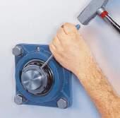
 and with a round piece of wood or pipe, swivel the bearing into position so that the locking device is facing in the same direction as the filling slots ( fig. 3).")
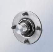
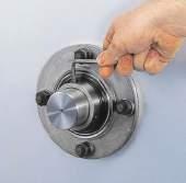
55 washer. Hexagonal head bolts in accordance with ISO 4014:1999 are appropriate. Alternatively, hexagonal socket head cap screws in accordance with ISO 4762:1988 can be used ( fig. 1). Fig. 2 1 Assembling units In cases where the Y-bearing and composite or cast Y-housing are not supplied as a unit, the first step is to assemble the bearing into the housing. To do this, start by removing the locking collar if the bearing has one. Then insert the bearing into the filling slot in the housing bore ( fig. 2) and with a round piece of wood or pipe, swivel the bearing into position so that the locking device is facing in the same direction as the filling slots ( fig. 3). When installing standard bearings, make sure that the relubrication hole in the bearing on the side of the locking device does not coincide with the filling slot in the housing, otherwise grease leakage may result ( fig. 4). When installing stainless steel bearings in KC series housings, make sure that the lubrication groove in the bearing outer ring coincides with the relubrication facility in the housing. Fig. 3 Fig. 4 53
56 Mounting instructions Table 1 Hexagonal keys to tighten grub screws in inner rings or eccentric locking collars sizes and tightening torques SW SW Bearing Bearing or unit Bearing or unit size 1) with metric bore with inch bore Hexagonal Tightening Hexagonal Tightening key size torque key size torque SW SW mm Nm inch Nm Bearing Bearing or unit Bearing or unit size 1) with metric bore with inch bore Hexagonal Tightening Hexagonal Tightening key size torque key size torque SW SW mm Nm inch Nm Bearings in the YAR series, unit with designation suffix TF, TR, TH, THR, NTH, TR/VE495, NTR/VE / / / / /32 6, ,5 5/32 6, ,5 5/32 6, ,5 3/16 16, ,5 3/16 16, ,5 3/16 16, ,5 3/16 16, ,5 7/32 28, ,5 7/32 28, ,5 7/32 28, , , ,5 Bearings in the YAT series, units with designation suffix RM / / / /32 6, /32 6, /32 6, /32 6, ,5 5/32 6,5 11 3/16 16,5 12 3/16 16,5 15 3/16 16,5 16 3/16 16,5 BeBearings in the YET or YEL series, units with designation suffix FM or WF / / / ,5 5/32 6, ,5 3/16 16, ,5 3/16 16, ,5 3/16 16, ,5 3/16 16, ,5 7/32 28, ,5 7/32 28,5 1) For example: bearing size 06 includes all bearings based on a Y 206 bearing, such as YAR F, YAR F, YAR 206-2F, YAR F, YAR F 54
57 Table 2 Hook spanner size and tightening torque for Y-bearings and Y-bearing units on an adapter sleeve 1 Designation Shaft diameter Hook Tightening Y-bearing + adapter sleeve spanner torque d min max mm in Nm Bearings in the YSA series Units with designation suffix KF YSA 205-2FK + HE /4 HN YSA 205-2FK + H HN YSA 206-2FK + HA /16 HN YSA 206-2FK + H HN YSA 206-2FK + HE HN YSA 207-2FK + H HN YSA 207-2FK + HA /16 HN YSA 208-2FK + HE /4 HN YSA 208-2FK + H HN YSA 209-2FK + HA /16 HN YSA 209-2FK + HE /2 HN YSA 209-2FK + H HN YSA 210-2FK + HS /8 HN YSA 210-2FK + HA /16 HN YSA 210-2FK + HE /4 HN YSA 210-2FK + H HN YSA 211-2FK + HA 2311 B 1 15 /16 HN YSA 211-2FK + H HN YSA 211-2FK + HE HN YSA 212-2FK + HS /8 HN YSA 212-2FK + H HN YSA 213-2FK + HA /16 HN YSA 213-2FK + HE /4 HN YSA 213-2FK + H HN YSA 213-2FK + HS /8 HN
58 Mounting instructions Mounting instructions for Y-bearing plummer block units Fig. 1 with a composite or cast housing and grub screws 1 Mount any components that are on the shaft between the two Y-bearing units. 2 Slide the Y-bearing plummer (pillow) block unit onto the shaft with its locking device facing outwards. 3 Position the Y-bearing unit on the support surface. Fit the attachment bolts or nuts but do not tighten them. 4 Mount the other Y-bearing plummer block unit on the other end of the shaft, following steps 2 and 3. 5 Carefully align both Y-bearing units, using the shaft. Fully tighten the attachment bolts or nuts in the housing base. 6 Align the shaft in the bearing arrangement axially and if possible turn it a few times. 7 Tighten the grub screws in the inner rings of both units to the tightening torque indicated in table 1 on page 54 ( fig. 1). 8 If applicable, snap the end cover(s) into place. 56


.")
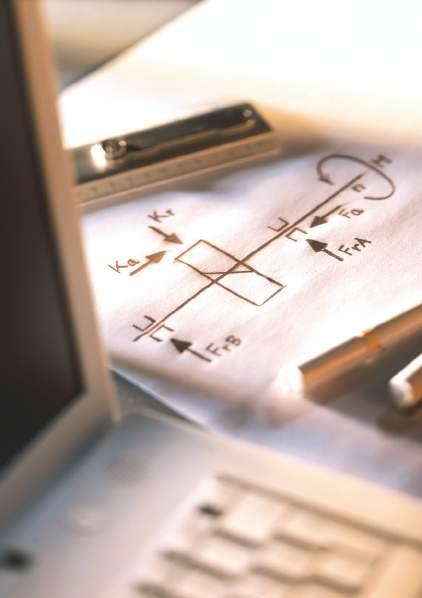
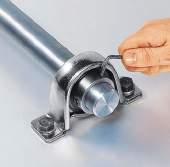
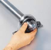
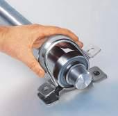
59 Mounting instructions for Y-bearing plummer block units with a cast housing and an eccentric locking collar 1 Mount any components that are on the shaft between the two Y-bearing units. 2 With the eccentric locking collar removed, slide the Y-bearing plummer block unit onto the shaft with the locking device facing outwards. 3 Position the Y-bearing unit on the support surface. Fit the attachment bolts or nuts but do not tighten them. 4 Mount the other Y-bearing plummer block unit on the other end of the shaft, following steps 2 and 3. 5 Carefully align both Y-bearing units, using the shaft. Fully tighten the attachment bolts or nuts in the housing base. 6 Align the shaft in the bearing arrangement axially and if possible turn it a few times. 7 Place the eccentric locking collars on the inner ring extension of both Y-bearing units and snug tighten them in the main direction of rotation ( fig. 1). 8 Tighten the locking collars to their final position, using a hook spanner with a stud engaging the hole in the circumference of the collar ( fig. 2). 9 Tighten the grub screw in the eccentric locking collar of both Y-bearing units ( fig. 3) to the tightening torque indicated in table 1 on page If applicable, snap the end cover(s) into place. Fig. 1 Fig. 2 Fig
60 Mounting instructions Mounting instructions for Y-bearing plummer block units with a cast housing and an adapter sleeve 1 Mount any components that are on the shaft between the two Y-bearing units. 2 Determine the position of the adapter sleeve on the shaft ( fig. 1). 3 Remove the nut and the locking washer from the adapter sleeve ( fig. 2). 4 Wipe the preservative from the bore and outside surface of the sleeve. 5 Expand the adapter sleeve slightly by inserting a screwdriver in the slot of the sleeve and slide the adapter sleeve into position on the shaft ( fig. 3). 6 Slide the Y-bearing plummer block unit up onto the adapter sleeve with the large end of the tapered bore leading, but do not push it. 7 Install the locking washer and screw the lock nut onto the adapter sleeve until the Y-bearing unit is firmly in position on the sleeve. 8 Further tighten the lock nut using one of the following: a hook spanner in the HN series to a tightening angle of about 70 ( fig. 4) a TMHN lock nut spanner to a tightening angle of about 70 a torque wrench to the tightening torque indicated in table 2 on page 55 Make sure that while tightening the nut, the sleeve does not rotate on the shaft. 9 Lock the nut in position by bending down a tab on the locking washer in one of the slots provided around the circumference of the nut ( fig. 5). 10 Mount the other Y-bearing plummer block unit on the other end of the shaft, following steps 2 through Position the Y-bearing units on their support surfaces. Fit the attachment bolts or nuts but do not tighten them. 12 Carefully align both Y-bearing units, using the shaft and, if possible, turn it a few times. Then tighten the attachment bolts or nuts. 13 If applicable, snap the end cover(s) into place. 58


61 Fig. 1 Fig. 2 1 Fig. 3 Fig. 4 Fig. 5 59
62 Mounting instructions Mounting instructions for Y-bearing plummer block units with a pressed steel housing and grub screws 1 Mount any components that are on the shaft between the two Y-bearing units. 2 Slide the Y-bearings with the locking device facing outward onto the shaft at both ends. Install the rubber seating ring on the outside diameter of the bearing (optional). 3 Place the base of each housing on its support surface. 4 Place the shaft and Y-bearings into position in each housing base. Then, place the housing caps over the bearings ( fig. 1) and install the attachment bolts or nuts. 5 Carefully align both Y-bearing units, using the shaft. Then, tighten the attachment bolts or nuts. 6 Align the shaft in the bearing arrangement axially and if possible turn it a few times. 7 Tighten the grub screws in the inner ring of both bearings ( fig. 2) to the tightening torque indicated in table 1 on page

63 Fig. 1 1 Fig. 2 61
64 Mounting instructions Mounting instructions for Y-bearing plummer block units with a pressed steel housing and an eccentric locking collar 1 Mount any components that are on the shaft between the two Y-bearing units. 2 With the eccentric locking collar removed, slide the Y-bearings onto both shaft ends with the locking device facing outwards. Install the rubber seating ring on the outside diameter of the bearing (optional). 3 Place the base of each housing on its support surface. 4 Place the shaft and Y-bearings into position in each housing base. Then, place the housing caps over the bearings ( fig. 1) and install the attachment bolts or nuts. 5 Carefully align both Y-bearing units, using the shaft. Then, tighten the attachment bolts or nuts. 6 Align the shaft in the bearing arrangement axially and if possible turn it a few times. 7 Place the eccentric locking collars on the inner ring extension of both Y-bearings and snug tighten them in the main direction of rotation ( fig. 2). 8 Tighten the locking collars to their final position, using a hook spanner with a stud engaging the hole in the circumference of the collar ( fig. 3). 9 Tighten the grub screw in the eccentric locking collar of both Y-bearings ( fig. 4) to the tightening torque indicated in table 1 on page


65 Fig. 1 Fig. 2 1 Fig. 3 Fig. 4 63
66 Mounting instructions Mounting instructions for flanged Y-bearing units Fig. 1 with a composite (Y-TECH) or cast housing and grub screws 1 Mount any components that are on the shaft between the two Y-bearing units. 2 Slide the flanged Y-bearing unit onto the shaft. 3 Fasten the Y-bearing unit securely to the machine wall. 4 Mount the other flanged Y-bearing unit to the opposite end of the shaft, following steps 2 and 3 5 Align the shaft in the bearing arrangement axially and if possible turn it a few times. 6 Tighten the grub screws on the inner ring of both units ( fig. 1) to the tightening torque indicated in table 1 on page If applicable, snap the end cover(s) into place. 64

67 Mounting instructions for flanged Y-bearing units with a composite (Y-TECH) or cast housing and an eccentric locking collar 1 Mount any components that are on the shaft between the two Y-bearing units. 2 With the eccentric locking collar removed, slide the flanged Y-bearing unit onto the shaft with the locking device facing outwards. 3 Fasten the Y-bearing unit securely to the machine wall. 4 Mount the other flanged Y-bearing unit to the opposite end of the shaft, following steps 2 and 3. 5 Align the shaft in the bearing arrangement axially and if possible turn it a few times. 6 Place the eccentric locking collars on the inner ring of both Y-bearings and snug tighten them in the main direction of rotation ( fig. 1). 7 Tighten the locking collars to their final position using a hook spanner with a stud engaging the hole in the circumference of the collar ( fig. 2). 8 Tighten the grub screw in the eccentric locking collar of both units ( fig. 3) to the tightening torque indicated in table 1 on page If applicable, snap the end cover(s) into place. Fig. 1 Fig. 2 1 Fig. 3 65
68 Mounting instructions Mounting instructions for flanged Y-bearing units with a cast housing and an adapter sleeve 1 Mount any components that are on the shaft between the two Y-bearing units. 2 Determine the position of the adapter sleeve on the shaft ( fig. 1). Take into consideration that later during mounting the Y-bearing unit will move axially on the sleeve or vice versa the shaft will move axially against the Y-bearing unit. This is particularly important when mounting the second Y-bearing unit. 3 Remove the nut and locking washer from the adapter sleeve ( fig. 2). 4 Wipe the preservative from the bore and outside surface. 5 Expand the adapter sleeve slightly by inserting a screwdriver in the slot of the sleeve and slide the adapter sleeve into position on the shaft ( fig. 3). 6 Slide the Y-bearing unit up onto the adapter sleeve with the large end of the tapered bore leading, but do not push it. 7 Fasten the Y-bearing unit securely to the machine wall. 8 Install the locking washer and screw the lock nut onto the adapter sleeve until the Y-bearing unit is firmly in position on the sleeve. 9 Further tighten the lock nut using one of the following: a hook spanner in the HN series to a tightening angle of about 70 ( fig. 4) a TMHN lock nut spanner to a tightening angle of about 70 a torque wrench to the tightening torque indicated in table 2 on page 55 Make sure that while tightening the nut, the sleeve does not rotate on the shaft. 10 Lock the nut in position by bending down a tab on the locking washer into one of the slots provided around the circumference of the nut ( fig. 5). 11 Mount the second Y-bearing unit at the other end of the shaft, following steps 2 through Make sure the shaft turns smoothly and the bearings are not jammed in place. If necessary, remove the last Y-bearing unit to be mounted, determine a new installation position for the adapter sleeve on the shaft and mount the Y-bearing unit again. 13 If the shaft turns smoothly, secure the Y-bearing unit on the adapter sleeve by bending down a tab on the locking washer into one of the slots provided around the circumference of the nut ( fig. 5). 14 If applicable, snap the end cover(s) into place. 66


69 Fig. 1 Fig. 2 1 Fig. 3 Fig. 4 Fig. 5 67
70 Mounting instructions Mounting instructions for flanged Y-bearing units with a pressed steel housing and grub screws 1 Mount any components that are on the shaft between the two Y-bearing units. 2 Place one housing half into position on the machine wall with threaded fasteners ( fig. 1). 3 With the locking device facing outward, slide the Y-bearing onto the shaft and into the housing half. 4 Place the second housing half into position over the Y-bearing ( fig. 2). 5 Fit the threaded fasteners (nuts or bolts), but do not tighten them. 6 Mount the Y-bearing unit at the other end of the shaft, following steps 2 through 5. 7 Tighten the threaded fasteners holding the flanged units in place. 8 Align the shaft in the bearing arrangement axially and if possible turn it a few times. 9 Tighten the grub screws on both units ( fig. 3) to the tightening torque indicated in table 1 on page

71 Fig. 1 1 Fig. 2 Fig. 3 69
72 Mounting instructions Mounting instructions for flanged Y-bearing units with a pressed steel housing and an eccentric locking collar 1 Mount any components that are on the shaft between the two Y-bearing units. 2 Place one housing half into position on the machine wall with threaded fasteners ( fig. 1). 3 With the eccentric locking collar removed, slide the Y-bearing onto the shaft and into the housing half with the locking device facing outwards. 4 Place the second housing half into position over the Y-bearing ( fig. 2). 5 Fit the threaded fasteners (nuts or bolts), but do not tighten them. 6 Mount the other Y-bearing unit at the other end of the shaft, following steps 2 through 5. 7 Tighten the threaded fasteners holding the flanged units in place. 8 Align the shaft in the bearing arrangement axially and if possible turn it a few times. 9 Place the eccentric locking collars on the inner ring extension of both Y-bearings and snug tighten them in the main direction of rotation ( fig. 3). 10 Tighten the locking collars to their final position using a hook spanner with a stud engaging the hole in the circumference of the collar ( fig. 4). 11 Tighten the grub screw in the eccentric locking collar of both units ( fig. 5) to the tightening torque indicated in table 1 on page

73 Fig. 1 Fig. 2 1 Fig. 3 Fig. 4 Fig. 5 71
74 Mounting instructions Mounting instructions for Y-bearing take-up units with a cast housing and grub screws 1 Mount any components that are on the shaft between the two Y-bearing units. 2 Slide the Y-bearing take-up units onto both shaft ends with the locking device facing outward. 3 Install the shaft and Y-bearing take-up units into the take-up frames and connect the adjustment screws via the cast hole in the units. 4 Align the shaft in the bearing arrangement axially and if possible turn it a few times. 5 Tighten the grub screws on both Y-bearing take-up units to the tightening torque indicated in table 1 on page If applicable, snap the end cover(s) into place. 72
75 Mounting instructions for Y-bearing take-up units 1 with a cast housing and an eccentric locking collar 1 Mount any components that are on the shaft between the two Y-bearing units. 2 With the eccentric locking collar removed, slide the Y-bearing take-up units onto both shaft ends with the locking device facing outwards. 3 Install the shaft with the Y-bearing take-up units into the take-up frames and connect the adjustment screws via the cast hole in the units. 4 Align the shaft in the bearing arrangement axially and if possible turn it a few times. 5 Place the eccentric locking collars on the inner ring extension of both Y-bearing units and snug tighten them in the main direction of rotation. 6 Tighten the locking collars to their final position using a hook spanner with a stud engaging the hole in the circumference of the collar. 7 Tighten the grub screw in the eccentric locking collar of both Y-bearing units to the tightening torque indicated in table 1 on page If applicable, snap the end cover(s) into place. 73

76 Storing Y-bearings and Y-bearing units Y-bearings and Y-bearing units are normally treated with a rust preventive compound and can be stored in their original unopened package for a number of years. However, they should be kept in a vibration-free, dry environment where the relative humidity does not exceed 60% and the temperature is reasonably constant. When Y-bearings and Y-bearing units are stored for long periods, they may have a higher initial starting torque than Y-bearings or units recently delivered from the factory. Also, the lubricating properties of the grease may have deteriorated after long periods of storage. Y-bearings and Y-bearing units, which are no longer in their original packages, must be adequately protected against corrosion and con tamination and should also be identified in some way by their complete designation. 74

77 Designation systems 1 The complete designation for a Y-bearing or a Y-bearing unit consists of: prefixes, identifying the Y-bearing or Y-bearing unit series figures, identifying the size suffixes, identifying designs and variants More details about the basic designations and the supplementary designations can be obtained from the designation charts: Y-bearing designation system ( table 1, page 76) Y-bearing unit designation system ( table 2, page 77) 75
78 Designation systems Table 1 Y-bearing designation system Examples YAR 208-2RF/HV YEL 203/15-2FW YAR RF/HV YEL 2 03/15 2FW Bearing series YAR Inner ring extended on both sides, with grub screws YAT Inner ring extended on one side, with grub screws YEL Inner ring extended on both sides, with an eccentric locking collar YET Inner ring extended on one side, with an eccentric locking collar YHB Inner ring extended on both sides, hexagonal bore YHC Inner ring extended on both sides, hexagonal bore YQC Inner ring extended on both sides, square bore YSA Inner ring symmetrically extended on both sides Dimension series 2 Bearing to ISO 9628: Bearing to ISO 15:1998, Dimension Series 02, sphered outside diameter Bearing to ISO 15:1998, Dimension Series 03, sphered outside diameter Bore diameter Bearings for metric shafts 03/12 12 mm bore diameter 03/15 15 mm bore diameter mm bore diameter mm bore diameter to mm bore diameter Bearings for inch shafts Three-figure combination that follows the designation of the basic metric bearing and is separated from this by a hyphen; the first figure is the number of whole inches and the second and third figures are the number of sixteenths of an inch, e.g /4 in = 19,050 mm bore diameter in = 25,400 mm bore diameter to /2 in = 63,500 mm bore diameter Suffixes Seals Contact standard integral seal on both sides of the bearing 2F Contact standard integral seal with an additional plain flinger on both sides of the bearing 2LS8 Contact seal of synthetic rubber with sheet steel reinforcement on both sides of the bearing 2RF Contact standard integral seal with an additional rubberized flinger on both sides of the bearing 2RS1 Contact seal of synthetic rubber with sheet steel reinforcement on both sides of the bearing VP076 Pressed sheet steel shield on both sides of the bearing Material HV Bearing components of stainless steel and food-grade grease VA201 Bearing with pressed steel cage for high temperatures VA228 Bearing with coronet cage of graphite for temperatures 150 to +350 C VE495 Zinc-coated inner and outer ring and stainless steel flingers, food-grade grease VL065 Zinc-coated inner ring bore and side faces Other features AH Bearing for air-handling applications C Cylindrical outside diameter G Lubrication groove in the outside diameter, located at the side opposite the locking device GR Lubrication groove in the outside diameter, located at the side of the locking device K Tapered bore, taper 1:12 U Bearing without an eccentric locking collar VT357 Bearing filled with a special grease W Bearing without lubrication hole(s) W64 Solid Oil fill 76
79 Table 2 Y-bearing unit designation system Examples FYTBKC 30 NTR/VE495 SY 1.1/2 TF TUJ 50 TF PFD 40 FY TB KC 30 NTR /VE495 SY 1.1/2 TF TUJ 50 TF PF D 40 1 Identification of housing type J stands for dimensions to standard JIS FY(J) Flanged housing P Plummer block housing, pressed steel PF Flanged housing, pressed steel SY(J) Plummer block housing TU(J) Take-up housing Identification of unit design Base version; when flanged: square flange C Flanged unit, round flange D Flanged unit, triangular flange F Plummer block unit, short base H Plummer block unit, lower centre height M Plummer block unit, higher load carrying capacity T Flanged unit, oval flange TB Flanged unit, oval flange TF Flanged unit, oval flange, no relubrication facility Identification of housing material Grey cast iron K Composite material, black coloured, with zinc-coated sheet steel inserts KC Composite material, light-grey coloured, with stainless steel inserts and embedded steel coil L Composite material, light-grey coloured, with stainless steel inserts Identification of size Bearing units for metric shafts: in millimetres uncoded mm bore diameter to mm bore diameter Bearing units for inch shafts: in inches uncoded 3/4 3/4 in = 19,05 mm bore diameter to 2 1/2 2 1 /2 in = 63,5 mm bore diameter Housings from grey cast iron or composite material 503 for Y-bearings of sizes 203, 203/12 and 203/15 to 520 for Y-bearings of size 220 Housings from sheet steel (not supplied as bearing unit) mm housing bore diameter to mm housing bore diameter Identification of inserted Y-bearing FM Y-bearing with an eccentric locking collar, YET 2 series KF Y-bearing with a tapered bore, YSA 2-2FK series NTH Y-bearing with grub screws, YAR-2RF/HV series NTR Y-bearing with grub screws, YAR-2RF/VE495 series PF Y-bearing with SKF ConCentra locking RM Y-bearing with grub screws, YAT 2 series TF Y-bearing with grub screws, YAR 2-2F series TR Y-bearing with grub screws, YAR 2-2RF series WF Y-bearing with an eccentric locking collar, YEL 2-2F series Other features See table 1 Y-bearing designation system 77
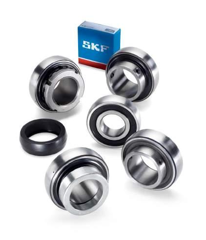
80 78
81 Y-bearings Designs Special designs Y-bearings with grub screws Bearings made of rolling bearing steel Bearings with zinc-coated rings Stainless steel bearings Y-bearings with an eccentric locking collar Y-bearings with a tapered bore Y-bearings with a standard inner ring Y-bearings with a hexagonal or square bore Seals Standard seals Standard seals with an additional flinger Multiple seals RS1 seals LS8 seals Shields Permissible operating temperatures for seals Data general Dimensions Tolerances Radial internal clearance Cages Grease fills Mounting Product tables Y-bearings with grub screws, metric shafts inch shafts Y-bearings with an eccentric locking collar, metric shafts inch shafts Y-bearings with a tapered bore on an adapter sleeve, metric shafts inch shafts Y-bearings with a standard inner ring, metric shafts Y-bearings with a hexagonal bore, inch shafts
82 Y-bearings Designs Fig. 2 SKF Y-bearings, which are usually referred to as insert bearings, are basically sealed deep groove ball bearings in the 62 and 63 series, with a convex outer ring. These bearings are manufactured in a number of different series and sizes and are available with a standard inner ring or an inner ring that is extended on one or both sides ( fig. 1). The various insert bearing series differ in the way the bearing is located onto the shaft. The most common methods use any one of the following: grub (set) screws ( fig. 2) eccentric locking collar ( fig. 3) adapter sleeve ( fig. 4) interference fit ( fig. 5) Fig. 3 The standard SKF assortment includes Y-bearings made of rolling bearing steel as well as stainless steel and Y-bearings with zinc-coated components. Fig. 1 Fig. 4 80
83 Special designs In addition to the standard range, the following special insert bearings are available: Y-bearings for extreme temperature applications ( page 249) Y-bearings for the food industry ( page 274) Y-bearings with Solid Oil ( SKF Interactive Engineering Catalogue, available online at 2 Other variants include Y-bearings with: special coatings non-contacting seals special grease fills These special bearings are designed for applications where operating temperatures may exceed the range for standard bearings, where conventional lubrication methods or materials can not be used, or where smooth running is a key operational parameter. Fig. 5 81
84 Y-bearings Y-bearings with grub screws Y-bearings with grub screws in the inner ring are locked in position on the shaft by tightening the two cup point hexagonal grub screws, positioned 120 apart. These bearings are suitable for applications where the direction of rotation is constant or alternating. Two different standard designs are available. Y-bearings in the YAT 2 series have an extended inner ring on one side, and are sealed with the rugged standard integral seal ( fig. 6). The outer ring has two lubrication holes as standard. Y-bearings in the YAR 2 series have an extended inner ring on both sides ( fig. 7). This reduces the extent to which the inner ring can tilt on the shaft, which enables the bearing to run more smoothly. These bearings are fitted with the rugged standard integral seal and one of the following flinger options: Fig. 6 Fig. 7 plain sheet steel flingers, designation suffix 2F rubberized sheet steel flingers (multiple seal), designation suffix 2RF The outer ring has two lubrication holes as standard. Bearings without lubrication holes can be supplied on request. They are identified by the suffix W. Bearings made of rolling bearing steel Y-bearings in the YAT 2 and YAR 2 standard series are manufactured from high-grade carbon chromium steel. The SKF range comprises bearings for metric shafts from 12 to 100 mm and inch shafts from 1 /2 to 3 inch ( product table on pages 92 to 97). 82
85 Bearings with zinc-coated rings Y-bearings with an extended inner ring on both sides (YAR 2 series) are also available with zinccoated rings for use in corrosive environments. These bearings, series designation YAR 2-2RF/VE495: use highly efficient multiple seals made of food-compatible rubber and stainless steel flingers are fitted with grub screws made of stainless steel are filled with a food-grade grease can be relubricated through the lubrication holes in the outer ring 2 The SKF range of Y-bearings with zinc-coated rings covers bearings for metric shafts from 20 to 40 mm ( product table on page 92). Stainless steel bearings All steel components of stainless steel Y-bearings are made of stainless steel. This includes the rings, balls, sheet metal parts of the seal and the grub screws. The inner ring is extended on both sides. These bearings, series designation YAR 2-2RF/HV: use highly efficient multiple seals made of food-compatible rubber are filled with a food-grade grease can be relubricated through one lubrication hole in the outer ring The SKF range covers bearings for metric shafts from 20 to 40 mm as well as inch shafts from 3/4 to 1 1 /2 inch ( product table on page 92 to 96). The dynamic load carrying capacity of a stainless steel bearing is less than that of a similarly sized standard steel bearing. 83
86 Y-bearings Y-bearings with an eccentric locking collar Y-bearings with an eccentric locking collar are intended primarily for use in applications where the direction of rotation is constant. On one side of the bearing inner ring is an eccentric extension that fits the locking collar. Turning the locking collar on the inner ring extension in the direction of rotation locks the collar and bearing on the shaft. A single grub screw further secures the collar to the shaft. There are two standard series available from SKF. Y-bearings in the YET 2 series have an extended inner ring on one side and are fitted with the rugged standard integral seal ( fig. 8). The eccentric collar is coated (zinc-coated for bearings with a metric bore, black oxidized for bearings with an inch bore). The outer ring has two lubrication holes as standard. Y-bearings in the YEL 2 series have an extended inner ring on both sides ( fig. 9). This reduces the extent to which the inner ring can tilt on the shaft, which enables the bearing to run more smoothly. These bearings are fitted with the rugged standard integral seal and one of the following flinger options: Fig. 8 Fig. 9 plain sheet steel flingers, designation suffix 2F rubberized sheet steel flingers (multiple seal), designation suffix 2RF/VL065 The outer ring has two lubrication holes as standard. Bearings without lubrication holes can be supplied on request. They are identified by the suffix W. The SKF range comprises bearings for metric shafts from 15 to 60 mm and inch shafts from 1/2 to 2 7 /16 inch ( product table on pages 98 to 101). 84
87 Fig. 10 Fig. 11 Y-bearings with a tapered bore Y-bearings in the YSA 2-2FK series ( fig. 10) have a symmetrically extended inner ring on both sides and a tapered bore (taper 1:12) enabling them to be mounted on a standard adapter sleeve in the H 23 series. The appropriate adapter sleeve is not part of the bearing and must be ordered separately. Y-bearings with a tapered bore are equipped with the rugged standard integral seal, fitted with additional plain sheet steel flingers. The outer ring has two lubrication holes as standard. Mounting onto an adapter sleeve enables the bearings to operate at higher speeds and run more smoothly in applications where the direction of rotation is constant or alternating. The SKF range, which comprises bearings with bore diameters ranging from 25 to 65 mm, fits adapter sleeves in the H 23 series for metric shafts ranging from 20 to 60 mm ( product table on page 102). These bearings can also be used on adapter sleeves in the HA 23, HE 23 and HS 23 series for inch shafts ranging from 3/4 to 2 3 /8 inch ( product table on page 104). Y-bearings with a standard inner ring Y-bearings in the 17262(00)-2RS1 and 17263(00)-2RS1 series ( fig. 11) with a standard inner ring have normal tolerances for the bearing bore diameter and are located on the shaft using an appropriate interference fit. They do not have any lubrication holes in the outer ring. The only difference between these Y-bearings and deep groove ball bearings in the 62 and 63 series is the sphered outside surface of the outer ring. These Y-bearings are suitable for applications where the direction of the load alternates and where smooth running is a key operational parameter. These bearings can accommodate heavier axial loads than Y-bearings of any other design. They can also operate at the same speeds as the corresponding sealed deep groove ball bearings. The SKF range comprises bearings for metric shafts from 17 to 60 mm ( product table on page 106). 2 85
88 Y-bearings with a hexagonal or square bore Y-bearings with a hexagonal or square bore are intended primarily for high torque applications. The bore is produced to a plus tolerance and enables easy mounting and dismounting. These bearings should be axially located on the shaft using adjacent components. The bearings have a standard outer ring without lubrication holes (designation suffix W). Bearings in the YHB 2 and YHC 2 series have a hexagonal bore ( fig. 12). They are equipped with rugged contact seals (designation suffix LS8). The SKF assortment comprises bearings for shafts with width flats from 1 1 /8 to 1 1 /2 inch across ( product table on page 108). For more information, contact the SKF application engineering service. Fig
89 Fig. 13 Fig. 14 Seals Since Y-bearings were originally developed for use in agricultural applications, sealing has always been very important. Therefore, SKF Y-bearings are available with different sealing configurations to suit the operating conditions. Standard seals The standard seal for SKF Y-bearings is the rugged integral seal. It consists of a pressed sheet steel washer with a sealing lip made of acrylo nitrile-butadiene rubber (NBR) vulcanized to its inner surface ( fig. 13). The non-contact sheet steel washer forms a narrow gap with the cylindrical surface of the inner ring shoulder and protects the land-riding seal against coarse contaminants. 2 Standard seals with an additional flinger For more contaminated environments, a Y-bearing with an inner ring extended on both sides should be used. These bearings are equipped with seals that have an additional plain, sheet steel flinger on the outboard side of the integral standard seal ( fig. 14) and are identified by the designation suffix 2F. The flingers are made of sheet steel or stainless sheet steel respectively, have an interference fit on the inner ring and considerably enhance the seals effectiveness without increasing friction. Fig. 15 Multiple seals For Y-bearing arrangements requiring a high degree of reliability, even in extremely contaminated environments, a bearing with an inner ring extended on both sides should be used with the highly efficient multiple seal arrangement. In this sealing arrangement ( fig. 15), a flinger with a vulcanized rubber lip is fitted outside the standard integral seal. This acrylo nitrilebutadiene rubber lip seals axially against the integral seal. The space between the integral seal and the rubberized flinger is filled with grease to provide additional protection. 87
90 Y-bearings RS1 seals Y-bearings with a standard inner ring, 17262(00)- 2RS1 and 17263(00)-2RS1 series, are equipped with the RS1 contact seal developed for standard SKF deep groove ball bearings ( fig. 16). These seals, which are made from oil and wear resistant acrylonitrile-butadiene rubber (NBR), are reinforced with a pressed sheet steel insert and seal against the cylindrical surface of the inner ring shoulder. Fig. 16 LS8 seals Y-bearings with a hexagonal bore, series YHB 2 and YHC 2, are equipped with LS8 contact seals ( fig. 17). These seals, which are made from acrylonitrile-butadiene rubber (NBR), are reinforced with a pressed sheet steel insert and seal against the cylindrical surface of the inner ring shoulder. Fig. 17 Shields Y-bearings are also available with shields ( fig. 18), which are identified by the designation suffix VP076. Pressed steel shields are used in temper ature or speed sensitive applications where additional friction is not desirable. In applications where shielded bearings are used, contamination should not be severe and water, steam or moisture should not be able to enter the bearing. Permissible operating temperatures for seals Contact seals can be used at operating temperatures between 30 and +100 C. Temperatures up to 120 C are also possible for brief periods, but might have a negative effect on the service life of the grease. Fig
91 Data general Dimensions The boundary dimensions of Y-bearings in the YAR 2, YET 2 and YEL 2 series are in accordance with ISO 9628:2006. The boundary dimensions of Y-bearings in the 17262(00)-2RS1 and 17263(00)-2RS1 series are in accordance with those of deep groove ball bearings in the 62 and 63 series and are in accordance with ISO 15:1998, except that the bearings have a sphered outside diameter The boundary dimensions of Y-bearings in the YSA 2-2FK series are in accordance with JIS Y-bearings in the YAT 2, YHB 2, YHC 2 and YQC 2 series have not been standardized either nationally or internationally, but are common in the marketplace. The dimensions of the adapter sleeves in the H 23 series, which are normally used to locate YSA 2-2FK bearings onto the shaft, are in accordance with ISO :1995. Tolerances The bore and outside diameter of Y-bearings are produced to tolerances indicated in table 1. Symbols used are explained in the following. The values specified for the tolerance zone of the bore diameter of bearings in the YAT 2, YAR 2, YET 2 and YEL 2 series are slightly tighter than Normal tolerances listed in ISO 9628:2006. The values specified for bearings in the 17262(00)-2RS1 and 17263(00)-2RS1 series are in accordance with ISO 492:2002. SKF manufactures bearings in the YSA 2-2FK series with a tapered bore, taper 1:12. They are designed to fit adapter sleeves in the H 23 series, for metric and inch shafts. The hexagonal or square bore of bearings in the YHB 2, YHC 2 and YQC 2 series is produced to a 0/+0,25 mm tolerance. Symbols d Nominal bore diameter D dmp Deviation of the mean bore diameter from the nominal D Nominal outside diameter D Dmp Deviation of the mean outside diameter from the nominal 2 Tolerances for SKF Y-bearings Table 1 Nominal Inner ring Outer ring diameter Bearings in the series All bearings YAT 2, YAR 2, 17262(00) YET 2, YEL (00) d, D D dmp D dmp D Dmp Over Incl. High Low High Low High Low mm μm μm μm , ,75 50, ,8 80, ,
92 Y-bearings Radial internal clearance Y-bearings are manufactured as standard with the radial internal clearance indicated in table 2. The values specified there for bearings in the: YAT, YAR, YET, YEL, YHB, YHC and YQC series are in accordance with Group N radial internal clearances as listed ISO 9628:2006 YSA 2 K series are in accordance with Group 3 radial internal clearances as listed in ISO 9628: (00)-2RS1 and 17263(00)-2RS1 series are manufactured with Normal radial internal clearances for deep groove ball bearings as standard. The values are in accordance with ISO 5753:1991 Table 2 Radial internal clearance for Y-bearings Bearing size 1) Radial internal clearance of Y-bearings in the series YAT 2, YAR 2, YSA 2 K (00) YET 2, YEL (00) YHC 2 from to min max min max min max μm ) For example: bearing size 06 includes all bearings based on a Y 206 bearing, such as YAR F, YAR F, YAR 206-2F, YAR F, YAR F 90
93 Cages All standard Y-bearings are fitted with an injection moulded snap-type cage of glass fibre reinforced polyamide 66 ( fig. 19). These cages exhibit excellent performance characteristics in a variety of applications where operating temperatures do not exceed 120 C. The lubricants generally used for Y-bearings do not have any detrimental effect on cage properties. Fig Grease fills All standard design SKF Y-bearings and Y-bearings with a square bore are filled with a high quality, long lasting grease containing a lithium-calcium thickener with a consistency of 2 on the NLGI scale. Y-bearings made of stainless steel, in the YAR 2-2RF/HV series, and Y-bearings with zinccoated rings, in the YAR 2-2RF/VE495 series, meet the demands of food-processing machinery in a corrosive environment. They are filled with a non-toxic, food-grade grease based on a synthetic hydrocarbon oil using an aluminiumcomplex soap as a thickener. Y-bearings with a hexagonal bore are filled with a premium quality, mineral oil based grease using a lithium-complex soap (designation suffix VT357). The grease, which has a consistency of 3 on the NGLI scale, has good water and corrosion resistant properties and provides excellent lubrication at high operating temperatures. For additional information about lubrication and different lubricants, refer to the section Lubrication and maintenance, starting on page 48. Mounting The mounting procedures for Y-bearings depend on the method used to attach the unit to the shaft. The procedures are described in detail in the section Mounting instructions, starting on page 52. Y-bearings with a standard inner ring are mounted on the shaft with an interference fit. 91
94 Y-bearings with grub screws, metric shafts d mm C D B r 1 r 2 d d 1 B s 1 s 1 YAT YAR-2F YAR-2RF Dimensions Basic load ratings Fatigue Limiting Mass Designation dynamic static load speed limit with shaft d D B C d 1 s 1 r 1,2 C C 0 P u tolerance min h6 mm kn kn r/min kg , ,2 15,9 0,3 9,56 4,75 0, ,11 YAR 203/12-2F , ,2 15,9 0,3 9,56 4,75 0, ,10 YAR 203/15-2F , ,2 15,9 0,3 9,56 4,75 0, ,07 YAT , ,2 15,9 0,3 9,56 4,75 0, ,09 YAR 203-2F , ,2 18,3 0,6 12,7 6,55 0, ,11 YAT ,2 18,3 0,6 12,7 6,55 0, ,14 YAR 204-2F ,2 18,3 0,6 12,7 6,55 0, ,14 YAR 204-2RF ,2 18,3 0,6 10,8 6,55 0, ,14 YAR 204-2RF/HV ,2 18,3 0,6 12,7 6,55 0, ,14 YAR 204-2RF/VE , ,7 19,5 0,6 14 7,8 0, ,14 YAT , ,7 19,8 0,6 14 7,8 0, ,17 YAR 205-2F 52 34, ,7 19,8 0,6 14 7,8 0, ,17 YAR 205-2RF 52 34, ,7 19,8 0,6 11,9 7,8 0, ,18 YAR 205-2RF/HV 52 34, ,7 19,8 0,6 14 7,8 0, ,18 YAR 205-2RF/VE , ,7 21 0,6 19,5 11,2 0, ,23 YAT , ,7 22,2 0,6 19,5 11,2 0, ,28 YAR 206-2F 62 38, ,7 22,2 0,6 19,5 11,2 0, ,28 YAR 206-2RF 62 38, ,7 22,2 0,6 16,3 11,2 0, ,29 YAR 206-2RF/HV 62 38, ,7 22,2 0,6 19,5 11,2 0, ,29 YAR 206-2RF/VE ,1 23,3 1 25,5 15,3 0, ,31 YAT , ,1 25,4 1 25,5 15,3 0, ,41 YAR 207-2F 72 42, ,1 25,4 1 25,5 15,3 0, ,41 YAR 207-2RF 72 42, ,1 25,4 1 21,6 15,3 0, ,42 YAR 207-2RF/HV 72 42, ,1 25,4 1 25,5 15,3 0, ,42 YAR 207-2RF/VE ,8 25,3 1 30,7 19 0, ,43 YAT , ,8 30,2 1 30,7 19 0, ,55 YAR 208-2F 80 49, ,8 30,2 1 30,7 19 0, ,55 YAR 208-2RF 80 49, ,8 30,2 1 24,7 19 0, ,56 YAR 208-2RF/HV 80 49, ,8 30,2 1 30,7 19 0, ,56 YAR 208-2RF/VE ,8 25,8 1 33,2 21,6 0, ,48 YAT , ,8 30,2 1 33,2 21,6 0, ,60 YAR 209-2F 85 49, ,8 30,2 1 33,2 21,6 0, ,60 YAR 209-2RF 92
95 2.1 Dimensions Basic load ratings Fatigue Limiting Mass Designation dynamic static load speed limit with shaft d D B C d 1 s 1 r 1,2 C C 0 P u tolerance min h6 mm kn kn r/min kg , ,5 27,6 1 35,1 23,2 0, ,54 YAT , ,5 32,6 1 35,1 23,2 0, ,69 YAR 210-2F 90 51, ,5 32,6 1 35,1 23,2 0, ,69 YAR 210-2RF , ,1 33,4 1 43,6 29 1, ,94 YAR 211-2F , ,1 33,4 1 43,6 29 1, ,94 YAR 211-2RF , ,6 39,7 1,5 52,7 36 1, ,30 YAR 212-2F , ,6 39,7 1,5 52,7 36 1, ,30 YAR 212-2RF , ,5 42,9 1,5 57,2 40 1, ,70 YAR 213-2F , ,5 42,9 1,5 57,2 40 1, ,70 YAR 213-2RF , ,7 1,5 62,4 45 1, ,85 YAR 214-2F , ,1 1,5 66,3 49 2, ,05 YAR 215-2F , ,4 47,7 2 72,8 53 2, ,45 YAR 216-2F ,8 2 83,2 62 2, ,20 YAR 217-2F , ,6 72 2, ,00 YAR 218-2F , ,5 63, , ,25 YAR 220-2F 93
96 Y-bearings with grub screws, inch shafts d 1 /2 1 7 /16 in C D B r 1 r 2 d d 1 B s 1 s 1 YAT YAR-2F YAR-2RF Dimensions Basic load Fatigue Limiting Mass Designation ratings load speed dynamic static limit with shaft d D B C d 1 s 1 r 1,2 C C 0 P u tolerance min h6 in/mm lbf/kn lbf/kn r/min lb/kg 1/ YAR F 12, , ,2 15,9 0,3 9,56 4,75 0,2 0,12 5/ YAR F 15, , ,2 15,9 0,3 9,56 4,75 0,2 0, YAT , ,2 16 0,3 9,56 4,75 0,2 0,10 3/ YAR F 19, ,2 18,3 0,6 12,7 6,55 0,28 0, YAR RF ,2 18,3 0,6 12,7 6,55 0,28 0, YAR F/AH ,2 18,3 0,6 12,7 6,55 0,28 0, YAR RF/HV ,2 18,3 0,6 10,8 6,55 0,28 0, YAT , ,2 18,3 0,6 12,7 6,55 0,28 0,14 7/ YAT , , ,7 19,5 0,6 14 7,8 0,335 0,17 15/ YAR F 23, , ,7 19,8 0,6 14 7,8 0,335 0, YAT , ,7 19,5 0,6 14 7,8 0,335 0, YAR F 25, , ,7 19,8 0,6 14 7,8 0,335 0, YAR RF 52 34, ,7 19,8 0,6 14 7,8 0,335 0, YAR F/AH 52 34, ,7 19,8 0,6 14 7,8 0,335 0, YAR RF/HV 52 34, ,7 19,8 0,6 11,9 7,8 0,335 0, YAT , ,7 19,5 0,6 14 7,8 0,335 0, / YAR F 26, , ,7 22,2 0,6 19,5 11,2 0,475 0,34 94
97 2.1 Dimensions Basic load Fatigue Limiting Mass Designation ratings load speed dynamic static limit with shaft d D B C d 1 s 1 r 1,2 C C 0 P u tolerance min h6 in/mm lbf/kn lbf/kn r/min lb/kg 1 1 / YAR F 28, , ,7 22,2 0,6 19,5 11,2 0,475 0, / YAR F 30, , ,7 22,2 0,6 19,5 11,2 0,475 0, YAR F/AH 62 38, ,7 22,2 0,6 19,5 11,2 0,475 0, YAT , ,5 11,2 0,475 0, YAR RF/HV 62 38, ,7 22,2 0,6 16,3 11,2 0,475 0, / YAR F 31, , ,7 22,2 0,6 19,5 11,2 0,475 0, YAR F 72 42, ,1 25,4 1 25,5 15,3 0,655 0, YAR RF 72 42, ,1 25,4 1 25,5 15,3 0,655 0, YAR RF/HV 72 42, ,1 25,4 1 21,6 15,3 0,655 0, YAT , ,5 11,2 0,475 0, / YAR F 33, , ,1 25,4 1 25,5 15,3 0,655 0, / YAR F 34, , ,1 25,4 1 25,5 15,3 0,655 0, YAR RF/HV 72 42, ,1 25,4 1 21,6 15,3 0,655 0, / YAR F 36, , ,1 25,4 1 25,5 15,3 0,655 0, YAR RF/HV 72 42, ,1 25,4 1 21,6 15,3 0,655 0, YAR F 80 49, ,8 30,2 1 30,7 19 0,8 0, YAT ,1 25,5 1 25,5 15,3 0,655 0,38 95
98 Y-bearings with grub screws, inch shafts d 1 1 /2 3 in C D B r 1 r 2 d d 1 B s 1 s 1 YAT YAR-2F YAR-2RF Dimensions Basic load Fatigue Limiting Mass Designation ratings load speed dynamic static limit with shaft d D B C d 1 s 1 r 1,2 C C 0 P u tolerance min h6 in/mm lbf/kn lbf/kn r/min lb/kg 1 1 / YAR F 38, , ,8 30,2 1 30,7 19 0,8 0, YAR RF 80 49, ,8 30,2 1 30,7 19 0,8 0, YAR F 85 49, ,8 30,2 1 33,2 21,6 0,915 0, YAT ,8 28,5 1 30,7 19 0,8 0, YAR RF/HV 80 49, ,8 30,2 1 24,7 19 0,8 0, / YAR F 39, , ,8 30,2 1 30,7 19 0,8 0, / YAR F 41, , ,8 30,2 1 33,2 21,6 0,915 0, / YAR F 42, , ,8 30,2 1 33,2 21,6 0,915 0, YAT , ,8 30,5 1 33,2 21,6 0,915 0, / YAR F 44, , ,8 30,2 1 33,2 21,6 0,915 0, YAR RF 85 49, ,8 30,2 1 33,2 21,6 0,915 0, YAT , ,8 30,5 1 33,2 21,6 0,915 0, / YAR F 49, , ,5 32,6 1 35,1 23,2 0,98 0, YAR RF 90 51, ,5 32,6 1 35,1 23,2 0,98 0, YAT , ,1 23,2 0,98 0, YAR F 50, , ,1 33,4 1 43,6 29 1,25 1, YAR RF , ,1 33,4 1 43,6 29 1,25 1, YAT ,1 32,5 1 43,6 29 1,25 1,05 96
99 2.1 Dimensions Basic load Fatigue Limiting Mass Designation ratings load speed dynamic static limit with shaft d D B C d 1 s 1 r 1,2 C C 0 P u tolerance min h6 in/mm lbf/kn lbf/kn r/min lb/kg 2 3 / YAR F 55, , ,1 33,4 1 43,6 29 1,25 1, YAR F/AH , ,1 33,4 1 43,6 29 1,25 1, YAR F , ,6 39,7 1,5 52,7 36 1,53 1, / YAR F 57, , ,6 39,7 1,5 52,7 36 1,53 1, YAT , ,6 35 1,5 52,7 36 1,53 1, / YAR F 61, , ,6 39,7 1,5 52,7 36 1,53 1, YAT , ,6 35 1,5 52,7 36 1,53 1, YAR F , ,7 1,5 62,4 44 1,86 2, / YAR F 63, , ,5 42,9 1,5 57,2 40 1,7 1, YAR RF , ,5 42,9 1,5 57,2 40 1,7 1, YAR F , ,7 1,5 62,4 44 1,86 2, / YAR F 68, , ,5 42,9 1,5 57,2 40 1,7 1, / YAR F 74, , ,1 1,5 66,3 49 2,04 2, YAT , ,5 66,3 49 2,04 2, YAR F 76, , ,4 47,7 2 72,8 53 2,16 2, YAT , , ,8 53 2,16 2,35 97
100 Y-bearings with an eccentric locking collar, metric shafts d mm C B 1 r 1 r 2 B 1 D d 2 d d 1 s 1 s 1 YET YEL-2F YEL-2RF/VL065 Dimensions Basic load ratings Fatigue Limiting Mass Designation dynamic static load speed limit with shaft d D B 1 C d 1 d 2 s 1 r 1,2 C C 0 P u tolerance min h6 mm kn kn r/min kg , ,2 27,2 22,1 0,3 9,56 4,75 0, ,12 YET 203/ , ,2 27,2 22,1 0,3 9,56 4,75 0, ,10 YET ,2 32,4 23,5 0,6 12,7 6,55 0, ,18 YET ,2 32,4 23,5 0,6 12,7 6,55 0, ,18 YET 204/VL , ,2 32,4 26,6 0,6 12,7 6,55 0, ,19 YEL 204-2F 47 43, ,2 32,4 26,6 0,6 12,7 6,55 0, ,19 YEL 204-2RF/VL ,7 37,4 23,5 0,6 14 7,8 0, ,18 YET ,7 37,4 23,5 0,6 14 7,8 0, ,18 YET 205/VL , ,7 37,4 26,9 0,6 14 7,8 0, ,24 YEL 205-2F 52 44, ,7 37,4 26,9 0,6 14 7,8 0, ,24 YEL 205-2RF/VL , ,7 44,1 26,7 0,6 19,5 11,2 0, ,30 YET , ,7 44,1 26,7 0,6 19,5 11,2 0, ,30 YET 206/VL , ,7 44,1 30,1 0,6 19,5 11,2 0, ,36 YEL 206-2F 62 48, ,7 44,1 30,1 0,6 19,5 11,2 0, ,36 YEL 206-2RF/VL , ,1 51,1 29,4 1 25,5 15,3 0, ,44 YET , ,1 51,1 29,4 1 25,5 15,3 0, ,44 YET 207/VL , ,1 51,1 32,3 1 25,5 15,3 0, ,55 YEL 207-2F 72 51, ,1 51,1 32,3 1 25,5 15,3 0, ,55 YEL 207-2RF/VL , ,8 56,5 32,7 1 30,7 19 0, ,59 YET , ,8 56,5 32,7 1 30,7 19 0, ,59 YET 208/VL , ,8 56,5 34,9 1 30,7 19 0, ,67 YEL 208-2F 80 56, ,8 56,5 34,9 1 30,7 19 0, ,67 YEL 208-2RF/VL , , ,7 1 33,2 21,6 0, ,65 YET , , ,9 1 33,2 21,6 0, ,74 YEL 209-2F , ,5 67,2 32,7 1 35,1 23,2 0, ,70 YET , ,5 67,2 38,1 1 35,1 23,2 0, ,89 YEL 210-2F , ,1 74,5 36,4 1 43,6 29 1, ,90 YET , ,1 74,5 43,6 1 43,6 29 1, ,20 YEL 211-2F , , ,6 1,5 52,7 36 1, ,30 YET , , ,8 1,5 52,7 36 1, ,60 YEL 212-2F 98
101 99 2.2
102 Y-bearings with an eccentric locking collar, inch shafts d 1 /2 2 7 /16 in C B 1 r 1 r 2 B 1 D d 2 d d 1 s 1 s 1 YET YEL-2F Dimensions Basic load Fatigue Limiting Mass Designation ratings load speed dynamic static limit with shaft d D B 1 C d 1 d 2 s 1 r 1,2 C C 0 P u tolerance min h6 in/mm lbf/kn lbf/kn r/min lb/kg 1/ YEL F 12, , ,2 27,2 23,4 0,3 9,56 4,75 0,2 0, YET , ,2 27,2 22,1 0,3 9,56 4,75 0,2 0,13 3/ YEL F 19, , ,2 32,4 26,6 0,6 12,7 6,55 0,28 0, YET ,2 32,4 23,5 0,6 12,7 6,55 0,28 0, YET , ,7 37,4 23,5 0,6 14 7,8 0,335 0, YEL F 52 44, ,7 37,4 26,9 0,6 14 7,8 0,335 0, / YEL F 28, , ,7 44,1 30,1 0,6 19,5 11,2 0,475 0, YET , ,7 44,1 26,7 0,6 19,5 11,2 0,475 0, / YEL F 30, , ,7 44,1 30,1 0,6 19,5 11,2 0,475 0, YET , ,7 44,1 26,7 0,6 19,5 11,2 0,475 0, / YEL F 31, , ,1 51,1 32,3 1 25,5 15,3 0,655 0, YET , ,7 44,1 26,7 0,6 19,5 11,2 0,475 0, YET , ,1 51,1 29,4 1 25,5 15,3 0,655 0, / YET , , ,1 51,1 29,4 1 25,5 15,3 0,655 0, / YEL F 34, , ,1 51,1 32,3 1 25,5 15,3 0,655 0, YET , ,1 51,1 29,4 1 25,5 15,3 0,655 0,47 100
103 2.2 Dimensions Basic load Fatigue Limiting Mass Designation ratings load speed dynamic static limit with shaft d D B 1 C d 1 d 2 s 1 r 1,2 C C 0 P u tolerance min h6 in/mm lbf/kn lbf/kn r/min lb/kg 1 7 / YEL F 36, , ,1 51,1 32,3 1 25,5 15,3 0,655 0, YET , ,1 51,1 29,4 1 25,5 15,3 0,655 0, / YET , , ,8 56,5 32,7 1 30,7 19 0,8 0, YEL F 80 56, ,8 56,5 34,9 1 30,7 19 0,8 0, / YEL F 42, , , ,9 1 33,2 21,6 0,915 0, YET , , ,7 1 33,2 21,6 0,915 0, / YEL F 44, , , ,9 1 33,2 21,6 0,915 0, YET , , ,7 1 33,2 21,6 0,915 0, / YEL F 49, , ,5 67,2 38,1 1 35,1 23,2 0,98 0, YEL F 50, , ,1 74,5 43,6 1 43,6 29 1,25 1, / YEL F 55, , ,1 74,5 43,6 1 43,6 29 1,25 1, / YEL F 61, , , ,8 1,5 52,7 36 1,53 1, YET , , ,8 1,5 52,7 36 1,53 1,20 101
104 Y-bearings with a tapered bore on an adapter sleeve, metric shafts d mm B C D d B 1 s 1 Dimensions Basic load ratings Fatigue Limiting Mass Designations dynamic static load speed Bearing Bearing Adapter limit with shaft + sleeve d D B B 1 C s 1 C C 0 P u tolerance sleeve h6 mm kn kn r/min kg ,8 0, ,22 YSA 205-2FK H ,5 11,2 0, ,33 YSA 206-2FK H , ,3 25,5 15,3 0, ,47 YSA 207-2FK H , ,7 19 0, ,69 YSA 208-2FK H ,5 33,2 21,6 0, ,77 YSA 209-2FK H ,5 35,1 23,2 0, ,88 YSA 210-2FK H ,5 43,6 29 1, ,10 YSA 211-2FK H , ,3 52,7 36 1, ,40 YSA 212-2FK H , ,8 57,2 40 1, ,70 YSA 213-2FK H
105
106 Y-bearings with a tapered bore on an adapter sleeve, inch shafts d 3 /4 2 3 /8 in B C D d B 1 s 1 Dimensions Basic load Fatigue Limiting Mass Designations ratings load speed Bearing Bearing Adapter dyn. stat limit with shaft + sleeve d D B B 1 C s 1 C C 0 P u tolerance sleeve h6 in/mm lbf/kn lbf/kn r/min lb/kg 3/ YSA 205-2FK HE , ,8 0,335 0,22 15/ YSA 206-2FK HA , ,2 0,475 0, YSA 206-2FK HE , ,2 0,475 0, / YSA 207-2FK HA , , , ,3 0,655 0, / YSA 208-2FK HE , , ,8 0, / YSA 209-2FK HA , , ,6 0,915 0, / YSA 209-2FK HE , , ,6 0,915 0, / YSA 210-2FK HS , , ,2 0,98 0, / YSA 210-2FK HA , , ,2 0,98 0, / YSA 210-2FK HE , , ,2 0,98 0, / YSA 211-2FK HA , , ,25 1, YSA 211-2FK HE 2311 B 50, , ,25 1, / YSA 212-2FK HS , , , ,53 1, / YSA 213-2FK HA , , , ,7 1,90 104
107 2.3 Dimensions Basic load Fatigue Limiting Mass Designations ratings load speed Bearing Bearing Adapter dyn. stat limit with shaft + sleeve d D B B 1 C s 1 C C 0 P u tolerance sleeve h6 in/mm lbf/kn lbf/kn r/min lb/kg 2 1 / YSA 213-2FK HE , , , ,7 1, / YSA 213-2FK HS , , , ,7 1,70 105
108 Y-bearings with a standard inner ring, metric shafts d mm B r 1 r 2 d D d 1 Dimensions Basic load ratings Fatigue Limiting Mass Designation dynamic static load speed limit d D B d 1 r 1,2 C C 0 P u min mm kn kn r/min kg ,2 0,6 9,56 4,75 0, , RS ,5 1 12,7 6,55 0, , RS ,8 0, , RS , ,5 11,6 0, , RS ,3 1 19,5 11,2 0, , RS ,6 1,1 28,1 16 0, , RS ,9 1,1 25,5 15,3 0, , RS ,6 1,5 33,2 19 0, , RS ,6 1,1 30,7 19 0, , RS ,1 1, , RS ,6 1,1 33,2 21,6 0, , RS ,1 1,5 52,7 31,5 1, , RS ,5 1,1 35,1 23,2 0, , RS ,7 2 61,8 38 1, , RS ,5 43,6 29 1, , RS ,5 1,5 52,7 36 1, , RS1 106
109
110 Y-bearings with a hexagonal bore, inch shafts a 1 1 /8 1 1 /2 in B C a r D d 1 r d Dimensions Basic load Fatigue Limiting Mass Designation ratings load speed dynamic static limit a d D B C d 1 r C C 0 P u in/mm lbf/kn lbf/kn r/min lb/kg 1 1 / YHC LS8W/VT357 28,575 29, ,1 0,4 19,5 11,2 0,475 0, / YHC LS8W/VT357 31,75 32, ,1 0,73 19,5 11,2 0,475 0, / YHC LS8W/VT357 38, ,8 0,4 33,2 21,6 0,915 0, YHC LS8W/VT ,5 0,4 35,1 23,2 0,98 0,79 108
111
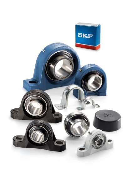
112
113 Y-bearing plummer block units Designs Y-TECH plummer block units Y-bearing plummer block units with a cast housing Y-bearing plummer block units with a pressed steel housing Data general Dimensions Tolerances Radial internal clearance Materials Load carrying ability of the housings End covers Attaching to a support surface Grease fills Mounting Product tables Y-TECH plummer block units with grub screws, metric shafts Y-bearing plummer block units with a cast housing and grub screws, metric shafts inch shafts Y-bearing plummer block units with a cast housing and an eccentric locking collar metric shafts inch shafts Y-bearing plummer block units with a cast housing and an adapter sleeve, metric shafts inch shafts Y-bearing plummer block units with a shortened cast housing and grub screws, metric shafts Y-bearing plummer block units with a shortened cast housing and an eccentric locking collar, metric shafts Y-bearing plummer block units with a pressed steel housing and grub screws, metric shafts inch shafts Y-bearing plummer block units with a pressed steel housing and an eccentric locking collar, metric shafts inch shafts
 referred to as Y-TECH plummer block units grey cast iron ( fig.")
 They are located on the shaft via the inner ring of the insert bearing with either: grub (set) screws an eccentric locking collar an adapter sleeve The Y-bearing can")

114 Y-bearing plummer block units Designs Fig. 1 SKF Y-bearing plummer (pillow) block units are available as standard in a wide variety of designs. The standard assortment includes plummer block units with housings made of: composite material ( fig. 1) referred to as Y-TECH plummer block units grey cast iron ( fig. 2) pressed sheet steel ( fig. 3) They are located on the shaft via the inner ring of the insert bearing with either: grub (set) screws an eccentric locking collar an adapter sleeve The Y-bearing can be sealed with either: Fig. 2 the standard integral seal the standard integral seal and an additional flinger the highly efficient multiple seal Additional information about Y-bearings can be found in the section Y-bearings, starting on page 79. Y-bearing plummer block units available from stock are listed in the product tables. Other units can be composed by ordering the parts separately. The table on pages 114 and 115 shows the wide variety of combinations of Y-bearings and Y-bearing housings. Fig


115 Y-TECH plummer block units Fig. 4 Y-TECH plummer block units have housings made of composite material. They were developed for bearing arrangements that must operate reliably in difficult environments for extended periods without maintenance. Y-TECH plummer block units in the SYK series are fitted with Y-bearings in the YAR 2-2F or YAR 2-2RF series and are attached to the shaft with grub screws ( fig. 4). These units are part of the standard SKF product range. For additional information about Y-TECH plummer block units for the food industry, refer to page Y-bearing plummer block units with a cast housing Y-bearing plummer block units with a grey cast iron housing can be relubricated through a grease fitting in the housing. This makes them especially suitable for bearing arrangements that operate under any of the following conditions: Fig. 5 high levels of contamination high speeds high temperatures relatively heavy loads Four different housing designs are available: SY(J) series with two oblong holes for the attachment bolts in the base of the housing ( fig. 5) SYH series, which is similar to the SY series, but with a lower centre height SYM series, which is similar to the SY series, but accommodates a larger bearing for a given shaft size, resulting in a greater load carrying capacity SYF(J) series with a shortened base that contains two threaded holes in the support base ( fig. 6) Fig
116 Y-bearing plummer block units Y-bearing unit Y-bearing housings Y-bearings SYK 5(00) SY 5(00) SYJ 5(00) SYH 5(00) SYM 5(00) SYF 5(00) YAR 2-2F SYK.. TF mm SY.. TF mm 1/ /16 in. SYJ.. TF SYH.. TF mm 3/4 2 1 /2 in. 1/2 2 7 /16 in. SYM.. TF 1 7 /16 3 in. SYF.. TF mm 3/4 1 3 /4 in. 1) YAR 2-2RF SYK.. TR mm SY.. TR mm mm 1) mm 1) 3/4 2 1 /2 in. 1) 3/4 2 1 /2 in. 1) 3/4 1 3 /4 in. 1) YAR 2-2RF/HV mm 1) mm 1) mm 1) mm 1) 3/4 1 1 /2 in. 1) 3/4 1 1 /2 in. 1) 3/4 1 1 /2 in. 1) 3/4 1 1 /2 in. 1) YAR 2-2RF/ VE mm 1) mm 1) mm 1) mm 1) YAT mm 1) mm 1) mm 1) mm 1) YEL 2-2F mm 1) SY.. WF mm 1 7 / /16 in mm 1) SYH.. WF 3/4 2 7 /16 in mm 1) YEL 2-2RF/ VL mm 1) mm 1) mm 1) mm 1) YET 2 SY.. FM SYH.. FM mm 1) mm mm 1) 3/4 1 1 /2 in. 1) 3/4 1 1 /2 in. 1) 1 2 in. SYF.. FM mm 3/4 1 1 /2 in. 1) YSA 2-2FK on adapter sleeve 1 /4 /8 3/4 2 3 /8 in mm 1) 3/4 1 in. 1) mm 1) 3/4 2 in. 1) SYJ.. KF mm mm 1) 3/4 1 3 /4 in. 1) 17262(00) mm 1) mm 1) mm 1) mm 1) 1) Parts must be ordered separately. 114
117 Y-bearing unit Y-bearing housings Y-bearings SYFJ 5(00) P 40 P 85 YAR 2-2F SYFJ.. TF mm 3/4 1 3 /4 in. 1) mm 1) 1/2 1 3 /4 in. 1) YAR 2-2RF YAR 2-2RF/HV mm 1) 3/4 1 3 /4 in. 1) mm 1) 3/4 1 3 /4 in. 1) mm 1) 3/4 1 1 /2 in. 1) mm 1) 3/4 1 1 /2 in. 1) 3 YAR 2-2RF/ VE mm 1) mm 1) YAT mm 1) mm 1) 5/8 1 3 /4 in. 1) YEL 2-2F mm 1) mm 1) 1/2 1 3 /4 in. 1) YEL 2-2RF/ VL mm 1) mm 1) YET 2 SYFJ.. FM mm 3/4 1 1 /2 in. 1) mm 1) 1/2 1 3 /4 in. 1) YSA 2-2FK on adapter sleeve mm 1) 3/4 1 3 /4 in. 1) mm 1) 3/4 1 1 /2 in. 1) 17262(00) mm 1) mm 1) 1) Parts must be ordered separately. 115
 with a pressed steel housing are designed for simple applications with limited loads and speeds.")
118 Y-bearing plummer block units Y-bearing plummer block units with a pressed steel housing Fig. 7 Y-bearing plummer block units ( fig. 7) with a pressed steel housing are designed for simple applications with limited loads and speeds. The two-part housing, which has no provision for relubrication, is ordered separately from the insert bearing. The individual items that make up a Y-bearing unit are: the two-part housing the Y-bearing the rubber seating ring, if needed The advantage of ordering individual components is that a large number of combinations are possible. Rubber seating rings made of acrylonitrilebutadiene rubber in the RIS 2 series ( fig. 8) are available for these Y-bearing plummer blocks and are meant to reduce running noise and dampen vibration. The rubber seating rings also enable the bearings to be displaced slightly in their housings, for example, to accommodate shaft elongation. Y-bearing units with a rubber seating ring are also listed in the product tables. Detailed information about rubber seating rings can be found in the section Design of Y-bearing arrangements on pages 45 and 46. Data general Dimensions The boundary dimensions of most Y-bearing plummer block housings are in accordance with the following standards: Housings in the SY 5(00) M series are in accordance with ISO 3228:1993. Housings in the SY 5(00) U series are in accordance with ISO 3228:1993, except the centre height H 1, which deviates for several housing sizes. Housings in the SYH series are in accordance with ISO 3228:1993, except the centre height H 1, which is lower than the standard. Fig. 8 Housings in the SYJ series are in accordance with JIS B Housings in the P series are in accordance with ISO 3228:1993, except the centre height H 1, which deviates slightly. Y-bearing plummer block housings in the SYF, SYFJ and SYM series have not been standardized either nationally or internationally, but are common in the marketplace. 116
119 Tolerances The tolerance for the shaft centre height H 1 ( fig. 9) is Fig. 9 ±0,25 mm for plummer block units with a bearing bore diameter 40 mm, except for units in the SYK series, where the tolerance is +/ 0,31 mm ±0,30 mm for the larger plummer block units. For Y-bearing plummer block units with composite or cast housings, the outside diameter of the bearing is matched to the diameter of the housing bore so that the outer ring is prevented from turning in its seat, but still able to compensate for misalignment. Additional information about tolerances for the inner ring bore are listed in the section Y-bearings on page 89. Radial internal clearance The Y-bearing used in a Y-bearing plummer block unit has the same radial internal clearance as a similarly sized individual Y-bearing. Additional information about the radial internal clearance can be found in the section Y-bearings on page 90. Materials Composite housings Y-housings in the SYK series are made of injection moulded glass fibre reinforced polyamide 6. A steel coil embedded in the housing adds greater stability to the form of the housing, even if operating temperatures are elevated. The housing bolt holes are reinforced with zinc-plated sheet steel inserts. The standard housing colour is black. Cast housings Housings in the SY(J), SYH, SYM and SYF(J) series are manufactured from grey cast iron EN-GJL HB195 in accordance with EN 1561:1997. Pressed steel housings Pressed steel housings in the P series are made from cold-rolled sheet steel and are zinc-coated for corrosion protection. H 1 Load carrying ability of the housings Housings made of composite material or grey cast iron are able to withstand the same dynamic and static loads as the Y-bearings they incorporate. These Y-bearing units can also be used in applications where shock loads or variable axial loads occur. If SKF Y-bearing units are to be used in an application where health, safety, or the environment is at risk, contact the SKF application engineering service during the design phase. Pressed steel housings have a lower load carrying capacity than their insert bearings. Permissible radial loads are specified in the product tables. The axial load should not exceed 20% of the permissible radial load. If the bearing arrangement will be subjected to shock loads or variable axial loads, Y-bearing units with a cast or Y-TECH housing should always be used
120 Y-bearing plummer block units End covers To protect the shaft ends and avoid contact to rotating shaft ends, end covers are available for composite and cast Y-bearing plummer block units ( fig. 10). In the product tables, end covers in the ECY 2 series are shown together with the appropriate bearing unit. The designation of the end cover is listed together with the distance that the end cover protrudes from the housing. For additional information about end covers, refer to the section Design of Y-bearing arrangements on page 47. Fig. 10 Attaching to a support surface Plummer block units have two bolt holes in the housing base through which they can be attached to their support surface with threaded fasteners. The bolt holes vary for different housings. Housings made of: Fig. 11 composite material have oblong bolt holes, reinforced with zinc-coated sheet steel or stainless steel inserts grey cast iron SY(J), SYH and SYM series have cast oblong bolt holes grey cast iron SYF and SYFJ series have threaded holes in the support base pressed steel have round bolt holes If the loads acting on a housing are between 55 and 120 ( fig. 11), Y-TECH bearing units and SY(J), SYH and SYM plummer block units should be doweled to the support surface or stops should be provided in the direction of the load. Recommendations for the position and size of the dowel pin holes for SY, SYJ and SYH series housings are provided in table 1. Grease fills With the exception of SKF Y-bearing units for the food industry, all standard SKF Y-bearing plummer block units are filled with a highquality, long-lasting grease containing a lithiumcalcium thickener that has a consistency of 2 on the NLGI scale. For additional information about lubricants and lubrication, refer to the section Lubrication and maintenance, starting on page 48. P 120 P 55 Mounting The procedure for mounting a Y-bearing plummer block unit depends on: the design of the housing the method used to attach the unit to the shaft These methods are described in detail in the section Mounting instructions, starting on page
121 J 7 N 4 Table 1 Position and size of dowel pin holes for Y-bearing plummer block housings made of grey cast iron J 6 Housing Dimensions for housings in the size SYJ series SY, SYH series J 6 J 7 N 4 J 6 J 7 N 4 3 mm , , , , , , , , ,
122 Y-TECH plummer block units with grub screws, metric shafts d mm J A 1 N 1 d s 1 B H N H 1 H 2 A G J TF TR L Dimensions Basic load Fatigue Limiting Designation ratings load speed Bearing unit dynamic static limit with shaft d A A 1 B H H 1 H 2 J L N N 1 G s 1 C C 0 P u tolerance h6 mm kn kn r/min , , ,3 12,7 6,55 0, SYK 20 TF , , ,3 12,7 6,55 0, SYK 20 TR ,1 70,5 36, , ,8 14 7,8 0, SYK 25 TF ,1 70,5 36, , ,8 14 7,8 0, SYK 25 TR , , ,5 14, ,2 19,5 11,2 0, SYK 30 TF , , ,5 14, ,2 19,5 11,2 0, SYK 30 TR , , ,5 14, ,4 25,5 15,3 0, SYK 35 TF , , ,5 14, ,4 25,5 15,3 0, SYK 35 TR , , ,5 14, ,2 30,7 19 0, SYK 40 TF , , ,5 14, ,2 30,7 19 0, SYK 40 TR 120
123 A Designations Mass Appropriate end cover Bearing unit Separate components Bearing Designation Dimension Housing Bearing unit A 5 kg mm SYK 20 TF SYK 504 YAR 204-2F 0,24 ECY ,5 SYK 20 TR SYK 504 YAR 204-2RF 0,24 ECY ,5 SYK 25 TF SYK 505 YAR 205-2F 0,29 ECY SYK 25 TR SYK 505 YAR 205-2RF 0,29 ECY SYK 30 TF SYK 506 YAR 206-2F 0,49 ECY SYK 30 TR SYK 506 YAR 206-2RF 0,49 ECY SYK 35 TF SYK 507 YAR 207-2F 0,66 ECY SYK 35 TR SYK 507 YAR 207-2RF 0,66 ECY SYK 40 TF SYK 508 YAR 208-2F 0,86 ECY ,5 SYK 40 TR SYK 508 YAR 208-2RF 0,86 ECY ,5 121
124 Y-bearing plummer block units with a cast housing and grub screws, metric shafts d mm J A 1 N 1 d s 1 B H G N H 1 H 2 A J L TF TR Dimensions Basic load Fatigue Limiting Designation ratings load speed Bearing unit dynamic static limit with shaft d A A 1 B H H 1 H 2 J L N N 1 G s 1 C C 0 P u tolerance h6 mm kn kn r/min , , ,5 11, ,9 9,56 4,75 0, SY 12 TF , , ,5 11, ,9 9,56 4,75 0, SY 15 TF , , ,5 11, ,9 9,56 4,75 0, SY 17 TF , ,5 11, ,3 12,7 6,55 0, SY 20 TF , , ,3 12,7 6,55 0, SYJ 20 TF , ,5 11, ,3 12,7 6,55 0, SY 20 TR ,1 70,5 36, ,5 11, ,8 14 7,8 0, SY 25 TF ,1 70,5 36, , , ,8 14 7,8 0, SYJ 25 TF ,1 70,5 36, ,5 11, ,8 14 7,8 0, SY 25 TR ,1 82,5 42, , , ,2 19,5 11,2 0, SY 30 TF ,1 82,5 42, ,2 19,5 11,2 0, SYJ 30 TF ,1 82,5 42, , , ,2 19,5 11,2 0, SY 30 TR , , ,4 25,5 15,3 0, SY 35 TF , , ,4 25,5 15,3 0, SYJ 35 TF , , ,4 25,5 15,3 0, SY 35 TR , , , , ,2 30,7 19 0, SY 40 TF , , , , ,2 30,7 19 0, SYJ 40 TF , , , , ,2 30,7 19 0, SY 40 TR ,2 107, , , ,2 33,2 21,6 0, SY 45 TF ,2 107, , , ,2 33,2 21,6 0, SYJ 45 TF ,2 107, , , ,2 33,2 21,6 0, SY 45 TR ,6 114,5 57, ,6 35,1 23,2 0, SY 50 TF ,6 114,5 57, , , ,6 35,1 23,2 0, SYJ 50 TF ,6 114,5 57, ,6 35,1 23,2 0, SY 50 TR , , , , ,4 43,6 29 1, SY 55 TF , , , , ,4 43,6 29 1, SYJ 55 TF , , , , ,4 43,6 29 1, SY 55 TR , ,8 26,5 190, , ,7 52,7 36 1, SY 60 TF , ,8 26,5 188, , ,7 52,7 36 1, SYJ 60 TF , ,8 26,5 190, , ,7 52,7 36 1, SY 60 TR 122
125 A Designations Mass Appropriate end cover Bearing unit Separate components Bearing Designation Dimension Housing Bearing unit A 5 kg mm SY 12 TF SY 503 M YAR 203/12-2F 0,52 SY 15 TF SY 503 M YAR 203/15-2F 0,51 SY 17 TF SY 503 M YAR 203-2F 0,50 SY 20 TF SY 504 M YAR 204-2F 0,57 ECY ,5 SYJ 20 TF SYJ 504 YAR 204-2F 0,55 SY 20 TR SY 504 M YAR 204-2RF 0,57 ECY ,5 SY 25 TF SY 505 M YAR 205-2F 0,72 ECY SYJ 25 TF SYJ 505 YAR 205-2F 0,73 SY 25 TR SY 505 M YAR 205-2RF 0,72 ECY SY 30 TF SY 506 M YAR 206-2F 1,10 ECY SYJ 30 TF SYJ 506 YAR 206-2F 1,05 SY 30 TR SY 506 M YAR 206-2RF 1,10 ECY SY 35 TF SY 507 M YAR 207-2F 1,45 ECY SYJ 35 TF SYJ 507 YAR 207-2F 1,50 SY 35 TR SY 507 M YAR 207-2RF 1,45 ECY SY 40 TF SY 508 M YAR 208-2F 1,80 ECY ,5 SYJ 40 TF SYJ 508 YAR 208-2F 1,85 SY 40 TR SY 508 M YAR 208-2RF 1,80 ECY ,5 SY 45 TF SY 509 M YAR 209-2F 2,20 ECY SYJ 45 TF SYJ 509 YAR 209-2F 2,40 SY 45 TR SY 509 M YAR 209-2RF 2,20 ECY SY 50 TF SY 510 M YAR 210-2F 2,70 ECY ,5 SYJ 50 TF SYJ 510 YAR 210-2F 2,95 SY 50 TR SY 510 M YAR 210-2RF 2,70 ECY ,5 SY 55 TF SY 511 M YAR 211-2F 3,60 ECY SYJ 55 TF SYJ 511 YAR 211-2F 3,70 SY 55 TR SY 511 M YAR 211-2RF 3,60 ECY SY 60 TF SY 512 M YAR 212-2F 4,45 ECY ,5 SYJ 60 TF SYJ 512 YAR 212-2F 4,85 SY 60 TR SY 512 M YAR 212-2RF 4,45 ECY ,5 123
126 Y-bearing plummer block units with a cast housing and grub screws, metric shafts d mm J A 1 N 1 d s 1 B H G N H 1 H 2 A J L TF Dimensions Basic load Fatigue Limiting Designation ratings load speed Bearing unit dynamic static limit with shaft d A A 1 B H H 1 H 2 J L N N 1 G s 1 C C 0 P u tolerance h6 mm kn kn r/min , , ,9 57,2 40 1, SY 65 TF , , ,9 57,2 40 1, SYJ 65 TF , , ,7 62,4 45 1, SYJ 70 TF , , ,1 66,3 49 2, SYJ 75 TF , , ,7 72,8 53 2, SYJ 80 TF , ,6 72 2, SYJ 90 TF , , , SYJ 100 TF 124
127 A Designations Mass Appropriate end cover Bearing unit Separate components Bearing Designation Dimension Housing Bearing unit A 5 kg mm SY 65 TF SY 513 M YAR 213-2F 5,70 ECY ,5 SYJ 65 TF SYJ 513 YAR 213-2F 6,15 SYJ 70 TF SYJ 514 YAR 214-2F 6,20 SYJ 75 TF SYJ 515 YAR 215-2F 7,30 SYJ 80 TF SYJ 516 YAR 216-2F 9,70 SYJ 90 TF SYJ 518 YAR 218-2F 14,0 SYJ 100 TF SYJ 520 YAR 220-2F 19,0 125
128 Y-bearing plummer block units with a cast housing and grub screws, inch shafts d 1 /2 1 3 /16 in J A 1 N 1 d s 1 B H G N H 1 H 2 A J L TF TR Dimensions Designation Bearing unit d A A 1 B H H 1 H 2 J L N N 1 G s 1 in/mm 1/ / SY 1/2 TF 12, , , ,5 11, , / SYH 1/2 TF , , ,5 11, ,9 3/ / SY 3/4 TF 19, , ,5 11, , / SYJ 3/4 TF , , ,3 5/ / SY 5/8 TF 15, , , ,5 11, ,9 13/ / SY 13/16 TF 20, , , ,5 11, ,8 7/ / SY 7/8 TF 22, , , ,5 11, ,8 15/ / SY 15/16 TF 23, , , ,5 11, , / SY 1. TF 25, ,1 70,5 36, ,5 11, , / SY 1. TF/AH , , ,5 11, , / SYJ 1. TF ,1 70,5 36, , , / SY 1. TR ,1 70,5 36, ,5 11, ,8 1 1 / / SY 1.1/16 TF 26, , ,9 16,5 117, , ,2 1 1 / / SY 1.1/8 TF 28, , ,2 16,5 117, , ,2 1 3 / / SY 1.3/16 TF 30, , ,9 16,5 117, , , / SY 1.3/16 TF/AH , ,9 16,5 117, , ,2 126
129 3.2 Designations Basic load Fatigue Limiting Mass Bearing unit Separate components ratings load speed Bearing Housing Bearing dynamic static limit with shaft unit C C 0 P u tolerance h6 lbf/kn lbf/kn r/min lb/kg SY 1/2 TF SY 503 U YAR F ,56 4,75 0,2 0,55 SYH 1/2 TF SYH 503 U YAR F ,56 4,75 0,2 0,55 SY 3/4 TF SY 504 M YAR F ,7 6,55 0,28 0,56 SYJ 3/4 TF SYJ 504 YAR F ,7 6,55 0,28 0,54 SY 5/8 TF SY 503 U YAR F ,56 4,75 0,2 0,51 SY 13/16 TF SY 505 U YAR F ,8 0,335 0,84 SY 7/8 TF SY 505 U YAR F ,8 0,335 0,81 SY 15/16 TF SY 505 U YAR F ,8 0,335 0,78 SY 1. TF SY 505 M YAR F ,8 0,335 0,71 SY 1. TF/AH SY 505 U/AH YAR F/AH ,8 0,335 0,72 SYJ 1. TF SYJ 505 YAR F ,8 0,335 0,73 SY 1. TR SY 505 M YAR RF ,8 0,335 0,72 SY 1.1/16 TF SY 506 U YAR F ,5 11,2 0,475 1,20 SY 1.1/8 TF SY 506 U YAR F ,5 11,2 0,475 1,20 SY 1.3/16 TF SY 506 U YAR F ,5 11,2 0,475 1,20 SY 1.3/16 TF/AH SY 506 U/AH YAR F/AH ,5 11,2 0,475 1,20 127
130 Y-bearing plummer block units with a cast housing and grub screws, inch shafts d 1 1 /4 1 5 /8 in J A 1 N 1 d s 1 B H G N H 1 H 2 A J L TF TR Dimensions Designation Bearing unit d A A 1 B H H 1 H 2 J L N N 1 G s 1 in/mm 1 1 / / SY 1.1/4 TF 31, , , , / SYJ 1.1/4 TF , , , / SY 1.1/4 TR , , ,4 1 5 / / SY 1.5/16 TF 33, , , ,4 1 3 / / SY 1.3/8 TF 34, , , ,4 1 7 / / SY 1.7/16 TF 36, , , , / SYM 1.7/16 TF 47,6 28,6 49, ,6 143,7 187,5 24, ,2 1 1 / / SY 1.1/2 TF 38, , , , , , / SY 1.1/2 TF/AH , , , , , / SYJ 1.1/2 TF , , , , , / SYM 1.1/2 TF 47, , ,6 143,7 187,5 22, , / SY 1.1/2 TR , , , , ,2 1 9 / / SY 1.9/16 TF 39, , , , , ,2 1 5 / / SY 1.5/8 TF 41,275 48, , ,6 143, , ,2 128
131 Designations Basic load Fatigue Limiting Mass Bearing unit Separate components ratings load speed Bearing Housing Bearing dynamic static limit with shaft unit C C 0 P u tolerance h6 lbf/kn lbf/kn r/min lb/kg SY 1.1/4 TF SY 507 M YAR F ,5 15,3 0,655 1,50 SYJ 1.1/4 TF SYJ 507 YAR F ,5 15,3 0,655 1,55 SY 1.1/4 TR SY 507 M YAR RF ,5 15,3 0,655 1,50 SY 1.5/16 TF SY 507 U YAR F ,5 15,3 0,655 1,65 SY 1.3/8 TF SY 507 U YAR F ,5 15,3 0,655 1,50 SY 1.7/16 TF SY 507 U YAR F ,5 15,3 0,655 1,60 SYM 1.7/16 TF SYM 508 U YAR F ,7 19 0,8 2,40 SY 1.1/2 TF SY 508 M YAR F ,7 19 0,8 1,85 SY 1.1/2 TF/AH SY 508 U/AH YAR F/AH ,7 19 0,8 1,80 SYJ 1.1/2 TF SYJ 508 YAR F ,7 19 0,8 1,90 SYM 1.1/2 TF SYM 509 U YAR F ,2 21,6 0,915 2,55 SY 1.1/2 TR SY 508 M YAR RF ,7 19 0,8 1,85 SY 1.9/16 TF SY 508 U YAR F ,7 19 0,8 1,95 SY 1.5/8 TF SY 509 U YAR F ,2 21,6 0,915 2,45 129
132 Y-bearing plummer block units with a cast housing and grub screws, inch shafts d 1 11 / /4 in J A 1 N 1 d s 1 B H G N H 1 H 2 A J L TF Dimensions Designation Bearing unit d A A 1 B H H 1 H 2 J L N N 1 G s 1 in/mm 1 11 / / SY 1.11/16 TF 42,862 48, , ,6 143, , , / SY 1.11/16 TF/AH 48, , ,6 143, , , / SYM 1.11/16 TF ,6 114,5 57,2 22,2 157, ,6 1 3 / / SY 1.3/4 TF 44, ,2 107, , , , / SYJ 1.3/4 TF ,2 107, , , , / SYM 1.3/4 TF , , , / / SY 1.15/16 TF 49, , , , / SY 1.15/16 TF/AH , , , / SYH 1.15/16 TF ,6 113,5 55,6 21, , / SYM 1.15/16 TF 60, , ,5 23,8 171, , , / SY 2. TF 50, , , , , , / SYJ 2. TF , , , , , / SY 2. TF/AH 60, , ,5 23,8 171, , ,4 2 3 / / SY 2.3/16 TF 55,563 60, , ,5 23,8 171, , , / SY 2.3/16 TF/AH 60, , ,5 23,8 171, , , / SYM 2.3/16 TF ,1 139,5 69, , , ,7 2 1 / / SY 2.1/4 TF 57, ,1 139,5 69, , , , / SYH 2.1/4 TF , ,3 25,4 190, , ,7 130
133 Designations Basic load Fatigue Limiting Mass Bearing unit Separate components ratings load speed Bearing Housing Bearing dynamic static limit with shaft unit C C 0 P u tolerance h6 lbf/kn lbf/kn r/min lb/kg SY 1.11/16 TF SY 509 U YAR F ,2 21,6 0,915 2,40 SY 1.11/16 TF/AH SY 509 U/AH YAR F/AH ,2 21,6 0,915 2,40 SYM 1.11/16 TF SYM 510 U YAR F ,1 23,2 0,98 3,00 SY 1.3/4 TF SY 509 M YAR F ,2 21,6 0,915 2,20 SYJ 1.3/4 TF SYJ 509 YAR F ,2 21,6 0,915 2,40 SYM 1.3/4 TF SY 510 U YAR F ,1 23,2 0,98 3,05 SY 1.15/16 TF SY 510 U YAR F ,1 23,2 0,98 2,85 SY 1.15/16 TF/AH SY 510 U/AH YAR F/AH ,1 23,2 0,98 2,85 SYH 1.15/16 TF SYH 510 U YAR F ,1 23,2 0,98 2,90 SYM 1.15/16 TF SY 511 U YAR F ,6 29 1,25 4,00 SY 2. TF SY 511 M YAR F ,6 29 1,25 3,75 SYJ 2. TF SYJ 511 YAR F ,6 29 1,25 3,85 SY 2. TF/AH SY 511 U/AH YAR F/AH ,6 29 1,25 4,00 SY 2.3/16 TF SY 511 U YAR F ,6 29 1,25 3,60 SY 2.3/16 TF/AH SY 511 U/AH YAR F/AH ,6 29 1,25 3,80 SYM 2.3/16 TF SY 512 U YAR F ,7 36 1,53 5,45 SY 2.1/4 TF SY 512 U YAR F ,7 36 1,53 5,45 SYH 2.1/4 TF SYH 512 U YAR F ,7 36 1,53 4,70 131
134 Y-bearing plummer block units with a cast housing and grub screws, inch shafts d 2 7 /16 3 in J A 1 N 1 d s 1 B H G N H 1 H 2 A J L TF Dimensions Designation Bearing unit d A A 1 B H H 1 H 2 J L N N 1 G s 1 in/mm 2 7 / / SY 2.7/16 TF 61, ,1 139,5 69, , , , / SYH 2.7/16 TF , ,3 25,4 190, , , / SYM 2.7/16 TF ,9 153,5 76,2 38,1 203, , ,7 2 1 / / SY 2.1/2 TF 63, , , , / SYJ 2.1/2 TF , , , / SYM 2.1/2 TF ,9 153,5 76,2 39,1 203, , , / / SY 2.11/16 TF 68, , , , / SYM 2.11/16 TF 76, , ,9 47,2 228, , ,1 2 3 / / SY 2.3/4 TF 69,85 71, , ,6 32,8 215, , , / / SY 2.15/16 TF 74,613 71, , ,6 32,8 215, , , / SYM 2.15/16 TF , ,9 47,6 228, , , / SYM 3. TF 76, , ,9 47,6 228, , ,7 132
135 Designations Basic load Fatigue Limiting Mass Bearing unit Separate components ratings load speed Bearing Housing Bearing dynamic static limit with shaft unit C C 0 P u tolerance h6 lbf/kn lbf/kn r/min lb/kg SY 2.7/16 TF SY 512 U YAR F ,7 36 1,53 4,55 SYH 2.7/16 TF SYH 512 U YAR F ,7 36 1,53 4,65 SYM 2.7/16 TF SY 514 U YAR F ,4 44 1,86 7,25 SY 2.1/2 TF SY 513 M YAR F ,2 40 1,7 5,80 SYJ 2.1/2 TF SYJ 513 YAR F ,2 40 1,7 6,25 SYM 2.1/2 TF SY 514 U YAR F ,4 44 1,86 7,00 SY 2.11/16 TF SY 513 U YAR F ,2 40 1,7 5,70 SYM 2.11/16 TF SYM 515 U YAR F ,3 49 2,04 10,8 SY 2.3/4 TF SY 515 U YAR F ,3 49 2,04 8,00 SY 2.15/16 TF SY 515 U YAR F ,8 53 2,04 7,55 SYM 2.15/16 TF SY 516 U YAR F ,8 53 2,16 10,3 SYM 3. TF SY 516 U YAR F ,8 53 2,16 10,2 133
136 Y-bearing plummer block units with a cast housing and an eccentric locking collar, metric shafts d mm J A 1 N 1 d s 1 B 1 H G N H 1 H 2 A J FM WF L Dimensions Basic load Fatigue Limiting Designation ratings load speed Bearing dynamic static limit with shaft unit d A A 1 B 1 H H 1 H 2 J L N N 1 G s 1 C C 0 P u tolerance h6 mm kn kn r/min , , ,5 11, ,1 9,56 4,75 0, SY 15 FM , , ,5 11, ,1 9,56 4,75 0, SY 17 FM , ,5 11, ,5 12,7 6,55 0, SY 20 FM , , ,5 11, ,6 12,7 6,55 0, SY 20 WF ,5 36, ,5 11, ,5 14 7,8 0, SY 25 FM ,4 70,5 36, ,5 11, ,9 14 7,8 0, SY 25 WF ,7 82,5 42, , , ,7 19,5 11,2 0, SY 30 FM ,4 82,5 42, , , ,1 19,5 11,2 0, SY 30 WF , , ,4 25,5 15,3 0, SY 35 FM , , ,3 25,5 15,3 0, SY 35 WF , , , , ,7 30,7 19 0, SY 40 FM , , , , ,9 30,7 19 0, SY 40 WF ,7 107, , , ,7 33,2 21,6 0, SY 45 FM ,3 107, , , ,9 33,2 21,6 0, SY 45 WF ,7 114,5 57, ,7 35,1 23,2 0, SY 50 FM ,7 114,5 57, ,1 35,1 23,2 0, SY 50 WF , , , , ,4 43,6 29 1, SY 55 FM , , , , ,6 43,6 29 1, SY 55 WF , ,9 26,5 190, , ,6 52,7 36 1, SY 60 FM , ,9 26,5 190, , ,8 52,7 36 1, SY 60 WF 134
137 A Designations Mass Appropriate end cover Bearing unit Separate components Bearing Designation Dimension Housing Bearing unit A 5 kg mm SY 15 FM SY 503 M YET 203/15 0,53 SY 17 FM SY 503 M YET 203 0,52 SY 20 FM SY 504 M YET 204 0,59 ECY ,5 SY 20 WF SY 504 M YEL 204-2F 0,62 ECY ,5 SY 25 FM SY 505 M YET 205 0,73 ECY SY 25 WF SY 505 M YEL 205-2F 0,78 ECY SY 30 FM SY 506 M YET 206 1,10 ECY SY 30 WF SY 506 M YEL 206-2F 1,20 ECY SY 35 FM SY 507 M YET 207 1,55 ECY SY 35 WF SY 507 M YEL 207-2F 1,60 ECY SY 40 FM SY 508 M YET 208 1,85 ECY ,5 SY 40 WF SY 508 M YEL 208-2F 1,95 ECY ,5 SY 45 FM SY 509 M YET 209 2,25 ECY SY 45 WF SY 509 M YEL 209-2F 2,35 ECY SY 50 FM SY 510 M YET 210 2,75 ECY ,5 SY 50 WF SY 510 M YEL 210-2F 2,90 ECY ,5 SY 55 FM SY 511 M YET 211 3,65 ECY SY 55 WF SY 511 M YEL 211-2F 3,90 ECY SY 60 FM SY 512 M YET 212 4,45 ECY ,5 SY 60 WF SY 512 M YEL 212-2F 4,75 ECY ,5 135
138 Y-bearing plummer block units with a cast housing and an eccentric locking collar, inch shafts d 1 /2 1 5 /16 in J A 1 N 1 d s 1 B 1 H G N H 1 H 2 A J FM WF L Dimensions d A A 1 B 1 H H 1 H 2 J L N N 1 G s 1 Designation Bearing unit in/mm 1/ / SY 1/2 FM 12, , , ,5 11, ,1 3/ / SY 3/4 FM 19, , ,5 11, / SYH 3/4 WF ,7 62,5 31,8 12, ,5 11, ,6 15/ / SY 15/16 FM 23, , ,5 11, , / SYH 1. FM 25, ,4 12, ,5 11, , , / SYH 1. WF , ,4 12, ,5 11, ,9 1 1 / / SY 1.1/8 FM 28, , ,9 16,5 117, , , / SYH 1.1/8 WF , ,7 14,8 117, , ,1 1 3 / / SY 1.3/16 FM 30, , ,9 16,5 117, , , / SYH 1.3/16 FM , ,7 14,8 117, , , / SYH 1.3/16 WF , ,7 14,8 117, , ,1 1 1 / / SY 1.1/4 FM 31, , , , / SYH 1.1/4 FM ,9 91,5 46,1 17, , / SYH 1.1/4 WF ,1 91,5 46,1 17, ,3 1 5 / / SY 1.5/16 FM 33, , , ,4 136
139 3.3 Designations Basic load Fatigue Limiting Mass Bearing unit Separate components ratings load speed Bearing Housing Bearing dynamic static limit with shaft unit C C 0 P u tolerance h6 lbf/kn lbf/kn r/min lb/kg SY 1/2 FM SY 503 U YET ,56 4,75 0,2 0,60 SY 3/4 FM SY 504 U YET ,7 6,55 0,28 0,62 SYH 3/4 WF SYH 504 U YEL F ,7 6,55 0,28 0,66 SY 15/16 FM SY 505 U YET ,8 0,335 0,75 SYH 1. FM SYH 505 U YET ,8 0,335 0,74 SYH 1. WF SYH 505 U YEL F ,8 0,335 0,79 SY 1.1/8 FM SY 506 U YET ,5 11,2 0,475 1,10 SYH 1.1/8 WF SYH 506 U YEL F ,5 11,2 0,475 1,45 SY 1.3/16 FM SY 506 U YET ,5 11,2 0,475 1,10 SYH 1.3/16 FM SYH 506 U YET ,5 11,2 0,475 1,15 SYH 1.3/16 WF SYH 506 U YEL F ,5 11,2 0,475 1,20 SY 1.1/4 FM SY 507 U YET ,5 15,3 0,655 1,70 SYH 1.1/4 FM SYH 507 U YET ,5 15,3 0,655 1,60 SYH 1.1/4 WF SYH 507 U YEL F ,5 15,3 0,655 1,85 SY 1.5/16 FM SY 507 U YET ,5 15,3 0,655 1,65 137
140 Y-bearing plummer block units with a cast housing and an eccentric locking collar, inch shafts d 1 3 /8 2 in J A 1 N 1 d s 1 B 1 H G N H 1 H 2 A J FM WF L Dimensions d A A 1 B 1 H H 1 H 2 J L N N 1 G s 1 Designation Bearing unit in/mm 1 3 / / SY 1.3/8 FM 34, , , , / SYH 1.3/8 WF ,1 91,5 46,1 17, ,3 1 7 / / SY 1.7/16 FM 36, , , , / SY 1.7/16 WF , , , / SYH 1.7/16 FM ,9 91,5 46,1 17, , / SYH 1.7/16 WF ,1 91,5 46,1 17, ,3 1 1 / / SY 1.1/2 FM 38, , , , , , / SYH 1.1/2 WF , , , , , / / SY 1.11/16 FM 42,863 48, , ,6 143, , , / SYH 1.11/16 WF 48, ,3 105,5 52, , , ,9 1 3 / / SY 1.3/4 FM 44,45 48, , ,6 143, , , / SYH 1.3/4 WF 48, ,3 105,5 52, , , , / / SY 1.15/16 FM 49, , , , / SY 1.15/16 WF , , , / SYH 1.15/16 WF ,7 113,5 55,6 21, , / SY 2. FM 50,8 60, , ,5 23,8 171, , , / SYH 2. FM 60, ,4 126,5 61,9 23,3 171, , , / SYH 2. WF 60, ,4 126,5 61,9 23,3 171, , ,6 138
141 3.3 Designations Basic load Fatigue Limiting Mass Bearing unit Separate components ratings load speed Bearing Housing Bearing dynamic static limit with shaft unit C C 0 P u tolerance h6 lbf/kn lbf/kn r/min lb/kg SY 1.3/8 FM SY 507 U YET ,5 15,3 0,655 1,65 SYH 1.3/8 WF SYH 507 U YEL F ,5 15,3 0,655 1,80 SY 1.7/16 FM SY 507 U YET ,5 15,3 0,655 1,63 SY 1.7/16 WF SY 507 U YEL F ,5 15,3 0,655 1,70 SYH 1.7/16 FM SYH 507 U YET ,5 15,3 0,655 1,55 SYH 1.7/16 WF SYH 507 U YEL F ,5 15,3 0,655 1,65 SY 1.1/2 FM SY 508 U YET ,7 19 0,8 1,80 SYH 1.1/2 WF SYH 508 U YEL F ,7 19 0,8 2,05 SY 1.11/16 FM SY 509 U YET ,2 21,6 0,915 2,30 SYH 1.11/16 WF SYH 509 U YEL F ,2 21,6 0,915 2,65 SY 1.3/4 FM SY 509 U YET ,2 21,6 0,915 2,25 SYH 1.3/4 WF SYH 509 U YEL F ,2 21,6 0,915 2,40 SY 1.15/16 FM SY 510 U YET ,1 23,2 0,98 2,75 SY 1.15/16 WF SY 510 U YEL F ,1 23,2 0,98 2,95 SYH 1.15/16 WF SYH 510 U YEL F ,1 23,2 0,98 2,95 SY 2. FM SY 511 U YET ,6 29 1,25 3,80 SYH 2. FM SYH 511 U YET ,6 29 1,25 4,00 SYH 2. WF SYH 511 U YEL F ,6 29 1,25 4,20 139
142 Y-bearing plummer block units with a cast housing and an eccentric locking collar, inch shafts d 2 3 / /16 in J A 1 N 1 d s 1 B 1 H G N H 1 H 2 A J FM WF L Dimensions d A A 1 B 1 H H 1 H 2 J L N N 1 G s 1 Designation Bearing unit in/mm 2 3 / / SY 2.3/16 FM 55,563 60, , ,5 23,8 171, , , / SYH 2.3/16 WF 60, ,4 126,5 61,9 23,3 171, , ,6 2 7 / / SYH 2.7/16 WF 61, ,8 139,5 69, , , ,7 140
143 3.3 Designations Basic load Fatigue Limiting Mass Bearing unit Separate components ratings load speed Bearing Housing Bearing dynamic static limit with shaft unit C C 0 P u tolerance h6 lbf/kn lbf/kn r/min lb/kg SY 2.3/16 FM SY 511 U YET ,6 29 1,25 3,65 SYH 2.3/16 WF SYH 511 U YEL F ,6 29 1,25 3,95 SYH 2.7/16 WF SYH 512 U YEL F ,7 36 1,53 4,90 141
144 Y-bearing plummer block units with a cast housing and an adapter sleeve, metric shafts d mm J A 1 N 1 d s 1 B1 H G N H 1 H 2 A J L Dimensions Basic load Fatigue Designations 1) ratings load Bearing Adapter dynamic static limit unit sleeve d A A 1 B 1 H H 1 H 2 J L N N 1 G s 1 C C 0 P u mm kn kn ,5 36, , ,8 0,335 SYJ 25 KF H ,5 42, ,5 11,2 0,475 SYJ 30 KF H , ,3 25,5 15,3 0,655 SYJ 35 KF H , , , ,7 19 0,8 SYJ 40 KF H , , , ,5 33,2 21,6 0,915 SYJ 45 KF H ,5 57, , , ,5 35,1 23,2 0,98 SYJ 50 KF H , , , ,5 43,6 29 1,25 SYJ 55 KF H ,8 26,5 188, , ,3 52,7 36 1,53 SYJ 60 KF H , ,8 57,2 40 1,7 SYJ 65 KF H ) Bearing unit and adapter sleeve to be ordered separately 142
145 Designations Limiting Mass Bearing unit Separate components speed Bearing unit without of the bearing unit + sleeve adapter sleeve Housing Bearing r/min kg SYJ 25 KF SYJ 505 YSA 205-2FK ,63 SYJ 30 KF SYJ 506 YSA 206-2FK ,90 SYJ 35 KF SYJ 507 YSA 207-2FK ,25 SYJ 40 KF SYJ 508 YSA 208-2FK ,80 SYJ 45 KF SYJ 509 YSA 209-2FK ,10 SYJ 50 KF SYJ 510 YSA 210-2FK ,75 SYJ 55 KF SYJ 511 YSA 211-2FK ,85 SYJ 60 KF SYJ 512 YSA 212-2FK ,00 SYJ 65 KF SYJ 513 YSA 213-2FK ,35 143
146 Y-bearing plummer block units with a cast housing and an adapter sleeve, inch shafts d 3 /4 2 1 /8 in J A 1 N 1 d s 1 B1 H G N H 1 H 2 A J L Dimensions Designations 1) Bearing Adapter unit sleeve d A A 1 B 1 H H 1 H 2 J L N N 1 G s 1 in/mm 3/ / SYJ 25 KF HE , ,5 36, , / / SYJ 30 KF HA , ,5 42, / SYJ 30 KF HE , ,5 42, / / SYJ 35 KF HA , , ,3 1 1 / / SYJ 40 KF HE , , , , / / SYJ 45 KF HA , , , , ,5 1 1 / / SYJ 45 KF HE , , , , ,5 1 5 / / SYJ 50 KF HS , ,5 57, , , , / / SYJ 50 KF HA , ,5 57, , , ,5 1 3 / / SYJ 50 KF HE , ,5 57, , , , / / SYJ 55 KF HA , , , , , / SYJ 55 KF HE 2311 B 50, , , , ,5 2 1 / / SYJ 60 KF HS , ,8 26,5 188, , ,3 1) Bearing unit and adapter sleeve to be ordered separately 144
147 3.4 Designations Basic load Fatigue Limiting Mass Bearing unit Separate components ratings load speed Bearing unit without of the bearing unit dynamic static limit + sleeve adapter sleeve Housing Bearing C C 0 P u lbf/kn lbf/kn r/min lb/kg SYJ 25 KF SYJ 505 YSA 205-2FK ,8 0,335 0,63 SYJ 30 KF SYJ 506 YSA 206-2FK ,5 11,2 0,475 0,90 SYJ 30 KF SYJ 506 YSA 206-2FK ,5 11,2 0,475 0,90 SYJ 35 KF SYJ 507 YSA 207-2FK ,5 15,3 0,655 1,25 SYJ 40 KF SYJ 508 YSA 208-2FK ,7 19 0,8 1,80 SYJ 45 KF SYJ 509 YSA 209-2FK ,2 21,6 0,915 2,15 SYJ 45 KF SYJ 509 YSA 209-2FK ,2 21,6 0,915 2,10 SYJ 50 KF SYJ 510 YSA 210-2FK ,1 23,2 0,98 2,75 SYJ 50 KF SYJ 510 YSA 210-2FK ,1 23,2 0,98 2,75 SYJ 50 KF SYJ 510 YSA 210-2FK ,1 23,2 0,98 2,75 SYJ 55 KF SYJ 511 YSA 211-2FK ,6 29 1,25 3,85 SYJ 55 KF SYJ 511 YSA 211-2FK ,6 29 1,25 3,85 SYJ 60 KF SYJ 512 YSA 212-2FK ,7 36 1,53 5,00 145
148 Y-bearing plummer block units with a cast housing and an adapter sleeve, inch shafts d 2 3 / /8 in J A 1 N 1 d s 1 B1 H G N H 1 H 2 A J L Dimensions Designations 1) Bearing Adapter unit sleeve d A A 1 B 1 H H 1 H 2 J L N N 1 G s 1 in/mm 2 3 / / SYJ 65 KF HA , , ,8 2 1 / / SYJ 65 KF HE , , ,8 2 3 / / SYJ 65 KF HS , , ,8 1) Bearing unit and adapter sleeve to be ordered separately 146
149 3.4 Designations Basic load Fatigue Limiting Mass Bearing unit Separate components ratings load speed Bearing unit without of the bearing unit dynamic static limit + sleeve adapter sleeve Housing Bearing C C 0 P u lbf/kn lbf/kn r/min lb/kg SYJ 65 KF SYJ 513 YSA 213-2FK ,2 40 1,7 6,55 SYJ 65 KF SYJ 513 YSA 213-2FK ,2 40 1,7 6,55 SYJ 65 KF SYJ 513 YSA 213-2FK ,2 40 1,7 6,35 147
150 Y-bearing plummer block units with a shortened cast housing and grub screws, metric shafts d mm A 1 d s 1 B H H 1 G 1 SYF A G J L Dimensions Basic load Fatigue Limiting Designation ratings load speed Bearing dynamic static limit with shaft unit d A A 1 B H H 1 H 2 J L G G 1 s 1 C C 0 P u tolerance h6 mm kn kn r/min ,3 50,8 65 M ,3 12,7 6,55 0, SYF 20 TF , M ,3 12,7 6,55 0, SYFJ 20 TF ,1 70,5 36,5 50,8 70 M ,8 14 7,8 0, SYF 25 TF , , M ,8 14 7,8 0, SYFJ 25 TF , ,9 76,2 98 M ,2 19,5 11,2 0, SYF 30 TF 48 28,5 38, , M ,2 19,5 11,2 0, SYFJ 30 TF , ,6 82,6 103 M ,4 25,5 15,3 0, SYF 35 TF 48 30,5 42, , M ,4 25,5 15,3 0, SYFJ 35 TF , ,2 88,9 116 M ,2 30,7 19 0, SYF 40 TF 54 31,5 49, , M ,2 30,7 19 0, SYFJ 40 TF ,2 107, ,3 120 M ,2 33,2 21,6 0, SYF 45 TF 54 33,5 49, , M ,2 33,2 21,6 0, SYFJ 45 TF ,6 114,5 57,2 101,6 135 M 16 25,5 32,6 35,1 23,2 0, SYF 50 TF 60 35,5 51, , M ,6 35,1 23,2 0, SYFJ 50 TF 148
151 H 2 A 3.5 SYFJ Designations Mass Bearing unit Separate components Bearing Housing Bearing unit kg SYF 20 TF SYF 504 YAR 204-2F 0,43 SYFJ 20 TF SYFJ 504 YAR 204-2F 0,54 SYF 25 TF SYF 505 YAR 205-2F 0,52 SYFJ 25 TF SYFJ 505 YAR 205-2F 0,67 SYF 30 TF SYF 506 YAR 206-2F 0,90 SYFJ 30 TF SYFJ 506 YAR 206-2F 1,00 SYF 35 TF SYF 507 YAR 207-2F 1,20 SYFJ 35 TF SYFJ 507 YAR 207-2F 1,40 SYF 40 TF SYF 508 YAR 208-2F 1,50 SYFJ 40 TF SYFJ 508 YAR 208-2F 1,60 SYF 45 TF SYF 509 YAR 209-2F 1,80 SYFJ 45 TF SYFJ 509 YAR 209-2F 1,85 SYF 50 TF SYF 510 YAR 210-2F 2,20 SYFJ 50 TF SYFJ 510 YAR 210-2F 2,30 149
152 Y-bearing plummer block units with a shortened cast housing and an eccentric locking collar, metric shafts d mm A 1 d s 1 B 1 H H 1 G 1 A G J L Dimensions Basic load Fatigue Limiting Designation ratings load speed Bearing dynamic static limit with shaft unit d A A 1 B 1 H H 1 J L G G 1 s 1 C C 0 P u tolerance h6 mm kn kn r/min ,3 50,8 65 M ,5 12,7 6,55 0, SYF 20 FM ,5 36,5 50,8 70 M ,5 14 7,8 0, SYF 25 FM , ,9 76,2 98 M ,7 19,5 11,2 0, SYF 30 FM , ,6 82,6 103 M ,4 25,5 15,3 0, SYF 35 FM , ,2 88,9 116 M ,7 30,7 19 0, SYF 40 FM ,7 107, ,3 120 M ,7 33,2 21,6 0, SYF 45 FM ,7 114,5 57,2 101,6 135 M 16 25,5 32,7 35,1 23,2 0, SYF 50 FM 150
153 3.6 Designations Mass Bearing unit Separate components Bearing Housing Bearing unit kg SYF 20 FM SYF 504 YET 204 0,43 SYF 25 FM SYF 505 YET 205 0,52 SYF 30 FM SYF 506 YET 206 0,90 SYF 35 FM SYF 507 YET 207 1,20 SYF 40 FM SYF 508 YET 208 1,50 SYF 45 FM SYF 509 YET 209 1,80 SYF 50 FM SYF 510 YET 210 2,20 151
154 Y-bearing plummer block units with a pressed steel housing and grub screws, metric shafts d mm A 1 d s 1 B H 1 H N G H 2 A J L P + YAT P + YAR-2F P + YAR-2RF Dimensions Basic load Fatigue Permissible Designation ratings load housing Bearing unit dynamic static limit load No order d A A 1 B H H 1 H 2 J L N G s 1 C C 0 P u radial designation mm kn kn kn , ,6 8 15,9 9,56 4,75 0,2 1,25 P 12 TF , , ,6 8 15,9 9,56 4,75 0,2 1,7 P 47 R-12 TF , ,6 8 15,9 9,56 4,75 0,2 1,25 P 15 TF , , ,6 8 15,9 9,56 4,75 0,2 1,7 P 47 R-15 TF , ,6 8 15,9 9,56 4,75 0,2 1,25 P 17 RM , ,6 8 15,9 9,56 4,75 0,2 1,25 P 17 TF , , ,6 8 15,9 9,56 4,75 0,2 1,7 P 47 R-17 RM , , ,6 8 15,9 9,56 4,75 0,2 1,7 P 47 R-17 TF , , ,6 8 18,3 12,7 6,55 0,28 1,7 P 20 RM , ,6 8 18,3 12,7 6,55 0,28 1,7 P 20 TF , ,6 8 18,3 12,7 6,55 0,28 1,7 P 20 TR , ,3 3, , ,3 12,7 6,55 0,28 1,8 P 52 R-20 RM ,3 3, , ,3 12,7 6,55 0,28 1,8 P 52 R-20 TF , ,3 3, , ,5 14 7,8 0,335 1,8 P 25 RM , ,3 3, , ,8 14 7,8 0,335 1,8 P 25 TF , ,3 3, , ,8 14 7,8 0,335 1,8 P 25 TR , , , ,5 14 7,8 0,335 2,6 P 62 R-25 RM , , , ,8 14 7,8 0,335 2,6 P 62 R-25 TF , , , ,5 11,2 0,475 2,6 P 30 RM , , , ,2 19,5 11,2 0,475 2,6 P 30 TF , , , ,2 19,5 11,2 0,475 2,6 P 30 TR , , , ,5 11,2 0,475 3,3 P 72 R-30 RM , , , ,2 19,5 11,2 0,475 3,3 P 72 R-30 TF , , ,3 25,5 15,3 0,655 3,3 P 35 RM , , , ,4 25,5 15,3 0,655 3,3 P 35 TF , , , ,4 25,5 15,3 0,655 3,3 P 35 TR , ,3 25,5 15,3 0,655 3,8 P 80 R-35 RM , , ,4 25,5 15,3 0,655 3,8 P 80 R-35 TF 152
155 P + RIS + YAT P + RIS + YAR-2F Designation Order designations Mass Bearing unit Housing Bearing Rubber Bearing No order seating ring unit designation kg P 12 TF P 40 YAR 203/12-2F 0,18 P 47 R-12 TF P 47 YAR 203/12-2F RIS 203 0,22 P 15 TF P 40 YAR 203/15-2F 0,17 P 47 R-15 TF P 47 YAR 203/15-2F RIS 203 0,21 P 17 RM P 40 YAT 203 0,15 P 17 TF P 40 YAR 203-2F 0,16 P 47 R-17 RM P 47 YAT 203 RIS 203 0,19 P 47 R-17 TF P 47 YAR 203-2F RIS 203 0,20 P 20 RM P 47 YAT 204 0,19 P 20 TF P 47 YAR 204-2F 0,22 P 20 TR P 47 YAR 204-2RF 0,22 P 52 R-20 RM P 52 YAT 204 RIS 204 0,23 P 52 R-20 TF P 52 YAR 204-2F RIS 204 0,26 P 25 RM P 52 YAT 205 0,24 P 25 TF P 52 YAR 205-2F 0,27 P 25 TR P 52 YAR 205-2RF 0,27 P 62 R-25 RM P 62 YAT 205 RIS 205 0,35 P 62 R-25 TF P 62 YAR 205-2F RIS 205 0,38 P 30 RM P 62 YAT 206 0,42 P 30 TF P 62 YAR 206-2F 0,47 P 30 TR P 62 YAR 206-2RF 0,47 P 72 R-30 RM P 72 YAT 206 RIS 206 0,53 P 72 R-30 TF P 72 YAR 206-2F RIS 206 0,58 P 35 RM P 72 YAT 207 0,57 P 35 TF P 72 YAR 207-2F 0,67 P 35 TR P 72 YAR 207-2RF 0,67 P 80 R-35 RM P 80 YAT 207 RIS 207 0,64 P 80 R-35 TF P 80 YAR 207-2F RIS 207 0,74 153
156 Y-bearing plummer block units with a pressed steel housing and grub screws, metric shafts d mm A 1 d s 1 B H 1 H N G H 2 A J L P + YAT P + YAR-2F P + YAR-2RF Dimensions Basic load Fatigue Permissible Designation ratings load housing Bearing unit dynamic static limit load No order d A A 1 B H H 1 H 2 J L N G s 1 C C 0 P u radial designation mm kn kn kn , ,3 30,7 19 0,8 3,8 P 40 RM , , ,2 30,7 19 0,8 3,8 P 40 TF , , ,2 30,7 19 0,8 3,8 P 40 TR , ,3 30,7 19 0,8 4,2 P 85 R-40 RM , , ,2 30,7 19 0,8 4,2 P 85 R-40 TF , ,8 33,2 21,6 0,915 4,2 P 45 RM , , ,2 33,2 21,6 0,915 4,2 P 45 TF , , ,2 33,2 21,6 0,915 4,2 P 45 TR 154
157 P + RIS + YAT P + RIS + YAR-2F 3.7 Designation Order designations Mass Bearing unit Housing Bearing Rubber Bearing No order seating ring unit designation kg P 40 RM P 80 YAT 208 0,80 P 40 TF P 80 YAR 208-2F 0,92 P 40 TR P 80 YAR 208-2RF 0,92 P 85 R-40 RM P 85 YAT 208 RIS 208 0,93 P 85 R-40 TF P 85 YAR 208-2F RIS 208 1,05 P 45 RM P 85 YAT 209 0,88 P 45 TF P 85 YAR 209-2F 1,00 P 45 TR P 85 YAR 209-2RF 1,00 155
158 Y-bearing plummer block units with a pressed steel housing and grub screws, inch shafts d 3 /4 1 3 /4 in A 1 d s 1 B H 1 H N G H 2 A J L P + YAR-2F P + YAR-2RF Dimensions Designation Bearing unit No order d A A 1 B H H 1 H 2 J L N G s 1 designation in/mm 3/ / P 3/4 TF 19, , ,6 8 18, / P 3/4 TR , ,6 8 18, / P 52 R-3/4 TF ,3 3, , , / P 1. TF 25, , ,3 3, , , / P 1. TR , ,3 3, , , / P 62 R-1. TF , , , ,8 1 1 / / P 1.1/4 TF 31, , , , , / P 1.1/4 TR , , , , / P 80 R-1.1/4 TF , , ,4 1 1 / / P 1.1/2 TF 38, , , , / P 1.1/2 TR , , , / P 85 R-1.1/2 TF , , ,2 1 3 / / P 1.3/4 TF 44, , , , / P 1.3/4 TR , , ,2 156
159 3.7 P + RIS + YAR-2F Designation Order designations Basic load Fatigue Permissible Mass Bearing unit Housing Bearing Rubber ratings load housing Bearing No order seating ring dynamic static limit load unit designation C C 0 P u radial lbf/kn lbf/kn lbf/kn lb/kg P 3/4 TF P 47 YAR F ,7 6,55 0,28 1,7 0,23 P 3/4 TR P 47 YAR RF ,7 6,55 0,28 1,7 0,23 P 52 R-3/4 TF P 52 YAR F RIS ,7 6,55 0,28 1,8 0,27 P 1. TF P 52 YAR F ,8 0,335 1,8 0,27 P 1. TR P 52 YAR RF ,8 0,335 1,8 0,27 P 62 R-1. TF P 62 YAR F RIS ,8 0,335 2,6 0,38 P 1.1/4 TF P 72 YAR F ,5 15,3 0,655 3,3 0,73 P 1.1/4 TR P 72 YAR RF ,5 15,3 0,655 3,3 0,73 P 80 R-1.1/4 TF P 80 YAR F RIS ,5 15,3 0,655 3,8 0,87 P 1.1/2 TF P 80 YAR F ,7 19 0,8 3,8 0,97 P 1.1/2 TR P 80 YAR RF ,7 19 0,8 3,8 0,97 P 85 R-1.1/2 TF P 85 YAR F RIS ,7 19 0,8 4,2 1,10 P 1.3/4 TF P 85 YAR F ,2 21,6 0,915 4,2 1,00 P 1.3/4 TR P 85 YAR RF ,2 21,6 0,915 4,2 1,00 157
160 Y-bearing plummer block units with a pressed steel housing and an eccentric locking collar, metric shafts d mm A 1 d s 1 B 1 H 1 H N G H 2 A J L P + YET P + YEL-2F Dimensions Basic load Fatigue Permissible Designation ratings load housing Bearing unit dynamic static limit load No order d A A 1 B 1 H H 1 H 2 J L N G s 1 C C 0 P u radial designation mm kn kn kn , ,6 8 22,1 9,56 4,75 0,2 1,25 P 15 FM , , ,6 8 22,1 9,56 4,75 0,2 1,7 P 47 R-15 FM , ,6 8 22,1 9,56 4,75 0,2 1,25 P 17 FM , , ,6 8 22,1 9,56 4,75 0,2 1,7 P 47 R-17 FM , ,6 8 23,5 12,7 6,55 0,28 1,7 P 20 FM , , ,6 8 26,6 12,7 6,55 0,28 1,7 P 20 WF ,3 3, , ,5 12,7 6,55 0,28 1,8 P 52 R-20 FM , ,3 3, , ,6 12,7 6,55 0,28 1,8 P 52 R-20 WF ,3 3, , ,5 14 7,8 0,335 1,8 P 25 FM , ,3 3, , ,9 14 7,8 0,335 1,8 P 25 WF , , ,5 14 7,8 0,335 2,6 P 62 R-25 FM , , , ,9 14 7,8 0,335 2,6 P 62 R-25 WF , , , ,7 19,5 11,2 0,475 2,6 P 30 FM , , , ,1 19,5 11,2 0,475 2,6 P 30 WF , , , ,7 19,5 11,2 0,475 3,3 P 72 R-30 FM , , , ,1 19,5 11,2 0,475 3,3 P 72 R-30 WF , , , ,4 25,5 15,3 0,655 3,3 P 35 FM , , , ,3 25,5 15,3 0,655 3,3 P 35 WF , , ,4 25,5 15,3 0,655 3,8 P 80 R-35 FM , , ,3 25,5 15,3 0,655 3,8 P 80 R-35 WF , , ,7 30,7 19 0,8 3,8 P 40 FM , , ,9 30,7 19 0,8 3,8 P 40 WF , , ,7 30,7 19 0,8 4,2 P 85 R-40 FM , , ,9 30,7 19 0,8 4,2 P 85 R-40 WF , , ,7 33,2 21,6 0,915 4,2 P 45 FM , , ,9 33,2 21,6 0,915 4,2 P 45 WF 158
161 3.8 P + RIS + YET P + RIS + YEL-2F Designation Order designations Mass Bearing unit Housing Bearing Rubber Bearing No order seating ring unit designation kg P 15 FM P 40 YET 203/15 0,18 P 47 R-15 FM P 47 YET 203/15 RIS 203 0,23 P 17 FM P 40 YET 203 0,18 P 47 R-17 FM P 47 YET 203 RIS 203 0,22 P 20 FM P 47 YET 204 0,24 P 20 WF P 47 YEL 204-2F 0,27 P 52 R-20 FM P 52 YET 204 RIS 204 0,28 P 52 R-20 WF P 52 YEL 204-2F RIS 204 0,31 P 25 FM P 52 YET 205 0,28 P 25 WF P 52 YEL 205-2F 0,33 P 62 R-25 FM P 62 YET 205 RIS 205 0,39 P 62 R-25 WF P 62 YEL 205-2F RIS 205 0,44 P 30 FM P 62 YET 206 0,45 P 30 WF P 62 YEL 206-2F 0,41 P 72 R-30 FM P 72 YET 206 RIS 206 A 0,60 P 72 R-30 WF P 72 YEL 206-2F RIS 206 A 0,66 P 35 FM P 72 YET 207 0,75 P 35 WF P 72 YEL 207-2F 0,83 P 80 R-35 FM P 80 YET 207 RIS 207 A 0,82 P 80 R-35 WF P 80 YEL 207-2F RIS 207 A 0,90 P 40 FM P 80 YET 208 0,99 P 40 WF P 80 YEL 208-2F 1,05 P 85 R-40 FM P 85 YET 208 RIS 208 A 1,10 P 85 R 40 WF P 85 YEL 208-2F RIS 208 A 1,20 P 45 FM P 85 YET 209 1,05 P 45 WF P 85 YEL 209-2F 1,15 159
162 Y-bearing plummer block units with a pressed steel housing and an eccentric locking collar, inch shafts d 3 /4 1 1 /2 in A 1 d s 1 B 1 H 1 H N G H 2 A J L P + YET Dimensions Designation Bearing unit No order d A A 1 B 1 H H 1 H 2 J L N G s 1 designation in/mm 3/ / P 3/4 FM 19, , ,6 8 23, / P 52 R-3/4 FM ,3 3, , , / P 1. FM 25, ,3 3, , , / P 62 R-1. FM , , ,5 1 1 / / P 1.1/2 FM 38, , , , / P 85 R-1.1/2 FM , , ,7 160
163 3.8 P + RIS + YET Designation Order designations Basic load Fatigue Permissible Mass Bearing unit Housing Bearing Rubber ratings load housing Bearing No order seating ring dynamic static limit load unit designation C C 0 P u radial lbf/kn lbf/kn lbf/kn lb/kg P 3/4 FM P 47 YET ,7 6,55 0,28 1,7 0,26 P 52 R-3/4 FM P 52 YET RIS ,7 6,55 0,28 1,8 0,30 P 1. FM P 52 YET ,8 0,335 1,8 0,28 P 62 R-1. FM P 62 YET RIS ,8 0,335 2,6 0,39 P 1.1/2 FM P 80 YET ,7 19 0,8 3,8 1,00 P 85 R-1.1/2 FM P 85 YET RIS 208 A ,7 19 0,8 4,2 1,15 161
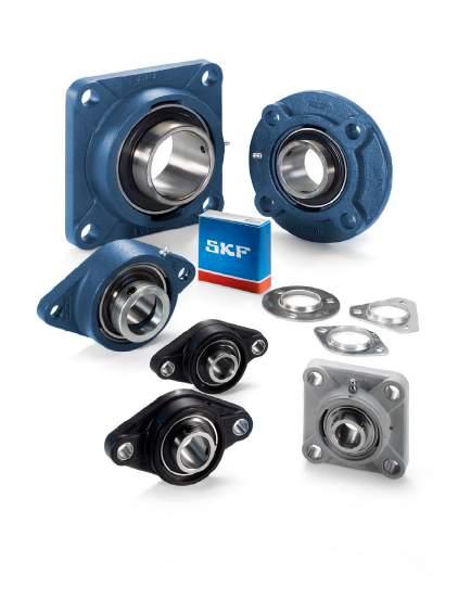
164
165 Flanged Y-bearing units Designs Flanged Y-TECH units Flanged Y-bearing units with a cast housing Flanged Y-bearing units with a pressed steel housing Data general Dimensions Tolerances Radial internal clearance Materials Load carrying ability of the housings Attaching to a support surface End covers Grease fills Mounting Product tables Flanged Y-TECH units with a housing with a square flange and grub screws, metric shafts Flanged Y-TECH units with a housing with an oval flange and grub screws, metric shafts Flanged Y-bearing units with a cast housing with a square flange and grub screws, metric shafts inch shafts Flanged Y-bearing units with a cast housing with a square flange and an eccentric locking collar, metric shafts inch shafts Flanged Y-bearing units with a cast housing with a square flange and an adapter sleeve, metric shafts inch shafts Flanged Y-bearing units with a cast housing with an oval flange and grub screws, metric shafts inch shafts Flanged Y-bearing units with a cast housing with an oval flange and an eccentric locking collar metric shafts inch shafts Flanged Y-bearing units with a cast housing with an oval flange and an adapter sleeve, metric shafts inch shafts Flanged Y-bearing units with a cast housing with a round flange and grub screws. metric shafts Flanged Y-bearing units with a pressed steel housing and grub screws, metric shafts inch shafts Flanged Y-bearing units with a pressed steel housing and an eccentric locking collar, metric shafts inch shafts
 grey cast iron ( fig.")
 They are located on the shaft via the inner ring of the insert bearing with either: grub (set) screws an eccentric locking collar an adapter sleeve The")

166 Flanged Y-bearing units Designs Fig. 1 SKF flanged Y-bearing units are available as standard in a wide variety of designs. The standard assortment includes flanged Y-bearing units with housings made of: composite material ( fig. 1) grey cast iron ( fig. 2) pressed sheet steel ( fig. 3) They are located on the shaft via the inner ring of the insert bearing with either: grub (set) screws an eccentric locking collar an adapter sleeve The Y-bearing can be sealed with either: Fig. 2 the standard integral seal the standard integral seal and an additional flinger the highly efficient multiple seal For additional information about Y-bearings, refer to the section Y-bearings, starting on page79. Flanged Y-bearing units available from stock are listed in the product tables. Other units can be assembled by ordering the parts separately. The tables on pages 168 to 169 show the wide variety of combinations of Y-bearings and flanged housings. Fig

 with a square flange and four bolt holes FYTBK series ( fig.")

167 Flanged Y-TECH units Fig. 4 Flanged Y-TECH units have housings made of composite material. They were developed for bearing arrangements that must operate reliably in difficult environments for extended periods without maintenance.there are two standard series available: FYK series ( fig. 4) with a square flange and four bolt holes FYTBK series ( fig. 5) with an oval flange and two bolt holes For additional information about Y-bearing units for the food industry, refer to page 274. Flanged Y-TECH units in the FYK series are fitted with Y-bearings in the: YAR 2-2F series, unit designation suffix TF YAR 2-2RF series, unit designation suffix TR These units, which are attached to the shaft with grub screws, are in the standard SKF assortment. Fig


168 Flanged Y-bearing units Fig. 6 Flanged Y-bearing units with a cast housing Flanged Y-bearing units with a cast housing can be relubricated through a grease fitting in the housing. This makes them especially suitable for bearing arrangements that operate under any of the following conditions: high levels of contamination high speeds high temperatures relatively heavy loads Three different housing designs are available: Fig. 7 FY and FYJ series with a square flange and four holes for attachment bolts ( fig. 6) FYC series with a round flange and four holes for attachment bolts ( fig. 7) FYT, FYTB and FYTJ series with an oval flange and two holes for attachment bolts ( fig. 8). Fig

 PFD series with a triangular flange and three square holes for attachment bolts ( fig. 10) PFT series with an oval flange and two square holes for attachment bolts ( fig.")
169 Flanged Y-bearing units with a pressed steel housing Flanged Y-bearing units with a pressed steel housing are designed for simple applications with limited loads and speeds. The two-part housing, which has no provision for relubrication, is ordered separately from the insert bearing, making a large number of combinations possible. The flanged housings made of pressed steel are available in three different series: PF series with a round flange and three or four square holes for attachment bolts ( fig. 9) PFD series with a triangular flange and three square holes for attachment bolts ( fig. 10) PFT series with an oval flange and two square holes for attachment bolts ( fig. 11) Fig. 9 Fig Fig
170 Flanged Y-bearing units Flanged Y-bearing unit Housings of composite material Cast housings Y-bearings FYK 5(00) FYTBK 5(00) FY 5(00) FYJ 5(00) FYM 5(00) FYT 5(00) YAR 2-2F FYK.. TF FYTBK.. TF FY.. TF FYJ.. TF FYM.. TF 3/4 1 1 /2 in. 1) 3/4 1 1 /4 in. 1) 1/ /16 in. 3/4 2 1 /2 in. 1) 1 7 /16 3 in mm mm mm mm FYT.. TF 1/2 2 3 /16 in. YAR 2-2RF FYK.. TR FYTBK.. TR FY.. TR 3/4 1 1 /2 in. 1) 3/4 1 1 /4 in. 1) 3/4 2 1 /2 in. 1) 3/4 2 1 /2 in. 1) mm mm mm mm 1) YAR 2-2RF/HV mm 1) mm 1) mm 1) mm 1) 3/4 1 1 /2 in. 1) 3/4 1 7 /16 in. 1) 3/4 1 1 /2 in. 1) 3/4 1 1 /2 in. 1) YAR 2-2RF/ VE mm 1) mm 1) mm 1) mm 1) YAT mm 1) mm 1) mm 1) mm 1) FYT.. RM 1/2 2 3 /16 in. YEL 2-2F mm 1) mm 1) mm FY.. WF /16 in mm 1) YEL 2-2RF/ VL mm 1) mm 1) mm 1) mm 1) YET 2 1 /2 /16 3/4 2 3 /16 in mm 1) 3/4 1 in. 1) mm 1) 3/4 1 in. 1) FY.. FM mm mm 1) 3/4 1 1 /2 in. 1) FYT.. FM 1/2 2 3 /16 in. YSA 2-2FK on adapter sleeve 1 /4 /16 /8 3/4 2 3 /8 in mm 1) 3/4 1 in. 1) mm 1) 3/4 1 in. 1) mm 1) 3/4 2 in. 1) FYJ.. KF mm 17262(00) mm 1) mm 1) mm 1) mm 1) 1) Parts must be ordered separately. 168
171 Flanged Y-bearing unit Cast housings Pressed steel housings Y-bearings FYTB 5(00) FYTJ 5(00) FYC 5(00) PF PFD PFT YAR 2-2F FYTB.. TF mm 3/4 1 3 /4 in. FYTJ.. TF FYC.. TF 3/4 1 3 /4 in. 3/4 2 1 /2 in. 1) 3/4 1 3 /4 in. 1) 3/4 1 1 /2 in. 1) 3/4 1 1 /2 in. 1) mm mm mm 1) mm 1) mm 1) YAR 2-2RF FYTB.. TR mm mm 1) mm 1) mm 1) mm 1) mm 1) 3/4 1 3 /4 in. 1) 3/4 1 3 /4 in. 1) 3/4 2 1 /2 in. 1) 3/4 1 3 /4 in. 1) 3/4 1 1 /2 in. 1) 3/4 1 1 /2 in. 1) YAR 2-2RF/HV mm 1) mm 1) mm 1) mm 1) mm 1) mm 1) 3/4 1 1 /2 in. 1) 3/4 1 1 /2 in. 1) 3/4 1 1 /2 in. 1) 3/4 1 1 /2 in. 1) 3/4 1 1 /2 in. 1) 3/4 1 1 /2 in. 1) YAR 2-2RF/ VE mm 1) mm 1) mm 1) mm 1) mm 1) mm 1) 4 YAT mm 1) mm 1) mm 1) mm 1) 5/ /16 in. 1) mm 1) 5/8 1 1 /2 in. 1) mm 1) 5/8 1 1 /2 in. 1) YEL 2-2F FYTB.. WF mm mm 1) mm 1) mm 1) 1/ /16 in. 1) mm 1/2 1 1 /2 in. 1) mm 1/2 1 1 /2 in. 1) YEL 2-2RF/ VL mm 1) mm 1) mm 1) mm 1) mm 1) mm 1) YET 2 FYTB.. FM mm mm 1) mm 1) mm 1) mm 1) mm 1) 3/4 1 1 /2 in. 1) 3/4 1 1 /2 in. 1) 3/4 1 1 /2 in. 1) 3/4 1 3 /4 in. 1) 3/4 1 1 /2 in. 1) 3/4 1 1 /2 in. 1) YSA 2-2FK on adapter sleeve 3 /4 /4 /8 /4 /4 3/4 1 3 /4 in. 1) mm 1) 3/4 1 in. 1) FYTJ.. KF mm 3/4 1 in mm 1) 3/4 2 in. 1) mm 1) 3/4 1 3 in. 1) mm 1) 3/4 1 1 in. 1) mm 1) 17262(00) mm 1) mm 1) mm 1) mm 1) mm 1) mm 1) 1) Parts must be ordered separately. 169
172 Flanged Y-bearing units Data general Dimensions The boundary dimensions for most flanged Y-bearing housings are in accordance with the following standards: Housings in the FY, FYT and FYTB series are in accordance with ISO 3228:1993. Housings in the FYJ, FYTJ and FYC series are in accordance with JIS B Housings in the PF, PFD and PFT series are in accordance with ISO 3228:1993. T Fig. 12 Tolerances For flanged Y-bearing units with a cast housing, the tolerance for the total width T of the unit ( fig. 12) is: ±0,5 mm for units up to and including 50 mm bore diameter ±0,6 mm for larger units For flanged Y-bearing units with housings made of composite material or grey cast iron, the outside diameter of the bearing is matched to the diameter of the housing bore so that the outer ring is prevented from turning in its seat, but still able to compensate for misalignment. Additional information about tolerances for the inner ring bore are listed in the section Y-bearings on page 89. Radial internal clearance The Y-bearing used in a flanged Y-bearing unit has the same radial internal clearance as a similarly sized individual Y-bearing. Additional information about the radial internal clearance can be found in the section Y-bearings on page 90. Materials Composite housings These housings are made of injection moulded glass fibre reinforced polyamide 6. A steel coil embedded in the housing adds greater stability to the form of the housing, even if temperatures are elevated. The bolt holes for housings in the FYK and FYTBK series are reinforced with zinc-plated sheet steel inserts. The standard housing colour is black. Cast housings Cast housings are manufactured from grey cast iron EN-GJL HB195 in accordance with EN 1561:1997. Pressed steel housings Pressed steel housings are made from cold-rolled steel and are zinc-coated for corrosion protection. Load carrying ability of the housings Housings made of either composite material or grey cast iron are able to withstand the same dynamic and static loads as the Y-bearings they incorporate. These Y-bearing units can also be used for applications where shock loads or variable axial loads occur. If SKF Y-bearing units are to be used in an application where health, safety, or the environment is at risk, contact the SKF application engineering service during the design phase. 170
173 Pressed steel housings have a lower load carrying capacity than their insert bearings. Permissible radial loads are specified in the product tables. The axial load should not exceed 20% of the permissible radial load. If the Y-bearing units will be subjected to shock loads or variable axial loads, a grey cast iron or Y-TECH housing should always be used. Flanged composite housings and most grey cast iron housings have a recess ( fig. 13a), or shoulder ( fig. 13b) at the back for accurate positioning, either on an appropriate shoulder or in a bore in the machine wall. An appropriate shoulder can be provided by one of the following methods: H11 D a Fig. 13 machining the wall accordingly ( fig. 13c) attaching an appropriate washer to the wall by several screws ( fig. 13d) Furthermore, these features relieve the attachment bolts of radial forces. a 4 Attaching to a support surface Flanged Y-bearing units have two, three or four bolt holes through which they can be attached to their support surface with threaded fasteners. These bolt holes are: D a h8 round and reinforced with pressed steel inserts in composite housings drilled and round in cast housings square in pressed steel housings In the absence of a centring shoulder and when heavy loads apply, SKF recommends doweling the housing to its support surface. Dimples for the dowel pin holes are cast into housings in the FY, FYJ, FYTB and FYTJ series. Information on the position and size of the holes for these dowel pins is provided in table 1. b c d 171
174 Flanged Y-bearing units Table 1 Position and size of dowel pin holes for flanged Y-bearing housings made of grey cast iron J 7 N 4 J 7 N 4 J 6 J 6 Housing Dimensions for housings in the size FY, FYJ series FYT, FYTB, FYTJ series J 6 J 7 N 4 J 6 J 7 N 4 mm , , , , , , , , , ,
175 End covers To protect the shaft ends and avoid any accidents, end covers are available for flanged Y-TECH units and most flanged Y-bearing units with a cast housing ( fig. 14). In the product tables, end covers in the ECY 2 series are shown together with the appropriate bearing unit. The designation of the end cover is listed together with the distance that the end cover protrudes from the housing. For additional information about end covers, refer to the section Design of Y-bearing arrangements, on page 47. Fig. 14 Grease fills All standard SKF flanged Y-bearing units are filled with a high-quality long-lasting grease containing a lithium-calcium thickener that has a consistency of 2 on the NLGI scale. For additional information about lubricants and lubrication, refer to the section Lubrication and maintenance, starting on page Mounting The procedure for mounting a flanged Y-bearing unit depends on: the design of the housing the method used to attach the unit to the shaft These methods are described in detail in the section Mounting instructions, starting on page
176 Flanged Y-TECH units with a housing with a square flange and grub screws, metric shafts d mm A 1 N 3,2 H14 d s 1 B D a H11 TF T A 2 G TR J L Dimensions Basic load Fatigue Limiting Designation ratings load speed Bearing unit dynamic static limit with shaft d A 1 A 2 B D a J L N G s 1 T C C 0 P u tolerance h6 mm kn kn r/min ,3 63, ,3 37,3 12,7 6,55 0, FYK 20 TF ,3 63, ,3 37,3 12,7 6,55 0, FYK 20 TR ,1 74, ,8 38,8 14 7,8 0, FYK 25 TF ,1 74, ,8 38,8 14 7,8 0, FYK 25 TR ,3 38,1 93,7 82, ,2 42,2 19,5 11,2 0, FYK 30 TF 33 15,3 38,1 93,7 82, ,2 42,2 19,5 11,2 0, FYK 30 TR ,9 106, , ,4 46,4 25,5 15,3 0, FYK 35 TF ,9 106, , ,4 46,4 25,5 15,3 0, FYK 35 TR ,2 115,9 101, , ,2 54,2 30,7 19 0, FYK 40 TF ,2 115,9 101, , ,2 54,2 30,7 19 0, FYK 40 TR 174
177 A 5 Designations Mass Appropriate end cover Bearing unit Separate components Bearing Designation Dimension Housing Bearing unit A kg mm FYK 20 TF FYK 504 YAR 204-2F 0,26 ECY ,5 FYK 20 TR FYK 504 YAR 204-2RF 0,26 ECY ,5 FYK 25 TF FYK 505 YAR 205-2F 0,33 ECY FYK 25 TR FYK 505 YAR 205-2RF 0,33 ECY FYK 30 TF FYK 506 YAR 206-2F 0,48 ECY FYK 30 TR FYK 506 YAR 206-2RF 0,48 ECY FYK 35 TF FYK 507 YAR 207-2F 0,66 ECY FYK 35 TR FYK 507 YAR 207-2RF 0,66 ECY FYK 40 TF FYK 508 YAR 208-2F 0,87 ECY ,5 FYK 40 TR FYK 508 YAR 208-2RF 0,87 ECY ,5 175
178 Flanged Y-TECH units with a housing with an oval flange and grub screws, metric shafts d mm A 1 N 3,2 H14 d s 1 B D a H11 J H G A 2 L TF T TR Dimensions Basic load Fatigue Limiting Designation ratings load speed Bearing unit dynamic static limit with shaft d A 1 A 2 B D a H J L N G s 1 T C C 0 P u tolerance h6 mm kn kn r/min 20 29, , , ,3 37,3 12,7 6,55 0, FYTBK 20 TF 29, , , ,3 37,3 12,7 6,55 0, FYTBK 20 TR ,1 63, ,8 38,8 14 7,8 0, FYTBK 25 TF ,1 63, ,8 38,8 14 7,8 0, FYTBK 25 TR ,1 76,2 142,5 116, ,2 42,2 19,5 11,2 0, FYTBK 30 TF ,1 76,2 142,5 116, ,2 42,2 19,5 11,2 0, FYTBK 30 TR ,9 88, , ,4 46,4 25,5 15,3 0, FYTBK 35 TF ,9 88, , ,4 46,4 25,5 15,3 0, FYTBK 35 TR 176
179 A 5 Designations Mass Appropriate end cover Bearing unit Separate components Bearing Designation Dimension Housing Bearing unit A kg mm FYTBK 20 TF FYTBK 504 YAR 204-2F 0,24 ECY ,5 FYTBK 20 TR FYTBK 504 YAR 204-2RF 0,24 ECY ,5 FYTBK 25 TF FYTBK 505 YAR 205-2F 0,29 ECY FYTBK 25 TR FYTBK 505 YAR 205-2RF 0,29 ECY FYTBK 30 TF FYTBK 506 YAR 206-2F 0,44 ECY FYTBK 30 TR FYTBK 506 YAR 206-2RF 0,44 ECY FYTBK 35 TF FYTBK 507 YAR 207-2F 0,61 ECY FYTBK 35 TR FYTBK 507 YAR 207-2RF 0,61 ECY
180 Flanged Y-bearing units with a cast housing with a square flange and grub screws, metric shafts d mm A 1 A 2 N 3,2 H14 d s 1 B D a H11 TF G T TR J L Dimensions Basic load Fatigue Limiting Designation ratings load speed Bearing unit dynamic static limit with shaft d A 1 A 2 B D a J L N G s 1 T C C 0 P u tolerance h6 mm kn kn r/min ,4 55, , ,9 32,9 9,56 4,75 0, FY 12 TF ,4 55, , ,9 32,9 9,56 4,75 0, FY 15 TF ,4 55, , ,9 32,9 9,56 4,75 0, FY 17 TF 20 29, ,3 63, , ,3 37,3 12,7 6,55 0, FY 20 TF 25, , ,3 33,3 12,7 6,55 0, FYJ 20 TF 29, ,3 63, , ,3 37,3 12,7 6,55 0, FY 20 TR ,1 74, , ,8 38,8 14 7,8 0, FY 25 TF ,1 74, ,8 35,8 14 7,8 0, FYJ 25 TF ,1 74, , ,8 38,8 14 7,8 0, FY 25 TR 30 32, ,1 93,7 82, , ,2 42,2 19,5 11,2 0, FY 30 TF ,1 93, ,2 40,2 19,5 11,2 0, FYJ 30 TF 32, ,1 93,7 82, , ,2 42,2 19,5 11,2 0, FY 30 TR 35 34, ,9 106, ,4 46,4 25,5 15,3 0, FY 35 TF ,9 106, ,4 44,4 25,5 15,3 0, FYJ 35 TF 34, ,9 106, ,4 46,4 25,5 15,3 0, FY 35 TR 40 38, ,2 115,9 101, ,2 54,2 30,7 19 0, FY 40 TF ,2 115, ,2 51,2 30,7 19 0, FYJ 40 TF 38, ,2 115,9 101, ,2 54,2 30,7 19 0, FY 40 TR ,2 119, ,2 54,2 33,2 21,6 0, FY 45 TF ,2 119, ,2 52,2 33,2 21,6 0, FYJ 45 TF ,2 119, ,2 54,2 33,2 21,6 0, FY 45 TR ,6 125, ,6 60,6 35,1 23,2 0, FY 50 TF ,6 125, ,6 54,6 35,1 23,2 0, FYJ 50 TF ,6 125, ,6 60,6 35,1 23,2 0, FY 50 TR 55 47, ,6 150, ,4 64,4 43,6 29 1, FY 55 TF ,6 150, ,4 58,4 43,6 29 1, FYJ 55 TF 47, ,6 150, ,4 64,4 43,6 29 1, FY 55 TR ,1 161, ,7 73,7 52,7 36 1, FY 60 TF ,1 161, ,7 68,7 52,7 36 1, FYJ 60 TF ,1 161, ,7 73,7 52,7 36 1, FY 60 TR 178
181 A 5 Designations Mass Appropriate end cover Bearing unit Separate components Bearing Designation Dimension Housing Bearing unit A kg mm FY 12 TF FY 503 M YAR 203/12-2F 0,47 FY 15 TF FY 503 M YAR 203/15-2F 0,45 FY 17 TF FY 503 M YAR 203-2F 0,44 FY 20 TF FY 504 M YAR 204-2F 0,60 ECY ,5 FYJ 20 TF FYJ 504 YAR 204-2F 0,65 FY 20 TR FY 504 M YAR 204-2RF 0,60 ECY ,5 FY 25 TF FY 505 M YAR 205-2F 0,77 ECY FYJ 25 TF FYJ 505 YAR 205-2F 0,86 FY 25 TR FY 505 M YAR 205-2RF 0,77 ECY FY 30 TF FY 506 M YAR 206-2F 1,10 ECY FYJ 30 TF FYJ 506 YAR 206-2F 1,20 FY 30 TR FY 506 M YAR 206-2RF 1,10 ECY FY 35 TF FY 507 M YAR 207-2F 1,40 ECY FYJ 35 TF FYJ 507 YAR 207-2F 1,50 FY 35 TR FY 507 M YAR 207-2RF 1,40 ECY FY 40 TF FY 508 M YAR 208-2F 1,90 ECY ,5 FYJ 40 TF FYJ 508 YAR 208-2F 1,80 FY 40 TR FY 508 M YAR 208-2RF 1,90 ECY ,5 FY 45 TF FY 509 M YAR 209-2F 2,10 ECY FYJ 45 TF FYJ 509 YAR 209-2F 2,45 FY 45 TR FY 509 M YAR 209-2RF 2,10 ECY FY 50 TF FY 510 M YAR 210-2F 2,50 ECY ,5 FYJ 50 TF FYJ 510 YAR 210-2F 3,15 FY 50 TR FY 510 M YAR 210-2RF 2,50 ECY ,5 FY 55 TF FY 511 M YAR 211-2F 3,60 ECY FYJ 55 TF FYJ 511 YAR 211-2F 3,45 FY 55 TR FY 511 M YAR 211-2RF 3,60 ECY FY 60 TF FY 512 M YAR 212-2F 4,60 ECY ,5 FYJ 60 TF FYJ 512 YAR 212-2F 4,50 FY 60 TR FY 512 M YAR 212-2RF 4,60 ECY ,5 179
182 Flanged Y-bearing units with a cast housing with a square flange and grub screws, metric shafts d mm A 1 A 2 N 3,2 H14 d s 1 B D a H11 TF G T J L Dimensions Basic load Fatigue Limiting Designation ratings load speed Bearing unit dynamic static limit with shaft d A 1 A 2 B D a J L N G s 1 T C C 0 P u tolerance h6 mm kn kn r/min 65 52, ,3 161,9 149, ,9 76,9 57,2 40 1, FY 65 TF ,3 161, ,9 72,9 57,2 40 1, FYJ 65 TF 70 50,3 21,3 69,9 161, ,7 70,7 62,4 44 1, FYJ 70 TF 75 53,6 22,1 73,1 179, ,1 80,1 66,3 49 2, FYJ 75 TF 80 54, ,9 179, ,7 81,7 72,8 53 2, FYJ 80 TF 90 63,4 23, , ,6 72 2, FYJ 90 TF ,4 215, ,4 107, , FYJ 100 TF 180
183 A 5 Designations Mass Appropriate end cover Bearing unit Separate components Bearing Designation Dimension Housing Bearing unit A kg mm FY 65 TF FY 513 M YAR 213-2F 5,30 ECY ,5 FYJ 65 TF FYJ 513 YAR 213-2F 5,80 FYJ 70 TF FYJ 514 YAR 214-2F 6,00 FYJ 75 TF FYJ 515 YAR 215-2F 6,80 FYJ 80 TF FYJ 516 YAR 216-2F 7,60 FYJ 90 TF FYJ 518 YAR 218-2F 11,5 FYJ 100 TF FYJ 520 YAR 220-2F 15,2 181
184 Flanged Y-bearing units with a cast housing with a square flange and grub screws, inch shafts d 1 /2 1 1 /4 in A 1 A 2 d s 1 B TF G T J L Dimensions d A 1 A 2 B J L G s 1 T Designation Bearing unit in/mm 1/ / FY 1/2 TF 12,7 23,4 9,9 27, , ,9 30,6 5/ / FY 5/8 TF 15,875 23,4 9,9 27, , ,9 30,6 3/ / FY 3/4 TF 19,05 29, , ,3 37, / FYJ 3/4 TF 25, ,3 33,3 13/ / FY 13/16 TF 20, , ,8 38,8 7/ / FY 7/8 TF 22, , ,8 38,8 15/ / FY 15/16 TF 23, , ,8 38, / FY 1. TF 25, , ,8 38, / FYJ 1. TF , ,8 35,8 1 1 / / FY 1.1/16 TF 26, , ,1 82, ,2 42,2 1 1 / / FY 1.1/8 TF 28,575 32, ,1 82, ,2 42,2 1 3 / / FY 1.3/16 TF 30,163 32, ,1 82, ,2 42,2 1 1 / / FY 1.1/4 TF 31,75 34, , ,4 46, / FYJ 1.1/4 TF , ,4 44,4 182
185 Designations Basic load Fatigue Limiting Mass Bearing unit Separate components ratings load speed Bearing unit Housing Bearing dynamic static limit with shaft C C 0 P u tolerance h6 4.3 lbf/kn lbf/kn r/min lb/kg FY 1/2 TF FY 503 U YAR F ,56 4,75 0,2 0,46 FY 5/8 TF FY 503 U YAR F ,56 4,75 0, FY 3/4 TF FY 504 M YAR F ,7 6,55 0,28 0,61 FYJ 3/4 TF FYJ 504 YAR F ,7 6,55 0,28 0,66 FY 13/16 TF FY 505 U YAR F ,8 0,335 0,81 FY 7/8 TF FY 505 U YAR F ,8 0,335 0,80 FY 15/16 TF FY 505 U YAR F ,8 0,335 0,78 FY 1. TF FY 505 M YAR F ,8 0,335 0,77 FYJ 1. TF FYJ 505 YAR F ,8 0,335 0,86 FY 1.1/16 TF FY 506 U YAR F ,5 11,2 0,475 1,10 FY 1.1/8 TF FY 506 U YAR F ,5 11,2 0,475 1,10 FY 1.3/16 TF FY 506 U YAR F ,5 11,2 0,475 1,10 FY 1.1/4 TF FY 507 M YAR F ,5 15,3 0,655 1,45 FYJ 1.1/4 TF FYJ 507 YAR F ,5 15,3 0,655 1,55 183
186 Flanged Y-bearing units with a cast housing with a square flange and grub screws, inch shafts d 1 5 / /16 in A 1 A 2 d s 1 B G T FY.. TF FY.. RM J L Dimensions d A 1 A 2 B J L G s 1 T Designation Bearing unit in/mm 1 5 / / FY 1.5/16 TF 33,338 34, , ,4 46,4 1 3 / / FY 1.3/8 TF 34,925 34, , ,4 46,4 1 7 / / FY 1.7/16 TF 36,513 34, , ,4 46, / FYM 1.7/16 TF 38, ,2 101, ,2 54,2 1 1 / / FY 1.1/2 TF 38,1 38, ,2 101, ,2 54, / FYJ 1.1/2 TF , ,2 51, / FYM 1.1/2 TF , ,2 54,2 1 5 / / FY 1.5/8 TF 41, , ,2 54, / / FYM 1.11/16 TF 42, , ,6 60,6 1 3 / / FY 1.3/4 TF 44, , ,2 54, / FY 1.3/4 RM , ,5 54, / FYJ 1.3/4 TF , ,2 52, / FYM 1.3/4 TF , ,6 60, / / FY 1.15/16 TF 49, , ,6 60, / FYM 1.15/16 TF 47, , ,4 64,4 184
187 Designations Basic load Fatigue Limiting Mass Bearing unit Separate components ratings load speed Bearing unit Housing Bearing dynamic static limit with shaft C C 0 P u tolerance h6 4.3 lbf/kn lbf/kn r/min lb/kg FY 1.5/16 TF FY 507 U YAR F ,5 15,3 0,655 1,45 FY 1.3/8 TF FY 507 U YAR F ,5 15,3 0,655 1,40 FY 1.7/16 TF FY 507 U YAR F ,5 15,3 0,655 1,40 FYM 1.7/16 TF FY 508 U YAR F ,7 19 0,8 2,00 FY 1.1/2 TF FY 508 M YAR F ,7 19 0,8 1,90 FYJ 1.1/2 TF FYJ 508 YAR F ,7 19 0,8 1,95 FYM 1.1/2 TF FY 509 U YAR F ,2 21,6 0,915 2,50 FY 1.5/8 TF FY 509 U YAR F ,2 21,6 0,915 2,20 FYM 1.11/16 TF FY 510 U YAR F ,50 FY 1.3/4 TF FY 509 M YAR F ,2 21,6 0,915 2,15 FY 1.3/4 RM FY 509 U YAT ,2 21,6 0,915 2,00 FYJ 1.3/4 TF FYJ 509 YAR F ,2 21,6 0,915 2,50 FYM 1.3/4 TF FY 510 U YAR F ,1 23,2 0,98 2,50 FY 1.15/16 TF FY 510 U YAR F ,1 23,2 0,98 2,50 FYM 1.15/16 TF FY 511 U YAR F ,6 29 1,25 4,00 185
188 Flanged Y-bearing units with a cast housing with a square flange and grub screws, inch shafts d 2 3 in A 1 A 2 d s 1 B G T J L Dimensions d A 1 A 2 B J L G s 1 T Designation Bearing unit in/mm / FY 2. TF 50,8 47, , ,4 64, / FYJ 2. TF , ,4 58,4 2 3 / / FY 2.3/16 TF 55,563 47, ,4 64, / FYM 2.3/16 TF , ,7 73,7 2 1 / / FY 2.1/4 TF 57, , ,7 73,7 2 7 / / FY 2.7/16 TF 61, , ,7 73, / FYM 2.7/16 TF 57,15 17,5 69,6 149,3 187, ,7 76,2 2 1 / / FY 2.1/2 TF 63,5 52, ,3 149, ,9 76, / FYJ 2.1/2 TF , ,9 72, / / FY 2.11/16 TF 68,263 52,5 16,5 68,3 149, ,9 72,4 2 3 / / FY 2.3/4 TF 69,85 65, ,1 152, ,1 87, / / FY 2.15/16 TF 74,613 65, ,1 152, , / FYM 2.15/16 TF 58,7 22,2 77,9 152, ,7 82, / FYM 3. TF 76,2 58,7 22,2 77,9 152, ,7 82,6 186
189 Designations Basic load Fatigue Limiting Mass Bearing unit Separate components ratings load speed Bearing unit Housing Bearing dynamic static limit with shaft C C 0 P u tolerance h6 4.3 lbf/kn lbf/kn r/min lb/kg FY 2. TF FY 511 M YAR F ,6 29 1,25 3,75 FYJ 2. TF FYJ 511 YAR F ,6 29 1,25 3,60 FY 2.3/16 TF FY 511 U YAR F ,6 29 1,25 3,55 FYM 2.3/16 TF FY 512 U YAR F ,7 36 1,53 5,00 FY 2.1/4 TF FY 512 U YAR F ,7 36 1,53 4,75 FY 2.7/16 TF FY 512 U YAR F ,7 36 1,53 4,60 FYM 2.7/16 TF FY 514 U YAR F ,4 44 1,86 6,0 FY 2.1/2 TF FY 513 M YAR F ,2 40 1,7 5,40 FYJ 2.1/2 TF FYJ 513 YAR F ,2 40 1,7 5,90 FY 2.11/16 TF FY 513 U YAR F ,2 40 1,7 5,10 FY 2.3/4 TF FY 515 U YAR F ,3 49 2,04 6,10 FY 2.15/16 TF FY 515 U YAR F ,3 49 2,04 8,15 FYM 2.15/16 TF FY 516 U YAR F ,8 53 2,16 8,00 FYM 3. TF FY 516 U YAR F ,8 53 2,16 8,00 187
190 Flanged Y-bearing units with a cast housing with a square flange and an eccentric locking collar, metric shafts d mm A 1 A 2 N 3,2 H14 d s 1 B 1 D a H11 G FM T WF J L Dimensions Basic load Fatigue Limiting Designation ratings load speed Bearing unit dynamic static limit with shaft d A 1 A 2 B 1 D a J L N G s 1 T C C 0 P u tolerance h6 mm kn kn r/min ,6 55, , ,1 39,1 9,56 4,75 0, FY 15 FM ,6 55, , ,1 39,1 9,56 4,75 0, FY 17 FM 20 29, ,3 63, , ,5 42,5 12,7 6,55 0, FY 20 FM 29, ,7 68,3 63, , ,6 45,6 12,7 6,55 0, FY 20 WF , , ,5 42,5 14 7,8 0, FY 25 FM ,4 74, , ,9 45,6 14 7,8 0, FY 25 WF 30 32, ,7 93,7 82, , ,7 46,7 19,5 11,2 0, FY 30 FM 32, ,4 93,7 82, , ,1 50,1 19,5 11,2 0, FY 30 WF 35 34, ,9 106, ,4 50,4 25,5 15,3 0, FY 35 FM 34, ,1 106, ,3 53,3 25,5 15,3 0, FY 35 WF 40 38, ,7 115,9 101, ,7 56,7 30,7 19 0, FY 40 FM 38, ,3 115,9 101, ,9 58,9 30,7 19 0, FY 40 WF ,7 119, ,7 56,7 33,2 21,6 0, FY 45 FM ,3 119, ,9 58,9 33,2 21,6 0, FY 45 WF ,7 125, ,7 60,7 35,1 23,2 0, FY 50 FM ,7 125, ,1 66,1 35,1 23,2 0, FY 50 WF 55 47, ,4 150, ,4 67,4 43,6 29 1, FY 55 FM 47, ,4 150, ,6 74,6 43,6 29 1, FY 55 WF ,1 161, ,6 73,6 52,7 36 1, FY 60 FM ,8 161, ,8 80,8 52,7 36 1, FY 60 WF 188
191 A 5 Designations Mass Appropriate end cover Bearing unit Separate components Bearing Designation Dimension Housing Bearing unit A kg mm FY 15 FM FY 503 M YET 203/15 0,47 FY 17 FM FY 503 M YET 203 0,48 FY 20 FM FY 504 M YET 204 0,62 ECY ,5 FY 20 WF FY 504 M YEL 204-2F 0,65 ECY ,5 FY 25 FM FY 505 M YET 205 0,78 ECY FY 25 WF FY 505 M YEL 205-2F 0,83 ECY FY 30 FM FY 506 M YET 206 1,10 ECY FY 30 WF FY 506 M YEL 206-2F 1,20 ECY FY 35 FM FY 507 M YET 207 1,50 ECY FY 35 WF FY 507 M YEL 207-2F 1,55 ECY FY 40 FM FY 508 M YET 208 1,95 ECY ,5 FY 40 WF FY 508 M YEL 208-2F 2,05 ECY ,5 FY 45 FM FY 509 M YET 209 2,15 ECY FY 45 WF FY 509 M YEL 209-2F 2,25 ECY FY 50 FM FY 510 M YET 210 2,55 ECY ,5 FY 50 WF FY 510 M YEL 210-2F 2,70 ECY ,5 FY 55 FM FY 511 M YET 211 3,60 ECY FY 55 WF FY 511 M YEL 211-2F 3,85 ECY FY 60 FM FY 512 M YET 212 4,70 ECY ,5 FY 60 WF FY 512 M YEL 212-2F 5,00 ECY ,5 189
192 Flanged Y-bearing units with a cast housing with a square flange and an eccentric locking collar, inch shafts d 5 /8 1 3 /4 in A 1 A 2 d s 1 B 1 G FM T WF J L Dimensions d A 1 A 2 B 1 J L G s 1 T Designation Bearing unit in/mm 5/ / FY 5/8 FM 15,875 23,4 9,9 28, , ,1 36,8 3/ / FY 3/4 FM 19,05 29, , ,5 42,5 7/ / FY 7/8 FM 22, ,5 42, / FY 1. FM 25, ,5 42, / FY 1. WF , ,9 45,9 1 1 / / FY 1.1/8 FM 28,575 32, ,7 82, ,7 46,7 1 3 / / FY 1.3/16 FM 30,163 32, ,7 82, ,7 46,7 1 1 / / FY 1.1/4 FM 31,75 34, , ,4 50, / FY 1.1/4 WF 34, , ,3 53,3 1 3 / / FY 1.3/8 FM 34,925 34, , ,4 50,4 1 7 / / FY 1.7/16 FM 36,513 34, , ,4 50,4 1 1 / / FY 1.1/2 FM 38,1 38, ,7 101, ,7 56, / FY 1.1/2 WF 38, ,3 101, ,9 58, / / FY 1.11/16 FM 42, , ,7 56,5 1 3 / / FY 1.3/4 FM 44, , ,7 56,5 190
193 Designations Basic load Fatigue Limiting Mass Bearing unit Separate components ratings load speed Bearing Housing Bearing dynamic static limit with shaft unit C C 0 P u tolerance h6 4.4 lbf/kn lbf/kn r/min lb/kg FY 5/8 FM FY 503 U YET ,56 4,75 0,2 0,47 FY 3/4 FM FY 504 U YET ,7 6,55 0,28 0,63 FY 7/8 FM FY 505 U YET ,8 0,335 0,81 FY 1. FM FY 505 U YET ,8 0,335 0,78 FY 1. WF FY 505 U YEL F ,8 0,335 0,82 FY 1.1/8 FM FY 506 U YET ,5 11,2 0,475 1,10 FY 1.3/16 FM FY 506 U YET ,5 11,2 0,475 1,10 FY 1.1/4 FM FY 507 U YET ,5 15,3 0,655 1,55 FY 1.1/4 WF FY 507 U YEL F ,5 15,3 0,655 1,60 FY 1.3/8 FM FY 507 U YET ,5 15,3 0,655 1,50 FY 1.7/16 FM FY 507 U YET ,5 15,3 0,655 1,45 FY 1.1/2 FM FY 508 U YET ,7 19 0,8 2,00 FY 1.1/2 WF FY 508 U YEL F ,7 19 0,8 2,10 FY 1.11/16 FM FY 509 U YET ,2 21,6 0,915 2,20 FY 1.3/4 FM FY 509 U YET ,2 21,6 0,915 2,15 191
194 Flanged Y-bearing units with a cast housing with a square flange and an eccentric locking collar, inch shafts d 1 15 / /16 in A 1 A 2 d s 1 B 1 G FM T WF J L Dimensions d A 1 A 2 B 1 J L G s 1 T Designation Bearing unit in/mm 1 15 / / FY 1.15/16 FM 49, , ,7 60, / FY 1.15/16 WF , ,1 66, / FY 2. FM 50,8 47, , ,4 67,4 2 3 / / FY 2.3/16 FM 55,563 47, , ,4 67, / FY 2.3/16 WF 47, , ,6 74,6 2 7 / / FY 2.7/16 WF 61, , ,8 80,8 192
195 Designations Basic load Fatigue Limiting Mass Bearing unit Separate components ratings load speed Bearing Housing Bearing dynamic static limit with shaft unit C C 0 P u tolerance h6 4.4 lbf/kn lbf/kn r/min lb/kg FY 1.15/16 FM FY 510 U YET ,1 23,2 0,98 2,55 FY 1.15/16 WF FY 510 U YEL F ,1 23,2 0,98 2,75 FY 2. FM FY 511 U YET ,6 29 1,25 3,75 FY 2.3/16 FM FY 511 U YET ,00 43,6 29 1,25 3,65 FY 2.3/16 WF FY 511 U YEL F ,6 29 1,25 3,85 FY 2.7/16 WF FY 512 U YEL F ,7 36 1,53 5,05 193
196 Flanged Y-bearing units with a cast housing with a square flange and an adapter sleeve, metric shafts d mm A 1 N 3,2 H14 d s 1 B 1 D a H11 G T A 2 J L Dimensions Basic load Fatigue Designations 1) ratings load Bearing Adapter dynamic static limit unit sleeve d A 1 A 2 B 1 D a J L N G s 1 T C C 0 P u mm kn kn , ,8 0,335 FYJ 25 KF H , ,5 11,2 0,475 FYJ 30 KF H , ,3 43,3 25,5 15,3 0,655 FYJ 35 KF H , ,7 19 0,8 FYJ 40 KF H , ,5 50,5 33,2 21,6 0,915 FYJ 45 KF H , ,5 52,5 35,1 23,2 0,98 FYJ 50 KF H , ,5 57,5 43,6 29 1,25 FYJ 55 KF H , ,3 63,3 52,7 36 1,53 FYJ 60 KF H , ,8 65,8 57,2 40 1,7 FYJ 65 KF H ) Bearing unit and adapter sleeve to be ordered separately 194
197 Designations Limiting Mass Bearing unit Separate components speed Bearing unit without of the bearing unit + sleeve adapter sleeve Housing Bearing 4.5 r/min kg FYJ 25 KF FYJ 505 YSA 205-2FK ,73 FYJ 30 KF FYJ 506 YSA 206-2FK ,05 FYJ 35 KF FYJ 507 YSA 207-2FK ,35 FYJ 40 KF FYJ 508 YSA 208-2FK ,75 FYJ 45 KF FYJ 509 YSA 209-2FK ,10 FYJ 50 KF FYJ 510 YSA 210-2FK ,80 FYJ 55 KF FYJ 511 YSA 211-2FK ,60 FYJ 60 KF FYJ 512 YSA 212-2FK ,60 FYJ 65 KF FYJ 513 YSA 213-2FK ,00 195
198 Flanged Y-bearing units with a cast housing with a square flange and an adapter sleeve, inch shafts d 3 /4 2 1 /8 in A 1 N 3,2 H14 d s 1 B 1 D a H11 G T A 2 J L Dimensions Designations 1) Bearing Adapter unit sleeve d A 1 A 2 B 1 D a J L N G s 1 T in/mm 3/ / FYJ 25 KF HE , , / / FYJ 30 KF HA , , / FYJ 30 KF HE , , / / FYJ 35 KF HA , , ,3 43,3 1 1 / / FYJ 40 KF HE , , / / FYJ 45 KF HA , , ,5 50,5 1 1 / / FYJ 45 KF HE , , ,5 50,5 1 5 / / FYJ 50 KF HS , , ,5 52, / / FYJ 50 KF HA , , ,5 52,5 1 3 / / FYJ 50 KF HE , , ,5 52, / / FYJ 55 KF HA , , ,5 57, / FYJ 55 KF HE 2311 B 50, , ,5 57,5 2 1 / / FYJ 60 KF HS , , ,3 63,3 1) Bearing unit and adapter sleeve to be ordered separately 196
199 Designations Basic load Fatigue Limiting Mass Bearing unit Separate components ratings load speed Bearing unit without Housing Bearing dynamic static limit + sleeve adapter sleeve C C 0 P u 4.5 lbf/kn lbf/kn r/min lb/kg FYJ 25 KF FYJ 505 YSA 205-2FK ,8 0,335 0,73 FYJ 30 KF FYJ 506 YSA 206-2FK ,5 11,2 0,475 1,05 FYJ 30 KF FYJ 506 YSA 206-2FK ,5 11,2 0,475 1,05 FYJ 35 KF FYJ 507 YSA 207-2FK ,5 15,3 0,655 1,35 FYJ 40 KF FYJ 508 YSA 208-2FK ,7 19 0,8 1,75 FYJ 45 KF FYJ 509 YSA 209-2FK ,2 21,6 0,915 2,15 FYJ 45 KF FYJ 509 YSA 209-2FK ,2 21,6 0,915 2,10 FYJ 50 KF FYJ 510 YSA 210-2FK ,1 23,2 0,98 2,85 FYJ 50 KF FYJ 510 YSA 210-2FK ,1 23,2 0,98 2,85 FYJ 50 KF FYJ 510 YSA 210-2FK ,1 23,2 0,98 2,80 FYJ 55 KF FYJ 511 YSA 211-2FK ,6 29 1,25 3,60 FYJ 55 KF FYJ 511 YSA 211-2FK ,6 29 1,25 3,60 FYJ 60 KF FYJ 512 YSA 212-2FK ,7 36 1,53 4,60 197
200 Flanged Y-bearing units with a cast housing with a square flange and an adapter sleeve, inch shafts d 2 3 / /8 in A 1 N 3,2 H14 d s 1 B 1 D a H11 G T A 2 J L Dimensions Designations 1) Bearing Adapter unit sleeve d A 1 A 2 B 1 D a J L N G s 1 T in/mm 2 3 / / FYJ 65 KF HA , , ,8 65,8 2 1 / / FYJ 65 KF HE , , ,8 65,8 2 3 / / FYJ 65 KF HS , , ,8 65,8 1) Bearing unit and adapter sleeve to be ordered separately 198
201 Designations Basic load Fatigue Limiting Mass Bearing unit Separate components ratings load speed Bearing unit without Housing Bearing dynamic static limit + sleeve adapter sleeve C C 0 P u 4.5 lbf/kn lbf/kn r/min lb/kg FYJ 65 KF FYJ 513 YSA 213-2FK ,2 40 1,7 6,20 FYJ 65 KF FYJ 513 YSA 213-2FK ,2 40 1,7 6,10 FYJ 65 KF FYJ 513 YSA 213-2FK ,2 40 1,7 6,00 199
202 Flanged Y-bearing units with a cast housing with an oval flange and grub screws, metric shafts d mm A 1 A 2 N 3,2 H14 d s 1 B D a H11 J H G TF T TR L Dimensions Basic load Fatigue Limiting Designation ratings load speed Bearing unit dynamic static limit with shaft d A 1 A 2 B D a H J L N G s 1 T C C 0 P u tolerance h6 mm kn kn r/min ,4 50,8 98,5 76, , ,9 32,9 9,56 4,75 0, FYTB 12 TF ,4 50,8 98,5 76, , ,9 32,9 9,56 4,75 0, FYTB 15 TF ,4 50,8 98,5 76, , ,9 32,9 9,56 4,75 0, FYTB 17 TF 20 29, , ,5 11, ,3 37,3 12,7 6,55 0, FYTB 20 TF 25, , ,3 33,3 12,7 6,55 0, FYTJ 20 TF 29, , ,5 11, ,3 37,3 12,7 6,55 0, FYTB 20 TR ,1 63, , ,8 38,8 14 7,8 0, FYTB 25 TF ,1 63, ,8 35,8 14 7,8 0, FYTJ 25 TF ,1 63, , ,8 38,8 14 7,8 0, FYTB 25 TR 30 32, ,1 76,2 141,5 116, , ,2 42,2 19,5 11,2 0, FYTB 30 TF 30,5 13,5 38,1 76, ,2 40,2 19,5 11,2 0, FYTJ 30 TF 32, ,1 76,2 141,5 116, , ,2 42,2 19,5 11,2 0, FYTB 30 TR 35 34, ,9 88, ,4 46,4 25,5 15,3 0, FYTB 35 TF ,9 88, ,4 44,4 25,5 15,3 0, FYTJ 35 TF 34, ,9 88, ,4 46,4 25,5 15,3 0, FYTB 35 TR 40 38, ,2 88,9 171,5 143, ,2 54,2 30,7 19 0, FYTB 40 TF ,2 88, ,2 51,2 30,7 19 0, FYTJ 40 TF 38, ,2 88,9 171,5 143, ,2 54,2 30,7 19 0, FYTB 40 TR ,2 98,4 178,5 148, ,2 54,2 33,2 21,6 0, FYTB 45 TF ,2 98, ,2 52,2 33,2 21,6 0, FYTJ 45 TF ,2 98,4 178,5 148, ,2 54,2 33,2 21,6 0, FYTB 45 TR ,6 101, ,6 60,6 35,1 23,2 0, FYTB 50 TF ,6 101, ,6 54,6 35,1 23,2 0, FYTJ 50 TF ,6 101, ,6 60,6 35,1 23,2 0, FYTB 50 TR 200
203 A 5 Designations Mass Appropriate end cover Bearing unit Separate components Bearing Designation Dimension Housing Bearing unit A kg mm FYTB 12 TF FYTB 503 M YAR 203/12-2F 0,42 FYTB 15 TF FYTB 503 M YAR 203/15-2F 0,40 FYTB 17 TF FYTB 503 M YAR 203-2F 0,39 FYTB 20 TF FYTB 504 M YAR 204-2F 0,50 ECY ,5 FYTJ 20 TF FYTJ 504 YAR 204-2F 0,43 FYTB 20 TR FYTB 504 M YAR 204-2RF 0,50 ECY ,5 FYTB 25 TF FYTB 505 M YAR 205-2F 0,63 ECY FYTJ 25 TF FYTJ 505 YAR 205-2F 0,58 FYTB 25 TR FYTB 505 M YAR 205-2RF 0,63 ECY FYTB 30 TF FYTB 506 M YAR 206-2F 0,93 ECY FYTJ 30 TF FYTJ 506 YAR 206-2F 0,93 FYTB 30 TR FYTB 506 M YAR 206-2RF 0,93 ECY FYTB 35 TF FYTB 507 M YAR 207-2F 1,25 ECY FYTJ 35 TF FYTJ 507 YAR 207-2F 1,15 FYTB 35 TR FYTB 507 M YAR 207-2RF 1,25 ECY FYTB 40 TF FYTB 508 M YAR 208-2F 1,65 ECY ,5 FYTJ 40 TF FYTJ 508 YAR 208-2F 1,55 FYTB 40 TR FYTB 508 M YAR 208-2RF 1,65 ECY ,5 FYTB 45 TF FYTB 509 M YAR 209-2F 1,80 ECY FYTJ 45 TF FYTJ 509 YAR 209-2F 2,20 FYTB 45 TR FYTB 509 M YAR 209-2RF 1,80 ECY FYTB 50 TF FYTB 510 M YAR 210-2F 2,15 ECY ,5 FYTJ 50 TF FYTJ 510 YAR 210-2F 3,10 FYTB 50 TR FYTB 510 M YAR 210-2RF 2,15 ECY ,5 201
204 Flanged Y-bearing units with a cast housing with an oval flange and grub screws, inch shafts d 1 /2 1 1 /8 in A 1 A 2 N d s 1 B J H G TF T RM L Dimensions d A 1 A 2 B H J L N G s 1 T Designation Bearing unit in/mm 1/ / FYT 1/2 RM 12,7 23,4 11,5 22,5 98,5 76, , , / FYT 1/2 TF 23,4 11,5 27,4 98,5 76, , ,9 30,6 5/ / FYT 5/8 RM 15,875 23,4 11,5 22,5 98,5 76, , , / FYT 5/8 TF 23,4 11,5 27,4 98,5 76, , ,9 30,6 3/ / FYT 3/4 RM 19,05 24,6 11,1 25,5 111,9 89,7 60,5 11, ,3 32, / FYT 3/4 TF/AH 24,6 11, ,9 89,7 60,5 11, ,3 32, / FYTB 3/4 TF 29, ,5 11, ,3 37, / FYTJ 3/4 TF 25, ,3 33,3 7/ / FYT 7/8 TF 22, , , , ,8 38,8 15/ / FYT 15/16 RM 23, , , , ,5 38, / FYT 15/16 TF , , , ,8 38, / FYT 1. RM 25, , , , ,5 38, / FYT 1. TF , , , ,8 38, / FYTB 1. TF , , ,8 38, / FYTJ 1. TF , ,8 35,8 1 1 / / FYT 1.1/8 TF 28,575 32, ,1 141,5 116, , ,2 42,2 202
205 Designations Basic load Fatigue Limiting Mass Bearing unit Separate components ratings load speed Bearing Housing Bearing dynamic static limit with shaft unit C C 0 P u tolerance h6 4.6 lbs/kn lbs/kn r/min lb/kg FYT 1/2 RM FYT 503 U YAT ,56 4,75 0,2 0,31 FYT 1/2 TF FYT 503 U YAR F ,56 4,75 0,2 0,33 FYT 5/8 RM FYT 503 U YAT ,56 4,75 0,2 0,30 FYT 5/8 TF FYT 503 U YAR F ,56 4,75 0,2 0,31 FYT 3/4 RM FYT 504 U YAT ,7 6,55 0,28 0,47 FYT 3/4 TF/AH FYT 504 U/AH YAR F/AH ,7 6,55 0,28 0,50 FYTB 3/4 TF FYTB 504 M YAR F ,7 6,55 0,28 0,50 FYTJ 3/4 TF FYTJ 504 YAR F ,7 6,55 0,28 0,43 FYT 7/8 TF FYT 505 U YAR F ,8 0,335 0,66 FYT 15/16 RM FYT 505 U YAT ,8 0,335 0,61 FYT 15/16 TF FYT 505 U YAR F ,8 0,335 0,64 FYT 1. RM FYT 505 U YAT ,8 0,335 0,60 FYT 1. TF FYT 505 U YAR F ,8 0,335 0,60 FYTB 1. TF FYTB 505 M YAR F ,8 0,335 0,63 FYTJ 1. TF FYTJ 505 YAR F ,8 0,335 0,58 FYT 1.1/8 TF FYT 506 U YAR F ,5 11,2 0,475 0,95 203
206 Flanged Y-bearing units with a cast housing with an oval flange and grub screws, inch shafts d 1 3 / /16 in A 1 A 2 N d s 1 B J H G TF T RM L Dimensions d A 1 A 2 B H J L N G s 1 T Designation Bearing unit in/mm 1 3 / / FYT 1.3/16 RM 30,163 32, ,5 116, , , / FYT 1.3/16 TF 32, ,1 141,5 116, , ,2 42,2 1 1 / / FYT 1.1/4 RM 31,75 34, , , ,5 46, / FYTB 1.1/4 TF 34, , ,4 46, / FYTJ 1.1/4 TF , ,4 44,4 1 5 / / FYT 1.5/16 TF 33,338 34, , , , ,4 46,4 1 3 / / FYT 1.3/8 RM 34,925 34, , , ,5 46, / FYT 1.3/8 TF 34, , , , ,4 46,4 1 7 / / FYT 1.7/16 RM 36,513 34, , , ,5 46, / FYT 1.7/16 TF 34, , , , ,4 46,4 1 1 / / FYT 1.1/2 RM 38,1 38, ,5 143, , ,5 52, / FYT 1.1/2 TF 38, ,2 171,5 143, , ,2 54, / FYTB 1.1/2 TF 38, ,2 171,5 143, ,2 54, / FYTJ 1.1/2 TF , ,2 51,2 1 5 / / FYT 1.5/8 TF 41, ,2 178,5 148, , ,2 54, / / FYT 1.11/16 RM 42, ,5 178,5 148, , ,5 54, / FYT 1.11/16 TF ,2 178,5 148, , ,2 54,2 204
207 Designations Basic load Fatigue Limiting Mass Bearing unit Separate components ratings load speed Bearing Housing Bearing dynamic static limit with shaft unit C C 0 P u tolerance h6 4.6 lbs/kn lbs/kn r/min lb/kg FYT 1.3/16 RM FYT 506 U YAT ,5 11,2 0,475 0,88 FYT 1.3/16 TF FYT 506 U YAR F ,5 11,2 0,475 0,93 FYT 1.1/4 RM FYT 507 U YAT ,5 15,3 0,655 1,21 FYTB 1.1/4 TF FYTB 507 U YAR F ,5 15,3 0,655 1,40 FYTJ 1.1/4 TF FYTJ 507 U YAR F ,5 15,3 0,655 1,30 FYT 1.5/16 TF FYT 507 U YAR F ,5 15,3 0,655 1,30 FYT 1.3/8 RM FYT 507 U YAT ,5 15,3 0,655 1,15 FYT 1.3/8 TF FYT 507 U YAR F ,5 15,3 0,655 1,27 FYT 1.7/16 RM FYT 507 U YAT ,5 15,3 0,655 1,14 FYT 1.7/16 TF FYT 507 U YAR F ,5 15,3 0,655 1,25 FYT 1.1/2 RM FYT 508 U YAT ,7 19 0,8 1,60 FYT 1.1/2 TF FYT 508 U YAR F ,7 19 0,8 1,70 FYTB 1.1/2 TF FYTB 508 M YAR F ,7 19 0,8 1,70 FYTJ 1.1/2 TF FYTJ 508 YAR F ,7 19 0,8 1,60 FYT 1.5/8 TF FYT 509 U YAR F ,2 21,6 0,915 1,90 FYT 1.11/16 RM FYT 509 U YAT ,2 21,6 0,915 1,74 FYT 1.11/16 TF FYT 509 U YAR F ,2 21,6 0,915 1,86 205
208 Flanged Y-bearing units with a cast housing with an oval flange and grub screws, inch shafts d 1 3 /4 2 3 /16 in A 1 A 2 N d s 1 B J H G TF T RM L Dimensions d A 1 A 2 B H J L N G s 1 T Designation Bearing unit in/mm 1 3 / / FYT 1.3/4 RM 44, ,5 178,5 148, , ,5 54, / FYT 1.3/4 TF ,2 178,5 148, , ,2 54, / FYTB 1.3/4 TF ,2 178,5 148, ,2 54, / FYTJ 1.3/4 TF , ,2 52, / / FYT 1.15/16 RM 49, , , , / FYT 1.15/16 TF , , , ,6 60, / FYT 2. RM 50,8 47,6 20, , ,5 62, / FYT 2. TF 47,6 20,6 55, , ,4 62,8 2 3 / / FYT 2.3/16 RM 55,563 47,6 20, , ,5 62, / FYT 2.3/16 TF 47,6 20,6 55, , ,4 62,8 206
209 Designations Basic load Fatigue Limiting Mass Bearing unit Separate components ratings load speed Bearing Housing Bearing dynamic static limit with shaft unit C C 0 P u tolerance h6 4.6 lbs/kn lbs/kn r/min lb/kg FYT 1.3/4 RM FYT 509 U YAT ,2 21,6 0,915 1,70 FYT 1.3/4 TF FYT 509 U YAR F ,2 21,6 0,915 1,80 FYTB 1.3/4 TF FYTB 509 M YAR F ,2 21,6 0,915 1,80 FYTJ 1.3/4 TF FYTJ 509 YAR F ,2 21,6 0,915 2,20 FYT 1.15/16 RM FYT 510 U YAT ,1 23,2 0,98 2,10 FYT 1.15/16 TF FYT 510 U YAR F ,1 23,2 0,98 2,25 FYT 2. RM FYT 511 U YAT ,6 29 1,25 3,30 FYT 2. TF FYT 511 U YAR F ,6 29 1,25 3,45 FYT 2.3/16 RM FYT 511 U YAT ,6 29 1,25 3,10 FYT 2.3/16 TF FYT 511 U YAR F ,6 29 1,25 3,25 207
210 Flanged Y-bearing units with a cast housing with an oval flange and an eccentric locking collar, metric shafts d mm A 1 A 2 N 3,2 H14 d s 1 B 1 D a H11 J H G FM T WF L Dimensions Basic load Fatigue Limiting Designation ratings load speed Bearing dynamic static limit with shaft unit d A 1 A 2 B 1 D a H J L N G s 1 T C C 0 P u tolerance h6 mm kn kn r/min ,6 50,8 98,5 76, , ,1 39,1 9,56 4,75 0, FYTB 15 FM ,6 50,8 98,5 76, , ,1 39,1 9,56 4,75 0, FYTB 17 FM 20 29, , ,5 11, ,5 42,5 12,7 6,55 0, FYTB 20 FM 29, ,7 50, ,5 11, ,6 45,6 12,7 6,55 0, FYTB 20 WF , , ,5 42,5 14 7,8 0, FYTB 25 FM ,4 63, , ,9 45,9 14 7,8 0, FYTB 25 WF 30 32, ,7 76,2 141,5 116, , ,7 46,7 19,5 11,2 0, FYTB 30 FM 32, ,4 76,2 141,5 116, , ,1 50,1 19,5 11,2 0, FYTB 30 WF 35 34, ,9 88, ,4 50,4 25,5 15,3 0, FYTB 35 FM 34, ,1 88, ,3 53,3 25,5 15,3 0, FYTB 35 WF 40 38, ,7 88,9 171,5 143, ,7 56,7 30,7 19 0, FYTB 40 FM 38, ,3 88,9 171,5 143, ,9 58,9 30,7 19 0, FYTB 40 WF ,7 98,4 178,5 148, ,7 56,7 33,2 21,6 0, FYTB 45 FM ,3 98,4 178,5 148, ,9 58,9 33,2 21,6 0, FYTB 45 WF ,7 101, ,7 60,7 35,1 23,2 0, FYTB 50 FM ,7 101, ,1 66,1 35,1 23,2 0, FYTB 50 WF 208
211 A 5 Designations Mass Appropriate end cover Bearing unit Separate components Bearing Designation Dimension Housing Bearing unit A kg mm FYTB 15 FM FYTB 503 M YET 203/15 0,42 FYTB 17 FM FYTB 503 M YET 203 0,41 FYTB 20 FM FYTB 504 M YET 204 0,52 ECY ,5 FYTB 20 WF FYTB 504 M YEL 204-2F 0,55 ECY ,5 FYTB 25 FM FYTB 505 M YET 205 0,64 ECY FYTB 25 WF FYTB 505 M YEL 205-2F 0,69 ECY FYTB 30 FM FYTB 506 M YET 206 0,95 ECY FYTB 30 WF FYTB 506 M YEL 206-2F 1,00 ECY FYTB 35 FM FYTB 507 M YET 207 1,30 ECY FYTB 35 WF FYTB 507 M YEL 207-2F 1,40 ECY FYTB 40 FM FYTB 508 M YET 208 1,70 ECY ,5 FYTB 40 WF FYTB 508 M YEL 208-2F 1,80 ECY ,5 FYTB 45 FM FYTB 509 M YET 209 1,85 ECY FYTB 45 WF FYTB 509 M YEL 209-2F 1,95 ECY FYTB 50 FM FYTB 510 M YET 210 2,20 ECY ,5 FYTB 50 WF FYTB 510 M YEL 210-2F 2,35 ECY ,5 209
212 Flanged Y-bearing units with a cast housing with an oval flange and an eccentric locking collar, inch shafts d 1 / /16 in A 1 A 2 N d s 1 B 1 J H G T L Dimensions d A 1 A 2 B 1 H J L N G s 1 T Designation Bearing unit in/mm 1/ / FYT 1/2 FM 12,7 23,4 11,5 26,6 98,5 76, , ,1 36,8 5/ / FYT 5/8 FM 15,875 23,4 11,5 28,6 98,5 76, , ,1 36,8 3/ / FYT 3/4 FM 19,05 24,6 11, ,7 60,3 11, ,5 37,8 7/ / FYT 7/8 FM 22, , , ,5 42,5 15/ / FYT 15/16 FM 23, , , ,5 42, / FYT 1. FM 25, , , ,5 42,5 1 1 / / FYT 1.1/8 FM 28,575 32, ,7 141,5 116, , ,7 46,7 1 3 / / FYT 1.3/16 FM 30,163 32, ,7 141,5 116, , ,7 46,7 1 1 / / FYT 1.1/4 FM 31,75 34, , , , ,4 50,4 1 3 / / FYT 1.3/8 FM 34,925 34, , , , ,4 50,4 1 7 / / FYT 1.7/16 FM 36,513 34, , , , ,4 50,4 1 1 / / FYT 1.1/2 FM 38,1 38, ,7 171,5 143, , ,7 56,5 1 3 / / FYT 1.3/4 FM 44, ,7 178,5 148, , ,7 56, / / FYT 1.15/16 FM 49, , , , ,7 60,7 210
213 Designations Basic load Fatigue Limiting Mass Bearing unit Separate components ratings load speed Bearing Housing Bearing dynamic static limit with shaft unit C C 0 P u tolerance h6 4.7 lbf/kn lbf/kn r/min lb/kg FYT 1/2 FM FYT 503 U YET ,56 4,75 0,2 0,35 FYT 5/8 FM FYT 503 U YET ,56 4,75 0,2 0,34 FYT 3/4 FM FYT 504 U YET ,7 6,55 0,28 0,53 FYT 7/8 FM FYT 505 U YET ,8 0,335 0,67 FYT 15/16 FM FYT 505 U YET ,8 0,335 0,66 FYT 1. FM FYT 505 U YET ,8 0,335 0,64 FYT 1.1/8 FM FYT 506 U YET ,5 11,2 0,475 0,98 FYT 1.3/16 FM FYT 506 U YET ,5 11,2 0,475 0,97 FYT 1.1/4 FM FYT 507 U YET ,5 15,3 0,655 1,40 FYT 1.3/8 FM FYT 507 U YET ,5 15,3 0,655 1,35 FYT 1.7/16 FM FYT 507 U YET ,5 15,3 0,655 1,30 FYT 1.1/2 FM FYT 508 U YET ,7 19 0,8 1,75 FYT 1.3/4 FM FYT 509 U YET ,2 21,6 0,915 1,85 FYT 1.15/16 FM FYT 510 U YET ,1 23,2 0,
214 Flanged Y-bearing units with a cast housing with an oval flange and an eccentric locking collar, inch shafts d /16 in A 1 A 2 N d s 1 B 1 J H G T L Dimensions d A 1 A 2 B 1 H J L N G s 1 T Designation Bearing unit in/mm / FYT 2. FM 50,8 47,6 20,6 48, , , ,4 65,8 2 3 / / FYT 2.3/16 FM 55,563 47,6 20,6 48, , , ,4 65,8 212
215 Designations Basic load Fatigue Limiting Mass Bearing unit Separate components ratings load speed Bearing Housing Bearing dynamic static limit with shaft unit C C 0 P u tolerance h6 4.7 lbf/kn lbf/kn r/min lb/kg FYT 2. FM FYT 511 U YET ,6 29 1,25 3,45 FYT 2.3/16 FM FYT 511 U YET ,6 29 1,25 3,35 213
216 Flanged Y-bearing units with a cast housing with an oval flange and an adapter sleeve, metric shafts d mm A 1 N 3,2 H14 d s 1 B 1 D a H11 J H G T A 2 L Dimensions Basic load Fatigue Designations 1) ratings load Bearing Adapter dynamic static limit unit sleeve d A 1 A 2 B 1 D a H J L N G s 1 T C C 0 P u mm kn kn , ,8 0,335 FYTJ 25 KF H ,5 13, , ,5 11,2 0,475 FYTJ 30 KF H , ,3 43,3 25,5 15,3 0,655 FYTJ 35 KF H , ,7 19 0,8 FYTJ 40 KF H , ,5 50,5 33,2 21,6 0,915 FYTJ 45 KF H , ,5 52,5 35,1 23,2 0,98 FYTJ 50 KF H ) Bearing unit and adapter sleeve to be ordered separately 214
217 Designations Limiting Mass Bearing unit Separate components speed Bearing unit without of the bearing unit + sleeve adapter sleeve Housing Bearing 4.8 r/min kg FYTJ 25 KF FYTJ 505 YSA 205-2FK ,72 FYTJ 30 KF FYTJ 506 YSA 206-2FK ,83 FYTJ 35 KF FYTJ 507 YSA 207-2FK ,30 FYTJ 40 KF FYTJ 508 YSA 208-2FK ,65 FYTJ 45 KF FYTJ 509 YSA 209-2FK ,20 FYTJ 50 KF FYTJ 510 YSA 210-2FK ,55 215
218 Flanged Y-bearing units with a cast housing with an oval flange and an adapter sleeve, inch shafts d 3 /4 1 3 /4 in A 1 N 3,2 H14 d s 1 B 1 D a H11 J H G T A 2 L Dimensions Designations 1) Bearing Adapter unit sleeve d A 1 A 2 B 1 D a H J L N G s 1 T in/mm 3/ / FYTJ 25 KF HE , , / / FYTJ 30 KF HA ,813 30,5 13, , / FYTJ 30 KF HE ,4 30,5 13, , / / FYTJ 35 KF HA , , ,3 43,3 1 1 / / FYTJ 40 KF HE , , / / FYTJ 45 KF HA , , ,5 50,5 1 1 / / FYTJ 45 KF HE , , ,5 50,5 1 5 / / FYTJ 50 KF HS , , ,5 52, / / FYTJ 50 KF HA , , ,5 52,5 1 3 / / FYTJ 50 KF HE , , ,5 52,5 1) Bearing unit and adapter sleeve to be ordered separately 216
219 Designations Basic load Fatigue Limiting Mass Bearing unit Separate components ratings load speed Bearing unit without Housing Bearing dynamic static limit + sleeve adapter sleeve C C 0 P u 4.8 lbf/kn lbf/kn r/min lb/kg FYTJ 25 KF FYTJ 505 YSA 205-2FK ,8 0,335 0,72 FYTJ 30 KF FYTJ 506 YSA 206-2FK ,5 11,2 0,475 0,83 FYTJ 30 KF FYTJ 506 YSA 206-2FK ,5 11,2 0,475 0,83 FYTJ 35 KF FYTJ 507 YSA 207-2FK ,5 15,3 0,655 1,30 FYTJ 40 KF FYTJ 508 YSA 208-2FK ,7 19 0,8 1,65 FYTJ 45 KF FYTJ 509 YSA 209-2FK ,2 21,6 0,915 2,20 FYTJ 45 KF FYTJ 509 YSA 209-2FK ,2 21,6 0,915 2,20 FYTJ 50 KF FYTJ 510 YSA 210-2FK ,1 23,2 0,98 2,55 FYTJ 50 KF FYTJ 510 YSA 210-2FK ,1 23,2 0,98 2,55 FYTJ 50 KF FYTJ 510 YSA 210-2FK ,1 23,2 0,98 2,55 217
220 Flanged Y-bearing units with a cast housing with a round flange and grub screws, metric shafts d mm T N d s 1 B D a J L G A 2 A3 J 1 A 1 Dimesions Basic load Fatigue Limiting Designation ratings load speed Bearing dynamic static limit with shaft unit d A 1 A 2 A 3 B D a J J 1 L N G s 1 T C C 0 P u tolerance h8 h6 mm kn kn r/min 20 25, , ,3 28,3 12,7 6,55 0, FYC 20 TF , , ,8 29,8 14 7,8 0, FYC 25 TF , , ,2 32,2 19,5 11,2 0, FYC 30 TF , , ,4 36,4 25,5 15,3 0, FYC 35 TF , , ,2 41,2 30,7 19 0, FYC 40 TF , , ,2 40,2 33,2 21,6 0, FYC 45 TF , , ,6 42,6 35,1 23,2 0, FYC 50 TF , , ,4 46,4 43,6 29 1, FYC 55 TF , , ,7 56,7 52,7 36 1, FYC 60 TF , , ,9 58,9 55,9 40 1, FYC 65 TF 218
221 Designations Mass Bearing unit Separate components Bearing Housing Bearing unit 4.9 kg FYC 20 TF FYC 504 YAR 204-2F 0,70 FYC 25 TF FYC 505 YAR 205-2F 0,93 FYC 30 TF FYC 506 YAR 206-2F 1,35 FYC 35 TF FYC 507 YAR 207-2F 1,55 FYC 40 TF FYC 508 YAR 208-2F 2,00 FYC 45 TF FYC 509 YAR 209-2F 2,65 FYC 50 TF FYC 510 YAR 210-2F 2,80 FYC 55 TF FYC 511 YAR 211-2F 4,30 FYC 60 TF FYC 512 YAR 212-2F 4,90 FYC 65 TF FYC 513 YAR 213-2F 5,70 219
222 Flanged Y-bearing units with a pressed steel housing and grub screws, metric shafts d mm T A 2 d B D a J H G YAT A 1 YAR-2F YAR-2RF PF N Dimensions Basic load Fatigue Permissible Designation ratings load housing Bearing unit dynamic static limit load No order d A 1 A 2 B D a H H 1 /L J N G T C C 0 P u radial designation mm kn kn kn , ,1 6 17,9 9,56 4,75 0,2 2,5 PF 12 TF , ,1 6 17,9 9,56 4,75 0,2 2,5 PFD 12 TF , ,1 6 17,9 9,56 4,75 0,2 2,5 PFT 12 TF , ,1 6 17,9 9,56 4,75 0,2 2,5 PF 15 TF , ,1 6 17,9 9,56 4,75 0,2 2,5 PFD 15 TF , ,1 6 17,9 9,56 4,75 0,2 2,5 PFT 15 TF , ,1 6 17,9 9,56 4,75 0,2 2,5 PF 17 RM , ,1 6 17,9 9,56 4,75 0,2 2,5 PF 17 TF , ,1 6 17,9 9,56 4,75 0,2 2,5 PFD 17 RM , ,1 6 17,9 9,56 4,75 0,2 2,5 PFD 17 TF , ,1 6 17,9 9,56 4,75 0,2 2,5 PFT 17 RM , ,1 6 17,9 9,56 4,75 0,2 2,5 PFT 17 TF , ,5 8,7 8 20,3 12,7 6,55 0,28 3,3 PF 20 RM ,5 8,7 8 20,3 12,7 6,55 0,28 3,3 PF 20 TF ,5 8,7 8 20,3 12,7 6,55 0,28 3,3 PF 20 TR , ,5 8,7 8 20,3 12,7 6,55 0,28 3,3 PFD 20 RM ,5 8,7 8 20,3 12,7 6,55 0,28 3,3 PFD 20 TF ,5 8,7 8 20,3 12,7 6,55 0,28 3,3 PFD 20 TR , ,5 8,7 8 20,3 12,7 6,55 0,28 3,3 PFT 20 RM ,5 8,7 8 20,3 12,7 6,55 0,28 3,3 PFT 20 TF ,5 8,7 8 20,3 12,7 6,55 0,28 3,3 PFT 20 TR , ,7 8 21,5 14 7,8 0,335 3,6 PF 25 RM , ,7 8 21,8 14 7,8 0,335 3,6 PF 25 TF , ,7 8 21,8 14 7,8 0,335 3,6 PF 25 TR , ,7 8 21,5 14 7,8 0,335 3,6 PFD 25 RM , ,7 8 21,8 14 7,8 0,335 3,6 PFD 25 TF , ,7 8 21,8 14 7,8 0,335 3,6 PFD 25 TR , ,7 8 21,5 14 7,8 0,335 3,6 PFT 25 RM , ,7 8 21,8 14 7,8 0,335 3,6 PFT 25 TF , ,7 8 21,8 14 7,8 0,335 3,6 PFT 25 TR 220
223 N H 1 J H J H PFD N PFT L Designation Order designations Mass Bearing unit Housing Bearing Bearing No order unit designation 4.10 kg PF 12 TF PF 40 YAR 203/12-2F 0,26 PFD 12 TF PFD 40 YAR 203/12-2F 0,19 PFT 12 TF PFT 40 YAR 203/12-2F 0,19 PF 15 TF PF 40 YAR 203/15-2F 0,25 PFD 15 TF PFD 40 YAR 203/15-2F 0,18 PFT 15 TF PFT 40 YAR 203/15-2F 0,18 PF 17 RM PF 40 YAT 203 0,22 PF 17 TF PF 40 YAR 203-2F 0,24 PFD 17 RM PFD 40 YAT 203 0,16 PFD 17 TF PFD 40 YAR 203-2F 0,17 PFT 17 RM PFT 40 YAT 203 0,16 PFT 17 TF PFT 40 YAR 203-2F 0,17 PF 20 RM PF 47 YAT 204 0,29 PF 20 TF PF 47 YAR 204-2F 0,32 PF 20 TR PF 47 YAR 204-2RF 0,32 PFD 20 RM PFD 47 YAT 204 0,23 PFD 20 TF PFD 47 YAR 204-2F 0,26 PFD 20 TR PFD 47 YAR 204-2RF 0,26 PFT 20 RM PFT 47 YAT 204 0,20 PFT 20 TF PFT 47 YAR 204-2F 0,23 PFT 20 TR PFT 47 YAR 204-2RF 0,23 PF 25 RM PF 52 YAT 205 0,33 PF 25 TF PF 52 YAR 205-2F 0,36 PF 25 TR PF 52 YAR 205-2RF 0,36 PFD 25 RM PFD 52 YAT 205 0,30 PFD 25 TF PFD 52 YAR 205-2F 0,33 PFD 25 TR PFD 52 YAR 205-2RF 0,33 PFT 25 RM PFT 52 YAT 205 0,25 PFT 25 TF PFT 52 YAR 205-2F 0,28 PFT 25 TR PFT 52 YAR 205-2RF 0,28 221
224 Flanged Y-bearing units with a pressed steel housing and grub screws, metric shafts d mm T A 2 d B D a J H G YAT A 1 YAR-2F YAR-2RF PF 1) N Dimensions Basic load Fatigue Permissible Designation ratings load housing Bearing unit dynamic static limit load No order d A 1 A 2 B D a H H 1 /L J N G T C C 0 P u radial designation mm kn kn kn 30 2,5 9,5 30, ,5 10, ,5 19,5 11,2 0,475 5 PF 30 RM 2,5 9,5 38, ,5 10, ,7 19,5 11,2 0,475 5 PF 30 TF 2,5 9,5 38, ,5 10, ,7 19,5 11,2 0,475 5 PF 30 TR 2,5 9,5 30, ,5 10, ,5 19,5 11,2 0,475 5 PFD 30 RM 2,5 9,5 38, ,5 10, ,7 19,5 11,2 0,475 5 PFD 30 TF 2,5 9,5 38, ,5 10, ,7 19,5 11,2 0,475 5 PFD 30 TR 2,5 9,5 30, ,5 10, ,5 19,5 11,2 0,475 5 PFT 30 RM 2,5 9,5 38, ,5 10, ,7 19,5 11,2 0,475 5 PFT 30 TF 2,5 9,5 38, ,5 10, ,7 19,5 11,2 0,475 5 PFT 30 TR 35 2, ,8 25,5 15,3 0,655 6,5 PF 35 RM 2, , ,9 25,5 15,3 0,655 6,5 PF 35 TF 2, , ,9 25,5 15,3 0,655 6,5 PF 35 TR 2, ,8 25,5 15,3 0,655 6,5 PFD 35 RM 2, , ,9 25,5 15,3 0,655 6,5 PFD 35 TF 2, , ,9 25,5 15,3 0,655 6,5 PFD 35 TR 2, ,8 25,5 15,3 0,655 6,5 PFT 35 RM 2, , ,9 25,5 15,3 0,655 6,5 PFT 35 TF 2, , ,9 25,5 15,3 0,655 6,5 PFT 35 TR 40 3, , ,8 30,7 19 0,8 7,5 PF 40 RM 3, , , ,7 30,7 19 0,8 7,5 PF 40 TF 3, , , ,7 30,7 19 0,8 7,5 PF 40 TR 3, , ,8 30,7 19 0,8 7,5 PFD 40 RM 3, , , ,7 30,7 19 0,8 7,5 PFD 40 TF 3, , , ,7 30,7 19 0,8 7,5 PFD 40 TR 3, , ,8 30,7 19 0,8 7,5 PFT 40 RM 3, , , ,7 30,7 19 0,8 7,5 PFT 40 TF 3, , , ,7 30,7 19 0,8 7,5 PFT 40 TR 45 3,5 10, ,6 13, ,3 33,2 21,6 0,915 8,3 PF 45 RM 3,5 10,5 49, ,6 13, ,7 33,2 21,6 0,915 8,3 PF 45 TF 3,5 10,5 49, ,6 13, ,7 33,2 21,6 0,915 8,3 PF 45 TR , , ,6 35,1 23,2 0,98 9 PF 50 RM , , ,6 35,1 23,2 0,98 9 PF 50 TF , , ,6 35,1 23,2 0,98 9 PF 50 TR 1) Housings PF 80, PF 85 and PF 90 have four attachment bolt holes. 222
225 N H 1 J H J H PFD N PFT L Designation Order designations Mass Bearing unit Housing Bearing Bearing No order unit designation 4.10 kg PF 30 RM PF 62 YAT 206 0,53 PF 30 TF PF 62 YAR 206-2F 0,58 PF 30 TR PF 62 YAR 206-2RF 0,58 PFD 30 RM PFD 62 YAT 206 0,42 PFD 30 TF PFD 62 YAR 206-2F 0,47 PFD 30 TR PFD 62 YAR 206-2RF 0,47 PFT 30 RM PFT 62 YAT 206 0,41 PFT 30 TF PFT 62 YAR 206-2F 0,46 PFT 30 TR PFT 62 YAR 206-2RF 0,46 PF 35 RM PF 72 YAT 207 0,67 PF 35 TF PF 72 YAR 207-2F 0,77 PF 35 TR PF 72 YAR 207-2RF 0,77 PFD 35 RM PFD 72 YAT 207 0,54 PFD 35 TF PFD 72 YAR 207-2F 0,64 PFD 35 TR PFD 72 YAR 207-2RF 0,64 PFT 35 RM PFT 72 YAT 207 0,55 PFT 35 TF PFT 72 YAR 207-2F 0,65 PFT 35 TR PFT 72 YAR 207-2RF 0,65 PF 40 RM PF 80 YAT 208 1,20 PF 40 TF PF 80 YAR 208-2F 1,30 PF 40 TR PF 80 YAR 208-2RF 1,30 PFD 40 RM PFD 80 YAT 208 0,90 PFD 40 TF PFD 80 YAR 208-2F 1,00 PFD 40 TR PFD 80 YAR 208-2RF 1,00 PFT 40 RM PFT 80 YAT 208 0,78 PFT 40 TF PFT 80 YAR 208-2F 0,90 PFT 40 TR PFT 80 YAR 208-2RF 0,90 PF 45 RM PF 85 YAT 209 1,25 PF 45 TF PF 85 YAR 209-2F 1,35 PF 45 TR PF 85 YAR 209-2RF 1,35 PF 50 RM PF 90 YAT 210 1,40 PF 50 TF PF 90 YAR 210-2F 1,55 PF 50 TR PF 90 YAR 210-2RF 1,55 223
226 Flanged Y-bearing units with a pressed steel housing and grub screws, inch shafts d 5 /8 1 1 /4 in T A 2 d B D a J H G YAR-2F A 1 YAR-2RF PF N Dimensions Designation Bearing unit No order d A 1 A 2 B D a H H 1 /L J N G T designation in/mm 5/ / PF 5/8 TF 15, , ,1 6 17,9 3/ / PF 3/4 TF 19, ,5 8,7 8 20, / PF 3/4 TR ,5 8,7 8 20, / PFD 3/4 TF ,5 8,7 8 20, / PFD 3/4 TR ,5 8,7 8 20, / PFT 3/4 TF ,5 8,7 8 20, v 0.80 PFT 3/4 TR ,5 8,7 8 20, / PF 1. TF 25, , ,7 8 21, / PF 1. TR , ,7 8 21, / PFD 1. TF , ,7 8 21, / PFD 1. TR , ,7 8 21, / PFT 1. TF , ,7 8 21, / PFT 1. TR , ,7 8 21,8 1 1/ / PF 1.1/4 TF 31,75 2, , , / PF 1.1/4 TR 2, , , / PFD 1.1/4 TF 2, , , / PFD 1.1/4 TR 2, , , / PFT 1.1/4 TF 2, , , / PFT 1.1/4 TR 2, , ,9 224
227 N H 1 J H J H PFD N PFT L Designation Order designations Basic load Fatigue Permissible Mass Bearing unit Housing Bearing ratings load housing Bearing No order dynamic static limit load unit designation C C 0 P u radial 4.10 lbf/kn lbf/kn lbf/kn lb/kg PF 5/8 TF PF 40 YAR F ,56 4,75 0,2 2,5 0,22 PF 3/4 TF PF 47 YAR F ,7 6,55 0,28 3,3 0,30 PF 3/4 TR PF 47 YAR RF ,7 6,55 0,28 3,3 0,30 PFD 3/4 TF PFD 47 YAR F ,7 6,55 0,28 3,3 0,24 PFD 3/4 TR PFD 47 YAR RF ,7 6,55 0,28 3,3 0,24 PFT 3/4 TF PFT 47 YAR F ,7 6,55 0,28 3,3 0,24 PFT 3/4 TR PFT 47 YAR RF ,7 6,55 0,28 3,3 0,24 PF 1. TF PF 52 YAR F ,8 0,335 3,6 0,35 PF 1. TR PF 52 YAR RF ,8 0,335 3,6 0,35 PFD 1. TF PFD 52 YAR F ,8 0,335 3,6 0,29 PFD 1. TR PFD 52 YAR RF ,8 0,335 3,6 0,29 PFT 1. TF PFT 52 YAR F ,8 0,335 3,6 0,28 PFT 1. TR PFT 52 YAR RF ,8 0,335 3,6 0,28 PF 1.1/4 TF PF 72 YAR F ,5 15,3 0,655 6,5 0,83 PF 1.1/4 TR PF 72 YAR RF ,5 15,3 0,655 6,5 0,83 PFD 1.1/4 TF PFD 72 YAR F ,5 15,3 0,655 6,5 0,69 PFD 1.1/4 TR PFD 72 YAR RF ,5 15,3 0,655 6,5 0,69 PFT 1.1/4 TF PFT 72 YAR F ,5 15,3 0,655 6,5 0,69 PFT 1.1/4 TR PFT 72 YAR RF ,5 15,3 0,655 6,5 0,69 225
228 Flanged Y-bearing units with a pressed steel housing and grub screws, inch shafts d 1 1 /2 1 3 /4 in T A 2 d B D a J H G YAR-2F A 1 YAR-2RF PF N Dimensions Designation Bearing unit No order d A 1 A 2 B D a H H 1 /L J N G T designation in/mm 1 1 / / PF 1.1/2 TF 38,1 3, , , , / PF 1.1/2 TR 3, , , , / PFD 1.1/2 TF 3, , , , / PFD 1.1/2 TR 3, , , , / PFT 1.1/2 TF 3, , , , / PFT 1.1/2 TR 3, , , ,7 1 3 / / PF 1.3/4 TF 44,45 3,5 10,5 49, ,6 13, , / PF 1.3/4 TR 3,5 10,5 49, ,6 13, ,7 226
229 N H 1 J H J H PFD N PFT L Designation Order designations Basic load Fatigue Permissible Mass Bearing unit Housing Bearing ratings load housing Bearing No order dynamic static limit load unit designation C C 0 P u radial lbf/kn lbf/kn lbf/kn lb/kg PF 1.1/2 TF PF 80 YAR F ,7 19 0,8 7,5 0,81 PF 1.1/2 TR PF 80 YAR RF ,7 19 0,8 7,5 0,81 PFD 1.1/2 TF PFD 80 YAR F ,7 19 0,8 7,5 1,05 PFD 1.1/2 TR PFD 80 YAR RF ,7 19 0,8 7, PFT 1.1/2 TF PFT 80 YAR F ,7 19 0,8 7,5 0,95 PFT 1.1/2 TR PFT 80 YAR RF ,7 19 0,8 7,5 0,95 PF 1.3/4 TF PF 85 YAR F ,2 21,6 0,915 8,3 1,25 PF 1.3/4 TR PF 85 YAR RF ,2 21,6 0,915 8,3 1,25 227
230 Flanged Y-bearing units with a pressed steel housing and an eccentric locking collar, metric shafts d mm T A 2 d B 1 D a J H G A 1 YET YEL.. -2F PF N Dimensions Basic load Fatigue Permissible Designation ratings load housing Bearing unit dynamic static limit load No order d A 1 A 2 B 1 D a H H 1 /L J N G T C C 0 P u radial designation mm kn kn kn , ,1 6 24,1 9,56 4,75 0,2 2,5 PF 15 FM , ,1 6 24,1 9,56 4,75 0,2 2,5 PFD 15 FM , ,1 6 24,1 9,56 4,75 0,2 2,5 PFT 15 FM , ,1 6 24,1 9,56 4,75 0,2 2,5 PF 17 FM , ,1 6 24,1 9,56 4,75 0,2 2,5 PFD 17 FM , ,1 6 24,1 9,56 4,75 0,2 2,5 PFT 17 FM ,5 8,7 8 25,5 12,7 6,55 0,28 3,3 PF 20 FM , ,5 8,7 8 28,6 12,7 6,55 0,28 3,3 PF 20 WF ,5 8,7 8 25,5 12,7 6,55 0,28 3,3 PFD 20 FM , ,5 8,7 8 28,6 12,7 6,55 0,28 3,3 PFD 20 WF ,5 8,7 8 25,5 12,7 6,55 0,28 3,3 PFT 20 FM , ,5 8,7 8 28,6 12,7 6,55 0,28 3,3 PFT 20 WF ,7 8 25,5 14 7,8 0,335 3,6 PF 25 FM , ,7 8 28,9 14 7,8 0,335 3,6 PF 25 WF ,7 8 25,5 14 7,8 0,335 3,6 PFD 25 FM , ,7 8 28,9 14 7,8 0,335 3,6 PFD 25 WF ,7 8 25,5 14 7,8 0,335 3,6 PFT 25 FM , ,7 8 28,9 14 7,8 0,335 3,6 PFT 25 WF 30 2,5 9,5 35, ,5 10, ,2 19,5 11,2 0,475 5 PF 30 FM 2,5 9,5 48, ,5 10, ,6 19,5 11,2 0,475 5 PF 30 WF 2,5 9,5 35, ,5 10, ,2 19,5 11,2 0,475 5 PFD 30 FM 2,5 9,5 48, ,5 10, ,6 19,5 11,2 0,475 5 PFD 30 WF 2,5 9,5 35, ,5 10, ,2 19,5 11,2 0,475 5 PFT 30 FM 2,5 9,5 48, ,5 10, ,6 19,5 11,2 0,475 5 PFT 30 WF 35 2, , ,9 25,5 15,3 0,655 6,5 PF 35 FM 2, , ,8 25,5 15,3 0,655 6,5 PF 35 WF 2, , ,9 25,5 15,3 0,655 6,5 PFD 35 FM 2, , ,8 25,5 15,3 0,655 6,5 PFD 35 WF 2, , ,9 25,5 15,3 0,655 6,5 PFT 35 FM 2, , ,8 25,5 15,3 0,655 6,5 PFT 35 WF 228
231 N H 1 J H J H PFD N PFT L Designation Order designations Mass Bearing unit Housing Bearing Bearing No order unit designation 4.11 kg PF 15 FM PF 40 YET 203/15 0,24 PFD 15 FM PFD 40 YET 203/15 0,21 PFT 15 FM PFT 40 YET 203/15 0,21 PF 17 FM PF 40 YET 203 0,22 PFD 17 FM PFD 40 YET 203 0,20 PFT 17 FM PFT 40 YET 203 0,19 PF 20 FM PF 47 YET 204 0,30 PF 20 WF PF 47 YEL 204-2F 0,33 PFD 20 FM PFD 47 YET 204 0,26 PFD 20 WF PFD 47 YEL 204-2F 0,29 PFT 20 FM PFT 47 YET 204 0,25 PFT 20 WF PFT 47 YEL 204-2F 0,28 PF 25 FM PF 52 YET 205 0,35 PF 25 WF PF 52 YEL 205-2F 0,40 PFD 25 FM PFD 52 YET 205 0,30 PFD 25 WF PFD 52 YEL 205-2F 0,35 PFT 25 FM PFT 52 YET 205 0,29 PFT 25 WF PFT 52 YEL 205-2F 0,34 PF 30 FM PF 62 YET 206 0,56 PF 30 WF PF 62 YEL 206-2F 0,62 PFD 30 FM PFD 62 YET 206 0,48 PFD 30 WF PFD 62 YEL 206-2F 0,54 PFT 30 FM PFT 62 YET 206 0,46 PFT 30 WF PFT 62 YEL 206-2F 0,52 PF 35 FM PF 72 YET 207 0,70 PF 35 WF PF 72 YEL 207-2F 0,78 PFD 35 FM PFD 72 YET 207 0,66 PFD 35 WF PFD 72 YEL 207-2F 0,74 PFT 35 FM PFT 72 YET 207 0,72 PFT 35 WF PFT 72 YEL 207-2F 0,80 229
232 Flanged Y-bearing units with a pressed steel housing and an eccentric locking collar, metric shafts d mm T A 2 d B 1 D a J H G A 1 YET YEL.. -2F PF N Dimensions Basic load Fatigue Permissible Designation ratings load housing Bearing unit dynamic static limit load No order d A 1 A 2 B 1 D a H H 1 /L J N G T C C 0 P u radial designation mm kn kn kn 40 3, , , ,2 30,7 19 0,8 7,5 PF 40 FM 3, , , ,4 30,7 19 0,8 7,5 PF 40 WF 3, , , ,2 30,7 19 0,8 7,5 PFD 40 FM 3, , , ,4 30,7 19 0,8 7,5 PFD 40 WF 3, , , ,2 30,7 19 0,8 7,5 PFT 40 FM 3, , , ,4 30,7 19 0,8 7,5 PFT 40 WF 45 3,5 10,5 43, ,6 13, ,2 33,2 21,6 0,915 8,3 PF 45 FM 3,5 10,5 56, ,6 13, ,4 33,2 21,6 0,915 8,3 PF 45 WF , , ,7 35,1 23,2 0,98 9 PF 50 FM , , ,1 35,1 23,2 0,98 9 PF 50 WF 230
233 N H 1 J H J H PFD N PFT L Designation Order designations Mass Bearing unit Housing Bearing Bearing No order unit designation 4.11 kg PF 40 FM PF 80 YET 208 1,20 PF 40 WF PF 80 YEL 208-2F 1,30 PFD 40 FM PFD 80 YET 208 1,05 PFD 40 WF PFD 80 YEL 208-2F 1,15 PFT 40 FM PFT 80 YET 208 0,94 PFT 40 WF PFT 80 YEL 208-2F 1,00 PF 45 FM PF 85 YET 209 1,30 PF 45 WF PF 85 YEL 209-2F 1,40 PF 50 FM PF 90 YET 210 1,50 PF 50 WF PF 90 YEL 210-2F 1,65 231
234 Flanged Y-bearing units with a pressed steel housing and an eccentric locking collar, inch shafts d 3 /4 1 1 /2 in T A 2 d B 1 D a J H G A 1 PF 1) N Dimensions Designation Bearing unit No order d A 1 A 2 B 1 D a H H 1 /L J N G T designation in/mm 3/ / PF 3/4 FM 19, ,5 8,7 8 25, / PFD 3/4 FM ,5 8,7 8 25, / PFT 3/4 FM ,5 8,7 8 25, / PF 1. FM 25, ,7 8 25, / PFD 1. FM ,7 8 25, / PFT 1. FM ,7 8 25,5 1 1 / / PF 1.1/2 FM 38,1 3, , , , / PFD 1.1/2 FM 3, , , , / PFT 1.1/2 FM 3, , , ,2 1) Housing PF 80 has four attachment bolt holes. 232
235 N H 1 J H J H PFD N PFT L Designation Order designations Basic load Fatigue Permissible Mass Bearing unit Housing Bearing ratings load housing Bearing No order dynamic static limit load unit designation C C 0 P u radial 4.11 lbf/kn lbf/kn lbf/kn lb/kg PF 3/4 FM PF 47 YET ,7 6,55 0,28 3,3 0,31 PFD 3/4 FM PFD 47 YET ,7 6,55 0,28 3,3 0,27 PFT 3/4 FM PFT 47 YET ,7 6,55 0,28 3,3 0,26 PF 1. FM PF 52 YET ,8 0,335 3,6 0,35 PFD 1. FM PFD 52 YET ,8 0,335 3,6 0,35 PFT 1. FM PFT 52 YET ,8 0,335 3,6 0,29 PF 1.1/2 FM PF 80 YET ,7 19 0,8 7,5 1,25 PFD 1.1/2 FM PFD 80 YET ,7 19 0,8 7,5 1,05 PFT 1.1/2 FM PFT 80 YET ,7 19 0,8 7,5 0,98 233
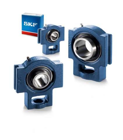
236
237 Y-bearing take-up units Designs Data general Dimensions Tolerances Radial internal clearance Materials Load carrying ability of the housings End covers Grease fills Mounting Product tables Y-bearing take-up units with a cast housing and grub screws, metric shafts inch shafts Y-bearing take-up units with a cast housing and an eccentric locking collar, metric shafts
238 Y-bearing take-up units Designs Fig. 1 Y-bearing take-up units consist of a cast housing and an insert bearing ( fig. 1). These units are typically mounted in take-up frames and connected by an adjustment screw. A grease fitting is provided in the housing for relubrication. Standard Y-bearing take-up units can be located on the shaft via the inner ring of the insert bearing with either: grub (set) screws an eccentric locking collar The Y-bearing is sealed with either: the standard integral seal the standard integral seal and an additional flinger Fig. 2 For additional information about Y-bearings, refer to the section Y-bearings, starting on page 79. Data general Dimensions The boundary dimensions of SKF Y-bearing take-up housings in the: H 1 TU series are in accordance with ISO 3228:1993 TUJ series are in accordance with JIS B A 1 Tolerances The tolerances ( fig.2), which are in accordance with ISO 3228:1993, are: ± 0,25 mm for the distance between the guide surfaces H 1 within the tolerance range H13 for the width of the guide surfaces A 1 Information about the tolerances of the inner ring bore diameter can be found in the section Y-bearings on page
239 Radial internal clearance The Y-bearing used in a Y-bearing take-up unit has the same radial internal clearance as a similarly sized individual Y-bearing. The values for radial internal clearance can be found in the section Y-bearings on page 90. Fig. 3 Materials The housings for Y-bearing take-up units are manufactured from grey cast iron EN-GJL HB195 in accordance with EN 1561:1997. Load carrying ability of the housings Cast housings can withstand the same dynamic and static loads as their insert bearings. Therefore, Y-bearing take-up units may also be used where shock loads or variable axial loads occur, provided the adjustment screw and the way it is secured to the Y-bearing take-up unit is sufficiently strong. If SKF Y-bearing units are to be used in an application where health, safety, or the environment is at risk, contact the SKF application engineering service during the design phase. End covers To protect the shaft ends and avoid any accidents, end covers are available for Y-bearing take-up units in the TU series ( fig. 3). In the product tables, end covers in the ECY 2 series are shown together with the appropriate bearing unit. The designation of the end cover is listed, together with the distance that the end cover protrudes from the housing. For additional information about end covers, refer to to the section Design of Y-bearing arrangements on page 47. Mounting The mounting procedures for a Y-bearing takeup unit depend on the method used to attach the unit to the shaft. The procedures are briefly described in the section Mounting instructions, starting on page Grease fills All standard SKF Y-bearing take-up units are filled with a high-quality, long-lasting grease containing a lithium-calcium thickener that has a consistency of 2 on the NLGI scale. For additional information about lubricants and lubrication, refer to the section Lubrication and maintenance starting on page
240 Y-bearing take-up units with a cast housing and grub screws, metric shafts d mm s 1 A 2 L 3 N 1 L 2 d B H H 1 D 1 N H 2 A 1 A L L 1 Dimensions Designation Bearing unit d A A 1 A 2 B D 1 H H 1 H 2 L L 1 L 2 L 3 N N 1 s 1 mm , ,3 TU 20 TF ,3 TUJ 20 TF , , ,8 TU 25 TF , ,8 TUJ 25 TF , , ,2 TU 30 TF , ,2 TUJ 30 TF , , ,4 TU 35 TF , ,4 TUJ 35 TF , , ,2 TU 40 TF , ,2 TUJ 40 TF , , ,2 TU 45 TF , ,2 TUJ 45 TF , , ,6 TU 50 TF , ,6 TUJ 50 TF , ,4 TU 55 TF , ,4 TUJ 55 TF , , ,7 TUJ 60 TF 238
241 A 5 Designations Basic load Fatigue Limiting Mass Appropriate end cover Bearing unit Separate components ratings load speed Bearing Designation Dimension Housing Bearing dynamic static limit with shaft unit C C 0 P u tolerance A 5 h6 kn kn r/min kg mm TU 20 TF TU 504 M YAR 204-2F 12,7 6,55 0, ,73 ECY ,5 TUJ 20 TF TUJ 504 YAR 204-2F 12,7 6,55 0, ,76 TU 25 TF TU 505 M YAR 205-2F 14 7,8 0, ,77 ECY TUJ 25 TF TUJ 505 YAR 205-2F 14 7,8 0, ,82 TU 30 TF TU 506 M YAR 206-2F 19,5 11,2 0, ,25 ECY TUJ 30 TF TUJ 506 YAR 206-2F 19,5 11,2 0, ,28 TU 35 TF TU 507 M YAR 207-2F 25,5 15,3 0, ,45 ECY TUJ 35 TF TUJ 507 YAR 207-2F 25,5 15,3 0, ,50 TU 40 TF TU 508 M YAR 208-2F 30,7 19 0, ,30 ECY ,5 TUJ 40 TF TUJ 508 YAR 208-2F 30,7 19 0, ,35 TU 45 TF TU 509 M YAR 209-2F 33,2 21,6 0, ,30 ECY TUJ 45 TF TUJ 509 YAR 209-2F 33,2 21,6 0, ,35 TU 50 TF TU 510 M YAR 210-2F 35,1 23,2 0, ,40 ECY ,5 TUJ 50 TF TUJ 510 YAR 210-2F 35,1 23,2 0, ,50 TU 55 TF TU 511 M YAR 211-2F 43,6 29 1, ,85 ECY TUJ 55 TF TUJ 511 YAR 211-2F 43,6 29 1, ,00 TUJ 60 TF TUJ 512 YAR 212-2F 52,7 36 1, ,
242 Y-bearing take-up units with a cast housing and grub screws, inch shafts d 3 /4 1 7 /16 in s 1 A 2 L 3 N 1 L 2 d B H H 1 D 1 N H 2 A 1 A L L 1 Dimensions Designation Bearing unit d A A 1 A 2 B D 1 H H 1 H 2 L L 1 L 2 L 3 N N 1 s 1 in/mm 3/ TU 3/4 TF 19, , ,3 13/ TU 13/16 TF 20, , , ,8 7/ TU 7/8 TF 22, , , ,8 15/ TU 15/16 TF 23, , , , TU 1. TF 25, , , ,8 1 1 / TU 1.1/16 TF 26, , , ,2 1 1 / TU 1.1/8 TF 28, , , ,2 1 3 / TU 1.3/16 TF 30, , , ,2 1 1 / TU 1.1/4 TF 31, , , ,4 1 5 / TU 1.5/16 TF 33, , , ,4 1 3 / TU 1.3/8 TF 34, , , ,4 1 7 / TU 1.7/16 TF 36, , , ,4 240
243 Designations Basic load Fatigue Limiting Mass Bearing unit Separate components ratings load speed Bearing Housing Bearing dynamic static limit with shaft unit C C 0 P u tolerance h6 lbf/kn lbf/kn r/min lb/kg TU 3/4 TF TU 504 U YAR F ,7 6,55 0,28 0,73 TU 13/16 TF TU 505 U YAR F ,8 0,335 0,81 TU 7/8 TF TU 505 U YAR F ,8 0,335 0,80 TU 15/16 TF TU 505 U YAR F ,8 0,335 0,78 TU 1. TF TU 505 M YAR F ,8 0,335 0,76 TU 1.1/16 TF TU 506 U YAR F ,5 11,2 0,475 1,30 TU 1.1/8 TF TU 506 U YAR F ,5 11,2 0,475 1,25 TU 1.3/16 TF TU 506 U YAR F ,5 11,2 0,475 1,25 TU 1.1/4 TF TU 507 M YAR F ,5 15,3 0,655 1,50 TU 1.5/16 TF TU 507 U YAR F ,5 15,3 0,655 1,50 TU 1.3/8 TF TU 507 U YAR F ,5 15,3 0,655 1,45 TU 1.7/16 TF TU 507 U YAR F ,5 15,3 0,655 1,
244 Y-bearing take-up units with a cast housing and grub screws, inch shafts d 1 1 /2 2 3 /16 in s 1 A 2 L 3 N 1 L 2 d B H H 1 D 1 N H 2 A 1 A L L 1 Dimensions Designation Bearing unit d A A 1 A 2 B D 1 H H 1 H 2 L L 1 L 2 L 3 N N 1 s 1 in/mm 1 1 / TU 1.1/2 TF 38, , , , / TU 1.11/16 TF 42, , , ,2 1 3 / TU 1.3/4 TF 44, , , , / TU 1.15/16 TF 49, , , , TU 2. TF 50, , ,4 2 3 / TU 2.3/16 TF 55, , ,4 242
245 Designations Basic load Fatigue Limiting Mass Bearing unit Separate components ratings load speed Bearing Housing Bearing dynamic static limit with shaft unit C C 0 P u tolerance h6 lbf/kn lbf/kn r/min lb/kg TU 1.1/2 TF TU 508 M YAR F ,7 19 0,8 2,25 TU 1.11/16 TF TU 509 U YAR F ,2 21,6 0,915 2,35 TU 1.3/4 TF TU 509 U YAR F ,2 21,6 0,915 2,50 TU 1.15/16 TF TU 510 U YAR F ,1 23,2 0,98 2,40 TU 2. TF TU 511 M YAR F ,6 29 1,25 4,00 TU 2.3/16 TF TU 511 U YAR F ,6 29 1,25 3,
246 Y-bearing take-up units with a cast housing and an eccentric locking collar, metric shafts d mm s 1 A 2 L 3 N 1 L 2 d B 1 H H 1 D 1 N H 2 A 1 A L L 1 Dimensions Designation Bearing unit d A A 1 A 2 B 1 D 1 H H 1 H 2 L L 1 L 2 L 3 N N 1 s 1 mm , ,5 TU 20 FM , ,5 TU 25 FM , , ,7 TU 30 FM , , ,4 TU 35 FM , , ,7 TU 40 FM , , ,7 TU 45 FM , , ,7 TU 50 FM , ,4 TU 55 FM 244
247 A 5 Designations Basic load Fatigue Limiting Mass Appropriate end cover Bearing unit Separate components ratings load speed Bearing Designation Dimension Housing Bearing dynamic static limit with shaft unit A 5 C C 0 P u tolerance h6 kn kn r/min kg mm TU 20 FM TU 504 M YET ,7 6,55 0, ,73 ECY ,5 TU 25 FM TU 505 M YET ,8 0, ,77 ECY TU 30 FM TU 506 M YET ,5 11,2 0, ,25 ECY TU 35 FM TU 507 M YET ,5 15,3 0, ,45 ECY TU 40 FM TU 508 M YET ,7 19 0, ,30 ECY ,5 TU 45 FM TU 509 M YET ,2 21,6 0, ,30 ECY TU 50 FM TU 510 M YET ,1 23,2 0, ,40 ECY ,5 TU 55 FM TU 511 M YET ,6 29 1, ,85 ECY
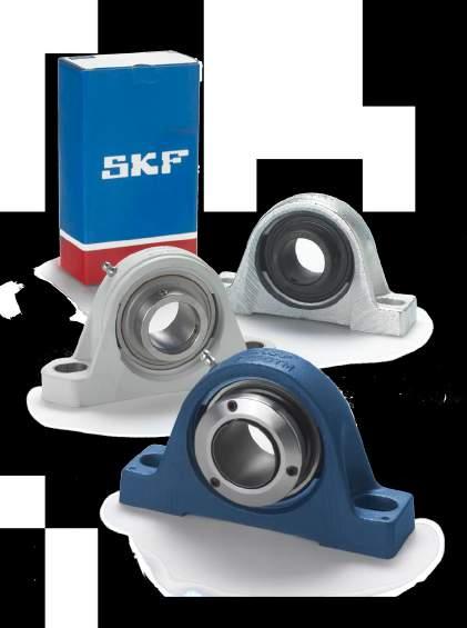

248
249 Engineered Y-bearing units Y-bearings and Y-bearing units for extreme temperatures Y-bearings for extreme temperatures Y-bearing units for extreme temperatures Data general Selection of bearing size Axial load carrying capacity Maintenance Additional information Product tables 6.1 Y-bearings for extreme temperatures, metric shafts inch shafts Y-bearing plummer block units for extreme temperatures, metric shafts inch shafts Flanged Y-bearing units with a cast housing with a square flange, for extreme temperatures, metric shafts inch shafts Flanged Y-bearing units with a cast housing with an oval flange, for extreme temperatures, metric shafts inch shafts SKF ConCentra ball bearing units Design Data general Product tables 6.5 SKF ConCentra ball bearing units with a plummer block housing, metric shafts inch shafts Y-bearing units for the food industry Designs Data general Product tables 6.6 Y-bearing plummer block units for the food industry, metric shafts inch shafts Y-bearing plummer block units with a short base for the food industry, metric shafts inch shafts Flanged Y-bearing units with a housing with a square flange, for the food industry metric shafts inch shafts Flanged Y-bearing units with a housing with an oval flange, for the food industry, metric shafts inch shafts Y-bearing take-up units for the food industry, metric shafts inch shafts

 flanged Y-bearing units They meet widely differing demands: reduced machine operating costs extended maintenance-free service life high operational reliability, even in severe environments Fig.")
250 Y-bearings and Y-bearing units for extreme temperatures For bearing arrangements that have to operate at extreme temperatures, as low as 150 C or as high as 350 C, or that have to withstand very wide temperature variations, e.g. in kiln trucks, furnaces or the conveyor systems of lacquering equipment, standard rolling bearings are unsuitable. SKF has therefore developed temperature-tolerant products: Fig. 1 Y-bearings ( fig. 1) Y-bearing plummer (pillow) block units ( fig. 2) flanged Y-bearing units They meet widely differing demands: reduced machine operating costs extended maintenance-free service life high operational reliability, even in severe environments Fig. 2 The bearings and units for extreme temperatures, belonging to the SKF standard assortment, are described below and listed in the relevant product tables. On demand, SKF can produce bearings for extreme temperatures, engineered to meet specific needs. For additional information, contact the SKF application engineering service. 248
251 Y-bearings for extreme temperatures SKF Y-bearings for extreme temperatures have a design corresponding to that of Y-bearings in the YAR 2-2FW series with grub screws. The characteristic features of these bearings include large radial internal clearance, special cages and shields. All surfaces of extreme temperature Y-bearings are manganese phosphated. This provides protection against corrosion and improves running properties. SKF Y-bearings for extreme temperatures are available in two different designs: Fig. 3 The VA201 design ( fig. 3a) is equipped with a riveted steel cage and a steel shield with a flinger on both sides. These Y-bearings, lubricated with an extreme-temperature polyalkylene glycol graphite paste, are intended for operating temperatures between 40 and +250 C. The VA228 design ( fig. 3b), like the VA201 design, is equipped with a shield and a flinger on both sides. However, the VA228 design uses a coronet cage made of graphite, which also serves as a lubricant. The permissible operating temperature range for these bearings is between 150 and +350 C. a b 6 249

 The cast housings of these Y-bearing units are dimensionally interchangeable with standard Y-bearing housings, except for a few sizes, where some")

252 Y-beraings and Y-bearing units for extreme temperatures Y-bearing units for extreme temperatures Y-bearing units for extreme temperatures have grey cast iron housings with zinc-coated surfaces and are available in three different designs: Fig. 4 plummer block units ( fig. 4) flanged units with a housing with a square flange and four bolt holes ( fig. 5) flanged units with a housing with an oval flange and two bolt holes ( fig. 6) The cast housings of these Y-bearing units are dimensionally interchangeable with standard Y-bearing housings, except for a few sizes, where some dimensions differ slightly. The housings are zinc-coated to provide better protection against corrosion. The housings do not have a grease fitting, as the incorporated bearings are lubricated for life. The housing bore, which is coated with a lubricating paste, has tolerances to accommodate initial misalignment, even at extreme temperatures. Fig. 5 Fig
253 Data general Dimensions The boundary dimensions of Y-bearings for extreme temperatures are in accordance with ISO 9628:2006. The boundary dimensions of Y-bearing units for extreme temperatures are in accordance with ISO 3228:1993. Tolerances The bore and outside diameter of Y-bearings for extreme temperatures are produced to tolerances indicated in table 1. The values specified there for the bore diameter of the bearings are slightly tighter than those specified in ISO 9628:2006. Since the bearings have a special surface treatment, there may be slight deviations from the standard tolerances. However, these deviations will not influence mounting or bearing performance. The tolerance for the height of the shaft axis above the support surface of the plummer block units, dimension H 1, is 0/ 0,25 mm. Radial internal clearance SKF Y-bearings for extreme temperatures and the corresponding Y-bearing units have twice the C5 clearance for deep groove ball bearings in accordance with ISO 5753:1991. Clearance limits are listed in table 2 and are valid before mounting, under zero measuring load. Tolerances of Y-bearings for extreme temperatures Nominal Bore Outside diameter diameter diameter d, D Deviation Deviation over incl. high low high low mm mm mm Table 1 Table 2 Radial internal clearance for Y-bearings for extreme temperatures Bearing size 1) Radial internal clearance from to min max μm ) For example size 06 includes all bearings based on a 6206 bearing: such as YAR 206-2FW/VA201, YAR FW/VA201 6 Speeds Y-bearings for extreme temperatures were developed for very slow speed applications e.g. a few revolutions per minute. However, experience has shown that it is possible to run these bearings for long periods at speeds up to 100 r/min without maintenance. If the bearings are to be used at higher speeds, contact the SKF application engineering service for additional information. 251
254 Y-beraings and Y-bearing units for extreme temperatures Selection of bearing size The requisite size is determined by the basic static load rating C 0, as Y-bearings and Y-bearing units for extreme temperatures rotate at very slow speeds. At extreme temperatures, the load carrying capacity of a bearing is reduced. This is taken into account by multiplying the basic static load rating C 0 by a temperature factor f T. The requisite basic static load rating can be determined by the formula C 0 req = 2 P 0 /f T where C 0 req = requisite basic static load rating, kn P 0 = equivalent static bearing load, kn f T = temperature factor ( table 3) The equivalent static bearing load P 0 is obtained from P 0 = 0,6 F r + 0,5 F a where F r = actual radial bearing load, kn F a = actual axial bearing load, kn When calculating P 0, the maximum load that can occur should be used and its radial and axial components inserted in the equation above. If P 0 < F r, then P 0 = F r should be used. For different loads and temperatures, the requisite basic static load rating C 0 req is shown in table 4. Using the requisite basic static load rating calculated from the above, or taken from table 4, a suitable Y-bearing or Y-bearing unit can be selected from the product tables. The Y-bearing or Y-bearing unit selected should have a C 0 value that is equal to or greater than the requisite value. Temperature factor f T Operating temperature C Factor f T , , , ,64 Table 3 Table 4 Requisite basic static load rating for different loads and temperatures Bearing Requisite basic static load rating C 0 req load for operating temperatures up to P C 200 C 250 C 300 C 350 C kn kn 0,5 1 1,05 1,11 1,2 1, ,1 2,22 2,5 3, ,2 4,44 5 6, ,3 6,67 7,5 9, ,4 8, , ,5 11,1 12,5 15, ,6 13, , ,7 15,5 17,5 21, ,8 17, ,9 19,9 22,5 28, , , ,1 24,5 27,5 34, ,2 26, , , ,5 40, ,4 31, ,5 33,3 37, , ,7 37,8 42, , , , , , , , , ,5 75, , , , ,5 252
255 Axial load carrying capacity Y-bearings and Y-bearing units for extreme temperatures have an axial load carrying capacity that is limited to 15% of the basic static load rating C 0, because of the large radial internal clearance and the way the bearing is locked on the shaft. Maintenance SKF Y-bearings and Y-bearing units for extreme temperatures are lubricated for life and therefore have no relubrication facility. Additional information Contact the SKF application engineering service for additional information about: selection of bearing type selection of bearing size arrangement design mounting and dismounting 6 253
256 Y-bearings for extreme temperatures, metric shafts d mm C D B r 1 r 2 d d 1 s 1 YAR.. /VA201 YAR.. /VA228 Dimensions Basic Mass Designations static load Bearing with a rating pressed steel cage one-piece coronet d D B C d 1 s 1 r 1,2 C 0 cage of graphite ~ min mm kn kg ,2 18,3 0,6 6,55 0,14 YAR 204-2FW/VA201 YAR 204-2FW/VA , ,7 19,8 0,6 7,8 0,17 YAR 205-2FW/VA201 YAR 205-2FW/VA , ,7 22,2 0,6 11,2 0,28 YAR 206-2FW/VA201 YAR 206-2FW/VA , ,1 25,4 1 15,3 0,41 YAR 207-2FW/VA201 YAR 207-2FW/VA , ,8 30, ,55 YAR 208-2FW/VA201 YAR 208-2FW/VA , ,8 30,2 1 21,6 0,60 YAR 209-2FW/VA201 YAR 209-2FW/VA , ,5 32,6 1 23,2 0,69 YAR 210-2FW/VA201 YAR 210-2FW/VA , ,1 33, ,94 YAR 211-2FW/VA201 YAR 211-2FW/VA , ,6 39,7 1,5 36 1,30 YAR 212-2FW/VA201 YAR 212-2FW/VA
257 Y-bearings for extreme temperatures, inch shafts d 3 /4 2 7 /16 in C D B r 1 r 2 d d 1 s 1 YAR.. /VA201 YAR.. /VA228 Dimensions Basic Mass Designations static load Bearing with a rating pressed steel cage one-piece coronet d D B C d 1 s 1 r 1,2 C 0 cage of graphite ~ min in/mm lbf/kn lb/kg 3/ YAR FW/VA201 YAR FW/VA228 19, ,2 18,3 0,6 6,55 0, YAR FW/VA201 YAR FW/VA228 25, , ,7 19,8 0,6 7,8 0, / YAR FW/VA201 YAR FW/VA228 30, , ,7 22,2 0,6 11,2 0, / YAR FW/VA201 YAR FW/VA228 31, , ,1 25,4 1 15,3 0, / YAR FW/VA201 YAR FW/VA228 36, , ,1 25,4 1 15,3 0, / YAR FW/VA201 YAR FW/VA228 38, , ,8 30, , / YAR FW/VA201 YAR FW/VA228 42, , ,8 30,2 1 21,6 0, / YAR FW/VA201 YAR FW/VA228 44, , ,8 30,2 1 21,6 0, / YAR FW/VA201 YAR FW/VA228 49, , ,5 32,6 1 23,2 0, YAR FW/VA201 YAR FW/VA228 50, , ,1 33, , / YAR FW/VA201 YAR FW/VA228 55, , ,1 33, , / YAR FW/VA201 YAR FW/VA228 61, , ,6 39,7 1,5 36 1,
258 Y-bearing plummer block units for extreme temperatures, metric shafts d mm d s 1 B H G H 1 N 1 H 2 A J L N Dimensions Basic Mass Designations static Y-bearing unit with a load pressed steel one-piece coronet d A B H H 1 H 2 J L N N 1 G s 1 rating cage cage of graphite C 0 mm kn kg , ,5 11, ,3 6,55 0,57 SY 20 TF/VA201 SY 20 TF/VA , , ,5 11, ,8 7,8 0,73 SY 25 TF/VA201 SY 25 TF/VA , ,9 16,5 117, , ,2 11,2 1,10 SY 30 TF/VA201 SY 30 TF/VA , , ,4 15,3 1,45 SY 35 TF/VA201 SY 35 TF/VA , , , , ,2 19 1,80 SY 40 TF/VA201 SY 40 TF/VA , ,6 143, , ,2 21,6 2,20 SY 45 TF/VA201 SY 45 TF/VA , , ,6 23,2 2,70 SY 50 TF/VA201 SY 50 TF/VA , ,5 23,8 171, , ,4 29 3,60 SY 55 TF/VA201 SY 55 TF/VA ,1 139,5 69, , , ,7 36 4,45 SY 60 TF/VA201 SY 60 TF/VA
259
260 Y-bearing plummer block units for extreme temperatures, inch shafts d 3 /4 2 7 /16 in d s 1 B H G H 1 N 1 H 2 A J L N Dimensions Designations Y-bearing unit with a pressed steel cage one-piece coronet d A B H H 1 H 2 J L N N 1 G s 1 cage of graphite in/mm 3/ / SY 3/4 TF/VA201 SY 3/4 TF/VA228 19, , ,5 11, , / SY 1. TF/VA201 SY 1. TF/VA228 25, , , ,5 11, ,8 1 3 / / SY 1.3/16 TF/VA201 SY 1.3/16 TF/VA228 30, , , , , ,2 1 1 / / SY 1.1/4 TF/VA201 SY 1.1/4 TF/VA228 31, , , ,4 1 7 / / SY 1.7/16 TF/VA201 SY 1.7/16 TF/VA228 36, , , ,4 1 1 / / SY 1.1/2 TF/VA201 SY 1.1/2 TF/VA228 38, , , , , , / / SY 1.11/16 TF/VA201 SY 1.11/16 TF/VA228 42, , ,6 143, , ,2 1 3 / / SY 1.3/4 TF/VA201 SY 1.3/4 TF/VA228 44, , ,6 143, , , / / SY 1.15/16 TF/VA201 SY 1.15/16 TF/VA228 49, , , , / SY 2. TF/VA201 SY 2. TF/VA228 50, , ,5 23,8 171, , ,4 2 3 / / SY 2.3/16 TF/VA201 SY 2.3/16 TF/VA228 55, , ,5 23,8 171, , ,4 2 7 / / SY 2.7/16 TF/VA201 SY 2.7/16 TF/VA228 61, ,1 139,5 69, , ,7 258
261 Designations Basic Mass Y-bearing unit with a static pressed steel cage one-piece coronet load cage of graphite rating C 0 lbf/kn lb/kg SY 3/4 TF/VA201 SY 3/4 TF/VA ,55 0,57 SY 1. TF/VA201 SY 1. TF/VA ,8 0,73 SY 1.3/16 TF/VA201 SY 1.3/16 TF/VA ,2 1,10 SY 1.1/4 TF/VA201 SY 1.1/4 TF/VA ,3 1,45 SY 1.7/16 TF/VA201 SY 1.7/16 TF/VA ,3 1,45 SY 1.1/2 TF/VA201 SY 1.1/2 TF/VA ,80 SY 1.11/16 TF/VA201 SY 1.11/16 TF/VA ,6 2,20 SY 1.3/4 TF/VA201 SY 1.3/4 TF/VA ,6 2,20 SY 1.15/16 TF/VA201 SY 1.15/16 TF/VA ,2 2,70 SY 2. TF/VA201 SY 2. TF/VA ,60 SY 2.3/16 TF/VA201 SY 2.3/16 TF/VA ,55 SY 2.7/16 TF/VA201 SY 2.7/16 TF/VA ,
262 Flanged Y-bearing units with a cast housing with a square flange for extreme temperatures, metric shafts d mm A 1 N d B G T A 2 J L Dimensions Basic Mass Designations static Y-bearing unit with a load pressed steel cage one-piece coronet d A 1 A 2 B J L N G T rating cage of graphite C 0 mm kn kg 20 29, , , ,3 6,55 0,60 FY 20 TF/VA201 FY 20 TF/VA , , ,8 7,8 0,77 FY 25 TF/VA201 FY 25 TF/VA , ,1 82, , ,2 11,2 1,10 FY 30 TF/VA201 FY 30 TF/VA , , , ,4 15,3 1,40 FY 35 TF/VA201 FY 35 TF/VA , ,2 101, , ,2 19 1,90 FY 40 TF/VA201 FY 40 TF/VA , , ,2 21,6 2,10 FY 45 TF/VA201 FY 45 TF/VA , , ,6 23,2 2,50 FY 50 TF/VA201 FY 50 TF/VA , , ,4 29 3,60 FY 55 TF/VA201 FY 55 TF/VA , ,7 36 4,60 FY 60 TF/VA201 FY 60 TF/VA
263 Flanged Y-bearing units with a cast housing with a square flange for extreme temperatures, inch shafts d 3 /4 2 7 /16 in A 1 N d B G T A 2 J L Dimensions Basic Mass Designations static Y-bearing unit with a load pressed steel cage one-piece coronet d A 1 A 2 B J L N G T rating cage of graphite C 0 in/mm lbf/kn lb/kg 3/ / FY 3/4 TF/VA201 FY 3/4 TF/VA228 19,05 29, , , ,3 6,55 0, / FY 1. TF/VA201 FY 1. TF/VA228 25, , , ,8 7,8 0, / / FY 1.3/16 TF/VA201 FY 1.3/16 TF/VA228 30,163 32, ,1 82, , ,2 11,2 1, / / FY 1.1/4 TF/VA201 FY 1.1/4 TF/VA228 31,75 34, , , ,4 15,3 1, / / FY 1.7/16 TF/VA201 FY 1.7/16 TF/VA228 36,513 34, , , ,4 15,3 1, / / FY 1.1/2 TF/VA201 FY 1.1/2 TF/VA228 38,1 38, ,2 101, , ,2 19 1, / / FY 1.11/16 TF/VA201 FY 1.11/16 TF/VA228 42, , , ,2 21,6 2, / / FY 1.3/4 TF/VA201 FY 1.3/4 TF/VA228 44, , , ,2 21,6 2, / / FY 1.15/16 TF/VA201 FY 1.15/16 TF/VA228 49, , , ,6 23,2 2, / FY 2. TF/VA201 FY 2. TF/VA228 50,8 47, , ,4 29 3, / / FY 2.3/16 TF/VA201 FY 2.3/16 TF/VA228 55,563 47, , ,4 29 3, / / FY 2.7/16 TF/VA201 FY 2.7/16 TF/VA228 61, , ,7 36 4,
264 Flanged Y-bearing units with a cast housing with an oval flange for extreme temperatures, metric shafts d mm N A 1 d B J H G T A 2 L Dimensions Basic Mass Designations static Y-bearing unit with a load pressed one-piece coronet d A 1 A 2 B H J L N G T rating steel cage cage of graphite C 0 mm kn kg 20 24, ,7 60,3 11, ,6 6,55 0,50 FYT 20 TF/VA201 FYT 20 TF/VA , , , ,8 7,8 0,63 FYT 25 TF/VA201 FYT 25 TF/VA , ,1 141,5 116, , ,2 11,2 0,93 FYT 30 TF/VA201 FYT 30 TF/VA , , , , ,4 15,3 1,25 FYT 35 TF/VA201 FYT 35 TF/VA , ,2 171,5 143, , ,2 19 1,65 FYT 40 TF/VA201 FYT 40 TF/VA ,2 178,5 148, , ,2 21,6 1,80 FYT 45 TF/VA201 FYT 45 TF/VA , , , ,6 23,2 2,15 FYT 50 TF/VA201 FYT 50 TF/VA ,6 20,6 55, , ,8 29 3,30 FYT 55 TF/VA201 FYT 55 TF/VA
265
266 Flanged Y-bearing units with a cast housing with an oval flange for extreme temperatures, inch shafts d 3 /4 2 3 /16 in N A 1 d B J H G T A 2 L Dimensions Designations Y-bearing unit with a pressed steel cage one-piece coronet d A 1 A 2 B H J L N G T cage of graphite in/mm 3/ / FYT 3/4 TF/VA201 FYT 3/4 TF/VA228 19,05 24, ,7 60,3 11, , / FYT 1. TF/VA201 FYT 1. TF/VA228 25, , , , ,8 1 3 / / FYT 1.3/16 TF/VA201 FYT 1.3/16 TF/VA228 30,163 32, ,1 141,5 116, , ,2 1 1 / / FYT 1.1/4 TF/VA201 FYT 1.1/4 TF/VA228 31,75 34, , , , ,4 1 7 / / FYT 1.7/16 TF/VA201 FYT 1.7/16 TF/VA228 36,513 34, , , , ,4 1 1 / / FYT 1.1/2 TF/VA201 FYT 1.1/2 TF/VA228 38,1 38, ,2 171,5 143, , , / / FYT 1.11/16 TF/VA201 FYT 1.11/16 TF/VA228 42, ,2 178,5 148, , ,2 1 3 / / FYT 1.3/4 TF/VA201 FYT 1.3/4 TF/VA228 44, ,2 178,5 148, , , / / FYT 1.15/16 TF/VA201 FYT 1.15/16 TF/VA228 49, , , , , / FYT 2. TF/VA201 FYT 2. TF/VA228 50,8 47,6 20,6 55, , ,8 2 3 / / FYT 2.3/16 TF/VA201 FYT 2.3/16 TF/VA228 55,563 47,6 20,6 55, , ,8 264
267 Designations Basic Mass Y-bearing unit with a static pressed steel cage one-piece coronet load cage of graphite rating C 0 lbf/kn lb/kg FYT 3/4 TF/VA201 FYT 3/4 TF/VA ,55 0,50 FYT 1. TF/VA201 FYT 1. TF/VA ,8 0,62 FYT 1.3/16 TF/VA201 FYT 1.3/16 TF/VA ,2 0,92 FYT 1.1/4 TF/VA201 FYT 1.1/4 TF/VA ,3 1,30 FYT 1.7/16 TF/VA201 FYT 1.7/16 TF/VA ,3 1,25 FYT 1.1/2 TF/VA201 FYT 1.1/2 TF/VA ,70 FYT 1.11/16 TF/VA201 FYT 1.11/16 TF/VA ,6 1,80 FYT 1.3/4 TF/VA201 FYT 1.3/4 TF/VA ,6 1,80 FYT 1.15/16 TF/VA201 FYT 1.15/16 TF/VA ,2 2,15 FYT 2. TF/VA201 FYT 2. TF/VA ,30 FYT 2.3/16 TF/VA201 FYT 2.3/16 TF/VA ,

268 SKF ConCentra ball bearing units SKF ConCentra ball bearing units ( fig. 1) are relatively new within the SKF manufacturing programme. They are currently available as plummer block units for: Fig. 1 metric shafts from 25 to 60 mm inch shafts from 1 to 2 15 /16 inch They are identified by the series designation SY.. PF. SKF ConCentra ball bearing units are based on the cast iron SY plummer block units that are in use worldwide. SKF ConCentra ball bearing units are also available with flanged housings. For additional information, contact the SKF application engin eering service. What sets the SKF ConCentra ball bearing unit apart from any other Y-bearing unit is its unique 360 locking mechanism. The locking mechanism is based on two mating surfaces, each containing precision engineered inclined serrations. One set of serrations is machined into the bearing bore; the other set is machined into the shaft sleeve. The near perfect 360 grip on the shaft virtually eliminates shaft damage and the possibility of fretting corrosion. The stepped sleeve is equipped with a mounting and a pressure collar ( fig. 2). By tightening the grub (set) screws in the mounting collar, using the hexagonal key supplied with each unit, the pressure collar forces the inner ring up the inclined planes of the stepped sleeve, to provide a true concentric tight fit on the shaft ( fig. 3). SKF ConCentra ball bearing units are particularly well suited for use under the following conditions: 266
269 applications where commercial or hollow shafts are used high speed, moderate load applications where long service life, low noise and vibration levels and quick replacement are prerequisites Fig. 2 They can therefore cover all requirements for bearing arrangements in ventilation systems where there is a need to run continuously and quietly for long periods without requiring very much attention. Design SKF ConCentra ball bearing units are readyto-mount and ready-to-operate. They are filled with a high-quality, long-lasting grease that provides maintenance-free operation in most cases. For operating conditions that make relubrication necessary, the units are provided with a grease fitting. SKF ConCentra ball bearing units consist of: Fig. 3 a deep groove ball bearing based on the 62 series, with the inner ring extended on both sides. The bore of the inner ring is serrated to accommodate the SKF ConCentra locking method. The surface of the outer ring is convex an SKF ConCentra stepped sleeve an SY 500 M series plummer block housing for metric shafts, or an SY 500 U/AH series pillow block housing for inch shafts 6 The product tables on pages 270 to 273 list the boundary dimensions as well as the most important performance data for SKF ConCentra ball bearing units for metric and inch shafts. Detailed information about these bearing units can be found in the publication SKF ConCentra ball bearing units true concentric locking, for fast and reliable mounting and in the SKF Interactive Engineering Catalogue, available online at 267
270 SKF ConCentra ball bearing units Data general Dimensions The housing boundary dimensions of SKF ConCentra ball bearing units with a cast plummer block housing are in accordance with ISO 3228:1993, ANSI/ABMA or JIS B Tolerances The tolerance for the shaft centre height H 1 above the support surface is: ± 0,25 mm for plummer block units with a bore diameter 40 mm ± 0,30 mm for larger plummer block units Radial internal clearance for SKF ConCentra ball bearing units Bearing size 1) Radial internal clearance from to min max μm Table 1 1) For example, bearing size 07 includes all bearings based on a Y 207 bearing, such as YSP 207, YSP F/AH, YSP F/AH and YSP F/AH The tolerances for the shaft centre height H 1 are tighter than specified in ISO 3228:1993. Radial internal clearance SKF ConCentra ball bearing units are manufactured as standard with the internal clearance listed in table 1. The values specified there are similar to the values of Group 3 radial clearance listed in ISO 9628:2006, except for the size 215 where values are slightly lower. Misalignment SKF ConCentra ball bearing units can accommodate up to 2 of initial misalignment if they are relubricated during operation. Otherwise misalignment of up to 5 can be accommodated. Additionally, operational shaft deflections of a few minutes or arc can be permitted. 268
271 Load carrying ability of the housings The housings are made of grey cast iron EN-GJL HB195 in accordance with EN 1561:1997 and can withstand the same dynamic and static loads as the bearings they incorporate. Attachment to the support surface SKF ConCentra ball bearing units have two bolt holes in the housing base through which they can be attached to their support surface with fasteners. Grease fill Standard design SKF ConCentra ball bearing units are filled with a high-quality, long-lasting grease with a lithium-calcium thickener that has a consistency of 2 on the NLGI scale
272 SKF ConCentra ball bearing units with a plummer block housing, metric shafts d mm N d s 1 B H 1 H G J N 1 H 2 A J L Dimensions Basic load Fatigue Designation ratings load limit dynamic static d A B H H 1 H 2 J L N N 1 G s 1 C C 0 P u mm kn kn ,5 36, ,5 11, ,8 0,335 SY 25 PF ,5 42, , , ,5 11,2 0,475 SY 30 PF , ,7 25,5 15,3 0,655 SY 35 PF , , , ,7 19 0,8 SY 40 PF , , , ,5 33,2 21,6 0,915 SY 45 PF ,5 57, ,5 35,1 23,2 0,98 SY 50 PF , , , ,6 29 1,25 SY 55 PF ,9 26,5 190, , ,8 52,7 36 1,53 SY 60 PF 270
273 Designations Limiting Mass Bearing unit Separate components speed Housing Bearing r/min kg SY 25 PF SY 505 M YSP 205-2F ,85 SY 30 PF SY 506 M YSP 206-2F ,20 SY 35 PF SY 507 M YSP 207-2F ,55 SY 40 PF SY 508 M YSP 208-2F ,05 SY 45 PF SY 509 M YSP 209-2F ,25 SY 50 PF SY 510 M YSP 210-2F ,70 SY 55 PF SY 511 M YSP 211-2F ,85 SY 60 PF SY 512 M YSP 212-2F ,
274 SKF ConCentra ball bearing units with a plummer block housing, inch shafts d /16 in N d s 1 B H 1 H G J N 1 H 2 A J L Dimensions Designation d A B H H 1 H 2 J L N N 1 G s 1 in/mm / SY 1.PF/AH 25, , , ,5 11, ,3 1 3 / / SY 1.3/16 PF/AH 30, , ,9 16,5 117, , ,5 1 1 / / SY 1.1/4 PF/AH 31, , , ,4 1 3 / / SY 1.3/8 PF/AH 34, , , ,4 1 7 / / SY 1.7/16 PF/AH 36, , , ,4 1 1 / / SY 1.1/2 PF/AH 38, , , , , , / / SY 1.11/16 PF/AH 42,863 48,3 50, ,0 20,6 143, , , / / SY 1.15/16 PF/AH 49, , ,5 2 3 / / SY 2.3/16 PF/AH 55,563 60,4 57, ,5 23,8 171, , ,0 2 7 / / SY 2.7/16 PF/AH 61, , , , , , / / SY 2.11/16 PF/AH 68, , , , / / SY 2.15/16 PF/AH 74,613 71,6 63, ,6 32,8 215, , ,8 272
275 Designations Basic load Fatigue Limiting Mass Bearing unit Separate components ratings load limit speed Housing Bearing dynamic static C C 0 P u lbf/kn lbf/kn r/min lb/kg SY 1.PF/AH SY 505 U/AH YSP F/AH ,8 0,335 0,77 SY 1.3/16 PF/AH SY 506 U/AH YSP F/AH ,5 11,2 0,475 1,30 SY 1.1/4 PF/AH SY 507 U/AH YSP F/AH ,5 15,3 0,655 1,65 SY 1.3/8 PF/AH SY 507 U/AH YSP F/AH ,5 15,3 0,655 1,60 SY 1.7/16 PF/AH SY 507 U/AH YSP F/AH ,5 15,3 0,655 1,55 SY 1.1/2 PF/AH SY 508 U/AH YSP F/AH ,7 19 0,8 1,95 SY 1.11/16 PF/AH SY 509 U/AH YSP F/AH ,2 21,6 0,915 2,40 SY 1.15/16 PF/AH SY 510 U/AH YSP F/AH ,1 23,2 0,98 2,85 SY 2.3/16 PF/AH SY 511 U/AH YSP F/AH ,6 29 1,25 3,65 SY 2.7/16 PF/AH SY 512 U/AH YSP F/AH ,7 36 1,53 5,00 SY 2.11/16 PF/AH SY 513 U/AH YSP F/AH ,2 40 1,7 6,15 SY 2.15/16 PF/AH SY 515 U/AH YSP F/AH ,3 49 2,04 7,
276 Y-bearing units for the food industry To meet the requirements of the food, beverage and pharmaceutical processing industries, SKF has developed a special range of Y-bearing units. The housings of these Y-bearing units for the food industry are made of a chemical and corrosion resistant composite material, designed to withstand frequent washdowns. The non-porous surface resists the accumulation of bacteria-forming food particles, and the lightgrey colour makes visual inspection easy. The units are equipped with Y-bearings made of stainless steel (YAR 2-2RF/HV series) or zinc-coated steel (YAR 2-2RF/VE495 series). The bearing inner ring is extended on both sides and is locked on the shaft with grub screws. The bearings can be relubricated. The sealing arrangement consists of a multilip seal, supported by a stainless steel insert, a stainless steel flinger, and a food-compatible rubber backed seal gasket on both sides ( fig. 1). Fig. 1 The units are lubricated with food-grade grease. The adjacent table shows the Y-bearings and Y-bearing units available for the food industry. Designs SKF Y-bearing units for the food industry are available in two designs: the L design and the KC design. The L design was developed specifically for food and beverage applications, and is characterized by its smooth surfaces and rounded shapes, for easy cleaning. The KC design is a unit optimized for handling shock loads and high vibration levels. It incorp orates a steel coil, embedded in the polymer, to provide high dimensional stability and excellent strength. Y-bearing units in the L design are available with five different housings: plummer block units in the SYL.. TH and SYL.. TR/VE495 series ( fig. 2a) flanged units with a housing with a square flange in the FYL.. THR and FYL.. TR/VE495 series ( fig. 2b) flanged units with a housing with an oval flange in the FYTL.. THR and FYTL.. TR/VE495 series ( fig. 2c) short base units in the SYFL.. TH and SYFL.. TR/VE495 series ( fig. 2d) take-up units in the TUL.. TH and TUL.. TR/VE495 series ( fig. 2e) 274
 SYKC")
 FYTBKC 5(00) TUL 5(00) YAR")


277 Y-bearing unit Y-bearing housings for the food industry Y-bearings SYL 5(00) SYKC 5(00) SYFL 5(00) FYL 5(00) FYKC 5(00) N FYTL 5(00) FYTBKC 5(00) TUL 5(00) YAR 2-2RF/HV SYL.. TH SYFL.. TH FYL.. THR FYTL.. THR TUL.. TH mm 3/4 1 1 /2 in mm 3/4 1 1 /2 in mm 3/4 1 1 /2 in mm 3/4 1 1 /2 in mm 3/4 1 1 /2 in SYKC.. NTH FYKC.. NTH FYTBKC.. NTH mm mm 3/4 1 1 /2 in mm 3/4 1 1 /4 in YAR 2-2RF/VE495 SYL.. TR/VE495 SYFL.. TR/VE495 FYL.. TR/VE495 FYTL.. TR/VE495 TUL.. TR/VE mm mm mm mm mm SYKC.. NTR/VE495 FYKC.. NTR/VE495 FYTBKC.. NTR/VE mm mm mm Fig. 2 6 a b c d e 275

 flanged units with a housing with a square flange in the FYKC.. NTH and FYKC.. NTR/VE495 series ( fig.")
278 Y-bearing units for the food industry Fig. 3 Y-bearing units in the KC design are available with three different housings: a plummer block units in the SYKC.. NTH and SYKC.. NTR/VE 495 series ( fig. 3a) flanged units with a housing with a square flange in the FYKC.. NTH and FYKC.. NTR/VE495 series ( fig. 3b) flanged units with a housing with an oval flange in the FYTBKC.. NTH and FYTBKC.. NTR/VE495 series ( fig. 3c) b c 276
279 Data general Dimensions The boundary dimensions of SKF Y-bearing housings for food industry have not been standardized either nationally or internationally, but are common in the marketplace. They are similar to cast iron housings and pressed steel housings according to ISO 3228:1993 or JIS B In nearly all cases, the housings are dimensionally interchangeable with cast iron housings or pressed steel housings of similar shape and same size. For additional information about the tolerances of the inner ring bore, refer to the section Y-bearings, page 89. Radial internal clearance Y-bearing plummer block units, flanged units and take-up units for the food industry have the same radial internal clearance as the individual bearings that they incorporate. For additional information about the radial internal clearance, refer to the section Y-bearings, page 90. Tolerances For all Y-bearing units for the food industry, the bearing is matched to the housing bore diameter so that the outer ring is prevented from turning in its seat, but able to accommodate misalignment. For Y-bearing plummer block units, the tolerances for the shaft centre height H 1 ( fig. 4) above the support surface is +/ 0,31 mm. Tolerances for Y-bearing take-up units: The tolerance for the distance between the guide surfaces, dimension H 1, is 0/ 0,4 mm ( fig. 5). The tolerance for the width of the guide surfaces, dimension A 1 ( fig. 5) is 0/+0,4 mm. Materials Housings in the L design are injection moulded from a glass fibre reinforced polyester material. The grease fitting and housing inserts are made of stainless steel. Housings in the KC design are made of injection moulded glass fibre reinforced polyamide. A steel coil embedded in the housing adds greater stability to its form and excellent strength. The bolt holes in the housing have stainless steel inserts and there is a stainless steel grease fitting for relubrication. The housings are light-grey for easier visual inspection. 6 Fig. 4 Fig. 5 H 1 H 1 A 1 277
280 Y-bearing units for the food industry Load carrying ability of the housings Housings for the food industry can withstand the same dynamic and static loads as the Y-bearings they incorporate. They can be used in applications where shock loads or variable axial loads occur. KC series flanged composite housings for the food industry have a recess ( fig. 6) at the back for accurate positioning against an appropriate shoulder that is either machined, welded or bolted to the wall ( fig. 7). Furthermore, these features relieve the attachment bolts of radial forces. 3,2 H14 D a H11 Fig. 6 Axial load carrying capacity The axial load carrying capacity of a Y-bearing unit for the food industry is approximately 20% of the basic dynamic load rating C, if unhardened shafts are used and the grub screws are properly tightened. If the inner ring is supported by an abutment on the shaft, the axial load carrying capacity depends on the nature of this abutment. However, the axial load should not exceed 0,25 C 0. Fig. 7 Attaching to a support surface Plummer block units have two bolt holes in the housing base so that they can be bolted to their support surface. The shape and position of the bolt holes vary between different housings. Housings in the: SYKC and SYL designs have oblong bolt holes, reinforced with zinc coated sheet steel or stainless steel inserts SYFL series have threaded stainless steel inserts in the support base a b 278
281 P 120 P 55 Fig. 8 Fig. 9 If the loads acting on a housing are between 55 and 120 ( fig. 8), Y-bearing plummer block units for the food industry should be doweled to the support surface, or stops should be provided in the direction of the load. Flanged Y-bearing units for the food industry have two or four bolt holes through which they can be attached to their support surface with attachment bolts. The bolt holes are round and reinforced with stainless steel inserts. In the absence of a centring shoulder and where heavy loads apply, SKF recommends doweling the housing to its support surface. For additional information, contact the SKF application engin eering service. Grease fills Y-bearing units for the food industry are filled with a non-toxic, food-grade grease based on a PAO oil, containing an aluminium-complex soap as thickener (food industry approved USDA H1). For additional information about lubricants and lubrication, refer to the section Lubrication and maintenance, starting on page 48. End covers For protection and safety reasons, units at the end of a shaft should have an end cover ( fig. 9). The product tables show the end covers together with the units that they are compatible with. The designation of the end cover is shown, along with the distance that it protrudes from the housing. End covers for the L and KC designs are available as accessories. Additionally, for the L design, covers incorporating a seal are available for through shafts. For additional information about end covers, refer to the section Design of Y-bearing arrangements, page
282 Y-bearing plummer block units for the food industry, metric shafts d mm A 1 A 5 A 6 N 1 d s 1 B H G N H 1 H 2 A J L SYL ECL and ECL.. B Dimensions Basic load Fatigue Designation ratings load Bearing unit dynamic static limit d A A 1 B H H 1 H 2 J L N N 1 G s 1 C C 0 P u mm kn kn , ,3 14, ,3 10,8 6,55 0,28 SYL 20 TH 38 22, ,3 14, ,3 12,7 6,55 0,28 SYL 20 TR/VE , , , ,3 10,8 6,55 0,28 SYKC 20 NTH , , , ,3 12,7 6,55 0,28 SYKC 20 NTR/VE ,6 34, ,5 14, ,8 11,9 7,8 0,335 SYL 25 TH 38 24,6 34, ,5 14, ,8 14 7,8 0,335 SYL 25 TR/VE ,1 70,5 36, , ,8 11,9 7,8 0,335 SYKC 25 NTH ,1 70,5 36, , ,8 14 7,8 0,335 SYKC 25 NTR/VE ,3 38, ,9 17, ,2 16,3 11,2 0,475 SYL 30 TH 46 26,3 38, ,9 17, ,2 19,5 11,2 0,475 SYL 30 TR/VE , , ,5 14, ,2 16,3 11,2 0,475 SYKC 30 NTH , , ,5 14, ,2 19,5 11,2 0,475 SYKC 30 NTR/VE ,3 42, , ,4 21,6 15,3 0,655 SYL 35 TH 48 32,3 42, , ,4 25,5 15,3 0,655 SYL 35 TR/VE , , ,5 14, ,4 21,6 15,3 0,655 SYKC 35 NTH , , ,5 14, ,4 25,5 15,3 0,655 SYKC 35 NTR/VE ,3 49, ,2 19, ,2 24,7 19 0,8 SYL 40 TH 54 36,3 49, ,2 19, ,2 30,7 19 0,8 SYL 40 TR/VE , , ,5 14, ,2 24,7 19 0,8 SYKC 40 NTH , , ,5 14, ,2 30,7 19 0,8 SYKC 40 NTR/VE
283 SYKC ECY Designations Limiting Mass Appropriate covers Bearing unit Separate components speed Bearing Designations Dimension Housing Bearing with shaft unit End cover Cover tolerance closed open A 5 A 6 h6 r/min kg mm SYL 20 TH SYL 504 YAR 204-2RF/HV ,27 ECL 204 ECL 204 B 20,5 20,5 SYL 20 TR/VE495 SYL 504 YAR 204-2RF/VE ,27 ECL 204 ECL 204 B 20,5 20,5 SYKC 20 NTH SYKC 504 N YAR 204-2RF/HV ,24 ECY ,5 SYKC 20 NTR/VE495 SYKC 504 N YAR 204-2RFG/VE ,24 ECY ,5 SYL 25 TH SYL 505 YAR 205-2RF/HV ,33 ECL 205 ECL 205 B SYL 25 TR/VE495 SYL 505 YAR 205-2RF/VE ,33 ECL 205 ECL 205 B SYKC 25 NTH SYKC 505 N YAR 205-2RF/HV ,29 ECY SYKC 25 NTR/VE495 SYKC 505 N YAR 205-2RFG/VE ,29 ECY SYL 30 TH SYL 506 YAR 206-2RF/HV ,52 ECL 206 ECL 206 B SYL 30 TR/VE495 SYL 506 YAR 206-2RF/VE ,52 ECL 206 ECL 206 B SYKC 30 NTH SYKC 506 N YAR 206-2RF/HV ,49 ECY SYKC 30 NTR/VE495 SYKC 506 N YAR 206-2RFG/VE ,49 ECY SYL 35 TH SYL 507 YAR 207-2RF/HV ,70 ECL 207 ECL 207 B SYL 35 TR/VE495 SYL 507 YAR 207-2RF/VE ,70 ECL 207 ECL 207 B SYKC 35 NTH SYKC 507 N YAR 207-2RF/HV ,66 ECY SYKC 35 NTR/VE495 SYKC 507 N YAR 207-2RFG/VE ,66 ECY SYL 40 TH SYL 508 YAR 208-2RF/HV ,92 ECL 208 ECL 208 B 30,5 33,5 SYL 40 TR/VE495 SYL 508 YAR 208-2RF/VE ,92 ECL 208 ECL 208 B 30,5 33,5 SYKC 40 NTH SYKC 508 N YAR 208-2RF/HV ,86 ECY ,5 SYKC 40 NTR/VE495 SYKC 508 N YAR 208-2RFG/VE ,86 ECY ,5 281
284 Y-bearing plummer block units for the food industry, inch shafts d 3 /4 1 1 /2 in A 1 N 1 d s 1 B H G N H 1 H 2 A J L Dimensions Basic load Fatigue Designation ratings load Bearing unit dynamic static limit d A A 1 B H H 1 H 2 J L N N 1 G s 1 C C 0 P u in/mm lbf/kn lbf/kn 3/ / SYL 3/4 TH 19, , ,3 14, ,3 10,8 6,55 0, / SYL 1.TH 25, ,6 34, ,5 14, ,8 11,9 7,8 0, / / SYL 1.1/4 TH 31, ,3 42, , ,4 21,6 15,3 0, / / SYL 1.1/2 TH 38, ,3 49, ,2 19, ,2 24,7 19 0,8 282
285 A 5 A 5 A 6 ECL ECL.. B Designations Limiting Mass Appropriate covers Bearing unit Separate components speed Bearing Designations Dimension Housing Bearing with shaft unit End cover Cover tolerance closed open A 5 A 6 h6 r/min lb/kg in/mm SYL 3/4 TH SYL 504 YAR RF/HV ECL 204 ECL B ,28 20,5 20,5 SYL 1.TH SYL 505 YAR RF/HV ECL 205 ECL B , SYL 1.1/4 TH SYL 507 YAR RF/HV ECL 207 ECL B , SYL 1.1/2 TH SYL 508 YAR RF/HV ECL 208 ECL B ,97 30,5 33,
286 Y-bearing plummer block units with a short base for the food industry, metric shafts d mm A 1 d s 1 B H H 1 G 1 A G J L Dimensions Basic load Fatigue Designation ratings load Bearing unit dynamic static limit d A A 1 B H H 1 J L G G 1 s 1 C C 0 P u mm kn kn 20 34,5 23, ,3 50,8 72,8 M ,3 10,8 6,55 0,28 SYFL 20 TH 34,5 23, ,3 50,8 72,8 M ,3 12,7 6,55 0,28 SYFL 20 TR/VE ,5 25,4 34,1 73,5 36,5 50,8 76,2 M ,8 11,9 7,8 0,335 SYFL 25 TH 39,5 25,4 34,1 73,5 36,5 50,8 76,2 M ,8 14 7,8 0,335 SYFL 25 TR/VE , , ,9 76,2 101 M ,2 16,3 11,2 0,475 SYFL 30 TH 42, , ,9 76,2 101 M ,2 19,5 11,2 0,475 SYFL 30 TR/VE ,5 32,5 42, ,6 82, M 10 15,5 25,4 21,6 15,3 0,655 SYFL 35 TH 47,5 32,5 42, ,6 82, M 10 15,5 25,4 25,5 15,3 0,655 SYFL 35 TR/VE ,2 100,5 49,2 88,9 120 M ,2 24,7 19 0,8 SYFL 40 TH ,2 100,5 49,2 88,9 120 M ,2 30,7 19 0,8 SYFL 40 TR/VE
287 A 5 A 5 A 6 ECL ECL.. B Designations Limiting Mass Appropriate covers Bearing unit Separate components speed Bearing Designations Dimension Housing Bearing with shaft unit End cover Cover tolerance closed open A 5 A 6 h6 r/min kg mm SYFL 20 TH SYFL 504 YAR 204-2RF/HV ,25 ECL 204 ECL 204 B 20,5 20,5 SYFL 20 TR/VE495 SYFL 504 YAR 204-2RF/VE ,25 ECL 204 ECL 204 B 20,5 20,5 SYFL 25 TH SYFL 505 YAR 205-2RF/HV ,32 ECL 205 ECL 205 B SYFL 25 TR/VE495 SYFL 505 YAR 205-2RF/VE ,32 ECL 205 ECL 205 B SYFL 30 TH SYFL 506 YAR 206-2RF/HV ,49 ECL 206 ECL 206 B SYFL 30 TR/VE495 SYFL 506 YAR 206-2RF/VE ,49 ECL 206 ECL 206 B SYFL 35 TH SYFL 507 YAR 207-2RF/HV ,67 ECL 207 ECL 207 B SYFL 35 TR/VE495 SYFL 507 YAR 207-2RF/VE ,67 ECL 207 ECL 207 B SYFL 40 TH SYFL 508 YAR 208-2RF/HV ,85 ECL 208 ECL 208 B 31,5 33,5 SYFL 40 TR/VE495 SYFL 508 YAR 208-2RF/VE ,85 ECL 208 ECL 208 B 31,5 33,
288 Y-bearing plummer block units with a short base for the food industry, inch shafts d 3 /4 1 1 /2 in A 1 d s 1 B H H 1 G 1 A G J L Dimensions Basic load Fatigue Designation ratings load Bearing unit dynamic static limit d A A 1 B H H 1 J L G G 1 s 1 C C 0 P u in/mm lbf/kn lbf/kn 3/ M SYFL 3/4 TH 19,05 34,5 23, ,3 50,8 72,8 M ,3 10,8 6,55 0, M SYFL 1. TH 25,4 39,5 25,4 34,1 73,5 36,5 50,8 76,2 M ,8 11,9 7,8 0, / M SYFL 1.1/4 TH 31,75 47,5 32,5 42, ,6 82, M 10 15,5 25,4 21,6 15,3 0, / M SYFL 1.1/2 TH 38, ,2 100,5 49,2 88,9 120 M ,2 24,7 19 0,8 286
289 A 5 A 5 A 6 ECL ECL.. B Designations Limiting Mass Appropriate covers Bearing unit Separate components speed Bearing Designations Dimension Housing Bearing with shaft unit End cover Cover tolerance closed open A 5 A 6 h6 r/min lb/kg in/mm SYFL 3/4 TH SYFL 504 YAR RF/HV ECL 204 ECL B ,26 20,5 20,5 SYFL 1. TH SYFL 505 YAR RF/HV ECL 205 ECL B , SYFL 1.1/4 TH SYFL 507 YAR RF/HV ECL 207 ECL B , SYFL 1.1/2 TH SYFL 508 YAR RF/HV ECL 208 ECL B ,90 31,5 33,
290 Flanged Y-bearing units with a housing with a square flange for the food industry, metric shafts d mm A 1 N A 5 d s 1 B G J L A 2 FYL T ECL ECL.. B Dimensions Basic load Fatigue Limiting Designation ratings load speed Bearing unit dynamic static limit with shaft d A 1 A 2 B D a J L N G s 1 T C C 0 P u tolerance h6 mm kn kn r/min 20 27,8 13, , ,3 36,3 10,8 6,55 0, FYL 20 THR 27,8 13, , ,3 36,3 12,7 6,55 0, FYL 20 TR/VE ,3 63, ,3 37,3 10,8 6,55 0, FYKC 20 NTH ,3 63, ,3 37,3 12,7 6,55 0, FYKC 20 NTR/VE ,3 34, ,8 36,7 11,9 7,8 0, FYL 25 THR 28 14,3 34, ,8 36,7 14 7,8 0, FYL 25 TR/VE ,1 74, ,8 38,8 11,9 7,8 0, FYKC 25 NTH ,1 74, ,8 38,8 14 7,8 0, FYKC 25 NTR/VE ,5 14,3 38, ,2 41,4 16,3 11,2 0, FYL 30 THR 31,5 14,3 38, ,2 41,4 19,5 11,2 0, FYL 30 TR/VE ,3 38,1 93,7 82, ,2 42,2 16,3 11,2 0, FYKC 30 NTH 33 15,3 38,1 93,7 82, ,2 42,2 19,5 11,2 0, FYKC 30 NTR/VE ,8 15,5 42, ,4 46,9 21,6 15,3 0, FYL 35 THR 34,8 15,5 42, ,4 46,9 25,5 15,3 0, FYL 35 TR/VE ,9 106, , ,4 46,4 21,6 15,3 0, FYKC 35 NTH ,9 106, , ,4 46,4 25,5 15,3 0, FYKC 35 NTR/VE , , ,2 53,2 24,7 19 0, FYL 40 THR 37, , ,2 53,2 30,7 19 0, FYL 40 TR/VE ,2 115,9 101, , ,2 54,2 24,7 19 0, FYKC 40 NTH ,2 115,9 101, , ,2 54,2 30,7 19 0, FYKC 40 NTR/VE
291 3,2 H14 D a H11 FYKC ECY Designations Mass Appropriate covers Bearing unit Separate components Bearing Designations Dimension Housing Bearing unit End cover Cover closed open A 5 kg mm FYL 20 THR FYL 504 YAR 204-2RFGR/HV 0,28 ECL 204 ECL 204 B 20,5 FYL 20 TR/VE495 FYL 504 YAR 204-2RF/VE495 0,28 ECL 204 ECL 204 B 20,5 FYKC 20 NTH FYKC 504 N YAR 204-2RF/HV 0,26 ECY ,5 FYKC 20 NTR/VE495 FYKC 504 N YAR 204-2RFG/VE495 0,26 ECY ,5 FYL 25 THR FYL 505 YAR 205-2RFGR/HV 0,34 ECL 205 ECL 205 B 22 FYL 25 TR/VE495 FYL 505 YAR 205-2RF/VE495 0,34 ECL 205 ECL 205 B 22 FYKC 25 NTH FYKC 505 N YAR 205-2RF/HV 0,33 ECY FYKC 25 NTR/VE495 FYKC 505 N YAR 205-2RFG/VE495 0,33 ECY FYL 30 THR FYL 506 YAR 206-2RFGR/HV 0,47 ECL 206 ECL 206 B 27 FYL 30 TR/VE495 FYL 506 YAR 206-2RF/VE495 0,46 ECL 206 ECL 206 B 27 FYKC 30 NTH FYKC 506 N YAR 206-2RF/HV 0,48 ECY FYKC 30 NTR/VE495 FYKC 506 N YAR 206-2RFG/VE495 0,48 ECY FYL 35 THR FYL 507 YAR 207-2RFGR/HV 0,67 ECL 207 ECL 207 B 29 FYL 35 TR/VE495 FYL 507 YAR 207-2RF/VE495 0,67 ECL 207 ECL 207 B 29 FYKC 35 NTH FYKC 507 N YAR 207-2RF/HV 0,66 ECY FYKC 35 NTR/VE495 FYKC 507 N YAR 207-2RFG/VE495 0,66 ECY FYL 40 THR FYL 508 YAR 208-2RFGR/HV 0,91 ECL 208 ECL 208 B 33,5 FYL 40 TR/VE495 FYL 508 YAR 208-2RF/VE495 0,91 ECL 208 ECL 208 B 33,5 FYKC 40 NTH FYKC 508 N YAR 208-2RF/HV 0,87 ECY ,5 FYKC 40 NTR/VE495 FYKC 508 N YAR 208-2RFG/VE495 0,87 ECY ,5 289
292 Flanged Y-bearing units with a housing with a square flange for the food industry, inch shafts d 3 /4 1 1 /2 in A 1 N d s 1 B FYL T A 2 G J L Dimensions Basic load Fatigue Limiting Designation ratings load speed Bearing unit dynamic static limit with shaft d A 1 A 2 B J L N G s 1 T C C 0 P u tolerance h6 in/mm lbf/kn lbf/kn r/min 3/ / FYL 3/4 THR 19,05 27,8 13, , ,3 36,3 10,8 6,55 0, / FYL 1. THR 25, ,3 34, ,8 36,7 11,9 7,8 0, / / FYL 1.1/4 THR 31,75 34,8 15,5 42, ,4 46,9 21,6 15,3 0, / / FYL 1.1/2 THR 38,1 37, , ,2 53,2 24,7 19 0,8 290
293 A 5 ECL ECL.. B Designations Mass Appropriate covers Bearing unit Separate components Bearing Designations Dimension Housing Bearing unit End cover Cover closed open A 5 lb/kg in/mm FYL 3/4 THR FYL 504 YAR RFGR/HV 0.60 ECL 204 ECL B ,28 20,5 FYL 1. THR FYL 505 YAR RFGR/HV 0.75 ECL 205 ECL B ,34 22 FYL 1.1/4 THR FYL 507 YAR RFGR/HV 1.60 ECL 207 ECL B ,73 29 FYL 1.1/2 THR FYL 508 YAR RFGR/HV 2.10 ECL 208 ECL B ,95 33,
294 Flanged Y-bearing units with a housing with an oval flange for the food industry, metric shafts d mm A 1 N A 5 d s 1 B J H G FYTL T A 2 L ECL ECL.. B Dimensions Basic load Fatigue Designation ratings load Bearing unit dynamic static limit d A 1 A 2 B D a H J L N G s 1 T C C 0 P u mm kn kn 20 26,5 11, ,3 33,3 10,8 6,55 0,28 FYTL 20 THR 26,5 11, ,3 33,3 12,7 6,55 0,28 FYTL 20 TR/VE495 29, , , ,3 37,3 10,8 6,55 0,28 FYTBKC 20 NTH 29, , , ,3 37,3 12,7 6,55 0,28 FYTBKC 20 NTR/VE ,1 13,5 34, ,8 35,8 11,9 7,8 0,335 FYTL 25 THR 29,1 13,5 34, ,8 35,8 14 7,8 0,335 FYTL 25 TR/VE ,1 63, ,8 38,8 11,9 7,8 0,335 FYTBKC 25 NTH ,1 63, ,8 38,8 14 7,8 0,335 FYTBKC 25 NTR/VE ,5 13,3 38, ,2 40,2 16,3 11,2 0,475 FYTL 30 THR 30,5 13,3 38, ,2 40,2 19,5 11,2 0,475 FYTL 30 TR/VE ,1 76,2 142,5 116, ,2 42,2 16,3 11,2 0,475 FYTBKC 30 NTH ,1 76,2 142,5 116, ,2 42,2 19,5 11,2 0,475 FYTBKC 30 NTR/VE ,8 16,1 42, ,4 44,4 21,6 15,3 0,655 FYTL 35 THR 32,8 16,1 42, ,4 44,4 25,5 15,3 0,655 FYTL 35 TR/VE ,9 88, , ,4 46,4 21,6 15,3 0,655 FYTBKC 35 NTH ,9 88, , ,4 46,4 25,5 15,3 0,655 FYTBKC 35 NTR/VE , , ,2 51,2 24,7 19 0,8 FYTL 40 THR 37, , ,2 51,2 30,7 19 0,8 FYTL 40 TR/VE
295 3,2 H14 D a H11 FYTL ECY Designations Limiting Mass Appropriate covers Bearing unit Separate components speed Bearing Designations Dimension Housing Bearing with shaft unit End cover Cover tolerance closed open A 5 h6 r/min kg mm FYTL 20 THR FYTL 504 YAR 204-2RFGR/HV ,23 ECL 204 ECL 204 B 20,5 FYTL 20 TR/VE495 FYTL 504 YAR 204-2RF/VE ,23 ECL 204 ECL 204 B 20,5 FYTBKC 20 NTH FYTBKC 504 N YAR 204-2RF/HV ,24 ECY ,5 FYTBKC 20 NTR/VE495 FYTBKC 504 N YAR 204-2RFG/VE ,24 ECY ,5 FYTL 25 THR FYTL 505 YAR 205-2RFGR/HV ,28 ECL 205 ECL 205 B 22 FYTL 25 TR/VE495 FYTL 505 YAR 205-2RF/VE ,28 ECL 205 ECL 205 B 22 FYTBKC 25 NTH FYTBKC 505 N YAR 205-2RF/HV ,29 ECY FYTBKC 25 NTR/VE495 FYTBKC 505 N YAR 205-2RFG/VE ,29 ECY FYTL 30 THR FYTL 506 YAR 206-2RFGR/HV ,42 ECL 206 ECL 206 B 27 FYTL 30 TR/VE495 FYTL 506 YAR 206-2RF/VE ,42 ECL 206 ECL 206 B 27 FYTBKC 30 NTH FYTBKC 506 N YAR 206-2RF/HV ,44 ECY FYTBKC 30 NTR/VE495 FYTBKC 506 N YAR 206-2RFG/VE ,44 ECY FYTL 35 THR FYTL 507 YAR 207-2RFGR/HV ,58 ECL 207 ECL 207 B 29 FYTL 35 TR/VE495 FYTL 507 YAR 207-2RF/VE ,58 ECL 207 ECL 207 B 29 FYTBKC 35 NTH FYTBKC 507 N YAR 207-2RF/HV ,61 ECY FYTBKC 35 NTR/VE495 FYTBKC 507 N YAR 207-2RFG/VE ,61 ECY FYTL 40 THR FYTL 508 YAR 208-2RFGR/HV ,79 ECL 208 ECL 208 B 33,5 FYTL 40 TR/VE495 FYTL 508 YAR 208-2RF/VE ,79 ECL 208 ECL 208 B 33,5 293
296 Flanged Y-bearing units with a housing with an oval flange for the food industry, inch shafts d 3 /4 1 1 /2 in A 1 N d s 1 B J H G FYTL T A 2 L Dimensions Basic load Fatigue Designation ratings load Bearing unit dynamic static limit d A 1 A 2 B H J L N G s 1 T C C 0 P u in/mm lbf/kn lbf/kn 3/ / FYTL 3/4 THR 19,05 26,5 11, , ,3 33,3 10,8 6,55 0, / FYTL 1. THR 25,4 29,1 13,5 34, ,8 35,8 11,9 7,8 0, / / FYTL 1.1/4 THR 31,75 32,8 16,1 42, ,4 44,4 21,6 15,3 0, / / FYTL 1.1/2 THR 38,1 37, , ,2 51,2 24,7 19 0,8 294
297 A 5 ECL ECL.. B Designations Limiting Mass Appropriate covers Bearing unit Separate components speed Bearing Designations Dimension Housing Bearing with shaft unit End cover Cover tolerance closed open A 5 h6 r/min lb/kg in/mm FYTL 3/4 THR FYTL 504 YAR RFGR/HV ECL 204 ECL B ,23 20,5 FYTL 1. THR FYTL 505 YAR RFGR/HV ECL 205 ECL B ,28 22 FYTL 1.1/4 THR FYTL 507 YAR RFGR/HV ECL 207 ECL B ,64 29 FYTL 1.1/2 THR FYTL 508 YAR RFGR/HV ECL 208 ECL B ,84 33,
298 Y-bearing take-up units for the food industry, metric shafts d mm s 1 A 2 L 2 G 1 d B H H 1 G H 2 A 1 A L L 1 Dimensions Basic load Fatigue Designation ratings load Bearing unit dynamic static limit d A A 1 A 2 B H H 1 H 2 L L 1 L 2 G G 1 s 1 C C 0 P u mm kn kn 20 27, , M ,3 10,8 6,55 0,28 TUL 20 TH 27, , M ,3 12,7 6,55 0,28 TUL 20 TR/VE , ,5 34, M ,8 11,9 7,8 0,335 TUL 25 TH 27, ,5 34, M ,8 14 7,8 0,335 TUL 25 TR/VE , , ,5 M ,2 16,3 11,2 0,475 TUL 30 TH 34, , ,5 M ,2 19,5 11,2 0,475 TUL 30 TR/VE , , ,5 M ,4 21,6 15,3 0,655 TUL 35 TH 34, , ,5 M ,4 25,5 15,3 0,655 TUL 35 TR/VE , , M ,2 24,7 19 0,8 TUL 40 TH 33, , M ,2 30,7 19 0,8 TUL 40 TR/VE
299 A 5 A 5 A 6 ECL ECL.. B Designations Limiting Mass Appropriate covers Bearing unit Separate components speed Bearing Designations Dimension Housing Bearing with shaft unit End cover Cover tolerance closed open A 5 A 6 h6 r/min kg mm TUL 20 TH TUL 504 YAR 204-2RF/HV ,32 ECL 204 ECL 204 B 16,5 20,5 TUL 20 TR/VE495 TUL 504 YAR 204-2RF/VE ,32 ECL 204 ECL 204 B 16,5 20,5 TUL 25 TH TUL 505 YAR 205-2RF/HV ,37 ECL 205 ECL 205 B TUL 25 TR/VE495 TUL 505 YAR 205-2RF/VE ,37 ECL 205 ECL 205 B TUL 30 TH TUL 506 YAR 206-2RF/HV ,60 ECL 206 ECL 206 B 21,5 27 TUL 30 TR/VE495 TUL 506 YAR 206-2RF/VE ,60 ECL 206 ECL 206 B 21,5 27 TUL 35 TH TUL 507 YAR 207-2RF/HV ,73 ECL 207 ECL 207 B TUL 35 TR/VE495 TUL 507 YAR 207-2RF/VE ,73 ECL 207 ECL 207 B TUL 40 TH TUL 508 YAR 208-2RF/HV ,88 ECL 208 ECL 208 B 33,5 33,5 TUL 40 TR/VE495 TUL 508 YAR 208-2RF/VE ,88 ECL 208 ECL 208 B 33,5 33,
300 Y-bearing take-up units for the food industry, inch shafts d 3 /4 1 1 /2 in s 1 A 2 L 2 G 1 d B H H 1 G H 2 A 1 A L L 1 Dimensions Basic load Fatigue Designation ratings load Bearing unit dynamic static limit d A A 1 A 2 B H H 1 H 2 L L 1 L 2 G G 1 s 1 C C 0 P u in/mm lbf/kn lbf/kn 3/ M TUL 3/4 TH 19,05 27, , M ,3 10,8 6,55 0, M TUL 1. TH 25,4 27, ,5 34, M ,8 11,9 7,8 0, / M TUL 1.1/4 TH 31,75 34, , ,5 M ,4 21,6 15,3 0, / M TUL 1.1/2 TH 38,1 33, , M ,2 24,7 19 0,8 298
301 A 5 A 5 A 6 ECL.. ECL.. B Designations Limiting Mass Appropriate covers Bearing unit Separate components speed Bearing Designations Dimension Housing Bearing with shaft unit End cover Cover tolerance closed open A 5 A 6 h6 r/min lb/kg in/mm TUL 3/4 TH TUL 504 YAR RF/HV ECL 204 ECL B ,33 16,5 20,5 TUL 1. TH TUL 505 YAR RF/HV ECL 205 ECL B , TUL 1.1/4 TH TUL 507 YAR RF/HV ECL 207 ECL B , TUL 1.1/2 TH TUL 508 YAR RF/HV ECL 208 ECL B ,93 33,5 33,
302
303 Other related SKF products SKF ConCentra roller bearing units Collar mounted roller bearing units for inch shafts Two-bearing units Bearing housings Bearing greases Products for maintenance Condition monitoring SKF technology and service solutions Condition monitoring products
304 Other related SKF products SKF ConCentra roller bearing units The standard product line of SKF ConCentra roller bearing units with the SKF ConCentra locking technology includes SYNT plummer (pillow) block units and FYNT flanged housing units for metric shafts ranging from 35 to 100 mm diameter. To be able to truly meet the needs of each application, they are available: with low friction double lip seals, heavy duty garter spring seals as well as noncontact labyrinth seals as locating (held) or non-locating (free) bearing units To complement the standard metric range, SKF ConCentra roller bearing units are also available for inch shafts ranging from 1 7 /16 to 4 inch as: plummer block units in the SYR.. N, SYE.. N and FSYE.. N series flanged housing units in the FYR N and FYRP N series These units are dimensionally interchangeable with other inch dimension products. For additional information about SKF Con- Centra roller bearing units with a plummer block housing, refer to the catalogue SKF ConCentra roller bearing units or the SKF Interactive Engineering Catalogue, available online at The boundary dimensions of SKF ConCentra roller bearing units match those of the respective competitors products as follows: Plummer block units in the SYR series match those in the P2B-SN 2000, ZA as well as P(E)-B22400 H series. Plummer block units in the SYE and FSYE series match those in the E, EP-B22400H or EPB22400FH and ZEP series. 302
 screws that grip the shaft")
305 Collar mounted roller bearing units for inch shafts In addition to SKF ConCentra roller bearing units, the SKF bearing unit range also includes collar mounted: plummer block units in the SYR, SYE and FSYE series flanged units in the FYE, FYR and FYRP series take-up units in the TBR series These bearing units are held in place with a locking collar and two grub (set) screws that grip the shaft through drilled holes in the inner ring. For additional information, refer to the Interactive SKF Engineering Catalogue, available online at The boundary dimensions of SKF collar mounted roller bearing units match those of the respective competitors products as follows: Plummer block units in the SYR series match those in the PB24400H, S2000 and ZA series. Plummer block units in the SYE and FSYE series match those in the E, EPB22400H or EPB22400FH and ZEP series. Flanged units in the FYR series match those in the ZB, FB22400H and S2000 E series. Flanged units in the FYRP series match those in the ZBR, FCB22400H and S2000E series. Take-up units in the TBR series match those in the ZT2000, ZT5000, TB22400H and S2000 E series

306 Other related SKF products Two-bearing units Two-bearing units have several advantages over the more conventional bearing arrangements where two bearings are mounted in separate plummer block housings. These include: a more compact design, because there is only one housing improved running accuracy, because stiff bearings can be used quiet operation, because the bearings supporting the shaft are contained in a single housing and bearing alignment is accurate easy installation, because it is only necessary to bolt the unit to its support surface and the other components need only be mounted on the already finished shaft ends, virtually eliminating the risk of contaminating or otherwise damaging the bearings during installation Additional benefits include the cost savings associated with fewer components to order, stock and replace. The trend toward higher flows in fan applications involves increasing shaft speeds, and this tends to increase axial loads. To accommodate these heavier axial loads, the SKF standard range also includes two-bearing units incorporating two bearings on the locating side. For additional information, refer to the SKF Interactive Engineering Catalogue, available online at 304

 block housings in the SNL")
307 Bearing housings If the application or operating conditions exceed the capabilities of bearing units, standard bearing housings containing self-aligning ball or roller bearings can be used. These cost-effective housings and bearings can provide reliable performance, even under extreme conditions. As a leading supplier of rolling bearings, SKF produces housings in a wide range of designs and sizes that are based on experience collected in all industrial areas. Among others, SKF housings have the following advantages: large assortment of design and sizes high quality of design and manufacture worldwide availability Plummer (pillow) block housings in the SNL 2, 3, 5, 6, 30, 31, 32 and 40 series are the most common housings and have additional advantages: short delivery times long term supply stability no minimum order quantities simplified ordering and stocking For additional information, refer to the SKF Interactive Engineering Catalogue, available online at Other bearing housings in the SKF standard range, include: split plummer block housings one-piece plummer block housings flanged housings take-up housings 7 For detailed information about these housings, contact the SKF application engineering service. 305


308 Other related SKF products Bearing greases Whatever the bearing arrangement, it consists of more than just a bearing or bearing unit. There are components like the shaft, seals, holding devices and the lubricant that must all work together in order for the bearing to real - ize maximum service life. The lubricant is an extremely important factor in the equation for long service life which is why SKF offers a wide variety of bearing greases, each designed and formulated for a particular type of application or environment. For applications running under normal conditions, most ball and roller bearing units can be relubricated using one of the following SKF greases: LGWA grease for a wide temperature range LGMT 2 and LGMT 3 multi-purpose greases LGEP 2 high-pressure grease LGFP 2 food-grade grease For detailed information about SKF bearing greases, refer to the catalogue SKF Maintenance and Lubrication Products or visit Products for maintenance In addition to bearings and seals, SKF also carries a full line of maintenance and lubrication tools and supplies such as: hook spanners with an external tab, HN series spanner sets for sleeve nuts, TMHN series grease guns grease meters automatic lubricators For detailed information about SKF products for mounting and maintenance, refer to the catalogue SKF Mainten ance and Lubrication Products or visit 306

309 Condition monitoring The thorough understanding of machine components, systems and related processes, enables SKF to create and provide realistic solutions for optimum machine and process reliability and productivity. Close working partnerships with customers worldwide has provided SKF with an extensive knowledge of applications in virtually every industry. As a result, SKF has learned to apply the most relevant of today s emerging technologies to industry-specific applications. SKF technology and service solutions SKF Reliability Systems offers the most important services and products to provide solutions to the real-life application conditions. The goal is to help customers reduce total machine-related costs, enhance productivity and strengthen profitability. Whatever the requirements, SKF offers the knowledge, services and products needed to achieve specific business goals. For detailed information about the SKF Reliability Systems programme, refer to publication The Guide to Asset Efficiency Optimization for Improved Profitability or visit to see the latest information on strategies and services. Condition monitoring products At the core of the SKF product range are the vibration detection, analysis and diagnostic products, which enable process monitoring as an added benefit. More information about SKF condition monitoring products is available online at Besides products for vibration detection, the SKF range of products includes all instruments needed to: 7 measure temperature, speed or noise level align shafts or pulleys check oil contamination This product line includes small hand-held devices as well as complex monitoring systems for stationary installation and continuous monitoring in combination with preventive maintenance. 307
310
Y-bearings and Y-bearing units
 Y-bearings and Y-bearing units SKF is a registered trademark of the SKF Group. SKF Group 2013 The contents of this publication are the copyright of the publisher and may not be reproduced (even extracts)
SKF Energy Efficient Y-bearings. Reduced friction for reduced energy use
 SKF Energy Efficient Y-bearings Reduced friction for reduced energy use Contents The SKF brand now stands for more than ever before, and means more to you as a valued customer. While SKF maintains its
SKF Y-bearing units for extreme temperatures
 SKF Y-bearing units for extreme temperatures Contents The SKF brand now stands for more than ever before, and means more to you as a valued customer. While SKF maintains its leadership as the hallmark
SKF Energy Efficient deep groove ball bearings. Reduced friction for reduced energy use
 SKF Energy Efficient deep groove ball bearings Reduced friction for reduced energy use SKF Energy Efficient bearings Engineered to promote sustainability As the need to conserve energy grows more apparent
SKF axial-radial cylindrical roller bearings
 SKF axial-radial cylindrical roller bearings Contents The SKF brand now stands for more than ever before, and means more to you as a valued customer. While SKF maintains its leadership as the hallmark
SKF Energy Efficient Y-bearings. Reduced friction for reduced energy use
 SKF Energy Efficient Y-bearings Reduced friction for reduced energy use 2 Contents SKF the knowledge engineering company.... 4 SKF Energy Efficient bearings.... 6 Engineered to promote sustainability....
SKF Energy Efficient double row angular contact ball bearings. Reduced friction for reduced energy use
 SKF Energy Efficient double row angular contact ball bearings Reduced friction for reduced energy use SKF Energy Efficient bearings Engineered to promote sustainability As the need to conserve energy grows
SKF ConCentra ball bearings and units. True concentric locking, for fast and reliable mounting
 SKF ConCentra ball bearings and units True concentric locking, for fast and reliable mounting Contents The SKF brand now stands for more than ever before, and means more to you as a valued customer. While
SKF ConCentra ball bearing units. True concentric locking, for fast and reliable mounting
 SKF ConCentra ball bearing units True concentric locking, for fast and reliable mounting Contents The SKF brand now stands for more than ever before, and means more to you as a valued customer. While SKF
4 Self aligning ball bearings
 Rolling bearings 4 Self aligning ball bearings Designs and variants... 538 Basic design bearings... 539 Bearings with an extended inner ring.. 540 Cages... 540 Sealing solutions... 540 Greases for sealed
SKF ConCentra ball bearing units. True concentric locking, for fast and reliable mounting
 SKF ConCentra ball bearing units True concentric locking, for fast and reliable mounting Contents The SKF brand now stands for more than ever before, and means more to you as a valued customer. While SKF
Sealed SKF single row angular contact ball bearings. Robust, cost-effective and interchangeable
 Sealed SKF single row angular contact ball bearings Robust, cost-effective and interchangeable Sealed SKF single row angular contact bearings have an attractive combination of design features such as low
Suspension bearing solutions
 Suspension bearing solutions Contents The SKF brand now stands for more than ever before, and means more to you as a valued customer. While SKF maintains its leadership as the hallmark of quality bearings
New solutions for the food industry
 New solutions for the food industry The SKF brand now stands for more than ever before, and means more to you as a valued customer. While SKF maintains its leadership as the hallmark of quality bearings
SKF ball bearing units UC range. Japanese Industrial Standards compliant ball bearing units
 SKF ball bearing units UC range Japanese Industrial Standards compliant ball bearing units Solid design, solid benefits In order to meet the industry s demands of improved protection against contaminant
SKF Explorer spherical roller bearings Optimized for superior field performance
 SKF Explorer spherical roller bearings Optimized for superior field performance Continuous improvement to optimize The timeline below illustrates SKF milestones in the development of self-aligning bearings.
SKF Explorer cylindrical roller bearings. Extended range for large, heavy industrial applications
 SKF Explorer cylindrical roller bearings Extended range for large, heavy industrial applications 2 A higher level of performance for large, heavy-duty applications The SKF Explorer performance class now
10 Thrust ball bearings
 10 Thrust ball bearings Designs and variants.............. 1010 Single direction thrust ball bearings... 1010 Double direction thrust ball bearings.. 1010 Cages............................ 1010 Bearings
Cylindrical roller bearings for large electric motors
 Cylindrical roller bearings for large electric motors Cylindrical roller bearings are typically used in belt or gear driven medium- to largesized electric motors, where heavy radial loads prevail. These
Super-precision axial-radial cylindrical roller bearings. For applications requiring a higher degree of accuracy and rigidity
 Super-precision axial-radial cylindrical roller bearings For applications requiring a higher degree of accuracy and rigidity Contents The SKF brand now stands for more than ever before, and means more
SKF ConCentra roller bearing units. The fast, easy, error-free way to install and remove plummer blocks
 SKF ConCentra roller bearing units The fast, easy, error-free way to install and remove plummer blocks Combine industrial strength with the simplicity of plug and play The current situation To properly
TRANSLATION (OR LINEAR)
") 5) Load Bearing Mechanisms Load bearing mechanisms are the structural backbone of any linear / rotary motion system, and are a critical consideration. This section will introduce most of the more common
5) Load Bearing Mechanisms Load bearing mechanisms are the structural backbone of any linear / rotary motion system, and are a critical consideration. This section will introduce most of the more common
SKF Power Transmission products
 SK Power Transmission products SK is a registered trademark of the SK Group. ytrel is a registered trademark of DuPont. Dacromet and Dacrotized are registered trademarks of Metal Coatings International
SKF Explorer angular contact ball bearings. Designed to run faster, cooler, smoother, longer
 SKF Explorer angular contact ball bearings Designed to run faster, cooler, smoother, longer Improve performance and increase service life Screw compressors, pumps and gearboxes require bearing arrangements
SKF insert bearing units UC range
 SKF insert bearing units range SKF range, designed for JIS* equipment You need a robust and reliable insert bearing unit solution, one that s easy to install, simple to order and improves productivity.
SKF Super-precision Bearing Lubrication Unit. Improved reliability, profitability and reduced environmental impact
 SKF Super-precision Bearing Lubrication Unit Improved reliability, profitability and reduced environmental impact Benefit your business and the environ To meet the ever-growing performance requirements
15E INSOCOAT bearings
 15E INSOCOAT bearings Designs and variants............... 1206 INSOCOAT bearings with a coated outer ring......................... 1207 INSOCOAT bearings with a coated inner ring.........................
Axial-radial cylindrical roller bearings
 Axial-radial cylindrical roller bearings Designs and variants.............. 320 Bearing data..................... 321 (Boundary dimensions, tolerances) Product table 5.1 Axial-radial cylindrical roller
SKF high-capacity cylindrical roller bearings. Full complement bearings with a cage
 SKF high-capacity cylindrical roller bearings Full complement bearings with a cage Higher load ratings and longer service life Applications like industrial gearboxes, gearboxes in wind turbines or machines
10 Thrust ball bearings
 Rolling bearings 10 Thrust ball bearings Designs and variants... 1010 Single direction thrust ball bearings... 1010 Double direction thrust ball bearings.. 1010 Cages... 1010 Bearings with sphered housing
Relubrication-free solutions for industrial air handling units. Easy to install Long service life Relubrication-free Reduced power consumption
 Relubrication-free solutions for industrial air handling units Easy to install Long service life Relubrication-free Reduced power consumption Mount a defense against rising costs Excessive vibrations in
INSOCOAT bearing designs INSOCOAT bearings with coated outer ring INSOCOAT bearings with coated inner ring
 INSOCOAT bearings INSOCOAT bearing designs... 913 INSOCOAT bearings with coated outer ring... 913 INSOCOAT bearings with coated inner ring... 913 Other INSOCOAT bearings... 913 Bearing data general...
Drawn cup needle roller bearings
 Drawn cup needle roller bearings Sealed drawn cup needle roller bearings... 78 Full complement drawn cup needle roller bearings... 79 3 Dimensions... 79 Tolerances... 79 Misalignment... 80 Cages... 80
SKF Mudblock cassette seals. A new generation of radial shaft sealing units for off-highway, oil-lubricated applications
 SKF Mudblock cassette seals A new generation of radial shaft sealing units for off-highway, oil-lubricated applications SKF Mudblock seals provide excellent oil retention to minimize environmental impact.
Profi le rail guides LLR
 Profi le rail guides LLR Content The SKF brand now stands for more than ever before, and means more to you as a valued customer. While SKF maintains its leadership as the hallmark of quality bearings throughout
Flanged housings FNL series
 Flanged housings FNL series Bearing types Self-aligning ball bearings Spherical roller bearings CARB toroidal roller bearings Bearing dimension series 02, 22 FNL flanged housings are well-proven machine
Proile Rail Guide Slides
 Proile Rail Guide Slides The SKF brand now stands for more than ever before, and means more to you as a valued customer. While SKF maintains its leadership as the hallmark of quality bearings throughout
PTFE seals for screw compressors
 PTFE seals for screw compressors Customized and off-the-shelf sealing solutions from SKF The Power of Knowledge Engineering If you know SKF just for bearings, you only know half the story SKF is your source
14 Track runner bearings
 14 Track runner bearings Designs and variants............... 1100 Cam rollers... 1100 Single row cam rollers............. 1100 Double row cam rollers............ 1100 Support rollers... 1101 Support rollers
Single direction thrust ball bearings Double direction thrust ball bearings
 Thrust ball bearings Single direction thrust ball bearings... 838 Double direction thrust ball bearings... 839 Bearing data general... 840 Dimensions... 840 Tolerances... 840 Misalignment... 840 Cages...
Home at last. The new FNL fl anged bearing housing
 Home at last The new FNL fl anged bearing housing Approved by the family Previously it was blue-green. Yet was seen as the black sheep of the family. Now it s the other way around. FNL offers everything
SKF fan upgrade services. One source for a full range of solutions, from unique bearing systems to circulating oil lubrication systems
 SKF fan upgrade services One source for a full range of solutions, from unique bearing systems to circulating oil lubrication systems Are productivity goals To meet ambitious new productivity goals, many
SKF hub units. Equipped with tapered roller bearings
 SKF hub units Equipped with tapered roller bearings A passion for innovation Solutions for the demands of today and tomorrow SKF has always been known as a leader in the development of innovative bearing
High performance S1S hydraulic seals. Providing a longer and more reliable life-cycle for hydraulic cylinders
 High performance S1S hydraulic seals Providing a longer and more reliable life-cycle for hydraulic cylinders A leader in sealing technology Reduced leakage and friction, together with a long and reliable
SKF bearings with solid oil
 SK bearings with solid oil he third lubrication choice he Power of Knowledge ngineering Authorised distributors for over 40 manufacturers Acorn Industrial Services Ltd Distribution Centres Acorn North
Double-row ball bearings
 Double-row ball bearings Radial double-row ball bearings 262 Definition and capabilities 262 Series 262 Tolerances and clearances 262 Design criteria 263 Suffixes 263 Characteristics 264 Radial double-row
8 (800) (бесплатно) Needle roller bearings
 (бесплатно) Needle roller bearings") Needle roller bearings SKF is a registered trademark of the SKF Group. SKF Group 2010 The contents of this publication are the copyright of the publisher and may not be reproduced (even extracts) unless
Needle roller bearings SKF is a registered trademark of the SKF Group. SKF Group 2010 The contents of this publication are the copyright of the publisher and may not be reproduced (even extracts) unless
Special industrial solutions. SKF custom-engineered bearings and bearing units
 www.bergab.ru Берг АБ bergab@ya.ru Тел.(495)-228-06-21,факс (495) 223-3071 Special industrial solutions SKF custom-engineered bearings and bearing units www.bergab.ru Берг АБ bergab@ya.ru Тел.(495)-228-06-21,факс
TECHNICAL INFORMATION
 General Nomenclature Spherical Roller Bearings The spherical roller bearing is a combination radial and thrust bearing designed for taking misalignment under load When loads are heavy, alignment of housings
Sensor-Bearing Units Steer-By-Wire Modules Mast Height Control units Other sensorized units
 Mechatronics Sensor-Bearing Units... 957 Steer-By-Wire Modules... 967 Mast Height Control units... 969 Other sensorized units... 971 955 Sensor-Bearing Units SKF Sensor-Bearing Units... 958 SKF Explorer
SKF Explorer spherical roller bearings
 SKF Explorer spherical roller bearings Setting the industry standard again. The Power of Knowledge Engineering The competition is getting tougher. So are SKF spherical roller bearings. The timeline below
Profile rail guides LLT
 Profile rail guides LLT Contents The SKF brand now stands for more than ever before, and means more to you as a valued customer. While SKF maintains its leadership as the hallmark of quality bearings throughout
SKF energy efficient bearings
 SK energy efficient bearings Because friction loss is energy lost nergy fficiency Solutions Authorised distributors for over 40 manufacturers Acorn Industrial Services Ltd Distribution Centres Acorn North
Bearings for Fans. Bearing arrangements for fans
 1.1.1. Bearings for Fans Bearing arrangements for fans Summary The large variety of fans can be classified in different ways. Generally, there are two categories that are based on the fan s directions
Split plummer block housings SED 30, 31, 32 and 39 series
 Split plummer block housings SED 30, 31, 32 and 39 series Bearing types Spherical roller bearings Bearing dimension series 30, 31, 32 and 39 Shaft diameter range 430 to 900 mm Typical shaft-bearing combinations
SKF, the market leader for gas spring seals
 Gas spring seals SKF, the market leader for gas spring seals Gas springs are hydropneumatic devices that lift, lower and position equipment of all types. A very important component of these devices is
Cylindrical roller bearings
 Cylindrical roller bearings Cylindrical roller bearings are manufactured in a various range of constructive types and sizes, particularly single row cylindrical roller bearings but also two or more row
Bearing designs. Spherical roller bearings. Extract from the Railway technical handbook, volume 1, chapter 4, page 96 to 98
 Bearing designs Spherical roller bearings Extract from the Railway technical handbook, volume 1, chapter 4, page 96 to 98 Railway technical handbook Volume 1 xleboxes, wheelset bearings, sensors, condition
Maximizing performance. Radial shaft seals HMS5 and HMSA10 Longer service life Improved sealing performance Excellent oil compatibility
 Maximizing performance Radial shaft seals HMS5 and HMSA10 Longer service life Improved sealing performance Excellent oil compatibility Radial shaft seals HMS5 and HMSA10 Main features SKF metric line of
SKF Cooper split bearings
 SKF Cooper split bearings The company SKF Cooper is the leading supplier of split roller bearings, providing quality and long lasting products since 1907. Based in the UK, SKF Cooper designs and manufactures
& U-joints Synchronous belts Sprockets Keyless bushings
 eaves Couplings & U-joints Synchronous belts Sprockets V & Wedge belts Pulleys & Sheaves Couplings & U-joints belts Chain Drives Smart Tools V & Wedge belts Pulleys ckets Keyless bushings Special belts
12.1 SINGLE ROW BALL BEARINGS
 12.1 SINGLE ROW BALL BEARINGS Due to the versatility of applications, single row ball bearings are among the most frequently used types of rolling bearings. They are made as non-separable without a filling
Angular contact ball bearings
 Angular contact ball bearings Single row angular contact ball bearings... 409 Double row angular contact ball bearings... 433 Four-point contact ball bearings... 451 Double row cam rollers... 463 405 Angular
SKF FX Keyless Bushings
 SKF FX Keyless ushings Contents The SKF brand now stands for more than ever before, and means more to you as a valued customer. While SKF maintains its leadership as a high-quality bearing manufacturer
Ch# 11. Rolling Contact Bearings 28/06/1438. Rolling Contact Bearings. Bearing specialist consider matters such as
 Ch# 11 Rolling Contact Bearings The terms rolling-contact bearings, antifriction bearings, and rolling bearings are all used to describe the class of bearing in which the main load is transferred through
Bogie subsystems. Articulation joints. Extract from the Railway technical handbook, volume 1, chapter 9, page 172 to 175
 Bogie subsystems Articulation joints Extract from the Railway technical handbook, volume 1, chapter 9, page 172 to 175 Railway technical handbook Volume 1 Axleboxes, wheelset bearings, sensors, condition
SKF high temperature bearings
 SKF high temperature bearings For operating temperatures up to 350 C (660 F) The Power of Knowledge Engineering Contents SKF the knowledge engineering company.... 4 Reduce maintenance. Run Longer. Run
Split plummer block housings SONL series
 Split plummer block housings SONL series Bearing types Self-aligning ball bearings Spherical roller bearings CARB toroidal roller bearings Bearing dimension series 22 Shaft diameter range 75 to 240 mm
Miniature profi le rail guides
 Miniature profi le rail guides Contents The SKF brand now stands for more than ever before, and means more to you as a valued customer. While SKF maintains its leadership as the hallmark of quality bearings
SKF dry lubricated bearings. Reliable performance in high temperature applications
 SKF dry lubricated bearings Reliable performance in high temperature applications Contents The SKF brand now stands for more than ever before, and means more to you as a valued customer. While SKF maintains
Principles of slewing bearing selection and application
 1 Slewing bearings 2 7 General 8 Units conversion 9 Foreword 10 Slewing bearings 12 Common SKF slewing bearings 14 Other SKF slewing bearings 17 Principles of slewing bearing selection and application
The SKF self-aligning bearing system
 The SKF self-aligning bearing system Contents The SKF brand now stands for more than ever before, and means more to you as a valued customer. While SKF maintains its leadership as the hallmark of quality
SKF Power transmission belts
 SKF Power transmission belts Contents The SKF brand now stands for more than ever before, and means more to you as a valued customer. While SKF maintains its leadership as a high-quality bearing manufacturer
Chapter 11 Rolling Contact Bearings
 Chapter 11 Rolling Contact Bearings 1 2 Chapter Outline Bearing Types Bearing Life Bearing Load Life at Rated Reliability Bearing Survival: Reliability versus Life Relating Load, Life, and Reliability
SKF Xtra Power Belts. V-belts designed for maximum performance
 SKF Xtra Power Belts V-belts designed for maximum performance 1 SKF Xtra Power Belts SKF Xtra Power Belts have been designed to deliver up to 40% more power than standard wrapped belts. In addition, these
The SKF brand now stands for more than ever before, and means more to you as a valued customer.
 Slewing bearings The SKF brand now stands for more than ever before, and means more to you as a valued customer. While SKF maintains its leadership as the hallmark of quality bearings throughout the world,
3. BEARING ARRANGEMENT DESIGN
 3. BEARING ARRANGEMENT DESIGN 3.1 GENERAL PRINCIPLES OF ROLLING BEARING ARRANGEMENT DESIGN Rotating shaft or another component arranged in rolling bearings is guided by them in radial as well as in axial
Set screw mounted ball bearings
 Features/Benefits For over 70 years, Dodge has been talking to mounted bearing users and listening to their needs. This experience lead to the design of the optimum mounted ball bearing. A state-of-the-art
Super-precision double direction angular contact thrust ball bearings. BTW series
 Super-precision double direction angular contact thrust ball bearings BTW series Contents SNFA is now a part of the SKF Group. Our new, super-precision bearings are built on the combined expertise of SKF
SKF sealing solutions for off-highway machines Protecting productivity and profitability at jobsites worldwide
 SKF sealing solutions for off-highway machines Protecting productivity and profitability at jobsites worldwide The Power of Knowledge Engineering More uptime for off-highway machines? SKF seals are also
Split pillow blocks SDAF series including the extended range (inch dimensions)
") Split pillow blocks SDAF series including the extended range (inch dimensions) Bearing types Spherical roller bearings CARB toroidal roller bearings Bearing dimension series 22, 23 (SDAF) 30, 31, 32 (SDAF
Split pillow blocks SDAF series including the extended range (inch dimensions) Bearing types Spherical roller bearings CARB toroidal roller bearings Bearing dimension series 22, 23 (SDAF) 30, 31, 32 (SDAF
bearings (metric series)
") Taper roller bearings (metric series) 32302 B J2 / Q CL7C Nomenclature 1 2 3 4 1. Contact angle: 3. Features: B Larger contact angle than standard Q Improved friction torque characteristics and raceway
Taper roller bearings (metric series) 32302 B J2 / Q CL7C Nomenclature 1 2 3 4 1. Contact angle: 3. Features: B Larger contact angle than standard Q Improved friction torque characteristics and raceway
Maintenance and lubrication products
 Maintenance and lubrication products Mechanical tools... 1070 Hook and impact spanners... 1070 Lock nut spanners and axial lock nut sockets... 1070 Bearing fitting tools... 1070 Jaw pullers... 1071 Strong
SKF stainless steel deep groove ball bearings. Reliable bearing solutions for corrosive environments
 SKF stainless steel deep groove ball bearings Reliable bearing solutions for corrosive environments 2 Contents A A Product information SKF the knowledge engineering company... 4 B Recommendations Demanding
Super-precision double direction angular contact thrust ball bearings. BTW series
 Super-precision double direction angular contact thrust ball bearings BTW series Contents The SKF brand now stands for more than ever before, and means more to you as a valued customer. While SKF maintains
Super-precision cylindrical roller bearings: High-speed. N 10 series
 Super-precision cylindrical roller bearings: High-speed N 10 series Contents SNFA is now a part of the SKF Group. Our new, super-precision bearings are built on the combined expertise of SKF and SNFA,
Steering bearing solutions
 Steering bearing solutions Contents Solutions for the man-vehicle interface.................. 3 The SKF steering products range...................... 3 The SKF brand now stands for more than ever before,
Motion Technologies Bearing Products
 Page 1 of 12 Motion Technologies Bearing Products LARGE DIAMETER BEARINGS (conventional design) o Deep groove ball to 1900mm bore page 3 o Four point contact ball to 500mm bore page 3 o Single row angular
" " (495) For oil For continuous monitored lubrication with minimum quantities from 0,5 to 5 mm³/min
 For oil For continuous monitored lubrication with minimum quantities from 0,5 to 5 mm³/min") System integration only in close cooperation with SKF Portfolio management Microdosage system MDS Product series MDx For oil For continuous monitored lubrication with minimum quantities from 0,5 to 5 mm³/min
System integration only in close cooperation with SKF Portfolio management Microdosage system MDS Product series MDx For oil For continuous monitored lubrication with minimum quantities from 0,5 to 5 mm³/min
Split plummer block housings SNLN 30 series
 Split plummer block housings SNLN 30 series 4 Bearing types Spherical roller bearings CARB toroidal roller bearings Bearing dimension series 30, 40 Shaft diameter range 110 to 280 mm Typical shaft-bearing
EPT Mounted Bearing Technical Support. Phone: FAX: Mounted Bearing Application Engineering
 ENGINEERING EPT Mounted Bearing Technical Support Browning Technical Services Phone: 606-564-2093 FAX: 606-564-2079 Mounted Bearing Application Phone: 219-465-2211 FAX: 219-465-2290 E-mail: browningbearing.eng@emerson-ept.com
Extreme Duty mounted ball bearings
 3-2 ABB Mounted bearings Metric Features/Benefits The Dodge SC/SCMED Extreme Duty ball bearing offers extended life in the toughest industrial applications. Incorporating patented Dodge-only features such
Steering units by SKF. By-wire technology for improved vehicle efficiency and performance
 Steering units by SKF By-wire technology for improved vehicle efficiency and performance Steer-by-wire for modern off-highway vehicles By-wire technology offers several advantages in the operation and
Ball Rail Systems RE / The Drive & Control Company
 Ball Rail Systems RE 82 202/2002-12 The Drive & Control Company Rexroth Linear Motion Technology Ball Rail Systems Roller Rail Systems Standard Ball Rail Systems Super Ball Rail Systems Ball Rail Systems
...components in motion. Miniature Linear Guideways
 ...components in motion Miniature Linear Introduction Miniature linear guideway systems are widely used throughout industry for precise, compact applications. Precise and Stainless The gothic arch shape
Hydraulic seals. A wide range for hydraulic cylinders in off-highway applications. The Power of Knowledge Engineering
 Hydraulic seals A wide range for hydraulic cylinders in off-highway applications The Power of Knowledge Engineering Optimizing hydraulic cylinder sealing system performance See what you can achieve with
Proven to be better. Development trends in industrial rolling bearings
 Proven to be better Development trends in industrial rolling bearings Contents 1. General trends in power transmission and in machine construction and plant engineering Page 3 2. General trends in rolling
Installation Procedures
 For the precision ball and roller bearings supplied by MRC Bearings, skill and cleanliness while handling, mounting and dismounting are necessary to ensure satisfactory bearing performance. As precision
Reliable sealing solutions create value
 Reliable sealing solutions create value Reduced leakage, reduced friction and an improved service lifetime. SKF s double acting piston seals are maintenance-free and deliver top MPV, DPV, LPV, CPV seals
Engine seals. The Power of Knowledge Engineering
 Engine seals The Power of Knowledge Engineering Engine shaft seals SKF offers a wide range of engine shaft seals which provide optimum performance for automotive applications. Our extensive testing capabilities