A LETTER TO TECHNICIANS
|
|
|
- Lindsey Fisher
- 6 years ago
- Views:
Transcription
1
2 ATTENTION The information in this document is accurate as of June 2005 and is subject to change without notice. This manual is to be used in conjunction with the DDEC III/IV Single ECM Troubleshooting Guide and the DDEC V Single ECU Troubleshooting Guide. Series 60, Detroit Diesel, DDC, DDEC and the spinning arrows design are registered trademarks of Detroit Diesel Corporation. Diagnostic Link is a registered trademarks of the Detroit Diesel Corporation.
3 SERIES 60 EGR TECHNICIAN'S MANUAL A LETTER TO TECHNICIANS The Series 60 engine is entering its 18th year! Since its introduction in 1987, over 729,000 Series 60 engines have been introduced in the market. The technological changes that have occurred during those 14 years have resulted in a different type of engine, requiring a different class of technicians. Today s technician is required to have computer skills, excellent comprehension of the written word and possess an extensive diagnostic understanding of the various technological systems and components. Today s technician must perform at a higher level of efficiency and competency than their predecessors and at the same time furnish professional quality support. As the leader in engine computer systems and technology, Detroit Diesel Corporation remains focused on providing excellence in products, service support and training. As products become more and more advanced, today s technicians must become specialized in multiple areas. This manual is designed with that thought in mind. This Series 60 EGR Technician s Guide will provide you with concentrated information that will allow you to excel in EGR technology. The Series 60 EGR Technician s Guide supports the October 2002 through current production Series 60 EGR engines. Acronyms are used throughout this guide, acronyms which support both the DDEC IV and DDEC V system. To avoid any confusion, please refer to the acronym chart listed in Table A-1 to better understand the meaning and intended use of each acronym. After completing this guide you will: Understand the function of the Series 60 EGR engine components and their interdependence Understand Series 60 EGR operating modes Recognize the logic, component, and protection codes logged within the ECM/ECU Learn the acceptable pressure output values from a Variable Pressure Output Device (VPOD) Be able to record, playback, save, and a DDDL snapshot Apply your understanding of the EGR system logic to review DDDL diagnostic snapshots All information subject to change without notice. (Rev. June 2005) i
4 ii All information subject to change without notice. (Rev. June 2005)
5 SERIES 60 EGR TECHNICIAN'S MANUAL TABLE OF CONTENTS 1 INTRODUCTION DDEC IV COMPONENTS OPERATIONAL MODES DDEC IV DIAGNOSTIC CODES DDEC IV TESTING DDDL/SNAPSHOTS SNAPSHOT EXAMPLES DDEC V COMPONENTS DDEC V CODES DDEC V TESTING APPENDIX A: LIST OF ACRONYMS... A-1 APPENDIX B: DDEC IV WIRING SCHEMATICS... B-1 APPENDIX C: ENGINE DIAGNOSTIC QUESTIONNAIRE... C-1 APPENDIX D: SERVICE INFORMATION LETTERS... D-1 APPENDIX E: DDEC IV ECM OVERVIEW AND VEHICLE INTERFACE HARNESS... E-1 All information subject to change without notice. (Rev. June 2005) iii
6 TABLE OF CONTENTS iv All information subject to change without notice. (Rev. June 2005)
7 SERIES 60 EGR TECHNICIAN'S MANUAL 1 INTRODUCTION The Series 60 EGR Technician's Guide is intended to be used by a qualified service technician familiar with Detroit Diesel electronically controlled (DDEC) diesel engines and to provide a better understanding of the EGR system to improve the diagnosing of a Series 60 EGR system. Prerequisites for effective diagnosis include the following topics: Knowledge of both the engine and vehicle principles of operation. Ability to perform and to understand service manual and troubleshooting manual procedures. Availability and training to use gages and diagnostic test equipment. Familiarization of the computer software associated with DDC products. An essential tool to properly diagnose and troubleshoot a DDEC IV or DDEC V Series 60 EGR engine is the Detroit Diesel Diagnostic Link (DDDL). This tool will provide you all the help you will need as it contains proper troubleshooting information for all products. NOTE: It is absolutely critical that you understand the EGR system to be qualified to offer any type of proper diagnostics. Do not waste time trying to troubleshoot a DDC product, you are not qualified to troubleshoot. Your company may incur wasted labor hours. If you are qualified to perform a troubleshooting task and have spent more than one hour on that task, STOP, and contact the Detroit Diesel Customer Support Center at Once you have discussed your options with a customer support center person, you can perform the required tests and evaluations. Please keep in contact with your customer support person. Doing so allows you to stay on track. All information subject to change without notice. (Rev. June 2005) 1-1
8 INTRODUCTION BASICS The following listed items should be checked prior to starting any troubleshooting: Ensure that the engine serial number on the ECM/ECU matches the serial number on the cylinder block. Walk around the vehicle. Look for obvious problems such as leaks (air or liquid). Inspect the ECM/ECU for worn isolators, debris or bolts lodged between ECM/ECU and cylinder block. Ensure the fuel supply shut-off valve is set to full on. Check that the fuel filter is secure and tight. Check for a restricted air filter. Inspect truck frontal area for air flow restriction through the CAC and radiator. Ensure that the fuel tank level is correct and that the fuel tank is full. Look for any vehicle damage. Investigate any prior repairs, if applicable. Check for broken wiring connectors. Check for poor mating of the connector halves or terminals not fully seated in the connector body (backed out terminals). Look for improperly formed or damaged terminals. All connector terminals in the problem circuit should be carefully inspected to determine proper contact tension. Use a mating terminal to test the contact tension. Check for electrical system interference caused by a defective relay, ECM/ECU driven solenoid, or a switch causing an electrical surge. Look for problems with the charging system (alternator, etc.). In certain cases, the problem can be made to occur when the faulty component is operated as in the case of a relay. Verify that alternator grounds are clean and making good contact. Disconnect the alternator belt to test. Wiggle wires and harnesses to try to make the problem active, or re-occur. 1-2 All information subject to change without notice. (Rev. June 2005)
9 SERIES 60 EGR TECHNICIAN'S MANUAL OPERATOR INFORMATION This section should serve as a guideline for the technician. Intermittent Problems - Talk to the operator/driver. Be specific! Develop your own Driver Questionnaire (see Figure 1-1). NOTE: A full page copy of the questionnaire can be found in Appendix C. All information subject to change without notice. (Rev. June 2005) 1-3
10 INTRODUCTION Figure 1-1 Drivers Questionnaire 1-4 All information subject to change without notice. (Rev. June 2005)
11 SERIES 60 EGR TECHNICIAN'S MANUAL Driver Questionnaire Ask the driver to answer the following questions before attempting to repair an intermittent problem, or a problem with symptoms but no diagnostic codes. Use this and the response as a guideline. Refer to Questionnaire Response Guideline found on page How often does the problem occur? Can you and the driver take the vehicle and demonstrate the problem in less than 30 minutes? 2. Has the vehicle been to other shops for the same problem? If so, what was done there? 3. Did the radio, dash gages, or lights momentarily turn OFF when the problem occurred? 4. Does the problem occur only at specific operating conditions? If so, at what load? Is it light, medium, or heavy? 5. Does the problem occur at a specific engine operating temperature? If so, at what engine temperature? 6. Does the problem occur at a specific engine operating altitude? If so, at what altitude? 7. Does the problem occur only when above or below specific outside temperatures? In what temperature range? 8. Does the problem occur during other conditions e.g. during or after rain, spray washing, snow? 9. Did the problem occur at a specific vehicle speed? If so, at what vehicle speed? 10. Does the problem occur at specific engine RPM? If so, at what engine RPM? All information subject to change without notice. (Rev. June 2005) 1-5
12 INTRODUCTION Questionnaire Response Guideline The following are typical responses to the Driver Questionnaire: PERSONAL INJURY To avoid injury from loss of vehicle/vessel control, the operator of a DDEC equipped engine must not use or read any diagnostic tool while the vehicle/vessel is moving. 1. If the problem is repeatable, take the vehicle for a drive with the DDDL connected and note the conditions when the problem occurs. Be prepared to take snapshot data using the DDDL. Ensure you operate the vehicle after correcting the problem and duplicate the operating conditions before releasing the unit, to verify the problem is corrected. 2. If the vehicle has been to other shops for the same problem, call the other shops and find out what has been done. Avoid replacing the same components again unless absolutely sure they are the problem! It is unlikely a component will fail again following a recent replacement. 3. If other vehicle devices are affected, this indicates there may be something wrong with the ignition wiring. 4. Operate the engine under similar load conditions. Check the fuel system for restrictions, primary filter, and fuel tanks for foreign objects blocking the fuel supply. Also, check the air system. Utilize the DDDL snapshot feature. 5. Operate the engine at this temperature while attempting to duplicate the problem. Use the snapshot feature on the DDDL. 6. If possible, troubleshoot the problem in this temperature range. 7. If the problem seems to occur during or after the engine is subjected to rain/spray washing, thoroughly inspect the connectors for moisture entry. 8. If the problem occurs at a specific vehicle speed, check the parameters affecting vehicle speed to verify they are programmed close to the vehicle speed where the problem occurs. Check Vehicle Speed and watch the DDDL (snapshot) for changes to see if the pulse wheel (VSS signal) is loose. 9. If the problem occurs at a specific engine rpm, unplug the oil, coolant, and air temperature sensors, and note any changes to the problem. Gather this data and contact DDC Customer Support Center at All information subject to change without notice. (Rev. June 2005)
13 SERIES 60 EGR TECHNICIAN'S MANUAL 2 DDEC IV COMPONENTS The primary purpose of the EGR system is to reduce engine exhaust gas emissions in accordance with EPA regulations by allowing a percentage of the exhaust gases to remix with the air coming into the intake manifold. Engine exhaust gases will dilute the incoming air by displacing some of the oxygen in the air being supplied through the intake manifold. Less oxygen results in a slower fuel burn which reduces the peak cylinder temperature permitting reduced nitrogen oxides (NOx) emissions. Figure 2-1 illustrates how the components of a EGR system function. Figure 2-1 EGR System All information subject to change without notice. (Rev. June 2005) 2-1

14 DDEC IV COMPONENTS To familiarize yourself with the pre-2004 DDEC IV EGR components, review Figure 2-2 and Figure EGR Valve Actuator 5. EGR Gas Delivery Pipe 8. EGR Cooler 2. VNT Actuator 6. S Pipe 9. High Flow Water Pump 3. VNT Turbocharger 7. EGR Valve 4. Delta Pressure Sensor Figure 2-2 Pre-2004 Right Side View 2-2 All information subject to change without notice. (Rev. June 2005)

15 SERIES 60 EGR TECHNICIAN'S MANUAL 1. EGR Gas Delivery Pipe 4. Intake Manifold Air Temperature Sensor 2. EGR Mixer 5. Barometric Pressure Sensor 3. Intake Manifold 6. Turbo Boost Pressure Sensor Figure 2-3 Pre-2004 Left Side View All information subject to change without notice. (Rev. June 2005) 2-3

16 DDEC IV COMPONENTS An enhancement program has been launched to upgrade production 2004 DDEC IV EGR engines. For detailed information, please visit the DetroitDieselTechnicalInformationWebPageat and browse for 18SP597. Figure 2-4 illustrates some of the enhancements such as tube and shell EGR cooler, redesigned delivery pipe, EGR valve, and venturi tube. NOTE: You may also access 18SP documents after logging into the DDC Extranet by clicking on Support, On-Highway, Service Information, Special Publications (18SPs). 1. Tube and Shell EGR Cooler 3. Delivery Pipe 2. EGR Valve 4. Venturi Tube Figure 2-4 Enhanced DDEC IV 2004 EGR Engine 2-4 All information subject to change without notice. (Rev. June 2005)
17 SERIES 60 EGR TECHNICIAN'S MANUAL FUNCTIONALITY OF THE EGR COMPONENTS This section will present and discuss specific EGR components which collectively as a system allow the engine to meet emission standards. DDEC IV Electronic Control Module The Electronic Control Module (ECM) is the backbone for engine management. The ECM receives electronic inputs during vehicle operation via engine and vehicle mounted sensors. Refer to Appendix E for a view of the DDEC IV ECM and related harness connectors. DDEC IV ECM engine management benifits are: Excellent engine performance Optimum fuel economy Emission levels that meet current laws without after treatment Engine diagnostics Simple programming All information subject to change without notice. (Rev. June 2005) 2-5
18 DDEC IV COMPONENTS Variable Pressure Output Device (VPOD) There are two VPODs which control the VNT and EGR valve. See Figure 2-5. The location of the VPODs are application dependent. Two system components are required for proper operation of EGR valve and VNT control system. 12V or 24V power supply DDEC IV ECM: PWM#2 (Y1) EGR and PWM#4 (X2) VNT Figure 2-5 EGR Valve and VNT Control System 2-6 All information subject to change without notice. (Rev. June 2005)
19 SERIES 60 EGR TECHNICIAN'S MANUAL During engine EGR operation, the VPODs provide modulated air pressure to the pneumatic actuators which change the position of the VNT vanes and the position of the EGR valve. The results of the VNT vanes being able to adjust are: Enhanced air/fuel ratio during engine acceleration A proper mix of exhaust gas with intake charge air More vane closure increases the EGR flow rate (PWM % is high). Less vane closure decreases the EGR flow rate (PWM % is low). Enhanced engine brake capability. The following conditions are present when vane positions are at 90% PWM. See Figure 2-6 Regulated air pressure to the VNT actuator from the VPOD is at the maximum. Regulated exhaust restriction is at the maximum. EGR flow is at maximum while operating in EGR mode Figure 2-6 Maximum Regulated Air Pressure to the VNT All information subject to change without notice. (Rev. June 2005) 2-7
20 DDEC IV COMPONENTS Thefollowingconditionsarepresentwhenthevanepositionsareat50%PWM.SeeFigure2-7 Regulated air pressure is supplied to the VNT actuator from the VPOD Exhaust gas restriction is moderate EGR flow is increased while operating in EGR Mode Figure 2-7 Regulated Air Pressure to the VNT 2-8 All information subject to change without notice. (Rev. June 2005)

21 SERIES 60 EGR TECHNICIAN'S MANUAL The following conditions are present when the vane positions are at 7% PWM. See Figure 2-8 Air pressure is not supplied to the VNT actuator from the VPOD Exhaust gas restriction is minimal EGR flow is minimal while operating in EGR Mode Figure 2-8 No Air Pressure to the VNT All information subject to change without notice. (Rev. June 2005) 2-9
22 DDEC IV COMPONENTS Variable Nozzle Turbocharger Variable nozzle turbocharger (VNT), see Figure 2-9, uses a high pressure pneumatic actuator to regulate and control turbine vanes. There is no wastegate with this system. The VNT actuator is mounted on a bracket attached to the turbocharger and receives air pressure from engine-mounted VPODs. VNT actuator connects via a rod to the pin joint of the turbine external arm. Rotation of external arm simultaneously rotates several pivoting nozzle vanes positioned inside turbine housing at the outer periphery of turbine wheel. This adjusts turbocharger speed, boost and EGR flow in accordance with DDEC engine management control. NOTE: VNT actuator is spring loaded. If air pressure is lost the actuator will open the VNT vanes resulting in low/no boost. Figure 2-9 Variable Nozzle Turbocharger 2-10 All information subject to change without notice. (Rev. June 2005)
23 SERIES 60 EGR TECHNICIAN'S MANUAL Turbocharger Boost Sensor Turbocharger Boost Sensor (TBS), see Figure 2-10, is used to monitor air pressure in the intake manifold. DDEC IV uses this air pressure data for fuel management during engine acceleration. The TBS sensor is supplied a 5-volt reference signal by ECM and returns a voltage signal to the ECM relative to turbo boost pressure. Return voltage increases as boost pressure increases. Operating values are V during normal engine operation. Figure 2-10 Turbocharger Boost Sensor All information subject to change without notice. (Rev. June 2005) 2-11

24 DDEC IV COMPONENTS EGR Valve EGR valve position is controlled by the ECM. The ECM continuously monitors all engine operation modes and performs self diagnostic checks of RPM, load, altitude, air temperature, etc. and uses this information to determine the EGR valve position. The ECM changes EGR valve position by regulating air pressure output from the VPOD to an actuator mounted to EGR valve. The EGR valve outlet is connected to the EGR cooler and recirculates a fraction of the engine exhaust gases to the intake manifold for purposes of engine emission control. When the EGR valve is closed, exhaust flows from the exhaust manifold, past the turbine wheel into the VNT and out exhaust system in traditional way. See Figure 2-11 to view a pre-2004 EGR valve and seefigure2-12toviewenhancedegrvalve. NOTE: The EGR actuator is spring loaded. If air pressure is lost the actuator will close the EGR valveresultinginnoegrflow. Figure 2-11 Pre-2004 EGR Valve 2-12 All information subject to change without notice. (Rev. June 2005)
")

25 SERIES 60 EGR TECHNICIAN'S MANUAL Figure 2-12 Enhanced EGR Valve EGR Valve Actuator The EGR valve actuator (see Figure 2-13) regulates EGR butterfly valve. Figure 2-13 EGR Valve Actuator All information subject to change without notice. (Rev. June 2005) 2-13

26 DDEC IV COMPONENTS EGR Cooler The primary purpose of an EGR cooler is to cool exhaust gases. Coolant that flows through the cooler removes heat from exhaust gases that enter the EGR cooler. See Figure See Figure 2-15 for a view of the current EGR cooler. 1. Pre-2004 EGR Cooler 2. Enhanced EGR Cooler Figure 2-14 Pre-2004 EGR Cooler and Enhanced EGR Cooler 2-14 All information subject to change without notice. (Rev. June 2005)
27 SERIES 60 EGR TECHNICIAN'S MANUAL Figure 2-15 View of Current EGR Cooler Cooling is accomplished by directing exhaust gas past the cooling tubes in the EGR cooler. The EGR cooler core transfers the heat from the exhaust gases to the engine cooling system as the gases are sent to the EGR/charge air mixer. The gases are then mixed with incoming air from the charge air cooler before being sent to the intake manifold. All information subject to change without notice. (Rev. June 2005) 2-15
28 DDEC IV COMPONENTS Delta P Sensor The Delta P Sensor monitors the pressure differential across the venturi (in the EGR delivery pipe at the EGR cooler outlet) and uses the delta pressure and exhaust temperature to determine the rate of EGR flow. See Figure The sensor is supplied a 5-volt reference signal from the ECM and returns a voltage signal to ECM relative to pressure difference across the Venturi tube. Return sensor voltage increases as pressure differential increases during engine operation (operating values are V). 1. Thermostat Housing 2. Delta P Sensor Figure 2-16 Delta P Sensor 2-16 All information subject to change without notice. (Rev. June 2005)

29 SERIES 60 EGR TECHNICIAN'S MANUAL Venturi Tube/Delivery Pipe A Venturi tube with a port at each end is attached to the EGR delivery pipe at the EGR cooler outlet. The ports are connected to the Delta P Sensor to monitor the pressure differential across the venturi as EGR gases flow through EGR delivery pipe to the charge-air mixer. See Figure 2-17 to view pre-2004 delivery pipe and see Figure 2-18 to view enhanced delivery pipe. The ECM uses this information along with temperature and density of exhaust gases to determine precise EGR mass flow rate. See Figure 2-19 for pre-2004 venturi tube and see Figure 2-20 for enhanced venturi tube. Figure 2-17 Pre-2004 Delivery Pipe All information subject to change without notice. (Rev. June 2005) 2-17
")
30 DDEC IV COMPONENTS Figure 2-18 Enhanced Delivery Pipe 2-18 All information subject to change without notice. (Rev. June 2005)

31 SERIES 60 EGR TECHNICIAN'S MANUAL Figure 2-19 Pre-2004 Venturi Tube All information subject to change without notice. (Rev. June 2005) 2-19

32 DDEC IV COMPONENTS Figure 2-20 Enhanced Venturi Tube 2-20 All information subject to change without notice. (Rev. June 2005)
33 SERIES 60 EGR TECHNICIAN'S MANUAL EGR Temperature Sensor ECM uses the EGR Temperature Sensor to monitor exhaust gas temperatures in the EGR delivery pipe and uses exhaust temperature and delta pressure across the Venturi tube to determine rate of EGR flow. Temperature sensor is supplied a 5-volt reference signal from the ECM and returns a voltage signal to the ECM relative to exhaust gas temperatures in the EGR delivery pipe. Sensor return voltage decreases as exhaust gas temperature increases (sensor operating values are V). See Figure 2-21 to view the sensor with connector. Figure 2-21 EGR Tempertaure Sensor All information subject to change without notice. (Rev. June 2005) 2-21

34 DDEC IV COMPONENTS EGR Mixer The EGR air mixer combines exhaust gases with the fresh air supply flowing from the charge air cooler. Once the air has passed through the EGR mixer, the intake manifold diffuses EGR gases evenly to each cylinder. Sensors are mounted within the intake manifold to monitor air temperature and boost pressure. See Figure 2-22 for a view of the pre-2004 EGR mixer and see Figure 2-23 for a view of the enhanced EGR mixer. Figure 2-22 Pre-2004 EGR Mixer 2-22 All information subject to change without notice. (Rev. June 2005)
35 SERIES 60 EGR TECHNICIAN'S MANUAL Figure 2-23 Enhanced EGR Air Mixer Charge Air Cooler The Charge air cooler (CAC) is mounted in front of the cooling system radiator which is connected to the turbocharger and the intake manifold. Compressed air leaving the turbocharger is directed through the CAC before it goes to the EGR air mixer to be mixed with EGR exhaust gases entering the intake manifold. Cooling is accomplished by incoming fresh air flowing past the tubes and fins of charge air cooler. Compressed intake charge air flowing inside the CAC core transfers heat to the tubes and fins where it is transferred to the outside air. The CAC is used to the reduce temperature of the compressed air leaving the turbocharger before entering the intake manifold allowing for a more dense charge of air to be delivered to engine. Turbocharger Compressor Inlet Temperature Sensor Turbocharger Compressor Inlet Temperature Senor (TCI) is a DDC part and is installed by the truck manufacturer within piping between the air filter and turbocharger inlet. The TCI sensor which is used to control EGR operation in high humidity and heat conditions that may cause damage to the engine is monitored by DDEC. The ECM will log a fault code for one or more functions of this sensor. Each sensor mode is supplied a 5 V reference signal by the ECM and returns a voltage signal to the ECM relative to temperature and humidity. Return voltage from the TCI sensor increases as atmospheric humidity increases and return voltage decreases as air inlet temperature increases. The TCI operating values during normal engine operation are V. All information subject to change without notice. (Rev. June 2005) 2-23
36 DDEC IV COMPONENTS High Flow Water Pump The EGR engine uses a high flow water pump to improve the coolant flow for added heat dissipation. NOTE: The high flow water pump is not interchangeable between EGR and non-egr engines All information subject to change without notice. (Rev. June 2005)
37 SERIES 60 EGR TECHNICIAN'S MANUAL 3 OPERATIONAL MODES New terminology has been introduced as a result of the Series 60 EGR engine. Boost Mode Boost Mode is when the engine is generating power with NO EGR flowing. The EGR valve position is closed and the vanes in the turbocharger adjust to achieve a desired boost level. Boost levels are similiar to 'pre-egr' engines. Transition from Boost to EGR Mode Transition from Boost to EGR Mode is when the engine is generating power using boost pressure and DDEC requests the EGR to begin flow. EGR Mode EGR Mode occurs when DDEC is flowing EGR at a desired rate to maintain proper engine operation. The EGR valve position is open and vanes in the turbocharger adjust to achieve the desired EGR rate. Typically boost levels are higher under this operating mode when compared to 'pre-egr' engines. EGR Control Mode EGR Control Mode occurs when the DDEC engine sensors are performing normally and all engine parameters are within calibration limits as determined by the sensor readings. These readings enable DDEC to accurately control exhaust gas flow. Transition from EGR to Boost Transition from EGR to Boost Mode occurs when the engine is generating power while flowing EGR and DDEC requests to close the EGR valve and generate power based upon boost pressure. Braking Mode Braking Mode occurs when the engine is absorbing energy (power) through an internal engine-braking device. The power for the engine brake is accomplished by activating the desired number of cylinders and adjusting the vanes in the turbocharger to achieve the desired boost level. The EGR valve position is closed during brake mode. Altitude The engine will transition between EGR and boost mode at an altitude of 6500 ft. Altitude is determined by the Barometric Pressure Sensor located on the engine. See Figure 2-3. Condensation Protection In very cold ambient (i.e. < 30F) conditions the engine will operate in a "condensation protection" mode. EGR is disabled during this mode requiring a slower turbo speed. The engine will sound "different". During this mode of operation the operator will notice a lower "boost" reading compared to when EGR is active, however there is NO reduction of power. All information subject to change without notice. (Rev. June 2005) 3-1
 3-2 All information subject to")
38 OPERATIONAL MODES BOOST MODE During boost mode the following occurs (see Figure 3-1): EGR valve closed No EGR flowing through the EGR cooler or delivery pipe VNT vane position controlled by intake manifold boost pressure and limited by the turbocharger speed Red = Exhaust Gas Blue= No EGR Flow Figure 3-1 Boost Mode EGR Valve Closed Yellow= Vehicle Air (VPODs) 3-2 All information subject to change without notice. (Rev. June 2005)
39 SERIES 60 EGR TECHNICIAN'S MANUAL The VNT vane position is adjusted by the VNT actuator air pressure which is regulated by the VPOD. The VPOD determines the correct air pressure via voltage signal from the DDEC V ECM. Air pressure supplied by the EGR VPOD to the EGR actuator opens the butterfly valve. See Figure 3-2. Once the EGR butterfly valve opens, the EGR gases flow through the EGR cooler and into the delivery pipe. Red = Exhaust Gas Orange= Cooled Exhaust Gas Yellow= Vehicle Air (VPODs) Green= Coolant Flow Figure 3-2 EGR Mode All information subject to change without notice. (Rev. June 2005) 3-3

40 OPERATIONAL MODES BOOST MODE OPERATION A typical boost mode operation consists of: Accelerating a vehicle from a stationary position and shifting up through the transmission gears Performing engine brake operation The vehicle must be at or above 6500 ft of altitude High ambient humidity to prevent condensation of EGR gases in the intake manifold TRANSITION FROM BOOST MODE TO EGR MODE The EGR valve is actuated by the ECM. Initiation of EGR requires minimum engine speed and boost pressure (air flow) in order to transition into EGR mode without an abrupt drop in air/fuel ratio. Once minimum RPM and boost levels are attained the ECM sends a signal via PWM #2, see Figure 3-3, to initiate the valve opening event by providing air pressure to the EGR actuator. Figure 3-3 Transition from Boost Mode to EGR Mode 3-4 All information subject to change without notice. (Rev. June 2005)

41 SERIES 60 EGR TECHNICIAN'S MANUAL EGR MODE Figure 3-4 illustrates EGR coolant flow. Exhaust gas enters the EGR cooler at high temperatures and is cooled by the engine coolant system to increase the density of the gas. Figure 3-4 Coolant Flow through the EGR Cooler All information subject to change without notice. (Rev. June 2005) 3-5

42 OPERATIONAL MODES See Figure 3-5 for EGR measurement. Once exhaust gases begin flow through the EGR cooler and past the venturi, pressure levels are measured from the two venturi taps or ports. The delta pressure measurement, in conjunction with the EGR temperature determines the EGR flow rate. Figure 3-5 EGR Measurement 3-6 All information subject to change without notice. (Rev. June 2005)
43 SERIES 60 EGR TECHNICIAN'S MANUAL See Figure 3-7 for VNT control flow. The VNT turbocharger is the mechanism used to change the EGR rate The VNT is controlled via the DDEC PWM #4, see Figure 3-6, which regulates the air pressure to change the VNT vane position. Figure 3-6 EGR Valve and VNT Control System All information subject to change without notice. (Rev. June 2005) 3-7
 Green= Coolant Flow Figure 3-7 VNT Control Flow 3-8 All information subject to change without")
44 OPERATIONAL MODES Changes to the vane position, either closing or opening, result in an increase or decrease to the EGR flow rate. See Figure 3-7. Red = Exhaust Gas Orange= Cooled Exhaust Gas Yellow= Vehicle Air (VPODs) Green= Coolant Flow Figure 3-7 VNT Control Flow 3-8 All information subject to change without notice. (Rev. June 2005)
45 SERIES 60 EGR TECHNICIAN'S MANUAL 4 DDEC IV DIAGNOSTIC CODES This section supports the DDEC IV fault codes/diagnostic trouble codes (DTC) recorded during EGR engine operation. The diagnostic trouble codes are generated in the ECM when a condition exists that prevents the engine from operating at peak efficiency. The DTC will help guide the technician to the condition. The technician will require a knowledge of the system and proper tools to diagnose the components. Three primary codes exist; they are Component, Logic, and Engine Protection. Logic Codes This code is activated when specific conditions occur within a given amount of time that the calibration determines is not normal. For example: If the ECM commands the EGR valve to open or close, the ECM monitors the EGR flow devices for confirmation that flow has begun or ended. Logic codes identify a condition NOT a component. Component/Sensor Codes This code is activated when a specific component failure exists. This is most commonly seen as a high volt or low volt code for a specific device. The failure can generally be found within the component or wiring for that component. Engine Protection Codes This code is activated when a engine operating condition exists that can cause immediate damage to the engine and the engine should be shut down until the condition is corrected to prevent additional damage. All information subject to change without notice. (Rev. June 2005) 4-1
46 DDEC IV DIAGNOSTIC CODES DDECIVCODEDESCRIPTIONS To read codes, use the Detroit Diesel Diagnostic Link (DDDL). The DDDL will display active and inactive fault codes which are listed in the following color coded chart. Blue = Logic Codes Yellow= Component/Sensor Codes Red= Engine Protection Codes DDC Code # (Flashed) PID SID FMI Description Variable Speed Governor Sensor Voltage Low Variable Speed Governor Sensor Voltage High Coolant Level Sensor Input Voltage Low Coolant Temperature Sensor Input Voltage High Oil Temperature Sensor Input Voltage High Coolant Temperature Sensor Input Voltage Low Oil Temperature Sensor Input Voltage Low Coolant Level Sensor Input Voltage High Relative Humidity Sensor Circuit Failed High Relative Humidity Sensor Circuit Failed Low Throttle Position Sensor Input Voltage High Throttle Position Sensor Input Voltage Low Fuel Temperature Sensor Input Voltage High Fuel Temperature Sensor Input Voltage Low Reserved for No Codes" Aux. Shutdown #1 Active Aux. Shutdown #2 Active Intake Manifold Temperature Sensor Input Voltage High Ambient Air Temperature Sensor Input Voltage High Intake Manifold Temperature Sensor Input Voltage Low Ambient Air Temperature Sensor Input Voltage Low TCI Temperature Circuit Failed Low TCO Out Sensor Input Voltage Low Aux. Output #3 Open Circuit (High Side) - S Aux. Output #3 Short To Ground (High Side) - S Aux. Output #3 Mechanical System Fail - S Aux. Output #4 Open Circuit (High Side) - T Aux. Output #4 Short to Ground (High Side) - T Aux. Output #4 Mechanical System Failure - T SEL Short to Battery (+) SEL Open Circuit 4-2 All information subject to change without notice. (Rev. June 2005)
47 SERIES 60 EGR TECHNICIAN'S MANUAL DDC Code # (Flashed) PID SID FMI Description CEL Short to Battery (+) CEL Open Circuit Turbo Boost Pressure Sensor Input Voltage High Turbo Boost Pressure Sensor Input Voltage Low Oil Pressure Sensor Input Voltage Low Oil Pressure Sensor Input Voltage Low Fuel Pressure Sensor Input Voltage High Fuel Pressure Sensor Input Voltage Low EGR Leak - Boost Power EGR Leak - Boost Jake EGR Valve Not Responding Low or High Boost-Boost Mode VNT Vanes not responding-boost Mode Excessive EGR Flow-EGR Mode VNT Vanes not responding-egr Mode VNT Vanes at Max-Jake Mode Low or High Boost during Jake Operation VNT Vanes not repsonding-jake Mode EGR Flow too Low Too Many SRS (missing TRS) Too few SRS (missing SRS) Coolant Level Low Intake Manifold Temperature High Coolant Temperature High Air Inlet Temperature High Oil Temperature High Inlet Manifold Temperature Derate Coolant Temperature Derate Oil Pressure Low ECM Battery Voltage Low RTC Backup Battery Voltage Low Sensor Supply Voltage Low Turbo Boost Pressure High Air Inlet Pressure High Air Inlet Pressure Low EGR OPD Low EGR Temperature Low Turbo Compressor Out Temperature High TCO Temperature Derate Turbo Compressor Out Temperature Sensor Input Voltage High A/D Conversion Fail Nonvolatile Checksum Incorrect All information subject to change without notice. (Rev. June 2005) 4-3
48 DDEC IV DIAGNOSTIC CODES DDC Code # (Flashed) PID SID FMI Description EEPROM Write Error Out of Calibration Vehicle Speed Sensor Fault Other ECM Fault J1939 Data Link Fault J1587 Data Link Fault J1922 Data Link Fault Torque Overload 61 - xxx 0 Injector xxx Response Time Long Aux. Output #1 Short to Battery (+) - F Aux. Output #1 Open Circuit - F Aux. Output #1 Mechanical System Not Responding Properly - F Aux. Output #2 Short to Battery (+) - A Aux. Output #2 Open Circuit - A Aux. Output #2 Mechanical System Not Responding Properly - A Aux. Output #5 Short to Battery (+) - W Aux. Output #5 Open Circuit - W Aux. Output #5 Mechanical System Not Responding Properly - W Aux. Output #6 Short to Battery (+) - X Aux. Output#6OpenCircuit-X Aux. Output #6 Mechanical System Not Responding Properly - X Aux. Output #7 Short to Battery (+) - Y Aux. Output #7 Open Circuit - Y Aux. Output #7 Mechanical System Not Responding Properly - Y Aux. Output #8 Short to Battery (+) - A Aux. Output #8 Open Circuit - A Aux. Output #8 Mechanical System Not Responding Properly - A PWM #1 Above Normal Range PWM #1 Below Normal Range PWM #1 Short to Battery (+) PWM #1 Open Circuit PWM #2 Above Normal Range PWM #2 Below Normal Range PWM #2 Short to Battery (+) PWM #2 Open Circuit PWM #3 Above Normal Range PWM #3 Below Normal Range PWM #3 Short to Battery (+) 4-4 All information subject to change without notice. (Rev. June 2005)
49 SERIES 60 EGR TECHNICIAN'S MANUAL DDC Code # (Flashed) PID SID FMI Description PWM #3 Open Circuit PWM #4 Above Normal Range PWM #4 Below Normal Range PWM #4 Short to Battery (+) PWM #4 Open Circuit Turbo Overspeed Turbo Speed Sensor Input Failure - Abnormal Period Air Inlet Pressure Sensor Input Voltage High Air Inlet Pressure Sensor Input Voltage Low TPS Idle Validation Circuit Fault (open circuit) TPS Idle Validation Circuit Fault (short to ground) 71 - xxx 1 Injector xxx Response Time Short Vehicle Overspeed Vehicle Overspeed (Absolute) ESS Transmission Stuck in Gear Transmission Neutral Switch Failure (ESS Transmission) Aux Analog Input Data Erratic, Intermittent, or Incorrect (ESS Transmission) Aux Analog Input #1 Voltage High (ESS Transmission) Aux Analog Input #1 Voltage Low (ESS Transmission) Optimized Idle Safety Loop Short to Ground Oil Filter Restriction High ECM Battery Voltage High RTC Backup Battery Voltage High Sensor Supply Voltage High Engine Overspeed With Engine Brake Engine Oil Pressure High Turbo Boost Pressure Low Barometric Pressure High Barometric Pressure Low Fuel Temperature High Relative Humidity Above Range Relative Humidity Below Range Cruise Control/Adaptive Cruise Control Fault EGR Delta pressure circuit failed high EGR temperature circuit failed high EGR temperature smart sensor not responding EGR Temperature Smart Sensor not Responding EGR Temperature Smart Sensor Failed All information subject to change without notice. (Rev. June 2005) 4-5
50 DDEC IV DIAGNOSTIC CODES DDC Code # (Flashed) PID SID FMI Description EGR Delta pressure circuit failed low EGR Temperture circuit failed low Pump Pressure High EGRDeltaPressureHigh EGR Temperature High Engine Overspeed Engine Overspeed Signal Pump Pressure Sensor Input Voltage High Barometric Pressure Sensor Input Voltage High Pump Pressure Sensor Input Voltage Low Barometric Pressure Sensor Input Voltage Low LOGIC CODES (MECHANICAL FAILURES) Logic codes indicate the detection of mechanical failures by the DDEC system. The response will be a Flash Code. Diagnosing Flash Code 39 Failure Mode: SID 146, FMI 7 EGR Valve Not Responding Indicates: EGR flow requested by DDEC and no EGR flow detected. SID 146, FMI 7 will be set by the ECM if, the signal from the Delta P sensor and EGR temperature sensor indicate EGR flow is below a minimum allowable flow when the ECM is in EGR Mode for a period greater than 50 seconds. Response: The CEL will be illuminated and the system will be forced into Boost Mode (EGR is Disabled) for the remainder of the ignition cycle. Possible Causes: Defective Delta P sensor EGR valve mechanical failure (closed) Exhaust leaking at the S Pipe Exhaust leaking at the EGR valve Leaking air lines from the VPOD to the actuators (insufficient air supply) LeakingorlowvehicleairsupplytotheVPODs Plugged Delta P ports Plugged EGR cooler VPOD mechanical failure VNT vanes stuck in an open position 4-6 All information subject to change without notice. (Rev. June 2005)
51 SERIES 60 EGR TECHNICIAN'S MANUAL Failure Mode: SID 146, FMI 2 EGR Leak (Boost Mode) Indicates: No EGR flow requested by DDEC and EGR flow detected. SID 146, FMI 2 will be set by the ECM if, the signal from the Delta P sensor and EGR temperature sensor indicate EGR flow is above a maximum allowable flow when the ECM is in Boost Mode for a period greater than 50 seconds. Response: The CEL will illuminate and a fault message will be generated. Possible Causes: Defective Delta P sensor EGR valve mechanical failure (open) Plugged Delta P lines Failure Mode: SID 146, FMI 12 EGR Leak (Boost Jake) Indicates: No EGR flow requested by DDEC and EGR flow is detected while braking. SID 146, FMI 12 will be set by the ECM if, the signal from the Delta P sensor and EGR temperature sensor indicate EGR flow is above a maximum allowable flow when the ECM is in Jake Mode for a period greater than 50 seconds. Response: The CEL will illuminate and a fault message will be generated. Possible Causes: Defective Delta P sensor EGR valve mechanical failure (open) Plugged Delta P lines All information subject to change without notice. (Rev. June 2005) 4-7
52 DDEC IV DIAGNOSTIC CODES Failure Mode: SID147, FMI 2 Low or High Boost-Boost Mode/VNT Vanes Not Responding-Boost Power Indicates: Low boost or high boost. SID147, FMI 2 will be set by the ECM if, the signal from the manifold pressure sensor indicates Actual Boost is above Desired Boost OR Actual Boost is below Minimum Boost when the ECM is in Boost Mode for a period greater than 50 seconds. Response: The CEL will illuminate and a fault message will be generated. Possible Causes: Defective VPOD Delivery pipe leakage Exhaust system (manifold) leakage Leaks in charge cooler system (CAC, hoses, tubes, or clamps) Leaking or low air supply to VPOD Low fuel pressure Mechanical failure, turbocharger actuator Mechanical failure, VNT vane set Restricted air intake including air filter Failure Mode: SID147,FMI7 ExcessiveEGRFlow-EGRMode/VNTVanesNot Responding-EGR Mode Indicates: EGR flow requested by DDEC and excessive EGR flow detected. SID 147, FMI 7 will be set by the ECM if, the signal from the Delta P sensor and EGR temperature sensor indicate EGR flow is above a desired flow for a period greater than 50 seconds. Response: The CEL will be illuminated and the system will be forced into Boost Mode (EGR is Disabled) for the remainder of the ignition cycle. Possible Causes: Defective or leaking VPOD Delta P sensor system measurement incorrect Mechanical failure, EGR valve Mechanical failure, turbocharger actuator Mechanical failure, VNT vane set 4-8 All information subject to change without notice. (Rev. June 2005)
53 SERIES 60 EGR TECHNICIAN'S MANUAL Failure Mode: SID147, FMI 12 Low or High Boost During Jake Operation/VNT Vanes Not Responding-Boost Jake Indicates: Low boost or high boost while braking. SID147, FMI 12 will be set by the ECM if, the signal from the manifold pressure sensor indicates Actual Boost is above Desired Boost OR Actual Boost is below Minimum Boost when the ECM is in Jake Mode for a period greater than 50 seconds. Response: The CEL will illuminate and a fault message will be generated. Possible Causes: Defective VPOD Exhaust leaks at S pipe or exhaust manifold Leaks in charge air cooler system (CAC, hoses, tubes, or clamps) LeakingorlowairsupplytoVPOD Mechanical failure, EGR valve Mechanical failure, turbocharger actuator Mechanical failure, turbocharger failure Mechanical failure, VNT vane set Restricted air intake including air filter All information subject to change without notice. (Rev. June 2005) 4-9
54 DDEC IV DIAGNOSTIC CODES Failure Mode: SID 147, FMI 14 EGR Flow Too Low Indicates: EGR flow requested by DDEC and insufficient EGR flow detected. SID 147, FMI 14 will be set by the ECM if, the signal from the Delta P sensor and EGR temperature sensor indicate EGR flow is below a desired flow for a period greater than 50 seconds. Response: The CEL will illuminate and a fault message will be generated. Possible Causes: Defective Delta P sensor EGR cooler restriction EGR valve leaks EGR valve mechanical failure Exhaust leaking at the S pipe Leaking air lines from the VPOD to the actuators (insufficient air supply) LeakingorlowvehicleairsupplytotheVPODs Plugged Delta P ports VPOD mechanical failure VNT vanes/actuator mechanical failure Diagnosing Flash Code 49 Failure Mode: FMI 0 Turbo Compressor Out Temperature High Indicates: Turbocharger Compressor Inlet temperature or Turbocharger Compressor Outlet temperature exceeds calibrated limits. Response: Red Stop Lamp (RSL) will illuminate and fault message will be generated. Probable Causes: Restricted air filter EGR valve stuck open High exhaust back pressure 4-10 All information subject to change without notice. (Rev. June 2005)
55 SERIES 60 EGR TECHNICIAN'S MANUAL Sensor Codes Specific sensor failures and the system response are listed below: Barometric Pressure Sensor Failure Modes: PID 108, FMI 3 - Voltage High and FMI 4 - Voltage Low Response: The CEL will be illuminated and the engine will be forced into boost mode. The turbocharger vane position will be forced open at idle to reduce turbocharger response. Turbo Boost Pressure Sensor Failure Modes: PID 102, FMI 3 - Voltage High and FMI 4 - Voltage Low Response: The CEL will be illuminated and the system will be forced into boost mode. The turbocharger vane position will be set to a calibrated value to protect the engine and will be torque limited during this fault. Intake Manifold Temperature Sensor Failure Modes: PID 105, FMI 3 - Voltage High and FMI 4 - Voltage Low Response: The CEL will be illuminated and the temperature will be set to a fixed value. Turbo Compressor Outlet Temperature Sensor Failure Modes: PID 404, FMI 3 - Voltage High and FMI 4 - Voltage Low Response: The CEL will be illuminated and the engine will be torque limited to protect the turbocharger and charge air cooler. EGR Delta-Pressure Sensor Failure Modes: PID 411, FMI 3 - Voltage High and FMI 4 - Voltage Low Response: The CEL will be illuminated and the system will be forced into boost mode. The engine will be torque limited during this fault. EGR Temperature Sensor Failure Modes: PID 412, FMI 3 - Voltage High and FMI 4 - Voltage Low Response: The CEL will be illuminated and the temperature will be set to a fixed value. Turbo Compressor Inlet Temperature Sensor Failure Modes: PID 351, FMI 3 - Voltage High and FMI 4 - Voltage Low Response: The CEL will be illuminated and the temperature will be set to a fixed value. Relative Humidity Sensor Failure Modes: PID 354, FMI 3 - Voltage High and FMI 4 - Voltage Low Response: The CEL will be illuminated and the sensor will be set to a fixed value. Coolant Temperature Sensor Failure Modes: PID 110, FMI 3 - Voltage High and FMI 4 - Voltage Low Response: The CEL will be illuminated and the temperature will be set to a fixed value. All information subject to change without notice. (Rev. June 2005) 4-11

56 DDEC IV DIAGNOSTIC CODES Turbo Speed Sensor Failure Modes: PID 103, FMI 8 - Abnormal Period Response: The CEL will be illuminated and the system will be forced into boost mode. The VNT vane position will be restricted so the vane will not close beyond a calibrated position. The engine will be torque limited during this fault. Ambient Air Temperature Sensor Failure Modes: PID 171, FMI 3 - Voltage High and FMI 4 - Voltage Low Response: The CEL will be illuminated and the temperature will be set to a calibrated value. Protection Codes Engine Protection Codes When these codes are logged and turn on both the check engine and stop engine lights. This alerts the operator that continued engine operation under those conditions will result in engine damage. Coolant Temperature High PID 110 FMI 0 indicates the coolant temperature has risen above the programmed value in the ECM. The temperature limits are listed in Table 4-1. Oil Pressure Low PID 100 FMI 1 indicates that the oil pressure has dropped below a programmed value of 30 seconds. Both CEL and SEL will illuminate. The Series 60 pressure limit parameters and listed below. See Figure 4-1. Figure 4-1 Oil Pressure Shutdown 4-12 All information subject to change without notice. (Rev. June 2005)
57 SERIES 60 EGR TECHNICIAN'S MANUAL Coolant Level Low PID 111 FMI 1 When the coolant level has fallen below the Coolant Level Sensor for 30 seconds, the CEL and SEL will illuminate. Oil Temperature High PID 175 FMI 0 indicates that the oil temperature has risen above the programmed value in the ECM. The CEL will illuminate at 239 F (115 C) and the SEL will illuminate at 250 F (121 C). Listed in Table 4-1 are the vehicle performance temperature limits. Year Start Derate EGR Off CEL SEL Coolant Temperature F (101 C) 221 F (105 C) 223 F (106 C) 225 F (107 C) F (103 C) 228 F (108 C) 227 F 108( C) 229 F (109 C) Compressor Discharge Temperatureat Sea Level F (223 C) 554 F 290 C) F (229 C) 515 F (268 C) Intake Manifold Temperature F (93 C) 213 F (100 C) 218 F (103 C) F (95 C) 216 F (102 C) 212 F (100 C) Oil Temperature F (115 C) 239 F (115 C) 250 F (121 C) F (117 C) 244 F (117 C) 253 F (122 C) Table 4-1 Temperature Limits All information subject to change without notice. (Rev. June 2005) 4-13
58 DDEC IV DIAGNOSTIC CODES THIS PAGE INTENTIONALLY LEFT BLANK 4-14 All information subject to change without notice. (Rev. June 2005)
59 SERIES 60 EGR TECHNICIAN'S MANUAL 5 DDEC IV TESTING The following pages identify a logical troubleshooting flow for specific operational concerns. The complaints and diagnostics are based on conditions identified by the DDC Customer Support Center at Information in this publication is accurate as of March NOTE: Prior to performing any DDEC IV troubleshooting or testing procedures, please ensure that the engine s EGR system has been modified. Please refer to: Service Information Letter 04 TS-32. For detailed information, please visit the Detroit Diesel Technical Service Letter Web Page at and browse for Technical Service Letter 04 TS-32. Service Information Letter 04 TS-62. For detailed information, please visit the Detroit Diesel Technical Service Letter Web Page at and browse for Technical Service Letter 04 TS-62. NOTE: You may also access these TS letters after logging into the DDC Extranet by clicking on Support, On-highway, Service Information, Service Information Letters, 2004 to-2006 Troubleshooting Task Intermittent Black Smoke Power Loss Under Heavy Pull Low Boost Under Cold Ambient Conditions Derate Codes 110 and 404 FMI 14 Flash Code 39 Exhaust Fumes Slobbering Engine Vibration Engine Backfire, Engine Misfire, Intermittent Exhaust Smoke All information subject to change without notice. (Rev. June 2005) 5-1
60 DDEC IV TESTING Testing Procedures are: Test A Test B Exhaust Gas Recirculation System Basic Checks Poor performance, high exhaust temperatures, high soot levels, SID 147 codes, and black exhaust smoke checks. For detailed information, please visit the DetroitDieselTechnical Service Letter Web Page at and browse for Technical Service Letter 05 TS All information subject to change without notice. (Rev. June 2005)
61 SERIES 60 EGR TECHNICIAN'S MANUAL Intermittent Black Smoke Perform the following steps for Intermittent Black Smoke. 1. Check for Flash Codes. If Flash Codes were logged, diagnose the logged codes first. 2. Visually inspect the air filter for restrictions. If the air filter is clogged or dirty, replace the air filter. 3. Visually inspect the air inlet hoses for soft or collapsed areas. If the air inlet hoses are damaged, replace as necessary. 4. Visually inspect the air inlet for restrictions. If the air inlet has restrictions, clean as necessary. 5. Perform Test A in the Testing Procedure section. 6. Perform the checks in the Exhaust Gas Recirculation System Basic Checks section. Refer to the Exhaust Gas Recirculation System Basic Checks for Series 60 Engines section of the DDDEC III/IV Single ECM Troubleshooting Guide, (6SE497). 7. Test drive the vehicle with DDDL and perform a snapshot. Analyze the snapshot. 8. Perform Test B in the Testing Procedure section. All information subject to change without notice. (Rev. June 2005) 5-3
62 DDEC IV TESTING Power Loss Under Heavy Pull With power loss under heavy pull and in extreme cold ambient conditions, the engine will operate in Condensation Protection. During this mode of operation, the engine boost will be reduced and there is no reduction of power. Operating in this mode is a normal operating condition and will not affect engine life or performance. NOTE: Trucks operating with winter fronts will experience this condition less often. DDC s recommendations have not changed regarding winter front usage. Perform the following steps for Power Loss Under Heavy Pull. 1. Check for diagnostic trouble codes. If Fault Codes are logged, diagnose the logged codes first. 2. Visually inspect the air filter restrictions. If the air filter is clogged or dirty, replace the air filter. 3. Visually inspect the air inlet hoses for soft or collapsed areas. If the air inlet hoses are damaged, replace as necessary. 4. Visually inspect the air inlet for restrictions. If the air inlet has restrictions, clean as necessary. 5. Visually inspect the entire length of the breather tube for kinks. If the breather tube has kinks, repair as necessary. 6. Measure the fuel pressure under heavy loads. [a] If the fuel pressure was spiking or decreasing, perform step 7. [b] If the fuel pressure was not spiking or decreasing, testing is complete. 7. Remove the fuel pump. [a] If the fuel pump is damaged, replace the fuel pump. [b] If the fuel pump is not damaged, perform step Remove the fuel injectors and inspect for combustion passing the seat. [a] If seats are damaged, replace as necessary. NOTE: The fuel injector may need to be replaced also. [b] If the seats are not damaged, testing is complete. 5-4 All information subject to change without notice. (Rev. June 2005)
63 SERIES 60 EGR TECHNICIAN'S MANUAL Low Boost Under Cold Ambient Conditions In extreme cold ambient conditions, the engine will operate in Condensation Protection. During this mode of operation, the engine boost will be reduced and there is no reduction of power. Operating in this mode is a normal operating condition and will not affect engine life or performance. NOTE: Trucks operating with winter fronts will experience this condition less often. DDC s recommendations have not changed regarding winter front usage. For low boost under cold ambient conditions, clear fault codes and return the engine to service Flash Codes 14 and 29 Perform the following steps for codes indicating a derate condition, Flash Codes 14 (PID 110/FMI14 and Flash Code 29 (PID 404/FMI 14). 1. Determine if derate is typical operation (refer to Appendix D, Service Information Letter 03 TS-23). NOTE: During Typical engine operating conditions, the engine will derate to prevent damage. Higher ambient temperatures and loads will increase the frequency of DDEC applying this derate logic. If the derate is occurring only occasionally, this is Typical. Ifthe derate occurs more than Typical for given operating conditions, continue investigation for possible defects. [a] If considered Typical, clear Fault Codes and return the engine to service. [b] If determined to be abnormal frequency, perform step Remove the water pump and inspect the pump impeller. [a] If the impeller is damaged, replace the water pump. [b] If the impeller is not damaged, reuse the water pump and replace the EGR cooler. Flash Code 39 Perform the following steps for Flash Code 39 (SID 146/FMI 2, 7 or 12). 1. Perform the checks in the Exhaust Gas Recirculation System Basic Checks section. 2. Perform Test A in the Testing Procedures section. 3. Test drive the vehicle with DDDL and perform a snapshot. Analyze the snapshot. 4. Inspect the VPOD air supply for leaks. If the VPOD air supply has leaks, repair the leak. 5. Perform Test B in the Testing Procedures section. All information subject to change without notice. (Rev. June 2005) 5-5
64 DDEC IV TESTING Exhaust Fumes Perform the following steps for Exhaust Fumes. 1. Visually inspect the exhaust system for leaks (e.g. exhaust manifold, S-pipe, and turbocharger). [a] If exhaust leaks were detected, repair as necessary. [b] If no exhaust leaks were detected, perform step Tighten all S-pipe clamps to the proper torque specification. 3. Reprogram the ECM. Slobbering Perform the following steps for Slobbering. 1. Visually inspect the entire length of the breather tube for kinks. [a] If the breather tube is damaged, repair as necessary. [b] If the breather tube is not damaged, perform step Perform a DDC Extraction of DDEC Reports. NOTE: Review extraction for excessive idle time. Times of 35% and higher are considered excessive. 3. Drain the engine lubrication oil pan. 4. Refill the lubrication oil pan with 32 quarts of approved engine oil and visually inspect the oil dipstick marking. [a] If the oil dipstick marking is incorrect, replace the dipstick with a proper dipstick. [b] If the oil dipstick marking was correct, testing is complete. Engine Vibration Perform the following steps for Engine Vibration. 1. Using a in. feeler gage, measure the clearance between the bottom of the steel engine mount and the rubber biscuit at the rear engine chassis mounts. [a] If the engine mount clearance is less than in., replace the mount. [b] If the engine mount clearance is greater than in., testing is complete. Engine Backfire, Engine Misfire, Intermittent Exhaust Smoke For engine backfire, engine misfire, and intermittent exhaust smoke reprogram the ECM. 5-6 All information subject to change without notice. (Rev. June 2005)
65 SERIES 60 EGR TECHNICIAN'S MANUAL TESTING PROCEDURES NOTE: If further repair, removal, and DDDL procedures are required when performing the testing procedures, please refer to the Series 60 Service Manual, (6SE483) or contact the EDS Support Line for DDDL specific questions. Test A Perform Test A as follows. 1. Remove the turbocharger to charge-air-cooler (CAC) pipe. PRESSURIZED CHARGE COOLER SYSTEM To avoid eye or face injury from flying debris, wear a face shield or goggles. 2. Pressurize the CAC inlet to 30 psi using special tool TLZ00100 or equivalent. 3. Monitor the boost psi using DDDL. [a] If the pressure is below 27 psi, visually inspect the CAC, hoses, and the delivery tube for leaks. [b] If the pressure is at 27 psi or higher, continue to step Activate EGR VPOD (PWM #2) to 90% using the DDDL. 5. Monitor the boost psi pressure for pressure drops when the EGR valve opens. NOTE: The pressure should have dropped significantly to approximately 9 psi. [a] Iftheairpressuredroppedto9psi,nofurthertestingisrequiredandTestAhas been completed. [b] If the pressure only dropped slightly, perform step 6 through step Physically inspect the EGR valve for a mechanical failure. If the EGR valve is not functioning correctly, replace the EGR valve. 7. Visually inspect the EGR cooler for restrictions. If the EGR cooler is restricted, replace the EGR cooler. 8. Visually check the delivery pipe for restrictions. Clean the pipe as necessary to remove restrictions. All information subject to change without notice. (Rev. June 2005) 5-7
66 DDEC IV TESTING Test B Perform Test B as follows. PERSONAL INJURY Diesel engine exhaust and some of its constituents are known to the State of California to cause cancer, birth defects, and other reproductive harm. Always start and operate an engine in a well ventilated area. If operating an engine in an enclosed area, vent the exhaust to the outside. Do not modify or tamper with the exhaust system or emission control system. 1. Run the engine on a dynamometer to get the engine hot. If a dynamometer is not available, run the engine until hot (>170 F [76 C] coolant temperature). 2. Activate the VPOD outputs to 90% and then back it down to 7% using the DDDL. Visually inspect the VNT and EGR valve for proper rod travel (full travel to stops). [a] If the VNT is not functioning properly, verify VNT vanes are moving freely. For detailed information, please visit the Detroit Diesel Technical Service Letter Web Page at and browse for Technical Service Letter 04 TS-16. [b] If the EGR valve is not functioning properly, replace the EGR valve. [c] If both the VNT and EGR valve have proper movement the test is complete. NOTE: Repeat this step three times. 5-8 All information subject to change without notice. (Rev. June 2005)
67 SERIES 60 EGR TECHNICIAN'S MANUAL Exhaust Gas Recirculation System Basic Checks Perform the following basic steps to check the exhaust gas recirculating system. For all EGR related concerns (may include exhaust smoke complaints), perform the following steps. If any corrections are made as a result of these checks, test the unit again before proceeding further: Basic checks for all Series 60 EGR engines require the following tools: 1,000 Ohm resistor (low watt) DDR suite 8 or DDDL version 4.2 or higher Volt Ohm Meter Pressure gage psi Pressure gage psi Check Delta P Sensor and Barometric Sensor Follow these steps to check the Delta P sensor: 1. Turn ignition ON. 2. Plug in DDDL or a DDR. 3. Read Delta P counts (EGR DPS) [a] If Delta P counts read , verify that the EGR pipes and hoses are correctly assembled from the EGR tube to the Delta P sensor. Reversed hoses or pipes will create black smoke and surging. Go to step 3[b]. [b] Also inspect carefully for split or leaking pipes or hoses in the EGR mixer tube from the EGR cooler to the intake manifold. If hoses and pipes are correct, perform. check VPOD output pressure (refer to the next section). [c] If counts do not fall within the range, replace Delta P sensor; then go to the Verification section. 4. Measure and record barometric sensor pressure and compare recorded value to the intake pressure sensor value. [a] If the sensor readings differ more than 4.14 kpa (0.6 psi), replace the barometric sensor. [b] If the sensor readings do not differ more than 4.14 kpa (0.6 psi), task is complete. All information subject to change without notice. (Rev. June 2005) 5-9
68 DDEC IV TESTING Check VPOD Output Pressure Follow these steps to check the VPOD input and output pressure: NOTE: Listen for air leaks at the VPOD during the test. PERSONAL INJURY To avoid injury from the sudden release of a high-pressure hose connection, wear a face shield or goggles. 1. Disconnect the air hoses from the EGR and VNT (Variable Nozzle Turbine) actuators. 2. Install pressure gauges (accurate to within 1.4 kpa [0.2 psi]) at the outlet of the EGR and VNT hoses. (Use two gauges, or test separately.) 3. Using the DDDL/DDR, activate PWM #2 (EGR) and PWM #4 (VNT) duty cycles and monitor the output pressure from the VPOD. 4. Test: activating 11% duty cycle: Pressure = kpa ( psi). Go to steps 5[a] and 5[b] All information subject to change without notice. (Rev. June 2005)
69 SERIES 60 EGR TECHNICIAN'S MANUAL 5. Test: activating 90% duty cycle: Pressure = kpa (70-75 psi). [a] If the VPOD readings are as listed, check for active codes. Refer to the Check for Active Codes section. [b] If the results in this step cannot be attained, check VPOD input pressure. Refer to the Check VPOD Input Pressure section. NOTE: Both activations must operate their component with full travel of the linkage to hit the stops. Check Variable Output Pressure Device Input Pressure Testing steps are as follows. 1. Measure the VPOD input pressure to port 1; ensure it is between kpa ( psi). [a] If the supply pressure is greater than kpa ( psi), troubleshoot the vehicle air system until that result is obtained. [b] If the supply pressure is greater than kpa ( psi), check the VPOD part number (P/N) and supply voltage. Refer to the Check Variable Output Pressure Device Part Number and Supply Voltage section. 2. Perform a Check Variable Output Pressure Device Part Number and Supply Voltage. Check Variable Output Pressure Device Part Number and Supply Voltage The following checks should be performed for the VPOD part number and supply voltage: 1. Check the VPOD label to determine if it is +12V or +24V compatible. 2. Unplug VPOD's mating connector. A 1,000 Ohm resistor is needed for the next step. Insert the resistor between cavity 1 and 3 for ease of checking with the volt ohm meter (VOM) [a] Turn ignition switch ON. [b] Measurevoltagefrompin3topin1. [c] Plug in either DDDL or DDR and check ECM voltage. 3. Is the VPOD P/N and voltage, and ECM voltage correct? [a] If the VPOD P/N and voltage are correct, check VPOD wiring. Refer to the Check VPOD Wiring section. [b] If the VPOD P/N and voltage are not correct, contact the DDC Customer Support Center at All information subject to change without notice. (Rev. June 2005) 5-11
70 DDEC IV TESTING Check VPOD Wiring The following checks should be performed for the VPOD wiring. NOTE: VPOD power should have been verified under the part number check. If not, refer to the Check Variable Output Pressure Device part number and Supply Voltage section. 1. Turn ignition switch ON. 2. Unplug the VPOD mating connector. 3. Insert a 1,000 ohm resistor between cavities #2 and #1 for the +12V version, or cavities #2 and #3 for the +24V version. 4. Connect a VOM to the VPOD connector between pin #2 and pin #3 for the 12V VPOD or pin #2 and pin #1 for the 24V VPOD. 5. Using DDDL or a DDR, activate the PWM #2 (EGR Valve) and PWM #4 (VNT), and ensure: [a] Activating 11% duty cycle: VDC = 90% of the VPOD supply voltage ± 1 volt (e.g., voltage to VPOD = 13.8V * 0.9 = 12.42V; therefore 11.42V to 13.42V at PWM is acceptable). [b] Activating 90% duty cycle: VDC = 10% of the VPOD supply voltage ± 1 volt. (e.g., voltage to VPOD = 13.8V * 0.1 = 1.38V, therefore 0.38V to 2.38V at PWM is acceptable.) 6. Note any air leakage when PWMs are activated to 90% and correct the leaks as needed. [a] If both of the PWM voltage measurements are correct, replace the VPOD that had the wrong pressure reading. [b] If the PWM voltage measurements are incorrect, and the wiring checks are okay, try a test ECM programmed for EGR, or contact the DDC Customer Support Center at All information subject to change without notice. (Rev. June 2005)
71 SERIES 60 EGR TECHNICIAN'S MANUAL Check for Active Codes Check for active codes as follows: 1. Turn ignition ON. 2. Plug in DDDL or a DDR. 3. Read active codes. 4. Record or print codes. Ensure that PID, SID, and FMI are recorded. Refer to the proper code section of the DDEC III/IV Single ECM Troubleshooting Guide, (6SE497) to troubleshoot that code. NOTE: FMIs listed as 14 are diagnostic information codes and no troubleshooting is required. For example, an engine derates due to high TCO temperature; a 404/14 code will be stored. This would indicate that conditions warranted having the ECM derate the fueling to the engine. If the customer complaint was a power loss, it could be explained that loss of power was done by the ECM to protect other engine components. 5. If the issue is not related to the EGR system components, or if assistance is needed, contact Detroit Diesel Customer Support Center at Verification Follow these steps to test: 1. Reassemble connectors or components. 2. Start and run the engine. 3. Perform a road test if this is necessary to duplicate original complaint. [a] If symptoms/codes are gone, repairs are complete. [b] If any codes display, review this section again; contact Detroit Diesel Customer Support Center at All information subject to change without notice. (Rev. June 2005) 5-13
72 DDEC IV TESTING THIS PAGE INTENTIONALLY LEFT BLANK 5-14 All information subject to change without notice. (Rev. June 2005)

73 SERIES 60 EGR TECHNICIAN'S MANUAL 6 DDDL/SNAPSHOTS WORKING WITH DDDL SNAPSHOTS Creating A Snapshot 1. Use the proper steps to open DDDL and connect to the engine. 2. Go to the Snapshot drop-down menu and select the New option by clicking once with the left mouse button. 3. Upon choosing the New option a Record Snapshot box will appear in the upper left section of your screen. 4. The Record Time will be counting from the second you clicked on the New option. All information subject to change without notice. (Rev. June 2005) 6-1

74 DDDL/SNAPSHOTS 5. Some important facts to remember about this feature: All parameters broadcast by DDEC IV are recorded. Any codes that occur during the snapshot are automatically marked. There is no practical time limit for the snapshot, you just need enough room on your hard drive to save the file. To mark an event other than a code, click once with the left mouse button on the Mark User Event SPACE box. To insert additional comments about the snapshot click once with the left mouse button on the Annotate selection (version 4.1 or later). 6. When you have completed recording the data you wish to save, click once with the left mousebuttononthestop Recording ESC box. 7. Immediately upon selecting the Stop Recording ESC option a dialog box will appear asking if you wish to save your changes. If you want to save the recorded data to your hard drive, click once with the left mouse button on the Yes option. To discard the data recorded by the snapshot click on the NO option. 6-2 All information subject to change without notice. (Rev. June 2005)


75 SERIES 60 EGR TECHNICIAN'S MANUAL 8. If you choose the Yes option the Save As dialog box will appear on your screen. A suggested file name will appear outlined in blue in the File Name box. All information subject to change without notice. (Rev. June 2005) 6-3

76 DDDL/SNAPSHOTS 9. If you want to accept the suggested name for the file click once with the left mouse button on the Save option box. You may replace the suggested name by hitting the space bar once to clear the line. Type in the new file name before saving the file. You may also change the location of where the file is saved on your PC by changing the location designated in the Save In box. You may save the file to your A drive for example. Once the file has been saved the process is complete. USING SNAPSHOT REPLAY CONTROLS 1. To replay a snapshot, go to the Snapshot drop-down menu and select Open. You should not be connected to a vehicle when replaying a snapshot. 2. A dialog box will appear listing all the available snapshot files. 6-4 All information subject to change without notice. (Rev. June 2005)

77 SERIES 60 EGR TECHNICIAN'S MANUAL NOTE: The default folder that snapshot files are saved in is C:\Detroit Diesel\Diagnostic and have a file extension of.ddl. 3. Highlight the file you wish to open with one click of the left mouse button. The selected file name will now appear in the File Name box. 4. ClickoncewiththeleftmousebuttonontheOpen box in the lower right of the dialog box. 5. When you have opened a snapshot, replay controls will appear at the bottom of the DDDL window you opened. All information subject to change without notice. (Rev. June 2005) 6-5
78 DDDL/SNAPSHOTS 6. Start the replay of a snapshot by clicking on Play. The play button changes to Pause when a snapshot is replaying. While the snapshot is replaying, the replay slider next to the Play/Pause button moves showing the progress of the replay, and the time box next to it shows the time since the beginning of the recording. When you click on Play the snapshot begins to play from its current position and the instruments show the appropriate readings. The event window also changes during the replay to show the most recent event. 7. Stop the replay at a particular point of interest by clicking on Pause. The instruments will show the values at the time the replay was stopped. 8. Move to a specific time in the replay by dragging the replay slider button. As you drag the slider, the time shown in the time box changes to reflect the position of the slider. 6-6 All information subject to change without notice. (Rev. June 2005)


79 SERIES 60 EGR TECHNICIAN'S MANUAL NOTE: Not all DDDL windows can be activated when replaying the snapshot feature. You cannot access the injector response time window or the cylinder cutout window in snapshot mode. Samples of windows that may be activated include: Normal Instrumentation Window Diagnostic Instrumentation Window All information subject to change without notice. (Rev. June 2005) 6-7


80 DDDL/SNAPSHOTS Graph Window User Window 6-8 All information subject to change without notice. (Rev. June 2005)

81 SERIES 60 EGR TECHNICIAN'S MANUAL Fault Codes Window All information subject to change without notice. (Rev. June 2005) 6-9
82 DDDL/SNAPSHOTS THIS PAGE INTENTIONALLY LEFT BLANK 6-10 All information subject to change without notice. (Rev. June 2005)
83 SERIES 60 EGR TECHNICIAN'S MANUAL 7 SNAPSHOT EXAMPLES SNAPSHOT EXAMPLES The following snapshots are intended to show you how to interpret the information recorded. Use the examples to try to determine what area contains the fault. Due to the variety of operating conditions that affect actual EGR flow and Turbo boost or speed readings, the following examples SHOULD NOT be used as a good vs. bad criteria. Each snapshot that follows was controlled during running on a chassis dynamometer. Some failures were induced to display the logic used to determine what is wrong with a particular area of the engine. Idle operation with EGR. See Figure 7-1. Cold Idle operation without EGR flow. See Figure 7-2. Throttling without load, EGR is on and off. See Figure rpm throttling no EGR. See Figure 7-4. EGR Valve stuck open. See Figure , EGR Flow too Low. See Figure EGR leak boost. See Figure 7-7. Leaking Charge Air Cooler. See Figure 7-8. Delta P port plugged (graph). See Figure 7-9. Normal Acceleration Automatic Transmission. See Figure Typical EGR flow loaded. See Figure Normal Operation EGR off, Colder ambient. See Figure Plugged Delta P port (EGR tab). See Figure Normal Engine Operation as Viewed With DDDL Snapshots It is important to understand what Normal looks like During normal engine operation, all parameters should have smooth transitions. Review the snapshots in this section for examples of normal engine operation. All information subject to change without notice. (Rev. June 2005) 7-1
84 SNAPSHOT EXAMPLES EGR Flow at Idle Detroit Diesel EGR Engines will flow idle, as certain conditions are met. MY-2002 EGR engines will flow EGR for a short duration if DDEC determines a quick rise (snap-acceleration) in engine rpm s over time. Engine parameters programmed determine the duration of EGR flow. There is a time duration difference between MY-2002/ Delta P Sensor and Piping The Delta P sensor monitors the pressure differential across the venturi by readings from the two openings in the delivery pipe. High Delta P with NO Flow Demand (PWM2 % = 7) If the EGR valve is closed (7%) and the EGR temperature is between inlet manifold and engine temperature there should be little to no actual EGR flow. If the Delta P sensor is registering a high differential pressure in this condition: Check for the pressure signal pipe of hose to one side of the sensor is plugged or leaking (includes sensor mounting o rings). The sensor being defective is the least likely. Incorrectly wired (replacement sensor). Low Delta P with Flow Demand (PWM2 % greater than 7 and less than 90) If the EGR valve is open and the EGR temperature is elevated there should EGR flow. If the Delta P sensor is registering a low differential pressure in this condition: it is likely that the pressure signal to both sides of the sensor are plugged or leaking Lastly, a defective sensor. Stuck or Sticking VNT or EGR Valve Actuator When the actuator is sticking, DDEC can t control turbocharger speed or EGR flow smoothly. Turbocharger speed and PWM 4- VNT % will fluctuate greatly. If the EGR actuator is sticking you are able to see EGR flow with the PWM2 % staying at 7% (which is closed). The engine's temperature can be a factor in this operation. DDEC is attempting to control turbocharger speed and is overcompensating with PWM4 in an attempt to control turbocharger speed. 7-2 All information subject to change without notice. (Rev. June 2005)
85 SERIES 60 EGR TECHNICIAN'S MANUAL Turbocharger Speed Sensor Faults Turbocharger speeds rarely exceed 100,000 rpm for any length of time. Speeds exceeding 100krpm and dropping rapidly is a warning sign. 30krpm changes in speed at 1 second intervals is almost impossible. Consider a false signal being sent to the ECM rather than this event actually occurring. The ECM is responding to the signals it is receiving from sensors. Monitor the turbocharger speed and the engine boost, watch for normal, expected changes. Note in one of the next snap shot samples that the turbocharger speed reaches 108,000 rpm and boost is only 7.1psi. Turbo Speed Sensors (pn ) that have a date code stamped on the sensor connector between 0703 to 3703 should be changed first if suspect then contact DDC Customer Support Center at for further assistance. NOTE: Remember that if a sensor fails and sends a signal to the ECM that is within a normal threshold for that sensor. No code will be generated however DDEC could try to respond to the false signal. VPOD The Variable Pressure Orfice (or Output) Device is used to control the pressure to the actuators used for the EGR valve and turbocharger vane position. The most common failure is external leakage of air. You can hear the leak when you activate the PWM for each VPOD. Relative Humidity/Turbo Compressor Inlet Temperature Sensor This sensor is a DDC part installed and wired by the OEM. Most faults here have been due to incorrectly wired 10 pin connector. The ECM will usually log a fault code for one or the other side this combination sensor. Turbo Compressor Outlet Temperature During heavy loaded operation the outlet of the turbo to the charge air cooler becomes very hot. Logic built into DDEC allows for derating of torque to reduce these temperatures to prevent charge air cooler failures. The derate code (flash code 49) of logs without turning on the check engine light. This inactive code is stored to allow technicians the ability to assure the driver there is not any fault of failure and this operation is normal to the EGR system. All information subject to change without notice. (Rev. June 2005) 7-3

86 SNAPSHOT EXAMPLES EGR Flow Troubleshooting Tips 7-4 All information subject to change without notice. (Rev. June 2005)

87 SERIES 60 EGR TECHNICIAN'S MANUAL Examples Figure 7-1 Engine at Idle with EGR Flowing All information subject to change without notice. (Rev. June 2005) 7-5

88 SNAPSHOT EXAMPLES Figure 7-2 Idle Cold Engine No EGR Demand No EGR Flow 7-6 All information subject to change without notice. (Rev. June 2005)

89 SERIES 60 EGR TECHNICIAN'S MANUAL Figure 7-3 Throttling Without Load EGR is On and Of All information subject to change without notice. (Rev. June 2005) 7-7

90 SNAPSHOT EXAMPLES Figure No Load EGR Off 7-8 All information subject to change without notice. (Rev. June 2005)

91 SERIES 60 EGR TECHNICIAN'S MANUAL Figure 7-5 Start Up EGR Valve Stuck Open All information subject to change without notice. (Rev. June 2005) 7-9

92 SNAPSHOT EXAMPLES Figure 7-6 Code EGR Flow Too Low 7-10 All information subject to change without notice. (Rev. June 2005)
 7-11")
93 SERIES 60 EGR TECHNICIAN'S MANUAL Figure EGR Leak Boost Power All information subject to change without notice. (Rev. June 2005) 7-11

94 SNAPSHOT EXAMPLES Figure 7-8 Leaking Charge Air Cooler 7-12 All information subject to change without notice. (Rev. June 2005)

95 SERIES 60 EGR TECHNICIAN'S MANUAL Figure 7-9 One of the Delta P Ports Plugged in the Delivery Pipe All information subject to change without notice. (Rev. June 2005) 7-13

96 SNAPSHOT EXAMPLES Figure 7-10 Normal Operation Eaton Autoshift Transmission 7-14 All information subject to change without notice. (Rev. June 2005)

97 SERIES 60 EGR TECHNICIAN'S MANUAL Figure 7-11 Normal EGR Flow with Request All information subject to change without notice. (Rev. June 2005) 7-15

98 SNAPSHOT EXAMPLES Figure 7-12 Normal EGR Off 7-16 All information subject to change without notice. (Rev. June 2005)

99 SERIES 60 EGR TECHNICIAN'S MANUAL Figure 7-13 Plugged Delta P Port All information subject to change without notice. (Rev. June 2005) 7-17
100 SNAPSHOT EXAMPLES THIS PAGE INTENTIONALLY LEFT BLANK 7-18 All information subject to change without notice. (Rev. June 2005)
101 SERIES 60 EGR TECHNICIAN'S MANUAL 8 DDEC V COMPONENTS There have been numerous enhancements, component redesigns, and EGR system modifications implemented to the 2004 Series 60 engine release. The following list highlights some of those improvements. An enhanced DDEC V ECU EGR Valve Hydraulic Actuator Three Bolt Flange on Tube and Shell EGR Cooler Improved Exhaust Manifold Sealing (Fey Rings) Exhaust Gas Delivery Pipe Flexible Bellow connecting the Upper Hot Pipe to the EGR Valve Single VPOD All information subject to change without notice. (Rev. June 2005) 8-1
102 DDEC V COMPONENTS OVERVIEW OF THE DDEC V EGR SYSTEM The following subsections graphically illustrate the DDEC V EGR system. EGR System The primary purpose of the EGR system is to reduce engine exhaust gas emissions in accordance with EPA regulations by allowing a percentage of the exhaust gases to remix with the aircoming into the intake manifold. Engine exhaust gases will dilute the incoming air by displacing some of the oxygen in the air being supplied through the intake manifold. Less oxygen results in a slower fuel burn which reduces the peak cylinder temperature permitting reduced nitrogen oxides (NOx) emissions. Figure 8-1 graphically illustrates how the EGR components function to accomplish reduced NOx emissions. Figure 8-1 EGR Component Overview 8-2 All information subject to change without notice. (Rev. June 2005)
103 SERIES 60 EGR TECHNICIAN'S MANUAL There is one Variable Pressure Output Device (VPOD) which regulates the Variable Nozzle Turbo (VNT). Input values from the ECU regulates the VPOD air pressure which allows the VNT vanes to change position during engine operation. The VPOD also interfaces with other engine system components as illustrated in Figure 8-2. Figure 8-2 EGR Valve and VNT Control System All information subject to change without notice. (Rev. June 2005) 8-3
 3. Venturi to Delta P Sensor Line 7. Tube and Shell EGR Cooler 4. Delta P Sensor 8. VNT Actuator 6. High Flow Water Pump 10.")
104 DDEC V COMPONENTS Detailed Views of the DDEC V EGR Components SeeFigure8-3forarightsideengineview. 1. Turbocharger Oil Feed Line 5. Venturi to Delta P Sensor Line 9. VPOD Air Out to Turbocharger Actuator 2. Variable Nozzle Turbocharger (VNT) 3. Venturi to Delta P Sensor Line 7. Tube and Shell EGR Cooler 4. Delta P Sensor 8. VNT Actuator 6. High Flow Water Pump 10. Variable Pressure Output Device (VPOD) Figure 8-3 Right Side Component Engine View 8-4 All information subject to change without notice. (Rev. June 2005)
 5. Barometric Pressure Sensor (Baro) 6.")
105 SERIES 60 EGR TECHNICIAN'S MANUAL See Figure 8-4 for a left side engine view. 1. Camshaft Gear Cover 3. Intake Air Temperature Sensor (IAT Sensor) 2. EGR Delivery Pipe 4. Intake Manifold Pressure Sensor (IMP Sensor) 5. Barometric Pressure Sensor (Baro) 6. Charge Air Mixer Figure 8-4 Left Side Component Engine View All information subject to change without notice. (Rev. June 2005) 8-5
 4. Delta P Sensor 6. Venturi Tube 9. EGR Valve Control Oil Supply Line 7. EGR Tube and Shell Cooler 10.")
106 DDEC V COMPONENTS See Figure 8-5 for a detailed front right side engine view. 1. Exhaust Manifold with Fey Seals 5. EGR Delivery Pipe 8. VNT Actuator 2. Variable Nozzle Turbocharger (VNT) 3. Turbocharger Speed Sensor (TSS) 4. Delta P Sensor 6. Venturi Tube 9. EGR Valve Control Oil Supply Line 7. EGR Tube and Shell Cooler 10. VPOD-to-VNT Actuator Air Line Figure 8-5 Front Right Side Component Engine View 8-6 All information subject to change without notice. (Rev. June 2005)

107 SERIES 60 EGR TECHNICIAN'S MANUAL See Figure 8-6 for the lower rear right side engine components. 1. Barometric Pressure Sensor 4. Engine Oil Pressure Sensor 2. Check Valve and Regulator Fitting for Return Fuel 5. Injector Harness Connector 3. Breather Tube Figure 8-6 Lower Rear Left Side Engine Components All information subject to change without notice. (Rev. June 2005) 8-7
108 DDEC V COMPONENTS See Figure 8-7 a detailed view of the Delta P Sensor. 1.Thermostat Housing 2. Delta P Sensor Figure 8-7 Delta P Sensor Location 8-8 All information subject to change without notice. (Rev. June 2005)

109 SERIES 60 EGR TECHNICIAN'S MANUAL See Figure 8-8 for a detailed view of the VNT, EGR valve, and related components location. 1. EGR Control Valve Oil Supply Line 4. Delta P Sensor Lines 2. VNT Actuator Air Line 5. EGR Valve 3. VNT Actuator 6. EGR Valve Hydraulic Actuator Figure 8-8 VNT and Related Components Location All information subject to change without notice. (Rev. June 2005) 8-9
 2. Turbocharger Oil Inlet Line 4.")
110 DDEC V COMPONENTS See Figure 8-9 for a detailed view of the VNT and related components. 1. Turbocharger Speed Sensor (TSS) 3. Turbocharger Compressor Outlet Temperature Sensor (TCOT) 2. Turbocharger Oil Inlet Line 4. Variable Nozzle Turbocharger (VNT) Figure 8-9 VNT and Related Components 8-10 All information subject to change without notice. (Rev. June 2005)
111 SERIES 60 EGR TECHNICIAN'S MANUAL See Figure 8-10 for an exploded view of the Fey ring exhaust manifold. 1. Fey Ring Grooves with Fey Rings 3. Exhaust Manifold Assembly 2. EGR Valve to Bellow Connector Figure 8-10 Fey Ring Exhaust Manifold All information subject to change without notice. (Rev. June 2005) 8-11

112 DDEC V COMPONENTS DDEC V Electronic Control Unit Figure 8-11 illustrates the location of the DDEC V ECU. 1. Fuel Pump 2. Fuel Pump Outlet Line 3. DDEC V ECU Figure 8-11 DDEC V ECU EGR Valve and Related Components The EGR valve position is controlled by DDEC. The ECU continuously monitors all engine operation modes and performs self diagnostic checks of RPM, load, altitude, air temperature, etc. and uses this information to determine the valve position. WhentheEGRvalveisclosed,exhaustgaswillflow from the exhaust manifold or through the turbine wheel in the turbocharger, and out the exhaust system. When the EGR valve is open, some of the exhaust gas is directed into the EGR cooler, through the delivery pipe, and into the intake manifold All information subject to change without notice. (Rev. June 2005)

113 SERIES 60 EGR TECHNICIAN'S MANUAL Top Right Side View of EGR Components See Figure 8-12 for a detailed view of the EGR components. 1. Exhaust Manifold 4. EGR Control Valve Hydraulic Actuator 2. Bellows 5. EGR Control Valve Oil Return Connector 3. EGR Control Valve Body 6. EGR Control Valve Oil Supply Line 7. Exhaust Manifold Center Housing to Bellow Pipe Figure 8-12 Top Right Side View of EGR Components All information subject to change without notice. (Rev. June 2005) 8-13
114 DDEC V COMPONENTS See Figure 8-13 for a detailed right side view of the EGR components. 1. EGR Control Valve Hydraulic Actuator 2. Delivery Pipe Connection Figure 8-13 Front Right Side View of EGR Components 8-14 All information subject to change without notice. (Rev. June 2005)

115 SERIES 60 EGR TECHNICIAN'S MANUAL See Figure 8-14 for a detailed view of the EGR cooler and related components. 1. Bolt on EGR Valve 4. Tube and Shell EGR Cooler 2. Venturi Tube 5. EGR Control Valve Oil Return Line 3. High Volume Water Pump Figure 8-14 EGR Cooler and Related Components All information subject to change without notice. (Rev. June 2005) 8-15

116 DDEC V COMPONENTS SeeFigure8-15foraviewoftheEGRvalve. 1. EGR Valve Assembly 3. EGR Control Valve Oil Return Line Connection 2. EGR Control Valve Oil Feed Connection 4. EGR Control Valve Hydraulic Actuator Figure 8-15 EGR Valve FUNCTIONALITY OF EGR COMPONENTS The following subsections detail the functions of specific EGRcomponents. DDEC V Electronic Control Unit The Electronic Control Unit (ECU) provides overall engine management, self-diagnostic checks, and monitors other system components. System diagnostic checks are made at ignition-on and continue throughout all engine-operating modes. A DDEC equipped engine is built with an electronically controlled fuel injection system which eliminates control racks or mechanical linkages requiring periodic adjust. Fuel economy and vehicle performance are also improved during cold starting and the increased initial idle speed allows for fast engine warm-up. Horsepower, torque, idle, and engine speed are managed by the ECU. Such functionality eliminates the need for a mechanical governor. Mechanical governors are equipped with springs that require adjustments for idle and high-speed control. The Accelerator Pedal Assembly (AP) eliminates the need for any throttle linkage eliminating throttle delay All information subject to change without notice. (Rev. June 2005)
117 SERIES 60 EGR TECHNICIAN'S MANUAL The DDEC V ECU has two 68-pin Tyco connectors; one for the engine and the other for the vehicle. There are two data links on the Vehicle Interface Harness (VIH). One link is based on SAE J1708 and the second is SAE J1939. The engine harness, is Controller Area Network (CAN) based and will be used for proprietary communications such as multi-ecu applications and DDC factory programming. See Figure B-3 for the Engine Harness and see Figure B-4 for the Vehicle Interface Harness. Turbocharger Compressor Inlet Temperature Sensor The Turbocharger Compressor Inlet Temperature Sensor (TCI) sensor is installed by the OEM within piping between the air filter and the turbocharger inlet. The TCI sensor along with other DDEC sensors are monitored by the ECU as a means of fuel management during normal operation. The TCI sensor is supplied a 5-volt signal from the ECU and returns a voltage signal to the ECU relative to turbocharger compressor air inlet temperature. As return voltage decreases the air inlet temperature voltage increases. The TCI operating values during normal engine operation are V. All information subject to change without notice. (Rev. June 2005) 8-17

118 DDEC V COMPONENTS Venturi Tube The venturi tube with a port at each end is located in the EGR delivery pipe which is connected to the EGR cooler outlet. The Venturi tube ports are connected to the Delta P Sensor to monitor the pressure differential across the venturi as EGR exhaust gases flow through the EGR delivery pipe to the charge air mixer. DDEC V uses this information along with temperature and density of the exhaust gases to determine precise EGR Mass Flow Rate. Figure 8-16 Venturi Tube 8-18 All information subject to change without notice. (Rev. June 2005)

119 SERIES 60 EGR TECHNICIAN'S MANUAL EGR Cooler The primary purpose of the EGR cooler, see Figure 8-17, is to cool the engine exhaust gases prior to entering the intake manifold. Exhaust gas cooling is accomplished by the flow of exhaust gases through the EGR cooler tubes. The EGR cooler core then transfers the heat removed from the exhaust gases to the engine coolant. The cooled exhaust gases are then mixed with incoming air from the charge air cooler before being sent to the intake manifold. Figure 8-17 EGR Cooler All information subject to change without notice. (Rev. June 2005) 8-19

120 DDEC V COMPONENTS Charge Air Mixer The charge air mixer, see Figure 8-18, combines exhaust gases into the fresh air supply flowing from the charge air cooler. Once the air has passed the charge air mixer, the intake manifold diffuses the EGR exhaust gases evenly to each cylinder. DDEC sensors are mounted in the intake manifold to monitor the air temperature and boost pressure. Figure 8-18 Charge Air Mixer Charge Air Cooler The Charge Air Cooler (CAC), see Figure 8-19, is mounted in front of the cooling system radiator and is connected to the turbocharger and intake manifold which permits a more dense charge of air to be delivered to the engine. The compressed air leaving the turbocharger is directed through the CAC before it flows into the CAC to be mixed with EGR exhaust gases before entering the intake manifold. Cooling is accomplished by incoming air flowing past the tubes and fins of the CAC. The compressed intake charge air flowing through the CAC core transfers the heat to the tubes and fins where it is dissipated to the outside air All information subject to change without notice. (Rev. June 2005)

121 SERIES 60 EGR TECHNICIAN'S MANUAL Figure 8-19 Charge Air Cooler Variable Nozzle Turbocharger Variable nozzle turbocharger (VNT), see Figure 8-20, uses an actuator to regulate and control turbine vanes. There is no wastegate with this system. The VNT actuator is mounted on a bracket attached to the turbocharger and receives air pressure from engine-mounted VPOD. The VNT actuator connects via a rod to the pin joint of the turbine external arm. Rotation of the external arm simultaneously rotates several pivoting nozzle vanes positioned inside the turbine housing at the outer periphery of the turbine wheel. This adjusts turbocharger speed, boost and EGR flow in accordance with DDEC engine management control. NOTE: VNT actuator is spring loaded. If air pressure is lost the actuator will open the VNT vanes resulting in low/no boost. All information subject to change without notice. (Rev. June 2005) 8-21
122 DDEC V COMPONENTS Figure 8-20 VNT Actuator 8-22 All information subject to change without notice. (Rev. June 2005)
123 SERIES 60 EGR TECHNICIAN'S MANUAL Variable Pressure Output Device There is one VPOD which controls the VNT. See Figure The location of the VPOD is application dependent. Two system components are required for proper operation of the EGR valve and the VNT control system. 12V or 24V Power Supply DDEC V ECU: PWM#3 (E1) EGR and PWM#4 (E4) VNT NOTE: VNT is fully open at 7% and closed at 90% Figure 8-21 EGR Valve and VNT Control System All information subject to change without notice. (Rev. June 2005) 8-23

124 DDEC V COMPONENTS Hydraulically Actuated EGR Valve The EGR valve is hydraulically actuated using engine oil and eliminates the need for an EGR VPOD. The butterfly valve design is still used to control the exhaust gas flow through the EGR cooler. The ECU continuously monitors all engine operation modes and performs self diagnostic checks for engine RPM, engine load, altitude, incoming air temperature, and uses this information to determine the EGR valve position. The ECU changes the EGR valve position via a PWM to the solenoid in the actuator. See Figure NOTE: When installing a new hydraulic actuator or EGR valve, manually closing the valve during installation will make the first start up easier. Once the engine has started and oil pressure through the actuator has equalized, operation will be normal. The EGR valve operating values are 0-12 V or 0-24 V depending on vehicle electrical system. Figure 8-22 Hydraulic Actuator with Solenoid 8-24 All information subject to change without notice. (Rev. June 2005)
125 SERIES 60 EGR TECHNICIAN'S MANUAL EGR Temperature Sensor The ECU uses the EGR Temperature Sensor to monitor exhaust gas temperatures in the EGR delivery pipe and uses exhaust temperature and delta pressure across the venturi tube to determine rate of EGR flow. The temperature sensor is supplied a 5-volt reference signal from the ECU and returns a voltage signal to the ECU relative to exhaust gas temperatures in the EGR delivery pipe. The sensor return voltage decreases as exhaust gas temperature increases (sensor operating values are V). See Figure 8-23 to view the sensor with connector. Figure 8-23 EGR Tempertaure Sensor All information subject to change without notice. (Rev. June 2005) 8-25

126 DDEC V COMPONENTS Delta P Sensor The Delta P Sensor monitors the pressure differential across the venturi (in the EGR delivery pipe at the EGR cooler outlet) and uses the delta pressure and exhaust temperature to determine the rate of EGR flow. See Figure The sensor is supplied a 5-volt reference signal from the ECU and returns a voltage signal to ECU relative to pressure difference across the Venturi tube. Return sensor voltage increases as pressure differential increases during engine operation (operating values are V). 1. Thermostat Housing 2. Delta P Sensor Figure 8-24 Delta P Sensor 8-26 All information subject to change without notice. (Rev. June 2005)
127 SERIES 60 EGR TECHNICIAN'S MANUAL Intake Manifold Pressure Sensor The Intake Manifold Pressure Sensor (IMP Sensor), see Figure 8-25, is used to monitor air pressure in the intake manifold. The DDEC V ECU uses this air pressure data for fuel management during engine acceleration. The IMP Sensor sensor is supplied a 5-volt reference signal by ECU and returns a voltage signal to the ECU relative to turbo boost pressure. Return voltage increases as boost pressure increases. Operating values are V during normal engine operation. Figure 8-25 Turbocharger Boost Sensor All information subject to change without notice. (Rev. June 2005) 8-27
128 DDEC V COMPONENTS THIS PAGE INTENTIONALLY LEFT BLANK 8-28 All information subject to change without notice. (Rev. June 2005)
129 SERIES 60 EGR TECHNICIAN'S MANUAL 9 DDEC V CODES To read DDEC V codes, use the Detroit Diesel Diagnostic Link (DDDL). The DDDL will display active and inactive fault codes which are listed in Table 9-1. NOTE: Some vehicle dashboard displays will show SAE faults. Yellow= Sensor Red= Protection Blue = Logic Green = MAS (Maintenance Alert System) DDC Code # (Flashed) PID SID FMI Description Variable Speed Governor Sensor Voltage Low Variable Speed Governor Switch System Not Responding Variable Speed Governor Sensor Voltage High Coolant Level Sensor Input Voltage Low Add Coolant Level Sensor Input Voltage Low EGR Valve Current Too High Coolant Temperature Sensor Input Voltage High Oil Temperature Sensor Input Voltage High Coolant Temperature Sensor Input Voltage Low Oil Temperature Sensor Input Voltage Low Coolant Level Sensor Input Voltage High Add Coolant Level Sensor Input Voltage High EGR Valve Current Too Low Throttle Position Sensor Input Voltage High Throttle Position Sensor Input Voltage Low Fuel Temperature Sensor Input Voltage High Fuel Temperature Sensor Input Voltage Low Reserved for No Codes" Aux. Shutdown #1 Active Aux. Shutdown #2 Active All information subject to change without notice. (Rev. June 2005) 9-1
130 DDEC V CODES DDC Code # (Flashed) PID SID FMI Description Intake Manifold Temperature Sensor Input Voltage High Ambient Air Temperature Sensor Input Voltage High Air Temperature Sensor Input Voltage High Intake Manifold Temperature Sensor Input Voltage Low Ambient Air Temperature Sensor Input Voltage Low Air Temperature Sensor Input Voltage Low TCI Temperature Circuit Failed Low Turbo Compressor Temperature Out Sensor Input Voltage Low Aux. Output #3 Open Circuit (High Side) - E Aux. Output #3 Short To Ground (High Side) - E Aux. Output #3 Mechanical System Fail - E Aux. Output #4 Open Circuit (High Side) - E Aux. Output #4 Short to Ground (High Side) - E Aux. Output #4 Mechanical System Failure - E Aux. Output #12 (E46) Open Circuit (High Side) Aux. Output #12 (E46) Short To Ground (High Side) Aux. Output #12 (E46) Mechanical System Failure (High Side) Aux. Output #13 (E47) Open Circuit (High Side) Aux. Output #13 (E47) Short To Ground (High Side) Aux. Output #13 (E47) Mechanical System Failure Aux. Output #14 (E50) Open Circuit (High Side) Aux. Output #14 (E50) Short To Ground (High Side) Aux. Output #14 (E50) Mechanical System Failure (High Side) Aux. Output #15 (E51) Open Circuit (High Side) Aux. Output #15 (E51) Short To Ground (High Side) Aux. Output #15 (E51) Mechanical System Failure Aux. Output #16 (E52) Open Circuit (High Side) Aux. Output #16 (E52) Short To Ground (High Side) Aux. Output #16 (E52) Mechanical System Failure Aux. Output #17 (E53) Open Circuit (High Side) Aux. Output #17 (E53) Short To Ground (High Side) Aux. Output #17 (E53) Mechanical System Failure RSL Short to Battery (+) RSL Open Circuit AWL Short to Battery (+) AWL Open Circuit Turbo Boost Pressure Sensor Input Voltage High Turbo Boost Pressure Sensor Input Voltage Low Oil Pressure Sensor Input Voltage Low 9-2 All information subject to change without notice. (Rev. June 2005)
131 SERIES 60 EGR TECHNICIAN'S MANUAL DDC Code # (Flashed) PID SID FMI Description Oil Pressure Sensor Input Voltage Low Fuel Pressure Sensor Input Voltage High Fuel Restriction Sensor Input Voltage High Fuel Pressure Sensor Input Voltage Low Fuel Restriction Sensor Input Voltage Low EGR Leak - Boost Power EGR Valve Not Responding EGR Leak - Boost Jake Low or High Boost-Boost Mode VNT Vanes not responding-boost Mode Excessive EGR Flow-EGR Mode VNT Vanes not responding-egr Mode VNT Vanes at Max - Jake Low or High Boost during Jake Operation VNT Vanes not responding-jake Mode EGR Flow too Low Too Many SRS (missing TRS) Too few SRS (missing SRS) Coolant Level Low Intake Manifold Temperature High Engine Power Derate Due To Intake Manifold Temperature Coolant Temperature High Engine Power Derate Due To Coolant Temperature Air Inlet Temperature High Oil Temperature High Oil Temperature Derate Oil Pressure Low Injector Vreg Voltage Failed Low ECU Battery Voltage Low Vehicle Sensor Supply Voltage Low Injector Vslope Voltage Failed Low RTC Backup Battery Voltage Low Injector ILpullin Voltage Failed Low Sensor Supply Voltage Low Fuel Pressure High Engine Power Derate Due To Boost Pressure Turbo Boost Pressure High Air Inlet Pressure High Fuel Pressure Low Air Inlet Pressure Low TCI Temperature Below Range Turbo Compressor Temperature Out Low All information subject to change without notice. (Rev. June 2005) 9-3
132 DDEC V CODES DDC Code # (Flashed) PID SID FMI Description EGR Delta Pressure Low EGR Temperature Low TCI Temperature Above Range Turbo Compressor Out Temperature High Engine Power Derate Due To TCO Temperature TCI Temperature Circuit Failed High Turbo Compressor Out Temperature Sensor Input Voltage High A/D Conversion Fail Memory Check Failed On Startup Memory Write Error - Single Location Calibration Memory Error Memory Write Error - All Locations Vehicle Speed Sensor Fault Other ECU Fault (This fault is logged in conjunction with another fault to indicate missing information from another ECU.) J1939 Data Link Fault Engine Retarder Switch Not Responding Engine Retarder Switch Failed Park Brake/Safety Loop Switch Not Responding Park Brake/Safety Loop Switch Failed Torque Overload ECU Information Not Responding (Mux'd Dashboard Devices) Cruise Control Resume/Accel Switch Not Responding Cruise Control Resume/Accel Switch Failed Cruise Control Set/Coast Switch Not Responding Cruise Control Set/Coast Switch Failed Cruise Control Enable Switch Not Responding Cruise Control Enable Switch Failed Clutch Pedal Switch Not Responding Clutch Pedal Switch Failed Service Brake Pedal Switch Not Responding Service Brake Pedal Switch Failed 61 - xxx 0 Injector xxx Response Time Long Injector #1 Circuit Short To Ground Injector #2 Circuit Short To Ground Injector #3 Circuit Short To Ground Injector #4 Circuit Short To Ground Injector #5 Circuit Short To Ground Injector #6 Circuit Short To Ground Aux. Output #1 Short to Battery (+) - V4 9-4 All information subject to change without notice. (Rev. June 2005)
133 SERIES 60 EGR TECHNICIAN'S MANUAL DDC Code # (Flashed) PID SID FMI Description Aux. Output #1 Open Circuit - V Aux. Output #1 Mechanical System Not Responding Properly -V Aux. Output #2 Short to Battery (+) - V Aux. Output #2 Open Circuit - V Aux. Output #2 Mechanical System Not Responding Properly - V Aux. Output #5 Short to Battery (+) -V Aux. Output #5 Open Circuit - V Aux. Output #5 Mechanical System Not Responding Properly - V Aux. Output #6 Short to Battery (+) - V Aux. Output #6 Open Circuit - V Aux. Output #6 Mechanical System Not Responding Properly - V Aux. Output #7 Short to Battery (+) - V Aux. Output #7 Open Circuit - V Aux. Output #7 Mechanical System Not Responding Properly - V Aux. Output #8 Short to Battery (+) - V Aux. Output #8 Open Circuit - V Aux. Output #8 Mechanical System Not Responding Properly - V J1587 Data Link Fault Aux.Output #9 (V54) Short To Battery Aux.Output #9 (V54) Open Circuit Aux.Output #9 (V54) Mechanical System Failure-Pin Top Aux.Output #10 (V55) Short To Battery Aux.Output #10 (V55) Open Circuit) Aux.Output #10 (V55) Mechanical System Failure Top Aux.Output #11 (E13) Short To Battery Aux.Output #11 (E13) Open Circuit Aux.Output #11 (E13) Mechanical System Failure PWM #1 (V52) Above Normal Range PWM #1 (V52) Below Normal Range PWM #1 (V52) Short to Battery (+) PWM #1 (V52) Open Circuit PWM #1 (V52) Mechanical System Failre PWM #2 (V46) Above Normal Range PWM #2 (V46) Below Normal Range PWM #2 (V46) Short to Battery (+) PWM #2 (46) Open Circuit PWM #1 (V46) Mechanical System Failre All information subject to change without notice. (Rev. June 2005) 9-5
134 DDEC V CODES DDC Code # (Flashed) PID SID FMI Description PWM #3 (E01) Above Normal Range PWM #3 (E01) Below Normal Range PWM #3 (E01) Short to Battery (+) PWM #3 (E01) Open Circuit PWM #3 (E01) Mechanical System Failure PWM #4 (E04) Above Normal Range PWM #4 (E04) Below Normal Range PWM #4 (E04) Short to Battery (+) PWM #4 (E04) Open Circuit PWM #4 (E04) Mechanical System Failure PWM #5 (E08) Above Normal Range PWM #5 (E08) Below Normal Range PWM #5 (E08) Short To Battery PWM #5 (E08) Open Circuit PWM #5 (E08) Mechanical System Failure PWM #6 (E11) Above Normal Range PWM #6 (E11) Below Normal Range PWM #6 (E11) Short To Battery PWM #6 (E11) Open Circuit PWM #6 (E11) Mechanical System Failure Turbo Overspeed Turbo Speed Sensor Input Failure - Abnormal Period Air Filter Restriction Sensor Voltage High Air Filter Restriction Sensor Voltage Low Oil Filter Restriction Sensor Voltage High Oil Filter Restriction Sensor Voltage Low Air Inlet Pressure Sensor Input Voltage High Air Inlet Pressure Sensor Input Voltage Low Coolant Pressure Circuit Failed High Coolant Pressure Circuit Failed Low TPS Idle Validation Circuit Fault (open circuit) TPS Idle Validation Circuit Fault (short to ground) 71 - xxx 1 Injector xxx Response Time Short Vehicle Overspeed Vehicle Overspeed (Absolute) Optimized Idle Safety Loop Short to Ground Oil Filter Restriction High Injector Vreg Voltage Failed High ECU Battery Voltage High Vehicle Sensor Supply Voltage High Injector Vslope Voltage Failed High 9-6 All information subject to change without notice. (Rev. June 2005)
135 SERIES 60 EGR TECHNICIAN'S MANUAL DDC Code # (Flashed) PID SID FMI Description RTC Backup Battery Voltage High Injector Ipullin Voltage Failed High Sensor Supply Voltage High Engine Overspeed With Engine Brake ECU Temperature Above Range ECU Temperature Below Range ECU Temperature Failed High ECU Temperature Failed Low FirePumpPressureLow Exhaust Back Pressure High Exhaust Back Pressure Low Exhaust Back Pressure Sensor Voltage High Exhaust Back Pressure Sensor Voltage Low Exhaust Back Pressure at Rampdown Threshold Fuel Filter Differential Pressure Low Oil Filter Differential Pressure Low Engine Oil Pressure High Turbo Boost Pressure Low Inlet Manifold Temperature Low Air filter Restriction Pressure Low Barometric Pressure High Barometric Pressure Low Coolant Pressure High Coolant Temperature Low Coolant Level High Service Now Lamp Fault Expiration Ambient Air Temperature High Ambient Air Temperature Low Air Inlet Temperature Low Fuel Temperature High Fuel Temperature Low Engine Oil Temperature Low Transmission Oil Temperature High Transmission Oil Temperature Low Transmission Oil Temperature Failed High Transmission Oil Temperature Failed Low Service Now Lamp Fault Expiration Cruise Control/Adaptive Cruise Control Fault Oil Level Sensor Input Voltage High Exhaust Temperature Sensor Input Voltage High Engine Oil Life Sensor Circuit Failed High EGR Delta Pressure Circuit Failed High All information subject to change without notice. (Rev. June 2005) 9-7
136 DDEC V CODES DDC Code # (Flashed) PID SID FMI Description EGR Temperature Circuit Failed High Engine Oil Life Sensor Circuit Failed High Oil Level Sensor Input Voltage Low Crankcase Pressure Sensor Input Voltage Low Extended Crankcase Pressure Input Voltage Low Exhaust Temperature Sensor Input Voltage Low Engine Oil Life Sensor Circuit Failed Low EGR Delta Pressure Circuit Failed low EGR Temperature Circuit Failed Low Aux. Pump Pressure High Oil Level High Crankcase Pressure High Extended Crankcase Pressure High Exhaust Temperature High Coolant In Oil Detected Change Oil Now EGR Delta Pressure High EGR Temperature High Oil Level Low Change Oil Soon Engine Overspeed Engine Overspeed Signal Aux. Pump Pressure Sensor Input Voltage High Barometric Pressure Sensor Input Voltage High Pump Pressure Sensor Input Voltage Low Barometric Pressure Sensor Input Voltage Low Fuel Filter Restriction High Maintenance Alert Coolant Level Fault ECU Checksum Incorrect ECU Checksum Incorrect Calibration Checksum Incorrect Calibartion Checks Invalid Calibration Versions Invalid External RAM Failed Internal RAM Failed Module Forced To Boot Mode Boot Code Checksum INcorrect Table 9-1 Flash Codes, SAE Codes, Descriptions 9-8 All information subject to change without notice. (Rev. June 2005)
137 SERIES 60 EGR TECHNICIAN'S MANUAL LOGIC CODES (MECHANICAL FAILURES) Logic codes indicate the detection of mechanical failures by the DDEC V system. The response will be a Flash Code. Diagnosing Flash Code 13 Failure Mode: SID 146, FMI 6 Indicates: EGR valve electric current is too high. Response: Perform the following steps if the EGR valve current is too high. 1. Check for a short circuit. 2. Disconnect the harness connector from the actuator control valve coil. 3. Measure the coil resistance between pins A and B. See Figure 9-1 for pin locations and compare the measured ohm values to the ohm values listed in Table [a] If the coil resistance is too low replace the actuator assembly. [b] If the coil resistance is acceptable, go to step Disconnect engine harness at ECU and at coil and measure resistance across the two pin connector pins. [a] Ifresistanceislessthan100, the two wires are shorted to each other. [b] If the resistance is greater than 100, try a test ECU or contact Detroit Diesel Customer Support Center at Figure 9-1 EGR Valve Coil Wiring All information subject to change without notice. (Rev. June 2005) 9-9
138 DDEC V CODES Coil Temperature C Coil Temperature F Allowed Ranges (ohms) Table 9-2 Ranges Allowed (Ohms) Possible Causes: Wires shorted together. Positive wire shorted to ground. Low resistance in the solenoid. NOTE: This symptom may be improved with reprogramming. Reprogram the ECU if the ECU has not been reprogrammed since the dates listed below. 12 L L NOTE: There is an update program for the DDEC V troubleshooting in 6.0 DDDL All information subject to change without notice. (Rev. June 2005)
139 SERIES 60 EGR TECHNICIAN'S MANUAL EGR Valve Electric Current Failure Mode: SID 146, FMI 5 & 6 EGR valve electric current is too low (FMI 5) or EGR valve electric current is too high (FMI 6) The CEL (AWL) will be illuminated and the engine will operate in boost mode. All information subject to change without notice. (Rev. June 2005) 9-11
140 DDEC V CODES THIS PAGE INTENTIONALLY LEFT BLANK 9-12 All information subject to change without notice. (Rev. June 2005)
141 SERIES 60 EGR TECHNICIAN'S MANUAL 10 DDEC V TESTING PROBABLE COMPLAINTS The following probable complaints are based on conditions identified by the Detroit Diesel Customer Support Center. Flash Code 13 Flash Code 16 Flash Code 39 Flash Code 61 Black Smoke Black Fuel Engine Misfire, Engine Backfire, Intermittent Smoke Issues Slobbering from Exhaust Pipe Poor Engine Performance Cab Odors Loss of Engine Coolant TESTING PROCEDURES The following testing procedures are based on conditions identified by the Detroit Diesel Customer Support Center. TestAgotopage10-10 Test B go to page Test C go to page TestDgotopage10-20 Test E go to page TestFgotopage10-21 TestGgotopage10-23 All information subject to change without notice. (Rev. June 2005) 10-1
142 DDEC V TESTING TROUBLESHOOTING TASKS The following ordered tasks are recommendations to troubleshoot specific operational concerns. FLASH CODE 13 (SID 146/FMI 6) EGR VALVE CURRENT TOO HIGH Troubleshooting steps are as follows. 1. Using DDDL, check for Flash Code 13 (SID 146/FMI 6). [a] If Flash Code 13 (SID 146/FMI 6) was logged, perform TEST E. [b] If Flash Code 13 (SID 111/FMI 4 or 6) was logged, refer to the proper code section of the DDEC V Single ECU Troubleshooting Guide, (6SE565) to troubleshoot that code. 2. Once troubleshooting is done, verify that troubleshooting step 1[a] or step 1[b] resolved the problem. [a] If Flash Code 13 (SID 146/FMI 6) is still logged, contact the Detroit Diesel Customer Support Center at [b] If Flash Code 13 (SID 146/FMI 6) is not logged, troubleshooting task is complete. FLASH CODE 16 (SID 146/FMI5) EGR VALVE CURRENT TOO LOW Troubleshooting steps are as follows. 1. Using DDDL, check for Flash Code 16 (SID 146/FMI 5). [a] If Flash Code 16 (SID 146/FMI 5) was logged, perform TEST E. [b] If Flash Code 16 (SID 111/FMI 5) was logged, refer to the proper code section of the DDEC V Single ECU Troubleshooting Guide, (6SE565) to troubleshoot that code. 2. Once troubleshooting is done, verify that troubleshooting step 1[a] or step 1[b] resolved the problem. [a] If Flash Code 16 (SID 146/FMI 5) is still logged, contact the Detroit Diesel Customer Support Center at [b] If Flash Code 16 (SID 146/FMI 5) is not logged, troubleshooting task is complete All information subject to change without notice. (Rev. June 2005)
143 SERIES 60 EGR TECHNICIAN'S MANUAL FLASH CODE 39 Troubleshooting steps are as follows. 1. Verify ECU program software version. Perform TEST E. 2. Inspect the VPOD air supply for leaks. Perform TEST G. 3. Perform TEST C. 4. Test drive the vehicle and perform a DDDL snapshot. 5. Perform TEST B. 6. Once service is done, verify that the problem has been resolved. [a] If the problem has been resolved, no further testing is required. [b] If the problem has not been resolved, contact the Detroit Diesel Customer Support Center at FLASH CODE 61 Troubleshooting steps are as follows. 1. Using DDDL, check for Flash Code 61. [a] If Flash Code 61 was logged, perform step 2. [b] If Flash Code 61 was not logged, no further troubleshooting is required. 2. Verify that Modification Bulletin 05M-2, Series 60 EPA 04 Fuel System have been performed. [a] If the procedures in Modification Bulletin 05M-2, Series 60 EPA 04 Fuel System have not been performed, do so now. To print a copy of 05M-2, please visit the Detroit Diesel Modification Letter Web Page at [b] If the procedures in Modification Bulletin 05M-2, Series 60 EPA 04 Fuel System have been performed, contact the Detroit Diesel Customer Support Center at Once service is done, verify that the problem has been resolved. All information subject to change without notice. (Rev. June 2005) 10-3
144 DDEC V TESTING BLACK SMOKE Troubleshooting steps are as follows. 1. Visually inspect the air filter element for excess dirt, blocked filter elements, and damage. Refer to the Air Cleaner section of the Series 60 Service Manual, (6SE483) for removal, inspection, and installation steps. 2. Visually inspect the air intake system for dirt and debris which is restricting proper fresh air flow. Refer to the Cleaning of Intake Manifold section of the Series 60 Service Manual, (6SE483) for inspection steps. 3. Visuall inspect the exhaust system for dirt and debris which is restricting proper exhaust gas flow. Refer to OEM guidelines for inspection procedures. 4. Perform a turbocharger inspection. Refer to the Inspection of Turbocharger section of the Series 60 Service Manual, (6SE483) for inspection steps. 5. Perform the procedures in section TEST A. 6. Once service is done, verify that the problem has been resolved. BLACK FUEL Troubleshooting steps are as follows. 1. Visually inspect the fuel tank for black fuel. [a] If black fuel is present in the fuel tank, perform step 2. [b] If black fuel is not present in the fuel tank, no further troubleshooting is required. 2. Verify that Modification Bulletin 05M-2, Series 60 EPA 04 Fuel System have been performed. [a] If the procedures in Modification Bulletin 05M-2, Series 60 EPA 04 Fuel System have not been performed, do so now. To print a copy of 05M-2, please visit the DetroitDieselModification Letter Web Page at [b] If the procedures in Modification Bulletin 05M-2, Series 60 EPA 04 Fuel System have been performed, contact the Detroit Diesel Customer Support Center at Once service is done, verify that the problem has been resolved All information subject to change without notice. (Rev. June 2005)
145 SERIES 60 EGR TECHNICIAN'S MANUAL ENGINE MISFIRE, ENGINE BACKFIRE, INTERMITTENT SMOKE ISSUES Troubleshooting steps are as follows. 1. Start and run the engine to verify an engine misfire, engine backfire, and intermittent smoke issues are present. [a] If the engine misfired, backfired, and had intermittent white, black or blue exhaust smoke from the tailpipe, perform step 2. [b] If the engine did not misfire, backfire, and had no intermittent white, black or blue exhaust smoke from the tailpipe, no further troubleshooting is required. 2. Verify that Modification Bulletin 05M-2, Series 60 EPA 04 Fuel System have been performed. [a] If the procedures in Modification Bulletin 05M-2, Series 60 EPA 04 Fuel System have not been performed, do so now. To print a copy of 05M-2, please visit the Detroit Diesel Modification Letter Web Page at [b] If the procedures in Modification Bulletin 05M-2, Series 60 EPA 04 Fuel System have been performed, contact the Detroit Diesel Customer Support Center at Once service is done, verify that the problem has been resolved. All information subject to change without notice. (Rev. June 2005) 10-5
146 DDEC V TESTING SLOBBERING FROM EXHAUST PIPE Troubleshooting steps are as follows. 1. Using DDDL, perform a DDC Extraction of DDEC Reports. Review extraction data for excessive idle time. [a] If the idle times were 35% and higher, which are considered to be excessive, reduce engine idle time. Proceed step 2. [b] If the idle times were less than 35%, proceed to step Using DDDL, verify the engine coolant temperature. [a] If the coolant temperature was below recommended operating parameters, refer to the Coolant section of the Series 60 Service Manual, (6SE483) coolant analysis program information. [b] If the coolant temperature was at recommended operating parameters, proceed to step Verify that none of the fuel injectors are leaking fuel. Refer to the N3 Electronic Unit Injector section of the Series 60 Service Manual, (6SE483) for removal, inspection, and replacement steps. 4. Verify valve lash clearances. Refer to section Valve Clearance and Injector Timing section of the Series 60 Service Manual, (6SE483) for inspection steps. 5. Check for worn cylinders. [a] Perform a crankcase pressure test. Refer to the proper service section of the Series 60 Service Manual, (6SE483) for test procedures. [b] Perform a compression test. Refer to the proper service section of the Series 60 Service Manual, (6SE483) for test procedures. 6. Verify that the VNT turbocharger is operating correctly. Refer to the Turbocharger section of the Series 60 Service Manual, (6SE483) for removal, inspection, and replacement steps All information subject to change without notice. (Rev. June 2005)
147 SERIES 60 EGR TECHNICIAN'S MANUAL POOR ENGINE PERFORMANCE Troubleshooting steps are as follows. 1. What version of software is the DDEC V ECU running? [a] If the software version is lower than Level 2, reprogram the ECU. Perform TEST E. OncetheECUhasbeenreprogrammed,proceedtostep2. [b] If the software is Level 2 or higher, proceed to step Verify that the engine hardware has been campaigned or modified to the latest version. [a] If you are uncertain or unable to determine if the engine has been campaigned or modified to the latest version, please contact the Detroit Diesel Customer Support Center at [b] If you are able to determine that the engine has been campaigned or modified to the latest version, proceed to step Verify that the fuel filters are not plugged. Refer to the Preventive Maintenance section of the Series 60 Service Manual, (6SE483) for inspection steps. 4. Visually inspect the air filter element for excess dirt, blocked filter elements, and damage. Refer to the Air Cleaner section of the Series 60 Service Manual, (6SE483) for removal, inspection, and installation steps. 5. Verify that the VPOD is connected to a dedicated air line. [a] If the VPOD air line is not connected to a dedicated source, refer to OEM guidelines for a solution. Once the problem has been resolved, proceed to step 6. [b] If the VPOD air line is connected to a dedicated source, proceed to step Perform TEST D to test the Barometric Pressure Sensor. Once the test has been completed, proceed to step Perform TEST A to verify that the CAC system is not damaged. [a] Once the test has been completed, verify that the reported poor engine performance problem has been resolved. If the problem has been resolved, the troubleshooting task has been completed. [b] Once the test has been completed, verify that the reported poor engine performance problem has been resolved. If the problem has not been resolved, please contact the Detroit Diesel Customer Support Center at All information subject to change without notice. (Rev. June 2005) 10-7
148 DDEC V TESTING CAB ODORS Troubleshooting steps are as follows. 1. Visually inspect the muffler, flex pipe to exhaust manifold, and exhaust system joints for excessive wear, holes, lose clamps, and for black soot indicating an exhaust gas leak. [a] If any damage was found, refer to OEM guidelines for corrective service actions. Once these problems have been resolved, proceed to step 2. [b] If no damage was found, proceed to step Inspect the exhaust manifold for damage and exhaust gas leaks. Refer to the Exhaust Manifold section of the Series 60 Service Manual, (6SE483) for inspection steps. [a] If damage was found, resolve the problems and proceed to step 3. [b] If no damage was found, proceed to step Verify repairs have resolved the cab odor problem. [a] If cab odor problems have not been resolved, please contact the Detroit Diesel Customer Support Center at [b] If the cab odor problems have been resolved, the troubleshooting task has been completed All information subject to change without notice. (Rev. June 2005)
149 SERIES 60 EGR TECHNICIAN'S MANUAL LOSS OF ENGINE COOLANT Troubleshooting steps are as follows. 1. Visually inspect the coolant for oil contamination. [a] If the coolant has been contaminated, please contact the Detroit Diesel Customer Support Center at for instructions. [b] If the coolant has not been contaminated, proceed to Visually inspect the coolant hose clamps to ensure that they are installed properly, securely fastened to the hose, and not damaged. [a] If the coolant hose clamps are not installed or secured properly and are damaged. Refer to the proper service sections of the Series 60 Service Manual, (6SE483) for repair procedures. Once the problems have been resolved, proceed to step 3. [b] If the coolant hose clamps were installed and secured properly and were not damaged, proceedtostep3. 3. Visually inspect the coolant hoses for excessive wear, cracks, and damage. [a] If the coolant hoses are worn, broken, and damaged. Refer to the proper service sections of the Series 60 Service Manual, (6SE483) for repair procedures. Once the problems have been resolved, proceed to step 4. [b] If the coolant hoses are not worn, broken, and damaged, proceed to step Visually inspect the cylinder head to cylinder block for coolant leaks. [a] If cylinder head to cylinder block coolant leaks were detected. Refer to the proper service sections of the Series 60 Service Manual, (6SE483) for repair procedures. Oncetheproblemshavebeenresolved,proceedtostep5. [b] If cylinder head to cylinder block coolant leaks were not detected, proceed to step Perform TEST F. Once the test has been perfromed, proceed to step Verify that the troubleshooting task has resolved the problem. [a] If the problem has not been resolved, please contact the Detroit Diesel Customer Support Center at [b] If the problem has been resolved, the troubleshooting task is complete. All information subject to change without notice. (Rev. June 2005) 10-9
150 DDEC V TESTING TESTS The following tests support the recommended troubleshooting flow for specific operational concerns. TEST A Test A steps are as follows. NOTE: Two regulated air supply lines will be required to perform this test. 1. Remove the turbocharger to charge-air-cooler (CAC) pipe. PRESSURIZED CHARGE COOLER SYSTEM To avoid eye or face injury from flying debris, wear a face shield or goggles. 2. Pressurize the CAC inlet to 207 kpa (30 psi) using special tool TLZ00100 or equivalent. 3. Using DDDL, monitor the boost pressure (psi). [a] If the pressure is below 187 kpa (27 psi), visually inspect the CAC, hoses, and the delivery tube for leaks. Repair as necessary. [b] If the pressure is 187 kpa (27 psi) or higher, continue to step Disconnect the EGR actuator oil line. NOTE: The oil line fitting is a 37 degree JIC #6 fitting. 5. Connect a regulated air supply line to the EGR actuator regulated to 69 kpa (10 psi). 6. Using DDDL, activate the EGR Valve (PWM #2) to 90%. 7. Monitor the boost pressure for pressure drops when the EGR valve opens All information subject to change without notice. (Rev. June 2005)
151 SERIES 60 EGR TECHNICIAN'S MANUAL NOTE: The pressure should have dropped significantly to approximately 62 kpa (9 psi). [a] If the air pressure dropped to 62 kpa (9 psi), no further testing is required. Test A has been completed. [b] If the pressure dropped slightly, perform steps 8 through step Physically inspect the EGR valve for a mechanical failure. If the EGR valve is not functioning correctly, replace the EGR valve. 9. Visually inspect the EGR cooler for restrictions. If the EGR cooler is restricted, replace the EGR cooler. 10. Visually check the delivery pipe for restrictions. Clean the pipe as necessary to remove restrictions. 11. Verify repairs. All information subject to change without notice. (Rev. June 2005) 10-11
152 DDEC V TESTING TEST B Test B steps are as follows and should be performed in order as written. Perform test as follows. PERSONAL INJURY Diesel engine exhaust and some of its constituents are known to the State of California to cause cancer, birth defects, and other reproductive harm. Always start and operate an engine in a well ventilated area. If operating an engine in an enclosed area, vent the exhaust to the outside. Do not modify or tamper with the exhaust system or emission control system. 1. Run the engine on a dynamometer to get the engine hot. If a dynamometer is not available, run the engine until hot (> 170 F (76 C) coolant temperature). 2. Activate the VPOD outputs to 50% duty cycle using the DDDL. Visually inspect the VNT and EGR valve for proper rod travel. [a] If the VNT is not functioning properly, please visit the Detroit Diesel Technical Service Letter Web Page at and browse for Technical Service Letter 04 TS 16 or Detroit Diesel Special Publications Web Page at and browse for Special Publication Number 18SP604. [b] If the VNT is functioning properly, no further troubleshooting is required. NOTE: Repeat this step three times. 3. Verify repairs All information subject to change without notice. (Rev. June 2005)
153 SERIES 60 EGR TECHNICIAN'S MANUAL TEST C Test C has eight basic tests and are as follows. Delta P Sensor VPOD Output Pressure Barometric Sensor (Test D) VPOD Input Pressure VPOD Part Number and Supply Voltage VPOD Wiring Active Codes Final Test The following tools are required to perform the six basic tests. Low wattage 1,000 resistor DDDL version 4.2 or higher or DDR suite 8 Volt Ohm Meter (VOM) Pressure gage 1379 kpa (0-200 psi) Pressure gage 690 kpa (0-100 psi) All information subject to change without notice. (Rev. June 2005) 10-13
154 DDEC V TESTING Delta P Sensor Test Perform the following steps to check the Delta P Sensor. 1. Turn ignition On. 2. Connect either a Detroit Diesel Diagnostic Link (DDDL) or a Diagnostic Data Reader (DDR) to read the Delta P counts. 3. Record the Delta P counts. [a] If the recorded Delta P counts are , verify that the Venturi ports are not plugged and that the Venturi Tube-to-Delta P sensor, see Figure 10-1, are correctly installed and are not damaged. Repair as necessary, verify repairs. If no problem was found, proceed to step 3[b]. NOTE: Reversed and damaged tubes and Venturi ports will have an adverse effect on engine performance resulting in black exhaust smoke and engine surging. [b] [c] If the recorded Delta P counts are , visually inspect the delivery pipe for damage and proper assembly. If no damage or improper assembly were detected, perform a VPOD Output Pressure Test. If the recorded counts were not within a range of , replace the Delta-P Sensor and verify repairs. Proceed to TEST D All information subject to change without notice. (Rev. June 2005)
. All information subject to change without notice. (Rev.")
155 SERIES 60 EGR TECHNICIAN'S MANUAL VPOD Output Pressure Test Test steps are as follows: 1. Disconnect the air hose from the VNT actuator. See Figure Figure 10-1 Location of Venturi Tube Hoses 2. Install gage at the outlet of the VNT air line. See Figure NOTE: The gage should be accurate to within 1.4 kpa (0.2 psi). All information subject to change without notice. (Rev. June 2005) 10-15
. NOTE: Both activations must have full linkage travel. 4. Repeat step 3 a total of 3 times.")
156 DDEC V TESTING Figure 10-2 Gage Setup 3. Using either DDDL or DDR, activate PWM #2 and PWM #4 duty cycles and monitor the output pressure from the VPOD. Activate the duty cycle to 50%. Pressure should equal kpa (42-47 VPOD). NOTE: Both activations must have full linkage travel. 4. Repeat step 3 a total of 3 times. NOTICE: Ensure that the VPOD air supply line fitting is not crossed-thread when connecting the VPOD air supply to the EGR actuator. If the air supply line fitting is not properly seated, the EGR actuator will not function properly. 5. Connect VPOD air supply line to the EGR actuator. Perform a VPOD Input Pressure Test All information subject to change without notice. (Rev. June 2005)
157 SERIES 60 EGR TECHNICIAN'S MANUAL VPOD Input Pressure Test Perform the following steps to test the VPOD input pressure. 1. Measure the VPOD input pressure to Port 1. [a] If the supply pressure is not between kpa ( psi), troubleshoot the vehicle air system until that result is obtained. Repair as necessary. [b] If the supply pressure is between kpa ( psi), perform a VPOD Part Number and Supply Voltage Test. 2. Verify repairs. VPOD Part Number and Supply Voltage Test and Part Number Check Perform the follow steps to verify the VPOD part number and supply voltage. 1. Check VPOD label to determine if it is + 12 V or + 24 V system. NOTE: A 1,000 resistor or a volt Ohm meter is required to perform step Unplug the VPOD wire connectors and insert the 1,000 resistor between cavities 1 and 3. [a] Turn ignition switch ON. [b] Measurevoltagefrompin3topin1. [c] Plug in DDDL or DDR to measure the ECU voltage. 3. Is the VPOD part number and voltage and the ECU voltage correct? [a] If the VPOD part number and voltage and the ECU voltage are correct, perform a VPOD Wiring Test. [b] If the VPOD part number and voltage and the ECU voltage were not correct, match the VPOD component to the ECU voltage and perform a VPOD Wiring Test. All information subject to change without notice. (Rev. June 2005) 10-17
158 DDEC V TESTING VPOD Wiring Test Perform the following steps to test the VPOD wiring. NOTE: VPOD power should have been verified during the VPOD and Supply Voltage Test and Part Number Check. If not, perform a VPOD Part Number and Supply Voltage Test. 1. Turn ignition switch ON. 2. Disconnect the VPOD sensor connectors. 3. Insert a 1,000 resistor between cavities Number 2 and Number 1 for a 12 V version, orcavitiesnumber2andnumber3fora24vversion. 4. Connect a VOM to the VPOD connector between pin Number 2 and pin Number 3 for a 12 V VPOD or pin Number 2 and pin Number 1 for a 24 V VPOD. 5. Using either a DDDL or DDR, activate the PWM #4 (VNT) and ensure that activating 50 % duty cycle: VDC = 50% of the VPOD supply voltage ± 1 volt. (e.g. voltage to VPOD = 13.8 V * 0.5 = 6.8 V, therefore 5.8 V to 7.8 V at VPOD is okay). 6. Listen for air leaks from the VPOD when PWM are activated to 50%. [a] If the PWM voltage measurement is correct, go to step 7. [b] If the PWM voltage measurement is incorrect and the wiring checks were correct, try a test ECU programmed for EGR or contact the Detroit Diesel Customer Support Center at Verify repairs. Perform an Active Codes Test All information subject to change without notice. (Rev. June 2005)
159 SERIES 60 EGR TECHNICIAN'S MANUAL Active Codes Test Perform the following steps to test for active codes. 1. Turn ignition ON. 2. Connect either a DDDL or a DDR reader. 3. Read active codes. 4. Record or print codes. Ensure that PID, SID, and FMI are recorded. Refer to the proper code section of the DDEC V Single ECU Troubleshooting Guide, (6SE565) to troubleshoot that code. NOTE: FMIs listed as 14 are diagnostic information codes and no troubleshooting is required. For example, an engine derates due to high TCO temperature; a 404/14 code will be stored. This would indicate that conditions warranted having the ECU derate the fueling to the engine. If the customer complaint was a power loss, it could be explained that loss of power was done by the ECU to protect other engine components. 5. If the issue is not related to the EGR system components, or if technical support is required, contact the Detroit Diesel Customer Support Center at Perform a Final Test. Final Test Follow these steps for a final test: 1. Reconnect all disconnected sensors and wiring harnesses and assemble all disassembled components. 2. Start and run the engine. 3. Perform a road test to try and duplicate the original complaint. [a] If original symptoms and codes are not detected, repairs are complete. [b] If any original codes are detected, review this section again and contact the Detroit Diesel Customer Support Center at All information subject to change without notice. (Rev. June 2005) 10-19
160 DDEC V TESTING TEST D Test D steps are as follows. NOTE: Engines built from February 2004 (Serial Number: 06R ) through the end of July 2004 (Serial Number: 06R ) may be affected. 1. Turn the ignition ON but leave the engine OFF. 2. Connect either a Detroit Diesel Diagnostic Link (DDDL) or a Diagnostic Data Reader (DDR) to measure the barometric pressure and the air inlet pressure. Compare the results of the measured values. [a] If the difference is greater than 4.1 kpa (0.6 psi), replace the Barometric Pressure Sensor. [b] If the difference is less than 4.1 kpa (0.6 psi), contact the Detroit Diesel Customer Support Center at Verify repair. [a] If Flash Code 39 (SID 147/FMI 2) is not logged, repair is complete. [b] If Flash Code 39 (SID 147/FMI 2) is logged, contact the Detroit Diesel Customer Support Center at TEST E Test E steps are as follows. 1. Verify ECU program software version. [a] If the ECU software version is not Level 2.0, perform step 2 and 3. [b] If the ECU software is Level 2.0 or higher, TEST E is complete. 2. Download the mainframe file for particular engine serial number (no mainframe changes required). 3. Program the ECU All information subject to change without notice. (Rev. June 2005)
161 SERIES 60 EGR TECHNICIAN'S MANUAL TEST F Engines equipped with a tube and shell bolted flanged cooler that have a coolant-lost complaint need to be inspected for leaks from other sources. The spring wire hose clamps are a possible coolant leak path, and should be inspected. If the spring wire clamps are damaged, service kits are available to replace the damaged components. A standard test to pressurize the coolant system and investigation of overall coolant system should have been performed prior to inspecting the cooler. There may be other components of the engine that are responsible for the loss of engine coolant. NOTE: Coolers with internal leaks usually show signs of a white coolant drop-out at the exhaust side of the cooler, the Delta P Sensor lines, or at the delivery pipe to intake manifold connector. If the entire system has been tested, perform the following steps to inspect the cooler: 1. Use hoses, clamps, plugs, and a regulator to seal the cooler water inlet and water outlet ports. SeeFigure10-3. Figure 10-3 EGR Cooler Ports Setup 2. Fill the exhaust side of the cooler with hot tap water. Allow the water to overflow until the loose carbon has floated away allowing for a clear viewing of any bubbles. See Figure All information subject to change without notice. (Rev. June 2005) 10-21

![[a] If bubbles were observed, replace the cooler.](/docs-images/75/72160763/images/162-1.jpg "[b] If no bubbles were observed, contact the Detroit Diesel Customer Support Center for further information (313-592-5800).")
162 DDEC V TESTING Figure 10-4 Filling the EGR Cooler with Tap Water 3. Apply 207 kpa (30 psi) of regulated air to the regulator for three minutes. See Figure Disconnect the regulated air supply from the regulator and watch for bubbles on the exhaust side of the cooler. See Figure [a] If bubbles were observed, replace the cooler. [b] If no bubbles were observed, contact the Detroit Diesel Customer Support Center for further information ( ). Figure 10-5 Observing the EGR Cooler for Bubbles All information subject to change without notice. (Rev. June 2005)
163 SERIES 60 EGR TECHNICIAN'S MANUAL TEST G The air supply line which connects to the VPOD must be a dedicated air supply line. To ensure that the air supply line is a dedicated air supply line, please read Freightliner Service Information Bulletin (see Figure 10-6, see Figure 10-7, and see Figure 10-8). Figure 10-6 Freightliner Service Bulletin (Page One of Three) All information subject to change without notice. (Rev. June 2005) 10-23
164 DDEC V TESTING Figure 10-7 Freightliner Service Bulletin (Page Two of Three) All information subject to change without notice. (Rev. June 2005)
165 SERIES 60 EGR TECHNICIAN'S MANUAL Figure 10-8 Freightliner Service Bulletin (Page Three of Three) All information subject to change without notice. (Rev. June 2005) 10-25
166 DDEC V TESTING THIS PAGE INTENTIONALLY LEFT BLANK All information subject to change without notice. (Rev. June 2005)
167 SERIES 60 EGR TECHNICIAN'S MANUAL APPENDIX A: LIST OF ACRONYMS Starting with DDEC V, DDC has begun using the nomenclature found in SAE J2403 which is industry standard. The previously used names and the SAE J2403 names are listed in Table A-1. DDEC IV Add Coolant Level Sensor (ACLS) Air Filter Restriction Sensor (Intake) Air Temperature Sensor (ATS) Barometric Pressure Sensor Check Engine Light (CEL) Coolant Level Sensor (CLS) Coolant Temperature Sensor (CTS) DDEC V Add Engine Coolant Level Sensor (AECL Sensor) Air Filter Restriction Sensor (AFR Sensor) Intake Air Temperature Sensor (IAT Sensor) Barometric Pressure Sensor (Baro Sensor) Amber Warning Lamp (AWL) Engine Coolant Level Sensor (ECL Sensor) Engine Coolant Temperature Sensor (ECT Sensor) EGR Delta Pressure Sensor (EGR Delta P) EGR Delta Pressure Sensor (EGR Delta P) EGR Temperature Sensor Electronic Control Module (ECM) Electronic Foot Pedal Assembly (EFPS) Engine Sensor Harness (ESH) Fire Truck Pump Pressure Sensor Fuel Restriction Sensor (FRS) Fuel Temperature Sensor (FTS) Limiting Speed Governor (LSG) Oil Level Sensor (OLS) Oil Pressure Sensor (OPS) Oil Temperature Sensor (OTS) Relative Humidity/Turbo Compressor Inlet (TCI) Temperature Sensor Stop Engine Light (SEL) Synchronous Reference Sensor (SRS) Timing Reference Sensor (TRS) Throttle Position Sensor (TPS) Turbo Boost Sensor (TBS) Turbo Compressor Out Temperature Sensor Turbo Speed Sensor (TSS) Vehicle Speed Sensor (VSS) EGR Temperature Sensor (EGRT Sensor) Electronic Control Unit (ECU) Accelerator Pedal (AP) Engine Harness (EH) Fire Truck Pump Pressure Sensor Fuel Restriction Sensor Supply Fuel Temperature Sensor (SFT Sensor) Automotive Limiting Speed Governor (ALSG) Engine Oil Level (EOL Sensor) Engine Oil Pressure Sensor (EOP Sensor) Engine Oil Temperature Sensor (EOT Sensor) Turbo Compressor Inlet Temperature Sensor (TCIT Sensor) Red Stop Lamp (RSL) Camshaft Position Sensor (CMP) Crankshaft Position Sensor (CKP) Accelerator Pedal Sensor (AP Sensor) Intake Manifold Pressure Sensor(IMP Sensor) Turbo Compressor Out Temperature Sensor (TCOT Sensor) Turbo Speed Sensor (TSS) Vehicle Speed Sensor (VSS) Table A-1 DDEC IV to DDEC V All information subject to change without notice. (Rev. June 2005) A-1
168 APPENDIX A: LIST OF ACRONYMS A-2 All information subject to change without notice. (Rev. June 2005)
169 SERIES 60 EGR TECHNICIAN'S MANUAL APPENDIX B: DDEC IV WIRING SCHEMATICS DDEC IV Vehicle Harness DDEC IV Engine Wiring Diagram DDEC V Engine Harness DDEC V Vehicle Interface Harness All information subject to change without notice. (Rev. June 2005) B-1
170 APPENDIX B: DDEC IV WIRING SCHEMATICS B-2 All information subject to change without notice. (Rev. June 2005)
171
172
173
174
175 SERIES 60 EGR TECHNICIAN'S MANUAL APPENDIX C: ENGINE DIAGNOSTIC QUESTIONNAIRE Engine Diagnostic Questionnaire All information subject to change without notice. (Rev. June 2005) C-1
176 APPENDIX C: ENGINE DIAGNOSTIC QUESTIONNAIRE C-2 All information subject to change without notice. (Rev. June 2005)
177
178 SERIES 60 EGR TECHNICIAN'S MANUAL APPENDIX D: SERVICE INFORMATION LETTERS Technical Service Letter 03 TS-23 Technical Service Letter 03 TS-23 Technical Service Letter 03 TS-44 Technical Service Letter 03 TS-44 Technical Service Letter 03 TS-44 Technical Service Letter 03 TS-44 Technical Service Letter 04 TS-17 Technical Service Letter 04 TS-16 Technical Service Letter 04 TS-16 Technical Service Letter 04 TS-16 Technical Service Letter 04 TS-16 All information subject to change without notice. (Rev. June 2005) D-1
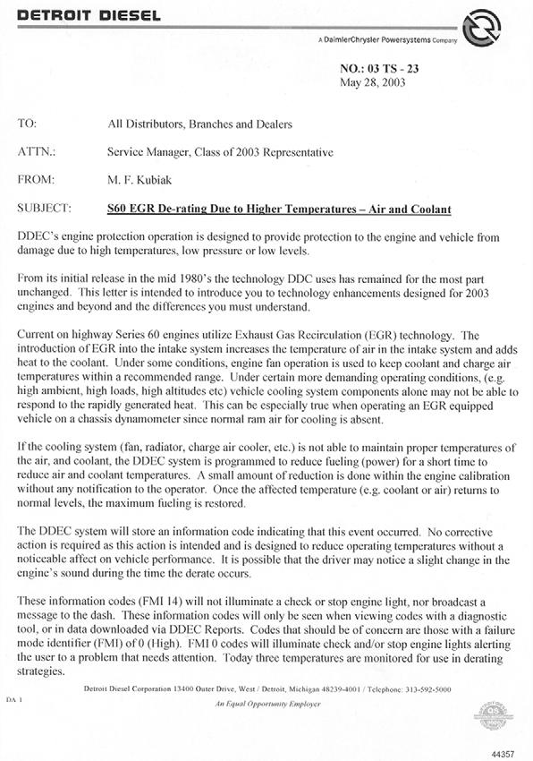
179
180
181
182

183
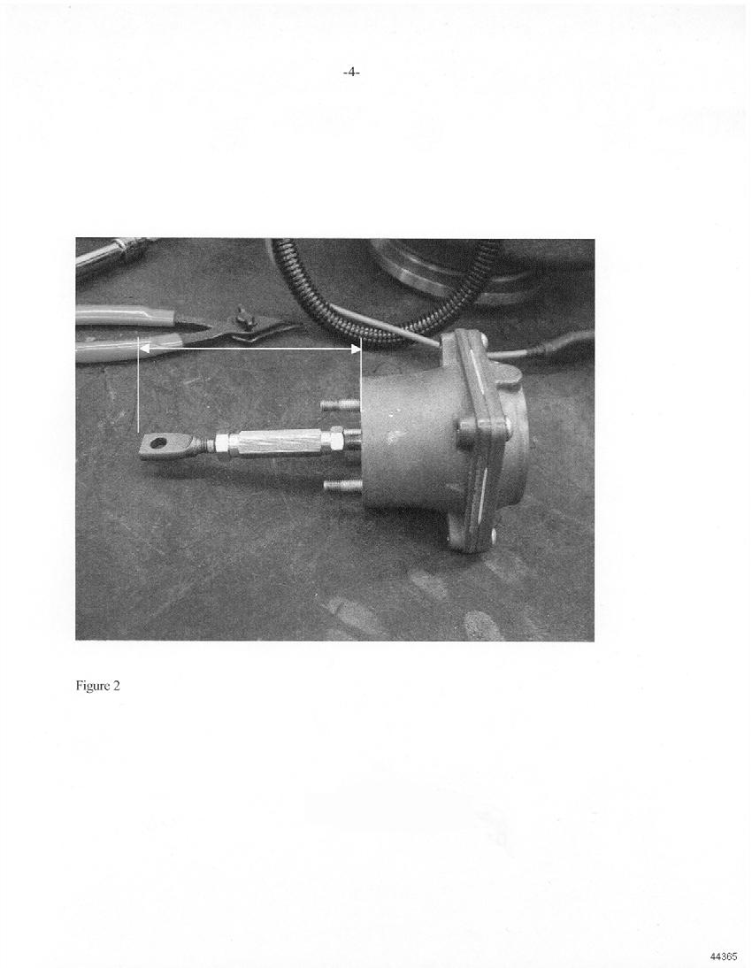
184
185
186
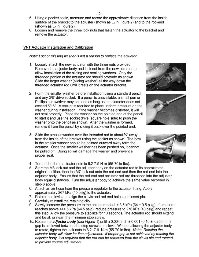
187
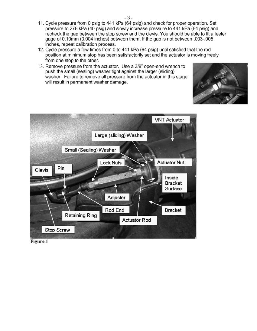
188
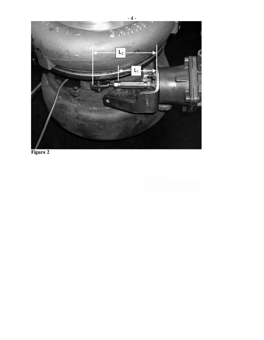
189
This document, and more, is available for download from Martin's Marine Engineering Page -
 ATTENTION The information in this document is accurate as of April 2004 and is subject to change without notice. This manual is to be used in conjunction with the DDEC III/IV Single ECM Troubleshooting
DETROIT DIESEL FAULT CODES.
 DETROIT DIESEL FAULT CODES https://truck-manuals.jimdo.com/detroit-diesel-fault-codes/ Code Description DDEC V Circuit 11 P 187 4 Chain PTO. Short circuit in the power 11 P 187 7 control system PTO wrong
Variable Nozzle Turbocharger (VNT)
") Variable Nozzle Turbocharger (VNT) Figure 2-5 VNT Turbocharger Figure 2-6 Cut Away View of the Vanes The results of being able to adjust like this are as follow. See Figure 2-5 and see Figure 2-6. Enhanced
Variable Nozzle Turbocharger (VNT) Figure 2-5 VNT Turbocharger Figure 2-6 Cut Away View of the Vanes The results of being able to adjust like this are as follow. See Figure 2-5 and see Figure 2-6. Enhanced
2 OPERATION 2.1 DDEC BENEFITS FEATURES DDEC SYSTEM--HOW IT WORKS DDEC RELATED PUBLICATIONS...
 2 OPERATION Section Page 2.1 DDEC BENEFITS... 2-3 2.2 FEATURES... 2-4 2.3 DDEC SYSTEM--HOW IT WORKS... 2-5 2.4 DDEC RELATED PUBLICATIONS... 2-23 (Rev. 2/03) All information subject to change without notice.
77 FLASH CODE 77 - EXHAUST BACK PRESSURE FAULT AND SEVERAL INFORMATION CODES
 77 FLASH CODE 77 - EXHAUST BACK PRESSURE FAULT AND SEVERAL INFORMATION CODES Section Page 77.1 DESCRIPTION OF FLASH CODE 77... 77-3 77.2 SAE J1587 EQUIVALENT CODE FOR FLASH CODE 77... 77-3 77.3 TROUBLESHOOTING
NUMBER: 1 SECM 03 S.M. REF.: Listed in Table 1 ENGINE: ALL DATE: February 2003
 NUMBER: 1 SECM 03 S.M. REF.: Listed in Table 1 ENGINE: ALL DATE: February 2003 SUBJECT: UPDATES FOR TROUBLESHOOTING SERIES 60 AND SERIES 50 EGR RELATED CODES AND FAULTS INTRODUCTION The Series 60 engine
Troubleshooting guide for poor acceleration, black smoke, and flash code 39, SID 147, FMI 7 or 2
 No.: 09 TS-17Rev2 November 25, 2009 TO: FROM: Service Locations Technical Support Development SUBJECT: EPA04 DDEC V Series 60 Engines Turbocharger Performance Diagnostic Checklist NOTE: This document supersedes
ISC, QSC8.3, and ISL (FIS )
") Fault Information System... 1 FIS Usage Recommendations... 2 FIS Usage Recommendations... 2 Diagnostic Methods... 9 Troubleshooting Fault Codes... 9 Information Fault Codes... 3 (fc211) Fault Code 211...
Fault Information System... 1 FIS Usage Recommendations... 2 FIS Usage Recommendations... 2 Diagnostic Methods... 9 Troubleshooting Fault Codes... 9 Information Fault Codes... 3 (fc211) Fault Code 211...
Section 10 Chapter 7
 Section 10 Chapter 7 24 Valve, 8.3 Liter Engine Troubleshooting Symptoms Identification Note: All coding used in the 8.3 Liter and 9 Liter engine manuals are Cummins engine codes. These engine codes have
Additions, Revisions, or Updates
 1 9 14-14 SUBJECT DATE SPN 3563 (MCM) (GHG14) September 2014 Additions, Revisions, or Updates Publication Number / Title Platform Section Title Change DDC-SVC-MAN-0084 GHG14 DD Platform SPN 3563/FMI 21
NUMBER: S.M. REF.: Listed in Table ENGINE: EPA07 MBE 4000 DATE: April 2009
 NUMBER: 4 11 09 S.M. REF.: Listed in Table ENGINE: EPA07 MBE 4000 DATE: April 2009 SUBJECT: SPN 2631 ADDITIONS, REVISIONS, OR UPDATES Publication Number Platform Section Title Change Page Number(s) DDC-SVC-MAN-0010
DASH RETRIEVED FAULT CODES C ONVENTIONAL FS65 SAF T LINER C2, C2E H YBRID SAF T LINER HDX, HD, ER SAF T LINER EF, EFX A LL Y EARS
 DASH RETRIEVED FAULT CODES C ONVENTIONAL FS65 SAF T LINER C2, C2E H YBRID SAF T LINER HD, HD, ER SAF T LINER EF, EF A LL Y EARS PAGE INTENTIONALLY LEFT BLANK TABLE OF CONTENTS EARLY PRODUCTS: J1587/J1708
Trucks. Group 28 MID 128 Fault Code Guide 2007 Emissions VN, VHD VERSION2, VT PV
 Service Manual Trucks MID 128 Fault Code Guide 2007 Emissions VN, VHD VERSION2, VT PV776-20184635 Foreword The descriptions and service procedures contained in this manual are based on designs and methods
NUMBER: S.M. REF.: Listed in Table ENGINE: EPA07 MBE 4000 DATE: September 2009
 NUMBER: 9 3 09 S.M. REF.: Listed in Table ENGINE: EPA07 MBE 4000 DATE: September 2009 SUBJECT: TURBOCHARGER WASTEGATE ADDITIONS, REVISIONS, OR UPDATES Publication Number Platform Section Title Change Page
EMISSION CONTROL SYSTEM
 XJ EMISSION CONTROL SYSTEM 25-1 EMISSION CONTROL SYSTEM TABLE OF CONTENTS ON-BOARD DIAGNOSTICS 2.5L DIESEL ENGINE... 1 EXHAUST EMISSION CONTROLS 2.5L DIESEL ENGINE... 6 ON-BOARD DIAGNOSTICS 2.5L DIESEL
DIAGNOSTIC REPORT. Vehicle Components. Vehicle Key Data Points
 Page 1 of 5 Vehicle Components Engine Cummins 15.0L ISX2 79312438 03684275 05026491 052311201001 08000091 B0 BAC High/Low Speed Brakes Bendix EC-60 Standard ABS N/A BB40905 High/Low Speed Vehicle Key Data
EMISSION CONTROL SYSTEM
 XJ EMISSION CONTROL SYSTEM 25-1 EMISSION CONTROL SYSTEM CONTENTS EXHAUST EMISSION CONTROLS 2.5L DIESEL ENGINE... 6 ON-BOARD DIAGNOSTICS 2.5L DIESEL ENGINE... 1 ON-BOARD DIAGNOSTICS 2.5L DIESEL ENGINE INDEX
CUMMINS ENGINE DIAGNOSTIC CODES
 ENGINE DIAGNOSTICS GROUP 105 CUMMINS ENGINE DIAGNOSTIC CODES 1 INTRODUCTION... 1 2 TROUBLESHOOTING CODES... 1 1 INTRODUCTION. This group provides information on the engine fault codes that could potentially
G - TESTS W/CODES - 2.2L
 G - TESTS W/CODES - 2.2L 1994 Toyota Celica 1994 ENGINE PERFORMANCE Toyota 2.2L Self-Diagnostics Celica INTRODUCTION If no faults were found while performing F - BASIC TESTING, proceed with self-diagnostics.
Additions, Revisions, or Updates
 1 10 26-13 SUBJECT DATE SPN 3216/FMI 16 and 18 October 2013 Additions, Revisions, or Updates Publication Number / Title Platform Section Title Change DDC-SVC-MAN-0084 GHG14 DD Platform SPN 3216/FMI 16
Additions, Revisions, or Updates
 4 68-12 1 4 68-12 SUBJECT DATE SPN 5018/FMI 18 - GHG14 September 2012 Additions, Revisions, or Updates Publication Number / Title Platform Section Title Change DDC-SVC-MAN-0084 DD Platform SPN 5018/FMI
Additions, Revisions, or Updates
 01 04-15 1 01 04-15 SUBJECT DATE SPN 3464/ FMI 16, 18 (MCM) (GHG14) January 2015 Additions, Revisions, or Updates Publication Number / Title Platform Section Title Change DDC-SVC-MAN-0084 DD Platform SPN
Additions, Revisions, or Updates
 1 11 19-13 SUBJECT DATE SPN 3216/FMI 2, 18 GHG14 (MCM2.1) November 2013 Additions, Revisions, or Updates Publication Number / Title Platform Section Title Change SPN 3216/FMI 2 DDC-SVC-MAN-0084 GHG14 DD
5 FEATURES DDEC FOR MBE900 AND MBE4000
 DDEC FOR MBE900 AND MBE4000 5 FEATURES Section Page 5.1 ANTI-LOCK BRAKE/AUTOMATIC TRACTION CONTROL SYSTEMS.. 5-5 5.2 COLD START... 5-7 5.3 CRUISE CONTROL... 5-11 5.4 DIAGNOSTICS... 5-19 5.5 DUAL SPEED
Additions, Revisions, or Updates
 1 9 19-13 SUBJECT DATE SPN 102/FMI 18 - GHG14 MCM2.1 October 2013 Additions, Revisions, or Updates Publication Number / Title Platform Section Title Change DDC-SVC-MAN-0084 DD Platform SPN 102/FMI 18 Complete
NUMBER: S.M. REF.: Listed in Table ENGINE: EPA07 Series 60 DATE: April 2009
 NUMBER: 4 7 09 S.M. REF.: Listed in Table ENGINE: EPA07 Series 60 DATE: April 2009 SUBJECT: SPN 27 ADDITIONS, REVISIONS, OR UPDATES Publication Number Platform Section Title Change Page Number(s) DDC-SVC-MAN-0009
NUMBER: S.M. REF.: Listed in Table ENGINE: EPA07 Series 60 DATE: October 2010
 NUMBER:10 02 10 S.M. REF.: Listed in Table ENGINE: EPA07 Series 60 DATE: October 2010 SUBJECT: DOUBLEHYSTERESISTEST ADDITIONS, REVISIONS, OR UPDATES Publication Number Platform Section Title Change Page
#97-T-20A: MIL (Service Engine Soon Telltale Lamp) On and EGR DTCs P0401, P0404, P0405, P1404 and/or P1406 in PCM Memory - (Jan 6, 2003)
 On and EGR DTCs P0401, P0404, P0405, P1404 and/or P1406 in PCM Memory - (Jan 6, 2003)") #97-T-20A: MIL (Service Engine Soon Telltale Lamp) On and EGR DTCs P0401, P0404, P0405, P1404 and/or P1406 in PCM Memory - (Jan 6, 2003) Subject: Malfunction Indicator Lamp (SERVICE ENGINE SOON Telltale
#97-T-20A: MIL (Service Engine Soon Telltale Lamp) On and EGR DTCs P0401, P0404, P0405, P1404 and/or P1406 in PCM Memory - (Jan 6, 2003) Subject: Malfunction Indicator Lamp (SERVICE ENGINE SOON Telltale
SYTY Trouble Code: ALDL INFORMATION
 SYTY Trouble Code: ALDL INFORMATION A -- Ground G -- Fuel Pump B -- Diagnostic Terminal H -- Brake Sense Speed Input F -- TCC M -- Serial Data (special tool needed - Do Not Use) For ECM Trouble Codes,
EGR System, Design and Function. This information covers design and function of the Exhaust Gas Recirculation (EGR) system on a Volvo D16F engine.
 system on a Volvo D16F engine.") Volvo Trucks North America Greensboro, NC USA DService Bulletin Trucks Date Group No. Page 12.2006 254 59 1(6) EGR System Design and Function D16F EGR System, Design and Function W2005836 This information
Volvo Trucks North America Greensboro, NC USA DService Bulletin Trucks Date Group No. Page 12.2006 254 59 1(6) EGR System Design and Function D16F EGR System, Design and Function W2005836 This information
FAULT CODE 692 Turbocharger Number 1 Compressor Inlet Temperature Sensor Circuit - Voltage Below Normal or Shorted to Low Source
 Page 1 of 14 FAULT CODE Turbocharger Number 1 Compressor Inlet Temperature Sensor Circuit - Voltage Below Normal or Shorted to Low Source View Related Topic Overview CODE REASON EFFECT : PID: SPN: 1172
NUMBER: 08 DDEC VI 10 S.M. REF.: 92 ENGINE: EPA07 Series 60 DATE: March 2008
 NUMBER: 08 DDEC VI 10 S.M. REF.: 92 ENGINE: EPA07 Series 60 DATE: March 2008 SUBJECT: SPN 2659 PUBLICATION: DDC-SVC-MAN-0009 (6SE567) Section SPN 2659/FMI 0, refer to section 92.1 SPN 2659/FMI 17, refer
Alternator Ground Check Verify Repairs
 DDEC III/IV SINGLE ECM TROUBLESHOOTING GUIDE 16.3.6 Alternator Ground Check Perform the following steps to check the alternator ground. 1. Connect all connectors. 2. Remove alternator belt or disable alternator
NUMBER: S.M. REF.: Listed in Table ENGINE: EPA07 MBE 4000 DATE: May 2013 SUBJECT: SPN 2631/FMI 2 ADDITIONS, REVISIONS, OR UPDATES
 NUMBER: 5 26 13 S.M. REF.: Listed in Table ENGINE: EPA07 MBE 4000 DATE: May 2013 SUBJECT: SPN 2631/FMI 2 ADDITIONS, REVISIONS, OR UPDATES Publication Number Platform Section Title Change DDC-SVC-MAN-0010
Powertrain DTC Summaries EOBD
 Powertrain DTC Summaries Quick Reference Diagnostic Guide Jaguar X-TYPE 2.0 L 2002.25 Model Year Refer to page 2 for important information regarding the use of Powertrain DTC Summaries. Jaguar X-TYPE 2.0
Vehicle Components. Vehicle Key Data Points
 VIN Vehicle Make Model Model Year 2HSCUAPR48C687071 International Prostar 2008 Vehicle s Serial Number Software Version Network Engine Cummins 15.0L ISX1 79277503 03684275 05000708 072209134739 08000062
NUMBER: S.M. REF.: Listed in Table ENGINE: EPA07 Series 60 DATE: October 2012 SUBJECT: REFERENCES TO THE TURBOCHARGER PURGE ROUTINE
 NUMBER: 10 01 12 S.M. REF.: Listed in Table ENGINE: EPA07 Series 60 DATE: October 2012 SUBJECT: REFERENCES TO THE TURBOCHARGER PURGE ROUTINE ADDITIONS, REVISIONS, OR UPDATES Publication Number Platform
Oregon Fuel Injection
 2001 2006 Dodge Mercedes - Freightliner Sprinter Diagnostics In order to do proper diagnostics you will need a scan tool and some special tools available from Mopar Special Tools http://mopar.snapon.com.
Service Bulletin No. 2969C
 MODEL TYPE SECTION/GROUP DATE E / J Series Coaches Service Information 8--Engine April 13, 2009 SUBJECT CUMMINS ISM DIESEL EPA ENGINES CONDITIONS Service Information Only THIS BULLETIN SUPERCEDES FIELD
DIAGNOSTIC REPORT. Vehicle Components. Engine Cummins 15.0L ISX B0 BAC Brakes Bendix EC-60 Advanced ABS P
 Page 1 of 5 Vehicle s Serial Number Software Version Network Engine Cummins 15.0L ISX1 79367509 03684275 05069157 012610210802 08000065 B0 BAC Brakes Bendix EC-60 Advanced ABS P230800301 BB40999 BB41033,
H - TESTS W/O CODES Volvo 960 INTRODUCTION SYMPTOMS SYMPTOM DIAGNOSIS ENGINE PERFORMANCE Volvo Trouble Shooting - No Codes
 H - TESTS W/O CODES 1994 Volvo 960 1994 ENGINE PERFORMANCE Volvo Trouble Shooting - No Codes Volvo; 850, 940, 960 INTRODUCTION Before diagnosing symptoms or intermittent faults, perform steps in appropriate
Additions, Revisions, or Updates
 1 8 03-13 SUBJECT DATE SPN 51/FMI 2, 10, 18 August 2013 Additions, Revisions, or Updates Publication Number / Title Platform Section Title Change DD Platform SPN 51/FMI 2 All Years Most steps have been
Additions, Revisions, or Updates
 1 9 04-11 SUBJECT DATE SPN 3250 / FMI 16 DOC Outlet Temperature High August 2011 Additions, Revisions, or Updates Publication Number / Title Platform Section Title Change DDC-SVC-MAN-0084 EPA07 DD13/DD15
The Aftertreatment System Technician's Guide (7SE63) was revised to include three new procedures.
 was revised to include three new procedures.") NUMBER: 07 ATS 3 S.M. REF.: Listed in Table 1 ENGINE: ATS DATE: December 2007 SUBJECT: ADDITIONAL PROCEDURES WERE ADDED TO AFTERTREATMENT SYSTEM PUBLICATION: 7SE63 The Aftertreatment System Technician's
NUMBER: 07 ATS 3 S.M. REF.: Listed in Table 1 ENGINE: ATS DATE: December 2007 SUBJECT: ADDITIONAL PROCEDURES WERE ADDED TO AFTERTREATMENT SYSTEM PUBLICATION: 7SE63 The Aftertreatment System Technician's
SPN 4364/FMI 17 - GHG17 SPN /FMI 16 - GHG17 SPN /FMI 14 - GHG17 SPN 3216/FMI 16 - GHG17 SPN 3216/FMI 18 - GHG17 SPN 3217/FMI 2 - GHG17
 11 29-16 1 11 29-16 SUBJECT SPN 4364 (ACM) (GHG17) SPN 520371 (ACM) (GHG17) SPN 520372 (ACM) (GHG17) SPN 3216 (ACM) (GHG17) SPN 3217 (ACM) (GHG17) SPN 3226 (ACM) (GHG17) SPN 3227 (ACM) (GHG17) Diagnostic
2002 Buick Rendezvous - AWD
 2002 Buick Rendezvous - AWD DTC P0410 Description The control module activates the secondary air injection (AIR) system by grounding both the pump relay and the vacuum control solenoid control circuits.
Powertrain Control Software
 2007 PCED On Board Diagnostics SECTION 1: Description and Operation Procedure revision date: 03/29/2006 Powertrain Control Software Computer Controlled Shutdown The powertrain control module (PCM) controls
DIAGNOSTIC REPORT. Vehicle Components. Speed Brakes Bendix EC-60 Advanced ABS BB40904, L
 Page 1 of 6 Vehicle s Serial Number Software Version Network Engine Cummins 15.0L ISX1 79239088 03684275 03003605 030207213932 07000020 B0 BAC High/Low Speed Transmission Eaton RTLO_xx913E s0653423 5569884
Additions, Revisions, or Updates
 1 12 02-12 SUBJECT DATE Test E - Three-Filter Fuel System December 2012 Additions, Revisions, or Updates Publication Number / Title Platform Section Title Change DDC-SVC-MAN-0084 DD Platform Test E - Three-Filter
Service Bulletin Buses
 Prevost Saint-Nicolas, Quebec, Canada Service Bulletin Buses Date Group No. Release Page 6.2010 364 00 1(12) Vehicle Electronic Control Unit (VECU) MID 144, Diagnostic Trouble Code (DTC), Guide Vehicle
DTC P0171, P0172, P0174, or P0175
 Page 1 of 6 2009 Pontiac G8 G8 Service Manual Document ID: 2076050 DTC P0171, P0172, P0174, or P0175 Diagnostic Instructions Perform the Diagnostic System Check - Vehicle prior to using this diagnostic
DIAGNOSTIC REPORT. Vehicle Components. Vehicle Key Data Points
 Page 1 of 5 Vehicle Components Engine Cummins 15.0L ISX3 79270697 03684275 04017048 030711195725 08000084 B0 BAC High/Low Speed Brakes Bendix EC-60 Premium ABS N/A BB40970 High/Low Speed Vehicle Key Data
Alternative Fuel Engine Control Unit
 1999 Chevrolet/Geo Cavalier (CNG) Alternative Fuel Engine Control Unit Table 1: AF ECU Function Parameters The (AF ECU) controls alternative fuel engine operation. The control unit monitors various engine
NUMBER: S.M. REF.: Listed in Table 1 ENGINE: DD13 DATE: July 2009
 NUMBER: 7 4 09 S.M. REF.: Listed in Table 1 ENGINE: DD13 DATE: July 2009 SUBJECT: EXHAUST GAS RECIRCULATION COOLER WATER MANIFOLD ASSEMBLY ADDITIONS, REVISIONS, OR UPDATES Publication Number Platform Section
CUMMINS FAULT CODE: 1239 PID: SPN: 2623 FMI: 3/3 LAMP: AMBER
 CUMMINS ACCELERATOR PEDAL OR LEVER POSITION SENSOR 2 CIRCUIT - VOLTAGE ABOVE NORMAL OR HORTED TO HIGH SOURCE FAULT CODE: 1239 PID: SPN: 2623 FMI: 3/3 LAMP: AMBER DESCRIPTION ISX and ISM Accelerator Pedal
Study Guide MaxxForce TM 5 Engine Update TMT
 A N AV I S TA R C O M PA N Y MaxxForce TM 5 Engine Update Study Guide TMT-120710 Study Guide MaxxForce TM 5 Engine Update TMT-120710 2007 International Truck and Engine Corporation 4201 Winfield Road,
3 HARDWARE AND WIRING
 DDEC IV ON-HIGHWAY - EGR APPLICATION AND INSTALLATION 3 HARDWARE AND WIRING Section Page 3.1 SUPPLIED HARDWARE... 3-3 3.2 ELECTRONIC CONTROL MODULE... 3-5 3.3 ENGINE SENSOR HARNESS... 3-9 3.4 VEHICLE INTERFACE
MULTIPOINT FUEL INJECTION (MPI) <4G9>
 <4G9>") MULTIPOINT FUEL INJECTION (MPI) 13C-1 MULTIPOINT FUEL INJECTION (MPI) CONTENTS GENERAL................................. 2 Outline of Changes............................ 2 GENERAL INFORMATION...................
MULTIPOINT FUEL INJECTION (MPI) 13C-1 MULTIPOINT FUEL INJECTION (MPI) CONTENTS GENERAL................................. 2 Outline of Changes............................ 2 GENERAL INFORMATION...................
MAN TRUCK FAULT CODES ENGINE CONTROL UNITS (EDC7) https://truck-manuals.jimdo.com/man-fault-codes/?logout=1
 https://truck-manuals.jimdo.com/man-fault-codes/?logout=1") MAN TRUCK FAULT CODES ENGINE CONTROL UNITS (EDC7) https://truck-manuals.jimdo.com/man-fault-codes/?logout=1 Code (SPN) Description Reason, verification and system response. 81 exhaust pressure difference.
MAN TRUCK FAULT CODES ENGINE CONTROL UNITS (EDC7) https://truck-manuals.jimdo.com/man-fault-codes/?logout=1 Code (SPN) Description Reason, verification and system response. 81 exhaust pressure difference.
Fuel Metering System Component Description
 1999 Chevrolet/Geo Tahoe - 4WD Fuel Metering System Component Description Purpose The function of the fuel metering system is to deliver the correct amount of fuel to the engine under all operating conditions.
THE witech SOFTWARE LEVEL MUST BE AT RELEASE **15.04** OR HIGHER TO PERFORM THIS PROCEDURE.
 2014 RAM 3500 HD 6.7L Eng Big Horn FLASH: 6.7L DIAGNOSTIC AND SYSTEM IMPROVEMENTS TECHNICAL SERVICE BULLETIN Reference Number(s): 18-045-15, Date of Issue: May 20, 2015 CHRYSLER: 2014 Ram 2500 Pick Up
1 of :23
 1 of 8 2013.02.09 03:23 Published: 08-Jun-2012 Electronic Engine Controls - TDV8 3.6L Diesel - Electronic Engine Controls 3.6L (TdV8) Diesel Diagnosis and Testing Overview This section covers the components
UENR4504 January Troubleshooting. 854F-E34TA Industrial Engine. JU (Engine) This document has been printed from SPI2.
 This document has been printed from SPI2.") UENR4504 January 2015 Troubleshooting 854F-E34TA Industrial Engine JU (Engine) Important Safety Information Most accidents that involve product operation, maintenance and repair are caused by failure to
UENR4504 January 2015 Troubleshooting 854F-E34TA Industrial Engine JU (Engine) Important Safety Information Most accidents that involve product operation, maintenance and repair are caused by failure to
Subject Underhood G System Error Codes and Symptoms System or Parts affected
 System or Parts affected Index Underhood70G (V90Gxxx) System or Parts affected... 1 Overview... 1 Identifying your System... 1 Retrieving Logged Error Messages... 1 Error Messages... 3 Error Message Table...
E - THEORY/OPERATION - TURBO
 E - THEORY/OPERATION - TURBO 1995 Volvo 850 1995 ENGINE PERFORMANCE Volvo - Theory & Operation 850 - Turbo INTRODUCTION This article covers basic description and operation of engine performance-related
Diagnostic Trouble Code (DTC) Root Cause. for Omnitek ECM 64A/66A/88A. & Remedial Action
 Root Cause. for Omnitek ECM 64A/66A/88A. & Remedial Action") Diagnostic Trouble Code (DTC) Root Cause & Remedial Action for Omnitek ECM 64A/66A/88A Omnitek Engineering Corp. 1945 S Rancho Santa Fe Rd. San Marcos, CA 92078 Tel. 760-591-0089 - Fax. 760-591-0880 -
Diagnostic Trouble Code (DTC) Root Cause & Remedial Action for Omnitek ECM 64A/66A/88A Omnitek Engineering Corp. 1945 S Rancho Santa Fe Rd. San Marcos, CA 92078 Tel. 760-591-0089 - Fax. 760-591-0880 -
2007 MaxxForce TM 11 and MaxxForce 13 Engine Diagnostics
 A N AV I S TA R C O M PA N Y 2007 MaxxForce TM 11 and MaxxForce 13 Engine Diagnostics Study Guide TMT-120802 Study Guide MaxxForce TM 11 and MaxxForce 13 Engine Systems TMT-120802 2008 International Truck
INTAKE AND EXHAUST GROUP CONTENTS CHARGE AIR COOLER <2.0L ENGINE> GENERAL DESCRIPTION SERVICE SPECIFICATIONS...
 15-1 GROUP 15 INTAKE AND EXHAUST CONTENTS GENERAL DESCRIPTION 15-2 SERVICE SPECIFICATIONS 15-2 DIAGNOSIS 15-2 INTRODUCTION 15-2 TROUBLESHOOTING STRATEGY 15-2 SYMPTOM CHART 15-2 SYMPTOM PROCEDURES 15-3
Powertrain DTC Summaries OBD II
 Powertrain DTC Summaries Quick Reference Diagnostic Guide Jaguar X-TYPE 2.5L and 3.0L 2002 Model Year Revised January, 2002: P0706, P0731, P0732, P0733, P0734, P0735, P0740, P1780 POSSIBLE CAUSES Revised
Service Bulletin No. 2965C
 Service Bulletin No. 2965C MODEL TYPE SECTION/GROUP DATE E / J Series Coaches Service Information 8--Engine April 13, 2009 SUBJECT DDC S60 2007 ENGINES CONDITIONS Service Information Only THIS BULLETIN
DTC P0172 Fuel Trim System Rich
 Page 1 of 6 1997 Chevrolet Cavalier Cavalier, Sunfire (VIN J) Service Manual Document ID: 47788 DTC P0172 Fuel Trim System Rich System Description A Closed Loop air/fuel metering system is used to provide
SECTION 5 DIAGNOSTIC TROUBLE CODES (DTC)
") 5 1. DTC MEMORY SECTION 5 Diagnostic Trouble Codes (DTCs) are logged in a list in TCM memory. The DTCs contained in the list have information recorded as shown in Table 5 1 (DTC example). The TCM is capable
5 1. DTC MEMORY SECTION 5 Diagnostic Trouble Codes (DTCs) are logged in a list in TCM memory. The DTCs contained in the list have information recorded as shown in Table 5 1 (DTC example). The TCM is capable
Powertrain DTC Summaries EOBD
 Powertrain DTC Summaries Quick Reference Diagnostic Guide Jaguar S-TYPE V6, V8 N/A and V8 SC 2002.5 Model Year Refer to pages 2 9 for important information regarding the use of Powertrain DTC Summaries.
81 FLASH CODE 81 OIL LEVEL, EXHAUST TEMP, EGR TEMP OR EGR DELTA-PRESSURE, CIRCUIT FAILED HIGH
 81 FLASH CODE 81 OIL LEVEL, EXHAUST TEMP, EGR TEMP OR EGR DELTA-PRESSURE, CIRCUIT FAILED HIGH Section Page 81.1 DESCRIPTION OF FLASH CODE 81... 81-3 81.2 SAE J1587 EQUIVALENT CODE FOR FLASH CODE 81...
82 FLASH CODE 82 OIL LEVEL, EXHAUST TEMP, EGR TEMP OR EGR DELTA-PRESSURE, CIRCUIT FAILED LOW
 82 FLASH CODE 82 OIL LEVEL, EXHAUST TEMP, EGR TEMP OR EGR DELTA-PRESSURE, CIRCUIT FAILED LOW Section Page 82.1 DESCRIPTION OF FLASH CODE 82... 82-3 82.2 SAE J1587 EQUIVALENT CODE FOR FLASH CODE 82... 82-3
FAULT CODE 432 (SSS) Accelerator Pedal Circuit
 Accelerator Pedal Circuit") FAULT CODE 432 (SSS) Accelerator Pedal Circuit Overview CODE REASON EFFECT Fault Code: 432 PID: P091 SPN: 91 FMI: 13 LAMP: Red SRT: 00-612 No voltage detected at idle validation on-idle signal pin 6 of
FAULT CODE 432 (SSS) Accelerator Pedal Circuit Overview CODE REASON EFFECT Fault Code: 432 PID: P091 SPN: 91 FMI: 13 LAMP: Red SRT: 00-612 No voltage detected at idle validation on-idle signal pin 6 of
TMT121336EN 8355 R EPA, 2013 N13 Engine Aftertreatment System Overview for Technicians Study Guide
 TMT121336EN 8355 R1 2010 EPA, 2013 N13 Engine Aftertreatment System Overview for Technicians Study Guide 2010 EPA, 2013 N13 Engine Aftertreatment System STUDY GUIDE 2014 Navistar, Inc. 2701 Navistar Drive,
OBD-II Diagnostic Powertrain (P) Trouble Codes
 Trouble Codes") OBD-II Diagnostic Powertrain (P) Trouble Codes Please use our new & improved search engine to find information on your trouble codes. Search Now! This list contains standard diagnostic trouble codes (DTC
OBD-II Diagnostic Powertrain (P) Trouble Codes Please use our new & improved search engine to find information on your trouble codes. Search Now! This list contains standard diagnostic trouble codes (DTC
Air Management System Components
 AIR M anagement Sys tem Air Management System Components Air Management System Features Series Sequential The series sequential turbocharger is a low pressure/high pressure design working in series with
Diagnostic Trouble Code (DTC) List - Vehicle
 List - Vehicle") Document ID# 850406 2002 Pontiac Firebird Diagnostic Trouble Code (DTC) List - Vehicle DTC DTC 021 and/or 031 DTC 022 and/or 032 DTC 023 or 033 DTC 24/34 DTC 025 and/or 035 DTC 041 DTC 042 DTC 043 DTC
Document ID# 850406 2002 Pontiac Firebird Diagnostic Trouble Code (DTC) List - Vehicle DTC DTC 021 and/or 031 DTC 022 and/or 032 DTC 023 or 033 DTC 24/34 DTC 025 and/or 035 DTC 041 DTC 042 DTC 043 DTC
DTC P0420 or P0430. Circuit Description. DTC Descriptors. Conditions for Running the DTC
 Page 1 of 5 2005 Cadillac STS STS (VIN D) Service Manual Engine Engine Controls - 4.6L (LH2) Diagnostic Information and Procedures DTC P0420 or P0430 Circuit Description A three-way catalytic converter
5 DDEC FEATURES DDEC IV APPLICATION AND INSTALLATION MANUAL
 DDEC IV APPLICATION AND INSTALLATION MANUAL 5 DDEC FEATURES Section Page 5.1 AIR COMPRESSOR CONTROL... 5-3 5.2 ANTI-LOCK BRAKE SYSTEMS... 5-9 5.3 CRUISE CONTROL... 5-13 5.4 CRUISE CONTROL FOR DRILLING/PUMPING
01 02B ON-BOARD DIAGNOSTIC [ENGINE CONTROL SYSTEM (FS)]
![01 02B ON-BOARD DIAGNOSTIC [ENGINE CONTROL SYSTEM (FS)]](/thumbs/80/80600627.jpg "01 02B ON-BOARD DIAGNOSTIC [ENGINE CONTROL SYSTEM (FS)]") ON-BOARD DIAGNOSTIC [ENGINE CONTROL SYSTEM (FS)] CONTROL SYSTEM WIRING DIAGRAM [FS]............................ 2 CONTROL SYSTEM DEVICE AND CONTROL RELATIONSHIP CHART [FS]........ 4 Engine Control System............
ON-BOARD DIAGNOSTIC [ENGINE CONTROL SYSTEM (FS)] CONTROL SYSTEM WIRING DIAGRAM [FS]............................ 2 CONTROL SYSTEM DEVICE AND CONTROL RELATIONSHIP CHART [FS]........ 4 Engine Control System............
2010 EPA 2013 HD-OBD N9 and N10 with SCR Diagnostics for Technicians. Study Guide. Course Code: 8448
 2010 EPA 2013 HD-OBD N9 and N10 with SCR Diagnostics for Technicians Study Guide Course Code: 8448 1 2010 EPA 2013 HD-OBD N9 and N10 with SCR Diagnostics for technicians Study Guide 2014 Navistar, Inc.
Diagnostic Trouble Code (DTC) Guide for Omnitek ECM 64A/66A/88A
 Guide for Omnitek ECM 64A/66A/88A") Diagnostic Trouble Code (DTC) Guide for Omnitek ECM 64A/66A/88A Omnitek Engineering Corp. 1333 Keystone Way, #101 Vista, CA 92081 Tel. 760-591-0089 - Fax. 760-591-0880 - Copyright 2006 Omnitek Engineering,
Diagnostic Trouble Code (DTC) Guide for Omnitek ECM 64A/66A/88A Omnitek Engineering Corp. 1333 Keystone Way, #101 Vista, CA 92081 Tel. 760-591-0089 - Fax. 760-591-0880 - Copyright 2006 Omnitek Engineering,
Dealing with customer concerns related to electronic throttle bodies By: Bernie Thompson
 Dealing with customer concerns related to electronic throttle bodies By: Bernie Thompson In order to regulate the power produced from the gasoline internal combustion engine (ICE), a restriction is used
SAFETY PRECAUTIONS BEFORE YOU BEGIN TECHNICAL SUPPORT ABOUT THIS MANUAL OPTIMIZED IDLE USER MANUAL
 OPTIMIZED IDLE USER MANUAL BEFORE YOU BEGIN The information in this manual is subject to change without notice. Although every effort was made to ensure that the most current information is made available
EMISSION CONTROL (AUX. EMISSION CONTROL DEVICES) H4DOTC
 H4DOTC") EMISSION CONTROL (AUX. EMISSION CONTROL DEVICES) H4DOTC SYSTEM OVERVIEW 1. System Overview There are three emission control systems, which are as follows: Crankcase emission control system Exhaust emission
EMISSION CONTROL (AUX. EMISSION CONTROL DEVICES) H4DOTC SYSTEM OVERVIEW 1. System Overview There are three emission control systems, which are as follows: Crankcase emission control system Exhaust emission
13A-1 FUEL CONTENTS MULTIPOINT FUEL INJECTION (MPI) FUEL SUPPLY... 13B
 FUEL SUPPLY... 13B") 13A-1 FUEL CONTENTS MULTIPOINT FUEL INJECTION (MPI)... 13A FUEL SUPPLY... 13B 13A-2 MULTIPOINT FUEL INJECTION (MPI) CONTENTS GENERAL INFORMATION... 3 SERVICE SPECIFICATIONS... 6 SEALANT... 6 SPECIAL TOOLS...
13A-1 FUEL CONTENTS MULTIPOINT FUEL INJECTION (MPI)... 13A FUEL SUPPLY... 13B 13A-2 MULTIPOINT FUEL INJECTION (MPI) CONTENTS GENERAL INFORMATION... 3 SERVICE SPECIFICATIONS... 6 SEALANT... 6 SPECIAL TOOLS...
Injector Solenoid - Test
 Injector Solenoid - Test System Operation Description: Use this procedure to troubleshoot the electrical system if a problem is suspected with the injectors or if any one of the diagnostic codes in Table
G - TESTS W/CODES Nissan 240SX * PLEASE READ THIS FIRST * INTRODUCTION SELF-DIAGNOSTIC SYSTEM DESCRIPTION HARD FAILURES INTERMITTENT FAILURES
 G - TESTS W/CODES 1990 Nissan 240SX 1990 ENGINE PERFORMANCE Self-Diagnostics Nissan 240SX and Axxess * PLEASE READ THIS FIRST * NOTE: This article has been revised according to Technical Service Bulletin
SPN 4364 (ACM)(EPA10); SPN 4364 (ACM)(GHG14) January Publication Number / Title Platform Section Title Change SPN 4364/FMI 18 - EPA10
(EPA10); SPN 4364 (ACM)(GHG14) January Publication Number / Title Platform Section Title Change SPN 4364/FMI 18 - EPA10") 01 01-18 1 01 01-18 SUBJECT DATE SPN 4364 (ACM)(EPA10); SPN 4364 (ACM)(GHG14) January 2018 Additions, Revisions, or Updates Publication Number / Title Platform Section Title Change DDC-SVC-MAN-0084 DD
01 01-18 1 01 01-18 SUBJECT DATE SPN 4364 (ACM)(EPA10); SPN 4364 (ACM)(GHG14) January 2018 Additions, Revisions, or Updates Publication Number / Title Platform Section Title Change DDC-SVC-MAN-0084 DD
TURBOCHARGER Toyota Celica DESCRIPTION OPERATION TURBOCHARGING SYSTEMS All Models
 TURBOCHARGER 1988 Toyota Celica 1988 TURBOCHARGING SYSTEMS All Models DESCRIPTION Most models use a water-cooled turbocharger, mounted directly to the exhaust manifold with a wastegate assembly attached
Diagnostic Trouble Codes (continued) GM Specific Codes
 GM Specific Codes") 85 GM Specific Codes P11XX Fuel and Air Metering P1106 MAP Sensor Circuit Intermittent High Voltage P1107 MAP Sensor Circuit Intermittent Low Voltage P1108 BARO to MAP Signal Comparison Too High P1111
85 GM Specific Codes P11XX Fuel and Air Metering P1106 MAP Sensor Circuit Intermittent High Voltage P1107 MAP Sensor Circuit Intermittent Low Voltage P1108 BARO to MAP Signal Comparison Too High P1111
H - TESTS W/O CODES INTRODUCTION SYMPTOMS
 H - TESTS W/O CODES 1995 Volvo 850 1995 ENGINE PERFORMANCE Volvo - Trouble Shooting - No Codes 850 INTRODUCTION Before diagnosing symptoms or intermittent faults, perform steps in the F - BASIC TESTING
PSI ENGINE CODES CODE LIST
 2007 2009 PSI ENGINE CODES BLINK CODE FUNCTION Although the DST is considered a required tool to access the DTC codes, codes may be retrieved without a laptop computer using the blink code function. To
Propane and Gasoline Electronic Fuel Injection
 Zenith Electronic Engine Management System Propane and Gasoline Electronic Fuel Injection 1 Slide 1 2 Slide 2 Home Page System Advantages Block Diagram, Electronic Control Unit Inputs Output Controls System
Powertrain DTC Summaries EOBD
 Powertrain DTC Summaries Quick Reference Diagnostic Guide Jaguar X-TYPE 2.5L and 3.0L 2001.5 Model Year Revised January, 2002: P0706, P0731, P0732, P0733, P0734, P0735, P0740, P1780 POSSIBLE CAUSES Revised
EMISSION CONTROL SYSTEM
 WJ EMISSION CONTROL SYSTEM 25-1 EMISSION CONTROL SYSTEM CONTENTS page ON-BOARD DIAGNOSTICS 3.1L DIESEL ENGINE... 1 ON-BOARD DIAGNOSTICS 3.1L DIESEL ENGINE INDEX page GENERAL INFORMATION SYSTEM DESCRIPTION
DIAGNOSTIC TROUBLE CODE (DTC) P0430 AMPLITUDE RATIO OF POST AND PRE HEATED OXYGEN SENSORS BANK 2 (3.2L DOHC)
 P0430 AMPLITUDE RATIO OF POST AND PRE HEATED OXYGEN SENSORS BANK 2 (3.2L DOHC)") 1F366 ENGINE CONTROLS DIAGNOSTIC TROUBLE CODE (DTC) P0430 AMPLITUDE RATIO OF POST AND PRE HEATED OXYGEN SENSORS BANK 2 (3.2L DOHC) System Description The vehicle with 6 cylinder has two independent manifold
1F366 ENGINE CONTROLS DIAGNOSTIC TROUBLE CODE (DTC) P0430 AMPLITUDE RATIO OF POST AND PRE HEATED OXYGEN SENSORS BANK 2 (3.2L DOHC) System Description The vehicle with 6 cylinder has two independent manifold