V-8 SPORTSMAN FOGGER SYSTEM Kit Numbers: 02622NOS & 05088NOS. UNDER-MANIFOLD CHEATER SYSTEM Kit Number: 02620NOS
|
|
|
- Michael Johnson
- 6 years ago
- Views:
Transcription


1 P/N A SNOS V-8 SPORTSMAN FOGGER SYSTEM Kit Numbers: 02622NOS & 05088NOS UNDER-MANIFOLD CHEATER SYSTEM Kit Number: 02620NOS OWNER S MANUAL NOTICE: Installation of Nitrous Oxide Systems Inc. products signifies that you have read this document and have agreed to the terms stated within. It is the purchaser s responsibility to follow all installation instruction guidelines and safety procedures supplied with the product as it is received by the purchaser to determine the compatibility of the product with the vehicle or the device the purchaser intends to install the product on. Nitrous Oxide Systems Inc. assumes no responsibility for damages occurring from accident, misuse, abuse, improper installation, improper operation, lack of reasonable care, or all previously stated reasons resulting from incompatibility with other manufacturers products. Nitrous Oxide Systems Inc. assumes no responsibility or liability for damages incurred by the use of products manufactured or sold by Nitrous Oxide Systems Inc. on vehicles used for competition or racing. Nitrous Oxide Systems Inc. neither recommends nor condones the use of products manufactured or sold by Nitrous Oxide Systems Inc. on vehicles, which may be driven on public roads or highways, and assumes no responsibility for damages incurred by such use. NOS nitrous oxide is legal for use in most states when used in accordance with state and local traffic laws. NOS does not recommend or condone the use of its products in illegal racing activities. NOS has not pursued California Air Research Board (CARB) exemptions for these kits, hence, they are not legal for use on pollutioncontrolled vehicles in California. A correctly installed NOS nitrous system should not alter the emission control performance of your vehicle under standard EPA test cycle conditions. NOTICE: The NOS Sportsman Fogger Kit is not intended for use on hatchback type vehicles without the use of NOS part numbers 16160NOS (External Aluminum Blow-Down Tube) and 16166NOS (Racer Safety Pressure Relief Cap).
2 HAZARDS DEFINED This manual presents step-by-step instructions that describe the process of installing your NOS Nitrous Oxide Injection System. These procedures provide a framework for installation and operation of this kit. Parts are referenced by name and number to avoid confusion. Within the instructions, you are advised of potential hazards, pitfalls, and problems to avoid. The following examples explain the various hazard levels: WARNING! Failure to comply with instructions may result in injury or death. CAUTION! Failure to comply with instructions may result in damage to equipment. NOTE: This information is important, needs to be emphasized, and is set apart from the rest of the text. HINT: These special instructions provide a handy work tip. NITROUS OXIDE INJECTION SYSTEM SAFETY TIPS WARNINGS Do not attempt to start the engine if the nitrous has been injected while the engine was not running. Disconnect the coil wire and turn the engine over with the throttle wide open for several revolutions before attempting to start. Failure to do so can result in an extreme engine damage. Never permit oil, grease, or any other readily combustible substances to come in contact with cylinders, valves, solenoids, hoses, and fittings. Oil and certain gases (such as oxygen and nitrous oxide) may combine to produce a highly flammable condition. Never interchange nitrous and fuel solenoids. Failure to follow these simple instructions can result in extreme engine damage and/or personal injury. Never drop or violently strike the bottle. Doing so may result in an explosive bottle failure. Never change pressure settings of safety relief valve on the nitrous bottle valve. Increasing the safety relief valve pressure settings may create an explosive bottle hazard. Identify the gas content by the NOS label on the bottle before using. If the bottle is not identified to show the gas contained, return the bottle to the supplier. Do not deface or remove any markings, which are on the nitrous bottle. Nitrous bottle valves should always be closed when the system is not being used. Notify the supplier of any condition, which might have permitted any foreign matter to enter the valve or bottle. Keep the valves closed on all empty bottles to prevent accidental contamination. After storage, open the nitrous bottle valve for an instant to clear the opening of any possible dust or dirt. It is important that all threads on the valves and solenoids are properly mated. Never force connections that do not fit properly. CONGRATULATIONS on purchasing your NOS Nitrous Oxide Injection System. Your system is composed of the highest quality components available. It should provide many miles of trouble-free performance when used correctly. If you have any questions regarding the performance of your system, call NOS Technical Service at GOHOLLEY. 2
3 TABLE OF CONTENTS WHAT IS NITROUS OXIDE?...4 Do s and Don ts of Nitrous Oxide...4 Chapter 1 Introduction to your NOS Nitrous Oxide Kit General Information Sportsman Fogger System Requirements Kit Components...6 Chapter 2 Kit Installation Bottle Mounting Bottle Mounting Instructions Bottle Orientation Bottle Installation...11 Chapter 3 Kit Installation Fogger Nozzle Installation A Fogger Nozzle Feed Tube Mounting A.1 Nitrous Feed Tube Installation A.2 Fuel Feed Tube Installation B Fogger Nozzle Feed Tube Mounting (Kit 05088NOS Only) B.1 Nitrous Feed Tube Installation B.2 Fuel Feed Tube Installation Solenoid Mounting Nitrous Solenoid Installation Fuel Solenoid Installation Main Nitrous Feed Line Mounting Fuel Solenoid Feed Line Installation Main Fuel Line Installation Tips Electrical System Installation...21 Chapter 4 Preparing for Operation...23 Chapter 5 Tuning Suggestions Sportsman Fogger Series Jetting A Jetting Tips B Recommended Jetting Combinations...24 Appendix A Troubleshooting Guide...24 Nitrous Oxide Accessories...25 LIST OF FIGURES AND TABLES Figure 1 Kit Number 02622NOS Components.. 7 Figure 2 Kit Number 05088NOS Components Figure 3 Nitrous Bottle Siphon Tube Orientation Figure 4 Nitrous Bottle Mounting Orientation..10 Figure 5 Kit Number 02622NOS Exploded View Figure 6 Kit Number 05088NOS Exploded View..13 Figure 7 Fogger Nozzle Mounting Position 2 x 4V Intake..14 Figure 8 Fogger Nozzle Mounting Position Single 4V Intake 14 Figure 9A Fogger Nozzle Feed Tubes 15 Figure 9B Fogger Nozzle Feed Tubes 16 Figure 10 Fogger Nozzle Feed Tubes Figure 11 End Fogger Nozzle Feed Tubes (Kit 05088NOS)..18 Figure 12 Throttle Microswitch Installation..22 Figure 13 Wiring Diagram...22 Table 1 Sportsman Fogger Kit Configurations...5 Table 2 Kit Number 02622NOS Parts List Table 3 Kit Number 05088NOS Parts List Table 4 Sportsman Fogger Series Jetting Map
4 WHAT IS NITROUS OXIDE? NITROUS OXIDE Is a cryogenic gas composed of nitrogen and oxygen molecules Is 36% oxygen by weight Is non-flammable by itself Is stored as a compressed liquid Exists in two grades U.S.P. and Nitrous Plus: U.S.P. is medical grade nitrous oxide; its common use is dental and veterinary anesthesia. It is also commonly used as a propellant in canned whipped cream. U.S.P. is not available to the public. Nitrous Plus differs from U.S.P. in that it contains trace amounts of sulphur dioxide added to prevent substance abuse. Nitrous Plus is intended for automotive applications and is available for sale to the public In automotive applications, Nitrous Plus and fuel are injected into the engine s intake manifold, which produces the following results: Lowers engine intake air temperature, producing a dense inlet charge. Increases the oxygen content of the inlet charge (air is only 22 percent oxygen by weight). Increases the rate at which combustion occurs in the engine s cylinders. Do s and Don ts of Nitrous Oxide Do s Read all instructions before attempting to install your NOS nitrous system. Make sure your fuel delivery system is adequate for the nitrous jetting you have chosen. Inadequate fuel pressure or flow will result in engine damage. Use 14 gauge (minimum) wire when installing electrical system components. Use high-quality connections at all electrical joints. Use Teflon-based paste on pipe style fittings. Make sure your engine and related components (ignition, carburetor, and driveline) are in proper working condition. If nitrous is accidentally injected into the engine when it is not running, remove the engine coil wire, open the throttle, and crank the engine 10 to 15 seconds before starting. Failure to do so can result in an explosive engine failure. Use your NOS nitrous system only at wide-open throttle and at engine speeds above 3000 RPM. Install a proper engine to chassis ground. Failure to do so may result in an explosive failure of the main nitrous supply line. Use a high-quality fuel, as suggested in Chapter 3, Baseline Tuning Suggestions. Don ts Engage your nitrous system with the engine off. Severe engine damage can occur. Modify NOS nitrous systems (if you need a non-stock item, call NOS Technical Service for assistance). Overtighten AN type fittings. Use Teflon Tape on pipe threads. Pieces of Teflon tape can break loose and become lodged in nitrous or fuel solenoids or solenoid filters. Debris lodged in a nitrous or fuel solenoid can cause catastrophic engine failure. Use sealant of any kind on AN type fittings. Allow nitrous pressure to exceed 1100 psi. Excessive pressure can cause swelling or in extreme cases failure of the nitrous solenoid plunger. Solenoid plungers are designed so that pressure-induced failures will prevent the valve from operating. No leakage should occur with this type of failure. Inhale nitrous oxide. Death due to suffocation can occur. Allow nitrous oxide to come in contact with skin. Severe frostbite can occur. Use octane boosters that contain methanol. Fuel solenoid failure may occur, producing severe engine damage. 4
5 Chapter 1 Introduction to your NOS Nitrous Oxide Kit 1.1 General Information Direct port nitrous oxide injection kits are intended to provide maximum performance and tunability in a nitrous oxide injection system. Kit numbers 02622NOS and 05088NOS are designed for modified domestic V8 engines using carburetors. Horsepower increases from these kits will vary with engine displacement and configuration. However, approximate power increases can be estimated based upon the massflow of nitrous oxide into the engine. On a typical engine, the following power increases approximate what you can expect to see. Table 1 Sportsman Fogger Kit Configurations Configuration N 2 O/Fuel Jet Approximate Power Increase per Nozzle 1 Nozzle per Cylinder Recommended Application (Kit #) Jet Pack I 18-22* 12 BHP ALL Jet Pack II 20-24* 15 BHP ALL Jet Pack III 22-26* 17 BHP ALL Jet Pack IV BHP ALL Jet Pack V BHP 05088NOS *Not included with kits. Typically, the standard #10 bottle (10 lb.) of nitrous will supply 2 to 3 minutes of operation at wide-open throttle. A full #10 bottle will weigh 25 lbs. For best performance, the bottle should be refilled when it weighs 17 to 18 lbs. 1.2 Sportsman Fogger System Requirements When used correctly, NOS nitrous oxide injection elevates cylinder pressures and temperatures while increasing the combustion rate. These characteristics make the engine more sensitive to detonation. To ensure proper performance and engine life, the following are absolute musts: NOTE: Most fuel pumps are rated at free-flowing conditions. At 5 psi, their flow rates may be greatly reduced. Adequate Fuel Pressure and Delivery Most carburetors are designed to work at 5-10 psi. When designing your fuel system, plan on your pumps and lines flow at least 0.10 gallons of gasoline per hour per horsepower at 5 psi. Forged Pistons Cast pistons are very prone to failure at elevated cylinder temperatures and pressures. Connecting Rods Cast connecting rods tend to break under the high-compressive loads generated with large doses of nitrous oxide. For most applications, factory-forged connecting rods are acceptable. For high output applications, a steel billet or aluminum rod is suggested. Cylinder Block Four-bolt main cap blocks reduce the tendency for the main caps to walk under high-output loading. Cylinder head studs decrease the chance of cylinder heads lifting or moving relative to the deck surface. Crankshaft Stock-cast crankshafts may break. For most applications, a factory forging is acceptable. Aftermarket units are recommended for very high-output applications. High Output Ignition System Stock ignition systems are prone to producing misfires at high-rpm conditions. A quality aftermarket racing ignition is suggested. 5
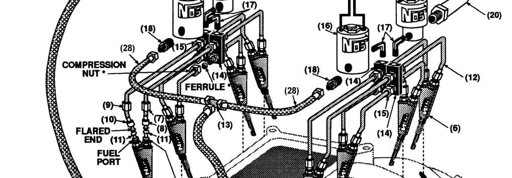
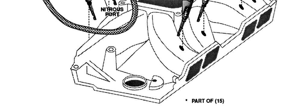
6 1.3 Kit Components Before beginning the installation of your NOS kit, compare the components in your kit with those shown in Figure 1 or 2, and listed in Table 2 or 3. If any components are missing, please contact NOS Technical Support at GOHOLLEY. Table 2 Kit Number 02622NOS Parts List Item Description Quantity NOS P/N (1) Bottle Valve Adapter NOS* (2) Bottle Washer NOS* (3) Bottle Bracket Set NOS* (4) Nitrous Oxide Bottle 10 lb NOS* (5) 1/16 NPT Tap NOS* (6) Fogger Nozzle BNOS (7) 3AN x 3/16 B-Nut (Blue) NOS* (8) 3AN x 3/16 Sleeve (Blue) NOS* (9) 3AN x 3/16 B-Nut (Red) NOS* (10) 3AN x 3/16 Sleeve (Red) NOS* (11) Flare Jets NOS NOS (12) 24 Solenoid Extension Tube SNOS (13) 12 Solenoid Extension Tube SNOS (14) 1/8 NPT Distribution Block (2 In, 16 Out) NOS * (15) 1/8 NPT x 3/16 Compression Fitting NOS (16) Cheater N 2 O Solenoid NOS * (17) 1/8 NPT x 1/8 NPT 90 Fitting NOS (18) N 2 O Filter NOS * (19) Cheater Fuel Solenoid NOS * (20) Fuel Filter NOS (21) 4AN 14 ft. Hose (Blue) NOS * (22) Rubber Fuel Hose (2 ft.) SNOS (23) Hose Clamp 4 36R646A (24) Fuel TEE (5/16 ) NOS (25) Microswitch and Bracket NOS * (26) Arming Switch NOS* (27) Wiring Relay 30 amp** NOS *These parts are also in kit 02620NOS. The other parts of kit 02620NOS will vary. Call NOS Technical Support with any part number questions. ** Wiring and connectors also supplied. 6
7 Figure 1 Kit Number 02622NOS Components 7
8 Table 3 Kit Number 05088NOS Parts List Item Description Quantity NOS P/N (1) Bottle Valve Adapter NOS (2) Bottle Washer NOS (3) Bottle Bracket Set NOS (4) Nitrous Oxide Bottle 10 lb NOS (5) 1/16 NPT Tap NOS (6) Fogger Nozzle BNOS (7) 3AN x 3/16 B-Nut (Blue) NOS (8) 3AN x 3/16 Sleeve (Blue) NOS (9) 3AN x 3/16 B-Nut (Red) NOS (10) 3AN x 3/16 Sleeve (Red) NOS (11) #24, 28, 32, & 36 Flare Jets NOS NOS NOS NOS (12) 3/16 X12 long Tubes SNOS (13) 4AN Blue T block NOS (14) 1/8 NPT Distribution Block NOS (15) 1/8 NPT x 3/16 Compression Fitting NOS (16) Power Shot N 2 O Solenoid NOS (17) 1/8 NPT x 1/8 NPT 90 Fitting NOS (18) N 2 O Filter NOS (19) Power Shot Fuel Solenoid NOS (20) Fuel Filter NOS (21) 4AN 14 ft. N 2 O Hose NOS (22) Rubber Fuel Hose (2 ft.) SNOS (23) Hose Clamp 8 36R646A (24) Fuel TEE (5/16 ) NOS (25) Microswitch and Bracket NOS (26) Arming Switch NOS (27) Wiring Relay 30 amp** NOS (28) 4AN 1ft. Hose NOS ** Wiring and connectors also supplied. 8
9 Figure 2 Kit Number 05088NOS Components 9
10 Chapter 2 Kit Installation Bottle Mounting 2.1 Bottle Mounting Instructions NOTE: Disconnect the battery ground before beginning installation. Before mounting a nitrous bottle in a racing vehicle intended for use in sanctioned events, check with the sanctioning association for any rules regarding this subject. Most associations require the bottle to be mounted within the confines of the safety roll cage with the safety pressure relief cap vented away from the driver s compartment. NOS offers a special safety pressure relief cap (P/N 16166NOS) and an aluminum blow-down tube (P/N 16160NOS) for this purpose. Figure 3 Nitrous Bottle Siphon Tube Orientation Figure 4 Nitrous Bottle Mounting Orientations 2.2 Bottle Orientation Bottle placement is critical to the performance of your NOS nitrous system. It is important to note the orientation of the bottle valve and siphon tube in the nitrous bottle (Figure 3). The bottle must be mounted so that the siphon tube is at the back of the bottle when the liquid N 2 O will be during vehicle acceleration. 10
11 Whenever the bottle is mounted in a lay-down position, the valve handle must be towards the front of the vehicle with the label facing up (Figure 4A). If the bottle is mounted vertically, the valve handle and label must face toward the front of the vehicle (Figure 4B). This orientation will position the siphon tube at the back of the bottle where the liquid N 2 O will be during acceleration. WARNING! DO NOT attempt to remove the siphon tube without completely emptying the bottle of all nitrous and pressure. Failure to completely empty the bottle will result in an explosive condition causing injury or death. A bottle mounted upside-down must have the siphon tube removed before use (Figure 4C). Non-siphon bottles can be specially ordered from NOS. If the bottle must be mounted parallel to the axles of the vehicle (sideways), the valve handle and label must be angled at approximately 45 toward the front of the vehicle (Figure 4D). This orientation will position the siphon tube toward the rear of the bottle. NOTE: When using a bottle with a siphon tube, the tall bracket should be at the valve end of the bottle and the short bracket at the bottom (Figure 4E). The most efficient mounting is the lay-down position (Figure 4A) with the valve handle toward the front of the vehicle. This position allows the greatest amount of liquid to be used before the siphon tube begins to pick up gaseous nitrous oxide. 2.3 Bottle Installation After you have determined the location and orientation of the nitrous bottle, use the following procedure to install the bottle: NOTE: Numbers in parentheses ( ) refer to the parts list (Tables 2 or 3) and the component identification drawing (Figures 1 or 2). Figure 5 or 6 show exploded views of all parts to be installed, while performing the following instructions. 1. Install the bottle nut adapter (1) and washer (2) on the nitrous bottle (4), and tighten securely. 2. Loosely install the bottle mounting brackets (3) on the nitrous bottle, as shown in Figure 4E. 3. Locate the bottle/bracket assembly in the desired mounting location, ensuring that the location will provide easy access to the bottle valve, hose connection, and bracket clamp bolts to facilitate bottle changing. 4. Use the assembled bottle/bracket unit as a pattern to mark and drill four 5/16 holes in the mounting surface. 5. Mount the brackets securely to the surface (recommended minimum of 5/16 bolts or No. 12 sheet metal screws). 6. Secure the nitrous bottle in the mounting brackets and tighten the bracket clamps on the bottle. 11

12 Figure 5 Kit Number 02622NOS Exploded View 12


13 Figure NOS System Exploded View 13
 and the component identification drawing (Figures 2 or 3).")


14 Figure 7 Fogger Nozzle Mounting Position 2x4V Intake Figure 8 Fogger Nozzle Mounting Position Single 4V Intake Installation for 02620NOS Chapter 3 Kit Installation NOTE: Numbers in parentheses ( ) refer to the parts list (Tables 1 or 2) and the component identification drawing (Figures 2 or 3). Figure 5 shows the installation assembly for kit number 02622NOS and Figure 6 shows the installation assembly for kit number 05088NOS. NOTE: NOS provides custom plumbing services for Fogger nozzle installation if you would rather not perform these operations yourself. 3.1 Fogger Nozzle Installation Figure 7 & 8 display typical Fogger nozzle installation locations. Use these figures as a guide for locating your nozzles. NOTE: When mounting Fogger nozzles, ensure that the nozzles and feed lines do not interfere with engine components. 1. Mark the desired Fogger nozzle mounting locations on the intake manifold. 2. Remove the intake manifold from the engine. 3. Drill a 1/4 diameter hole into the intake manifold at each Fogger nozzle mounting location. For aesthetic purposes, all holes on each cylinder bank should be drilled to line up straight. NOTE: Holes should be tapped just deep enough for the discharge orifice of the Fogger nozzle head to protrude through. Be careful not to tap holes too deep, as the Fogger nozzle may not adequately seal. 4. Tap each 1/4 hole with the 1/16 NPT tap (5). 5. Remove all debris from the intake manifold. HINT: Apply Teflon paste to the threads of each Fogger nozzle before installing them in the manifold. This will help prevent vacuum leaks into the intake manifold. 14

15 6. Install a Fogger nozzle (6) into each 1/4 hole, orienting the nozzles so the discharge orifices are pointed down the manifold port toward the intake valve. 7. Install the intake manifold on the engine. 8. Remove the red and blue B-Nuts and sleeves from the Fogger nozzles. 9. Examine Chapter 5, Tuning Suggestions, for the proper nitrous and fuel jet selection for your application. Install the desired flare jets (11) in the Fogger nozzles. 3.2.A Fogger Nozzle Feed Tube Mounting 3.2.A.1 Nitrous Feed Tube Installation NOTE: For professional looking results, the following steps need to be performed with a quality tube-bending tool. NOS sells a tool for this purpose under P/N 15991NOS. 1. Select the mounting location for the distribution block. The block must be positioned so that there is adequate clearance on either end for solenoid mounting. Refer to Figure 5. NOTE: If you are not experienced in tube bending, it is advisable that before you bend each solenoid extension tube, you make a sample tube using either a piece of brake line or a coat hanger. This practice will help you minimize errors and help you to produce an aesthetically pleasing plumbing job. 2. Select two of the 12 solenoid extension tubes (13). Install the blue sleeves (8) and B-Nuts (7) over the flared-ends solenoid extension tubes. 3. Mark the tubes at the desired height above the nozzle for the first bend. The mark should be a minimum of 1 from the end of the tube. Figure 9A Fogger Nozzle Feed Tubes 4. Make the desired bend in the two solenoid extension tubes at the mark. The bend should start at the mark and proceed away from the flared end of the tube. 5. Install the two bent solenoid extension tubes, blue B-Nuts, and sleeves on the closest to the distribution block (make sure the tubes are attached to the nitrous ports on the Fogger nozzles), with the two long legs of the tubes crossing (Figure 9A). Measure between the insides of the tubes and place a center mark across both tubes. 15


16 6. Remove the sixteen compression fittings (15) and the two 90 elbows from the distribution block. Remove the compression nuts and ferrules from the distribution block. Apply Teflon paste to the pipe-style threads of the sixteen compression fittings. Install and tighten the fittings into the distribution block. 7. Measure and mark a centerline on the side of the distribution block. 8. Holding the marked distribution block alongside the installed crossed nitrous feed tubes, so that their center marks are aligned. Place another mark on each solenoid tube extension at the inside end of the two exposed compression fitting body thread sections. 9. Remove the two nitrous feed tubes. Cut off the excess tubes at the inside end marks. Deburr and ream the cut ends. NOTE: Be sure to remove any debris left from cutting and deburring, from the inside of the tube before assembly. 10. Insert the smoothed ends of the solenoid extension tubes into the distribution block fittings with the compression nuts and ferrules. Tighten lightly. 11. Repeat steps 1 through 10 for the Fogger nozzles, using the shortest tube supplied first. 3.2.A.2 Fuel Feed Tube Installation NOTE: For professional looking results, the following steps need to be performed with a quality tube-bending tool. NOS sells a tool for this purpose under P/N 15991NOS. 1. Select the mounting location for the distribution block. The block must be positioned so that there is adequate clearance on either end for solenoid mounting. Refer to Figure 5. NOTE: If you are not experienced in tube bending, it is advisable that before you bend each solenoid extension tube, you make sample tube using either a piece of brake line or a coat hanger. This practice will help you minimize errors and help you to produce an aesthetically pleasing plumbing job. 2. Select two of the 12 solenoid extension tubes (13). Install the red sleeves (10) and B-Nuts (9) over the flared-ends solenoid extension tubes. 3. Mark the tubes at the desired height above the nozzle for the first bend. The mark should be a minimum of 1 from the end of the tube. These tubes are to be used in the fuel ports of the two nozzles closest to the distribution block (1 nozzle on each bank). 4. Make the desired bend in the solenoid extension tubes at the mark. The bend should start at the mark and proceed away from the flared end of the tube. Figure 9B Fogger Nozzle Feed Tubes 16
17 5. Install the two bent solenoid extension tubes, red B-Nuts, and sleeves on Fogger nozzles closest to the distribution block (make sure the tubes are attached to the fuel ports on the Fogger nozzles), with the two long legs of the tubes crossing (Figure 9B). Measure between the insides of the tubes and place a center mark across both tubes. 6. Remove the compression nuts and ferrules from the distribution block. 7. Measure and mark a centerline on the side of the distribution block. 8. Holding the marked distribution block alongside the installed crossed fuel feed tubes, so that their center marks are aligned. Place another mark on each solenoid tube extension at the inside end of the two exposed compression fitting body thread sections. 9. Remove the two fuel feed tubes. Cut off the excess tubes at the inside end marks. Deburr and ream the cut ends. NOTE: Be sure to remove any debris left from cutting and deburring, from the inside of the tube before assembly. 10. Insert the smoothed ends of the solenoid extension tubes into the distribution block fittings with the compression nuts and ferrules. Tighten lightly. 11. Repeat steps 1 through 10 for the Fogger nozzles, using the shortest tube supplied first. 3.2.B Fogger Nozzle Feed Tube Mounting (Kit 05088NOS Only) 3.2.B.1 Nitrous Feed Tube Installation NOTE: For professional looking results, the following steps need to be performed with a quality tube-bending tool. NOS sells a tool for this purpose under P/N 15991NOS. 1. Select the four solenoid extension tubes (12). Measure 1 in from the flared end and mark. Install a blue sleeve (8) and B-Nut (7) on the flared end. NOTE: If you are not experienced in tube bending, it is advisable that before you bend each solenoid extension tube, you make a sample tube using either a piece of brake line or a coat hanger. This practice will help you minimize errors and help you to produce an aesthetically pleasing plumbing job. 2. Make a 90 bend to the solenoid extension tubes at the 1 mark. The bend should start at the 1 mark and proceed away from the flared end of the tube. 3. Install the two bent solenoid extension tubes and blue B-Nut assemblies on the center two Fogger nozzles on one bank of the manifold (make sure the tubes are attached to the nitrous ports on the Fogger nozzles), with the two long legs of the tubes crossing (Figure 10). Measure between the insides of the tubes and place a center mark across both tubes. 4. Remove the four compression fittings (15) and the 90 elbow from one distribution block (14). Remove the compression nuts and ferrules from the compression fittings. Apply Teflon paste to the pipe-style threads of the four compression fittings. Install and tighten the fittings into the distribution block. 5. Measure and mark a centerline on the side of the distribution block. 6. Holding the marked distribution block alongside the installed crossed nitrous feed tubes, so that their center marks are aligned. Place another mark on each solenoid tube extension at the inside end of the two exposed body thread sections. 7. Remove the two nitrous feed tubes. Cut off the excess tubes at the inside end marks. Deburr and ream the cut ends. NOTE: Be sure to remove any debris left from cutting and deburring, from the inside of the tube before assembly. 8. Insert the smoothed ends of the two lower distribution block fittings with the compression nuts and ferrules. Tighten lightly. 9. Insert and lightly tighten a straight nitrous feed tube (12), blue B-Nut (7), and sleeve (8) on the two end Fogger nozzles. 10. Insert and hold in place a straight nitrous feed tube (12) in the two upper ports of the distribution block, so they intersect each of the end nitrous feed tubes at 90. Place a mark on the end nitrous feed tubes at the bottom of the horizontal tubes (Figure 11). 11. Place a mark on the two end feed tubes 5/8 farther down from the mark you made in step Remove the two end nitrous feed tubes. Make a 90 bend in two end feed tubes. The bend should start at the 5/8 mark and proceed away from the flared end. 17
. 15. Remove the two end nitrous feed tubes.")
18 13. Install and loosely tighten the two end nitrous feed tubes. 14. Place a mark on the two end nitrous feed tubes at the inside end of the two exposed fitting body thread sections (same procedure as in step 6). 15. Remove the two end nitrous feed tubes. Cut off the excess tube at the inside end marks. Deburr and ream the cut ends. NOTE: Be sure to remove any debris left from cutting and deburring from the inside of the tube before assembly. 16. Insert the smoothed ends into the two upper distribution block fittings with the compression nuts and ferrules. Tighten lightly. 17. Tighten all nitrous feed tube fittings. 18. Repeat steps 1 through 17 for the other cylinder bank. Figure 10 Fogger Nozzle Feed Tubes Figure 11 End Fogger Nozzle Feed Tubes (Kit Number 05088NOS) 18
19 3.2.B.2 Fuel Feed Tube Installation NOTE: For professional looking results, the following steps need to be performed with a quality tube-bending tool. NOS sells a tool for this purpose under P/N 15991NOS. 1. Select four of the 12 solenoid extension tubes (12), and install a blue B-Nut (7) and a blue sleeve (8) on the flared end. NOTE: If you are not experienced in tube bending, it is advisable that before you bend each solenoid extension tube, you make a sample tube using either a piece of brake line or a coat hanger. This practice will help you minimize errors and help you to produce an aesthetically pleasing plumbing job. 2. Make a 90 bend to the solenoid extension tubes at the 1 mark. The bend should start at the 1 mark and proceed away from the flared end of the tube. 3. Install the two bent solenoid extension tubes and red B-Nut assemblies on the center two Fogger nozzles on one bank of the manifold (make sure the tubes are attached to the nitrous ports on the Fogger nozzles), with the two long legs of the tubes crossing (Figure 9B). Measure between the insides of the tubes and place a center mark across both tubes. 4. Remove the four compression fittings (15) and 90 elbow from one distribution block (14). Remove the compression nuts and ferrules from the compression fittings. Apply Teflon paste to the pipe-style threads on the distribution block fittings. Install and tighten all the fittings into the distribution block. 5. Measure and mark a centerline on the side of the distribution block. 6. Holding the marked distribution block alongside the installed crossed nitrous feed tubes, so that their center marks are aligned. Place another mark on each solenoid tube extension at the inside end of the two exposed fitting body thread sections. 7. Remove the two fuel feed tubes. Cut off the excess tube at the inside end marks. Deburr and ream the cut ends. NOTE: Be sure to remove any debris left from cutting and deburring from the inside of the tube before assembly. 8. Insert the smoothed ends of the two lower distribution block fittings with the compression nuts and ferrules. Tighten lightly. 9. Insert and lightly tighten a straight fuel feed tube (12), sleeve (10), and red B-Nut (9) on the two end Fogger nozzles. 10. Insert and hold in place a straight fuel feed tube (12) in the two upper ports of the distribution block, so they intersect each of the end fuel feed tubes at 90. Place a mark on the end fuel feed tubes at the bottom of the horizontal tubes. See Figure Place a mark on the two end feed tubes 5/8 farther down from the mark you made in step Remove the two end fuel feed tubes. Make a 90 bend in two end feed tubes. The bend should start at the 5/8 mark and proceed away from the flared end. 13. Install and loosely tighten the two end fuel feed tubes. 14. Place a mark on the two end fuel feed tubes at the inside end of the two exposed fitting body thread sections (same procedure as in step 6). 15. Remove the two end fuel feed tubes. Cut off the excess tube at the inside end marks. Deburr and ream the cut ends. NOTE: Be sure to remove any debris left from cutting and deburring from the inside of the tube before assembly. 16. Insert the smoothed ends of the upper distribution block fittings with the compression nuts and ferrules. Tighten lightly. 17. Tighten all the fuel feed tube fittings. 18. Repeat steps 1 through 17 for the other cylinder bank. 3.3 Solenoid Mounting Use the following procedures to install the nitrous solenoid (15) and the fuel solenoid (18). CAUTION: Do not overtighten the vise in the following procedure, or the solenoid will be damaged. NOTE: Apply Teflon-based paste to all pipe-style fittings before assembling solenoids. 19
20 3.3.1 Nitrous Solenoid Installation 1. Clamp the nitrous solenoid in a bench vise. 2. Loosely install the 90 fitting (17) into the outlet port of the nitrous solenoid. 3. Loosely install the nitrous filter fitting (18) into the inlet port of the nitrous solenoid. 4. Trial fit the solenoid, nitrous filter, and 90 fitting in the distribution block. Note the orientation of the fitting and solenoid. Disassemble the 90 fitting and nitrous filter from the solenoid. 5. Reassemble the 90 fitting and nitrous filter using the Teflon paste. Install the solenoid assembly into the distribution block using Teflon paste. Tighten the connections to attain the desired mounting orientation. 6. Repeat steps 1-5 for the other cylinder bank, if working with Kit Number 05088NOS Fuel Solenoid Installation 1. Clamp the fuel solenoid in a bench vise. 2. Loosely install a 90 fitting (17) into the outlet port of the fuel solenoid. 3. Loosely install a fuel filter (20) in the inlet port of the fuel solenoid. 4. Trial fit the solenoid, fuel filter, and 90 fitting in the distribution block (fuel distribution block, if working with Kit Number 05088NOS). Note the orientation of the fitting and solenoid. Disassemble the 90 fitting and fuel filter from the solenoid. 5. Reassemble the 90 fitting and fuel filter using the Teflon paste. Install the solenoid assembly into the distribution block using Teflon paste. Tighten the connections to attain the desired mounting orientation. 6. Repeat steps 1-5 for the other cylinder bank, if working with Kit Number 05088NOS. 3.4 Main Nitrous Feed Line Mounting HINT: Most late-model vehicles have access plugs in the trunk floor that are convenient for line routing. Following the fuel lines along the underbody, and entering the engine bay through the front fender well usually works well. 1. Determine the route for your nitrous feed line to follow. Ensure the path is clear of exhaust system, suspension, steering, wheels, electrical lines and components, and tires. 2. Feed the main nitrous supply line (21) along the proposed route. 3. If it is necessary to support the nitrous supply line under the vehicle, use 1/2 Tinnerman clamps or nylon tie-wraps to support the line securely. 4. Attach the nitrous supply line to the nitrous bottle valve adapter (1). WARNING: Nitrous oxide is dangerous to humans if inhaled or comes in contact with the skin. Always point the nitrous line opening away from people when purging the line. 5. Purge the nitrous supply line. A. Wrap the end of the nitrous line with a rag and hold securely. B. Point the opening away from people. C. Briefly open the bottle valve. 6. If working with Kit Number 05088NOS, connect a 4AN 1 ft. hose (28) to each of the N 2 O filters installed in the inlet ports of the nitrous solenoids. Install the nitrous TEE fitting (13) to the open ends of the two 4AN 1 ft. hoses. 7. Attach the nitrous supply line to the nitrous filter fitting on the inlet port of the nitrous solenoid (Kit Number 02622NOS) or the nitrous TEE fitting (Kit Number 05088NOS). 3.5 Fuel Solenoid Feed Line Installation 1. Connect a 2 ft. rubber hose (22) to the fuel filter(s) installed in the inlet port of the fuel solenoid(s), using the hose clamp(s)(23). 2. Trim the 2 ft. rubber hose(s) to the desired length. 3. If working with Kit Number 05088NOS, install the fuel TEE (24) into the 2 ft. rubber hoses and secure with hose clamps. 20
21 3.6 Main Fuel Line Installation Tips CAUTION: The primary fuel line for your nitrous system should be a separate line dedicated to the nitrous system. Be sure your fuel pump, lines, and regulator are capable of handling the fuel requirements of this system. Inadequate fuel delivery will result in catastrophic engine failure. For suggestions on how to layout a fuel system, refer to the NOS Technical Bulletin #101. (Available from the NOS Technical Department). 3.7 Electrical System Installation Refer to Figures 12, 13, and the procedures in this section for the electrical system installation. WARNING! Death or injury may occur from working on a charged electrical system. 1. Disconnect the car battery at the ground cable (if not already done). WARNING! Binding or dragging of the throttle linkage will create a potentially dangerous stuck-throttle condition. Ensure that the microswitch does not interfere with normal throttle linkage operation. 2. Install the throttle microswitch (25) as follows: HINT: The microswitch may be mounted to the bracket (in a variety of positions) and on either side of the bracket. The bracket may be bent to suit the application. A. Mount the throttle microswitch on the carburetor/intake manifold, so that the throttle linkage movement triggers the microswitch. B. Adjust the microswitch to trigger at wide-open throttle by adjusting the microswitch s position to ensure that the actuation arm of the microswitch clicks at the same point your throttle linkage reaches wide-open throttle against the throttle stop (Position 12A). C. Ensure that the throttle and switch can reach the activation position, as shown in Figure 12B, by using the accelerator pedal. Have an assistant slowly press the pedal to the floor while you listen for the click of the microswitch. 3. Install the NOS arming switch (26) in the vehicle s interior, within easy reach of the driver. 4. Install the wiring relay (27) in the engine compartment near the battery. The relay s orange wire should reach the battery (+) terminal. 5. Connect the orange relay wire (pin 30) to the battery (+) terminal. HINT: Solenoids are not polarized. Either wire will do. 6. Connect one wire from each solenoid together. Join the solenoid wires to the blue relay wire (pin 87). 7. Connect the green relay wire (pin 85) to a ground. 8. Connect the red relay wire (pin 86) to either terminal on the microswitch. 9. Connect the open terminal of the microswitch to the middle (#2) terminal on the arming switch. 10. Connect #1 terminal of the arming switch to a switched +12 volt power source. 11. Connect #3 terminal of the arming switch to a ground (allows internal light to illuminate when armed). 12. Reconnect the battery. 21

22 Figure 12 Throttle Microswitch Installation Figure 13 Wiring Diagram 22
23 CAUTION: Make certain the nitrous bottle is closed and the fuel pump is not running. Failure to comply will result in the intake manifold being filled with nitrous and/or fuel; creating a potential engine explosion on start up. 13. Temporarily ground the open lead of the nitrous solenoid(s). 14. Hold the throttle wide open. 15. Turn the arming switch ON. You should hear a clicking noise if the nitrous solenoid is cycling properly. If no noise is heard, check all the wiring connections against the wiring diagram. 16. Disconnect the temporary solenoid ground. 17. Temporarily ground the open lead of the fuel solenoid. 18. Turn the arming switch ON. You should hear a clicking noise (not as loud as the nitrous) if the fuel solenoid is cycling correctly. If no noise is heard, check all the wiring connections against the wiring diagram. 19. Permanently ground the solenoid wires. 20. Connect the remaining solenoid wire from each solenoid to the ground. Chapter 4 Preparing for Operation After you have completed the installation of your NOS Sportsman Fogger system kit, perform the following checkout procedure before operating your vehicle. NOTE: Before performing steps 1-4, make sure that the nitrous bottle valve is closed and the main nitrous supply line is empty. 1. Turn on the fuel pump. 2. Check all the fuel lines and fittings for leaks. 3. Turn the arming switch on. Set the engine speed at 2000 RPM. Briefly depress the activation arm on the microswitch. Engine speed should decrease (or die altogether), if the fuel delivery system is performing properly; if not, refer to Appendix A, Troubleshooting Guide. 4. Open the nitrous bottle valve. NOTE: There should be no change in the engine idle speed. If the idle speed changes, refer to Appendix A, Troubleshooting Guide. 5. Inspect the nitrous hoses and fittings for leaks. 6. ENJOY! Chapter 5 Tuning Suggestions The Direct Port Injection part of your NOS kit comes standard with 3 levels of nitrous and fuel jets. For maximum performance, the tuning tips listed in Table 3 are suggested. NOTE: Your combination may vary. These guidelines are suggested as a safe starting point in tuning. 5.1 Sportsman Fogger Series Jetting NOS V-8 Sportsman Fogger kits 02622NOS and 05088NOS are designed for direct-port nitrous injection applications. As delivered, NOS kits are jetted to operate with typical carbureted fuel systems (low-pressure pumps and bypassing regulators, operating at approximately 6 psi). In many instances, it is desirable to run elevated fuel pressures to the NOS injection system. To aid the user in selecting jetting combinations, NOS has assembled the following information. 5.1.A Jetting Tips In most applications, maintaining a nitrous/fuel ratio between 5.0:1 (richer) and 6.0:1 (leaner) will provide optimum performance. When changing jetting, we suggest that you start with a rich (5.0:1) nitrous/fuel ratio. Lean the nitrous/fuel jetting until the desired performance is achieved. Be careful not to run an excessively high nitrous/fuel ratio. Severe engine damage can occur. 23
24 5.1.B Recommended Jetting Combinations Jetting combinations for fuel pressures from 6 to 90 psi are listed below. For a particular nitrous-jet/fuel pressure combination, the larger fuel jet listed should produce a 5.0:1 nitrous/fuel ratio. The smaller jet should yield a ratio of about 6.0:1. NOTE: These nitrous/fuel ratios are attained with the nitrous bottle pressure between 900 and 925 psi. Higher pressures will result in leaner nitrous/fuel ratios. Lower pressures will yield a rich mixture. NOTE: Jetting combinations are for engines with single stage nitrous systems only. Always start tuning with nitrous/fuel ratios richer than you expect to run. Gradually lean out the mixture until the desired performance is attained. A slightly rich nitrous/fuel ratio will provide a dramatic increase in engine safety, while only slightly reducing performance. Table 4 Suggested Fogger Series Jetting Map Nitrous Jet Suggested Fuel PSI at PSI N/A N/A N/A N/A N/A N/A N/A N/A N/A N/A N/A N/A Appendix A Troubleshooting Guide The troubleshooting chart on the following pages should help determine and rectify most problems with your installed NOS system. If you still need assistance determining or fixing problems, call NOS Technical Support Department at GOHOLLEY. PROBLEM POSSIBLE CAUSES DIAGNOSTIC PROCEDURE CORRECTIVE ACTION No change in System wired incorrectly. Compare wiring to schematic. Wire per instructions. engine speed when the fuel solenoid is Restricted fuel line. Inspect fuel line for restrictions (crimped Remove restrictions. activated (Chapter or plugged). 6). Malfunctioning fuel solenoid. Disconnect the ground wire for the Repair/replace solenoid. nitrous solenoid. Turn arming switch ON, and depress the microswitch. Fuel Change in engine speed when N 2 0 bottle valve is opened (Chap. 6). Engine runs rich when system is activated. No change in performance when 24 system is activated. Malfunctioning nitrous solenoid. solenoid should make clicking noise. Remove and inspect solenoid. Check for proper inlet and outlet. Check for debris inside solenoid. Repair/replace solenoid. Bottle valve not fully opened. Check bottle valve. Open valve fully. Bottle mounted improperly. Check bottle orientation. Mount bottle properly. Plugged nitrous filter. Inspect filter. Clean/replace filter. Low bottle pressure. Check bottle temperature / pressure. Set bottle temperature to F/ PSI. Inadequate nitrous supply. Weigh bottle. Fill bottle REFILL Mismatched N 2 O/fuel jetting. Compare jetting to recommended values. Install correct jets. Excessive fuel pressure. Install fuel pressure gauge, such as NOS P/N 15931NOS, in the fuel line. Measure the pressure during acceleration, with the system activated. Regulate pressure down, or install smaller fuel jetting. Loose nitrous solenoid wiring. Inspect the solenoid wiring. Repair wiring. Malfunctioning nitrous Rebuild solenoid. solenoid. WARNING: Solenoid discharges nitrous at a high rate. Don t inhale nitrous; death may occur. Skin contact may cause frostbite. Close bottle valve. Disconnect the solenoid outlet port. Disconnect the solenoid (+) lead. Open the nitrous bottle valve. Briefly connect the +12V to the solenoid. Solenoid should discharge N 2 O at a high rate. In-line fuse blown. Check fuse. Replace fuse.
. Connect 12V test light to battery (+) terminal.")
 terminal.")
25 Engine detonates mildly when system is activated. Engine detonates heavily when system is activated. High-rpm misfire when system is activated. Surges under acceleration when system is activated. System wired incorrectly. Compare nitrous wiring to schematic. Wire system per instructions. Loose ground wire(s). Connect 12V test light to battery (+) terminal. Check for continuity at grounds Tighten/repair loose ground(s). noted in schematic. No power to arming switch. With vehicle ignition on, connect 12V test Repair wiring. light to battery (-) terminal. Check for power at pole #1 on arming switch. Malfunctioning arming switch. With vehicle ignition ON, turn arming switch ON. Connect 12V test light to battery (-) terminal. Check for power at red wire on arming switch. Replace arming switch. Malfunctioning throttle microswitch. Temporarily disconnect power relay green wire from microswitch. Connect 12V test light to battery (+) terminal. Manually set microswitch ON. Check for continuity at microswitch positive terminal (Figure 13). Replace throttle microswitch. Overly rich fuel condition. Check for black smoke or backfiring through exhaust with system activated. Install smaller fuel jet or decrease fuel pressure. Excessive ignition timing. Check ignition timing. Reduce timing in 2 increments, up to 8 from non-nitrous conditions. Inadequate octane fuel. Use higher octane fuel; up to 116VPC-16. Spark plug heat range too high. Reduce spark plug heat range (maximum 2 steps). Too much nitrous flow. Reduce nitrous jetting. Inadequate fuel delivery due to: Plugged fuel filter. Inspect fuel filter. Clean or replace filter. Crimped fuel line. Inspect fuel line. Replace crimped line. Weak fuel pump. Install fuel pressure gauge, such as NOS P/N 15931NOS. Run engine under load at WOT, with system activated. Repair/replace fuel pump. Excessive spark plug gap. Inspect spark plugs. Set spark plug gap at to Weak ignition/ignition Inspect components (plug wires, Replace worn components. component failure. distributor cap, etc.) Inadequate supply of nitrous. Check bottle weight. Replace with full bottle. Bottle mounted incorrectly. Compare bottle position and orientation Mount or orient bottle to instructions. correctly. Nitrous Oxide Accessories NOS systems are calibrated for optimum performance with a bottle pressure of psi. The pressure will change with temperature. Heater kits are thermostatically controlled to keep the bottle near 85 F to provide correct pressure. Bottle Heater (P/N 14164NOS) is available for 10 & 15 lb. bottles. Insulating the bottle helps maintain pressure by keeping heat in the bottle when it s cold, or heat out when it s hot outside. The blankets are made of a rugged, easily cleaned Nylon outer shell with insulation. It s also an excellent dress up accessory and perfect for covering battle-scarred bottles. Bottle Blanket (P/N 14165NOS) is a 7 diameter blanket for the 10 lb. bottle. The Remote Bottle Valve (P/N 16058NOS) is the perfect convenience accessory it electronically turns the nitrous bottle on and off with the flick of a switch no more trips to the trunk. It is also great as a safety shut-off valve. It operates on 12V DC. The complete kit includes hardware and installation instructions. P/N 14164NOS P/N 14165NOS P/N 16058NOS 25
. This helps to ensure consistent performances. And, purging looks cool too!")
 is available for 10 lb.")


26 The primary purpose of a Purge Valve (P/N 16030NOS) is to release trapped air or gaseous nitrous from the feed line(s). This helps to ensure consistent performances. And, purging looks cool too! Nitrous Pressure Gauges (P/N 15910NOS) measure from psi (although recommended level is psi) and are essential in monitoring the bottle. The Quick Release Hinged Aluminum Bracket (P/N 14140NOS) is available for 10 lb. and 15 lb. bottles. P/N 14147NOS is available for the carbon fiber bottle. P/N 16030NOS P/N 15910NOS P/N 14140NOS For those who want the ultimate in appearance, NOS offers many popular bottles that are fully polished. P/N PNOS is our 10 lb. fully polished bottle. For optimum weight reduction and distinctive high-tech looks, these DOT-approved NOS carbon fiber-wrapped bottles are it! Weighs about half of the standard bottle (empty). P/N 14747NOS has 12.5 lb. capacity. To order, contact your local dealer. P/N PNOS P/N 14747NOS NOS Technical Service Phone: GOHOLLEY Fax: For online help, please refer to the Tech Service section of our website: A SNOS Date:
Opposed 4 & 6 Cylinder Sportsman Fogger System
 P/N A5064-SNOS Opposed 4 & 6 Cylinder Sportsman Fogger System Kit Numbers: 05080NOS, 05082NOS, & 05085NOS OWNER S MANUAL NOTICE: Installation of Nitrous Oxide Systems Inc. products signifies that you have
Multiple-Carburetor Big Shot Kit Numbers: 02110NOS, NOS, & 02111NOS. Two-Stage Big Shot Kit Numbers: 02401NOS & 02402NOS
 P/N A5054-SNOS Multiple-Carburetor Big Shot Kit Numbers: 02110NOS, 02110-9NOS, & 02111NOS Two-Stage Big Shot Kit Numbers: 02401NOS & 02402NOS OWNER S MANUAL NOTICE: Installation of Nitrous Oxide Systems
Multiple-Carburetor Competition Cheater Kit Number: 02010NOS. Two-Stage Competition Cheater Kit Numbers: 02201NOS and 02202NOS
 Multiple-Carburetor Competition Cheater Kit Number: 02010NOS Two-Stage Competition Cheater Kit Numbers: 02201NOS and 02202NOS OWNER S MANUAL P/N A5052-1-SNOS NOTICE: Installation of Nitrous Oxide Systems
LS-1. Kit Number 05177NOS
 LS-1 Kit Number 05177NOS OWNER S MANUAL P/N A5177-SNOS CONGRATULATIONS on purchasing your NOS Nitrous Oxide Injection System! Your system is composed of the highest quality components available. It should
THROTTLE POSITION CONTROLLED PROGRESSIVE NITROUS CONTROLLER INSTALLATION INSTRUCTIONS OWNER S MANUAL
 P/N A5073-SNOS THROTTLE POSITION CONTROLLED PROGRESSIVE NITROUS CONTROLLER INSTALLATION INSTRUCTIONS Kit Number 15835NOS OWNER S MANUAL NOTICE: Installation of Nitrous Oxide Systems Inc. products signifies
DODGE DAKOTA/DURANGO L OWNER S MANUAL
 P/N 199R-10256 DODGE DAKOTA/DURANGO 98-00 5.2 L Kit Number 05185NOS OWNER S MANUAL CONGRATULATIONS on purchasing your NOS Nitrous Oxide Injection System! Your system is composed of the highest quality
INLINE SPORTSMAN FOGGER SYSTEM
 P/N A5072-SNOS INLINE SPORTSMAN FOGGER SYSTEM Kit Numbers: 05030NOS, 05030-FINOS, 05040NOS, and 05040-FINOS OWNER S MANUAL NOTICE: Installation of Nitrous Oxide Systems Inc. products signifies that you
OWNER S MANUAL P/N 199R-10280
 OWNER S MANUAL P/N 199R-10280 SMALL DISPLACEMENT 2 CYCLE Kit Numbers: 03200-OZNOS NOTICE: Installation of Nitrous Oxide Systems Inc. products signifies that you have read this document and have agreed
Diesel Nitrous Oxide System
 P/N 199R10317 Diesel Nitrous Oxide System Kit Number 02519NOS OWNER S MANUAL CONGRATULATIONS on purchasing your NOS Nitrous Oxide Injection System! Your system is composed of the highest quality components
SNIPER NITROUS SYSTEMS
 SNIPER NITROUS SYSTEMS P/N 07001NOS & 07004NOS GENERAL INFORMATION INSTALLATION INSTRUCTIONS P/N A7001-SNOS The Sniper System is intended for use on domestic V-6 and V-8 engines using a single 4V Holley
P/N A5130-SNOS. 302 Ford SFI. Kit Numbers: 05115NOS OWNER S MANUAL
 P/N A5130-SNOS 302 Ford SFI Kit Numbers: 05115NOS OWNER S MANUAL NOTICE: Installation of Nitrous Oxide Systems Inc. products signifies that you have read this document and have agreed to the terms stated
SNIPER NITROUS SYSTEMS
 SNIPER NITROUS SYSTEMS P/N 07002NOS, 07003NOS, & 07007NOS Part Number 07002NOS Shown GENERAL INFORMATION The Sniper System is intended for use on domestic V-6 and V-8 engines using a single 4V Holley or
PRO FOGGER SYSTEMS OWNER S MANUAL P/N 199R10495
 PRO FOGGER SYSTEMS Kit Numbers: 02462NOS Pro Shot Fogger w/10lb Bottle 02464NOS Pro Shot Fogger Professional Kit Super A Nozzle 02020NOS Upgrade Pro Shot Fogger 2 Single 4150 02021NOS Upgrade Pro Shot
P/N A5055-SNOS POWERSHOT. Kit Numbers: 05001NOS, 05004NOS, 05005NOS, 05008NOS, 05009NOS, & 05011NOS OWNER S MANUAL
 P/N A5055-SNOS POWERSHOT Kit Numbers: 05001NOS, 05004NOS, 05005NOS, 05008NOS, 05009NOS, & 05011NOS OWNER S MANUAL NOTICE: Installation of Nitrous Oxide Systems Inc. products signifies that you have read
LED PURGE VALVE KITS P/N 16028NOS (5 lb. bottle) & 16029NOS (10 lb. bottle) Instruction Sheet P/N 199R10412
 & 16029NOS (10 lb. bottle) Instruction Sheet P/N 199R10412") 1.0 INTRODUCTION: LED PURGE VALVE KITS P/N 16028NOS (5 lb. bottle) & 16029NOS (10 lb. bottle) Instruction Sheet P/N 199R10412 Purge Valve Kits, P/N 16028NOS & 16029NOS are intended for use on competition
1.0 INTRODUCTION: LED PURGE VALVE KITS P/N 16028NOS (5 lb. bottle) & 16029NOS (10 lb. bottle) Instruction Sheet P/N 199R10412 Purge Valve Kits, P/N 16028NOS & 16029NOS are intended for use on competition
P/N A5056-SNOS SUPER POWERSHOT. Kit Numbers: 05101NOS, 05104NOS, & 05105NOS OWNER S MANUAL
 P/N A5056-SNOS SUPER POWERSHOT Kit Numbers: 05101NOS, 05104NOS, & 05105NOS OWNER S MANUAL NOTICE: Installation of Nitrous Oxide Systems Inc. products signifies that you have read this document and have
FACTORY FUEL INJECTION (DRY MANIFOLD SYSTEMS) Kit Numbers: 05120NOS, 05122NOS, & 05175NOS OWNER S MANUAL
 Kit Numbers: 05120NOS, 05122NOS, & 05175NOS OWNER S MANUAL") P/N A5154-SNOS FACTORY FUEL INJECTION (DRY MANIFOLD SYSTEMS) Kit Numbers: 05120NOS, 05122NOS, & 05175NOS OWNER S MANUAL CONGRATULATIONS on purchasing your NOS Nitrous Oxide Injection System. Your system
P/N A5154-SNOS FACTORY FUEL INJECTION (DRY MANIFOLD SYSTEMS) Kit Numbers: 05120NOS, 05122NOS, & 05175NOS OWNER S MANUAL CONGRATULATIONS on purchasing your NOS Nitrous Oxide Injection System. Your system
L Ford SOHC Dry Nitrous Kit
 1999+ 4.6L Ford SOHC Dry Nitrous Kit Kit Number 05116NOS OWNER S MANUAL P/N 199R10261 CONGRATULATIONS on purchasing your NOS Nitrous Oxide Injection System! Your system is assembled with the highest quality
DOUBLE-CROSS TWO-STAGE SYSTEM OWNER S MANUAL
 P/N 199R10336 DOUBLE-CROSS TWO-STAGE SYSTEM Kit Numbers: 02321NOS & 02322NOS OWNER S MANUAL NOTICE: Installation of Nitrous Oxide Systems Inc. products signifies that you have read this document and have
CROSSHAIR PLATE SYSTEM
 CROSSHAIR PLATE SYSTEM NOS Kit Numbers: 02153NOS & 02154NOS NOS Plate Kit Numbers: 12566NOS & 12666NOS 02153NOS shown 12566NOS shown OWNER S MANUAL P/N 199R10494 NOTICE: Installation of Nitrous Oxide Systems
5.0L Ford Holley SysteMax Big Shot Kit
 5.0L Ford Holley SysteMax Big Shot Kit Kit Number: 02119NOS OWNER S MANUAL P/N 199R10329 CONGRATULATIONS on purchasing your NOS Nitrous Oxide Injection System. Your system is composed of the highest quality
2.0L Ford Focus Dry Nitrous Kit
 2.0L Ford Focus Dry Nitrous Kit Kit Number 05186NOS OWNER S MANUAL P/N 199R10285 CONGRATULATIONS on purchasing your NOS Nitrous Oxide Injection System! Your system is assembled with the highest quality
199R IMPORT 4 CYLINDER / MAZDA 2 ROTOR PRO RACE FOGGER SYSTEM Kit Numbers: 04430NOS Soft Plume & 04431NOS Annular Discharge OWNER S MANUAL
 199R-10175-1 IMPORT 4 CYLINDER / MAZDA 2 ROTOR PRO RACE FOGGER SYSTEM Kit Numbers: 04430NOS Soft Plume & 04431NOS Annular Discharge OWNER S MANUAL NOTICE: Installation of Nitrous Oxide Systems Inc. products
GM TBI WET MANIFOLD SYSTEM
 P/N A5153-SNOS GM TBI WET MANIFOLD SYSTEM Kit Numbers: 05153NOS - ALL OWNER S MANUAL CONGRATULATIONS on purchasing your NOS Nitrous Oxide Injection System. Your system is composed of the highest quality
P/N A5130-SNOS. 302 Ford SFI. Kit Numbers: 05115, II, ( Upgrade) OWNER S MANUAL
 OWNER S MANUAL") P/N A5130-SNOS 302 Ford SFI Kit Numbers: 05115, 05115-II, (5115+0015 Upgrade) OWNER S MANUAL NOTICE: Installation of Nitrous Oxide Systems Inc. products signifies that you have read this document and have
P/N A5130-SNOS 302 Ford SFI Kit Numbers: 05115, 05115-II, (5115+0015 Upgrade) OWNER S MANUAL NOTICE: Installation of Nitrous Oxide Systems Inc. products signifies that you have read this document and have
PowerFogger Universal Wet 4 & 6 Cylinder Nitrous Oxide System
 P/N 199R10295 PowerFogger Universal Wet 4 & 6 Cylinder Nitrous Oxide System Kit Number 05130NOS OWNER S MANUAL CONGRATULATIONS on purchasing your NOS Nitrous Oxide Injection System! Your system is composed
OWNER S MANUAL P/N 199R10361
 NOS LS1 Kit Kit Number 05168NOS NOS LS1 Plate Kit Kit Number 13434NOS OWNER S MANUAL P/N 199R10361 CONGRATULATIONS on purchasing your NOS Nitrous Oxide Injection System! Your system is composed of the
DRY EFI PRO FOGGER PROFESSIONAL KITS
 DRY EFI PRO FOGGER PROFESSIONAL KITS Kit Numbers: 04471NOS w/ Super A Nozzle Dual Stage 04472NOS w/ Annular Nozzle Dual Stage (Kits do not contain Bottle, Brackets, or Feed Line) OWNER S MANUAL P/N 199R10592
PowerFogger Dry-To-Wet Conversion Nitrous Oxide System
 PowerFogger Dry-To-Wet Conversion Nitrous Oxide System Kit Number 0031NOS OWNER S MANUAL P/N 199R10326 CONGRATULATIONS on purchasing your NOS Nitrous Oxide Injection System! Your system is composed of
2005 Mustang Wet Single Fogger Kit
 P/N 199R10382-2 2005 Mustang Wet Single Fogger Kit Kit Number 02121NOS OWNER S MANUAL CONGRATULATIONS on purchasing your NOS Nitrous Oxide Injection System! Your system is composed of the highest quality
PowerFogger Universal Wet Drive-By-Wire 8 Cylinder Nitrous Oxide System
 PowerFogger Universal Wet Drive-By-Wire 8 Cylinder Nitrous Oxide System Kit Number 05135NOS OWNER S MANUAL P/N 199R10408-2 CONGRATULATIONS on purchasing your NOS Nitrous Oxide Injection System! Your system
OWNER S MANUAL P/N 199R11242
 NOS 4 Bolt GM LS Kit For 90mm & 105mm, Drive-By-Wire & Cable Operated Throttle Bodies Kit Numbers 05162NOS, 05163NOS, 05164NOS, 05173NOS & 13437NOS OWNER S MANUAL P/N 199R11242 CONGRATULATIONS on purchasing
OWNER S MANUAL for C5-C6 Corvette applications
 OWNER S MANUAL for C5-C6 Corvette applications CONGRATULATIONS on purchasing your DynoTune Nitrous Oxide Injection System! Your system is composed of the highest quality components available. It should
OWNER S MANUAL for Infinity/350Z wet Nitrous System
 OWNER S MANUAL for 03-06 Infinity/350Z wet Nitrous System CONGRATULATIONS on purchasing your DynoTune Nitrous Oxide Injection System! Your system is composed of the highest quality components available.
On all settings above 100 horsepower the following precautions should be observed:
 ELECTRONIC FUEL INJECTED 5.0 COYOTE PLATE SYSTEM INSTALLATION INSTRUCTIONS Congratulations on the purchase of your Nitrous Express Coyote Plate system. Nitrous Express utilizes only the highest quality
OWNER S MANUAL P/N 199R11239
 2011-2016 Mustang 5.0 / Boss 302 Kit Kit Number 02125NOS 2011-2016 Mustang 5.0 / Boss 302 Plate Kit Kit Number 13125NOS OWNER S MANUAL P/N 199R11239 CONGRATULATIONS on purchasing your NOS Nitrous Oxide
V8 EFI Nitrous System
 V8 EFI Nitrous System CONGRATULATIONS on purchasing your DynoTune Nitrous Oxide Injection System! Your system is composed of the highest quality components available. It should provide many miles of trouble-free
OWNER S MANUAL for LS-1 Firebird & Camaro Plate Kit Applications
 OWNER S MANUAL for LS-1 Firebird & Camaro Plate Kit Applications CONGRATULATIONS on purchasing your DynoTune Nitrous Oxide Injection System! Your system is composed of the highest quality components available.
NXd Diesel Stacker System Instructions
 NXd Diesel Stacker System Instructions INSTALLATION INSTRUCTIONS Congratulations on the purchase of your Nitrous Express NXd Diesel Stacker system. You have chosen the finest nitrous system ever. Nitrous
OWNER S MANUAL CONGRATULATIONS
 1 OWNER S MANUAL CONGRATULATIONS ON THE PURCHASE OF YOUR NY-TREX NITROUS OXIDE PERFORMANCE SYSTEM NOTICE: Installation of Ny-Trex performance products signifies that you have read this entire document
TRANSFER PUMP INSTRUCTIONS P/N 14251NOS
 TRANSFER PUMP INSTRUCTIONS P/N 14251NOS A5048-SNOS SAFETY TIPS Never directly inhale nitrous oxide. When inhaled in large quantities, nitrous oxide can cause respiratory ailments or in extreme cases, death
350/370Z System Instructions Part #
 INTRODUCTION Thank you for purchasing the highest quality nitrous system on the market. Nitrous Outlet strives to offer the best product with the best price and customer service available. Nitrous Outlet
TWIN Bottle EFI Motorcycle Applications
 TWIN Bottle EFI Motorcycle Applications CONGRATULATIONS on purchasing your DynoTune Nitrous Oxide Injection System! Your system is composed of the highest quality components available. It should provide
Single Nozzle Systems UNIVERSAL NOZZLE SYSTEM INSTRUCTIONS Part #'S 00-1XXXXX
 INTRODUCTION Thank you for purchasing the highest quality nitrous system on the market. Nitrous Outlet strives to offer the best product with the best price and customer service available. Nitrous Outlet
THROTTLE & RPM-ACTIVATED NITROUS CONTROL SYSTEM P/N 15970NOS
 THROTTLE & RPM-ACTIVATED NITROUS CONTROL SYSTEM P/N 15970NOS Installation Instructions 199R10300 INTRODUCTION: Congratulations on the purchase of your NOS throttle and RPM-activated nitrous control system!
Read all Instructions before beginning!!!!
 Read all Instructions before beginning!!!! Caution EXTREME DANGER Caution Do not use or mix any other manufacturer s products with any Nitrous Express products. Do not use or mix any Nitrous Express products
Read all Instructions before beginning!!!!
 Read all Instructions before beginning!!!! Caution EXTREME DANGER Caution Do not use or mix any other manufacturer s products with any Nitrous Express products. Do not use or mix any Nitrous Express products
YAMAHA RHINO PERFORMER NITROUS SYSTEM
 YAMAHA RHINO PERFORMER NITROUS SYSTEM Table of Contents Page # a. Edelbrock General Warranty : : : : : : : : : : : : : : : : : : : : : : : : : : : : : : : : : : : : : : : : : : : :2 1.0 Introduction to
Part #82064 Add-A-Stage EFI Nitrous System
 1 INSTRUCTIONS Part #82064 Add-A-Stage EFI Nitrous System Thank you for choosing products; we are proud to be your manufacturer of choice. Please read this instruction sheet carefully before beginning
Installation Instructions Diesel Nitrous System (#82028)
") Installation Instructions Diesel Nitrous System (#82028) Thank you for choosing ZEX. If at any time you have questions regarding this or any of our products, please call our Nitrous Help support line at
Installation Instructions Diesel Nitrous System (#82028) Thank you for choosing ZEX. If at any time you have questions regarding this or any of our products, please call our Nitrous Help support line at
Thank You. for purchasing an Edelbrock Nitrous Oxide Injection System. Please take the time to read and understand the following.
 Thank You. for purchasing an Edelbrock Nitrous Oxide Injection System. Nitrous Oxide injection is one of the most exciting performance enhancements for the dollar invested on the market today. With the
Not required for most applications. Not required for most applications. High pressure ( provided) High pressure ( provided)
 High pressure ( provided)") ELECTRIC FUEL PUMPS P/N 12-801-1, 712-801-1, 12-802-1, 12-802-2, 712-802-1, 12-812, 12-815-1, & 712-815-1 FUEL PRESSURE REGULATORS P/N 12-500, 12-501, 12-803, 12-803BP, 12-804, & 15812NOS Installation
ELECTRIC FUEL PUMPS P/N 12-801-1, 712-801-1, 12-802-1, 12-802-2, 712-802-1, 12-812, 12-815-1, & 712-815-1 FUEL PRESSURE REGULATORS P/N 12-500, 12-501, 12-803, 12-803BP, 12-804, & 15812NOS Installation
Read all Instructions before beginning!!!!
 Read all Instructions before beginning!!!! Caution EXTREME DANGER Caution Do not use or mix any other manufacturer s products with any Nitrous Express products. Do not use or mix any Nitrous Express products
ECOTEC 2.2L PERFORMER EFI NITROUS SYSTEM Catalog #70211
 2002-2003 ECOTEC 2.2L PERFORMER EFI NITROUS SYSTEM Catalog #70211 Thank You. for purchasing an Edelbrock Nitrous Oxide Injection System. Nitrous Oxide injection is one of the most exciting performance
DDR SERIES SYSTEM INSTALLATION INSTRUCTIONS
 DDR SERIES SYSTEM INSTALLATION INSTRUCTIONS Read all Instructions before beginning!!!! Caution EXTREME DANGER Caution Do not use or mix any other manufacturer s products with any Nitrous Express products.
Installation Instructions Dual Perimeter Plate Nitrous System (#82185)
") Installation Instructions Dual Perimeter Plate Nitrous System (#82185) Thank you for choosing ZEX. If at any time you have questions regarding this or any of our products, please call our ZEXTEK support
Installation Instructions Dual Perimeter Plate Nitrous System (#82185) Thank you for choosing ZEX. If at any time you have questions regarding this or any of our products, please call our ZEXTEK support
Read all Instructions before beginning!!!!
 Read all Instructions before beginning!!!! Caution EXTREME DANGER Caution Do not use or mix any other manufacturer s products with any Nitrous Express products. Do not use or mix any Nitrous Express products
Installation Instructions
 Installation Instructions for 15912 to 15916 Electric Fuel Pumps & Fuel Pressure Regulators Installation Instructions WARNING! These instructions must be read and fully understood before beginning the
Before starting, disconnect the negative terminal on the battery. If you have any questions about your particular vehicle consult a shop manual.
 CAUTION: An experienced technician familiar with the use and handling of high-pressure cryogenic gases should install this system. If you have any doubt about your skills this system should be taken to
ELECTRONIC FUEL INJECTED SINGLE NOZZLE NITROUS SYSTEMS
 ELECTRONIC FUEL INJECTED SINGLE NOZZLE NITROUS SYSTEMS INSTALLATION INSTRUCTIONS Congratulations on the purchase of your Nitrous Express EFI single nozzle system. Nitrous Express utilizes only the highest
#82312B Blackout Series Race Perimeter Plate Nitrous System
 INSTRUCTIONS 1 #82312B Blackout Series Race Perimeter Plate Nitrous System Thank you for choosing products; we are proud to be your manufacturer of choice. Please read this instruction sheet carefully
EDELBROCK NITROUS SYSTEMS
 EDELBROCK NITROUS SYSTEMS PERFORMER SPORT COMPACT EFI NITROUS SYSTEM For Part Numbers 71000 & 71006 INSTALLATION AND OPERATION INSTRUCTIONS Thank You. for purchasing an Edelbrock Nitrous Oxide Injection
ELECTRIC FUEL PUMPS P/N , , & FUEL PRESSURE REGULATOR P/N
 ELECTRIC FUEL PUMPS P/N 80000100, 80000101, & 80000102 FUEL PRESSURE REGULATOR P/N 80000103 Installation Instructions 199R10583 These instructions must be read and fully understood before beginning the
INSTRUCTIONS. #82028 Diesel Nitrous System. Thank you for choosing ZEX products; we are proud to be your manufacturer of choice.
 1 INSTRUCTIONS #82028 Diesel Nitrous System Thank you for choosing ZEX products; we are proud to be your manufacturer of choice. Why our nitrous system is better: 2 Performance enthusiasts know the potential
Read all Instructions before beginning!!!! Caution EXTREME DANGER Caution
 Read all Instructions before beginning!!!! Caution EXTREME DANGER Caution Do not use or mix any other manufacturer s products with any Nitrous Express products. Do not use or mix any Nitrous Express products
Victor Jr. Plate Upgrade Kits for Square Flange and Dominator Carburetors Kit #70024 and #70025 INSTALLATION INSTRUCTIONS
 Victor Jr. Plate Upgrade Kits for Square Flange and Dominator Carburetors Kit #70024 and #70025 INSTALLATION INSTRUCTIONS Please study these instructions carefully before installing your new Edelbrock
ECOTEC 2.2L PERFORMER EFI NITROUS SYSTEM Catalog #70211
 2002-2003 ECOTEC 2.2L PERFORMER EFI NITROUS SYSTEM Catalog #70211 Table of Contents Page # a. Edelbrock General Warranty...................................................... 2 b. Before You Install Your
Read all Instructions before beginning!!!!
 Read all Instructions before beginning!!!! Caution EXTREME DANGER Caution Do not use or mix any other manufacturer s products with any Nitrous Express products. Do not use or mix any Nitrous Express products
DIRECT PORT (NOZZLE SYSTEM) INSTRUCTIONS MOUNTING THE BOTTLE
 INSTRUCTIONS MOUNTING THE BOTTLE") DIRECT PORT (NOZZLE SYSTEM) INSTRUCTIONS Congratulations on the purchase of your Nitrous Express Direct Port system. Nitrous Express utilizes only the highest quality components designed for the use of
DIRECT PORT (NOZZLE SYSTEM) INSTRUCTIONS Congratulations on the purchase of your Nitrous Express Direct Port system. Nitrous Express utilizes only the highest quality components designed for the use of
Read all Instructions before beginning!!!!
 Read all Instructions before beginning!!!! Caution EXTREME DANGER Caution Do not use or mix any other manufacturer s products with any Nitrous Express products. Do not use or mix any Nitrous Express products
Read all Instructions before beginning!!!!
 Read all Instructions before beginning!!!! Caution EXTREME DANGER Caution Do not use or mix any other manufacturer s products with any Nitrous Express products. Do not use or mix any Nitrous Express products
C40008 & C40009 EXHAUST BRAKES
 EXHAUST BRAKES C40008 & C40009 1995 2003 Ford F250 / F350 7.3 L Powerstroke Diesel with manual transmissions 1995 1998 Ford F250 / F350 7.3 L Powerstroke Diesel with automatic transmission* *Requires the
NXD12001, 12002, DIESEL STACKER NITROUS INSTALLATION INSTRUCTIONS
 NXD12001, 12002, 12003 DIESEL STACKER NITROUS INSTALLATION INSTRUCTIONS Congratulations on the purchase of your Nitrous Express Diesel Nitrous System. This system does not add fuel and is intended to be
MOUNTING THE BOTTLE MOUNTING THE NITROUS PLATE
 READ UNDERSTAND AND FOLLOW these instructions. If there is something you don t understand, STOP! Call the NX tech department for help. 9:00 AM to 5:00 PM CST 940-767-7694. The installation procedures are
5.0 COYOTE HIGH OUTPUT PLATE SYSTEM INSTALLATION INSTRUCTIONS. On all settings above 100 horsepower the following precautions should be observed:
 5.0 COYOTE HIGH OUTPUT PLATE SYSTEM INSTALLATION INSTRUCTIONS Congratulations on the purchase of your Nitrous Express Coyote High Output Plate system. Nitrous Express utilizes only the highest quality
WEBER CARBURETOR TROUBLESHOOTING GUIDE
 This guide is to help pinpoint problems by diagnosing engine symptoms associated with specific vehicle operating conditions. The chart will guide you step by step to help correct these problems. For successful
INSTRUCTIONS. #82044 Race Diesel Nitrous System
 INSTRUCTIONS #82044 Race Diesel Nitrous System Thank you for choosing ZEX products; we are proud to be your manufacturer of choice. Kit Parts List Description Qty. Description Qty. Nitrous Solenoid 2.088
#82037 Race EFI Nitrous System
 1 INSTRUCTIONS #82037 Race EFI Nitrous System Thank you for choosing products; we are proud to be your manufacturer of choice. Please read this instruction sheet carefully before beginning installation,
Read all Instructions before beginning!!!!
 Read all Instructions before beginning!!!! Caution EXTREME DANGER Caution Do not use or mix any other manufacturer s products with any Nitrous Express products. Do not use or mix any Nitrous Express products
Before starting, disconnect the negative terminal on the battery. If you have any questions about your particular vehicle consult a shop manual.
 DRY NITROUS SYSTEM INSTALLATION INSTRUCTIONS CAUTION: An experienced technician familiar with the use and handling of high-pressure cryogenic gases should install this system. If you have any doubt about
ELECTRONIC FUEL INJECTED FORD GEMINI TWIN PLATE SYSTEMS
 ELECTRONIC FUEL INJECTED FORD GEMINI TWIN PLATE SYSTEMS INSTALLATION INSTRUCTIONS Congratulations on the purchase of your Nitrous Express Ford Plate system. You have chosen the finest nitrous system ever.
#82087 Gen III High Output Nitrous System
 INSTRUCTIONS #82087 Gen III High Output Nitrous System Thank you for choosing products; we are proud to be your manufacturer of choice. Please read this instruction sheet carefully before beginning installation,
EDELBROCK NITROUS SYSTEM FOR MUSTANG V6 CATALOG #70415
 EDELBROCK NITROUS SYSTEM FOR 2005-2007 MUSTANG V6 CATALOG #70415 Table of Contents a. Edelbrock General Warranty......................................................... 2 b. Before You Install Your Edelbrock
3-BOLT LS NITROUS PLATE SYSTEM INSTALLATION INSTRUCTIONS. On all settings above 100 horsepower the following precautions should be observed:
 3-BOLT LS NITROUS PLATE SYSTEM INSTALLATION INSTRUCTIONS Congratulations on the purchase of your Nitrous Express LS Plate system. Nitrous Express utilizes only the highest quality components designed for
Read all Instructions before beginning!!!! Caution EXTREME DANGER Caution
 Read all Instructions before beginning!!!! Caution EXTREME DANGER Caution Do not use or mix any other manufacturer s products with any Nitrous Express products. Do not use or mix any Nitrous Express products
ELECTRONIC FUEL INJECTED FR-S/BRZ PLATE SYSTEM INSTALLATION INSTRUCTIONS
 ELECTRONIC FUEL INJECTED FR-S/BRZ PLATE SYSTEM INSTALLATION INSTRUCTIONS Congratulations on the purchase of your Nitrous Express Plate system. Nitrous Express utilizes only the highest quality components
Installation Instructions EFI V8 BB Direct Port Nitrous System (82063)
") Installation Instructions EFI V8 BB Direct Port Nitrous System (82063) Thank you for choosing ZEX. If at any time you have questions regarding this or any of our products, please call our ZEXTEK support
Installation Instructions EFI V8 BB Direct Port Nitrous System (82063) Thank you for choosing ZEX. If at any time you have questions regarding this or any of our products, please call our ZEXTEK support
2244 West McDowell Road Phoenix, AZ RACE (fax)
") 2244 West McDowell Road Phoenix, AZ 85009 602-257-9591 1-800-274-RACE 602-340-8429 (fax) www.hughesperformance.com HUGHES PERFORMANCE HP2215 VALVE BODY Installation Instructions 9/24/16 For over 45 years
2244 West McDowell Road Phoenix, AZ 85009 602-257-9591 1-800-274-RACE 602-340-8429 (fax) www.hughesperformance.com HUGHES PERFORMANCE HP2215 VALVE BODY Installation Instructions 9/24/16 For over 45 years
40001MP MAstEr JEt pack (10 of EVErY size JEt) Nitrous ExprEss FuEl / Nitrous JEt (.099)
 Nitrous ExprEss FuEl / Nitrous JEt (.099)") 137 138 139 140 141 Part no. DescriPtion 40001MP MAstEr JEt pack (10 of EVErY size JEt) 17009 Nitrous ExprEss FuEl / Nitrous JEt (.009) 17010 Nitrous ExprEss FuEl / Nitrous JEt (.010) 17012 Nitrous ExprEss
137 138 139 140 141 Part no. DescriPtion 40001MP MAstEr JEt pack (10 of EVErY size JEt) 17009 Nitrous ExprEss FuEl / Nitrous JEt (.009) 17010 Nitrous ExprEss FuEl / Nitrous JEt (.010) 17012 Nitrous ExprEss
UNIVERSAL SINGLE E1 NOZZLE WET NITROUS SYSTEM. Catalog #71820
 UNIVERSAL SINGLE E1 NOZZLE WET NITROUS SYSTEM Table of Contents Page # a. Edelbrock General Warranty......................................................... 2 b. Before You Install Your Edelbrock Nitrous
#82221 EFI Perimeter Plate Nitrous System
 1 INSTRUCTIONS #82221 EFI Perimeter Plate Nitrous System Thank you for choosing products; we are proud to be your manufacturer of choice. Please read this instruction sheet carefully before beginning installation,
QUICK FUEL TECHNOLOGY HOT ROD SERIES CARBURETORS SLAYER SERIES CARBURETORS SUPER STREET SERIES CARBURETORS
 QUICK FUEL TECHNOLOGY Installation Instructions HOT ROD SERIES CARBURETORS SLAYER SERIES CARBURETORS SUPER STREET SERIES CARBURETORS HR-580-VS 580 CFM Vac. Secondary!!! SS-680-VS 680 CFM Vac. Secondary
#82044 Race Diesel Nitrous System
 INSTRUCTIONS #82044 Race Diesel Nitrous System Thank you for choosing products; we are proud to be your manufacturer of choice. Please read this instruction sheet carefully before beginning installation,
ELECTRONIC FUEL INJECTED NITROUS SYSTEMS
 ELECTRONIC FUEL INJECTED NITROUS SYSTEMS INSTALLATION INSTRUCTIONS Congratulations on the purchase of your Nitrous Express EFI system. You have chosen the finest nitrous system ever. Nitrous Express utilizes
ELECTRONIC FUEL INJECTED 5.0 COYOTE PLATE SYSTEM INSTALLATION INSTRUCTIONS
 ELECTRONIC FUEL INJECTED 5.0 COYOTE PLATE SYSTEM INSTALLATION INSTRUCTIONS Congratulations on the purchase of your Nitrous Express Coyote Plate system. Nitrous Express utilizes only the highest quality
Read all Instructions before beginning!!!!
 Read all Instructions before beginning!!!! Caution EXTREME DANGER Caution Do not use or mix any other manufacturer s products with any Nitrous Express products. Do not use or mix any Nitrous Express products
DOMINATOR FUEL PUMPS P/N & Installation Instructions 199R10573
 DOMINATOR FUEL PUMPS P/N 12-1400 & 12-1800 Installation Instructions 199R10573 WARNING! THESE INSTRUCTIONS MUST BE READ AND FULLY UNDERSTOOD BEFORE BEGINNING INSTALLATION. FAILURE TO FOLLOW THESE INSTRUCTIONS
Instruction Packet Trick Flow Specialties TFX Nitrous Systems by Nitrous Express For Trick Flow EFI manifolds
 Instruction Packet Trick Flow Specialties TFX Nitrous Systems by Nitrous Express For Trick Flow EFI manifolds Thank you for purchasing a Trick Flow TFX Nitrous System. These systems are the most advanced,
SCHNITZ. Racing DRY , Dry NOS System
 Table of Contents SCHNITZ DRY-3008-2, Dry System 1.0 General Safety Precautions Page 1 2.0 Important Notice Page 2 3.0 Warranty Page 2 4.0 Items Included in Kit Page 2 5.0 Power Commander Tuning Tips Page
TECH INFORMATION EMPI D Performance 2-Barrel Carburetor
 TECH INFORMATION EMPI D Performance 2-Barrel Carburetor The New EMPI D 2-Barrel Performance Carburetor.Built specifically for the VW Aftermarket. With all the features that you have asked for More Progression