MACHINE SENSORS CONTROL PANEL CONVEYOR SYSTEM SYSTEM SENSORS...
|
|
|
- Brian Atkins
- 5 years ago
- Views:
Transcription
1 TABLE OF CONTENTS TABLE OF CONTENTS... 1 CONTROL PANEL MACHINE SENSORS... 5 CONVEYOR SYSTEM... 6 SYSTEM SENSORS... 6 INFEED BACKUP... 6 OUTFEED BACKUP... 6 CHANGEOVERS... 6 CONVEYOR GUIDES ADJUSTMENTS... 6 DETECTION SYSTEM-SENSOR ADJUSTMENT... 7 DETECTION SYSTEM-SENSOR ORIENTATION... 7 DIVERTER GUIDES ADJUSTMENTS... 7 CONVEYOR GUIDES ADJUSTMENTS... 8 MAINTENANCE... 9 TROUBLESHOOTING... 9 STARWHEEL SYSTEM SENSORS BOTTLE DETECTION LID ON BOTTLE REJECT ACKNOWLEDGE REJECT TRAY FULL STARWHEEL CLUTCH.. 10 CAP ON BOTTLE CAP HIGH REED SWITCH OUTFEED ACTUATOR REED SWITCH OUTFEED GATE REED SWITCH REJECT ACTUATOR CHANGEOVERS ANTI SPIN GRIPPER REMOVAL STARWHEEL PLATE STARWHEEL REMOVAL STARWHEEL GUIDE REMOVAL REJECT GUIDE REMOVAL INFEED GUIDE REMOVAL STARWHEEL ALIGNMENT Rebel PPC-111 Section 7 Page 1 / 33 - Rev.0
2 MAINTENANCE.. 13 MAINTENANCE.. 14 TROUBLESHOOTING LID APPLICATION SYSTEM SYSTEM SENSORS LID LOADED-VACUUM DETECTION CHANGEOVERS MAINTENANCE.. 18 TROUBLESHOOTING CAP FEEDER SYSTEM SYSTEM SENSORS TRAY LOADER SAFETY DOOR LOW CAP IN TRACK CAP CLEAR RELEASE POSITION TRAY IN POSITION CAP PICKUP DOWN POSITION CAP PICKUP UP POSITION TRAY EJECTOR REJECT/LOAD POSITION (REEDSWITCH) CHANGEOVERS SUCTION CUP SPACING ADJUSTMENT OVERHEAD SYSTEM CHANGEOVER TRAY EJECTOR POSITION CAP CONVEYOR SAFETY GUARD REMOVAL CAP CONVEYOR WIDTH ADJUSTMENT MAINTENANCE.. 22 TROUBLESHOOTING CAP FEEDING STARWHEEL CHANGEOVERS CAP FEEDING STARWHEEL HEIGHT ADJUSTMENT CAP FEEDING STARWHEEL REMOVAL MAINTENANCE.. 25 TROUBLESHOOTING TURRET SYSTEM SENSORS CAP IN PRETIGHT CHUCK PICK UP TURRET CHANGEOVERS TURRET HEIGHT ADJUSTMENT Rebel PPC-111 Section 7 Page 2 / 33 - Rev.0
3 CHUCK REMOVAL MAINTENANCE TROUBLESHOOTING FINAL TORQUE CHANGEOVERS HEIGHT ADJUSTMENT PRESSURE ADJUSTMENT CHUCK REPLACEMENT TORQUE LIMITER REMOVAL TROUBLESHOOTING EUROGUARD SYSTEM SENSORS SAFETY DOOR Rebel PPC-111 Section 7 Page 3 / 33 - Rev.0


4 CONTROL PANEL The control panel controls every system available on the equipment. From the control panel the user can adjust the various settings of each individual system as well as receive information and feedback on the machine status such as alarms, bottle count, and so forth. Some systems come equipped with a vision system, and the vision system output can be seen in a separate screen on the back of the control panel. (For more information about the vision system, see the manufacturer documentation). Rebel PPC-111 Section 7 Page 4 / 33 - Rev.0
5 MACHINE SENSORS # PART NUMBER DESCRIPTION # PART NUMBER DESCRIPTION 1 EPH191 Infeed Backup 14 EPH800 Cap High 2 EPH217 Bottle Detection 15 EPH801 Cap on Bottle 3 PAC377 Lid Loaded-Vacuum Detection 16 EPH802 Cap Low 4 EPH217 Lid on Bottle 17 EPH172 Safety Door EPH217 Cap in Pretight Chuck 18 EPH172 Tray Loader Safety Door EPH217 Reject Acknowledge 19 EPH532 Low Cap in Track 7 EPH217R Reject Tray Full 20 EPH532 Cap Clear Release Position 8 EPH191 Outfeed Backup 21 EPH217 Tray in Position 9 EPH651 Starwheel Clutch 22 PAC856 Cap Pickup Up Position 10 PAC880 Reed Switch Outfeed Actuator 23 PAC856 Cap Pickup Down Position 11 PAC1127 Reed Switch Outfeed Gate 24 CYL1046 Tray Ejector Reject Position (Reed Switch) 12 PAC1132 Reed Switch Reject Actuator 25 CYL1046 Tray Ejector Load Position (Reed Switch) 13 EPH651 Pick Up Turret Rebel PPC-111 Section 7 Page 5 / 33 - Rev.0


6 CONVEYOR SYSTEM The conveyor system s task is to move the bottles through the equipment and link up the various machines in a production line. SYSTEM SENSORS INFEED BACKUP This sensor detects bottles at the infeed of the equipment. If no bottles are detected for a set amount of time, the machine will go in standby. OUTFEED BACKUP This sensor detects bottles at the outfeed of the equipment. If no bottles are detected for a set amount of time, the machine will go in standby. CHANGEOVERS CONVEYOR GUIDES ADJUSTMENTS The conveyor guides can be adjusted both vertically and horizontally. In either case loosen the fastener and slide the guide to the desired position and retighten the adjustment to complete the change. There is no precise numerical adjustment for the guide spacing, the bottle should be able to travel freely on the conveyor but be constrained enough that it does not fall off the conveyor usually a ~3mm clearance is best. Rebel PPC-111 Section 7 Page 6 / 33 - Rev.0


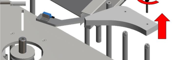
7 DETECTION SYSTEM-SENSOR ADJUSTMENT The sensor can be adjusted both vertically and horizontally. In either case loosen the fastener and slide the guide to the desired position and retighten the adjustment to complete the change. DETECTION SYSTEM-SENSOR ORIENTATION Adjust the angle of the sensor so that the beam deflects perpendicularly off of the reflector. DIVERTER GUIDES ADJUSTMENTS To accommodate a different format the diverter guides may need to be widened or narrowed. Loosen the fasteners holding the diverter guides in place and slide them to the desired position in order to accommodate the new format. The gap needs to be wide enough for the bottle to pass unhindered but narrow enough so that the bottle does not fall. A ~3mm clearance is best. Rebel PPC-111 Section 7 Page 7 / 33 - Rev.0


8 CONVEYOR GUIDES ADJUSTMENTS The infeed sensor should detect the top of the bottle and verify that the guide rails do not interfere with the detection of the bottle. This will detect a lack of or fallen bottles at the infeed of the machine and will switch the machine mode to Stand-By until bottles are detected anew. The outfeed sensor should detect the bottom of the bottle and verify that the guide rails do not interfere with the detection of the bottle. This will detect bottle accumulation and will switch the machine mode to Stand-By until the accumulation dissipates. Rebel PPC-111 Section 7 Page 8 / 33 - Rev.0
 (there are 2 fuses on the drive).")

9 MAINTENANCE 1 1 # DESCRIPTION LUBRICANTS INTERVAL 1 Lubrication of the conveyor chains and sprockets. Synco-Superlube 960Hrs TROUBLESHOOTING The conveyor does not work. Cause Solution The conveyor is not connected. Verify the connection. The fuse on the DC drive is burned out. Change the fuse (s) (there are 2 fuses on the drive). The switch on the control panel is not on. The speed dial is at 0. An emergency was activated. Belt is broken. Bearings seized. Turn the switch on. Increase the speed dial. Correct the problem, release the emergency and reset the machine. Remove and replace belt with new one. Remove and replace bearings. Rebel PPC-111 Section 7 Page 9 / 33 - Rev.0


10 STARWHEEL The center starwheel indexes the bottles in order for them to be processed by each of the stations. The starwheel has two anti-spin grippers at both the cap application turret and the final torque station. They are actuated by pneumatic cylinders and hold the bottle in place while the cap is applied. At the outfeed there are two possible scenarios: 1: A bottle is tagged as good 2: A bottle is tagged as a reject Good bottles, once they reach the outfeed are simply bumped by the outfeed actuator onto the outfeed conveyor. Tagged rejects on the other hand need to travel to the reject station. To ensure that the tagged rejects do not travel onto the outfeed conveyor a gate is actuated that blocks the path to the outfeed conveyor. After the strawheel indexes once more the gate is retracted and the reject actuator bumps the tagged reject into the reject station. SYSTEM SENSORS BOTTLE DETECTION This fiber-optic sensor detects bottles entering the infeed starwheel. The fiber-optic acts as a tracking sensor for the systems on the machine. If no bottles are detected the machine will not activate the systems when the empty starwheel pocket arrive at these same stations preventing any product loss. LID ON BOTTLE This sensor will detect if a lid is located on the bottle. If no lid is detected the station preceding the faulty detection will not be activated. The bottle will then be rejected. REJECT ACKNOWLEDGE This will indicate that a rejected vial traveled to the reject tray. REJECT TRAY FULL This sensor will detect if the reject tray is full. When the tray is full the machine will stop. STARWHEEL CLUTCH This photocell detects an excessive amount of torque on the system created by an object preventing the starwheel from indexing. A LED on the control panel will light up indicating a problem, correct the problem and reset the machine by pressing on RESET button and then the START button to restart the machine. CAP ON BOTTLE This fiber-optic sensor detects the presence of caps on bottles. If no caps are detected the bottle will then be rejected. Rebel PPC-111 Section 7 Page 10 / 33 - Rev.0


11 CAP HIGH This fiber-optic sensor detects the presence of caps on bottles that are too low. If too low caps are detected the bottle will then be rejected. REED SWITCH OUTFEED ACTUATOR This sensor monitors that position of the outfeed actuator that directs bottles onto the outfeed track. REED SWITCH OUTFEED GATE This sensor monitors the presence of the outfeed gate, which prevents tagged rejects from entering the outfeed track. REED SWITCH REJECT ACTUATOR This sensor monitors that position of the reject actuator that directs bottles onto the reject track. CHANGEOVERS ANTI SPIN GRIPPER REMOVAL Unscrew the thumbscrews and carefully remove the grippers. STARWHEEL PLATE Unscrew the starknobs indicated and lift the starwheel hub and plate carefully to remove them. STARWHEEL REMOVAL With the starwheel plate and hub removed lift the starwheel to remove it. Rebel PPC-111 Section 7 Page 11 / 33 - Rev.0


12 STARWHEEL GUIDE REMOVAL Remove the indicated starknobs and carefully lift the guide to remove it. REJECT GUIDE REMOVAL Unscrew the indicated starknobs and carefully lift the guides to remove them. INFEED GUIDE REMOVAL Unscrew the indicated starknobs and carefully lift the guide to remove it. Rebel PPC-111 Section 7 Page 12 / 33 - Rev.0


13 STARWHEEL ALIGNMENT To correctly be aligned the key starwheel positions are 2 and 4, which are below the cap turret pickup pocket and the final torque. 1 2 Once 2 is correctly aligned below the turret chuck, position 1 should be aligned with the cap infeed. Once 4 is correctly placed position 5 will be correctly aligned with the bottle infeed. Position 3 at the end of the adjustments should line up below the turret chuck that will place the cap on the bottle SENSOR HEIGHT ADJUSTMENT To adjust the height of the sensors, loosen the ratchet handle locking the adjustment in place and use the adjustment dial to modify the height of the sensor. MAINTENANCE 1 1 # DESCRIPTION LUBRICANTS INTERVALS 1 Lubricate up and down shaft and height adjustment screw Synco - SuperLube 960 Hrs Rebel PPC-111 Section 7 Page 13 / 33 - Rev.0


 Verify fuses (if installed) Relay is defective (if installed) Drive is defective.")

14 MAINTENANCE # DESCRIPTION LUBRICANTS INTERVALS 1 Lubrication of the indexing plate. Lubrication of the indexing cam. Synco - SuperLube 960 Hrs 2 Verify the condition of the anti-spin inserts N.A. Daily 3 Clean the starwheel of debris N.A. Daily TROUBLESHOOTING Starwheel does not start. Cause Solution No power to starwheel. Verify main power connection. Emergency has been triggered. Alarm has been generated (See alarm for description). Reset button is illuminated. Speed is set to zero. The system is not enabled on the control panel. Starting conditions have not been met. Start button was not pressed. Stop button was pressed. Breaker is triggered (if installed) Verify fuses (if installed) Relay is defective (if installed) Drive is defective. Release emergency pushbutton and reset the starwheel. Clear alarm and reset the starwheel. Press the reset button. Verify / change the value. Enable the system on the control panel. Verify starting conditions. Press the start button. Press the start button. Verify and / or reset the breaker. Verify and / or replace fuse(s). Verify and / or replace the relay module. Verify and / or replace the drive. Rebel PPC-111 Section 7 Page 14 / 33 - Rev.0

15 LID APPLICATION SYSTEM S Lids are stacked on the system between the four rods. As the chuck comes up, it opens up the rods, and picks up a lid that drops. Once that it picks it up the chuck flips over and places the lid on the bottle. SYSTEM SENSORS LID LOADED-VACUUM DETECTION This vacuum switch verifies that a lid has been picked up by the lid application chuck. Rebel PPC-111 Section 7 Page 15 / 33 - Rev.0


 Loosen the thumb screw located on the front side of the lid application system.")
16 CHANGEOVERS LID APPLICATION SYSTEM HEIGHT ADJUSTMENT To adjust the height of the lid application system, set the machine in JOG mode. Start slowly jogging the machine and pay careful attention to the lid application system, it may crash into the machine if it is not adequetly adjusted. Jog the machine to the lowest cam position of the lid application system with the bottle in place, but if the system gets to low modify the height adjustments indicated below as needed. Once that the cam has reached its lowest positions, the final adjustments can be made. (Note: The final position of the lid applicatin system should be such that the chuck drops the lid when it is roughly 1mm above the bottle. ) Loosen the thumb screw located on the front side of the lid application system. Then adjust the height of the lid application station by referring to the set up sheets and the new bottle format needed. To raise and lower the lid application chuck travel path loosen the thumbscrew and move the spline shaft as needed. Rebel PPC-111 Section 7 Page 16 / 33 - Rev.0


17 LID HOPPER CHANGE To change the lid hopper unscrew the thumbscrew holding it in place and carefully remove the lid hopper. LID APPLICATION CHUCK CHANGE To change the lid application chuck, unscrew its supporting thumbscrews and carefully remove the chuck. Rebel PPC-111 Section 7 Page 17 / 33 - Rev.0


18 MAINTENANCE # DESCRIPTION LUBRICANTS INTERVALS 1 Lubrication of the shaft. Synco - SuperLube 960 Hrs 2 Lubrication of the height adjustment screw. Synco - SuperLube 960 Hrs 3 Verify that the suction cup is free and clean of any debris and dirt. N.A. Daily TROUBLESHOOTING Lids application system does not function correctly Cause Rod guide are bent. The lids are not being grabbed by the chuck Solution Straighten out the rod guides, for better lid flow The lids are too staggered they should be a straight column as much as possible There is not enough vacuum generated by the chuck verify the suction cup for blockages and debris Rebel PPC-111 Section 7 Page 18 / 33 - Rev.0
19 CAP FEEDER SYSTEM The cap feeder system is supplied with lids in trays. The trays travel along the conveyor and stops at the end. The caps are picked by an overhead suction cup system that grabs individual rows of caps and places them on the machine feeding conveyor. Once that all of the rows in the tray are taken, the tray is bumped off into the reject bin and a subsequent tray is brought to the same place to allow the overhead suction cup system to grab more caps. SYSTEM SENSORS TRAY LOADER SAFETY DOOR 1-4 These sensors will detect the position of the Tray Loader safety doors. When a door is opened the equipment will trigger an alarm displayed on the equipment s control panel. Once the door is closed the equipment will have to be restarted by pressing on the control panels reset button. If the alarm was properly dealt with the reset button light will turn itself off, if the door stays opened the reset button light will stay illuminated. Once the problem corrected the operator will be able to restart the equipment by pressing the start button. LOW CAP IN TRACK This is the fiber optic sensor on the end of the cap conveyor. If this sensor fails to detect caps in this portion of the chute the machine will stop the infeed of bottles, this will prevent containers passing through the machine when there are no caps in the cap supply chute. CAP CLEAR RELEASE POSITION This sensor is used by the overhead cap suction cups to indicate the position at which it is safe to drop the lids onto the cap conveyor. TRAY IN POSITION This sensor is used by the overhead cap suction cups to indicate that a tray of caps is in position. Rebel PPC-111 Section 7 Page 19 / 33 - Rev.0


20 CAP PICKUP DOWN POSITION This sensor will detect when the cap pickup system has reached its lowest position. CAP PICKUP UP POSITION This sensor will detect when the cap pickup system has reached its highest position. TRAY EJECTOR REJECT/LOAD POSITION (REEDSWITCH) This sensor is used by the tray feeding conveyor to only bring forth new trays when the tray ejector has returned to its load position after having ejected an empty tray. CHANGEOVERS SUCTION CUP SPACING ADJUSTMENT To adjust the spacing of the suction cups loosen the ratchet handle and slide the suction cup to the desired position. OVERHEAD SYSTEM CHANGEOVER To change the overhead for a different format remove the screws and carefully pull down the overhead. Rebel PPC-111 Section 7 Page 20 / 33 - Rev.0


21 TRAY EJECTOR POSITION To adjust the position of the tray ejector, loosen the ratchet and slide the ejector to the desired position. CAP CONVEYOR SAFETY GUARD REMOVAL To remove the cap conveyor safety guard unscrew all of the indicated thumbscrews and carefully lift the guard to remove it. CAP CONVEYOR WIDTH ADJUSTMENT To adjust the width of the conveyor loosen the thumbscrews locking the guide rails in place and slide the guide rails to the desired position. Rebel PPC-111 Section 7 Page 21 / 33 - Rev.0


22 MAINTENANCE # DESCRIPTION LUBRICANTS INTERVALS 1 Lubrication of the shaft. Synco - SuperLube 960 Hrs 2 Verify that the suction cups are clear of and dirt and debris. N.A. Daily 3 Verify that the conveyor is clear of and dirt and debris. N.A. Daily TROUBLESHOOTING Caps are not being picked up Cause Suction is not sufficient Solution Verify that there is no debris or dirt clogging the suction cups. Rebel PPC-111 Section 7 Page 22 / 33 - Rev.0


23 CAP FEEDING STARWHEEL The cap feeding starwheel takes caps from the cap feeding conveyor and prepares them for the turret to grab them and place them on bottles. CHANGEOVERS CAP FEEDING STARWHEEL HEIGHT ADJUSTMENT To adjust the height of the starwheel loosen the ratchet handle and raise or lower the starwheel to the desired height. Rebel PPC-111 Section 7 Page 23 / 33 - Rev.0


24 CAP FEEDING STARWHEEL REMOVAL To remove the capping starwheel remove the center starknob and carefully lift the starwheel hub and starwheel to remove it. CAP FEEDING STARWHEEL GUIDE REMOVAL To remove the cap feeding starwheel guides remove the indicated thumbscrews and lift up the guides to remove them. Rebel PPC-111 Section 7 Page 24 / 33 - Rev.0


25 MAINTENANCE 1 # DESCRIPTION LUBRICANTS INTERVALS 1 Clean the starwheel of debris N.A. Daily Rebel PPC-111 Section 7 Page 25 / 33 - Rev.0
26 TROUBLESHOOTING Starwheel does not start. No power to starwheel. Cause Solution Verify main power connection. Emergency has been triggered. Alarm has been generated (See alarm for description). Reset button is illuminated. Speed is set to zero. The system is not enabled on the control panel. Starting conditions have not been met. Start button was not pressed. Stop button was pressed. Release emergency pushbutton and reset the starwheel. Clear alarm and reset the starwheel. Press the reset button. Verify / change the value. Enable the system on the control panel. Verify starting conditions. Press the start button. Press the start button. Breaker is triggered (if installed) Verify fuses (if installed) Relay is defective (if installed) Drive is defective. Verify and / or reset the breaker. Verify and / or replace fuse(s). Verify and / or replace the relay module. Verify and / or replace the drive. Rebel PPC-111 Section 7 Page 26 / 33 - Rev.0


27 TURRET The turret is a system that is in continuous motion and is powered by air motors driven by a gear system. As the turret moves in a circular motion driven by the large gear beneath the machine, it picks up caps from the cap feeding starwheel and places them on bottles in the main starwheel. The chucks pick up the caps and as they place them on the bottle they spin such as to pre-tighten the cap on the bottle. SYSTEM SENSORS CAP IN PRETIGHT CHUCK This sensor will detect if the chuck is holding a cap. PICK UP TURRET This sensor calculates and keeps track of the turret height displacement. Rebel PPC-111 Section 7 Page 27 / 33 - Rev.0


28 CHANGEOVERS TURRET HEIGHT ADJUSTMENT To adjust the height of the turret, loosen the ratchet handle locking the adjustment in place and turn the handwheel to the desired height. CHUCK REMOVAL To remove the chucks carefully use a wrench to remove the fasteners keeping it in place. Rebel PPC-111 Section 7 Page 28 / 33 - Rev.0


29 MAINTENANCE # DESCRIPTION LUBRICANTS INTERVAL 1 Lubrication of the height adjustment screw Synco-Superlube 960 Hrs. 2 Lubrication of the up and down shaft Synco-Superlube 960 Hrs. 2 Verify the condition of the chucks and replace as necessary N/A Daily TROUBLESHOOTING The turret does not work. Cause Solution The air motors are not working Caps are not being picked up Check air is sufficient Verify air motor oil, after long standing time Verify that there is no debris or dirt clogging the suction cups. Rebel PPC-111 Section 7 Page 29 / 33 - Rev.0


30 FINAL TORQUE This system finalizes the cap application with the right amount of torque onto the bottles. CHANGEOVERS HEIGHT ADJUSTMENT Move the final torque system up or down until the desired height is reached. The numbers on the counter should correspond with the setup sheet. Rebel PPC-111 Section 7 Page 30 / 33 - Rev.0


31 PRESSURE ADJUSTMENT To adjust the pressure of the system, simply turn the knob clockwise to add pressure to the system to counter clockwise to remove. CHUCK REPLACEMENT Unscrew the chuck and remove it. TORQUE LIMITER REMOVAL Put a wrench on the shaft of the motor and a second one at the bottom of the chuck and turn them the opposite way until it gets loose enough for you to pull it out. Rebel PPC-111 Section 7 Page 31 / 33 - Rev.0


32 MAINTENANCE NCE # DESCRIPTION 1 Lubrication of the up / down shafts and height adjustment screw. LUBRICANTS Synco-Superlube INTERVAL 2 Verify the condition of the timing belts N.A. Daily 3 960Hrs 3 Lubrication of the cam and cam follower Synco-Superlube 960Hrs 4 Verify the condition of the chuck N.A. Daily TROUBLESHOOTING Caps are not completely tightened. Cause Height of the head is too high. The speed of the chuck is not fast enough. Caps break during operation. Cause Height of the torqueing system is too low. Bottles break during operation. Cause Height of the torqueing system is too low. Solution Adjust the height of the torqueing system. Adjust the speed of the torqueing chuck. Solution Adjust the height of the torqueing system. Solution Adjust the height of the torqueing system. Rebel PPC-111 Section 7 Page 32 / 33 - Rev.0


33 EUROGUARD The Euroguard is there to protect the machine s operator from any injuries. If a door on the Euroguard is opened while the machine is operating it will automatically stop the machine or if the machine is not in function it will not start because of the interlock switches mounted on the doors. This will prevent any injuries to the personnel and damages to the machine and its components. SYSTEM SENSORS SAFETY DOOR 1-6 These sensors will detect the position of the Euroguard doors. When a door is opened the equipment will trigger an alarm displayed on the equipments control panel. Once the door is closed the equipment will have to be restarted by pressing on the control panels reset button. If the alarm was properly dealt with the reset button light will turn itself off, if the door stays opened the reset button light will stay illuminated. Once the problem corrected the operator will be able to restart the equipment by pressing the start button. Rebel PPC-111 Section 7 Page 33 / 33 - Rev.0

34
JBI Docupunch P33 Automatic Punch
 JBI Docupunch P33 Automatic Punch Instruction Manual Provided By http://www.mybinding.com http://www.mybindingblog.com TABLE OF CONTENTS SECTION I: INSTALLATION & TESTING: 1) Uncrating, Inspection & removal
FD 342 Document Folder
 FD 342 Document Folder 6/2010 OPERATOR MANUAL FIRST EDITION TABLE OF CONTENTS SUBJECT PAGE DESCRIPTION 1 SPECIFICATIONS 1 UNPACKING 2 SETUP 2 CONTROL PANEL 3 OPERATION 4 SETTING CUSTOM FOLDS 5 BATCH COUNTING
INSTALLATION AND OPERATING INSTRUCTIONS
 ASTRO ENVELOPE FEEDER AMC-2000 INSTALLATION AND OPERATING INSTRUCTIONS INTRODUCTION Thank you for purchasing the Astro Envelope Feeder. It is fast, efficient, reliable, and designed to provide many years
Cyclone 600 Upcut Cut Off Saw
 Cyclone 600 Upcut Cut Off Saw WARNING The operator must thoroughly read and understand this manual before operating the cut off saw or starting any servicing. All safety and warning instructions should
RolsplicerTM. Maintenance Manual And Illustrated Parts List
 RolsplicerTM Maintenance Manual And Illustrated Parts List List of Illustrations Figure Page. Rolsplicer 3 2. Roller Adjustment 4 3. Rolsplicer 6 4. Lid Hold Down Assembly 8 5. Automatic Lid Speed Adjustment
INSTALLATION AND OPERATING INSTRUCTIONS
 ASTRO ENVELOPE FEEDER AMC-2000 INSTALLATION AND OPERATING INSTRUCTIONS INTRODUCTION Thank you for purchasing the Astro Envelope Feeder. It is fast, efficient, reliable, and is designed to give you many
2020 Dual Tabber Operation Manual
 2020 Dual Tabber Operation Manual Revision 1.2 10 Clipper Road 10/24/2006 West Conshohocken, PA 19428-2721 Tel : 800-523-0320 / 610-825-6205 Fax: 610-825-1397 www.secap.com Index SECTION 1 Introduction
INSTALLATION AND OPERATING INSTRUCTIONS
 ASTRO ENVELOPE FEEDER AMC-2000-5 FOR RYOBI 3302 / ITEK 3985 (2 COLOR) INSTALLATION AND OPERATING INSTRUCTIONS INTRODUCTION Thank you for purchasing the Astro Envelope Feeder. It is fast, efficient, reliable,
Manufacturing Lab Project
 Manufacturing Lab Project Automated Yoyo Assembly Manual ENGR 480 Spring 2014 Brendan Kennedy Justin Mouser Mark Meelhuysen Jayden Heck Contents Introduction... 3 Loading Machine... 4 Starting Machine...
Tooling Assistance Center
 Safeguards are designed into this application equipment to protect operators and maintenance personnel from most hazards during equipment operation. However, certain safety precautions must be taken by
SECTION B1: MACHINE COMPONENTS
 SECTION B1: MACHINE COMPONENTS The machine portion of the Injected Metal Assembly system provides the means for: holding, heating and injecting the alloy; distributing and controlling electrical, pneumatic,
IMPORTANT! DO NOT THROW AWAY THE SHIPPING CARTON AND PACKING MATERIAL
 Operator s Manual IMPORTANT! DO NOT THROW AWAY THE SHIPPING CARTON AND PACKING MATERIAL ii Table of Contents Operator Safety... 1 Introduction... 2 Unpacking and Setup... 3 Unpacking... 3 Setup... 4 ROCKET
Arch HTH Water Chemicals Commercial Equipment Trouble Shooting Guide
 Arch HTH Water Chemicals Commercial Equipment Trouble Shooting Guide 8/28/00 TROUBLESHOOTER S GUIDE PROBLEM CAUSE SOLUTION Insufficient water flow to chlorinator Check water flow through Flow Controller
PREPOINT CHAMFER GRINDER MODEL Section 1. Set up and operation
 PREPOINT CHAMFER GRINDER MODEL 6-94 Set up and operation Section 1 1. Installation of the proper size collet. This machine used a 5-C style collet. This can be changed by loosening of he set screw located
Opera ons & Parts Manual VersaClipper 3100
 Opera ons & Parts Manual VersaClipper 3100 Heavy Duty Servo Driven & Computer Controlled Fully Automa c and Highly Versa le Clip A aching Machine Model #3100 Serial # 1 Revised 09/21/17 Table of Contents
DESIGNED BY EXPERIENCE PLASTIC SPHERE DISPENSER USER MANUAL. Manufactured by PSDS, Inc. for sole distribution by:
 DESIGNED BY EXPERIENCE PLASTIC SPHERE DISPENSER USER MANUAL Manufactured by PSDS, Inc. for sole distribution by: AEROSTAT, INC. 8830 AIRPORT BLVD LEESBURG, FL 34788 WEBSITE: AEROSTATINC.COM TEL: 352 787-1348
Sure-Feed Engineering Inc. SE-900-EI. Operation & Parts Manual
 . SE-900-EI Operation & Parts Manual SE 900 EI OWNERS MANUAL Table of Contents 1. Installation guide 2. Set-up instructions 3. Operation instructions 4. Cleaning 5. Troubleshooting 6. Parts manual 7. Electrical
Adjustable Angled Incline Conveyor Owners Manual with Operating Instructions
 Adjustable Angled Incline Conveyor Owners Manual with Operating Instructions Revision 012211 Table of Contents Basic Conveyor Features 3 Getting Started 4 Setting Up the Incline Conveyor 5 Belt Removal
Terminal Assembly Machine
 1996 Instruction/Service Manual Terminal Assembly Machine Acme Manufacturing Inc. #J9876 Built by: For: The Wiley Company ACME Manufacturing, Inc. 2000 Coyote Lane Roadrunner, MN 55122 (612) 555-1234 (612)
MiTek Machinery Division. Service Bulletin
 MiTek Machinery Division Service Bulletin Machinery Affected: Document: Title: Applies To: Distribution: RoofGlider Press SB198 Redesigned Push Bar Push Bars Manufactured With Gas Spring and Clamp-Style
Contents. Overview Pinsetter Orientation...1-4
 Contents Overview...1-3 Pinsetter Orientation...1-4 Pinsetter Description...1-5 Ball Pit...1-5 Ball Cushion...1-5 Transport Band...1-7 Ball Accelerator...1-8 Pin Elevator...1-10 Distributor...1-14 Setting
SE-1200-MP ECO - SERIES
 Inc. SE-1200-MP ECO - SERIES Operation & Parts Manual SE 1200 MP ECO -SERIES OWNERS MANUAL Table of Contents 1. Installation guide 2. Set-up instructions 3. Operation instructions 4. Cleaning 5. Troubleshooting
TABLE OF CONTENTS. Warranty Disclaimers Delivery Checklist After Sale Checklist Safety Set Up... 8
 TABLE OF CONTENTS Pickett Equipment Warranty... 2 Warranty Disclaimers... 3 Delivery Checklist... 4 After Sale Checklist... 4 Safety... 5-7 Set Up... 8 Machine Adjustments and Operation... 9 Maintenance
General Information. Notations and Conventions. Compatibility Check. Kit Description. Call-Outs. Part Lists Great Plains Manufacturing, Inc.
 Part Lists Great Plains Manufacturing, Inc. 1 Installation Instructions Loup Shaft Monitor Used with Drill models: Compatible with most 1995 and later, two- and three-box drills with 5 8 -inch square main
FPS- 80. Manual. Reverso Pumps, Inc. Ph: (954)
") FPS- 80 Manual Table of Contents System Overview... 1 Control Panel Overview... 2 Technical Specifications... 3 Electrical and Installation... Tank Diagrams... 5 Initial Setup... 6 Digital Timer Instructions:
FPS- 80 Manual Table of Contents System Overview... 1 Control Panel Overview... 2 Technical Specifications... 3 Electrical and Installation... Tank Diagrams... 5 Initial Setup... 6 Digital Timer Instructions:
Linear Commutated Meat Filler IMC-CMF100 INTERNATIONAL MACHINE CONCEPTS WELCOMES YOU TO YOUR NEW MACHINE
 Linear Commutated Meat Filler IMC-CMF100 INTERNATIONAL MACHINE CONCEPTS WELCOMES YOU TO YOUR NEW MACHINE Operation Manual: Date 2017. Version 1. Serial Number 1 CONTENTS Chapter 1 Machine Description 1.1
OPERATING INSTRUCTIONS IC-2, 3,4,5,6 INTELLICUT SERVO CUTTER Version 5.1xx Created 11/2009
 OPERATING INSTRUCTIONS IC-2, 3,4,5,6 INTELLICUT SERVO CUTTER Version 5.1xx Created 11/2009 "CAUTION" "DO NOT OPERATE MACHINE WITH GUARD REMOVED" UNCRATE AND INSPECT This machine has been carefully crated
Perfmaster Air V3. Serial Number. Date
 Perfmaster Air V3 12-2015 Serial Number Date TABLE OF CONTENTS SPECIFICATIONS.3 SAFETY PROCEDURES/CARE & MAINTENANCE..4 COMPONENT IDENTIFICATION 5 DELIVERY TRAY ASSEMBLY.6 PAPER STOP ASSEMBLIES..7 MACHINE
FACF AUTOMATIC CAPSULE FILLER SERIES USER MANUAL
 FACF AUTOMATIC CAPSULE FILLER SERIES USER MANUAL LFA Tablet Presses is a trading name of LFA Machines Oxford LTD All of the content in this document is covered by copyright CONTENTS Page 1. Introduction
: Automation Laboratory 1
 Table A.1 shows elements found in FluidSIM library with a brief description for each of them. Compressed air supply The compressed air supply provides the needed compressed air. It contains a pressure
CLEAN ROOM DEVICES, LLC "WHERE TUBING AND FITTINGS COME TOGETHER"
 CLEAN ROOM DEVICES, LLC "WHERE TUBING AND FITTINGS COME TOGETHER" CRD600AF Automatic Fitting Inserter With Auto Feed OPERATIONS MANUAL (Shown with optional alcohol dispenser) 1 VERSION 1.1 LAST EDITED
SECTION G2: CABLE PROCESSOR MODULE MAINTENANCE
 SECTION G2: CABLE PROCESSOR MODULE MAINTENANCE Cable Processor Module overview WARNING! When tipping the Cable Processor Module back, (after removing the toggle arm pin), use extreme caution not to drop
INSTRUCTION MANUAL FOR ESP GROSS BAGGING SCALE MODEL GB-17, GB-25, GB-32, GBAO-21, GBAO-25, GBAO-31 & GBAO-37
 INSTRUCTION MANUAL FOR ESP GROSS BAGGING SCALE MODEL GB-17, GB-25, GB-32, GBAO-21, GBAO-25, GBAO-31 & GBAO-37 The Don Marshall Company, Inc. PO Box 124, 235 Maple St., Plain City, OH 43064 614-873-8520,
Property of American Airlines
 Date Maintenance Check list The inspection and preventive maintenance schedule of the Power Stow Rollertrack is as follows: Daily (10 hrs), Weekly (50 hrs.), every 6 months ( hrs.), yearly (1 hrs.) and
Z TECHNICAL INSTRUCTIONS
 ÍNDICE: Z40 2.0 TECHNICAL INSTRUCTIONS 1.- Error list 2.- Replace the control board 3.- Opening the machine 4.- Replace the power board 5.- Dismantling motor and gear box 6.- Assembly of gear box 7.- Pushing
Contents. Section 5: Adjustments Ball Detect Adjustment Transport Band Tension Adjustment
 Contents Section 5: Adjustments... 5-3 1. Ball Detect Adjustment... 5-3 2. Transport Band Tension Adjustment... 5-5 3. Transport Band Drive Belt Tension Adjustment... 5-7 4. Ball Cushion Adjustment...
INSTALLATION INSTRUCTIONS AMBASSADOR DRUM OVERHEAD SERIES 100 DUMBWAITER
 INSTALLATION INSTRUCTIONS AMBASSADOR DRUM OVERHEAD SERIES 100 DUMBWAITER The installation of Matot Drum Dumbwaiters should only be performed by qualified, experienced, and trained elevator installers.
MODULATING SERVICE ELECTRIC ACTUATORS OPERATION AND MAINTENANCE MANUAL COMMERCIAL AND INDUSTRIAL VALVES AND AUTOMATION
 SERIES 000/S-X MODULATING SERVICE ELECTRIC ACTUATORS OPERATION AND MAINTENANCE MANUAL COMMERCIAL AND INDUSTRIAL VALVES AND AUTOMATION Publication S000X- VER045- For information on this product and other
2. Fault Code Procedures
 2. Fault Procedures Section Contents Page Introduction.......................2-3 Section 2 Entry Flow Chart...........2-4 Paper Jam Entry Flow Chart..........2-5 Status Fault s Table 1. Status Entry Table
CABINET REEL OPERATING INSTRUCTIONS
 CABINET REEL OPERATING INSTRUCTIONS MODELS 15, 25, 40 & 60 SERIES RAPID-AIR CORPORATION 4601 KISHWAUKEE ST. ROCKFORD, IL 61109-2925 Phone: (815) 397-2578 Fax: (815) 398-3887 Web Site: www.rapidair.com
TECHNICAL SERVICE BULLETIN: TSB
 TECHNICAL SERVICE BULLETIN: TSB2015-007 To: From: Global Service Organization, ichem VELOCITY and iricell Distributors Iris Diagnostics Service and Support Date: 10 June 2015 Subject: STRIP PROVIDER MODULE
VOLUMETRIC BLENDING SYSTEM OPERATION MANUAL
 VOLUMETRIC BLENDING SYSTEM OPERATION MANUAL 12285 E. MAIN ST. MARSHALL, IL 62441 PHONE: 217-826-6352 FAX: 217-826-8551 WEB SITE: www.yargus.com 1 OPENING SCREEN The OPENING SCREEN is the screen that the
INSTALLATION INSTRUCTIONS AND OPERATION MANUAL
 INSTALLATION INSTRUCTIONS AND OPERATION MANUAL Commercial and Industrial Fire Door Operator Logic Control Restricted Duty Fire Door Operators IMPORTANT INSTALLATION INSTRUCTIONS WARNING To reduce the risk
icreaseexcel Digital Creaser Operators Manual
 2-2013 6-2013 Version 1.0 3.0 icreaseexcel Digital Creaser Operators Manual WWW.MBMCORP.COM 800-223-2508 TABLE OF CONTENTS SPECIFICATIONS.1a SAFETY PROCEDURES/CARE & MAINTENANCE..1b COMPONENT IDENTIFICATION
OPERATING INSTRUCTIONS FOR. Gold-Place TM. Manual Pick & Place with Dispenser System Model MPP-21
 OPERATING INSTRUCTIONS FOR Gold-Place TM Manual Pick & Place with Dispenser System Model MPP-21 AUTOMATED PRODUCTION SYSTEMS, INC. 2840 Pine Road Huntingdon Valley PA 19006 Phone: (215) 938-1000 FAX: (215)
Loose Components. VetPro 5000 Wall / Cabinet Mount Installation. Applies to Models:
 VetPro 5000 Wall / Cabinet Mount Installation warning Equipment not suitable for use in the presence of a flammable anesthetic mixture. Applies to Models: 8001-001 8001-002 8001-005 8001-006 Loose Components
Auto Sentry-eXP Maintenance. Revised 12/21/07
 Auto Sentry-eXP Maintenance Revised 12/21/07 Maintenance Procedures for Auto Sentry exp Bill Dispenser Credit Card Reader Bill Acceptor Bill Dispenser Maintenance Bill Dispenser Problem / Cause Bill Dispenser
Embedded Rack Slide-out System
 Embedded Rack Slide-out System SERVICE MANUAL Rev: 02.16.2017 Page 1 Electric Embedded Rack Slide-out System TABLE OF CONTENTS Safety Information 3 Product Information 3 Operation 4 Extending Slide-Out
Multi Processing Station with Oven 24V
 - 536632 Multi Processing Station with Oven 24V I9 Q10 Q4 I1 O14 I8 Q7/Q8 I1 I3 I4 I2 Q3 not in the picture: Q1, Q2, Q5, Q6, Q9, Q11, Q12, Q13, I4, I5, I6, I7 Circuit layout of the Multi Processing Station
Part Number: Thiele Technologies, Inc. - Streamfeeder. All rights reserved.
 V-710DM Manual Part Number: 00900394 2013 Thiele Technologies, Inc. - Streamfeeder. All rights reserved. No part of this publication may be reproduced, photocopied, stored on a retrieval system, or transmitted
TRITON ERROR CODES ERROR CODE MODEL SERIES DESCRIPTION RESOLUTION
 0 8100, 9100, 9600, 9610, 9615, 9640, No errors 9650, 9700, 9710, 9705, 9750, RL5000 (SDD),RL5000 (TDM), RT2000, 9800, MAKO, SuperScrip 1 9615 Unsolicited note channel 1 2 9615 Unsolicited note channel
Feeding Concepts, Inc Vibratory Feeding Equipment Troubleshooting Manual
 Feeding Concepts, Inc Vibratory Feeding Equipment Troubleshooting Manual Provided by: Feeding Concepts, Inc. 15235 Herriman Blvd. Noblesville, IN 46060 P- 317.773.2040 F- 317.773.1494 www.feedingconcepts.com
OPERATOR MANUAL Magnetic Conveyor
 OPERATOR MANUAL Magnetic Conveyor Document No. 94-03, Rev. 0816-3 WARNINGS THIS CONVEYOR IS DESIGNED FOR A SPECIFIC APPLICATION. CHECK FRAME AND CHAIN FOR DAMAGE DURING SHIPMENT. READ THE MANUAL FOR PROPER
CF-10 Option Operating Instructions
 CF-10 Option Operating Instructions for High-Low Track Sensors with Vibratory Bowl Single Feed Selection Version 1.2 May 27, 2009 Prepared by GPD Global Documentation Department Copyright (C) 2009 GPD
OPEN/CLOSE SERVICE ELECTRIC ACTUATORS OPERATION AND MAINTENANCE MANUAL COMMERCIAL AND INDUSTRIAL VALVES AND AUTOMATION
 SERIES 1000-X OPEN/CLOSE SERVICE ELECTRIC ACTUATORS OPERATION AND MAINTENANCE MANUAL COMMERCIAL AND INDUSTRIAL VALVES AND AUTOMATION Publication S1000X-110 VER0215-1 For information on this product and
CRD610 Automatic Fitting Inserter
 CRD610 Automatic Fitting Inserter OPERATIONS MANUAL VERSION 1.2 LAST EDITED 12.12.2018 cleanroomdevices.com 1 Table of Contents Title Page. 1 Table of Contents...2 1.0 General Product & Safety Information....3
AUTOMATIC FOODSERVICE EQUIPMENT. AUTOMATIC ELECTRIC BROILER MODELS 824E & 850E and 624E & 650E. B-Series Broiler OWNER S MANUAL
 AUTOMATIC FOODSERVICE EQUIPMENT AUTOMATIC ELECTRIC BROILER MODELS 824E & 850E and 624E & 650E B-Series Broiler OWNER S MANUAL FOR YOUR SAFETY: Do not store or use gasoline or other flammable vapors or
Vacuum Transport. Manual
 Vacuum Transport Manual 2018 Streamfeeder - BW Integrated Systems. All rights reserved. No part of this publication may be reproduced, photocopied, stored on a retrieval system, or transmitted without
GBP784B INSTALLATION TOOL
 GBP784B INSTALLATION TOOL GAGE BILT MADE IN U.S.A. GAGE BILT PRODUCTS CORP. 14500 Barber Drive (586) 771-7664 Warren, Mi 48088 (586) 771-2665 Fax e-mail:solutions@gagebilt.com / www.gagebilt.com TABLE
Tagger with Stand. Manual
 Tagger with Stand Manual 2018 Streamfeeder - BW Integrated Systems. All rights reserved. No part of this publication may be reproduced, photocopied, stored on a retrieval system, or transmitted without
Pressure chlorine changeover unit C 7520
 BW 2 24 04 / 1 Content 1. Scope of delivery 2. Device description 3. Installation 4. Operation 5. Shutdown 6. Maintenance 7. Troubleshooting 1 Scope of delivery The chlorine gas changeover unit C 7520
CLEAN ROOM DEVICES, LLC "WHERE TUBING AND FITTINGS COME TOGETHER"
 CLEAN ROOM DEVICES, LLC "WHERE TUBING AND FITTINGS COME TOGETHER" CRD600 Automatic Fitting Inserter OPERATIONS MANUAL VERSION 2.1 LAST EDITED 7.25.14 DOCUMENT NUMBER 001 cleanroomdevices.com 1 Table of
Overhead Set. Measure WARNING. General Information
 Page 1 of 16 003-004 Overhead Set Measure General Information All overhead lash measurements must be made when the engine is cold. Stabilized coolant temperature must be at 60 C [140 F] or below. Remove
COOKSON OWNER S MANUAL
 COOKSON OWNER S MANUAL ELECTRIC CLUTCH RELEASE FOR TUBULAR MOTOR 3117(1) ECN 0951 BY RG 10/28/10 1 PATENT NO. 6,155,324 SPECIFICATIONS ELECTRICAL SPECIFICATIONS TUBULAR MOTOR FOR TUBULAR MOTOR ELECTRICAL
AUTOMATIC SPINDLE CAPPER
 OPERATIONS MANUAL AUTOMATIC SPINDLE CAPPER (Shown above in one of several configurations.) 3999 East Hupp Road, Bldg. R-43 Phone: 219-393-3600 La Porte, IN 46350 Fax: 219-393-5260 www.liquidpackagingsolution.com
COOKSON OWNER'S MANUAL
 COOKSON OWNER'S MANUAL FDO-A10 INDUSTRIAL DUTY FIRE DOOR OPERATOR R L I S T E D 3040233 US CONTROL PANEL SERIAL# OPERATOR SERIAL# 9001.DWG ECN 0959 REV 4 SPECIFICATIONS MOTOR TYPE:...INTERMITTENT HORSEPOWER:...1/8
Automatic filling and closing machine Minican Universal
 Automatic filling and closing machine Minican Universal for liquids for pasty products for powder for granules Equipment: Optionals: Indexing table with 12 or 16 stations Application of droppers 1-4 Filling
200 Shadylane Drive Philipsburg, PA Phone: (814) Fax: (814) Service Manual. Model 642E Centrifuge
 Fax: (814) Service Manual. Model 642E Centrifuge") 200 Shadylane Drive Philipsburg, PA 16866 Phone: (814) 342-6205 Fax: (814) 342-4510 www.druckerdiagnostics.com Service Manual Model 642E Centrifuge MODEL 642E SERVICE MANUAL REV: Original Issue 1 CONTENTS
200 Shadylane Drive Philipsburg, PA 16866 Phone: (814) 342-6205 Fax: (814) 342-4510 www.druckerdiagnostics.com Service Manual Model 642E Centrifuge MODEL 642E SERVICE MANUAL REV: Original Issue 1 CONTENTS
OLYMPIAN MODEL 740 Operation and Service Manual
 OLYMPIAN MODEL 740 Operation and Service Manual P/N 133911-102 FCI MANUAL P/N 133865-001 Data herein has been verified and validated and believed adequate for the intended use. If the machine or procedures
TERMINATOR User Manual
 TERMINATOR User Manual TERMINATOR User Manual Table of Contents Section Page 1 2 3 4 5 6 7 8 9 10 11 12 13 14 15 16 17 18 19 20 21 Introduction Safety Precautions Features and Benefits Overview of the
STI MODEL10. Capsule Filling Machine OPERATION AND MAINTENANCE MANUAL. Ver. 5
 STI MODEL10 Ver. 5 Capsule Filling Machine OPERATION AND MAINTENANCE MANUAL STI MODEL 10 Ver. 5 SPECIFICATIONS Dimensions: 30 deep 55 wide 73-1/4 high (with casters) Weight: Approximately 1,000 pounds
SECTION B: SYSTEM OPERATING COMPONENTS
 SECTION B: SYSTEM OPERATING COMPONENTS A brief description of the machine, Cable Processor Module and tooling will provide a better understanding of the various functions of the IMA system. SECTION B1:
OEM TM-50 Quick Start Guide
 This quick start guide provides basic setup and operating instructions for the OEM TM-50. The intended use of the OEM TM-50 Taping Machine is to produce taped reels of individually sealed and consistently
AutoStream - Model HV. Manual
 AutoStream - Model HV Manual Part Number: 901546 This Product Guide supports autoloader part number 311-0314 with serial numbers beginning with B1011Axxx 2014 Thiele Technologies, Inc. - Streamfeeder.
Reliant Inserter Feeder (115v) Manual
 Manual") Reliant Inserter Feeder (115v) Manual 2018 Streamfeeder - BW Integrated Systems. All rights reserved. No part of this publication may be reproduced, photocopied, stored on a retrieval system, or transmitted
Reliant Inserter Feeder (115v) Manual 2018 Streamfeeder - BW Integrated Systems. All rights reserved. No part of this publication may be reproduced, photocopied, stored on a retrieval system, or transmitted
Festo Modular Production System (MPS)
") ELEC E8114 Manufacturing Automation Systems Modelling Festo Modular Production System (MPS) Figure 1 Distribution station (left) and testing station (right) 1 Introduction The purpose of this document
ELEC E8114 Manufacturing Automation Systems Modelling Festo Modular Production System (MPS) Figure 1 Distribution station (left) and testing station (right) 1 Introduction The purpose of this document
Intelli-Feed Controller User s Manual Intelli-Feed Digital Tachometer and Hourmeter
 Intelli-Feed Controller User s Manual Intelli-Feed Digital Tachometer and Hourmeter Part #: 9047 Table of Contents: Table of Contents 2 Intelli-Feed TM User Interface 3 Equipment Diagnostic Indicators
MODEL A OLD NORCROSS ROAD LAWRENCEVILLE, GA (770) TEL (770) FAX (877) TOLL FREE
 TEL (770) FAX (877) TOLL FREE") USER MANUAL RAPID-ROLL DOOR OWNER S MANUAL MODEL 230 975-A OLD NORCROSS ROAD LAWRENCEVILLE, GA 30045 (770) 338-5000 TEL (770) 338-5034 FAX (877) 925-2468 TOLL FREE Part # 6410T0009 Architectural Drawing
USER MANUAL RAPID-ROLL DOOR OWNER S MANUAL MODEL 230 975-A OLD NORCROSS ROAD LAWRENCEVILLE, GA 30045 (770) 338-5000 TEL (770) 338-5034 FAX (877) 925-2468 TOLL FREE Part # 6410T0009 Architectural Drawing
TABLE OF CONTENTS. Bolt and Screw Torque Values...2 SAE...2 Metric...2 Troubleshooting Propulsion...3 Brakes...3 Rail Lift...3 Tie Exchanger...
 TABLE OF CONTENTS Bolt and Screw Torque Values...2 SAE...2 Metric...2 Troubleshooting Propulsion...3 Brakes...3 Rail Lift...3 Tie Exchanger...5 JUNE/2004 (4945-7600) Mechanical, Page 1 BOLT AND SCREW TORQUE
Model Model (230V) High Speed Letter Opener
 High Speed Letter Opener") R Model 6200 Model 62002 (230V) High Speed Letter Opener Specifications Functional Speed..................................Up to 7,500 per Hour Maximum Envelope Thickness............................./4
R Model 6200 Model 62002 (230V) High Speed Letter Opener Specifications Functional Speed..................................Up to 7,500 per Hour Maximum Envelope Thickness............................./4
Lubrication & Maintenance Schedule
 REMOVE DIRT AND SPILLAGE FROM AROUND THE CRUSHER. REMOVE DUST AND DIRT FROM CRUSHER FRAME SURFACES. REMOVE DUST AND DIRT FROM DRIVE MOTOR. CHECK FLUID LEVELS IN DIESEL ENGINE (IF EQUIPPED). REFER TO ENGINE
Sofa Slideout Assembly OWNER'S MANUAL. Rev: Page 1 Sofa Slideout Owners Manual
 Sofa Slideout Assembly OWNER'S MANUAL Rev: 06.14.2016 Page 1 Sofa Slideout Owners Manual TABLE OF CONTENTS Warning, Safety, and System Requirement Information 3 Product Information 3 Prior to Operation
CS 440RC. Solid De-icer Controller Operator Manual
 CS 440RC Solid De-icer Controller Operator Manual 2/11 Table of Contents 1 CS-440RC Front Panel Controls 3 2 CS-440RC Operator Instructions 3 3 Modes of Operation 4 4 Changing Gate and Material 4 4.1 Manual
H2000 Hydraulic Chute
 00-55000 H000 Hydraulic Chute Owner s Manual Powder River Inc. PROVO, UTAH www.powderriver.com 800-45-58 400-05 0/04 Safety Symbols POWDER RIVER DANGER WARNING DANGER indicates a hazardous situation which,
AUTOMATIC FOODSERVICE EQUIPMENT. AUTOMATIC ELECTRIC BROILER MODELS 952E, 932E and 922E OWNER S MANUAL
 AUTOMATIC FOODSERVICE EQUIPMENT AUTOMATIC ELECTRIC BROILER MODELS 952E, 932E and 922E OWNER S MANUAL IMPORTANT: RETAIN THIS MANUAL IN A SAFE PLACE FOR FUTURE REFERENCE. FOR YOUR SAFETY: Do not store or
INDEX. PAGE Adjustment mechanism for radial position of block on rotating
 INDEX Adjustment mechanism for radial position of block on rotating arm 520 Amplifying mechanism for precision measuring instruments--491 Angular movement, crank and link mechanisms for increasing 251,
Machine description / technical specifications: LANTECH CASE PACKER CP-2000 type 1
 Machine description / technical specifications: LANTECH CASE PACKER CP-2000 type 1 The CP-2000 is a case packer out of the modular series of Lantech. All modular machines make use of the proven techniques
CRD600 Automatic Fitting Inserter
 CRD600 Automatic Fitting Inserter OPERATIONS MANUAL VERSION 2.3 LAST EDITED 12.07.2018 cleanroomdevices.com 1 Table of Contents Title Page.. 1 Table of Contents. 2 1.0 General Product & Safety Information...3
Svendborg Conveyor Brake Maintenance
 CLIENT LOGO OPF MAINTENANCE WORK INSTRUCTION CLIENT DOC NUMBER Scope PREPARATION AND INFORMATION The Svendborg Brake is designed to transfer a braking torque from the calliper to a brake disc in order
INSTRUCTION MANUAL For RENA MODEL AF500. Part #: M-3031 Revision Date: 5/2/05
 INSTRUCTION MANUAL For RENA MODEL AF500 Part #: M-3031 Revision Date: 5/2/05 RENA Systems, Inc. 136 Green Tree Rd Ste 140 PO Box 1069 Oaks, PA 19456-1069 Telephone: 610/650-9170 Fax: 610/650-9171 E-Mail:
Sorting Line with Detection 24V
 536633 Sorting Line with Detection 24V I2 Q2 I4 I3 I1 Coupling to multi processing station I5 I6 I7 Not in the picture: Q1, Q3, Q4, Q5 Circuit layout for Sorting Line with Detection Terminal no. Function
SIGNETMARINE. Livewell Bait Pump Alarm. No Dead Bait.
 B A I T WAT C H SIGNETMARINE Livewell Bait Pump Alarm No Dead Bait. The SIGNETMARINE BaitWatch System alerts you to a livewell pump problem before your fishing trip turns into one. The loud alarm and dual-color
Troubleshooting 3Z8 038 Rev B
 Troubleshooting 3Z8 038 Rev B INSTRUCTIONS WARNING INJECTION HAZARD This form is only a quick reference for troubleshooting Graco sprayers. To reduce the risk of serious injury, including fluid injection,
GWM GROSS WEIGH BAGGING SCALE
 GWM GROSS WEIGH BAGGING SCALE The GWM Gross Weigh Mechanical Bagging Scale is designed for handling 20 lb. (10 kg.) through 110 lb. (50 kg.) weighments at a rate of 5-6 bags per minute and with an accuracy
Model 1100B CHG Terminator. Installation Instructions
 Model 1100B CHG Terminator Installation Instructions 1 Contents: 1.0 Safety Information... 3 2.0 Set-up and Adjustments... 3 3.0 Ram Adjustments... 10 4.0 Wire Termination Quality... 12 5.0 General Maintenance...
Stapler Folder Model 82 Spare Parts List
 Stapler Folder Model 82 Spare Parts List Oct 2004 Part No. 76344 Contents TITLE PAGE REVISION Outer view, Infeed 1.1 Oct -04 Outer view, Outfeed 1.3 Jan -03 Front view (cover removed) 1.5 Jan -03 Rear
An Illustrated Manual: Constant Level Lubricators Function, Installation, and Features
 An Illustrated Manual: Constant Level Lubricators Function, Installation, and Features Constant Level Lubricators Table of Contents Overview Typical Applications and Industries..........................
Troubleshooting Guide
 Troubleshooting Guide 1 TABLE OF CONTENTS How To Use Guide...3 Figure 1...4 Figure 2......5 Electrical Problems...6 Vacuum Motor Problems...8 Fragrance Delivery Problems...10 Timer Problems...15 Coin/Bill
TURBO Continuous Feed Mobile Fiber Dispenser System
 Installation, Operation, and Maintenance Instructions version1.2 17JUL12 Page 1 The TURBO C Mobile Fiber Dispenser is a self-contained, continuous feed, loss-in-weight fiber dispensing system. It is primarily
MF 9690, 9790, Challenger 660, 670
 Ag Leader Technology Parts List Note: Indented items indicate parts included in an assembly listed above Quantity by Model Part Name/Description Part No. MF 9690 MF 9790 Challenger 660 Challenger 670 Instruction