THD-SERIES S11DA280 THRU S27DA1020 & S11SR280 THRU S27SR1020 DOUBLE ACTING & SPRING RETURN SCOTCH YOKE ACTUATORS
|
|
|
- Ralph Cain
- 5 years ago
- Views:
Transcription
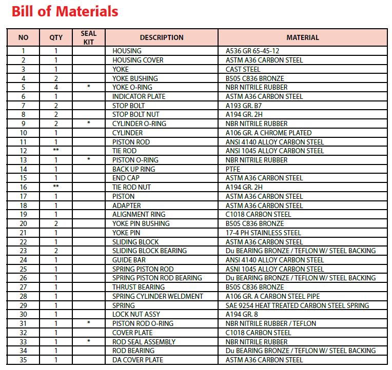
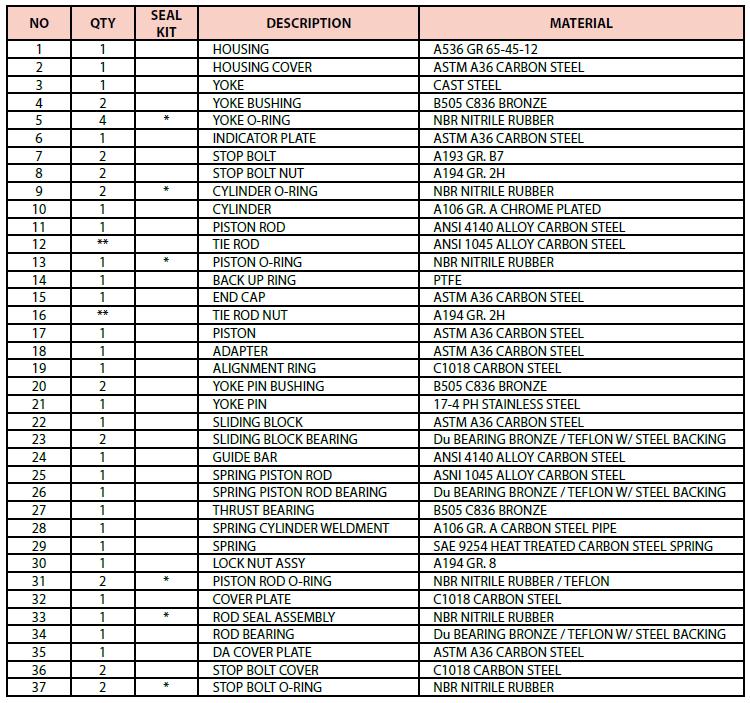
1 THD-SERIES S11DA280 THRU S27DA1020 & S11SR280 THRU S27SR1020 DOUBLE ACTING & SPRING RETURN SCOTCH YOKE ACTUATORS INTRODUCTION A-T Controls THD scotch yoke actuators have been designed and engineered to provide high cycle-life to meet the demands of our customers. The actuators are equipped with dual travel stops and accessory mounting.!!!warning!!! FOR YOUR SAFETY, IT IS IMPORTANT THAT BEFORE REMOVING ANY COMPONENTS OF THE ACTUATOR, ENSURE THAT ALL PNEUMATIC AND ELECTRICAL SUPPLIES ARE DISCONNECTED AND LOCKOUT AND TAGOUT PROCEDURES ARE IMPLEMENTED. PLEASE CONSULT FACTORY IF YOU HAVE ANY QUESTIONS ON ANY OF THE PROCEDURES LISTED BELOW. TABLE OF CONTENTS SECTION DESCRIPTION 1 INSTALLATION OF ACTUATOR 2 AIR SUPPLY 3 LUBRICATION 4 STORAGE OF ACTUATORS/ INFREQUENTLY CYCLED 5 DOUBLE ACTING OPERATION 6 SPRING RETURN OPERATION 7 TRAVEL ADJUSTMENT 8 REPLACEMENT OF CYLINDER SEALS 9 CONVERTING FROM DOUBLE ACTING TO SPRING RETURN 10 CONVERTING FROM FAIL CLOSED TO FAIL OPEN 11 SEAL KIT AND REPAIR PARTS 12 BILL OF MATERIALS 1. Installation of Actuator Triac actuators are adapted to the valve by means of an intermediate bracket and coupler. The coupler adapts the output of the actuator to the valve shaft. Standard mounting kits provide for mounting the actuator in the direction of the pipe. If different orientations are required please consult the factory when the order is placed. Before mounting the actuator on the valve insure that both units are in the proper orientation, i.e. both units open or closed. Make sure the coupler fits into the actuator and onto the valve before assembly. Also check the bracket for proper fit. After mounting the actuator, it may be necessary to adjust the travel stops for proper open and closed valve position. Always consult the manufactures installation manual for specific details before proceeding. Pneumatically stroke the actuator several times to assure smooth proper operation Air Supply Pneumatic piping to the actuator and associated accessories should follow the best practices for instrument pneumatic piping systems, I.E. lines free of water, oil, pipe sealant or other contaminants. The operating medium is to be filtered dry air or inert gas which is filtered to 50 micron particles size or less. It is extremely important that the actuator be powered with the proper air pressure and air volume. Maximum working pressure is 100 PSI. Consult the THD series catalog for a complete listing of MOP (maximum operating pressure) and MAWP (Maximum Allowable Working Pressure) Spring return actuators are vented to the atmosphere through the front flange. The Pressure Cylinder must be purged if a corrosive atmosphere exists. Please contact Triac Controls for possible solutions if this condition exists. 3. Lubrication Triac actuators are factory lubricated for life and additional lubrication is not normally required. However, for actuators performing 100,000 cycles or more, an oil mist lubricator is recommended. Oil mist lubrication requires a mineral oil type ISO VG32 Class 1 for usage in temperature range 15 to 158 Deg. F. Oil mist lubricator must be set to the lowest setting. Once begun, the oil mist lubrication cannot be discontinued. CAUTION If the actuator is equipped with a pneumatic positioner or pneumatic controller, oil mist lubricated air cannot be used unless the instrument manufacturer indicates that the instrument is compatible with lubricated air. 4. Actuators in Storage or infrequently cycled. Actuators in storage should be kept dry and protected from adverse conditions until installed. Original port protectors must be kept in the ports during storage. Actuators must be cycled every 90 days in storage or in operation. Actuators that do not cycle in 90 days should have a provision to jog the actuator to check for operation if a full cycle cannot be achieved. 5. Double Acting Operation Applying air pressure to the CCW Port drives the piston toward the front flange which turns the yoke counterclockwise when viewed from the accessory side of the actuator. When pressure is applied to the CW Port the piston is driven towards the end cap which turns the yoke clockwise. This is shown in Figure 1 1 September 25, 2015
2 supply must be removed before the stop bolt can be turned. Next loosen the hex nut and then position the stop bolt in or out to the correct position. Use care not to damage the o-ring seal. Retighten lock nut and replace stop bolt cap. CCW PORT CW PORT CLOCKWISE STOP BOLT COUNTER-CLOCKWISE STOP BOLT Figure 1 6. Spring Return Operation Applying air pressure to the CCW Port drives the piston toward the adapter as the spring is compressed. This rotates the yoke counterclockwise when viewed from the accessory side of the actuator. When pressure is relieved at the CCW Port the spring drives the piston towards the end cap which turns the yoke clockwise. This is shown in figure 2. To reverse the failure mode the spring and pressure cylinder are swapped end for end. Figure 3!!!WARNING!!! FOR YOUR SAFETY, IT IS IMPORTANT THAT BEFORE REMOVING ANY COMPONENTS OF THE ACTUATOR, ENSURE THAT ALL PNEUMATIC AND ELECTRICAL SUPPLIES ARE DISCONNECTED AND LOCKOUT AND TAGOUT PROCEDURES ARE IMPLEMENTED. CCW PORT CW PORT 8. Replacement of Cylinder Seals When the cylinder seals must be replaced, because of leakage or a preventive scheduled maintenance, the following procedure must be followed. Note only the soft parts indicated on pages 5 and 6 are included in a seal kit. If additional parts are required they must be ordered separately. Figure 2 7. Travel Adjustment The Triac THD actuators have + or - 8 degree adjustment of the end of travel stops in both the open and close directions. CAUTION: DO NOT ATTEMPT TO ADJUST STOP BOLT WITH AIR PRESSURE OR SPRING FORCE APPLIED TO THE STOP BOLT. ALWAYS JOG ACTUATOR AWAY FROM STOP BOLT BEFORE ADJUSTING. On models S11 thru S13 the stop bolts are in the center body of the actuator. Figure 3 shows the stop bolt locations for the S11 thru S13. On models S16 thru S27 the stop bolts are located in the end caps / end plates. The stop bolt on the end cap is for Closed (clockwise rotation) and the stop bolt on the spring cylinder / end plate is the Open (counterclockwise) rotation. Loosen and remove the stop bolt cap first. The air Due to the continuing improvement of the Heavy Duty Actuators, seal kits provided by A-T Controls may contain extra o-rings so that all revisions of the actuators are able to be repaired. When disassembling the actuator, it is recommended to match the old o-ring with the new o-ring from the repair kit by comparing the o-ring diameter and cross section. 1. Disconnect electrical supplies and shut off pneumatic supply, vent actuator and remove from valve or damper. 2. For spring return actuators the spring tension must be relieved before starting. Apply air pressure until the piston moves off the stop bolt. Remove the stop bolt cap (item 36) then loosen the hex nut (item 8) then back out the stop bolt (item7) until the preload is relieved. Do not remove the stop bolt with air pressure in the cylinder. For 2 September 25, 2015
3 double acting units the actuator should be in the clockwise position with the piston next to the end cap. 3. Vent all air pressure from the cylinder (item 10). 4. Remove the stop bolt, flat washer and seal (item 7, 8, 37). 5. Remove the tie rod nuts (item 16) from the tie rods (item 12). 6. Remove the end cap (item 15) from the cylinder (item 10). 7. Remove the cylinder from the adapter (item 18) by pulling over the piston (item 17). Use caution not to scratch the cylinder bore when sliding over piston. 8. Bend the safety tab on the lock nut retainer up and out of the groove. Remove the outer hex nut (item 30) holding the piston on the piston rod (item 11). Then remove the safety tab and then loosen and remove the inner nut. 9. Remove the piston, rod washer and o-ring (item 3). 10. Remove 2 each flat head screws in the adapter and remove the cover plate (item 32). 11. Remove the o-ring seal assembly (item 33) from the counter-bore. 12. Remove the o-rings from the piston and both flanges. 13. Clean all parts with a mild solvent that will not attack the coating on the parts. 14. The center body assembly should be inspected before the pressure group is rebuilt. 15. Remove the indicator plate bolts and remove indicator plate (item 6). 16. Remove the cover bolts and clean out the jacking screw holes. Install a bolt into each jacking screw hole and alternately tighten the screws to bring the cover plate up so that it can be removed from the yoke bearing. 17. Inspect the bronze slider (item 20) for wear along with the slot in the yoke arm. 18. Inspect the upper yoke bearing (item 4) for wear. 19. Wipe out old grease and replace with new grease on all sliding surfaces. 20. Lightly grease new o-ring seal assembly (item 33) and install in adapter. Replace cover plate and install 2 each flat head socket cap screws. 21. Lightly grease the o-ring for the adapter and install in the groove. 22. Place rod washer on piston rod with countersink facing out toward the end cap. Lightly grease o-ring (item 31) and slide over piston rod. Slide piston over piston rod and install inner hex nut then keyed tab and outer locknut. Then align outer hex nut with locking tab and bend tab into slot. 23. Lightly grease piston grooves and install o-ring and backup strip. 24. Lightly grease cylinder completely on the inside surface and carefully slide over the piston until seated on the adapter. 25. Lightly grease the o-ring for the end cap and install in the groove. Place end cap over the tie rods and seat on the cylinder. 26. Reinstall the tie rod nuts and tighten in a diagonal pattern. 27. Reinstall the stop bolt, o-ring, flat washer and hex nut in the rear flange. Screw in to the approximate position for 90 degree operation. On models S11 and S13 make sure that stop bolts are fully retracted before air is applied with the cover plate removed. 28. To pressure test a double acting actuator proceed to the next step for a spring return go the step Connect 2 psig air to the adapter and cycle the actuator then connect to the end cap and cycle the actuator several times. 30. Apply 100 psig air to the adapter and check for leakage at the adapter/cylinder connection. Also check for rod seal leakage in the center body cavity. Place a flexible tube in the end cap NPT port and check for leakage across the piston by checking for bubbles in a cup of water. Relieve air pressure on cylinder. 31. Place a light coating of permantex blue on cover gasket and install. Place cover over the alignment pins and install bolts and tighten. Remove any excess gasket sealer after it is dry. 32. Apply 100 psig air to the end cap and check for leakage at the adapter/cylinder connection. Place a flexible tube in the adapter NPT port and check for leakage across the piston. Relieve air pressure on cylinder. 33. To pressure test a Spring Return unit the cover must be installed before any air pressure is applied to the unit. Refer to step 31 for information on applying cover. 34. After cover is installed apply supply pressure to the end cap and check for leakage at the end cap /cylinder connection and check for leakage across the piston by using the method in step 30 above. 35. Make any final adjustments on the end cap stop bolt and check for leakage. Install the stop bolt cover and tighten. On models S11 and S13 set the stop bolts at 90 degrees. 36. The actuator is now ready to return to service. 3 September 25, 2015
4 9. Converting from Double Acting to Spring Return!!!WARNING!!! FOR YOUR SAFETY, IT IS IMPORTANT THAT BEFORE REMOVING ANY COMPONENTS OF THE ACTUATOR, ENSURE THAT ALL PNEUMATIC AND ELECTRICAL SUPPLIES ARE DISCONNECTED AND LOCKOUT AND TAGOUT PROCEDURES ARE IMPLEMENTED. 1. Disconnect electrical supplies and shut off pneumatic supply, vent actuator and remove from valve or damper. 2. Remove the stop bolt cap on the end cap of the air cylinder and loosen the hex nut and back out the stop bolt. The stop bolt must be backed off so that when 10 psig of air is applied to the adapter there is no load on the stop bolt. 3. Remove the cover bolts and clean out the jacking screw holes. Install a bolt into each jacking screw hole and alternately tighten the screws to bring the cover plate up so that it can be removed from the yoke bearing. 4. Remove the end plate (item 35) also remove the stop bolt cover, hex nut and stop bolt as these will be used in the spring cartridge on models S16 thru S Remove the set screws holding the stop screw pad in the sliding block (item 22). 6. Remove the stop screw pad. 7. Install the spring pusher rod into the spring cartridge. 8. Place a light coat of blue permantex on the flange gasket and apply to the actuator. 9. Lift Spring Cartridge and slide spring pusher rod into access hole and into hole in the sliding block. 10. Install the 4 cap screws and lock washers provided with the spring cartridge. 11. Place a light coating of permantex blue on cover gasket and install. Place cover over the alignment pins and install bolts and tighten. Remove any excess gasket sealer after it is dry. 12. Install indicator plate and tighten bolts. 13. Install stop bolt and hex nut in rear of spring cartridge.(models S16 thru S27) 14. Apply air pressure and check for smooth operation. 15. Adjust both stop bolts as necessary for proper travel and check for leakage before installing stop bolt covers. 10. Changing from Spring Closed to Spring Open To convert from spring closed to spring open requires that the air cylinder be removed and the spring cartridge removed and placed on the opposite side of the actuator. Complete instructions for rebuilding the air cylinder are listed above along with instructions for installing the spring 11. Seal kits and Repair Parts To order replacement seal kits or spare parts please provide the following information: Actuator Model Number Serial Number Type of seal kit (Nitrile standard, low temperature, Viton Item Number, Description and quantity for repair parts. 4 September 25, 2015

5 5 September 25, 2015

6 6 September 25, 2015
7 A-T Controls product, when properly selected, is designed to perform its intended function safely during its useful life. However, the purchaser or user of A-T Controls products should be aware that A-T Controls products might be used in numerous applications under a wide variety of industrial service conditions. Although A-T Controls can provide general guidelines, it cannot provide specific data and warnings for all possible applications. The purchaser / user must therefore assume the ultimate responsibility for the proper sizing and selection, installation, operation, and maintenance of A-T Controls products. The user should read and understand the installation operation maintenance (IOM) instructions included with the product, and train its employees and contractors in the safe use of A-T Controls products in connection with the specific application. While the information and specifications contained in this literature are believed to be accurate, they are supplied for informative purposes only. Because A-T Controls is continually improving and upgrading its product design, the specifications, dimensions and information contained in this literature are subject to change without notice. Should any question arise concerning these specifications, the purchaser/user should contact A-T Controls. For product specifications go to A-T Controls, Inc International Boulevard, Cincinnati, OH Phone: (513) Fax: (513) September 25, 2015
SY-SERIES S04DA75 THRU S06DA180 & S04SR75 THRU S06SR180 DOUBLE ACTING & SPRING RETURN SCOTCH YOKE ACTUATORS
 SY-SERIES S04DA75 THRU S06DA180 & S04SR75 THRU S06SR180 DOUBLE ACTING & SPRING RETURN SCOTCH YOKE ACTUATORS INTRODUCTION A-T Controls SY scotch yoke actuators have been designed and engineered to provide
RACK & PINION ACTUATORS 2R40 to 2R1750 Series Installation & Maintenance Manual
 TRIAC 2R Series Actuators: Attention: Instructional videos on some of the information provided below can be found on our website (http://www.a-tcontrols.com/videos/). Description Section Installation of
V-SEGMENT SERIES V-Port Segment Control Valves (VS/VV/VM) Installation & Maintenance Manual
 Installation & Maintenance Manual") CAUTION: 1. For your safety read this manual before installation or servicing. 2. Before installing or servicing, please ensure the line pressure has been relieved, and any hazardous fluids have been drained
CAUTION: 1. For your safety read this manual before installation or servicing. 2. Before installing or servicing, please ensure the line pressure has been relieved, and any hazardous fluids have been drained
Power-Seal High Performance Butterfly Valve: Series P1 Installation & Maintenance Manual
 CAUTION: 1. For your safety read this manual completely before installation or servicing. 2. Before installing or servicing, please ensure the line pressure has been relieved, and any hazardous fluids
Valtek Spring Cylinder Linear Actuators
 Valtek Linear Actuators GENERAL INFORMATION The following instructions are designed to assist in installing, troubleshooting and servicing Valtek spring cylinder actuators. Product users and maintenance
OpTK. Product Instruction Manual. Spring Cylinder Rotary Actuators INTRODUCTION SAFETY INFORMATION INSTALLATION. Leading Technologies For Control
 Leading Technologies For Control Product Instruction Manual OpTK Spring Cylinder Rotary Actuators TABLE OF CONTENTS INTRODUCTION Safety Information... pg. 1 Unpacking... pg. 1 INSTALLATION... pg. 1 PREVENTIVE
Installation Instructions
 Installation Instructions CPM Series Dual, cartridge mounted, flexible stator pusher seal designed for general service applications CPM PP Experience In Motion Description The CPM PP seal is a cartridge
MERIDIAN, 2 or 3 PIECE, TRUNNION MOUNTED BALL VALVES
 INSTALLATION, OPERATION AND MAINTENANCE INSTRUCTIONS MERIDIAN, 2 or 3 PIECE, TRUNNION MOUNTED BALL VALVES Size Range 2 48 ASME Classes 150-2500 *It is recommended that the valve installer is familiar with
Solenoid Block Kit for Series 90 Modular Accessory System Installation, Operation and Maintenance Instructions
 WCAIM2043 (Part 18460) Solenoid Block Kit for Series 90 Modular Accessory System Installation, Operation and Maintenance Instructions INTRODUCTION Note: For M.A.S. housing assembly, installation, and maintenance
Installation Instructions
 Installation Instructions Dual Gas Barrier Seals GB-200, GF-200, GX-200, and BufferPac Experience In Motion 1 Equipment Check 1.1 Follow plant safety regulations prior to equipment disassembly: Lock out
Disassembly and Reassembly for CBB-SR (Spring Return) Series Pneumatic Actuators
 Series Pneumatic Actuators") Part Number: VA001-196-31, Rev. 0 Release: May 2012 Disassembly and Reassembly for CBB-SR (Spring Return) Series Pneumatic Actuators Table of Contents Part Number: VA001-196-31, Rev. 0 May 2012 Table of
Part Number: VA001-196-31, Rev. 0 Release: May 2012 Disassembly and Reassembly for CBB-SR (Spring Return) Series Pneumatic Actuators Table of Contents Part Number: VA001-196-31, Rev. 0 May 2012 Table of
Fisher 2052 Diaphragm Rotary Actuator
 Instruction Manual 2052 Actuator Fisher 2052 Diaphragm Rotary Actuator Contents Introduction... 1 Scope of Manual... 1 Description... 1 Specifications... 4 Installation... 4 Actuator Mounting and Changing
ONYX VALVE CO MODEL CAR, CAP-PFO Installation & Maintenance
 ONYX VALVE CO MODEL CAR, CAP-PFO Installation & Maintenance OPERATION: (4-2010) The Onyx series CAR-PFO and CAP-PFO pinch valves fail open on loss of air. The simple spring and air bag arrangement drives
BETTIS SERVICE INSTRUCTIONS DISASSEMBLY AND REASSEMBLY FOR CB-SR-S SEISMIC SPRING RETURN SERIES PNEUMATIC ACTUATORS
 BETTIS SERVICE INSTRUCTIONS DISASSEMBLY AND REASSEMBLY FOR CB-SR-S SEISMIC SPRING RETURN SERIES PNEUMATIC ACTUATORS PART NUMBER: 102264 REVISION: "C" DATE: November 2000 Page 1 of 11 1.0 INTRODUCTION 1.1
aero 2 -IOM aero 2 ACTUATOR - INSTALLATION, OPERATION & MAINTENANCE MANUAL
 Instruction DP00226 May 2015 IMPORTANT SAFETY WARNINGS A. Before carrying out any repair or maintenance on the actuator, make sure that the pressure supply lines and electrical connections have been safely
Valtek Flow Boosters
 Valtek Flow Boosters GENERAL INFORMATION This bulletin is designed to assist in installing, adjusting, troubleshooting, and performing maintenance as required for the Valtek Flow Booster. Product users
AV INSTALLATION, OPERATION & MAINTENANCE MANUAL
 Rack & Pinion Pneumatic Actuators AV INSTALLATION, OPERATION & MAINTENANCE MANUAL AVCS PO Box 68172 Minneapolis, MN 55418 TABLE OF CONTENTS CHAPTER 1: PRODUCT DESCRIPTION 3 CHAPTER 2: TECHNICAL FEATURES
Series 72 Electri-SAFE On/Off Operation Including CLC Option Installation, Operation and Maintenance Instructions
 WCAIM2049 (Part 18960) Series 72 Electri-SAFE On/Off Operation Including CLC Option Installation, Operation and Maintenance Instructions Series 72 actuators are electro-hydraulic quarterturn valve actuators.
Installation Instructions
 Installation Instructions X-100 Single cartridge mounted welded metal bellows seal Experience In Motion Congratulations You have just purchased a reliable, long-life product manufactured by the leading
IOM FOR DYNATORQUE D-LOCK LOCKING DEVICE (DL TYPE)
") Scope: It is the purpose of this document to provide general installation, operation, and maintenance instructions for the DYNATORQUE D-Lock locking device. Design: All Cameron DYNATORQUE operators and
Scope: It is the purpose of this document to provide general installation, operation, and maintenance instructions for the DYNATORQUE D-Lock locking device. Design: All Cameron DYNATORQUE operators and
SERVICE INSTRUCTIONS ASSEMBLY & DISASSEMBLY T50X DOUBLE ACTING HYDRAULIC SERIES ACTUATORS
 Page 1 of 7 SERVICE INSTRUCTIONS ASSEMBLY & DISASSEMBLY T50X DOUBLE ACTING HYDRAULIC SERIES ACTUATORS INTRODUCTION This service procedure is offered as a guide to enable general maintenance to be performed
BETTIS ACTUATOR & CONTROLS SERVICE INSTRUCTIONS FIELD CONVERSION OF SPRING CARTRIDGE FAIL DIRECTION CLOCKWISE TO COUNTER-CLOCKWISE OR THE INVERSE
 BETTIS ACTUATOR & CONTROLS SERVICE INSTRUCTIONS FIELD CONVERSION OF SPRING CARTRIDGE FAIL DIRECTION CLOCKWISE TO COUNTER-CLOCKWISE OR THE INVERSE FOR THE FOLLOWING SERIES T3XX-SRX AND T4XX-SRX SPRING RETURN
ONYX VALVE CO MODEL DAO-PFC Installation & Maintenance
 ONYX VALVE CO MODEL DAO-PFC Installation & Maintenance OPERATION: (4-2010) The Onyx DAO-PFC pinch valve is an open frame valve without housing enclosure and fails closed on loss of air. The actuator drives
GH-BETTIS SERVICE INSTRUCTIONS DISASSEMBLY & REASSEMBLY FOR MODELS HD521-M4, HD721-M4 AND HD731-M4 DOUBLE ACTING SERIES PNEUMATIC ACTUATORS
 GH-BETTIS SERVICE INSTRUCTIONS DISASSEMBLY & REASSEMBLY FOR MODELS HD521-M4, HD721-M4 AND HD731-M4 DOUBLE ACTING SERIES PNEUMATIC ACTUATORS WITH HYDRAULIC CONTROL PACKAGE PART NUMBER: SE-023 REVISION:
Cylinder Maintenance & Repair Instructions
 Cylinder Maintenance & Repair Instructions PENINSULAR CYLINDER CO. Model HP High Pressure Hydraulic Cylinders Proximity Switch & Non Proximity Switch Designs - High Pressure NFPA Hydraulic Cylinder ( 5,000
flowserve.com Limitorque LRP Limitorque Rack & Pinion Pneumatic Actuator
 flowserve.com Limitorque LRP Limitorque Rack & Pinion Pneumatic Actuator 1 LRP Limitorque Rack and Pinion Actuator Series Limitorque is the brand customers trust when safe, reliable and robust valve automation
Disassembly and Reassembly for CBB (Double Acting) Series Pneumatic Actuators
 Series Pneumatic Actuators") MECATORK S.A.S Release: May 2012 Disassembly and Reassembly for CBB (Double Acting) Series Pneumatic Actuators MECATORK S.A.S Table of Contents May 2012 Table of Contents Section 1: Introduction 1.1 General
MECATORK S.A.S Release: May 2012 Disassembly and Reassembly for CBB (Double Acting) Series Pneumatic Actuators MECATORK S.A.S Table of Contents May 2012 Table of Contents Section 1: Introduction 1.1 General
HYDRAULICS. TX420 & & lower. Hydraulic Tandem Pump Removal. 4. Remove the LH side panel (Fig. 0388).
.") TX420 & 425 240000299 & lower 4. Remove the LH side panel (Fig. 0388). Hydraulic Tandem Pump Removal Note: Cleanliness is a key factor in a successful repair of any hydraulic system. Thoroughly clean all
TX420 & 425 240000299 & lower 4. Remove the LH side panel (Fig. 0388). Hydraulic Tandem Pump Removal Note: Cleanliness is a key factor in a successful repair of any hydraulic system. Thoroughly clean all
Installation Instructions
 Installation Instructions TM Five Star Seal 80 Series Single, cartridge mounted, flexible stator pusher seal designed for general service applications 84 and 85 Experience In Motion Description The 84/85
DO NOT INSTALL, OPERATE, OR MAINTAIN AN ATI PRODUCT UNLESS TRAINED AND QUALIFIED IN PRODUCT AND ACCESSORY INSTALLATION, OPERATION AND MAINTENANCE.
 IOM Supplement IOMS003 ATI HO1/HO2 HYDRAULIC OVERRIDE Scope of Supplement This supplement is intended to assist those who are involved with the installation, operation and maintenance of ATI Linear Actuators
Fisher 685 Piston Actuator
 Instruction Manual 685 Piston Actuator Fisher 685 Piston Actuator Contents Introduction... 1 Scope of Manual... 1 Description... 1 Specifications... 2 Educational Services... 3 Principle of Operation...
Installation, Operation and Maintenance Instructions Series 608 Ball Valve
 b. With valve open, remove three body bolts, loosen fourth and swing out body. Remove fourth bolt and spread pipe ends Close valve, remove ball, seats, body seals. Return body to its original position
ONYX VALVE CO MODEL DAO-ADA Installation & Maintenance
 ONYX VALVE CO MODEL DAO-ADA Installation & Maintenance OPERATION: (4-2010) The Onyx DAO-ADA pinch valve is an open frame valve without housing enclosure and fails last position on loss of air. This actuator
USER INSTRUCTIONS. Valtek Control Products Spring Cylinder Linear Actuators. Installation Operation Maintenance. Experience In Motion
 USER INSTRUCTIONS Valtek Control Products Linear Actuators FCD VLENIM0002-00-AQ - 10/14 (Replaces VLAIM002) Installation Operation Maintenance Experience In Motion 2 GENERAL INFORMATION The following instructions
LOW PRESSURE BALANCED VALVE DIAPHRAGM BALANCED
 DIAPHRAGM BALANCED All Rights Reserved. All contents of this publication including illustrations are believed to be reliable. And while efforts have been made to ensure their accuracy, they are not to
Fisher 3024C Diaphragm Actuator
 Instruction Manual 3024C Actuator Fisher 3024C Diaphragm Actuator Contents Introduction... 1 Scope of Manual... 1 Description... 2 Specifications... 3 Installation... 5 Mounting the Actuator on the Valve...
Installation Instructions
 Installation Instructions BW Seals RIS Seal Rubber in shear slurry seal Experience In Motion 1 Equipment Check 1.1 Follow plant safety regulations prior to equipment disassembly: lock out motor and valves.
Flowserve Spring Diaphragm Rotary Actuators
 Flow Control Division Installation, Operation, Maintenance Instructions Flowserve Spring Diaphragm Rotary Actuators TERMS CONCERNING SAFETY The safety terms DANGER, WARNING, CAUTION and NOTE are used in
ONYX VALVE CO MODEL DAC-PFO Installation & Maintenance
 ONYX VALVE CO MODEL DAC-PFO Installation & Maintenance OPERATION: (01-10) The Onyx series DAC-PFO pinch valve fails open on loss of air. This simple spring and air bag arrangement that drives a pair of
Valtek VL-HC Spring Cylinder Linear Actuators
 Valtek VL-HC Spring Cylinder Linear Actuators GENERAL INFORMATION The following instructions are designed to assist in installing, troubleshooting and servicing Valtek VL-HC spring cylinder actuators.
Installation Instructions
 Installation Instructions BW Seals Q, QB Series General Service Balanced Pusher Seal Q, QB, QBQ, QBS, QBU, QBQ LZ Experience In Motion 1 Equipment Check 1.1 Follow plant safety regulations: lock out motor
Baumann Sanitary Diaphragm Angle and Inline Control Valve
 Instruction Manual 84000 Valve Baumann 84000 Sanitary Diaphragm Angle and Inline Control Valve Contents Introduction... 1 Scope of Manual... 1 Safety Precautions... 2 Maintenance... 2 Flow Direction...
Fisher 1052 Size 20 Diaphragm Rotary Actuator with F and G Mounting Adaptation
 Instruction Manual 1052 Size 20 Actuator (F & G) Fisher 1052 Size 20 Diaphragm Rotary Actuator with F and G Mounting Adaptation Contents Introduction... 1 Scope of manual... 1 Description... 1 Specifications...
Fisher 657 Diaphragm Actuator Sizes and 87
 Instruction Manual 657 Actuator (30-70 and 87) Fisher 657 Diaphragm Actuator Sizes 30 70 and 87 Contents Introduction... 1 Scope of Manual... 1 Description... 2 Specifications... 2 Installation... 3 Mounting
GH-BETTIS OPERATING & MAINTENANCE INSTRUCTIONS DISASSEMBLY & ASSEMBLY FOR THE T80X-M4-S DOUBLE ACTING SERIES HYDRAULIC ACTUATORS
 GH-BETTIS OPERATING & MAINTENANCE INSTRUCTIONS DISASSEMBLY & ASSEMBLY FOR THE T80X-M4-S DOUBLE ACTING SERIES HYDRAULIC ACTUATORS -S INDICATES CYLINDERS ARE IN TANDEM PART NUMBER: 100121 REVISION "A" ECN
Installation, Operation, and Maintenance Manual for Milwaukee Valve
 Installation, Operation, and Maintenance Manual for Milwaukee Valve RACK AND PINION PNEUMATIC ACTUATORS TABLE OF CONTENTS I. Introduction... 04 A. Storage... Pg.04 II. Identification... 05 A. General Identification...
Fisher 1061 Pneumatic Piston Rotary Actuator with Style F & G Mounting Adaptations
 Instruction Manual 1061 F & G Actuator Fisher 1061 Pneumatic Piston Rotary Actuator with Style F & G Mounting Adaptations Contents Introduction... 1 Scope of Manual... 1 Description... 2 Specifications...
PNEUMATIC SLIDING VALVE
 INSTALLATION, OPERATION, & #: MM-SV001 6-23-09 Rev. A Page 1 of 8 PNEUMATIC SLIDING VALVE PART NUMBERS (Including, but not inclusive) SV704MSTS, SV714MSTS, SV754MSTS, SV764MSTS, SV774MSTS, SV706MSTS, SV716MSTS,
Model DF233 Control Valve
 Figure 1 DF233 Control Valve TABLE OF CONTENTS Introduction 2 Body and Packing Reassembly 7 Specifications 3 Fail Closed Actuator Reassembly 8 Valve Sizes 3 Fail Open Actuator Reassembly 9 Unpacking 4
ONYX VALVE CO MODEL DAO-PFO Installation & Maintenance
 ONYX VALVE CO MODEL DAO-PFO Installation & Maintenance OPERATION: (4-2010) The Onyx DAO-PFO pinch valve is an open frame valve without housing enclosure and fails open on loss of air. The actuator drives
Spring Return and Double Acting Pneumatic Quarter-turn Actuators Operations Manual
 Spring Return and Double Acting Pneumatic Quarter-turn Actuators Operations Manual Table of Contents General..................... 1 Pneumatic Recommendations... 1 Construction................. 2 Disassembly
Valtek Auxiliary Handwheels and Limit Stops
 Valtek Auxiliary s and Limit Stops Table of Contents Page 1 General information 2 Installation 2 Side-mounted handwheels, size 25 and 50 (linear actuators) 3 Side-mounted handwheels, size 100 and 200 (linear
CVS Series 35, 50, 60, 70. Scotch Yoke Hydraulic Actuators. Introduction. Instruction Manual
 Instruction Manual Figure 1: CVS Series 35 SRM100 Actuator CVS Series 35, 50, 60, 70 Scotch Yoke Hydraulic Actuators Introduction The CVS Hydraulic Actuator uses a scotch yoke mechanism to convert linear
INSTALLATION, OPERATION & MAINTENANCE MANUAL
 Rack & Pinion Pneumatic Actuators INSTALLATION, OPERATION & MAINTENANCE MANUAL QSM, Inc. 127 Village Lane Easley, SC 29642 U.S.A. Ph: (864) 605-0150 Fax: (864) 605-0830 www.tru-flo.com TABLE OF CONTENTS
TBV OPERATION AND MAINTENANCE MANUAL SERIES 1800: FLANGED BALL VALVE. For technical questions, please contact the following:
 TBV OPERATION AND MAINTENANCE MANUAL SERIES 1800: FLANGED BALL VALVE For technical questions, please contact the following: Engineering Department 1537 Grafton Road Millbury, MA 01527 Phone: (508) 887-9400
Installation and Operating Manual
 . Installation and Operating Manual WE/XE-690, 1350, 1700, 2640, 4400, 5200, 6900, 10500 17500, 25690 1 (Rev. 020113) IOM8011.docx . Table of Contents Introduction Page Safety Instructions..... 3 Introduction
Operation and Maintenance Instructions for Bettis GVO-C Series GVO-CLP-SR Pneumatic Actuators
 Part Number: GVO-CLP-SR.IOM.1003, Rev. 0 Release: March 2016 Operation and Maintenance Instructions for Bettis GVO-C Series GVO-CLP-SR Pneumatic Actuators Part Number: GVO-CLP-SR.IOM.1003, Rev. 0 Table
IOM Manual. IOM Manual. Series 20/21.
 IOM Manual IOM Manual Series 20/21 www.flowlinevalves.com Flow Line Valve and Controls, L.L.C. 110 Main Project Road Schriever, LA 70395 P.O. Box 677 Schriever, LA 70395 Phone 985-414-6004 * Toll Free
Fisher 1051 and 1052 Style H and J Sizes 40, 60 and 70 Rotary Actuators
 Instruction Manual 1051 and 1052 H & J Actuators Fisher 1051 and 1052 Style H and J Sizes 40, 60 and 70 Rotary Actuators Contents Introduction... 1 Scope of Manual... 1 Description... 2 Specifications...
ONYX VALVE CO MODEL CER and CEP Installation & Maintenance
 ONYX VALVE CO MODEL CER and CEP Installation & Maintenance OPERATION: ( 01-10 ) The Onyx series CER and CEP are electric operated pinch valves. They fail in last position on loss of electric power. The
USER INSTRUCTIONS. NAF Trunnball DL Ball Valves. Installation Operation Maintenance. Experience In Motion FCD NFENIM A4 01/15
 USER INSTRUCTIONS NAF Trunnball DL Ball Valves FCD NFENIM4168-01-A4 01/15 Installation Operation Maintenance Experience In Motion Contents SAFETY 3 1 General 3 2 Lifting 4 3 Receiving Inspection 4 4 Installation
Installation Instructions
 Installation Instructions ISC2 Series Innovative Standard Cartridge seal designed for general purpose applications. 1 Equipment Check 1.1 Follow plant safety regulations prior to equipment disassembly:
Baumann Sanitary Angle Control Valve
 Baumann 83000 Sanitary Angle Control Valve Contents Introduction... 1 Scope of Manual... 1 Safety Precautions... 2 Educational Services... 2 Maintenance... 3 Installation... 3 Air Piping... 4 Flow Direction...
REPAIR PROCEDURES MANUAL
 REPAIR PROCEDURES MANUAL PVX Series Vane Pumps A Design Series Step-by-Step Guide to Troubleshooting and Repairing PVX Series Vane Pumps Introduction Thank you for choosing Continental Hydraulics PVX Vane
Baumann Mikroseal Control Valve
 Instruction Manual 81000 Valve Baumann 81000 Mikroseal Control Valve Contents Introduction... 1 Scope of Manual... 1 Safety Precautions... 2 Maintenance... 3 Installation... 3 Air Piping... 4 Flow Direction...
Model DFR 026 Rotary Actuator
 Figure DFR 026 and 57 Control Valve TABLE OF CONTENTS General 2 Actuator Assembly 4 Scope 2 Bushing Installation 4 Principles of Operation 2 Mounting Yoke / Hub Assembly 4 Safety Caution 2 Spring / Adjuster
Installation Instructions
 Installation Instructions Durametallic Double CRO Dual single coil spring friction drive for applications with water lubrication properties 1 Equipment Check 1.1 Follow plant safety regulations prior to
Fisher 1061 Pneumatic Piston Rotary Actuator with Style H & J Mounting Adaptations
 Instruction Manual 1061 H & J Actuator Fisher 1061 Pneumatic Piston Rotary Actuator with Style H & J Mounting Adaptations Contents Introduction... 1 Scope of Manual... 1 Description... 2 Specifications...
USER INSTRUCTIONS. Installation Operation Maintenance. NAF Setball SF Ball Sector Valves. Experience In Motion FCD NFENIM A4 09/16
 USER INSTRUCTIONS NAF Setball SF Ball Sector Valves FCD NFENIM4156-00 A4 09/16 Installation Operation Maintenance Experience In Motion Contents SAFETY 3 1 General 3 2 Lifting 4 3 Receiving Inspection 4
CENTAC Inlet and Bypass Valve Positioners
 CENTAC Inlet and Bypass Valve Positioners INGERSOLL-RAND AIR COMPRESSORS INLET AND BYPASS VALVE POSITIONERS Copyright Notice Copyright 1992, 1999 Ingersoll-Rand Company THIS CONTENTS OF THIS MANUAL ARE
Installation & Operation Manual
 Installation & Operation Manual (I-TORK PDS Series Pneumatic Actuator) PDS-M0108/1010 74-6, Chun Ui-Dong, Won Mi-Gu, Bucheon, Kyoung Ki-Do, Korea Tel : 82-2-855-1365, 66 Fax : 82-2-855-1367 E-mail : roy75@i-tork.com
I-795/906. Series 795 and 906 Installation-Ready Knife Gate Valves WARNING INSTALLATION AND MAINTENANCE INSTRUCTIONS
 INSTALLATION AND MAINTENANCE INSTRUCTIONS I-795/906 Series 795 and 906 Installation-Ready Knife Gate Valves HANDWHEEL OPERATOR PNEUMATIC OPERATOR HYDRAULIC OPERATOR WARNING Read and understand all instructions
Rotary Valve Maxflo + 60 and 80 Opening type NT
 Rotary Valve Maxflo + 60 and 80 Opening type NT TECHNICAL MANUAL 1- INSTALLATION 1.1 - Valve pipe-work layout 1.2 - Specification check 1.3 - Installing the valve in the piping 1.4 - Connection to control
SERIES M STANDARD FEATURES STANDARD OPTIONS. Double acting or spring return. Heavy duty housing, torque plug and piston rod design.
 Torque Plug Ductile Iron Thrust Pin Bearing Cast Iron Piston Rod Cylinder Tube Piston Ductile Iron Spring Retainer Ductile Iron Spring End Cap Ductile Iron Cover Housing Ductile Iron Adjustable Stops Spring
Bettis M11 Manual Hydraulic Override System Operating Instructions for HD, T, and G Series Pneumatic and Hydraulic Actuators
 Instruction Manual D102755X012 March 2010 Bettis M11 Bettis M11 Manual Hydraulic Override System Operating Instructions for HD, T, and G Series Pneumatic and Hydraulic Actuators The following instruction
STAINLESS STEEL SERIES LSSW HIGH PRESSURE HYDRAULIC CYLINDERS INSTALLATION & OPERATING INSTRUCTIONS
 CATALOG: LSSW-00 STAINLESS STEEL SERIES LSSW HIGH PRESSURE HYDRAULIC CYLINDERS INSTALLATION & OPERATING INSTRUCTIONS REMEMBER.... WHEN PERFORMANCE COUNTS SPECIFY LEHIGH LEHIGH FLUID POWER, INC. 1413 ROUTE
USER INSTRUCTIONS. Spring Diaphragm Rotary Actuators. Installation Operation Maintenance. Experience In Motion FCD VLAIM /12
 USER INSTRUCTIONS Spring Diaphragm Rotary Actuators FCD VLAIM050-01 05/12 Installation Operation Maintenance Experience In Motion Contents General Information 3 Unpacking 4 Installation 4 Changing Air
BR 31a Rack-and-pinion Actuator,
 Operating, assembly and maintenance instructions BR 31a Rack-and-pinion Actuator, SRP and DAP 1. General These instructions are intended to support the user in the assembly, maintenance, and repair of
Operation & Service Manual
 Operation & Service Manual Model: 02-1248-0112 12 Ton Single Stage Jack 11/2004 Rev. 02 Includes Illustrated Parts Lists 1740 Eber Rd Tronair, Inc. Phone: (419) 866-6301 Holland, OH 43528-9794 www.tronair.com
Operating & Maintenance Manual For Steam Conditioning Valve
 For Steam Conditioning Valve 1 Table of Contents 1.0 Introduction 3 2.0 Product description 3 3.0 Safety Instruction 4 4.0 Installation and Commissioning 5 5.0 Valve Disassembly 6 6.0 Maintenance 6 7.0
INSTALLATION, OPERATION, AND MAINTENANCE MANUAL WELKER INJECTION PUMP
 INSTALLATION, OPERATION, AND MAINTENANCE MANUAL WELKER INJECTION PUMP MODEL SSO-8 DRAWING NUMBERS AD148CF AD148CG AD148CO AD148CQ AD500CA MANUAL NUMBER IOM-065 REVISION Rev. A, 8/17/2016 TABLE OF CONTENTS
DeZURIK DR 40B ROTARY DIAPHRAGM ACTUATOR
 DR 40B ROTARY DIAPHRAGM ACTUATOR Instruction D10506 October 2016 Instructions These instructions provide information about s. They are for use by personnel who are responsible for installation, operation
HIGH PRESSURE CONTROL VALVE PISTON BALANCED
 PISTON BALANCED All Rights Reserved. All contents of this publication including illustrations are believed to be reliable. And while efforts have been made to ensure their accuracy, they are not to be
Maintenance Instructions & Parts List
 Maintenance Instructions Actuators Maintenance Instructions & Parts List Provide Model Number and Serial Number When Ordering Spare Parts. General Limit the maximum operational pressure of the Parker M
CONTROL VALVES. Installation, Maintenance & Operating Instructions. Read these instructions carefully before installation or servicing.
 KOSO HAMMEL DAHL CONTROL VALVES KOSO HAMMEL DAHL 253 Pleasant Street West Bridgewater, MA 02379 tel: 774.517.5300 fax: 774.517.5230 www.hammeldahl.com Installation, Maintenance & Operating Instructions
Type 1035/El-O-Matic Rack-and-Pinion Rotary Actuator
 Instruction Manual 1035/El-O-Matic Actuator Type 1035/El-O-Matic Rack-and-Pinion Rotary Actuator Contents Introduction............................... 1 Scope of Manual......................... 1 Description..............................
Fisher 1052 Size 70 Diaphragm Rotary Actuator
 Instruction Manual 1052 Size 70 Actuators Fisher 1052 Size 70 Diaphragm Rotary Actuator Contents Introduction... 1 Scope of Manual... 1 Description... 3 Specifications... 3 Educational Services... 3 Installation...
I&M UT Series (2003 Design)
") I&M UT Series (2003 Design) 3170 Wasson Road Cincinnati, OH 45209 USA Phone 513-533-7340 ax 513-533-7343 E-Mail: marwin@richardsind.com www.marwinvalve.com Installation & Maintenance Instructions for Marwin
I&M UT Series (2003 Design) 3170 Wasson Road Cincinnati, OH 45209 USA Phone 513-533-7340 ax 513-533-7343 E-Mail: marwin@richardsind.com www.marwinvalve.com Installation & Maintenance Instructions for Marwin
Fisher 685SE and 685SR Piston Actuator
 Instruction Manual 685SE/685SR Piston Actuator Fisher 685SE and 685SR Piston Actuator Contents Introduction... 1 Scope of Manual... 1 Description... 1 Specifications... 2 Principle of Operation... 3 Installation...
DR Series Radial Diaphragm Valves
 DR Series Radial Valves Service Instructions Valves with Plastic Actuators (1/2 through 1 inch) Valves with Aluminum Actuators (1/2 through 2 inch) Manual model Pneumatic model Manual model Pneumatic model
Model DF269 Control Valve
 Figure 1 DF269 Control Valve TABLE OF CONTENTS Introduction 2 Fail Open Actuator Disassembly 6 General 2 Body and Packing Reassembly 7 Scope 2 Fail Closed Actuator Resassembly 8 Specifications 3 Fail Open
Model DFR 070/156/220 Rotary Actuator
 Figure 1 DFR 156 TABLE OF CONTENTS General 2 Actuator Assembly 18 Scope 2 Bushing / Yoke Assembly 18 Principles of Operation 2 Spring Barrel Assembly 18 Safety Caution 2 Diaphragm Plate Assembly 20 Specifications
PV4 - Compact Shut Off Style Pig Valve IOM - Installation, Operation & Maintenance
 ACECO Valve P.O. Box 9 Mounds, Oklahoma 74047 PV4 - Compact Shut Off Style Pig Valve IOM - Installation, Operation & Maintenance Doc. No.: IOM-PV4-.0 Date: 6/0-00 Revision: A Contents: Installation Operation
MTC Series. Double Acting and Spring Return Actuator and Accessories. MasterTorq. Pneumatic Actuators. Atex Class 2
 Double Acting and Spring Return Actuator and Accessories MTC Series TM Pneumatic Actuators Atex Class Operations Double Acting A B A B By supplying air to Port A, pressure is applied to the center chamber
Baumann Pneumatic Actuators
 Instruction Manual Baumann Pneumatic Actuators Baumann Pneumatic Actuators Contents Introduction... 1 Scope of Manual... 1 Design Notes... 2 Installation... 2 Attaching an Air-to-Retract (ATR) Actuator
ROTEX SERVICE INSTRUCTIONS FOR MODELS DRS SERIES DRSB TO DRSM PNEUMATIC ACTUATOR
 ROTEX SERVICE INSTRUCTIONS FOR MODELS DRS SERIES DRSB TO DRSM PNEUMATIC ACTUATOR REVISION: 0 DATE: OCT 2010 ROTEX CONTROLS Page 1 of 8 SECTION 1 - INTRODUCTION 1.1 GENERAL SERVICE INFORMATION 1.1.1 This
Flow Line Controls. Installation & Operations Manual SERIES 20/21 Pneumatic Actuators
 Flow Line Controls Installation & Operations Manual SERIES 20/21 Pneumatic Actuators Flow Line Controls, Inc. P.O. Box 677 Schriever, LA 70395 Phone: 985-414-6003 Toll Free 1-800-815-9226 Fax 985-414-6072
ONYX VALVE CO MODEL CER with JORDAN ACTUATOR Installation & Maintenance
 ONYX VALVE CO MODEL CER with JORDAN ACTUATOR Installation & Maintenance OPERATION: (7-2011) The Onyx series CER is electric operated pinch valve, with full round configuration and a single pinching mechanism.
INSTALLATION, OPERATION AND MAINTENANCE MANUAL (IOM)
") INSTALLATION, OPERATION AND MAINTENANCE MANUAL (IOM) IOM-1088 03-16 Model 1088 Vacu-Gard Blanketing Valve ISO Registered Company SECTION I I. DESCRIPTION AND SCOPE The Model 1088 Vacu-Gard is a tank blanketing
INSTALLATION, OPERATION AND MAINTENANCE MANUAL (IOM) IOM-1088 03-16 Model 1088 Vacu-Gard Blanketing Valve ISO Registered Company SECTION I I. DESCRIPTION AND SCOPE The Model 1088 Vacu-Gard is a tank blanketing
DeZURIK SPRING RETURN CYLINDER OPERATOR FOR G-SERIES ACTUATORS USED ON PEF 100% PORT ECCENTRIC VALVES
 SPRING RETURN CYLINDER OPERATOR FOR G-SERIES ACTUATORS USED ON PEF 100% PORT ECCENTRIC VALVES Instruction D10466 December 2012 Instructions These instructions provide information about s. They are for