Edelbrock Enforcer EFI Supercharger C.I.D. Small-Block Chevy
|
|
|
- Suzanna Jones
- 5 years ago
- Views:
Transcription

1 Photo may not represent actual product C.I.D. Small-Block Chevy 1986 and Earlier Style Heads: 1520, 1521, 15201, 15211, 15203, E-Tec and Vortec Style Heads: 1522, 1523, 15221, 15231, 15223, 15233
2 System C.I.D. Small-Block Chevrolet Installation Instructions Thank you for purchasing the Edelbrock Dual-Quad Enforcer Supercharger for the C.I.D. small-block Chevrolet engines. The Edelbrock Enforcer Supercharger utilizes Eaton s TVS2300 Supercharger rotors, which features a four lobe design with a full 160 of twist. This design offers quite operation, maximum air flow, minimal temperature rise and the reliability for which Eaton is known. These rotors however, are merely the foundation of the system. The Edelbrock Supercharger is a complete system that maximizes efficiency and performance by minimizing air restriction into and out of the supercharger. As a result, the Enforcer supercharger maximizes airflow with minimum temperature increases and minimum power consumption. This Dual-Quad Enforcer Supercharger will accept standard 4150-style bolt pattern throttle bodies. Base supercharger systems will not include the throttle bodies, electronics, harness or injectors. PART NUMBER FINISH APPLICATION DESCRIPTION INTRODUCTION 1520 Satin Enforcer TVS2300 Supercharger, Intercooled, Dual-Quad, Does Not Include Throttle Bodies, Electronics, Harness & Injectors 1521 Satin Enforcer TVS2300 Supercharger, Intercooled, Dual-Quad, Complete with Electronics Enforcer TVS2300 Supercharger, Intercooled, Dual-Quad, Does Not Include Throttle Polished Small-Block Chevy Bodies, Electronics, Harness & Injectors 1986 and Earlier Polished Enforcer TVS2300 Supercharger, Intercooled, Dual-Quad, Complete with Electronics Black Enforcer TVS2300 Supercharger, Intercooled, Dual-Quad, Does Not Include Throttle Bodies, Electronics, Harness & Injectors Black Enforcer TVS2300 Supercharger, Intercooled, Dual-Quad, Complete with Electronics 1522 Satin Enforcer TVS2300 Supercharger, Intercooled, Dual-Quad, Does Not Include Throttle Bodies, Electronics, Harness & Injectors 1523 Satin Enforcer TVS2300 Supercharger, Intercooled, Dual-Quad, Complete with Electronics Enforcer TVS2300 Supercharger, Intercooled, Dual-Quad, Does Not Include Throttle Polished E-Tec/Vortec Style Bodies, Electronics, Harness & Injectors Cylinder Heads Polished Enforcer TVS2300 Supercharger, Intercooled, Dual-Quad, Complete with Electronics Black Enforcer TVS2300 Supercharger, Intercooled, Dual-Quad, Does Not Include Throttle Bodies, Electronics, Harness & Injectors Black Enforcer TVS2300 Supercharger, Intercooled, Dual-Quad, Complete with Electronics The Edelbrock Enforcer supercharger is intended for c.i.d. small block Chevrolets equipped with long water pumps and stock style bracketry. It s designed to utilize the factory accessory drive belts, in conjunction with, the secondary 10 rib supercharger pulley drive system. As with any universal power add-ons, actual power outputs will vary depending on the application. Below is a general baseline with actual power numbers from testing. Please note that this is just a guideline used for reference only. Actual power and boost output will vary depending on your application. SPECIFICATIONS Displacement 350 C.I.D Compression 9.5 : 1 Block GM 4 Bolt Main w/ 1-Piece Rear Seal Pulley Size 4 Cylinder Heads Edelbrock E-Tec 200 #60985 Boost PSI *5 PSI ( in upper RPM) Camshaft Edelbrock Rollin Thunder #2205 Horsepower *519 hp Throttle Body Dual 1,000 CFM #38283 Torque *507 ft-lbs *Actual horsepower, torque and boost numbers will vary depending on application. Page 1
3 System C.I.D. Small-Block Chevrolet Installation Instructions TOOLS AND EQUIPMENT: Box and Open End Wrenches Socket Set Distributor Wrench Pliers Screw Drivers (Regular and Phillips) Torque Wrench Gasket Scraper Timing Light Vacuum Gauge Rags Water Bucket Paper and Pencil Masking Tape ADDITIONAL MATERIALS REQUIRED: High Volume Fuel Pump # psi, 3/8 hose barb inlet/outlet # psi, -10 AN inlet/outlet # psi, -12 AN inlet/outlet Fuel Pressure Regulator w/ Boost Reference # For Pro-Flo 2 and Pro-Flo XT systems # GPH w/ -6 AN inlets/bypass # GPH w/ -10 AN inlets and -6 AN bypass Fuel Fittings and Fuel Lines Low Temperature Radiator #15405: Full Face Universal Fit #15406: Compact Single Dual-Quad Air Cleaner Spark Plugs 2-3 heat ranges colder than plugs currently using in your naturally aspirated engine Throttle Brackets and Hardware Fuel Pump Block-off Plate Edelbrock Gasgacinch (#9300) Silicone Thread Sealer Loctite - Red, Blue, or Equivalent Radiator Coolant Page 2
, not your parts distributor.")

4 IMPORTANT WARNINGS Before beginning the installation, use the enclosed checklist to verify that all components are present in the box. Then inspect each component for damage that may have occurred in transit. If any parts are missing or damaged, contact Edelbrock Technical Support ( ), not your parts distributor. WARNING: Installation of this supercharger will result in a significant change to the performance characteristics of your vehicle. It is highly recommended that you take some time to familiarize yourself with the added power, and how it is delivered, in a controlled environment. Take extra care on wet and slippery roads, as the rear tires will be more likely to lose traction, with the added power. WARNING: Exposed fuel and oil will be present during this installation. When working around gasoline and/or oil, always work in a well ventilated area, and keep all open flames, sparks and other sources of ignition away from the work areas. Failure to do so can result in a fire and/or explosion Proper installation is the responsibility of the installer. Improper installation will void all manufacture s standard warranties and may result in poor performance and engine or vehicle damage. Successful operation of the engine with this supercharger kit requires a working knowledge of the set-up and tuning of an engine. This supercharger kit is capable of supporting over 500 HP. Aftermarket pistons, connecting rods, and valves are recommended to ensure engine durability. See the Boost and Ignition Timing section in this manual for further information. The valve lash or lifter preload should be properly adjusted. If the valves are not properly seating, or the valve lash is not properly adjusted, the increased temperatures created by the increased power output could accelerate valve seat wear and cause burnt valves. If for any reason your engine has oil pressure that is below the acceptable service limits as specified in the Factory Service Manual, this problem should be corrected before installing this supercharger kit. THIS EDELBROCK ENFORCER SUPERCHARGER WILL NOT WORK WITH HIGH ENERGY IGNITION (HEI) DISTRIBUTORS FUEL PUMP REQUIREMENTS: This supercharger requires significantly more fuel to properly operate when compared to naturally aspirated applications. A High Volume Fuel Pump is required. Please select one properly rated for your application (See page 3). AFTER INSTALLATION, BEFORE STARTING THE VEHICLE: The use of colder spark plugs are strongly recommend when installing a supercharger. In our testing, we used Champion RC9YC spark plugs, which are 2-3 heat ranges colder than the spark plugs used in a naturally aspirated engine. Any manufacturer s plugs that match the correct plug configuration for your application will be adequate. HOOD CLEARANCE: This supercharger is tall by design. An aftermarket hood and/or modifications to the hood may be required. Please make modifications before operating the vehicle. 91 octane or higher gasoline is required at all times. If your vehicle has been filled with anything less, it must be run until almost dry and refilled with 91 or higher octane gasoline twice prior to installation. Failure to use the required 91 octane gasoline or higher could permanently damage your engine. Any failures associated with not using premium 91 octane gasoline or higher, will be ineligible for warranty repairs. Page 3


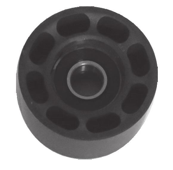

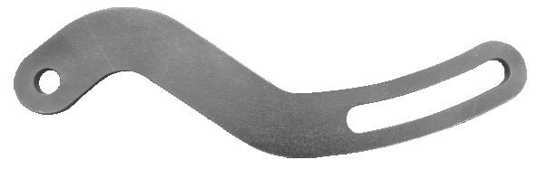

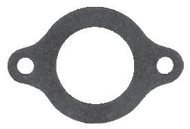

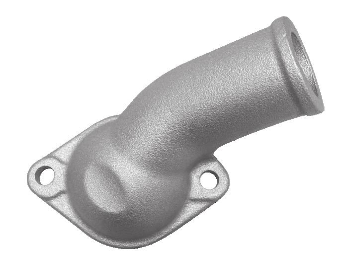

5 It is recommended that you check the Edelbrock Tech Center Website for any updates to this installation manual. Please refer to the lower left hand footer to verify that you have the latest revision of this installation manual before beginning the installation. Tech Center: Edelbrock Authorized Installer Disclaimer Authorized installers of Edelbrock products are independent companies over which Edelbrock has no right of control. Edelbrock LLC makes no claims regarding the abilities, expertise or competency of individual employees of any authorized installer. Each authorized installer is an independent company and makes its own independent judgments. Edelbrock LLC specifically disclaims any responsibility to any party including third parties for the actions, or the failure to act, of individuals, agents or a company authorized in the installation of Edelbrock LLC products. FEAD KIT CONTENT (parts not to scale) FEAD Bracket Waterneck Gasket Idler Pulley Waterneck Tensioner FEAD Spacer Alternator Bracket Page 4
 Page")
6 INTERCOOLER KIT (parts not to scale) Water Pump Recovery Tank w/ Cap Recovery Tank Bracket Water Pump Bracket Water Pump Bracket Strap 3/4 Hose (Qty 7 ) Page 5

 Washer 3/8 (Qty 12) 12 Pt Head 5/16-18 x 1.")
 Hex Flange M8 x 1.25 x 30mm Hex Flange M6 x 1.")
7 HARDWARE BAG 1 (parts not to scale) Hex Head 3/8-24 x 3.75 (Qty 3) Hex Head 7/16-20 x 2.75 Hex Flange 3/8-16 x 3.25 Hex Flange 5/16-18 x 2.00 Hex Flange 5/16-18 x 1.25 Socket Head 5/16-18 x 3.5 (Qty 2) Set Screw 5/16-18 (Qty1) Crank Pulley Shim (Qty 3) Washer 7/16 Washer 3/8 (Qty 3) Washer 5/16 (Qty 2) 45 Fitting Compact Hex 3/8-16 x 1 (Qty 12) Washer 3/8 (Qty 12) 12 Pt Head 5/16-18 x 1.75 (Qty 8) Washer 5/16 (Qty 8) 1520, 1521, 15201, 15203, & Kits Only 1522, 1523, 15221, 15223, & Kits Only Pulley Adapter HARDWARE BAG 2 (parts not to scale) Hex Flange M8 x 1.25 x 30mm Hex Flange M6 x 1.0 x 16mm (Qty 4) Hex Flange M6 x 1.0 x 12mm (Qty 3) 3/4 Hose Clamp (Qty 8) -12 AN Fittings (Qty 2) Page 6
8 INTERCOOLER PLUMBING DIAGRAM (parts not to scale) Page 7
9 PARTS REMOVAL AND PREPARATION These are general installation instructions for the Edelbrock Small Block Chevy Enforcer Supercharger. Removal and installation of factory components will differ from vehicle to vehicle. Please refer to your service manual for specific details on removal and installation of factory components if necessary. 1. Disconnect the negative battery terminal. 2. Drain the radiator coolant (drain plug will normally be located on lower right of radiator, facing the engine). 12. Note the position of distributor vacuum canister and place a mark on the valve cover (if applicable) or firewall that lines up with the vacuum outlet. These marks will be used as a reference points when reinstalling the distributor. However, re-alignment of the distributor may be required to clear the supercharger after installation. 13. Note the position of points (or magnetic trigger wheel). If open, how much; if closed, note the distance from point block to cam lobe (See Figure 1). Figure 1 3. Loosen the tension on the accessory belt(s) and remove belt(s). Remove the upper alternator tensioning bracket from the water pump. 4. Remove the crankshaft pulley bolts and remove the accessory pulley. Remove the crankshaft balancer bolt, but do not remove the balancer itself. 5. Remove the upper radiator hose, thermostat housing and thermostat, if mounted on the intake manifold. 6. Remove the gas cap to relieve fuel pressure. Disconnect the fuel line from carburetor and plug the fuel line to avoid excessive fuel drainage. Replace the gas cap. NOTE: Take note of all factory linkage locations. This will simplify the installation process. 7. Disconnect all linkages from carburetor such as throttle, throttle springs, transmission, cruise control and automatic choke. 8. Tag and remove all coil wires, sensor wires, and vacuum lines. This will simplify the installation process. 9. Remove any brackets installed on the intake manifold. 10. Depending on application, removal of valve cover bolts and/or valve covers may be required. Replace any worn out valve cover gaskets to prevent oil leaks. CAUTION: The following procedure must be followed carefully as serious damage to the engine can occur if the distributor is not removed and reinstalled correctly. NOTE: This Edelbrock Enforcer Supercharger will not work with High Energy Ignition (HEI) Distributors. 11. Remove distributor cap. Note position of rotor and make a mark on the distributor case that lines up with the rotor point. 14. Remove the distributor from the engine. Once the distributor has been removed, DO NOT rotate the engine as this will throw off the engine s timing. 15. Remove the intake manifold bolts and remove the intake manifold along with the carburetor (if applicable). 16. Remove the factory mechanical fuel pump and push rod, clean mating surface on engine block with scraper and lacquer thinner. NOTE: A fuel pump block-off plate (not included) is required to block-off the factory fuel pump hole. 17. Install block-off plate using the appropriate gasket and bolts. 18. THOROUGHLY clean the intake manifold bolt holes, cylinder head flanges, and end seal surfaces to remove all remaining gasket material and sealer. NOTE: To prevent gasket material from falling into the ports and combustion chambers lay rags in lifter valley and stuff paper towels or rags into the ports. 19. Using a shop vac, vacuum all the debris from the lifter valley, mating surfaces, bolt holes, etc. NOTE: Avoid using vacuums with metal tips as it can scratch the cylinder head surface. Also avoid using compressed air to blow the debris off as it can make its way into the block. 20. Once surfaces are clean, carefully remove all protective material from the ports and lifter valley. Using a rag and lacquer thinner, wipe down the gasket surfaces to remove any oil, grease or gasket residue. Page 8
. Then install the supplied 7/16-20 x 2.75 balancer bolt with a 7/16 washer and snug the bolt down until the pulley is flush.")
. Figure 5 5.")
 on the cylinder head surface and supercharger manifold to make sure they are correct. Beaded side of gasket faces up. 2.")
 minutes (See Figure 3). Figure 3 3. Within a few minutes, the Gasgacinch will become tacky to the touch.")

10 ENFORCER INSTALLATION PROCEDURE 1. Install the supercharger drive pulley in front of the factory crank pulley using the supplied 3/8-24 x 3.75 long hex head bolts and 3/8 washers (See Figure 2). Then install the supplied 7/16-20 x 2.75 balancer bolt with a 7/16 washer and snug the bolt down until the pulley is flush. Do not torque down the bolts at this time. Figure 2 4. With the intake gaskets in place, apply a thin layer of silicone, with your finger, around the water passages on the intake manifold (See Figure 5). Figure 5 5. Apply a 1/4 thick bead of silicone across each end seal surface (See Figure 6). Figure 6 NOTE: Check replacement intake manifold gaskets (included) on the cylinder head surface and supercharger manifold to make sure they are correct. Beaded side of gasket faces up. 2. Apply two (2) thin layers of Gasgacinch (#9300) to the cylinder head s mating surfaces and on the bottom side of both manifold gaskets. Let the Gasgacinch tack up for about ten (10) minutes (See Figure 3). Figure 3 3. Within a few minutes, the Gasgacinch will become tacky to the touch. Carefully place the supplied gaskets onto the head surface, aligning the ports and bolt holes (See Figure 4). Figure 4 6. Carefully install the supercharger manifold onto the engine, making sure the bolt holes line up with the gaskets. 7. Loosely install the supplied manifold bolts and washers. Carefully move the supercharger to align the supercharger pulley to the crank pulley as best as possible. Torque all manifold bolts using the appropriate torquing sequence below. NOTE: Crank pulley shims are provided for additional pulley adjustments. Crank pulley adjustments should be performed once the supercharger is securely torqued down. Edelbrock E-Tec/Vortec Applications will be secured with eight (8) 12 point 5/16 x 1.75 bolts and 5/16 washers. Torque to 11 ft.-lbs (See Figure 7). Figure 7 Page 9
. Figure 10 8.")


. Using one (1) 5/16-18 x 1.")
. Figure 11 14.")
11 Earlier Applications will be secured with twelve (12) 3/8 x 1 Compact Hex bolts and 3/8 washers. Torque to 25 ft.-lbs (See Figure 8). Figure Using two (2) 5/16-18 x 3.5 SHCS bolts, install the FEAD bracket onto the supercharger housing (See Figure 10). Figure Using a straight edge, check to see if the supercharger pulley and the crank pulley have the proper offsets. If adjustments to the crank pulley is required, use the provided shims to adjust the offset of the crank pulley as needed. Once the crank pulley is properly aligned with the supercharger pulley, torque the balancer bolt to 60 ft./lbs and torque the pulley bolts to ft./lbs. 9. Vehicles running the factory heater must remove the fitting on the water pump and replace it with the supplied 45 fitting. The factory fitting will not clear the supplied thermostat housing. To avoid water leaks, make sure to apply thread sealant onto the threads of the fitting prior to installation. 10. Using silicone and the factory bolts, install the thermostat, supplied thermostat housing and supplied thermostat housing gasket onto the supercharger manifold. NOTE: The supplied thermostat housing will point towards the driver side. The thermostat housing was designed for radiators with upper driver side coolant returns. If you are using a radiator without an upper driver side coolant return, a different thermostat housing and/or upper radiator hose may be required to properly clear the supercharger. 11. Thread the 5/16-18 x 1 set screw into the provision on the front of the manifold next to the thermostat housing. Then install the Hex Spacer onto the set screw (See Figure 9). Figure Place the suppled alternator bracket onto the lower provision of the FEAD bracket (where Hex Spacer is). Using one (1) 5/16-18 x 1.25 bolt and one (1) 5/16 washer, secure the alternator bracket and the FEAD bracket to the Hex Spacer. Then secure the alternator bracket to the alternator using the factory alternator bolt (See Figure 11). Figure Install the accessory drive belt(s) and adjust the tension on the accessory belt(s) as needed. Reinstall any brackets that were attached to the intake manifold. Tighten all accessory bolts. 15. Using the one (1) 3/8-16 x 3.25 bolt, install the supplied belt tensioner to the left provision of the FEAD bracket and torque to 37 ft-lbs. Place the Pulley Adapter onto the supplied idler pulley and install it onto the right provision of the FEAD bracket using one (1) 5/16-18 x 2 bolt and one (1) 5/16 washer; torque to 18 ft-lbs (See Figure 12). NOTE: The larger side of the Pulley Adapter must mount towards the FEAD bracket. Figure 12 Rear of pulley Page 10


12 16. Install the supercharger drive belt using the belt routing diagram below (See Figure 13). TEN. S/C IDLER Figure Reinstall the distributor (See Figure 14). Make sure the distributor is aligned in the same position, with the rotor pointing to the same terminal as it was when the distributor was removed. You may need to lift and reinsert the distributor multiple times to align the rotor properly. Figure 14 CRANK PULLEY 17. Reinstall the valve cover gaskets, valve covers and valve cover bolts if applicable. 18. Determine the best mounting location for the water pump. A universal mounting bracket has been supplied to simplify installation. Please note that the pump should be mounted no higher than the inlet of the heat exchanger. The inlet of the pump is in line with the axis of the pump motor, while the outlet extends out perpendicularly from the pump body. 19. Determine the best mounting location for the recovery tank reservoir. To simplify installation, a universal mounting bracket and a groove around the perimeter of the tank, for use with a large worm clamp (not included), have been included. NOTE: Be sure to mount the tank as high as possible to prevent air bubbles from accumulating in the cooling system. 20. Determine the best mounting location for the intercooler heat exchanger (sold separately). It is important that the heat exchanger receives the coldest air possible, which means mounting it in front of the radiator, A/C condenser and any oil or trans cooler the vehicle might have equipped. Please check the Edelbrock website ( for additional information on available intercooler heat exchangers. 24. Remove the protective plastic covering the supercharger inlet, and install the throttle bodies using the supplied gaskets, 5/16 nuts and washers (not included with 1520, 15201, 15203, 1522, 15221, 15223). NOTE: The supercharger will work with most, 4150-Style bolt pattern, throttle bodies. #1521, #1523, #15211, #15213, #15231 & #15233 systems include two Edelbrock #38783 throttle bodies and mounting hardware. If using the Edelbrock Pro-Flo 2 EFI system, please refer to the Pro-Flo 2 instructions for details on throttle body installation. 25. Attach throttle linkage (not included) and verify it moves freely without interference (See Figure 16). NOTE: Throttle linkages and rods are sold separately and may vary depending on your specific application. Figure Use the supplied 3/4 bulk hose, -12 AN Intercooler Fittings and the 3/4 hose clamps to plumb the intercooler system. 22. Refer to the Intercooler Plumbing Diagram on page 7 for the suggested intercooler plumbing. Note that the routing can also be inverted so that the pump and tank are mounted on the driver side. Regardless of component mounting locations, it is important that the correct direction of flow is maintained. The correct order, starting with the intercooler reservoir tank, is to have water flow as follows: From the intercooler to the side fitting on the tank, the bottom fitting of the tank to the water pump inlet, the water pump outlet to the top of the heat exchanger, the bottom of the heat exchanger to the intercooler inlet. 26. Move any sensors from the stock intake manifold to the Edelbrock supercharger manifold, and connect any wires. Connect vacuum lines, replacing with longer or shorter vacuum hoses as required. 27. Install the EFI electronics. Please refer to the EFI electronics installation instructions for installation procedure. Page 11
13 28. Reinstall the upper radiator hose. A new upper radiator hose may be required as the factory one may run into the supercharger. 29. Replace the spark plugs with the recommended colder spark plugs (2-3 heat ranges colder, see page 3) and reconnect all ignition and spark plug wires. Make sure the spark plug wires are installed in the proper order. 30. Verify that the rotor in the distributor is pointing to the same location on the distributor housing as it was when removed. This should have been noted as described in the Parts Removal and Preparation section. 31. Top off all fluids to the appropriate factory recommended levels and reconnect the battery. 32. Verify that the installation of the EFI system is complete before proceeding. 33. Turn key to on position and check for any leaks that may be present. If leaks are found, turn the key off immediately and fix any leaks before continuing. 34. Start the engine and allow it to come up to operating temperature without revving the engine. Once engine is at operating temperature, it is highly recommended to set the ignition timing as described in the Boost and Ignition Timing section. EFI SYSTEM RECOMMENDATIONS The following Edelbrock Pro-Flo 2 systems are specifically tuned for use with the Edelbrock Enforcer RPM Superchargers. These are included in #1521, 15211, 15213, 1523, and systems and are also available separately. Pro-Flo 2 P/N P/N P/N Description Pro-Flo 2, EFI Electronics for SBC TVS2300 Supercharger, Satin Pro-Flo 2, EFI Electronics for SBC TVS2300 Supercharger, Polished Pro-Flo 2, EFI Electronics for SBC TVS2300 Supercharger, Black SUPERCHARGER PULLEY UPGRADE 10 RIB SUPERCHARGER PULLEY: Additional supercharger pulleys are available for fine tuning air flow for your specific needs. These 10 rib supercharger pulleys are available in black and polished. Polished P/N Pulley Size Black P/N Pulley Size Page 12
Edelbrock E-Force RPM Carburetor Supercharger C.I.D. Small-Block Chevy
 Edelbrock E-Force RPM Carburetor Supercharger 302-400 C.I.D. Small-Block Chevy 1986 and Earlier Style Heads: 1513, 1514, 15131, 15133, 15141, 15143 E-Tec and Vortec Style Heads: 1515, 1516, 15151, 15153,
Edelbrock E-Force rpm carburetor Supercharger c.i.d. Small-Block chevy
 Edelbrock E-Force rpm carburetor Supercharger 302-400 c.i.d. Small-Block chevy 1986 and Earlier Style Heads: 1513, 1514, 15131, 15133, 15141, 15143 E-Tec and Vortec Style Heads: 1515, 1516, 15151, 15153,
Edelbrock E-Force RPM Carburetor Supercharger Chevrolet LS Engines
 Carburetors and air cleaner sold separately. Edelbrock E-Force RPM Carburetor Supercharger Chevrolet LS Engines Rectangular Port Heads: 1511, 15111, 15113 Cathedral Port Heads: 1512, 15121, 15123 Page
BEFORE BEGINNING INSTALLATION
 EDELBROCK E-FORCE SUPERCHARGER KITS Catalog #1551, 15511, 1552, 15521, 1553, 15531, 1554, 15541, 15611, 15621, 15631, 15641 INSTALLATION INSTRUCTIONS PLEASE study these instructions carefully before beginning
BEFORE BEGINNING INSTALLATION
 EDELBROCK E-FORCE SUPERCHARGER KITS Part #1551, 15511, 1552, 15521, 1553, 15531, 1554, 15541, 15611, 15621, 15631, 15641 INSTALLATION INSTRUCTIONS PLEASE study these instructions carefully before beginning
WEIAND STREET WARRIOR INTAKE MANIFOLD P/N s 8125, 8125P, 8126, & 8126P SMALL BLOCK CHEVROLET
 APPLICATIONS: WEIAND STREET WARRIOR INTAKE MANIFOLD P/N s 8125, 8125P, 8126, & 8126P 262-400 SMALL BLOCK CHEVROLET INSTALLATION INSTRUCTIONS The P/N 8125 & 8126 WEIAND STREET WARRIOR series intake manifolds
WEIAND INTAKE MANIFOLD P/N 7550 SMALL BLOCK CHEVROLET 3x2 BBL
 WEIAND INTAKE MANIFOLD P/N 7550 SMALL BLOCK CHEVROLET 3x2 BBL INTAKE MANIFOLD INSTALLATION INSTRUCTIONS 199R10703 APPLICATIONS: The P/N 7550 WEIAND intake manifold is designed for Holley 3x2 BBL, model
GENERAL INSTRUCTIONS. PERFORMER-PLUS CAMSHAFT / LIFTERS / LUBE KIT MODEL: c.i.d. Chevrolet V8 Engines CATALOG #2117
 Page 1 PERFORMER-PLUS CAMSHAFT / LIFTERS / LUBE KIT MODEL: 283-400 c.i.d. Chevrolet V8 Engines GENERAL INSTRUCTIONS PLEASE study these instructions carefully before beginning this installation. Most installations
INSTALLATION INSTRUCTIONS
 PERFORMER RPM CAMSHAFT / LIFTERS / LUBE KIT For 343-401 c.i.d. AMC V8 Engines CATALOG # 7132 INSTALLATION INSTRUCTIONS PLEASE study these instructions carefully before beginning this installation. Most
WEIAND X-CELerator Intake Manifold P/N 7516
 WEIAND X-CELerator Intake Manifold P/N 7516 351C FORD, 2V CYLINDER HEADS INSTALLATION INSTRUCTIONS APPLICATIONS: The P/N 7516 X-CELerator intake manifold is designed for square-bore carburetor applications
PERFORMER-PLUS CAMSHAFT / LIFTERS / LUBE KIT CATALOG # 2103 MODEL: 400 c.i.d. Chevrolet V8 engines GENERAL INSTRUCTIONS
 PERFORMER-PLUS CAMSHAFT / LIFTERS / LUBE KIT CATALOG # 2103 MODEL: 400 c.i.d. Chevrolet V8 engines GENERAL INSTRUCTIONS Please study these instructions carefully before you remove your stock camshaft.
Holley GM BBC Single-Plane EFI Intake Manifold Kits
 Holley GM BBC Single-Plane EFI Intake Manifold Kits 300-561 Oval Port, 4150 Flange 300-562 Oval Port, 4500 Flange 300-563 Rectangular Port, 4150 Flange 300-564 Rectangular Port, 4500 Flange INSTALLATION
PERFORMER-PLUS CAMSHAFT / LIFTERS / LUBE KIT MODEL: 351-M/400 c.i.d. Ford V8 CATALOG #2172 INSTALLATION INSTRUCTIONS
 PERFORMER-PLUS CAMSHAFT / LIFTERS / LUBE KIT MODEL: 351-M/400 c.i.d. Ford V8 INSTALLATION INSTRUCTIONS Please study these instructions carefully before installing your new camshaft. If you have any questions
1-3/4" or 1-7/8" headers Aftermarket/re-curved distributors
 TORKER-PLUS Camshaft/Lifters/Lube Kit #5062 for 1967 & later 396-454 c.i.d. Chevrolet (not for use in 1965-66 396 & 427 engines requiring grooved rear journal) PLEASE study these instructions carefully
SMALL BLOCK CHEVROLET SUPERCHARGER SYSTEM
 Installation Instructions for: SMALL BLOCK CHEVROLET SUPERCHARGER SYSTEM Step-by-step instructions for installing the best in supercharger systems. * PREMIUM FUEL REQUIRED * 89-89-57-008-TF Rev B Magnuson
PERFORMER RPM Camshaft/Lifters/Lube Kit CATALOG #7112 MODEL: c.i.d. Oldsmobile V8, 1967 & later
 PERFORMER RPM Camshaft/Lifters/Lube Kit MODEL: 330-350-403 c.i.d. Oldsmobile V8, 1967 & later PLEASE study these instructions carefully before installing your new camshaft. If you have any questions or
Edelbrock E-Force Stage II Supercharger CHEVY CORVETTE C7 Z06 LT4 6.2L Part #157320
 2015-16 CHEVY CORVETTE C7 Z06 LT4 6.2L Part #157320 INTRODUCTION Thank you for purchasing the Edelbrock Stage II Supercharger System for the 2015-16 Chevy Corvette Z06 LT4. The Edelbrock E-Force Supercharger
PERFORMER RPM Camshaft/Lifters/Lube Kit CATALOG #7122 MODEL: c.i.d. Ford V8 (not for Boss 302 or 1985 & later roller lifter engines)
") PERFORMER RPM Camshaft/Lifters/Lube Kit MODEL: 289-302 c.i.d. Ford V8 (not for Boss 302 or 1985 & later roller lifter engines) PLEASE study these instructions carefully before installing your new camshaft.
PERFORMER RPM Camshaft/Lifters/Lube Kit MODEL: 289-302 c.i.d. Ford V8 (not for Boss 302 or 1985 & later roller lifter engines) PLEASE study these instructions carefully before installing your new camshaft.
PERFORMER RPM Camshaft/Lifters/Lube Kit CATALOG #7194 MODEL: c.i.d. Chrysler V8, 1968 & later
 PERFORMER RPM Camshaft/Lifters/Lube Kit MODEL: 413-426-440 c.i.d. Chrysler V8, 1968 & later PLEASE study these instructions carefully before installing your new camshaft. If you have any questions, do
Performer-Plus Camshaft/Lifters/Lube Kit Part #2182 For 351-Windsor Ford V8 Engines Installation Instructions
 Performer-Plus Camshaft/Lifters/Lube Kit For 351-Windsor Ford V8 Engines Installation Instructions PLEASE study these instructions carefully before installing your new camshaft. If you have any questions
TORKER-PLUS Camshaft/Lifters/Lube Kit CATALOG #5002 MODEL: c.i.d. Chevrolet V8
 PLEASE study these instructions carefully before installing your new camshaft. If you have any questions or problems, do not hesitate to call our Technical Hotline at: 1-800-416-8628. CAMSHAFT: Edelbrock
WATER PUMP INSTALLATION INSTRUCTIONS WEIAND WATER PUMPS ACTION PLUS & TEAM G APPLICATIONS FOR SMALL BLOCK & BIG BLOCK CHEVROLETS
 WATER PUMP INSTALLATION INSTRUCTIONS WEIAND WATER PUMPS ACTION PLUS & TEAM G APPLICATIONS FOR SMALL BLOCK & BIG BLOCK CHEVROLETS APPLICATIONS: Weiand Action Plus aluminum water pumps are designed for street/performance
PERFORMER RPM Camshaft/Lifters/Lube Kit CATALOG #7102 MODEL: c.i.d. Chevrolet V8, 1957 & later
 PERFORMER RPM Camshaft/Lifters/Lube Kit CATALOG #7102 MODEL: 262-400 c.i.d. Chevrolet V8, 1957 & later CAMSHAFT: Edelbrock Performer RPM camshafts are ground specifically for use with the corresponding
PERFORMER RPM Camshaft/Lifters/Lube Kit CATALOG #7102 MODEL: c.i.d. Chevrolet V8, 1957 & later
 PERFORMER RPM Camshaft/Lifters/Lube Kit CATALOG #7102 MODEL: 262-400 c.i.d. Chevrolet V8, 1957 & later PLEASE study these instructions carefully before installing your new camshaft. If you have any questions
PERFORMER-PLUS Camshaft/Lifters/Lube Kit CATALOG #2157 MODEL: c.i.d. Pontiac V8, 1965 & later
 PERFORMER-PLUS Camshaft/Lifters/Lube Kit CATALOG #2157 MODEL: 350-455 c.i.d. Pontiac V8, 1965 & later CAMSHAFT: Edelbrock Performer-Plus camshafts are ground specifically for use with the corresponding
PERFORMER-PLUS Camshaft/Lifters/Lube Kit #2177 MODEL: c.i.d. Chrysler V8, 1967 & later (Not for 1985 & later 318 V8 with roller lifters)
") PERFORMER-PLUS Camshaft/Lifters/Lube Kit #2177 MODEL: 318-360 c.i.d. Chrysler V8, 1967 & later (Not for 1985 & later 318 V8 with roller lifters) PLEASE study these instructions carefully before installing
PERFORMER-PLUS Camshaft/Lifters/Lube Kit #2177 MODEL: 318-360 c.i.d. Chrysler V8, 1967 & later (Not for 1985 & later 318 V8 with roller lifters) PLEASE study these instructions carefully before installing
Performer RPM Camshaft/Lifters/Lube Kit CATALOG #7106 MODEL: c.i.d. Ford V8
 Performer RPM Camshaft/Lifters/Lube Kit MODEL: 352-428 c.i.d. Ford V8 PLEASE study these instructions carefully before installing your new camshaft. If you have any questions or problems, do not hesitate
EDELBROCK THUNDER SERIES AVS CARBURETORS Part #1801, 1802, 1803, 1804, 1805, 1806, 1812, 1813, 1825, 1826 INSTALLATION INSTRUCTIONS
 EDELBROCK THUNDER SERIES AVS CARBURETORS Part #1801, 1802, 1803, 1804, 1805, 1806, 1812, 1813, 1825, 1826 INSTALLATION INSTRUCTIONS IMPORTANT NOTE: Proper installation is the responsibility of the installer.
TORKER-PLUS Camshaft/Lifters/Lube Kit Part #5022 MODEL: c.i.d. Ford V8 (not for Boss 302 or 1985 & later roller lifter engines)
") TORKER-PLUS Camshaft/Lifters/Lube Kit MODEL: 289-302 c.i.d. Ford V8 (not for Boss 302 or 1985 & later roller lifter engines) PLEASE study these instructions carefully before installing your new camshaft.
TORKER-PLUS Camshaft/Lifters/Lube Kit MODEL: 289-302 c.i.d. Ford V8 (not for Boss 302 or 1985 & later roller lifter engines) PLEASE study these instructions carefully before installing your new camshaft.
EDELBROCK THUNDER SERIES AVS CARBURETORS Part #1801, 1802, 1803, 1804, 1805, 1806, 1812, 1813, 1825, 1826 INSTALLATION INSTRUCTIONS
 EDELBROCK THUNDER SERIES AVS CARBURETORS Part #1801, 1802, 1803, 1804, 1805, 1806, 1812, 1813, 1825, 1826 INSTALLATION INSTRUCTIONS PLEASE study these instructions carefully before beginning this installation.
Performer-Plus 5.0L Hydraulic Roller Lifter Camshaft only CATALOG #3722 MODEL: 5.0 Litre Ford V8, 1985 & later INSTRUCTIONS
 Performer-Plus 5.0L Hydraulic Roller Lifter Camshaft only CATALOG #3722 MODEL: 5.0 Litre Ford V8, 1985 & later INSTRUCTIONS PLEASE study these instructions carefully before installing your new camshaft.
Installation Instructions
 CHEVROLET ENGINE SYSTEM, NON-EMISSION 1967-1987 SMALL BLOCK CHEVROLET Part Number 300-502 CHEVROLET ENGINE SYSTEM, NON-EMISSION 1962-1987 CHEVROLET 302, 327, 350 C.I.D. ENGINES Part Number 300-503-1 Installation
Installation Instructions for: TOYOTA 4.5L SUPERCHARGER SYSTEM
 Installation Instructions for: TOYOTA 4.5L SUPERCHARGER SYSTEM 1995-1997 Land Cruiser * PREMIUM FUEL REQUIRED * Magnuson Products LLC 1990 Knoll Drive, Bldg A, Ventura, CA 93003 (805) 642-8833 phone *
FREE $15 Gift Card for every $100 spent on Ship To Home orders. Find Out How
 1 of 29 10/12/2011 5:05 PM FREE $15 Gift Card for every $100 spent on Ship To Home orders. Find Out How Ford Ranger/Explorer/Mountaineer 1991-1999 Intake Manifold REMOVAL & INSTALLATION Print The engines
Edelbrock E-Force Supercharger Part #1538: Dodge 1500 Truck 5.7L V8 HEMI
 Edelbrock E-Force Supercharger Part #1538: 2009-2014 Dodge 1500 Truck 5.7L V8 HEMI 2009-14 Dodge 5.7L Hemi 1500 Truck INTRODUCTION Thank you for purchasing the Edelbrock Supercharger System for the 2009-15
AEROMOTIVE Part # Subaru Fuel Rails for Top Feed Injectors WRX & STI INSTALLATION INSTRUCTIONS
 AEROMOTIVE Part # 14135 Subaru Fuel Rails for Top Feed Injectors 02-14 WRX & 07-14 STI INSTALLATION INSTRUCTIONS CAUTION: Installation of this product requires detailed knowledge of automotive systems
Edelbrock Universal LS Supercharger. Part #1540, 15400, 15410, 15420, 15430, 15440, 15470, 15480, 15490
 Edelbrock Universal LS Supercharger Part #1540, 15400, 15410, 15420, 15430, 15440, 15470, 15480, 15490 Thank you for purchasing the Edelbrock Universal Supercharger System for GM LS Engines. The Edelbrock
Edelbrock EFI Universal Fuel Sump System - Adjustable Part #36031, INSTALLATION INSTRUCTIONS
 Edelbrock EFI Universal Fuel Sump System - Adjustable Part #36031, 36032 INSTALLATION INSTRUCTIONS PLEASE study these instructions carefully before beginning this installation. This installation can be
Edelbrock E-Force Supercharger JEEP WRANGLER JK 3.6L V6 Part #1527 and 15270
 Edelbrock E-Force Supercharger 2012-14 JEEP WRANGLER JK 3.6L V6 Part #1527 and 15270 INTRODUCTION Thank you for purchasing the Edelbrock Supercharger System for the Jeep Wrangler with 3.6L V6 Pentastar.
Tork Tech Inc. Customer Service , Sales
 Tork Tech Inc. Customer Service 971.226.9006, Sales 513.697.0060 Email: Info@TorkTech.com www.torktech.com * PREMIUM FUEL MANDATORY * Make sure vehicle has 91+ octane gas in it prior to beginning installation.
SECTION 6A1-2 - ENGINE MECHANICAL - V6 SUPERCHARGED
 SECTION 6A1-2 - ENGINE MECHANICAL - V6 SUPERCHARGED CAUTION: This vehicle will be equipped with a Supplemental Restraint System (SRS). A SRS will consist of either seat belt pre-tensioners and a driver
DESCRIPTION MECHANICAL FUEL PUMP FUEL FILTER HIGH PRESSURE (35-90 PSI) HIGH PRESSURE (35-90 PSI) (STEEL/INCLUDED)
 HIGH PRESSURE (35-90 PSI) (STEEL/INCLUDED)") Edelbrock EFI Universal Fuel Sump System - Adjustable Part #36031, 36032, 36033, 36034 INSTALLATION INSTRUCTIONS PLEASE study these instructions carefully before beginning this installation. This installation
Edelbrock EFI Universal Fuel Sump System - Adjustable Part #36031, 36032, 36033, 36034 INSTALLATION INSTRUCTIONS PLEASE study these instructions carefully before beginning this installation. This installation
1988 Ford F-350 PICKUP
 1988 Ford F-350 PICKUP Submodel: Engine Type: V8 Liters: 7.5 Fuel Delivery: FI Fuel: GAS 1987 93 4.9L Engine The intake and exhaust manifolds on these engines are known as combination manifolds and are
Edelbrock E-Force Supercharger 2015 Ford Mustang 5.0L Part # s: 1586 & 15860
 Edelbrock E-Force Supercharger Part # s: 1586 & 15860 Thank you for purchasing the Edelbrock E-Force Supercharger System for the. The Edelbrock E-Force Supercharger System utilizes Eaton s Gen VI 2300
PERFORMER RPM 2-O & 2-R MANIFOLDS CATALOG #7161 & #7163 MODEL: Chevrolet c.i.d.v8, 1965 & later, Non-EGR INSTRUCTIONS
 PLEASE study these instructions, and the General Instructions, carefully before installing your new manifold. If you have any questions or problems, do not hesitate to call our Technical Hotline at: 1-800-416-8628.
Edelbrock Victor II Intake Manifold. For Chrysler 5.7L (Eagle), 6.1L and 6.4L Gen III HEMI Engines Part #7179
, 6.1L and 6.4L Gen III HEMI Engines Part #7179") For Chrysler 5.7L (Eagle), 6.1L and 6.4L Gen III HEMI Engines PLEASE study these instructions carefully before beginning this installation. You should be familiar with and comfortable working on your
For Chrysler 5.7L (Eagle), 6.1L and 6.4L Gen III HEMI Engines PLEASE study these instructions carefully before beginning this installation. You should be familiar with and comfortable working on your
DUAL QUAD F-28 MANIFOLD CATALOG #5435 For Ford c.i.d. V8 (not Boss 302) Non-EGR INSTRUCTIONS
 Non-EGR INSTRUCTIONS") DUAL QUAD F-28 MANIFOLD CATALOG #5435 For Ford 289-302 c.i.d. V8 (not Boss 302) Non-EGR INSTRUCTIONS PLEASE study these instructions and the General Instructions carefully before installing your new manifold.
DUAL QUAD F-28 MANIFOLD CATALOG #5435 For Ford 289-302 c.i.d. V8 (not Boss 302) Non-EGR INSTRUCTIONS PLEASE study these instructions and the General Instructions carefully before installing your new manifold.
Cylinder head, removing and
 Page 1 of 35 15-2 Cylinder head, removing and installing Note: Replace cylinder head bolts. Always replace self-locking nuts, bolts as well as gaskets and O-rings. After installing a replacement cylinder
Performer #1407 (750 cfm) A, I, K, O OEM (Quadrajet)* A, F, H, K,
 A, I, K, O OEM (Quadrajet)* A, F, H, K,") PERFORMER RPM 330-403 MANIFOLD CATALOG #7111 MODEL: Oldsmobile 330/350/403 c.i.d. V8 INSTRUCTIONS PLEASE study these instructions, and the General Instructions, carefully before installing your new manifold.
PERFORMER RPM 330-403 MANIFOLD CATALOG #7111 MODEL: Oldsmobile 330/350/403 c.i.d. V8 INSTRUCTIONS PLEASE study these instructions, and the General Instructions, carefully before installing your new manifold.
PERFORMER RPM 460 MANIFOLD CATALOG #7166 MODEL: Ford 429/460 V8 INSTRUCTIONS
 PERFORMER RPM 460 MANIFOLD CATALOG #7166 MODEL: Ford 429/460 V8 INSTRUCTIONS PLEASE study these instructions, and the General Instructions, carefully before installing your new manifold. If you have any
Engine. Special Tool(s) Compressor, Piston Ring 303-D032 (D81L-6002-C) or equivalent. Compressor, Valve Spring (T93P-6565-AR)
 Compressor, Piston Ring 303-D032 (D81L-6002-C) or equivalent. Compressor, Valve Spring (T93P-6565-AR)") SECTION 303-01C: Engine 5.4L (4V) 2009 Mustang Workshop Manual ASSEMBLY Procedure revision date: 12/12/2008 Engine Special Tool(s) Compressor, Piston Ring 303-D032 (D81L-6002-C) or equivalent Compressor,
SECTION 303-01C: Engine 5.4L (4V) 2009 Mustang Workshop Manual ASSEMBLY Procedure revision date: 12/12/2008 Engine Special Tool(s) Compressor, Piston Ring 303-D032 (D81L-6002-C) or equivalent Compressor,
Edelbrock E-Force Supercharger Ford Mustang 5.0L Part # s: 1586, 15860, 15865, & (P/N for reference only)
") Edelbrock E-Force Supercharger Part # s: 1586, 15860, 15865, 158650 & 15863 (P/N 15863 for reference only) WARNING! The supercharger bypass valve is factory installed and adjusted intended to be vacuum
Edelbrock E-Force Supercharger Part # s: 1586, 15860, 15865, 158650 & 15863 (P/N 15863 for reference only) WARNING! The supercharger bypass valve is factory installed and adjusted intended to be vacuum
Edelbrock E-Force Supercharger. Part #1538: Dodge 1500 Truck 5.7L V8 HEMI
 Edelbrock E-Force Supercharger : 2009-2014 Dodge 1500 Truck 5.7L V8 HEMI 2009-14 Dodge 5.7L Hemi 1500 Truck INTRODUCTION Thank you for purchasing the Edelbrock Supercharger System for the 2009-15 Dodge
Procharger Stage II Intercooled Supercharger System (11-14 GT)
") Procharger Stage II Intercooled Supercharger System (11-14 GT) Installation Time: Approximately one day. Installed on 2012 Mustang GT 5.0/Manual Required Tools 3/8 Socket Set (Standard and Metric) 1/2
Procharger Stage II Intercooled Supercharger System (11-14 GT) Installation Time: Approximately one day. Installed on 2012 Mustang GT 5.0/Manual Required Tools 3/8 Socket Set (Standard and Metric) 1/2
CARBURETOR REFERENCE PARTS REQUIRED FOR INSTALLATION. Performer #1407 (750 cfm) A, I, K, L, N, O #1481 Chrysler Throttle Lever Kit for auto trans.
 A, I, K, L, N, O #1481 Chrysler Throttle Lever Kit for auto trans.") PERFORMER RPM 340/360 MANIFOLD CATALOG #7176 MODEL: Chrysler 340-360 c.i.d.v8, 1967 to 1991 Non-EGR Operating Range: 1500-6500 RPM INSTRUCTIONS PLEASE study these instructions, and the General Instructions,
PERFORMER RPM 340/360 MANIFOLD CATALOG #7176 MODEL: Chrysler 340-360 c.i.d.v8, 1967 to 1991 Non-EGR Operating Range: 1500-6500 RPM INSTRUCTIONS PLEASE study these instructions, and the General Instructions,
AEROMOTIVE Part # Subaru STI Fuel Rail Kit INSTALLATION INSTRUCTIONS
 AEROMOTIVE Part # 14137 04-06 Subaru STI Fuel Rail Kit INSTALLATION INSTRUCTIONS CAUTION: Installation of this product requires detailed knowledge of automotive systems and repair procedures. We recommend
CARBURETOR REFERENCE PARTS REQUIRED FOR INSTALLATION
 PERFORMER MANIFOLD CATALOG #3706 MODEL: Chevrolet 262-400 c.i.d. V8, 1987-95, EGR For engines with cast-iron cylinder heads having canted center bolt holes and rear water cross-over passage INSTRUCTIONS
Phone Fax
 Directions for Installation of ECS Paxton Supercharger Kit Disconnect battery Remove stock serpentine belt Remove stock belt tensioner, save the 2 bolts for later use on supercharger bracket Remove alternator
1992 Toyota Cressida
 Monday, May 16, 2016 5:32:47 PM Page 13 2005 Mitchell Repair Information Company, LLC. Fig. 7: Exploded View Of Typical Cylinder Head & Components Fig. 8: Cylinder Head Bolt Removal Sequence Monday, May
Always wear safety glasses when working on your vehicle.
 90-93 MAZDA MIATA SUPERCHARGER KIT The KraftWerks 90-93 Mazda Miata Supercharger Kit was designed for easy installation. Competent mechanics with the appropriate tools will find the process to be relatively
Edelbrock Victor II Intake Manifold. For Chrysler 5.7L (Eagle) and 6.1L Gen III HEMI Engines Part #7179
 and 6.1L Gen III HEMI Engines Part #7179") For Chrysler 5.7L (Eagle) and 6.1L Gen III HEMI Engines PLEASE study these instructions carefully before beginning this installation. You should be familiar with and comfortable working on your vehicle.
For Chrysler 5.7L (Eagle) and 6.1L Gen III HEMI Engines PLEASE study these instructions carefully before beginning this installation. You should be familiar with and comfortable working on your vehicle.
AEROMOTIVE Part # /2 4.6L SOHC Ford Fuel Rail Kit INSTALLATION INSTRUCTIONS
 AEROMOTIVE Part # 14125 96-98 1/2 4.6L SOHC Ford Fuel Rail Kit INSTALLATION INSTRUCTIONS CAUTION: Installation of this product requires detailed knowledge of automotive systems and repair procedures. We
BEFORE BEGINNING INSTALLATION
 COMPLETE CHASSIS FUEL LINE KITS For 1996-2000 Honda Civic Equipped with B-Series Engine INSTALLATION INSTRUCTIONS PLEASE study these instructions carefully before beginning this installation. Most installations
LChevrolet Camaro Supercharger Kit
 PART #92000A Important Notes: 2010-2013 6.2LChevrolet Camaro Supercharger Kit The use of fuel additives (ie. octane boosters) is not recommended. There is a possibility that these chemicals can damage
Edelbrock E-Force Supercharger JEEP WRANGLER JK 3.6L V6 Part #1527, 1528, and 15270
 Edelbrock E-Force Supercharger 2012-16 JEEP WRANGLER JK 3.6L V6 Part #1527, 1528, 15282 and 15270 WARNING! The supercharger bypass valve is factory installed and adjusted intended to be vacuum operated
PERFORMER T.B.I. CATALOG #3713 MODEL: CHEVROLET 4.3 Litre 90 V6 T.B.I. (1987 and later) INSTRUCTIONS
 INSTRUCTIONS") PERFORMER T.B.I. CATALOG #3713 MODEL: CHEVROLET 4.3 Litre 90 V6 T.B.I. (1987 and later) INSTRUCTIONS PLEASE study these instructions, and the General Instructions, carefully before installing your new
PERFORMER T.B.I. CATALOG #3713 MODEL: CHEVROLET 4.3 Litre 90 V6 T.B.I. (1987 and later) INSTRUCTIONS PLEASE study these instructions, and the General Instructions, carefully before installing your new
Installation Instructions for: TOYOTA 3.4L SUPERCHARGER SYSTEM
 Installation Instructions for: TOYOTA 3.4L SUPERCHARGER SYSTEM 1996-2002 4Runner 1997-1998 T100 1997-2004 Tacoma 2000-2003 Tundra * PREMIUM FUEL REQUIRED * Magnuson Products LLC 1990 Knoll Drive, Bldg
Do-It-Yourself Crate Engine Performer Performer RPM E-Tec
 Do-It-Yourself Crate Engine Part Number 45109 & 45909 Assembly/Installation Instructions Do-It-Yourself Crate Engine 45109 - Performer 45909 - Performer RPM E-Tec INTRODUCTION This Do-it-yourself crate
Cylinder Head. Special Tool(s) Compressor, Valve Spring (T93P-6565-AR) Heavy Duty Floor Crane or equivalent
 Compressor, Valve Spring (T93P-6565-AR) Heavy Duty Floor Crane or equivalent") SECTION 303-01C: Engine 5.4L (4V) 2009 Mustang Workshop Manual INSTALLATION Procedure revision date: 04/03/2009 Cylinder Head Special Tool(s) Compressor, Valve Spring 303-452 (T93P-6565-AR) Heavy Duty
SECTION 303-01C: Engine 5.4L (4V) 2009 Mustang Workshop Manual INSTALLATION Procedure revision date: 04/03/2009 Cylinder Head Special Tool(s) Compressor, Valve Spring 303-452 (T93P-6565-AR) Heavy Duty
Edelbrock E-Force Supercharger Ford Mustang 5.0L Stage II Part # s: 15862, , 15864,
 Edelbrock E-Force Supercharger Part # s: 15862, 158620, 15864, 158640 WARNING! The supercharger bypass valve is factory installed and adjusted intended to be vacuum operated only. DO NOT move the solenoid
1991 Volkswagen Vanagon Syncro
 corner of radiator. See Fig. 1. Fig. 1: Bleeding Cooling System 2. Open bleeder valve in engine compartment (turn counterclockwise). See Fig. 1. Fill expansion tank until full. Start and run engine at
NUMBER: S.M. REF.: Listed in Table ENGINE: EPA07 Series 60 DATE: October 2012 SUBJECT: REFERENCES TO THE TURBOCHARGER PURGE ROUTINE
 NUMBER: 10 01 12 S.M. REF.: Listed in Table ENGINE: EPA07 Series 60 DATE: October 2012 SUBJECT: REFERENCES TO THE TURBOCHARGER PURGE ROUTINE ADDITIONS, REVISIONS, OR UPDATES Publication Number Platform
AEROMOTIVE Part # Ford 5.4L GT500 Shelby Mustang Fuel Rail Kit INSTALLATION INSTRUCTIONS
 AEROMOTIVE Part # 14145 07 Ford 5.4L GT500 Shelby Mustang Fuel Rail Kit INSTALLATION INSTRUCTIONS CAUTION: Installation of this product requires detailed knowledge of automotive systems and repair procedures.
RZR SUPERCHARGER KIT INSTALLATION INSTRUCTIONS POLARIS RZR 1000 SUPERCHARGER KIT. 1 of 33
 POLARIS RZR 1000 SUPERCHARGER KIT 1 of 33 POLARIS RZR 1000 SUPERCHARGER KIT Part Number(s): 150-17-1000 TABLE OF CONTENTS Introduction / Pre-Installation Instructions C.A.D. Drawings Pre-Installation /
HOLLEY LS-SWAP WATER PUMPS WATER PUMP INSTALLATION INSTRUCTIONS FOR GM LS-ENGINE APPLICATIONS:
 HOLLEY LS-SWAP WATER PUMPS WATER PUMP INSTALLATION INSTRUCTIONS FOR GM LS-ENGINE APPLICATIONS: Holley LS- Swap cast water pumps are designed for street/performance applications and provide optimum performance
Weistec M113K Supercharger System Installation Guide
 Weistec M113K Supercharger System Installation Guide WARNING! DO NOT HAVE YOUR ECU REPROGRAMMED ANYWHERE BUT AT WEISTEC FOR THIS SUPERCHARGER. THE AMG 55 USES AN ELECTRONIC THROTTLE CONTROL (ETC), WHICH
PERFORMER TRUCK 5.0 MANIFOLD #3841 MODEL: Ford 5.0 Litre V8 (trucks only), 1987 to 1996, EGR INSTRUCTIONS
, 1987 to 1996, EGR INSTRUCTIONS") PERFORMER TRUCK 5.0 MANIFOLD #3841 MODEL: Ford 5.0 Litre V8 (trucks only), 1987 to 1996, EGR INSTRUCTIONS PLEASE study these instructions, and the General Instructions, carefully before installing your
PERFORMER TRUCK 5.0 MANIFOLD #3841 MODEL: Ford 5.0 Litre V8 (trucks only), 1987 to 1996, EGR INSTRUCTIONS PLEASE study these instructions, and the General Instructions, carefully before installing your
WARNING: ALWAYS relieve fuel pressure before disconnecting any fuel related component. DO NOT allow fuel to contact engine or electrical components.
 4.0L V8 - VINS [K,U] Selected Block 1990 Lexus LS 400 For Lextreme Powertrain 2020 S. Hacienda Blvd. # D Hacienda Heights California 91745 Copyright 1998 Mitchell Repair Information Company, LLC Friday,
Edelbrock 5.0L Mustang GT Supercharger Part #1588 & 1589
 Edelbrock 5.0L Mustang GT Supercharger Part #1588 & 1589 INTRODUCTION Edelbrock 5.0L Ford Supercharger System Thank you for purchasing the Edelbrock 5.0L Ford Supercharger System for the Mustang GT. The
2017+ L5P Duramax 3 ½ Down Pipe & EGR Fix Kit
 2017+ L5P Duramax 3 ½ Down Pipe & EGR Fix Kit Covers installation of PN s: WCF100630, WCF100829 Note: This Kit is for off road competition use only! Off Road Competition Use Tuning & Exhaust System is
255 Liter/Hr, In Tank Fuel Pump For Chrysler Front Wheel Drive Vehicles Catalog # INSTALLATION INSTRUCTIONS
 255 Liter/Hr, In Tank Fuel Pump For 1984-1990 Chrysler Front Wheel Drive Vehicles Catalog # 17934 INSTALLATION INSTRUCTIONS PLEASE study these instructions carefully before installing your new In-Tank
Slingshot Rotrex Supercharger Kit
 Slingshot Rotrex Supercharger Kit This supercharger kit improves on the Slingshot by forcing more dense air into the engine and creating more power. Installation time of the supercharger depends on you
AEROMOTIVE Part # L Ford F L Ford Expedition L Ford F-250 Super Duty INSTALLATION INSTRUCTIONS
 AEROMOTIVE Part # 14118 97-03 5.4L Ford F-150 97-02 5.4L Ford Expedition 98-03 5.4L Ford F-250 Super Duty INSTALLATION INSTRUCTIONS CAUTION: Installation of this product requires detailed knowledge of
Edelbrock LS3 Corvette Supercharger Part #1590, 1591 & 1592
 Edelbrock LS3 Corvette Supercharger Part #1590, 1591 & 1592 INTRODUCTION Thank you for purchasing the Edelbrock 6.2L GM Superchager System for the Chevy Corvette. The Edelbrock E-Force Supercharger System
Ford Racing Performance Improvement Intake Manifold (96-04 GT) Time Necessary: Approximately 4 hours
 Time Necessary: Approximately 4 hours") Ford Racing Performance Improvement Intake Manifold (96-04 GT) Time Necessary: Approximately 4 hours Tools Required: Ratchet and socket set Torque wrench Large adjustable wrench Needle nose pliers A dozen
Ford Racing Performance Improvement Intake Manifold (96-04 GT) Time Necessary: Approximately 4 hours Tools Required: Ratchet and socket set Torque wrench Large adjustable wrench Needle nose pliers A dozen
ADJUSTMENTS Mazda MX-3. Fig. 1: Identifying Engine Code & Number Courtesy of MAZDA MOTORS CORP. VALVE CLEARANCE ADJUSTMENT
 Fig. 1: Identifying Engine Code & Number Courtesy of MAZDA MOTORS CORP. ADJUSTMENTS VALVE CLEARANCE ADJUSTMENT 1. No valve clearance adjustment is required, as hydraulic valve lash adjusters are used.
2002 Crown Victoria/Grand Marquis Workshop Manual
 Page 1 of 24 SECTION 303-01: Engine 2002 Crown Victoria/Grand Marquis Workshop Manual INSTALLATION Procedure revision date: 01/02/2003 Cylinder Heads Special Tool(s) Installer, Crankshaft Vibration Damper
2006 Honda Civic SI Supercharger Kit Installation Instruction Kit #
 2006 Honda Civic SI Supercharger Kit Installation Instruction Kit #350-091 3239 MONIER CIRCLE, STE.5 RANCHO CORDOVA, CA 95742 916.635.4550 FAX 916.635.4632 www.ct-engineering.com INS-157 VERSION: 3.25.2009
AEROMOTIVE Part # L 4V Fuel Rails INSTALLATION INSTRUCTIONS
 AEROMOTIVE Part # 14130 5.0L 4V Fuel Rails INSTALLATION INSTRUCTIONS CAUTION: Installation of this product requires detailed knowledge of automotive systems and repair procedures. We recommend that this
KIT CONTENTS. Multimeter or test light Wire crimpers or soldering equipment. Wire terminals & connectors 10A inline fuse
 RUSSELL FORD 5.0L COMPLETE EFI PLUMBING KIT INSTALLATION INSTRUCTIONS Please study these instructions carefully before installing your new complete fuel system kit. If you have any questions, please call
Edelbrock E-Force Supercharger , GM HD 2500 Trucks
 Edelbrock E-Force Supercharger 2007-13, GM HD 2500 Trucks Part # 1560 / 15600-2007-10, 6.0L HD 2500 Silverado and Sierra Part # 1561 / 15610-2011-13, 6.0L HD 2500 Silverado and Sierra Page 1 Thank you
CAUTIONS AND WARNINGS
 FIREWALL FORWARD FUEL LINE KITS For 1996-2000 Honda Civic Equipped with B-Series Engine INSTALLATION INSTRUCTIONS PLEASE study these instructions carefully before beginning this installation. Most installations
INTRODUCTION E-TUNER SOFTWARE UPDATES IMPORTANT WARNINGS
 TABLE OF CONTENTS Introduction...1-2 Tools and System Requirements... 2 Fuel System Requirements... 3 Primary Kit Components... 4 Component Layout...5-8 Main Harness Layout... 9 Wideband Oxygen Sensor
Edelbrock E-Force Supercharger Dodge 1500 Truck 5.7L V8 HEMI Part #1538
 Edelbrock E-Force Supercharger 2009-2014 Dodge 1500 Truck 5.7L V8 HEMI INTRODUCTION Thank you for purchasing the Edelbrock Supercharger System for the 2009-14 Dodge 1500 Truck with 5.7L V8 Hemi. The utilizes
Edelbrock E-Force Supercharger. For: Dodge/RAM 1500 Truck 5.7L V8 HEMI PN: 1538, 15380, 15175
 Edelbrock E-Force Supercharger For: 2009-2017 Dodge/RAM 1500 Truck 5.7L V8 HEMI PN: 1538, 15380, 15175 WARNING! The supercharger bypass valve is factory installed and adjusted intended to be vacuum operated
ENGINE 6G74 3.5L-SOHC-24 VALVE
 11A ENGINE General Information/Service Specifications ENGINE 6G74 3.5L-SOHC-24 VALVE GENERAL INFORMATION Items Specifications Type V-type, Over Head Camshaft Number of cylinders 6 Bore mm 93.0 Stroke mm
SECTION C Engine 5.4L (4V)
") 303-01C-i Engine 5.4L (4V) 303-01C-i SECTION 303-01C Engine 5.4L (4V) CONTENTS PAGE SPECIFICATIONS... 303-01C-2 303-01C-2 Engine 5.4L (4V) 303-01C-2 SPECIFICATIONS Material Motorcraft Metal Surface Prep
303-01C-i Engine 5.4L (4V) 303-01C-i SECTION 303-01C Engine 5.4L (4V) CONTENTS PAGE SPECIFICATIONS... 303-01C-2 303-01C-2 Engine 5.4L (4V) 303-01C-2 SPECIFICATIONS Material Motorcraft Metal Surface Prep
TURBO KIT INSTRUCTIONS
 Revision 12/20/10 TURBO KIT INSTRUCTIONS This turbo kit consists of the necessary parts to upgrade or add a turbo to your 22R/RE/RET. This kit may require some fabrication to address your particular application
Disconnect the breather tube from the air cleaner outlet duct.
 Disconnect the breather tube from the air cleaner outlet duct. Disconnect the IAT sensor harness connector. Remove the air cleaner outlet duct retaining wingnut. Separate the air cleaner outlet duct from
2002 Mustang Workshop Manual
 Page 1 of 13 SECTION 303-01B: Engine 4.6L (2V) 2002 Mustang Workshop Manual REMOVAL Procedure revision date: 01/02/2003 Cylinder Heads Special Tool(s) Remover, Crankshaft Vibration Damper 303-009 (T58P-6316-D)