Installation & Operation Instruction Manual FWINSMAN300. Yardney - Filtaworx FW02 - FW03
|
|
|
- Joanna Dean
- 5 years ago
- Views:
Transcription

1 Installation & Operation Instruction Manual FWINSMAN300 Yardney - Filtaworx FW02 - FW03 Phone: Toll-Free: Yardney Water Management Systems, Inc Box Springs Blvd. Riverside, CA 92507
2 Table of Contents Introduction... 3 Operating Principal... 4 Technical Specification... 5 Dimensional Details... 6 Safety Instructions... 7 Installation... 7 Commissioning... 8 Operation... 9 Maintenance... 9 Rinse Controller... 9 Disassembly Instructions Preventative Maintenance Trouble Shooting Hydraulic Control System Layout Warranty... 14
3 Introduction We thank you for your purchase of a Filtaworx automatic self-cleaning filter manufactured in Australia by Triangle Waterquip Pty. Ltd. Triangle has over 33 years of experience working with automatic self- cleaning screen filters. In this time we have gained a vast amount of experience and knowledge which has been used in the design of the Filtaworx product range. To enable you to achieve the best performance and trouble free life from your filter we suggest that you carefully read and follow these instructions. FILTAWORX range of fully automatic self-cleaning filters have been designed and built in Australia by an experienced team of engineers using the latest 3D CAD software. FILTAWORX filters are one of the most technically innovative self-cleaning filters available on the market, combining high performance, reliability and economy in a compact robust design. The filter is simple to install and will give years of trouble free service if sized, installed, maintained and operated correctly. Features include: Stainless steel filter body as standard (304 grade). All parts are made of corrosion resistant engineering plastics or metal materials. Fully automatic back flush operation. Available with hydraulic or electric controls. Large filtration area. Wide range of fine screen sizes, mesh (50 to 800 micron). Standard sizes from psi pressure rating as standard. Simple and quick installation. Full support and after sales service. Designed, built, and tested in Australia.
.")
, eventually causing a pressure drop (DP) across the filter.")
4 Operating Principal Put simply the Filtaworx filter cleaning cycle works in a similar way to a vacuum cleaner, cleaning the solids off the fine screen with suction nozzles that rotate and spiral up and down to clean the whole fine screen area. During normal filtering mode the raw water enters the Inlet of the filter, passes through the Coarse Screen (1). This removes large debris that may obstruct the lower mechanism. Water then travels to the inside and through the Fine Screen (2) to the Outlet. The solids in the water are trapped on the Fine Screen (2), eventually causing a pressure drop (DP) across the filter. At a pressure drop of 7 psi the Controller (6) activates the cleaning cycle by opening the Flush Valve (5) to drain (atmosphere). The interconnection of the Suction Nozzles (4) via the Dirt Collector (3) to the Drain causes a back flushing or vacuum clean effect on the Fine Screen (2) with a high velocity suction jet of water from the (clean) outlet side of the screen, removing the dirt on the screen as it passes through. The water escaping via the Rotor (7) causes the Dirt Collector and Suction Nozzle assembly (3, 4 & 7) to rotate. The Flushing Valve (5) allows this assembly to travel down the length of the Fine Screen (2) in a spiraling motion, cleaning the entire screen surface area in approximately 5 seconds. The Flushing Valve (5) closes, and returns the mechanism back to its original position, ready for the next cycle. Cleaning also occurs on the return stroke.
5 Technical Specification Model No. FW02 FW02F FW03 FW03F Inlet / Outlet Nominal size inch Connections Threaded Flanged Threaded Flanged Min. operating pressure 30 psi at all times Max. operating pressure 150 psi, higher available on request Filter Area 307 inches² Max. working temp 150º F Flushing Data Drain line size inch 2 minimum Flush cycle duration 7 10 seconds (depending on pressure) Flush cycle volume 8 gallons approx. (depending on pressure) Min. flow for backwash 30 psi Materials of Construction Filter body 304 grade stainless steel (316 and other grades on request) Cover lid assy. GRN (glass reinforced nylon), St/St, brass Cleaning mechanism assy. St/St, brass, GRN Fine screen 316 St/St mesh, GRN Coarse screen GRN Seals NBR, EPDM Controller St/St, brass, Acetyl, PVC, Control tubing Polyethylene Filtration Apertures Available micron (µm) * * mm Mesh Aperture (inch) * Most common sizes used. 200 & 250 mesh screens are 4 layer sintered St/St construction.
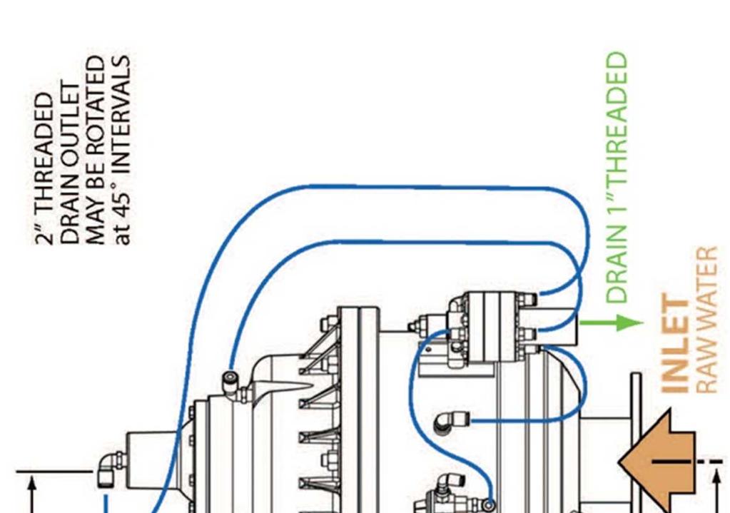
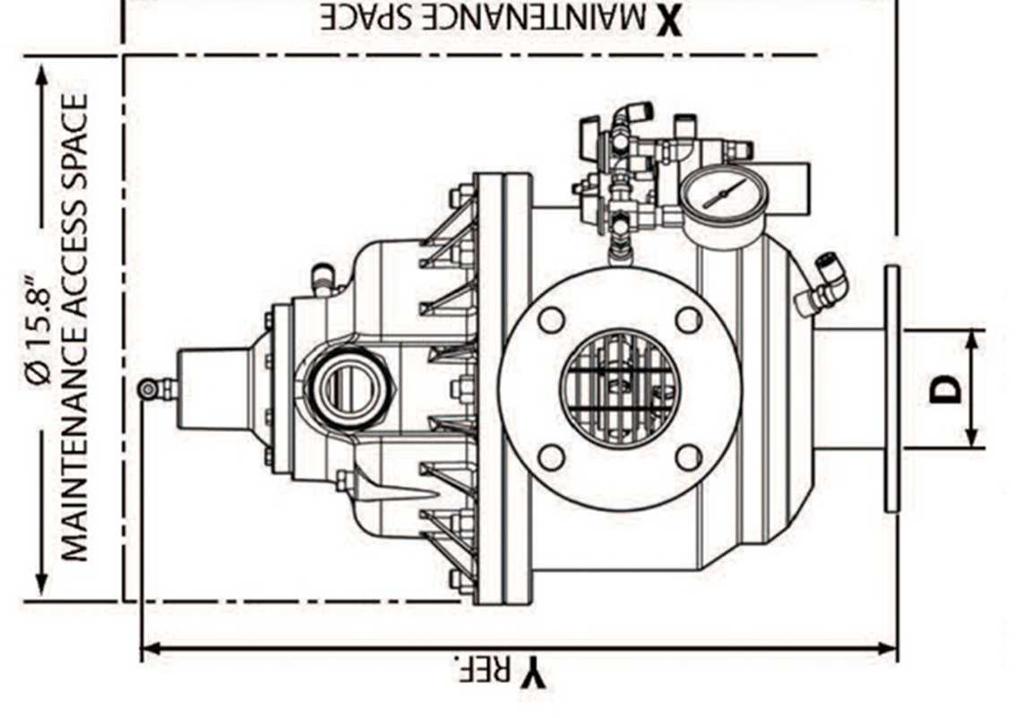
6 Dimensional Details
7 Safety Instructions Your safety and that of your co-workers and work environment is critical! We recommend that you do the following: Follow all on-site safety procedures, instructions and restrictions whilst installing, commissioning, operating and maintaining the filter. Follow all on-site requirements for safety/protective clothing such as hard hats, eye wear, hearing protection, steel caped boots, etc. If using lifting equipment ensure that it is operated by suitably qualified personnel using approved slings. Ensure that the filter can be safely accessed, isolated and maintained during and after installation. Ensure that the back flush drain line is securely fixed on installation. When the filter is pressurized do not attempt to remove any part of the filter. Ensure that any leaks are fixed immediately and that the area around the filter remains dry at all times to avoid and danger of slipping or electrocution. Do not modify or change the structure of any part of the filter. Installation Correct installation of your filter is critical to be able to get the best result from it! You will need to check and do the following: a) The filter can be installed in any orientation or position, although horizontal at waist height is preferred for servicing access. b) Fit a manual isolating valve immediately after the filter. c) Ensure that no back flow can occur through the filter, as this could damage the fine screen. d) Do not tamper or play with the Rinse Controller! This has been factory set and tested. e) Ensure that there will be enough service and access space around the filter to be able to operate, service, dismantle and maintain the filter easily in years to come. Check the drawing for your particular model. f) Ensure that you will have enough flow and pressure to backflush the filter at ALL times 30 psi). If not the line pressure will drop too low and the filter will not clean itself effectively. If you do not have enough flow/pressure available you may need to restrict the flow after the filter during the backflush cycle. g) For full flow industrial or critical installations, it is essential to install a manual by-pass around the filter. This is so that the filter can be isolated and serviced without disrupting any downstream plant or equipment. h) The backflush drain line must be at least 2 in size to prevent any back pressure on the filter. It must drain downhill. Avoid or eliminate any elbows and restrictions in the line. If the drain line is longer than 25 feet use a 3 line. i) Fit a barrel union at or near the filter on the backflush drain line so that the Cover Lid can be easily removed.
 The Rinse Control has a 1 BSP-FM drain line that will bleed water during every backflush cycle. This will need to be piped away from the filter to drain.")
8 j) Ensure that the backflush line is secured solidly and will not move or flex when high pressure water comes out of the flush valve. k) The Rinse Control has a 1 BSP-FM drain line that will bleed water during every backflush cycle. This will need to be piped away from the filter to drain. l) Fit a barrel union at the Rinse Controller 1 drain connection if you are piping this away, so that the Rinse Controller can be easily removed if required. m) If there is extensive pipe work after the filter, or if the downstream system is downhill from the filter, you may need install a hydraulic pressure sustaining valve on the downstream side of the filter. This will restrict the flow during start-up and maintain pressure at the filter until pressure builds up in the system so that the filter will not block. n) Ensure that all connections are tightened and secure. o) There will be one (1) control tube and tube fitting that will require to fitting onto the filter on installation. This # 3 line and fitting are supplied lose to avoid any damage in transport or installation. This is line # 3 from the Rinse Controller goes to the top of the Diaphragm Cover on top of the filter. Remove the fitting from the tube, fit the fitting into the cover and re-fit the 6 mm tube. The fittings are a simple Push-In type. Commissioning Before proceeding with the commissioning process double check that the inlet, outlet and drain pipe work is securely tightened and secured. a) Ensure that the small 3-Way tap for automatic/manual operation is in the AUTO position. b) Open the inlet valve (if fitted) slightly to allow water pressure into the filter and start pump if necessary. Check for leaks and fix now if any are found. c) Once the filter is pressurized, open the inlet valve fully. d) Flush the filter manually by rotating the automatic/manual 3-way tap to the OPEN position for 3 seconds then return to the AUTO position. This will cause the filter to go through a full backflush cycle. Do this at least 3 times to remove any air from the control system. (The AUTO position is pointing to the filter body as per photo). e) Whilst doing this check the line pressure on the inlet side of the filter during the backflush cycle and ensure it remains above 30 psi. f) Now slowly open the isolating valve after the filter. If you are filling empty pipelines you will need to do this
9 gradually and in stages so that the pressure stays at around the normal operating pressure of the system. Once the system is filled you will then be able to open the valve fully. g) Check the inlet and outlet pressures to make sure they are equal or near to equal, and that they stay above 30 psi at all times. h) Once the system has stabilized to its normal operating conditions with flow and pressure, manually back flush again via the 3-Way tap and check the inlet pressure again to make sure it does not drop below 30 psi at any time. i) If all appears to be in order and if possible wait for the filter to reach an automatic back flush cycle caused by a build-up of DP (differential pressure). j) Your filter should now be ready to leave online and is commissioned. Make sure the 3- way manually flushing tap is and remains in the AUTO position. Operation Once your filter has been commissioned it should operate without any external input or control. We suggest that you check the filter on a regular basis, say weekly or monthly, checking the DP and making sure the flush cycle is functioning correctly. Make sure the 3-Way tap for manual flushing is in the AUTO position. Maintenance Generally your Filtaworx filter should be trouble free, however you will need to remove the Fine Screen on a regular basis to remove any large debris from the Coarse Screen that has come into the system. The frequency of this will depend on the amount of large debris entering into the system. Grease the O Rings before reassembling the filter with suitable silicon grease. Rinse Controller The Rinse Controller is basically the brain of the filter. It is a pilot operated diaphragm valve that senses inlet and outlet pressure across a diaphragm. When the pressure drop (DP) across the filter increases it pushes a diaphragm against a spring. At about 7 psi this will actuate a backflush or cleaning cycle by opening the flush valve to drain. We recommend that you do not tamper or adjust the Rinse Controller as it has been factory set at the correct differential pressure (DP) point to keep the filter clean and functioning correctly. You should not attempt to take the Rinse Controller apart at any time. In most cases if the Controller is malfunctioning it is usually a symptom of another problem with the filter and not a problem with the controller at all. It could be either a blocked fine screen or a mechanism fault.
10 Adjusting the Rinse Control may be required if it has been tampered or played with. To do this do the following: 1) Loosen the lock nut on the adjusting screw on top of the Rinse Controller. 2) Backflush the filter manually on the 3-way tap. 3) Undo the adjusting screw anti-clockwise until the filter back flushes. 4) Turn the adjusting screw in clockwise 2 turns. 5) Tighten the lock nut back down on the adjusting screw. Disassembly Instructions Your filter can be easily disassembled by following the below instructions: a) If possible backflush the filter manually on the 3-Way tap with the downstream valve fully closed first before any work is commenced. b) Isolate / shut down and de-pressurize the filter. Make sure that the filter does not contain any residual pressure before proceeding. c) Remove the 2 x control tubes from their fittings on the Cover Lid. d) Undo and remove the Cover Lid 8 x nuts and washers holding this down. e) Remove the Cover Lid and Dirt Collector assembly from the filter. f) Drain the filter body if required so that the Fine Screen assembly is fully visible inside the filter. g) Remove the Fine Screen from the filter using the U shaped pulling tool supplied with the filter. The feet pieces of the tool fit under the 2 x stainless steel plates visible at the end of the screen. (As shown on the next page). h) The Fine Screen is seated into the housing by 2 x O Rings. If the screen has been in the housing for a long time it may be reluctant to come out, so more force may be required. i) Once the fine screen is out check it for cleanliness by holding it up to the light. You may need to clean the screen from inside to outside only! Using a high pressure water cleaner. (Karcher etc.) A garden hose or tap will not be strong enough. j) Before replacing the fine screen back into the filter, lubricate the 2 x O rings using suitable silicon grease. k) To remove the Collector Assembly, remove the 4 x Phillips head screws that attach the Partition to the Cover Lid. The Collector Assy will now pull out of the Cover Lid, (you may need to pry the Partition away from the Cover Lid) exposing the bearings and flush valve assembly.
11 Preventative Maintenance 1. Every 2 3 weeks a. Flush Filter Manually b. Check that all filter functions and cleaning cycle is operating correctly. 2. Every 3 weeks a. Clean the Mini-Filter b. Every 6 months c. Clean the coarse screen 3. Every 12 months a. Strip and inspect the complete filter internals b. Piston shaft and plunger moves in and out of the Piston freely c. The wear on the Piston Bearing and the Rotor Bearing d. The wear on the Collector Shaft and the Top Bearing e. Remove and replace any worn parts f. Check that the Fine Screen is clean Trouble Shooting Generally you will find if the filter malfunctions it will show as a high DP (differential pressure) or become blocked. This could be caused by a random condition like a sudden high dirt load event, a control malfunction or an internal mechanical fault. The trick will be to find which one of these three (3) is the cause. In most cases it is unlikely to be a Rinse Controller fault. The Rinse Controller becomes inactive if the outlet pressure drops below 50% of the inlet pressure. Problem Possible Cause Solution The valves are closed? Open valves The filter does not flush Check that the 3-way tap for manual/automatic flushing is in the AUTO Turn valve to AUTO position Pressure differential is high, >15 psi. (Rinse Controller will normally be venting water in this mode). Rinse Controller dripper blocked. (Controller venting water). Perform a manual flush cycle as follows: 1. Close the outlet valve. 2. Check that the filter inlet & outlet pressures are equal. They must be equal to be able to manually flush the unit. 3. Perform a manual flush as in Section 7.0 d, page Check the pressures at the inlet valve and in the rotor chamber. 5. If the filter has been extensively blocked then flush the filter manually 2-3 times. 6. Open the outlet valve slowly / gradually and check inlet-outlet pressures Change the dripper
12 Excessive pressure in the rotor chamber Insufficient inlet pressure (less than 30 psi) Pressure differential exceeds 70 kpa during normal operation Water does not flow through the filter Flush valve leaks or remains open Rinse Controller is not set/ adjusted correctly Control tubes or fittings to Rinse Controller are blocked or connections are incorrect Drain pipes are restricted blocked, or too long. Check and re-adjust screw on rinse controller. (Section 10) Check and clear them. Check the controller connecting diagram Check if drain lines are unrestricted and not kinked. If necessary replace with a larger diameter line, or shorten the existing line. Inlet valve is not fully open Open inlet valve fully. Increase the inlet pressure or throttle the outlet to increase pressure during the flush cycle. Fit a hydraulic pressure sustaining valve. Coarse Screen is blocked Rinse controller needs adjusting Check & clean Coarse Screen Adjust rinse controller Section 9.1 P 8 & 9 Check for blockage at pressure sensor connection 3 & 7. Flow rate is too high Check flow rate and reduce if necessary Inlet line blocked Check and clear inlet line Isolating valves are closed Open isolating valves The screen is blocked completely. Possibly causes are: Low inlet pressure, high flow, high dirt load, controller malfunction or internal mechanism problems Valve seals may be leaking or valve is jammed. Perform a manual flush as follows: 1. Close the filter outlet valve 2. Check that the filter outlet and inlet pressures are equal 3. Perform a manual flush as in Section 7.0 d, page Check the pressures at the inlet valve and in the rotor chamber. 5. If the filter has been extensively blocked then flush the filter manually 2-3 times. 6. Open the outlet valve and check inlet-outlet pressures. Remove Cover Lid and remove Collector assy. Check that it moves freely and the seals are okay, If not free the valve or replace the seals.


13 Hydraulic Control System Layout
14 Warranty Triangle Waterquip warrants all Filtaworx products against defects in material and workmanship for a period of 12 months from commissioning date or 18 months from delivery date, whichever date comes first. The warranty is limited and valid only when the product is used in accordance with the manufacturer s standards and instructions and on condition that the customer fulfills their obligations set forth in this manual. The manufacturer s liability is limited to the replacement of defective parts with new or rebuilt parts free of charge. Any freight charges are for the customer s account. This warranty is extended only to the original purchaser. A purchase receipt or other proof of date of the original purchase may be required before warranty performance is rendered. This warranty only covers failures due to defects in materials and workmanship which occur during normal use. It does not cover damage caused by accidents, misuse, abuse, neglect, mishandling, misapplication, alteration, modification or service by anyone other than the manufacturer or the manufacturers authorized agent or representative personnel. The manufacturer is not liable for incidental or consequential damage resulting from the use of this product or arising out of any breach of this warranty. All express and implied warranties including the warranties of merchantability and fitness for a particular purpose/use are limited to the applicable warranty period set forth above. In the event of a warranty claim a purchase order will be required from the customer to send the replacements part/s on. These parts will be invoiced at the standard replacement part price including freight. Faulty replaced parts are to be returned to Triangle Waterquip or their agent/distributor for evaluation, inspection and assessment, so that they can be checked for cause of damage and claim. If they are deemed to be a warranty claim then the part/s cost as invoiced will be credited to the customer, less the cost of any freight incurred. If the replacement parts are not deemed to be a warranty claim then the invoice will remain in place as is.
Installation and Operation Instruction Manual FWINSMAN303. Yardney - Filtaworx FW06EX - FW10
 Installation and Operation Instruction Manual FWINSMAN303 Yardney - Filtaworx FW06EX - FW10 Phone: 951.656.6716 Toll-Free: 800.854.4788 www.yardneyfilters.com Yardney Water Management Systems, Inc. 6666
Tekleen LPF USERS AUTOMATIC FILTERS, INC. MANUAL
 AUTOMATIC FILTERS, INC. 2672 S. LA CIENEGA BLVD. LOS ANGELES, CA 90034 310 839 2828 800 336 1942 FAX 310 839 6878 www.tekleen.com info@tekleen.com Tekleen LPF USERS MANUAL Table of Contents SECTION I INTRODUCTION
Operator's Manual. Models (¾") (1") (1½ ) (2 ) (3") (4") (6") (8")
 (1) (1½ ) (2 ) (3) (4) (6) (8)") OdisMatic Hydraulic Filter Series 851 Operator's Manual Models 85107 (¾") 85101 (1") 85115 (1½ ) 85102 (2 ) 85103 (3") 85104 (4") 85106 (6") 85108 (8") Content 1. Technical Specifications. 2. Materials.
OdisMatic Hydraulic Filter Series 851 Operator's Manual Models 85107 (¾") 85101 (1") 85115 (1½ ) 85102 (2 ) 85103 (3") 85104 (4") 85106 (6") 85108 (8") Content 1. Technical Specifications. 2. Materials.
AMIAD Automatic Filters
 AMIAD Automatic Filters Filtomat M100-6800 Series Models: M104XLP, M106XLP, M108LP, M110P Hydraulically-Controlled Serial number: Order number: Catalog number: Filtration degree: Tested by: Installation,
To ensure proper installation, digital pictures with contact information to before startup.
 Check List for Optimal Filter Performance? There should be no back-pressure on the flush line. A 1 valve should have a 2 waste line, and 2 valve should have a 3 waste line. Do not use rubber hosing or
ARKAL SCREEN LINE H - SERIES Hydraulically Operated Self-Cleaning Screen Filter SERVICE & MAINTENANCE MANUAL
 ARKAL SCREEN LINE H - SERIES Hydraulically Operated Self-Cleaning Screen Filter SERVICE & MAINTENANCE MANUAL Table of Contents Subject Page No. Introduction... 2 Safety Instructions... 3 Description &
Air Operated Double Diaphragm Pump. M-Pump ½ Metallic Non Metallic Pump INSTALLATION, OPERATION & MAINTENANCE MANUAL
 Air Operated Double Diaphragm Pump M-Pump ½ Metallic Non Metallic Pump INSTALLATION, OPERATION & MAINTENANCE MANUAL 0.5 I.O.M rev 05. 12/2015 INDEX Title Section Introduction.1 Safety.2 Warranty, General
FIXED DEPTH INSERTION METER INSTRUCTIONS
 UNPACKING Please open and inspect your package upon receipt. Your package was packed with great care and all the necessary packing materials to arrive to you undamaged. If you do find an item that is broken
MODEL 200 MULTI-JET FLOW METER
 MODEL 200 MULTI-JET FLOW METER - For Water Applications - INSTALLATION & INSTRUCTION MANUAL 8635 Washington Avenue Racine, Wisconsin 53406 Technical Toll-Free: 877.722.4631 Sales Toll-Free: 800.235.1638
MODEL 900 IMPELLER-TYPE FLOW METER
 MODEL 900 IMPELLER-TYPE FLOW METER - For Water Applications - INSTALLATION & INSTRUCTION MANUAL 8635 Washington Avenue Racine, Wisconsin 53406 Toll Free: 800.235.1638 Phone: 262.639.6770 Fax: 262.417.1155
Check List for Optimal Filter Performance
 Check List for Optimal Filter Performance There should be no back-pressure on the flush line. A 1 valve should have a 2 waste line, and a 1.5" or 2 valve should have a 3 waste line. Do not use rubber hosing
MODEL 200 MULTI-JET FLOW METER
 MODEL 200 MULTI-JET FLOW METER - For Water Applications - INSTALLATION & INSTRUCTION MANUAL 8635 Washington Avenue Racine, Wisconsin 53406 Toll Free: 800.235.1638 Phone: 262.639.6770 Fax: 262.417.1155
Colt Series C400, C500
 Colt Series C400, C500 RP/IS-A-C400/C500 C400 OSY Reduced Pressure Zone Assemblies Reduced Pressure Detector Assemblies Sizes: 2 1 2" 10" (65 250mm) Installation Service Repair Kits Maintenance For other
Maintenance Manual. Automated Fuel Maintenance System FTI-5A SINGLE TANK FUEL TECHNOLOGIES INTERNATIONAL
 Maintenance Manual Automated Fuel Maintenance System FTI-5A SINGLE TANK FUEL TECHNOLOGIES INTERNATIONAL 05/01/2016 Rev A Fuel Technologies FTI-5A Single Tank Maintenance Section FTI - Fuel Maintenance
APCO ASR-400/450 SEWAGE AIR RELEASE VALVES
 APCO ASR-400/450 SEWAGE AIR RELEASE VALVES Instruction D12005 December 2012 Instructions These instructions provide installation, operation and maintenance information for the APCO ASR- 400/450 Sewage
PENBERTHY MODELS GL AND GH GAS OPERATED JET PUMPS INSTALLATION, OPERATION AND MAINTENANCE INSTRUCTIONS
 Before installation, these instructions must be read carefully and understood. PRODUCT WARRANTY Emerson warrants its Penberthy products as designed and manufactured to be free of defects in the material
Spin Klin 3"-4" Apollo Angle
 Spin Klin 3"-4" Apollo Angle w w w. a r k a l - f i l t e r s. c o m 3"-4" Spin Klin Angle Apollo Battery Service & Maintenance Manual Table of Contents Subject Page No. 1. Introduction... 3 2. Safety
HALLMARK INDUSTRIES INC
 Performance Part No. HP. CONVERTIBLE JET PUMP USER S MANUAL GPH of Water @ Total Discharge Pressure of 40 psi Max. Pressure Max suction (shallow well) Max Suction (deep well) Max GPM (@0 head) Max Discharge
4" Spin Klin Twin Apollo Battery. Service & Maintenance Manual
 4" Spin Klin Twin Apollo Battery Service & Maintenance Manual Table of Contents Subject Page No. 1. Introduction... 3 2. Safety Instructions... 3 3. Description and Operation... 4 4. Technical Data...
Spin Klin 4" Apollo Twin
 Spin Klin 4" Apollo Twin w w w. a r k a l - f i l t e r s. c o m 4" Spin Klin Twin Apollo Battery Service & Maintenance Manual Table of Contents Subject Page No. 1. Introduction... 3 2. Safety Instructions...
Maintenance Manual. Automated. Fuel Maintenance System FTI-5A. FUEL TECHNOLOGIES INTERNATIONAL LLC
 Maintenance Manual Automated Fuel Maintenance System FTI-5A FUEL TECHNOLOGIES INTERNATIONAL LLC www.fueltechnologiesinternational.com 03/01/2011 - Fuel Technologies FTI-5A Maintenance Section FTI - Fuel
OWNER S MANUAL GUZZLER MODEL 620 READ THESE INSTRUCTIONS BEFORE USING
 OWNER S MANUAL GUZZLER MODEL 620 OPERATION MAINTENANCE TROUBLE SHOOTING REPAIR PARTS WARRANTY READ THESE INSTRUCTIONS BEFORE USING 201 COMMERCE DRIVE MONTGOMERYVILLE, PA 18936 215-393-4700 800-331-1423
QL 420 / 540 CARTRIDGE FILTER
 INSTALLATION AND OPERATING INSTRUCTIONS I INSTALLATION AND OPERATING INSTRUCTIONS NSTAL INSTALLATION AND I QL 420 / 540 CARTRIDGE FILTER 1 IMPORTANT SAFETY PRECAUTIONS ATTENTION INSTALLER: This guide contains
PENBERTHY FROST PROOF EXTENSION INSTALLATION, OPERATION AND MAINTENANCE INSTRUCTIONS
 Before installation these instructions must be read fully and understood PRODUCT WARRANTY Emerson warrants its Penberthy products as designed and manufactured to be free of defects in the material and
LAKOS AUTOMATIC SELF-CLEANING SCREEN FILTERS
 LAKOS AUTOMATIC SELF-CLEANING SCREEN FILTERS Low-maintenance, high-efficiency, high-flow screen filtration in a compact footprint APPLICATIONS Industrial Process cooling Chilled water Water treatment Flow
Model GP Triplex Ceramic Plunger Pump Operating Instructions/ Manual
 Model GP6145-3100 Triplex Ceramic Plunger Pump Operating Instructions/ Manual Contents: Installation Instructions: page 2 Pump Specifications: page 3 Exploded View: page 4 Parts List / Kits: page 5 Repair
WARNING: Do not use pumps for gasoline or highly flammable products! Do not use pumps for water based fluids, solvents or chemicals!
 50:1 Value Line Pneumatic Grease Pump Technical Brief 07/01/2010 No. 18710 201 Fits 35 lb. Pail Premium quality pneumatic pump used for 35 lb. Pail 1.Recommended Usage Grease pumps with a ratio of 50:1
COMPRESSED AIR LOADER MODEL: AL-1
 COMPRESSED AIR LOADER MODEL: AL-1 Document: AL-1 IM 10-22-2011 TABLE OF CONTENTS Important Notices and Precautions 3 Quick Installation 4 Product Description 4 Principle of Operation 5 Unpacking and Inspection
Maintenance Manual WITH ONE SUBMERSIBLE PUMP. Automated Fuel Maintenance System FTI-5A FUEL TECHNOLOGIES INTERNATIONAL LLC
 Maintenance Manual WITH ONE SUBMERSIBLE PUMP Automated Fuel Maintenance System FTI-5A FUEL TECHNOLOGIES INTERNATIONAL LLC Replacement Manuals Available on Website: www.fueltechnologiesinternational.com
PRE-PLUMBED SEWAGE SYSTEM
 PRE-PLUMBED SEWAGE SYSTEM Zoeller is a registered trademark of Zoeller Co. All Rights Reserved. MODEL #1910-0009 Español p. 13 ATTACH YOUR RECEIPT HERE Serial Number Purchase Date Questions, problems,
AMIAD Automatic Filters
 1. Model EBS AMIAD Automatic Filters Maintenance Guidelines General inspection In order to check the proper operation of the filter, close the low-pressure 1/4" valve to the pressure differential switch
MODEL 1100 TURBINE FLOW METER
 MODEL 1100 TURBINE FLOW METER INSTALLATION & INSTRUCTION MANUAL 8635 Washington Ave. Racine, Wisconsin 53406 Phone: 800.433.5263 Fax: 800.245.3569 www.hedland.com 2 OPERATIONAL START-UP Fluid entering
Steam/Water Washdown Units Safety and Operation Installation and Maintenance Instructions
 INSTALLATION AND MAINTENANCE INSTRUCTIONS IM-8-002-US October 2016 Steam/Water Washdown Units Safety and Operation Installation and Maintenance Instructions These instructions should be read by the Company
EAFM, EAFC & EAFN Filters Installation and Operating Instructions
 EAFM, EAFC & EAFN Filters Installation and Operating Instructions Please pass these instructions on to the operator of this equipment. WARNING For proper operation, the inlet water pressure must be between
Series 957, 957N, 957Z, 957RPDA, 957NRPDA, 957ZRPDA
 Series 957, 957N, 957Z, 957RPDA, 957NRPDA, 957ZRPDA Reduced Pressure Zone Assemblies Reduced Pressure Detector Assemblies Sizes: 2 1 2" 10" (65 250mm) Installation Service Repair Kits Maintenance RP/IS-957/957RPDA
MK Rittenhouse & Sons Ltd. 115 Litre/30 US Gallon Greenhouse Sprayer Manual
 MK Rittenhouse & Sons Ltd. 115 Litre/30 US Gallon Greenhouse Sprayer Manual TABLE OF CONTENTS Introduction 3 Precautions & Maintenance 4-5 Piston pump Care & Maintenance 5-6 Shut Down & Winterizing 6 Troubleshooting
JET METER INSTRUCTIONS
 UNPACKING Please open and inspect your package upon receipt. Your package was packed with great care and all the necessary packing materials to arrive to you undamaged. If you do find an item that is broken
TITAN FLOW CONTROL, INC.
 PREFACE: This manual contains information concerning the installation, operation, and maintenance of Titan Flow Control (Titan FCI) Wafer Style, Dual Plate Check Valves. To ensure efficient and safe operation
APCO CSV-1600 SURGE CHECK VALVE
 APCO CSV-1600 SURGE CHECK VALVE Instruction D12022 January 2013 Instructions These instructions provide installation, operation and maintenance information for APCO CSV-1600 Surge Check Valves. They are
DeZURIK 2 20" BOS BUTTERFLY VALVES
 2 20" BOS BUTTERFLY VALVES Instruction D10459 October 2013 2-20 BOS Butterfly Valves Instructions These instructions provide information about BOS Butterfly Valves. They are for use by personnel who are
Hydronic Corporation
 Hydronic Corporation Air Driven Hydraulic Pumps and Intensifiers P825 Installation, Use and Maintenance Manual Contents Introduction, Guarantee and Identification Plate Description, Start Up Procedures
INSTALLATION AND OPERATING MANUAL
 Publication T3-76, Rev. 1 Dated: May 9, 21 INSTALLATION AND OPERATING MANUAL MODEL: T3-I TURBOTWIN Engine Air Starter AN96-419 From Tech Development Inc 68 Poe Ave. Dayton OH 45414 Tel: (937) 898-96 Fax:
Installation and Operation Instruction Manual INSMAN-201. Industrial Multi Media Single Tank
 Installation and Operation Instruction Manual INSMAN-201 Industrial Multi Media Single Tank Phone: 951.656.6716 Toll-Free: 800.854.4788 www.yardneyfilters.com 1 Yardney Water Management Systems, Inc. 6666
CRD610 Automatic Fitting Inserter
 CRD610 Automatic Fitting Inserter OPERATIONS MANUAL VERSION 1.2 LAST EDITED 12.12.2018 cleanroomdevices.com 1 Table of Contents Title Page. 1 Table of Contents...2 1.0 General Product & Safety Information....3
APCO CRF-100A RUBBER FLAPPER SWING CHECK VALVES
 APCO CRF-100A RUBBER FLAPPER SWING CHECK VALVES Instruction D12043 June 2016 DeZURIK Instructions These instructions provide installation, operation and maintenance information for APCO CRF-100A Rubber
Pressurized Bead Filters
 Pressurized Bead Filters Installation Instructions Table of Contents Safety Information Installation Assembly Start Up Maintenance Troubleshooting Warranty Safety Information: 1. Installation should be
Installation Instructions To ensure that your installation proceeds smoothly--please read these instructions carefully before you begin.
 Single Lever Vessel Faucet Installation Instructions To ensure that your installation proceeds smoothly--please read these instructions carefully before you begin. P r o d u c t s Luxury Faucets and Accessories
GBP784B INSTALLATION TOOL
 GBP784B INSTALLATION TOOL GAGE BILT MADE IN U.S.A. GAGE BILT PRODUCTS CORP. 14500 Barber Drive (586) 771-7664 Warren, Mi 48088 (586) 771-2665 Fax e-mail:solutions@gagebilt.com / www.gagebilt.com TABLE
Maintenance Instructions for All Models
 Specifically formulated SAE 30 weight, high-grade, non-detergent pump oil with special agents for the prevention of: Scuff and wear Moisture Oxidation Foaming Rust Maintenance Instructions for All Models
STOP CITY PRESSURE BOOSTER PUMP INSTRUCTION MANUAL
 CITY PRESSURE BOOSTER PUMP INSTRUCTION MANUAL MODEL #VP05, VP10 C US NSF/ANSI 372 255405 For loose, missing or damaged parts, or if the unit does not seem to be operating properly, please call before returning
Large Hydraulic Bead Breaker
 Large Hydraulic Bead Breaker Owner s Manual WARNING: Read carefully and understand all ASSEMBLY AND OPERATION INSTRUCTIONS before operating. Failure to follow the safety rules and other basic safety precautions
Operators Manual. Model 3370 Air Cooled Recirculator rev.8/98
 Operators Manual Model 3370 Air Cooled Recirculator 110-080 rev.8/98 Table of contents Section 1. General Information 1.1 Warranty 1.2 Unpacking Section 2. Product Information 2.1 Description 2.2 Specification
INSTALLATION AND OPERATING MANUAL
 Dated: May 10, 2001 INSTALLATION AND OPERATING MANUAL MODEL: T30-Y TURBOTWIN Engine Air Starter From Tech Development Inc AN96-425 6800 Poe Ave. Dayton OH 45414 Tel: (937) 898-9600 Fax: (937) 898-8431
GL Ludemann Y-Strainers
 GL Ludemann Y-Strainers Installation, Operation and Maintenance Manual English Issue 1-03/2014 - Page 1/7 GENERAL These instructions are for installing, operation and maintenance of Y-strainers fabricated
90 SERIES SELF CLEANING WATER FILTER OPERATION & MAINTENANCE MANUAL
 90 SERIES SEF CEANING WATER FITER OPERATION & MAINTENANCE MANUA CONTENTS Filter Basics Installation Requirements Flush ine Hydraulic Connections Hydraulic Piston Filter Performance Normal Operation Backwash
CRD600 Automatic Fitting Inserter
 CRD600 Automatic Fitting Inserter OPERATIONS MANUAL VERSION 2.3 LAST EDITED 12.07.2018 cleanroomdevices.com 1 Table of Contents Title Page.. 1 Table of Contents. 2 1.0 General Product & Safety Information...3
CLEAN ROOM DEVICES, LLC "WHERE TUBING AND FITTINGS COME TOGETHER"
 CLEAN ROOM DEVICES, LLC "WHERE TUBING AND FITTINGS COME TOGETHER" CRD600 Automatic Fitting Inserter OPERATIONS MANUAL VERSION 2.1 LAST EDITED 7.25.14 DOCUMENT NUMBER 001 cleanroomdevices.com 1 Table of
Installation Manual DIAPHRAGM WELL TANK
 Installation Manual DIAPHRAGM WELL TANK IN-LINE SERIES: 2-5 & 7 GALLON VERTICAL SERIES: 14-20-25-32-36-52-65-86-96-119 GALLON HORIZONTAL SERIES: 7-14 & 20 GALLON NO LEAD NO LEAD: The weighted average of
HANDS FREE FOOT & KNEE OPERATED TAPWARE
 HANDS FREE FOOT & KNEE OPERATED TAPWARE Installation Instructions FOOT OPERATED KNEE OPERATED KNEE OPERATED TIME FLOW Self-closing Spring Action mechanism, installed on the floor and operated by pushing
ARAG Modular Manual Valve Operating Instructions and Parts Manual
 ARAG Modular Manual Valve Operating Instructions and Parts Manual Form L-1478 (11/12, Rev. C) Description California Proposition 65 Warning -- This product and related accessories contain chemicals known
RipTide. Brewing Pump. Assembly, Operation, & Maintenance
 RipTide Brewing Pump Assembly, Operation, & Maintenance Congratulations on your purchase, and thank you for selecting the RipTide brewing pump from Blichmann Engineering. We are confident that it will
1600 PSI ELECTRIC PRESSURE WASHER
 MODEL NO.: XE03 SKU: 39-8508-6 1600 PSI ELECTRIC PRESSURE WASHER Owner s Manual QUESTIONS, PROBLEMS, MISSING PARTS? Before returning to your retailer, visit our web site or call our customer service at
INSTALLATION AND OPERATING INSTRUCTIONS I INSTALLATION AND OPERATING INSTRUCTIONS. Viron P280. Viron Cartridge Filter.
 INSTALLATION AND OPERATING INSTRUCTIONS I INSTALLATION AND OPERATING INSTRUCTIONS Viron P280 Viron Cartridge Filter Pool and Spa Pump Bolero ND Cleaner INSTALLATION AND OPERATING INSTRUCTIONS Melbourne:
A Member of the. Integrated Metering Technologies
 I n s t a l l a t i o n M a n u a l A Member of the Integrated Metering Technologies 1.0 General and safety Do not install, operate or maintain this flow meter without reading, understanding and followingthe
DIRECT-DRIVE PRESSURE WASHERS
 DIRECT-DRIVE PRESSURE WASHERS PJG SERIES PRESSURE WASHER MANUFACTURED BY: PJG-2002B PJG-2502-6.5B PJG-3002B PJG-4002B INTRODUCTION Thank you for purchasing a Mancorp Pressure Washer. This manual covers
ActuLink ABS Module - ABS-MOD-400
 Installation Instructions ActuLink ABS Module - ABS-MOD-400 For more information on the installation and operation of Tuson s towable ABS system, consult the installation and operations manuals for the
SLR / SLR-S/N. Instruction Manual. Walrus America Inc
 SLR / SLR-S/N Instruction Manual Walrus America Inc 1. Installation and Connection 1.1. Pump Installation The pump should be sited in a well ventilated and frost-free position. The distance between pumps-motors
OPERATION AND PARTS MANUAL
 OPERATION AND PARTS MANUAL MODEL NUMBER : PART NUMBER : TAP- IN KIT 5100-5151 BAYNE MACHINE WORKS, INC. PHONE: (864) 288-3877 910 FORK SHOALS ROAD TOLL FREE: (800) 535-2671 GREENVILLE S.C., 29605 FAX:
B 3000 Instant Chilled Filtered Water System. User guide
 B 3000 Instant Chilled Filtered Water System User guide Thank you for choosing to install a Billi B-3000 Instant Chilled Filtered Water System. Your B-3000 is manufactured to exacting standards using high
I N S TA L L AT I O N
 I N S TA L L AT I O N k i t 9 9 5 4 Fits: all honda 750 shadow aero models Part # Included 509944 1 Skull head cover 1 Cage assembly 1 Backing plate, 3-point base 1 Dual velocity ring (not used) 1 Mounting
QUICK START GUIDE OWNER S MANUAL AL50 SERIES SAND FILTRATION TECHNOLOGY PLEASE CALL DO NOT RETURN TO STORE
 QUICK START GUIDE OWNER S MANUAL SAFETY, INSTALLATION, OPERATION & PARTS AL50 SERIES SAND FILTRATION TECHNOLOGY PLEASE CALL 877-278-2797 DO NOT RETURN TO STORE! WARNING This equipment must be installed
FPS-500. Fuel Polishing System Eliminates Microbial Contamination. Operating Manual
 FPS-500 Fuel Polishing System Eliminates Microbial Contamination Operating Manual Stabilizes Fuel Removes Water & Sludge Prevents Tank Sediments Improves Engine Reliability Optimizes Fuel Quality Optimal
GARDEN HOSE UTILITY PUMP
 GARDEN HOSE UTILITY PUMP MODEL #HPP360, HPP12V, 473707 MODEL #HPP360, 473707 MODEL #HPP12V ATTACH YOUR RECEIPT HERE Purchase Date SAFETY INFORMATION Please read and understand this entire manual before
SEWAGE PUMP MODEL # Zoeller is a registered trademark of Zoeller Co. All Rights Reserved. Español p. 14
 SEWAGE PUMP Zoeller is a registered trademark of Zoeller Co. All Rights Reserved. MODEL #1261-0001 Español p. 14 ATTACH YOUR RECEIPT HERE Serial Number Purchase Date Questions, problems, missing parts?
NYLON & PVC VALVES MINING DIVISION PRESSURE REDUCING VALVES ENSURE DOWNSTREAM PRESSURE PVC NYLON
 MINING DIVISION NYLON & PVC VALVES PRESSURE REDUCING VALVES ENSURE DOWNSTREAM PRESSURE NYLON For Gold Mines DESCRIPTION The valve maintains a preset downstream pressure, regardless of upstream pressure
Series: PFUEG 1/12HP, 5000 RPM, 60 Hz Utility Pumps
 INSTALLATION MANUAL Series: 1/12HP, 5000 RPM, 60 Hz ISP No: - 6/09 General Safety Information Before installation, read the following instructions carefully. Failure to follow instruction and Safety information
OWNERS MANUAL INSTALLATION AND OPERATING INSTRUCTIONS REPAIR PARTS LIST. Centrifugal Pump Primer MODEL 6D, HAN-DEE PRIMER
 OWNERS MANUAL INSTALLATION AND OPERATING INSTRUCTIONS REPAIR PARTS LIST Centrifugal Pump Primer 383 0893 MODEL 6D, HAN-DEE PRIMER IMPORTANT For best possible performance continuous, satisfactory operation,
SELF PRIMING CHEMICAL SERVICE PUMPS
 SELF PRIMING CHEMICAL SERVICE PUMPS INSTALLATION AND OPERATING INSTRUCTIONS This Manual covers: SELF PRIMING MODEL RANGE J50ECX TO J250ECX STAINLESS STEEL*, and NON METALLIC SEAL PUMP MODEL: SERIAL NO:
MICHIGAN FLUID POWER
 MICHIGAN FLUID POWER Air Driven Hydraulic Pumps, Power Units and Intensifiers P901 Installation, Use and Maintenance Manual Contents Introduction, Guarantee and Identification Plate Description, Start
AMB100L-im-issue INSTRUCTION MANUAL 240V DIESEL MINI BOWSER AMB100L AMB100L
 -im-issue1-2015 INSTRUCTION MANUAL 240V DIESEL MINI BOWSER INSTRUCTION MANUAL 240V DIESEL MINI BOWSER INTRODUCTION Thank you for purchasing a Macnaught 240V Diesel Mini Bowser (100 l/min) The Macnaught
Hydraulic Bead Breaker Kit
 Hydraulic Bead Breaker Kit Owner s Manual WARNING: Read carefully and understand all ASSEMBLY AND OPERATION INSTRUCTIONS before operating. Failure to follow the safety rules and other basic safety precautions
INSTALLATION AND OPERATING
 Publication T5-704, Rev. 4 Dated: November 1, 2006 INSTALLATION AND OPERATING MANUAL T50-P TURBOTWIN Engine Air Starter AN 99-448 TABLE OF CONTENTS Section Subject Page 1.0 General Information. 1 2.0 Orientation
INSTALLATION/OPERATION/MAINTENANCE INSTRUCTIONS FOR ARCHON MODELS WD2010L, WD2010, WD2010H WASHDOWN STATIONS. ARCHON Industries, Inc.
 ARCHON Industries, Inc. Washdown Stations Models WD2010L, WD2010, WD2010H Installation / Operation / Maintenance Instructions 1 This manual has been prepared as an aid and guide for personnel involved
Model BP6150. Triplex Ceramic Plunger Pump Operating Instructions/ Manual
 Model BP6150 Triplex Ceramic Plunger Pump Operating Instructions/ Manual Contents: Installation Instructions: page 2 Pump Specs: page 3 Exploded View: page 4 Parts List / Kits Torque Specifications: page
SWIMMING POOL CARTRIDGE FILTER INSTALLATION AND OPERATING INSTRUCTIONS
 SWIMMING POOL CARTRIDGE FILTER INSTALLATION AND OPERATING INSTRUCTIONS 16/03/2015 Inst336 Filtrite Cartridge Filter V06.14 2 INTRODUCTION Congratulations on the purchase of your Filtrite CF series cartridge
PPM EO-100 TM. Operation Manual
 PPM EO-100 TM Open Loop Electric Prewet Power Module Operation Manual Rev A Page 1 2/23/2010 Copyright 2008 by Cirus Controls, LLC. All Rights Reserved. No part of this material may be reproduced in any
Hydraulic Furniture Movers
 Hydraulic Furniture Movers Owner s Manual WARNING: Read carefully and understand all ASSEMBLY AND OPERATION INSTRUCTIONS before operating. Failure to follow the safety rules and other basic safety precautions
Installation Instructions
 Installation Instructions To ensure that your installation proceeds smoothly--please read these instructions carefully before you begin. P r o d u c t s Luxury Faucets and Accessories Savina Product Numbers
Cleanload Chemical Eductor
 Cleanload Chemical Eductor Operation and Parts Manual Form L-1477 (3/12, Rev. B) Description 3375P-05T4 hopper ball valve, inlet ball valve (shown) 3375P-05T4-01 hopper ball valve, no inlet ball valve
D28 SERIES WALL MOUNTED ELECTRONIC FAUCET FOR COLD OR PREMIXED WATER. D28 B D28 E D28 Dual Power B D28 Dual Power E D28 Box D28 Box E
 D28 SERIES WALL MOUNTED ELECTRONIC FAUCET FOR COLD OR PREMIXED WATER D28 B D28 E D28 Dual Power B D28 Dual Power E D28 Box D28 Box E 1 INDEX 1 TECHNICAL DATA 2-4 PACK CONTENTS 5 PRE-INSTALLATION INFO 6-11
Spin Klin 12" Super Flow
 Spin Klin 12" Super Flow w w w. a r k a l - f i l t e r s. c o m Galaxy Super Flow Spin Klin Battery Standard Automatic Backwash Operation and Maintenance Manual Filtration Process During filtration, water
16K HYDRAULIC PLANETARY CAPSTAN DRIVE
 16K HYDRAULIC PLANETARY CAPSTAN DRIVE CAUTION: READ AND UNDERSTAND THIS MANUAL BEFORE INSTALLATION AND OPERATION OF CAPSTAN DRIVE. SEE WARNINGS! TABLE OF CONTENTS FORWORD...1 WARRANTY INFORMATION...1 SPECIFICATIONS...1
AUTOMATIC SUBMERSIBLE UTILITY PUMP
 AUTOMATIC SUBMERSIBLE UTILITY PUMP Zoeller is a registered trademark of Zoeller Co. All Rights Reserved. MODEL #1043-0006 Español p. 9 ATTACH YOUR RECEIPT HERE Serial Number Purchase Date Questions, problems,
HTX-HTH SEPARATORS I&O MANUAL
 INSTALLATION OPERATIONS AND MAINTENANCE HTX-HTH SEPARATORS I&O MANUAL 1365 N. Clovis Avenue Fresno, California 93727 (559) 255-1601 www.lakos.com LS-714B (Rev. 11/17) TABLE OF CONTENTS Table of Contents...
Power Float Manifold. Installation and Operations Manual Module 11A
 Power Float Manifold Installation and Operations Manual Module 11A 2/14 Table of Contents 1 Features 3 2 Functional Purpose 3 3 4 Specifications System Installation 3 4 4.1 Hydraulic Connection 4 4.2 Electric
ProFlo FatBoy
 The Standard For Professional Grade Diaphragm Pumps. ProFlo 3300 5500 FatBoy Operational and Installation Guidelines, Repair & Parts Contents 3300 5500 Fatboy Operational and Installation Guidelines...2
Pneumatic Cylinder 14 Bore X 22 Stroke Part No. R (Formerly P )
") Pneumatic Cylinder 14 Bore X 22 Stroke Part No. R434001268 (Formerly P -193419-00003) Service Information INSTALLATION Before installing this cylinder, all air lines in the system should be blown clean
Pneumatic Cylinder 14 Bore X 22 Stroke Part No. R434001268 (Formerly P -193419-00003) Service Information INSTALLATION Before installing this cylinder, all air lines in the system should be blown clean
Installation And Operation Instruction Manual INSMAN-101. Sand Media Filters. Phone: Toll-Free:
 Installation And Operation Instruction Manual INSMAN-101 Sand Media Filters Phone: 951.656.6716 Toll-Free: 800.854.4788 www.yardneyfilters.com 1 Yardney Water Management Systems, Inc. 6666 Bo Springs Blvd.
Operating Manual High Viscosity Dispense Valve Item #
 Operating Manual High Viscosity Dispense Valve Item # 984594 CLOSE OPEN Item # 984594 Label # 8901197 Warnings INJECTION HAZARD Spray from the valve, hose leaks, or ruptured components can inject fluid
OPERATIONS MANUAL LEVER CHAIN HOIST
 OPERATIONS MANUAL LEVER CHAIN HOIST IMPORTANT SAFETY INFORMATION Please read, understand and follow all safety information contained in these instructions prior to the use of this hoist. Retain these instructions