|
|
|
- Stephany Bishop
- 5 years ago
- Views:
Transcription
1
2
3
4
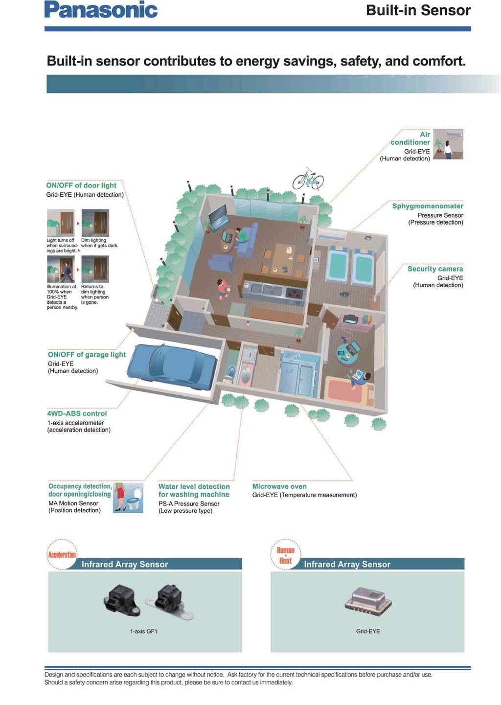
5
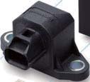
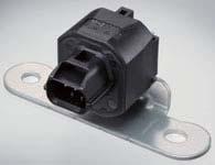
6 AGF1 Electrostatic capacitance detection sensor 1-axis acceleration sensor GF1 Direct mount Bracket Features High precision, High reliability : Superior offset voltage temperature characteristics (±33 mg (Typ.)) High sensitivity : to 3. V/g Compact size : mm inch (Direct-mount type) RoHS compliant Typical Applications Automobiles : 4WD-ABS control, neutral control, idling stop system and suspension control Special vehicles : Inclination detection (for enhanced safety and operating effi ciency) of agricultural machine, construction machine and welfare vehicles Photovoltaic generation : Sun tracking panels Ordering Information AGF 1 1 Installation type : Direct mount 1 : Bracket Number of detectable axis (Method) 1 : 1-axis accleration sensor (Electrostatic capacitance type) Detection sensitivity 3 :.136 V/(m/s 2 ) (1.333 V/g) 7 :.36 V/(m/s 2 ) (3. V/g) Operation power supply voltage 1 : 5 V.DC 2 : 12 V.DC 3 : 24 V.DC Installation direction type 1 : Horizontal type Product Types Product name 1-axis accleration sensor GF1 Operation power supply voltage 5 V.DC 12 V.DC 24 V.DC Acceleration detection range Detection sensitivity Carton : 8 pcs. (Bracket), 15 pcs. (Direct mount) Installation type Part number ±11.76 m/s 2 (±1.2 g).136 V/(m/s 2 ) (1.333 V/g) Bracket AGF11311 ±4.9 m/s 2 (±.5g).36 V/(m/s 2 ) (3. V/g) Direct mount AGF1711 ±11.76 m/s 2 (±1.2 g).136 V/(m/s 2 ) (1.333 V/g) Direct mount AGF1321 ±4.9 m/s 2 (±.5g).36 V/(m/s 2 ) (3. V/g) Direct mount AGF1721 ±11.76 m/s 2 (±1.2 g).136 V/(m/s 2 ) (1.333 V/g) Direct mount AGF1331 ±4.9 m/s 2 (±.5g).36 V/(m/s 2 ) (3. V/g) Direct mount AGF1731 Absolute Maximum Ratings Product name Unit AGF1 11 (Power supply: 5 V.DC type) Absolute maximum ratings AGF1 21 (Power supply: 12 V.DC type) AGF1 31 (Power supply: 24 V.DC type) Remarks Maximum allowable voltage V.DC Max. Ta=25 C 68 F Maximum applied AGF Max. g acceleration AGF Max. Storage temperature range C F 3 to to 185 Operation temperature range C F 3 to to 185 Anti-shock characteristic g 5, Max. Grade of protection IP67 Note : Performance when matching connector is connected. Aug. 215
7 AGF1 Electrical Characteristics AGF1 3 1 (Sensitivity : V/g type) Performance Item Unit AGF1 11 (Power supply: 5 V.DC type) AGF1 21 (Power supply: 12 V.DC type) AGF1 31 (Power supply: 24 V.DC type) Remarks Operation power supply voltage V.DC 5 V.DC±5 % 12 V.DC±1 % 24 V.DC±1 % 3 C to +85 C 22 F to +185 F Acceleration detection range 1 g ( ) ±1.2 (9) Current consumption ma 1 15 g, Ta=2 C 68 F, Max. Sensitivity V/g 1.333±3 % 3 C to +85 C 22 F to +185 F Offset voltage (g) V ±.1 Ta=2 C 68 F Offset voltage temperature characteristic V ±.93 3 C to +85 C 22 F to +185 F Other axis sensitivity % ±5 Ta=2 C 68 F Non-linearity 2 %FS ±1 Ta=2 C 68 F Frequency response Hz 1 to 15 3 db point Clamping voltage VH 3 V 4.5 Typ. Clamping voltage VL 3 V.5 Typ. AGF1 7 1 (Sensitivity : 3. V/g type) Performance Item Unit AGF1 11 (Power supply: 5 V.DC type) AGF1 21 (Power supply: 12 V.DC type) AGF1 31 (Power supply: 24 V.DC type) Remarks Operation power supply voltage V.DC 5 V.DC±5 % 12 V.DC±1 % 24 V.DC±1 % 3 C to +85 C 22 F to +185 F Acceleration detection range 1 g ( ) ±.5 (3) Current consumption ma 1 15 g, Ta=2 C 68 F, Max. Sensitivity V/g 3.±3 % 3 C to +85 C 22 F to +185 F Offset voltage (g) V ±.1 Ta=2 C 68 F Offset voltage temperature characteristic V ±.21 Note : 1 The acceleration unit g means 9.8 m/s 2. 2 Maximum error from linear output that connects +1.2 g and 1.2 g output. (AGF1 3 1) Maximum error from linear output that connects +.5 g and.5 g output. (AGF1 7 1) 3 The 12 V and 24 V.DC operating power supply voltage types can also be compatible with the clamping voltage. Please consult us. 3 C to +85 C 22 F to +185 F Other axis sensitivity % ±5 Ta=2 C 68 F Non-linearity 2 %FS ±1 Ta=2 C 68 F Frequency response Hz 1 to 15 3 db point Clamping voltage VH 3 V 4.5 Typ. Clamping voltage VL 3 V.5 Typ. Aug. 215
8 AGF1 Output voltage (V) Reference Data 1. Output characteristics AGF11311 AGF Acceleration (G) 2. Inclination angle - Output voltage characteristics Output voltage (V) AGF11311 AGF Inclination angle ( ) 3. Sensitivity temperature characteristics Sensitivity change (measured value) (%) Temperature ( C F) 4. Offset voltage temperature characteristics Offset voltage change (measured value) (mg) Temperature ( C F) 5. Frequency characteristics Gain (db) Frequency (Hz) Aug. 215
9 AGF1 Dimensions The CAD data of the products with a mark can be downloaded from: Direct mount (AGF1 1) ± ± dia dia. Detection axis GND Vout VDD Matching connector: Manufacturing company : Yazaki Corporation Housing : unit : mm inch Bracket (AGF11 1) 6.5 dia..256 dia AGF JAPAN Detection axis Part No. Lot No Matching connector : Manufacturing company : Yazaki Corporation Housing: GND VDD Vout unit : mm inch Wiring Diagram VDD VDD Vout Sensor Output GND RL RL=Load resistance (Min.5 kω) Aug. 215
10 AGF1 NOTES Before using the products, carefully check the quality under actual use conditions to enhance stability. Wire connection Correctly wire as in the connection diagram. Reverse connection may damage the product and degrade the performance. Cleaning Avoid ultrasonic cleaning as this may cause disconnection of the wire. Environment Avoid use and storage in the corrosive gas (organic solvent, sulfurous acid and hydrogen sulfide gases) which negatively affects the product. Use surge absorbers as applying the external surge voltage may damage the internal circuit. Malfunction may occur near electric noises from static electricity, lightning, broadcast or amateur radio stations and mobile phones. Avoid use in an environment where these products cause dew condensation. When water attached to the sensor chip freezes, the sensor output may be fluctuated or damaged. Do not apply high-frequency oscillation, such as ultrasonic waves, to the product. Do not use in direct sunlight or other comparable light. Other precautions These specifications are for individual components. Before use, carefully check the performance and quality under actual use conditions to enhance stability. Misconnection and the wrong range of acceleration detection may invite the risk of accidents. Avoid use beyond the specified acceleration range, as such use may damage the product. Carefully handle as static electricity may damage the product. Special notes We exert maximum efforts for quality control of the product, Please mind also about the following. 1) To prevent occurrence of unexpected circumstances, please inform us of the specifications of your product, customers, use conditions and details of the attachment position. 2) Have sufficient margin values of driving/ performance guarantee described in the specifications and apply safety measures with double circuits, if serious effects on human lives or property are predicted due to a quality failure of the product. Those countermeasures are also for the product liability. 3) A warranty period is one year after the delivery to your company. Quality assurance is limited to the items and the scopes described in the specifications. If a defect is found after the delivery, we will promptly provide a replacement or change/ repair the defect part at the place of delivery in good faith. Exceptions are below. Damages by a failure or a defect which arose after the delivery. After the delivery, when storing and transporting, if conditions other than conditions in the specifications are applied to the product. Damages by unforeseen phenomenon which cannot be predicted with the technologies available at the time of delivery. Damages by natural and anthropogenic disasters, such as earthquake, flood, fire and war, which are beyond our reasonable control. Aug. 215
11
12
13
14
15

16
17
18
19
20
21
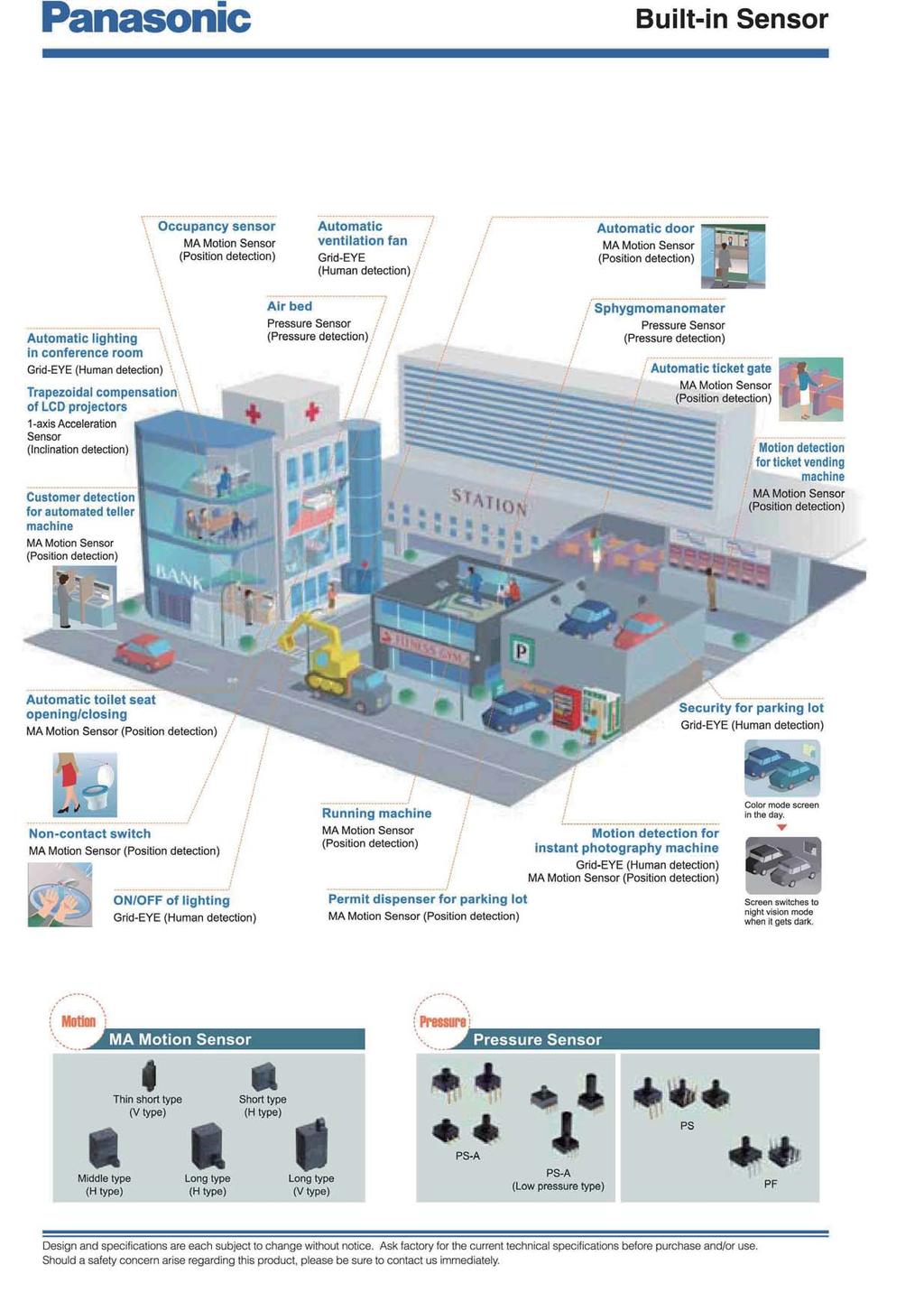
22 Infrared Array Sensor Grid-EYE (AMG88) Infrared Array Sensor Grid-EYE High Precision Infrared Array Sensor based on Advanced MEMS Technology Features Temperature detection of two-dimensional area: 8 8 (64 pixels) Digital output (capability of temperature value output) Compact SMD package (adaptively to refl ow mounting) RoHS compliant Typical applications High function home appliances (microwaves and air-conditioners) Energy saving at offi ce (air-conditioning/lighting control) Digital signage Automatic doors/elevators Ordering information AMG 8 8 Vertical pixel Horizontal pixel 8 : 8 pixels 8 : 8 pixels Applied voltage 3 : 3.3 V.DC 5 : 5. V.DC Applied voltage 3 : High performance type High gain 4 : High performance type Low gain Types Tape and reel package : 1, pcs. Product name Number of pixel Operating voltage Amplifi cation factor Part number Infrared array sensor Grid-EYE High performance type 64 (Vertical 8 Horizontal 8 Matrix) 3.3 V.DC 5. V.DC High performance type High gain High performance type Low gain High performance type High gain High performance type Low gain AMG8833 AMG8834 AMG8853 AMG8854 Rating Item Performance High gain Low gain Applied voltage 3.3 V.DC±.3 V.DC or 5. V.DC±.5 V.DC Temperature range of measuring object C to 8 C +32 F to +176 F 2 C to 1 C 4 F to +212 F Operating temperature range C to 8 C +32 F to +176 F 2 C to 8 C 4 F to +176 F Storage temperature range 2 C to 8 C 4 F to +176 F 2 C to 8 C 4 F to +176 F 2 Apr. 217
23 Infrared Array Sensor Grid-EYE (AMG88) Absolute maximum ratings Item Absolute maximum ratings Terminal Applied voltage.3 V.DC to 6.5 V.DC VDD Input voltage.3 V.DC to VDD +.3 V.DC SCL, SDA, AD_SELECT Output sink current 1 ma to 1 ma INT, SDA Static electricity (Human body model) 1 kv All terminals Static electricity (Machine model) 2 V All terminals Characteristics Performance Item High performance type High gain High performance type Low gain Temperature accuracy Typical ± C ±4.5 F Typical ±3. C ±5.4 F Human detection distance 1 7 m or less (reference value) ft NETD 2 Typ..5 C 32.9 F 1 Hz Typ..16 C F 1 Hz Viewing angle Typical 6 Optical axis gap Within Typical ±5.6 Typical 4.5 ma (normal mode) Current consumption Typical.2 ma (sleep mode) Typical.8 ma (stand-by mode) Setup time Typical 5 ms (Time to enable communication after setup) Typical 15 s (Time to stabilize output after setup) Note: 1 To have more than 4 C 7.2 F of temperature difference from background Detection object size: 7 25 mm inch (Assumable human body size) 2 It is calculated from 4 pixels of centers. Performance Item Performance Number of pixel 64 (Vertical 8 Horizontal 8 Matrix) External interface I 2 C (fast mode) Frame rate Typical 1 frames/sec or 1 frame/sec Normal Operating mode 1 Sleep Stand-by (1 sec or 6 sec intermittence) Output mode Temperature output Calculate mode No moving average or Twice moving average Temperature output resolution.25 C F Number of sensor address 2 (I 2 C slave address) Thermistor output temperature range 2 C to 8 C 4 F to +176 F Thermistor output resolution.625 C F Note: 1 Normal Mode : normal operation mode; Sleep Mode: detection is off (output and data reading not possible); Standby Mode: 1 frame measuring intermittently every 1 or 6 sec. Internal circuit 3.3 V.DC or 5 V.DC Infrared array sensor Capacitor 1 μf VDD GND 9 6 Sensor chip Selector Gain amp ADC ROM Control I 2 C I/F SDA SCL AD_SELECT INT GND Thermistor INT terminal 4 normally has same voltage as VDD. When interrupting, same as GND (V) 2 Apr. 217
24 Infrared Array Sensor Grid-EYE (AMG88) Pixel array and viewing field (1) Pixel array Pixel array from 1 to 64 is shown below. (2) Viewing field Sensor viewing field (typical) is shown below Horizontal viewing angle 6 Vertical viewing angle 6 Optical properties (1) Each pixel s viewing central angle Sensor s optical center (the origin of graph below) gap: within ±5.6 (Typical) (Both horizontal and vertical directions) (2) Each pixel s viewing angle (half angle) Central 4 pixels (Pixel No. 28, 29, 36, 37) viewing angle (half angle): horizontal direction 7.7 (Typical) vertical direction 8 (Typical) 4 Vertical viewing central angle ( ) Each pixel s horizontall viewing angle ( ) Pixel number Each pixel s vertical viewing angle ( ) Pixel number 3 4 Horizontal viewing central angle ( ) Dimensions N External dimensions P 51 Lens Part No..457 (AMG88 is omitted) Lot No Number Terminal Name 1 NC 2 SDA 3 SCL 4 INT 5 AD_SELECT 6 GND 7 NC Number Terminal Name 8 NC 9 VDD J AVDD-PC K NC L DVDD-PC M VPP N NC Note : Leave terminal NC (No.1,7,8,K and N) unconnected. Make electrical potential of terminals 9 and M the same. (.75) (.3) Recommended PC board pad 11.±.5.433± Four corners P1.27±.5 4=5.8 P.5±.2 4= N 8 P P General tolerance : ±.2 ±.8 unit : mm inch 2 Apr. 217
25 Infrared Array Sensor Grid-EYE (AMG88) External circuit (1) In case of setting I 2 C slave address of the sensor 111 Connect terminal 5 (AD_SELECT) to GND. VDD (2) In case of setting I 2 C slave address of the sensor 1111 Connect terminal 5 (AD_SELECT) to VDD. VDD 1 kω±5% 1 kω±5% 1 kω±5% 1 kω±5% 1 kω±5% 1 kω±5% 1 kω±5% To microcomputer etc. To microcomputer etc. To microcomputer etc. 2SDA 3SCL 4INT 5AD_SELECT 6GND MVPP LDVDD-PC JAVDD-PC 9VDD To microcomputer etc. To microcomputer etc. To microcomputer etc. 2SDA 3SCL 4INT 5AD_SELECT 6GND MVPP LDVDD-PC JAVDD-PC 9VDD GND 1 μf±2% 2 Ω±5% 1 μf±1% 1.5 μf±1% GND 1 μf±2% 2 Ω±5% 1 μf±1% 1.5 μf±1% This circuit is an example to drive infrared array sensor Grid-EYE, so that we will not take any responsibility of loss which is due to this circuit. Packing format (Tape and reel) Tape dimensions Dimensions of tape reel Direction of picking 12.6±.1.496±.4 16.±.3.63± ± ±.1.295±.4.69± dia dia. 2.±.1 4.±.1.79±.4.157±.4 16.±.1.63±.4.35±.5.14±.2 9.±.1 4.7±.1.354±.4.185± dia dia. Top cover tape 17.5±1..689±.39 Embossed carrier tape 13±.2 dia..512±.8 dia. 21.5±1..846±.39 8±.1 dia. 3.15±.39 dia. 38.±2. dia ±.79 dia. unit : mm inch Notes Precaution for fundamental structure of sensor Infrared Array Sensor is a thermopile type infrared sensor which detects the amount of infrared rays. Below conditions generally degrade the temperature accuracy. Carefully check the performance and stability under actual use conditions, and perform temperature corrections when necessary. When heating elements exist near the mounting position of the sensor. When the sensor is exposed to cold or hot air. When the temperature of the sensor body rapidly changes. When substances (e.g., glasses, acrylics or steams), which hardly transmit a far infrared ray, exist between the sensor and the detected object. When substances (e.g., foreign substances or water), which hardly transmit a far infrared ray, adhere to the lense of the sensor. Use environment 1) Temperature: See the specifications 2) Humidity: Between 15% and 85% R.H. (Avoid freezing and dew condensation) 3) Atmospheric pressure: Between 86 and 16 kpa 4) Vibrations and shocks may damage the sensor, and cause malfunction and performance deterioration. If loads and shocks are applied on the lense, the damaged sensor may cause malfunction and performance deterioration. 5) The product is not water/splash-proof. Perform water/dust-proofing and dew condensation/ freezing countermeasures in accordance with use environment. When dew condensation occurs, responsiveness of heat source detection may delay for several seconds. 6) Avoid use and storage in the corrosive gas (organic solvent, sulfurous acid and hydrogen sulfide gases) to avoid malfunction and performance deterioration. 7) Use surge absorbers as applying the external surge voltage may damage the internal circuit. 8) Malfunction may occur near electric noises from static electricity, lightning, broadcast or amateur radio stations and mobile phones. 9) The sensor can continuously operate within the range of using ambient temperature (using ambient humidity). However, ensure that humidity is within the range described in the following page as humidity varies according to temperature. Avoid the continuous operation near the operational limit. The temperature range does not guarantee the durability. 2 Apr. 217
26 Infrared Array Sensor Grid-EYE (AMG88) Other precautions These specifications are for individual components. Before use, carefully check the performance and quality under actual use conditions to enhance stability. 1) Once the individual sensor is dropped, do not use. Drop may cause functional disorders. 2) Writing to the unspecified register/with the unspecified bit may cause malfunction and performance deterioration. (please consult us) 3) Misconnection and use beyond the specified temperature range may damage the product. 4) Once below shocks are applied, do not use the product as applying highfrequency oscillation to the sensor body may damage the product. Contact with metal objects Contact with other sensors 5) Follow the instructions below as static electricity may damage the product. For storage and transportation, avoid plastic containers which are easily electrified. When storing and transporting the sensor, choose the environment where static electricity is hardly generated (e.g., humidity between 45 and 6 %) and protect the product by using electroconductive packaging materials. Once unpacked, perform antistatic countermeasures. (1) Operators handling sensors must wear antistatic cloths and human body grounding devices. (2) Cover the surface of workbench by electro-conductive plates and ground measuring instruments and jigs. (3) Use the soldering iron which has a small leakage current or ground the soldering tip. (4) Ground the assembling equipment. Use a stabilized power supply. A power superimposed noise may cause malfunction. Range of using ambient temperature (using ambient humidity) The sensor can continuously operate within the range of using ambient temperature (using ambient humidity). However, ensure that humidity is within the range below as humidity varies according to temperature. Avoid the continuous operation near the operational limit. Before use, check the stability under the usage environment as high humidity or high temperatures generally accelerates deterioration of the electronic component. The temperature range does not guarantee the durability High gain type 85 Tolerance range (Avoid freezing at C 32 F or below) 15 Humidity (%RH) (Avoid dew condensation) Temperature ( C, F) Low gain type 85 Tolerance range (Avoid freezing at C 32 F or below) 15 Humidity (%RH) (Avoid dew condensation at C 32 F or below) Temperature ( C, F) Mounting Use the land of the printed-circuit boardon which the sensor is securely fixed. The recommended printed-circuit board is FR4 (thickness 1.6 mm.63 inch). When mounting on the deprecated circuit board, carefully check the performance and quality under actual use conditions before use. A large noise on the power supply may cause malfunction. Place the recommended capacitor near the sensor (within 2 mm.787 inch of the wiring pattern length) between sensor input terminals (VDD-GND) to secure power superimposed noise resistance. Test with the actual machine and reselect the capacitor with optimal capacitance. Prevent the metal part of other electronic components from contacting with the sensor body as the upper face (where part numbers are imprinted) of the sensor is GND. Soldering When soldering, avoid the external thermal influence. Heat deformation may damage the sensor or deteriorate its performance. Use the non-corrosive rosin flux. 1) Manual soldering Raise the temperature of the soldering tip between 35 and 4 C 662 and 752 F (3 and 6 W) and solder within 3 seconds. The sensor output may vary if the load is applied on the terminal during soldering. Keep the soldering tip clean. 2) Reflow soldering Below are recommended temperature profiles/ conditions of reflow. When printing cream solder, the screen printing method is recommended. For the foot pattern, see the recommended diagram of the printed-circuit board. Carefully align the terminal with the pattern as self-alignment may not be reliable. The temperature of the profile is the value measured near the terminal on the printedcircuit board. After reflowing, when performing reflow soldering on the back surface of the circuit board, use an adhesive to fix the board. T3 T2 T1 t1 t2 T 1 = 15 to 18 C 32 F to 356 F T 2 = 23 C 446 F T 3 = Below 25 C 482 F t 1 = 6 to 12 sec. t 2 = Less than 3sec. 3) After soldering, do not apply stress on the soldered part when cutting or bending the circuit board. 4) Rework soldering Complete rework at a time. Use a flattened soldering tip when performing rework on the solder bridge. Do not add the flux. Keep the soldering tip below the temperature described in the specifications. 5) Prevent human hands or metal pieces from contacting with the sensor terminal. Such contact may cause anomalous outlets as the terminal is exposed to the atmosphere. 6) After soldering, prevent chemical agents from adhering to the sensor when applying coating to avoid insulation deterioration of the circuit board. 2 Apr. 217
27 Infrared Array Sensor Grid-EYE (AMG88) Wire connection 1) Correctly wire as in the connection diagram. Reverse connection may damage the product and degrade the performance. 2) Do not use idle terminals. Such use may damage the sensor. 3) For cable wiring, use shield wires with possibly short wiring lengths to prevent the influence of the noise. Cleaning Avoid ultrasonic cleaning as this may cause disconnection of the wire. Storage and transportation 1) Excessive vibrations and shocks during transport may damage the product. Carefully handle the exterior box and the reel. 2) Extremely bad storage conditions may deteriorate solderability or characteristics, and defect the appearance. Recommended conditions of the storage place are below. Temperature: to 45 C 32 to 113 F Humidity: Below 7 % R.H. Atmosphere: Low-dust and free from noxious chemicals such as sulfurous acid gas 3) The package is moisture-proof due to its sensitivity to humidity. When storing the sensor, follow the instructions below. Promptly use after opening. (within a week, below 3 C 86 F/6 % R.H.) Once unpacked, preserving in a moistureproof manner, such as keeping in a moisture-proof bag with silica gels, is recommended for long-term storage. (use within 3 months) During soldering, when adding thermal stress in a moisture absorbing state, moisture evaporates, swells and generates stress to the internal package. To avoid swellings and cracks in the surface of the package, follow the soldering conditions. 3) A warranty period is one year after the delivery to your company. Quality assurance is limited to the items and the scopes described in the specifications. If a defect is found after the delivery, we will promptly provide a replacement or change/ repair the defect part at the place of delivery in good faith. Exceptions are below. Damages by a failure or a defect which arose after the delivery. After the delivery, when storing and transporting, if conditions other than conditions in the specifications are applied to the product. Damages by unforeseen phenomenon which cannot be predicted with the technologies available at the time of delivery. Damages by natural and anthropogenic disasters, such as earthquake, flood, fire and war, which are beyond our reasonable control. Special notes We exert maximum efforts for quality control of the product, however : 1) To prevent occurrence of unexpected circumstances, please inform us of the specifications of your product, customers, use conditions and details of the attachment position. 2) Have sufficient margin values of driving/ performance guarantee described in the specifications and apply safety measures with double circuits, if serious effects on human lives or property are predicted due to a quality failure of the product. Those countermeasures are also for the product liability. 2 Apr. 217
 Digital output (capability of temperature value output) PCB mounting with connector (5pin) RoHS compliant Typical applications High function home appliances (microwaves) Energy")
28 Infrared Array Sensor Grid-EYE (AMG8854M1) Infrared Array Sensor Grid-EYE High Precision Infrared Array Sensor based on Advanced MEMS Technology Features Temperature detection of two-dimensional area: 8 8 (64 pixels) Digital output (capability of temperature value output) PCB mounting with connector (5pin) RoHS compliant Typical applications High function home appliances (microwaves) Energy saving at offi ce (lighting control) Digital signage Automatic doors/elevators Ordering information AMG M1 Vertical pixel Horizontal pixel 8 : 8 pixels 8 : 8 pixels Applied voltage 5 : 5. V.DC Gain amplification factor 4 : High performance type Low gain Type Shipment package : 1, pcs. Product name Number of pixel Operating voltage Part number Infrared array sensor Grid-EYE Narrow angle type 64 (Vertical 8 Horizontal 8 Matrix) 5. V.DC AMG8854M1 Ratings Item Performance Applied voltage 5. V.DC±.5 V.DC Temperature range of measuring object 2 C to 1 C 4 F to +212 F Operating temperature range 2 C to 1 C 4 F to +212 F Storage temperature range 2 C to 1 C 4 F to +212 F Absolute maximum ratings Item Absolute maximum ratings Terminal Applied voltage.3 V.DC to 6.5 V.DC VDD Input voltage.3 V.DC to VDD +.3 V.DC SCL, SDA, AD_SELECT Output sink current 1 ma to 1 ma INT, SDA Static electricity (Human body model) 1 kv All terminals Static electricity (Machine model) 2 V All terminals Aug. 217
29 Infrared Array Sensor Grid-EYE (AMG8854M1) Characteristics Item Performance Temperature accuracy Typical ±3. C ±5.4 F NETD 1 Max :.95 C F 1 Hz Viewing angle Typ. 35.6±3. Optical axis gap Within 4.3 Max 6. ma (normal mode at 25 C 77 F) Current consumption Max.4 ma (sleep mode at 25 C 77 F) Max 1.1 ma (stand-by mode at 25 C 77 F) Setup time Typical 5 ms (Time to enable communication after setup) Typical 15 s (Time to stabilize output after setup) Note: 1 It is calculated from 4 pixels of centers. Performance Item Performance Number of pixel 64 (Vertical 8 Horizontal 8 Matrix) External interface I 2 C (fast mode) Frame rate Typical 1 frames/sec or 1 frame/sec Normal Operating mode 1 Sleep Stand-by (1 sec or 6 sec intermittence) Output mode Temperature output Calculate mode No moving average or Twice moving average Temperature output resolution.25 C F I 2 C slave address 111 Thermistor output temperature range 2 C to 8 C 4 F to +176 F Thermistor output resolution.625 C F Note: 1 Normal Mode : normal operation mode; Sleep Mode: detection is off (output and data reading not possible); Standby Mode: 1 frame measuring intermittently every 1 or 6 sec. Internal circuit 5 V.DC Infrared array sensor Capacitor 1 μf VDD GND 9 6 Sensor chip Selector Gain amp ADC ROM Control I 2 C I/F SDA SCL AD_SELECT INT GND Thermistor INT terminal 4 normally has same voltage as VDD. When interrupting, same as GND (V) Aug. 217
30 Infrared Array Sensor Grid-EYE (AMG8854M1) Print board circuit Print board Connector SDA SCL C5 33pF 5 SDA AVDD28E C2 1.μF 4 SCL Grid-EYE (address:) DVDD18E R1 2Ω C1 1.5μF INT AD_SELECT VDD C4 68pF R2 1kΩ 3 2 VPP VDD C3 1μF GND 1 GND VPP Pixel array and viewing field (1) Pixel array Pixel array from 1 to 64 is shown below. (2) Viewing field Sensor viewing field (typical) is shown below Horizontal viewing angle 35.6 Vertical viewing angle 35.6 Optical properties (1) Each pixel s viewing central angle Sensor s optical center (the origin of graph below) gap: within ±4.3 (Both horizontal and vertical directions) (2) Each pixel s viewing angle (half angle) Central 4 pixels (Pixel No. 28, 29, 36, 37) viewing angle (half angle): horizontal direction Typ. 5. vertical direction Typ Vertical viewing central angle ( ) Each pixel s horizontall viewing angle ( ) Pixel number Each pixel s vertical viewing angle ( ) Pixel number 3 4 Horizontal viewing central angle ( ) Aug. 217
31 Infrared Array Sensor Grid-EYE (AMG8854M1) Dimensions ±.25 Part No. & Lot No ±.2 6.±.2 8.±.2 12.±.1 cl1 16. Lens 2.6 cl2 cl3 2 f2± ±.2 8.9±.2 cl ± pitch 1.5±.1 cl1 3.7 Screen printing SDA SCL VPP VDD GND Connector Maker : J.S.T connector Housing : ZHR-5 Contact : SZH-*T-P.5 7. Stamp mark area Note) cl1, cl2 is center line of the part. cl3 is center line of f2.±.5 part. General tolerance : ±.3 unit : mm Notes Precaution for fundamental structure of sensor Infrared Array Sensor is a thermopile type infrared sensor which detects the amount of infrared rays. Below conditions generally degrade the temperature accuracy. Carefully check the performance and stability under actual use conditions, and perform temperature corrections when necessary. When heating elements exist near the Setting position of the sensor. When the sensor is exposed to cold or hot air. When the temperature of the sensor body rapidly changes. When substances (e.g., glasses, acrylics or steams), which hardly transmit a far infrared ray, exist between the sensor and the detected object. When substances (e.g., foreign substances or water), which hardly transmit a far infrared ray, adhere to the lens of the sensor. Use environment 1) Temperature: See the specifications 2) Humidity: Between 15% and 85% R.H. (Avoid freezing and dew condensation) 3) Atmospheric pressure: Between 86 and 16 kpa 4) Vibrations and shocks may damage the sensor, and cause malfunction and performance deterioration. If loads and shocks are applied on the lens, the damaged sensor may cause malfunction and performance deterioration. 5) The product is not water/splash-proof. Perform water/dust-proofing and dew condensation/ freezing countermeasures in accordance with use environment. When dew condensation occurs, responsiveness of heat source detection may delay for several seconds. 6) Avoid use and storage in the corrosive gas (organic solvent, sulfurous acid and hydrogen sulfide gases) to avoid malfunction and performance deterioration. 7) Use surge absorbers as applying the external surge voltage may damage the internal circuit. 8) Malfunction may occur near electric noises from static electricity, lightning, broadcast or amateur radio stations and mobile phones. 9) The sensor can continuously operate within the range of using ambient temperature (using ambient humidity). However, ensure that humidity is within the range described in the following page as humidity varies according to temperature. Avoid the continuous operation near the operational limit. The temperature range does not guarantee the durability. Other precautions These specifications are for individual components. Before use, carefully check the performance and quality under actual use conditions to enhance stability. 1) Once the individual sensor is dropped, do not use. Drop may cause functional disorders. 2) Writing to the unspecified register/with the unspecified bit may cause malfunction and performance deterioration. (please consult us) 3) Misconnection and use beyond the specified temperature range may damage the product. 4) Once below shocks are applied, do not use the product as applying highfrequency oscillation to the sensor body may damage the product. Contact with metal objects Contact with other sensors Aug. 217
32 Infrared Array Sensor Grid-EYE (AMG8854M1) 5) Follow the instructions below as static electricity may damage the product. For storage and transportation, avoid plastic containers which are easily electrified. When storing and transporting the sensor, choose the environment where static electricity is hardly generated (e.g., humidity between 45 and 6 %) and protect the product by using electroconductive packaging materials. Once unpacked, perform antistatic countermeasures. (1) Operators handling sensors must wear antistatic cloths and human body grounding devices. (2) Cover the surface of workbench by electro-conductive plates and ground measuring instruments and jigs. (3) Ground the assembling equipment. Use a stabilized power supply. A power superimposed noise may cause malfunction. Range of using ambient temperature (using ambient humidity) The sensor can continuously operate within the range of using ambient temperature (using ambient humidity). However, ensure that humidity is within the range below as humidity varies according to temperature. Avoid the continuous operation near the operational limit. Before use, check the stability under the usage environment as high humidity or high temperatures generally accelerates deterioration of the electronic component. The temperature range does not guarantee the durability Special notes We exert maximum efforts for quality control of the product, however : 1) To prevent occurrence of unexpected circumstances, please inform us of the specifications of your product, customers, use conditions and details of the attachment position. 2) Have sufficient margin values of driving/ performance guarantee described in the specifications and apply safety measures with double circuits, if serious effects on human lives or property are predicted due to a quality failure of the product. Those countermeasures are also for the product liability. 3) A warranty period is one year after the delivery to your company. Quality assurance is limited to the items and the scopes described in the specifications. If a defect is found after the delivery, we will promptly provide a replacement or change/ repair the defect part at the place of delivery in good faith. Exceptions are below. Damages by a failure or a defect which arose after the delivery. After the delivery, when storing and transporting, if conditions other than conditions in the specifications are applied to the product. Damages by unforeseen phenomenon which cannot be predicted with the technologies available at the time of delivery. Damages by natural and anthropogenic disasters, such as earthquake, flood, fire and war, which are beyond our reasonable control. Storage and transportation 1) Excessive vibrations and shocks during transport may damage the product. Carefully handle the exterior box. 2) Extremely bad storage conditions may characteristics, and defect the appearance. Recommended conditions of the storage place are below. Temperature: to 45 C 32 to 113 F Humidity: Below 7 % R.H. Atmosphere: Low-dust and free from noxious chemicals such as sulfurous acid gas Humidity (%RH) 85 Tolerance range (Avoid freezing at C 32 F or below) 15 (Avoid dew condensation at C 32 F or below) Temperature ( C, F) Aug. 217
33 Pressure Sensor/PS-A (ADP5) Pressure Sensor PS-A Pressure sensor Built-in amplifi er and compensating circuit Features Built-in amplifier and temperature compensation circuit, no need for circuit design and characteristic adjustment High accuracy and reliability : overall accuracy ±1.25% FS (Standard), ±% FS (Low-pressure type) Compact size, space-saving : compatible size for PS type (Standard/Economy, S and M packages) RoHS compliant Typical Applications Industrial use : pressure switches and pneumatic components, compressed air pressure measuring devices Medical use : blood pressure meters, oxygen generator and airbeds Others : pressure sensing devices for air pressure mediums Low-pressure type Water level detection for domestic appliances: washing machines and dishwashers Air pressure control : cleanrooms and smoking rooms Medical applications : breathing pressure measuring devices Ordering Information ADP5 Terminal profile 1 : DIP terminal 2 : SMD terminal Rated pressure 1 : ±1 kpa : 1 kpa : : : : : 25 kpa 5 kpa 1 kpa 2 kpa 5 kpa 7 : 1, kpa A : 4 kpa B6: 6 kpa Package/Pressure inlet hole : S Package length : 3 mm.118 inch, diameter : 3 mm.118 inch 1 : M Package length : 5 mm.197 inch, diameter : 3 mm.118 inch 2 : L Package (Only low pressure type) length : 13.5 mm.531 inch, diameter : 5.45 mm.215 inch 3 : P Package (Only low pressure type) length : 15.6 mm.615 inch, diameter : 5.45 mm.215 inch (Low pressure type) Base type Nil: With glass base (Standard type) Low pressure type 1 : Without glass base (Economy type) Note : Some part numbers may not be available depending on the combination. Please refer to the Table of PRODUCT TYPES on the next page. Product Types Pressure Package (Pressure inlet hole length) Terminal Part No. Standard type Standard/Economy type Low pressure type S Package M Package M Package L Package P Package (3 mm.118 inch) (5 mm.118 inch) (5 mm.197 inch) (13.5 mm.531 inch) (15.6 mm.614 inch) DIP terminal SMD terminal DIP terminal SMD terminal DIP terminal DIP terminal DIP terminal ±1 kpa ADP51 ADP52 ADP511 ADP521 1 kpa ADP511 ADP521 ADP5111 ADP5211 Standard 25 kpa ADP512 ADP5121 type 5 kpa ADP513 ADP5131 (with glass 1 kpa ADP514 ADP524 ADP5141 ADP5241 base) 2 kpa ADP515 ADP525 ADP5151 ADP kpa ADP516 ADP526 ADP5161 ADP5261 1, kpa ADP517 ADP527 ADP5171 ADP5271 Economy type (without glass base) 4 kpa ADP51A11 Low pressure type 6 kpa ADP51B61 ADP51B62 ADP51B63 Standard packing : Carton : 1 pcs.; Case : 1, pcs. Aug. 215
34 Pressure Sensor/PS-A (ADP5) Rating Standard type Item Standard type (with glass base) Remarks Type of pressure Gauge pressure Pressure medium Air 1 Rated pressure (kpa) ± , 1.5 times Max. applied pressure Twice of the rated pressure the rated pressure Ambient temperature 1 C to +6 C 14 F to +14 F (no freezing or condensation) Storage temperature 2 C to +85 C 4 F to +185 F (no freezing or condensation) Drive voltage 5±.25 V.DC Temperature compensation range C to 5 C 32 F to 122 F Offset voltage ±.5.5±.5 V 2, 3, 5 Rated output voltage 4.5±.5 (+when 4.5±.5 V 2, 3, 5 +1kPa) Overall accuracy ±1.25 %FS 3, 4, 5 Current consumption Max. 1 ma 2, 3 Output impedance 15 Ω (Typical) 2 Source current Max..2 ma 2, 3 Sink current Max. 2 ma 2, 3 Notes : 1 Please consult us for pressure media other than air. 2 Indicates output when temperature is 25 C 77 F. 3 Indicates output when drive voltage is 5 V. Although output fl uctuates due to fl uctuations in the drive voltage, this is not included. 4 Overall accuracy indicates the accuracy of the offset voltage and rated output voltage at a temperature compensation range of to 5 C 32 to 122 F. 5 Accuracy is the value at the time of our shipping. Please set Zero-point calibration function on your products in order to safely use if the offset voltage is shifted. Economy type Item Economy type (without glass base) Remarks Type of pressure Gauge pressure Pressure medium Air 1 Rated pressure (kpa) 4 Max. applied pressure Twice of the rated pressure Ambient temperature 5 C to +5 C 23 F to +122 F (no freezing or condensation) Storage temperature 2 C to +7 C 4 F to +158 F (no freezing or condensation) Drive voltage 3±.15 V.DC Temperature compensation range 5 C to 45 C 41 F to 113 F Offset voltage.3±.9 V 2, 3, 5 Span voltage 2.4±.3 V 2, 3, 5 Offset voltage temperature characteristics ±4. %FS 3, 4, 5 Sensitivity temperature characteristics 1.3 %FS 3, 4, 5 Current consumption Max. 3 ma 2 Output impedance 2 Ω (Typical) 2, 3 Source current Max..15 ma 2, 3 Sink current Max. 1.5 ma 2, 3 Notes : 1 Please consult us for pressure media other than air. 2 Indicates output when temperature is 25 C 77 F. 3 Indicates output when drive voltage is 3 V. Although output fl uctuates due to fl uctuations in the drive voltage, this is not included. 4 Indicates from output value at 25 C 77 F and the change of output at 5 and 45 C 41 to 113 F. 5 Accuracy is the value at the time of our shipping. Please set Zero-point calibration function on your products in order to safely use if the offset voltage is shifted. Aug. 215
35 Pressure Sensor/PS-A (ADP5) Low pressure type Item Economy type (without glass base) Remarks Type of pressure Gauge pressure Pressure medium Air 1 Rated pressure (kpa) 6 Max. applied pressure Twice of the rated pressure Ambient temperature C to +7 C 32 F to +158 F (no freezing or condensation) Storage temperature 3 C to +1 C 22 F to +212 F (no freezing or condensation) Drive voltage 5±.25 V.DC Temperature compensation range C to 7 C 32 F to 158 F Offset voltage.5 V (Typical) 2 Span voltage 4. V (Typical) 2 Overall accuracy ± %FS 2, 3, 4 Current consumption Max. 1 ma Output impedance 5 Ω (Typical) Source current Max..2 ma Sink current Max. 2. ma Notes : 1 Please consult us for pressure media other than air. 2 Indicates output when drive voltage is 5 V. Although output fl uctuates due to fl uctuations in the drive voltage, this is not included. 3 Overall accuracy indicates the accuracy of the offset voltage and span voltage at temperatures between to 7 C 32 to 158 F (FS=4V) 4 The initial offset voltage error is not included in the overall accuracy. Reference Data Standard type 1.-(1) Output voltage ADP517 Drive voltage : 5 V.DC Temperature : 25 C 77 F Applied pressure : to +1, kpa Output voltage (V) Output voltage (V) Pressure (kpa) Pressure (kpa) 1 2.-(1) Output voltage ADP51 Drive voltage : 5 V.DC Temperature : 25 C 77 F Applied pressure : 1 to +1 kpa 1 Accuracy (%FS) Accuracy (%FS) 1.-(2) Overall accuracy (Offset voltage) ADP517 Drive voltage : 5 V.DC Temperature : to 5 C 32 to 122 F Applied pressure : kpa Temperature ( C F) 2.-(2) Overall accuracy (Offset voltage) ADP51 Drive voltage : 5 V.DC Temperature : to 5 C 32 to 122 F Applied pressure : kpa Temperature ( C F) Accuracy (%FS) Accuracy (%FS) Temperature ( C F) (3) Overall accuracy (Rated output voltage) ADP517 Drive voltage : 5 V.DC Temperature : to 5 C 32 to 122 F Applied pressure : +1, kpa 2.-(3) Overall accuracy (Rated output voltage) ADP51 Drive voltage : 5 V.DC Temperature : to 5 C 32 to 122 F Applied pressure : +1 kpa Temperature ( C F) Aug. 215
36 Pressure Sensor/PS-A (ADP5) Low pressure type 1 Output voltage ADP51B61 Drive voltage : 5 V.DC Temperature : 25 C 77 F Applied pressure : to 6 kpa 2 THB (high temperature high humidity bias test) ADP51B61 Within 85 C 185 F and 85% RH 5 V applied between No.2 (Vdd) and No.3 (GND) Applied pressure : kpa Output voltage (V) Offset voltage (V) Span voltage (V) Applied pressure (kpa). intial 1h 5h 3.5 intial 1h 5h 3 Ambient temperature characteristics Ambient temperature : 25 C 77 F C 32 F 1 C 5 F 6 C 14 F 7 C 158 F Offset voltage (V) Temperature ( C F) Span voltage (V) Temperature ( C F) 4 Shock test ADP51B61 Shock applied : 981 m/s 2, 3 times in x, y and z directions Applied pressure : kpa Offset voltage (V) Span voltage (V) intial after test 3.5 intial after test 5 Vibration test ADP51B61 Vibration applied : 1 to 55 Hz, amplitude : 1.5mm, x, y and z directions, 2 hrs each Applied pressure : kpa Offset voltage (V) Span voltage (V) intial after test 3.5 intial after test Aug. 215
37 Pressure Sensor/PS-A (ADP5) 6 Temperature/humidity cycle test ADP51B61 Exposed to 1 cycles in the temperature and humidity conditions given below. Applied pressure : kpa Temp. 65 C 149 F 25 C 77 F Time 95% RH 1 cycle (24h) 65 C 149 F 1 C 14 F % RH 25 C 77 F h 3h h h 3h h 1.5h 3.5h 3h Offset voltage (V) intial 1 cyc Span voltage (V) intial 1 cyc Evaluation Test Classifi cation Tested item Tested condition Result Storage at high temperature Temperature : Left in a 85 C 185 F constant temperature bath; Time : 1 hrs. Passed Environmental Storage at low temperature Temperature : Left in a 2 C 4 F constant temperature bath; Time : 1 hrs. Passed characteristics Humidity resistance Temperature/humidity : Left at 4 C 14 F, 9 % RH; Time : 1 hrs. Passed Temperature cycle Temperature : 2 C to 85 C 4 F to 185 F; 1 cycle : 3 min.; Times of cycle : 1 Passed Endurance characteristics Mechanical characteristics Soldering Characteristics High temperature/ high humidity operation Temperature/humidity : 4 C 14 F, 9% RH; Operation times : 1 6, rated voltage applied Passed Vibration resistance Double amplitude : 1.5 mm.59 inch; Vibration : 1 to 55 Hz; Applied vibration direction : X, Y, Z 3 directions; Times : 2 hrs each Passed Dropping resistance Dropping height : 75 cm inch; Times : 2 times Passed Terminal strength Pulling strength : 9.8 N {1 kgf}, 1 sec.; Bending strength : 4.9 N {.5 kgf}, left and right 9 1 time Passed Solderbility Temperature : 23 C 446 F; Time : 5 sec. Passed Heat resistance (DIP) Temperature : 26 C 5 F; Time : 1 sec. Passed Items Offset voltage Rated Output Voltage Criteria Variation amount within ±%FS of value Aug. 215
38 Pressure Sensor/PS-A (ADP5) Dimensions The CAD data of the products with a mark can be downloaded from: Standard type S Package (Terminal direction : DIP terminal Pressure inlet hole length : 3 mm.118 inch) ADP51 Pressure inlet hole f2.2 f.87 Vcc NU Vout 7.Max..276Max. 7.2Max..283Max. Recommended PC board pattern 6-f.9 6-f.35 Terminal connection diagram 123 Vcc DC 5V Vout GND NU NU 4-R.7 4-R C f3. f.118 R.2 R GND Atmospheric pressure inlet hole GND NU NU JAPAN Vcc NU Vout unit : mm inch General tolerance : ±.3 ±.12 Terminal No. Name 1 Vcc (Power supply [+]) 2 NU (Not usable) 3 Vout (Output) 4 NU (Not usable) 5 NU (Not usable) 6 GND (Ground) Standard type S Package (Terminal direction : SMD terminal Pressure inlet hole length : 3 mm.118 inch) ADP52 Pressure inlet hole f2.2 f.87 Vcc NU Vout 7.Max..276Max. 7.2Max..283Max. Recommended PC board pattern Terminal connection diagram 123 Vcc DC 5V Vout GND NU NU 4-R.7 4-R C f3. f.118 R.2 R GND Atmospheric pressure inlet hole.98 GND NU NU JAPAN Vcc NUVout unit : mm inch General tolerance : ±.3 ±.12 Terminal No. Name 1 Vcc (Power supply [+]) 2 NU (Not usable) 3 Vout (Output) 4 NU (Not usable) 5 NU (Not usable) 6 GND (Ground) Aug. 215
39 Pressure Sensor/PS-A (ADP5) Dimensions The CAD data of the products with a mark can be downloaded from: Standard/Economy type M Package (Terminal direction : DIP terminal Pressure inlet hole length : 5 mm.197 inch) ADP51 1/ADP51A11 Pressure inlet hole f2.2 f.87 Vcc NU Vout 7.Max..276Max. 7.2Max..283Max. Recommended PC board pattern 6-f.9 6-f.35 Terminal connection diagram 123 Vcc DC 5V Vout GND NU NU f3. f R.7 4-R.28 R.2 R C GND Atmospheric pressure inlet hole GND NU NU JAPAN Vcc NU Vout unit : mm inch General tolerance : ±.3 ±.12 Terminal No. Name 1 Vcc (Power supply [+]) 2 NU (Not usable) 3 Vout (Output) 4 NU (Not usable) 5 NU (Not usable) 6 GND (Ground) Standard type M Package (Terminal direction : SMD terminal Pressure inlet hole length : 5 mm.197 inch) ADP52 1 Pressure inlet hole f2.2 f.87 Vcc NC Vout 7.Max..276Max. 7.2Max..283Max. Recommended PC board pattern Terminal connection diagram 123 Vcc DC 5V Vout GNDNC NC f3. f R.7 4-R.28 R.2 R C GND unit : mm inch General tolerance : ±.3 ±.12 Atmospheric pressure inlet hole GND NC NC JAPAN Vcc NC Vout Terminal No. Name 1 Vcc (Power supply [+]) 2 NU (Not usable) 3 Vout (Output) 4 NU (Not usable) 5 NU (Not usable) 6 GND (Ground) Aug. 215
40 Pressure Sensor/PS-A (ADP5) Dimensions The CAD data of the products with a mark can be downloaded from: Low pressure type M Package (Terminal direction : DIP terminal, Pressure inlet hole length : 5 mm.197 inch) ADP51B61 Pressure inlet hole P4 3=7.62 P.1 3= Recommended PC board pattern (BOTTOM VIEW) Terminal connection diagram P4 3=7.62 P.1 3= P/N,Lot B JAPAN Atmospheric pressure inlet hole R.5 R NU VccGndVout NU NU NU NU f3. f f1.2 8-f Terminal No. Name 1 NU (Not usable) 2 Vcc (Power supply [+]) 3 GND (Ground) 4 Vout (Output) μf 1. μf unit : mm inch General tolerance : ±.3 ±.12 Terminal No. Name 5 NU (Not usable) 6 NU (Not usable) 7 NU (Not usable) 8 NU (Not usable) Low pressure type L Package (Terminal direction : DIP terminal, Pressure inlet hole length : 13.5 mm.531 inch) ADP51B62 Pressure inlet hole P4 3=7.62 P.1 3= Recommended PC board pattern (BOTTOM VIEW) Terminal connection diagram P4 3=7.62 P.1 3= R.5 R f5.45 f f1.2 8-f P/N,Lot B JAPAN C.3 C.12 Atmospheric pressure inlet hole NU VccGndVout NU NU NU NU Terminal No. Name 1 NU (Not usable) 2 Vcc (Power supply [+]) 3 GND (Ground) 4 Vout (Output) Low pressure type P Package (Terminal direction : DIP terminal, Pressure inlet hole length : 15.6 mm.614 inch) ADP51B63.1 μf 1. μf unit : mm inch General tolerance : ±.3 ±.12 Terminal No. Name 5 NU (Not usable) 6 NU (Not usable) 7 NU (Not usable) 8 NU (Not usable) Pressure inlet hole Atmospheric pressure inlet hole P4 3=7.62 P.1 3= Recommended PC board pattern (BOTTOM VIEW) P4 3=7.62 P.1 3=.3 Terminal connection diagram f5.45 f f1.2 8-f P/N, Lot B JAPAN f3. f NUVccGndVout NUNU NUNU 4.1 Terminal No. Name 1 NU (Not usable) 2 Vcc (Power supply [+]) 3 GND (Ground) 4 Vout (Output).1 μf 1. μf unit : mm inch General tolerance : ±.3 ±.12 Terminal No. Name 5 NU (Not usable) 6 NU (Not usable) 7 NU (Not usable) 8 NU (Not usable) Aug. 215
 AGF1 Electrostatic capacitance detection sensor 1-axis acceleration sensor GF1 Direct mount Bracket Features High precision, High reliability : Superior offset voltage temperature characteristics (±33
Pressure Sensor/PS-A (ADP5)
") Sensor PS-A sensor Built-in amplifi er and compensating circuit Features Built-in amplifier and temperature compensation circuit, no need for circuit design and characteristic adjustment High accuracy
Sensor PS-A sensor Built-in amplifi er and compensating circuit Features Built-in amplifier and temperature compensation circuit, no need for circuit design and characteristic adjustment High accuracy
Pressure sensor with built-in amplification and temperature compensation circuit
 sensor with built-in amplification and temperature compensation circuit PS-A PRESSURE SENSOR (built-in amplification and temperature compensating circuit) NEW FEATURES 1. Contains built-in amplification
PS-A PRESSURE SENSOR PS-A (ADP5) (built-in amplification and temperature compensating circuit)
 (built-in amplification and temperature compensating circuit)") PS-A (ADP) New RoHS Directive compatibility information http://www.mew.co.jp/ac/e/environment/ FEATURES. Contains built-in amplification and temperature compensation circuit. Circuit design
PS-A (ADP) New RoHS Directive compatibility information http://www.mew.co.jp/ac/e/environment/ FEATURES. Contains built-in amplification and temperature compensation circuit. Circuit design
MEMS Gauge Pressure Sensor
 MEMS Gauge Pressure Sensor MEMS Gauge Pressure Senser Featuring Small Size and Low Power Consumption Ultra-miniature 6.1 4.7 8.2 mm (L W H). Superior electrical characteristics to capative type pressure
Ordering Information. MEMS Gauge Pressure Sensor 2SMPP. MEMS Gauge Pressure Sensor Featuring Small Size and Low Power Consumption
 MEMS Gauge Pressure Sensor 2SMPP MEMS Gauge Pressure Sensor Featuring Small Size and Low Power Consumption Ultra-miniature 6.1 4.7 8.2 mm (L W H). Piezo Resistive element provides electrical characteristics
Applications. Car audio. Robo
 Rotary Position Sensor High Rotational Life Type Features High Durability: 1M cycles Pb Free Soldering: 260 C Operating Temperature: -40 C to +85 C Terminal Shape: SMD Type and Lead Type Rotational Rotor:
DC-DC Converter DATA Sheet
 DC-DC Converter DATA Sheet MYSDM3R306EENL 1 1. Features Dual Output Voltage High efficiency, smll size and low profile. Surface Mount Type of Nom-insulated DC-DC Converter Fast Transient Response (Vout2)
TL RELAYS. TYPICAL APPLICATIONS Head lamp, Fog lamp, Fan motor, etc. ORDERING INFORMATION TYPES. High Load Relay for Smart Junction Box ACTL.
 High Load Relay for Smart Junction Box TL RELAYS High heat-resistant type: Sealed Pin in Paste compliant type: Flux tight New 14.4.7 11.433 1.3 FEATURES Large capacity switching
Rotary Position Sensors
 RE.pdf Rotary Position Sensors SMD/Lead Dust-proof Type 12mm Size SV01 Series Features 1. Dust-proof construction protects the interior from dust, which maintains stable characteristics. 2. Compliant to
MEMS Air Velocity Sensor D6F-W. Application Examples. Ordering Information
 MEMS Air Velocity Sensor Compact, intelligent sensors featuring MEMS precision technology for repeatable airflow detection. Precision uni-directional air velocity detection. Integral passive Dust Segregation
3. Block Diagram Pin Number, Function Pin No. Symbol Function 4. Environmental Conditions 1 Vin1 Ch1 Voltage Input Terminal 2,3 Vin23 Ch2,3 Voltage In
 DC-DC Converter DATA Sheet MYSTM0051EEEFA 1. Features Triple Output Voltage High efficiency, smll size and low profile. Surface Mount Type of Nom-insulated DC-DC Converter Fast Transient Response (Vout2
COMPACT FLAT SIZE FOR AUTOMOTIVE
 PACT FLAT SIZE FOR AUTOMOTIVE RELAYS RoHS compliant FEATURES Compact flat type Flat size enables it to be built-in switch units. PC board terminal type: 9.5 mm.374 inch Surface-mount terminal
COMPACT FLAT SIZE FOR AUTOMOTIVE
 PACT FLAT SIZE FOR AUTOMOTIVE RELAYS RoHS compliant FEATURES Compact flat type Flat size enables it to be built-in switch units. PC board terminal type: 9.5 mm.374 inch Surface-mount terminal
Ratings 0402 inch size : Type ERBRD ERBRD R X 0R25 0R3 0R37 0R50 0R75 R00 R25 R50 2R00 2R50 3R00 Rated Current (A)
") Micro Chip Fuse Type: ERBRD Features Small size Fast-acting and withstanding in-rush current characteristics RoHS compliant Approved Safety Standards UL248-4 : File No.E94052 c-ul C22.2 No.248-4 : File
Micro Chip Fuse Type: ERBRD Features Small size Fast-acting and withstanding in-rush current characteristics RoHS compliant Approved Safety Standards UL248-4 : File No.E94052 c-ul C22.2 No.248-4 : File
Small Type High-Speed Response POL DC-DC Converter BSV-nano Series
 is a small (xxmm), light, 4A output step-down DC-DC converter with low output voltage from 08V and an accuracy of ±% typ It can support the latest DSP, ASIC applications High efficiency and high-speed
MYPMA01218RCF-CAB Non-isolated type
 FEATURES 120W DC-DC converter(216w peak) Output Voltage:12V Low ripple and Low surge output. Input Voltage:36V-75V Working Temperature -20 - +85 High Efficiency up to 95% Compact Size 86.5x122.4x35.4mm
Technical Information Solid State Relays. Glossary. Solid State Relays
 Glossary Terms Meaning Circuit functions Photocoupler Transfers the input signal and insulates inputs and outputs as well. Photoctriac coupler Zero cross circuit Trigger circuit Snubber circuit A circuit
Pressure Drop (Reference (typical)) 0.19 kpa 0.48 kpa Operating Temperature
) 0.19 kpa 0.48 kpa Operating Temperature") MEMS Mass Flow Sensor D6F-P A Compact, High-performance Flow Sensor with Dust Segregation Structure. Built in Dust Segregation System (DSS) with cyclone flow structure, diverts particulates from sensor
MEMS Mass Flow Sensor D6F-P A Compact, High-performance Flow Sensor with Dust Segregation Structure. Built in Dust Segregation System (DSS) with cyclone flow structure, diverts particulates from sensor
TURQUOISE STROKE SWITCHES
 Long Stroke and Sliding Contact Construction Sealed Switches TURQUOISE STROKE SWITCHES 13.3 10.1 (Unit: ) RoHS compliant FEATURES For pin plunger type, it maintains a long stroke OT (Over Travel) with
DC-DC Converter DATA Sheet
 DC-DC Converter DATA Sheet MYSDM3R306EENL MYSDM3R306EENL DATA Sheet 1 1. Features Dual Output Voltage High efficiency, smll size and low profile. Surface Mount Type of Nom-insulated DC-DC Converter Fast
COMPACT BUT CUT OFF DC POWER CURRENT, POWER CAPSULE CONTACT RELAY
 COMPACT BUT CUT OFF DC POWER CURRENT, POWER CAPSULE CONTACT RELAY EB RELAYS (AEB) (1A type) FEATURES Compact and high capacity using double contacts in series and permanent magnet installed. (1,A/3 times)
Reference Only. Inductance Frequency (μh) Tolerance Typ Max (MHz min.) 85 *
 Tolerance Typ Max (MHz min.) 85 *") P.1/10 CHIP COIL (CHIP INDUCTORS) LQM2HPN G0L REFERENCE SPECIFICATION 1. Scope This reference specification applies to LQM2HPN_G0 series, Chip Coil (Chip Inductors). 2. Part Numbering (ex) LQ M 2H P N
P.1/10 CHIP COIL (CHIP INDUCTORS) LQM2HPN G0L REFERENCE SPECIFICATION 1. Scope This reference specification applies to LQM2HPN_G0 series, Chip Coil (Chip Inductors). 2. Part Numbering (ex) LQ M 2H P N
G6K. Surface Mounting Relay with the World s Smallest Mounting Area. Application Examples. Model Number Legend. Ordering Information
 with the World s Smallest Mounting Area Subminiature model as small as.2 (H). (W) (L) mm is ideal for high-density mounting ((U)-2F(-Y)). Low profile of.2 mm improves mounting efficiency ((U)-2F(-Y)).
Reference Only. 1. Scope This reference specification applies to LQM2MPN_G0L series, Chip Coil (Chip Inductors).
.") Spec No. JELF243B-22L-1 P1/9 CHIP COIL (CHIP INDUCTORS) LQM2MPN GL REFERENCE SPECIFICATION 1. Scope This reference specification applies to LQM2MPN_GL series, Chip Coil (Chip Inductors). 2. Part Numbering
Spec No. JELF243B-22L-1 P1/9 CHIP COIL (CHIP INDUCTORS) LQM2MPN GL REFERENCE SPECIFICATION 1. Scope This reference specification applies to LQM2MPN_GL series, Chip Coil (Chip Inductors). 2. Part Numbering
ITVX Series. Stepless control of air pressure proportional to an electrical signal. Supply pressure: 5.0 MPa
 5.0 MPa Maximum Supply Pressure High Pressure Electro-Pneumatic Regulator X Series This product is only for blowing gas. This product does not have sufficient pressure control for other applications (driving,
Reference Only. *B: Bulk packing also available. Inductance. Tolerance M:±20% N:±30% 0.150±25% 1.0 * * N:±30% 0.23±25% 0.8 *2 0.
 CHIP COIL (CHIP INDUCTORS) LQM21PN GRD REFERENCE SPECIFICATION P.1/9 1. Scope This reference specification applies to LQM21PN_GR series, Chip Coil (Chip Inductors). 2. Part Numbering (ex) LQ M 21 P N 1R
Notice for TAIYO YUDEN products
 Notice for TAIYO YUDEN products Please read this notice before using the TAIYO YUDEN products. REMINDERS Product information in this catalog is as of October 2014. All of the contents specified herein
Tactile Switch. Ordering Information. A Wide Range of Models: 6 x 6 mm, 12 x 12 mm, Vertical, and High-force.
 Tactile Switch A Wide Range of Models: 6 x 6 mm, 1 x 1 mm, Vertical, and High-force. A positive click action plus a long life equal to that of a no-contact switch. Radial models (taping specifications)
MIDDLE LOAD RELAY FOR SMART J/B
 MIDDLE LOAD RELAY FOR SMART J/B CN-M RELAYS (ACNM) New Compliance with RoHS Directive FEATURES. Best space savings in its class.. Compact and high-capacity A load switching.. Full line up (High heat-resistant
TURQUOISE STROKE SWITCHES
 ULTRA-LONG STROKE, HIGH CONTACT RELIABILITY SEALED SWITCHES (SAME SIZE AS J TYPE) ASQ1 TURQUOISE STROKE SWITCHES 9.6 13.3 FEATURES (mm) http://panasonic-denko.co.jp/ ac/e/service/environment 1. Same size
Series ZSE30/ISE30. High Precision, 2-color Display Digital Pressure Switch. With One-touch fittings are newly introduced. PSE
 High Precision, 2-color Display Digital Pressure Switch Series SE30/ISE30 SE ISE PSE I SE3 PS I SE 1 2 SP ISA2 IS SM PF2 IF Data With One-touch fittings are newly introduced. Straight type Elbow type 16-2-1
MS52XX SMD Pressure Sensor
 1, and 12 bar absolute pressure range Uncompensated Piezoresistive silicon micromachined sensor Surface mount 7.6 x 7.6 mm Low-noise, high-sensitivity, high-linearity DESCRIPTION The MS52XX SMD pressure
Reference Only. Spec.No. JENF243H-0008M-01 P 1/ 14. Rated Current. Withstanding Voltage 20A 125V (DC) (DC) 250V (DC) 20A (DC) 20A 40V (DC) (DC) (DC)
 (DC) 250V (DC) 20A (DC) 20A 40V (DC) (DC) (DC)") Spec.No. JENF243H-0008M-01 P 1/ 14 SMD Block Type EMIFIL BNX02-01 Reference Specification 1.Scope This reference specification applies to SMD Block Type EMIFIL. 2.Part Numbering BN X 022-01 L Product ID
Spec.No. JENF243H-0008M-01 P 1/ 14 SMD Block Type EMIFIL BNX02-01 Reference Specification 1.Scope This reference specification applies to SMD Block Type EMIFIL. 2.Part Numbering BN X 022-01 L Product ID
TC RELAYS. TYPICAL APPLICATIONS Head lamp, Fog lamp, Fan motor, Defogger, Seat heater, etc. ORDERING INFORMATION. High Load Relay for Smart J/B ACTC
 High Load Relay for Smart J/B TC RELAYS /High heat-resistant type: Sealed Pin in Paste compliant type: Flux tight FEATURES Large capacity switching despite small size. Can replace
Differential Pressure Transmitter
 Specifications/Instructions Differential Pressure Transmitter General Model PY9000D is a differential pressure transmitter that uses a ceramic cantilever sensor. Deflection of the ceramic cantilever caused
Turquoise Stroke Switches
 Long Stroke and Sliding Contact Construction Sealed Switches Turquoise Stroke Switches 13.3 10.1 (Unit: mm) RoHS compliant FEATURES For pin plunger, it maintains a long stroke OT (Over Travel) with over
Multi-Layer Power Inductors (IP_L Series)
") Multi-Layer Power Inductors (IP_L Series) For Choke Application ORDERING CODE IP 2012 2R2 M P L 9 PRODUCT CODE IP : Multilayer Power Inductor (Lead Free) DIMENSION (L X W) Code Dimension EIA 1608 1.6 x
Multi-Layer Power Inductors (IP_L Series) For Choke Application ORDERING CODE IP 2012 2R2 M P L 9 PRODUCT CODE IP : Multilayer Power Inductor (Lead Free) DIMENSION (L X W) Code Dimension EIA 1608 1.6 x
Description. Applications
 3.5x2.8mm SURFACE MOUNT LED LAMP Features Industry standard PLCC-2 package. High reliability LED package. Wide viewing angle. Single color. Suitable for all SMT assembly and solder process. Available on
Molded Chip Wirewound Inductors
 FEATURES EIA SIZES A (1210), B (1812), C (1008) AND D (0805) EXCELLENT HIGH Q AND HIGH CHARACTERISTICS BOTH FLOW AND REFLOW SOLDERING APPLICABLE HIGH INDUCTANCE AVAILABLE IN SMALL SIZE EMBOSSED PLASTIC
PTC Thermistor for Automotive:TPM-C Series
 Features 1. Qualification based on AEC-Q200 Rev-C 2. RoHS & Halogen-free compliant 3. EIA size 0603,0805 4. Fast and reliable response Recommended Applications 1. Automotive electronics Part Number Code
SPECIFICATION FOR White LED Light Engine
 SPECIFICATION FOR White LED Light Engine where CL is CL(Converterless power); 78(rectangle in mm); D(Down light); C(120V); 37(Watt); W(white); 8(CRI 80); XX(CCT) High brightness with long lifetime High
CONDUCTIVE POLYMER ALUMINUM SOLID CAPACITOR
 CONDUCTIVE POLYMER ALUMINUM SOLID CAPACITOR 1 Application Guidelines 1. Polarity CSCAP is solid aluminum electrolytic capacitors with positive and negative electrodes. Do not reverse the polarity when
Analog Resistive Touchscreen QST Series Product Specifications
 Analog Resistive Touchscreen QST Series Product Specifications Table of Contents 1. Product Specifications...3 1-1. Product Applicable...3 1-2. Structure...3 1-3. Environmental Specifications...3 1-4.
NTC Thermistor for Automotive: TSM-C Series
 Features 1. Qualification based on AEC-Q200 Rev-C 2. Operating temperature range: -50 ~ +150 3. Superior stability in high-temperature and high-humidity environment 4. RoHS & Halogen Free (HF) compliant
Table 2 Models BST12M-0.7S03PDM BST12M-0.7S06PDM BST12M-0.7S10PDM Conditions Input voltage range
 Information The BSTM series is a small, thin, highly efficient and low noise non-isolated type step down DC-DC converter with input that has been developed for distributed feeding. Output voltage is adjustable
2-Color Display High-Precision Digital Pressure Switch
 2-Color Display High-Precision Digital Pressure Switch Series ZSE3/ISE3 2-color digital display allows you to choose the setting according to your application requirements. 4 different display settings
Precautions on the use of Multilayer Ceramic Capacitors
 on the use of Multilayer Ceramic Capacitors PRECAUTIONS 1. Circuit Design Verification of operating environment, electrical rating and performance 1. A malfunction of equipment in fields such as medical,
Tactile Switch (Hinged Type)
") Tactile Switch (Hinged Type) Hinged Design Developed through Ergonomics Quick, superior snap action through hook-type hinge construction. Available with 1 or LEDs or without LEDs. The hinge button is available
Tactile Switch (Hinged Type) Hinged Design Developed through Ergonomics Quick, superior snap action through hook-type hinge construction. Available with 1 or LEDs or without LEDs. The hinge button is available
PTC Thermistor for Automotive:TPM-C Series
 SMD PTC Thermistor for Features 1. Qualification based on AEC-Q200 Rev-C 2. RoHS & Halogen-free compliant 3. EIA size 0603,0805 4. Fast and reliable response Recommended Applications 1. Automotive electronics
NFC. (Varistor Type NFC)
") NFC (Varistor Type NFC) Type NFC Varistors are made of semiconductor ceramic materials composed mainly of zinc oxide. They have nonlinear resistance that changes as a function of applied voltage. It has
NFC (Varistor Type NFC) Type NFC Varistors are made of semiconductor ceramic materials composed mainly of zinc oxide. They have nonlinear resistance that changes as a function of applied voltage. It has
TOL-32EUG3W9-A. LED Lamp 2015/04/14 DL2EF3YG103-N J.F.FENG J.F.FENG Q.Y.HUANG
 TOL-32EUG3W9-A LED Lamp 2015/04/14 DL2EF3YG103-N J.F.FENG J.F.FENG Q.Y.HUANG REV.: A-1 Prepared by J.F.FENG Released Date: 2015/4/15 Doc No : GL1412001 Page 1/7 TOL-32EUG3W9-A Lamp LED Part Number Material
3. Terminal Shape P : PCB terminals FS: Surface-mounting terminals, short FL : Surface-mounting terminals, long
 Surfacemounting Relay Ultracompact and Slim DPDT Relay Suitable for highdensity mounting.(.7 mm (W). mm (L) 9 mm (H)). Dielectric strength of, VAC and an impulse withstand voltage of 2, V for 2 μs (conforms
MMP - Metal Film MELF
 Specifications Per IEC 60115-1 D2 EN140401-803 B L D1 Features SMD enabled structure Excellent solderability termination Products meet RoHS requirements and do not contain substances of very high concern
Electromagnetic Buzzers
 Electromagnetic Buzzers SMD Without oscillator circuit SDR series Issue date: August 2007 Conformity to RoHS Directive: This means that, in conformity with EU Directive 2002/95/EC, lead, cadmium, mercury,
Honeywell Zephyr TM Analog Airflow Sensors. HAF Series High Accuracy ±50 SCCM to ±750 SCCM
 Honeywell Zephyr TM Analog Airflow Sensors HAF Series High Accuracy ±50 SCCM to ±750 SCCM Honeywell Zephyr TM Analog Airflow Sensors HAF Series - High Accuracy Honeywell Zephyr HAF Series sensors provide
HDS 5105 Amplified pressure sensor/switch
 FEATURES With one analog and two switching outputs Combined pressure sensor and switch Calibrated and temperature compensated Analog voltage output of 0.5 to 4.5V (ratiometric) Two programmable logic switching
SPECIFICATION COMMERCIALLY AVAILABLE CERAMIC BAND PASS FILTER PART NUMBER: CF RoHS ISSUED CHECKED CHECKED CHECKED APPROVED.
 Page 1 of 6 SPECIFICATION COMMERCIALLY AVAILABLE CERAMIC BAND PASS FILTER PART NUMBER: CF-22500024 RoHS 12/7/09 Added Attenuation and graph 9/1/17 Added Recommended Solder Pattern ISSUED CHECKED CHECKED
产品技术规范. Product Name: Product Technical Specification SMARTSTONE. No.: CPFL0002 Version: A Issued date: Page 1 of 16
 Product Name: TMAP Part Number: CPF00002 Drawing Number: CPFJ0002 Page 1 of 16 CONTENTS 1. General Data 1.1. Description 1.2. Installation Guide 1.3. Maximum ratings of pressure sensor 1.4. Operating characteristics
MCF3 25CT Inrush-withstand
 RoHS Pb Dimensions and construction: (mm) Case: End-cap substrate metal: End-cap primary plating: End-cap surface plating: Adhesive: Marking: Ceramic Copper t=0.25 mm Nickel plated, 0.5 μm or more Tin
Shock Sensor Specification. Part No. : PSLE382E-R44. RoHS Compliant. Halogen-Free Compliant. 16.Dec KYOCERA CORPORATION
 EQM08-4KC-F5AS102-00 Messrs. Shock Sensor Specification Part No. : PSLE382E-R44 RoHS Compliant Halogen-Free Compliant 16.Dec. 2010 Approved by Checked by Issued by Kazuki Shimizu Yasuhiro Nakai Akira Oikawa
DC-DC Converter Specification MYLPW3R34EAFN
 DC-DC Converter Specification MYLPW3R34EAFN MYLPW3R34EAFN Specification 1 1. Application This specification applies to DC-DC Converter MYLPW3R34EAFN for telecommunication / data-communication equipment.for
Description. Applications
 3.5x2.8mm SURFACE MOUNT LED LAMP Part Number: AA3528ZGS-AMT Green Features Industry standard PLCC-2 package. High reliability LED package. Wide viewing angle. Single color. Suitable for all SMT assembly
MS4515 SPECIFICATIONS FEATURES APPLICATIONS
 . SPECIFICATIONS PCB Mounted Pressure Transducers Pressure Ranges from 2 to 30 inches H 2O Amplified Ratiometric Analog Output Differential & Gage Temperature Compensated 3.3V or 5.0 V DC Supply Voltage
FEATURES AND BENEFITS
 DESCRIPTION Honeywell Zephyr Digital Airflow Sensors: HAF Series-High Accuracy, provide a digital interface for reading airflow over the specified full scale flow span and temperature range. Their thermally
CYG Wayon Circuit Protection CO., LTD.
 CATALOG (2014) CYG Wayon Circuit Protection CO., LTD. CONTENTS Surface Mount Fuses 1206F Series. 2 0603F Series.5 1206S Series.8 0603S Series.11 Applications..14 Product Identification...14 Reliability
DIELECTRIC CERAMIC FILTER SPECIFICATION 1 OF 6 SPECIFICATION COMMERCIALLY AVAILABLE. CERAMIC FILTER PART NUMBER: CF RoHS
 DIELECTRIC CERAMIC FILTER SPECIFICATION 1 OF 6 SPECIFICATION COMMERCIALLY AVAILABLE CERAMIC FILTER PART NUMBER: CF-13501505 RoHS ISSUED CHECKED CHECKED CHECKED APPROVED 12/14/09 kn 10/25/12 DS 11/15/12
NIDEC COPAL ELECTRONICS CORP.
 1 / 8 Specifications Model No. TF037F-2000-F Issuing Date Aug.1, 2017 1.Scope This document applies to Blower TF037F-2000-F (hereinafter referred to as "PRODUCT"), a product of NIDEC COPAL ELECTRONICS
The MiCS-2714 is a compact MOS sensor.
 Rs/R0 Data Sheet The is a compact MOS sensor. The is a robust MEMS sensor for nitrogen dioxide and leakage detection. Features Smallest footprint for compact designs (5 x 7 x 1.55 mm) Robust MEMS sensor
SPECIFICATION COMMERCIALLY AVAILABLE ITEM: DIELECTRIC CERAMIC FILTER PART NUMBER CF ROHS
 DIELECTRIC CERAMIC FILTER SPECIFICATION 1 OF 6 SPECIFICATION COMMERCIALLY AVAILABLE ITEM: DIELECTRIC CERAMIC FILTER PART NUMBER CF-14871365 ROHS ISSUED / REVISION ENGINEER APPROVED DOCUMENT CHECKED DRAFTSMAN
Nov 7, 2006 DIELECTRIC CERAMIC FILTER SPECIFICATION 1 OF 9 SPECIFICATION ITEM: DIELECTRIC CERAMIC FILTER PART NUMBER: CF
 Nov 7, 2006 DIELECTRIC CERAMIC FILTER SPECIFICATION 1 OF 9 SPECIFICATION ITEM: DIELECTRIC CERAMIC FILTER PART NUMBER: CF-19100328 4/14/06 Added recommended PCB layout and plots. 6/2/06 Added Tape and Reel
Cylinder Type Lithium Ion Capacitors LIC2540R3R8207
 Powered by TCPDF (www.tcpdf.org) Spec Sheet Cylinder Type Lithium Ion Capacitors LIC2540R3R8207 ENERGY DEVICE (SUPER CAPACITORS) Features Item Summary 3.8(3.5)V, 2.2V, 200F±20%, Less than 0.05Ω Lifecycle
Portable Instruments. Bulletin 2000-E
 Portable Instruments Bulletin 2000-E Usage Precautions Warning: Indicates usage precautions that must be read to ensure the safety of users and the equipment. Safety Instructions for Portable Instruments
Content (RF Inductors) Multi-Layer High Frequency Inductors (IQ & HI Series) Cautions... 18
 Multi-Layer High Frequency Inductors (IQ & HI Series) Cautions... 18") Content (RF Inductors) Multi-Layer High Inductors (IQ & HI Series)... 2 Ordering Code... 2 Standard External Dimensions... 3 High Q Type (IQ Series)... 4 Standard Type (HI Series)... 5 Testing Condition
Content (RF Inductors) Multi-Layer High Inductors (IQ & HI Series)... 2 Ordering Code... 2 Standard External Dimensions... 3 High Q Type (IQ Series)... 4 Standard Type (HI Series)... 5 Testing Condition
Power Inductors (IP Series)
") Multi-Layer Power Inductors (IP Series) ORDERING CODE... 1 Standard External Dimensions... 2 Power Inductor for Choke (L Type)... 3 Power Inductor for DC/DC converter (S Type)... 4 Testing Condition &
Multi-Layer Power Inductors (IP Series) ORDERING CODE... 1 Standard External Dimensions... 2 Power Inductor for Choke (L Type)... 3 Power Inductor for DC/DC converter (S Type)... 4 Testing Condition &
TV-5, TV-8 rated 10mm flat power relays Silent type is available
 TV-, TV- rated 1mm flat power relays Silent type is available LK-F RELAYS TV standards compatible: TV- and TV- TV- type: 7 A inrush current and switching possible at A rated current. : 11 A inrush current
Applications. Output Voltage (V) V21 = 2
 V21 = 2") Current Sensors L2, Magnetic Direct Current Sensor Overview The L2 Magnetic Direct Current Sensors (MDCS TM ) use our proprietary magnetic material and hall element for magnetic detection of direct current
Current Sensors L2, Magnetic Direct Current Sensor Overview The L2 Magnetic Direct Current Sensors (MDCS TM ) use our proprietary magnetic material and hall element for magnetic detection of direct current
Turquoise Stroke Mini Switches
 Long Stroke, Sliding Contact Construction Sealed Switches Turquoise Stroke Mini Switches 5.3 (Unit: mm) 7.85 5.3 Terminal 13.55 Wire leads RoHS compliant FEATURES Miniaturization achieved with changing
Design number. RC filtering circuit for USB interface
 hip R Networks hip R Networks Type: EZDLU n Features. Smallest SMD R/ filter for USB interface l Including 2 circuits of p type R/ filter in a chip (hip size:3.2 mm.6 mm ) l Space saving and low placing
SPECIFICATION FOR ALUMINUM ELECTROLYTIC CAPACITOR
 2016.4.29 SPECIFICATION FOR ALUMINUM ELECTROLYTIC CAPACITOR 1. PRODUCT 2. Part Number 3.CUSTOMER ST/SI TYPE ALUMINUM ELECTOLYTIC CAPACITOR UWP2G151KR035K (400v 150uF 30*35mm 105C 2000H) GD Rectifiers.
SPECIFICATION. Surface Acoustic Wave Filter SFX897WZ102 WISOL. hong, Sung-Su. User WISOL CO., LTD.
 SPECIFICATION Surface Acoustic Wave Filter USER USER PART No. WISOL PART No. DOC. No. SMS-51-L-SFT D0-67 DATE July 8, 2013 REVISION 001 WISOL Kim, Jong-Hwan hong, Sung-Su Chun, Hun-Chul ISSUED BY CHECKED
Specification YGHR411-H CUSTOMER SUPPLIER. Rev.01 December Document No. : SSC-QP (Rev.00)
") Specification YGHR411-H CUSTOMER Checked by Approved by SUPPLIER Drawn by Approved by CONTENTS 1. Description 2. Absolute maximum ratings 3. Electro-optical characteristics 4. Electro-Optical Characteristic
Specification YGHR411-H CUSTOMER Checked by Approved by SUPPLIER Drawn by Approved by CONTENTS 1. Description 2. Absolute maximum ratings 3. Electro-optical characteristics 4. Electro-Optical Characteristic
TOCOS ANGLE/POSITION SENSORS CONTACT & NON-CONTACT
 TOCOS ANGLE/POSITION SENSORS CONTACT & NON-CONTACT TOCOS Angle/ Position Sensors Catalog 7-2018-S Contact Angle/Position Sensors Series Special Features Page RPA011 Screw Mount, Low Profile, Single Output,
Multi-touch Resistive Touch Screen (MTR series) Product Specification. provided by
 Product Specification. provided by") Multi-touch Resistive Touch Screen (MTR series) Product Specification Table of Contents 1. Product Specifications... 2 1-1. Product Applicable... 2 1-2. Structure... 2 1-3. Environmental Specifications...
Multi-touch Resistive Touch Screen (MTR series) Product Specification Table of Contents 1. Product Specifications... 2 1-1. Product Applicable... 2 1-2. Structure... 2 1-3. Environmental Specifications...
SPECIFICATION. Surface Acoustic Wave Filter. SMS-51-L-SFT FX-66 DATE June 30, 2014 WISOL. Byun, Kyung-Su. User WISOL CO., LTD.
 SPECIFICATION Surface Acoustic Wave Filter USER USER PART No. SEMCO PART No. DOC. No. DATE June 30, 2014 REVISION Preliminary WISOL Kim, Kyung-Sik Byun, Kyung-Su Choi. Jae hyeong ISSUED BY APPROVED BY
DIELECTRIC CERAMIC FILTER SPECIFICATION 1 OF 6 SPECIFICATION COMMERCIALLY AVAILABLE. CERAMIC FILTER PART NUMBER: CF RoHS
 DIELECTRIC CERAMIC FILTER SPECIFICATION 1 OF 6 SPECIFICATION COMMERCIALLY AVAILABLE CERAMIC FILTER PART NUMBER: CF-10000064 RoHS ISSUED / REVISION ENGINEER APPROVED DOCUMENT CHECKED DRAFTSMAN 1/31/11 DS
Z-POWER LED Series. Technical Datasheet for X92050 SEOUL SEMICONDUCTOR
 SEOUL SEMICONDUCTOR ZPOWER LED Series Technical Datasheet for X92050 ZPower series is designed for high current operation and high flux output applications. Furthermore, its thermal management characteristic
SA Series Breaker (Surface Mount Thermal Cutoff Device)
") *RoHS COMPLIANT & **HALOGEN FREE S A 0 0 77SB0 X 2 4 6 L Features n Formerly a product n Miniature Thermal Cutoff (TCO) device n Surface mount n Overtemperature and overcurrent protection for lithium polymer
*RoHS COMPLIANT & **HALOGEN FREE S A 0 0 77SB0 X 2 4 6 L Features n Formerly a product n Miniature Thermal Cutoff (TCO) device n Surface mount n Overtemperature and overcurrent protection for lithium polymer
Description. Applications
 3.5x2.8mm SURFACE MOUNT LED LAMP Features Package Dimensions ATTENTION OBSERVE PRECAUTIONS FOR HANDLING ELECTROSTATIC DISCHARGE SENSITIVE DEVICES Industry standard PLCC-4 package. High reliability LED
TECHNICAL GUIDE FOR PROXIMITY SENSORS DEFINITIONS YAMATAKE PROXIMITY SENSOR CATEGORIES
 TECHNICAL GUIDE FOR PROXIMITY SENSORS DEFINITIONS "" includes all sensors that detect the presence of a metallic object approaching the sensing face or near the sensing face without mechanical contact.
SA Series Breaker (Surface Mount Thermal Cutoff Device)
") *RoHS COMPLIANT & **HALOGEN FREE S A 0 0 77SB0 X 2 4 6 L Features n Formerly a product n Miniature Thermal Cutoff (TCO) device n Surface mount n Overtemperature and overcurrent protection for lithium polymer
*RoHS COMPLIANT & **HALOGEN FREE S A 0 0 77SB0 X 2 4 6 L Features n Formerly a product n Miniature Thermal Cutoff (TCO) device n Surface mount n Overtemperature and overcurrent protection for lithium polymer
Read and understand this manual for safely usage.
 TS02-0180 INSTRUCTION MANUAL FOR AIR BUBBLER SYSTEM LEVEL MEASUREMENT MODEL:LA100 MODEL:LA110 MODEL:LA1000 Read and understand this manual for safely usage. This manual describes the product of standard
Notice for TAIYO YUDEN Products
 Notice for TAIYO YUDEN Products [ For the TAIYO YUDEN Products excluding Ceramic Capacitors and Inductors ] Please read this notice before using the TAIYO YUDEN products. REMINDERS Product information
Ultra-miniature Size Switches with High Precision AH 1. Actuator. 0: Pin plunger 2: Hinge lever 4: Simulated roller lever N 0.25N 0.
 Ultra-miniature Size Switches with High Precision AH1 (FJ) Switches Left angle terminal RoHS compliant Right angle terminal FEATURES Compact size, light weight and high precision Switches that can be used
SPECIFICATION FOR White LED Light Engine
 SPECIFICATION FOR White LED Light Engine where CL is CL(Converterless power); 7755(diameter 77mmX55mm); E(Tile Block); C(120V); 50(Watt) W(white); 8(CRI 80); XX(CCT) High brightness with long lifetime
LANC245.1W12. DC/DC Converter VDC Input 5.1 VDC Output at 2.4A. Features:
 DC/DC Converter 18-36 VDC Input 5.1 VDC Output at 2.4A Features: Applications: Distributed Power Architectures Communications Equipment Computer Equipment Work Stations UL TUV CB CE MARK RoHS Compliant
0.6mm Pitch Stacking Height 3mm to 16mm Connectors
 .6mm Pitch Stacking Height 3mm to 16mm Connectors FX8, FX8C Series FX8 Series FX8C Series Note: that FX8 series and FX8C series are not mated with each other. Features 1. Stacking Height: 3mm to 16mm Stacking
RF Type 5 (04) Dimensions in mm (not to scale) Recommended Land Pattern in mm (not to scale) 0.2± ± ± ±0.05 Standard Packing uantit
 Dimensions in mm (not to scale) Recommended Land Pattern in mm (not to scale) 0.2± ± ± ±0.05 Standard Packing uantit") Chip Inductors High Frequency Use (Non Magnetic Core) Type: ELJRF ELJRE Features High frequency capability due to its non magnetic core. Capable of being Re-fl ow or fl ow soldered. Unique Ceramic Core/Laser-cut
Chip Inductors High Frequency Use (Non Magnetic Core) Type: ELJRF ELJRE Features High frequency capability due to its non magnetic core. Capable of being Re-fl ow or fl ow soldered. Unique Ceramic Core/Laser-cut
MCF3 DC86V11CT Inrush-withstand
 RoHS Pb Dimensions and construction: (mm) Case: Cover: Terminal substrate metal: Terminal primary plating: Terminal surface plating: Adhesive: Marking: Ceramic Ceramic Copper t=0.1 mm Nickel plated copper,