A Car that Runs on Water Alone: Last updated: 15th Sept 2005
|
|
|
- Tyrone Ford
- 5 years ago
- Views:
Transcription
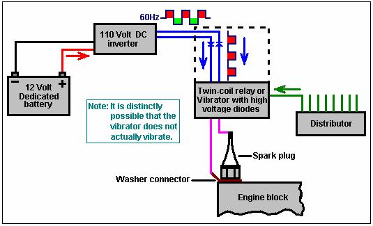
1 A Car that Runs on Water Alone: Last updated: 15th Sept 2005 In July 2005, an American mechanic released the details of his simple conversion system which allows an ordinary car to use water as the only fuel. The details are as follows: The car, which he runs on a daily basis, is a restored, eight-cylinder 1978 Chevy Camaro with stock 350 (5.7 litre) engine, no computer controls, automatic transmission, stock 4-barrel carburettor and stock fuel pump. The fuel tank has been replaced with a metal water tank with the filler cap vented to release heat and pressure. The exhaust was replaced with a new 2 inch pipe which is ducted into the water tank. The water tank has baffles inside it which also muffles the exhaust noise. The stock exhaust manifolds were used, but they will rust on the inside - custom stainless steel pipes would be best but these were not used due to their cost. All of the stock ignition system is used and no changes have been made. A second battery was placed on the opposite side in the engine compartment. A 400 watt (800W peak) 110 volt 60Hz DC inverter was placed in the engine compartment on the passenger side and a fresh air duct located behind the grill directs air into covers placed around the inverter to keep it cool. When the ignition switch is on, a relay turns the inverter on, the relay lead contains a 20 amp in-line fuse. This relay only turns the inverter on and off and has no other function. The inverter is connected to the battery via a positive wire and a negative wire (not the chassis). The inverter is not grounded to the car at any point and instead, is carefully insulated to ensure that accidental grounding never occurs. The wire which would normally go to the spark plug is replaced by a wire which is taken to a box containing one pre-war mechanical twin-coil relay or vibrator per cylinder. Each of these wires drives its own dedicated relay, the current energises the relay coil but the other side of the relay coil is left unconnected. The wiring arrangement is shown in the diagrams below. It is important that the electrical feed to each plug is fed via one wire to the plug cap and a second wire connecting to a washer clamped under the spark plug. This wiring is repeated for each of the spark plugs. To emphasise this, each spark plug should have two wires running to it, one to the cap and one to the washer clamped between the body of the spark plug and the engine block. The wiring is done with 12-2 wire which is 2-core solid copper wire American Wire Gauge size 12 which has core diameters of 2.05 mm giving 3.31 sq. mm. per core, the nearest SWG size is 14. The under-plug washer can be made by bending the end of the solid core into a circle of appropriate size and then flattening the wire slightly. In the relay box, the relays are positioned with a one-inch gap between them. It is important that the physical construction insures that all of the high-voltage connections are fully insulated should anyone open the relay box when the inverter is running. The batteries used are deep-cycle types with high cranking current ratings this is important because the inverter must stay on when the engine is being started and it will cut out if the starter motor current drain pulls the battery voltage down excessively. The alternator is the stock 95 Amp type and it charges both batteries simultaneously. When the engine is started, the relays are heard clicking until the cylinders fire and after that, no sound can be heard from the relays. It is distinctly possible that the relays take up a fixed, immobile position when the engine is running. The diagram below marked Effective circuit is based on that assumption, and it should be stressed that all of the diagrams are only what I understand from the information provided to date.
2
3

4 The engine timing has to be retarded for the car to run off water. This adjustment should be made to the point where the engine runs the best and this is likely to be different for each make of engine. The Chevy Camaro engine runs best with the timing retarded by 35 o. The spark plug gap used to be 65 thou. but is now set to 80 thou. (0.08 ). The plugs used are the cheap Autolite (25) copper core type. Using carburettor jets two sizes larger than normal, allows the engine to produce more power and rev higher than tick-over. The engine tends to knock when first started from cold but it is likely that this can be overcome by using a heater on the water feed to the carburettor, raising the water temperature to say, 120 degrees Fahrenheit and fitted with a thermostat to disconnect the heater when the engine reaches its normal operating temperature. This car has been run 30,000 miles on water alone and covers some 300 miles per gallon as much of the water vapour in the exhaust condenses in the water tank. The disadvantages: the car runs with slightly reduced power and the exhaust system will rust unless stainless steel replacements are used. The inventor of this conversion wants to go on living a quiet life and does not want the nuisance value of high levels of interest. Consequently, he wishes to remain anonymous. He says: I didn t build this to sell or to get a patent on it, or make big bucks from the information. I did it because I could and I did. The only thing I can add is just try it. Some points of note: A car with this modification produces NO carbon dioxide and NO carbon monoxide, but since air is mixed with the gas combustion, it is likely that the greenhouse gas Nitrous Oxide is produced. But Nitrous Oxide dissolves reasonably well in water, so since the exhaust gasses are passed through the header tank which contains the water fuel, it is likely that this engine arrangement is a good deal greener than most. The vented filler cap arrangement will not suit many European car designs which have a locking flap covering the filler cap. For these cars, it would probably be better if the gas exiting from the water tank is passed through a normal exhaust pipe, and the filler cap be a screwed airtight fitting. Excerpts from the Yahoo watercar and egaspower groups mail about this modification: s1r9a9m9 (the inventor of the modification): Hi, I m new to the group and I think this might be of interest to the group. I tried to put this in the Files section but it wouldn t accept it there, so I put it in the photos section under s1r9a9m9. There are 7 pages. You should be able to print off the pics with no problem. I built this car and still drive it. I will be around now and then to answer questions if I can.
5 s1r9a9m9: With the right arc inside the engine cylinder, water will expand very quickly pushing the piston down with more force than gasoline can. This is not a steam reaction and the hydrogen does not have to explode to achieve the reaction needed. I did it with 110 volts at 20 amps per cylinder. I have placed some files in the photo section here. Michael Price: Are you saying that you have a water powered car? s1r9a9m9: Yes the car is driven daily and I have had no problems so far. The egaspower group has the pages in the files section. Their link is in the 'Links' section here. There are other posts on that group about the way that I changed the car over. awrj2000: Some questions: 1) In diagram 5 you left out the ignition coil, it shows 110V ac going to the plug, in the text you mention using the coil. 110V ac on a Bosch Platinum + 4 Plug does nothing. However connecting the 110V ac through the coil creates a nice plasma flame for about 1 second on the plug. My inverter has a ground fault system that shuts it down. (750W Continuous, 1500W Peak, Modified Sign Wave, Creator: Vector, Purchase: Wal-Mart Automotive Section $80.00). Pushing 110V AC on a 12V DC Pulse automotive ignition coil causes some problems: 1) Heat- Running for long periods of time will cause the coil to melt and be destroyed. 2) Arc-Over- If your spark plug dies, becomes open, then you will be shorting the high voltage at the top of the ignition coil to ground, Path of least resistance. Voltage Estimate: 12v through coil = 1000 to 1500v out varies with coils 120v through coil = 10,000 to 15,000v out Again Estimate 2)Ground only at base of Spark Plug??? Spark plug is metal. This metal threads into metal engine. Entire engine is now grounded. Engine has a large ground wire that connects to the body of the car. Entire car is now grounded with the 110v wire. In AC you have Power wire (Black), Grounding wire (White), Grounded wire (Green) You must be using the Grounding (White) and Power (Black) wire. This shows the need to keep the Inverter Isolated from the rest of the car. Keep in mind I have NOT run a car by this method, just trying to figure out some details. Max. RPM: Note: this is one cylinder of the 8 cylinder engine. 500 RPM Idle (8 RPS) 8 Hz well within the 60 Hz ac Strong plasma arc RMP (60 RPS) 60 Hz just enough that if the ac is in sync. with the timing then it will work.(weak plasma arc) Anything above this and the Coil will not energise and to create the plasma. How does a car do it then?? Cars use the distributor: Faster it spins the higher the Hz. In this the distributor is used to pulse the constant 60Hz AC. Theory of operation: Plasma can separate H20 I ve seen a patent on it but don't remember the number. The HV Plasma Arc separates and
6 burns in one process. End result is water out of the tailpipe. Why not change the rotor over to 12v dc, then use 12v dc relay? It seems it would work better if you have 1 coil for each spark plug ignition coil would stay cooler. (Auto Zone cheap coil: $10.00). My inverter Draws little under 90 AMPS (3 x 30 amp fuses) at max. load - spark to ground is 0 resistance and therefore Max. load. 90 Amp alternator would barely keep up. Again: Keep in mind I have NOT run a car by this method, just trying to figure out some details. s1r9a9m9: Oh the confusion: The coil is in the top of the distributor cap as a stock Elcamio 350 engine has. Sorry - I left this out. The inverter does not put out full load at all times, it only uses what it needs, this is never the total of the power of one battery, the second battery is for the other stuff on the car but both are used in the whole system as needed. Ah yes the cheap Auto Zone coil: put one on our jeep and cost $ towing plus the $28.00 for the coil. If you re going to use a good coil use a MSD? ( MDS ). These coils will give out a triple spark at 80,000 volts and 2.83 amps. These are killer coils and they make ignition modules for vehicle too. Buy cheap and stay cold - just buy the good stuff to start with. The Bosch Platinum plugs have stranded about 50 people that have brought their cars to me to repair, I don't recommend these ether but maybe there is a good one out there somewhere. I am using cheap AC plugs in the water car and only replace them every two months, if needed. I did tell Brad NOT to use the 110 on the auto coil it will blow up because it was designed for 12 volt use only. The coil fires the relays only. An earlier post suggested that it may be piggy-backing to the plug as well. I don t now about this, I don t have the equipment to chase the fire down. Most automotive coils fire a voltage around 28,000 to 48,000 volts at 0.87 amps. Simple one this: call a parts dealer and ask the voltage on the coil for your vehicle and see what it is. Crunching numbers is a way to tell some one how close to get when they are trying something new. BUT once they have got it to the point where it will run, the numbers will change a bit and slight changes made to make it run better. The numbers will change for each application. As with my car, the coil will put out 48,000 volts at 0.87 amps, BUT when in use it only puts out 35,000 volts at 0.85 amps. The heat of the engine makes a difference as well and will increase or decrease the numbers. Grounding at the base of the plug ends the 110 at the plug, it does not have to travel through the body to get to where it is needed and there is no static on the radio either. If you use the positive as ground you will short out the 12 volt system burning out all electrical wires in the vehicle. I hope this helps some. MastahScott: Nice to be here and see everyone going in the right direction. I do have a problem with the water car concept for a few reasons: One is because you keep saying that 110 volt gets finally grounded at the spark plug but this does not hook to ground - they are one and the same my friend. The engine block IS ground and the body and the battery. It is all tied together. Two, because an engine that runs on water all the time would not last long. There are natural lubricants in gasoline which lubricate the valve guides and cylinders as well as other things like keeping the compression rings from sticking, etc. Those components would rust up without gas if you use water only. Heat would accelerate the process. Patrick: Mastahscott, Just a brief observation. What you say about the engine block being part of the vehicle's earth system is perfectly correct. However, while the 12V input side of the 110V inverter is grounded to that earth, the output (ac) side is
7 floating free. If you have two nine volt battery-powered radios and you connect the negative side of the two batteries together, it has no practical effect as no current flows along the wire. All you have achieved is to ensure that both radios have the same voltage (relative to the Earth) on their negative rails. s1r9a9m9's design takes his floating 110V supply along two separate wires and attaches ONE side to the car's earth via the screw threads on the spark plug. This is irrelevant as far as the car's earth is concerned because the other side of the floating 110V is connected to the cap of the spark plug and NOWHERE else. This is exactly the same as connecting the two self-contained radios. No current from the 110V system flows through any part of the car's earth (even though one side IS connected to the engine block. The current flows along the two wires and through the spark plug, and nowhere else. No ac current flows through the engine block. In my opinion, the major voltage pulse coming via the distributor, energises the relay coil, creating a major magnetic pulse/induced current, which rides along the pair of wires going to the spark plug, the 110V acting like a wave-guide for this energy, while at the same time, modulating it. It may well be that the magnetic pulse also picks up a whole bundle of extra energy (in the same way that Sweet's VTA magnetic device does and Tom Bearden's MEG does) and this helps to create the vital plasma discharge which splits the water droplets into the hydrogen/oxygen gas mix. But that is only my opinion - I can't prove it. Surely the lubrication of the piston rings comes from the sump oil which the crankshaft splashes up on to the walls of the cylinders? In straight 4-stroke gasoline engines, is the lubrication of the valves wholly dependent on an additive in the fuel? I know that 2-strokes do that but aren't 4-strokes quite different? Scotty: Hello everyone. I have followed this forum for a couple of years now and finally find a plausible discussion of the way things work in reality. I'm no physicist or chemist just an old fashioned electronics field engineer. My expertise is primarily GHz work in satellite communications, but I have worked in nearly everything imaginable. Patrick is exactly 100% correct in his description of what is happening in this circuit, as far as the grounds and imposing a modulating voltage etc. I won't even begin to comment on the less than main stream parts of science however. I subscribe to a philosophy that its all simpler than anyone imagines, in fact its likely simpler than anyone CAN imagine. In automotive engines (not small lawn mower engines) the piston rings are lubricated by pressure feed oil from the crank through the connecting rod, through the wrist pin and through the piston to the under side of the rings. An alternative or duplicate route is that oil on the cylinders is scraped off by the top ring and gravity pulls it down through the lower rings. at running RPM this is more of a splash operation than anything else, its kinda hit and miss what rings get how much splash lubrication, hence the pressure oil feed systems. Valves are lubricated through pressure-fed oil as well, both at the guides, and at the rocker arm ends. The old fuels which contained lead, lubricated the valve seat (as well as clogging it and the gas passages) and to a tiny degree lubricated the valve guides. With modern steel or stelite and sodium filled valves, temperatures are not so much of a problem as in the earlier days. s1r9a9m9's work appears to be valid to me, enough so that I am going to begin collecting and ordering some parts and attempt to duplicate what he has arrived at. I will be using a 1986 GMC pickup truck with 350 CID crate motor with about 2k miles on it. Turbo 400 Auto Transmission and 4x4 drive-train. This set-up has a new aftermarket Rochester 4-barrel carb and a stock GM HEI distributor. The set-up is currently rated at 260 HP with the carb and HEI ignition. There is NO computer controlled anything and there is no smog equipment except for the PCV valve. As I progress I will create a web link for images and results, for all to see. Not having been actively posting here I suspect my posts would be edited and that is fine, however an original of anything I post will be put on my server page as a.jpg whether it is a text document or an image from the camera. I am a bit excited and anxious to get this into trials. I will first look for an HVAC shop locally that carries the relays. I see nothing else that might be difficult to make or fabricate. All the best to everyone and keep up the testing and trials. I will
8 make it a point to be more active now that something is happening that I can understand. s1r9a9m9: I ll make it simple to understand: the ground is at the plugs. The inverter is not grounded to the car. The relay box is not grounded to the car. Battery Inverter Relay Box Plugs The inverter is grounded by the connection with the battery wires only, the 110 volt is grounded at the spark plugs. Trying to crunch the numbers to make it work on paper has confused a lot of people here. I didn t draw a picture of this before I made it work I just put hands on work to it and did it. I drew the picture after someone here asked for one. If you really want the numbers then you need to build one and then reverse engineer it and write down the numbers you want, but the next person who builds one will have a different set of numbers that they came up with on their project. So this will be the only way to get the big oil company's involved, confuse the masses as always. It works, it isn t for sale, the info is free. To copy it, you will need to get your hands in grease and oil and build one for yourself. Emil: Additives in the gasoline may help some, but not much. Oil from the bottom of the engine is pumped to the engines extremities thus oiling the engine. Also, water is actually injected directly into the intake of high performance engines in racing thus increasing power cleaning the engine and reducing the need for as much fuel. In the engines in question, water is not injected into the engine, water that has been split into its components, hydrogen and oxygen, is injected. When the combustion cycle takes place, the components, hydrogen and oxygen, recombine to once again form water molecules. Thus only water and extra air exit the exhaust pipe. Next, being that this water is in a highly excited state, very hot steam, it exits as something similar to very moist air. Ever driven your car in the rain? Doesn't kill or rust it does it? And there you have a car that runs on water. Just needs the right modifications performed. Tom: Patrick, you are a bit off on the function of the relay. The DC voltage from the distributor only triggers the armatures that open and close the AC circuits. There is a question concerning s1r9a9m9's relays as it is not clear where they ground on the DC side and thus they may be grounding to the AC common at the base of the plug. This would cause an additional power surge which may back-up into the inverter. We need some more information here before we really know though. s1r9a9m9: The only things that are not grounded to the car are the inverter and the relay box. All of the original wiring is the same as before with nothing changed. Just a extra battery on the other side of the engine compartment, and connected to the other battery. Why would I isolate the engine from the rest of the car? Keep it simple and others can do it! Tero: Hi s1r9a9m9. Do I understand you correctly, that you are injecting plain water into your engine cylinders and igniting it with a plasma discharge created by the inverter and a standard spark plug? What a brilliant idea! About ten years ago I read of someone who exploded small amounts of water by making an underwater arc with a spark plug attached to one end of a metallic tube. I think the guy was able to puncture 1/4" aluminium sheets with the explosive force of the water. This is really something if it really works in a normal internal combustion engine. I'm really astounded by the cleverness of the concept! s1r9a9m9: I have a well at a spring head where we get some of our water. I have used city water in it as well; no difference in it. Mike: Did you try using an extremely high output 12v coil, such as a racing coil, or even try using two 12v coils to make a big spark? A while back, a friend of mine put an electronic ignition set-up off a 91 Toyota Corona on to his 85 Corona. He
9 reckoned that he got better mileage due to a bigger spark??? I'm sort of picturing using a dirty great V8 coil on a small four cylinder engine. Would this allow a bigger spark gap, and bigger spark, make big mess, or just not make enough of a difference??? s1r9a9m9: I tried a high-output coil but for some reason it didn t work. The 110 volts at 20 amps arcs better than the 12 volt 0.87 amp system on the plug. Don t know the math to it, but it works well. Mike: Cool, I'm gonna give your idea a go. We have 240v in N.Z. should I go for same size (750w) inverter, or being double the voltage, go for half the watts? My victim car is a Fiat X1-9, similar to the Toyota MR2, smaller motor (1500cc SOC), but it has a wee boot behind the motor, so I've got heaps of room to put stuff, and if I can get it working, I'll get a dirty great V8 to play with. Do you use electrolysis as well, or are you running your car on straight water? Your help is much appreciated, s1r9a9m9: The fuel used is just water. The inverter should be 750 watts or larger. I m not sure about your donor car. Does it have a computer or smog controls on it? This stuff is not needed. You will need - A manual fuel pump on the engine. This helps heat the water some. A carburettor that allows the jets to be changed - they need to be larger. A points-style of distributor helps but any type will work provided that it is not computer controlled. I had a Fiat 600D years ago, it was a 1962 model. It would have been a good donor car. Mike: Thanks for your reply. No, there's no guff on the motor, and they are still quite common here (the motors for them). I am looking round for an S.U type carb to modify to fit, they have a much larger range of adjustment. I'm gonna make a wee heater to get rid of the cold knock, I'll get an inverter with two outs, and destroy an electric jug, with a switch on it. Wish me luck. P.S. Have you tried adding antifreeze to the water to help reduce corrosion in the fuel pump and carb? s1r9a9m9: I use a small bottle of baby oil in the engine when I change the oil, and a little in the carb before I let it sit longer than 2 weeks. Ever see rust on a baby's butt? The intake vacuum of the engine helps oil the valves and helps prevent rust as well. Steve: Hello. Thank you for sharing your design with this group as well as the Egaspower group. I have a question about grounding the 110V to the base of the spark plugs. Did you ever experiment with isolating the 110V to only the spark plug by using an isolation washer, similar to a spark plug indexing washer, but made out of a non-conducting material between the base of the spark plug and the motor? Would it still fire and run in this manner? Would this open up the possibility of being able to use this ignition design on cars with electronics? Just curious? I am still looking for a suitable carburated, non-smog, pre-1975 vintage donor car. In California, cars built prior to 1975 are smog test exempted, so then no government agency would know that I have a car running on water... s1r9a9m9: A simple connector can be made if you bend the 12-2 wire in a curve around the plug s base and then flatten it with a hammer a little, so that it will hold its shape when you tighten the plug. Some plugs don t come with the washer that goes under them. Why would you need a computer on a car to control the engine if you use water as a fuel? Tero: Here is an interesting link about experiments regarding exploding water with a plasma discharge. This is very well related to
10 s1r9a9m9's claims to explode water in his engine with a plasma arc created by his 110V AC inverter. In the links case, they explode liquid water with a hefty capacitor bank that is charged up to several tens of kv. This makes for a huge electrical discharge pulse across the spark gap which practically vapourises the water and creates a huge shockwave. s1r9a9m9 uses water vapour or steam in his engine cylinders instead of liquid water which could explain the relatively low energy needed to explode the water... Norman: I would suggest one use a small lawnmower engine to test and develop this in the garage first and then when refined move on to the auto... It will teach you a whole bunch safely in the garage and not out on the road where you might need a tow truck to get back home... s1r9a9m9: Resetting the timing on a lawn mower engine is hard to do, you will need to remove the flywheel and change the shear pin setting. This involves welding the old cut and cutting a new place to set the pin, and getting this right is very hard to do. There are other methods that could be used but that would involve changing to an electronics controlled system. Tero: Does anyone know where to get an electronic easily-adjustable ignition system for a single cylinder lawn-mower type engine? It would be great if you could advance or retard timing just by turning a knob. It's not very difficult to do adjustable electronic ignition timing by yourself with an optical encoder connected to the engine shaft, but I'd rather get a finished product if available. Norman: There are magnetron ignition systems for small engines and my local mower shop said they could get them. Check them out because they may be adjustable like you need. s1r9a9m9: You could move the coil around to do this but the way the engines are made it might prove hard to do as well. Maybe a plate under the coil would be useful. I have been working on a generator with an old chevy 305 v-8 engine which I had in a old truck that I scrapped. I found a new gen head pto driven 65,000 watts. If I get it going, I'm going off grid with our power. John: Would a mechanical relay react fast enough to let each cylinder fire at the correct time? Tero: Many people have asked that, how is it possible that s1r9a9m9's relays are switching so fast that they are able to run at high engine RPMs without melting or breaking? But what if his relays are not switching at all... s1r9a9m9 says that his relays are powered by the High Voltage pulses from the distributor (the coil is in the cap of the distributor), but he is unsure how the relay coil gets grounded (if it's grounded at all). It just occurred to me that what if his relays are wired "wrong". What if his HV pulses from the distributor & coil are not even trying to energise the relay coil, but instead acting as a kind of pilot spark to the spark plugs to trigger the 110V AC plasma discharge. It could even be that there is arcing between the contacts of his relays due to the HV pulse that makes the circuit to connect the inverter to each spark plug in turn. So his relays would actually act as triggered spark gaps. 110V AC from the inverter itself is not able to make a plasma discharge in the spark gap. But if the spark gap is somehow triggered by the HV pulse from the distributor & coil, you could then have a high power plasma discharge in the spark plug provided by the inverter. Basically the distributor & coil would give a pilot spark to each spark plug in turn and the 110V AC output from the inverter would provide the high power plasma. If this is the case the relays would not be needed at all, but you would need to devise a system to be able to use the triggering spark and the inverter plasma discharge, which s1r9a9m9 may have done by accident.
11 Patrick: Tero, I think something along the lines of what you say is very likely to be correct. However, the relay has a coil which is connected to the high-voltage line from the distributor, and it is quite likely that the massive magnetic field generated by it when pulsed with tens of thousands of volts, is part of the system which feeds major power to the plug. Even if the relays don't directly switch the power ahead of the spark, I suspect they are an essential component of the system. s1r9a9m9: If this is true I could make a higher-output coil for each plug and run the plug wire to it. The coil could fit on top of the plug and just connect the plug wire to it there. The voltage from the HV coil could be stepped up to a higher voltage than before. But where would the extra amps come from to fire the water in the cylinder? 110 volts at 15 amps will give you a shock, but 110 volts at 100 amps will fry you. The extra amps is the main part of how the systems works. Tero: No that wouldn't probably work because you need the amps for the plasma. So you first need to trigger the spark with the high-voltage ignition coil and then use the inverter amps. The trick is in how to make this triggering HV spark across the spark plug and then connect the inverter output across it without breaking the inverter. Connecting only the 110V AC inverter output across a spark plug does not create a spark, you need to somehow make a high voltage transient to start the arc. Do you hear a buzzing sound from your relay box? Can you be sure that your relays are actually switching back and forth? They could also be just buzzing without actual switching (switch only halfway between the two contacts). Mechanical distributor does not have a lag like a relay has. If your system was based only on connecting the inverter output across the spark plug, you could make a dedicated mechanical distributor to do the connecting, which would be much better than relays. But I doubt it would work because 110V AC doesn't spark across the plug without tricks. Mike: To all regarding relays: The reason I am particularly interested is that the relays suggested for use are the same types we supply to the refrigeration Industry. With regard to points in a distributor, these are opened mechanically with the resulting bounce, lag and dwell, however electrically operated relays rely solely on the induced magnetism of the operating coil. In this instance are we expecting each relay to operate, lets say, assuming 6000 rpm, that the relay will operate a hundred times per second? How is the back emf of the relay coil accounted for? Or does it just work anyway? I must admit I am confused but not too doubtful especially if someone claims that it works, you never know!!!!!!!! s1r9a9m9: As with any power supply load, the shorter the distance traveled the more power is delivered to the load. This is why each plug is grounded at the base. When the relay sends power to the plug, it makes more sense to have the ground at the plug than have the ground on the other side of the engine where it would take extra time for the current to travel back to the plug. This would offset the timing even more and make for delayed reaction on acceleration of the vehicle. The vehicle is 12 volt grounded with a 12 volt electrical system and has very little distance to travel. If the 110 volt is also grounded to the 12 volt then there would be feedback and the engine would not run. The relays provide the time lapse for the 110 volt not to be continuously grounded to the engine, this delay prevents the 110 volts from overriding the 12 volt system in the rest of the vehicle. Rex: I don't post much but, when s1r9a9m9 made his posts to watercar I, like others, tried to imagine what was going on with the system he put together. I thought that the spark-plug was creating a plasma and decomposing water to hydrogen and oxygen at least near the plasma, and then resulting in some steam. Now that I have found a.pdf on the net, put out by scientists at Hokkaido University, I am thinking that there may be more hydrogen and oxygen production than I first thought.
12 The pdf is titled Confirmation of Anomalous Hydrogen Generation by Plasma Electrolysis. It goes on to say that "continuous generation of hydrogen above levels predicted by Faraday's Laws is observed when temperature, input voltage, current density and electrode surface meet certain conditions, and guess what, s1r9a9m9 has met those conditions, at least starting at hydrogen production. They state 110 volts and increasing the voltage upward to say 130 volts and that is where the anomalous 800% increase above Faraday s Law is observed. Something is going on here. My congratulations to s1r9a9m9. Now imagine using Mr. Robert Krupa's Firestorm (plasma) sparkplugs with this system. The tweaks and experimentation are endless. I had some trouble connecting to the address so if the link does not work the best way to get to the.pdf is to go to Google and put in the keywords WATER PLASMA HYDROGEN and its the 9th link down. Also, when reading the.pdf they mention ~3000 degrees C but they are talking about hydrogen pyrolysis decomposition. Near the end of the.pdf they mention 80 degrees C to meet the requirement above. Faraday. Remember, you heard it here first. Brad: Is it possible to take some pics of your set-up? I must admit that I remain sceptical about your set-up for the following reasons: 1. No pics. People have asked if you could take some pics but that hasn t happened. That question seems to be avoided by you. 2. I have tried to get a relay to work with the high voltage from a coil, but was unsuccessful. Doesn't mean it can't be done I guess. 3. I tried many ways to get a spark-plug to fire using 110V and was unable to make it happen. Is it possible? Should be. But I have a gut feeling that something just isn't right here. Just my intuition, I could be wrong. Hope I am. s1r9a9m9: I would be happy to provide photos of my car, but only if my well-being and safety is protected. People here know my name, so my address is public info. There are people who are waiting for me to make the mistake they need to start their dirty deeds towards me and my family. There would not be much to see in pictures anyway as the only thing you would see in the engine compartment would be the two batteries, the relay box and the cover which helps to cool the inverter. Everything else is stock stuff. I have avoided some questions because it would involve sticking my neck out. The info has been free, detailed, and even some new ideas accepted on my part. I didn't give up on the car, so why should I give up here? I will continue to help as and when I can, but no photos will be posted showing any part of the car - the car has been in car shows, so you can see that people would know who to call and bother. The info I have given is enough to build the conversion and make it run. There has been some good input and ideas given to help improve this system. The maths level needed to do this conversion is = 4 it is simple to do - just do it. I don t have any further information on the relays which I used. If you want to experiment, then you must try the experiment under pressure with the pistons in motion. The compression in the cylinders is 165 to 180 psi. in each. The engine turns over 4 or 5 times before it starts. Repeated compression and the right amount of fire in the hole and it will work. This is not rocket science, it s simple hands-on work. Understanding all aspects of how it works is not needed. Not every one has a donor car, but your friends or co-workers may have one, car that fits the profile will do. If you need info on the change-over of your donor car just ask. Bill: Thank you s1r9a9m9, I understand totally. Brad: Hi s1r9a9m9. As a matter of fact, I do have a donor car - 2 of them. An 86 Camaro with a barrel carb and a 68
13 Mustang with a carbed 289 with the distributor in the front where they belong. I just can't for the life of me, get over how them plugs are firing, so I guess I'll just have to drag my sorry ass out there and hook it all up and see what I can come up with. Now do I want to possibly destroy the 350 or the 289: Decisions, decisions! OK, you got me. Question: The HV out from the car coil is hooked to a relay. Where is it hooked to the relay and where is the other end connected to? I know the contacts are connected to the 110V inverter going to the plugs. Do you have one of the 110V always connected to the plug and the relay contacts in between the other 110V wire? Are they DPDT relays? Hopefully I haven't offended you. I'm just trying to get to the bottom of this and now I'm just gonna do it. Thanks. s1r9a9m9: Good donor cars. The Camaro has a computer on board, I have one with a v6 vortec. The Mustang will be the better bet as the car won t need to be modified. Just print off the diagram and use the parts listed. Don t change the fuel tank or exhaust at this point in time. Just hook a hose to the fuel pump from a separate tank of water, you won t have to mount anything on the car either. Hook up the inverter, then the relay box and finally, run the wires. Do make sure that neither the inverter nor the relay box get grounded to the car anywhere except at the battery connections and the plugs. Check the plugs to see if they are clean and clean them up if they need it. Good plug wires help too. Just to get running, you won t need the second battery. The only thing to change is the timing, just turn the disc. cap until it starts. You don t need to change the jets now, it will idle but won t rev at this point. You may need to adjust the jet screws to allow more water into the engine. See - no major modifications needed to test it, are there? As I said, it is simple. A good inverter only costs $50 - check at Wal-mart. The relay brakes contact on both wires from the inverter. Mark the disc. cap before you move it so you can reset it if need be. The water in the engine will not be enough to hurt it, you can always put it back on gas and run it for a while. Quacker state motor oil draws water into the engine to help cool the oil down faster. It always leaves a milky gunk in the valve covers. If it does lock up, just take the plugs out and turn the engine over. John: Water in a fuel system will cause problems because the water sits in the bottom of the fuel bowl in the pump or carburettor and creates much muck and disasters. The situation will be quite different when there is only water in the pump and carburettor. I service quite a few aluminium and alloy pumps for water in the agricultural industry and water alone is not a great problem. It cannot be compared to the damage done with carbon fuels floating on water. even water without antifreeze will last quite a while in auto cooling systems without significant problems until the heads pit and corrode because of the heating -cooling regime. so don't get hung up on this problem - with water flowing through the system there won't be major concerns. s1r9a9m9 hasn't mentioned changing the filter gauze in the fuel pump and carburettor and this concerns me. The size of the mesh is designed to not allow water to flow through but once again the filter is only designed to allow carbon fuel to preferentially flow through - with water alone, the flow may be sufficient. Filter gauzes used in nozzle filters on chemical spraying equipment are similar mesh sizes and don t impede the flow of clean water. Roger Billings used this system to provide water induction to a hydrogen engine for the US postal service SEE the hydrogen technical papers from the International Academy of Science. Quote "During this contract period, two important improvements have been made in the area of backflash elimination. The first major improvement involved the installation of a conventional gasoline carburettor (connected to a de-ionised water supply) between the gaseous carburettor and the intake manifold. This method of water induction provides more finely atomised water to each cylinder, and is a vast improvement over the previous pressurised sprayer design." So it has been done before albeit for a different purpose. Maybe Roger could have eliminated the use of hydrogen altogether. Willard: Here is my thinking on what happens in one cycle: 1. The spark voltage flows to the coil and from the other end of coil to the spark plug. 2. The spark plug conducts to 30 milliseconds later the contacts on the relay close.
14 volts is now placed through the coil to the spark plug and latched by a portion of the current in the plug. 5. In the gap of the spark plug now is a plasma at 110 volts. 6. As hydrogen and oxygen are separated and explode a higher pressure occurs. 7. The increased pressure causes a higher current to flow and the plasma discharge continues. 8. When the implosion occurs (possibly at the end of the power stroke) the pressure becomes low (possibly assisting the return stroke). Due to the low pressure the plasma is extinguished and the relay drops out. 9. Possibly the exhaust pipe can be restricted so that a good vacuum occurs. Patrick: Willard, I like your suggestion on the operation of the engine - it "feels" right. There are some snags though: At 3000 rpm, my car runs at or above the USA speed limit for public roads, so lets examine the situation at 3000 rpm as being a practical rate for normal running. The power 'stroke' of the engine is carried out in half a rev, or 180 degrees. At 3000 rpm this half rev happens in exactly 60/6000 seconds or 1/100th of a second, which is 10mS (as 1 millisecond = 1/1000 sec). To say that another way, at 3000 rpm, the piston in the cylinder moves from Top Dead Centre to Bottom Dead Centre in 10mS. The other three 'strokes': exhaust, charging and compression each take 10mS each so there is a 30mS gap between successive power 'strokes' on any one cylinder. It gets worse. The ignition spark does not occur at Top Dead Centre. If we assume that the spark is at 30 degrees after TDC, then only 5/6 of our 10mS is available for any useful burn. This means that we are looking at a burn period of some 8mS. I am quite convinced that the HV pulse from the distributor runs down the 110V wire(s) to the plug to cause the initial spark. If I were a betting man, I would give you very good odds on the relay coil being essential to the operation of the engine. Also, I am convinced that the 110V ac creates or maintains the plasma discharge which drives the engine. However, your 15mS is just not possible (unless it powers the following power stroke) because the power stoke has been over for 7 milliseconds when you think the relay contacts close. At that time, the piston is 70% of its way up the exhaust stroke and the 'burn' opportunity is long gone. You and I both think that the 110V ac drives the plasma discharge, so how does it get there so fast? Tero may well be right in thinking that the relay contacts are not actually switching the 110V ac through to the plug. I suggest that the 110V ac connected to the inverter side of the relay contacts is picked up by induction when the massive HV pulse races down the wires to the plug. I think that it rides down with it and creates the plasma discharge immediately. So, why does the timing need to be retarded - if that is so, the spark will occur at the same time as with gasoline and the timing should not need to be altered? I suggest that the process which generates the hydrogen/oxygen splitting of the water droplets is not quite instantaneous and as a result, the explosive burn is delayed slightly. A pointer which might support this suggestion is the life of the relay contacts. I estimate that in 30,000 miles of driving, each relay will have operated 15 million times. This is 60 times the rated life of the relays in s1r9a9m9's spec sheet. He has not said anything about having to replace any of the 8 relays, and while his relays are not necessarily equivalent to those in the spec sheet, and the spec sheet will be giving the most pessimistic assessment of contact life, the relays have been very lucky to have survived 30,000 miles. If, on the other hand, the relay contacts are not being used to any great extent as I suggest, then the relays may well never wear out and the suggestion of replacing them with solenoids might well be viable. I think what you say is nearly 100% right, it's just that the timing forces us to look for some other way for the 110V supply to get to the plug fast enough. Gerry: Hi Guys, I Would like to ask a question: if a pilot arc, say provided by a distributor, is required to ignite the Plasma on the
15 cylinder which is firing, why then can't the 110 volts high current signal be applied to all cylinders at all times, as it would only be on the application of the firing signal that the arc would strike on the appropriate cylinder, or am I off the track here? I guess one problem arising might then, be how to stop the Plasma arc once it is initiated? Well I was thinking of suggesting a high current version vacuum glass encapsulated fast reed switch on the Neutral side of the Inverter output wires. This could be a Normally Open 12 Volt type which grounds the Inverter Neutral wire whenever the Distributor points are open. In this way the 110V ac supply could be fed constantly to all the plugs. Also, reading up on the latest inverters, many of them nowadays, for safety reasons, have their outputs completely isolated from the internal circuitry by having the Active and Neutral wires coming from a separate winding on a double insulated ferrite core. This would reduce somewhat the fears of blowing up the Inverter from feedback of High Voltages (DC) and High Voltage transients to some extent. Other measures like feeding the inverter output through an inductor with a high voltage capacitor connected to ground on the input side of the coil may assist here. Dunno if this helps anyone or not, but thanks for listening. Patrick: Gerry's suggestion of providing the 110V ac to all plugs all of the time is interesting. If you were doing that, you can leave the original spark plug lead in place and just add in the two 110V ac connections to each plug. This raises an interesting issue: On firing, the HV pulse from the distributor will run back along the 110V wiring to the output side of the inverter. Can the inverter survive that? Well, at present, it is highly likely that the inverter is getting it anyway, via induction through the relay coil and possibly via stray capacitance between the wires. This in turn raises a very interesting issue: The HV pulse is not intelligent and does not know we want it to run up the leads to the spark plug, so it heads off in every direction. The induced pulse will head up the wiring to the inverter AND BACK down the wiring which runs from the inverter to the other relays. So each relay is not just getting the 110V ac but gets in addition, a high-speed train of induced HV pulses. At 3000 rpm, an 8-cylinder engine generates 1500 x 8 = pulses per minute which is 200 evenly-spaced pulses per second. So the induced pulses are running at nearly 4 times the speed of the 110V ac, and this pulse speed increases when the engine speed increases. We can't get away from the 8mS period (at 3000 rpm) which is available for: (a) Creating the arc (b) Creating a plasma (c) Splitting the water droplets into gas (IF this actually happens) and (d) Generating high pressure in the cylinder. 8mS ain't long and you have to be done and dusted in that time. The 60Hz supply cycles 60 times in 1000mS, or once in 16.66mS. In other words, we are expecting the 110V ac to create and sustain a plasma in less than half of one cycle (are we optimistic or what?). In any 8mS period, if I am right about the inter-relay feedback, the plug will receive an additional one or two HV pulses. It's not much, but it is slightly better than before. If it is having an effect, then an 8-cylinder engine is much more likely to run than a 4-cylinder engine which generates only half as many HV pulses per rev. Two encouraging things: 1. The car does run, and 2. s1r9a9m9's inverter survives the HV feedback. Any comments anyone? Willard: Patrick, you may not be thinking this through clearly. In a four cycle engine any firing during the other 3 cycles could be bad
16 and certainly does not add any power. Here is what happens if fired at every stroke: 1. The beginning of the intake stroke (a backfire out the intake manifold). 2. The compression stroke (an explosion with no valves open and the crank down). 3. The power stroke (power to the crank). 4. The exhaust stroke (explosion of any unburned gas with the exhaust valve open). Two diodes to each plug will allow the higher of two voltages to go to the plug. The reverse rating voltage of the diode to the low voltage would have to be over 40,000 volts. But these are easy to obtain. As I mentioned in a previous post, I think the coil of the relay is providing isolation between the low voltage AC and the HV. Patrick: Willard, thanks for the feedback. I take your point. I am not sure that the cylinder would be is a position to give a power output during the other strokes, but it might well be able to do so if it got a pulse just before TDC. You could eliminate the inter-cylinder feed on a 4-cylinder engine by using four separate small inverters instead of one larger one. The small ones are fairly cheap and many have overload-protection circuitry so no fuse is needed in the battery lead - those that don't will have their own fuse. With this system, each inverter feeds just one cylinder and the 110V ac feed to each cylinder is isolated from the other cylinders. I think that there is considerable value in having a continuous ac feed to each plug as I am still bothered by the relay timing. At higher revs, the burn period is so short that to get, say, 75% of the available period, the relay has to switch the ac through in maybe 2 milliseconds and I don't think that that is physically possible for any mechanical relay. Also, I can't see the 110V arcing from the input contact to the output contact on a relay which was specifically designed to switch that voltage. It may be that the relay switches the ac through so long after the HV pulse that it accidentally provides the ac for the following HV spark pulse. If so, it is not something I would be keen on relying on. Any thoughts on the subject? Are we sure that 110V ac is essential - the system might work well with pulsed DC so that the inverter output is 0V V ----0V V---- etc. with the mark/space ratio heavily favouring the +110V. If you can do that, then one 110V unit can drive all cylinders with just one HV diode to block the reverse HV pulse. At this point in time I think that we can be reasonably sure that what is needed is: 1. A pulse of voltage high enough to generate a robust spark across a plug gap of say, 80 thou. at the moment the cylinder should fire. 2. Immediately afterwards, a sustained (probably ac) current supply to maintain a plasma discharge through the ionised path of the spark. This supply should probably be insufficient to create the spark in the first place and it should continue to the end of the power stroke or alternatively, for a reasonable length of time, say, 5 milliseconds. It has been suggested that 110V is about right but the only way to assess the effect of 220V ac is to try it. 3. Either some way of blocking the spark pulse from reaching the equipment producing the following-current (perhaps a notch filter or a triac triggered briefly by the higher voltage to short-circuit the incoming pulse), or a following-current generator which can absorb the incoming pulses without being bothered by them. It is starting to look as if a custom electronics circuit might be the optimum drive for a converted engine. s1r9a9m9: OK, I ain t perfect. I found the info on the inverter I used on the car. I put a file in the Files section, with pictures of the book that came with the inverter. The one I used was a 400 watt with 800 peak watts, NOT a 750 watt as I thought I did. Sorry about this mistake - I used the 750W on my work trailer for a power outlet at job sites. My son works for a power company and took one of the relays in for a test. He told me I had it hooked up wrong on the car, and it shouldn t work as it is hooked up. He then ran another test and found that the relay was boosting the amps from the

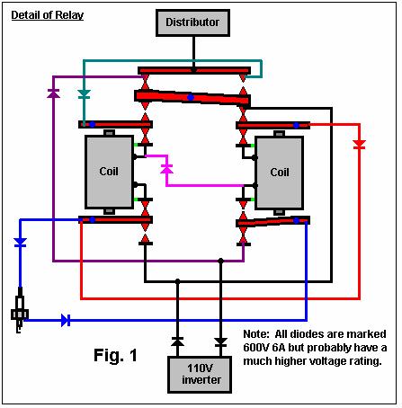
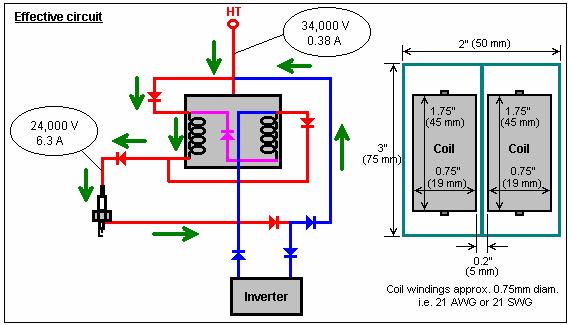
17 disc cap to the plug. The coil output on the car is 34,000 volts at 0.83 amps; the power at the plug is now 24,000 volts at 6.3 amps. The inverter and the relays reduce the voltage and increase the amps to the plugs. The spark advance in the disc., keeps the engine from passing the firing zone when the engine is running, it locks in place because of the time setting. It was a lucky mistake that I happened to find the right wiring to make the car run like this. The relays have double feedback diodes in them rated at 1800 volts ac. This is why there is no feedback to the inverter. They also have a double coil with locking contacts under load. The 4 or 5 turns of the engine when starting, is when the coils get charged and change the voltage and amps to the plugs. Once the coils charge, the contacts stay closed and the coils stay charged. You raise your kids to go to school to learn more than you did in school and what happens? - they show you where you were wrong. Love my sons a lot. I hope this info is more helpful to you all. Here is a picture of the way they are wired up:

18 Please note: The above drawings have been redrawn from s1r9a9m9 s original drawing and so must not be assumed to be absolutely accurate. Fig. 1 shows that the item earlier called a relay is in fact some kind of dual mechanical relay whose operation is not at all clear. The device is unmarked and of pre-world War II vintage. Fig. 2 shows how the diodes pass the distributor pulse to the spark plug. Each figure shows the circuit for just one cylinder and so the circuit is replicated for each cylinder of the engine. Bill: I'm confused??? Is this a triple pull relay? Also on the left coil it indicates that both contacts are closed? What s your take on this? John: Bill, I think this is a multivibrator and not a relay at all. It was the pre-solid state method of making an AC signal out of a DC input, probably from an old telephone system or vacuum tube driver. You will note that there are no connections from the coils to any of the terminals, except through the contacts (I expect the coils are connected to their respective end contacts). So both contacts on one side will be closed to complete a circuit - when power is applied these contacts will open and the opposite pair close and it just keeps doing this at its resonate frequency. There is one thing for sure - it is not operating as a relay in any way at all. I will have to spend a long time studying the flows through the device but from first appearances it may be that the coils are operating as some sort of inductive coupling. It really puts the operating method of the idea into a whole new light because there is no ac going to the plugs at all - the input diodes from the inverter see to that. There also seems to be a direct half wave short across the inverter input as both the inverter inputs are connected to the distributor input through a diode but maybe this stops all the current as it is hooked in reverse to the diode on the neutral input from the inverter. But from first appearances we can bin the idea of a relay operation. This explains of course why the relays are getting such an extended life. It s back to the drawing board folks, cause I don t think we are going to be able to get these beasties anywhere these days, to do a straight replication. Just my first take - now I'd better go and earn a living while I think it through a bit. Bill: Hello s1r9a9m9, after reviewing your drawing of the relay most of the day I'm still confused regarding the operation, so the only way I know of is to ask questions - please bear with me. Your last post you indicated that the top part of the relay
19 would only allow one coil to be energised at a time. Q1. Is this on a rocker or pivot - a seesaw if you will? Q2. On the left side of the drawing it shows both contacts in closed position. If this is the case are the swingers designed to pivot independently in part of the relay layout? Q3. The Voltage input to the relay is 110 Volt + Is the 110 Volt Neutral be use like a standard household plug? Q4. Are all the Diodes utilised of the 600-volt rating? Q5. The power feed to the actual coils is not clear, I see a jumper and diode between the two coils but really no other hookups for the coils except where the swingers are contacting the coil ends - is this where they obtain their power? I apologise if some of these questions seem redundant, but for some reason, I find the drawing confusing. Thank you for your patience. s1r9a9m9: Q1. Yes.. Q2. Double contacts on the bottom of the relay independent of each other under the coils, and double on top but with a pivot point in the middle of the two coils. Q3. Yes. Q4. Yes, the direction is shown as ^, >, < or v. The lower amps allow the higher volts from the disc to go through without burn-out. Q5. The power feeds into one coil and then to the other where the disc cap wire also feeds in, then it goes into the second coil. The ground seems to be neutral at this point. Not sure about the purpose of the ground, other than for the charging of the coils at start-up. The power is in one direction through the relay but the 110 volts is incorporated into the voltage from the disc cap when they go to the plugs. The relays make no noise when the car is running. You can hardly hear the fan on the inverter. They do click a few times when starting the engine from cold, but they stop once it starts up. John: The more I look at this the more I feel that Tero is right and that diodes in series with the HV and AC will possibly replicate what this device is doing, and the coils are incidental to the task. If you trace the drawing you will see that in its rest state, the circuit is just connecting the spark plug to both the AC and the HV through diodes. These old diodes although rated at only 600V will probably handle the pulse at a much higher voltage. I would not trust modern plastic diodes to do the same. I feel it would be safer to use something rated at or so volts, if they are available - my catalogue doesn t list anything over 1000V. Maybe time to get the hands dirty and actually do something! Unfortunately Google gets swamped with all solid state stuff - I only found one mention of this type of gear for driving radio valves and something similar (but single coil) for a model T ford coil driver. Tero: Hi John, I'm thinking the same. By the way, you can build your own high-voltage diodes instead of paying a huge amount of money for dedicated HV diodes: If you need 10kV 10A, you just buy 10 diodes rated at 1kV 10A and put them in series. You might need to put some voltage equalising capacitors and resistors across the diode string, but that is easy to do. I think there are 2000V 10A "ordinary" diodes that could be used. But I also think that a normal diode stands more peak reverse voltage than quoted in the datasheets. By the way, microwave ovens also have one rated at about 10kV and 0.5A for each diode, and some repair shops sell them (I got mine for 5 euros each). Bill: Hello John, If a diode could be located, what Amp rating do you think would be required? Joe:
20 You can pull some tricks when you understand the failure sequence: Ordinarily - when a diode does a reverse voltage break-over - the current rises catastrophically, persists as a near-short till the junction heats & self destructs, usually shorts & then burns open - and then the dead silicon freezes. If you add a lot of series resistance - enough to limit the current heating - they behave like a ratty zener and can recover lots of times. You have to see what else happens when you add that much resistance - might destroy other needed features - or maybe it's tolerable. Note that you see a surge rating - a 1 time in however many ms till you can repeat it - allowable big current for a short time - on the order of x 10 the continuous rating. The lots hotter MSD coils do 300 ma - for 200 us - when it's time. If you were to stick with 1/2 that & hope nobody after you decides to upgrade - should be a safe enough selection. Also - they are power sensitive so since you have pulses - can reduce the de-rating. Understand that every sane designer likes lots of margin till it affects the cost - like millions to buy so a few cents change gets significant. Here, it only has to stay together long enough to see if it works. Tero: Hi, I just built a 12V DC -> 2500V AC (5000V AC peak-to-peak) inverter. I took a Microwave Oven Transformer that had a 230V AC primary with 220 turns. The secondary was turns and the filament winding about 3 turns. The core is rated 1kW. I removed the primary and the filament windings but kept the original turn secondary. I wound a new primary: centre-tapped winding with 24 turns in total ( ). I also wound two feedback windings of 8 turns each. I used two BD249C transistors that I turned on and off with the pulses induced to the feedback windings. The device outputs a nice "square-wave" at 2500V AC and about 75Hz. Parts count: 8. It still needs some work, but as such I get nice blue plasma on the spark plug gap. Joe: Tero, you should increase the frequency until it gets as high as it will still arc under compression pressure reliably. Need that to reduce timing jitter. Tero: I just noticed that the unloaded output frequency is 75Hz, but when it's connected to the spark plug and it's firing, the output frequency increases to about 800Hz. The feedback causes the frequency of the inverter to adapt to the load, which is not ideal because the core is designed for 50Hz. But hey, it works :-) Joe: Find out if pulse-width control is needed first. There won't be a filter cap on the bridge at first - didn't find any big enough from favourite source with a 600 V rating. Will result in a pulse train at the converter frequency. I m not at all familiar with those diodes. My plan is to load the coil with 200K & use the Q1 forward diode drop to regulate the transistor input voltage similar to a zener; could increase R1 if it doesn't stay together. Also - enough pad spacing to stop arc-overs. The 2N2222A has a 200:1 attenuation as drawn, can add a couple meg ohms if needed but would sacrifice arc resistance since the distance needed would rise. Just finished first pass on the artwork mods; would need to add maybe 0.5" to card length if it comes to that - don't need to move anything else to do it. Would keep the standard resistance wire so current stays limited. Seems like a good idea to build in that flexibility, re-space for 1W resistors. Also - opto-isolator comes in a TO-18 package for the part listed; found another that is rated at 5 MHz so might need to change that pattern footprint too. Joe s updated circuit diagram:
21
22 I don't think the divider is in here: use Mohm 1/2 W resistors; might need 4 if you want to handle wide plug gaps; add 1 K from above string to ground, junction to 'scope probe. The 1/2 W is important; affects insulation for arc-over along the divider. New scale factor [for 3] is 4.5 K, do a precise measurement of each - to 1% if you can manage it - so you can correct for tolerance. This is a MANDATORY MOD to get to 150 PSI at 0.032" plug gap. I found today that stiff wires from the battery will break off the card supply plug pins as shown - use better connector or drill the card & tie in place. Have been letting it flap in the wind, pins are too tender to do much of that; need the solder joints expoxied for strain relief. Is idiot resistant in case you get the plug in backwards - fried a chip at 3 a.m. once. It would be helpful to add an ignition switch to the coil - avoids case heating from ON all the time since no series resistor is used, also allows you to handle the card to trim the pot without getting zapped, BTDT. Have a text that shows the coil to have the secondary winding connected at the primary - terminal instead of as shown; makes more sense. Include reference to the 2nd 'repeat' file #; maybe add that to p.3. Used a margin adjust from 'way back to set H & V scale in Paint of.45 instead of the default.75 on all 4; wider effective drawing area. If you don't scale it there - will need to go to a copy shop & adjust the outline to get the amounts as shown or will have trouble getting the chip pins in the drill pattern. Nothing else comes to mind. Patrick: Hi everyone, s1r9a9m9 - thank you for your relay diagram, it must have taken a good deal of effort to produce it. The diagram clarifies a lot of points. It is now clear how the HV pulse reaches the spark plug as it is fed directly there via the diodes. It is also clear that although an inverter is used, no ac is fed to the plug as it is converted to pulsed DC by the diodes in series with it. Without having further test results to hand, perhaps we can predict what is needed to reproduce the water burn of s1r9a9m9's vehicle. Perhaps the following would work: 1. Let the original HV pulse feed directly to the spark plug as it always did. 2. Block the pulse from our extra circuitry with a HV diode. 3. Use the HV pulse to trigger a monostable of say, 5 millisecond duration. Use the monostable to power an astable of say, 500 Hz 100V dc pulses to feed through the diode to the plug. 4 This should be easy to build and test and I think it will work.
23 Any comments anyone? Tero: Having a solid-state electronic device to trigger on a HV pulse is also tricky, because your ICs will smoke if you make one mistake. The HV pulse would need to driven through a voltage divider made of 10 x 1M ohm resistors plus one 100k resistor, which would form a division ratio of 1:100. I just looked at the HV pulse waveform of my 6.5hp garden engine, it is not a single pulse but looks like 1.5 cycles of AC. I also ran a test using a neon sign transformer (outputs 50mA) and a 230V AC->110V AC mains transformer. First I connected the 110V AC output of my mains transformer across the spark plug. It wouldn't strike a spark. If I connected the spark plug across the 4kV neon sign transformer I got a nice blue plasma. But if I connected the 110V AC output to the spark plug and tried to connect the neon sign transformer output also across the spark plug, I wouldn't have a spark because the secondary coil of the mains transformer "shorted" the spark plug out. This system needs blocking diodes both ways. s1r9a9m9 s inverter with it's rectifier bridge is different. I'm not 100% sure, but it may need a blocking diode in series with the ignition coil. s1r9a9m9: The high voltage goes in at the top of the relay and the 110 goes in on one side. The 110 charges the coils in the relay and then it s on stand-by to keep the coils charged when needed. This charge in the coils, changes the high voltage to a lower voltage and higher amperage as it passes through on its way to the plug. The sides of the relay were removed so it could be used in another project. I don t know why it works this way, but it does. When my son drew this up, I had a few questions for him as well. Why the 110 floats is uncommon, but it does, and the high voltage passes through without interfering with the 110 stand-by. The HV has no place to arc inside the relay as it has heavy insulation around all wires and the coils. It is evident that the 110 ground is at the relay, and not at the plugs. The relay is the load. The HV connects with the vehicle ground and grounds at the plug. For some unknown reason, the system will not work without the ground wire for the relay running to the base of the plug - I knew I should have taken that class in rocket science! A meter shows no reading between the ground wire and the plug base when the engine is running, or as it starts, The engine just won t run without the ground wire being in that position. Patrick: Joe, my apologies, I had not realised how close your circuit diagram is to what my last Group was suggesting (that's me being slow on the uptake again). If we get this style of circuit up and running, perhaps a later mod would be to use a car's electronic rev-counter circuit to adjust the length of the monostable pulse so that the burn length is proportional to the current engine speed. What do you think? I came across a couple of diodes on offer yesterday: the 1.5KE400CA transient suppressor diode WE 1.5Kw 400V bidirectional and the 1.5KE180A transient suppressor diode WE 1.5kW 180V unidirectional. Not having seen these before, I gather that they soak up voltage spikes above their rated voltage. I can't seem to see any spec of how high a transient they can handle. Have you any info on them and would it be worth incorporating one in the circuit to help protect your electronics? Presumably, one of those would limit the incoming HV spike to 180V or 400V? A question in passing: will your 2N2222A not get fried if 35,000V gets applied to your divider chain? Won't you get some 175mA driven into the base as it is common-emitter? Pardon my ignorance, I'm only self-taught in electronics. Tero: I have managed to make 110V DC 50Hz to strike a spark in a spark plug gap by using a HV trigger spark through two 5kV diodes.
24 The 110V DC spark is not continuous, but intermittent, while the trigger spark is continuous. Using higher frequency (e.g. modified inverter for example) and perhaps higher voltage (250V DC) should help to get the 110V DC firing more consistent. I observed that the spark plug electrodes tend to "weld" together because of the use of pulsed DC. The 110V DC spark is extremely bright and yellow. In this sense it would be better to use AC to avoid welding, but how can you achieve the triggering with just diodes if you do that? Brad: s1r9a9m9, Have you ever taken a sparkplug wire off and connected it to a spare plug to see what the spark looked like? s1r9a9m9: Bright blue with a white flash up to a 1/4 inch around the tip and gap. Tero: Great! This is exactly what I saw in my test with the HV-triggered 110V AC arc. The bright blue is the standard ignition coil spark and the white flash is the 110V AC arc. I have a good feeling about this... For so many years so many of us have been chasing something, overunity" or whatever, but this time this could be it... Thanks s1r9a9m9! Here is an idea how to make a custom inverter (by using a ferrite core transformer from a commercial inverter) to create HV trigger pulses between normal inverter high-frequency output pulses. The output frequency is the same as original inverter switching frequency (typically kHz). This circuit drives each spark plug separately and can be switched on and off with a simple logic signal. No switching is required, but each spark plug requires it's own inverter. The output waveform is AC for both HV trigger and normal pulses which reduces electrode erosion. It would also make sense to use fast diodes instead of the ones I have used (P600M and 1N4007). I noticed that the diodes do not switch quite fast enough, as they are designed for 50Hz sine-wave operation. The inverter output is basically square wave with very fast rise times. Also the ignition coil rise time is extremely fast and the 50Hz diodes don't "suppress" voltage spikes quite fast enough. A good fast diode could be: BY : 5A 1000V 0.2us

25 Willard and Jack: Jack and I did two successful experiments yesterday. Here is what we did: We built up two HV rectifier banks. Each was good for over 40,000 volts. The diodes we used are 1000 Volt, 1 Amp. We used 48 in one diode bank and 58 in the other. We put a 1 meg ohm resistor across each diode to make sure that the voltage divides equally. One bank was connected to the spark coil and the other to the output of my microwave oven transformer. The variac was set to just below the arcing of the spark plug. Then firing the spark coil caused the plasma to start the arc from the microwave transformer. If we set the variac low enough the plasma would stay for a few seconds and then stop until the spark coil was fired again. Then it would stay again for a few seconds and so on.
26 Then we decided to try using the DC of the Microwave Transformer set. We wired in the bank of diodes that had been used with the microwave transformer and its capacitor (a volt oil filled) before our bank of diodes. We put in a currentlimiting resistor between our bank of diodes and the microwave s bank after the capacitor. We started with 1000 ohms here and gradually reduced it down to about 40 ohms (we where afraid to go lower for fear of blowing our diode bank). Each time we reduced it and tested it we got a louder bang when the spark occurred. At one point we had two 500 ohm resistors in parallel and one opened up. This was the loudest bang of all as the open resistor had a bigger arc in it than the spark plug. So the choice now is do we want a powerful single spark or a longer plasma arc? It appears that the hotter the air in the plug and the moister it is the lower the voltage needed to maintain an arc once it has been started. Our results with DC are the same as with AC, as the peak voltage is the same, whether the current is rectified or not. When we put a drop of distilled water in the plug and fire it, the bang occurs and in addition, several after-bangs occur as water runs down into the gap. This is with the capacitor in the circuit. If we use a drop of tap water we can see electrolysis occurring before we fire it. But the amount of E-gas would be minute. We can see wafts of steam rising from the plug but they are never pushed out by any force as you would have in an explosion. We are wondering if the steam is the only thing running s1r9a9m9's car. We welcome your comments. Ronald: The coils make a difference. The diodes are steering the collapsing spike into the plug. With no coils I get one HV spark arc at 20 Hz 50% duty using a 555 pulse generator. With a coil set connected as they are in the s1r9a9m9 drawing, I get two arcs in the plug gap. The sound is different...there are two individual times these are arcing. It's a double arc. This is not theory or conjecture on my part...i did it. Have seen it. A coil in the mix makes things different. I don't know if it makes things better. Out of several types of coil, the one that made the most difference was the 2" x 2.5" #8 AWG magnet-wire, two independent overlaying coils over the same core. First one has 13 turns and the overlay has 9 turns. Core is S-320 soft iron-shot/epoxy torroidal (hollow) with 1/2 inch steel bolt through it. The further the core is inserted, the louder and more vicious the sparking activity becomes. I'm using an old Chevy 20,000 volt ignition coil pulsed by a 20 Hz 50% duty. This is just talking about the HV spark. Power source is a 12 volt 8-battery bank. Switching is done by an IRG4P254S IGBT. There might be a better ratio of turns or size of wire that works better. I just experimented with some coils I had lying around which I had made for other purposes. Tero: This does make sense. I will have to try it myself. Do you get two 110V AC inverter arcs or two ignition coil arcs? I experimented yesterday with capacitor discharge into a spark plug. The set-up is what Peter calls "S1r-Tero" - the low and high voltage sources connected through two HV diodes to a single point. The spark plug is connected between this point and ground. It probably doesn't make a difference in the car if you get two ignition sparks (as they are just pilots for the big bang discharge through the inverter capacitors), but it could make a difference if you get two 110V AC arcs. In this case I didn't use an inverter as a low-voltage source, but a flash circuitry out of a disposable camera. It consists of a 120uF Photoflash capacitor that is charged to about 300V DC in about 5 seconds from a 1.5V AAA battery. I soldered two wires to the Photoflash cap terminals and connected it to the diode-spark plug circuit. As a trigger I used just an ignition coil connected to 12V battery through a switch. Ignition is manual by closing and opening the switch. The cap discharge to spark plug is an extremely loud and sharp BANG. It does not work so well with a drop of water between the spark plug electrodes, but it does still arc if you spray water on it. The discharge bang can be "slowed-down" by putting an inductor in series with the cap discharge path, which also limits the

27 peak current. I used a 1.8mH loudspeaker cross-over filter inductor. This changed the discharge characteristics to a much smoother POOF instead of sharp BANG, and the arc was more "plasma-like". A relay solenoid coil could be used in it's place, but inductance is a lot higher. The discharge energy of a normal ignition coil is about 0.045J (equivalent to discharging 1uF 300V cap through ignition coil primary, this is how CDI ignition systems work). In my capacitor discharge experiment the discharge energy is E = 0.5*120uF*(300V)^2 = 5.4J. Thus the diode circuit uses about 0.045J energy to trigger a 54J discharge, or the circuit acts as an energy amplifier with a gain of 120. It's also interesting to note that my 230V AC inverter has a 100uF output capacitor that it charges to 300V DC, which is 4.5J. If the spark plug fires 100 times per second you need 4.5*100 = 450W of continuos power to be able to charge the output capacitor fully between bangs. Next I'm planning to build a system where I continuously charge and discharge a 100uF capacitor through the spark plug at about 50Hz frequency. Ronald: Gentlemen, I took my double coil (the one in the photos section) and placed an old SPRAGUE BUFFER ( ,000 volt) capacitor from the top of the plug to the base., cathode to hot. (part number MD-D2). It increased a 3ms spark from a 20,000 volt Chevy coil so much that it screeches when it fires. Very bright. Haven't tried it in the motor yet but I thought it was significant enough to mention. If you wind a coil like this make sure you wind both layers in the same direction. There may well be a better ratio of turns and a better way to amplify this. I just used a coil which I had already made. So the path is: Chevy coil >>>>>>>inner layer (13 turns) >>>>>>>outer layer (9 turns)>>>>>>>plug w/ cap between top and base. It's just pretty impressive, folks. Kinda scary even. Russ: I've also presumed that the rationale for lowering the Voltage is to increase the amperage potential while utilising conventional/inexpensive sources of sparking power, since higher amperage is necessary for efficient water gasification. Since water vapour is the primary fuel (which turns into steam), electrolysis should be limited only to the amount necessary to initiate and perpetuate steam production during the power stroke. Electrolysis limiting is done by current limiting. My point is that although the present challenge may be to provide enough electrolysis, there is such a thing as too much (again, assuming my understanding of the operational principle is correct). I infer that hydrogen combustion is NOT what powers the s1r9a9m9 engine directly because: 1) hydrogen burns too hotly and 2) hydrogen oxidation produces water, which actually yields negative pressure (I've witnessed stoichiometric water-gas produce a vacuum when it ignites & reverts to water).
28 It seems like the efforts to prolong the sparking are meritorious and germane if my surmise re: the s1r9a9m9 operational principle is correct. Do you concur that: 1) Water vapour is pressurised by the compression stroke 2) Some the water vapour is electrolysed into dihydroxy (Brown's gas, etc.) 3) Some of that gas is ignited by the selfsame spark which causes a spike in temperature in the immediate vicinity of that hydrogen oxidation 4) Which turns some of the water vapour into steam (expanding to 1500x the aqueous volume) 5) Which causes a pressure surge within the pressurised cylinder 6) Which causes a consequent temperature rise 7) Which propagates the steam production in chain reaction throughout the power stroke Jim: On item 4), your value is for slightly above atmospheric pressure. At the 11.2 bar you get when the spark is due - you only get x 153. On item 7), Not throughout - it happens within about 10 degrees crank rotation since most of the ingested spray flashes to superheated steam before the spark gets there. Peter: What I m going for in my thinking is to conceptualise s1r's invention (process) in my minds eye. Tero says his spark is gratifyingly loud. Elliot says the flame goes out under pressure. At first glance the idea of s1r's invention is to super-heat water vapour turning it rapidly into steam thus driving the piston down due to the vapour --> steam expansion. S1r says the spark timing is retarded and the water is metered as spray or vapour into the cylinder. OK, then, when the piston starts going downwards on it's power stroke the pressure reverses the effect being that the plug will fire. This overcomes Elliots pressure problem. Now with Tero's big banging, hot spark, it is logical that the steam will vapourise having the effect of providing power. If my memory serves correctly water will disassociate at about 700 degrees, therefore two things are happening: 1. The water droplets vapourise (pressure source one) and the temperature of that disassociates the molecules. 2. The ensuing flame then ignites the Hydrogen/Oxygen mixture thus providing pressure source two. Eugene: Peter, it would be also a great pleasure for me to understand how s1r9a9m9 s car works (if it really does). I believe that Tero s spark is gratifyingly loud because I have also experimented a lot with these things and a 10J discharge performed in open air is rather loud. It could well be that, as Elliot says, the flame goes out under pressure. On water disassociation, if you calculate thermodynamic temperature of such a reaction you will get about 30000K. That is T = E/(Na*k). So to my mind, only a small amount of water will be converted to H2 and O2. I totally agree that the water droplets vapourise. But when you say that the temperature of that disassociates the molecules this is: 1) Only a small amount 2) This dissociation is endothermic so it LOWERS both temperature and pressure in the cylinder if it occurs there. Also, if the Hydrogen/Oxygen mixture ignites, the total pressure will not be higher than it was before, it could only be lower due to unavoidable losses. So we should think further. Tero: If the s1r9a9m9 engine is ever going to run the static test must work. That is, we must get at least some piston movement by turning water into steam with the plasma discharge in a static configuration. The easiest way of course is to use a small single cylinder engine and use a single-shot plasma discharge system. For example with manually controlled ignition coil or other HV source and pulse capacitor discharge from the flash unit of a disposable camera. The engine must be warmed up first by running it on gasoline or by heating the cylinder block otherwise all the produced
29 steam will condense immediately on the cold cylinder walls. This happens in my syringe tests. I don't get any pressure rise and the inside walls of the transparent syringe are covered with tiny droplets of condensed water. The engine should then be rotated manually, water injected and spark plug fired using the discharge capacitor to produce plasma ignition. The piston should move at least a small amount... Here is a quote from where they are injecting flash steam in an engine cylinder through the spark plug hole to make it run: I modified a 11hp Briggs and Stratton engine to accept the L912 Injector. Then set about discharging it while it was installed on the engine. First I rotated the engine to top dead centre on the compression stroke. Then installed the injector, heated it up and discharged it. It was discharging into the combustion chamber of the engine. The injector developed an internal pressure of about 3000psi. If the concept was to be sound, I needed good results from a static test such as this. So I crossed my fingers and discharged the injector into the engine. I was astonished to see that nothing happened. The piston didn't move one millimeter. I was overcome with disbelief. The engine was suppose to turn over but it did not. And I knew that if the engine did not rotate through a compression stroke. In a static test, then it would not operate at speed. Or perhaps not at all. I asked myself what is going on here?. This should work, the results in open air discharge were so fantastic. So I decided to put some more thought in to it. A day or two later I figured out what was happening. Flash steam can form, or condense in a micro-second. Generally you re expecting it to flash instantaneously when your trying to run an engine off flash steam, and this is possible. But it can destabilise just as quickly. And this is what was happening in my experiment. I was producing the flash steam just fine, but the engine block was cold, and it absorbed the flash steam directly into water. It was happening so fast that it was almost producing a vacuum. The room I was working in was air-conditioned and at a temp of 74 F. The mass of the engine block was at equilibrium with the room temperature and since the mass of the engine block was so much greater than the mass of the actual flash steam discharge, it simply absorbed it. This is probably the most important thing to consider when contemplating a flash steam engine. Back to the static test. I then proceeded to take a small propane torch and heat the block and cylinder head of the 11hp Briggs and Stratton engine. First I heated it to 180 F and set up the experiment the same as before and discharged the injector. This time it worked. The engine kicked over about 740 of rotation. At 212 F the results were almost twice as good. In fact, the rotation of the engine was so dramatic the engine almost jumped off the table. This is a very important thing to learn. What is going on in this situation must be watched very closely since it is a relative factor that will affect performance drastically. For example, it has been observed to cause extended run times, in four-cycle engines running on argon. The hotter the engine block the better the performance. It has been observed that ice can form on the exhaust valve stem in engines that are running on argon. And the block is generally cooled by the compressed argon. However, if you heat the block before running the engine, you will always get better performance. So this phenomenon is relative even in nonflashsteam applications, as should be the case. But the effect is much more critical in the case of a condensable vapour such as flash steam. Russ: The popping from a downed power line probably occurs from sudden steam expansion due to heat from high current (just as popcorn 'pops' because of the concussion of steam released from moisture trapped inside the kernels). I'd still like to see mathematical proof that the "explosion" of water is not explained by: 1) Electrolysis & ignition, and 2) Sudden phase change to steam due to heat from a sudden current rush due to the instantaneous HV discharge. The water cannon picture shows a spray of liquid water, but this would result from the sudden depressurisation of steam immediately upon escaping the muzzle. Since there is a relationship between pressure, temperature & time, I'm not convinced that these two processes don't explain the s1r9 power stroke. To iterate: water vapour and air are pressurised by the compression stroke, partial electrolysis occurs, partial H2 ignition occurs, causing heat, which changes some of the vapour to steam, which elevates pressure, which increases temperature, which forms more steam, which continues to propagate in chain reaction during (perhaps the first 10% of) the power stroke. Is it true that s1r9 s HP output cannot be explained thus -- especially in view of the unprecedented application water in a 4- stroke cycle??
30 s1r9a9m9: You people hurt my head, thinking so much about what is going on inside the cylinder that my head hurts. Inside a gasoline engine the air and gas are compressed to somewhere between 85 psi and 180 psi in most engines. When the piston is just past TDC the plug fires and the gases explode as the carbon components superheat under pressure. Inside the water engine, the process is a little different. The water is taken into the cylinder as the piston goes down after the exhaust is released. The piston goes up to compress the water and air. When the piston starts back down, water is on the piston and the head, while the cylinder walls should be clear of water. Just after the piston starts down, (if the timing is set right), a vacuum will form between the water on the piston and the head. Then the plug fires in the vacuum area, creating a hot shock-wave between the water on the piston and the water on the head, most like a dieseling effect. My engine does not have the power it did have, but it s not that much less than before. The rpms at which my engine turns is not 3000 rpm. When I am driving down the road at 55 mph the engine is only turning about 1800 rpm. Each size of engine turns at different rpms for its application. Does the water inside the cylinder explode? - I don t know. Does the water separate inside the cylinder to make a gas, and then explode? - I don t know. Does the water turn into steam inside the cylinder? - I don t know. Maybe I should have never posted this info on the net; it seems to have stirred up more conflict than interest. If you are unemployed, don t waste your money on dreams. Get a job stabilise your life and then build your dreams. The big car makers won t move over to make room for you and your ideas, they will step on you and keep you down. Sure, a car like mine will save you money, but not that much. A tank of gas costs $28.00 and lasts 1 week, that s $1,456 in one year. The changes which I made to my car were done using stuff that I had around the shop and help from friends at the welding shop and that s why the cost was so low on my car. Don t spend money on stuff you may not need, there are people out there who have surplus stuff that they will share with you if you ask, or exchange the parts in exchange for some work. I worked on my car for over a year to get it right, it took that long to figure to change the timing. You will run into the same problems throughout the building of the car as well. This does work, but you need the time and money to spend on it as well. Just because you have all the parts and have it all in place does not mean that it s going to start the first time you turn it over. It is simple to build but to get it right on your car will take time. As far as I can see, no laws of physics have been broken to make this work. It may be a fine line as to how it works, but that ain t for me to figure out. In the cylinder, on top you have a high pressure, in the middle there is a low pressure, and on the piston there is high pressure. What happens between two high pressures when you add a strong electrical charge between them? - It ain t rocket science. Tero: S1r, just after the piston starts down, there will be a vacuum formed between the water on the piston and the head... No there will not be vacuum, but lower pressure than at TDC. Still pretty high. I think Aubug already showed that the water mist that came through the carburettor would flash to steam before TDC due to compression alone. So you most probably have pressurised steam in the cylinder when it's firing. then the plug fires in the vacuum area creating a hot shock-wave between the water on the piston and the water on the head, most like a dieseling effect If you fire a low-power spark or plasma or whatever in a vacuum (without water) you will not get any pressure increase (other than from a little bit of heating). The shock wave is so small that it will not do anything. The same with the spark in high pressure (without water). There will not be an appreciable shock wave. Certainly not enough to run the engine. Does the water inside the cylinder explode? - I don t know
31 It has to in order for the engine to work. Does the water separate inside the cylinder to make a gas and then explode? - I don t know Probably not, even if it did it would contribute very little power. Does the water turn into steam inside the cylinder? - I don t know Yes it does. I think the compression is enough to turn the water mist into steam before it reaches TDC. Even if didn't, the spark or plasma would be hot enough to turn the water into steam. Maybe I should have never posted this info on the net, it seems to have stirred up more conflict than interest We are all grateful that you did! We are just struggling to understand how your car works, because based on the information you have provided (the first schematic with relays) it should not work. Now it seems that the diodes inside your relays are doing all the work. Sure a car like mine will save you money, but not that much. A tank of gas costs $28.00 and lasts one week, that s $1,456 a year Where I live, a tank of gasoline costs about 70 euros, which translates to US$85. If I need a refill once a week, I m spending $4,420 a year. As I see it, no laws of physics has been crossed to make this work. It may be a fine line as to how it works, but that ain t for me to figure out You are breaking the laws of known physics. As mentioned many times, the amount of gasoline injected in a cylinder has an energy of about 3000 Joules. The normal ignition spark contains about 0.05J of energy and my 300V capacitor discharge spark contains 5J. To have the same power with the 5J cap discharge as you get with 3000J gasoline, you would need to get 600 times more energy out from the water explosion than you put in to ignite it. There is no known mechanism to explain this. John: Jonathan, If you are absolutely intent on chasing the "relay" and not proceeding on the ideas of Tero, I would suggest that you start looking at military surplus. After a fair bit of reading I suspect, but have no proof, that it is a mechanical chopper for transforming DC current in a radio power supply from possibly an Airborne Warning System (AWACS?) probably from the late 50's or early 60s. Another possibility is the same thing for a turbine ignition circuit, or a heating combustor igniter from the same time period. There is very little on the net and I m out in the country and haven't access to a good technical library here. But the very robust design, suggests military, and none of the civilian designs I have seen use two coils. Because there is no external supply to the coils, they are powered through the contacts, and this pretty well defines them as some kind of vibrator. As your friend said; if it were a relay it would need about 14 connections. I can't actually figure out the operation of the device from the circuit that s1r9a9m9 supplied, but it is possible that there is another hidden coil wire, also, the operation of the rocker arm on the top contacts is hard to determine without knowing the spring loadings on the various contacts. I think it is pretty certain that there is nothing available today in the usual relay field which is even close. Tero: I have been wondering why s1r9a9m9's diodes inside the relays don't break as they were spec'd at 600V or so, while the ignition coil produces a lot higher voltages (10-30kV). Could the answer be so simple, that the spark plug does not allow the voltage to rise to very high levels, as the air in the gap breaks down well before the ignition coil reaches is highest open circuit voltage. The electrical breakdown voltage of air is about 1-3kV/mm at 1 atmosphere. The pressure inside the cylinders increases this somewhat, though. I measured the voltage across the normal spark plug while my 6.5hp engine is running with an oscilloscope and voltage divider. The voltage reaches about 4kV before it arcs. s1r9a9m9: I and my son are reverse-engineering the relay that I cut the sides off of and we are going to find newer stuff that can be
32 used for the same use as the relay and as cheap as we can. I found a guy who is 85 years old who knew what the relay fit. It operated two pumps on a 1949 Johnson-Prutte air cooling system. The relay was used to the turn on two pumps, when one would start to get hot the relay would switch the power to the other pump before the other shut down, that s the reason for the diodes in the relay. I'll post the info as soon as we get it together. Since my car is running now, I will replace one relay at a time to test the tech we try. YES, I will keep records of events on this project and take pictures of the stuff needed for the system. I didn t change any of the stock stuff on the engine. The spark advance still works, and stock HEI coil in the cap is GM equipment. The vacuum hoses were all replaced with new ones along with the base plate under the carburettor and behind the heater controls. I know the timing seems way off on the engine, but that s where it runs the best and the smoothest. Other engines may not even have to have the timing changed, I haven t done that yet. I thought I would start a new group to help with storage space here. I'll put all my file in the new group. Any one who needs the space is free to join. Here is the address: groups.yahoo.com/group/waterfuel1978/ Tero: I tested the plasma ignition system in my 6.5hp 4-stroke engine with gasoline and propane (didn't test water yet). I used HV pulses from the original ignition coil as trigger or pilot sparks. I had to reverse the polarities of the bridge rectifier, two diodes and the capacitor to get a better pilot spark. The schematic and details are:
.")
33 I ran the engine on gasoline and propane. In both cases there was an apparent increase in RPM when the plasma ignition system was activated (engine not loaded). There was some plug erosion, but that can probably be solved by lowering the discharge energy (smaller capacitor or lower voltage). The discharge energy is quite high (about 5J) and makes a very nice and loud bang in the spark plug when I pull the start cord with the spark plug removed from the engine. Note: Even though there is DC at the spark plug all the time, the discharge itself lasts only a very short time (so short that it's difficult to record it with video camera at 30 frames per second). Jonathan: S1r9a9m9, thank you again from all of us, to you and your son, for all your efforts in helping us. You are good people, to others and our environment. Also thank you more than we can say, for coming here and helping everyone follow your plans rather than try to make money off of it and eventually lose it in the greed. You and your son are great men. Ronald: Here is the diagram of the way I've got it hooked up at the present time. It's getting simpler. I got tired of blowing up HV capacitors so I just made one from plastic and aluminium foil. Fixed that puppy! We got bang now. Jim: Wow, you learn something new every day. It seems that it requires 5000 more volts to jump the gap if polarity is wrong on the plug centre. It should be negative for more efficiency. This means that the main flow of electrons would be from centre of the plug out to ground. The only problem is the wear on the centre electrode is greater with negative centre, while wear is greater on the ground electrode when using a positive centre. I will need to rethink my view on S1r's circuit in that light. Here s a couple of links on that: Here is what I, initially, think may be going on with s1r9a9m9's circuit:
Page 3. Misc. insulator pads to go under the inverter and spark box. I used the packing material from around a glass jar
 Page 1 Convert vehicle 1978 Chevy Camaro with stock 350 engine, automatic trans. Stock 4-barrel carb, and stock fuel pump. The gas tank has been changed to a metal water tank and the fill cap is vented
Inside a typical car engine. Almost all cars today use a reciprocating internal combustion engine because this engine is:
 Tech Torque HOW PETROL ENGINES WORK The Basics The purpose of a gasoline car engine is to convert gasoline into motion so that your car can move. Currently the easiest way to create motion from gasoline
1. Replace the plugs with the cheap Autolite (25) copper-core plugs, set to 80 thou gap.
 copper-core plugs, set to 80 thou gap.") A recently encountered e-mail from Robert Calloway states that Tesla s bi-filar series-connected coil is effective in picking up radiant energy. In the light of that, and in the absence of further information
A recently encountered e-mail from Robert Calloway states that Tesla s bi-filar series-connected coil is effective in picking up radiant energy. In the light of that, and in the absence of further information
Troubleshooting Guide for Limoss Systems
 Troubleshooting Guide for Limoss Systems NOTE: Limoss is a manufacturer and importer of linear actuators (motors) hand controls, power supplies, and cables for motion furniture. They are quickly becoming
Troubleshooting Guide for Okin Systems
 Troubleshooting Guide for Okin Systems More lift chair manufacturers use the Okin electronics system than any other system today, mainly because they re quiet running and usually very dependable. There
Electrical Systems. Introduction
 Electrical Systems Figure 1. Major Components of the Car s Electrical System Introduction Electricity is used in nearly all systems of the automobile (Figure 1). It is much easier to understand what electricity
1 of 2 9/4/ :27 AM
 Ford Mustang IAC IAB - Solving your idle problems http://www.muscularmustangs.com/iac.php 1 of 2 9/4/2010 10:27 AM Solving idle problems part 1 - Cleaning your IAC Does your idle rise and fall over and
KEIHIN CARBURATORS FOR 4-CYLINDER HONDA MOTORCYCLES
 KEIHIN CARBURATORS FOR 4-CYLINDER HONDA MOTORCYCLES Set of 4 Keihin carburetors marked 089A and used on 1976 CB550K GENERAL NOTES: All carburetors perform the same function: mixing air and fuel for supply
Ventilation System Before Starting
 How Long Should You Crank An Engine Ventilation System Before Starting Any electric start motor should be able to be started using a rope, (unless the motor Someone may have "worked' on it before and flopped
THE MOTOR/GENERATOR OF ROBERT ADAMS
 THE MOTOR/GENERATOR OF ROBERT ADAMS WHEN HE WAS 70 YEARS OLD, ROBERT ADAMS OF NEW ZEALAND DESIGNED A VERY EFFECTIVE MOTOR/GENERATOR. HE WAS TOLD TO DESTROY HIS DEVICE OR HE WOULD BE KILLED. ROBERT DECIDED
Actual CFM = VE Theoretical CFM
 Here is a brief discussion of turbo sizing for a 2.0 liter engine, for example, the 3-SGTE found in the 91-95 Toyota MR2 Turbo. This discussion will compare some compressor maps from the two main suppliers
Comments and facts below in chronological order as testing progress. Added non Added resistive Total load Watt meter kwh resistive
 Comments and facts below in chronological order as testing progress Date Added non Added resistive Total load Watt meter kwh resistive from grid Jan 13 6 + 9 = 15 W 15 W 16 Jan 17 3 x 27 = 81 W 96 W 100
Devices installed in a race car should be divided into two categories: power devices and control devices.
 With the never-ending quest for more horsepower and faster cars, today s racecars have more electronics than ever. To create more horsepower, cylinder pressures must rise. To fire the cylinders under these
Troubleshooting of the LubeTech Grease System
 Troubleshooting of the LubeTech Grease System February 2009 The LubeTech grease system is designed to be a preventative maintenance system that will extend the life of your bearings that are connected
Corrado Club of Canada. VR6 Engine FAQ. By: Dennis
 Corrado Club of Canada VR6 Engine FAQ By: Dennis I thought I would snap a few pics of the engine compartment on my 1994 VR6 Corrado. First, this is the updated engine management system so it does have
BASIC ELECTRICAL MEASUREMENTS By David Navone
 BASIC ELECTRICAL MEASUREMENTS By David Navone Just about every component designed to operate in an automobile was designed to run on a nominal 12 volts. When this voltage, V, is applied across a resistance,
Roehrig Engineering, Inc.
 Roehrig Engineering, Inc. Home Contact Us Roehrig News New Products Products Software Downloads Technical Info Forums What Is a Shock Dynamometer? by Paul Haney, Sept. 9, 2004 Racers are beginning to realize
HOW TO USE A MULTIMETER, PART 1: INTRODUCTION
 HOW TO USE A MULTIMETER, PART 1: INTRODUCTION By: Rob Siegel First, thanks for all the comments, both here and on my Facebook page, about the piece on Electrical Safety two weeks ago. I felt that, if I
CHASSIS DYNAMICS TABLE OF CONTENTS A. DRIVER / CREW CHIEF COMMUNICATION I. CREW CHIEF COMMUNICATION RESPONSIBILITIES
 CHASSIS DYNAMICS TABLE OF CONTENTS A. Driver / Crew Chief Communication... 1 B. Breaking Down the Corner... 3 C. Making the Most of the Corner Breakdown Feedback... 4 D. Common Feedback Traps... 4 E. Adjustment
*Some speedometers have these additional electronic connections. If yours does, then remove the smaller slotted screws shown.
 www.odometergears.com 1981-1985 240 Cable-Driven Speedometers (NOT for 1986 and later electronic units) http://www.davebarton.com/240-odometer-repair.html For this set of instructions below, I will not
Connecting the rear fog light on the A4 Jetta, while keeping the 5 Light Mod
 Connecting the rear fog light on the A4 Jetta, while keeping the 5 Light Mod DISCLAIMER: I'm human and make mistakes. If you spot one in this how to, tell me and I'll fix it This was done on my 99.5 Jetta.
U-Score U-Score AAC Rank AAC Rank Vocabulary Vocabulary
 go 1 927 you 2 7600 i 3 4443 more 4 2160 help 5 659 it 6 9386 want 7 586 in 8 19004 that 9 10184 like 10 1810 what 11 2560 make 12 1264 is 13 10257 on 14 6674 out 15 2350 do 16 2102 here 17 655 eat 18
Disconnect the negative battery cable!
 Understanding Mod-3 on a C90 With Wiring Diagrams By DrJones18LC I do not have a C90 at my disposal (or audio/video equipment for that matter) so I can't make a live step by step how-to on doing Mod-3.
Internal Combustion Engines
 Internal Combustion Engines The internal combustion engine is an engine in which the burning of a fuel occurs in a confined space called a combustion chamber. This exothermic reaction of a fuel with an
THE TORQUE GENERATOR OF WILLIAM F. SKINNER
 THE TORQUE GENERATOR OF WILLIAM F. SKINNER IN 1939, WHICH WAS THE START OF WORLD WAR TWO, WILLIAM SKINNER OF MIAMI IN FLORIDA DEMONSTRATED HIS FIFTH-GENERATION SYSTEM WHICH WAS POWERED BY SPINNING WEIGHTS.
ALTERNATING CURRENT - PART 1
 Reading 9 Ron Bertrand VK2DQ http://www.radioelectronicschool.com ALTERNATING CURRENT - PART 1 This is a very important topic. You may be thinking that when I speak of alternating current (AC), I am talking
CHAPTER 6 IGNITION SYSTEM
 CHAPTER 6 CHAPTER 6 IGNITION SYSTEM CONTENTS PAGE Faraday s Law 02 The magneto System 04 Dynamo/Alternator System 06 Distributor 08 Electronic System 10 Spark Plugs 12 IGNITION SYSTEM Faraday s Law The
Everything Leading Up to Nuclear Cars. next 150 years is to have a car that runs on the splitting of atoms. This will be a clean and
 Ethan Brunet-Bailey Everything Leading Up to Nuclear Cars Engineering is why we have cars, electronics, and everything around us. The car that we have in 2016-2017 runs off of fossil fuels and some are
Asynchronous Restriking CDI 2 channel
 Asynchronous Restriking CDI 2 channel Parts List ARC-2 module Decals Power Cable Fuse Specifications Operating Voltage: 8-20V Operating Current: Max Operating RPM: Ambient Temp range: Ignition inputs:
Trucking Info: Equipment 7 Factors to Consider When Installing an Inverter
 Trucking Info: Equipment 7 Factors to Consider When Installing an Inverter From what size to get to company policies, what fleets need to know when choosing and installing a power inverter. September 2013,
Installation Instructions Diesel Nitrous System (#82028)
") Installation Instructions Diesel Nitrous System (#82028) Thank you for choosing ZEX. If at any time you have questions regarding this or any of our products, please call our Nitrous Help support line at
Installation Instructions Diesel Nitrous System (#82028) Thank you for choosing ZEX. If at any time you have questions regarding this or any of our products, please call our Nitrous Help support line at
Winterizing the Truma-Equipped Winnebago Travato
 Winterizing the Truma-Equipped Winnebago Travato DANIEL SENIE MONDAY, OCTOBER 16, 2017 REVISION 2 Introduction When we bought our 2016 Travato 59G, the manual s instructions for winterizing seemed to not
 Solid State Ignition Replacement May 15, 2005 Introduction: There are two Tecumseh Solid State Ignitions ( SSI ) configurations we are concerned with here: The one on the left I call SSI Under for short
Steve Saunders Goldwing Forums > Steve Saunders Goldwing Forums > Reference and FAQ Forum > Balancing GL1500 Carbs
 Skype update. You can now easily activate Skype in your forum profile, allowing you to talk in real time with other forum members. Just go to MY ACCOUNT, click PROFILE and scroll down to the Skype field,
The Physics of the Automotive Ignition System
 I. Introduction This laboratory exercise explores the physics of automotive ignition systems used on vehicles for about half a century until the 1980 s, and introduces more modern transistorized systems.
The Holly Buddy. 2.5cc Model Diesel - Compression Ignition engine.
 The Holly Buddy 2.5cc Model Diesel - Compression Ignition engine. Firstly I want to dedicate this engine to David Owen. I didn t know David for very long, but his influence on me and my affection for these
PORSCHE V r Valve Timing Instructions. Copyright 2009 Written by Mike Frye Edited my Adam G.
 PORSCHE 928 32V r Valve Timing Instructions Copyright 2009 Written by Mike Frye Edited my Adam G. Sections: Overview.3 Disclaimer/warnings/things to watch for 4 Terms and naming conventions used in this
Solar Power. Questions Answered. Richard A Stubbs. Richard A Stubbs 2003, distribution permitted see text for details
 Solar Power Questions Answered Richard A Stubbs Richard A Stubbs 2003, 2008 distribution permitted see text for details Brought to you by: SunrayPowerSystems.com 1 Contents Introduction... 3 Disclaimer...
Overcurrent protection
 Overcurrent protection This worksheet and all related files are licensed under the Creative Commons Attribution License, version 1.0. To view a copy of this license, visit http://creativecommons.org/licenses/by/1.0/,
RV8 boot lid lock and boot light switch
 Godfrey Dennis has some useful pictures of the lock on the boot lid on his RV8 which he feels should help to clarify the metal tab which acts as the switch mechanism for the interior boot lamp, particularly
Prove all things; hold fast that which is good.1 Thessalonians 5:21
 ELECTRICAL TROUBLE SHOOTING Prove all things; hold fast that which is good.1 Thessalonians 5:21 Electrical problems can pop up at any time and can seem hard to fix but they really aren't. Most of the time,
My Hawk build part 24 by Stuart Clarke. Getting ready to turn the key.
 My Hawk build part 24 by Stuart Clarke Getting ready to turn the key. Things had moved on quite nicely now and the end was virtually in sight. It was getting to that do or die moment when I find out if
INSTRUCTIONS. #82044 Race Diesel Nitrous System
 INSTRUCTIONS #82044 Race Diesel Nitrous System Thank you for choosing ZEX products; we are proud to be your manufacturer of choice. Kit Parts List Description Qty. Description Qty. Nitrous Solenoid 2.088
Common Terms Selecting a Turbocharger Compressor... 4
 TURBOCHARGERS Common Terms... 2 Adiabatic Efficiency... 2 Pressure Ratio... 2 Density Ratio... 2 Turbine... 2 A/R Ratio... 2 Charge-Air-Cooler... 2 Boost... 3 Waste Gate... 3 Turbo Lag... 3 Boost Threshold...
Megasquirt II with V3.0 PCB Stock Rotary CAS Setting up your 2 rotor engine to use a stock unmodified Mazda Crank Angle Sensor with Megasquirt
 Megasquirt II with V3.0 PCB Stock Rotary CAS Last Updated: 2/November/2007 Setting up your 2 rotor engine to use a stock unmodified Mazda Crank Angle Sensor with Megasquirt Read through all of the steps
Wide Band EFIE Installation Instructions. Locate the wide band oxygen sensor current wire
 Wide Band EFIE Installation Instructions Install your fuel efficiency device The EFIE is not intended to be a fuel saver by itself. You should install a device that is designed to get more energy out of
Disco 3 Clock Spring / Rotary Coupler replacement
 Disco 3 Clock Spring / Rotary Coupler replacement I recently had to change my Clock spring and thought some folks may find it helpful to see what it entailed. I did lots of reading around but couldn t
2003 BMW 325xi 2.5L Straight 6 About 120K Miles; Looks Well Kept Multi Strike COP Ignition. History. Customer bought used about 3 months ago
 2003 BMW 325xi 2.5L Straight 6 About 120K Miles; Looks Well Kept Multi Strike COP Ignition History Customer bought used about 3 months ago Claims since day one runs rough on cold start Sometimes MIL would
In this article our goal is to take a tour around the modern Mustang cooling system (Fox & SN95s), and familiarize you with how all the stuff works.
, and familiarize you with how all the stuff works.") Cures for the hot blues By Rob Hernandez. We Mustang nuts are always in search for more performance and speed. Most of our projects relate to adding this or that hot part to squeeze more horsepower and
Cures for the hot blues By Rob Hernandez. We Mustang nuts are always in search for more performance and speed. Most of our projects relate to adding this or that hot part to squeeze more horsepower and
This Document is property of Old New England Marine
 A lot of you folks out there seem to be tearing into carbs quite a bit. Before you choose to open up a carb, you really need to look at what's feeding the carb first, and that is the boats fuel system.
Part #82064 Add-A-Stage EFI Nitrous System
 1 INSTRUCTIONS Part #82064 Add-A-Stage EFI Nitrous System Thank you for choosing products; we are proud to be your manufacturer of choice. Please read this instruction sheet carefully before beginning
Today, we re going to talk about battery safety. We ll discuss all the key issues associated with using batteries safely, including battery hazards,
 Today, we re going to talk about battery safety. We ll discuss all the key issues associated with using batteries safely, including battery hazards, battery charging, and battery maintenance. Although
CLASSIC MOTORCYCLE RESTORATION
 2.6 A good hammer helps with tasks such as knocking out rusted-in spindles, bushes, and shafts, gently easing in or out bolts or bushes, or gently tapping the end of the screwdriver to help split mating
ESS INSTALL. The donor car /6 Cosmos Black/Sand UUC Short Shifter Brembo cross drilled rotors Phillips Nav System 16:9
 ESS INSTALL The donor car.. 1997 540/6 Cosmos Black/Sand UUC Short Shifter Brembo cross drilled rotors Phillips Nav System 16:9 The install went in several stages. Disconnect the battery Stage 1 Remove
============================================================================
 Coleman 5.4V Flashcell Cordless Screwdriver - ultracapacitor Posted by opi - 2009/09/14 10:54 I've wanted to play with some ultracapacitors but the cost has been a little much for my small budget. However,
WEBER CARBURETOR TROUBLESHOOTING GUIDE
 This guide is to help pinpoint problems by diagnosing engine symptoms associated with specific vehicle operating conditions. The chart will guide you step by step to help correct these problems. For successful
Wench With a Wrench. By Gail Wagner. A Shocking Discussion. Should I or Shouldn t I? That is The Question
 By Gail Wagner Wench With a Wrench A Shocking Discussion There are lots of things you want out of your Miata driving experience and one of them is a smooth ride. A key factor that contributes to this experience
Tempest Tech-Tip 0813
 August 2013 Tempest Tech-Tip 0813 Light My Fire Background Without a good spark, spark plugs can t get the job done well. How do you keep good sparks coming, so your spark plugs can light your fire with
Items required:- Old Propane Gas Gun, High Pressure regulator, High pressure gas pipe and pipe clips, 12V battery, Propane gas, Tools Etc.
 CONVERSION INSTRUCTIONS FOR GAS GUN CONVERSION KIT MKIII & MKIV Items required:- Old Propane Gas Gun, High Pressure regulator, High pressure gas pipe and pipe clips, 12V battery, Propane gas, Tools Etc.
By Bob Markiewicz. Figure 1. Figure 2
 can greatly help you develop horsepower and better understand ignition timing. By understanding the mixture burns at a slow rate, compared to an explosion, and knowing that by increasing this burn rate
SHOCK DYNAMOMETER: WHERE THE GRAPHS COME FROM
 SHOCK DYNAMOMETER: WHERE THE GRAPHS COME FROM Dampers are the hot race car component of the 90s. The two racing topics that were hot in the 80s, suspension geometry and data acquisition, have been absorbed
Aamir_bt The legend..
 Aamir_bt The legend.. How to do timing on a 4XE1-W (DOHC) engine. well i decided to to a write up for DOHC timing since there was only the SOHC written up, and i had to do a timing belt on my stylus anyways,
An Actual Driving Lesson. Learning to drive a manual car
 An Actual Driving Lesson Learning to drive a manual car Where are the controls that I might have to use in my driving: Knowing where the controls are, and being able to locate and use them without looking
Amateur Radio Station WFØGM Repairing a Yaesu G-1000DXA Rotor
 WFØGM Home http://wf0gm.fpage.com/index.htm Amateur Radio Station WFØGM Repairing a Yaesu G-1000DXA Rotor (Part 1 of 2) The following is my experience with a faulty Yaesu G-1000DXA Rotor, and how I repaired
I cannot believe it has been so long since my last update. A lot has happened and I will try to bring everyone up to speed. First of all, I had my
 I cannot believe it has been so long since my last update. A lot has happened and I will try to bring everyone up to speed. First of all, I had my left knee replaced about 5 weeks ago. Needless to say
Door panel removal F07 5 GT
 Things needed Decent plastic trim removal tools Torx 30 Spare door clips 07147145753 I got away with a set of 5 but if I did it again I d be cautious and get 10. From prior experience if they are damaged
Converting an A to 12v and Adding Turn Signals Bill Lee
 Converting an A to 12v and Adding Turn Signals Bill Lee Bill@WRLee.com When I bought my 1929 Tudor, it had been restored about 20 years earlier. It had halogens and had been converted to 12v negative ground,
HOW TO USE A MULTIMETER, PART 4: MEASURING CURRENT (AMPERAGE)
") HOW TO USE A MULTIMETER, PART 4: MEASURING CURRENT (AMPERAGE) By: Rob Siegel First, we discussed how to use a multimeter for measuring voltage, or simply verifying that voltage is present. Last week, we
HOW TO USE A MULTIMETER, PART 4: MEASURING CURRENT (AMPERAGE) By: Rob Siegel First, we discussed how to use a multimeter for measuring voltage, or simply verifying that voltage is present. Last week, we
This article, written by forum member Paulages in September 2008, is from the SOHC/4 Tips and Tricks Forum.
 This article, written by forum member Paulages in September 2008, is from the SOHC/4 Tips and Tricks Forum. When Honda produced the SOHC CB650, it was immediately following the end of the CB550 production,
Charles Flynn s Permanent Magnet Motor.
 Charles Flynn s Permanent Magnet Motor. Patent US 5,455,474 dated 3rd October 1995 and shown in full in the Appendix, gives details of this interesting design. It says: This invention relates to a method
INDIAN INSTITUTE OF TECHNOLOGY KHARAGPUR NPTEL ONLINE CERTIFICATION COURSE. On Industrial Automation and Control
 INDIAN INSTITUTE OF TECHNOLOGY KHARAGPUR NPTEL ONLINE CERTIFICATION COURSE On Industrial Automation and Control By Prof. S. Mukhopadhyay Department of Electrical Engineering IIT Kharagpur Topic Lecture
ATASA 5 th. ATASA 5 TH Study Guide Chapter 27 Pages Ignition Systems 68 Points. Please Read the Summary
 ATASA 5 TH Study Guide Chapter 27 Pages 810 835 68 Points Please Read the Summary Before We Begin Keeping in mind the Career Cluster of Transportation, Distribution & Logistics Ask yourself: What careers
Fuel gauge problems. Mon, :42 Anonymous
 Fuel gauge problems Mon, 2009-10-12 14:42 Anonymous FuelgaugeIf you own a WW2 vintage MB / GPW Jeep you will be well aware of the annoying guessometer in the dash panel - otherwise known as the fuel gauge.
Lockpicking Tools: User Guide
 Lockpicking Tools: User Guide Tips & Tricks for using Lockpicking Tools Contents Introduction..3 Padlock Shims..5 Comb Picks....7 Jiggler Keys...9 The Lock Gun..11 Bypass Sheets....13 Bump Keys...14 Other
What you need to know about Electric Locos
 What you need to know about Electric Locos When we first started building 5 gauge battery powered engines they used converted car dynamos as the motive power, this worked well but used a lot of power for
MAXI-BORE TM CARBURETTORS
 MAXI-BORE TM CARBURETTORS 26mm/28mm Mik bored to 30.5mm 33mm Smoothbores bored to 38.5mm Don t just rebuild your carbs MAXI-BORE TM them! MAXI-BORE TM carbs are more than just cleaned, rebuilt, or bored,
Balancing the Wheels on a Bench Grinder, version 2
 Balancing the Wheels on a Bench Grinder, version 2 By R. G. Sparber Copyleft protects this document. 1 I recently replaced the wheels on my bench grinder and the vibration was horrible. With a lot of help
Speakers and Motors. Three feet of magnet wire to make a coil (you can reuse any of the coils you made in the last lesson if you wish)
") Speakers and Motors We ve come a long way with this magnetism thing and hopefully you re feeling pretty good about how magnetism works and what it does. This lesson, we re going to use what we ve learned
Speakers and Motors We ve come a long way with this magnetism thing and hopefully you re feeling pretty good about how magnetism works and what it does. This lesson, we re going to use what we ve learned
X-Type w/ non-premium sound amplifier installation instructions
 X-Type w/ non-premium sound amplifier installation instructions 1. Pull radio from dash (see Radio Removal Instructions ) 2. Disconnect wiring harness from back of radio by pushing in tab on plug and pulling
Feeding the Barbarian
 Feeding the Barbarian Running your Onan generator on propane or todays crap gas at the flip of a switch Text and photos by Jerry Work GMCWS rally Coos Bay, Oregon, 2016 Today s gasoline is killing our
Simple Free-Energy Devices
 Simple Free-Energy Devices There is nothing magic about free-energy and by free-energy I mean something which produces output energy without the need for using a fuel which you have to buy. Chapter 5:
J71 AUTOMATIC APPLY PARKING BRAKE (aapb), Toubleshooting and Repair Information
, Toubleshooting and Repair Information") J71 AUTOMATIC APPLY PARKING BRAKE (aapb), Toubleshooting and Repair Information By sb1 at irv2.com, Aug 14, 2012. I have a 2003 Damon DayBreak 3285 with 25,000 miles. Though the coach is a 2003 model,
J71 AUTOMATIC APPLY PARKING BRAKE (aapb), Toubleshooting and Repair Information By sb1 at irv2.com, Aug 14, 2012. I have a 2003 Damon DayBreak 3285 with 25,000 miles. Though the coach is a 2003 model,
There is hence three things you can do - add oil, adjust the temp that the clutch begins to engage, or do both.
 As most of you may be aware, I have been doing a lot of research lately on our cooling system in the 80's including the fact that we have a dead spot on the OEM temp gauge which prompted me to not rely
Changing the Power Steering Belt
 Changing the Power Steering Belt Brett Dukes (Maverick) from the BigJimny Forum has contributed this article to the Website. Many thanks. Whilst off-roading on Sunday, my alternator Fan Belt snapped -
ECT Display Driver Installation for AP2 Module
 ECT Display Driver Installation for AP2 Module Overview The ECT Display Driver is a small module with a removable wire harness that mounts behind the driver's foot well cover. All wiring connections are
Ignition Timing - Honda 180-Degree Twins
 Ignition Timing - Honda 180-Degree Twins First thing to do is make a quick test light - I used a 12 volt indicator bulb from a speedo. Test leads with alligator clips make hookup easy... The point plate
Ignition Installation Troubleshooting Tips/Frequently-Asked Questions
 Ignition Installation Troubleshooting Tips/Frequently-Asked Questions Warning: Reversing the red and black ignition wires will destroy the ignition module and void the warranty. The Hot-Spark module s
Mexican Beetle 1600i. Fuel Injection System. Ignition Timing
 Mexican Beetle 1600i Fuel Injection System Ignition Timing Version 1.00 Phil Ade 2005 1 Table of Contents 1.0 Introduction 3 1.1 Tools Required 3 1.2 Prerequisites 3 2.0 Setting the Timing on a 1600i Engine
Water Temperature. GM LS Engine Gauges Installation Guide
 2650-1563-00 GM LS Engine Gauges Installation Guide Water Temperature For water temperature, there is a port located on the right side (passenger side) of the engine, in the cylinder head, past the last
BMW 2002 M42 Swap Notes-THIS IS NOT FINISHED
 BMW 2002 M42 Swap Notes-THIS IS NOT FINISHED This document is to help those that want to install an m42 into a BMW 2002. It is based around an e30 engine, trans, and wiring. You can use the e36 block/head/wiring
Fact or Fiction: Using Your Cellphone Can Cause Explosions and Fires at Gas Stations
 https://sg.news.yahoo.com/fact-fiction-using-cellphone-cause-061146669.html Fact or Fiction: Using Your Cellphone Can Cause Explosions and Fires at Gas Stations Cherryl Anne Cruz Carmudi3 March 2017 It
M1A1 Thompson Upgrade
 M1A1 Thompson Upgrade If you are mechanically inclined at all. This should be no problem. I'll start off with a list of things you will need. Thompson M1A1 Whisky Cigarettes Tools: Flat screwdriver No.
Holley Fuel Pressure Regulator Won't Adjust
 Holley Fuel Pressure Regulator Won't Adjust The GENSSI Fuel Pressure Regulator will ensure stable pressures are supplied with the Holley 12-803 Fuel Pump Fuel Pressure Regulator by Genssi for your more
Figure 1: Valve housing smooth vs. o-ring groove
 If you are driving an older Corvette, and by that I mean a C2 or C3, it will eventually get to a point where the Power Steering Control Valve (PSCV) will leak and require attention. In 2002, I had to repair
Megasquirt EX, Installation Instructions document revision 1.4 (Includes also the version equipped with wasted-spark ignition)
") Megasquirt EX, Installation Instructions document revision 1.4 (Includes also the version equipped with wasted-spark ignition) General Megasquirt EX is a programmable engine control system, based on Megasquirt
Megasquirt EX, Installation Instructions document revision 1.4 (Includes also the version equipped with wasted-spark ignition) General Megasquirt EX is a programmable engine control system, based on Megasquirt
BSR Magic Box Digital ignition control for 4, 6, or 8 cylinder engines
 BSR BSR Magic Box Digital ignition control for 4, 6, or 8 cylinder engines Features Digital Advance The main feature of the Magic Box is the digital advance that replaces conventional weights and springs.
2k2GT Registered User
 1 of 44 7/22/2009 01:17 Corral Forums > Modular Tech Forums > GT & SOHC My J.R. Granatelli K-member install story...56k death Welcome, xomp. You last visited: Today at 12:07 AM Private Messages: Unread
4 Electric Circuits. TAKE A LOOK 2. Identify Below each switch, label the circuit as a closed circuit or an open circuit.
 CHAPTER 17 4 Electric Circuits SECTION Introduction to Electricity BEFORE YOU READ After you read this section, you should be able to answer these questions: What are the three main parts of a circuit?
The Life of a Lifter, Part 2
 Basics Series: The Life of a Lifter, Part 2 -Greg McConiga Last time we looked at some complicated dynamics and compared flats to rollers. Now for the hands-on. 6 FEATURE This off-the-shelf hydraulic lifter
Internal Combustion Engines.
 Internal Combustion Engines. Here's a quick description of a typical internal combustion engine, along with basic vocabularies that describe the components and their functions. This stuffs serve as a quick