Bluefin Led Underwater lights.
|
|
|
- Opal Shauna Tyler
- 5 years ago
- Views:
Transcription
1 Bluefin Led Underwater lights. P24 Single/Dual and Colourchange Installation manual. Thank you for choosing Bluefin LED underwater lights, our products have been designed and tested rigorously to ensure optimum performance and longevity. All Bluefin Led lights are water tested so please be aware there may be moisture present on the light. Please ensure that your product is installed as per our instructions below, failure to do so may invalidate your warranty. Specs: electrical/fuse ratings P24 SINGLE/DUAL /COLOURCHANGE Warnings: Voltage Current Fuse rating 12/24v 12v10amp 24v5amp 10amp only Do not attempt to install the lights whilst the boat is in the water. Ensure that the correct voltage is used for the light. Ensure that an in line fuse is installed with the correct fuse rating per the light installed. Ensure that you use the Screws provided with the o-ring fitted and only hand tightened (failure to do so will invalidate your warranty). Ensure all connections are made watertight. Do not remove the Inline Moisture Guard. Do not hold the light by the cable. Do not use abrasives on the lenses. Do not look directly into the light at close proximity. Tools required for installation: 2.5mm(3/32 ) drill bit 17mm(17/25 ) drill bit Drill Posi head hand screwdriver Marine sealant 3M 4200 or equivalent 1
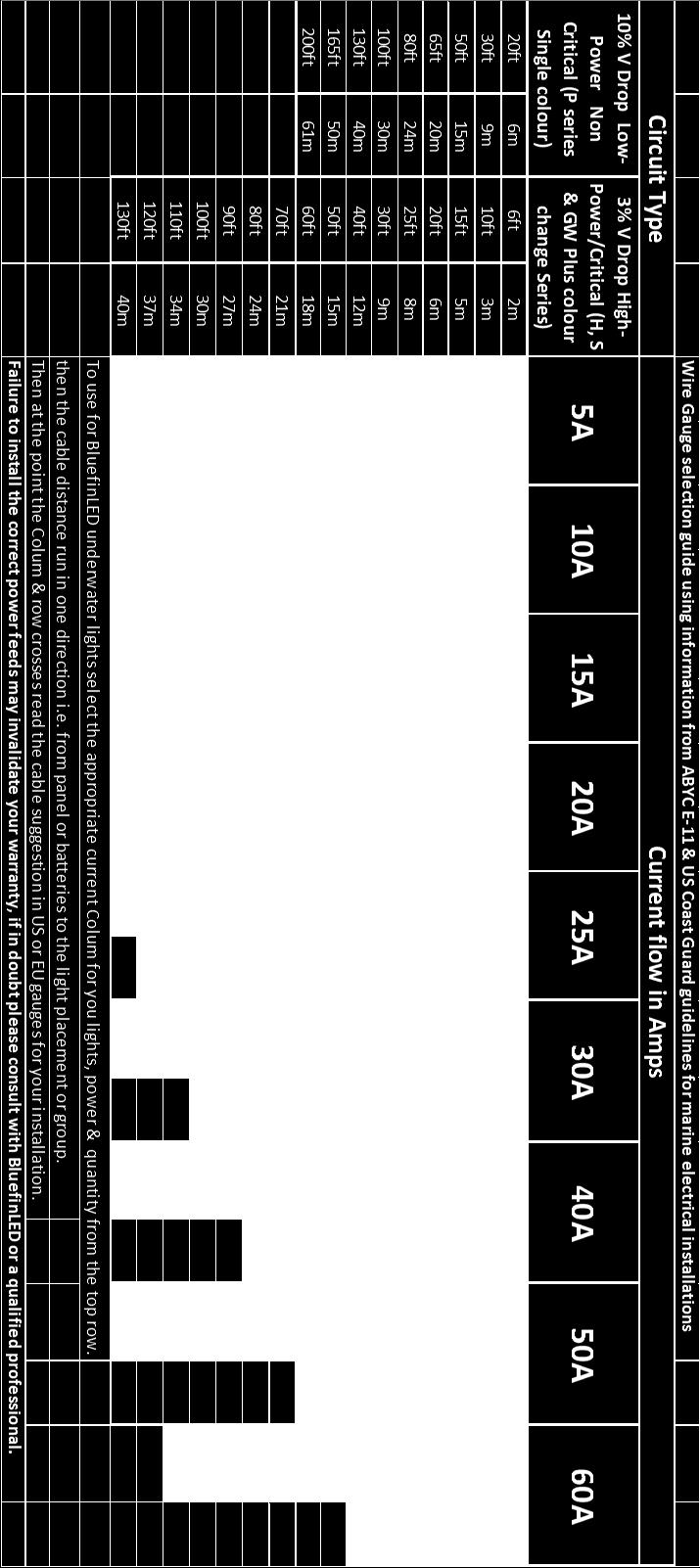
2 Installation: Before installation please ensure the red line is horizontal (the label is fitted to the face of the light), this is to ensure you install the light perpendicular to the water line. Ensure that all lights are fitted the same. If the lights are not all orientated the same way the light will not appear even (different angles) in the water (see fig 6) For optimum affect effect the light should be positioned between 8-12 ( mm) below the water line and at a 90 deg angle. Recommended spacing from 1.65 ft(0.6mtr) to 4.92ft (1.5mtrs) between the lights. Drill a 17mm (17/25 ) hole for the cable access through the hull, ensuring that there are no obstructions internally in the hull. Drill 2.5mm ( 3/32 )pilot holes to match the mounting holes on the light. (Within the packaging there is a mounting template for drilling these holes) Key the area to where the light is to be mounted with abrasive sand paper to ensure there is a clean area for the marine sealant to bond to. Apply marine sealant to the rear of the light on the circumference of the light and around the base of the cable gland to ensure a complete continuous bead of sealant is applied in both areas. (see fig 2) Feed the cable through the hole and mount the light to the hull using the screws provided. Wipe off any excess sealant and ensure the light is seated correctly without any gaps in the sealant. (It is good practice to have excess marine sealant to clean off as this will help assure a water tight seal to the hull) Electrical connection: Ensure you use the IP68 GEL CONNECTOR supplied to connect to the boats wiring or you Warranty will be void (fig 4/5). You will notice an inline moisture guard attached to your cable (Fig 1). If this guard is removed your Warranty will be void. Care should be taken when planning your electrical feeds/cables to the lights so as to ensure voltage drop between the batteries or power supply is minimised, on 12V systems this is especially important as the lower system voltage means a high current requirement which in turn means the potential for more voltage drop in the cable runs & connections. If the cable gauge & connections are not sufficient for the lighting load attached you may experience incorrect operation of the lights & intermittent illumination as the supply dips below specification. Please see the wire gauge guide attached to the instruction manual. For help with calculations always consult with a qualified professional or contact Bluefin LED directly. Attach the light cable to the VDC power on the boat ensuring that you use the GEL CONNECTOR and in line fuse supplied connected to the positive(red) wire, ensure that you use the heat shrink provided to create a water tight fit into the fuse holder. (see fig 3) P24 Dual and CC Colour Only When installing P24 Dual Colour and Colour change lights it is advised to wire the lights up to a single switch so that all of the lights operate in sequence with each other. It is also advised that you choose an appropriate switch that has the correct power rating for the amount of lights being installed (please see the P24 Dual Colour current values above). 2


3 Fig 1 Fig 2 Apply Sealant around this edge and around the cable gland Positive wire from Light Heat shrink for water tight seal to the fuse holder Fig 3 Fig 4 showing how the Gel connector is wired up. Fig 5 showing how the finished Gel connector should look when finished. Ensure that the black outer sheath is inside the gel connector. The IP68 GEL CONNECTOR MUST BE INSTALLED OR YOU WARRANTY WILL BE VOID Fig 4 Power In from boat power Negative wire to boat power Fuse holder Crimps for positive wires (ensure that these are mounted into the holder before they are crimped) Please ensure outer sheath is inside the gel box Light cable Please use fuse instructions within the manual to wire the fuse Heatshrink Image showing how to wire the Gel Connector to the light and Fuse holder 3

4 Fig 5 Testing: Test the light before installation ensuring that you use the correct voltage and the light is illuminated correctly. After installation ensure again that the light is illuminated correctly before the boat goes back into the water and the lens label is removed. After you boat goes back into the water check internally for water ingress around where the light is installed. P24 Dual Colour Operation 1. When first turned on the light will start up in Dual Blue/White mode, if you turn the light off and on again quickly it will then go to Blue mode. If you turn the light off and on again quickly it will then go to White mode. If you turn the light off and on again quickly it will go to Dual Blue/White Strobe mode. If you turn the light off and on again quickly it will strobe on blue. if you turn off and on again quickly it will strobe in white. If you turn off and on again quickly it will strobe alternate blue and white. 2. When the light is turned off for more than 5 secs it will return to standard mode. 3. The light output will adjust itself dependent on the surrounding temperature conditions. P24 Single colour Operation. 1. When powered up for the first time or from reset, the light will appear in the standard on mode. When turned off and on again quickly it will then go to strobe mode. 2. Switch off the light and leave for over 5 seconds, when the light is switched back on the light will reset back in the standard mode. P24CC (Colour change) Operation. 3. When powered up for the first time or from reset, the light will appear in white and scroll through the colour range and keep scrolling until stopped by any of the steps below. 4. To pick a particular colour turn the light off and then on again quickly and the chosen colour will be selected (approx. 1 Sec power cycle, this may take a little practice as too fast or slow will not detect). 5. If you switch off and on again quickly for the second time the light will start to strobe. 6. Switch off the light and leave for over 5 seconds, when the light is switched back on the light will reset back in the white mode. 7. When the light colours become out of sync simply repeat step 4 to re-set to initial colour cycle mode, the more lights installed this process may need to be more frequently repeated. The light has internal indicator LED s for fault finding, these are as follows: Over voltage will flash red.(check the voltage to the light) Under voltage will show a constant red. (check the voltage to the light) Over temperature will show amber.(allow the light to cool down and check if submerged) The light output will adjust itself dependent on the surrounding temperature conditions. 4


5 Fig 6 Ensure Red line is Horizontal to the waterline on all lights. Maintenance: Regularly check the installation for water ingress. Only clean the light with a soft bristle brush. Warranty: Your product has a 2 year limited warranty for defects. For any warranty issues please contact your point of sale retailer or go to for further advice. Installer please ensure that the SERIAL NUMBERS of the lights are written below and the manual is handed over to the end user. Please make a note of the serial numbers of the lights here. SERIAL NUMBERS Bluefin LED Cottage Farm, Cottage Lane, Norton Juxta Twycross, Atherstone. CV9 3QH Sales - Tel: simon.steadman@bluefinled.com Service - Tel: mark.branson@bluefinled.com Administration - Tel: samantha.barrie@bluefinled.com Registered Address: Square Rig Limited, t/a Bluefin Led, Cottage Farm, Cottage Lane, Norton Juxta Twycross, Atherstone, CV9 3QH Company Registration Number: VAT Number:
6 6
Bluefin Led Underwater lights.
 Bluefin Led Underwater lights. P6N/P6CC Installation manual. Thank you for choosing Bluefin LED underwater lights, our products have been designed and tested rigorously to ensure optimum performance and
Bluefin Led Underwater lights.
 Bluefin Led Underwater lights. P3 Installation manual. Thank you for choosing Bluefin LED underwater lights, our products have been designed and tested rigorously to ensure optimum performance and longevity.
Bluefin Led Underwater lights.
 Bluefin Led Underwater lights. V12/V24CC Installation manual. Thank you for choosing Bluefin LED underwater lights, our products have been designed and tested rigorously to ensure the optimum performance
All Bluefin Led lights are water tested so please be aware there may be moisture present on the light.
 Bluefin LED Underwater lights. GW16IFM/GW20IFM/GW48CCIFM Installation manual. Thank you for choosing Bluefin LED underwater lights, our products have been designed and tested to ensure optimum performance
Bluefin Led Underwater lights.
 Bluefin Led Underwater lights. Domestic DL6 Installation manual. Thank you for choosing Bluefin LED underwater lights, our products have been designed and tested rigorously to ensure the optimum performance
Wireless Remote System RC-12v & 24v Standard RF Remote Control System INSTALLATION MANUAL AND OWNERS GUIDE Table of Contents:
 Wireless Remote System RC-12v & 24v Standard RF Remote Control System INSTALLATION MANUAL AND OWNERS GUIDE Table of Contents: Page: 1 Important Safety Instructions/Overview. Pages: 2 Quick Reference Specifications.
Surface Mount e-lites
 Surface Mount e-lites SMX90-CS Colour-SELECT Lights Installation and Operating Guide SMX90-CCP-2 Congratulations! You have purchased a LUMISHORE advanced LED technology underwater lighting system. Every
TIX 402, TIX 802 & TIX 1602 Thru-Hull Light Lumishore SUPRA (dual colour) light Installation and Operating Guide
 light Installation and Operating Guide") SUPRA Thru-Hull Integrated System TIX, TIX & TIX Thru-Hull Light Lumishore SUPRA (dual colour) light Installation and Operating Guide Congratulations! You have purchased a LUMISHORE advanced technology
SUPRA Thru-Hull Integrated System TIX, TIX & TIX Thru-Hull Light Lumishore SUPRA (dual colour) light Installation and Operating Guide Congratulations! You have purchased a LUMISHORE advanced technology
SMX 22, SMX52 & SMX 102 Installation and Operating Guide
 SUPRA Surface Mount Integrated System SMX, SMX5 & SMX Installation and Operating Guide Congratulations! You have purchased a LUMISHORE advanced LED technology underwater lighting system. Every care has
TIX402 EOS Installation and Operating Guide
 TIX402 EOS Integrated System TIX402 EOS Installation and Operating Guide Congratulations! You have purchased a LUMISHORE advanced LED technology underwater lighting system. Every care has been taken to
THX 402, THX 802 & THX 1602 Thru-Hull Light Lumishore SUPRA (dual colour) light Installation and Operating Guide
 light Installation and Operating Guide") SUPRA Thru-Hull Integrated System THX, THX & THX Thru-Hull Light Lumishore SUPRA (dual colour) light Installation and Operating Guide Congratulations! You have purchased a LUMISHORE advanced technology
SUPRA Thru-Hull Integrated System THX, THX & THX Thru-Hull Light Lumishore SUPRA (dual colour) light Installation and Operating Guide Congratulations! You have purchased a LUMISHORE advanced technology
TIX 802 & TIX 1602 Thru-Hull Light Lumishore EOS Full Colour Change light Installation and Operating Guide
 EOS Thru-Hull Integrated System TIX & TIX Thru-Hull Light Lumishore EOS Full Colour Change light Installation and Operating Guide Congratulations! You have purchased a LUMISHORE advanced technology underwater
SMX 92 & SMX 152 Installation and Operating Guide
 EOS Surface Mount Integrated System SMX 92 & SMX 152 Installation and Operating Guide Congratulations! You have purchased a LUMISHORE advanced LED technology underwater lighting system. Every care has
Single Colour Light. TIX202 Interchangeable Flush Fit Thru-Hull Light. Installation and Operation Guide. Rev
 Single Colour Light TIX202 Interchangeable Flush Fit Thru-Hull Light Installation and Operation Guide Rev 3 45-0038 Congratulations! You have purchased a LUMISHORE advanced technology LED underwater light.
Single Colour Light. TIX301 Interchangeable Flush Fit Thru-Hull Light. Installation and Operation Guide
 Single Colour Light TIX301 Interchangeable Flush Fit Thru-Hull Light Installation and Operation Guide Congratulations! You have purchased a LUMISHORE advanced technology LED underwater light. Every care
UltraSystem Series II INSTALLATION MANUAL PARTNERED WITH
 UltraSystem Series II INSTALLATION MANUAL PARTNERED WITH CONTENTS Important information. page 1 Planning the installation. page 2 Transducer positioning. page 3-7 Transducer installation. page 8-10 Control
Your Guide to the Installation, Care and maintenance of PERFORMA. Electronic Self Closing Fittings - Mains Powered 886V (343029) 885V (343027)
 885V (343027)") Your Guide to the Installation, Care and maintenance of PERFORMA Electronic Self Closing Fittings - Mains Powered 886V (343029) 885V (343027) Pegler Limited, St Catherine s Avenue, Doncaster DN4 8DF Telephone
Your Guide to the Installation, Care and maintenance of PERFORMA Electronic Self Closing Fittings - Mains Powered 886V (343029) 885V (343027) Pegler Limited, St Catherine s Avenue, Doncaster DN4 8DF Telephone
THX120-CCP. Colour-CHANGE Lights THX120-CCP Thru-Hull Installation and Operation Guide
 THX120-CCP Colour-CHANGE Lights THX120-CCP Thru-Hull Installation and Operation Guide Congratulations! You have purchased a LUMISHORE advanced technology LED underwater light. Every care has been taken
Neptune X6 12/24V SAE 316L Stainless Steel Low Profile Through-Hull Mounted Underwater LED Light Manual
 Neptune X6 12/24V SAE 316L Stainless Steel Low Profile Through-Hull Mounted Underwater LED Light Manual Thank you for purchasing Dr. LED s Neptune X6 underwater LED light. This 1500+ lumen Neptune X6 underwater
STL Ceptor Series Running Board Light Stick
 2809 Business Park Dr Buda TX 78610 Phone 800.757.2581 Fax 844.894.2652 Email customerservice@speedtechlights.com STL Ceptor Series Running Board Light Stick Operation Manual and Instructions Congratulations,
PIRANHA I & 2 INSTALL GUIDE
 TOP Use 5/32" drill bit DO NOT LET DEADRISE INTERSECT THIS LINE PLACE EITHER CORNER ON DEADRISE ANGLE PIRANHA I & 2 INSTALL GUIDE Two components need to be installed on the boat: the transducer and the
PIRANHA I & 2 INSTALL GUIDE
 PIRANHA I & 2 INSTALL GUIDE Two components need to be installed on the boat: the transducer and the control head. The control head displays sonar information, the transducer sends and receives sonar signals
NON MAINTAINED TWIN SPOTLIGHT WALL MOUNT LED EMERGENCY LIGHT
 Model No. PEL00581 NON MAINTAINED TWIN SPOTLIGHT WALL MOUNT LED EMERGENCY LIGHT 1 Please read these instructions carefully before starting installation and retain for future reference. The centre page
SV10 LED. The US manufactured SV10 LED is. SV10 LED technical specifications
 The US manufactured SV10 LED is the brightest thru hull LED underwater light available to owners of GRP and wood boats. The industry leading SV10 combines the unique qualities of the latest high density
Colour-CHANGE Lights THX72-CCP Thru-Hull and THX72-CCP-FF Flush Fit Installation and Operation Guide
 Colour-CHANGE Lights THX72-CCP Thru-Hull and THX72-CCP-FF Flush Fit Installation and Operation Guide THX72-CCP THX72-CCP-FF Congratulations! You have purchased a LUMISHORE advanced technology LED underwater
CH1900 Series Electronic Control Installation Manual... includes CP1200 Operator Panel MANIN1900 Revision 0
 CH1900 Series Electronic Control Installation Manual... includes CP1200 Operator Panel MANIN1900 Revision 0 CH1900 Series Electronic Control Page 1 Notice to Boat Manufacturer, Installer, and Consumer
Installation Instructions
 Installation Instructions These instructions cover the following kits: 64-66 Mustang Sequential Turn Signal LED kit 67-68 Mustang Sequential Turn Signal LED kit Kit Contents 2 x LED Tail Light Panels 2
PIRANHA 5 INSTALLATION GUIDE
 PIRANHA 5 INSTALLATION GUIDE Two components need to be installed on the boat: the transducer and the control head. The control head displays sonar information, the transducer sends and receives sonar signals
UL Ti MATE Range of underwater lights. (click on document required)
") UL Ti MATE Range of underwater lights (click on document required) Technical UL Ti MATE 75 SA (S.S) UL Ti MATE 75 SA (ALU) UL Ti MATE 75 Fixed (S.S) UL Ti MATE 75 Fixed (ALU) Brochure Info UL Ti MATE 75
UL Ti MATE Range of underwater lights (click on document required) Technical UL Ti MATE 75 SA (S.S) UL Ti MATE 75 SA (ALU) UL Ti MATE 75 Fixed (S.S) UL Ti MATE 75 Fixed (ALU) Brochure Info UL Ti MATE 75
Parkit360 Transformer
 Parkit360 Transformer 1 Owner s Manual Introduction We know you re busy, and need to get that fifth wheel moved. Now. So with that in mind, we ve kept these instructions as brief as possible, but they
ENSURE THAT THE TEMP PROBE FITS YOUR OUTDRIVE BEFORE BEGINNING INSTALLATION.
 715 Center Street Grayslake IL 60030 P: 847-752-2700 F: 847-752-2415 E: info@livorsi.com Drive temp gauge installation instructions Model Number: DCSDT (color) The Livorsi drive temp gauge kit easily installs
Digital Intelligent Battery Charger OPERARATOR S MANUAL
 Digital Intelligent Battery Charger OPERARATOR S MANUAL WARNING! Before you install and use your Nitro Battery Charger, be sure to read and save these safety instructions. INTRODUCTION The Sinergex Nitro
TFL Gas Log Lighter (TFLGLL)
") TFL Gas Log Lighter (TFLGLL) For Jetmaster Metal Fireboxes and Logpans CONTENTS Description Page No. Important information 2 Operation and Design 3 Controller Solenoid Cavity 4 Contents of a Kit 5 To install
TFL Gas Log Lighter (TFLGLL) For Jetmaster Metal Fireboxes and Logpans CONTENTS Description Page No. Important information 2 Operation and Design 3 Controller Solenoid Cavity 4 Contents of a Kit 5 To install
CV41. Vehicle Mounting Kit. Reference Guide
 CV41 Vehicle Mounting Kit Reference Guide CV41 Vehicle Mounting Kit Reference Guide........... 3 Secure the Smart Dock to a Vehicle.................... 3 Supply Power to the Smart Dock......................
STL K-Force 18 and Micro 14 LED Mini Light Bar
 2809 Business Park Dr Buda TX 78610 Phone 800.757.2581 Fax 844.894.2652 Email customerservice@speedtechlights.com STL K-Force 18 and Micro 14 LED Mini Light Bar Operation Manual and Instructions Congratulations,
DC Master 24/ A
 USERS MANUAL DC Master 24/12 50-60A DC-DC converter MASTERVOLT Snijdersbergweg 93, 1105 AN Amsterdam The Netherlands Tel.: +31-20-3422100 Fax.: +31-20-6971006 www.mastervolt.com ENGLISH Copyright 2015
SunLink PV System Disconnect with Arc Fault Detection Installation and Operations Manual
 Combiner Box Installation & Operations Manual SunLink PV System Disconnect with Arc Fault Detection Installation and Operations Manual TABLE OF CONTENTS Notices and Safety Precautions Pages 1-2 Combiner
8-STAGE AUTOMATIC BATTERY CHARGER MCU CONTROLLED - HIGH FREQUENCY SWITCHMODE MODELS: KACHG1207, KACHG1212, KACHG1220, KACHG2410. Instruction Manual
 8-STAGE AUTOMATIC BATTERY CHARGER MCU CONTROLLED - HIGH FREQUENCY SWITCHMODE MODELS: KACHG1207, KACHG1212, KACHG1220, KACHG2410 Instruction Manual Please read user manual carefully before use. WARNING
POWRTOUCH CARAVAN MOVERS REMOTE CONTROL CARAVAN MOVER FAMILY SINGLE AXLE AUTO
 POWRTOUCH CARAVAN MOVERS REMOTE CONTROL CARAVAN MOVER FAMILY SINGLE AXLE AUTO INSTRUCTIONS for the Installation, Operation, Use, Safety & Maintenance of the Powrtouch Evolution Auto IF YOU HAVE PURCHASED
GENUINE PARTS INSTALLATION INSTRUCTIONS
 GENUINE PARTS INSTALLATION INSTRUCTIONS 1. 2. 3. 4. DESCRIPTION: Security Light Kit APPLICATION: Altima Coupe and Sedan (2011+) PART NUMBER: 999F4 AX008 - Universal Security Lighting Kit. KIT CONTENTS:
USER MANUAL LUX-LD30W LED MOVING HEAD
 USER MANUAL LUX-LD30W LED MOVING HEAD LUX-LD30W LED MOVING HEAD For indoor use only Caution! Please read this manual carefully before operating! Damage caused by misuse is not covered by the warranty!
MODEL NUMBER: MEDIUM DUTY ONBOARD AIR SYSTEM
 MODEL NUMBER: 10003 MEDIUM DUTY ONBOARD AIR SYSTEM IMPORTANT: It is essential that you and any other operator of this product read and understand the contents of this manual before installing and using
instructions for roadstart units
 instructions for roadstart units model no: RS1.V5, RS102.V4, RS103.V3 Thank you for purchasing a Sealey product. Manufactured to a high standard, this product will, if used according to these instructions,
SSV2BR INSTRUCTIONS INSTALLATION INSTRUCTIONS
 SSV2BR INSTRUCTIONS INSTALLATION INSTRUCTIONS CONTROLLER MOUNTING: Find a suitable location to mount the control box. Ideally, as with all pool equipment it should be installed out of direct weather and
INSTALLATION I N S T R U C T I O N S
 www.lightmirrors.co.uk Bathroom Cabinet Installation & User Guide Thank you for purchasing our illuminated Cabinets. To avoid product damage or personal injuries, carefully read, understand, and follow
HP10098 BASIC INDEPENDENT AIR SPRING ACTIVATION KIT
 HP10098 BASIC INDEPENDENT AIR SPRING ACTIVATION KIT Thank you and congratulations on the purchase of a Pacbrake basic independent air spring activation kit. Please read the entire installation manual prior
Verti Blast. User Manual. Order code: EQLED355
 Verti Blast User Manual Order code: EQLED355 Safety advice WARNING - FOR YOUR OWN SAFETY, PLEASE READ THIS USER MANUAL CAREFULLY BEFORE YOUR INITIAL START-UP! Before your initial start-up, please make
User Guide for Viridian EV Charging Stations
 User Guide for Viridian EV Stations Iss 3 - JULY 2015 Page 2 of 8 Thank you for purchasing a Viridian EV station. This guide is intended to instruct in the proper use of all models of Viridian stations.
INSTALLATION MANUAL SPECTRUM BRAKE CONTROL
 INSTALLATION MANUAL 51170 SPECTRUM BRAKE CONTROL TABLE OF CONTENTS Controls & Components Tools List Before You Begin Wiring Wiring Diagram Mounting the LED Display Rotary Knob Wiring the Plug Connector
EMF INSTALLATION & OWNER S MANUAL ULTRA COMPACT NICHE LIGHT FOR FIBREGLASS POOLS STORE THIS MANUAL IN A SAFE PLACE FOR FUTURE REFERENCE
 INSTALLATION & OWNER S MANUAL ULTRA COMPACT NICHE LIGHT SPA ELECTRICS PTY LTD w w w. s p a e l e c t r i c s. c o m. a u EMF FOR FIBREGLASS POOLS STORE THIS MANUAL IN A SAFE PLACE FOR FUTURE REFERENCE
O U T B A C K P R O O F G E A R 12V / 24V (MANUAL) O U T B A C K P R O O F G E A R
 O U T B A C K P R O O F G E A R") O U T B A C K P R O O F G E A R 12V / 24V (MANUAL) O U T B A C K P R O O F G E A R Ip68 Waterproof SOLAR BATTERY Mode MODE BUTTON Solar Panel Controller O U T B A C K P R O O F G E A R Ip68 Waterproof
O U T B A C K P R O O F G E A R 12V / 24V (MANUAL) O U T B A C K P R O O F G E A R Ip68 Waterproof SOLAR BATTERY Mode MODE BUTTON Solar Panel Controller O U T B A C K P R O O F G E A R Ip68 Waterproof
UltraSystem Series II INSTALLATION MANUAL
 UltraSystem Series II INSTALLATION MANUAL Manual ref: 02-12-2013 CONTENTS Important information. page 1 Planning the installation. page 2 Transducer positioning. page 3-7 Transducer installation. page
PRODUCT INSTALLATION GUIDE
 PRODUCT INSTALLATION GUIDE MODEL: PRODUCT CODE: PRODUCT DESCRIPTION: 4COMM 4COMMSFK CouplerTec Commercial Heavy Duty Electronic Rustproofing System 12V / 24V Four Capacitive Couplers KIT CONTENTS: ITEM
Service Bulletin No.: DAC Rev 2 Date Issued: Oct 04, 2016 Title: Installation of LED Anti-Collision and Position light Assembly
 Page: 1 of 9 1. ATA Code: 3340 2. Effectivity: DA20-C1 Aircraft S/N C0001 to C0647 3. General: This Service Bulletin addresses the replacement of Whelen s Anti- Collision /Position Light assembly (A600PG-14/A600PR-14)
SP904/3/4/5/7/8/10/11/13 Integrated Wireless Side Warning System
 Fig 1 Operation Guide & Recommended Fitting Instructions. SP904/3/4/5/7/8/10/11/13 Integrated Wireless Side Warning System The SP904 integrated is a fully flexible, easily expandable vehicle blind spot
PIL0478 ISSUE 01/ 07/16
 ISSUE 01/ 07/16 PIL0478 ZAFIR G9 CEILING FITTING PIL0478 ISSUE 01/ 07/16 PART C PART E PART 21 SELV 1 1.B 1 3.1 3.3 3.4 3.5 3.6, 3.8 3.10 3.12 3.14 3.16 3.17 3.18 3.19 3.19 ATTENTION! THE TABLE BELOW
GENUINE PARTS INSTALLATION INSTRUCTIONS
 GENUINE PARTS INSTALLATION INSTRUCTIONS 1. 2. 3. 4. DESCRIPTION: Security Light Kit APPLICATION: Altima Sedan (2013+) PART NUMBER: 999F4 AX010 - Universal Security Lighting Kit. KIT CONTENTS: Item QTY
Automotive: Lightheads
 ENGINEERING COMPANY INC. Winthrop Road Chester, Connecticut 00 Phone: (0) 0 Fax: (0) 07 Internet: www.whelen.com Sales email: autosale@whelen.com Canadian Sales email: canadiansales@whelen.com Customer
Hunter Automatics HA-8. Installation Manual
 Hunter Automatics HA-8 Installation Manual WARNING TO REDUCE RISK OF INJURY 1. READ AND FOLLOW ALL INSTALLATION INSTRUCTIONS CAREFULLY. FAILURE TO DO SO MAY RESULT IN PERSONAL INJURY OR PROPERTY DAMAGE
LCD EWP /FAN DIGITAL CONTROLLER Installation Instructions
 77 Taras Avenue P.O. Box 363 Altona North Vic 3025 Australia Phone: +61(0)3 9369 1234 Fax: +61(0)3 9369 3456 Email: info@daviescraig.com.au Web: www.daviescraig.com.au LCD EWP /FAN DIGITAL CONTROLLER Installation
STL Raptor Series Interior LED Visor Light Bar
 2809 Business Park Dr Buda TX 78610 Phone 800.757.2581 Fax 844.894.2652 Email customerservice@speedtechlights.com STL Raptor Series Interior LED Visor Light Bar Operation Manual and Instructions Congratulations,
Light Source User Guide
 Light Source User Guide Compact Light Source Range Models covered by this manual: UFO 70/150 CG Glass, White Light - 240V UFO 70/150 CP Plastic, White Light - 240V UFO 70/150 CGC Glass, Colour Wheel (continuous)
OceanLED This installation manual covers the following products:
 OceanLED Marine Product Support OceanLED This installation manual covers the following products: PRO SERIES HD Gen2 INSTALLATION MANUAL PRO SERIES HD Gen2 Thru-Hull Thru-Hull Thru-Hull 2010TH HD Gen2 3010TH
Lastolite Lastolite Lumen8 F200 Lumen8 F400 Stored Energy Guide Number (m/100iso) Recycling Time (100%) Flash Duration Flash Power
 Recycling Time (100%) Flash Duration Flash Power") Lastolite Lastolite Lumen8 F200 Lumen8 F400 Stored Energy 200 w/s 400 w/s Guide Number (m/100iso) 42 60 Recycling Time (100%) 0.3 ~ 0.9 sec 0.4 ~ 1.6 sec Flash Duration 1/700 ~ 1/1700 sec 1/700 ~ 1/1700
Lastolite Lastolite Lumen8 F200 Lumen8 F400 Stored Energy 200 w/s 400 w/s Guide Number (m/100iso) 42 60 Recycling Time (100%) 0.3 ~ 0.9 sec 0.4 ~ 1.6 sec Flash Duration 1/700 ~ 1/1700 sec 1/700 ~ 1/1700
AeroVironment Universal Solar Pump Controllers
 AeroVironment Universal Solar Pump Controllers (Installer s business information to be affixed here.) User Manual Models: USPC-2000 (AV Part Number 03747-001 Rev. D) USPC-5000 (AV Part Number 03747-002
START HERE FRONT BUMPER REMOVAL. 1) Turn off engine and chalk tires with stop block. Open Hood. Disconnect Battery.
 Turn off engine and chalk tires with stop block. Open Hood. Disconnect Battery.") BILLET Main Grille Parts included (1) Billet Grille - Main Overlay Polished - Part #6211270 OR Black - Part #6211271 DOES NOT FIT Z71 Models Hardware included (1) #8 x 2.5 (6) #8 x 2 (7) #8 U Nut (7) Bracket
BILLET Main Grille Parts included (1) Billet Grille - Main Overlay Polished - Part #6211270 OR Black - Part #6211271 DOES NOT FIT Z71 Models Hardware included (1) #8 x 2.5 (6) #8 x 2 (7) #8 U Nut (7) Bracket
SECTION M. ELECTRICAL. Section Description Page No.
 SECTION M. ELECTRICAL. Section Description Page No. M.1 General Page 2 M.2 Alternator Page 2 M.3 Battery Page 7 M.4 Hazard Warning System Page 7 M.5 Brake Fail Warning System Page 8 M.6 Seat Belt Warning
Installationn Instruction Manual
 Table of Contents Supplied Kit Parts.Page 2 Required Tool List Page 2 Step by Step Installation Instructions Pages 3-6 Battery Requirements.Page 6 Operation Page 7 Maintenance Page 7 Wiring Diagrams..Page
DMR 3005 WM ONE ZONE WIRELESS DIMMER RECEIVER
 E363518 DMR 3005 WM ONE ZONE WIRELESS DIMMER RECEIVER 20725 NE. 16 AVE. #A-33 MIAMI, FLORIDA 33179 Tel: (305) 652-2599 Fax: (305) 650-8812 www.lumiron.com Email: sales@lumiron.com 1 Benefits and Features
MODUL-CONNECT 1.2. Owner s Manual. Modular, digital wiring and control system. Document Part Number MSMC Rev 9 (04/18)
") MODUL-CONNECT 1.2 Modular, digital wiring and control system Owner s Manual Document Part Number MSMC Rev 9 (04/18) Service Contact Information E-mail: info@modul-system.com Phone: +46 31 746 87 00 Web:
MODUL-CONNECT 1.2 Modular, digital wiring and control system Owner s Manual Document Part Number MSMC Rev 9 (04/18) Service Contact Information E-mail: info@modul-system.com Phone: +46 31 746 87 00 Web:
Hydro-Sync Slide-Out System
 Hydro-Sync Slide-Out System SERVICE MANUAL Rev: 08.14.2018 Hydro-Sync Slide-out System Service Manual TABLE OF CONTENTS Safety Information 3 Product Information 3 Operation 4 Extending Slide-Out Room 4
Fitting Instructions
 Dual Battery Kit Fitting Instructions Fitting Instructions We recommend that the is installed by a licensed auto-electrician. WARNING: Like any addition to your 12v set-up, ensure you ve installed a fuse
Snapshot LX10 USER MANUAL. OK on Dimmer Outdoor OK Sound Activated DMX512 Master/Slave 115V/230V Switch Replaceable Fuse User Serviceable Duty Cycle
 LX10 Snapshot OK on Dimmer Outdoor OK Sound Activated DMX512 Master/Slave 115V/230V Switch Replaceable Fuse User Serviceable Duty Cycle USER MANUAL Chauvet, 3000 N 29 th Ct, Hollywood, FL 33020 U.S.A.
TYPE 4 BEARING INSTALLATION IN COMPOSITE HULLS.
 TYPE 4 BEARING INSTALLATION IN COMPOSITE HULLS. Our tapered Type 4 bearings designed to be installed with our GRP housings These bearings and housings are available in two mounting styles, designed to
LDT Digital Temperature Gauge. Installation & Operation Instructions
 Pub. 988-0099-071 LDT-3200 Digital Temperature Gauge Installation & Operation Instructions The LDT-3200 combines a temperature gauge, voltmeter and clock in one housing. It displays the temperature in
Travel Trekker, 50 Gallon, In-Bed Auxiliary Fuel System* Model
 FOR DIESEL FUEL ONLY TITAN pt. no.: 99 0000 0758 Important: Please read these instructions carefully and completely before starting the installation. TITAN Fuel Tanks INSTALLATION INSTRUCTIONS Travel Trekker,
Installing the gate post bracket with the cardboard arm template
 ......... Installing the gate post bracket with the cardboard arm template... Installing gate posts brackets and arms for Push-to-Open or Pull-to-Open gates... Connection of Power Source 240Vac or Solar...
Compact Triple Electric Step OWNERS MANUAL
 Compact Triple Electric Step OWNERS MANUAL TABLE OF CONTENTS Safety Information 2 Product Information 3 Operation 3 Installation 3 Removal of Existing Step 3 Extending Step Assembly 3 Wiring the Step 4
STL Dart TIR Exterior LED Traffic Advisor Arrow Stick
 2809 Business Park Dr Buda TX 78610 Phone 800.757.2581 Fax 844.894.2652 Email customerservice@speedtechlights.com STL Dart TIR Exterior LED Traffic Advisor Arrow Stick Operation Manual and Instructions
Section II - Installation Procedures Part Number : Accessory Code IL1 Kit Contents. Color Applicability/Trim Level. Hardware Bag Contents
 Document # 10.21.00 PIO/DIO 01/14/09 TOYOTA Rav-4 2009- INTERIOR InteriorLIGHT Light UPGRADE Upgrade Part Number : 00016-00065 Accessory Code IL1 Kit Contents Color Applicability/Trim Level Item # Quantity
HOW - TO WIRING & LIGHTING
 HOW - TO WIRING & LIGHTING Tool And Material Checklist Test Light Service Manual Penetrating Oil Long-Nose Pliers T-Square or Right Angle Screwdriver Black Electrical Tape Fuses Fuse Puller Cloth or Paper
Congratulations on your purchase of your new Ultra-SoniTec Antifouling System! Ultra-SoniTec Antifouling System! Ultra-SoniTec Advanced Ultrasonic
 Congratulations on your purchase of your new Ultra-SoniTec Antifouling System! Ultra-SoniTec Antifouling System! Ultra-SoniTec Advanced Ultrasonic Antifouling Systems are designed algae and other sea growth.
Installation Guide for EcoBrite EndLite LED Light Fixtures
 Installation Guide for EcoBrite EndLite LED Light Fixtures BEFORE YOU BEGIN INSTALLATION Read these instructions carefully. Failure to follow these instructions will invalidate the warranty on this product.
STL Striker /Virtue Interior LED Traffic Series
 2809 Business Park Dr Buda TX 78610 Phone 800.757.2581 Fax 844.894.2652 Email customerservice@speedtechlights.com STL Striker /Virtue Interior LED Traffic Series Operation Manual and Instructions Congratulations,
LED Twister II. User manual UK Version 1.0
 LED Twister II User manual 152.624UK Version 1.0 LED DUOPLEX: For indoor use only CAUTION! Please read this manual carefully before operating! Pay special attention to Sections 3 & 5 of this document.
OceanLED This installation manual covers the following products:
 OceanLED Marine Product Support OceanLED This installation manual covers the following products: PRO SERIES HD Gen2 INSTALLATION MANUAL PRO SERIES HD Gen2 Thru-Hull Thru-Hull Thru-Hull 2010TH HD Gen2 3010TH
OWNERS GUIDE 12V / 24V DC ELECTRIC WINCH. 12,000lb (6124kg) TWO SPEED VERY IMPORTANT
 TWO SPEED VERY IMPORTANT") OWNERS GUIDE 12V / 24V DC ELECTRIC WINCH. 12,000lb (6124kg) TWO SPEED VERY IMPORTANT IT IS ESSENTIAL THAT YOU READ AND UNDERSTAND THIS GUIDE BEFORE INSTALLING AND OPERATING YOUR WINCH WINCHMAX UK WWW.WINCHMAX.CO.UK
OWNERS GUIDE 12V / 24V DC ELECTRIC WINCH. 12,000lb (6124kg) TWO SPEED VERY IMPORTANT IT IS ESSENTIAL THAT YOU READ AND UNDERSTAND THIS GUIDE BEFORE INSTALLING AND OPERATING YOUR WINCH WINCHMAX UK WWW.WINCHMAX.CO.UK
Spectra C3 Light Bar Installation Instructions
 Light Bar Hardware Tools Required Universal Clamp Inserts 1.9, 2 3/8 - OD 5 Amp Fuse 1.25 Hole Saw Philips Screw Driver 7/64 Drill Bit Fish Tape Countersink Pencil Pigtail Wiring Harness Clamp Washer Wire
Measurements are expressed in millimeters.
 T-Rex user manual Measurements are expressed in millimeters. 1 Lamp access 2 Focus adjustment 3 Mounting bracket 4 Swivel locks 5 Clamp hole 6 Air vent 190 285 7 AC input & main fuse 8 Microphone 490 164
U L T I M A T E R A D A R / L A S E R D E F E N S E S Y S T E M
 S m a r t e r Q u i e t e r M o r e A c c u r a t e U L T I M A T E R A D A R / L A S E R D E F E N S E S Y S T E M Installation Manual PASSPORT 9500ci Comes Complete Front Radar Receiver Miniature weatherproof
Go Power! Manual. GP-SW1500 Inverter. Table of Contents. Go Power! Electric Inc. PO Box 6033 Victoria, BC V8P 5L4
 Table of Contents 1. INTRODUCTION... 3 Go Power! Manual GP-SW1500 Inverter 2. SPECIFICATIONS... 3 3. NAME AND MAIN FUNCTION... 3 4. INSTALLATION... 5 5. OPERATION... 7 6. OPERATING LIMITS... 9 7. TROUBLESHOOTING...
Installation Service INSTRUCTIONS
 Installation Service INSTRUCTIONS type 4 rudder bearings Aluminium hull : p2 Composite hull : p3 Instructions for both versions : p4to 13 TYPE 4 BEARING INSTALLATION IN METAL HULLS For a new installation
BEAMER MODEL VDC Spotlight with joystick control panel MODEL VDC Spot/flood light with joystick control panel
 formerly a marinco.com product 502-2 installation & 503-2 instructions 502-2 24 VDC Spotlight with joystick control panel 502-3 24 VDC Spot/flood light with joystick control panel BEAMER MODEL 502-2 24
DriveSync Installation & Operating Instructions
 DriveSync Installation & Operating Instructions Mounting the Device The unit should be mounted in a dry area away from sources of heat. Mounting the unit near the trim pumps will reduce wiring complications.
PH3 AIR INTAKE EMERGENCY SHUT-OFF VALVE WITH POWERGUARD SMART OVERSPEED LIMITER. Generic PH3 Truck Shut-Off Valve Kit.
 PH3 AIR INTAKE EMERGENCY SHUT-OFF VALVE WITH POWERGUARD SMART OVERSPEED LIMITER Generic PH3 Truck Shut-Off Valve Kit www.powerhalt.com INSTALLATION REQUIREMENTS & RECOMMENDATIONS: Prior to the installation,
Exhaust Alert Installation & Operating Instructions THE SCIENCE OF SILENCE. Exhaust Alert Operating & Fitting Instructions 1
 Exhaust Alert Installation & Operating Instructions THE SCIENCE OF SILENCE Exhaust Alert Operating & Fitting Instructions 1 Contents Exhaust Alert Fitting Instructions Section Page 1 Introduction 2 1.1
GLM SERIES CONTROL Users Manual Rev:
 GLM SERIES CONTROL Users Manual Rev: 808062 Connecting Power Page 2 Motor Terminal Wiring Diagrams Page 3 Getting Started / Setup Page 4 1. Obstruction Detection Devices Page 4 2. Checking Power and Direction
POWRWHEEL LIMITED MANUFACTURERS OF THE UK s No 1 REMOTE CONTROL CARAVAN & TRAILER MOVING SYSTEMS TWIN / ALL WHEEL DRIVE MANUAL
 POWRWHEEL LIMITED MANUFACTURERS OF THE UK s No 1 REMOTE CONTROL CARAVAN & TRAILER MOVING SYSTEMS TWIN / ALL WHEEL DRIVE MANUAL INSTRUCTIONS for the Installation, Operation, Use, Safety & Maintenance of
STL Raptor - X TIR Interior LED Visor Light Bar
 2809 Business Park Dr Buda TX 78610 Phone 800.757.2581 Fax 844.894.2652 Email customerservice@speedtechlights.com STL Raptor - X TIR Interior LED Visor Light Bar Operation Manual and Instructions Congratulations,
CONGRATULATIONS ON YOUR PURCHASE OF YOUR THUNDER BATTERY CHARGER! For your personal safety read, understand and follow the information provided in
 CONGRATULATIONS ON YOUR PURCHASE OF YOUR THUNDER BATTERY CHARGER! For your personal safety read, understand and follow the information provided in this instruction manual & on the battery charger. This