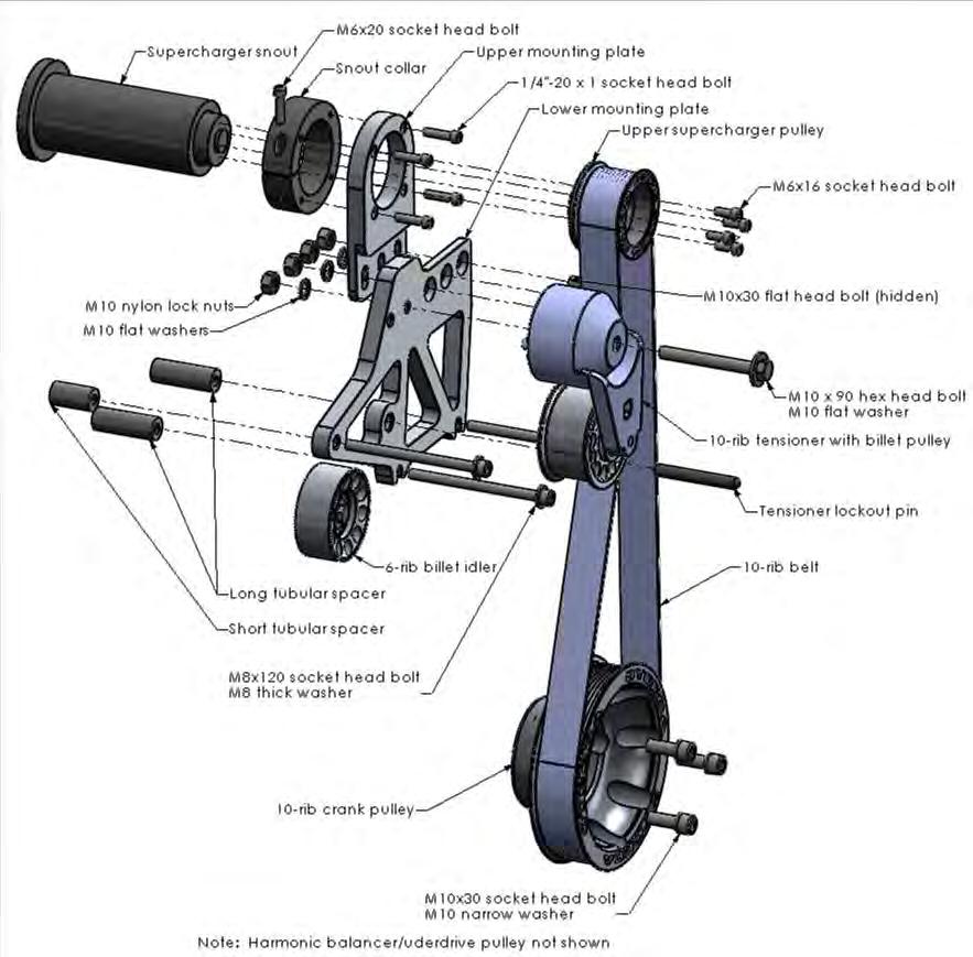
Steeda S197 Mustang Whipple Supercharger Drive
|
|
|
- Charla Wilkerson
- 5 years ago
- Views:
Transcription
1 Steeda S197 Mustang Whipple Supercharger Drive Parts List Qty. Description 1 Whipple supercharger snout 1 Whipple snout collar 1 10-rib supercharger pulley 1 10-rib crank pulley 1 10-rib belt tensioner with billet pulley 1 10-rib belt 1 6-rib accessory drive belt 1 Mounting plate, lower 1 Mounting plate, upper 1 Idler pulley 2 Tubular spacer, long 1 Tubular spacer, short 1 Tensioner locking pin 1 Steeda Underdrive Crank Pulley/Balancer 5 ¼ -20 x 1 Socket head cap screw 1 M12 x 60 Hex Head Bolt 4 M6 x 16 Socket head cap screw 1 M10x90 Hex head bolt 3 M10 x 30 Flat head bolt 4 M10 Nylon lock nut 5 M10 Flat washer 3 M8 x 120 Socket head cap screw 3 M8 thick/hardened flat washers 3 M10 X 30 Socket head cap screw 6 M10 Flat washer, thin 1 M8 X 25 Hex head bolt 1 M8 Fender washer 1 Supercharger base gasket 1 Loctite 518 sealant
2


3 Installation Instructions 1. Disconnect negative battery terminal. 2. Remove strut tower bar, if so equipped. 3. Remove the 2 bolts holding the coolant reservoir to the radiator core support and move the reservoir to the driver s side of the engine compartment De-tension the supercharger/accessory drive belt and remove it. 5. Loosen the hose clamps at the throttle body and MAF sensor. 6. Remove the MAF sensor wire connector. 7. Remove the filter shield/maf pipe assembly. 8. Remove the PCV hose from the intake tube. 9. From the passenger s side, pull the PCV hose out from under the supercharger Remove the intake tube. 11. Remove 2 electrical connectors from the throttle body. 12. Remove 2 bolts and 2 nuts securing throttle body to inlet elbow Remove the 3 vacuum/pcv lines on the inlet elbow. 12


4 14. Remove the intercooler coolant hoses from either side of the manifold Loosen the hose clamp securing the fuel hose to the fuel rail on the driver s side. Remove the fuel hose from the fuel rail. Note: The fuel system may still be pressurized if the vehicle hasn t been sitting a while. Cover the joint with a rag while loosening the clamp and pulling the hose off. 16. From the passenger s side, pull the fuel hose out from under the supercharger. 17. Remove the 10 bolts that secure the supercharger base to the intake manifold. 18. Tilt the front of the supercharger up and lift the whole supercharger/intercooler assembly out of the intake manifold. 19. With the supercharger snout pointing up, remove the 6 bolts holding the snout to the case. 20. Remove the snout. 21. Clean the snout mating surface on the case of any sealant. 22. Apply a thin coating of the supplied anaerobic sealant to the mating surface on the case. 23. Install the new snout and secure with the 6 bolts removed in Step Clean the mating surfaces on the bottom of intercooler and the top of the manifold. 25. Lay the supplied intercooler gasket onto the intake manifold. 26. Drop the supercharger/intercooler assembly into place on the intake manifold being sure that the gasket stays in its proper place. 27. Install the 10 bolts removed in Step Route the fuel hose underneath the supercharger, re-install it onto the driver s side fuel rail, and tighten the hose clamp. 29. Install the intercooler coolant hoses and clamps removed in Step Install the 3 PCV/vacuum hoses removed in Step Install the throttle body with the 2 bolts and 2 nuts removed in Step Install the 2 electrical connectors removed in Step Install the intake tube removed in Step Route the PCV hose that was removed in Step 8 under the supercharger and attach it to the intake tube. 35. Install the filter shield/maf pipe removed in Step 7 and tighten the hose clamps. 36. Install the MAF sensor connector removed in Step 6.

 to the keyway slot on the underdrive crankshaft balancer pulley. Line up the keyway and install the pulley.")

5 37. Remove the passenger s side idler pulley and replace with the supplied billet pulley. The snap ring faces the front of the car, away from the engine. Secure the new pulley with the supplied M8 x 30 bolt and M8 fender washer. 38. From underneath the car, remove the harmonic balancer bolt. An impact wrench will be required for cars with automatic transmissions. Remove the crankshaft balancer/pulley with a three prong puller. 39. Apply a dab of high temperature silicone sealer (gasket maker) to the keyway slot on the underdrive crankshaft balancer pulley. Line up the keyway and install the pulley. Use the longer bolt supplied to pull the balancer onto the crankshaft. DON'T TIGHTEN THE BOLT ALL THE WAY. ONCE THE PULLEY IS ON FAR ENOUGH FOR THE FACTORY BOLT TO REACH, REMOVE THE LONGER BOLT AND INSTALL THE FACTORY BOLT. Torque the factory crankshaft bolt to factory specifications. **Do Not reuse the Factory bolt more than 2 times. If you do, replace it with a new one from your dealership, part # F5RZ-6A340-B. Note: Ford has changed the torque specifications for the crankshaft bolt between 1996 and 2001 even though the Ford Dealer lists the same part number for the bolt. Steeda has found both procedures to work with good result, but suggests you follow Ford's recommendation for your year vehicle Original Ford torque specs: Torque to lb-ft Revised Ford torque specs: Step 1) torque to 66 lb-ft Step 2) loosen bolt 1 full turn Step 3) torque to 37 lb-ft Step 4) tighten bolt an additional 90 degrees. On automatic transmission cars, prevent the engine from turning by holding the torque converter. Access the torque converter by removing a plug towards the front-drivers side of the transmission. (Consult a service manual for more information). Hold the torque converter from turning with a 14mm wrench. 40. Install the 10-rib billet crank pulley onto the harmonic damper face. Secure it with 3 M10 x 30 socket head cap screws and thin washers. Extra washers are included in the event that the end of the bolts contact the timing chain cover.


6 41. Remove the passenger s side Whipple alternator bracket. Re-install the timing chain cover bolt and torque to 37 ft-lbs. 42. Prepare a new alternator bolt by sliding a thick M8 washer onto an M8 x 120 bolt followed by one of the long tubular spacers Install this bolt assembly into the passenger s side alternator mount On the driver s side, remove the Whipple idler pulley and bracket between the alternator and timing chain cover. Re-install the timing chain cover bolt and torque to 37 ft-lbs. 45. Prepare a second bolt as in Step 42 and install it into the driver s side alternator mount. Ensuring that the alternator is pushed all the way to the rear, slide both spacers to the back up against the alternator and the washers forward to the bolt heads.


7 46. Install the supplied 6-rib accessory drive belt in the factory routing configuration. Allow the belt to rest in front of the water pump pulley. 47. Remove the stud on the passenger s side head and relocate the resistor to the front fuel rail bolt. 48. Install the lower mounting plate onto the alternator bolts between the spacer and the washer.


8 49. Position the short tubular spacer between the mounting plate and the timing chain cover and secure with the remaining M8x120 bolt and thick M8 washer. Tighten this bolt and the bolts installed in Steps 42 and 45 to 37 ft-lbs. 50. Finish the accessory belt installation by rotating the tensioner arm clockwise, sliding the belt onto the water pump pulley, and releasing the tensioner arm. 51. Slide the Whipple snout collar over the snout with the rounded edge to the rear and the head of the pinch bolt facing up. Position it so that about ¼ of snout is protruding from the front face. Install 1 ¼ -20 x 1 Socket head cap screw into the pinch bolt recess but do not tighten. 52. Position the upper plate with the top in front of the snout collar and the bottom behind the lower mounting plate. The front faces of the upper plate and lower plate should be in line with each other, not offset. Secure the upper mounting plate to the snout collar with 4 ¼ -20 x 1 socket head bolts and snug the bolts down. 53. Slide the collar/plate assembly forward until the bottom contacts the recess in the lower plate. Secure it to the lower plate with 3 M10x30 flat head bolts, M10 washers, and M10 nylon lock nuts. Tighten to 44 ft-lbs. It is important to hold the bolt still with the Allen wrench while turning the nut rather than turning the bolt.
 which should be done with a 1 /4 - or 3/8 drive torque wrench. 56.")


9 54. Tighten the 4 snout collar bolts installed in Step 52 to 144 INCH-lbs (12 ft-lbs) which should be done with a 1 /4 - or 3/8 drive torque wrench. 55. Tighten the snout collar pinch bolt to 144 INCH-lbs (12 ft-lbs) which should be done with a 1 /4 - or 3/8 drive torque wrench. 56. Install the tensioner with the M10x90 hex head bolt. The pin on the back of the tensioner should fit into the hole in the plate. Tighten the bolt to 44 ft-lbs. 57. Install a flat washer and lock nut to the part of the bolt that protrudes through the back of the plate. 58. Using a ½ drive breaker bar, rotate the tensioner clockwise just until it is possible to slide the tensioner locking pin through one of the holes in the tensioner pulley and the hole in the mounting plate. Insert the pin until it just protrudes from the rear of the plate. This will allow the belt and upper pulley to be installed. Hole Pin


10 59. Install the 10-rib belt around the bottom of the crank pulley. 60. Insert the upper supercharger pulley into the belt. 61. Install the upper pulley onto the supercharger snout and secure with 4 M6x16 bolts. Apply threadlocker before installation. Snug these bolts hand tight. 62. Using a ½ breaker bar, remove the load from the tensioner lockout pin and pull the pin out from the pulley. Slowly release the tensioner against the belt.

11 63. Tighten the pulley bolts installed in Step 61 to 144 INCH-lbs (12 ft-lbs) which should be done with a 1 /4 - or 3/8 drive torque wrench. 64. Slip the coolant reservoir hose back into the driver s side bracket, return the coolant reservoir back to its place, and secure with original bolts. 65. The coolant hose bracket on the driver s side will require manual bending to create clearance for the belt. Simply pull forward on at the bottom hook a little at a time until there is about 34 clearance between the belt and the hose. 66. Install strut tower bar, if so equipped. 67. Re-attach the negative battery terminal and start the car. Check for any coolant leaks and ensure that the belt is running straight in the tensioner pulley. The alignment of the tensioner pulley can be adjusted slightly by loosening the snout collar pinch clamp and moving the collar forward or back. Care must be taken to ensure that the upper mounting plate doesn t contact the back of the upper pulley.
12 Steeda Autosports Inc. All Rights Reserved 2008
Procharger Stage II Intercooled Supercharger System (11-14 GT)
") Procharger Stage II Intercooled Supercharger System (11-14 GT) Installation Time: Approximately one day. Installed on 2012 Mustang GT 5.0/Manual Required Tools 3/8 Socket Set (Standard and Metric) 1/2
Procharger Stage II Intercooled Supercharger System (11-14 GT) Installation Time: Approximately one day. Installed on 2012 Mustang GT 5.0/Manual Required Tools 3/8 Socket Set (Standard and Metric) 1/2
Tork Tech Inc. Customer Service , Sales
 Tork Tech Inc. Customer Service 971.226.9006, Sales 513.697.0060 Email: Info@TorkTech.com www.torktech.com * PREMIUM FUEL MANDATORY * Make sure vehicle has 91+ octane gas in it prior to beginning installation.
BD Venom Dual Fuel F O R D 6. 7 L P O W E R S T R O K E Installation Instructions
 U 30 January 2017 (1050470) Venom Dual Fuel Kit (I-00390) 1 DOWNLOAD ENHANCED INSTALL MANUALS AT dieselperformance.com BD Venom Dual Fuel 2 0 1 1-2 0 1 4 F O R D 6. 7 L P O W E R S T R O K E Installation
ALL AMERICAN BILLET. Front Drive System - Small Block Ford Installation Instructions
 ALL AMERICAN BILLET Front Drive System - Small Block Ford Installation Instructions Small Block Ford with AC & PS All American Billet Store (800) 764-0926 www.allamericanbilletstore.com Items needed for
Fizzle Intercooler Kit Installation Instructions
 Fizzle Intercooler Kit Installation Instructions Note: The minimum exhaust modification required for the installation of this intercooler is the removal of the OEM black plastic resonator box. It can easily
NOTE: Do not disassemble upper intake manifold from lower intake manifold unless replacement of one of the components is necessary.
 Fig. 2: Lower Intake Manifold Bolt Tightening Sequence INTAKE MANIFOLD (UPPER) NOTE: Do not disassemble upper intake manifold from lower intake manifold unless replacement of one of the components is necessary.
Engine Front Cover. Special Tool(s) Lifting Bracket, Engine (2 required) 303-D087 (D93P-6001-A1) or equivalent. Support Bar, Engine 303-F070
 Lifting Bracket, Engine (2 required) 303-D087 (D93P-6001-A1) or equivalent. Support Bar, Engine 303-F070") SECTION 303-01C: Engine 5.4L (4V) 2009 Mustang Workshop Manual IN-VEHICLE REPAIR Procedure revision date: 07/25/2008 Engine Front Cover Special Tool(s) Lifting Bracket, Engine (2 required) 303-D087 (D93P-6001-A1)
SECTION 303-01C: Engine 5.4L (4V) 2009 Mustang Workshop Manual IN-VEHICLE REPAIR Procedure revision date: 07/25/2008 Engine Front Cover Special Tool(s) Lifting Bracket, Engine (2 required) 303-D087 (D93P-6001-A1)
Step 6: Remove and save the MAP sensor for later use. Step 7: Remove the passenger side intercooler pipe and the EGR intake manifold.
 LBZ Twin kit Install Step 1: Disconnect both batteries. Step 2: Drain coolant and oil also remove passenger side inner fender. Step 3: Remove intake box and piping. (Remove and save the MAF sensor in the
BD Venom Dual Fuel F O R D 6. 7 L P O W E R S T R O K E Installation Instructions
 U 21 March 2017 (1050470) Venom Dual Fuel Kit (I-00390) 1 DOWNLOAD ENHANCED INSTALL MANUALS AT dieselperformance.com BD Venom Dual Fuel 2 0 1 1-2 0 1 6 F O R D 6. 7 L P O W E R S T R O K E Installation
2017+ L5P Duramax 3 ½ Down Pipe & EGR Fix Kit
 2017+ L5P Duramax 3 ½ Down Pipe & EGR Fix Kit Covers installation of PN s: WCF100630, WCF100829 Note: This Kit is for off road competition use only! Off Road Competition Use Tuning & Exhaust System is
10-RIB BELT SYSTEM UPGRADE INSTALLATION MANUAL
 10-RIB BELT SYSTEM UPGRADE INSTALLATION MANUAL 2011-2017 AND UP FORD MUSTANG GT 5.0L COYOTE WHIPPLE SUPERCHARGERS 3292 NORTH WEBER AVE FRESNO, CA 93722 TEL 559.442.1261 FAX 559.442.4153 WWW.WHIPPLESUPERCHARGERS.COM
Always wear safety glasses when working on your vehicle.
 90-93 MAZDA MIATA SUPERCHARGER KIT The KraftWerks 90-93 Mazda Miata Supercharger Kit was designed for easy installation. Competent mechanics with the appropriate tools will find the process to be relatively
Instant Chat off the main page of Or simply call our tech team at
 FRONT MOUNT INTERCOOLER 2008-13 STI 2014-04- 08 Thank you for purchasing this PERRIN product for your car! Installation of this product should only be performed by persons experienced with installation
BLACKBIRD INSTALLATION SUPPLEMENT
 BLACKBIRD INSTALLATION SUPPLEMENT FOR 2003-7 FORD 6.0 LITER DIESEL SINGLE ALTERNATOR F-350, F-450, F-550, EXCURSION VERSION 7-07 Parts Description Blackbird Wiring Manual Installation Supplement 6.0 Liter
10-rib belt system upgrade Installation Manual
 10-rib belt system upgrade Installation Manual 2011-2017 and up Ford MUSTANG gt 5.0l coyote WHIPPLE SUPERCHARGERS 3292 NORTH WEBER AVE FRESNO, CA 93722 TEL 559.442.1261 FAX 559.442.4153 A color PDF of
1994 Ford Mustang - Engine Mechanical > Engine Mechanical Components > Timing Chain Cove...
 Page 1 of 6 1994 Ford Mustang : Engine Mechanical > Engine Mechanical Components > Timing Chain Cover & Seal > Removal & Installation > 5.0L Engine 5.0L Engine 1. Disconnect the negative battery cable
Slingshot Rotrex Supercharger Kit
 Slingshot Rotrex Supercharger Kit This supercharger kit improves on the Slingshot by forcing more dense air into the engine and creating more power. Installation time of the supercharger depends on you
2015 Corvette Supercharger System Instructions
 2015 Corvette Supercharger System Instructions These instructions are meant to serve as a guide to the installation of the ECS 2015 Corvette Supercharging system. Please be sure to use all safety equipment
REMOVAL & INSTALLATION
 REMOVAL & INSTALLATION CAUTION: This application is an interference engine. Do not rotate camshaft or crankshaft when timing belt is removed, or engine damage may occur. TIMING BELT CAUTION: DO NOT turn
Installation manual BMW E TS1/TS2
 Installation manual BMW E46 330 TS1/TS2 Technical support Europe: +4741558555 Technical support USA: (858)314-2954 Email support: support@esstuning Installation manual BMW E46 330 TS1/TS2 Remove and send
BLACKBIRD INSTALLATION SUPPLEMENT
 BLACKBIRD INSTALLATION SUPPLEMENT FOR 2008-105 FORD 6.4 LITER DIESEL F-SERIES VERSION 3/10 Parts Blackbird Wiring Manual Installation Supplement 6.4 liter Diesel Owner s Manual Includes Warrantee Registration
CBEA/CJAA Timing belt procedure. Written by: greengeeker Photos by: DanG144, Kriesel, coalminer16. Required tools:
 CBEA/CJAA Timing belt procedure Written by: greengeeker Photos by: DanG144, Kriesel, coalminer16 Required tools: 1. Securing pin 3359 (you need two of them!) 2. Crankshaft stop T10050 3. Counter-hold tool
Complete Holley Mid-Mount Accessory Drive Kit
 Complete Holley Mid-Mount Accessory Drive Kit Part Numbers: 20-181, 20-181BK, 20-181P, 20-182, 20-182BK, 20-182P, 20-191, 20-191BK, 20-191P, 20-192, 20-192BK, 20-192P, 20-201, 20-201BK, 20-201P, 20-202,
CBEA/CJAA Timing belt procedure. Written by: greengeeker Photos by: DanG144, Kriesel, coalminer16. Required tools:
 CBEA/CJAA Timing belt procedure Written by: greengeeker Photos by: DanG144, Kriesel, coalminer16 Required tools: Securing pin 3359 (need two of them!) Crankshaft stop T10050 Counter-hold tool T10172 Special
03-04 Cobra. Hellion Power Systems Mustang Cobra Kit Instructions
 Hellion Power Systems 03-04 Mustang Cobra Kit Instructions NECESSARY PARTS REQUIRED FOR INSTALLATION Necessary: 03-04 Cobra hellion Kit ONLY 99-01 Alternator #YR3210346AA Alternator Bracket #XR3Z-10153-AB
Ford Racing Performance Improvement Intake Manifold (96-04 GT) Time Necessary: Approximately 4 hours
 Time Necessary: Approximately 4 hours") Ford Racing Performance Improvement Intake Manifold (96-04 GT) Time Necessary: Approximately 4 hours Tools Required: Ratchet and socket set Torque wrench Large adjustable wrench Needle nose pliers A dozen
Ford Racing Performance Improvement Intake Manifold (96-04 GT) Time Necessary: Approximately 4 hours Tools Required: Ratchet and socket set Torque wrench Large adjustable wrench Needle nose pliers A dozen
Engine Removal / Installation Sea-Doo 951DI
 Step 1 Battery Removal Step 2 Intake Removal 2.1 (Below) Loosen the two 10mm bolts and slide the intakes out of the brace on the exhaust manifold. Slide the intakes up and out of the hull. 2.3 (Below)
IAG Air / Oil Separator (AOS) For STi
 For STi") IAG Air / Oil Separator (AOS) For 2008-14 STi Part# IAG-ENG-7000 Tools Required: Ratchet, torque wrench, extensions, needle nose pliers, hose cutter, snips/scissors Sockets: 10mm, 12mm 13mm Wrenches: 10mm,
IAG Air / Oil Separator (AOS) For 2008-14 STi Part# IAG-ENG-7000 Tools Required: Ratchet, torque wrench, extensions, needle nose pliers, hose cutter, snips/scissors Sockets: 10mm, 12mm 13mm Wrenches: 10mm,
 Page 1 of 8 2005 Volvo S40 2.4L Eng Base TIMING BELT REPLACEMENT - 2.4L & 2.5L TURBO, 5-CYLINDER REMOVAL & INSTALLATION CAUTION: This application is an interference engine. Do not rotate camshaft or crankshaft
Ford Focus Zetec SVT Timing Belt
 2000-2004 Ford Focus Zetec SVT Timing Belt Replacement This guide will show you how to replace the timing belt on the 2.0L DOHC Zetec with VCT on a 2002 Ford Focus SVT. This is an interference motor. Written
WARNING: ALWAYS relieve fuel pressure before disconnecting any fuel related component. DO NOT allow fuel to contact engine or electrical components.
 4.0L V8 - VINS [K,U] Selected Block 1990 Lexus LS 400 For Lextreme Powertrain 2020 S. Hacienda Blvd. # D Hacienda Heights California 91745 Copyright 1998 Mitchell Repair Information Company, LLC Friday,
SLP Camaro ZL1 STAGE 3 (650 HP)
") SLP - 2012 Camaro ZL1 STAGE 3 (650 HP) PART #26002 PACKING LIST Before installation, use this check list to make sure all necessary parts have been included. ITEM QTY CHECK PART NUMBER DESCRIPTION 1. 1
SLP - 2012 Camaro ZL1 STAGE 3 (650 HP) PART #26002 PACKING LIST Before installation, use this check list to make sure all necessary parts have been included. ITEM QTY CHECK PART NUMBER DESCRIPTION 1. 1
REMOVAL & INSTALLATION
 REMOVAL & INSTALLATION NOTE: For reassembly reference, label all electrical connectors, vacuum hoses and fuel lines before removal. Also place mating marks on engine hood and other major assemblies before
Page 6 of 6 OUTLAW DIESEL EGR COOLER DELETE KIT W/INTAKE ELBOW L FORD POWERSTROKE
 What s in the box 1 Exhaust Block-Off Plate 1 Exhaust Gasket 2 Coolant Line Plugs 1 Brass Barbed Hose Connector 1 Stand-off Spacer 4 M10-1.25 x 40 Hex Head Bolts (Exhaust Manifold) 2 M10-1.25 x 20 Hex
Installation Instructions for: TOYOTA 4.5L SUPERCHARGER SYSTEM
 Installation Instructions for: TOYOTA 4.5L SUPERCHARGER SYSTEM 1995-1997 Land Cruiser * PREMIUM FUEL REQUIRED * Magnuson Products LLC 1990 Knoll Drive, Bldg A, Ventura, CA 93003 (805) 642-8833 phone *
BLACKBIRD INSTALLATION SUPPLEMENT
 BLACKBIRD INSTALLATION SUPPLEMENT 2008 GM 2500 AND 3500 6.6 DURAMAX DIESEL VERSION 5-08 Parts Included in Installation Kit Before beginning installation, check the parts kit thoroughly against the parts
6.4L EGR Delete With Intake Elbow
 6.4L EGR Delete With Intake Elbow J I E C B F D G H A Part# A B C D E F G H I J PACKING LIST: QTY. 2 4 2 4 2 Description Exhaust Block-Off Plate Exhaust Gasket Coolant Line Plugs Brass Barbed Hose Connector
8-Rib Drive Upgrade. Installation Instructions Ford 5.0L Mustang GT P/N: 4FQ , 4FQ , 4FQ SUPERCHARGERS
 8-Rib Drive Upgrade Installation Instructions 2011-2015 Ford 5.0L Mustang GT P/N: 4FQ116-001, 4FQ116-003, 4FQ116-005 SUPERCHARGERS 1650 Pacific Avenue, Channel Islands, CA 93033-9901 Phone: 805 247-0226
IDLER STAND REPLACEMENT MANUAL
 IDLER STAND REPLACEMENT MANUAL 2015 AND UP FORD MUSTANG GT 5.0L COYOTE WHIPPLE SUPERCHARGERS 3292 NORTH WEBER AVE FRESNO, CA 93722 TEL 559.442.1261 FAX 559.442.4153 A color PDF of this manual is available,
INSTALLATION INSTRUCTIONS DUAL OIL CATCH CAN KIT
 INSTALLATION INSTRUCTIONS DUAL OIL CATCH CAN KIT SUBARU WRX FA20F ENGINE Document: 19-0135 Support: info@radiumauto.com This dual catch can kit installs in the right-hand side of the engine bay and intercepts
Timing Chain - Renew ( )
") «Scorpio '95 Table of Contents» «Section 21: Engine» «Subsection 21-05: 2,9 V6 24V Cosworth Engine» «REMOVAL AND INSTALLATION» Timing Chain - Renew (21 314 0) Special Tools 21-140-01Adaptor for 21-140
«Scorpio '95 Table of Contents» «Section 21: Engine» «Subsection 21-05: 2,9 V6 24V Cosworth Engine» «REMOVAL AND INSTALLATION» Timing Chain - Renew (21 314 0) Special Tools 21-140-01Adaptor for 21-140
Porsche 928 with 16v LH-Jetronic Fuel System
 Porsche 928 with 16v LH-Jetronic Fuel System Toll-Free Tech Hot Line: 877-FOR-928M 877-367-9286 Please do not copy this manual and give copies to your friends. Our ability to bring you this supercharger
Chevy Sonic 1.4L Intake Manifold
 Chevy Sonic 1.4L Intake Manifold Install Time: 3 hours In the Box: (1) Racer X Intake manifold (6) M8x1.25 bolts (4) M6x1 bolts (2) 1/8 NPT plugs (1) 3/8 NPT plug (1) 1/4 NPT 90 degree barb (4) Small O-rings
Edelbrock E-Force RPM Carburetor Supercharger C.I.D. Small-Block Chevy
 Edelbrock E-Force RPM Carburetor Supercharger 302-400 C.I.D. Small-Block Chevy 1986 and Earlier Style Heads: 1513, 1514, 15131, 15133, 15141, 15143 E-Tec and Vortec Style Heads: 1515, 1516, 15151, 15153,
v Porsche 928
 1985-86 32v Porsche 928 Toll-Free Tech Hot Line: 877-FOR-928M 877-367-9286 Please do not copy this manual and give copies to your friends. Our ability to bring you this supercharger kit at this price relies
BLACKBIRD INSTALLATION SUPPLEMENT
 BLACKBIRD INSTALLATION SUPPLEMENT FOR 2003-7 FORD 6.0 LITER DIESEL F-SERIES DUAL ALTERNATOR VERSION 10/07 Blackbird Installation Supplement for Ford 6.0. Liter Dual Alternator Parts included in the 6.0
REMOVAL & INSTALLATION
 REMOVAL & INSTALLATION TIMING BELT Removal 1. Noting position for installation reference, disconnect secondary wires from spark plugs. Remove spark plugs. 2. Disconnect negative battery cable. Remove air
Front Drive System - Big Block Chevy Installation Instructions Big Block Chevy with AC & with PS
 Front Drive System - Big Block Chevy Installation Instructions Big Block Chevy with AC & with PS All American Billet Store (800) 764-0926 www.allamericanbilletstore.com Items needed for install Jack Jack
235/245400, , 28N
 Models 235/245400, 287000, 28N thru W, 310/312/313700 These carburetors have a fixed high speed main jet with adjustable idle, Fig 183. The different carburetors are identified as LMT 1 and up. The letters
Complete Holley Mid-Mount Accessory Drive Kit
 Complete Holley Mid-Mount Accessory Drive Kit Part Numbers: 20-180, 20-180BK, 20-180P, 20-185, 20-185BK, 20-185P, 20-190, 20-190BK, 20-190P, 20-200, 20-200BK, and 20-200P 20-200 shown Holley s Mid-Mount
Cylinder Head. Special Tool(s) Compressor, Valve Spring (T93P-6565-AR) Heavy Duty Floor Crane or equivalent
 Compressor, Valve Spring (T93P-6565-AR) Heavy Duty Floor Crane or equivalent") SECTION 303-01C: Engine 5.4L (4V) 2009 Mustang Workshop Manual INSTALLATION Procedure revision date: 04/03/2009 Cylinder Head Special Tool(s) Compressor, Valve Spring 303-452 (T93P-6565-AR) Heavy Duty
SECTION 303-01C: Engine 5.4L (4V) 2009 Mustang Workshop Manual INSTALLATION Procedure revision date: 04/03/2009 Cylinder Head Special Tool(s) Compressor, Valve Spring 303-452 (T93P-6565-AR) Heavy Duty
05-08 GT. Hellion Power Systems Mustang Kit Instructions
 Hellion Power Systems 05-08 Mustang Kit Instructions 1. Disconnect Battery 2. Drain Radiator, keep fluid for re-installation. 3. Remove air box and inlethoses. 6. Next, underneath, punch oil pan for turbo
Timing Chain Renew ( ) Renew. Section Title. Special Tools. Proprietary Tools Scraper Engine support bar
 Renew. Section Title. Special Tools. Proprietary Tools Scraper Engine support bar") Timing Chain Renew ( 34 0) Special Tools 40 400 40 Engine support bar 40 0 Adaptor for -40 40 03 Adaptor for -40 Proprietary Tools Scraper Workshop Equipment Transmission jack Materials Cable ties Sealer
Timing Chain Renew ( 34 0) Special Tools 40 400 40 Engine support bar 40 0 Adaptor for -40 40 03 Adaptor for -40 Proprietary Tools Scraper Workshop Equipment Transmission jack Materials Cable ties Sealer
Edelbrock E-Force Stage II Supercharger CHEVY CORVETTE C7 Z06 LT4 6.2L Part #157320
 2015-16 CHEVY CORVETTE C7 Z06 LT4 6.2L Part #157320 INTRODUCTION Thank you for purchasing the Edelbrock Stage II Supercharger System for the 2015-16 Chevy Corvette Z06 LT4. The Edelbrock E-Force Supercharger
V1 Truck Manifold Turbo Kit for F-body
 V1 Truck Manifold Turbo Kit for 98-02 F-body Prep: -Remove all A/C Components, Alternator and brackets, tensioner, front bumper, front bumper foam, and front bumper support. Remove radiator and cooling
1996 Aerostar/Ranger/Explorer
 Page 1 of 11 Section 03-01B: Engine, 3.0L V-6 IN-VEHICLE SERVICE 1996 Aerostar and Ranger Vehicles Workshop Manual Water Pump SPECIAL SERVICE TOOL(S) REQUIRED Description Tool Number Fan Clutch Holding
Huron Speed Products Twin Turbo Install Gen 2 CTS-V (09-15)
") Huron Speed Products Twin Turbo Install Gen 2 CTS-V (09-15) 1 2 Remove two bolts in trunk cover with 8mm socket. Pull up on cover to remove. Unscrew net tie down on side cover where battery is located
Huron Speed Products Twin Turbo Install Gen 2 CTS-V (09-15) 1 2 Remove two bolts in trunk cover with 8mm socket. Pull up on cover to remove. Unscrew net tie down on side cover where battery is located
IAG Street Series Air / Oil Separator (AOS) For 2017 WRX
 For 2017 WRX") P IAG Street Series Air / Oil Separator (AOS) For 2017 WRX Part# IAG-ENG-7152 Tools Required: Ratchet, torque wrench, extensions, needle nose pliers, hose cutter, snips/scissors, flathead screwdriver,
P IAG Street Series Air / Oil Separator (AOS) For 2017 WRX Part# IAG-ENG-7152 Tools Required: Ratchet, torque wrench, extensions, needle nose pliers, hose cutter, snips/scissors, flathead screwdriver,
INSTALLATION INSTRUCTIONS AIR/OIL SEPARATOR KIT
 INSTALLATION INSTRUCTIONS AIR/OIL SEPARATOR KIT 2015+ SUBARU WRX (LHD ONLY) Document: 19-0136 Support: info@radiumauto.com This document covers the installation of the Radium brake master cylinder brace
 Page 1 of 75 303-01D Engine - 5.2L 32V Ti-VCT 2016 Mustang Assembly Procedure revision date: 12/15/2016 Special Tool(s) / General Equipment Engine Base Part Number: 6L084 205-142 (T80T-4000-J) Installer,
MAZDASPEED3 Intercooler Instructions
 MAZDASPEED3 Intercooler Instructions Congratulations on your purchase of the COBB Tuning Front Mount Intercooler System for your 2007-2009 Mazdaspeed3. The following instructions should assist you through
Engine. Special Tool(s) Compressor, Piston Ring 303-D032 (D81L-6002-C) or equivalent. Compressor, Valve Spring (T93P-6565-AR)
 Compressor, Piston Ring 303-D032 (D81L-6002-C) or equivalent. Compressor, Valve Spring (T93P-6565-AR)") SECTION 303-01C: Engine 5.4L (4V) 2009 Mustang Workshop Manual ASSEMBLY Procedure revision date: 12/12/2008 Engine Special Tool(s) Compressor, Piston Ring 303-D032 (D81L-6002-C) or equivalent Compressor,
SECTION 303-01C: Engine 5.4L (4V) 2009 Mustang Workshop Manual ASSEMBLY Procedure revision date: 12/12/2008 Engine Special Tool(s) Compressor, Piston Ring 303-D032 (D81L-6002-C) or equivalent Compressor,
Installation Manual v1.0: Twin CP3 Fuel Injection Kit Dodge 6.7L
 04/05/2012 Dodge 2010-2011 6.7L Twin CP3 701-900-2356-INST Installation Manual v1.0: Twin CP3 Fuel Injection Kit 2010-2011 Dodge 6.7L Figure 1 - Full Kit Photo 29 Figure 2 - Hardware Kit (800) 949-60002
Engine, disassembling and
 Page 1 of 38 13-1 Engine, disassembling and assembling Lock carrier, moving into service position Special tools and equipment 3369 support tool 1 - Bolts 2 - Bolts 3 - Bolts 4 - Bolts 5 - Bore 45 Nm (33
ALL AMERICAN BILLET. Front Drive System - Small Block Ford Installation Instructions
 ALL AMERICAN BILLET Front Drive System - Small Block Ford Installation Instructions Small Block Ford with AC & PS All American Billet 23042 N 16th Lane Phoenix, AZ 85027 1-844-BILLET1 (844-245-5381) Items
Huron Speed Products Twin Turbo Install Gen 2 CTS-V (09-15)
") Huron Speed Products Twin Turbo Install Gen 2 CTS-V (09-15) The following install guide is simply that, a guide to help you with installation. It is by no means the exact method to perform installation,
Huron Speed Products Twin Turbo Install Gen 2 CTS-V (09-15) The following install guide is simply that, a guide to help you with installation. It is by no means the exact method to perform installation,
8 Zip Tie Zip Tie 1 Union Fitting 1 ½ ½ Union Reducer Fitting Union 1 5/8 ½ (For Plastic Intake Manifold Vehicles)
") P IAG Street Series Air / Oil Separator (AOS) For 2017 STI Part# IAG-ENG-7151 Tools Required: Ratchet, torque wrench, extensions, needle nose pliers, hose cutter, snips/scissors, flat head screw driver,
P IAG Street Series Air / Oil Separator (AOS) For 2017 STI Part# IAG-ENG-7151 Tools Required: Ratchet, torque wrench, extensions, needle nose pliers, hose cutter, snips/scissors, flat head screw driver,
1992 Toyota Cressida
 Monday, May 16, 2016 5:32:47 PM Page 13 2005 Mitchell Repair Information Company, LLC. Fig. 7: Exploded View Of Typical Cylinder Head & Components Fig. 8: Cylinder Head Bolt Removal Sequence Monday, May
EXPANSION TANK PARTS LIST AND INSTALLATION GUIDE
 PARTS LIST AND INSTALLATION GUIDE PARTS LIST 2 PC APPLICATION-SPECIFIC MOUNTING BRACKETS 2 PC BLACK, ANODIZED 6061 ALUMINUM CATCH CANS 4 PC SILICONE HOSES 4 PC PLASTIC BARBED FITTINGS 4 PC WORM-GEAR CLAMPS
INSTALLATION INSTRUCTIONS AOS-R (Air Oil Separator-Return) Turbo Subaru and STi Document# Support:
 Turbo Subaru and STi Document# Support:") INSTALLATION INSTRUCTIONS AOS-R (Air Oil Separator-Return) 02-14 Turbo Subaru and 2015+ STi Document# 19-0102 Support: info@radiumauto.com These instructions are based on a vehicle with an OEM turbocharger
INSTALLATION INSTRUCTIONS AOS-R (Air Oil Separator-Return) 02-14 Turbo Subaru and 2015+ STi Document# 19-0102 Support: info@radiumauto.com These instructions are based on a vehicle with an OEM turbocharger
WARNING: IF YOU ARE NOT EXPERIENCED IN THE AREA OF AUTOMOTIVE MECHANICS WE STRONGLY URGE THAT YOU REFER THIS INSTALLATION TO YOUR MECHANIC.
 INSTALLATION INSTRUCTIONS STILLEN SUPERCHARGER KIT 2003+ Infiniti G35 Materials supplied: See attached list Equipment needed: 1. Assorted sockets and wrenches 2. +,- Screwdrivers 3. Assorted pliers/ Clamps
Front Drive System - Big Block Ford Installation Instructions
 Front Drive System - Big Block Ford Installation Instructions Big Block Ford with AC & with PS All American Billet 23042 N 16th Lane Phoenix, AZ 85027 1-844-BILLET1 (844-245-5381) Items needed for install
REMOVAL 1. DISCONNECT CABLE FROM NEGATIVE BATTERY TERMINAL 2. REMOVE FRONT WHEEL RH. 3. REMOVE REAR WHEEL (for 4WD) (a) Move the select lever to N.
 (a) Move the select lever to N.") REMOVAL 1. DISCONNECT CABLE FROM NEGATIVE BATTERY TERMINAL 2. REMOVE FRONT WHEEL RH 3. REMOVE REAR WHEEL (for 4WD) (a) Move the select lever to N. (b) Check that the parking brake is released. (c) Remove
REMOVAL 1. DISCONNECT CABLE FROM NEGATIVE BATTERY TERMINAL 2. REMOVE FRONT WHEEL RH 3. REMOVE REAR WHEEL (for 4WD) (a) Move the select lever to N. (b) Check that the parking brake is released. (c) Remove
Edelbrock Hemi Supercharger Part #1530, 1531, 1532, 1533, 1536 & 1537
 Edelbrock Hemi Supercharger INTRODUCTION Thank you for purchasing the Edelbrock Hemi Supercharger System for various Chrysler/Dodge vehicles. The Edelbrock E-Force Supercharger System for the 2005 to 2010
Steeda S550 Mustang Street Short Throw Shift Lever Installation Instructions: &
 Steeda S550 Mustang Street Short Throw Shift Lever Installation Instructions: 555-7316 & 555-7322 Tools required 1. 7mm socket 2. 10mm socket 3. Small flathead screwdriver 4. T20 torx bit or driver 5.
DURAMAX LMM EGR DELETE
 007.5-010 DURAMAX LMM EGR DELETE Duramax LMM EGR Delete B K I J F D G H A C PACKING LIST: E Part # A B C D E F G H I J K QTY. 1 1 1 1 Description Billet Intake Block Off Plate with O-ring Exhaust Block
IAG Street Series Air / Oil Separator (AOS) For WRX
 For WRX") P IAG Street Series Air / Oil Separator (AOS) For 2015-16 WRX Part# IAG-ENG-7152 Tools Required: Ratchet, torque wrench, extensions, needle nose pliers, hose cutter, snips/scissors, flat head screw driver,
P IAG Street Series Air / Oil Separator (AOS) For 2015-16 WRX Part# IAG-ENG-7152 Tools Required: Ratchet, torque wrench, extensions, needle nose pliers, hose cutter, snips/scissors, flat head screw driver,
TIMING BELT COMPONENTS EM 15
 ENGINE MECHANICAL COMPONENTS EM15 EM16 ENGINE MECHANICAL COMPONENTS (Cont d) ENGINE MECHANICAL EM17 REMOVAL OF (See pages EM15 and 16) 1. DISCONNECT CABLE FROM NEGATIVE TERMINAL OF BATTERY CAUTION: Work
Service and Repair. a. Remove the 2 nuts and 2 upper radiator support. b. Lift out the radiator and cooling fan assembly.
 Service and Repair REPLACEMENT 1. SEPARATE BATTERY NEGATIVE TERMINAL 2. REMOVE AIR CLEANER INLET NO.1 3. DRAIN ENGINE COOLANT 4. REMOVE V-BANK COVER 5. REMOVE INTAKE AIR CONNECTOR PIPE 6. REMOVE ENGINE
ALLDATA Online Ford Focus L4-2.0L DOHC VIN 5 - Service and Repair. Service and Repair
 Page 1 of 22 Service and Repair NOTE: Ford does not provide camshaft gear timing marks, or information to perform timing belt service without the special tools shown in this procedure. Timing Belt Special
1989 Nissan 300ZX. 3.0L V6 - VIN [H] & 3.0L V6 TURBO - VIN [C] 1989 Engines - 3.0L & 3.0L Turbo V6
![1989 Nissan 300ZX. 3.0L V6 - VIN [H] & 3.0L V6 TURBO - VIN [C] 1989 Engines - 3.0L & 3.0L Turbo V6](/thumbs/95/124411779.jpg "1989 Nissan 300ZX. 3.0L V6 - VIN [H] & 3.0L V6 TURBO - VIN [C] 1989 Engines - 3.0L & 3.0L Turbo V6") INTAKE MANIFOLD Removal 1. Release fuel system pressure. Disconnect battery and drain cooling system. Disconnect vacuum and coolant lines attached to intake manifold and label accordingly. Remove throttle
INTAKE MANIFOLD Removal 1. Release fuel system pressure. Disconnect battery and drain cooling system. Disconnect vacuum and coolant lines attached to intake manifold and label accordingly. Remove throttle
Phone Fax
 Directions for Installation of ECS Paxton Supercharger Kit Disconnect battery Remove stock serpentine belt Remove stock belt tensioner, save the 2 bolts for later use on supercharger bracket Remove alternator
INSTALLATION INSTRUCTIONS STILLEN SUPERCHARGER KIT Nissan 350Z P/N &
 Equipment needed: 1. Assorted sockets and wrenches 2. +,- Screwdrivers 3. Assorted pliers/ Clamps 4. Wire cutting/crimping tools 5. Thread locking compound (blue) 6. Solder gun/ shrink wrap (optional)
C63 Weistec M156 Supercharger System Installation Guide Stage 3
 C63 Weistec M156 Supercharger System Installation Guide Stage 3 WARNING! DO NOT HAVE YOUR ECU REPROGRAMMED ANYWHERE BUT AT WEISTEC FOR THIS SUPERCHARGER. THE AMG 63 USES AN ELECTRONIC THROTTLE CONTROL
Wrenches: ⅞, 8mm, 10mm, 13mm, 19mm P. allen, Other: Electrical Tape
 IAG Street Series Air / Oil Separator (AOS) For 2008-14 STI Part# IAG-ENG-7100 Tools Required: Ratchet, torque wrench, extensions, needle nose pliers, hose cutter, snips/scissors, flat head screw driver,
Audi S1 Intake kit. Qty. Description
 Audi S1 Intake kit Description Qty Silicone Intake pipe 1 Vacuum hose 1 Heatshield 1 Bracket 1 Machined inlet 1 Vacuum connector 1 Filter 1 M6x16 cap head bolt 1 Tools Ratchet Extension Torx socket Sockets
Tools Required. Metric Wrench Set Screwdriver Set Metric Socket Set Pliers Heavy duty hydraulic Jack and Car Stands Box knife or similar Hacksaw WD40
 Subaru 2004+ Legacy GT & Outback XT For JDM 2.0 twinscroll turbo and USDM 2.5 turbo models Front Mount Intercooler Fitting Instructions PN# LEG-1348-000 You are now the proud owner of a highly tested and
2001 Ford FOCUS. Submodel: ZTS Engine Type: L4 Liters: 2.0 Fuel Delivery: FI Fuel: GAS. Timing Belt
 2001 Ford FOCUS Submodel: ZTS Engine Type: L4 Liters: 2.0 Fuel Delivery: FI Fuel: GAS SECTION 303-01A: Engine??? 2.0L Zetec-E (Zetec) 2001 Focus Workshop Manual IN-VEHICLE REPAIR Procedure revision date:
This information covers the proper procedure for replacing the Volvo D16F engine in a VT or VNL chassis.
 Volvo Trucks North America Greensboro, NC USA Engine, Replacement DService Bulletin Trucks Date Group No. Page 10.2007 210 139 1(47) Engine, Replacement Volvo D16F VNL, VT W2005773 This information covers
Edelbrock E-Force Supercharger Part #1538: Dodge 1500 Truck 5.7L V8 HEMI
 Edelbrock E-Force Supercharger Part #1538: 2009-2014 Dodge 1500 Truck 5.7L V8 HEMI 2009-14 Dodge 5.7L Hemi 1500 Truck INTRODUCTION Thank you for purchasing the Edelbrock Supercharger System for the 2009-15
Edelbrock 5.4L F-150 Supercharger Part #1583
 Edelbrock 5.4L F-150 Supercharger INTRODUCTION Edelbrock 5.4L Ford Supercharger System Thank you for purchasing the Edelbrock 5.4L Ford Supercharger System for the F-150. The Edelbrock E-Force Supercharger
Keeping You Cool Under Pressure
 Installation Instruction for 92-93 GM 6.5L Turbo Diesel Series 3500-4 Wheel Drive Pickup and Series 1500, 2500, 3500 4 Wheel Drive Suburban Intercooler System (Part No. 2-436) TOOLS REQUIRED: 1.) Normal
INSTALLATION INSTRUCTIONS AOS-R (Air Oil Separator-Return) Turbo Subaru and STi Document# Support:
 Turbo Subaru and STi Document# Support:") INSTALLATION INSTRUCTIONS AOS-R (Air Oil Separator-Return) 02-14 Turbo Subaru and 2015+ STi Document# 19-0102 Support: info@radiumauto.com These instructions are based on a vehicle with an OEM turbocharger
INSTALLATION INSTRUCTIONS AOS-R (Air Oil Separator-Return) 02-14 Turbo Subaru and 2015+ STi Document# 19-0102 Support: info@radiumauto.com These instructions are based on a vehicle with an OEM turbocharger
Models Affected: Visions with Propane Engines CORRECTIVE ACTION ---- PROCEDURE
 Propane Belt Squeal Models Affected: Visions with Propane Engines ISSUE Front End Accessory Drive (FEAD) Belt chirping/squealing caused by improper fore-aft crankshaft pulley positioning. CORRECTIVE ACTION
IAG Competition Series Air / Oil Separator (AOS) For 2017 STI
 For 2017 STI") P IAG Competition Series Air / Oil Separator (AOS) For 2017 STI Part# IAG-ENG-7251 Tools Required: Ratchet, torque wrench, extensions, needle nose pliers, hose cutter, snips/scissors, flat head screw driver,
P IAG Competition Series Air / Oil Separator (AOS) For 2017 STI Part# IAG-ENG-7251 Tools Required: Ratchet, torque wrench, extensions, needle nose pliers, hose cutter, snips/scissors, flat head screw driver,
INSTALLATION INSTRUCTIONS Dual Catch Can Kit Subaru Turbo and STi Document# Support:
 INSTALLATION INSTRUCTIONS Dual Catch Can Kit 02-14 Subaru Turbo and 2015+ STi Document# 19-0099 Support: info@radiumauto.com This document covers the installation of a Radium dual catch can kit for the
928 Motorsports Supercharger Installation Copyright 2007, 928 Motorsports, LLC All Rights Reserved
 For Porsche 928 equipped with K-Jetronic (CIS) Fuel System Toll-Free Tech Hot Line: 877-FOR-928M 877-367-9286 Please do not copy this manual and give copies to your friends. Our ability to bring you this
Steeda Billet Charge Motion Control Plates (05-08 GT) - Installation Instructions
 - Installation Instructions") Steeda Billet Charge Motion Control Plates (05-08 GT) - Installation Instructions The below installation instructions work for the following products: Steeda Billet Charge Motion Control Plates (05-08
Steeda Billet Charge Motion Control Plates (05-08 GT) - Installation Instructions The below installation instructions work for the following products: Steeda Billet Charge Motion Control Plates (05-08
These instructions were written for reference only and the use of a factory service manual is recommended.
 Introducing the CorkSport High Pressure Fuel Line designed for the MZR DISI. This fuel line is designed to replace the OEM fuel line which are prone to failure at the brazed connection at the rail. The
1991 Volkswagen Vanagon Syncro
 corner of radiator. See Fig. 1. Fig. 1: Bleeding Cooling System 2. Open bleeder valve in engine compartment (turn counterclockwise). See Fig. 1. Fill expansion tank until full. Start and run engine at