Operator and Parts Manual
|
|
|
- Laureen Summers
- 5 years ago
- Views:
Transcription
1 Operator and Parts Manual Backsaver Auger 10" Model FK306 Rev 6
2
3 Table of Contents - 10" Backsaver Auger Table of Contents Introduction...5 Safety...6 Safety...6 General Safety...7 Start-up Safety...7 Operation Safety...7 Transport Safety...8 Service and Maintenance Safety...8 Storage Safety...9 Safety Signs...9 Safety Sign Installation...9 Assembly...12 Assembly Instructions...12 Operation...13 Theory of Operation...17 Maintenance...18 Maintenance and Lubricants...18 Storage...18 Greasing Procedure...19 Bolt Torque...20 Checking Bolt Torque...20 Parts Drawings...22 Auger Assembly Drawing...22 Auger Assembly Parts List...23 Lift Boom Arm Components Drawing...26 Lift Boom Arm Components Parts List...27 Undercarriage Components Drawing...28 Undercarriage Components Parts List...29 Hopper and Auger Assembly Drawing...32 Hopper and Auger Assembly Drawing...33 Input Box Assembly Drawing...34 Input Box Assembly Parts List...35 Intake Auger Drawing...38 Intake Auger Parts List
4 Table of Contents - 10" Backsaver Auger Single-flighting Hopper Drawing...40 Single-flighting Hopper Parts List " x 10' Extension Drawing " x 10' Extension Parts List...43 Multi-flighting Hopper Drawing...44 Multi-flighting Hopper Parts List...45 Cables Drawing...48 Cables Parts List...49 Idler Assembly Drawing...50 Idler Assembly Parts List...51 Tire Assembly Drawing...52 Tire Assembly Parts List...53 Cylinder Mount Components Drawing...54 Cylinder Mount Components Parts List Dia. x Cylinder Drawing and Parts List Dia. x Cylinder Drawing and Parts List Dia. x Cylinder Drawing and Parts List...58 PTO Shaft Drawing...60 PTO Shaft Parts List...61 Mechanical Drive - Input Box Gearbox Drawing...62 Mechanical Drive - Input Box Gearbox Parts List...63 Mechanical Drive - Intake Auger Gearbox Drawing...64 Mechanical Drive - Intake Auger Gearbox Parts List Winch Drawing Winch Parts List...67 Shipping Kit and Bundle Numbers...68 Warranty...76 Manufacturer s statement: for technical reasons Buhler Industries Inc. reserves the right to modify machinery design and specifications provided herein without any preliminary notice. Information provided herein is of descriptive nature. Performance quality may depend on soil fertility, applied agricultural techniques, weather conditions and other factors. 4
5 Introduction - 10" Backsaver Auger Introduction Farm King gives you more choices to match your auger to your bins, power sources and operating convenience. The superior scissor lift system features a one way hydraulic cylinder with a restrictor valve to control the rate of descent in the event of hydraulic hose failure. This feature is safer than conventional cable systems. Also, note the extra wide undercarriage and wheel tread providing better stability at greater heights, particularly in windy conditions. The unique mechanical linkage is designed to use less hydraulic pressure to lift the auger, even when fully loaded. The pivoting Hopper Lift Arm may be flipped over for left or right transport position. Slip the PTO from the main shaft onto the optional reverse kit for complete cleanout. An adjustable arm holds the PTO shaft when not in use. The hitch is adjustable for various tractor hitch lengths. The shut off valve is designed to keep your auger in the position you set it. The cross auger is driven by two internal gearboxes. These assemblies are easily reached for service. Because of the large input and intake boxes, capacity is not restricted. The standard self leveling hopper on all Backsaver Augers stays flat on the ground, even when the auger is raised up to a high bin. The optional double auger hopper is 2.5" (63.5mm) lower than the standard self-leveling hopper and has a hinged cover for easy servicing. An optional 2-wheel power mover allows you to move the hopper back and forth with fingertip control. Other advanced features include a tapered thrust bearing at the top of the auger, torqued to remove pressure on the bottom end bearing. Keep this manual handy for frequent reference. All new operators or owners must review the manual before using the equipment and at least annually thereafter. Contact your Farm King Dealer if you need assistance, information, or additional copies of the manual. Visit our website at for a complete list of dealers in your area. The directions left, right, front and rear, as mentioned throughout this manual, are as seen facing in the direction of travel of the implement. 5
6 Safety - 10" Backsaver Auger Safety Safety Instructions Remember, YOU are the key to safety. Good safety practices not only protect you, but also the people around you. Make these practices a working part of your safety program. Be certain that everyone operating this equipment is familiar with the recommended operating and maintenance procedures and follows all the safety precautions. Most accidents can be prevented. Do not risk injury or death by ignoring good safety practices. The alert symbol is used throughout this manual. It indicates attention is required and identifies hazards. Follow the recommended precautions. The safety alert symbol means ATTENTION! BECOME ALERT! YOUR SAFETY IS INVOLVED! Caution Warning Danger The caution symbol indicates a potentially hazardous situation that, if not avoided, may result in minor or moderate injury. It may also be used to alert against unsafe practices. The Warning Symbol indicates a potentially hazardous situation that, if not avoided, could result in death or serious injury, and includes hazards that are exposed when guards are removed. It may also be used to alert against unsafe practices. The Danger Symbol indicates an imminently hazardous situation that, if not avoided will result in death or serious injury. This signal word is to be limited to the most extreme situations, typically for machine components that, for functional purposes, cannot be guarded. 6
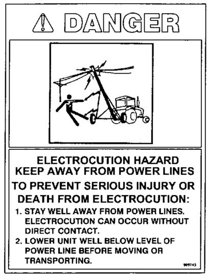
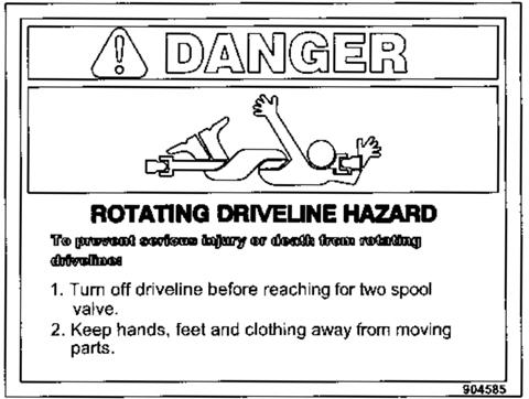
7 Safety - 10" Backsaver Auger General Safety Instructions Have a first-aid kit available for use and know how to use it. Have a fire extinguisher available, stored in a highly visible location, and know how to use it. Wear appropriate protective gear. This list may include but is not limited to: -- hard hat -- protective shoes with slip resistant soles -- protective glasses or goggles -- heavy gloves -- wet weather gear -- hearing protection -- respirator or filter mask Read and understand the Operator s Manual and all safety signs before operating, servicing, adjusting, repairing, or unplugging the equipment. Do not attempt any unauthorized modifications to your Farm King product as this could affect function or safety, and could affect the life of the equipment. Never start or operate the mower except from the operator s station on the power unit. Inspect and clean the working area before operating. Keep hands, feet, clothing, and hair away from moving parts. Ensure bystanders are clear of the area before operating. Start-up Safety Do not let inexperienced operators or children run this equipment. Place all tractor and machine controls in neutral before starting. Operate only with ROPS and seatbelt equipped tractors. Do not operate inside a building unless there is adequate ventilation. Ensure all shields are in place and in good condition before operating. Stay clear of PTO shaft and machine when engaging PTO. The Auger must be on a level surface and wheels free to move when raising or lowering. Everyone should be kept clear during these operations. Operation Safety Do not permit riders. Do not wear loose fitting clothing during operation. Empty the Auger before moving to prevent upending. The Backsaver Auger should be attached to the drawbar of the tractor at all times during operations. Do not allow anyone other than the operator close to the Auger when in operation. Never stand under the auger while raising or lowering. When filling tall bins, tanks, or granaries, it is advisable to anchor the auger to the bin or building to prevent it from being tipped over by the wind or a sudden movement. Do not operate Intake Auger when it is folded in transport position. Stay away from overhead obstructions and power lines during operation and transporting. Electrocution can occur without direct contact. 7
8 Safety - 10" Backsaver Auger Transport Safety Review Transport Safety instructions in tractor manual before moving. Check with local authorities regarding transport on public roads. Obey all applicable laws and regulations. Do not tow equipment that does not have brakes at speeds over 20 mph/h (32 km/h). Do not tow equipment that does not have brakes that, when fully loaded, has a mass (weight) over 3300 lb (1.5 t) and more than 1.5 times the mass (weight) of the towing unit. Make sure the SMV (Slow Moving Vehicle) emblem and all the lights and reflectors that are required by the local highway and transport authorities are in place, are clean, and can be seen clearly by all overtaking and oncoming traffic. Always transport the Backsaver Auger in the down position, carrying the weight of the Auger on the undercarriage itself, and not the hydraulic cylinder. Take extreme caution in maneuvering on or around tight corners so as not to catch the end of the auger on trees, buildings, power lines, etc. The equipment should never be towed without the safety chain securely attached to the Auger and the towing vehicle. When moving the Auger on the road, always use a red flag, or if absolutely necessary to move at night, accessory lights for adequate warning to operators of other vehicles. Always travel at a safe speed. Inflate transport tires to recommended pressure. Service and Maintenance Safety Stop engine, set brake, remove ignition key, and wait for all moving parts to stop before servicing, adjusting, repairing, or unplugging. Support the equipment with blocks or safety stands before working beneath it. Follow good shop practices including: -- keep service area clean and dry -- be sure electrical outlets and tools are properly grounded -- use adequate light for the job. Use only tools, jacks, and hoists of sufficient capacity for the job. Replace and secure all shields removed during servicing before operating. Use heavy leather gloves to handle sharp objects. Check hydraulics regularly for leaks. Use cardboard to look for leaks, and use hand and eye protection. Relieve pressure on hydraulic system before repairing or adjusting. Failure to follow proper procedures when mounting a tire on a wheel or rim can produce an explosion, which may result in serious injury or death. 8
9 Safety - 10" Backsaver Auger Storage Safety Store the unit in an area away from human activity. Do not permit children to play on or around the stored machine. Support the frame on stands and blocks to provide a secure base. When storing an Auger, park it on level ground so that the bottom end will never be over its center of gravity. Block the wheels of the Auger so that it will not move and tear the jack from it s mount. Safety Signs The following illustration shows the approximate location and detail of safety signs. Keep all safety signs clean and legible and replace any that are damaged or missing. When original parts are replaced, any safety signs affixed to those parts should be replaced as well. Replacement safety signs are available from your local dealer. Installation To install safety signs, ensure the installation area is clean and dry. Decide on the exact position before you remove the backing paper. Remove the smallest portion of the split backing paper and align over the specified area. Carefully press in place. Slowly peel back the remaining paper and smooth the remaining portion in place. Small air pockets can be pierced with a pin and smoothed out. 9


10 Safety - 10" Backsaver Auger Replace safety signs immediately should they become damaged, torn or illegible. Obtain replacements from your authorized dealer using the part numbers shown


11 Safety - 10" Backsaver Auger
12 Assembly - 10" Backsaver Auger Assembly Instructions Alert There are two holes on the top stub shaft for cotter pin installation on the top flighting, which should allow a wide range of adjustment. If the top flighting is too high, there could be a shortage of room to mount the bottom bearing in the input box. Alert On the bridging yokes where the cable clamps hold two cables, do not use the cast part of the cable clamp or it will be very difficult to get the nuts on the clamps. Use 3/8" I.D. flat washers on cable clamps. Alert The arches are left and right. The bracket for attaching the brace (#80) is turned to the outside. Ends of brace bent at 30 are bolted to the arch. The other end bolts to the undercarriage. Alert The welded cross brace on the pivot yoke should be facing the input box end of the auger. Alert The flow control valve regulates the lowering of the auger to avoid damage which could be caused by lowering the auger too quickly. Arrow should be pointing away from cylinder. Be sure that valve is open approximately 3 1/2 turns before raising to full position or auger will not lower. Alert If the intake auger is removed for repair or replacement, the bolt coupling the flighting to the intake auger gearbox must be replaced when the flighting is replaced. Failure to do so could cause failure of the hopper flighting. 12
13 Operation - 10" Backsaver Auger Operation Instructions All augers may be elevated up to 45 ; however, for the best operating efficiency, 35 should not be exceeded. At angles over 35 the capacity and life of the auger decreases. Use in some types of fertilizer may cause accelerated wear and corrosion as well as added stress on lift components due to additional load. Use in fertilizer can affect warranty. Run auger partially full until flighting becomes polished. Never operate an empty auger for over one minute, as the flighting and housing will experience excessive wear. To position the auger, always tow or move the auger in the down position to a point as close as possible to the bin or barn. Alert Always keep the wheels level. Raise the auger to the desired height and back the auger into position. Do not support the auger on the bin. As the auger becomes full it carries alot of weight and may cause damage to the underside of the auger to the bin. Alert The auger should be firmly attached to the drawbar of the tractor at all times during operation. Alert Never place blocks under the wheels to increase the elevation of auger. Be sure the wheels are free to move and no one is standing close to the auger when raising or lowering. Never attempt to raise or lower the auger while it is in operation. Alert Be sure winch brake is working properly before transporting. An arrow on the winch shows the proper direction of rotation. Improper rotation may cause winch failure. Never have less than three wraps of cable on the drum of the winch. The intake auger swivels freely on the top of the input box. It can be positioned anywhere between the tractor and the side of the auger. CAUTION 10" augers are destined for PTO drive tractors with 540 PTO rpm only. Maximum capacity will be attained while running the main auger between PTO rpm. (Do not use 1000 PTO rpm speed on these augers) 13
14 Operation - 10" Backsaver Auger ALERT Always maintain at least a 4" over lap on the PTO guards. Be sure they turn freely and make certain everyone stands clear of tractor, PTO shaft, and auger before engaging PTO. Be sure ends are securely connected to the auger and tractor. An optional shaft is offered for extreme use. The distance between the tractor and the auger stubs should be between 36" and 38" with the tractor and auger on level ground and the auger in full down position. This distance is obtained by either adjusting the tractor hitch, the auger hitch or both. Before engaging PTO, start tractor and idle engine. Engage PTO slowly and bring up to recommended speed of 500 PTO rpm for 10" augers. Before stopping auger (except in an emergency) let all grain empty out of the auger, idle engine then disengage PTO. Shut off tractor. Alert Do not use the reverse kit to attempt to unplug the auger. The reverse kit is designed to be used for CLEAN-OUT ONLY! Alert When auger is left in raised position over night, close the ball valve on the hydraulic line to the cylinder. This will prevent the auger from lowering, due to hydraulic leakage, and avoid possible damage. One-way flow control valve (#115) can be adjusted by loosening the hex nut on the side, and turning on the screw with the machined end. Turning the screw in decreases the speed the auger lowers, while turning it out increases the speed. The approximate initial setting should be three turns out from the tight position. When set, re-tighten hex nut to set position. 14
15 Operation - 10" Backsaver Auger Alert Be sure that the valve is somewhat open before raising the first time or auger will not lower. Be sure there is always some tension on the flighting by adjusting the end thrust bearing, at the upper end of the auger. Alert Always lower auger before transport and allow the weight of the auger to rest on the undercarriage and not the hydraulic cylinder. Be certain to turn jack sideways when towing auger. Disconnect the PTO shaft from the tractor and pin it in the PTO holder when towing or manoeuvring the auger. This will prevent possible damage to the shaft during cornering. Alert If the PTO shaft angle exceeds 50 during a tight turn, the constant velocity joints will be fractured and will likely fail shortly thereafter during operation. PTO shear bolts (2 required). Alert When towing the auger, never exceed 20 mph (32 km/h). Always use a flag, or at night, a signal light when towing an auger on a road. Check your local regulations for further safety devices in this regard. 15
16 Operation - 10" Backsaver Auger 10" Backsaver Intake Auger Pivot Hopper Alert All heights shown are for the welded hopper only. These heights remain the same at all auger working angles because of the pivot joint between the hopper and the intake auger. 16
17 Operation - 10" Backsaver Auger Theory of Operation 17
18 Maintenance - 10" Backsaver Auger Maintenance Maintenance and Lubrication Check condition of winch cable occasionally. Be sure it is lubricated. Check to see that there is no downward bow in the main tubes at the start of every augering season. Re-tension cables if required as per step number four in the assembly instructions. This should also be checked immediately after hauling the auger for a long distance. Use a high temperature grease for all lubrication. Lubricate the PTO shaft as per instruction sheet. Check grease on end thrust bearing to be sure it is running smoothly and freely. Remove cap and grease at the start of every season. Check hydraulic lines frequently for leaks or damage. Grease u-joint in intake auger after 8 hours of use. Grease the u-joint connecting the two gearboxes about every 8 hours. Do regular checks on the oil level in the gearboxes. Fill if necessary to the height of the side plug using SAE 90 oil. Because the gearbox runs in the grain, it is difficult to see any oil leaks so regular checks should be done. Alert When replacing bearings or tightening a loose bearing collar, always tighten collar in the direction of shaft rotation using a centre punch or a similar tool. Recommended tire pressure is 35 psi. (240 kpa) Storage The auger should be stored in a dry place if possible. If stored outside, lower auger to its lowest position and block up the wheels so auger will not move. Clean auger thoroughly as dirt draws moisture and causes metal to rust. If the auger has been used to move fertilizer, clean thoroughly and apply oil or grease on entire flighting and inside the housing to stop and prevent further corrosion. At this time check all moving parts for wear and order replacement parts from your nearest dealer. When taking the auger out of storage, clean it thoroughly and check for obstructions at the inlet and outlet ends. Check all bolts and set screws. 18
19 Maintenance - 10" Backsaver Auger Greasing Procedure A general purpose grease may be used, however, a grease containing 3% molybdenum disulfide will allow the lube intervals to be extended to twice as long as that listed. The first lube interval should be hours of operation after initial start-up then follow the schedule below. Constant angle applications must have a lube interval of 4 hours. Lube Recommendations Interval Location Amount 8 hrs Cross & Bearings 1 pump 8 hrs Telescoping Members 4-8 pumps (until grease comes out of end) 8 hrs CV Ball & Socket 1-2 pumps Grease containing various percentages of molybdenum disulfide are available as extreme pressure greases. Please note that all E.P. greases do not contain moly. So some investigation may be necessary. The following greases all contain 3% moly: Mobile Oil Company Mobile Grease CMP Shell Oil Company Retinax AM Texaco Molytex EP #0 and #2. Regularly check the tightness of all cable clamps to avoid slipping. 19
20 Bolt Torque - 10" Backsaver Auger Bolt Torque Checking Bolt Torque The tables shown below give correct torque values for various bolts and hex bolts. Tighten all bolts to the torques specified in chart unless otherwise noted. Check tightness of bolts periodically, using bolt torque chart as a guide. Replace hardware with the same strength bolt. Bolt Torque* Bolt Diameter Grade 2 Bolts Grade 5 Bolts Grade 8 Bolts (inches) SAE 2 SAE 5 SAE 8 A (lb-ft) (N.m) (lb-ft) (N.m) (lb-ft) (N.m) 0.25 (1/4) (5/16) (3/8) (7/16) (1/2) (9/16) (5/8) (3/4) (7/8) Torque figures indicated above are valid for non-greased or non-oiled threads and heads unless otherwise specified. Therefore, do not grease or oil bolts or hex bolts unless otherwise specified in this manual. When using locking elements, increase torque values by 5%. * Torque value for bolts and hex bolts are identified by their head markings. 20
21
22 Auger Assembly Drawing 22
23 When Ordering Parts Always give your dealer the Model, Color and Serial Number of your machine to assist him in ordering and obtaining the correct parts. Use the exploded view and tabular listing of the area of interest to exactly identify the required part. Item Part Number Description ' 4" Bottom Section Tubing, 50' ' 4" Bottom Section Tubing, 60' ' 4" Bottom Section Tubing, 70' ' Center Section Tubing, 60' ' Center Section Tubing, 70' ' Top Section Tubing, 50' ' Top Section Tubing, 60' ' Top Section Tubing, 70' ' Center Flighting, 60' & 70' /2" x 2-3/4" Gr8 Hex Bolt (PL) /2" Lock Nut ' Top Flighting, All Sizes Main Bridging Yoke, 50' & 60' Main Bridging Yoke, 70' Main Bridging Tie Rod, 50' & 60' Main Bridging Tie Rod, 70' Upper Bridging Yoke, 50' & 60' Upper Bridging Yoke, 70' Upper Bridging Tie Rod, 70' Top End Plate Oil Seal (CR14939) Inner Bearing Cup (LM29710) Inner Bearing Cone (LM29749) End Bearing Sleeve /4 x 10 ga Narrow Rim Washer Slotted Hex Nut 1-1/4" UNF Dust Cap (DC15) /8" Lock Washer /8" Hex Nut /2" Cable Clamp, All Sizes /8" x 2" Full Thread Hex Bolt /2" x 1-1/2" Hex Bolt /2" Lock Washer /2" Hex Nut, 50' & 60' /4" Hex Nut, 70' /2" Flat Washer, 50' & 60' 23
24 Item Part Number Description /4" Flat Washer, 70' Drive-In Grease Zerk /8" Cable Clamp, 50' & 60' /2" Cable Clamp, 70' /2" x 1-1/4" Hex Bolt Cable Yoke /2" x 2" Hex Bolt /2" x 7-7/8" Cable Tightener, 50' & 60' /4" x 7-7/8 Cable Tightener, 70' /8" Cable Thimble, 50' & 60' /2" Cable Thimble, 70' /16" x 3/4" Hex Bolt /16" Lock Washer /16" Hex Nut Hydraulic Line Clamp /8" x 1" Hex Bolt ' Bottom Flighting, 50' & 70' ' Bottom Flighting, 60' Cotter Pin - 1/4" x 1 3/4" /8" x 1-1/4" Hex Bolt " x 7/16" x 10GA Flat Washer 58 F9047 Discharge Spout " Connection Ring /2" x 1-3/4" Hex Bolt, 70' 24
25
26 Lift Boom Arm Components Drawing 26
27 Item Part Number Description Pulley Holder Lift Boom Lift Boom Arm Hook with Latch /16" Quick Link Cable Pulley, 1/2 Bore Pin 5/8" x 4-1/4" #16 Hair Pin Clip /2" x 1-13/16" Clevis Pin /8" x 1" Cotter Pin /4" x 6-3/8" Pin /16" x 1-1/2" Cotter Pin /2" x 1-1/2" Hex Bolt /2" Lock Washer /2" Hex Nut /2" Flat Washer /4" x 10" Hex Bolt /4" Jam Hex Nut 27
28 Undercarriage Components Drawing 28
29 Item Part Number Description 1 F " Axle, 50' 2 F " Axle, 60' 3 F " Axle, 70' 4 F /16" Lower Lift Arm, 50' 5 F /16" Lower Lift Arm, 60' 6 F " Lower Lift Arm, 70' 7 F /4" Upper Lift Arm, 50' 8 F /4" Upper Lift Arm, 60' 9 F " Upper Lift Arm, 70' 10 F " Right Hand Und. Arm, 50' 11 F " Right Hand Und. Arm, 60' 12 F " Right Hand Und. Arm, 70' 13 F " Left Hand Und. Arm, 50' 14 F " Left Hand Und. Arm, 60' 15 F " Left Hand Und. Arm, 70' /2" Right Hand Und. Arch, 50' " Right Hand Und. Arch, 60' " Right Hand Und. Arch, 70' /2" Left Hand Und. Arch, 50' " Left Hand Und. Arch, 60' " Left Hand Und. Arch, 70' /2" Arch Brace, 50' " Arch Brace, 60' " Arch Brace, 70' /2" Lock Washer /2" Hex Nut /4" Lift Arm Cradle, 50' " Lift Arm Cradle, 60' ' Lift Arm Cradle, 70' " Tie Plate, 50' & 60' " Tie Plate, 70' /16" x 1-1/2" Cotter Pin, 50' & 60' /4" x 2" Cotter Pin, 70' " x 2-13/16" Lift Arm Clevis Pin, 50' & 60' /4" x 2-13/16" Lift Arm Clevis Pin, 70' " x 11-7/8" Lift Arm Pivot Pin, 50' & 60' " x 12-1/4" Lift Arm Pivot Pin, 70' /2" x 1-1/4" Hex Bolt /8" Lock Washer /8" Hex Nut /8" x 1" Hex Bolt 29
30 Item Part Number Description /8" x 4-1/2" Hex Bolt /8" x 1-3/4" Hex Bolt /8" Lock Washer /8" Hex Nut 30
31
32 Hopper and Auger Assembly Drawing 32
33 Item Part Number Description /2" x 1-1/4" Hex Bolt /2" Lock Washer /2" Hex Nut Jack Side Crank 5 F9043 PTO Shaft, CV-10" (2-6 Splined Ends) Spline End Yoke Tractor Half PTO, 10" (6 Splined End) Auger Half PTO, 10" (6 Splined End) U-Joint (Ø1-1/4"ID) Extended Life Repair Kit (Standard) Repair Kit (Optional) Pivot Hopper Lid Rod #7 Hair Pin Clip Manual Holder /16" x 3/4" Hex Bolt /16" Lock Washer /16" Hex Nut /8" Lock Washer /8" Hex Nut Input Box Ring Clamp 13/32"ID x 2-13/32" OD /32" x 1-1/4"OD Flat Washer /8" x 1-1/2" Hex Bolt Key Sheave 1/4" x 1-1/2" /8" x 3/4" Square Head Set Screw (SER) /4" Lock Nut /4" x 1-5/8" Hex Bolt /4" SAE Flat Washer /2" x 3" Hex Bolt /2" Lock Nut /16" Flat Washer /8" x 1" Hex Bolt Universal Joint (1140 Series) 1-1/4" Ends w/ 5/16" Keyway Repair Kit only for U-joint /16" x 1-3/8 " U-Joint & Sprocket Key Winch (FULTON - K1051) Winch Mount Skid Pin 5/8" x 3-1/8" #16 Hair Pin Clip " x 7/16" x 10GA Flat Washer /16" Flat Washer (PL) 33
34 Input Box Assembly Drawing 34
35 Item Part Number Description Input Box Gearbox Gearbox Bracket (Inside) Gearbox Bracket (Outside) /8" x 1" Hex Bolt /8" Lock Washer /16" Lock Washer /16" Hex Nut Bearing Flange 72MS /4" Bearing AEL (RHP #1230) Sprocket - 60B15 (1.25" Bore) Key 1/4" x 1-1/2" PTO Holder Arm /8" x 3/4" Thumb Screw Lid /8" Wing Nut /8" Hex Nut /8" x 3/8" Socket Set Screw " Square x 48" Hitch Tube " Square x 54" Hitch Tube (6" Extension) " Square x 45" Hitch Tube (Option) " Square x 51" Hitch Tube (Option) (6"Extension) Clevis (Option - Required w/ Hitch Option) /4" x 4 /12" Grade 5 Hex Bolt /4" Lock Nut PTO Holder Chain Assembly Clean-out Lid /16" Wing Nut Chain Drive Guard Sprocket - 60B15 (1.375" Bore) #60 Chain - 38 Links Drive Stub Shaft /8" Bearing Key 5/16" Square x 58mm Clevis Pin 1" x 4-3/4" /4" x 1-1/2" Cotter Pin Safety Chain (1/4") G /16" Quick Link /4" x 2-1/2" Hex Bolt Hook w/ Latch 35
36 Item Part Number Description /16" x 3/4" Carriage Bolt /8" Std Flat Washer /8" x 1-1/4" Hex Bolt /16" Flat Washer 36
37
38 Intake Auger Drawing 38
39 Item Part Number Description Intake Topbox Cover /16" Lock Washer /16" Hex Nut Intake Auger Tube (10" BS) Intake Auger Flighting Splined Coupler Intake Topbox Gearbox Intake Auger Tube Ring (Ø10"ID) /8" x 2-3/4" Hex Bolt /8" Lock Nut /16" x 3/4" Flat Head Socket Bolt /8" x 1" Hex Bolt /8" Lock Washer 39
40 Single-flighting Hopper 40
41 Item Part Number Description Hopper Wheel Pin /2" x 8" Wheel Wheel Bearing Only Hopper Wheel Spacer #16 Hair Pin Clip Extension Deflector 7.5" x 16.25" /8" x 1" Hex Bolt /8" Lock Washer /8" Hex Nut Rubber Reinforcement 1" x 57.25" Pivot Hopper Lid /4" Lock Washer /4" Hex Nut /4" x 3/4" Hex Bolt Hopper Cage Cage Mounting Plate /16" x 1-1/4" Hex Bolt /16" Lock Washer /16" Flat Washer /16" Hex Nut Single Flighting Hopper Bearing Flange 72MS /4" Bearing AEL (RHP #1230) " Intake Flighting /4" Wooden Bearing & Flange Set /4" Wooden Bearing Only Bearing Holder /16" Lock Washer /16" Hex Nut /16" x 1-1/2" Hex Bolt /8" x 1-1/4" Hex Bolt /8" Flat Washer /16" Flat Washer Reinforcement Rubber 1" x 13" " x 3" Rubber Connector Plate /4" x 1" Hex Bolt Rubber Standard Hopper Edging 41
42 10" x 10' Extension Drawing 42
43 Item Part Number Description /2" x 2-3/4" Gr8 Hex Bolt (PL) /2" Lock Nut Upper Bridging Yoke /8" Lock Washer /8" Hex Nut /2" Cable Clamp /2" x 1-1/2" Hex Bolt /2" Lock Washer /2" Hex Nut /2" Flat Washer /2" x 1-1/4" Hex Bolt " x 7/16" x 10GA Flat Washer " x 10' Extension Tube " x 10' Extension Flighting Center Section Bridging Yoke Center Section Bridging Tie Bar Main Bridging Yoke Main Bridging Brace /16" x 1-1/4" Hex Bolt /8" x 1-1/2" Hex Bolt /16" Lock Washer /16" Hex Nut 23 F9139 Cable Bundle (Upper & Lower Cables) /4" x 7-7/8" Cable Tightener /4" Hex Nut /2" Cable Thimble /4" SAE Flat Washer 43
44 Multi-flighting Hopper Drawing 44
45 Item Part Number Description Chain Guard /8" Lock Washer /8" Wing Nut Lid Pin Hopper Wheel 19 x 187 mm Wheel w/ Tire 4.10/ Wheel Bearing Only Spacer Wheel 25 mm OD x 19 mm /4" SAE Flat Washer #16 Hair Pin Clip Rubber Reinforcement 1" x 57.25" Chain Assy #60 x 32 Pitches 13 TS60H-1R-OF Link Offset #60 Heavy 14 TS60HAT-1R-CO Link Connnector #60 Heavy " Multi Flighting Hopper Bearing Flange 62MS /4" Bearing AEL (RHP #1230) Center Flighting Shaft Outside Flighting Outside Flighting Holder Center Shaft Holder B17 Sprocket B14 Sprocket Center Flighting Holder Universal Joint (1140 Series) 1-1/4" Ends w/ 5/16" Keyway Final Center Flighting Hopper Cage Cage Mounting Plate /4" Sq. x 1-1/2" Key Key 1/4" Square x 2-1/2" /16" x 1-3/8 " U-Joint & Sprocket Key /8" x 1" Hex Bolt /8" Hex Nut /8" x 3/8" Socket Set Screw /8" x 3/4" Square Head Set Screw (SER) /8" x 1-1/2" Hex Bolt /8" x 1-1/4" Hex Bolt /16" Lock Washer /16" Hex Nut Rubber Reinforcement Plate Back Rubber Reinforcement Plate 45
46 Item Part Number Description /4" x 1" Hex Bolt /4" Lock Washer /4" Hex Nut /16" Flat Washer Rubber Edging /16" x 1" Hex Bolt /8" Std Flat Washer 46
47
48 Cables Drawing 48
49 Item Part Number Description Lower Cable Bundle Left & Right 3/8" x 23'-6", 50' Lower Cable Bundle Left & Right 3/8" x 29', 60' Lower Cable Bundle Left & Right 3/8" x 33'-3", 70' Upper Cable Bundle Left & Right 3/8" x 38'-4", 50' Upper Cable Bundle Left & Right 3/8" x 45'-6", 60' Upper Cable Bundle Left & Right 3/8" x 56'-11", 70' Intake Lift Cable, 1/4" x 28'-3" (Assembled) /4" Cable Clamp 49
50 Idler Assembly Drawing 50
51 Item Part Number Description Idler Frame Idler Assembly (Arm, Sprocket, Bearings, Shaft, Etc.) Idler Assembly (with Reverse Shaft) Bearing Flange (52 MST) " Bearing with Collar Idler Shaft Reverse Kit Idler Shaft Ø1-3/8" x 8-3/4" /4" Sq. x 1-1/4" Key B15 Sprocket (1" Bore) /16" x 1" Hex Bolt /16" Lock Washer /16" Hex Nut /16" x 1" Flat Head Socket Bolt /8" x 3/8" Socket Set Screw /2" Flat Washer /2" Lock Washer /2" Hex Nut 51
52 Tire Assembly Drawing 52
53 Item Part Number Description Stub Axle Weldment Tire 7.60 x 15" x 4 Ply Tire 9.5L x 15" x 6 Ply (Hiway) 4 F0110 Wheel 15" x 5" x 5 Bolt /2" Wheel Bolt /4" Grease Fitting Inner Oil Seal (SE14X) Outer Bearing Cone (LM48548) Outer Bearing Cup (LM48510) Bearing Cup (LM11910) Outer Bearing Cone (LM11949) /4" SAE Washer (BR) /8" x 1-1/2" Cotter Pin /4" Slotted Hex Nut (BR) Dust Cap (DC12) Bolt Hub w/ Bearing Cups Bolt Hub CTD H516 Complete Assembly /2" x 1-3/4" Hex Bolt /2" Lock Washer /2" Hex Nut 53
54 Cylinder Mount Components Drawing 54
55 Item Part Number Description Pivot Yoke, 50' Pivot Yoke, 60' Pivot Yoke, 70' Connecting Link, 50' Connecting Link, 60' Connecting Link, 70' 7 F /2" x 30" Hydraulic Cylinder, 50' 8 F9184 4" x 36" Hydraulic Cylinder, 60' 9 F9185 4" x 40" Hydraulic Cylinder, 70' " x 16-1/8" Yoke Pin, 50' " x 17-7/8" Yoke Pin, 60' /4" x 22-1/8" Yoke Pin, 70' /16" x 1-1/2" Cotter Pin, 50' & 60' /4" x 2" Cotter Pin, 70' " x 20" Connecting Link Pin, 50' " x 22" Connecting Link Pin, 60' /4" x 26" Connecting Link Pin, 70' " x 6-1/2" Cylinder Base Pin, 50' " x 6-7/8" Cylinder Base Pin, 60' /4" x 7-3/4" Cylinder Base Pin, 70' " x 5-1/2" Cylinder Swivel Pin, 50' & 60' /4" x 5-1/2" Cylinder Swivel Pin, 70' 55
56 3.50 Dia. x Cylinder Drawing Item Part Number Description F9183 Cylinder Complete Dia. Head plate Dia. x Lg Shaft Weldment Dia. Tube Weldment Dia. Piston Locknut 1.0 Unf O Ring ID x 3.50 OD x Backup ID x 3.50 OD x O Ring ID x 1.00 ID x U-Cup 1.50 ID x OD x Wiper Seal1.50 ID x OD (Snap-In) Plug 3/4" MORB Steel Hydraulic Cylinder Decal Reference Plate JBI/FK Serial # 56
57 4.00 Dia. x Cylinder Drawing Item Part Number Description F9184 Cylinder Complete Dia. Head plate Shaft Weld't 2.00 OD x Lg Dia. Tube Weldment Dia. Piston Locknut 1.0 UNF O-Ring ID x 4.0 x Backup ID x 4.0 OD x O-Ring ID x 1.00 x U-Cup 2.00 ID x 2.50 OD x Wiper Seal 2.00 ID x 2.50 OD (Snap-In) Plug 3/4" MORB Steel Hydraulic Cylinder Decal Reference Plate JBI/FK Serial # 57
58 4.00 Dia. x Cylinder Drawing Item Part Number Description F9185 Cylinder Complete Dia. Head plate Shaft Weld't 2.0 OD x Lg Dia. Tube Weldment Dia. Piston Locknut 1.0 UNF O-Ring ID x 4.0 OD x Backup ID x 4.0 OD x O-Ring ID x 1.00 x U-Cup 2.00 ID x 2.50 OD x Wiper Seal 2.00 ID x 2.50 OD (Snap In) Plug 3/4" MORB Steel Hydraulic Cylinder Decal Reference Plate JBI/FK Serial # 58
59
60 PTO Shaft Drawing 60
61 Item Part Number Description F9043 Shaft Complete Outer Half Shaft - Implement Inner Half Shaft - Tractor Ball Shear Assembly Safety Slide Lock Repair Kit (collar, spring, ret. Ring, 2-pawls) Shear Assembly Repair Kit (3/8" x 1/2" bolt, lube, blank, 31-1/4" balls) Bag of 10 - Shear Bolts - 5/16" x 1" (gr. 5) with Nuts /16" Lock Nut Repair Kit - Extended Life (standard) Repair Kit - Optional Outer Spline Yoke Safety Slide Lock Repair Kit CV Center Housing Yoke & Tube Yoke & Shaft Outer Shield Inner Guard Nylon Repair Kit 20 x 26 (bearing & snap ring) 61
62 Mechanical Drive - Input Box Gearbox Drawing 62
63 Item Part Number Description Gearbox Complete Housing End Cap End Cap Quill Bearing Cone LM Bearing Cup LM Gear DP 6 Teeth Shaft, Cross Shaft, Quill Seal, 1.25 x x Seal, 1.25 x 2.00 x Square Key 1/4" x 0.9" Snap Ring Spacer Spacer Gasket Capscrew 5/16" - 18 UNC x 3/4" /4" - 16 UNF Pipe Plug with O Ring O Ring 71 mm x Grease Washer Shield 63
64 Mechanical Drive - Intake Auger Gearbox Drawing 64
65 Item Part Number Description Gearbox Complete Housing Quill End Cap End Cap Gear DP 6 Teeth Shaft, Cross Shaft, Quill Bearing Cone LM Bearing Cup LM Seal, 1.25 x x Seal, 1.25 x 2.00 x O Ring 71 mm x O Ring 18 mm x 2 mm Square Key 1/4" x 0.9" Capscrew 5/16" - 18 UNC x 3/4" /4" - 16 UNF Pipe Plug with O Ring Snap Ring Spacer Ø32 x 42 x Spacer Ø32 x 42 x Spacer Ø32 x 42 x Gasket Gasket Grease Washer 65
66 1051 Winch Drawing 66
67 Item Part Number Description S01 Handle Assembly 5621S01 Cable Keeper Kit 2 Lockwasher #10 3 Cable Clamp 4 Nut - #10-24, Hex 5 Carriage Bolt #10-24 x.69lg 5 Carriage Bolt #10-24 x.69lg 6731S00 Ratchet Kit 6 Lock Nut - 5/ Hex Bolt - 5/16-18 x 1.00 Lg Gr.5 8 Ratchet Spacer 9 Ratchet Pawl 10 Ratchet Spring 11* Lock Nut - 3/ * Lock Nut - 1/ * Disc - Brake 14* Ratchet Assembly 15* Pinion Gear Assembly 16* Friction Disc 17* Spacer - Drum, 3.81 Lg 18* Hex Bolt - 3/8-16 x 4.50 Lg Gr.2 19* Drum Weldment 20* Frame - K * Bushing ID x.50 Lg 22* Bushing ID x.50 Lg 23* Pinion Shaft 24* Nylon Washer 25* Retaining Ring - 3/4 26* Lock Nut - 1/2-13, Nylon *Not available 67
68 Shipping Kit and Bundle Numbers - 10" Backsaver Auger Shipping Kit and Bundle Numbers The following is a list of Kit Numbers for this product and the Bundle Numbers, Descriptions, and Quantities for each Kit. Quantity Bundle Number Description Y1050TM 10" x 50' Backsaver Auger 1 F9070 Top Section, 10" x 50' 1 F1075 Bottom Section, 10" x 50' 1 F0171 Axle, 10" x 50' 1 F9253 Right Arm, 10" x 50' 1 F9252 Left Arm, 10" x 50' 1 F9021 Upper Lift Arm, 10" x 50' 1 F9024 Lower Lift Arm, 10" x 50' 1 F1067 Intake Auger 1 F1068 Intake Hopper 1 F9043 PTO Shaft 1 F1083 Crate of Parts 1 F1069 Input Box 2 F " x 5" x 5 Bolt Wheels Only 1 F0908 Carton of Parts Y1050TMR 10" x 50' Backsaver Auger w/ Reverse Kit 1 F9070 Top Section, 10" x 50' 1 F1075 Bottom Section, 10" x 50' 1 F0171 Axle, 10" x 50' 1 F9253 Right Arm, 10" x 50' 1 F9252 Left Arm, 10" x 50' 1 F9021 Upper Lift Arm, 10" x 50' 1 F9024 Lower Lift Arm, 10" x 50' 1 F1067 Intake Auger 1 F1068 Intake Hopper 1 F9043 PTO Shaft 1 F1083 Crate of Parts 1 F1070 Input Box 2 F " x 5" x 5 Bolt Wheels Only 1 F0908 Carton of Parts 68
69 Shipping Kit and Bundle Numbers - 10" Backsaver Auger Quantity Bundle Number Description Y1050TMM - 10" x 50' Backsaver Auger w/ Multi-Flighting Intake Hopper 1 F9070 Top Section, 10" x 50' 1 F1075 Bottom Section, 10" x 50' 1 F0171 Axle, 10" x 50' 1 F9253 Right Arm, 10" x 50' 1 F9252 Left Arm, 10" x 50' 1 F9021 Upper Lift Arm, 10" x 50' 1 F9024 Lower Lift Arm, 10" x 50' 1 F1067 Intake Auger 1 F1006 Multi-Flighting Hopper 1 F9043 PTO Shaft 1 F1083 Crate of Parts 1 F1069 Input Box 2 F " x 5" x 5 Bolt Wheels Only 1 F0906 Carton of Parts Y1050TMMR 10" x 50' Backsaver Auger w/ Multi-Flighting Intake Hopper and Reverse Kit 1 F9070 Top Section, 10" x 50' 1 F1075 Bottom Section, 10" x 50' 1 F0171 Axle, 10" x 50' 1 F9253 Right Arm, 10" x 50' 1 F9252 Left Arm, 10" x 50' 1 F9021 Upper Lift Arm, 10" x 50' 1 F9024 Lower Lift Arm, 10" x 50' 1 F1067 Intake Auger 1 F1006 Multi-Flighting Hopper 1 F9043 PTO Shaft 1 F1083 Crate of Parts 1 F1070 Input Box 2 F " x 5" x 5 Bolt Wheels Only 1 F0906 Carton of Parts 69
70 Shipping Kit and Bundle Numbers - 10" Backsaver Auger Quantity Bundle Number Description Y1060TM 10" x 60' Backsaver Auger 1 F9071 Top Section, 10" x 60' 1 F9073 Center Section, 10" x 60' 1 F1077 Bottom Section, 10" x 60' 1 F0172 Axle, 10" x 60' 1 F9251 Right Arm, 10" x 60' 1 F9250 Left Arm, 10" x 60' 1 F9022 Upper Lift Arm, 10" x 60' 1 F9025 Lower Lift Arm, 10" x 60' 1 F1067 Intake Auger 1 F1068 Intake Hopper 1 F9043 PTO Shaft 1 F1084 Crate of Parts 1 F1069 Input Box 2 F " x 5" x 5" Bolt Wheels Only 1 F0908 Carton of Parts Y1060TMR 10" x 60' Backsaver Auger w/ Reverse Kit 1 F9071 Top Section, 10" x 60' 1 F9073 Center Section, 10" x 60' 1 F1077 Bottom Section, 10" x 60' 1 F0172 Axle, 10" x 60' 1 F9251 Right Arm, 10" x 60' 1 F9250 Left Arm, 10" x 60' 1 F9022 Upper Lift Arm, 10" x 60' 1 F9025 Lower Lift Arm, 10" x 60' 1 F1067 Intake Auger 1 F1068 Intake Hopper 1 F9043 PTO Shaft 1 F1084 Crate of Parts 1 F1070 Input Box 2 F " x 5" x 5" Bolt Wheels Only 1 F0908 Carton of Parts 70
71 Shipping Kit and Bundle Numbers - 10" Backsaver Auger Quantity Bundle Number Description Y1060TMM 10" x 60' Backsaver Auger w/ Multi-Flighting Intake Hopper 1 F9071 Top Section, 10" x 60' 1 F9073 Center Section, 10" x 60' 1 Bottom Section, 10" x 60' 1 F0172 Axle, 10" x 60' 1 F9251 Right Arm, 10" x 60' 1 F9250 Left Arm, 10" x 60' 1 F9022 Upper Lift Arm, 10" x 60' 1 F9025 Lower Lift Arm, 10" x 60' 1 Intake Auger 1 Multi-Flighting Hopper 1 PTO Shaft 1 Crate of Parts 1 Input Box 2 F " x 5" x 5" Bolt Wheels Only 1 F0906 Carton of Parts Y1060TMMR 10" x 60' Backsaver Auger w/ Multi-Flighting Intake Hopper and Reverse Kit 1 F9071 Top Section, 10" x 60' 1 F9073 Center Section, 10" x 60' 1 F1077 Bottom Section, 10" x 60' 1 F0172 Axle, 10" x 60' 1 F9251 Right Arm, 10" x 60' 1 F9250 Left Arm, 10" x 60' 1 F9022 Upper Lift Arm, 10" x 60' 1 F9025 Lower Lift Arm, 10" x 60' 1 F1067 Intake Auger 1 F1006 Multi-Flighting Hopper 1 F9043 PTO Shaft 1 F1084 Crate of Parts 1 F1070 Input Box 2 F " x 5" x 5" Bolt Wheels Only 1 F0906 Carton of Parts 71
72 Shipping Kit and Bundle Numbers - 10" Backsaver Auger Quantity Bundle Number Description Y1070TM 10" x 70' Backsaver Auger 1 F9072 Top Section, 10" x 70' 1 F9074 Center Section, 10" x 70' 1 F1076 Bottom Section, 10" x 70' 1 F0173 Axle, 10" x 70' 1 F9249 Right Arm, 10" x 70' 1 F9248 Left Arm, 10" x 70' 1 F9023 Upper Lift Arm, 10" x 70' 1 F9026 Lower Lift Arm, 10" x 70' 1 F1067 Intake Auger 1 F1068 Intake Hopper 1 F9043 PTO Shaft 1 F1085 Crate of Parts 1 F1069 Input Box 2 F " x 5" x 5" Bolt Wheels Only 1 F0908 Carton of Parts Y1070TMR 10" x 70' Backsaver Auger w/ Reverse Kit 1 F9072 Top Section, 10" x 70' 1 F9074 Center Section, 10" x 70' 1 F1076 Bottom Section, 10" x 70' 1 F0173 Axle, 10" x 70' 1 F9249 Right Arm, 10" x 70' 1 F9248 Left Arm, 10" x 70' 1 F9023 Upper Lift Arm, 10" x 70' 1 F9026 Lower Lift Arm, 10" x 70' 1 F1067 Intake Auger 1 F1068 Intake Hopper 1 F9043 PTO Shaft 1 F1085 Crate of Parts 1 F1070 Input Box 2 F " x 5" x 5" Bolt Wheels Only 1 F0908 Carton of Parts 72
73 Shipping Kit and Bundle Numbers - 10" Backsaver Auger Quantity Bundle Number Description Y1070TMM 10" x 70' Backsaver Auger w/ Multi-flighting Hopper 1 F9072 Top Section, 10" x 70' 1 F9074 Center Section, 10" x 70' 1 F1076 Bottom Section, 10" x 70' 1 F0173 Axle, 10" x 70' 1 F9249 Right Arm, 10" x 70' 1 F9248 Left Arm, 10" x 70' 1 F9023 Upper Lift Arm, 10" x 70' 1 F9026 Lower Lift Arm, 10" x 70' 1 F1067 Intake Auger 1 F1006 Multi-flighting Hopper 1 F9043 PTO Shaft 1 F1085 Crate of Parts 1 F1069 Input Box 2 F " x 5" x 5" Bolt Wheels Only 1 F0906 Carton of Parts Y1070TMMR 10" x 70' Backsaver Auger w/ Multi-flighting Hopper and Reverse Kit 1 F9072 Top Section, 10" x 70' 1 F9074 Center Section, 10" x 70' 1 F1076 Bottom Section, 10" x 70' 1 F0173 Axle, 10" x 70' 1 F9249 Right Arm, 10" x 70' 1 F9248 Left Arm, 10" x 70' 1 F9023 Upper Lift Arm, 10" x 70' 1 F9026 Lower Lift Arm, 10" x 70' 1 F1067 Intake Auger 1 F1006 Multi-flighting Hopper 1 F9043 PTO Shaft 1 F1085 Crate of Parts 1 F1070 Input Box 2 F " x 5" x 5" Bolt Wheels Only 1 F0906 Carton of Parts 73
74 Shipping Kit and Bundle Numbers - 10" Backsaver Auger Optional Bundle Numbers The following is a list of options available for the Kits listed above. Quantity Bundle Number Description 1 F214 10" Poly Spout (oval) 1 Y208 Set of x 15 x 4 Ply Tires (non-highway rated) 1 Y209 Set of 2 9.5L x 15 x 6 Ply (Highway) Reverse Idler Shaft 1 F9552 Extreme-use PTO Shaft (high moisture corn, peas, beans) (2-6 Splined Ends) 1 Y1105 Multi-flighting Hopper Conversion 1 Y1104 Hopper Mover (Hydraulic) Closed Centre Hopper Mover Valve Kit 1 F0017 Safety Light Kit 1 F0420 Safety Chain Assembly 1 Y120 10" x 10' Extension Kit (for extending 10" x 70' only) 1 F0014 Reflective Safety Decal Kit 1 F0923 Clevis Hitch 1 F1088 Clevis Hitch 6" Extension 1 Y1106 Hydraulic WInch Kit 1 Y1107 Hydraulic Winch Kit & Auger Hopper Mover 74
75
76 Warranty - 10" Backsaver Auger Farm King Limited Warranty This document limits your warranty rights. Base Limited Warranty Buhler Industries Inc. provides this warranty only to original retail purchasers of its product. Buhler Industries Inc. warrants to such purchasers that all Buhler Industries Inc. manufactured parts and components used and serviced as provided for in the Operator s Manual shall be free from defects in materials and workmanship for a period following delivery to the original retail purchaser of 12 months (80 days for commercial applications). This limited warranty applies only to those parts and components manufactured by Buhler Industries Inc. Parts and components manufactured by others are subject to their manufacturer s warranties, if any. Buhler Industries Inc. will fulfill this limited warranty by, at its option, repairing or replacing any covered part that is defective or is the result of improper workmanship, provided that the part is returned to Buhler Industries Inc. within thirty (30) days of the date that such defect or improper workmanship is, or should have been, discovered. Buhler Industries Inc. reserves the right to either inspect the product at the buyer s location or have it returned to the factory for inspection. Parts must be returned through the selling representative and the buyer must prepay transportation charges. Buhler Industries Inc. will not be responsible for repairs or replacements that are necessitated, in whole or part, by the use of parts not manufactured by or obtained from Buhler Industries Inc. Under no circumstances are component parts warranted against normal wear and tear. There is no warranty on product pump seals, product pump bearings, rubber product hoses, pressure gauges, or other components that require replacement as part of normal maintenance. Also: Buckets and Bucket Tines carry no warranty, Bent Spears carry no warranty, Snowblower Fan Shafts carry no warranty, Mower Blades carry no warranty, Portable Auger Parts Have Two (2) Year Warranty, Loader Parts Have Two (2) Year Warranty. The purchaser is solely responsible for determining suitability of goods sold. This warranty is expressly in lieu of all other warranties expressed or implied. Buhler Industries Inc. will in no event be liable for any incidental or consequential damages whatsoever. Nor for any sum in excess of the price received for the goods for which liability is claimed. Repair Parts Limited Warranty Buhler Industries Inc. warrants Farm King replacement parts purchased after the expiration of the Buhler Industries Inc. Limited Warranty, and used and serviced as provided for in the Operator s Manual, to be free from defects in materials or workmanship for a period of thirty (30) days from the invoice date for the parts. Buhler Industries Inc. will fulfill this limited warranty by, at its option, repairing or replacing any covered part that is defective or is the result of improper workmanship, provided that the part is returned to Buhler Industries Inc. within thirty (30) days of the date that such defect or improper workmanship is, or should have been, discovered. Such parts must be shipped to Buhler Industries Inc. at the purchaser s expense. What is Not Covered Under no circumstances does this limited warranty cover any components or parts that have been subject to the following: negligence; alteration or modification not approved by Buhler Industries Inc.; misuse; improper storage; lack of reasonable and proper maintenance, service, or repair; normal wear; damage from failure to follow operating instructions; accident; and/ or repairs that have been made with parts other than those manufactured, supplied, and or authorized by Buhler Industries Inc. 76
Operator and Parts Manual
 Operator and Parts Manual Backsaver Auger 10" Model 082010 FK306 Table of Contents - 10" Backsaver Auger Table of Contents Introduction...5 Safety...6 Safety...6 General Safety...7 Start-up Safety...7
Operator and Parts Manual
 Operator and Parts Manual Utility Auger 6" Model 092010 FK339 Table of Contents - 6" Utility Auger Table of Contents Introduction...4 Safety...5 Safety...5 General Safety...6 Start-up Safety...6 Operation
TABLE OF CONTENTS DESCRIPTION. Safety Instructions & Safety Sign Locations Operating Instructions Assembly Instructions...
 TABLE OF CONTENTS DESCRIPTION PAGE Warranty... 1 Safety Instructions & Safety Sign Locations... 2 Operating Instructions... 3 Assembly Instructions... 5 500 & 600 Snowblower Drawings... 8 500 & 600 Snowblower
Operator and Parts Manual. Power Mover
 Operator and Parts Manual Power Mover 042010 26089 Table of Contents - Power Mover Table of Contents Introduction...4 Safety...5 Safety...5 General Safety...6 Start-up Safety...6 Operation Safety...6
WARRANTY REGISTRATION AND POLICY
 WARRANTY REGISTRATION AND POLICY Buhler Manufacturing products are warranted for a period of twelve (12) months from original date of purchase, by original purchaser, to be free from defects in material
Two-Stage Snow Blower For 4WD Pick Up Trucks. Operator s Manual
 Two-Stage Snow Blower For 4WD Pick Up Trucks Operator s Manual Distrubuted by: Metal Fabricating LLC P.O. Box 831 Brodheadsville, PA 18322 Phone: 570-992-9989 SnowVac.com WARRANTY POLICY Metal Fabricating
Operator and Parts Manual
 Operator and Parts Manual Landscape Rake 60", 72", 84" & 90" Model 092010 FK349 Table of Contents - 60", 72", 84" & 90" Land Rake Table of Contents Introduction...4 Safety...5 Safety...6 General Safety...6
TABLE OF CONTENTS. Winch (No. 1550) Drawing Winch (No. 1550) Parts List Winch (No. K2550) Drawing Winch (No. K2550) Parts List...
 Drawing Winch (No. 1550) Parts List Winch (No. K2550) Drawing Winch (No. K2550) Parts List...") TABLE OF CONTENTS DESCRIPTION PAGE NUMBER Warranty... 1 Safety Instructions... 2 Safety Signs... 4 Operating Instructions... 6 Maintenance and Lubrication... 8 Storage... 8 Assembly Instructions... 9 Tube
TABLE OF CONTENTS DESCRIPTION PAGE NUMBER Warranty... 1 Safety Instructions... 2 Safety Signs... 4 Operating Instructions... 6 Maintenance and Lubrication... 8 Storage... 8 Assembly Instructions... 9 Tube
WARRANTY REGISTRATION AND POLICY
 WARRANTY REGISTRATION AND POLICY Buhler Manufacturing products are warranted for a period of twelve (12) months from original date of purchase, by original purchaser, to be free from defects in material
Operator and Parts Manual
 Operator and Parts Manual Rollermill Model 85 & 100 122010 FK317 Table of Contents - Rollermill 85 & 100 Table of Contents Introduction...4 Safety...5 Safety...5 General Safety...6 Start-up Safety...6
Finishing Mower TABLE OF CONTENTS
 TABLE OF CONTENTS DESCRIPTION PAGE NUMBER Warranty 1 Operating Safety 2 Transport Safety 3 Maintenance Safety 3 Safety Signs 4 Hitch Assembly Instructions 5 Operating Instructions 6 Field Use Preparation
WARRANTY REGISTRATION AND POLICY
 WARRANTY REGISTRATION AND POLICY Buhler Manufacturing products are warranted for a period of twelve (12) months from original date of purchase, by original purchaser, to be free from defects in material
TABLE OF CONTENTS DESCRIPTION WARRANTY... 1 INTRODUCTION ASSEMBLY... 9 Assembly Instructions... 9
 TABLE OF CONTENTS DESCRIPTION PAGE WARRANTY... 1 INTRODUCTION... 2 SAFETY... 3 Safety... 3 General Safety... 4 Start Up Safety... 4 Operation Safety... 4 Transport Safety... 5 Service and Maintenance Safety...
WARRANTY REGISTRATION AND POLICY
 WARRANTY REGISTRATION AND POLICY Buhler Manufacturing products are warranted for a period of twelve (12) months from original date of purchase, by original purchaser, to be free from defects in material
Operator and Parts Manual
 Operator and Parts Manual 960 Snowblower 5/2010 FK315 Table of Contents - 960 Snowblower Table of Contents Warranty Policy 4 Introduction 5 Safety 6 Safety 6 General Safety 7 Start up Safety 7 Operation
TABLE OF CONTENTS DESCRIPTION PAGE WARRANTY...1 INTRODUCTION...2
 Triplex Finishing Mower TABLE OF CONTENTS DESCRIPTION PAGE WARRANTY...1 INTRODUCTION...2 SAFETY...3 Safety...3 General Safety...4 Start Up Safety...4 Operation Safety...4 Transport Safety...5 Service and
OPERATOR AND PARTS MANUAL
 OPERATOR AND PARTS MANUAL Snowblower Models 500, 600 & 660 082013 FK311 Table of Contents - 500, 600 & 660 Snowblower Table of Contents Introduction...4 Safety...5 Safety...5 General Safety...6 Start-up
Operator and Parts Manual. Finishing Mower FK301
 Operator and Parts Manual Finishing Mower 072011 FK301 Table of Contents - Finishing Mower Table of Contents Introduction...5 Safety...6 Safety Instruction...6 General Safety...7 Start-up Safety...7 Operation
OPERATOR AND PARTS MANUAL
 OPERATOR AND PARTS MANUAL Snowblower Models 5010, 6010 & 6610 032014 FK312 Table of Contents - 5010, 6010 & 6610 Snowblower Table of Contents Introduction...4 Safety...5 Safety...5 General Safety...6
Operator and Parts Manual. Hammermill FK354
 Operator and Parts Manual Hammermill 092014 FK354 Table of Contents - Hammermill Table of Contents Introduction...4 Safety...5 Safety...5 Assembly...6 Assembly Instructions...6 Operation...7 Operation
ASSEMBLY INSTRUCTION MANUAL
 ASSEMBLY INSTRUCTION MANUAL 10" & 13" Backsaver Augers Electric Mover Kit 022014 SZ001099 Table of Contents - 10" and 13" Backsaver Augers - Electric Mover Kit Table of Contents Introduction...4 Safety...5
TABLE OF CONTENTS DESCRIPTION. Safety Instructions...2 Safety Sign Locations...3. Maintenance & Lubrication...7 Storage...7
 TABLE OF CONTENTS DESCRIPTION PAGE Warranty...1 Safety Instructions...2 Safety Sign Locations...3 Operating Instructions...4 Maintenance & Lubrication...7 Storage...7 Greasing Procedure...8 Assembly...9
MK AUGERS POWER SWING KIT ASSEMBLY & OPERATION MANUAL
 MK AUGERS POWER SWING KIT ASSEMBLY & OPERATION MANUAL Read this manual before using product. Failure to follow instructions and safety precautions can result in serious injury, death, or property damage.
OPERATOR AND PARTS MANUAL
 OPERATOR AND PARTS MANUAL Snowblower Model 960 042014 FK315 Table of Contents - 960 Snowblower Table of Contents Introduction...4 Safety...5 Safety...5 General Safety...6 Start-up Safety...6 Operation
TABLE OF CONTENTS WARRANTY... 1 INTRODUCTION... 2
 TABLE OF CONTENTS DESCRIPTION PAGE WARRANTY... 1 INTRODUCTION... 2 SAFETY... 3 Safety... 3 General Safety... 4 Start-up Safety... 4 Operation Safety... 4 Transport Safety... 4 Service and Maintenance Safety...
OperatOr and parts Manual 14" 122' Swing Drive Auger
 SZ106646 OperatOr and parts Manual 14" 122' Swing Drive Auger 06/2010 Introduction 14" 122' Swing Drive Auger TO THE OWNER Thank you for purchasing a Farm King 14" 122' Swing Drive Auger. Farm King Swing
Operator s Manual and Assembly
 Operator s Manual and Assembly Published: Mar 24, 2017 Manual Part No. AH02-00-MAN Gatco Manufacturing Inc. www.gatcomfg.com Location: 2524 South Service Road West, Swift Current, SK, Canada Mail: Box
TABLE OF CONTENTS DESCRIPTION WARRANTY... 1 INTRODUCTION... 2
 TABLE OF CONTENTS DESCRIPTION PAGE WARRANTY... 1 INTRODUCTION... 2 SAFETY... 3 Safety... 3 General Safety... 4 Start-up Safety... 4 Operation Safety... 4 Transport Safety... 4 Service and Maintenance Safety...
Operator and Parts Manual
 Operator and Parts Manual Backsaver Auger 14122 Model 10/2011 SZ106646 Table of Contents - 14122 Backsaver Auger Table of Contents Introduction...4 Safety...5 Safety...5 General Safety...6 Start-up Safety...7
OPERATOR AND PARTS MANUAL
 OPERATOR AND PARTS MANUAL Finishing Mower Models 430, 530 & 630 022013 FK390 Table of Contents - Finishing Mower 430, 530 & 630 Table of Contents Introduction...5 Safety...6 Safety Instruction...6 General
OPERATOR AND PARTS MANUAL
 OPERATOR AND PARTS MANUAL Finishing Mower Model 555, 655 & 755 082012 FK391 Table of Contents - 555, 655 & 755 Finishing Mower Table of Contents Introduction...5 Safety...6 Safety Instruction...6 General
Operator and Parts Manual
 Operator and Parts Manual Conventional Auger Model 1266, 1272 & 1282 092010 SZ000189 Table of Contents - 1266, 1272 & 1282 Conventional Auger Table of Contents Introduction...4 Safety...5 Safety...5 General
Mulching and Finishing Mowers MP and FP
 Mulching and Finishing Mowers MP and FP Parts Manual Locke Turf 0 Highway E, Opp, Alabama, () -00 Transport Wheel, Tire & Spindle MP and FP ALPHABETICAL INDEX CONTENTS PAGE 00 Hydraulic Cylinder (Rear)
TABLE OF CONTENTS DESCRIPTION WARRANTY... 1 INTRODUCTION... 2
 TABLE OF CONTENTS DESCRIPTION PAGE WARRANTY... 1 INTRODUCTION... 2 SAFETY... 3 Safety... 3 General Safety... 4 Start-up Safety... 4 Operation Safety... 4 Transport Safety... 4 Service and Maintenance Safety...
Operator and Parts Manual
 Operator and Parts Manual Conventional Auger Model 1034 092010 SZ000251 Table of Contents - 1034 Conventional Auger Table of Contents Introduction...4 Safety...5 Safety...5 General Safety...5 Operation
OPERATOR AND PARTS MANUAL
 OPERATOR AND PARTS MANUAL Backsaver Auger Models 684 &604 0806 FK370 Revision 3 6990633 (-3) Printed in U.S.A. Bobcat Company 03 0603 Rev 8866496 Table of Contents - Backsaver Auger 684 & 604 TABLE OF
Operator and Parts Manual
 Operator and Parts Manual Rotary Tiller 65 Series - 50", 60", 72" & 82" 082010 FK302 Table of Contents - 65 Series Rotary Tiller Table of Contents Introduction...5 Safety...6 Safety...6 General Safety...7
SA Swingaway Auger. Parts List. 431 Gosport Street Moree Phone Fax
 SA Swingaway Auger Parts List 431 Gosport Street Moree Phone 02 67521511 Fax 02 67524685 email - andrew@grainland.com.au www.grainland.com.au SWING AWAY AUGER 1061/1071 TUBE COMPONENTS... F2 1081/1371/1381
OPERATOR'S MANUAL & PARTS CATALOG 12 TON RUNNING GEAR
 Unverferth Grain Handling Systems OPERATOR'S MANUAL & PARTS CATALOG 1 TON RUNNING GEAR Model RGE- Unverferth Manufacturing Co., Inc. Box 7 Kalida, OH 8 Part No. 00 PH: 1-- FAX: 1--8 www.unverferth.com
OPERATOR AND PARTS MANUAL
 OPERATOR AND PARTS MANUAL Backsaver Auger Model 370, 385, 395 0305 FK35 6990633 (-3) Printed in U.S.A. Bobcat Company 03 0603 Rev 8866496 Table of Contents - 3" Backsaver Auger TABLE OF CONTENTS Manufacturer
W & A 12 ROW TOP LEVELING STACKER LEVEL BANDER
 W & A 12 ROW TOP LEVELING STACKER LEVEL BANDER NO. 3640 OPERATOR S MANUAL TO THE OWNER: Congratulations on your purchase of a new W & A Top Leveling Stacker Level Bander. Your selection is an indication
BUSH HOG LAND MAINTENANCE REPAIR PARTS MANUAL MODEL: TD-1100 SECTION: 66
 BUSH HOG LAND MAINTENANCE REPAIR S MANUAL MODEL: TD-00 SECTION: 0 Griffin Ave. Selma, AL 0 () - () -00 Parts Ordering -00-0- Fax -00-- www.bushhog.com BUSH HOG/ LAND MAINTENANCE REPAIR S MANUAL JUNE, 00
RED23305 Owner s Manual
 RED23305 Owner s Manual 5 foot, 3-Point Mounted Snow Blower 270 West Park Avenue Huron, SD 57350 866-526-5682 Serial Number: Date of Purchase: Red Devil Snow Blower See Figure 1. 1. The Red Devil Snow
Operator and Parts Manual
 Operator and Parts Manual Conventional Auger Model 1066 & 1076 112010 SZ000252 Table of Contents - 1066 & 1076 Conventional Auger Table of Contents Introduction...4 Safety...5 Safety...5 General Safety...5
GRAIN DECK BELT CONVEYOR PARTS LIST SERIAL NOS
 GRAIN DECK BELT CONVEYOR PARTS LIST SERIAL NOS. 112000-115499 1 DISCHARGE ASSEMBLY - GRAIN BELT DRIVE OVER CONVEYOR SERIAL NOS. 112000-115499 2 REF # PART NO. DESCRIPTION QTY 1 C200760 Discharge Weldment
OPERATOR AND PARTS MANUAL
 OPERATOR AND PARTS MANUAL Backsaver Auger Model and 04 SZ063 6990633 (-3) Printed in U.S.A. Bobcat Company 03 0603 Rev 8866496 Table of Contents - Backsaver Auger / TABLE OF CONTENTS Manufacturer s Statement:
GROUNDSMASTER. 52 Recycler. for 120 Traction Unit. Model No & UP. Operator s Manual
 FORM NO. 8-980 Rev A GROUNDSMASTER 5 Recycler for 0 Traction Unit Model No. 077 79000 & UP Operator s Manual IMPORTANT: Read this manual carefully. It contains information about your safety and the safety
Operator and Parts Manual
 SZ102632 Operator and Parts Manual 12" 112'/122' Swing Drive Auger 07/2010 Introduction 12" 112'/122' Swing Drive Auger TO THE OWNER Thank you for purchasing a Farm King 12" 112'/122' Swing Drive Auger.
Operator and Parts Manual. 834 Conventional Auger SZ000254
 Operator and Parts Manual 834 Conventional Auger 082010 SZ000254 Introduction - 834 Conventional Auger 834 Conventional Auger TO THE OWNER Thank you for purchasing a Farm King 834 Conventional Auger. Farm
PARTS MANUAL THIS PAGE INTENTIONALLY LEFT BLANK. Ag-Bag International, Ltd. G7000 June Appendix A
 The parts manual is organized into groups, it is designed to make the locating of parts easier. The exploded drawings also show assembly paths. All parts listed are available from your authorized Ag-Bag
MK FLEX AUGER ASSEMBLY & OPERATION MANUAL
 MK FLEX AUGER 71-111 ASSEMBLY & OPERATION MANUAL Read this manual before using product. Failure to follow instructions and safety precautions can result in serious injury, death, or property damage. Keep
KING COBRA/CALIBER GRASS COLLECTION SYSTEM PARTS & OPERATORS MANUAL
 KING COBRA/CALIBER GRASS COLLECTION SYSTEM PARTS & OPERATORS MANUAL GRASS CATCHER W/WEIGHTS: TUBE KITS: BLOWER KITS: 52 542128 52 542119 5101002 60 542129 60 542120 5101003 2 WORLDLAWN POWER EQUIPMENT
BACKSAVER AUGER 12" and 14" Models - XL Series
 4 Backsaver Auger Manufactured for highcapacity with heavy-duty construction 122' length 120-153 hp required Swing away auger with a self-leveling hopper Hydraulic winch lift Double flighted in hopper
OPERATOR AND PARTS MANUAL. Drive Over Hopper SZ000402
 OPERATOR AND PARTS MANUAL Drive Over Hopper 042011 SZ000402 Table of Contents - Drive Over Hopper Table of Contents Introduction...4 Safety...5 Safety...5 Operator Qualifications...7 Assembly...8 Hanger
Reel Mower TRM Parts Manual. Locke Turf 307 Highway 52E, Opp, Alabama 36467, (334)
") Reel Mower TRM-0 Parts Manual Locke Turf 0 Highway E, Opp, Alabama, () -00 General Information Mower Layout Please note that Left and Right are determined by standing at eh rear of the mower and facing
Reel Mower TRM-0 Parts Manual Locke Turf 0 Highway E, Opp, Alabama, () -00 General Information Mower Layout Please note that Left and Right are determined by standing at eh rear of the mower and facing
DIAMONDBACK/EDGE GRASS COLLECTION SYSTEM PARTS & OPERATORS MANUAL
 DIAMONDBACK/EDGE GRASS COLLECTION SYSTEM PARTS & OPERATORS MANUAL GRASS CATCHER W/WEIGHT: TUBE KIT: BLOWER KIT: 48 5101305 632093 632078 52 5101305 542119 632074 60 632086 542120 632081 3 WORLDLAWN POWER
Model 35 PARTS MANUAL
 Model 35 PARTS MANUAL Version 3-2007 Ashland Industries Inc. 1115 Rail Drive P.O. Box 717 Ashland, WI. 54806 Ph: 877-634-4622 Toll Free Ph: 715-682-4622 Fx: 715-682-9717 www.ashlandind.com Model 35 Scraper
TABLE OF CONTENTS DESCRIPTION
 TABLE OF CONTENTS DESCRIPTION PAGE Warranty...1 Safety Instructions...2 Safety Signs & Safety Sign Locations...3 Operating Instructions...5 Hydraulic Control Block Instructions...7 Hydraulic Control Block
W & A 12 ROW TOP LEVELING STACKER LEVEL BANDER
 W & A 12 ROW TOP LEVELING STACKER LEVEL BANDER NO. 3640 OPERATOR S MANUAL TO THE OWNER: Congratulations on your purchase of a new W & A Top Leveling Stacker Level Bander. Your selection is an indication
GRASS CATCHER PART S & OPERATORS MANUAL
 GRASS CATCHER PART S & OPERATORS MANUAL WORLDLAWN POWER EQUIPMENT, INC. WORLDLAWN.COM 2415 ASHLAND AVE BEATRICE, NE 68310 800-267-4255 FAX 402-223-4103 2 3 4 OPERATORS MANUAL This catcher manual is for
Operator and Parts Manual. Tandem Disc. 4490N Model - Medium Duty - 3 Section
 Operator and Parts Manual Tandem Disc 4490N Model - Medium Duty - 3 Section 052011 88705164 Table of Contents - 4490N Tandem Disc Table of Contents Introduction...5 Safety...6 Safety Instructions...6
BALE KING GT40 Grain Feeder Operator's & Parts Manual Last Update: November 20, 2014 Bridgeview Manufacturing Inc - 1 -
 BALE KING GT40 Grain Feeder Operator's & Parts Manual Last Update: November 20, 2014 Bridgeview Manufacturing Inc - 1 - Your Authorized Dealer: Your Serial Number: The Serial Number is located on the tank.
MOBILE 4 AUGER MIXER OWNER S MANUAL
 MOBILE 4 AUGER MIXER OWNER S MANUAL Transcanadian Highway, Exit 170 230 Industriel Blvd, St-Germain Quebec, Canada J0C-1K0 Tel.: (819)395-4282 Fax : (819)395-2030 www.valmetal.com 1997/06 info@valmetal.com
610 BUSHEL MANURE SPREADER
 610 BUSHEL MANURE SPREADER RODA MANUFACTURING 1008 LOCUST ST. HULL, IA. 51239 Art s-way Manufacturing 712-439-2366 Co., Inc. Hwy 9 West - PO Box 288 WWW.RODAMFG.COM Armstrong, IA. 50514 U.S.A 2 INTRODUCTION
Reel Mower TRM 5138 and TRM 7192
 Reel Mower TRM and TRM Parts Manual Locke Turf 0 Highway E, Opp, Alabama () -00 General Information Mower Layout Please note that Left and Right are determined by standing at eh rear of the mower and facing
Operation and Parts Manual
 Operation and Parts Manual 3-Point PTO and Hydraulic Stump Grinders Models: SC-25 and SC-25H SC-50 and SC-50H Safety Operation Maintenance Repair Troubleshooting Parts Parts SC-50 and SC-50-H Stumpbuster
GRAIN AUGERS MK80 X ASSEMBLY & OPERATION MANUAL
 GRAIN AUGERS ASSEMBLY & OPERATION MANUAL ORIGINAL INSTRUCTIONS Read this manual before using product. Failure to follow instructions and safety precautions can result in serious injury, death, or property
INTAKE HOPPER STX/TF/TFX/WR AUGERS OPERATOR AND ASSEMBLY MANUAL
 INTAKE HOPPER STX/TF/TFX/WR AUGERS OPERATOR AND ASSEMBLY MANUAL Read this manual before using product. Failure to follow instructions and safety precautions can result in serious injury, death, or property
OPERATOR AND PARTS MANUAL. Snowblower. Model 5010, 6010, FK312
 OPERATOR AND PARTS MANUAL Snowblower Model 5010, 6010, 6610 032016 FK312 5010, 6010, 6610 Table Of Contents Manufacturer s Statement: For technical reasons, Buhler Industries Inc. reserves the right to
OPERATOR and PARTS MANUAL GRAIN GRINDER MODEL GG 10
 1 Serial # GG10-AUG10-6-0701 to GG10-AUG10-276-0314 ROTO GRIND OPERATOR and PARTS MANUAL GRAIN GRINDER MODEL GG 10 ROTO GRIND BURROWS ENTERPRISES, INC. 2024 East 8 th Street Greeley, Colorado 80631 970-353-3769
TABLE OF CONTENTS DESCRIPTION. Warranty...1. Introduction...2
 TABLE OF CONTENTS DESCRIPTION PAGE Warranty...1 Introduction...2 Safety...3 General Safety...4 Operating Safety...4 Maintenance Safety...5 Transport Safety...5 Storage Safety...5 Safety Signs...5 Safety
RITE WAY MFG. CO. LTD. P.O.
 CO. LTD. P.O. Box 328 Imperial, Saskatchewan Canada, S0G 2J0 Ph: (306) 963-280 Fax: (306) 963-2660 Web Site: www.ritewaymfg.com E-mail: info@ritewaymfg.com Table of Contents SPECIFICATIONS... WARNING...2
OPERATOR and PARTS MANUAL GRAIN GRINDER MODEL GG 7
 1 Serial # GG7-AUG10-71-1013 and Higher 2014 and up ROTO GRIND OPERATOR and PARTS MANUAL GRAIN GRINDER MODEL GG 7 ROTO GRIND BURROWS ENTERPRISES LLC 2024 East 8 th Street Greeley, Colorado 80631 970-353-3769
OPERATOR AND PARTS MANUAL. Snowblower. Model 500, 600, FK311
 OPERATOR AND PARTS MANUAL Snowblower Model 500, 600, 660 062017 FK311 500, 600, 660 Table Of Contents Manufacturer s Statement: For technical reasons, Buhler Industries Inc. reserves the right to modify
A1062 & A1072 AUGER ASSEMBLY MANUAL. Read & understand all instructions pertaining to this auger prior to use!
 A1062 & A1072 AUGER ASSEMBLY MANUAL Read & understand all instructions pertaining to this auger prior to use! Safety Alert Watch for this ALERT Symbol. It identifies potential hazards to Personal SAFETY
BH AUGERS BH 836, BH 1036, BH 841, BH 1041, BH 846, & BH 851 ASSEMBLY MANUAL
 BH AUGERS ASSEMBLY MANUAL Read this manual before using product. Failure to follow instructions and safety precautions can result in serious injury, death, or property damage. Keep manual for future reference.
Quiet Collector. Model No & Up
 FORM NO. -8GB Rev A Quiet Collector Model No. 795-890000 & Up Operator s Manual IMPORTANT: Read this manual, and your tractor manual, carefully. They contain information about your safety and the safety
TRANSPORT AUGER TUBE / UNDERCARRIAGE / DRIVE COMPONENTS. INDEX Section L
 INDEX Section L TRANSPORT AUGER TUBE / UNDERCARRIAGE / DRIVE COMPONENTS TRANSPORT AUGER TUBE / UNDERCARRIAGE/ TF WHEEL MOVE L Description Page TF3, TF3, TF03, TF03 Basic Auger...L-3 TF, TF0 Basic Auger...L-
LAND MAINTENANCE REPAIR PARTS MANUAL BUSH HOG MODEL: 307 SECTION: 16
 BUSH HOG LAND MAINTENANCE REPAIR S MANUAL MODEL: 0 SECTION: P.O. Box 0 Selma, AL 0-0 () - () -00 Parts Ordering -00-0- Fax -00-- www.bushhog.com BUSH HOG / LAND MAINTENANCE REPAIR S MANUAL SEPTEMBER, 0
Manual Chain Hoist. Owner s Manual
 Manual Chain Hoist Owner s Manual WARNING: Read carefully and understand all ASSEMBLY AND OPERATION INSTRUCTIONS before operating. Failure to follow the safety rules and other basic safety precautions
Wheel Horse. 44 Snowthrower. for 5xi Lawn and Garden Tractors. Model No & Up. Operator s Manual
 FORM NO. 8 Rev A Wheel Horse Snowthrower for 5xi Lawn and Garden Tractors Model No. 7966 890050 & Up Operator s Manual IMPORTANT: Read this manual, and your tractor manual, carefully. They contain information
TECHNICAL DATA BROCHURE ZTR 308/3II
 Date 8/84 Page 1 of 6 TECHNICAL DATA BROCHURE ZTR 308/3II IMPORTANT - READ OPERATOR'S MANUAL BEFORE OPERATION OR MAKING ADJUSTMENTS. ' Seat Adjustment Loosen bolts on sliding brackets under each side of
GRAIN AUGERS MK 80/100 X ASSEMBLY & OPERATION MANUAL
 GRAIN AUGERS ASSEMBLY & OPERATION MANUAL Read this manual before using product. Failure to follow instructions and safety precautions can result in serious injury, death, or property damage. Keep manual
250P Manure Spreader
 0P Manure Spreader Illustrated Parts Breakdown Page - Page Page Page Page Page Page Page Page Page Page Page Page Page Page - Page Page Page 0 Complete Front End PTO/Jack/Hitch Assembly Front Pulley Assembly
MODEL M400 POST HOLE DIGGER
 MODEL M400 POST HOLE DIGGER MANUAL, OPERATORS & S THIS SAFETY ALERT SYMBOL IDENTIFIES IMPORTANT SAFETY MESSAGES IN THIS MANUAL. FAILURE TO FOLLOW THIS IMPORTANT SAFETY INFORMATION MAY RESULT IN SERIOUS
Operator s/parts Manual
 Operator s/parts Manual 3-Point Solid Stand Drills Pull Hitch Package Manufacturing, Inc. P.O. Box 5060 Salina, Kansas 67402-5060! Read the operator s manual entirely. When you see this symbol, the subsequent
OPERATOR'S MANUAL & PARTS LIST
 GRAVITY GRAIN BOES OPERATOR'S MANUAL & PARTS LIST GRAVITY GRAIN BOES Model 50 (After Serial #14860 & D-Series) Model 85 (After Serial #C104749 & D-Series) Model 90 (After Serial #D0580100 & Up) Model 450
SAFETY. Hitchpole, centre frame 1. Centre frame wheels & roller 3. Centre & wing frames 5. Wing frame wheels & roller 9.
 MANUAL Hitchpole, centre frame 1 Centre frame wheels & roller 3 Centre & wing frames Wing frame wheels & roller 9 Hydraulics 11 Clearance lights 13 Operations 1 Safety, warranty 1 SAFETY Industrial Drive,
2006 Machinery Operation Exam Kansas Hazardous Occupation Training
 2006 Machinery Operation Exam Kansas Hazardous Occupation Training Student Name: Date: Instructor: A passing score of 75% is recommended for the written exam, meaning the student must get at least 38 questions
ProLine. 44 Mower. for 120 Traction Unit. Model No & Up. Operator s Manual
 FORM NO. 9 ProLine Mower for 0 Traction Unit Model No. 05 99000 & Up Operator s Manual IMPORTANT: Read this manual carefully. It contains information about your safety and the safety of others. Also become
ROTARY TILLER. Operation, Service & Parts Manual For "AS" Series. FORM: ASTillerBook.QXD
 ROTARY TILLER Operation, Service & Parts Manual For "AS" Series FORM: ASTillerBook.QXD April 2002 TABLE OF CONTENTS Preparation......................................1 Assembly Instructions.............................2
Swing-Away Grain Auger
 Swing-Away Grain Auger MKX 100 Operator s Manual This manual applies to: MKX 100-53, MKX 100-63, MKX 100-73, MKX 100-83 Original Instructions Read this manual before using product. Failure to follow instructions
Twin Screw Undercar Conveyor
 Twin Screw Undercar Conveyor Owner s Manual #19015700 05-00 Table of Contents Operator Qualifications...................................... 1 Safety.................................................. 2-4
MT2000 HYDRAULIC SWATH ROLLER COMMON HYDRAULIC ASSEMBLY INSTRUCTIONS Kit Part No
 Free Form PLASTICS MT2000 HYDRAULIC SWATH ROLLER COMMON HYDRAULIC ASSEMBLY INSTRUCTIONS Kit Part No. 7101-02 ASSEMBLY INSTRUCTIONS & OPERATION EFFECTIVE S/N: 39632SR01 - DATE It is recommended to carefully
Wheel Horse. 36 Tiller. Model No & Up. Operator s Manual
 FORM NO. 8 9 Rev. A Wheel Horse 6 Tiller for Classic Garden Tractors Model No. 7970 690000 & Up Operator s Manual IMPORTANT: Read this manual carefully. It contains information about your safety and the
STOP 42" HIGH SPEED LAWNSWEEPER. Owner's Manual. Model No's Safety Assembly Operation Maintenance Parts
 Owner's Manual STOP 42" HIGH SPEED LAWNSWEEPER Model No's. 486.242223 DO NOT RETURN TO STORE For Missing Parts or Assembly Questions Call 1-866-576-8388 CAUTION: Before using this product, read this manual
AG PRODUCTS, LTD. YOU RE ALWAYS AHEAD... WITH A MODERN BEHIND.
 SUMMER 2016 BADGER DISC HARROW Operator s Manual 011-1156 011-1166 001-1501 001-1501-1 011-1167 001-1501-2 001-1501-3 011-1176 001-1501-4 011-1177 MODERN AG PRODUCTS, LTD. YOU RE ALWAYS AHEAD... WITH A
AEROTHATCH 83/SEEDER 93
 FORM NO. 01-505-0110 Rev. B MODEL NO. 44830-20101 & UP MODEL NO. 44831-20101 & UP MODEL NO. 44835-40162 & UP PARTS CATALOG AEROTHATCH 83/SEEDER 93 AEROTHATCH 83 - MODEL NO. 44830 & 44831 MAIN FRAME ASSEMBLY
HOW TO ORDER PARTS: Unless this is done, we cannot provide prompt service or assure shipment of the correct parts.
 How to Order Parts HOW TO ORDER PARTS: IMPORTANT Parts must be ordered through your local authorized ASHLAND dealer. Be sure to state MODEL and SERIAL NUMBER of your machine, PART NUMBER, DESCRIPTION and
Operator s Manual. Ground Drive Fertilizer Spreader PTS PTS-160
 Operator s Manual Ground Drive Fertilizer Spreader PTS-100 - PTS-160 Publication #: April 2009 TABLE OF CONTENTS INTRODUCTION... 1 SAFETY... 1 SAFETY SIGNAL WORDS... 2 GENERAL SAFETY GUIDELINES... 2 SAFETY