500ze Air Sweeper Operator Manual
|
|
|
- Erick Greene
- 5 years ago
- Views:
Transcription


1 500ze Air Sweeper Operator Manual CloudMaker Technology Global To view, print or download the latest manual, visit: YM180 Rev. 03 (8-2013) *ym180*
2 INTRODUCTION This manual is furnished with each new model. It provides necessary operation and maintenance instructions. Read this manual completely and understand the machine before operating or servicing it. Read this manual completely and understand the machine before operating or servicing it. This machine will provide excellent service. However, the best results will be obtained at minimum costs if: The machine is operated with reasonable care. The machine is maintained regularly - per the machine maintenance instructions provided. The machine is maintained with manufacturer supplied or equivalent parts. PROTECT THE ENVIRONMENT Please dispose of packaging materials, used components such as batteries and fluids in an environmentally safe way according to local waste disposal regulations. Always remember to recycle. MACHINE DATA Please fill out at time of installation for future reference. Model No. Serial No. Installation Date The following publications are included with this machine: Operators Manual Service Schedule Parts Catalog Please contact a local TENNANT distributor to order additional publications. INTENDED USE The 500ze is designed to sweep disposable debris from hard surfaces (concrete, asphalt, stone, synthetic, etc ) typically found in outdoor urban areas (city streets, pedestrian malls, sidewalks, parking lots, etc ). Do not use this machine on soil, grass, artificial turf, or outdoor carpet surfaces, Do not use the machine other than described in this Operator Manual. Tennant UK Cleaning Solutions Ltd. Bankside, Falkirk FK2 7XE Scotland, United Kingdom Phone: (+44) Tennant Company PO Box 1452 Minneapolis, MN Phone: (800) or (763) TENNANT N.V. Industrielaan AB P.O. Box AA Uden The Netherlands Uden, EN DECLARATION OF CONFORMITY FOR MACHINERY (according to Annex II A of the Machinery Directive) Herewith declares, on our own responsibility, that the machinery 500ze is in conformity with the provisions of the Machinery Directive (2006/42/EC), as amended and with national implementing legislation is in conformity with the provisions of the Electro Magnetic Compatibility Directive 2004/108/EC is in conformity with the provisions concerning noise emission for outdoor use (Directive 2000/14/CE) and with national implementing legislation Lwa = 96 db(a) Average & Lwa = 99 db(a) Guaranteed and that the following harmonized standards or parts of these standards have been applied: EN ISO , EN 1037, EN , EN , EN ISO , EN ISO , EN 60529, EN ISO 4413, EN 349, EN 55012, EN , EN ISO 11201, EN ISO 4871, EN ISO 3744*, EN ISO 13059*, EN ISO 3450, EN the following national standards or parts of these standards have been used: Specifications and parts are subject to change without notice. Original Instructions, copyright Tennant Company
3 CONTENTS CONTENTS Page Safety Precautions... 3 Operation... 9 Machine Components... 9 Controls And Instruments Symbol Definitions Operation Of Controls Drive Lever (Forward / Neutral / Reverse) Brush Levers Parking Brake Indicator (Red) Turn Signal / Hazard Warning Light Indicator (Green) Headlight High Beam Indicator (Clear). 13 Hopper Drain Switch Brush Speed Knob Volt Outlet Windshield Defroster Switch Heater Fan Switch Transit / Work Modes Switch Vacuum Fan Speed Knob Vacuum Fan Speed Boost Master Light Switch Rear Fog Light Switch Overhead Work Light Switch Hazard Warning Light Switch Warning Beacon / Audible Alarm Switch Air Conditioner (Option) Water Switch (Dust Suppression) Water Flow Control Knob Brush Pressure Adjustment Knob Parking Brake Lever Accelerator Pedal Brake Pedal Steering Wheel Height Adjustment Handle Headlight And Multifunctional Switch.. 22 Windshield Wiper / Washer Switch Horn Button Operator Seat Seat Belts Operator Seat Safety Switch Door Locks Battery Isolation Button MD3 Machine Management System Right And Left Battery Charge Displays Speedometer Total Distance Display Operation Mode Display Fan Speed Display Hour / Distance Displays Information Screen Display Brush Information How The Machine Works Pre Operation Checklist Post Operation Checklist Starting The Machine Turning Off The Machine Page While Operating The Machine Sweeping Descending And Ascending Inclines Driving Over Curbs Raising / Lowering The Hopper Engaging The Hopper Safety Arm Disengaging The Hopper Safety Arm Using The Wander Hose Emptying The Hopper Cleaning The Machine Cleaning The Vacuum Fan Assembly Checking / Filling The Water Tank MD3 Machine Management System Fault Screens Options Pressure Washer (Option) Rear View Camera (Option) Radio And Compact Disk Player (Option) Automatic Lubrication System (Option) Machine Troubleshooting Conditions Table Maintenance Maintenance Chart Lubrication Lubrication Points Hydraulics Hydraulic Hoses Hydraulic Fluid Battery Isolation Button Battery Packs Charging The Battery Packs Battery (12 volt) Fuses Replacing The Fuses Brushes Replacing The Brushes Adjusting The Brush Angle Brush Arms Brush Motors Dust Suppression / Vacuum Adjusting / Replacing The Nozzle Flap. 62 Vacuum Nozzle Skid Cast Iron Skid Spray Jets CloudMaker Water Tank Drain Cap Filter Water Tank Door Retainer Chain Hopper Hopper Door, Hopper Inlet, And Vacuum Fan Access Door Seals Hopper Drain Seal Hopper Cyclone Screens Hopper Drain Screen Hopper External Drain Tube Hopper Door Screen Vacuum Fan Access Door ze YM180 ( ) 1
4 CONTENTS Page Cab Windshield Wiper Blade Rear View Camera (Option) Windshield Washer Fluid Brakes And Tires Service Brakes Parking Brake Lever Tires Wheel Torque Air Conditioner Wander Hose Pressure Washer (Option) Automatic Lubrication System Filling The Automatic Lubrication System Reservoir Tilting / Lowering The Cab Tilting The Cab Lowering The Cab Tilting / Lowering The Hopper Manually Tilting The Hopper Manually Lowering The Hopper Manually Towing / Transporting The Machine Towing The Machine Transporting The Machine Machine Jacking Storage And Freeze Protection Storing The Machine Freeze Protection Specifications General Machine Dimensions/Capacities. 78 General Machine Performance Hydraulic System Steering Power Type Tires Machine Dimensions ze YM180 ( )
5 SAFETY PRECAUTIONS IMPORTANT SAFETY INSTRUCTIONS SAVE THESE INSTRUCTIONS The following precautions are used throughout this manual as indicated in their description: WARNING: To warn of hazards or unsafe practices that could result in severe personal injury or death. CAUTION: To warn of unsafe practices that could result in minor or moderate personal injury. FOR SAFETY: To identify actions that must be followed for safe operation of equipment. The following information signals potentially dangerous conditions to the operator. Know when these conditions can exist. Locate all safety devices on the machine. Report machine damage or faulty operation immediately. WARNING: Batteries emit hydrogen gas. Explosion or fire can result. Keep sparks and open flame away. Keep covers open when charging. WARNING: Raised hopper may fall. Engage hopper support arm. WARNING: Lift arm pinch point. Stay clear of hopper lift arms. WARNING: Flammable materials can cause explosion or fire. Do not use flammable materials in tank. Only use water. WARNING: Do not spray people or animals. Severe personal injury can result. Wear eye protection. Hold sprayer with two hands. FOR SAFETY: 1. Do not operate machine: Unless 18 years of age or older. Unless trained and authorized. Unless operator manual is read and understood. Unless mentally and physically capable of following machine instructions. If it is not in proper operating condition. In areas that are too dark to safely see the controls or operate the machine unless operating / headlights are turned on. In areas where flammable vapors/liquids or combustible dusts are present. 2. Before starting machine: Check machine for fluid leaks. Make sure all safety devices are in place and operate properly. Check brakes and steering for proper operation. Adjust seat and fasten seat belt. 3. When starting machine: Keep foot on brake and place directional lever in neutral. 4. When using machine: Do not pick up burning or smoking debris, such as cigarettes, matches or hot ashes Use brakes to stop machine. Go slowly on inclines and slippery surfaces. Keep all parts of body inside operator station while machine is moving. Use care when reversing machine. Move machine with care when hopper is raised. Make sure adequate clearance is available before raising hopper. Do not raise hopper when machine is on an incline. Do not make adjustments on MD3 machine management system while the machine is moving. Always stop machine before making adjustments. Do not operate machine if MD3 display screen is inoperable. Never allow children to play on or around machine. Do not carry passengers on machine. Always follow safety and traffic rules. Report machine damage or faulty operation immediately. 500ze YM180 ( ) 3
6 SAFETY PRECAUTIONS 5. Before leaving or servicing machine: Stop on level surface. Place the drive lever in neutral. Set parking brake. Turn off machine and remove key. 6. When servicing machine: All work must be done with sufficient lighting and visibility. Avoid moving parts. Do not wear loose clothing, jewelry and secure long hair. Block machine tires before jacking machine up. Jack machine up at designated locations only. Support machine with jack stands. Use hoist or jack that will support the weight of the machine. Do not power spray or hose off machine near electrical components. Engage and lock battery isolation button before working on machine. Avoid contact with battery acid. Battery installation must be done by trained personnel. Use cardboard to locate leaking hydraulic fluid under pressure. The use of incompatible battery chargers may damage battery packs and potentially cause a fire hazard. Use Tennant supplied or approved replacement parts. Wear personal protective equipment as needed and where recommended in this manual. 7. When loading/unloading machine onto/off truck or trailer: Drain tanks before loading machine. Empty debris hopper before loading machine. Use ramp, truck or trailer that will support the weight of the machine and operator. Use winch. Do not drive the machine onto/off the truck or trailer unless the load height is 380 mm (15 in) or less from the ground. Set parking brake after machine is loaded. Turn off machine and remove key. Block machine tires. Tie machine down to truck or trailer. For Safety: Wear hearing protection. For Safety: Wear protective gloves. For Safety: Wear eye protection. For Safety: Wear protective dust mask ze YM180 (8 2013)


7 SAFETY PRECAUTIONS The following safety labels are mounted on the machine in the locations indicated. Replace damaged or missing labels. Moving Fan. Keep Away. Read Operator Manual. Remove Key From Machine. Refer To Workshop Manual Located above vacuum fan access door. Use Caution When Approaching Curbs Located on windshield. Do Not Operate Machine Without Cab Lock Down Bracket Installed Located on windshield. Be Sure Tires Are Properly Inflated Located on right panel. Consult Workshop Manual Before Welding Located on windshield. Do Not Operate Machine Without Cab Lock Down Bracket Installed Located on right panel. Consult Workshop Manual Before Welding Located on right panel. Maximum Gradient / Speed Located on windshield. Do Not Operate Machine Without Cab Lock Down Bracket Installed Located on frame of machine. 500ze YM180 ( ) 5


8 SAFETY PRECAUTIONS Moving Fan. Keep Away. Read Operator Manual. Remove Key From Machine. Refer To Workshop Manual Located on lower front of hopper. Lift Arm Pinch Point. Stay Clear Of Hopper Lift Arms. Read Operator Manual. Remove Key From Machine. Refer To Workshop Manual Located on front of hopper. Raised Hopper May Fall. Engage Hopper Support Arm Located on hopper and water tank. Read Manual Before Operating Machine Located on both doors. Do Not Spray People Or Animals. Always Wear Eye Protection Machines with optional spray wand only 6 500ze YM180 ( )


9 Do Not Spray Battery Packs With Pressurized Water. Read Operator Manual Located on top of battery connection box. Only Properly Trained Personnel Are Permitted To Charge Battery Packs. Read Operator Manual. Remove Key From Machine. Refer To Workshop Manual Located on top of battery connection box cover. SAFETY PRECAUTIONS Battery Pack Cart Location. Read Operator Manual Located on top of both battery packs. Potential High Voltage Hazard Located on various electric components on machine. Do Not Insert Fingers Into Battery Pack Power Terminal Located on front of battery connection box cover. Potential High Voltage Hazard Located on main electrical box at rear of machine. 500ze YM180 ( ) 7


10 SAFETY PRECAUTIONS Consult Workshop Manual Before Changing Hydraulic Filter Located on hydraulic tank. A Rated Sound Power Level Per CE Compliance Located on operator seat base. Center Of Battery Pack Located underneath side panel on center of both battery packs. Fill Water Tank With Water Only. Read Operator Manual Located on back of water tank. Brush Arm Pinch Point. Stay Clear. Read Operator Manual. Remove Key From Machine. Refer To Workshop Manual Located on frame of machine. Battery Pack Cart Location Located underneath side panel near bottom on both battery packs. Clean Water Tank Filter With Clean Water Only. Remove Key From Machine. Refer To Workshop Manual Located on back of water tank ze YM180 ( )


 12. Water tank 13.")

11 OPERATION OPERATION MACHINE COMPONENTS Wander hose 2. Hopper 3. Warning beacon 4. Overhead work lights 5. Headlights / Turn signals 6. Right access door 7. Vacuum fan access door 8. Right brush 9. CloudMaker (Dust suppression) 10. Spray jets (Dust suppression) 11. Rear view camera (Optional) 12. Water tank 13. Water tank level tube 14. Taillights / Turn signals 15. Rear fog light 16. Water tank door 17. Left access door 18. Left access door 19. Battery compartment 20. Left brush 500ze YM180 ( ) 9
 2.")


 16. Left Brush Lever 17. Right Brush Lever 18.")
 24.")
12 OPERATION CONTROLS AND INSTRUMENTS Headlight High Beam Indicator (Clear) 2. Turn Signal / Hazard Warning Light Indicator (Green) 3. Parking Brake Indicator (Red) 4. Master Light Switch 5. Rear Fog Light Switch 6. Windshield Defroster Switch 7. Heater Fan Switch 8. Air Conditioner Switch (Optional) Volt Outlet 10. MD3 Machine Management System Display 11. Hazard Warning Light Switch 12. Overhead Work Light Switch 13. Warning Beacon / Audible Alarm Switch 14. USB Port 15. Drive Lever (Forward / Neutral / Reverse) 16. Left Brush Lever 17. Right Brush Lever 18. Transit / Work Modes Switch 19. Hopper Raise / Lower Switch 20. Hopper Drain Switch 21. Vacuum Fan Speed Knob 22. Brush Speed Knob 23. Pressure Washer Switch (Optional) 24. Water Control Knob (Dust Suppression) 25. Wander Hose Switch ze YM180 ( )


13 OPERATION Parking Brake Lever 2. Brush Pressure Adjustment Knob 3. Water Flow Control Knob 4. Accelerator Pedal 5. Brake Pedal 6. Steering Wheel 7. Steering Wheel Height Adjustment Handle 8. Headlight and Multifunctional Switch 9. Windshield Wiper / Washer Switch 10. Horn Button 500ze YM180 ( ) 11
14 OPERATION SYMBOL DEFINITIONS These symbols are used on the machine to identify controls, displays, and features. Transit / Work Mode Hazard Lights Brush Speed Signal Light / 4 Way Hazard Light Brush Pressure Air Conditioner (Option) Vacuum Fan Speed Parking Brake Horn Bright Headlights Warning Beacon Overhead Lights Operating Lights Dust Suppression 0 Windshield Defroster Dust Suppression 1 Master Lights Dust Suppression 2 Heater Fan Water Flow Control Rear Fog Lights Wander Hose (Option) Raise / Lower Hopper Pressure Washer (Option) Hopper Drain ze YM180 ( )
 The Parking brake indicator illuminates when the parking brake is engaged. Forward: Place the Drive lever into the forward position and press the accelerator pedal.")
15 OPERATION OPERATION OF CONTROLS DRIVE LEVER (FORWARD / NEUTRAL / REVERSE) NOTE: Lift the lock toward the ball handle before moving the Drive lever to the desired position. PARKING BRAKE INDICATOR (RED) The Parking brake indicator illuminates when the parking brake is engaged. Forward: Place the Drive lever into the forward position and press the accelerator pedal. Neutral: Place the Drive lever into the middle position. Reverse: Place the Drive lever into the reverse position and press the accelerator pedal. TURN SIGNAL / HAZARD WARNING LIGHT INDICATOR (GREEN) The Turn signal /Hazard warning light indicator illuminates when the turn signals or hazard warning lights are activated. BRUSH LEVERS Use the Brush levers to adjust the brush path width and edge sweep. HEADLIGHT HIGH BEAM INDICATOR (CLEAR) The Headlight high beam indicator illuminates when the headlight high beams are on. 500ze YM180 ( ) 13


16 OPERATION HOPPER DRAIN SWITCH Use the Hopper drain switch to drain excess water from the hopper. WINDSHIELD DEFROSTER SWITCH Use the Windshield defroster switch to defrost the windshield. BRUSH SPEED KNOB Turn the Brush speed knob clockwise to increase the speed of both brushes and counterclockwise to decrease the speed of both brushes. HEATER FAN SWITCH Use the 3 way Heater fan speed switch to operate / adjust the heater. 12 VOLT OUTLET Remove the cover to access the 12 volt outlet ze YM180 ( )

17 OPERATION TRANSIT / WORK MODES SWITCH Transit Mode (top position) is for moving between job sites. The machine can reach speeds of up to 25 km/h (16 mph) when in this mode. The brushes raise and stop rotating, the vacuum head rises, and the vacuum fan stops operating when the machine is placed into the Transit Mode. Work Mode 2 (bottom position) is for moving short distances between work areas within a job site and driving over curbs or speed bumps. The machine can reach speeds of up to12 km/h (8 mph) when in this mode. The brushes raise and stop rotating, the vacuum head rises, and the vacuum fan stops operating when the machine is placed into Work Mode 2. The machine automatically provides increased traction. Work Mode 1 (middle position) is for sweeping. The machine can reach speeds of up to 12 km/h (8 mph) when in this mode. The brushes lower and begin rotating, the vacuum head lowers, and the vacuum fan begins operating when the machine is placed into Work Mode ze YM180 ( ) 15


.")
18 OPERATION VACUUM FAN SPEED KNOB Turn the Vacuum fan speed knob clockwise to increase the vacuum and counterclockwise to decrease the vacuum. A countdown bar on the MD3 machine management system display shows the amount of time remaining for the vacuum fan speed to stay above 2400 rpm. Observe the MD3 machine management system display for the vacuum fan speed. If the vacuum fan speed is left above 2400 rpm beyond the 5 minute interval an audible alarm will sound, the vacuum fan speed control system will automatically reduce the fan speed to below 2400 rpm, and a warning message will appear on the MD3 machine management system display. NOTE: For normal operating conditions the vacuum fan speed should be set below 2400 rpm. VACUUM FAN SPEED BOOST The vacuum fan speed can be set above 2400 rpm (boost). The vacuum fan speed boost is available only five times per hour for up to 5 minutes per boost period (25 minutes total per hour). The vacuum fan speed will be limited to 2300 rpm for the remainder of the hour after the five boost periods ze YM180 ( )


19 OPERATION The vacuum fan speed control must be reset after the audible alarm sounds. To reset the vacuum fan speed control system, stop the machine, place the Drive lever in neutral, turn off the machine, turn on the machine, and set the vacuum speed to below 2400 rpm. MASTER LIGHT SWITCH Use the 3 position Master light switch to control the headlights, overhead work lights, and rear fog lights. Push the switch to the second position to operate only the running lights. Push the switch to the third position to operate the headlights and allow use of the overhead work lights and rear fog light. To continue cleaning beyond the 5 minute interval and avoid resetting the vacuum fan speed control system, reduce the vacuum fan speed to less than 2400 rpm, for at least 30 seconds, before the countdown bar expires at the end of the 5 minute interval. The vacuum fan speed can again be set above 2400 rpm for up to an additional 5 minutes. If this is not done before the end of 5 minutes, the vacuum fan speed control system will automatically reduce the fan speed and the system will need to be reset. Push the switch back to the first position to turn off all lights. NOTE: The rear fog light and overhead work light switches must be in the on position for the lights to function. 500ze YM180 ( ) 17


 position to activate both the warning beacon and audible alarm.")

20 OPERATION REAR FOG LIGHT SWITCH Use the Rear fog light switch to operate the rear fog lights. The Master light switch must be in the third position to operate the rear fog lights. WARNING BEACON / AUDIBLE ALARM SWITCH Use the 3 position Warning beacon / audible alarm switch to activate the warning beacon and audible alarm. Push the switch to the second (middle) position to activate only the warning beacon. OVERHEAD WORK LIGHT SWITCH Use the Overhead work light switch to operate the overhead work lights. The Master light switch must be in the third position to operate the overhead work lights. Push the switch to the third (lower) position to activate both the warning beacon and audible alarm. Push the switch back to the first position to turn off the warning beacon and audible alarm. HAZARD WARNING LIGHT SWITCH Use the Hazard warning light switch to activate the hazard lights. The warning beacon can be swung back behind the cab to allow for lower clearances ze YM180 ( )

21 OPERATION AIR CONDITIONER (OPTION) Use the 2 way Air conditioner switch to operate / adjust the air conditioner. Because the air conditioner is electrically powered, it draws additional energy from the batteries. Hours of operation for machine are reduced when the air conditioner is operating. The MD3 machine management system automatically shuts off the air conditioning to conserve energy when the battery packs are close to needing to be recharged. 500ze YM180 ( ) 19


22 OPERATION WATER SWITCH (DUST SUPPRESSION) Turn the Water switch to position 0 in areas where dust suppression is not necessary. Neither the brush head spray jets nor the vacuum tube spray jets operate in this mode. The CloudMaker nozzle continues to rotate to keep the spray head clean, but does not use water. Turn the Water switch to position 2 in areas where some dust suppression (wet sweeping) is necessary. Only the brush head spray jets and vacuum tube spray jets operate in this mode. The CloudMaker nozzle continues to rotate to keep the spray head clean, but does not use water. Turn the Water switch to position 1 for dry areas where full dust suppression is necessary. The CloudMaker nozzle, brush head spray jets, and vacuum tube spray jet operate in this mode. WATER FLOW CONTROL KNOB The Water flow control knob controls the amount of water going to the brush head spray jets. Turn the Water flow control knob clockwise to decrease the amount of water supplied to the brush head spray jets and counterclockwise to increase the amount of water to the brush head spray jets. NOTE: To operate only the CloudMaker and conserve water, turn the Water Switch to position 1 and the water flow control knob to the minimum flow setting to turn off the water to the brush head spray jets ze YM180 ( )
23 OPERATION BRUSH PRESSURE ADJUSTMENT KNOB To adjust the brush pressure, loosen the lock ring under the Brush pressure adjustment knob. ACCELERATOR PEDAL Press the Accelerator pedal to move the machine. NOTE: The accelerator pedal is very responsive to pressure. Slowly press the Accelerator pedal to accelerate the machine and slowly release the Accelerator pedal to decelerate the machine. Turn the knob counterclockwise to increase the brush pressure and clockwise to decrease the brush pressure. Retighten the lock ring. BRAKE PEDAL Press the Brake pedal to stop the machine. PARKING BRAKE LEVER Pull the Parking brake lever to engage the parking brake. To disengage the parking brake, slightly lift the Parking brake lever, press the button, and completely lower the lever. 500ze YM180 ( ) 21

24 OPERATION STEERING WHEEL HEIGHT ADJUSTMENT HANDLE 1. Loosen the Steering wheel height adjustment handle and adjust the steering wheel to the desired height. WINDSHIELD WIPER / WASHER SWITCH Turn the outer ring to activate the windshield wipers. Press the outer ring to active the windshield washer. 2. Tighten the Steering wheel height adjustment handle to secure the steering column / steering wheel into place. HORN BUTTON Push the horn button located at the end of the switch to sound the horn. HEADLIGHT AND MULTIFUNCTIONAL SWITCH Parking Lights On: Rotate the knob to the first click. Headlights On: Rotate the knob to the second click. Bright Headlights On: Push the lever down. Bright Headlights Off: Pull the lever up. Flash Bright Headlights: Pull the lever up, then release. Signals: Push the lever forward for the right signal. Pull the lever back for the left signal ze YM180 ( )


25 OPERATION OPERATOR SEAT The operator seat has four adjustments: backrest and seat angle, seat firmness, and front to back seat position. SEAT BELTS FOR SAFETY: Before starting machine, adjust seat and fasten seat belt. FOR SAFETY: Before starting machine, adjust seat and fasten seat belt. The backrest and seat tilt adjustment knobs adjust the angle of the backrest and seat. OPERATOR SEAT SAFETY SWITCH The weight adjustment knob controls the firmness of the seat. The operator seat is equipped with a safety switch that prevents the machine from moving if the operator is not completely seated in the operator seat. The operator must always be completely seated in the operator seat to operate the machine. The front to back adjustment lever adjusts the seat position. 500ze YM180 ( ) 23


26 OPERATION DOOR LOCKS The cab doors can be locked from either inside or outside the cab. Outside cab: Use the key to lock and unlock the door. BATTERY ISOLATION BUTTON The Battery isolation button isolates the 72 volt battery system from the rest of the machine. Always engage the Battery Isolation button when charging, removing, or installing battery packs. Inside cab: Move the lever back to lock the door. Move the lever forward to unlock the door. Push in the Battery isolation button to isolate the batteries. Use the Battery isolation button lock to lock the Battery isolation button. The Battery isolation button cannot be pulled out until it is unlocked. Pull out the Battery Isolation button when finished charging or installing battery packs ze YM180 ( )
27 OPERATION MD3 MACHINE MANAGEMENT SYSTEM The MD3 machine management system screen displays the current machine operating status (Transit / Work Mode, battery pack charge status, fan speed, distance traveled, and machine speed). The MD3 machine management system screen also displays fault / error codes and warnings. Refer to the MD3 MACHINE MANAGEMENT SYSTEM FAULT SCREENS for fault screen information. SPEEDOMETER The Speedometer displays the speed in Kph (kilometers per hour) at which the machine is traveling. RIGHT AND LEFT BATTERY CHARGE DISPLAYS The Right and left battery charge indicator bars display the charge remaining in each battery pack. There is an indicator bar and corresponding voltage display showing how much charge is remaining in each battery pack. The bars lower and the voltage gets smaller as amount of charge available is depleted. Do not allow the battery packs to be drawn down below 60V. TOTAL DISTANCE DISPLAY The Distance indicator displays the total distance in kilometers the machine has traveled. ATTENTION!: Battery packs damaged as a result of being discharged below 60V will not be covered under warranty. OPERATION MODE DISPLAY The Operation mode indicator displays the operation mode (Transit Mode, Work Mode 1, and Work Mode 2) currently in use. 500ze YM180 (8 2013) 25

28 OPERATION FAN SPEED DISPLAY The Fan speed indicator displays the current operating speed for the vacuum fan. Press the Scroll up button again to access the Distance Screen. The top distance panel displays the total distance the machine has traveled in kilometers. The top distance panel is not resettable. HOUR / DISTANCE DISPLAYS Press the Scroll up button to access the Hour screen. The Hour screen displays two panels. The top hour panel displays the total amount of time the machine has been operated. The top hour panel is not resettable. The lower distance panel displays the current distance the machine has traveled in kilometers. The lower distance panel is resettable. Press the F2 button to reset the lower distance panel. The lower hour panel displays the current amount of time the machine has been operated. The lower trip hour panel is resettable. Press the F1 button to reset the lower hour panel ze YM180 ( )

29 OPERATION INFORMATION SCREEN DISPLAY Press Menu Button to access the Main Menu screen. Use the Scroll Up button or Scroll Down button to scroll through and select data from the Menu, and press the OK button to access a menu item. Press the F4 Button to access the Information Screen. Press either the Menu Button once or the escape button twice to return to the main screen. 500ze YM180 ( ) 27

30 OPERATION BRUSH INFORMATION HOW THE MACHINE WORKS For best results, use the correct brush type for the cleaning application. NOTE: The amount and type of soilage play an important role in determining the most effective type of brushes to use. Contact an authorized service representative for specific recommendations. Polypropylene Brush Best overall general cleaning brush. The bristles fan out and dig into cracks to remove debris. Polypropylene and Wire Brush Recommended for moving heavy debris. Best bristle mix for moving large quantities of sand and heavier debris. The bristles fan out similar to the polypropylene brush. The wire bristles provide the ability to move heavier material. The two front brushes move debris to the center of the machine and the vacuum pulls the debris into the hopper. The airflow must be maintained through the machine to keep it functioning properly. The air and debris swirl in a cyclonic rotation inside the hopper. The dust and debris drops to the bottom of the hopper and the air exits through vents at the rear of the machine. Screens located in the hopper prevent light debris (leaves, paper, etc...) from exiting the hopper and the cyclone assemblies located at the top of the hopper prevent dust particles from exiting the hopper. PET (Polyethylene Terephthalate) Heavy Duty Brush Recommended for areas where there is a heavy build up of debris. The stiffer / thicker bristles provide more aggressive digging action to remove compacted debris from along buildings, curbs, and in corners ze YM180 ( )
31 OPERATION PRE OPERATION CHECKLIST POST OPERATION CHECKLIST Raise the hopper and engage the hopper safety arm before performing the pre operation checks. See the RAISING / LOWERING THE HOPPER section of this manual. WARNING: Raised hopper may fall. Engage hopper safety arm. NOTE: Do Not unlock the hopper lid latches when raising the hopper for pre operation checks. Check the machine for fluid leaks. Check the windshield washer fluid level. Ensure battery locks are properly engaged Ensure battery battery isolation button functions properly and that the lock holds the battery isolation button down in the engaged position. Check the hydraulic fluid level. Check the water tank level. Check the condition of the brushes. Remove any string, banding, plastic wrap, or other debris from the brushes. Check the vacuum head height and side skids. Check tire pressure and condition of tires. Check operating lights (headlights, taillights, work lights, rotating beacon, and hazard warning lights). Check safety equipment. Ensure all panels are secured in place. Completely clean the machine after every use. Raise the hopper and engage the hopper safety arm before cleaning the hopper and the battery compartment. See the RAISING / LOWERING THE HOPPER section of this manual. WARNING: Raised hopper may fall. Engage hopper safety arm. FOR SAFETY: Before leaving or servicing machine, stop on level surface, place drive lever in neutral, set parking brake, turn off machine, and remove key. Empty the hopper. Clean the interior of the hopper. NOTE: Do Not use excessive water or water pressure when cleaning areas around the battery packs. Clean the area around the hydraulic components. Clean the area surrounding the water pump. Clean the brushes and vacuum head area. Clean the vacuum fan assembly. Fully charge both battery packs when finished using the machine. Both battery packs must be fully charged before the machine is again operated. Do not allow the battery packs to be discharged below 15%. ATTENTION!: Battery packs damaged as a result of being discharged below 15% will not be covered under warranty. Ensure both battery packs are fully charged. (Both battery packs must be fully charged before the machine is used). Ensure all controls, gauges, and indicators function properly. 500ze YM180 ( ) 29

32 OPERATION STARTING THE MACHINE TURNING OFF THE MACHINE FOR SAFETY: Do not operate machine, unless operator manual is read and understood. NOTE: Watch / listen for visual and audible warnings from the MD3 machine management system display while operating the machine. Do not operate the machine until all warnings have been corrected. See MD3 MACHINE MANAGEMENT SYSTEM FAULT SCREENS section of this manual. 1. Sit in the operator seat and place the Drive lever in neutral. NOTE: The operator seat is equipped with a safety switch that prevents the machine from moving if driver is not completely seated in the operator seat. 1. Stop the machine, turn off all sweeping functions, and place the Drive lever into the neutral (middle) position. 2. Wait several seconds for the vacuum fan to completely stop rotating. NOTE: If the machine is turned off before the vacuum fan stops rotating, the vacuum fan brake will engage and emit a very loud noise as it stops the fan. 3. Turn the key switch counter clockwise to turn off the machine. FOR SAFETY: Before leaving or servicing machine, stop on level surface, place the drive lever in neutral, set parking brake, turn off machine, and remove key. FOR SAFETY: When starting machine, keep foot on brake and drive lever in neutral. 2. Turn the key switch clockwise to turn on machine ze YM180 ( )
33 OPERATION WHILE OPERATING THE MACHINE SWEEPING Perform the Pre Operation Procedures before each use (see MACHINE MAINTENANCE section of this manual). When sweeping, avoid bulky debris such as crates, boxes, tree branches, and heavy material. Avoid straps, twine, rope, etc., that could become entangled in the brushes. FOR SAFETY: Do not operate machine, unless operator manual is read and understood. 1. Turn on the machine. 2. Place the Transit / Work mode switch into Work Mode 1 (middle position) for sweeping. Plan the sweeping in advance. Try to arrange long runs with minimum stopping and starting. Sweep as straight a path as possible. Overlap the brush paths. Use dust suppression in dusty conditions. Avoid turning the steering wheel too sharply when the machine is in motion. The machine is very responsive to the movement of the steering wheel. Avoid sudden turns, except in emergencies. If poor sweeping performance is observed, stop cleaning and refer to MACHINE TROUBLESHOOTING section of this manual. Drive the machine slowly on inclines. Use the brake pedal to control machine speed when descending inclines. 3. Turn the Water switch to the appropriate mode for sweeping conditions. Never maneuver over curbs with the brushes and nozzle down. Always raise the brushes and nozzle prior to moving over curbs. Never drive over curbs at a high speed or at a 90 angle. Approach curbs at approximately a 45 angle. In rare circumstances one rear wheel may lose contact with the ground when moving over curbs. In such circumstances the rear wheel that is still on the ground will provide the traction necessary for the machine to continue moving over the curb. FOR SAFETY: When using machine, go slowly on inclines and slippery surfaces. 4. Adjust the Brush speed knob for sweeping conditions. Maximum rated climb and descent for a full hopper is 20%. Fully charge both battery packs when finished using the machine. Both battery packs must be fully charged before the machine is again operated. Do not allow the battery packs to be discharged below 15%. ATTENTION!: Battery packs damaged as a result of being discharged below 15% will not be covered under warranty. 500ze YM180 ( ) 31


34 OPERATION 5. Adjust the Vacuum fan speed knob for sweeping conditions. 9. Adjust the brush path. If there is debris not being picked up by the machine, adjust the sweeping path. 6. Adjust the Brush pressure adjustment knob for sweeping conditions. NOTE: The brush path width can be widened so the machine can clean along curbs without the tires rubbing against the curb and narrowed so the machine can sweep in hard to reach areas. 10. Activate the hopper drain if sweeping in wet areas or through standing water. 7. Place the Drive lever into the forward position. 11. To stop sweeping, first press the Brake pedal to stop the machine. 12. Place the Drive lever into the Middle (neutral) position. The brushes will raise and stop rotating, the vacuum head will raise, and the vacuum fan will stop operating. 13. Turn off all sweeping functions. 8. Release the parking brake, then press the Accelerator pedal to begin sweeping. FOR SAFETY: When using machine, go slowly on inclines and slippery surfaces. 14. Empty the debris hopper at the end of each shift or as needed. See EMPTYING THE HOPPER section of this manual ze YM180 ( )
35 OPERATION DESCENDING AND ASCENDING INCLINES A warning appears on the MD3 machine management system display when the drive motor begins overheating. Always use the brake pedal to help slow the machine to 16 km/h (10 mph) when descending inclines with grades greater than 10%. The drive motor does slow the machine when the accelerator is released, but should not be used alone to slow the machine when descending hills. The drive motor could overheat and shut down if the brake pedal is not also used to slow the machine on declines. Do not drive the machine on ascents with grades greater than 20%. The drive motor could overheat and shut down if the machine is operated on ascents greater than 20%. A yellow bar appears at the top of the MD3 machine management system display when the machine drive motor is operating at normal temperatures. The bar changes to red when the drive motor temperature reaches 85 C (185 F). The machine will begin slowing when the drive motor temperature reaches 85 C (185 F) and continue slowing as the drive motor temperature rises. The machine will come to a complete stop when the drive motor temperature reaches 118 C (244 F). 500ze YM180 ( ) 33


36 OPERATION DRIVING OVER CURBS RAISING / LOWERING THE HOPPER 1. Stop the machine. 2. Place the machine into Work Mode 2 to raise the brushes and vacuum head. 1. Ensure the rear water tank door is closed. The water tank could be damaged if the door is left open. 2. Set the parking brake and place the Drive lever into neutral. 3. Place the machine into either Work Mode 1 or Work Mode 2. FOR SAFETY: When using machine, make sure adequate clearance is available before raising hopper. Do not raise hopper when machine is on an incline. 4. Press and hold the top of the Hopper raise / lower switch to raise the hopper. 3. Approach the curb at approximately a 45 angle and slowly drive over the curb. 5. Press and hold the bottom of the Hopper raise / lower switch to lower the hopper. 4. Return the machine to either Work Mode 1 or Transit Mode ze YM180 ( )

37 OPERATION ENGAGING THE HOPPER SAFETY ARM NOTE: The hopper is in the completely raised position and the safety arm can be safely engaged when the hopper arrows are aligned. The hopper safety arm prevents the raised hopper from falling. Always engage the hopper safety arm whenever leaving the hopper raised. WARNING: Raised hopper may fall. Engage hopper safety arm. 1. Set the parking brake and place the Drive lever in neutral. 2. Turn on the machine. 3. Place the machine in Work Mode 1 or Work Mode Remove the hopper safety arm from the storage clips. 4. Press and hold the top of the Hopper raise / lower switch to completely raise the hopper until it stops. 6. Position the receptacle end of the safety arm onto the frame of the machine and prop the tapered end of the safety arm against the hopper. WARNING: Lift arm pinch point. Stay clear of hopper lift arms. FOR SAFETY: When using machine, make sure adequate clearance is available before raising hopper. Do not raise hopper when machine is on an incline. WARNING: Raised hopper may fall. Engage hopper safety arm. 7. Turn off the machine. 500ze YM180 ( ) 35

38 OPERATION DISENGAGING THE HOPPER SAFETY ARM USING THE WANDER HOSE 1. Turn on the machine. 2. Be sure the machine is in Work Mode 1 or Work Mode 2, the Drive lever is in neutral, and the parking brake is engaged. 3. Remove the hopper safety arm from between the frame of the machine and the hopper and place the safety arm into the storage clips. WARNING: Accident may occur. Do not operate wander hose while driving. 1. Stop the machine, place the Drive lever into neutral, and set the parking brake. 2. Raise the hopper. See RAISING / LOWERING THE HOPPER section of this manual for additional information. 3. Remove the hopper inlet blanking plate from the storage location inside the cab and place the hopper inlet blanking plate on to the vacuum port. 4. Press and hold the bottom of the Hopper raise / lower switch to lower the hopper. 4. Remove the wander hose from the top of the hopper. 5. Lower the hopper and turn off the machine. See RAISING / LOWERING THE HOPPER section of this manual for additional information. WARNING: Lift arm pinch point. Stay clear of hopper lift arms. FOR SAFETY: Before leaving or servicing machine, stop on level surface, place Drive lever in neutral, set parking brake, and turn off machine. 6. Open the wander hose access door to access the vacuum adapter cover ze YM180 ( )


39 OPERATION 7. Open the vacuum adapter cover and attach the wander hose to the adapter. 11. Adjust the Vacuum fan speed knob for cleaning conditions. NOTE: Take care when unlatching the wander hose vacuum adapter cover latches. The latches are spring loaded. 12. Use the wander hose for cleaning. 8. Turn on the machine. 9. Place the Transit / Work mode switch into the Work Mode 1 (middle) position. NOTE: If the wander hose becomes blocked, carefully squeeze along the entire length of hose until the blockage is found. Carefully squeeze the blocked area until the obstruction breaks loose. 13. When finished using the wander hose, press the top of the Wander hose switch to turn off the vacuum. 14. Turn off the machine. 15. Remove the wander hose from the adapter. Secure the vacuum adapter cover over the adapter opening and close the access doors. 10. Press the bottom of the Wander hose switch to start the vacuum. 16. Turn on the machine and raise the hopper. Secure the wander hose onto the top of the hopper. Remove the hopper inlet blanking plate from the vacuum port and return it to the storage location inside the cab. Lower the hopper. 500ze YM180 ( ) 37

40 OPERATION EMPTYING THE HOPPER 5. Press and hold the top of the Hopper raise/ lower switch to raise the hopper and empty debris. 1. Drive the machine to the debris site, stop the machine, place the Drive lever into neutral, and set the parking brake. FOR SAFETY: Before leaving or servicing machine, stop on level surface, place Drive lever in neutral, and set parking brake. 2. Ensure the water tank door is closed. The water tank could be damaged if the door is left open. 3. Unlock and open both hopper lid latches. NOTE: If necessary, use the scraper stored inside the left access door to remove debris from the hopper. See CLEANING THE MACHINE section of this manual. NOTE: Both hopper lid latches must be unlocked and open to empty debris from the hopper. 4. Place the machine into either Work Mode 1 or Work Mode 2. FOR SAFETY: When using machine, make sure adequate clearance is available before raising hopper. Do not raise hopper when machine is on an incline. 6. Press and hold the bottom of the Hopper raise / lower switch to lower the hopper. 7. Close and secure both hopper lid latches ze YM180 ( )


41 OPERATION CLEANING THE MACHINE 6. Turn off the machine. 7. Engage the hopper safety arm. 1. Stop the machine, place the Drive lever into neutral, and set the parking brake. FOR SAFETY: Before leaving or servicing machine, stop on level surface, place drive lever in neutral, and set parking brake. 2. Ensure the water tank door is closed. The water tank could be damaged if the door is left open. 3. Unlock and open hopper lid latches. WARNING: Raised hopper may fall. Engage hopper safety arm. 8. Clean the interior of the hopper, hopper screen, hopper cyclones, and suction tube. If necessary, use the scraper stored inside the left access door to to loosen / remove stuck debris. 4. Place the machine into either Work Mode 1 or Work Mode 2. WARNING: Do not spray people or animals. Severe personal injury can result. Wear eye protection. Hold sprayer with two hands. FOR SAFETY: When using machine, make sure adequate clearance is available before raising hopper. Do not raise hopper when machine is on an incline. 5. Press and hold the top of the Hopper raise / lower switch to completely raise the hopper until it stops. 9. Clean the vacuum port. WARNING: Lift arm pinch point. Stay clear of hopper lift arms. 500ze YM180 ( ) 39


42 OPERATION 10. Remove the hopper safety arm from between the frame of the machine and the hopper and place the safety arm into the storage clips. 13. Disconnect the water tank door retainer chain from the bracket. 11. Turn on the machine and press the bottom of the Hopper raise / lower switch to lower the hopper. 14. Carefully clean the areas surrounding the water pump. Do not spray water into the electronic components above the pump WARNING:Lift arm pinch point. Stay clear of hopper lift arms. 12. Pull the safety pin from the rear bumper, pull the handle, and open the water tank door. 15. Close and secure the water tank door. Attach the water tank door retainer chain to the bracket. 16. Clean the brushes and vacuum head area ze YM180 ( )


43 OPERATION CLEANING THE VACUUM FAN ASSEMBLY 4. Use the scraper to scrape debris from the vacuum fan assembly. FOR SAFETY: Before leaving or servicing machine, stop on level surface, place drive lever in neutral, set parking brake, turn off machine, and remove key. 1. Turn off the machine and allow the vacuum fan to come to a complete stop. NOTE: Do Not attempt to stop the vacuum fan with hands, scraper, or other objects. 2. Use the access key to unlock and open the vacuum fan access door. 5. Use pressurized water to clean the vacuum fan assembly. WARNING: Do not spray people or animals. Severe personal injury can result. Wear eye protection. Hold sprayer with two hands. 6. When finished cleaning the vacuum fan assembly, close and secure the vacuum fan access door. Return the scraper and access key to the appropriate storage locations. 3. Remove the scraper from the storage area inside the left access door. NOTE: Do Not lose the vacuum fan access door access key. Return the access key to the appropriate storage location immediately after use. The vacuum fan access door cannot be opened without the access key. CHECKING / FILLING THE WATER TANK FOR SAFETY: Before leaving or servicing machine, stop on level surface, place drive lever in neutral, set parking brake, turn off machine, and remove key. 1. Check the water tank level at the water tank level tube. If necessary, fill the water tank. 500ze YM180 ( ) 41
 and remedy(ies) for the fault(s).")
44 OPERATION MD3 MACHINE MANAGEMENT SYSTEM FAULT SCREENS The MD3 machine management system displays all operation faults. Operation faults are also accompanied by an audible alarm to alert the operator a fault has occurred. Refer to the table below to determine the cause(s) and remedy(ies) for the fault(s). MD3 Code Cause(s) Remedy Warning Battery pack(s) disconnected Connect battery pack(s) Battery Disconnected Warning Fan Access Door Open Fan access safety door is open Turn off machine. Close and lock vacuum fan access door Warning Operator Not In Seat Machine Stopping Warning Battery Pack 1 Voltage Low Warning Battery Pack 2 Voltage Low Warning Vehicle Over Speed Warning Whoosh Active Warning Drive Disabled Return To Neutral Warning Hand Brake On Warning Warning Hydraulic Oil Level Low Drive Reduction Warning Water Level Low Warning Warning Hydraulic Oil Level Low Warning Warning Heater Disabled Low Voltage Warning Air Con Prohibit Low Voltage Operator not seated in operator seat Battery BMS detects battery voltage has reached 70 volts Battery BMS detects battery voltage has reached 70 volts Machine travelling at excessive speed Whoosh hose activated Machine being turned on with Drive Lever in forward or reverse Drive Lever being placed into forward or reverse when the parking brake is engaged Hydraulic fluid level low Water level in water tank low Hydraulic fluid level is low Battery voltage has dropped to 72 volts Battery voltage has dropped to 72 volts Operator must remain in operator seat when operating the machine Recharge Battery Pack 1 Recharge Battery Pack 2 Apply brake to slow down machine Turn off whoosh hose if not in use Place Drive Lever into Neutral Release parking brake Add hydraulic fluid Fill water tank Add hydraulic fluid Charge battery packs Charge battery packs ze YM180 ( )
45 OPERATION MD3 Code Cause(s) Remedy Warning Drive Motor Controller Hot Drive motor controller is too hot Slow / stop machine and allow drive motor controller to cool Warning Drive Motor Hot Drive motor is too hot Slow / stop machine and allow drive motor to cool Warning Drive Motor Overheat Drive motor is overheated Slow / stop machine and allow drive motor to cool Warning Fan Speed Restrict 1 Fan speed set above 2400 rpm for longer than five minutes Stop machine, place Drive lever in neutral, turn off machine, turn on machine, and set vacuum speed below 2400 rpm Warning Fan Speed Restrict 2 Warning All remaining machine warnings Fan speed set above 2400 rpm for longer than five minutes Stop machine, place Drive lever in neutral, turn off machine, turn on machine, and set vacuum speed below 2400 rpm Turn off machine. Call authorized service representative 500ze YM180 ( ) 43
 position. 1. Stop the machine, place the Drive lever into neutral, turn off the machine, and set the parking brake.")

46 OPERATION OPTIONS PRESSURE WASHER (OPTION) FOR SAFETY: When using pressurized air or water, wear eye and ear protection. 4. Turn on the machine. 5. Place the Work mode switch into the Work Mode 1 (middle) position. 1. Stop the machine, place the Drive lever into neutral, turn off the machine, and set the parking brake. NOTE: Pressure washer will not function if the parking brake is not engaged. FOR SAFETY: Before leaving or servicing machine, stop on level surface, place drive lever in neutral, set parking brake, and turn off machine. 6. Press the bottom of the Pressure washer switch to start the pressure washer pump. 2. Check the water tank level. Do Not operate the pressure washer if the water tank is low or empty. See CHECKING / FILLING THE WATER TANK section of this manual. 3. Remove the pressure washer wand from the storage hook and unwind the pressure washer hose completely from the hooks. 7. Hold the wand with both hands, point the wand towards the ground, and squeeze the trigger. WARNING: Do not spray people or animals. Severe personal injury can result. Wear eye protection. Hold sprayer with two hands ze YM180 ( )
47 OPERATION 8. Use the wand to clean. NOTE: Do not run the pressure sprayer pump for sustained periods if not using the power wand. The pressure sprayer pump could be damaged from overheating if allowed to run for sustained periods when the wand is not in use. 9. Release the trigger when finished cleaning and set the wand down. 10. Press the top of the pressure washer switch to turn off the pump. Turn off the machine. 11. Hold the wand with both hands and point the wand towards the ground. Squeeze the trigger to release pressure and drain water from the system. 12. Wind the pressure washer hose back onto hooks and return the pressure washer wand to the storage hook. Close the access door. REAR VIEW CAMERA (OPTION) Use the Rear view camera to check areas behind the machine when backing up the machine. Refer to the rear view camera manual for operation instructions. RADIO AND COMPACT DISK PLAYER (OPTION) The radio and compact disk player is located above the operator. Refer to the radio/compact disk player manual for operation instructions. AUTOMATIC LUBRICATION SYSTEM (OPTION) The Automatic lubrication system automatically dispenses grease to all lubrication points. The green indicator light located on the reservoir top cover illuminates when the automatic lubrication system is operating. Press the TEST button daily to ensure the automatic lubrication system is operating. The motor will start and the paddle will rotate once in approximately three minutes and then reset to the default of one rotation every 12 minutes. The pump cycle time of 12 minutes is not adjustable. 500ze YM180 ( ) 45
48 OPERATION MACHINE TROUBLESHOOTING Problem Cause Remedy Excessive dusting Poor sweeping performance Vacuum fan speed knob turned off or set too low Dust suppression system not on Vacuum hose damaged Vacuum fan seal damaged Vacuum fan failure Vacuum fan speed too low for conditions Debris caught in front vacuum hose Hopper is full Front nozzle is set too high Blockage in vacuum fan system Machine moving too fast for conditions Cyclones blocked Worn brush bristles Brush pressure set too light Brushes not properly adjusted Debris caught in brush drive mechanism Brush drive failure Improper brushes Adjust vacuum fan speed knob for sweeping conditions Turn on dust suppression system Replace vacuum hose Replace vacuum fan seal Call authorized service representative Increase vacuum fan speed Clear debris from vacuum hose Empty hopper Adjust height of front nozzle Clear debris from vacuum fan system Release accelerator pedal or press brake pedal to decrease speed Clear debris from cyclones Replace brushes Increase brush pressure Adjust brushes Remove debris from brush drive mechanism Call authorized service representative Install correct brushes. Refer to Brush Information or call authorized service representative Brush sweep path is too wide Narrow sweeping path Brushes bouncing Brushes set too low Adjust height of brushes Brush speed too low in relation to Adjust brush speed speed of machine Dust suppression system not operating (no mist from CloudMaker) Machine not in Work Mode 1 Place machine in work mode 1 Pump is not on Turn on pump Water control knob not set to correct position for sweeping conditions Water liquid level sensor dirty / inoperable Water tank is empty Blocked jet in line filter Blocked jet Pump vacuum tube disconnected at tank drain tube Blocked tank vacuum strainer Defective water pump Adjust water control knob for sweeping conditions Clean water liquid level sensor if dirty. Call authorized service representative if water liquid sensor is inoperable Fill water tank Clear blockage from jet in line filter Clear blockage from jet Reconnect pump vacuum tube to tank drain tube Clear debris from tank vacuum strainer Call authorized service representative ze YM180 ( )
49 OPERATION Problem Cause Remedy Hydraulic fluid Hydraulic fluid level is low Add hydraulic fluid to hydraulic system overheating Incorrect hydraulic fluid in system Drain old hydraulic fluid from system and refill system with correct hydraulic fluid Radiator dirty or blocked Clean / clear debris from radiator Radiator screen is blocked Clear debris from radiator screen Fan belt damaged / incorrectly Replace / adjust fan belt adjusted Machine will not move Drive lever is in Neutral Place Drive lever into Forward or Reverse Parking brake engaged Release parking brake Machine not reaching correct speed Wander hose will not operate Pressure washer will not operate Operator not properly seated in operator seat Battery Isolation button is engaged Battery packs not charged Battery packs are not properly connected Battery packs not completely charged Parking brake engaged Drive Lever is in forward or reverse Machine is in Transit Mode Parking brake is not set Pressure washer is turned on Vacuum fan access door is open Vacuum fan speed knob turned completely counterclockwise Drive Lever is in forward or reverse Machine is in transit mode or Work Mode 1 Parking brake is not set Wander hose is turned on Water tank is empty Nozzle at end of pressure washer wand is blocked Operator must be completely seated in operator seat to operate machine Disengage Battery Isolation button Charge battery packs Properly connect battery packs Charge battery packs Release parking brake Place Drive Lever into neutral Place machine into Work Mode 1 or Work Mode 2 Set parking brake Turn off pressure washer Close vacuum fan access door Adjust vacuum speed knob to proper level for vacuuming Place Drive Lever into neutral Place machine into Work Mode 2 Set parking brake Turn off wander hose Fill water tank Turn off pressure washer switch and clear blockage from nozzle 500ze YM180 ( ) 47
50 OPERATION CONDITIONS TABLE The table below explains conditions that must be met before certain operational functions will work. Understanding how the different operational functions work together will help the operator more efficiently utilize the machine. Conditions Machine ON Mode Switch Drive Switch Hopper Position Function Transit Work 1 Work 2 FWD N REV Park Brake Maximum Fan Speed Additional Conditions Foot notes Hopper RAISE X X X X 50 rpm Hopper Raise / Lower Switch: RAISE (1) Hopper LOWER X X X X X Hopper Raise / Lower Switch: LOWER Work Mode 1 X X X DOWN OFF Accelerator Pedal: Depressed Speed: Up to 12 km/h (7.5 mph) Work Mode 2 X X X DOWN OFF Accelerator Pedal: Depressed Speed: Up to 16 km/h (10 mph) Transit Mode X X X DOWN OFF Accelerator Pedal: Depressed Speed: Up to 32 km/h (20 mph) (2) Brushes ON X X X (3) (4) Vacuum Fan ON X X X DOWN 2700 rpm Fan Door: CLOSED (11) Brushes IN/OUT X X X Brushes/Nozzle UP X X (5) X (5) (5) (5) Brushes/Nozzle DOWN X X X (5) (5) Hopper Drain OPEN X X X Hopper Drain Switch: ON CloudMaker / X X X Water Switch in Position 1 (7) Water Jets ON CloudMaker ON / X X X Water Switch in Position 1 (12) Water Jets OFF CloudMaker OFF / Water Jets ON X X X Water Switch in Position 2 (7) Wander Hose ON X X X DOWN ON Wander Hose Switch: ON (3) (7) Brake Lights ON X X X X X (9) (9) Transmission pressure less than 20 bar (295 psi) (9) Reverse Lights / Backup Alarm ON X X X X X Pressure Washer ON X X X ON Pressure Washer Switch: ON (10) Additional Notes: (1) If hopper is raised, machine speed is limited to 25% of normal speed. Accelerator pedal does not control machine speed in Work Mode 1 or 2. (2) Accelerator pedal directly controls machine speed when in Transit Mode. (3) Also required: Brush Speed Knob must be adjusted to proper level for function to operate. Function will not operate if knob is rotated fully counterclockwise. (4) The brush motors will continue to rotate for 6 seconds if machine moves out of Forward Work Mode 1 (5) Brushes and Nozzle raise in Work Mode 1 if Drive Lever is in Neutral or Reverse. (6) Default machine speed is 2200 rpm in Work Mode 1 or 2, & 1200 rpm in Transit Mode. (7) Also required: Sufficient supply of water in water tank, In cab water flow control knob OPEN, Pressure Washer Switch OFF. CloudMaker rotates in Work Mode 1, even with Water Switch OFF. Vacuum tube water jet is ON when Water Switch is in position 1 or 2. In cab water flow control knob controls flow rate to brush jets ONLY. (8) Also required: Pressure Washer Switch OFF, Fan Door CLOSED. (9) Also required: Release Accelerator Pedal while travelling more than 6.5 km/h (4 mph). Pressing brake pedal activates Brake Lights. (10) Also required: Sufficient supply of water in water tank, Wander Hose Switch OFF. (11) Also required: Adjust Vacuum Fan Speed Knob for conditions. (12) Also required: Sufficient supply of water in water tank, In cab water flow control knob CLOSED, Pressure Washer Switch OFF. CloudMaker rotates in Work Mode 1, even with Water Switch OFF ze YM180 ( )
51 MAINTENANCE MAINTENANCE MAINTENANCE CHART FOR SAFETY: Before leaving or servicing machine, stop on level surface, place drive lever in neutral, set parking brake, turn off machine, and remove key. The table below indicates the Person Responsible for each procedure. O = Operator. T = Trained Personnel. Interval Person Resp. Key Description Procedure Daily O 1 Battery packs Ensure front and rear battery locks are properly engaged. Ensure battery isolation button is operational Lubricant/ Fluid No. of Service Points 4 O 2 Hydraulic fluid reservoir Check fluid level HYDO 1 O 4 Water tank Check water level 1 O 5 Tires Check pressure and for 4 damage O 6 Brushes Check for wear 1 O 7 Lights Check operation and for All damage O Safety equipment Check operation and for All (warning beacon, audible alarms, operator seat pressure switch, seat belts, exterior side mirrors, hopper safety arm, cab lock down bracket, battery isolation button) wear and damage O 8 Side panels Check for damage and 2 ensure they are secured to machine O 9 Cab Check operation of controls All Ensure batteries are fully charged 1 500ze YM180 (8 2013) 49
52 MAINTENANCE Interval Person Resp. Key Description Procedure Weekly T Wiring and flexible hoses O 3 Windshield washer bottle 450 Hours Check for damage, wear, and security Lubricant/ Fluid No. of Service Points All Check fluid level 1 O 10 Hopper Check door, inlet, and fan casing seals for wear and damage O 4 Water tank Clean water tank drain cap filter O 14 Dust suppression Check operation of CloudMaker T 9 Cab Check windshield wiper blade for wear and damage Check operation of rear view camera (optional) T 6 Dust suppression, vacuum, and brushes Check nozzle flap for wear and damage Check brush arms and brush arm swivels for wear and damage Check brush motors for leaks and damage Check cast iron skid for wear and damage. Adjust as necessary Check vacuum nozzle skid for wear and damage Check wear plates for wear and damage Check operation of spray jets T 4 Water tank Check safety chain for wear and damage All T 10 Hopper Check hopper cyclone 1 screens for wear and damage Clean cyclone drain holes All Check hopper drain seal for wear and damage 1 Check hopper drain screen for wear and damage Check hopper external drain tube for wear and damage Check hopper door screen for wear and damage Check vacuum fan access door for damage T 2 Hydraulics Check hoses and fittings for leaks, wear, and damage Check hydraulic filter indicator All All ze YM180 (8 2013)
53 MAINTENANCE Interval 450 Hours Person Resp. Key Description Procedure T 1 Battery packs Check battery packs for dirt and debris. Clean as necessary Check front and rear battery locks for damage. Ensure locks function properly T 2 Battery (standard 12 volt battery) Check cable connections and terminals for corrosion and damage T Electrical Check cables and cable connections for wear and damage Check terminals for corrosion T Brakes Check fluid level in brake fluid reservoir (inside cab) Ensure parking brake functions Lubricant/ Fluid No. of Service Points All All BRAKE 1 1 T 5 Tires Check tread depth 4 Torque lug nuts (5 each 20 wheel) T Wander hose Check hose for wear and damage Check adapter seal on hopper for wear and damage T 13 Air conditioner Check hoses and connections for damage, wear, and leaks T 12 Pressure washer (option) T Automatic lubrication system (option) Check manifold filter for wear and damage Check hose and wand for for wear and damage Ensure grease container is full Ensure grease cam functions 1 1 All 1 1 SPL 1 1 LUBRICANT/FLUID HYDO... Biodegradable OECD 70% HFDU 68 oil BRAKE... SAE J 1703 DOT 4 SPL... Special lubricant, Lubriplate EMB grease (Tennant part number ) NOTE: More frequent maintenance intervals may be required in extremely dusty conditions. NOTE: Refer to the Green Machine 500ze Workshop Manual for additional service requirements. 500ze YM180 (8 2013) 51

54 MAINTENANCE LUBRICATION LUBRICATION POINTS Grease and check the condition of the components listed below at the intervals in the maintenance chart. 1. Brush arms 2. Front trailing arms 3. Right and left hopper door arm 6. Brake cables 7. Brush arm swivels 8. Front hub top bearing 9. Water tank door hinge 10. Steering bell crank levers 11. Rear trailing arms 4. Right and left hopper lift cylinders (upper and lower) 5. Cab pivots ze YM180 ( )


55 MAINTENANCE HYDRAULICS 6. After every 450 hours of operation, check the hydraulic pressure filter indicator FOR SAFETY: Before leaving or servicing machine, stop on level surface, place drive lever in neutral, and set parking brake. Check the hydraulic fluid level daily while the machine is at operating temperature. 1. Raise the hopper. See RAISING / LOWERING THE HOPPER section of this manual for additional information. WARNING: Lift arm pinch point. Stay clear of hopper lift arms. 2. Engage the hopper safety arm. See ENGAGING THE HOPPER SAFETY ARM section of this manual for additional information. WARNING: Raised hopper may fall. Engage hopper safety arm. 3. Turn off the machine. 4. Remove the cap from the hydraulic reservoir and check the fluid level. 7. Disengage the hopper support arm. See DISENGAGING THE HOPPER SAFETY ARM section of this manual for additional information. 8. Lower the hopper. See RAISING / LOWERING THE HOPPER section of this manual for additional information. HYDRAULIC HOSES Check the hydraulic hoses after every 450 hours of operation for wear, damage, and leaks. FOR SAFETY: When servicing machine, use cardboard to locate leaking hydraulic fluid under pressure. High pressure fluid escaping from a very small hole can almost be invisible, and can cause injury. ATTENTION! Do not overfill the hydraulic fluid reservoir or operate the machine with a low level of hydraulic fluid in the reservoir. Damage to the machine hydraulic system may result. 5. Apply a light film of hydraulic fluid onto the filler cap gasket before reinstalling the cap onto the reservoir. Contact appropriate service personnel if a leak is discovered. Do Not operate the machine. ATTENTION!: Only use TENNANT supplied hydraulic hoses or equivalent rated hydraulic hoses. 500ze YM180 ( ) 53

 If using a locally available hydraulic fluid, the specifications must match the TENNANT hydraulic fluid specifications. Substitute fluids can cause premature failure of hydraulic components.")

56 MAINTENANCE HYDRAULIC FLUID The quality and condition of the hydraulic fluid plays a very important role in how well the machine operates. TENNANT hydraulic fluid is specially selected to meet the needs of TENNANT machines. TENNANT Part Number KL013 Ambient Temperature above 7 C (45 F) Grade Biodegradable OECD 70% HFDU 68 Capacity 29 L (7.66 gal) If using a locally available hydraulic fluid, the specifications must match the TENNANT hydraulic fluid specifications. Substitute fluids can cause premature failure of hydraulic components. ATTENTION!: Use of hydraulic fluids not meeting the TENNANT hydraulic fluid specifications listed in the table above will void the warranty. ATTENTION! Hydraulic components depend on system hydraulic fluid for internal lubrication. Malfunctions, accelerated wear, and damage will result if dirt or other contaminants enter the hydraulic system. BATTERY PACKS Do not allow operators or service personnel to connect the Tennant Programmable Smart Ion Charger to the battery packs unless and until such persons have attended and been certified through the Tennant training program. See Lithium ion Battery Pack Warranty. The battery packs are designed to hold a charge for a typical cleaning shift. Fully charge both battery packs after each use to ensure the machine is ready for use. Both battery packs must be fully charged before the machine is operated. Do not allow the battery packs to be discharged below 15%. Never store the battery packs uncharged (below 15%) for more than three weeks. ATTENTION!: Battery packs damaged as a result of being discharged below 15% will not be covered under warranty. After every 450 hours of use check the condition of battery packs. Clean dirt and debris from battery packs as necessary. After every 450 hours of use check the front battery lock and rear battery lock for damage and to ensure they operate freely. BATTERY ISOLATION BUTTON Check operation of the Battery isolation button daily. The machine should not start after the button is engaged. Ensure the lock holds the Battery isolation button down when the lock is engaged ze YM180 ( )
57 MAINTENANCE CHARGING THE BATTERY PACKS FOR SAFETY: Before leaving or servicing machine, stop on level surface, place drive lever in neutral, set parking brake, turn off machine, and remove key. 4. Disconnect the machine communication cable from the communication terminal. The Tennant Programmable Smart Lithium ion Chargers are designed specifically to charge the 500ze battery packs. Do not use any other type of charger to charge the battery packs. Use of other types of chargers to charge the battery packs will void the battery pack warranty. FOR SAFETY: When servicing machine, the use of incompatible battery chargers may damage battery packs and potentially cause a fire hazard. 1. Position the machine in the charging bay so there is at least 1000 mm (39.5 in) on both sides of the machine to allow access to the charging terminals. 5. Disconnect the machine power cable from the power terminal. ATTENTION!: The 500ze charging bays must at all times be kept clean and dry and clear of all other machines and equipment. The 500ze charging bays are for charging 500ze machines only. Refer to the Lithium ion battery warranty for charging bay requirements. 2. Raise both side covers. 3. Push in and lock the Battery Isolation button. 6. Ensure the battery charger is turned off. NOTE: To ensure there is no current to the power cable, always disconnect the communication cable from the communication terminal before disconnecting the power cable. 7. Visually inspect the battery charger cables for damage. Do not use the battery charger if the cables are damaged. Replace damaged battery charger cables. 500ze YM180 ( ) 55

58 MAINTENANCE 8. Connect the battery charger power cable to the power terminal. 11. Observe the two LED lights located in the battery pack connection box. 9. Connect the battery charger communication cable to the communication terminal. The red LED illuminates for approximately two minutes while the BMS (Battery Maintenance System) and battery charger conduct a start up check. 10. Turn on the battery charger. The red LED will flash if the battery charger fails to start or if a error is detected. Call TENNANT SERVICE if the red LED is flashing. The red LED goes out and the green LED flashes when the batteries begin charging. The green LED will stop flashing and remain illuminated when charging is complete ze YM180 ( )


59 MAINTENANCE 12. Turn off the battery charger. 15. Neatly arrange charger cables safely off the floor when finished charging the battery packs. Do Not leave charger cables lying on the floor where they can be damaged or get wet. 13. Disconnect the battery charger communication cable from the communication terminal. 14. Disconnect the battery charger power cable from the power terminal. 16. Reconnect the machine power cable to the power terminal. NOTE: To ensure there is no current to the power cable, always connect the power cable before connecting communication cable. 500ze YM180 ( ) 57
 FOR SAFETY: Before leaving or servicing machine, stop on level surface, place drive lever in neutral,")

60 MAINTENANCE 17. Reconnect the machine communication cable to the communication terminal. BATTERY (12 VOLT) FOR SAFETY: Before leaving or servicing machine, stop on level surface, place drive lever in neutral, set parking brake, turn off machine, and remove key. Check the 12 volt battery terminals and connections for corrosion and damage after every 450 hours of operation. 18. Unlock and pull out the Battery Isolation button. 19. Lower and secure the side covers ze YM180 ( )


61 MAINTENANCE FUSES REPLACING THE FUSES Remove the fuse box cover located inside the operator compartment to access fuses. Refer to the tables below for the fuses and circuits protected. Fuse Box 1 Rating Circuit Protected 4 A Left Side Position Lights 4 A Right Side Position Lights, Instrument Feed 15 A Main Beam 10 A Right Side Dipped Beam 10 A Left Side Dipped Beam 4 A Fog Lights 10 A Work Lights 4 A Main Lights Switch Feed Refer to the diagram inside the fuse box cover for locations of the fuses in the fuse box and the circuits protected. Always replace a fuse with a fuse of the same type and amperage rating. Fuse Box 2 Rating Circuit Protected 4 A Unused 4 A IQAN MD3 10 A Unused 20 A IQAN XS2 20 A IQAN XA2 30 A Heated Screen Element 4 A Heat Screen Timer & Switch 10 A Water Pump Relay Fuse Box 3 Rating Circuit Protected 4 A Unused 20 A Heater, AC Evaporator 10 A Tachometer, Brake Lights 10 A Warning Beacon, Voice Box, Indicators 10 A Reverse Camera, Monitor, Radio 15 A Wipers, Modem, Screen Wash, Horn 10 A AC Compressor A Unused NOTE: Always replace a fuse with a fuse of the same type and amperage rating. 500ze YM180 ( ) 59


 in length or when the brushes no longer adequately sweep. 1.")

62 MAINTENANCE BRUSHES FOR SAFETY: Before leaving or servicing machine, stop on level surface, place drive lever in neutral, set parking brake, turn off machine, and remove key. Check the brushes for wear daily. Remove tangled debris from the brushes and brush drive motors. ADJUSTING THE BRUSH ANGLE Adjust the angle for each brush so debris is swept toward the center of the machine. For best sweeping performance the left brush bristles should touch the surface between 2 o clock and 8 o clock and the right brush bristles should touch the surface between 10 o clock and 4 o clock when sweeping. REPLACING THE BRUSHES Replace the brushes when the bristles are approximately 76 mm (3 in) in length or when the brushes no longer adequately sweep. 1. Remove the brush assembly cover. 2. Loosen the six allen screws with the provided tool. 1. Remove the brush assembly cover. 3. Remove the brush from the brush drive. 4. Install the new brush. Rotate the right brush clockwise and the left brush counterclockwise until all the allen screws slide into the slots. Tighten the screws. 5. Reinstall the brush assembly cover. 6. Adjust the brush angle. See ADJUSTING THE BRUSH ANGLE section of this manual ze YM180 ( )

 angle. Loosen the four hex screws.")

63 MAINTENANCE 2. Adjust the roll (side to side) angle. Loosen the two nuts. Adjust the angle of the brush assembly. Tighten the hex nuts. BRUSH ARMS Check the brush link arms for wear and damage every 450 hours of operation. 3. Adjust the pitch (front to rear) angle. Loosen the four hex screws. Adjust the angle of the brush assembly. Tighten the hex screws. BRUSH MOTORS Check the brush motors for leaks and damage every 450 hours of operation. 4. Reinstall the brush assembly cover. 500ze YM180 ( ) 61

 in length. 1. Start the machine, place the machine into Work Mode 1, and set the vacuum fan speed to 2200 rpm. 4.")

64 MAINTENANCE DUST SUPPRESSION / VACUUM FOR SAFETY: Before leaving or servicing machine, stop on level surface, place drive lever in neutral, set parking brake, turn off machine, and remove key. 3. Turn the adjustment knob clockwise to increase the flap height and vibration and counterclockwise to decrease the flap height and vibration. ADJUSTING / REPLACING THE NOZZLE FLAP Check the nozzle flap and adjustment knob for wear and damage every 450 hours of operation. Replace the nozzle flap when it is approximately 12 cm (5 in) in length. 1. Start the machine, place the machine into Work Mode 1, and set the vacuum fan speed to 2200 rpm. 4. Lock the adjustment knob when finished making adjustments. 2. Operate the machine and listen for the nozzle flap vibration. It should be possible to hear the flap vibration inside the cab, but the noise should not be so excessive that it disturbs persons in areas near the machine. NOTE: Little or no flap vibration is necessary for light sweeping (light litter). More flap vibration may be necessary for heavier sweeping (wet sand). 5. Operate the machine and listen for flap vibration. Repeat procedure if additional adjustments are necessary ze YM180 ( )

 or less.")

 from the ground.")

65 MAINTENANCE VACUUM NOZZLE SKID Check the vacuum nozzle skid for wear every 450 hours of operation. Replace the vacuum nozzle skid when its thickness is 15 mm (0.60 in) or less. SPRAY JETS Clean the spray jet filters every 450 hours of operation. A spray jet is located above each brush and inside the vacuum tube. CAST IRON SKID Use the hex nut screws to adjust the wear plates so the bottom edges are 19 mm (0.75 in) from the ground. Ensure the cast iron skid is level with the vacuum nozzle skid. Loosen the thumb screw to remove the spray jet from the vacuum tube. CLOUDMAKER Check the cast iron skid for wear and damage every 450 hours of operation. Check the CloudMaker weekly for damage and to ensure it is functioning correctly. 500ze YM180 ( ) 63

66 MAINTENANCE WATER TANK FOR SAFETY: Before leaving or servicing machine, stop on level surface, place drive lever in neutral, set parking brake, turn off machine, and remove key. DRAIN CAP FILTER Check the drain cap filter for damage and clean the filter weekly. WATER TANK DOOR RETAINER CHAIN Check the water tank door retainer chain for damage every 450 hours of operation. Replace the chain if it is damaged ze YM180 ( )


 65")
67 MAINTENANCE HOPPER FOR SAFETY: Before leaving or servicing machine, stop on level surface, place drive lever in neutral, set parking brake, turn off machine, and remove key. HOPPER DRAIN SEAL Check the hopper drain seal for wear and damage every 450 hours of operation. HOPPER DOOR, HOPPER INLET, AND VACUUM FAN ACCESS DOOR SEALS Check the seals on the hopper door, hopper inlet, and vacuum fan access door weekly for wear or damage. HOPPER CYCLONE SCREENS Check the hopper cyclone screens for wear and damage every 450 hours of operation. Be sure the cyclone drain holes are clear. HOPPER DRAIN SCREEN Check the hopper drain screen for wear and damage every 450 hours of operation. 500ze YM180 ( ) 65


68 MAINTENANCE HOPPER EXTERNAL DRAIN TUBE Check the hopper external drain tube for wear and damage every 450 hours of operation. HOPPER DOOR SCREEN Check the hopper door screen for wear and damage every 450 hours of operation. VACUUM FAN ACCESS DOOR Check the vacuum fan access door for wear and damage every 450 hours of operation ze YM180 ( )


69 MAINTENANCE CAB WINDSHIELD WASHER FLUID FOR SAFETY: Before leaving or servicing machine, stop on level surface, place drive lever in neutral, set parking brake, turn off machine, and remove key. Check all lights, gauges, controls, and safety equipment for proper operation daily. FOR SAFETY: Before leaving or servicing machine, stop on level surface, place drive lever in neutral, set parking brake, turn off machine, and remove key. Check the windshield washer fluid level weekly. Fill with automotive windshield washer fluid. WINDSHIELD WIPER BLADE Check the windshield wiper blade for wear and damage every 450 hours of operation. Replace when necessary. REAR VIEW CAMERA (OPTION) Check the rear view camera every 450 hours of operation. Clean the camera lens with a soft clean cloth. 500ze YM180 ( ) 67

, minimum after every 450 hours of operation.")
 after every 450")
70 MAINTENANCE BRAKES AND TIRES SERVICE BRAKES Check the operation of the brake pedal after every 450 hours of operation. TIRES Check the tires for damage and the tire pressure daily. The proper air pressure is kpa ( psi). Check the tread depth, 2 mm (0.08 in), minimum after every 450 hours of operation. Check the brake fluid level at the brake fluid reservoir after every 450 hours of operation. WHEEL TORQUE Torque wheel nuts twice in the pattern shown to 145 to 150 Nm (107 to 110 ft lb) after every 450 hours of operation PARKING BRAKE LEVER Check the operation of the Parking brake lever after every 450 hours of operation ze YM180 ( )


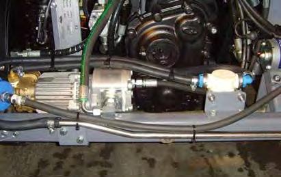
71 MAINTENANCE AIR CONDITIONER PRESSURE WASHER (OPTION) FOR SAFETY: Before leaving or servicing machine, stop on level surface, place drive lever in neutral, set parking brake, turn off machine, and remove key. Check the air conditioner hoses and connections for damage and leaks every 450 hours of operation. FOR SAFETY: Before leaving or servicing machine, stop on level surface, place drive lever in neutral, set parking brake, turn off machine, and remove key. Check the pressure washer wand and system hoses for wear and damage every 450 hours of operation. WANDER HOSE Check the pressure washer manifold filter for wear and damage every 450 hours of operation. FOR SAFETY: Before leaving or servicing machine, stop on level surface, place drive lever in neutral, set parking brake, turn off machine, and remove key. Check the wander hose and the adapter seal on the hopper for wear and damage every 450 hours of operation. 500ze YM180 ( ) 69
72 MAINTENANCE AUTOMATIC LUBRICATION SYSTEM FOR SAFETY: Before leaving or servicing machine, stop on level surface, place drive lever in neutral, set parking brake, turn off machine, and remove key. Check grease level in the automatic lubrication system grease container every 450 hours of operation. Fill the grease container as necessary. Use only grade NGL 1000 EP semi fluid grease to refill the grease container. Ensure the cam located inside the grease container is functioning properly every 450 hours of operation. FILLING THE AUTOMATIC LUBRICATION SYSTEM RESERVOIR 1. Remove the cap from the automatic lubrication system reservoir. 2. Pour grease into the reservoir. 3. Reinstall the cap onto the reservoir ze YM180 ( )
73 MAINTENANCE TILTING / LOWERING THE CAB TILTING THE CAB FOR SAFETY: Before leaving or servicing machine, stop on level surface, place drive lever in neutral, set parking brake, turn off machine, and remove key. LOWERING THE CAB 1. Lower the cab to the frame of the machine. 2. Be sure the safety hook is secure in the bracket. ATTENTION!: No personnel should be in the cab while it is being tilted or while it is in the tilted position. 1. Remove loose items from inside the cab. 2. Remove the lock down bracket located on the right rear of the cab from the frame of the machine. 3. Place the lock down bracket onto the lock down hook and reinstall the lock down bracket onto the frame of the machine. 3. Lift the safety hook handle located on the left rear side of the cab and tilt the cab. 500ze YM180 ( ) 71

74 MAINTENANCE TILTING / LOWERING THE HOPPER MANUALLY 6. Remove the hopper safety arm from the storage clips. FOR SAFETY: Before leaving or servicing machine, stop on level surface, place drive lever in neutral, set parking brake, turn off machine, and remove key. TILTING THE HOPPER MANUALLY Use the hopper pump to manually tilt the hopper if machine is disabled. 1. Remove right side panel from the machine. 2. Remove the pump handle from the storage area inside the left access door. 3. Insert the pump handle into the hopper pump. 4. Confirm the hopper pump needle valve knob is turned fully clockwise to ensure the needle valve is closed. 7. Position the receptacle end of the safety arm onto the frame of the machine and prop the tapered end of the safety arm against the hopper. WARNING: Raised hopper may fall. Engage hopper safety arm. FOR SAFETY: When using machine, make sure adequate clearance is available before raising hopper. Do not raise hopper when machine is on an incline. 5. Use the hopper pump to manually tilt the hopper. 8. Remove the pump handle from the hopper pump and return the pump handle to the storage location inside the left access door. If the machine is operable, see RAISING / LOWERING THE HOPPER section of this manual. If the machine is inoperable, see LOWERING THE HOPPER MANUALLY section of this manual ze YM180 ( )
75 MAINTENANCE LOWERING THE HOPPER MANUALLY 1. Remove the hopper safety arm from between the frame of the machine and the hopper and place the safety arm into the storage clips. 2. Slowly turn the hopper pump needle valve knob fully counterclockwise and allow the hopper to completely lower down to the frame of the machine. NOTE: Several personnel may be necessary to push the hopper over the center point so the weight of the hopper lowers the hopper. WARNING: Lift arm pinch point. Stay clear of hopper lift arms. NOTE: Keep personnel clear of the area around the hopper before manually lowering the hopper. 3. Turn the hopper pump needle valve knob fully clockwise to close the needle valve. NOTE: The power hopper tilt system will not operate if the hopper pump needle valve knob is left open. 500ze YM180 ( ) 73


76 MAINTENANCE TOWING / TRANSPORTING THE MACHINE TOWING THE MACHINE ATTENTION!: Do Not use the machine to push or tow other equipment. If the machine becomes disabled, it can be only towed from the tow point located at the front of the machine. TRANSPORTING THE MACHINE 1. Raise the brushes. FOR SAFETY: When loading machine onto truck or trailer, drain water tank and empty hopper before loading machine. 2. Position the front of the machine at the loading edge of the truck or trailer. FOR SAFETY: When loading machine onto truck or trailer, use winch. Do not drive the machine onto the truck or trailer unless the loading surface is horizontal AND is 380 mm (15 in) or less from the ground. 3. If the loading surface is horizontal and 380 mm (15 in) or less from the ground, drive the machine up onto the truck or trailer. Use the mechanical brake release to prevent damaging the propelling system when towing the machine. The mechanical brake release allows a disabled machine to be moved for a very short distance (1.5 km (1 mile) maximum) and at a speed not to exceed 8.0 km/h (5 mph). This machine is NOT intended to be towed a long distance or at a high speed. ATTENTION! Do not tow machine for distances greater than 1.5 km (1 mile) or damage may occur to the propelling system. Engage the parking brake. Open the water tank door. To engage the mechanical brake release tighten the nut on the mechanical brake release until it becomes more difficult to tighten the nut, and then tighten the nut two additional turns. Disengage the park brake when ready to tow the machine. Loosen the mechanical brake release when finished towing the machine. Do Not leave the mechanical brake release tightened during normal machine operation ze YM180 ( )
77 MAINTENANCE 4. To winch the machine onto the truck or trailer, attach the winching chains to the tow point. NOTE: Take care to not damage pressure washer hoses and fittings when attaching the winch to the tow points located located on the rear end of the machine. 8. Connect the tie down straps to the tie down points. NOTE: Take care to not damage pressure washer hoses and fittings when attaching the tie down straps to the tow points located on the rear end of the machine. 5. Position the machine as close to the front of the trailer or truck as possible. 6. Set the parking brake and place a block behind each wheel to prevent the machine from rolling. 7. Start the machine, place the machine into Work Mode 1, and lower the brushes. Turn off the machine. 9. Route the tie down straps to the opposite ends of the machine and hook them to the brackets on the floor of the trailer or truck. Tighten the tie down straps. NOTE: It may be necessary to install tie-down brackets to the floor of the trailer or truck. FOR SAFETY: When unloading machine off truck or trailer, use winch. Do not drive the machine off the truck or trailer unless the loading surface is horizontal AND 380 mm (15 in) or less from the ground. 10. If the loading surface is horizontal AND is 380 mm (15 in) or less from the ground, drive the machine off the truck or trailer. 500ze YM180 ( ) 75


78 MAINTENANCE MACHINE JACKING Front jacking locations are located on the frame directly in front of the front tires. Empty the hopper and water tank before jacking up the machine. Jack up the machine at the designated locations. Use a hoist or jack capable of supporting the weight of the machine. Use appropriately rated jack stands to support the machine. NOTE: Do Not jack machine up from under the battery packs. The battery packs could be damaged if the machine is jacked up from under the battery packs. FOR SAFETY: Before leaving or servicing machine, stop on level surface, place drive lever in neutral, set parking brake, turn off machine, and remove key. FOR SAFETY: When servicing machine, block machine tires before jacking machine up. Use a hoist or jack that will support the weight of the machine. Jack machine up at designated locations only. Support machine with jack stands. Rear jacking locations are located beneath the rear bumper and in front of each rear tire ze YM180 ( )
S9 SWEEPER PARTS MANUAL
 S9 SWEEPER PARTS MANUAL Clemas & Co. Unit 5 Ashchurch Business Centre, Alexandra Way, Tewkesbury, Gloucestershire, GL20 8NB. Tel: 01684 850777 Fax: 01684 850707 Email: info@clemas.co.uk Web: www.clemas.co.uk
For cleaning machines, parts & supplies click/visit
 SENTINEL Sweeper Operator Manual TennantTrue Parts North America / International For latest Parts manual or other language Operator manual, visit: www.tennantco.com/manuals 331000 Rev. 11 (2-2016) *331000*
SENTINEL R *331000* Sweeper Operator Manual. North America / International Rev. 05 ( )
") SENTINEL R Sweeper Operator Manual North America / International www.tennantco.com 331000 Rev. 05 (09-2008) *331000* This manual is furnished with each new model. It provides necessary operation and maintenance
SENTINEL R Sweeper Operator Manual North America / International www.tennantco.com 331000 Rev. 05 (09-2008) *331000* This manual is furnished with each new model. It provides necessary operation and maintenance
M20 *331391* (Gas/LPG) Scrubber- Sweeper English EN Operator Manual Rev. 16 (5-2016)
 Scrubber- Sweeper English EN Operator Manual Rev. 16 (5-2016)") M20 (Gas/LPG) Scrubber- Sweeper English EN Operator Manual R For the latest Parts manuals and other language Operator manuals, visit: www.tennantco.com/manuals 331391 Rev. 16 (5-2016) *331391* INTRODUCTION
M20 (Gas/LPG) Scrubber- Sweeper English EN Operator Manual R For the latest Parts manuals and other language Operator manuals, visit: www.tennantco.com/manuals 331391 Rev. 16 (5-2016) *331391* INTRODUCTION
M30 * * (Gas/LPG) Scrubber Sweeper English EN Operator Manual Rev. 11 (4-2015)
 Scrubber Sweeper English EN Operator Manual Rev. 11 (4-2015)") M30 (Gas/LPG) Scrubber Sweeper English EN Operator Manual For the latest parts manuals and other language Operator manuals, visit: www.tennantco.com/manuals 9004681 Rev. 11 (4-2015) *9004681* INTRODUCTION
M30 (Gas/LPG) Scrubber Sweeper English EN Operator Manual For the latest parts manuals and other language Operator manuals, visit: www.tennantco.com/manuals 9004681 Rev. 11 (4-2015) *9004681* INTRODUCTION
S30 * * (Gas/LPG) Sweeper English EN Operator Manual Rev. 06 ( ) To view, print or download the latest manual, visit:
 Sweeper English EN Operator Manual Rev. 06 ( ) To view, print or download the latest manual, visit:") S30 (Gas/LPG) Sweeper English EN Operator Manual To view, print or download the latest manual, visit: www.tennantco.com/manuals 9004624 Rev. 06 (02-2013) *9004624* This manual is furnished with each new
S30 (Gas/LPG) Sweeper English EN Operator Manual To view, print or download the latest manual, visit: www.tennantco.com/manuals 9004624 Rev. 06 (02-2013) *9004624* This manual is furnished with each new
S20. (Battery) Sweeper Operator Manual. North America / International. SweepMax System ShakeMax 360 TennantTrue Parts IRIS a Tennant Technology
 Sweeper Operator Manual. North America / International. SweepMax System ShakeMax 360 TennantTrue Parts IRIS a Tennant Technology") S20 (Battery) Sweeper Operator Manual SweepMax System ShakeMax 360 TennantTrue Parts IRIS a Tennant Technology North America / International For the latest Parts manuals and other language Operator manuals,
S20 (Battery) Sweeper Operator Manual SweepMax System ShakeMax 360 TennantTrue Parts IRIS a Tennant Technology North America / International For the latest Parts manuals and other language Operator manuals,
M20 *331421* (Diesel) Scrubber Sweeper English EN Operator Manual Rev. 11 ( )
 Scrubber Sweeper English EN Operator Manual Rev. 11 ( )") M20 (Diesel) Scrubber Sweeper English EN Operator Manual www.tennantco.com 331421 Rev. 11 (05-2013) *331421* INTRODUCTION This manual is furnished with each new model. It provides necessary operation and
M20 (Diesel) Scrubber Sweeper English EN Operator Manual www.tennantco.com 331421 Rev. 11 (05-2013) *331421* INTRODUCTION This manual is furnished with each new model. It provides necessary operation and
Operator Manual Rev. 06 *330270*
 6500 Operator Manual 330270 Rev. 06 *330270* This manual is furnished with each new TENNANT Model 6500. It provides necessary operating and preventive maintenance instructions. Read this manual completely
S10 PEDESTRIAN SWEEPER OPERATOR MANUAL
 S10 PEDESTRIAN SWEEPER OPERATOR MANUAL Clemas & Co. Unit 5 Ashchurch Business Centre, Alexandra Way, Tewkesbury, Gloucestershire, GL20 8NB. Tel: 01684 850777 Fax: 01684 850707 Email: info@clemas.co.uk
S20. (Gas/LPG) Sweeper Operator Manual. North America / International. SweepMax System ShakeMax 360 TennantTrue Parts IRIS a Tennant Technology
 Sweeper Operator Manual. North America / International. SweepMax System ShakeMax 360 TennantTrue Parts IRIS a Tennant Technology") S20 (Gas/LPG) Sweeper Operator Manual SweepMax System ShakeMax 360 TennantTrue Parts IRIS a Tennant Technology North America / International For the latest Parts manuals and other language Operator manuals,
S20 (Gas/LPG) Sweeper Operator Manual SweepMax System ShakeMax 360 TennantTrue Parts IRIS a Tennant Technology North America / International For the latest Parts manuals and other language Operator manuals,
S30 * * (Gas/LPG) Sweeper Operator Manual. North America / International. SweepMax R Plus TennantTrue R Parts IRIS R a Tennant Technology
 Sweeper Operator Manual. North America / International. SweepMax R Plus TennantTrue R Parts IRIS R a Tennant Technology") S30 (Gas/LPG) Sweeper Operator Manual SweepMax R Plus TennantTrue R Parts IRIS R a Tennant Technology North America / International For the latest parts manuals and other language Operator manuals, visit:
S30 (Gas/LPG) Sweeper Operator Manual SweepMax R Plus TennantTrue R Parts IRIS R a Tennant Technology North America / International For the latest parts manuals and other language Operator manuals, visit:
S30. (Diesel) Sweeper Operator Manual. North America / International. SweepMax Plus TennantTrue Parts IRIS a Tennant Technology
 Sweeper Operator Manual. North America / International. SweepMax Plus TennantTrue Parts IRIS a Tennant Technology") S30 (Diesel) Sweeper Operator Manual SweepMax Plus TennantTrue Parts IRIS a Tennant Technology North America / International For the latest Parts manuals and other language Operator manuals, visit: www.tennantco.com/manuals
S30 (Diesel) Sweeper Operator Manual SweepMax Plus TennantTrue Parts IRIS a Tennant Technology North America / International For the latest Parts manuals and other language Operator manuals, visit: www.tennantco.com/manuals
S20. (Diesel) Sweeper Operator Manual. North America / International. SweepMax System ShakeMax 360 TennantTrue Parts IRIS a Tennant Technology
 Sweeper Operator Manual. North America / International. SweepMax System ShakeMax 360 TennantTrue Parts IRIS a Tennant Technology") S20 (Diesel) Sweeper Operator Manual SweepMax System ShakeMax 360 TennantTrue Parts IRIS a Tennant Technology North America / International For the latest Parts manuals and other language Operator manuals,
S20 (Diesel) Sweeper Operator Manual SweepMax System ShakeMax 360 TennantTrue Parts IRIS a Tennant Technology North America / International For the latest Parts manuals and other language Operator manuals,
S20 * * (Gas/LPG) Sweeper Operator Manual. North America / International. SweepMaxt System ShakeMaxt 360 TennantTruet Parts and Supplies
 Sweeper Operator Manual. North America / International. SweepMaxt System ShakeMaxt 360 TennantTruet Parts and Supplies") S20 (Gas/LPG) Sweeper Operator Manual SweepMaxt System ShakeMaxt 360 TennantTruet Parts and Supplies North America / International www.tennantco.com 9006719 Rev. 02 (08-2011) *9006719* This manual is furnished
S20 (Gas/LPG) Sweeper Operator Manual SweepMaxt System ShakeMaxt 360 TennantTruet Parts and Supplies North America / International www.tennantco.com 9006719 Rev. 02 (08-2011) *9006719* This manual is furnished
S30. (Gas/LPG) Sweeper Operator Manual. North America / International. SweepMax Plus TennantTrue Parts IRIS a Tennant Technology
 Sweeper Operator Manual. North America / International. SweepMax Plus TennantTrue Parts IRIS a Tennant Technology") S30 (Gas/LPG) Sweeper Operator Manual SweepMax Plus TennantTrue Parts IRIS a Tennant Technology North America / International For the latest parts manuals and other language Operator manuals, visit: www.tennantco.com/manuals
S30 (Gas/LPG) Sweeper Operator Manual SweepMax Plus TennantTrue Parts IRIS a Tennant Technology North America / International For the latest parts manuals and other language Operator manuals, visit: www.tennantco.com/manuals
S20 * * (Gas/LPG) Sweeper Operator Manual. North America / International
 Sweeper Operator Manual. North America / International") S20 (Gas/LPG) Sweeper Operator Manual SweepMax System ShakeMax 360 TennantTrue Parts IRIS a Tennant Technology North America / International For the latest Parts manuals and other language Operator manuals,
S20 (Gas/LPG) Sweeper Operator Manual SweepMax System ShakeMax 360 TennantTrue Parts IRIS a Tennant Technology North America / International For the latest Parts manuals and other language Operator manuals,
(Electric) Sweeper English EN Operator Manual Rev. 08 ( ) *330569*
 Sweeper English EN Operator Manual Rev. 08 ( ) *330569*") 3640 (Electric) Sweeper English EN Operator Manual www.tennantco.com 330569 Rev. 08 (02-2008) *330569* This manual is furnished with each new model. It provides necessary operation and maintenance instructions.
3640 (Electric) Sweeper English EN Operator Manual www.tennantco.com 330569 Rev. 08 (02-2008) *330569* This manual is furnished with each new model. It provides necessary operation and maintenance instructions.
S20. (Diesel) Sweeper Operator Manual. North America / International. SweepMax System ShakeMax 360 TennantTrue Parts IRIS a Tennant Technology
 Sweeper Operator Manual. North America / International. SweepMax System ShakeMax 360 TennantTrue Parts IRIS a Tennant Technology") S20 (Diesel) Sweeper Operator Manual SweepMax System ShakeMax 360 TennantTrue Parts IRIS a Tennant Technology North America / International For the latest Parts manuals and other language Operator manuals,
S20 (Diesel) Sweeper Operator Manual SweepMax System ShakeMax 360 TennantTrue Parts IRIS a Tennant Technology North America / International For the latest Parts manuals and other language Operator manuals,
Operator Manual Rev. 02 *330950*
 6600 Operator Manual 330950 Rev. 02 *330950* This manual is furnished with each new TENNANT Model 6600. It provides necessary operating and preventive maintenance instructions. Read this manual completely
S30 * * (Diesel) Sweeper Operator Manual. North America / International. SweepSmart System TennantTrue Parts IRIS a Tennant Technology
 Sweeper Operator Manual. North America / International. SweepSmart System TennantTrue Parts IRIS a Tennant Technology") S30 (Diesel) Sweeper Operator Manual SweepSmart System TennantTrue Parts IRIS a Tennant Technology North America / International To view, print or download the latest manual, visit: www.tennantco.com/manuals
S30 (Diesel) Sweeper Operator Manual SweepSmart System TennantTrue Parts IRIS a Tennant Technology North America / International To view, print or download the latest manual, visit: www.tennantco.com/manuals
S30 * * (Gas/LPG) Sweeper Operator Manual. North America / International. SweepSmartt System Rev. 02 ( )
 Sweeper Operator Manual. North America / International. SweepSmartt System Rev. 02 ( )") S30 (Gas/LPG) Sweeper Operator Manual SweepSmartt System North America / International www.tennantco.com 9004080 Rev. 02 (12-2008) *9004080* This manual is furnished with each new model. It provides necessary
S30 (Gas/LPG) Sweeper Operator Manual SweepSmartt System North America / International www.tennantco.com 9004080 Rev. 02 (12-2008) *9004080* This manual is furnished with each new model. It provides necessary
*330140* (Diesel) (SN/ ) Sweeper Operator Manual. North America / International Rev. 18 ( ) TennantTrue R Parts
 (SN/ ) Sweeper Operator Manual. North America / International Rev. 18 ( ) TennantTrue R Parts") 800 (Diesel) (SN/ 004000 - ) Sweeper Operator Manual TennantTrue R Parts North America / International To view, print or download the latest manual, visit: www.tennantco.com/manuals 330140 Rev. 18 (10-2013)
800 (Diesel) (SN/ 004000 - ) Sweeper Operator Manual TennantTrue R Parts North America / International To view, print or download the latest manual, visit: www.tennantco.com/manuals 330140 Rev. 18 (10-2013)
(Gas/LPG) Sweeper Operator Manual. North America / International Rev. 05 ( ) *330910*
 Sweeper Operator Manual. North America / International Rev. 05 ( ) *330910*") 6650 (Gas/LPG) Sweeper Operator Manual North America / International www.tennantco.com 330910 Rev. 05 (03-2008) *330910* This manual is furnished with each new model. It provides necessary operation and
6650 (Gas/LPG) Sweeper Operator Manual North America / International www.tennantco.com 330910 Rev. 05 (03-2008) *330910* This manual is furnished with each new model. It provides necessary operation and
(Diesel) Sweeper Operator Manual. North America / International Rev. 05 ( ) *330950*
 Sweeper Operator Manual. North America / International Rev. 05 ( ) *330950*") 6650 (Diesel) Sweeper Operator Manual North America / International www.tennantco.com 330930 Rev. 05 (03-2008) *330950* This manual is furnished with each new model. It provides necessary operation and
6650 (Diesel) Sweeper Operator Manual North America / International www.tennantco.com 330930 Rev. 05 (03-2008) *330950* This manual is furnished with each new model. It provides necessary operation and
M30 * * (Gas/LPG) Scrubber -Sweeper Operator Manual. North America / International Rev. 09 ( )
 Scrubber -Sweeper Operator Manual. North America / International Rev. 09 ( )") M30 (Gas/LPG) Scrubber -Sweeper Operator Manual The Safe Scrubbing Alternative R ES R Extended Scrub System TennantTrue R Parts Hygenic R Fully Cleanable Tanks FloorSmartt Integrated Cleaning System IRISt
M30 (Gas/LPG) Scrubber -Sweeper Operator Manual The Safe Scrubbing Alternative R ES R Extended Scrub System TennantTrue R Parts Hygenic R Fully Cleanable Tanks FloorSmartt Integrated Cleaning System IRISt
S30 * * (Diesel) Sweeper Operator Manual. North America / International. SweepMax Plus TennantTrue Parts IRIS a Tennant Technology
 Sweeper Operator Manual. North America / International. SweepMax Plus TennantTrue Parts IRIS a Tennant Technology") S30 (Diesel) Sweeper Operator Manual SweepMax Plus TennantTrue Parts IRIS a Tennant Technology North America / International For the latest parts manuals and other language Operator manuals, visit: www.tennantco.com/manuals
S30 (Diesel) Sweeper Operator Manual SweepMax Plus TennantTrue Parts IRIS a Tennant Technology North America / International For the latest parts manuals and other language Operator manuals, visit: www.tennantco.com/manuals
M20 *331380* (Gas/LPG) Scrubber -Sweeper Operator Manual. North America / International Rev. 06 (5-2009) The Safe Scrubbing Alternative R
 Scrubber -Sweeper Operator Manual. North America / International Rev. 06 (5-2009) The Safe Scrubbing Alternative R") M20 (Gas/LPG) Scrubber -Sweeper Operator Manual The Safe Scrubbing Alternative R R Hygenic Fully Cleanable Tanks FloorSmartt Integrated Cleaning System R ES Extended Scrub System North America / International
M20 (Gas/LPG) Scrubber -Sweeper Operator Manual The Safe Scrubbing Alternative R R Hygenic Fully Cleanable Tanks FloorSmartt Integrated Cleaning System R ES Extended Scrub System North America / International
S30 * * (Gas/LPG) Sweeper Operator Manual. North America / International. SweepSmartt System TennantTrue R Parts IRISt a Tennant Technology
 Sweeper Operator Manual. North America / International. SweepSmartt System TennantTrue R Parts IRISt a Tennant Technology") S30 (Gas/LPG) Sweeper Operator Manual SweepSmartt System TennantTrue R Parts IRISt a Tennant Technology North America / International To view, print or download the latest manual, visit: www.tennantco.com/manuals
S30 (Gas/LPG) Sweeper Operator Manual SweepSmartt System TennantTrue R Parts IRISt a Tennant Technology North America / International To view, print or download the latest manual, visit: www.tennantco.com/manuals
(Diesel) Sweeper Operator Manual. North America / International Rev. 05 ( ) *33089*
 Sweeper Operator Manual. North America / International Rev. 05 ( ) *33089*") 6600 (Diesel) Sweeper Operator Manual North America / International www.tennantco.com 330890 Rev. 05 (03-2008) *33089* This manual is furnished with each new model. It provides necessary operation and
6600 (Diesel) Sweeper Operator Manual North America / International www.tennantco.com 330890 Rev. 05 (03-2008) *33089* This manual is furnished with each new model. It provides necessary operation and
S30 * * (Gas/LPG) Sweeper Operator Manual. North America / International. SweepSmart System TennantTrue Parts IRIS a Tennant Technology
 Sweeper Operator Manual. North America / International. SweepSmart System TennantTrue Parts IRIS a Tennant Technology") S30 (Gas/LPG) Sweeper Operator Manual SweepSmart System TennantTrue Parts IRIS a Tennant Technology North America / International To view, print or download the latest manual, visit: www.tennantco.com/manuals
S30 (Gas/LPG) Sweeper Operator Manual SweepSmart System TennantTrue Parts IRIS a Tennant Technology North America / International To view, print or download the latest manual, visit: www.tennantco.com/manuals
*330970* (Gas/LPG) ( ) (GM Engine) Rider Scrubber Operator Manual. North America / International Rev. 04 (3-2007)
 ( ) (GM Engine) Rider Scrubber Operator Manual. North America / International Rev. 04 (3-2007)") 7400 (Gas/LPG) (007000 - ) (GM Engine) Rider Scrubber Operator Manual The Safe Scrubbing Alternative R R ES Extended Scrub System North America / International www.tennantco.com 330970 Rev. 04 (3-2007)
7400 (Gas/LPG) (007000 - ) (GM Engine) Rider Scrubber Operator Manual The Safe Scrubbing Alternative R R ES Extended Scrub System North America / International www.tennantco.com 330970 Rev. 04 (3-2007)
400 Series *YM036* Global. YM036 Rev. 05 ( )
") 400 Series Global www.greenmachines.com YM036 Rev. 05 (12-2015) *YM036* INTRODUCTION This manual is furnished with each new model. It provides necessary operation and maintenance instructions. Read this
400 Series Global www.greenmachines.com YM036 Rev. 05 (12-2015) *YM036* INTRODUCTION This manual is furnished with each new model. It provides necessary operation and maintenance instructions. Read this
MM185 Rev. 11 (9-94)
") 465 480 490 MM85 Rev. (9-94) This manual is furnished with each new TENNANT Model 465, 480, and 490. It provides necessary operating and preventive maintenance instructions. Read this manual completely
465 480 490 MM85 Rev. (9-94) This manual is furnished with each new TENNANT Model 465, 480, and 490. It provides necessary operating and preventive maintenance instructions. Read this manual completely
(Battery) Rider Sweeper Operator Manual
 Rider Sweeper Operator Manual") 6100 (Battery) Rider Sweeper Operator Manual VCS Filter Shaker TennantTrue Parts IRIS a Tennant Technology North America / International For the latest Parts manuals and other language Operator manuals,
6100 (Battery) Rider Sweeper Operator Manual VCS Filter Shaker TennantTrue Parts IRIS a Tennant Technology North America / International For the latest Parts manuals and other language Operator manuals,
M30. (Diesel) Scrubber Sweeper Operator Manual. North America / International Rev. 07 (6-2011) * * The Safe Scrubbing Alternative
 Scrubber Sweeper Operator Manual. North America / International Rev. 07 (6-2011) * * The Safe Scrubbing Alternative") M30 (Diesel) Scrubber Sweeper Operator Manual The Safe Scrubbing Alternative Hygenic Fully Cleanable Tanks FloorSmart Integrated Cleaning System ES Extended Scrub System North America / International www.tennantco.com
M30 (Diesel) Scrubber Sweeper Operator Manual The Safe Scrubbing Alternative Hygenic Fully Cleanable Tanks FloorSmart Integrated Cleaning System ES Extended Scrub System North America / International www.tennantco.com
M30 * * (Gas/LPG) Scrubber -Sweeper Operator Manual. North America / International Rev. 06 ( ) The Safe Scrubbing Alternative R
 Scrubber -Sweeper Operator Manual. North America / International Rev. 06 ( ) The Safe Scrubbing Alternative R") M30 (Gas/LPG) Scrubber -Sweeper Operator Manual The Safe Scrubbing Alternative R R Hygenic Fully Cleanable Tanks FloorSmartt Integrated Cleaning System R ES Extended Scrub System North America / International
M30 (Gas/LPG) Scrubber -Sweeper Operator Manual The Safe Scrubbing Alternative R R Hygenic Fully Cleanable Tanks FloorSmartt Integrated Cleaning System R ES Extended Scrub System North America / International
*330120* (Gas/LPG) (S/N ) Sweeper Operator Manual. North America / International Rev. 25 (5-2017) TennantTrue R Parts
 (S/N ) Sweeper Operator Manual. North America / International Rev. 25 (5-2017) TennantTrue R Parts") 800 (Gas/LPG) (S/N 004000-008399) Sweeper Operator Manual TennantTrue R Parts North America / International For latest Parts manuals and other Operator language manuals, visit: www.tennantco.com/manuals
800 (Gas/LPG) (S/N 004000-008399) Sweeper Operator Manual TennantTrue R Parts North America / International For latest Parts manuals and other Operator language manuals, visit: www.tennantco.com/manuals
* * (Kubota 4i Diesel) (SN/ ) Sweeper Operator Manual. North America / International Rev. 04 (1-2017)
 (SN/ ) Sweeper Operator Manual. North America / International Rev. 04 (1-2017)") 800 (Kubota 4i Diesel) (SN/ 008015- ) Sweeper Operator Manual TennantTruet Parts and Supplies North America / International For the latest Parts manuals and other language Operator manuals, visit: www.tennantco.com/manuals
800 (Kubota 4i Diesel) (SN/ 008015- ) Sweeper Operator Manual TennantTruet Parts and Supplies North America / International For the latest Parts manuals and other language Operator manuals, visit: www.tennantco.com/manuals
M30 * * (Diesel) Scrubber -Sweeper Operator Manual. North America / International Rev. 03 ( ) The Safe Scrubbing Alternative R
 Scrubber -Sweeper Operator Manual. North America / International Rev. 03 ( ) The Safe Scrubbing Alternative R") M30 (Diesel) Scrubber -Sweeper Operator Manual The Safe Scrubbing Alternative R R Hygenic Fully Cleanable Tanks FloorSmartt Integrated Cleaning System R ES Extended Scrub System North America / International
M30 (Diesel) Scrubber -Sweeper Operator Manual The Safe Scrubbing Alternative R R Hygenic Fully Cleanable Tanks FloorSmartt Integrated Cleaning System R ES Extended Scrub System North America / International
Operator Manual Rev. 08 (3-2006) *330190*
 *330190*") 8210 Operator Manual www.tennantco.com 330190 Rev. 08 (3-2006) *330190* This manual is furnished with each new model. It provides necessary operation and maintenance instructions. MACHINE DATA Read this
8210 Operator Manual www.tennantco.com 330190 Rev. 08 (3-2006) *330190* This manual is furnished with each new model. It provides necessary operation and maintenance instructions. MACHINE DATA Read this
This machine will provide excellent service. However, the best results will be obtained at minimum costs if:
 This manual is furnished with each new TENNANT Model 810D. It provides necessary operating and preventive maintenance instructions. Read this manual completely and understand the machine before operating
(Electric) Sweeper Operator Manual. North America / International Rev. 11 (2-2010) *330410*
 Sweeper Operator Manual. North America / International Rev. 11 (2-2010) *330410*") 6200 (Electric) Sweeper Operator Manual North America / International www.tennantco.com 330410 Rev. 11 (2-2010) *330410* This manual is furnished with each new model. It provides necessary operation and
6200 (Electric) Sweeper Operator Manual North America / International www.tennantco.com 330410 Rev. 11 (2-2010) *330410* This manual is furnished with each new model. It provides necessary operation and
Operator Manual Rev. 08 (3-2006) *330060*
 *330060*") 8200 Operator Manual www.tennantco.com 330060 Rev. 08 (3-2006) *330060* This manual is furnished with each new model. It provides necessary operation and maintenance instructions. MACHINE DATA Read this
8200 Operator Manual www.tennantco.com 330060 Rev. 08 (3-2006) *330060* This manual is furnished with each new model. It provides necessary operation and maintenance instructions. MACHINE DATA Read this
355D. Operator Manual MM301
 355D Operator Manual MM301 This manual is furnished with each new TENNANT Model 355. It provides necessary operating and preventive maintenance instructions. Read this manual completely and understand
(Battery) Rider Sweeper Operator Manual
 Rider Sweeper Operator Manual") 6100 (Battery) Rider Sweeper Operator Manual VCS Filter Shaker TennantTrue Parts IRIS a Tennant Technology North America / International To view, print or download the latest manual, visit: www.tennantco.com/manuals
6100 (Battery) Rider Sweeper Operator Manual VCS Filter Shaker TennantTrue Parts IRIS a Tennant Technology North America / International To view, print or download the latest manual, visit: www.tennantco.com/manuals
ATLV Litter Vacuum Operator Manual. North America / International. TennantTrue Parts and Supplies Rev. 16 ( ) *330510*
 *330510*") ATLV 4300 Litter Vacuum Operator Manual TennantTrue Parts and Supplies North America / International To view, print or download the latest manual, visit: www.tennantco.com/manuals 330510 Rev. 16 (04-2012)
ATLV 4300 Litter Vacuum Operator Manual TennantTrue Parts and Supplies North America / International To view, print or download the latest manual, visit: www.tennantco.com/manuals 330510 Rev. 16 (04-2012)
Operator Manual MM311
 8400 Operator Manual MM311 This manual is furnished with each new TENNANT Model 8400. It provides necessary operating and preventive maintenance instructions. Read this manual completely and understand
This machine will provide excellent service. However, the best results will be obtained at minimum costs if:
 This manual is furnished with each new TENNANT Model 385DLH. It provides necessary operating and preventive maintenance instructions. Read this manual completely and understand the machine before operating
S10. (Battery) Sweeper Operator Manual. North America / International Rev. 06 (2-2018) *331580*
 Sweeper Operator Manual. North America / International Rev. 06 (2-2018) *331580*") S10 (Battery) Sweeper Operator Manual North America / International For the latest parts manual or other language operator manual, visit: www.tennantco.com/manuals 331580 Rev. 06 (2-2018) *331580* This
S10 (Battery) Sweeper Operator Manual North America / International For the latest parts manual or other language operator manual, visit: www.tennantco.com/manuals 331580 Rev. 06 (2-2018) *331580* This
Operator Manual MM300
 355 Operator Manual MM300 This manual is furnished with each new TENNANT Model 355. It provides necessary operating and preventive maintenance instructions. Read this manual completely and understand the
(Gas/LPG) Sweeper Operator Manual Rev. 11 (2-2010) North America / International *330370*
 Sweeper Operator Manual Rev. 11 (2-2010) North America / International *330370*") 6200 (Gas/LPG) Sweeper Operator Manual North America / International www.tennantco.com 330370 Rev. 11 (2-2010) *330370* This manual is furnished with each new model. It provides necessary operation and
6200 (Gas/LPG) Sweeper Operator Manual North America / International www.tennantco.com 330370 Rev. 11 (2-2010) *330370* This manual is furnished with each new model. It provides necessary operation and
Battery Sweeper Operator Manual
 S8 Battery Sweeper Operator Manual Model Part No.: MS85004 MS85904 UK 9001217 Rev. 01 (12-05) TENNANT N.V. Industrielaan 6 5405 AB P.O. Box 6 5400 AA Uden-The Netherlands europe@tennantco.com www.tennantco.com
(Diesel) Sweeper Operator Manual. North America / International. MM431 Rev. 12 ( ) *MM431*
 Sweeper Operator Manual. North America / International. MM431 Rev. 12 ( ) *MM431*") 6400 (Diesel) Sweeper Operator Manual North America / International www.tennantco.com MM431 Rev. 12 (04-2009) *MM431* This manual is furnished with each new model. It provides necessary operation and maintenance
6400 (Diesel) Sweeper Operator Manual North America / International www.tennantco.com MM431 Rev. 12 (04-2009) *MM431* This manual is furnished with each new model. It provides necessary operation and maintenance
S10 *331580* (Electric) Sweeper Operator Manual Rev. 03 (1-2010)
 Sweeper Operator Manual Rev. 03 (1-2010)") S10 (Electric) Sweeper Operator Manual www.tennantco.com 331580 Rev. 03 (1-2010) *331580* This manual is furnished with each new model. It provides necessary operation and maintenance instructions. Read
S10 (Electric) Sweeper Operator Manual www.tennantco.com 331580 Rev. 03 (1-2010) *331580* This manual is furnished with each new model. It provides necessary operation and maintenance instructions. Read
Operator Manual MM309
 810 Operator Manual MM309 This manual is furnished with each new TENNANT Model 810. It provides necessary operating and preventive maintenance instructions. Read this manual completely and understand the
Log Splitter. Owner/Operator Manual. Models HCWP1-26
 Log Splitter Owner/Operator Manual Models HCWP1-26 SAFETY..........................2 SAFETY WARNING SYMBOL.........3 SAFETY RULES.................. 4-5 SPECIFICATIONS................. 6 CONTROLS AND FEATURES.......
M20 *331410* (Diesel) Scrubber -Sweeper Operator Manual. North America / International Rev. 06 (5-2009) The Safe Scrubbing Alternative R
 Scrubber -Sweeper Operator Manual. North America / International Rev. 06 (5-2009) The Safe Scrubbing Alternative R") M20 (Diesel) Scrubber -Sweeper Operator Manual The Safe Scrubbing Alternative R Hygenic R Fully Cleanable Tanks FloorSmartt Integrated Cleaning System R ES Extended Scrub System North America / International
M20 (Diesel) Scrubber -Sweeper Operator Manual The Safe Scrubbing Alternative R Hygenic R Fully Cleanable Tanks FloorSmartt Integrated Cleaning System R ES Extended Scrub System North America / International
This machine will provide excellent service. However, the best results will be obtained at minimum costs if:
 235E MM165 This manual is furnished with each new TENNANT Model 235E. It provides necessary operating and preventive maintenance instructions. Read this manual completely and understand the machine before
Operator Manual. Patents Pending. The safe scrubbing alternativet Rev. 05 *330690*
 7100 Patents Pending The safe scrubbing alternativet Operator Manual 330690 Rev. 05 *330690* This manual is furnished with each new TENNANT Model 7100. It provides necessary operating and preventive maintenance
Riding Your Halo Go Before You Begin Safety Alerts
 HALO GOTM Before You Begin---------------------01 Riding Your Halo Go-----------07-10 Main Components-------------------02 Safety Alerts--------------------------11 Charging Your Batteries------------03
5100 Automatic Battery Scrubber
 5100 Automatic Battery Scrubber This manual is furnished with each new model. It provides necessary operation and maintenance instructions. Read this manual completely and understand the machine before
T12. (Battery) Rider Scrubber Operator Manual. North America / International
 Rider Scrubber Operator Manual. North America / International") T12 (Battery) Rider Scrubber Operator Manual The Safe Scrubbing Alternative TennantTrue Parts IRIS a Tennant Technology Insta Fit Adapter North America / International For the latest parts manuals and
T12 (Battery) Rider Scrubber Operator Manual The Safe Scrubbing Alternative TennantTrue Parts IRIS a Tennant Technology Insta Fit Adapter North America / International For the latest parts manuals and
6100 BATTERY SWEEPER OPERATOR MANUAL
 6100 BATTERY SWEEPER OPERATOR MANUAL Clemas & Co. Unit 5 Ashchurch Business Centre, Alexandra Way, Tewkesbury, Gloucestershire, GL20 8NB. Tel: 01684 850777 Fax: 01684 850707 Email: info@clemas.co.uk Web:
Service Manual Rev. 02 (8 11)
") 7100 Service Manual 330695 Rev. 02 (8 11) This service manual is intended to be an aid for the disassembly and reassembly of your TENNANT Model 7100. The set is organized into Four major groups: General
7100 Service Manual 330695 Rev. 02 (8 11) This service manual is intended to be an aid for the disassembly and reassembly of your TENNANT Model 7100. The set is organized into Four major groups: General
B5/B7 Walk-Behind Battery Burnisher
 B5/B7 Walk-Behind Battery Burnisher English EN Operator Manual TennantTrue Parts For latest Parts manual and other language Operator manuals, visit: www.tennantco.com/manuals Europe www.tennantco.com 9011496
Property of American Airlines
 Section 2. Operation 1. GENERAL FOR EMERGENCY OPERATING INSTRUCTIONS REFER TO CHAPTER 1, SECTION 3. This section contains instructions for operation of the B350. A discussion of the principles of operation
Service Manual Rev. 02 (3-02)
") 7200 Service Manual 330045 Rev. 02 (3-02) This service manual is intended to be an aid for the disassembly and reassembly of your TENNANT Model 7200 ride on scrubber. The set is organized into four major
7200 Service Manual 330045 Rev. 02 (3-02) This service manual is intended to be an aid for the disassembly and reassembly of your TENNANT Model 7200 ride on scrubber. The set is organized into four major
Towing and Road Service Guide For The 2010 Lexus HS250H. Quality and Education Services AAA Automotive 1000 AAA Drive Heathrow, FL 32746
 Towing and Road Service Guide For The 2010 Lexus HS250H Quality and Education Services AAA Automotive 1000 AAA Drive Heathrow, FL 32746 October 7, 2009 Index General Vehicle Information Major Component
Operator Manual Rev. 04 *330580*
 3640 Operator Manual 330580 Rev. 04 *330580* This manual is furnished with each new TENNANT Model 3640 sweeper. It provides necessary operating and preventive maintenance instructions. Read this manual
Operator Manual. MM425 Rev. 10. *mm425*
 7400 Operator Manual MM425 Rev. 10 *mm425* This manual is furnished with each new TENNANT Model 7400. It provides necessary operating and preventive maintenance instructions. Read this manual completely
Litter Hawkt *330470* Operator Manual Rev. 07 ( )
") Litter Hawkt Operator Manual www.tennantco.com 330470 Rev. 07 (12-2005) *330470* This manual is furnished with each new model. It provides necessary operation and maintenance instructions. MACHINE DATA
Litter Hawkt Operator Manual www.tennantco.com 330470 Rev. 07 (12-2005) *330470* This manual is furnished with each new model. It provides necessary operation and maintenance instructions. MACHINE DATA
WheelieSafe. WheelieSafe. User Manual. Motorized Trolley. Distributor:
 WheelieSafe Motorized Trolley WheelieSafe Distributor: User Manual You must read this manual before using your WheelieSafe trolley P/N: 9023100 Rev. 01/16 Table of contents Contents Pages Safety Symbols,
Operator Manual. MP425EN Rev. 10. *mp425en*
 7400 Operator Manual MP425EN Rev. 10 *mp425en* This manual is furnished with each new TENNANT Model 7400. It provides necessary operating and preventive maintenance instructions. Read this manual completely
WILDFIRE OPERATOR TRAINING MANUAL
 WILDFIRE OPERATOR TRAINING MANUAL 1 WildFire Component Locations Turn Signal Switch Accessory Switch Panel Generator Start/Stop Switch and Hour Meter Fig. 1 Brake Pedal Gas Pedal 2 WildFire Component Locations
SERVICE MANUAL (2)
") Terra 128B - 132B SERVICE MANUAL 146 0721 000(2)2003-04 INDEX GENERAL INFORMATION 3 MACHINE LIFTING 3 MACHINE TRANSPORTATION 3 OTHER AVAILABLE MANUALS 3 SAFETY - ACCIDENT PREVENTION 4 GENERAL SAFETY RULES
Terra 128B - 132B SERVICE MANUAL 146 0721 000(2)2003-04 INDEX GENERAL INFORMATION 3 MACHINE LIFTING 3 MACHINE TRANSPORTATION 3 OTHER AVAILABLE MANUALS 3 SAFETY - ACCIDENT PREVENTION 4 GENERAL SAFETY RULES
Trench Filler for Compact Utility Loaders
 Form No. 3353-608 Rev A Trench Filler for Compact Utility Loaders Model No. 22472 260000001 and Up Operator s Manual Register your product at www.toro.com Original Instructions (EN) Contents Page Introduction................................
B5/B7 Walk-Behind Battery Burnisher
 B5/B7 Walk-Behind Battery Burnisher English EN Operator Manual TennantTrue Parts North America / International www.tennantco.com For the latest Parts manuals and other language Operator manuals, visit:
SR5730. INSTRUCTIONS FOR USE Models , , /08 FORM NO
 SR5730 INSTRUCTIONS FOR USE Models 505-945, 505-946, 505-959 5/08 FORM NO. 56041764 TABLE OF CONTENTS Introduction... 4 Cautions and Warnings... 5 Symbols... 6 Specifications... 8-9 Machine Preparation...
COLLECTOR 37 USER MANUAL
 COLLECTOR 37 USER MANUAL A B E F C D H 2 G ENGLISH INTRODUCTION POWERBOSS,Inc. leaders in the production of sweeping machines, are pleased to welcome you as an owner of the Collector 37 sweeper machine.
Towing and Road Service Guide For Lexus LS 600h L. Quality and Education Services AAA Automotive 1000 AAA Drive Heathrow, FL 32746
 Towing and Road Service Guide For Lexus LS 600h L Quality and Education Services AAA Automotive 1000 AAA Drive Heathrow, FL 32746 June 15, 2007 Index General Towing Information Special Precautions 3 Hybrid
Towing and Road Service Guide For The Lexus ES300h. Quality and Education Services AAA Automotive 1000 AAA Drive Heathrow, FL 32746
 Towing and Road Service Guide For The Lexus ES300h Quality and Education Services AAA Automotive 1000 AAA Drive Heathrow, FL 32746 September 7, 2012 1 Index General Vehicle Information Major Component
NILFISK BA 500 Service Manual
 NILFISK BA 500 Service Manual Model 66324400 12/94 Form Number 043023 TABLE OF CONTENTS Batteries...21 Brush Drive Belt Adjustment Or Replacement...7 Brush Drive Motor - Carbon brush Inspection... 8 Brush
Towing and Road Service Guide For The Lexus CT200h. Quality and Education Services AAA Automotive 1000 AAA Drive Heathrow, FL 32746
 Towing and Road Service Guide For The Lexus CT200h Quality and Education Services AAA Automotive 1000 AAA Drive Heathrow, FL 32746 January 4 th, 2011 1 Index General Vehicle Information Major Component
North Dakota State University Grounds Maintenance Equipment
 North Dakota State University Grounds Maintenance Equipment I. Introduction Grounds maintenance equipment is an important part of the work activities on NDSU campus. They can make grounds maintenance jobs
The following procedures should be observed to ensure safe driving.
 Driving the vehicle The following procedures should be observed to ensure safe driving. n Starting the hybrid system ( P. 162) n Driving STEP 1 With the brake pedal depressed, shift the shift lever to
Electric Car User Manual
 Electric Car User Manual The owner s manual contains important safety information as well as assembly, use and maintenance instructions. The Ride-on Car must be assembled by an adult who has read and understands
before serial number 2214
 before serial number 2214 Contents Page Safety Rules... 3 Pre-operational & Safety Inspection... 4 Operating Instructions... 6 Transport... 12 Maintenance & Routine Service... 12 Specifications... 14 SAFETY
Retriever 4600 OPERATOR MANUAL Advance MODEL
 Retriever 4600 OPERATOR MANUAL Advance MODEL 56416000 9/97 revised 7/00 Form Number 56041389 TABLE OF CONTENTS Page Introduction...2 Parts and Service...2 Nameplate...2 Uncrating the Machine...2 Cautions
B10 Rider Burnisher * * English EN Operator Manual. North America / International. QA Controls Supervisor Settings TennantTrue Parts
 B10 Rider Burnisher English EN Operator Manual QA Controls Supervisor Settings TennantTrue Parts To view, print or download the latest manual, visit: www.tennantco.com/manuals North America / International
Sentry Carpet Maintainer. Operator and Parts Manual. Model No.: PAC Rev. 00 (09-99) Patent No.
 Patent No.") Sentry 2300 Patent No. : 5,611,106 Carpet Maintainer Model No.: 608660 608661 - PAC Operator and Parts Manual NOBLES 12875 RANSOM STREET HOLLAND MI 49424 U.S.A. CUSTOMER SERVICE: 1-800-365-6625 FAX: 1
Sentry 2300 Patent No. : 5,611,106 Carpet Maintainer Model No.: 608660 608661 - PAC Operator and Parts Manual NOBLES 12875 RANSOM STREET HOLLAND MI 49424 U.S.A. CUSTOMER SERVICE: 1-800-365-6625 FAX: 1
Operator Manual Rev. 04 *330230*
 6100 Operator Manual 330230 Rev. 04 *330230* This manual is furnished with each new TENNANT Model 6100. It provides necessary operating and preventive maintenance instructions. Read this manual completely
KING COBRA/CALIBER GRASS COLLECTION SYSTEM PARTS & OPERATORS MANUAL
 KING COBRA/CALIBER GRASS COLLECTION SYSTEM PARTS & OPERATORS MANUAL GRASS CATCHER W/WEIGHTS: TUBE KITS: BLOWER KITS: 52 542128 52 542119 5101002 60 542129 60 542120 5101003 2 WORLDLAWN POWER EQUIPMENT
Operator Manual. The most important component is you. This operator manual. has information for. all models of series. B plus some options and
 Operator Manual This operator manual has information for all models of series B plus some options and accessories. Some of the illustrations and information may not apply to your truck. The most important
Worldlawn Power Equipment, Inc. Industrial Park 2415 Ashland Ave. Beatrice, NE Toll Free Number:
 Operator s Manual R WYZ48/52/60CS BAGGER Worldlawn Power Equipment, Inc. Industrial Park 2415 Ashland Ave. Beatrice, NE 68310 Toll Free Number: 1-800-267-4255 OPERATOR S MANUAL This catcher manual is for
STOP. 44" High Speed Sweeper. Operator's Manual. Model No Safety Assembly Operation Maintenance Parts
 Operator's Manual STOP 44" High Speed Sweeper Model No. 486.029 DO NOT RETURN TO STORE For Missing Parts or Assembly Questions Call 1-866-576-8388 CAUTION: Before using this product, read this manual and
BUCKET SWEEPER OPERATORS & PARTS MANUAL 2852 & 3174 SERIES
 OM628 BUCKET SWEEPER OPERATORS & PARTS MANUAL 2852 & 3174 SERIES MODEL 12002-5 FOOT WIDE X 24 INCH DIAMETER (SKID-STEER) MODEL 12004-6 FOOT WIDE X 24 INCH DIAMETER (SKID-STEER) MODEL 12017-6 FOOT WIDE
SECTION 5 IN CASE OF AN EMERGENCY. In case of an emergency
 IN CASE OF AN EMERGENCY SECTION 5 In case of an emergency If your vehicle will not start................................... 360 If your hybrid system stalls while driving....................... 364 If
EW-09. Owner s Manual. (888) Customer Service. (888) Service
 Customer Service. (888) Service") EW-09 Owner s Manual www.ewheelsdealers.com (888) 305-0881 Customer Service (888) 571-2845 0 Service Table of Contents Page 2 - Feature Guide Page 3 - Product Specifications Page 4 - Operation of Scooter
EW-09 Owner s Manual www.ewheelsdealers.com (888) 305-0881 Customer Service (888) 571-2845 0 Service Table of Contents Page 2 - Feature Guide Page 3 - Product Specifications Page 4 - Operation of Scooter
2015 Scion iq Quick Reference Guide
 2015 Scion iq Quick Reference Guide 2015 Scion iq This Quick Reference Guide is a summary of basic vehicle operations. It contains brief descriptions of fundamental operations so you can locate and use