Check List for Optimal Filter Performance
|
|
|
- Verity Bradford
- 5 years ago
- Views:
Transcription
1
2 Check List for Optimal Filter Performance There should be no back-pressure on the flush line. A 1 valve should have a 2 waste line, and a 1.5" or 2 valve should have a 3 waste line. Do not use rubber hosing or flexible tubing for the waste line. The differential pressure gauge should be mounted within 3 feet of the filter. Long tubing lines will result in faulty gauge readings. The water supply line to the piston should be connected to an external water source, via a solenoid valve, and filtered by a ¼ mini filter. The fitting on the side of all pistons is for venting only. It should be open to atmospheric pressure and pointing toward the ground. Sealant should be applied on the contact points on the backside of the D/P gauge to protect it from water. The D/P gauge should be mounted such that the blue fitting is closest to the ground to prevent shorting of the contact points in the event of a water leak. If the filter outlet discharges to a tank, or to open atmosphere, a valve should be installed at the filter outlet to maintain a minimum working pressure of 15 PSI during the cleaning cycle. If the flush valve fails to open or close, verify the connections to the controller are wired correctly (see diagram on pg.18). A surge protector should be installed before the electronic controller. It is recommended that a pressure gauge be installed on the inlet of the filter. The filter should be oriented so that the unfiltered media source is directed to the inlet, the manifold closest to the cover. The outlet, the manifold closest to the flush line is the source of filtered media. To ensure proper installation, pictures with contact information to info@tekleen.com before startup. For further help, video tutorials may be found at goo.gl/qnkvr4
3 Table of Contents SECTION I INTRODUCTION 1.1 Description Theory of Operation Recommended Applications Design Features Filter Specification Chart 3 SECTION II INSTALLATION AND HOOK-UP 2.1 Mechanical Hook-Up and Orientation Plumbing Hook-Up Piston, Electric Ball Valve Installation, & Solenoid Valve Installation GB6, D/P Gauge, Electric Ball Valve, & Solenoid Valve Connections 5 SECTION III OPERATION AND ADJUSTMENTS 3.1 Start-up Cleaning Cycle Requirements 7 SECTION IV MAINTENANCE 4.1 Shutdown Procedure Filter Cleaning Dirt Collector Replacement Piston Removal/Replacement Motor Removal/Replacement Periodic Inspection 11 SECTION V TROUBLESHOOTING GUIDE 5.1 Excessive pressure drop through filter without flushing Frequent or continuous flushing while filling main pipeline Frequent flushing during normal operation Screen Will Not Clean Properly 12 SECTION VI SPARE PARTS 6.1 Recommended Spare Parts Spare Parts List 12 APPENDICES Appendix I Special Installation 13 Appendix II Alternate Flushing Methods 13 Appendix III Piston 14 ILLUSTRATIONS LPF Cutaway 16 LPF with GB6 17 LPF Wiring Diagram Motor Drive 18 2 x LPF with GB x LPF Wiring Diagram Motor Drive 20 Particulate Removal Process 21 Pressure Drop vs. Screen Size 22 WARRANTY 23
4 SECTION I INTRODUCTION 1.1 Description The LPF series models (Low Pressure Filter) are automatic, self cleaning screen type water filters. The filtration system consists of a tank body, a first stage coarse screen, a second stage fine screen, an electric motor, a flushing valve, a solenoid valve, and an electronic controller. 1.2 Theory of Operation Pressurized water enters the filter inlet and travels through a 3/8" perforated stainless steel coarse screen (¼ for smaller models) where large particles are pre-filtered. The water then passes through a fine mesh stainless steel screen where small contaminants (down to 10 microns in size) are filtered out. The clean water then exits through the outlet of the filter. When the fine screen becomes contaminated, a pressure differential is sensed causing the automatic controller to open the flushing valve and start the electric motor. When the flush valve opens, an atmospheric pressure path is established, causing the clean water to reverse flow at the point of suction across the filter element. This process removes contaminants from the screen, sending the dirty water through the nozzles and the dirt collector mechanism and out the flush valve. As the electric motor rotates the dirt collector, water passes through the nozzles, thus vacuuming the entire surface area of the filter element. When the screen is clean, the unit automatically closes the electric valve, returning the filter to normal operation. The entire cleaning cycle takes approximately seconds. It should be noted that even during the flush cycle, the filtration process continues uninterrupted. 1
5 1.3 Recommended Applications Tekleen filters are ideal for filtering out silt, scale, sand, rust, dirt and organic material like algae, zebra mussels, and clams from virtually all types of water sources. 1.4 Design Features Among the many features of the LPF models is an avoidance of forcing contaminated water back into the system, which often happens with sand media filters. LPF filters will deliver clean water or no water at all. The most predominant feature is its ability to remove organics such as algae and other suspended particles. All filter internal elements can be removed and disassembled from the filter body without disruption of the plumbing. The backwash cycle, Tekrinse, uses 90% less rinse water than other filters on the market today. For special constructions and applications, see Appendix I, page 12. 2
6 1.5 Filter Specifications Chart Model Flange Size Screen Area Max. Flow Empty Weight Service Area Inch Sq. Ft. GPM Lbs. Inch LPF2-L LPF2-LP LPF2-S LPF2-SP LPF2-XLP LPF LPF3-S LPF3-SP LPF3-LP LPF LPF4-P LPF4-LPE LPF4-L LPF4-LP LPF4-XLP LPF4-SP 4 7 1, LPF6-P LPF6-L LPF6-LP LPF6-XLP LPF6-TXLP , LPF6-SP 6 7 1, LPF , LPF8-P 8 5 1, LPF8-LP 8 8 1, LPF8-SP 8 7 1, LPF8-TLP ,500 1, LPF , LPF10-P , LPF10-SP , LPF10-LP , LPF10-XLP ,000 1, LPF , LPF12-P , LPF12-LP , LPF12-XLP ,000 1, LPF , LPF14-P , LPF14-LP ,000 1, LPF16-P , LPF16-LP ,000 1, LPF16-L ,000 1, LPF16-SP ,000 2, LPF18-LP ,000 1, LPF18-TP ,000 2, LPF18-SP ,000 2, LPF20-TP ,500 2, LPF20-SP ,000 2, LPF20-TLP ,000 2, LPF24-SP ,000 2, LPF24-TLP ,000 2, LPF30-TSP ,000 4, LPF36-TSP ,000 5,
7 SECTION II INSTALLATION AND HOOK-UP 2.1 Mechanical Hook-Up and Orientation The positioning of the filter tank should be determined by the disposal of waste water and to allow easy access and removal of the filter element (see Filter Specifications Chart for the required service area).the Tekleen filter can rest on the inlet and outlet flanges or can be mounted on a stand if desired. In fact, the filter can be mounted in any position (vertical, upside down, etc.). The electronic controller should be mounted in close proximity to the filter housing. 2.2 Plumbing Hook-Up The waste discharge pipe should be at least one inch larger in diameter than the size of the flush valve (1 valve to 2 pipe & 2 valve to 3 pipe). The waste pipe should be kept as short as possible with no more than one elbow. This will minimize back pressure on the flush line. Flush lines should not be elevated. This will affect the pressure difference required for the cleaning cycle. If it is necessary to run flush lines uphill, please consult with the manufacturer. Flush line pipe must be ridged. It should not be made out of flexible tube or rubber hosing. Any restrictions in the flush line will reduce the cleaning ability of the filter. An isolation valve should be installed at the inlet of the filter. During start-up, the isolation valve should be only slightly open to prevent a surge of pressure across the filter when the pump is started. Once the pump is on-line, slowly open the isolation valve. This will prevent any possible damage to the filter due to a pressure surge. 4
8 2.3 Piston, Electric Ball Valve Installation, & Solenoid Valve Installation 1. PISTON: To install the piston first install the provided hardware and gasket onto the back end of the filter. Apply lubricant to the O-ring that will be mating to the filter to prevent pinching. Proceed to remove the PVC housing from the piston. Using the studs that were installed, mate the piston head to the filter with the piston indicating pin pointing towards the ground. When complete, reattachment of the PVC piping is optional. 2. EBV: Prior to installing an electric ball valve, apply PTFE (Teflon) thread sealant to all threads. Do NOT tighten ball valve to filter via the plastic housing as it may damage the electrical components of the actuator. 3.SOLENOID VALVE: Install the provided fittings onto Port 2 and Port 3. Port 2 will be connected to your city water supply. Port 3 will be the vent for the spent water, this fitting is provided to redirect the water via tubing to a more convenient location. Connect Port 1 directly to the pre-installed 1/8" SST Nipple on the piston end. 2.4 GB6, D/P Gauge, Electric Ball Valve, & Solenoid Valve Connections Before power is applied to the electronic controller, make all connections between the controller, D/P Gauge, electric ball valve, and solenoid valve (see page18). 1. BALL VALVE: Plug controller into appropriate power source. Connect the ball valve to the controller as shown in the wiring diagram (page18). Activate the manual start switch on the GB6 controller and visually inspect the open and close movement of the ball valve. 2. FLUSHING TIME ADJUSTMENT: The flush time is normally set to 10 seconds. Flush time should be adjusted to allow the piston indicator pin to reach the end of the slot during one backwash cycle. NOTE: Excessive flush time will not improve cleaning, and may lead to unnecessary wear and tear on filter equipment. 3. PRESSURE DIFFERENTIAL ADJUSTMENT: The differential switch is preset for 7 PSI. It can be changed to different set points (see your electronic controller manual). USING 1/4 INCH DIAMETER TUBING 1. Attach tubing to the low pressure ¼ fitting on the outlet flange. If the system contains more than one filter, attach tubing to the outlet manifold directly. Attach the other end of the tubing to the fitting on the D/P switch marked low pressure. 2. Attach tubing to the high pressure ¼ fitting on the inlet flange. If the system contains more than one filter, attach tubing to the inlet manifold directly. Attach the other end of the tubing to the fitting on the D/P switch marked high pressure. 5
9 Notes: Do not run tubing more than three feet in length. Doing so will cause a pressure drop across the tubing, which may cause the electronic controller to operate improperly. 3. Attach tubing to Port 2 of the solenoid valve. Attach the other end of the tubing to your city water supply. The mini-filter should be added to this ¼ line to prevent larger debris particles from plugging the solenoid. Tubing may be added to Port 3 to redirect the vented water to a more convenient location. SECTION III OPERATION AND ADJUSTMENTS 3.1 Start-Up During start-up, the isolation valve at the filter inlet should be only partially open to prevent a surge of pressure across the filter when the pump is started. Once the pump is on-line, slowly open the isolation valve. This will prevent any possible damage to the filter due to a pressure surge. Do not proceed until the tasks above have been completed During the initial filling of the main pipeline, there may not be enough backpressure downstream from the filter to allow the cleaning cycle to function properly. Therefore, it is necessary to install a valve at the outlet to be partially closed (i.e., gate valve, ball valve or butterfly valve). If a downstream main line valve is partially closed, enough to provide 15 PSI at the filter inlet pressure gauge, the self cleaning cycle will operate properly. Once the total system is fully charged, the downstream valve can be adjusted, as long as 15 PSI is maintained at the filter inlet during the cleaning cycle. Do not proceed until the tasks above have been completed In applications where the main flow to the filter is intentionally interrupted and the line is drained, it is advisable to install a flow control or pressure sustaining valve downstream from the filter. This will create back pressure on the filter in order to enable proper flushing while main line pressurizes. Once the system is fully pressurized, push the manual flush button on the electronic controller and verify that the piston is moving. For pistons with nonmetal casings, a flashlight can be held up to the case, where the bottom cap of the piston can be seen, and a visual check performed to verify the piston is completing the full stroke. For metal pistons, an indicating pin is located underneath the piston cover sleeve and can be checked to verify the full stroke of the piston is obtained. Also during this manual flush, verify that the flush valve is opening all the way. During the first cleaning cycle, air in the system will be expelled, so it may require more than one cycle to achieve proper cleaning. Do not proceed until the tasks above have been completed 6
10 3.2 Cleaning Cycle Requirements WORKING PRESSURE The filter requires a minimum pressure of 15 PSI at the inlet during the cleaning cycle for effective cleaning. Maintaining the necessary minimum working pressure during the cleaning cycle requires a pump with sufficient capacity. Pump selection will depend on three key parameters: the required working pressure (15 PSI), the process flow of the system, and the flush flow of the filter. PROCESS FLOW Process flow is the volumetric rate of water that will pass through the filter during normal operation (when the filter is not in a cleaning cycle). FLUSH FLOW The flush flow is the volumetric rate of water that will be used during a cleaning cycle. This rate depends on the size of the flush valve used. FLUSH VALVE SIZE FLUSH FLOW inch mm gpm m 3 /hr 1" DN " DN " DN To determine if a pump will satisfy the performance needs of your system, add the process flow of the system to the flush flow of the filter to find the total flow. Process Flow + Flush Flow = Total Flow Consult the pump curve provided by the pump manufacturer to determine if it meets the performance requirements. The pump curve describes the performance of the pump in terms of flow and pressure. Locate your total flow on the graph to determine what pressure will be maintained at that flow. If the pressure is greater than 15 PSI, then the pump satisfies the requirements. 7
11 Figure 3.2 shows an example of a pump curve. Since a minimum of 15 PSI must be maintained, the critical point for this pump is at 200 gpm. Any flow greater than this will not yield effective cleaning during the backwash cycle. If, for example, the process flow were to be 190 gpm and the flush flow 40 gpm, the total flow would be 230 gpm. This would produce an inlet pressure less than the required 15 PSI and as a result the filter would not be able to perform an effective cleaning cycle. If the process flow were to be 150 gpm with a flush flow of 40 gpm, the total flow would be 190 gpm. This would produce an inlet pressure greater than the required 15 PSI and result in an effective cleaning cycle. SECTION IV MAINTENANCE 4.1 Shutdown Procedure When shutting down the filter, steps must be taken to ensure that there will be no reverse flow across the screen that may damage components. The proper shutdown sequence is as follows: 1. Open the bypass valve. 2. Close the outlet isolation valve completely. 3. Close the inlet isolation valve completely. The filter is now isolated and the system flow is bypassed. 4. Relieve any residual pressure in the filter housing by detaching the 1/4 plastic tubing from any fitting. 5. Drain the remaining water from the filter body by either: a. Unscrewing the 1 NPT pressure release plug (located on the top and bottom of the filter). b. Loosening the cover nuts and slightly opening the cover. 8
12 4.2 Filter Cleaning The coarse screen is not part of the self cleaning mechanism. Therefore periodic cleaning and inspection of the coarse screen, if supplied, is necessary for removal of large particles trapped in the chamber. To do this, simply follow the shutdown procedure, and then remove the filter cover. It is also recommended that the fine screen be inspected during coarse screen cleaning. For models with line sizes of 2-8, remove the fine screen using a screen installer/remover tool (Figures 4.1 & 4.2). The fine screen can also be removed by reaching inside the filter and pulling out the fine screen by the screen bar. 4.3 Dirt Collector Replacement If the dirt collector should ever need replacing, follow Section 4.1 (Shutdown Procedure), Section 4.2 (Filter Cleaning) and then proceed as follows: 1. Ensure that the dirt collector is being removed along with the fine screen by pulling on the dirt collector rod. 2. Remove the dirt collector from the bottom of the fine screen. 4.4 Piston Removal/Replacement If the piston needs to be removed or replaced, follow the steps outlined and refer to Fig. 4.3: 1. Follow steps 1-5, Section 4.1 9
13 2. Unscrew all connection nuts where the piston is connected to the back side of the filter housing. 3. Remove piston by pulling it away from the filter housing (Figure 4.3). 4. Re-assemble unit (reverse procedure). 4.5 Motor Removal/Replacement If the electric motor needs to be removed or replaced from the cover of the filter, follow the steps outlined as follows and refer to Fig. 4.4: 1. Follow steps 1-5, section Remove the LPF cover from the filter. 3. Remove the shaft bolt securing the motor drive shaft to the dirt collector extension shaft. 4. Remove the motor drive shaft from the motor. Use a mallet to push the protruding end of the shaft out of the motor. 5. Remove the eight (8) nuts from the mounting studs, and separate the motor/bracket assembly from the cover. 6. Remove the four (4) screws underneath securing the motor to the motor bracket. 7. Re-assemble unit (reverse procedure) with the motor facing the same was as before. 10
14 4.6 Periodic Inspection The following parts should be inspected annually for wear and tear and should be replaced if necessary: - Cover Seal - Coarse Screen - Fine Screen - O-rings - Piston - Packing Rope - Dirt Collector - Upper Bearing - Lower Bearing - Air/Water Connections SECTION V TROUBLESHOOTING GUIDE 5.1 Problem: Excessive pressure drop through filter without flushing POSSIBLE CAUSES 1. Controller is not turned on. 2. Flush valve is wired incorrectly. 3. Filter is installed backwards. 4. D/P switch is malfunctioning. SOLUTIONS 1. Turn the power switch on the controller to on. 2. Consult the wiring diagram, and verify that the valve is connected correctly. 3. Verify correct flow direction through filter. 4. Check set point on D/P switch. Make sure ¼ black tubing is less than 3 feet in length and unobstructed. Verify that the D/P switch is connected to the appropriate fittings on the filter. 5.2 Problem: Frequent or continuous flushing while filling main pipeline POSSIBLE CAUSES 1. Downstream pressure is not available to provide effective cleaning cycle. 2. High flow rate exceeds the D/P switch s preset differential. 3. Filter may have been shut down while the screen is dirty, resulting in a layer of contaminant on the screen that has caked on. SOLUTIONS 1&2. Partially close downstream mainline valve. Filter inlet gauge should read at least 15 PSI. 3. A super flush must be performed as follows: Close the outlet valve and initiate a cleaning cycle. Open the outlet valve and check the filter differential. If the differential does not return to zero, repeat the process. 11
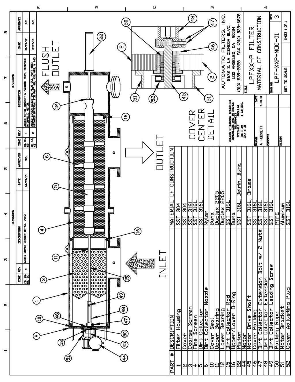
15 5.3 Problem: Frequent flushing during normal operation POSSIBLE CAUSE 1. Very dirty water. 2. Marginal working pressure results in poor cleaning cycle. 3. Screen may be partially plugged. 4. Dirt collector may be jammed which results in only cleaning the screen directly in front of the nozzles. SOLUTION 1. Screen opening size may be too small for the given application. Consult manufacturer. 2. Verify the inlet pressure is at least 15 PSI during the cleaning cycle. If not, partially close the outlet valve to increase inlet pressure. 3. Perform super flush as described in section Open filter and verify the dirt collector rotates freely. 5.4 Problem: Screen will not clean properly POSSIBLE CAUSE 1. The flush cycle duration is too short. 2. Filter was shut down dirty with contaminants caked on the screen. 3. Flush line is causing back pressure on the flush valve. 4. Piston is not operating properly. SOLUTION 1. Increase flush duration on controller panel. 2. Perform super flush as described in section Make sure the flush line is 1 larger than the flush valve (See section 2.2). 4. Verify that the indicator pin is moving to its full stroke during the cleaning cycle. Make sure that the inlet pressure is at least 15 PSI during the cleaning cycle. SECTION VI SPARE PARTS 6.1 Recommended Spare Parts The following are recommended spare parts to keep in stock: - Fine Screen (#4) - Set of O-rings (#16) - Cover Seal (#10) - Dirt Collector (#5) - Upper Bearing (#11) - Lower Bearing (#12) - D/P Switch (#34) - Controller Board - Piston Repair Kit (#29) - Dirt Collector Nozzles (#6) - Mini-Filter (#18) -Packing Rope (#50) 6.2 Spare Parts List Refer to filter cutaway on page
16 APPENDICES Appendix I Special Installation I. AUTOMATIC BY-PASS Sometimes it is necessary to have flow even when the filter is out off service for periodic maintenance. In this situation, it is recommended to create a by-pass. FILTER BY-PASS It is very simple to create a by-pass, especially for the online models. To do so, add an isolation valve on both the inlet and outlet and a bypass with another isolation valve (see drawing). If the by-pass valve is provided with an actuator, it can be converted into an automatic by-pass system by wiring them to the controller (see controller manual). Appendix II Alternate Flushing Methods There are several possible solutions if there is not enough pressure and/or flow to successfully achieve a backwash. For low flow installations with pressure greater than 15 PSI, proceed as follows: 1. The easiest method is to place an automatic valve (pressure sustaining valve) at the filter outlet. The valve will close when the filter is flushing. During the cleaning cycle, there would be no water available to the system and the full pump capacity will be used for the backwash filter. 13
17 2. The required extra flow can be obtained by means of an expansion tank installed directly upstream of the filter inlet. The expansion tank would contain water at operating pressure to supply to the filter during the cleaning cycle. 3. Another way to obtain supplemental flow is to add a water source to the inlet of the filter. The water source would be controlled with an actuated valve, opening during the cleaning cycle (see controller manual for wiring). Appendix III Piston Due to longer screens on larger filters, it is necessary to employ a piston for the cleaning mechanism. The piston is used to control the linear movement of the dirt collector during cleaning cycles. This enables the dirt collector to clean the entire surface area of the screen in a spiral-downward movement. At the end of the cleaning cycle, the flush valve closes and the solenoid valve returns to its deenergized position, thus the normal filtration process resumes. At the same time, the piston is pressurized, which pushes the dirt collector back into its original position, ready for the next cleaning cycle. Upon initial installation of the system, all seals within the piston may not be set in place. This may lead to water leaking from the piston, which is normal. In addition to protecting the piston, the PVC cover sleeve allows water leakage to be drained to a single location. After the system has been running for some time, the seals within the piston will set and the leakage will decrease or stop completely. The cover sleeve can also be slid back to expose the bolt holes and 14

18 piston indicating pin. The piston should be installed so that the piston indicating pin is facing the ground. Note: Some LPF models come with a different piston than what is pictured below. 15
19 16
20 17
21 18
22 19
23 20
24 21
25 22
26 23
To ensure proper installation, digital pictures with contact information to before startup.
 Check List for Optimal Filter Performance? There should be no back-pressure on the flush line. A 1 valve should have a 2 waste line, and 2 valve should have a 3 waste line. Do not use rubber hosing or
Tekleen LPF USERS AUTOMATIC FILTERS, INC. MANUAL
 AUTOMATIC FILTERS, INC. 2672 S. LA CIENEGA BLVD. LOS ANGELES, CA 90034 310 839 2828 800 336 1942 FAX 310 839 6878 www.tekleen.com info@tekleen.com Tekleen LPF USERS MANUAL Table of Contents SECTION I INTRODUCTION
Tekleen ABW USERS AUTOMATIC FILTERS, INC. MANUAL
 AUTOMATIC FILTERS, INC. 2672 S. LA CIENEGA BLVD. LOS ANGELES, CA 90034 310 839 2828 800 336 1942 FAX 310 839 6878 www.tekleen.com info@tekleen.com Tekleen ABW USERS MANUAL ABW USERS MANUAL AUTOMATIC FILTERS,
To ensure proper installation, digital pictures with contact information to before startup.
 Check List for Optimal Filter Performance [ ] There should be no back-pressure on the flush line. A 1 valve should have a 2 waste line, and 2 valve should have a 3 waste line. Do not use rubber hosing
AMIAD Automatic Filters
 AMIAD Automatic Filters Filtomat M100-6800 Series Models: M104XLP, M106XLP, M108LP, M110P Hydraulically-Controlled Serial number: Order number: Catalog number: Filtration degree: Tested by: Installation,
90 SERIES SELF CLEANING WATER FILTER OPERATION & MAINTENANCE MANUAL
 90 SERIES SEF CEANING WATER FITER OPERATION & MAINTENANCE MANUA CONTENTS Filter Basics Installation Requirements Flush ine Hydraulic Connections Hydraulic Piston Filter Performance Normal Operation Backwash
LAKOS AUTOMATIC SELF-CLEANING SCREEN FILTERS
 LAKOS AUTOMATIC SELF-CLEANING SCREEN FILTERS Low-maintenance, high-efficiency, high-flow screen filtration in a compact footprint APPLICATIONS Industrial Process cooling Chilled water Water treatment Flow
HTX-HTH SEPARATORS I&O MANUAL
 INSTALLATION OPERATIONS AND MAINTENANCE HTX-HTH SEPARATORS I&O MANUAL 1365 N. Clovis Avenue Fresno, California 93727 (559) 255-1601 www.lakos.com LS-714B (Rev. 11/17) TABLE OF CONTENTS Table of Contents...
Spin Klin 12" Super Flow
 Spin Klin 12" Super Flow w w w. a r k a l - f i l t e r s. c o m Galaxy Super Flow Spin Klin Battery Standard Automatic Backwash Operation and Maintenance Manual Filtration Process During filtration, water
Tekleen GB6 & GB7 USERS AUTOMATIC FILTERS, INC. MANUAL
 AUTOMATIC FILTERS, INC. 67 S. LA CIENEGA BLVD. LOS ANGELES, CA 90034 30 839 88 800 336 94 FAX 30 839 6878 www.tekleen.com info@tekleen.com Tekleen GB6 & GB7 USERS MANUAL GB6 & GB7 USERS MANUAL AUTOMATIC
Installation and Operation Instruction Manual FWINSMAN303. Yardney - Filtaworx FW06EX - FW10
 Installation and Operation Instruction Manual FWINSMAN303 Yardney - Filtaworx FW06EX - FW10 Phone: 951.656.6716 Toll-Free: 800.854.4788 www.yardneyfilters.com Yardney Water Management Systems, Inc. 6666
Operator's Manual. Models (¾") (1") (1½ ) (2 ) (3") (4") (6") (8")
 (1) (1½ ) (2 ) (3) (4) (6) (8)") OdisMatic Hydraulic Filter Series 851 Operator's Manual Models 85107 (¾") 85101 (1") 85115 (1½ ) 85102 (2 ) 85103 (3") 85104 (4") 85106 (6") 85108 (8") Content 1. Technical Specifications. 2. Materials.
OdisMatic Hydraulic Filter Series 851 Operator's Manual Models 85107 (¾") 85101 (1") 85115 (1½ ) 85102 (2 ) 85103 (3") 85104 (4") 85106 (6") 85108 (8") Content 1. Technical Specifications. 2. Materials.
I+ Series Operation & Maintenance Manual
 + Series peration & aintenance anual + Series peration & aintenance anual ontents Basics nstallation equirements ouplings lush ine ydraulic onnections ydraulic Piston Performance Normal peration Backwash
OPERATION AND PARTS MANUAL
 OPERATION AND PARTS MANUAL MODEL NUMBER : PART NUMBER : TAP- IN KIT 5100-5151 BAYNE MACHINE WORKS, INC. PHONE: (864) 288-3877 910 FORK SHOALS ROAD TOLL FREE: (800) 535-2671 GREENVILLE S.C., 29605 FAX:
ARKAL SCREEN LINE H - SERIES Hydraulically Operated Self-Cleaning Screen Filter SERVICE & MAINTENANCE MANUAL
 ARKAL SCREEN LINE H - SERIES Hydraulically Operated Self-Cleaning Screen Filter SERVICE & MAINTENANCE MANUAL Table of Contents Subject Page No. Introduction... 2 Safety Instructions... 3 Description &
3 Spin Klin Battery Operation and Maintenance Manual
 3 Spin Klin Battery Operation and Maintenance Manual Operation During the filtration stage, water flows through the INLET manifold and is distributed through the 3 x 2 backwash valves into the S.K. filters.
New Filtration Products from LAKOS
 New Filtration Products from LAKOS Disc Filters Screen Filters January 11, 2018 8:00 am Pacific Time Presented by: Randy Delenikos LAKOS Filtration Systems Randy.Delenikos@lakos.com Ver3.12/6/2017 Why
EJECTORS GENERAL OPERATION & MAINTENANCE MANUAL
 EJECTORS GENERAL OPERATION & MAINTENANCE MANUAL The information contained in this manual was current at the time of printing. The most current versions of all Hydro Instruments manuals can be found on
SST & PRO II Media Filtration Systems Installation and Operation Instructions
 SST & PRO II Media Filtration Systems Installation and Operation Instructions THIS MANUAL TO BE LEFT WITH THE END-USER LAKOS PRO II & SST Systems are available with an optional skid mount assembly. Consult
Ideal Installation. I & M Mark 67 (1/2 6 ) Control Line. Installation & Maintenance Instructions for Mark 67 Pressure Regulators
 Control Line. Installation & Maintenance Instructions for Mark 67 Pressure Regulators") I & M Mark (/ ) 0 Wasson Road Cincinnati, OH 0 USA Phone --00 Fax -8-00 info@richardsind.com www.jordanvalve.com Installation & Maintenance Instructions for Mark Pressure Regulators Warning: Jordan Valve
I & M Mark (/ ) 0 Wasson Road Cincinnati, OH 0 USA Phone --00 Fax -8-00 info@richardsind.com www.jordanvalve.com Installation & Maintenance Instructions for Mark Pressure Regulators Warning: Jordan Valve
Installation & Operation Instruction Manual FWINSMAN300. Yardney - Filtaworx FW02 - FW03
 Installation & Operation Instruction Manual FWINSMAN300 Yardney - Filtaworx FW02 - FW03 Phone: 951.656.6716 Toll-Free: 800.854.4788 www.yardneyfilters.com Yardney Water Management Systems, Inc. 6666 Box
APOLLO DISC-KLEEN FILTERS
 FILTRATION APOLLO DISCKLEEN FILTERS OPERATION, INSTALLATION & MAINTENANCE GUIDE ANGLE CONFIGURATION TWIN CONFIGURATION TABLE OF CONTENTS Specifications...3 Filter Dimensions... Water Quality & Maximum
INSTALLATION, OPERATION AND MAINTENANCE MANUAL (IOM)
") INSTALLATION, OPERATION AND MAINTENANCE MANUAL (IOM) IOM-1088 03-16 Model 1088 Vacu-Gard Blanketing Valve ISO Registered Company SECTION I I. DESCRIPTION AND SCOPE The Model 1088 Vacu-Gard is a tank blanketing
INSTALLATION, OPERATION AND MAINTENANCE MANUAL (IOM) IOM-1088 03-16 Model 1088 Vacu-Gard Blanketing Valve ISO Registered Company SECTION I I. DESCRIPTION AND SCOPE The Model 1088 Vacu-Gard is a tank blanketing
Aqua-Clear Fiberglass Sand Filters
 Aqua-Clear Fiberglass Sand Filters Addendum to the Installation & Users Guide Automatic Backwash Filter Assembly See Installation & User s Guide for important Safety Instructions System Contents... 3 Overview...
Check Valves Check Valves are the simplest form of directional control valves, but they can also be used as pressure controls.
 Check Valves Check Valves are the simplest form of directional control valves, but they can also be used as pressure controls. Standard Check Valve The standard check valve permits free flow in one direction
Installation and Operation Instruction Manual INSMAN-201. Industrial Multi Media Single Tank
 Installation and Operation Instruction Manual INSMAN-201 Industrial Multi Media Single Tank Phone: 951.656.6716 Toll-Free: 800.854.4788 www.yardneyfilters.com 1 Yardney Water Management Systems, Inc. 6666
SAND FILTERS. Models: ECSF500, ECSF650, ECSF700, & ECSF800
 SAND FILTERS Models: ECSF500, ECSF650, ECSF700, & ECSF800 FUNCTION The filter uses special filter media to remove dirt particles from pool water. The filter media is loaded into the filter tank and functions
GL Ludemann Y-Strainers
 GL Ludemann Y-Strainers Installation, Operation and Maintenance Manual English Issue 1-03/2014 - Page 1/7 GENERAL These instructions are for installing, operation and maintenance of Y-strainers fabricated
Sand Filtration System
 Sand Filtration System Owners Manual Installation, Operation, and Parts SHOW FILTRATION SYSTEM SAVE THIS INSTRUCTION MANUAL Note: Use only High Rate Sand No. 20 Silica Sand (.45mm -.55) specifically manufactured
PFA LINED BALL VALVES Installation, Operation and Maintenance Manual
 ACRIS PFA LINED BALL VALVES WWW.AMRESIST.COM Table of Contents Safety Instructions - Definition of Terms............................................2 Introduction..............................................................2
Steam/Water Washdown Units Safety and Operation Installation and Maintenance Instructions
 INSTALLATION AND MAINTENANCE INSTRUCTIONS IM-8-002-US October 2016 Steam/Water Washdown Units Safety and Operation Installation and Maintenance Instructions These instructions should be read by the Company
Crispin Valves Operating Guide. Crispin
 Crispin Valves Operating Guide Crispin Since 1905 Crispin Multiplex Manufacturing Co. 600 Fowler Avenue Berwick, PA 18603 1-800-AIR-VALV T: (570) 752-4524 F: (570) 752-4962 www.crispinvalve.com sales@crispinvalve.com
GENERAL PUMPA member of the Interpump Group
 FEATURES Innovative drive design eliminates need for auxiliary hydraulic drive HWB Series Hydraulic Drive - Triplex Plunger Pump HWB2512 & HWB2112 Forged brass manifold No scheduled maintenance required
INSTRUCTIONS. Fc. -1,<" SERIES ST-261 REGULATING UNLOADER VALVE
 INSTRUCTIONS Fc. -1,
INSTALLATION, OPERATION, AND MAINTENANCE MANUAL
 INSTALLATION, OPERATION, AND MAINTENANCE MANUAL MODEL 4D-200 REDUCED PRESSURE PRINCIPLE (RPZ) & MODEL 4D-700 REDUCED PRESSURE DETECTOR ASSEMBLY (RPDA) BACKFLOW PREVENTERS 2 ½ 10 Conbraco Industries Inc.
WARCO CHEMAG SERIES GH FILTERS
 WARCO CHEMAG SERIES GH FILTERS High Performance Pleated & Bag Type Filtration Systems INSTALLATION, OPERATION, AND MAINTENANCE INSTRUCTIONS Thank you for your purchase of a WARCO Series GH Filtration System.
INSTALLATION & SERVICE INSTRUCTION MANUAL W.A. KATES FLOW CONTROLLERS FC VALVE MODELS E THRU M
 INSTALLATION & SERVICE INSTRUCTION MANUAL W.A. KATES FLOW CONTROLLERS FC VALVE MODELS E THRU M IMPORTANT 1. W. A. Kates flow rate controllers are designed to accurately regulate flows and are precision
TECHNICAL DATA 1-1/2 (dn40)
") July 1, 2011 Deluge Valves 209a DESCRIPTION The Viking Model E-3 1-1/2 Deluge Valve is a quick-opening, differential type flood valve with a rolling diaphragm clapper. The deluge valve is used to control
July 1, 2011 Deluge Valves 209a DESCRIPTION The Viking Model E-3 1-1/2 Deluge Valve is a quick-opening, differential type flood valve with a rolling diaphragm clapper. The deluge valve is used to control
HWB Series GENERAL PUMP. Hydraulic Drive Triplex Plunger Pump INDUSTRIAL INDUSTRIAL FEATURES
 GENERAL PUMP HWB Series Hydraulic Drive Triplex Plunger Pump FEATURES INDUSTRIAL INDUSTRIAL Innovative drive design eliminates need for auxiliary hydraulic drive Forged brass manifold Built-in Pump Thermal
Installation And Operation Instruction Manual INSMAN-101. Sand Media Filters. Phone: Toll-Free:
 Installation And Operation Instruction Manual INSMAN-101 Sand Media Filters Phone: 951.656.6716 Toll-Free: 800.854.4788 www.yardneyfilters.com 1 Yardney Water Management Systems, Inc. 6666 Bo Springs Blvd.
PUMPS AND FILTRATION
 Rain Bird applies its industry leading irrigation expertise to the design and manufacture of pump stations and filtration products. By doing so, Rain Bird is the only irrigation manufacturer able to provide
ANDERSON GREENWOOD SERIES 500 PILOT OPERATED SAFETY RELIEF VALVES INSTALLATION AND MAINTENANCE INSTRUCTIONS
 Before installation these instructions must be fully read and understood TABLE OF CONTENTS 1. General valve description and start-up... 1 2. Main valve maintenance... 1 3. Pilot maintenance... 5 4. Pilot
DYNAFLUID 2000 STEAM & WATER MIXING VALVE INSTALLATION & OPERATING MANUAL
 DYNAFLUID 2000 STEAM & WATER MIXING VALVE INSTALLATION & OPERATING MANUAL LILLY ENGINEERING COMPANY 217 CATALPA STREET P.O. BOX 173 ITASCA, ILLINOIS 60143 630-773-2222 FAX: 630-773-3443 www.lillyengineering.com
DP3 Pump. 3:1, Air-operated, Oil. General. Operation. Technical Data. Installation R0 10/09. 35a 35b 35c
 DP3 Pump 3:1, Air-operated, Oil General The DP3 Pump is a compressed air-operated piston reciprocating medium pressure pump. Suitable for medium flow transfer of high viscosity lubricants and for oil delivery
DP556 Pump. 55:1, Air-operated, Grease. General. Operation. Technical Data. Installation. Mounting with Reinforced Cover (Recommended)
") DP556 Pump 55:1, Air-operated, Grease General The DP556 Pump is a compressed air-operated reciprocating piston pump. This high capacity demand pump is compatible with mineral and synthetic grease and suitable
DP556 Pump 55:1, Air-operated, Grease General The DP556 Pump is a compressed air-operated reciprocating piston pump. This high capacity demand pump is compatible with mineral and synthetic grease and suitable
F76 Water Filters. Specifications. and MV876 Automatic-Backwash Control Accessory (not included)
") F76 Water Filters and MV876 Automatic-Backwash Control Accessory (not included) The F76 is a high flow capacity water filter used to remove sediment and debris from residential or commercial water systems.
F76 Water Filters and MV876 Automatic-Backwash Control Accessory (not included) The F76 is a high flow capacity water filter used to remove sediment and debris from residential or commercial water systems.
HARMSCO Hurricane Swing Bolt Water Filters Models: HUR 1X170FL, HUR 3X170FL HUR 5X170FL, & HUR 8X170FL
 Models: HUR 1X170FL, HUR 3X170FL HUR 5X170FL, & HUR 8X170FL INSTALLATION AND OPERATION MANUAL HUR 8X170FL HUR 5X170FL HUR 3X170FL HUR 1X170FL Harmsco Filtration Products With Patented Up-Flow and Tangential/Rotational
Installation, Operation, and Maintenance Manual
 Installation, Operation, and Maintenance Manual API 6D Piston Check Valve - IOM: Installation, Operation and Maintenance Manual 1/16 Table of Contents 1 INTRODUCTION... 3 1.1 SCOPE... 3 1.2 DISCLAIMER...
Clean Water Made Easy
 Clean Water Made Easy http://www.cleanwaterstore.com Pro-OX 2510 Manual Backwash Iron Filter Installation & Start-Up Guide Thank you for purchasing a Clean Water System! With proper installation and a
BERMAD Waterworks. Pressure Relief/Sustaining Valve. Model: WW Series. Features and Benefits. Major Additional Features
 Pressure Relief/Sustaining Valve Prioritizing pressure zones Ensuring controlled pipeline fill-up Preventing pipeline emptying Pump overload & cavitation protection Safeguarding pump minimum flow Excessive
INSTALLATION, OPERATION, AND MAINTENANCE MANUAL WELKER AUTOMATIC INSERTION PROBE
 INSTALLATION, OPERATION, AND MAINTENANCE MANUAL WELKER AUTOMATIC INSERTION PROBE MODELS AIP-1 AIP-2 DRAWING NUMBERS AD198CA AD198CM AD198CO AD198DK.1 AD455BG AD455BO AD455EO MANUAL NUMBER IOM-006 REVISION
Pilot-Operated Regulators
 Fisher Controls Instruction Manual Type 1098-EGR & 1098H-EGR Pilot-Operated Regulators R May 1987 Form 5084 Contents Introduction................................... 2 Scope of Manual..............................
SERVICING INSTRUCTIONS
 TSP Series 66 Triplex Plunger Pump SERVICING INSTRUCTIONS TRIPLEX TRIPLEX SERVICING PUMP PROCEDURES Valve Replacement: All inlet and discharge valves can be serviced without disrupting the inlet or discharge
Manual for 12 Sand Filter/ Pump Combo Unit.
 Manual for 12 Sand Filter/ Pump Combo Unit. MODELS: CC2013/CC2015 SAFETY INFORMATION 1. The sand filters are designed to work with water at temperature>than 0 and
Thompson Strainer MLS-2
 Serial Number Location GENERAL SPECIFICATIONS: - Maximum Flow: GPM (No minimum flow requirement). - Maximum Pressure: 5 PSI (Higher pressure models available). - Not Designed for Suction / Vacuum. - Screen
Type 644 and 645 Differential Pressure Pump Governors
 Instruction Manual 644 and 645 Pump Governors Type 644 and 645 Differential Pressure Pump Governors Introduction Scope of Manual This instruction manual provides information on installation, adjustment,
Mounting and Operating Instructions EB 8135/8136 EN. Series V2001 Valves Type 3535 Three-way Valve for Heat Transfer Oil
 Series V2001 Valves Type 3535 Three-way Valve for Heat Transfer Oil Type 3535 Three-way Valve with bellows seal and rod-type yoke (partial view) Mounting and Operating Instructions EB 8135/8136 EN Edition
OPERATION AND PARTS MANUAL
 OPERATION AND PARTS MANUAL MODEL NUMBER : PART NUMBER : GTL 1110 1900-0510 SERIAL NUMBER : BAYNE MACHINE WORKS, INC. PHONE: (864) 288-3877 910 FORK SHOALS ROAD TOLL FREE: (800) 535-2671 GREENVILLE S.C.,
An Illustrated Manual: Constant Level Lubricators Function, Installation, and Features
 An Illustrated Manual: Constant Level Lubricators Function, Installation, and Features Constant Level Lubricators Table of Contents Overview Typical Applications and Industries..........................
W91/W94 Series TEMPERATURE REGULATORS. Self-Operated Temperature Regulators. Design & Operation W91 Non-Indicating W94 Dial Thermometer
 Design & Operation W91 Non-Indicating W94 Dial Thermometer Watson McDaniel reserves the right to change the designs and/or materials of its products without notice. 2010 Watson McDaniel Company CAPILLARY
Instructions for Installation, Operation, Care and Maintenance
 Bulletin 407 Rev. T Model E Alarm Check Valve Bulletin 407 Rev. T Instructions for Installation, Operation, Care and Maintenance 4 (100 mm), 6 (150 mm), 8 (200 mm) Sizes With Model E3 Trim Listed by Underwriters
Pressurized Bead Filters
 Pressurized Bead Filters Installation Instructions Table of Contents Safety Information Installation Assembly Start Up Maintenance Troubleshooting Warranty Safety Information: 1. Installation should be
TECHNICAL DATA. Trimpac 244a. April 15, 2011
 April 15, 2011 Trimpac 244a 1. DEsCrIpTION DESCRIPTION TRIMPAC Model B-1 and B-1B is a factory-assembled trim package with an electric release module in a metal enclosure. The standard trim normally required
Congratulations PRE-OPERATION SETUP
 Congratulations on the purchase of your new ProVac Industrial Pumpout Station. Your new ProVac has been manufactured with the best quality components to give you year after year of trouble free service.
Operation and Maintenance of Mechanical Self-Cleaning Filters. Maynard King CB Tubecraft div of K&D Pratt
 Operation and Maintenance of Mechanical Self-Cleaning Filters Maynard King CB Tubecraft div of K&D Pratt Filtration Terms Filter Area The total area of a filter element, usually expressed in square inches
TECHNICAL DATA. Viking Technical Data may be found on Style: 90 Degree Pattern (inlet to outlet)
") Flow Control 500a DESCRIPTION The Viking 1-1/2 is a quick opening, differential type flood valve with a spring loaded rolling diaphragm clapper. The can be used to facilitate manual or automatic on/off
Flow Control 500a DESCRIPTION The Viking 1-1/2 is a quick opening, differential type flood valve with a spring loaded rolling diaphragm clapper. The can be used to facilitate manual or automatic on/off
Welker Sampler. Installation, Operation, & Maintenance Manual. Model GSS-4HP
 Installation, Operation, & Maintenance Manual Welker Sampler Model GSS-4HP The information in this manual has been carefully checked for accuracy and is intended to be used as a guide to operations. Correct
Filtomat M100/MG Filters
 Filtomat M100/MG Filters Hydraulic self-cleaning screen filters, with no external power source required flow rates M100: up to 400 m 3 /h (1,760 gpm) MG: up to 800 m 3 /h (3,520 gpm) minimum operating
Installation Instructions
 Installation Instructions SELECTRONIC PROXIMITY TOILET CONCEALED FLUSH VALVE. &. GPF Certified to comply with ASME A..M 00 AS America, Inc. Concealed Flushometer for -/" Top or Back Spud Bowls MODEL NUMBERS
Welker Automatic Insertion Diffusing Probe Model AIP-3DP
 Installation, Operation, and Maintenance Manual Welker Automatic Insertion Diffusing Probe Model AIP-3DP The information in this manual has been carefully checked for accuracy and is intended to be used
36-1 DP PLEASE READ BEFORE USING THIS EQUIPMENT
 36-1 DP PLEASE READ BEFORE USING THIS EQUIPMENT DP 36-1 Assembly Instructions PLEASE READ INSTRUCTIONS COMPLETELY BEFORE STARTING We thank you for purchasing the DP-36 pressure system. This system has
Technical Information
 Technical Information Installation, Operation, Installation, Operation and Maintenance and Maintenance Manual Manual Balston Series "SR" Steam Filters USFDA, USDA, and 3A Compliance Balston SR Steam Filters
Flow Control & Pressure Reducing Valve with Hydraulic Control (Sizes 3''- 12"; DN80-DN300)
") IOM IR-472-50-bRU Flow Control & Pressure Reducing Valve with Hydraulic Control (Sizes 3''- 12"; DN80-DN300) Description: The BERMAD Flow Control and Pressure Reducing Valve with Hydraulic Control is a
IOM IR-472-50-bRU Flow Control & Pressure Reducing Valve with Hydraulic Control (Sizes 3''- 12"; DN80-DN300) Description: The BERMAD Flow Control and Pressure Reducing Valve with Hydraulic Control is a
APT10-2 Automatic Pump Trap
 6120050/3 IM-P612-18 ST Issue 3 APT10-2 Automatic Pump Trap Installation and Maintenance Instructions 1. General safety information 2. Product information 3. Installation Closed loop steam systems only
AIR CLEANERS Model MC 3000 OWNER S MANUAL CAUTION Read complete instructions before operating. Please file for future reference.
 AIR CLEANERS Model MC 3000 OWNER S MANUAL CAUTION Read complete instructions before operating. Please file for future reference. MODEL MC 3000 SPECIFICATION Input Volts: 208-230/430 VAC, 60Hz, 3 Phase
OPERATION AND PARTS MANUAL
 OPERATION AND PARTS MANUAL MODEL NUMBER : PART NUMBER : DTL 1116 1900-0098 SERIAL NUMBER : BAYNE MACHINE WORKS, INC. PHONE: 864.288.3877 910 FORK SHOALS ROAD TOLL FREE: 800.535.2671 GREENVILLE SC, 29605
Pneumatic High-Viscosity Filtration System Instruction Manual
 Pneumatic High-Viscosity Filtration System Instruction Manual P/N: 61512 05/17 1 2 Pneumatic High Viscosity Filtration Systems PN: 61512 14 April, 2009 rev A 36933 Pneumatic Hand Cart HV Filtration System
26 Series Stainless Steel 2-way Ball Valves
 1-800-899-0553 26 Series Stainless Steel 2-way Ball Valves Users Manual Installation, Operation, & Maintenance 1. General Precaution 1.1. Material Section Material deterioration is determined by the contained
TECHNICAL DATA. Inlet Type Outlet Type OBSOLETE 6 (DN150)
") January 13, 2006 Deluge Valves 211 a 1. PRODUCT NAME Viking Model E-1 Deluge Valve 3 (DN80) Available since 1985 4 (DN100) Available since 1985 6 (DN150) Available since 1984 2. MANUFACTURER THE VIKING
January 13, 2006 Deluge Valves 211 a 1. PRODUCT NAME Viking Model E-1 Deluge Valve 3 (DN80) Available since 1985 4 (DN100) Available since 1985 6 (DN150) Available since 1984 2. MANUFACTURER THE VIKING
Model DV-5 Deluge Valve, Diaphragm Style, 1-1/2 thru 8 Inch (DN40 thru DN200), Deluge System Electric Actuation
, Deluge System Electric Actuation") Deluge Valve DV-5 Model DV-5 Deluge Valve, Diaphragm Style, 1-1/2 thru 8 Inch (DN40 thru DN200), Deluge System Electric Actuation GeneralDescription The Model DV-5 Deluge Valve (described in Technical
Deluge Valve DV-5 Model DV-5 Deluge Valve, Diaphragm Style, 1-1/2 thru 8 Inch (DN40 thru DN200), Deluge System Electric Actuation GeneralDescription The Model DV-5 Deluge Valve (described in Technical
PRESSURE RELIEF VALVE
 PRESSURE RELIEF VALVE INSTRUCTIONS Installation - Operation - Inspection - Maintenance 4" - 36" MODEL 50RWR Pressure Relief Valve Globe Flat Seat Style ROSS VALVE Mfg. Co., Inc. PO BOX 595, TROY, NY 12181
Hydraulics. Part B, Section 1. This section covers the following unit configurations. 3700V 3800V 3900V
 Part B, Section 1 Model Voltage Pump Manifold Control This section covers the following unit configurations. 3500V 3700V 3800V 3900V All Piston (F) 4-Port (A) 6-Port (B or C) -Port (S or T) Vista Standard
Introduction. Installation. Maintenance. Bill of Materials
 Table of Contents Introduction Specitications... 3 Operation... 4 Installation New Installations... 6 Retrofit Installations... 6 Flow Control Switch... 7 Dimensions... 8 E-7 Valve... 28 E-7 Valve with
Table of Contents Illustrations
 Principals of Operation Inspection & Troubleshooting Principles of Operation Inspection & Troubleshooting Form No. F 1031 Section 1000 Issue Date 09/19/94 Rev. Date 02/07/07 Table of Contents Illustrations
INSTALLATION INSTRUCTIONS FOR THE TRUCK MOUNTED VIPER ADDITIVE INJECTION SYSTEM GTP-8776C
 INSTALLATION INSTRUCTIONS FOR THE TRUCK MOUNTED VIPER ADDITIVE INJECTION SYSTEM GTP-8776C This additive injection system was designed to be used with five gallon jug of additive. The system is supplied
AIRGO MISTING SYSTEM MAINTENANCE
 AIRGO MISTING SYSTEM MAINTENANCE WARNING: Disconnect the fan and misting pump from power before servicing. Service schedule Schedule Procedure 50 hours of operation Initial oil change 300 hours of operation,500
Orenco Automatic Distributing Valve Assemblies
 This article may describe design criteria that was in effect at the time the article was written. FOR CURRENT DESIGN CRITERIA, call Orenco Systems, Inc. at 1-800-348-9843. Orenco Automatic Distributing
OPERATION AND PARTS MANUAL
 OPERATION AND PARTS MANUAL MODEL NUMBER : PART NUMBER : Revolution 1999-0500 SERIAL NUMBER : BAYNE MACHINE WORKS, INC. PHONE: 864.288.3877 910 FORK SHOALS ROAD TOLL FREE: 800.535.2671 GREENVILLE SC, 29605
PV4 - Compact Shut Off Style Pig Valve IOM - Installation, Operation & Maintenance
 ACECO Valve P.O. Box 9 Mounds, Oklahoma 74047 PV4 - Compact Shut Off Style Pig Valve IOM - Installation, Operation & Maintenance Doc. No.: IOM-PV4-.0 Date: 6/0-00 Revision: A Contents: Installation Operation
1/2" AIR DRIVEN DIAPHRAGM PUMP
 1/2" DRIVEN DIAPHRAGM PUMP OPERATION AND SERVICE GUIDE O-1225D NOV. 2008 Page 1 of 6 Refer to Bulletin P-605, Parts List P-9151 DRIVEN, DOUBLE DIAPHRAGM PUMP MANUAL Congratulations on purchasing one of
OPERATION AND PARTS MANUAL
 OPERATION AND PARTS MANUAL MODEL NUMBER : PART NUMBER : BTL 208-12 1999-0212 SERIAL NUMBER : BAYNE MACHINE WORKS, INC. PHONE: 864.288.3877 910 FORK SHOALS ROAD TOLL FREE: 800.535.2671 GREENVILLE SC, 29605
APT14 Automatic Pump Trap Installation and Maintenance Instructions
 6120250/7 IM-P612-04 ST Issue 7 APT14 Automatic Pump Trap Installation and Maintenance Instructions 1 Product information 2 Operation 3 Installation Closed loop steam systems only 4 Commissioning 5 Maintenance
Operation and Maintenance Manual
 BM / BMA Hydrometers ½ Operation and Maintenance Manual i This manual is intended for use by the users of this equipment. The information contained herein is the property of the Arad Ltd. Dalia and may
RAIN BIRD - AQUAGATOR AQUAGATOR INSTALLATION & TROUBLESHOOTING MANUAL
 AQUAGATOR INSTALLATION & TROUBLESHOOTING MANUAL Cozz GT27069-A Revised July 2002 P/N 632360 AQUAGATOR TABLE of CONTENTS DESCRIPTION PAGE INTRODUCTION....... 1 SECTION 1 - PRE-INSTALLATION REQUIREMENTS.
Fluid Maintenance. The hydraulic oil performs four functions in the hydraulic system:
 The hydraulic oil performs four functions in the hydraulic system: Transmits Energy Coolant Lubricant Sealant Viscosity Viscosity is the rating of the oil thickness or resistance to flow. Viscosity is
Figure 1.1. From left to right: PVC, GRP and AISI 316L. Filter type Filter body material Max pressure Max temperature BSP PVC 150 psig 104 F, 40 C
 1. The filter body The filter bodies come in three different materials: PVC (PolyVinyl Chloride), AISI 316L (stainless steel) and GRP (Glass-fiber Reinforced Polyester). Filter bodies in PVC and GRP have
SINGLE ACTING ALTITUDE VALVE
 SINGLE ACTING ALTITUDE VALVE INSTRUCTIONS Installation - Operation - Inspection - Maintenance 4" - 36" ROSS MODEL - 40AWR THROTTLING, SINGLE ACTING ALTITUDE VALVE Globe Flat Seat Style ROSS VALVE Mfg.
back to main page Type: Butterfly valves Instructions and Operation Manual Warning! Warning! Danger for life! 1. Intended use Danger for life!
 Instructions and operation manual for butterfly valves This manual is intended to support the users of Herberholz butterfly valves type HRD/HRA, RD/RA, LDKE/LDKF for installation, operation and maintenance
M300 Filters. Versatile and efficient self cleaning hydraulic filters that require no external power source
 M300 Filters Versatile and efficient self cleaning hydraulic filters that require no external power source flow rates filtration degrees water for cleaning minimum operating pressure up to 4840 US gpm
0.7 m 3 /h - 3 GPM D 07 RE 125 D 07 RE 5. owner s manual
 0.7 m 3 /h - 3 GPM D 07 RE 125 D 07 RE 5 owner s manual GB You have just become the owner of one of the latest in the line of DOSATRON proportional dosing pumps and we congratulate you on your choice.