HYDRAULIC KIT INSTRUCTIONS FOR GM - MUNCIE
|
|
|
- Sydney Chase
- 5 years ago
- Views:
Transcription


1 HYDRAULIC KIT INSTRUCTIONS FOR GM - MUNCIE BEFORE INSTALLING TRANSMISSION IN CAR, YOU MUST CHECK THE HYDRAULIC BEARING CUSHION MEASUREMENT!!! SEE PAGE 7 OF INSTALLATION MANUAL FOR INSTRUCTIONS ON MEASURING HYDRAULIC BEARING CUSHION. RECORD THIS MEASUREMENT FOR FUTURE REFERENCE.
 and is to be used by SST customers or their authorized installers for the sole purpose of installing")

 and it is designed to be in constant contact with the pressure plate fingers.")
2 DAMAGE WILL OCCUR IF THIS MEASUREMENT IS INCORRECT!!! The material herein is the intellectual property of Silver Sport Transmissions ( SST ) and is to be used by SST customers or their authorized installers for the sole purpose of installing SST-supplied transmissions and related parts. Under no circumstances shall the manual or any portion thereof be copied, duplicated, distributed or incorporated in any written or printed document without the express written approval of Silver Sport Transmissions. SYSTEM DESCRIPTION: This system uses a firewall-mounted hydraulic master cylinder with remote reservoir and a combination slave cylinder/release bearing assembly. This combination bearing is called a concentric slave cylinder (CSC) and it is designed to be in constant contact with the pressure plate fingers. The CSC is compressed by the pressure plate fingers when at rest. When the clutch pedal is depressed, the master cylinder forces fluid into the CSC, causing it to expand and depress the pressure plate fingers, thereby releasing the clutch. This system is designed to use DOT 4 brake fluid. DO NOT use DOT 5 brake fluid! The seals in this system are not compatible with DOT 5 fluid, and will be ruined on contact with it. For higher temperature applications or if heat-related issues arise, the use of ATE Super Blue DOT 4 fluid is recommended. This system is engineered for use with a diaphragm-style pressure plate and is NOT This compatible system is engineered with most for three-finger use with a diaphragm-style pressure plates. pressure plate and is not compatible with some It is recommended three-finger style that pressure you remove plates. the over-center It is recommended spring (if that equipped) you remove from the overcenter pedal spring when (if equipped) using a diaphragm-style from the clutch pressure pedal when plate. using a diaphragm-style pressure clutch plate. KIT CONTENTS Please confirm that all parts have been received. The parts contained in your Master Cylinder kit are car-specific, and are listed on your Master Cylinder packing list. The parts contained in your Slave Cylinder kit are: Front bearing retainer with anti-rotation pin Combination slave cylinder/release bearing Braided steel hose with bleeder 3/8-16 socket head cap screws (4) DISASSEMBLY Remove original clutch linkages, transmission and bellhousing components: Fork push rod, clutch pedal push rod assembly Z-bar retaining clip, Z-bar, ball stud and bracket assembly Fork boot Drive shaft Shifter Handle and Shift Mechanism (if 3 or 4 speed equipped) Transmission and bellhousing Throw-out bearing, clutch fork and fork pivot 2

 of the brake master cylinder or brake booster mount, near the steering column.")
.")

3 MASTER CYLINDER MOUNTING 1. From under the hood, locate the factory clutch pushrod hole. On automatic cars, this may be a hole with a rubber grommet or a small sheet metal cover with two screws. On some cars, it is part of the steering column opening in the firewall. If there is a cover over an existing hole, remove the cover. Some vehicles may not have a factory hole in the firewall, but there should be a spot that is contoured for a hole. That spot is usually located below and slightly to the left (driver s side) of the brake master cylinder or brake booster mount, near the steering column. NOTE: On Chevrolet cars, the pushrod hole is to the right (passenger side) of the brake master cylinder. 2. If no clutch rod hole exists in your firewall, measure the diameter of the pushrod hole in the clutch master cylinder mounting block (the side that is against the firewall). Cut a hole of that size in the factory spot on the firewall. Some cars may require elongating the hole due to the angle of the master cylinder. 3. From the engine compartment, insert the master cylinder pushrod through the firewall and center the master cylinder pushrod in the hole, keeping the mount block against the firewall. Confirm that the pushrod points toward and reaches the clutch pedal attachment point (see PEDAL ATTACHMENT section). NOTE: Corvettes require that the master cylinder be rotated so that the ports on the top are pointed slightly towards the driver s side in order for the pushrod to be aligned with the clutch pedal. Carefully mark the firewall for each of the mounting bolt holes using a transfer punch, center punch or marker. 4. Drill a 3/8 diameter hole through the firewall for each marked location. Remove burrs. 5. Assemble mount block gasket to mount block, then set the master cylinder and mount block assembly to the firewall. See diagram on following page. Assemble 5/16-18 bolts through the assembly and firewall. On some applications it will be necessary to insert one or more bolts (usually the bottom bolt) from the passenger compartment side of the firewall. 6. From passenger compartment, assemble backing plate, lock washer and nuts. Align master cylinder, then tighten bolts to 25 ft-lb. NOTE: Chevrolet cars may require shimming due to firewall curvature. Shimming should result in smooth action of the master cylinder pushrod into the master cylinder. 7. Assemble the 90 end of the braided steel line to master cylinder port closest to firewall. 8. Assemble barb fitting to master cylinder at port located furthest from firewall. Use caution not to over tighten and break fittings. CAMARO/FIREBIRD BEFORE INSTALLATION CHEVELLE BEFORE INSTALLATION C1 VETTE 3


4 CAMARO/FIREBIRD CHEVELLE C2 VETTE Typical Master Cylinder Assembly: LINE FROM RESERVOIR ADJUST TO CORRECT PEDAL POSITION LINE TO CLUTCH SLAVE CYLINDER MASTER CYLINDER BACKING PLATE ATTACH TO CLUTCH PEDAL MOUNTING BLOCK GASKET FIREWALL 4


5 FLUID RESERVOIR MOUNTING 1. Remove the studs or nuts on the left hand (driver) side of the brake master cylinder. 2. Place reservoir bracket over the two holes or studs in the brake master cylinder, replace the original studs or nuts and tighten completely. Alternatively, the reservoir may be attached directly to firewall. 3. Assemble reservoir to the bracket using hardware supplied (part # CAA-PACK A). SLAVE CYLINDER MOUNTING NOTE: This procedure involves removal of the transmission s front bearing retainer and replacement with SST s custom bearing retainer. Please take care during the procedure to keep your work environment as clean as possible. 1. Remove four (4) bolts holding the front bearing retainer to the transmission (FIG. A). 2. Remove the front bearing retainer by tapping lightly with a mallet to break it free. 3. Remove gasket and thoroughly clean mating surface (FIG. B). 4. Apply small bead of RTV Silicone Gasket Maker (PERMATEX Ultra Grey or equivalent) to mounting face of bearing retainer as shown (FIG. C). Be sure not to apply excessive sealer near the oil slot area to prevent blocking the front bearing oil feed hole in the face of the transmission case. 5. Place the bearing retainer on the transmission ensuring that the oil slot located at 7 o clock lines up with the oil galley hole in case and that the dowel pin is positioned at the top (FIG. E). 6. Attach the bearing retainer to the transmission using (4) socket head cap screws. Apply Teflon sealant to threads of bolts (FIG. D). Torque the bolts to ft-lb in an X pattern. 7. Slide Concentric Slave Cylinder (CSC) over input shaft and dowel pin (FIG. F). 8. Make sure the CSC is positioned so that the hydraulic inlet points towards the fork opening in your bellhousing. You will only use the 1 ear located at the top for the dowel pin to pass through, the second and third ears are not used. 9. Continue with the remainder of your hydraulic clutch kit installation. 5

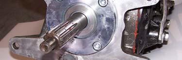
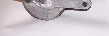
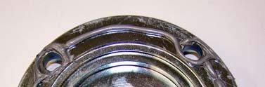
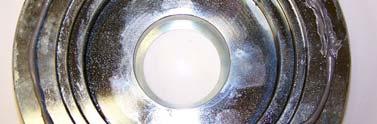
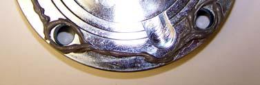
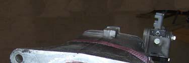
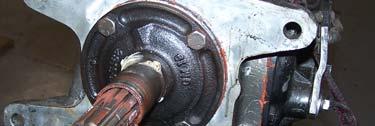
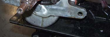
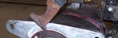
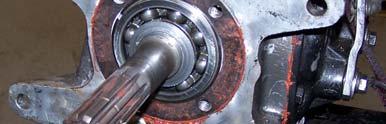
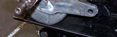

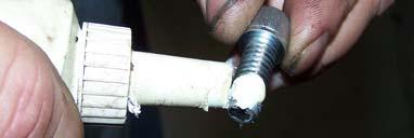

6 FIG. A REMOVE RETAINER/BOLTS FIG. B REMOVE OLD GASKET FIG. C APPLY RTV GASKET MAKER FIG. D APPLY THREAD SEALANT OIL SLOT FIG. E INSTALL BEARING RETAINER DOWEL PIN FIG. F INSTALL CSC 6

7 HYDRAULIC BEARING CUSHION CHECK The CSC is designed to be compressed ½ or more by the pressure plate fingers at rest. The CSC needs a minimum of 1/8 extra room to allow for clutch disc wear and expansion from heat. Clutch slippage will result if the CSC bottoms out and is partially depressing the pressure plate fingers at rest. The CSC cushion measurement procedure below tells you how far the CSC is away from being completely bottomed out. The acceptable range for CSC cushion is between 1/8 (0.125 ) and 3/8 (0.375 ). 1. With the correct clutch pressure plate and clutch disc mounted and torqued to the flywheel, install the bellhousing to the engine. 2. Use a straight edge and a steel rule to measure from the transmission mounting face of the bellhousing to the surface of the clutch fingers that contacts the release bearing. Record this depth measurement ( X ) (FIG. K). FIG. K 3. Your depth measurement above ( X ) minus 2.52 (about 2-17/32 ) gives you the cushion measurement: ( X ) 2.52 = CUSHION 4. The resulting cushion dimension should be between 1/8 (0.125 ) and 3/8 (0.375 ), with ¼ (0.250 ) being the ideal nominal cushion. If your cushion is not within this 1/8-3/8 range, first confirm the accuracy of the measurements. If still not within this range call Silver Sport Transmissions to obtain spacers to achieve the correct cushion. TRANSMISSION MOUNTING 1. Remove bellhousing from engine and install bellhousing to transmission. Tighten bolts only lightly at this time. 2. Install black rubber fork hole boot onto the end of the braided steel line that has the bleeder screw on it. Insert that end of the line through the bellhousing fork hole and attach braided steel line to CSC. Test-fit the line following the angle of the threads, not the angle of the machined face (see photos on the next page). NOTE: Be very careful not to cross-thread the fitting. 7


8 The line is designed for the bleeder screw to point downwards in order to reduce the chance of brake fluid getting on painted surfaces on your car during the bleeding process. 3. Verify the braided steel line is towards the back of the bellhousing and away from rotating components. 4. The transmission, bellhousing and hydraulic throw-out bearing are installed as a unit to the engine. HYDRAULIC LOW PRESSURE HOSE MOUNTING 1. Run the rubber supply hose from the bottom of the reservoir nipple to the barb fitting in the clutch master cylinder, and determine the exact length for the supply hose. The hose should be neither tight nor excessively loose, and should clear all moving steering gear and exhaust components. Take care to prevent foreign debris from entering hose. 2. Cut the line to desired length, ensure that no foreign matter is in the hose, then loosely assemble hose clamps. 3. Install hose to the master cylinder, then to the reservoir. When installing hose to the reservoir, hold the top of the reservoir to prevent overloading and damaging the mounting ears. HYDRAULIC HIGH PRESSURE HOSE MOUNTING 1. After bolting the transmission/bellhousing unit to the engine, attach the remaining end of the braided steel line to the clutch master cylinder and tighten. Use caution not to over tighten and break the fitting. 2. Final tighten all transmission mounting bolts (4 pcs). 3. Inspect the supply line inside bellhousing and confirm the hoses have ample clearance to the rotating clutch plate. It is extremely important that the hydraulic clutch hose DOES NOT come into contact with the clutch plate, as serious damage could result. NOTE: DOT 4 BRAKE FLUID REQUIRED. SHIELD HYDRAULIC LINES FROM HEAT, ESPECIALLY NEAR EXHAUST HEADERS. 8


9 PEDAL ATTACHMENT NOTE: If you are changing from a three (3) finger style pressure plate to a diaphragm style pressure plate you should also remove the clutch pedal over center spring, if equipped with one. Failure to remove the over center spring could result in the spring holding the clutch pedal down during normal operation. The over center spring will also tend to hold the pedal down while performing the bleeding operation with both the three finger and diaphragm style clutches during bleeding until the system is bled enough to return the pedal. An over center spring is not recommended for use with a diaphragm-style clutch, and the hydraulic system is not compatible with some three-finger style clutches. Shoulder Bolt Attachment (uses part # CAA-PACK F) 1. If there are two possible attachment holes in your clutch pedal arm, use the hole that best lines up with the pushrod coming out of the master cylinder. NOTE: Chevrolet master cylinder pushrod attaches to the rod lever on the passenger side of the steering column. 2. Adjust heim rod end position to achieve proper pedal height with master cylinder clutch push rod extended to its upper internal stop. If the master cylinder is not at its internal stop position when the pedal is at rest, the master cylinder vent/fill port could be blocked, preventing successful bleeding of the system. Make sure the pushrod travels in and out of the master cylinder in a nearly straight line and does not contact the firewall, mount block, or backing plate at any point during its travel. When desired pedal height is achieved, tighten locknut on pushrod. 3. Assemble shoulder bolt through heim joint of master cylinder pushrod. 4. Assemble plastic spacer, if needed, to shoulder bolt, in between heim joint and clutch pedal, then assemble to clutch pedal. Attach with washer and lock nut. Tighten to 20 ft-lb. NOTE: You may have to loosen the brake light switch bracket to insert the bolt. In some applications, a small adjustment of the switch position may be required to clear the bolt head. Clevis-type Attachment DO NOT pump the pedal until fluid is added to the reservoir. USE ONLY DOT 4 BRAKE FLUID. 1. Adjust rod end position to achieve pedal in home position with clutch push rod fully extended. When desired position is achieved, tighten locknut on pushrod. 2. Install rod end, flat washer, then spring clip retainer or cotter pin. SHOULDER BOLT TYPE CLEVIS TYPE 9
10 HYDRAULIC FLUID FILL & BLEED You will need two people to bleed this clutch system. Use caution to prevent brake fluid from contacting paint, as damage will likely occur. If your vehicle has an over-center spring installed, it will tend to hold the clutch pedal to the floor until the system is bled enough to return the pedal itself. Remove reservoir cap and baffle from the reservoir. 1. Fill the reservoir full with DOT 4 brake fluid. During the next steps check regularly to make sure that the reservoir does not run out of fluid. If this happens you will have to start the process over. 2. Open the bleeder screw to allow air to escape from the system. Give the fluid a few minutes to make its way down to the bleeder screw. Allow fluid to drip from the bleeder screw into a suitable container. Don t forget to keep fluid in the reservoir! 3. When the drip becomes a steady stream, close the bleeder screw. Refill the fluid reservoir. Open the bleeder screw slightly and have your helper depress the pedal. Close the bleeder as soon as the pedal reaches the floor. Then have your helper release the pedal. The pedal may need to be manually pulled up from the floor during these steps. Repeat this process several times, refilling the reservoir every 3 strokes or so. 4. When the bleeder stops spitting air, close and tighten the bleeder screw. Pump the pedal several times to check for proper feel. Repeat the process if the pedal is not firm throughout its travel, or if it seems that the clutch is not releasing fully. Make sure that the master cylinder pushrod is traveling its full stroke of 1.4 and that the master cylinder is fully extended when the clutch pedal returns to its home position. 5. If bleeding proves difficult for one reason or another, a manual vacuum bleeder can be used to draw a vacuum on the reservoir and thereby the entire system and pull trapped air into the reservoir. With the rubber baffle removed from the reservoir and the cap installed, apply vacuum to the vent hole in the center of the cap. You may try stroking the pedal while vacuum is being applied. Repeat until the system is bled. It may be necessary to prime the master cylinder by removing the high pressure hose at the master cylinder and block the fitting outlet to draw fluid into the cylinder when stroking the pedal. When the cylinder is primed, reattach the pressure line and continue the bleeding procedure. Take care not to spill brake fluid on any painted surfaces. 6. Upon successful bleeding, fluid level will need to be lowered to approximately 1/3 full. Excess fluid may be removed from the reservoir by siphoning with a hand-held vacuum pump or with a spoon or medicine cup. Reinstall baffle and cap. 7. Inspect for leaks, and replace the bellhousing inspection cover. 8. Check fluid level and add if necessary after the first test drive or after vehicle sits overnight. NOTE: It may be necessary to bleed the clutch again after minimal use, as operation may dislodge some trapped air. 10
11 INSPECTION AND TESTING USE EXTREME CAUTION WHEN TESTING YOUR CLUTCH RELEASE SYSTEM. DO NOT TEST IN HIGH TRAFFIC OR PUBLIC AREAS. ENGINE-OFF TEST Parking brake set, test the release and engagement of the clutch mechanism. Check for the following: 1. Clutch pedal completely up at its home position when released, and that the master cylinder pushrod is fully extended when the pedal is all the way up. 2. Clutch pedal does not hit brake lamp bracket or other bracket. 3. Low resistance for initial travel when depressing clutch pedal. Clutch resistance increasing at 1/3 of full stroke and remaining approximately constant through full travel to the floor. 4. Clutch pedal travel to floor without over-travel of clutch plate. Over-travel is characterized by a sudden hard pedal. This should not be a problem if the Hydraulic Bearing Clearance Check was accurately made. NOTE: The hydraulic slave cylinder has approximately 7/8 inch total stroke, minus the free play that was measured earlier. Most clutches release within 1/2 inch travel. 5. Smooth system operation with no abnormal noises. ENGINE-ON TEST: Hold brake, place transmission in neutral, start engine. Achieve idle of 1000 rpm or less. 1. Depress clutch pedal. 2. Ease shifter into gear. CAUTION: If transmission gears start to grind, pull back to neutral and stop engine. Repeat bleeding process. 3. Slowly release clutch pedal while maintaining brake pedal pressure. Confirm engine is being loaded as clutch pedal is released. 4. Repeat test step 1-3 through all gears, including reverse. NOTE: Reverse is not synchronized, and grinding may occur. This can be eliminated through placing shifter in forward gear immediately before proceeding to reverse gear setting. 11
12 CARE AND MAINTENANCE Your SST hydraulic clutch actuator system is designed to give you years of trouble-free service. In order to maximize the life of the system: Periodically check fluid level, hose clamps and hoses for damage. Flush the hydraulic fluid every 2 years with new, clean DOT 4 brake fluid. SYSTEM SPECIFICATIONS Master cylinder: Bore = Stroke = CSC: Stroke =.910 Fluid: DOT 4 brake fluid required. DO NOT USE DOT 5 FLUID. ACCESSORY ITEMS The following accessory items will enhance your installation: SST Cast Titanium-Aluminum Bellhousing. New casting features super high strength aircraft alloy, lightweight 15lbs, precision CNC machining for accurate alignment of transmission to crank bore, 168 tooth flywheel mounting. For both 4 & 5 speeds. Clutches/Flywheels We carry a full range of clutches, and both billet steel and aluminum flywheels. SST Reproduction Pedal Assemblies New precision made pedal conversion allow easy conversion from automatic, or quality replacement parts for restoration. SHIFTER HANDLES & MECHANISM Full line of 4 & 5 speed shifter handles and shift balls. CONTACT INFORMATION SILVER SPORT TRANSMISSIONS 2250 STOCK CREEK BOULEVARD ROCKFORD, TENNESSEE Phone: (865) Toll Free: (888) Fax: (865) SILVER SPORT TRANSMISSIONS IS DEDICATED TO YOUR SATISFACTION AND ENJOYMENT OF THIS PRODUCT. PLEASE SEND US PICTURES OF YOUR CAR ALONG WITH A TESTIMONIAL OF HOW YOU RATE THIS PRODUCT. WE WILL BE POSTING MANY CUSTOMER FEEDBACK LETTERS AND PICTURES ON OUR WEBSITE AND BROCHURES. ENJOY YOUR SILVER SPORT TRANSMISSION SYSTEM! 12
GM C10 TRUCK HYDRAULIC MOUNT INSTALLATION INSTRUCTIONS
 GM C10 TRUCK HYDRAULIC MOUNT INSTALLATION INSTRUCTIONS The material herein is the intellectual property of Silver Sport Transmissions ( SST ) and is to be used by SST customers or their authorized installers
FORD F-100 TRUCK
 FTE Style Bearing RAM Style Bearing FORD F-100 TRUCK 1973-79 HYDRAULIC MOUNT INSTALLATION INSTRUCTIONS The material herein is the intellectual property of Silver Sport Transmissions ( SST ) and is to be
HYDRAULIC KIT INSTRUCTIONS FOR FORD AND MOPAR TKO, RS, T56, MAGNUM, & T45RS
 HYDRAULIC KIT INSTRUCTIONS FOR FORD AND MOPAR TKO, RS, T56, MAGNUM, & T45RS BEFORE INSTALLING TRANSMISSION IN CAR, YOU MUST CHECK THE HYDRAULIC BEARING CUSHION MEASUREMENT!!! SEE PAGE 8 OF INSTALLATION
HYDRAULIC UNDERDASH KIT INSTRUCTIONS FOR GM TKO, T56, AND MAGNUM
 HYDRAULIC UNDERDASH KIT INSTRUCTIONS FOR GM TKO, T56, AND MAGNUM BEFORE INSTALLING TRANSMISSION IN CAR, YOU MUST CHECK THE HYDRAULIC BEARING CUSHION MEASUREMENT!!! SEE PAGE 6 OF INSTALLATION MANUAL FOR
RAM HYDRAULIC KIT INSTRUCTIONS GM TKO
 RAM HYDRAULIC KIT INSTRUCTIONS GM TKO BEFORE INSTALLING TRANSMISSION IN CAR, YOU MUST CHECK THE HYDRAULIC BEARING CUSHION MEASUREMENT!!! SEE PAGE 7 OF INSTALLATION MANUAL FOR INSTRUCTIONS ON MEASURING
CAMARO/FIREBIRD
 CAMARO/FIREBIRD 1970-1981 TKO 5-SPEED MANUAL TO MANUAL TRANSMISSION CONVERSION INSTALLATION MANUAL FOLLOW FACTORY SERVICE MANUAL (FSM) RECOMMENDED SAFETY PRECAUTIONS. TRANSMISSION REMOVAL AND INSTALLATION
CAMARO/FIREBIRD
 CAMARO/FIREBIRD 1967-1969 TKO 5-SPEED MANUAL TO MANUAL TRANSMISSION CONVERSION INSTALLATION MANUAL FOLLOW FACTORY SERVICE MANUAL (FSM) RECOMMENDED SAFETY PRECAUTIONS. TRANSMISSION REMOVAL AND INSTALLATION
67-69 Camaro. Hydraulic Clutch Master Cylinder Installation Instructions Read These Instructions Completely Before Beginning
 67-69 Camaro Hydraulic Clutch Master Cylinder Installation Instructions Read These Instructions Completely Before Beginning These instructions are for hydraulic master cylinder installations using an external
MOPAR B-BODY
 MOPAR B-BODY 1962-1970 TKO 5-SPEED MANUAL TO MANUAL TRANSMISSION CONVERSION INSTALLATION MANUAL FOLLOW FACTORY SERVICE MANUAL (FSM) RECOMMENDED SAFETY PRECAUTIONS. TRANSMISSION REMOVAL AND INSTALLATION
CHEVELLE / CUTLASS
 CHEVELLE 1968-1972 442 / CUTLASS 1970-1972 TKO 5-SPEED MANUAL TO MANUAL TRANSMISSION CONVERSION INSTALLATION MANUAL FOLLOW FACTORY SERVICE MANUAL (FSM) RECOMMENDED SAFETY PRECAUTIONS. TRANSMISSION REMOVAL
INSTALLATION INSTRUCTIONS
 INSTALLATION INSTRUCTIONS PERFORMANCE AT THE WHEELS KITS W156-6 & W156-7 1965-74 MOPAR B & E BODY Thank you for choosing STAINLESS STEEL BRAKES CORPORATION for your braking needs. Pleases take the time
TKO 5-SPEED MANUAL TO MANUAL
 GENERAL INSTALLATION (MANUAL TRANS) TKO 5-SPEED MANUAL TO MANUAL TRANSMISSION CONVERSION INSTALLATION MANUAL FOLLOW FACTORY SERVICE MANUAL (FSM) RECOMMENDED SAFETY PRECAUTIONS. TRANSMISSION REMOVAL AND
INSTALLATION INSTRUCTIONS
 INSTALLATION INSTRUCTIONS REAR DISC BRAKE CONVERSION KIT A126-1 1973-87 CHEVROLET 1/2 TON 2WD Thank you for choosing STAINLESS STEEL BRAKES CORPORATION for your braking needs. Pleases take the time to
CHEVROLET NOVA
 CHEVROLET NOVA 1962-1967 TKO 5-SPEED MANUAL TO MANUAL TRANSMISSION CONVERSION INSTALLATION MANUAL FOLLOW FACTORY SERVICE MANUAL (FSM) RECOMMENDED SAFETY PRECAUTIONS. TRANSMISSION REMOVAL AND INSTALLATION
INSTALLATION INSTRUCTIONS
 INSTALLATION INSTRUCTIONS FX4 ELITE REAR DISC CONVERSION KITS WITH INTERNAL PARKING BRAKE A110-14, A111-25, A111-29 for FORD 8" & 9" REAR ENDS Thank you for choosing STAINLESS STEEL BRAKES CORPORATION
1969 Camaro. Concourse Style Disc Brake Conversion Kit Instllation Instructions
 Concourse Style Disc Brake Conversion Kit Instllation Instructions 1969 Camaro (1970 Chevelle Kit Shown) This document contains our regular disc brake conversion instructions with the addition of GM assembly
INSTALLATION INSTRUCTIONS
 INSTALLATION INSTRUCTIONS POWER FRONT DISC CONVERSION KIT A126-7 1963-66 CHEVY C10 PICKUP NON-POWER FRONT DISC CONVERSION KIT A126-8 1963-72 CHEVY C10 PICKUP Thank you for choosing STAINLESS STEEL BRAKES
ALLDATA Online Saturn L200 L4-2.2L VIN F - Base Brake Bleeding. Base Brake Bleeding
 Page 1 of 9 Base Brake Bleeding BASE BRAKE BLEEDING TOOLS REQUIRED J-439l5 Brake Bleed Adapter J29532 Pressure Bleeder MANUAL BLEEDING NOTICE: Brake fluid is corrosive to painted surfaces. Take care not
GM B-BODY IMPALA
 GM B-BODY IMPALA 1965-1970 TKO 5-SPEED MANUAL TO MANUAL TRANSMISSION CONVERSION INSTALLATION MANUAL FOLLOW FACTORY SERVICE MANUAL (FSM) RECOMMENDED SAFETY PRECAUTIONS. TRANSMISSION REMOVAL AND INSTALLATION
HAYS HYDRAULIC RELEASE BEARING INSTALLATION INSTRUCTIONS
 HAYS HYDRAULIC RELEASE BEARING INSTALLATION INSTRUCTIONS PRELIMINARY INSTALLATION NOTES IMPORTANT! DO NOT RETURN THIS PRODUCT TO YOUR DISTRIBUTOR. If you have questions, please review additional information
INSTALLATION INSTRUCTIONS
 INSTALLATION INSTRUCTIONS PERFORMANCE AT THE WHEELS KIT W125-42 GM 10 & 12 Bolt Rear Axles with Staggered or non-staggered Shocks with C-Clips Thank you for choosing STAINLESS STEEL BRAKES CORPORATION
INSTALLATION INSTRUCTIONS
 INSTALLATION INSTRUCTIONS REAR DISC BRAKE CONVERSION KIT A125-3 1965-72 GM A-BODY 10 & 12 BOLT AXLES Thank you for choosing STAINLESS STEEL BRAKES CORPORATION for your braking needs. Pleases take the time
INSTALLATION INSTRUCTIONS
 INSTALLATION INSTRUCTIONS PERFORMANCE AT THE WHEELS KIT W155-5 CHRYSLER 8 3 /4" & 9 3 /4" REAR AXLES Thank you for choosing STAINLESS STEEL BRAKES CORPORATION for your braking needs. Please take the time
INSTALLATION INSTRUCTIONS
 INSTALLATION INSTRUCTIONS PERFORMANCE AT THE WHEELS KIT W120-22, W120-23 1964 1/2-69 MUSTANG Thank you for choosing STAINLESS STEEL BRAKES CORPORATION for your braking needs. Pleases take the time to read
Mopar 8 3/4 & 9 3/4 (Dana) Installation Instructions Rear Disc Conversion
 Installation Instructions Rear Disc Conversion") Mopar 8 3/4 & 9 3/4 (Dana) Installation Instructions Rear Disc Conversion This kit is for either Mopar 8 ¾ or Mopar 9 ¾ (Dana). This kit is designed to work with axles with either GM 5 x 4.75 Bolt Pattern
Mopar 8 3/4 & 9 3/4 (Dana) Installation Instructions Rear Disc Conversion This kit is for either Mopar 8 ¾ or Mopar 9 ¾ (Dana). This kit is designed to work with axles with either GM 5 x 4.75 Bolt Pattern
55-64 Full Size Chevy
 55-64 Full Size Chevy Installation Instructions Power Disc Conversion 9 slimline booster pictured Your new disc brake conversion kit can be bolted up with standard hand tools. The only tools you may not
INSTALLATION INSTRUCTIONS
 INSTALLATION INSTRUCTIONS FRONT DISC BRAKE CONVERSION KIT A129-2 1959-64 Full Size Chevrolet Car and FRONT DISC BRAKE CONVERSION KITS A129-3 & A129-4 1965-68 Full Size Chevrolet Car Thank you for choosing
A/F/X Body GM Installation Instructions Manual Disc Conversion
 A/F/X Body GM Installation Instructions Manual Disc Conversion 64-72 A Body / 67-69 F Body / 62-74 X Body DBMC09 & PVK71 pictured above (Booster, master & valve setups may vary by upgrades selected) Your
A/F/X Body GM Installation Instructions
 A/F/X Body GM Installation Instructions Power Disc Conversion 64-72 A Body / 67-69 F Body / 68-74 X Body 9 slimline booster pictured Your new disc brake conversion kit can be bolted up with standard hand
GM A-Body CHEVELLE GTO / LEMANS CUTLASS / SKYLARK / GS T56 MAGNUM 6-SPEED INSTALLATION MANUAL
 1968 1972 GM A-Body CHEVELLE 1968-1972 GTO / LEMANS 1968-1972 CUTLASS / 442 1968-1972 SKYLARK / GS 1968-1972 T56 MAGNUM 6-SPEED INSTALLATION MANUAL FOLLOW FACTORY SERVICE MANUAL (FSM) RECOMMENDED SAFETY
CLUTCH - HIGH EFFORT - DASH CRACKED IN CLUTCH MASTER CYLINDER AREA-VEHICLES BUILT BEFORE 6/15/90
 Page 1 of 17 HIGH CLUTCH EFFORT/CLUTCH FLUID LEAK - CRACKED MOUNT TECHNICAL SERVICE BULLETIN Reference Number(s): 90-16-7, Date of Issue: August 1, 1990 Related Ref Number(s): 90-16-7 ARTICLE BEGINNING
INSTALLATION INSTRUCTIONS
 INSTALLATION INSTRUCTIONS DISC BRAKE CONVERSION KITS A121-1, A121-2, A121-3, A121-4 1967-69 Ford & Mercury Thank you for choosing STAINLESS STEEL BRAKES CORPORATION for your braking needs. Pleases take
SERVICE PROCEDURES FOR CLUTCH HYDRAULIC UNITS
 SERVICE PROCEDURES FOR CLUTCH HYDRAULIC UNITS SAFETY PROCEDURES Always follow the vehicle manufacturer's recommended safety procedures in your Shop and Owners Manual. REQUIRED TOOLS Flat blade screwdriver,
55-64 Full Size GM (Impala, Bel Air, etc.) This kit is for axles with a 3 3/8 spread center to center on the top two bolt holes (pictured left).
 This kit is for axles with a 3 3/8 spread center to center on the top two bolt holes (pictured left).") SUM-BK1624A Full Size GM Installation Instructions Rear Disc Conversion 55-64 Full Size GM (Impala, Bel Air, etc.) This kit is for axles with a 3 3/8 spread center to center on the top two bolt holes (pictured
SUM-BK1624A Full Size GM Installation Instructions Rear Disc Conversion 55-64 Full Size GM (Impala, Bel Air, etc.) This kit is for axles with a 3 3/8 spread center to center on the top two bolt holes (pictured
INSTALLATION INSTRUCTIONS
 INSTALLATION INSTRUCTIONS REAR DISC BRAKE CONVERSION KIT A125-2 1955-70 FULL SIZE CHEVROLET Thank you for choosing STAINLESS STEEL BRAKES CORPORATION for your braking needs. Pleases take the time to read
A /F/X Body Instruction Packet Rear Disc Conversion
 A /F/X Body Instruction Packet Rear Disc Conversion 64-72 A Body / 67-81 F Body / 62-74 X Body This kit is for axles with a 3 1/8 spread center to center on the top two bolt holes (pictured left). Rotor
FORD FAIRLANE Booster Conversion Kit ( TORINO, RANCHERO )
") 1966-1971 FORD FAIRLANE Booster Conversion Kit ( TORINO, RANCHERO ) F R Unboxing your kit: 1. Remove new booster, bracket assembly and master cylinder from their boxes and inspect the parts. 2. New boosters
1966-1971 FORD FAIRLANE Booster Conversion Kit ( TORINO, RANCHERO ) F R Unboxing your kit: 1. Remove new booster, bracket assembly and master cylinder from their boxes and inspect the parts. 2. New boosters
UNRESPONSIVE CLUTCH: AIR ENTRAPPED IN HYDRAULIC SYS Ford Ra... UNRESPONSIVE CLUTCH: AIR ENTRAPPED IN HYDRAULIC SYS TECHNICAL SERVICE BULLETIN
 Page 1 of 5 UNRESPONSIVE CLUTCH: AIR ENTRAPPED IN HYDRAULIC SYS TECHNICAL SERVICE BULLETIN Reference Number(s): 93-12-19, Date of Issue: June 9, 1993 CONDITIONS CLUTCH - "SOFT" UNRESPONSIVE CLUTCH PEDAL
INSTALLATION INSTRUCTIONS
 INSTALLATION INSTRUCTIONS BIG ROTOR / CALIPER RELOCATION FRONT KITS SUM-BK1422, BK1423, BK1424 1999-2006 GM 1/2 Ton Trucks & SUVs Thank you for choosing SUMMIT RACING for your braking needs. Pleases take
INSTALLATION INSTRUCTIONS
 INSTALLATION INSTRUCTIONS BIG ROTOR / CALIPER RELOCATION REAR KIT SUM-BK1423 1999-2009 GM 1/2 Ton Trucks & SUVs Thank you for choosing SUMMIT RACING for your braking needs. Pleases take the time to read
INSTALLATION INSTRUCTIONS
 INSTALLATION INSTRUCTIONS Disc Brake Spindle Kit SUM-BKA2447 1964-72 A-BODY 1967-69 F-BODY 1968-74 X-BODY Thank you for choosing SUMMIT RACING for your braking needs. Please take the time to read and carefully
INSTALLATION INSTRUCTIONS
 INSTALLATION INSTRUCTIONS REAR CONVERSION KIT A111-2 (FORD 8" & 9" SMALL BEARING) & REAR CONVERSION KIT A111-3 (FORD 9 TORINO) Thank you for choosing STAINLESS STEEL BRAKES CORPORATION for your braking
CORVETTE TKO 5-SPEED MANUAL TO MANUAL TRANSMISSION CONVERSION INSTALLATION MANUAL
 CORVETTE 1968 1982 TKO 5-SPEED MANUAL TO MANUAL TRANSMISSION CONVERSION INSTALLATION MANUAL FOLLOW FACTORY SERVICE MANUAL (FSM) RECOMMENDED SAFETY PRECAUTIONS. TRANSMISSION REMOVAL AND INSTALLATION IS
INSTALLATION INSTRUCTIONS
 INSTALLATION INSTRUCTIONS DISC BRAKE CONVERSION KIT A120-20, A120-21 1964 1 /2-66 Ford & Mercury Thank you for choosing STAINLESS STEEL BRAKES CORPORATION for your braking needs. Pleases take the time
55-64 Full Size Chevy Installation Instructions Standard Disc Conversion
 55-64 Full Size Chevy Installation Instructions Standard Disc Conversion DBMC09, PV71 & PVB71 Pictured (Booster, master cylinder & valve setups may vary by upgrades selected) Your new disc brake conversion
MOPAR E-BODY MOPAR B-BODY
 MOPAR E-BODY 1970-1974 MOPAR B-BODY 1971-1974 TKO 5-SPEED MANUAL TO MANUAL TRANSMISSION CONVERSION INSTALLATION MANUAL MAM-01001 MOPAR E-BODY 1970-1974, B-BODY 1971-1974 TKO Installation Manual, Rev A
INSTALLATION INSTRUCTIONS
 INSTALLATION INSTRUCTIONS REAR DISC BRAKE CONVERSION KIT A158 1994-97 Dodge Ram 1500 (2WD & 4WD) and REAR DISC BRAKE CONVERSION KIT A158-1 1998-01 Dodge Ram 1500 (2WD & 4WD) Thank you for choosing STAINLESS
Ford 8, 9 Small Bearing Installation Instructions Rear Disc Conversion
 Ford 8, 9 Small Bearing Installation Instructions Rear Disc Conversion This kit is for Ford 9 rear axles with the small (2.835 ) style bearing and Ford 8 rear ends. This kit is designed to work with axles
A/F/X Body GM Installation Instructions Manual Disc Conversion
 A/F/X Body GM Installation Instructions Manual Disc Conversion 64-72 A Body / 67-69 F Body / 62-74 X Body DBMC09 & PVK71 pictured above (Booster, master & valve setups may vary by upgrades selected) Your
INSTALLATION INSTRUCTIONS
 INSTALLATION INSTRUCTIONS DISC BRAKE CONVERSION KITS A120-4 & A120-5 1964-1/2-66 Ford & Mercury Thank you for choosing STAINLESS STEEL BRAKES CORPORATION for your braking needs. Pleases take the time to
INSTALLATION INSTRUCTIONS
 INSTALLATION INSTRUCTIONS FRONT BIG BRAKE CONVERSION KIT A112-5 1987-93 FORD MUSTANG Thank you for choosing STAINLESS STEEL BRAKES CORPORATION for your braking needs. Pleases take the time to read and
CORVETTE TKO 5-SPEED MANUAL TO MANUAL TRANSMISSION CONVERSION INSTALLATION MANUAL
 CORVETTE 1963-1967 TKO 5-SPEED MANUAL TO MANUAL TRANSMISSION CONVERSION INSTALLATION MANUAL FOLLOW FACTORY SERVICE MANUAL (FSM) RECOMMENDED SAFETY PRECAUTIONS. TRANSMISSION REMOVAL AND INSTALLATION IS
INSTALLATION INSTRUCTIONS
 INSTALLATION INSTRUCTIONS REAR DISC BRAKE CONVERSION KITS A112, A112-1 & A112-93 1979-93 FORD MUSTANG with 7.5" & 8.8" AXLES Thank you for choosing STAINLESS STEEL BRAKES CORPORATION for your braking needs.
60 76 A Body Mopar Power Disc Conversion Installation Instructions
 62-72 B & E BodyMopar 60 76 A Body Mopar Power Disc Conversion Installation Instructions Special A-Body only parts shown below (In addition to parts above for A-Body cars, part # MDC66DC & MDC46DC) Your
general booster conversion kit instructions
 general booster conversion kit instructions your kit may look slightly different than above instructions are general and work for many builds Unboxing your kit: 1. Remove new booster, bracket assembly
INSTALLATION INSTRUCTIONS
 INSTALLATION INSTRUCTIONS REAR DISC CONVERSION KIT A128-4 1997-2004 JEEP WRANGLER (TJ) WITH DANA 44 AXLES (non-abs) Thank you for choosing STAINLESS STEEL BRAKES for your braking needs. Pleases take the
SECTION 4A HYDRAULIC BRAKES
 SECTION 4A HYDRAULIC BRAKES CAUTION: Disconnect the negative battery cable before removing or installing any electrical unit or when a tool or equipment could easily come in contact with exposed electrical
1992 Clutch. Eclipse, Expo/Expo LRV, Galant, Mirage, Precis, 3000GT
 Article Text ARTICLE BEGINNING 1992 Clutch Eclipse, Expo/Expo LRV, Galant, Mirage, Precis, 3000GT DESCRIPTION All clutches are single disc type. Pressure plate assembly uses a diaphragm spring to engage
INSTALLATION INSTRUCTIONS
 INSTALLATION INSTRUCTIONS FORCE 10 SPORT R1 REAR DISC CONVERSION KIT A126-50 2005-10 Chevrolet Silverado and GMC Sierra Thank you for choosing STAINLESS STEEL BRAKES CORPORATION for your braking needs.
1989 Ford Truck F 250 4WD Pickup V L DSL
 1989 Ford Truck F 250 4WD Pickup V8-445 7.3L DSL - M/T - Clutch Fluid Leaks/Incomplete Release Page 1 1989 Ford Truck F 250 4WD Pickup V8-445 7.3L DSL Top - Vehicle Transmission and Drivetrain. Clutch..
CONCEPT 10.5 DUAL DISC INSTALLATION INSTRUCTIONS
 CONCEPT 10.5 DUAL DISC INSTALLATION INSTRUCTIONS Congratulations on your purchase of the RAM Concept 10.5 Dual disc clutch system. Please completely read and carefully follow the setup instructions, and
INSTALLATION INSTRUCTIONS
 INSTALLATION INSTRUCTIONS REAR DISC BRAKE CONVERSION KIT A126-3 1988-98 CHEVY K1500 4WD 10" DRUMS Thank you for choosing STAINLESS STEEL BRAKES CORPORATION for your braking needs. Pleases take the time
ASSEMBLY INSTRUCTIONS FOR PART NUMBER GROUP
 ASSEMBLY INSTRUCTIONS FOR DYNAPRO 6 BIG BRAKE FRONT HAT KIT, 1.19 DIAMETER VENTED ROTOR 1990-005 ACURA/CIVIC ( LUG) 000-003 CIVIC SI ( LUG) 007 - PRESENT HONDA FIT FOR FACTORY 6 mm DISC SPINDLE PART NUMBER
1999 Toyota RAV BRAKES Disc & Drum - Trucks & Vans
 DESCRIPTION & OPERATION 1999-2000 BRAKES Disc & Drum - Trucks & Vans WARNING: For warnings and procedures regarding vehicles equipped with Anti-Lock Brake Systems (ABS), see appropriate ANTI-LOCK article.
A/F/X Body GM Installation Instructions Power Disc Conversion
 A/F/X Body GM Installation Instructions Power Disc Conversion 64-72 A Body / 67-69 F Body / 62-74 X Body DBMC09, PVK71 & RPB1001 pictured above (Booster, master & valve setups may vary by upgrades selected)
Slave Cylinder Weep Hole Drilling Procedure
 Slave Cylinder Weep Hole Drilling Procedure Tools Required: T20 Torx Driver T25 Torx Driver T25 Torx Bit with ¼ Ratchet Wrench 4mm Hex Key (Allen wrench) 5mm Hex Key 6mm Hex Key 8mm Hex Key 12mm Hex Key
INSTALLATION INSTRUCTIONS
 INSTALLATION INSTRUCTIONS REAR DISC CONVERSION KIT A126-2 1988-98 C1500 2WD 10" REAR DRUM Thank you for choosing STAINLESS STEEL BRAKES CORPORATION for your braking needs. Pleases take the time to read
CORVETTE (Factory Manual Conversion)
") 1968 1979 CORVETTE (Factory Manual Conversion) T56 MAGNUM 6-SPEED INSTALLATION MANUAL FOLLOW FACTORY SERVICE MANUAL (FSM) RECOMMENDED SAFETY PRECAUTIONS. TRANSMISSION REMOVAL AND INSTALLATION IS A LABOR
1968 1979 CORVETTE (Factory Manual Conversion) T56 MAGNUM 6-SPEED INSTALLATION MANUAL FOLLOW FACTORY SERVICE MANUAL (FSM) RECOMMENDED SAFETY PRECAUTIONS. TRANSMISSION REMOVAL AND INSTALLATION IS A LABOR
Signature Series A/F/X Body GM Installation Instructions Power Disc Conversion
 Signature Series A/F/X Body GM Installation Instructions Power Disc Conversion 64-72 A Body / 67-69 F Body / 62-74 X Body Your new disc brake conversion kit can be bolted up with standard hand tools. The
Clutches for Automobiles and Light Trucks
 Clutches for Automobiles and Light Trucks What does the Clutch do? Connects the engine torque to transmission when ENGAGED Unhooks engine from transmission when DISENGAGED Where is the driver s foot when
EGR Performance Brakes Assembly Instructions DODGE DANA 70 '87 - '93 (Will not fit stock sized dual rear wheels)
") EGR Performance Brakes Assembly Instructions DODGE DANA 70 '87 - '93 (Will not fit stock sized dual rear wheels) Got Brakes? Parts List (2) Vented Rotors (2) Multi hole Cable Mount & L Brkt (2) Axle Tube
EGR Performance Brakes Assembly Instructions DODGE DANA 70 '87 - '93 (Will not fit stock sized dual rear wheels) Got Brakes? Parts List (2) Vented Rotors (2) Multi hole Cable Mount & L Brkt (2) Axle Tube
INSTALLATION INSTRUCTIONS
 INSTALLATION INSTRUCTIONS REAR DISC CONVERSION KIT A136-1 1976-86 AMC 20 AXLES WITH WARN FULL FLOATING AXLE CONVERSION Thank you for choosing STAINLESS STEEL BRAKES CORPORATION for your braking needs.
INSTALLATION INSTRUCTIONS
 INSTALLATION INSTRUCTIONS REAR DISC BRAKE CONVERSION KITS SUM-BK1329-X, SUM-BK1329-99904, SUM-BK1330-X, SUM-BK1330-99904 CHRYSLER 8 3 /4", 9 3 /4" and 2-PIECE REAR AXLES Thank you for choosing SUMMIT RACING
INSTALLATION INSTRUCTIONS R1 REAR CONVERSION KIT
 INSTALLATION INSTRUCTIONS R1 REAR CONVERSION KIT INSTRUCTION FOR ASSEMBLY OF JEEP CJ SERIES W/AMC 20 REAR AXLES, 5 x 5-1/2" BOLT CIRCLE WITH A130-4 FULL FLOATING AXLE OR A130-5 (1 PIECE AXLE) Thank you
INSTALLATION INSTRUCTIONS
 INSTALLATION INSTRUCTIONS FRONT DISC BRAKE CONVERSION KITS SUM-BK1200, SUM-BK1201, SUM-BK1202, SUM-BK1203 1964-72 A-BODY 1967-69 F-BODY 1962-74 X-BODY (NOTE: 62-64 X-BODY REQUIRES 5-LUG STEERING ARMS)
INSTALLATION INSTRUCTIONS
 INSTALLATION INSTRUCTIONS FRONT DISC BRAKE CONVERSION KITS: A132-1, A133, A133-1 A134, A134-1 1968-73 MUSTANG/FORD Thank you for choosing STAINLESS STEEL BRAKES CORPORATION for your braking needs. Please
Inspect the truck and, if necessary, use the following service procedure to install a reinforcement kit.
 1990 Ford Truck F 350 4WD Pickup V8-7.3L DSL Copyright 2007, ALLDATA 9.90 Page 1 Technical Service Bulletin # 90167 Date: 900801 M/T - Clutch Fluid Leaks/Incomplete Release Article No. 90-16-7 ^ CRACKS
Master Power Brakes Disc Brake Conversion Kit Ford Mustang P/N: BM1521KA & BM1521KS
 Master Power Brakes Disc Brake Conversion Kit 67-70 Ford Mustang P/N: BM1521KA & BM1521KS BM1521KA (9 Single w/auto Trans) BM1521KS (8 Dual w/manual Trans) Thanks for your purchase of our Power Brake Conversion
CLUTCH 6-1 CLUTCH CONTENTS
 TJ CLUTCH 6-1 CLUTCH CONTENTS page GENERAL INFORMATION CLUTCH COMPONENTS... 1 INSTALLATION METHODS AND PARTS USAGE... 1 DESCRIPTION AND OPERATION CLUTCH OPERATION... 1 DIAGNOSIS AND TESTING DIAGNOSTIC
PONTIAC Late Model (with 11 Bolt Water Pump)
") 1969-79 PONTIAC Late Model (with 11 Bolt Water Pump) S-Drive Pulley Kit INSTALLATION INSTRUCTIONS Before beginning the installation, please note: Please read all of the instructions thoroughly before beginning
1969-79 PONTIAC Late Model (with 11 Bolt Water Pump) S-Drive Pulley Kit INSTALLATION INSTRUCTIONS Before beginning the installation, please note: Please read all of the instructions thoroughly before beginning
DrVanos.com Stage II Installation Instructions. Tool rental is available with the purchase of a vanos kit *See website for more info*
 DrVanos.com Stage II Installation Instructions Special Tools Needed: Camshaft locking tool TDC Crank pin Sprocket turning tool Tool rental is available with the purchase of a vanos kit *See website for
INSTALLATION INSTRUCTIONS PERFORMANCE AT THE WHEELS KIT W125
 INSTALLATION INSTRUCTIONS PERFORMANCE AT THE WHEELS KIT W125 1968-81 CAMARO & FIREBIRD 10 & 12 BOLT W/"C" CLIPS Thank you for choosing STAINLESS STEEL BRAKES CORPORATION for your braking needs. Pleases
Mustang/Cougar Clutch Cable Installation Instructions
 Five and Six speed conversion specialists" 1967-68 Mustang/Cougar Clutch Cable Installation Instructions Tool List Hand drill, 1 uni bit drill, 7/16 wrench, two ½ wrenches, two 9/16 wrenches, 1/2 ratchet,
NOTE: INSTALLATION OF THE POWER BRAKE BOOSTER BRACKET SHOULD BE DONE BY A CERTIFIED MECHANIC.
 640 North El Dorado Street Stockton, CA 95202 Phone (209)943-0991 Fax (209)943-7923 www.wildhorses4x4.com Power Brake Booster Bracket #3043 Date 10/30/06 NOTE: INSTALLATION OF THE POWER BRAKE BOOSTER BRACKET
INSTALLATION INSTRUCTIONS
 INSTALLATION INSTRUCTIONS REAR CONVERSION KITS SUM-BK1326-X, SUM-BK1326-99904, SUM-BK1327-X, SUM-BK1327-99904, SUM-BK1328-X, SUM-BK1328-99904 FORD 8 and 9 AXLES WITH GM & FORD BOLT PATTERN Thank you for
INSTALLATION INSTRUCTIONS
 INSTALLATION INSTRUCTIONS FRONT DISC BRAKE CONVERSION KITS A148-9 & A148-15 1949-54 Chevy Trucks Thank you for choosing STAINLESS STEEL BRAKES CORPORATION for your braking needs. Please take the time to
Installation Instructions
 Preparing your vehicle to install your brake system upgrade 1. Rack the vehicle. 2. If you don t have a rack, then you must take extra safety precautions. 3. Choose a firmly packed and level ground to
TCI Turbo 400 Full Manual Valve Body. Shift Pattern: Park Reverse Neutral First Second Third. NOTE: You must reuse stock manual control valve.
 TCI 221100 Turbo 400 Full Manual Valve Body Shift Pattern: Park Reverse Neutral First Second Third This Kit Contains: (1) Turbo 400 Full Manual Valve Body (1) Separator Plate & Gaskets (1) Pressure Regulator
INSTALLATION INSTRUCTIONS
 INSTALLATION INSTRUCTIONS COMP. R AND COMP. S QUICK CHANGE KITS A200, A200-1 Thank you for choosing STAINLESS STEEL BRAKES CORPORATION for your braking needs. Pleases take the time to read and carefully
INSTALLATION INSTRUCTIONS
 INSTALLATION INSTRUCTIONS R1 REAR DRUM TO DISC BRAKE CONVERSION KIT A130-3 JEEP CJ SERIES W/AMC-20 REAR AXLES AND 5 x 5-1/2" BOLT CIRCLE Thank you for choosing STAINLESS STEEL BRAKES CORPORATION for your
Full Size GM Installation Instructions
 Full Size GM Installation Instructions Rear Disc Conversion 55 64 Full Size GM (Impala, Bel Air, etc.) This kit is for axle with a 3 3/8 spread center to center on the top two bolt holes (pictured left).
Detroit Speed, Inc. Selecta-Speed Wiper Kit Corvette P/N:
 Detroit Speed, Inc. Selecta-Speed Wiper Kit 1968-72 Corvette P/N: 121621 A downpour of rain will no longer hinder your ability to clearly see the road. The Detroit Speed Selecta-Speed Wiper Kit provides
Slide the billet aluminum cap over the bushing and secure with the 3/8-16 x 2 1/2 socket head allen and locknuts provided.
 Slide the billet aluminum cap over the bushing and secure with the 3/8-16 x 2 1/2 socket head allen and locknuts provided. Put the urethane bushings into the upper antiroll-bar-link eyebolt. Coat the bushings
Small Block Chevy. S-Drive Pulley Kit INSTALLATION INSTRUCTIONS
 Small Block Chevy S-Drive Pulley Kit INSTALLATION INSTRUCTIONS Before beginning the installation, please note: Please read all of the instructions thoroughly before beginning the installation. If you do
INSTALLATION INSTRUCTIONS
 INSTALLATION INSTRUCTIONS BILLET ALUMINUM ALL-IN-ONE MASTER CYLINDERS A0472, -1, -2, -3, -4, -5 A0473, -1, -2, -3, -4, -5 A0474, -1, -2, -3, -4, -5 Thank you for choosing STAINLESS STEEL BRAKES CORPORATION
Full Size GM Installation Instructions Rear Disc Conversion
 Full Size GM Installation Instructions Rear Disc Conversion 65 68 Full Size GM (Impala, Bel Air, etc.) This kit is for axles with a 3 3/8 spread center to center on the top two bolt holes (pictured left).
ADVANCE ADAPTERS INC. P/N: JEEP TJ & (XJ 84-01) ATLAS 4 SPEED CABLE SHIFTER units built after 5/1/12
 ATLAS 4 SPEED CABLE SHIFTER units built after 5/1/12") Paso Robles, CA 93447 PAGE 1 OF 9 Telephone: (800) 350-2223 Fax: (805) 238-4201 Page Rev. Date: 05-12-15 KIT CONSISTS OF: No. Qty Part No. Description 1 1 302051 BASE- TWIN STICK MOUNT 2 1 302080 STUD
Paso Robles, CA 93447 PAGE 1 OF 9 Telephone: (800) 350-2223 Fax: (805) 238-4201 Page Rev. Date: 05-12-15 KIT CONSISTS OF: No. Qty Part No. Description 1 1 302051 BASE- TWIN STICK MOUNT 2 1 302080 STUD
INSTALLATION INSTRUCTIONS
 INSTALLATION INSTRUCTIONS REAR DISC BRAKE CONVERSION KIT A157 1991-2004 Dodge Dakota 2WD 1991-2002 Dodge Dakota 4WD 1998-2002 Dodge Durango Thank you for choosing STAINLESS STEEL BRAKES CORPORATION for
Champion Reverse Gear Harley-Davidson Six Speed Transmissions for FLH 2009 Up
 Champion Reverse Gear s for FLH 2009 Up (Cable or Hydraulic Clutch) Installation Instructions Revision 2 Champion Motorcycle Accessories International, Inc. dba Champion Sidecars 11841 Monarch Street,
Symptom Suspect Area See page 5. Engine mounting (Loosen) 6. Clutch disc assy (Runout is excessive) 7. Clutch disc assy (Oily)
 6. Clutch disc assy (Runout is excessive) 7. Clutch disc assy (Oily)") CLUTCH CLUTCH SYSTEM (MTM) PROBLEM SYMPTOMS TABLE HINT: CLUTCH SYSTEM (MTM) Use the table below to help you find the cause of the problem. The numbers indicate the priority of the likely cause of the problem.
CLUTCH CLUTCH SYSTEM (MTM) PROBLEM SYMPTOMS TABLE HINT: CLUTCH SYSTEM (MTM) Use the table below to help you find the cause of the problem. The numbers indicate the priority of the likely cause of the problem.